POLITECNICO DI TORINO Master degree course in Mechatronic Engineering Master Degree Thesis Design and validation of a Robotic Patient Positioning System Supervisor prof. Marina INDRI Candidate Stefano POPOLIZIO Internship supervisor ITEL TELECOMUNICAZIONI srl. R&D ing. Raffaele PRISCO April 2019

Welcome message from author
This document is posted to help you gain knowledge. Please leave a comment to let me know what you think about it! Share it to your friends and learn new things together.
Transcript
POLITECNICO DI TORINO
Master degree course inMechatronic Engineering
Master Degree Thesis
Design and validation of a RoboticPatient Positioning System
Supervisorprof. Marina INDRI
CandidateStefano POPOLIZIO
Internship supervisorITEL TELECOMUNICAZIONI srl. R&D
ing. Raffaele PRISCO
April 2019


"Chi dice che èimpossibilenon dovrebbe disturbarechi ce la sta facendo..."[Albert Einstein]"...piuttosto aiutarlo!"[Io]
Abstract
Finding new and more efficient techniques in the treatment of cancer diseases is one of the mainchallenges in which the modern medicine is involved. Radiation therapy represents, in thisfield, an excellent alternative for inoperable patients, or when the surgery is rejected. Amongall the used radiation therapies, proton therapy ensures well known dosimetric advantages inpatients, and minimizes possible risks to damage vital organs causing unwanted side effects.Here is presented the "Enhanced Radiotherapy with HAdrons (ERHA)" project intended todesign an innovative, compact and cheaper system for proton therapy delivery treatments. Aspart of this bigger system, a new prototype of "Robotised Patient Positioning System (RPPS)"is studied to provide an alternative solution compared with those commonly used. Thanksto a 7 Degree-of-Freedom (DoF) manipulator carrying a patient lying down on a couch topattached to the robot end effector, the system aligns the tumor target (inside the patient body)with respect to a fixed particle beam entering the room through beam delivery system. Thefollowing thesis project will follow all the steps in analysing the RPPS system, starting fromthe design stage until the validation tests.
i
Acknowledgements
Questo giorno, che segna un nuovo traguardo nella mia vita personale e professionale, mirende fiero di me per essere arrivato fin qui. Allo stesso tempo, guardandomi alle spalle, c’èmolto di più: questo traguardo è soltanto la punta di un iceberg fatto di successi e insuccessi,delusioni e soddifazioni, pianti e risate, che da solo non sarei mai riuscito ad affrontare. Perquesto sento di dover dire il mio grazie a quelle persone speciali che, per mia fortuna, la vitami ha fatto incontrare.
Un grazie alla mia relatrice la professoressa Indri che ha seguito, dall’inizio alla fine, ilmio lavoro di tesi nonostante la distanza. Grazie a Raffaele e a tutti i ragazzi incontrati neimesi trascorsi in azienda per avermi accolto e consigliato in un mondo a me nuovo.
Un grazie enorme alla mia seconda famiglia torinese: Nicola, Laura e i piccoli Ale edElena. Mi avete fatto sentire a casa anche a chilometri di distanza e siete stati per me un portosicuro dover poter ritrovare sicurezza e certezze che spesso mi sono venute a mancare.Grazie sempre alla mia famiglia: papà, mamma, Anna, Angela e Sara. Circa tre anni fa viscrivevo il mio grazie per essere sempre al mio fianco, oggi ringrazio la vita perche possorileggere quelle parole sapendo che nulla è cambiato. E grazie alla grande famiglia che,sempre e rigorosamente in massa, mi sostiene in tutti i modi possibili.
Un immenso grazie ai miei Amici. La "A" maiuscola non è un errore di battitura; misono sempre ritenuto un privilegiato per aver potuto incontrare sulla mia strada tutti voi che,ognugno a suo modo, non mi avete fatto mai sentire solo. Vi ringrazio tutti e perdonatemi senon vi nomino uno per uno ma, sempre per mia fortuna, siete in tanti: chi mi è stato accantonei momenti di difficoltà, chi è sempre stato pronto a condividere del tempo con me, chi hacondiviso con me il percorso di studi di questi due anni creando un gruppetto così strampalatoma, ancor di più, unito, chi condivide con me il cammino nella fede (sparsi in diverse partidell’Italia), chi ha "semplicemente" scherzato e riso con me, chi ha aspettato il mio ritorno peruna birra e una chiacchierata insieme; insomma tutti!
L’ultimo ringraziamento è per te Koa! Sei l’ultima per un semplice motivo: appena finitodi leggere potrai picchiarmi, ti conosco e so che vorrai farlo. Grazie perchè sei entrata nellamia vita inaspettatamente e hai la pazienza di restarci. Anche se, ti cito, "non ci capisco nulladi ingegneria io, non vedo come potrei mai aiutarti?" ti assicuro che la tua presenza è stata edè fondamentale per me. Grazie per aver aggiunto alla mia vita quel pezzettino che mancava.
ii
Contents
List of Tables v
List of Figures vi
1 Introduction 1
2 Basic on ionizing radiations 52.1 Proton Therapy: a general overview . . . . . . . . . . . . . . . . . . . . . 5
2.1.1 Physical concepts . . . . . . . . . . . . . . . . . . . . . . . . . . . 52.2 Hadron therapy equipment components . . . . . . . . . . . . . . . . . . . 12
2.2.1 Particles accelerator . . . . . . . . . . . . . . . . . . . . . . . . . 132.2.2 Beam delivery system . . . . . . . . . . . . . . . . . . . . . . . . 162.2.3 Beam delivery techniques . . . . . . . . . . . . . . . . . . . . . . 17
3 The ERHA Project 213.1 Introduction to RPPS project . . . . . . . . . . . . . . . . . . . . . . . . . 233.2 RPPS project requirements . . . . . . . . . . . . . . . . . . . . . . . . . . 25
4 RPPS development 274.1 Specifications analysis . . . . . . . . . . . . . . . . . . . . . . . . . . . . 27
4.1.1 KUKA Robots . . . . . . . . . . . . . . . . . . . . . . . . . . . . 274.1.2 kVueTM One Proton Couch Top . . . . . . . . . . . . . . . . . . . 304.1.3 CBCT C-arc . . . . . . . . . . . . . . . . . . . . . . . . . . . . . 32
4.2 Preliminary design and validation . . . . . . . . . . . . . . . . . . . . . . 334.3 Demo prototype . . . . . . . . . . . . . . . . . . . . . . . . . . . . . . . . 354.4 Performances evaluation . . . . . . . . . . . . . . . . . . . . . . . . . . . 424.5 Treatment Plan Software (TPS) . . . . . . . . . . . . . . . . . . . . . . . . 43
5 Conclusions 53
Bibliography 55
A Robot synchronization programs 57
iii

B EthernetKRL configuration 59
iv

List of Tables
4.1 Robots technical data. [10] . . . . . . . . . . . . . . . . . . . . . . . . . . 284.2 Robots axis data. [10] . . . . . . . . . . . . . . . . . . . . . . . . . . . . . 304.3 Measures performed by using Laser Tracker. . . . . . . . . . . . . . . . . . 414.4 ROBO2 TCP position and orientation in point P1. . . . . . . . . . . . . . 424.5 ROBO2 TCP position and orientation in point P2. . . . . . . . . . . . . . . 434.6 ROBO2 TCP position and orientation in point P3. . . . . . . . . . . . . . . 444.7 Summarising the specifications found for the robotic platform in each of three
locations. . . . . . . . . . . . . . . . . . . . . . . . . . . . . . . . . . . . 44
v
List of Figures
2.1 Comparison between dose released in tissues by electrons, photons and protons. 62.2 Axial, sagittal, and coronal views of an IMRT-SIB plan in which the PTV
(planning target volume) is treated to 50.4 Gy while the GTV is boosted to65.8 Gy [8]. . . . . . . . . . . . . . . . . . . . . . . . . . . . . . . . . . . 6
2.3 Comparison between the depth dose curves for 15 MV photons and a protonspread-out-Bragg peak (SOBP). A target volume is shown in red. Shown alsoin red lines is an ideal dose distribution for the target volume, which providesuniform, maximum dose to the target volume and zero dose outside the targetvolume. The proton dose distribution approaches the ideal case to a muchgreater extent than the photon dose distribution does. Notably, the protondose stops abruptly distal to the target volume and delivers less dose to theregion proximal to the target volume.[13] . . . . . . . . . . . . . . . . . . 7
2.4 Schematic illustration of proton interaction mechanisms: (a) energy lossvia Coulombic interactions, (b) deflection of proton trajectory by repulsiveCoulomb scattering with nucleus, (c) removal of primary proton and creationof secondary particles via non-elastic nuclear interaction. (p: proton, e:electron, n: neutron, He: Helium, γ: gamma rays)[9]. . . . . . . . . . . . . 10
2.5 Survival patterns for the reference beam (X-ray) and and charged particle onecompared at the same amount of biological damage equal to 10% [11] . . . 11
2.6 RBE measurements performed using different ions and a wide range of LETvalues. . . . . . . . . . . . . . . . . . . . . . . . . . . . . . . . . . . . . 12
2.7 Schematic diagram of a cyclotron.[15] . . . . . . . . . . . . . . . . . . . . 142.8 Schematic of synchrotron used in Loma Linda (California - USA) centre. [12] 152.9 Longitudinal section of three cavities of a SCDTL LINAC.[14] . . . . . . . 162.10 Schematic representation of a SCL LINAC.[14] . . . . . . . . . . . . . . . 162.11 Passive beam shaping system to modulate transversally the shape of particle
beam.[16] . . . . . . . . . . . . . . . . . . . . . . . . . . . . . . . . . . . 182.12 Diagram of a typical pencil beam scanning system. Two sets of scanning
magnets scan the beam in a 2D pattern: the beam range is adjusted by changingthe beam energy entering the nozzle. In the usual case, all spots for thedeepest range are scanned, the energy is changed, and all spots with the newrange are scanned, etc., until the entire target volume has been scanned.[17] 19
vi
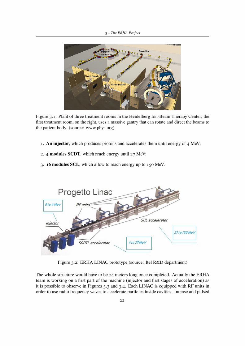
3.1 Plant of three treatment rooms in the Heidelberg Ion-Beam Therapy Center;the first treatment room, on the right, uses a massive gantry that can rotateand direct the beams to the patient body. (source: www.phys.org) . . . . . 22
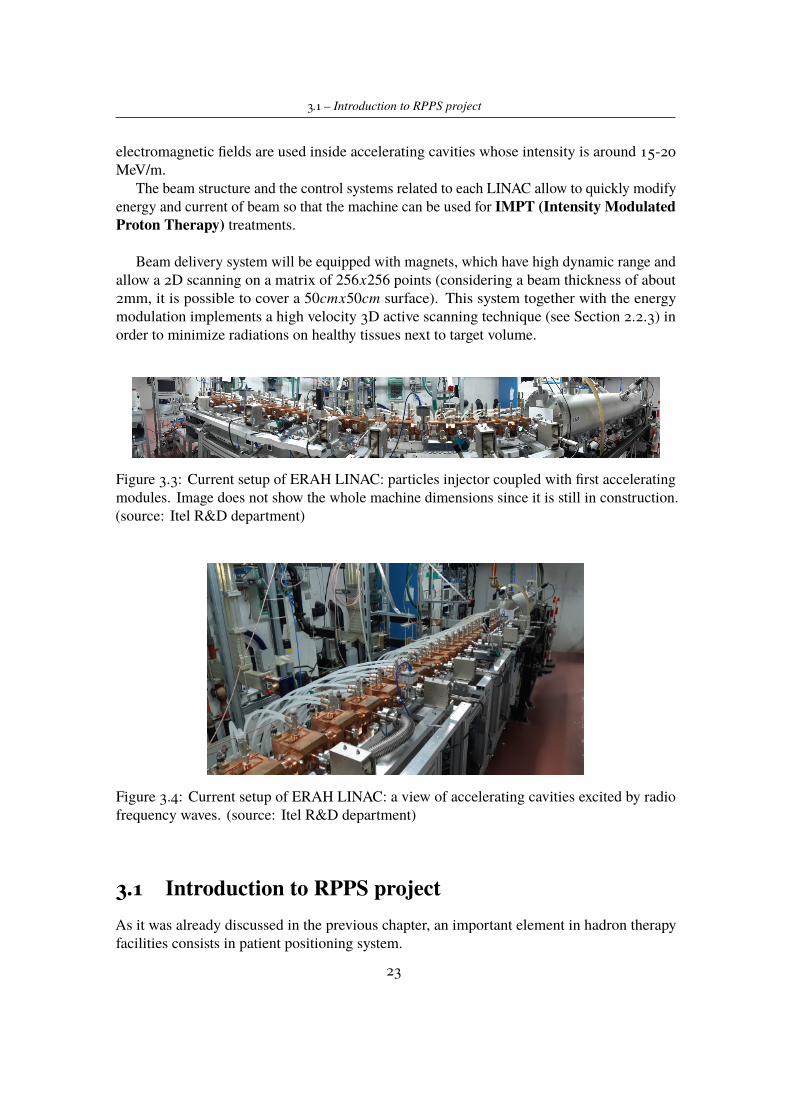
3.2 ERHA LINAC prototype (source: Itel R&D department) . . . . . . . . . . 223.3 Current setup of ERAH LINAC: particles injector coupled with first acceler-
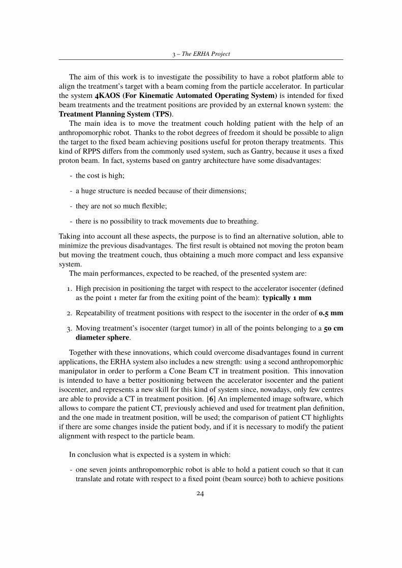
ating modules. Image does not show the whole machine dimensions since itis still in construction. (source: Itel R&D department) . . . . . . . . . . . . 23
3.4 Current setup of ERAH LINAC: a view of accelerating cavities excited byradio frequency waves. (source: Itel R&D department) . . . . . . . . . . . 23
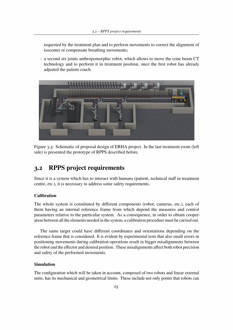
3.5 Schematic of proposal design of ERHA project. In the last treatment room(left side) is presented the prototype of RPPS described before. . . . . . . . 25
4.1 KR210 R3100 ultra C direction of rotation of the axes. [10] . . . . . . . . . 284.2 Additional packages installed on KR C4 controllers. . . . . . . . . . . . . . 294.3 KR 210 R3100 ultra working envelope. [10] . . . . . . . . . . . . . . . . . 304.4 KR 210 R3100 C ultra working envelope. [10] . . . . . . . . . . . . . . . . 314.5 kVueTM One Proton Couch Top designed by Qfix with kVueTM standard
insert (source Qfix company). . . . . . . . . . . . . . . . . . . . . . . . . . 314.6 KR210 R3100 ultra C direction of rotation of the axes. [2] . . . . . . . . . 334.7 Design of robot C-Arm mounting CBCT equipments. . . . . . . . . . . . 334.8 Load position of new configuration proposed for the treatment room in which
RPPS platform is employed. In orange the nozzle from which the particlesbeam enters the room and in red a simulated proton pencil beam. . . . . . . 34
4.9 Load position in simulating environment with highlighted reference framesfor each component. . . . . . . . . . . . . . . . . . . . . . . . . . . . . . 36
4.10 Load position of real suite in the ITEL Mechatronic laboratory. . . . . . . . 364.11 Treatment in point A. Target is ideally located on the couch surface where
theoretically would be the head of patient. . . . . . . . . . . . . . . . . . . 374.12 Treatment in point B. Target is ideally located 10 cm over the couch surface
where theoretically would be the head of patient. . . . . . . . . . . . . . . 384.13 Treatment in point B. Target is ideally located 10 cm over the couch surface
where theoretically would be the head of patient. . . . . . . . . . . . . . . 394.14 Tests for ROBO1 positioning. . . . . . . . . . . . . . . . . . . . . . . . . . 464.15 Tests for ROBO1 and ROBO2 positioning movements. . . . . . . . . . . . 474.16 Safe tool procedure definition for ROBO2. . . . . . . . . . . . . . . . . . 484.17 Workspace representation. . . . . . . . . . . . . . . . . . . . . . . . . . . 484.18 Safe tool procedure definition for ROBO2. . . . . . . . . . . . . . . . . . 494.19 Positioning accuracy measurements through Leica Laser Tracker and light
reflectors on the couch surface. . . . . . . . . . . . . . . . . . . . . . . . . 504.20 LabVIEW control panel to send and get data from ROBO2 controller. . . . 514.21 TPS: load tab . . . . . . . . . . . . . . . . . . . . . . . . . . . . . . . . . 514.22 TPS: DICOM CT tab . . . . . . . . . . . . . . . . . . . . . . . . . . . . . 524.23 TPS: DICOM ION SEQUENCE tab . . . . . . . . . . . . . . . . . . . . . 52A.1 ROBO2 moving program. . . . . . . . . . . . . . . . . . . . . . . . . . . . 57A.2 ROBO1 moving program. . . . . . . . . . . . . . . . . . . . . . . . . . . . 58
vii

B.1 File loaded in robot controller in order to allow Ethernet data exchange withexternal system. . . . . . . . . . . . . . . . . . . . . . . . . . . . . . . . . 59
viii

Chapter 1
Introduction
Many cancers, in particular when at early stage, are curable but, unfortunately, others haveno prognosis at the current state of the art of medicine in this field; so the curability of themneeds to be evaluated in each case. Initially, in its development stage, a tumor is generallywell localized inside the patient body, and it tends to infect to neighbouring lymph nodesand healthy organs. When the tumor is extremely close to vital structure or it is anywayinaccessible, surgery can not be considered as viable option. In these cases radiation therapywill be a useful approach. However, even if aggressive surgery or high dose of radiationand chemotherapy can destroy the cancer, they can cause unacceptable morbidity for thepatient. Therefore must to be found the right balance between tumor cure and risk of possibleinjuries to normal tissues. Most of new studies and researches in radiation therapy are focusedon minimizing the health hazard of the patient, making tumor control probability higher.Moreover radiation therapy is, of course, a less invasive treatment than surgery, and in manycases it represents the healthiest and safest therapy to attend. That is why many companyinvolved in this field are always investigating better solutions to improve technologies availableon the market.
At present, techniques based on beam of high-energy X-rays (often denoted as photonbeam) are the most commonly used in radiotherapy treatments. Other possible forms ofradiation used are: neutrons, electrons beam, radioactive sources, protons, heavier chargedions.
In the last few years, the interest in using ionizing radiations in the treatments of tumor hasgrown. Innovative techniques are investigated in order to increase the treatments efficiency:one of them is proton therapy. The proton therapy is an innovative technique that usesheavy particles positively charged (protons). The advantages, in accordance with physicalphenomena related to this kind of particles, are to be found in the capability of the particlebeam to hit the tumor target with extremely high precision and, at the same time, to reducedangerous effects on the tissues near to the target. These characteristics are particularlyinteresting in treating different kinds of tumor and, in particular, paediatric tumor sincedeveloping tissues are more sensitive to the effects of radiations.
1
1 – Introduction
Nowadays about 50 centres worldwide (between USA, Japan and Europe) and many othersare in construction in the next ten years. Actually in Italy are present 3 operative centres inthis field and the biggest one is in Trento.
This is the context in which Itel Telecomunicazioni srl., a company focused on developingand installing Electromagnetic Shielding for Diagnostic Imaging and located in Ruvo di Puglia(BA), is focused on. Thus, ITEL has started in 2009 a new division, ITELPHARMA, for theproduction of radiopharmaceuticals and services for Nuclear Medicine, and is involved in anongoing project to design a compact Proton Accelerator for Hadron Therapy.
The Itel R&D group is carrying on the ERHA (Enhanced Radioterapy with HAdrons)project. This is an innovative system for proton therapy treatments developed by Itel andcompletely made in Italy. The aim of the project is to design and build a linear protonsaccelerator suitable for clinical purposes, a robotised platform able to place the patient in thetreatment position inside the treatment room, and a software to analyse and develop treatmentplans. At present, the main part of work is focused on the design of the linear accelerator, aninnovative machine which will be able to take the place of much more huge and expansivemachines such as cyclotron and synchrotron.
Thanks to Itel company, I had the possibility to know this reality and spend about fivemonths inside Itel Mechatronic Lab working on the prototype of RPPS (Robotised PatientPositioning System). In particular this thesis work was focused on the goal to investigatethe possibility to use an anthropomorphic manipulator to hold and move the medical couchon which the patient is lying. This kind of system has been thought in order to find a viablealternative to the ones commonly used; as it will be clear in the following, nowadays aregenerally used huge, complex and expansive structures able to guarantee all the specificationsfor a patient positioning system. That is why the innovative idea is to have a compact welldesigned system starting from the particles accelerator, followed by a cheaper and simplerpositioning system. In conclusion, my goal, during this period, was to validate the possibilityto use the anthropomorphic manipulators in order to reach the project objectives throughsimulation and experimental tests.
Chapter 2 summarizes theoretical basics about physics of proton beam; physical phenomenarelated to their interaction with matter and benefits for patient body coming for their utilization.Subsequently, is presented a brief overview of technologies currently used in facilities,equipped for proton therapy, in order to understand and appreciate the context in which ERHAproject would like to introduce innovations.
In Chapter 3 is explained in general terms the ERHA project, presenting what are thegoals the R&D group is intended to achieve. Here is briefly described Itel particle acceleratorcurrently under construction and the progresses already done on it. Then the object of thiswork will be presented: the RPPS system. The attention is focused on the goals on which theproject is based on, making it an innovation in radiation therapy field, and requirements whichshould be attended by the final system.
Chapter 4 presents the work done during the internship in Itel company. In this part,are described, in detail, the design stage of the RPPS, the main results achieved through
2

1 – Introduction
simulations and experimental tests done on the real set up available in the Mechatronic Lab.The last part, Chapter 5, provides conclusions and future developments about the RPPS
project.
3

Chapter 2
Basic on ionizing radiations
Subatomic particles (electrons, protons, neutrons, etc.) and electromagnetic waves withenergy above a few electron volts (eV) are the so called "ionizing radiation". This meansthat, when particles or photons passing through tissues, they lose energy and, at the sametime, ionize them in atomic or nuclear interaction. These kinds of radiations have enoughenergy to damage biological molecules such as DNA. The previous physical phenomenoncan be used to cure cancer concentrating a high dose of radiation at the cancerous cells.In fact dividing cells are more susceptible to radiation than non-dividing cells and thesewill kill dividing cancerous cells more effectively than healthy cells. The key of a goodand healthy treatment is a controlled amount of radiations directed at the concentrationsof cancerous cells in order to cause damages to them rather than to normal cells of patient body.
In the last few years, the interest in using particles therapy for cancer treatments has grown.The reason of this interest has to be found in the pattern of energy disposition in matter, whichheavy charged particle beams have, that represents the main advantage in using protons orheavy ions rather than more conventional photons (X-ray) or electrons.
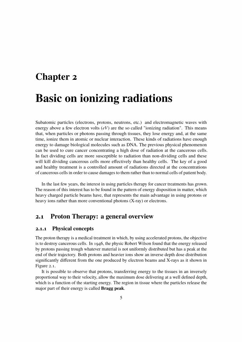
2.1 Proton Therapy: a general overview2.1.1 Physical conceptsThe proton therapy is a medical treatment in which, by using accelerated protons, the objectiveis to destroy cancerous cells. In 1946, the physic Robert Wilson found that the energy releasedby protons passing trough whatever material is not uniformly distributed but has a peak at theend of their trajectory. Both protons and heavier ions show an inverse depth dose distributionsignificantly different from the one produced by electron beams and X-rays as it shown inFigure 2.1.
It is possible to observe that protons, transferring energy to the tissues in an inverselyproportional way to their velocity, allow the maximum dose delivering at a well defined depth,which is a function of the starting energy. The region in tissue where the particles release themajor part of their energy is called Bragg peak.
5
2 – Basic on ionizing radiations
Figure 2.1: Comparison between dose released in tissues by electrons, photons and protons.
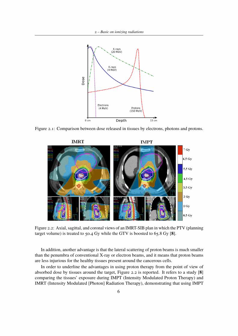
Figure 2.2: Axial, sagittal, and coronal views of an IMRT-SIB plan in which the PTV (planningtarget volume) is treated to 50.4 Gy while the GTV is boosted to 65.8 Gy [8].
In addition, another advantage is that the lateral scattering of proton beams is much smallerthan the penumbra of conventional X-ray or electron beams, and it means that proton beamsare less injurious for the healthy tissues present around the cancerous cells.
In order to underline the advantages in using proton therapy from the point of view ofabsorbed dose by tissues around the target, Figure 2.2 is reported. It refers to a study [8]comparing the tissues’ exposure during IMPT (Intensity Modulated Proton Therapy) andIMRT (Intensity Modulated [Photon] Radiation Therapy), demonstrating that using IMPT
6
2.1 – Proton Therapy: a general overview
allows increased doses to the GTV (gross tumor volume) with decreased toxicity to criticalstructures.
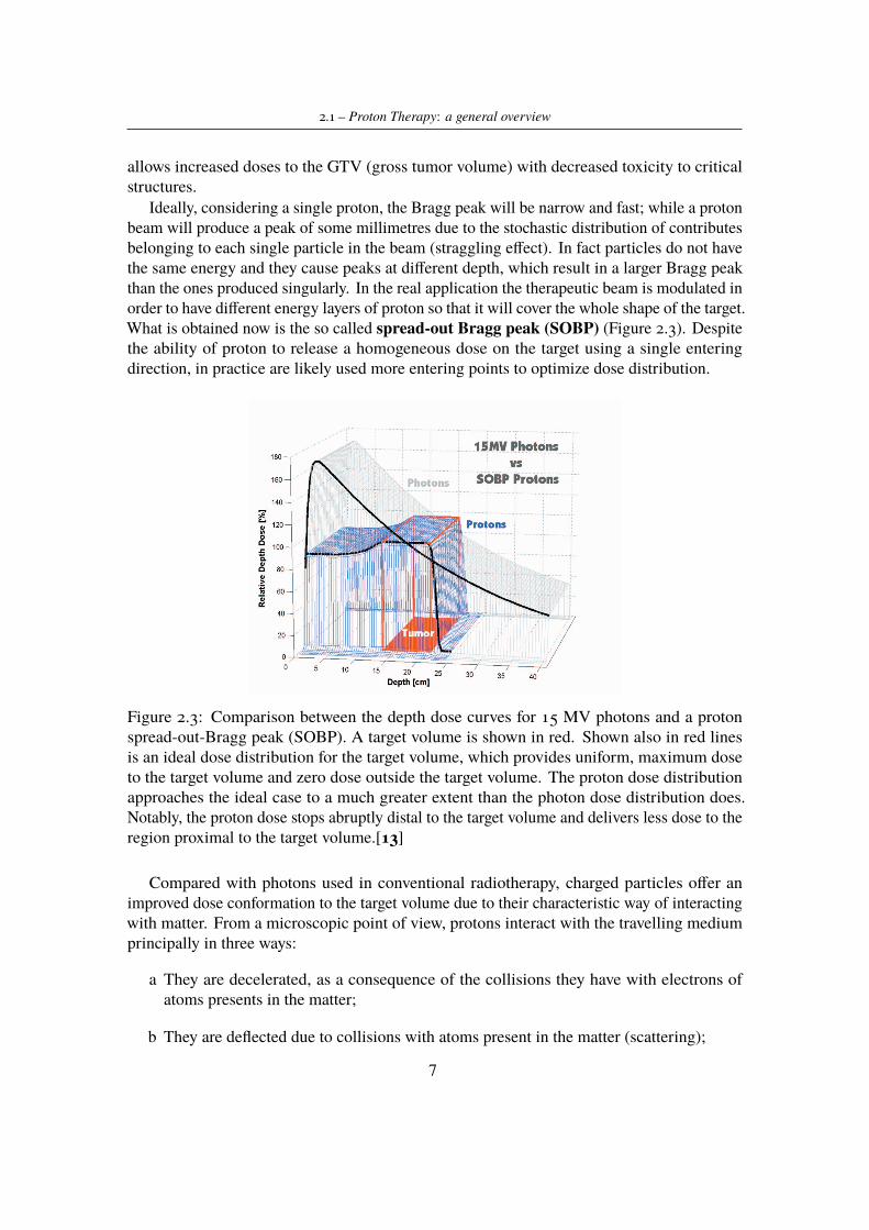
Ideally, considering a single proton, the Bragg peak will be narrow and fast; while a protonbeam will produce a peak of some millimetres due to the stochastic distribution of contributesbelonging to each single particle in the beam (straggling effect). In fact particles do not havethe same energy and they cause peaks at different depth, which result in a larger Bragg peakthan the ones produced singularly. In the real application the therapeutic beam is modulated inorder to have different energy layers of proton so that it will cover the whole shape of the target.What is obtained now is the so called spread-out Bragg peak (SOBP) (Figure 2.3). Despitethe ability of proton to release a homogeneous dose on the target using a single enteringdirection, in practice are likely used more entering points to optimize dose distribution.
Figure 2.3: Comparison between the depth dose curves for 15 MV photons and a protonspread-out-Bragg peak (SOBP). A target volume is shown in red. Shown also in red linesis an ideal dose distribution for the target volume, which provides uniform, maximum doseto the target volume and zero dose outside the target volume. The proton dose distributionapproaches the ideal case to a much greater extent than the photon dose distribution does.Notably, the proton dose stops abruptly distal to the target volume and delivers less dose to theregion proximal to the target volume.[13]
Compared with photons used in conventional radiotherapy, charged particles offer animproved dose conformation to the target volume due to their characteristic way of interactingwith matter. From a microscopic point of view, protons interact with the travelling mediumprincipally in three ways:
a They are decelerated, as a consequence of the collisions they have with electrons ofatoms presents in the matter;
b They are deflected due to collisions with atoms present in the matter (scattering);
7
2 – Basic on ionizing radiations
c Thanks to collisions with nuclei of atoms in the matter, secondary particles are generated.
Particle Stopping Power theory
Heavy charged particles traversing matter lose energy primarily through the ionization andexcitation of atoms. They exert electromagnetic forces (due to opposite charge) on atomicelectrons and impart energy sufficient to ionize the atoms or to excite them. This kind ofparticles travels an almost straight path through matter, losing energy continuously in smallamounts through collisions with atomic electrons. Note that before stopping and completelyloosing their energy, a proton suffers thousands of collisions for centimetres of travellingmaterial.
For a particle of energy E travelling a distance x with speed v, the energy rate loss inmedium for ionizations expressed in MeV
cm is mathematically described by the followingBethe-Bloch expression:
−dEdx=
4πNA
mec2z2
β2ZAρ ln
2mec2β2γ2
I− relativistic terms) (2.1)
where:
- c is the speed of light
- β is the ratio between the velocity of particle and the speed of light ( vc )
- NA is the Avogadro number
- z is the particle charge
- me is the rest mass of the electron
- Z, A, ρ, I are the atomic number, the mass number, the density and the mean excitationenergy of the medium, respectively.
The following equation describes the inverse proportionality between x and energy E. Onetherefore defines the mass stopping power which is positive as:
S = −dEdX
[MeVg/cm2 ] (2.2)
The dominant part in the Bethe-Bloch formula is 1v2 and the Z dependence. The 1
v2 ≈ 1E
dependence yields an increase in energy loss with decreasing particle energy. At low energieselectrons are collected from the target and Z in the nominator decreases rapidly yielding adistinct maximum of energy loss at low energies. When the energy loss is plotted over thepenetration depth, its maximum is located at the end of the track causing the Bragg peak.
Energy loss occurs in discrete interactions and thus has statistical fluctuations. Protonspassing through a solid or simply air will lose slightly different amounts of energy. As aconsequence, monoenergetic protons will not all stop at exactly the same depth in somematerial. This effect, called range straggling, means that Bragg peak will have someminimum width even if the incident beam has zero energy spread.
8
2.1 – Proton Therapy: a general overview
Scattering
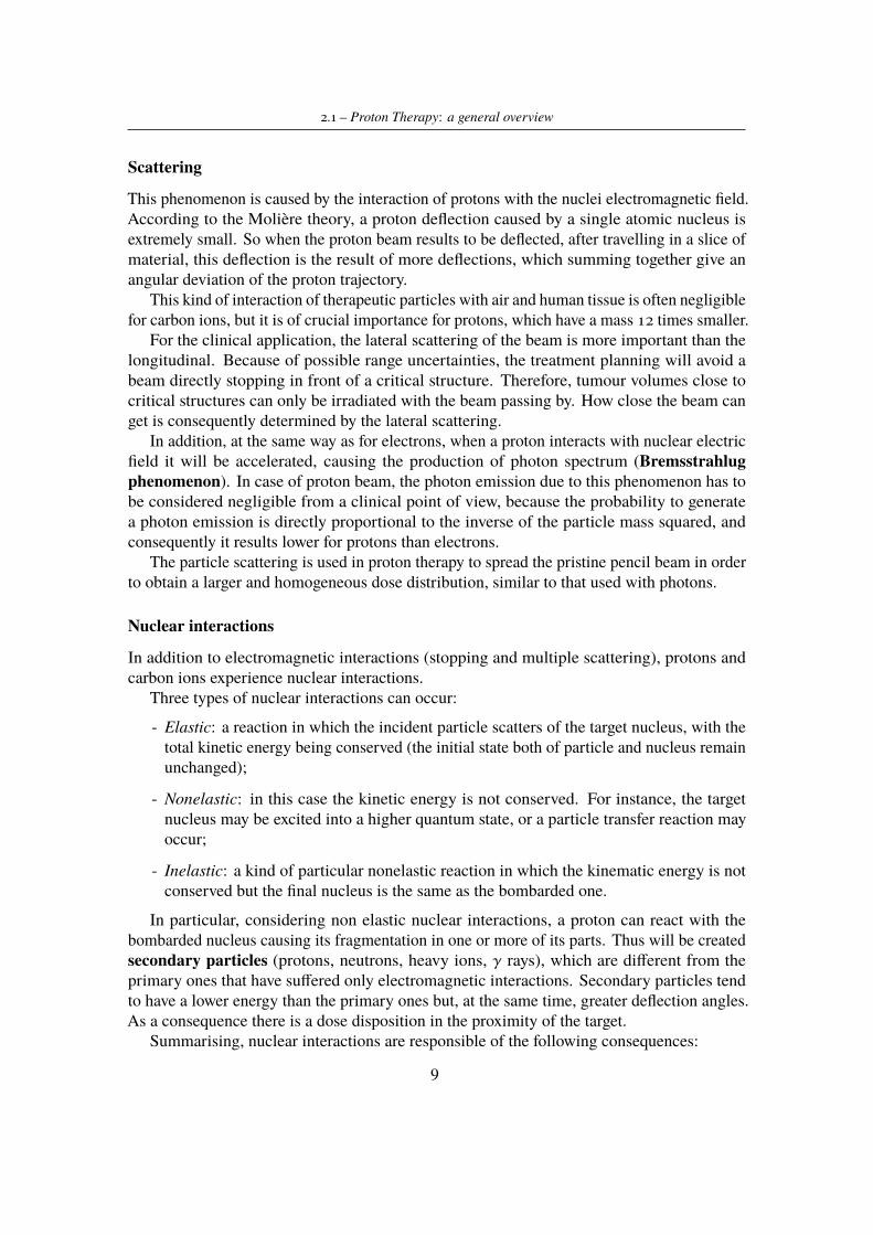
This phenomenon is caused by the interaction of protons with the nuclei electromagnetic field.According to the Molière theory, a proton deflection caused by a single atomic nucleus isextremely small. So when the proton beam results to be deflected, after travelling in a slice ofmaterial, this deflection is the result of more deflections, which summing together give anangular deviation of the proton trajectory.
This kind of interaction of therapeutic particles with air and human tissue is often negligiblefor carbon ions, but it is of crucial importance for protons, which have a mass 12 times smaller.
For the clinical application, the lateral scattering of the beam is more important than thelongitudinal. Because of possible range uncertainties, the treatment planning will avoid abeam directly stopping in front of a critical structure. Therefore, tumour volumes close tocritical structures can only be irradiated with the beam passing by. How close the beam canget is consequently determined by the lateral scattering.
In addition, at the same way as for electrons, when a proton interacts with nuclear electricfield it will be accelerated, causing the production of photon spectrum (Bremsstrahlugphenomenon). In case of proton beam, the photon emission due to this phenomenon has tobe considered negligible from a clinical point of view, because the probability to generatea photon emission is directly proportional to the inverse of the particle mass squared, andconsequently it results lower for protons than electrons.
The particle scattering is used in proton therapy to spread the pristine pencil beam in orderto obtain a larger and homogeneous dose distribution, similar to that used with photons.
Nuclear interactions
In addition to electromagnetic interactions (stopping and multiple scattering), protons andcarbon ions experience nuclear interactions.
Three types of nuclear interactions can occur:
- Elastic: a reaction in which the incident particle scatters of the target nucleus, with thetotal kinetic energy being conserved (the initial state both of particle and nucleus remainunchanged);
- Nonelastic: in this case the kinetic energy is not conserved. For instance, the targetnucleus may be excited into a higher quantum state, or a particle transfer reaction mayoccur;
- Inelastic: a kind of particular nonelastic reaction in which the kinematic energy is notconserved but the final nucleus is the same as the bombarded one.
In particular, considering non elastic nuclear interactions, a proton can react with thebombarded nucleus causing its fragmentation in one or more of its parts. Thus will be createdsecondary particles (protons, neutrons, heavy ions, γ rays), which are different from theprimary ones that have suffered only electromagnetic interactions. Secondary particles tendto have a lower energy than the primary ones but, at the same time, greater deflection angles.As a consequence there is a dose disposition in the proximity of the target.
Summarising, nuclear interactions are responsible of the following consequences:
9
2 – Basic on ionizing radiations
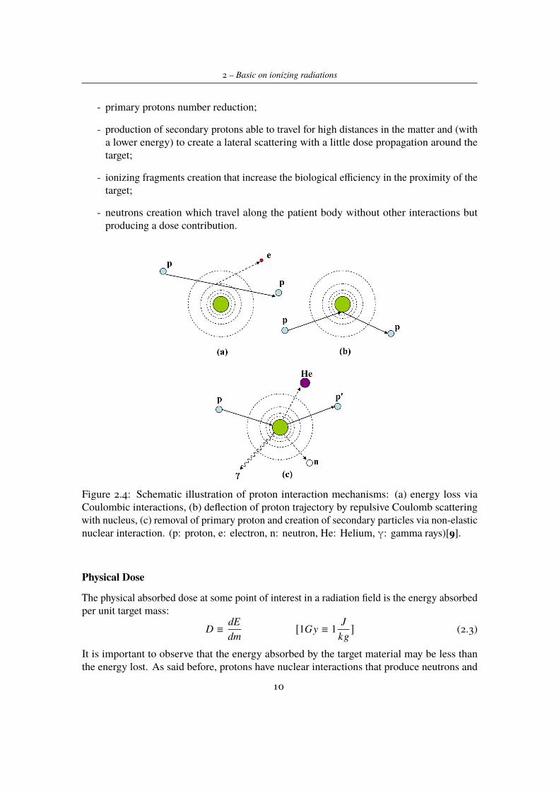
- primary protons number reduction;
- production of secondary protons able to travel for high distances in the matter and (witha lower energy) to create a lateral scattering with a little dose propagation around thetarget;
- ionizing fragments creation that increase the biological efficiency in the proximity of thetarget;
- neutrons creation which travel along the patient body without other interactions butproducing a dose contribution.
Figure 2.4: Schematic illustration of proton interaction mechanisms: (a) energy loss viaCoulombic interactions, (b) deflection of proton trajectory by repulsive Coulomb scatteringwith nucleus, (c) removal of primary proton and creation of secondary particles via non-elasticnuclear interaction. (p: proton, e: electron, n: neutron, He: Helium, γ: gamma rays)[9].
Physical Dose
The physical absorbed dose at some point of interest in a radiation field is the energy absorbedper unit target mass:
D ≡dEdm
[1Gy ≡ 1J
kg] (2.3)
It is important to observe that the energy absorbed by the target material may be less thanthe energy lost. As said before, protons have nuclear interactions that produce neutrons and
10
2.1 – Proton Therapy: a general overview
others secondary particles. Neutrons (being neutral), instead of depositing their energy in thematerial, go away and usually stop in the shield walls of the radiation therapy facility. Thisresults in a lost energy about a few percent.
The following equation relates the physical absorbed dose to the fluence and stoppingpower:
D ≡ ΦS (2.4)where Φ stands for the number of particles passing trough a sphere in the time unit and S isthe mass stopping power already defined.
Typical value for stopping power is 5MeV/(g/cm2) and a therapeutic physical dose perfraction is in the order of 1Gy; on the basis of these values, fluence results to be of the orderof 109 protons per cm2.
Charged particles offer several additional advantages compared with photons, not only fortheir interaction with matter but also for radiobiological properties.
Biological effects are related to the absorbed dose, defined before; however the absorbeddose alone is not sufficient to estimate the biological effects. Physical dose is accepted asstandard because it is relatively easy to define and measure.
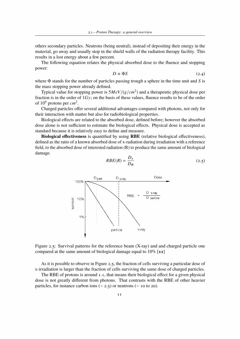
Biological effectiveness is quantified by using RBE (relative biological effectiveness),defined as the ratio of a known absorbed dose of x-radiation during irradiation with a referencefield, to the absorbed dose of interested radiation (R) to produce the same amount of biologicaldamage.
RBE(R) =Dx
DR(2.5)
Figure 2.5: Survival patterns for the reference beam (X-ray) and and charged particle onecompared at the same amount of biological damage equal to 10% [11]
As it is possible to observe in Figure 2.5, the fraction of cells surviving a particular dose ofx-irradiation is larger than the fraction of cells surviving the same dose of charged particles.
The RBE of protons is around 1.1, that means their biological effect for a given physicaldose is not greatly different from photons. That contrasts with the RBE of other heavierparticles, for instance carbon ions (∼ 2.5) or neutrons (∼ 10 to 20).
11
2 – Basic on ionizing radiations
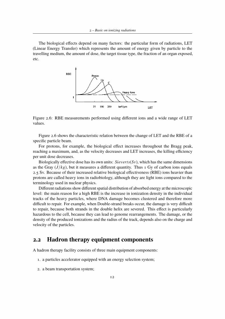
The biological effects depend on many factors: the particular form of radiations, LET(Linear Energy Transfer) which represents the amount of energy given by particle to thetravelling medium, the amount of dose, the target tissue type, the fraction of an organ exposed,etc.
Figure 2.6: RBE measurements performed using different ions and a wide range of LETvalues.
Figure 2.6 shows the characteristic relation between the change of LET and the RBE of aspecific particle beam.
For protons, for example, the biological effect increases throughout the Bragg peak,reaching a maximum, and, as the velocity decreases and LET increases, the killing efficiencyper unit dose decreases.
Biologically effective dose has its own units: Sieverts(Sv), which has the same dimensionsas the Gray (J/kg), but it measures a different quantity. Thus 1 Gy of carbon ions equals2.5 Sv. Because of their increased relative biological effectiveness (RBE) ions heavier thanprotons are called heavy ions in radiobiology, although they are light ions compared to theterminology used in nuclear physics.
Different radiations show different spatial distribution of absorbed energy at the microscopiclevel: the main reason for a high RBE is the increase in ionization density in the individualtracks of the heavy particles, where DNA damage becomes clustered and therefore moredifficult to repair. For example, when Double-strand breaks occur, the damage is very difficultto repair, because both strands in the double helix are severed. This effect is particularlyhazardous to the cell, because they can lead to genome rearrangements. The damage, or thedensity of the produced ionizations and the radius of the track, depends also on the charge andvelocity of the particles.
2.2 Hadron therapy equipment componentsA hadron therapy facility consists of three main equipment components:
1. a particles accelerator equipped with an energy selection system;
2. a beam transportation system;
12
2.2 – Hadron therapy equipment components
3. a beam delivery system, which may include gantry, beam nozzle, volume-tracking andbeam-gating device, positioning and immobilization system.
2.2.1 Particles acceleratorThe first step in generating a beam, suitable in hadron therapy, is to have a source of protonsor other ions, which can be then accelerated to energies sufficient for treatment. For example,this can be done starting from hydrogen atoms and separating their electrons from protons byusing an electric field. Once proton have been generated, they must be accelerated in order toreach the distal edge of a tumor.
Particle accelerators use an electrical field to accelerate photons and a magnetic field tosteer the charged particles. The physical process of acceleration is described with the Lorentzforce laws: F = qE and F = qvxB. They show that an electric field E increases the energy ofa particle with charge q while a magnetic field B defines their trajectory. In order to acceleratecharged particles in a compact machine, it is efficient to reuse the electric one. This is theworking principle in circular machines, such as cyclotron or synchrotron, in which the sameelectric field is used to repeatedly steer the particle beam.
In photon therapy linear accelerators are commonly used. For what concerns hadrontherapy using a linear accelerator (LINAC) is more complicated, because it does not producesufficient electric field to build a compact system. Nowadays the most common and diffusedare circular and cyclic accelerators like cyclotrons, isochronous cyclotrons, synchrocyclotronsand synchrotrons. The first and the latter are the most widespread in hadron therapy.
Accelerators requirements
The overall goal of an accelerator for therapy with protons and heavier ions is to producea beam that penetrates 26-38 cm in human tissue. Translated in particle energy, incidentprotons of 215 MeV are required on the patient surface and the beam emerging from theaccelerator must have an energy between 200-250 MeV (depending on the efficiency of thedelivery system in use). For carbon ions the beam energy at the accelerator exit must bebetween 300-400 MeV/u.
In addition the beam must have sufficient intensity to allow therapeutic doses to be deliveredwithin few minutes. Typically beam intensities of between 1.8 x 10¹¹ and 3.6 x 10¹¹ particlesper minute are required if doses of 2 Gy min−1 are delivered uniformly to target volumes ofone litre. Beam intensities too high are not easy to control, and to achieve reasonable doserates and treat patient safely, the intensity range should be between 10-20 nA.
Cyclotron
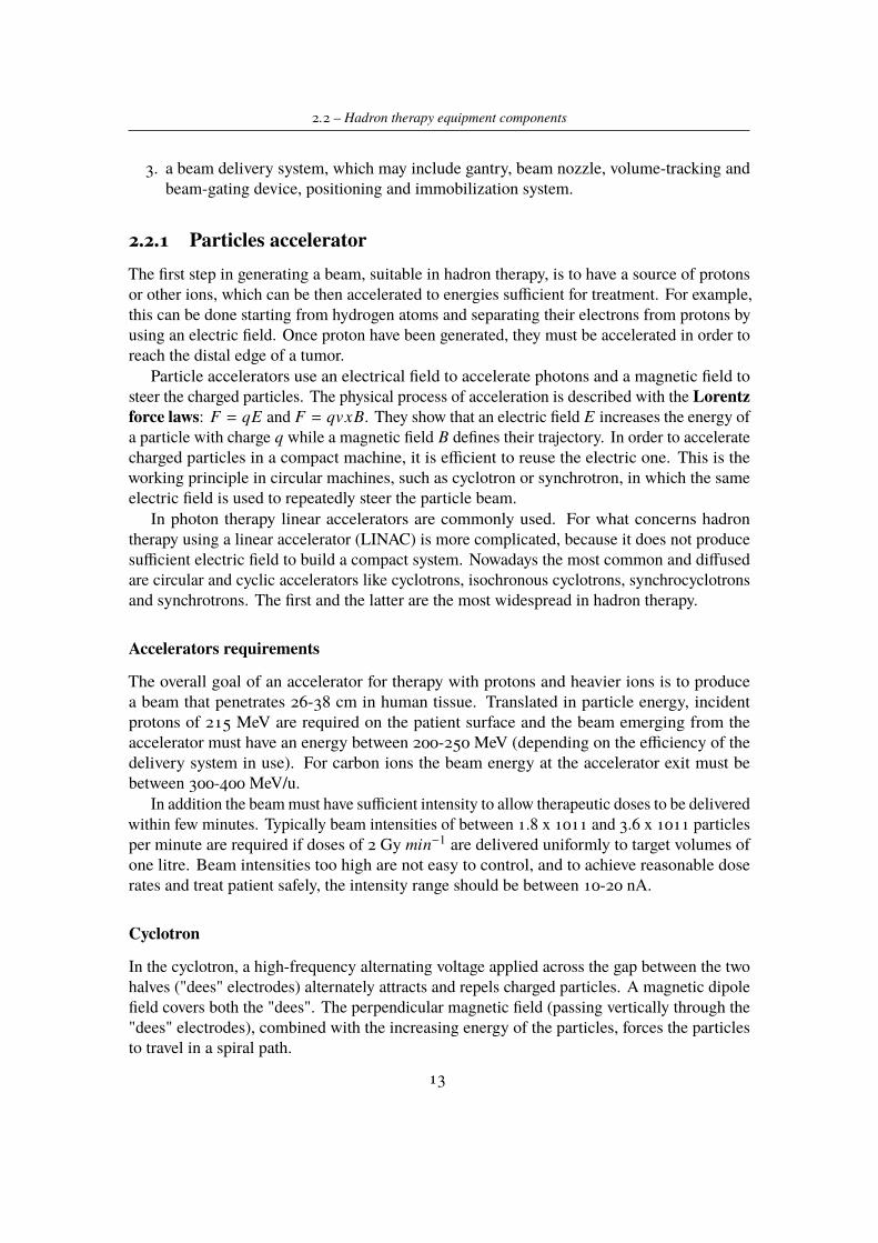
In the cyclotron, a high-frequency alternating voltage applied across the gap between the twohalves ("dees" electrodes) alternately attracts and repels charged particles. A magnetic dipolefield covers both the "dees". The perpendicular magnetic field (passing vertically through the"dees" electrodes), combined with the increasing energy of the particles, forces the particlesto travel in a spiral path.
13
2 – Basic on ionizing radiations
With no change in energy the charged particles in a magnetic field will follow a circularpath. In the cyclotron, energy is applied to the particles as they cross the gap between theelectrodes. The polarity of the electric field is switched at the exact time when the beamreaches the gap to ensure acceleration of the beam and not deceleration.
Cyclotrons for hadron therapy have relatively few adjustable parameters, and producecontinuous wave beams.
The continuous time structure, the intensity stability, the relative simplicity together withthe limited dimensions compared with synchrotron are the main advantages of cyclotron. Onthe other hand the fixed energy together with particle type availability are the main drawbacks.
Figure 2.7: Schematic diagram of a cyclotron.[15]
Synchrotron
While a cyclotron uses a constant magnetic field and a constant frequency applied electric field,both of these fields are varied in the synchrotron and one is varied in the synchrocyclotron.By increasing these parameters appropriately as the particles gain energy, their path can beheld constant as they are accelerated.
The beam is injected from outside the synchrotron by, typically, a LINAC with an energy of3 to 7 MeV. To achieve acceleration, the magnetic field and the frequency of the acceleratingelectric field must be increased in synchrony. Because of the finite time required to cycle themagnets, synchrotron produces a pulsed output.
When the beam reaches the desired energy it is extracted and directed to the treatmentroom through the beam transport system.
14
2.2 – Hadron therapy equipment components
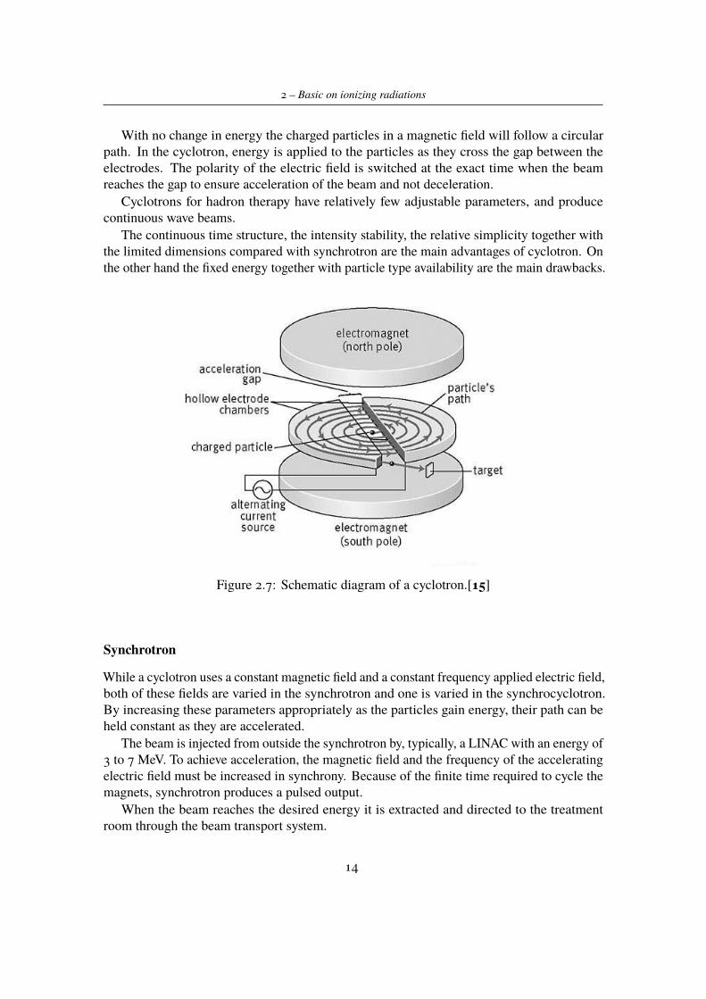
Using a synchrotron allows to obtain a range of energies, since the beam extractionoperations do not depend of the machine characteristics but on the switching on of a magnet.
Figure 2.8: Schematic of synchrotron used in Loma Linda (California - USA) centre. [12]
Linear accelerator
A linear accelerator is able to produce particles beam travelling on a linear path and acceleratedby electromagnetic field, which can be static or variable. Typically it is done using differentresonant cavities in sequence powered by radio frequency sources.
Linear accelerators can be of different types, depending on the technologies used foraccelerating particles. The technology employed in Itel project involves two kinds of linearaccelerator:
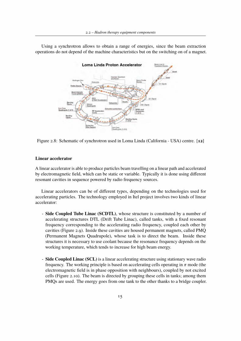
- Side Coupled Tube Linac (SCDTL), whose structure is constituted by a number ofaccelerating structures DTL (Drift Tube Linac), called tanks, with a fixed resonantfrequency corresponding to the accelerating radio frequency, coupled each other bycavities (Figure 2.9). Inside these cavities are housed permanent magnets, called PMQ(Permanent Magnets Quadrupole), whose task is to direct the beam. Inside thesestructures it is necessary to use coolant because the resonance frequency depends on theworking temperature, which tends to increase for high beam energy.
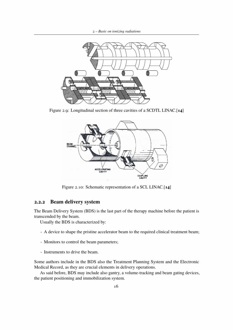
- Side Coupled Linac (SCL) is a linear accelerating structure using stationary wave radiofrequency. The working principle is based on accelerating cells operating in π mode (theelectromagnetic field is in phase opposition with neighbours), coupled by not excitedcells (Figure 2.10). The beam is directed by grouping these cells in tanks; among themPMQs are used. The energy goes from one tank to the other thanks to a bridge coupler.
15
2 – Basic on ionizing radiations
Figure 2.9: Longitudinal section of three cavities of a SCDTL LINAC.[14]
Figure 2.10: Schematic representation of a SCL LINAC.[14]
2.2.2 Beam delivery systemThe Beam Delivery System (BDS) is the last part of the therapy machine before the patient istranscended by the beam.
Usually the BDS is characterized by:
- A device to shape the pristine accelerator beam to the required clinical treatment beam;
- Monitors to control the beam parameters;
- Instruments to drive the beam.
Some authors include in the BDS also the Treatment Planning System and the ElectronicMedical Record, as they are crucial elements in delivery operations.
As said before, BDS may include also gantry, a volume-tracking and beam gating devices,the patient positioning and immobilization system.
16
2.2 – Hadron therapy equipment components
2.2.3 Beam delivery techniquesA beam of particles coming from the accelerator is well described by a 2D Gaussian functioncalculated as a function of the particle type, energy and of the kind and depth of the materialcrossed from the vacuum exit window.
The starting transversal and longitudinal dimensions are as small as possible to reducethe cost of the beam transport; the typical FWHM (Full Wave Half Maximum) is lessthan 10 mm and is smaller than typical tumor volume (between 1 cm and 20 cm alongx, y and z). The beam coming from the accelerator has a fixed energy and direction andhence, without corrections, it cannot cover any kind of volume. Tumors can have veryirregular shapes and can be located from few millimetres to 30 centimetres in depth fromthe patient skin and close to critical organs, and this is different from one patient to another one.
Therefore it is needed to modulate the beam in order to irradiate uniformly the wholetumor volume. This volume is composed by particular thickness and surface, which arelocated in parallel and orthogonal planes with respect to the beam direction, respectively.Then the particle beam has to be modulated in energy depending on tumor thickness, and alsomodulated transversally depending on its shape.
Energy modulation
Modulation in energy can be done through the use of passive or active systems. The first onesare used when the beam has a fixed energy; in this case the beam energy is modulated byusing an absorber device composed by multiple carbon block. These elements slow particlesuntil they reach the desired energy. Modifying thickness of carbon blocks it is possible toregulate energy. This kind of modulation has drawbacks:
- The greater the energy variation is the more will be the beam energy spread. In order toavoid a polychromatic beam, two magnetic dipoles curve the beam in order to allow onlyparticles with right energy to follow the imposed trajectory.
- Beam also worsens in traversal direction, because of the lateral scattering phenomenon(already meet in section 1.1 of this chapter).
Modulating beam energy by using active devices allows to avoid the above drawbacks. Inthis case the energy is modulated directly inside the accelerator varying the power supply ofgenerators. Just before the patient the beam is spread out to cover the overall target volume.The methods used to spread out the beam can be passive or dynamic.
Dose distribution in transversal direction
As said before, it is necessary to enlarge the beam in order to hit the whole tumor volume.Also in this case are available two different methods: passive or active.
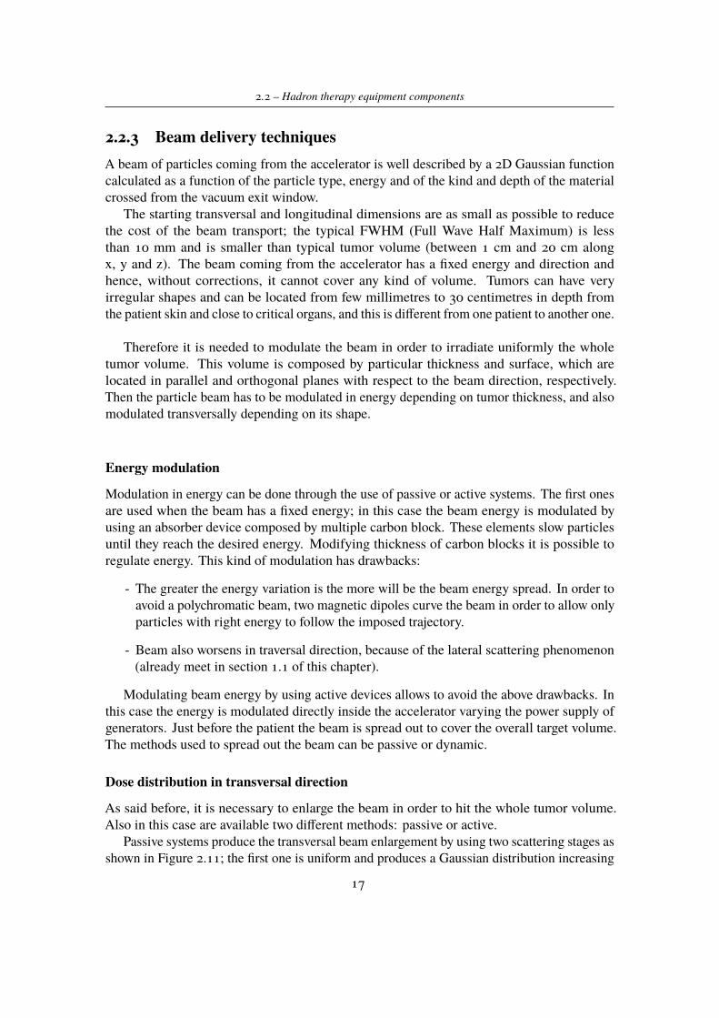
Passive systems produce the transversal beam enlargement by using two scattering stages asshown in Figure 2.11; the first one is uniform and produces a Gaussian distribution increasing
17
2 – Basic on ionizing radiations
the beam width and modulating the energy, while this distribution is homogenized by a secondscatter. In order to occlude the mid and the outer part of Gaussian distribution, collimator areused to stop unwanted radiations. Since tumor volumes have not regular shapes, it is neededto use a personalized compensator to get a further dose distribution modulation. Also in thiscase there are drawbacks, as previously discussed.
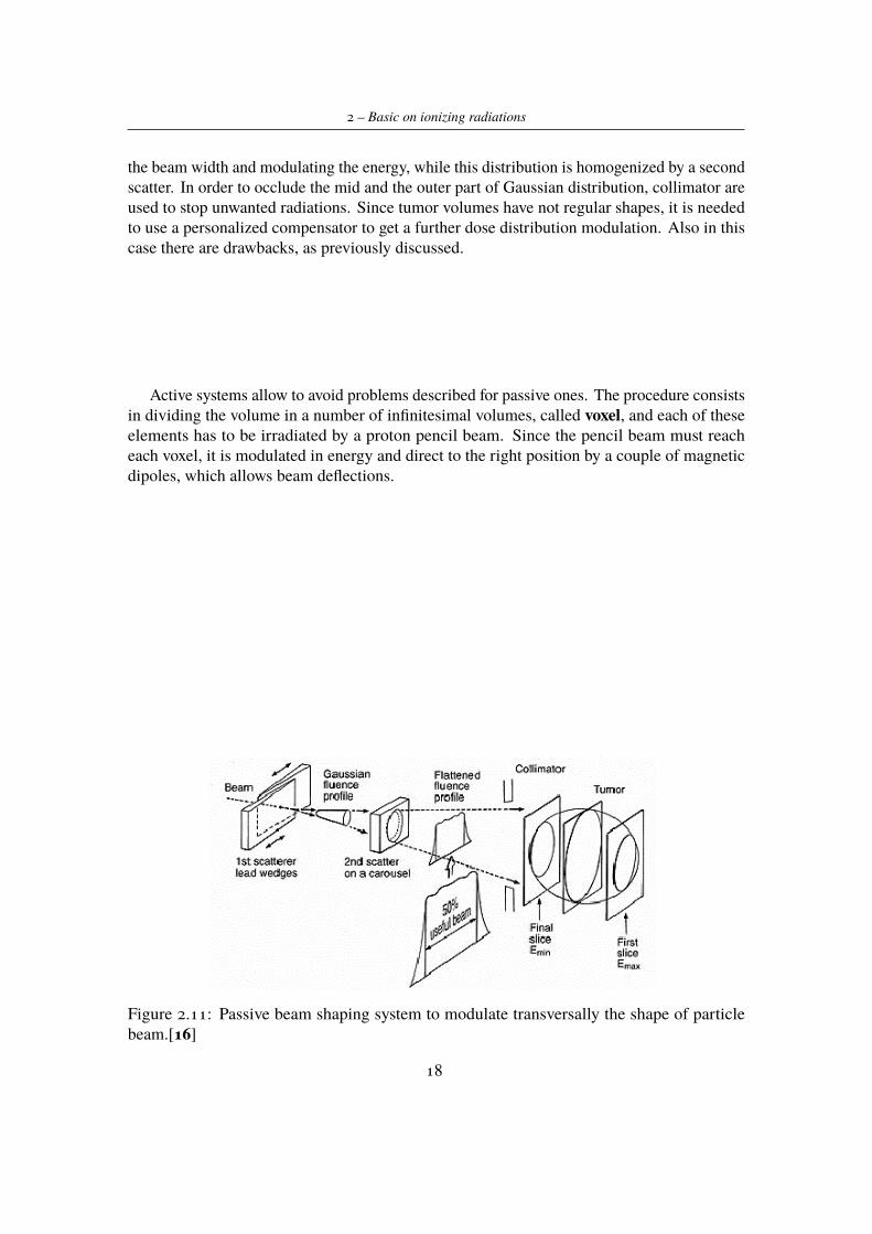
Active systems allow to avoid problems described for passive ones. The procedure consistsin dividing the volume in a number of infinitesimal volumes, called voxel, and each of theseelements has to be irradiated by a proton pencil beam. Since the pencil beam must reacheach voxel, it is modulated in energy and direct to the right position by a couple of magneticdipoles, which allows beam deflections.
Figure 2.11: Passive beam shaping system to modulate transversally the shape of particlebeam.[16]
18
2.2 – Hadron therapy equipment components
Figure 2.12: Diagram of a typical pencil beam scanning system. Two sets of scanning magnetsscan the beam in a 2D pattern: the beam range is adjusted by changing the beam energyentering the nozzle. In the usual case, all spots for the deepest range are scanned, the energyis changed, and all spots with the new range are scanned, etc., until the entire target volumehas been scanned.[17]
Breathing movements
Another element which has to be taken in account in beam delivery procedure is the following:the target may be close to moving organs as a consequence of patient breathing movements.In this way also the target is not fixed and it should cause a wrong dose delivery.
Three are the possible techniques to overcome this problem:
. Respiratory Gating: beam delivery is synchronized with breathing movements in orderto reduce as much as possible the possible errors in dose distribution;
. Tumor is irradiated using different directions for beam entering the body; in this way themovements cause a less overdose of radiations;
. Movements are detected by a device which in real time describes the 3D position oftarget. These informations are used by delivery system to modulate the energy anddirection of particle beam.
19

Chapter 3
The ERHA Project
The present thesis work is part of the ERHA Project (Enhanced Radiotherapy withHAdrons), which is an innovative project patent by ITEL Telecomunicazioni s.r.l. in the fieldof proton therapy.
The main idea is to find a new system available for proton therapy treatments, havingadvantages with respect to the actual systems by using:
- Proton linear accelerator (LINAC);
- Robotised platform for patient positioning;
- A software to analyze and develop treatment plans.Nowadays all available options for particles acceleration are investigated and used. The
acceleration system, whichever it is, integrated with beam transporting lines and treatmentrooms form a typical proton therapy centre. Usually a Ion Beam Therapy centre is equippedwith a gantry structure, used in order to modify the direction of the beam entering in thepatient body (Figure 3.1). What is easily observable is that, apart from the space neededfor particle accelerator, also the gantry structure, which is huge and complex in terms ofcomponents needed to direct beams, takes up a big space. This is one of the main issues toinvestigate in other beam delivery techniques, in order to save space and reduce the risk thatsomething goes wrong (mostly inside electrical components used in beam deflection).
Therefore in ERHA project the purpose is to use a modular and compact linear acceleratorrather than the most common machines, such as circular accelerators, and a robotised patientpositioning system, which works with fixed beam direction inside treatment rooms.
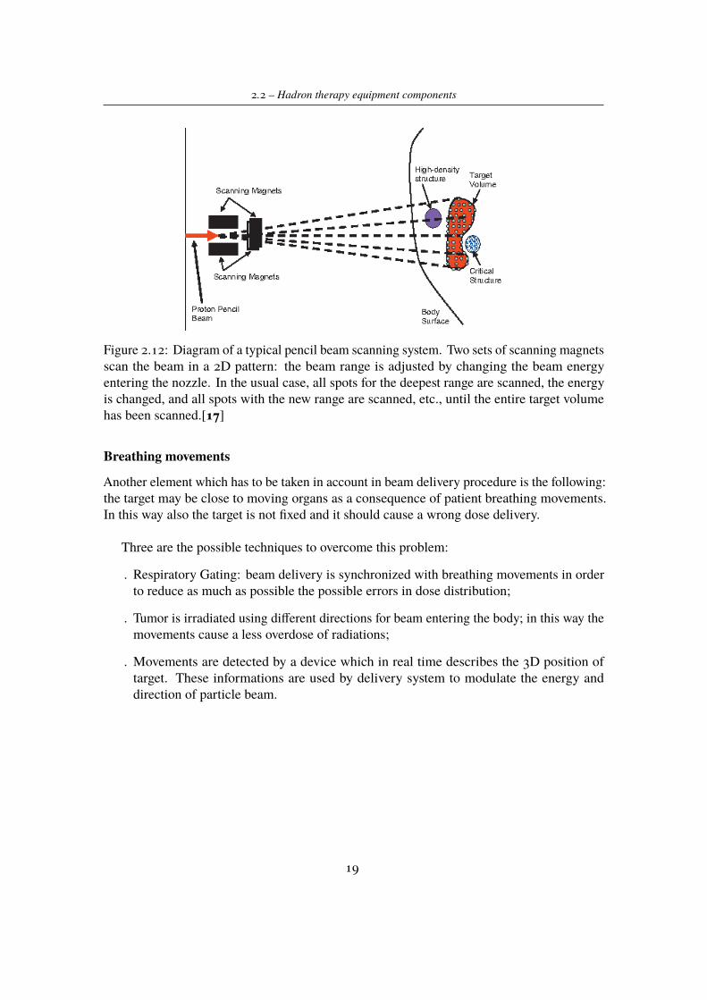
As said before, actually in ITEL Telecomunicazioni s.r.l. the R&D group is working indeveloping the LINAC (Linear Accelerator) in order to reach the beam intensity requestedby proton beam treatments. ERHA accelerator guarantees better performances in terms ofbeam optical quality and quantity of radiation emitted in the room. Particles, coming fromthe injector, are accelerated across the line thanks to low and high energy cavities until theyreach the energy useful for treatment (Figure 3.2). The structure shall consist of differentaccelerating stages (see section 2.2.1):
21
3 – The ERHA Project
Figure 3.1: Plant of three treatment rooms in the Heidelberg Ion-Beam Therapy Center; thefirst treatment room, on the right, uses a massive gantry that can rotate and direct the beams tothe patient body. (source: www.phys.org)
1. An injector, which produces protons and accelerates them until energy of 4 MeV;
2. 4 modules SCDT, which reach energy until 27 MeV;
3. 16 modules SCL, which allow to reach energy up to 150 MeV.
Figure 3.2: ERHA LINAC prototype (source: Itel R&D department)
The whole structure would have to be 24 meters long once completed. Actually the ERHAteam is working on a first part of the machine (injector and first stages of acceleration) asit is possible to observe in Figures 3.3 and 3.4. Each LINAC is equipped with RF units inorder to use radio frequency waves to accelerate particles inside cavities. Intense and pulsed
22
3.1 – Introduction to RPPS project
electromagnetic fields are used inside accelerating cavities whose intensity is around 15-20MeV/m.
The beam structure and the control systems related to each LINAC allow to quickly modifyenergy and current of beam so that the machine can be used for IMPT (Intensity ModulatedProton Therapy) treatments.
Beam delivery system will be equipped with magnets, which have high dynamic range andallow a 2D scanning on a matrix of 256x256 points (considering a beam thickness of about2mm, it is possible to cover a 50cmx50cm surface). This system together with the energymodulation implements a high velocity 3D active scanning technique (see Section 2.2.3) inorder to minimize radiations on healthy tissues next to target volume.
Figure 3.3: Current setup of ERAH LINAC: particles injector coupled with first acceleratingmodules. Image does not show the whole machine dimensions since it is still in construction.(source: Itel R&D department)
Figure 3.4: Current setup of ERAH LINAC: a view of accelerating cavities excited by radiofrequency waves. (source: Itel R&D department)
3.1 Introduction to RPPS projectAs it was already discussed in the previous chapter, an important element in hadron therapyfacilities consists in patient positioning system.
23
3 – The ERHA Project
The aim of this work is to investigate the possibility to have a robot platform able toalign the treatment’s target with a beam coming from the particle accelerator. In particularthe system 4KAOS (For Kinematic Automated Operating System) is intended for fixedbeam treatments and the treatment positions are provided by an external known system: theTreatment Planning System (TPS).
The main idea is to move the treatment couch holding patient with the help of ananthropomorphic robot. Thanks to the robot degrees of freedom it should be possible to alignthe target to the fixed beam achieving positions useful for proton therapy treatments. Thiskind of RPPS differs from the commonly used system, such as Gantry, because it uses a fixedproton beam. In fact, systems based on gantry architecture have some disadvantages:
- the cost is high;
- a huge structure is needed because of their dimensions;
- they are not so much flexible;
- there is no possibility to track movements due to breathing.
Taking into account all these aspects, the purpose is to find an alternative solution, able tominimize the previous disadvantages. The first result is obtained not moving the proton beambut moving the treatment couch, thus obtaining a much more compact and less expansivesystem.
The main performances, expected to be reached, of the presented system are:
1. High precision in positioning the target with respect to the accelerator isocenter (definedas the point 1 meter far from the exiting point of the beam): typically 1 mm
2. Repeatability of treatment positions with respect to the isocenter in the order of 0.5 mm
3. Moving treatment’s isocenter (target tumor) in all of the points belonging to a 50 cmdiameter sphere.
Together with these innovations, which could overcome disadvantages found in currentapplications, the ERHA system also includes a new strength: using a second anthropomorphicmanipulator in order to perform a Cone Beam CT in treatment position. This innovationis intended to have a better positioning between the accelerator isocenter and the patientisocenter, and represents a new skill for this kind of system since, nowadays, only few centresare able to provide a CT in treatment position. [6] An implemented image software, whichallows to compare the patient CT, previously achieved and used for treatment plan definition,and the one made in treatment position, will be used; the comparison of patient CT highlightsif there are some changes inside the patient body, and if it is necessary to modify the patientalignment with respect to the particle beam.
In conclusion what is expected is a system in which:
- one seven joints anthropomorphic robot is able to hold a patient couch so that it cantranslate and rotate with respect to a fixed point (beam source) both to achieve positions
24
3.2 – RPPS project requirements
requested by the treatment plan and to perform movements to correct the alignment ofisocenter or compensate breathing movements;
- a second six joints anthropomorphic robot, which allows to move the cone beam CTtechnology and to perform it in treatment position, once the first robot has alreadyadjusted the patient couch.
Figure 3.5: Schematic of proposal design of ERHA project. In the last treatment room (leftside) is presented the prototype of RPPS described before.
3.2 RPPS project requirementsSince it is a system which has to interact with humans (patient, technical staff in treatmentcentre, etc.), it is necessary to address some safety requirements.
Calibration
The whole system is constituted by different components (robot, cameras, etc.), each ofthem having an internal reference frame from which depend the measures and controlparameters relative to the particular system. As a consequence, in order to obtain cooper-ation between all the elements needed in the system, a calibration procedure must be carried out.
The same target could have different coordinates and orientations depending on thereference frame that is considered. It is evident by experimental tests that also small errors inpositioning movements during calibration operations result in bigger misalignments betweenthe robot end the effector and desired position. These misalignments affect both robot precisionand safety of the performed movements.
Simulation
The configuration which will be taken in account, composed of two robots and linear externalunits, has its mechanical and geometrical limits. These include not only points that robots can
25
3 – The ERHA Project
not reach due to hardware limits of their joints, but also elements in the room with which therobot can collide.
In order to prevent unwanted behaviour (such as singularities which result in not predictablerobot movements) it was thought to add a simulation software in which, by solving the inverserobot kinematics, the robot trajectory can be reconstructed. From simulations can be predictthe robot behaviour, the points it will reach and, eventually, strange movements, such as theones due to singularities situations that can compromise the safety of whole system.
Naturally simulation software must be able to communicate in real time with the robotsand other components in order to provide to the operator all the needed elements for safetyoperations.
Motion
Once the trajectory has been calculated through simulation in order to reach the desiredpoint without risks for patient or operators or the system itself, the system must elaborate thetrajectory and send active command to robots. It is necessary to take into account all thehardware and software limits for each robot, the presence of a linear external unit, the fact thatthe two robots need to communicate each other to synchronize their motion.
Strictly related to robot motion, is the safety motion requirement. Since the system workswith humans, must be taken into account their motion, so that robot movements should notbe dangerous for persons present in the room; in this way specific areas are configured asworking space or violated one and robot velocity is intentionally kept low.
Vision
In order to ensure high precision in all positioning operations, the positions of the machinesand the position of patient on the couch should be measured by an external system. In thisway, using a feedback signal coming from this external system, a wrong position could becorrected.
For this reason two different kinds of system are implemented:
1. A Laser Tracker is used to control the couch position inside the treatment room. Usingsome reflectors positioned on the couch it is possible to measure the position of thecouch (and consequentially of robots) in the available space
2. 3D stereo cameras system able to monitor the patient body and relate it to the couchin order to take into account all the possible misalignments and movements due tobreathing.
This part of ERHA system will not be analysed in this thesis since it is part of collaborationbetween ITEL and Politecnico di Bari, which is studying the stereo cameras system.
26
Chapter 4
RPPS development
On the basis of the purposes and objectives discussed in the previous sections, the followingwork investigates the project reliability. As will be clarified subsequently, the analysis is basedon the results coming from simulation tests and also tests on the real set-up developed inlaboratory.
4.1 Specifications analysisBefore starting with the description of the different tests, a brief overview regarding projectspecifications will be now presented; it contains all the technical information about differentcomponents that will take part in the whole set-up. Note that, since the project is just in itsinitial stage, some components are not physically available but are just designed and simulatedby prototypes.
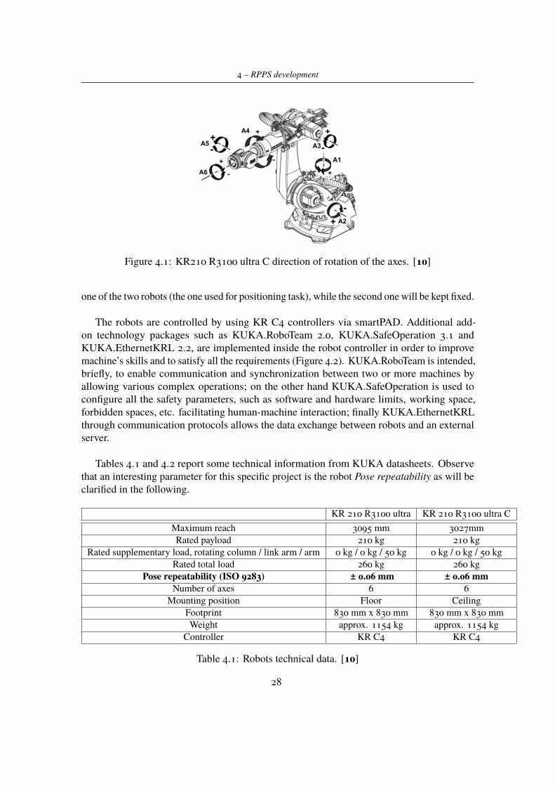
4.1.1 KUKA RobotsITEL already has a patented robot patient positioning system which should be improved tomeet the current needs of proton therapy treatments. In the Mechatronic lab, are currentlyavailable two six-joints anthropomorphic KUKA robots (Figure 4.1) able to perform the tasksrequested by the project and, at the same time, suitable to be used with particle beams utilizedin hadron therapy from the point of view of constructing materials.
In particular, robots belong to the following series:
- KR 210 R3100 C ultra
- KR 210 R3100 ultra.
Both of them are equipped with an additional external linear axis. The only differenceis that the first one utilizes a ceiling slide, so it is overturned with respect to the secondone. The external additional axis allows to have a greater workspace available for robotmovements. As it will be explained better, the linear external unit will be utilized only for
27
4 – RPPS development
Figure 4.1: KR210 R3100 ultra C direction of rotation of the axes. [10]
one of the two robots (the one used for positioning task), while the second one will be kept fixed.
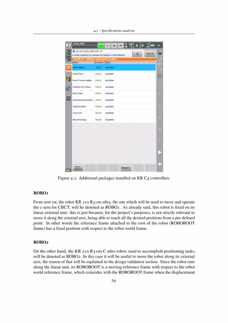
The robots are controlled by using KR C4 controllers via smartPAD. Additional add-on technology packages such as KUKA.RoboTeam 2.0, KUKA.SafeOperation 3.1 andKUKA.EthernetKRL 2.2, are implemented inside the robot controller in order to improvemachine’s skills and to satisfy all the requirements (Figure 4.2). KUKA.RoboTeam is intended,briefly, to enable communication and synchronization between two or more machines byallowing various complex operations; on the other hand KUKA.SafeOperation is used toconfigure all the safety parameters, such as software and hardware limits, working space,forbidden spaces, etc. facilitating human-machine interaction; finally KUKA.EthernetKRLthrough communication protocols allows the data exchange between robots and an externalserver.
Tables 4.1 and 4.2 report some technical information from KUKA datasheets. Observethat an interesting parameter for this specific project is the robot Pose repeatability as will beclarified in the following.
KR 210 R3100 ultra KR 210 R3100 ultra CMaximum reach 3095 mm 3027mmRated payload 210 kg 210 kg
Rated supplementary load, rotating column / link arm / arm 0 kg / 0 kg / 50 kg 0 kg / 0 kg / 50 kgRated total load 260 kg 260 kg
Pose repeatability (ISO 9283) ± 0.06 mm ± 0.06 mmNumber of axes 6 6
Mounting position Floor CeilingFootprint 830 mm x 830 mm 830 mm x 830 mmWeight approx. 1154 kg approx. 1154 kg
Controller KR C4 KR C4
Table 4.1: Robots technical data. [10]
28
4.1 – Specifications analysis
Figure 4.2: Additional packages installed on KR C4 controllers.
ROBO1
From now on, the robot KR 210 R3100 ultra, the one which will be used to move and operatethe c-arm for CBCT, will be denoted as ROBO1. As already said, this robot is fixed on itslinear external unit: this is just because, for the project’s purposes, is not strictly relevant tomove it along the external axis, being able to reach all the desired positions from a pre-definedpoint. In other words the reference frame attached to the root of the robot (ROBOROOTframe) has a fixed position with respect to the robot world frame.
ROBO2
On the other hand, the KR 210 R3100 C ultra robot, used to accomplish positioning tasks,will be denoted as ROBO2. In this case it will be useful to move the robot along its externalaxis; the reason of that will be explained in the design validation section. Since the robot runsalong the linear unit, its ROBOROOT is a moving reference frame with respect to the robotworld reference frame, which coincides with the ROBOROOT frame when the displacement
29
4 – RPPS development
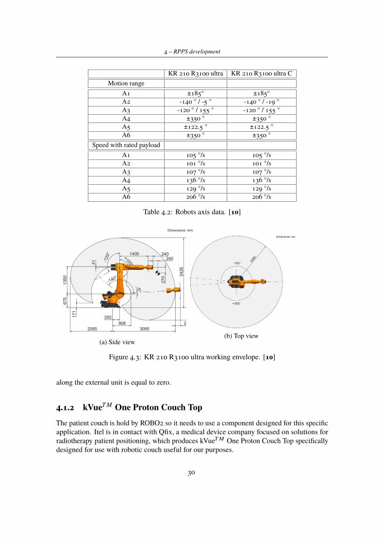
KR 210 R3100 ultra KR 210 R3100 ultra CMotion range
A1 ±185° ±185°A2 -140 ° / -5 ° -140 ° / -19 °A3 -120 ° / 155 ° -120 ° / 155 °A4 ±350 ° ±350 °A5 ±122.5 ° ±122.5 °A6 ±350 ° ±350 °
Speed with rated payloadA1 105 °/s 105 °/sA2 101 °/s 101 °/sA3 107 °/s 107 °/sA4 136 °/s 136 °/sA5 129 °/s 129 °/sA6 206 °/s 206 °/s
Table 4.2: Robots axis data. [10]
(a) Side view(b) Top view
Figure 4.3: KR 210 R3100 ultra working envelope. [10]
along the external unit is equal to zero.
4.1.2 kVueT M One Proton Couch TopThe patient couch is hold by ROBO2 so it needs to use a component designed for this specificapplication. Itel is in contact with Qfix, a medical device company focused on solutions forradiotherapy patient positioning, which produces kVueTM One Proton Couch Top specificallydesigned for use with robotic couch useful for our purposes.
30
4.1 – Specifications analysis
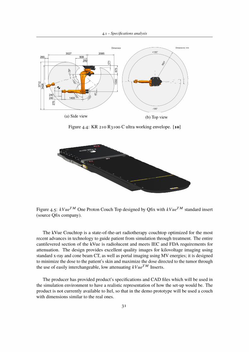
(a) Side view (b) Top view
Figure 4.4: KR 210 R3100 C ultra working envelope. [10]
Figure 4.5: kVueTM One Proton Couch Top designed by Qfix with kVueTM standard insert(source Qfix company).
The kVue Couchtop is a state-of-the-art radiotherapy couchtop optimized for the mostrecent advances in technology to guide patient from simulation through treatment. The entirecantilevered section of the kVue is radiolucent and meets IEC and FDA requirements forattenuation. The design provides excellent quality images for kilovoltage imaging usingstandard x-ray and cone beam CT, as well as portal imaging using MV energies; it is designedto minimize the dose to the patient’s skin and maximize the dose directed to the tumor throughthe use of easily interchangeable, low attenuating kVueTM Inserts.
The producer has provided product’s specifications and CAD files which will be used inthe simulation environment to have a realistic representation of how the set-up would be. Theproduct is not currently available to Itel, so that in the demo prototype will be used a couchwith dimensions similar to the real ones.
31
4 – RPPS development
4.1.3 CBCT C-arcA crucial point for the designed system is the possibility to use volumetric image guidance,thanks to a Cone Beam CT system in order to improve precision and efficiency of beamdelivery system. In CBCT technology, imaging is accomplished by rotating x-ray source anddetector around a fixed fulcrum, which is usually the centre of region of interest. Duringrotations, sequential planar projection images of the field of view (FOV) are acquired and thenoverlapped in order to obtain a 3D representation.[4] Usually the acquisition process requiresa complete rotation of the machine but, according to recent studies [2], a rotation of 180◦ plusthe beam angle it would be sufficient for reconstruction of a full FOV. As a partner in ERHAproject, a research group of Politecnico di Bari is developing the algorithm for 3D imagereconstruction, which shall include also the case of non complete x-ray source rotation during2D images acquisition.
Analysing the state of the art of CBCT systems [6] and according to purposes and require-ments of the project, a robotic C-Arm plus a concentric rotating C-ring was designed (Figure4.7). Initially it was considered a single C-Arm mounting CBCT technology, which shouldrotate thanks to the robot movements. In order to simplify the movements in the room andavoid possible limitations due to mechanical limits, the new idea is to use the robot movementsonly to place the C-Arm in imaging position and then perform the rotation rotating only theC-ring mounting x-ray source and image detector.
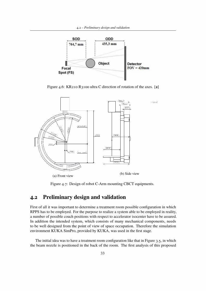
Considering projection images (on patient body) of 260x260mm2 that would be enough inorder to detect all of the possible kinds of tumor, the FOV on panel detector results fixed to420x420mm2. To be sure that this data are consistent with products present on the market, hasbeen contacted a Imaging Components producer field, which proposed a panel detector forCBCT suitable whit previous requirements. Knowing FOV dimension and fixing the Sourceto Imager Distance (SID) to 1200mm (enough to allow C-Arm positioning over couch), bymathematical computations are defined (Figure 4.6):
- Focal Spot ≈ 20◦
- Source to Object Distance (SOD) = 764,7mm
- Object to Detector Distance (ODD) = 435,3mm.
Itel R&D group is still in contact with the imaging components producer regarding an x-raysource consistent with our design requirements.
Unfortunately during this work it was not possible to produce the component, since it wasdesigned for our specific application and it is not a commercial product. In order to performvalidation tests, has been realized a prototype of C-Arm (without rotating C-ring), which hasSID and panel detector dimensions equal to the ones previous described. Rotating movementswill be tested and, moving robot joints, analysed in order to demonstrate the reliability of thereal set-up.
32
4.2 – Preliminary design and validation
Figure 4.6: KR210 R3100 ultra C direction of rotation of the axes. [2]
(a) Front view (b) Side view
Figure 4.7: Design of robot C-Arm mounting CBCT equipments.
4.2 Preliminary design and validationFirst of all it was important to determine a treatment room possible configuration in whichRPPS has to be employed. For the purpose to realize a system able to be employed in reality,a number of possible couch positions with respect to accelerator isocenter have to be assured.In addition the intended system, which consists of many mechanical components, needsto be well designed from the point of view of space occupation. Therefore the simulationenvironment KUKA SimPro, provided by KUKA, was used in the first stage.
The initial idea was to have a treatment room configuration like that in Figure 3.5, in whichthe beam nozzle is positioned in the back of the room. The first analysis of this proposed
33
4 – RPPS development
configuration showed that it was not valid in terms of space occupancy. For this analysis andfor the following ones, the system capability to reach at least three specific treatment positionshas been evaluated:
- LOCATION A: the couch orientation is parallel to the exiting direction of the particlebeam (aligned with the base reference system x axis);
- LOCATION B: the couch is orthogonal to the exiting beam rotating in positive directionaround the base z axis (rotation of +90◦ starting from Position A);
- LOCATION C: the couch is orthogonal to the exiting beam rotating in negative directionaround the base z axis (rotation of −90◦ starting from Position A);
For all the three situations is set a tratment distance of 65 cm (distance of the target fromproton beam exiting point); this value has been determined by ERHA team on the basis ofaccelerator characteristics. Of course points A, B and C are just a first requirement requestedto the positioning platform, which must guarantee much more treatment points. Note thatthese locations have been selected on the basis of the fact that in proton therapy are commonlytreated brain tumours, head and neck cancers, pelvis and abdomen sites.
As result of first simulation, the configuration initially proposed showed some problemmainly in robot positioning tasks; the available space was not enough to make possible robotcooperation and synchronous movements.
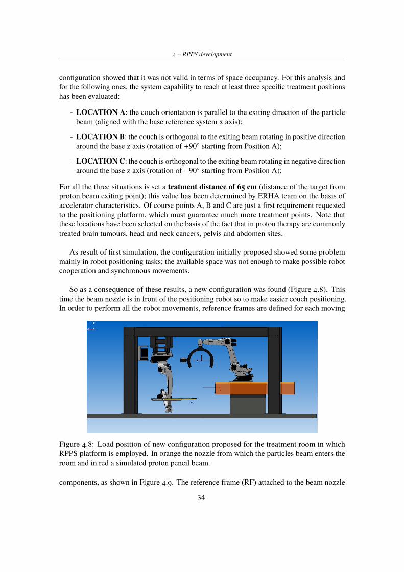
So as a consequence of these results, a new configuration was found (Figure 4.8). Thistime the beam nozzle is in front of the positioning robot so to make easier couch positioning.In order to perform all the robot movements, reference frames are defined for each moving
Figure 4.8: Load position of new configuration proposed for the treatment room in whichRPPS platform is employed. In orange the nozzle from which the particles beam enters theroom and in red a simulated proton pencil beam.
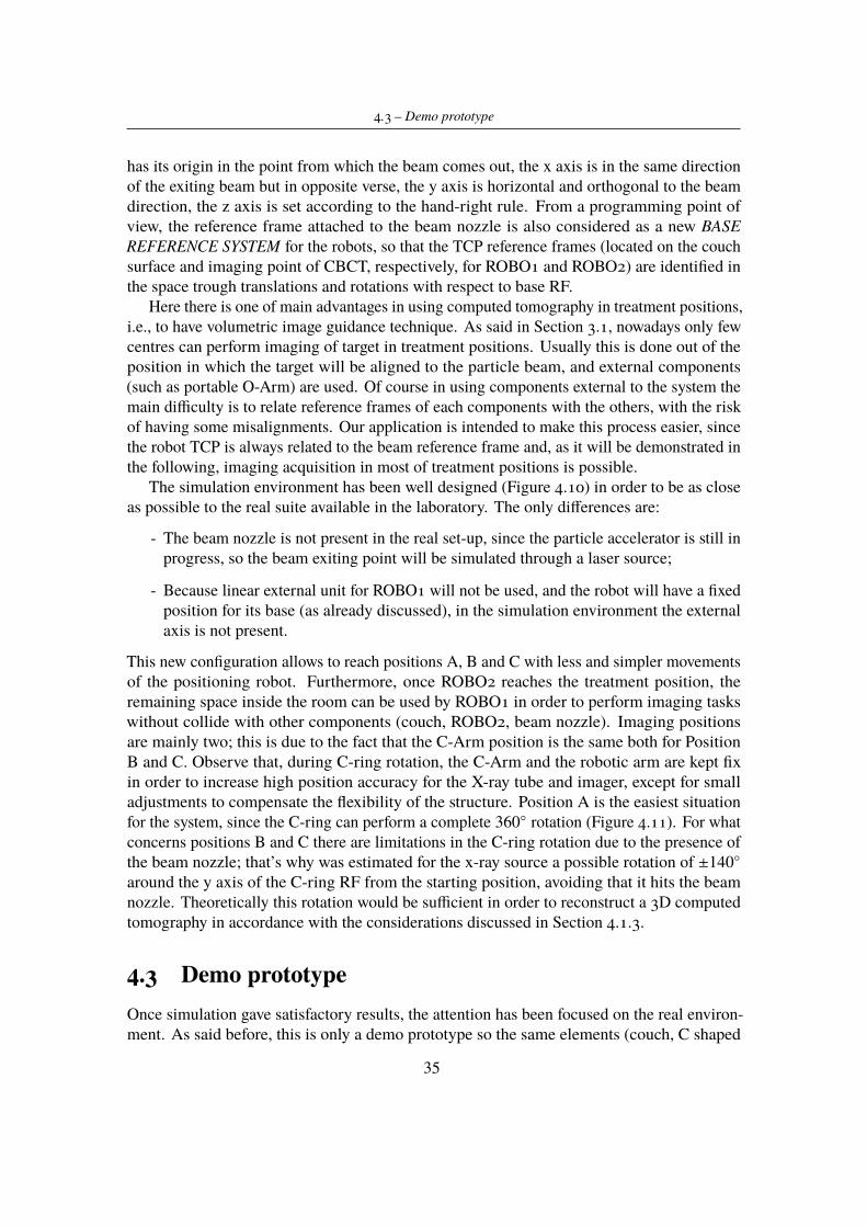
components, as shown in Figure 4.9. The reference frame (RF) attached to the beam nozzle
34
4.3 – Demo prototype
has its origin in the point from which the beam comes out, the x axis is in the same directionof the exiting beam but in opposite verse, the y axis is horizontal and orthogonal to the beamdirection, the z axis is set according to the hand-right rule. From a programming point ofview, the reference frame attached to the beam nozzle is also considered as a new BASEREFERENCE SYSTEM for the robots, so that the TCP reference frames (located on the couchsurface and imaging point of CBCT, respectively, for ROBO1 and ROBO2) are identified inthe space trough translations and rotations with respect to base RF.
Here there is one of main advantages in using computed tomography in treatment positions,i.e., to have volumetric image guidance technique. As said in Section 3.1, nowadays only fewcentres can perform imaging of target in treatment positions. Usually this is done out of theposition in which the target will be aligned to the particle beam, and external components(such as portable O-Arm) are used. Of course in using components external to the system themain difficulty is to relate reference frames of each components with the others, with the riskof having some misalignments. Our application is intended to make this process easier, sincethe robot TCP is always related to the beam reference frame and, as it will be demonstrated inthe following, imaging acquisition in most of treatment positions is possible.
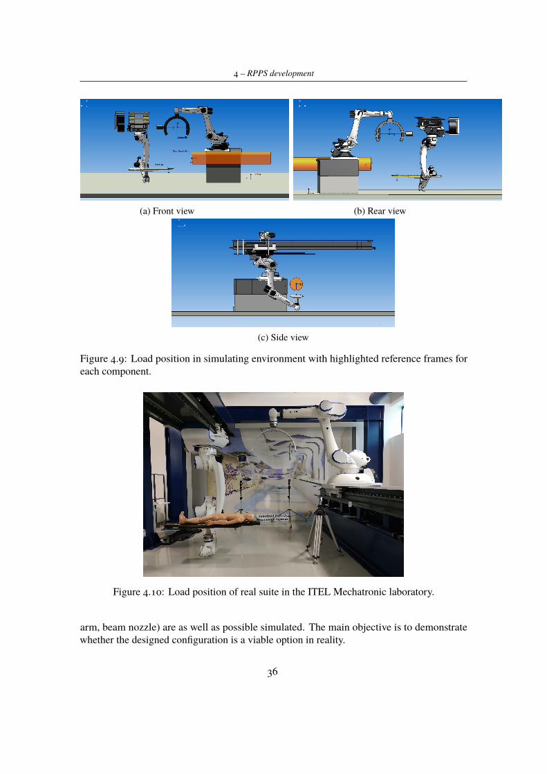
The simulation environment has been well designed (Figure 4.10) in order to be as closeas possible to the real suite available in the laboratory. The only differences are:
- The beam nozzle is not present in the real set-up, since the particle accelerator is still inprogress, so the beam exiting point will be simulated through a laser source;
- Because linear external unit for ROBO1 will not be used, and the robot will have a fixedposition for its base (as already discussed), in the simulation environment the externalaxis is not present.
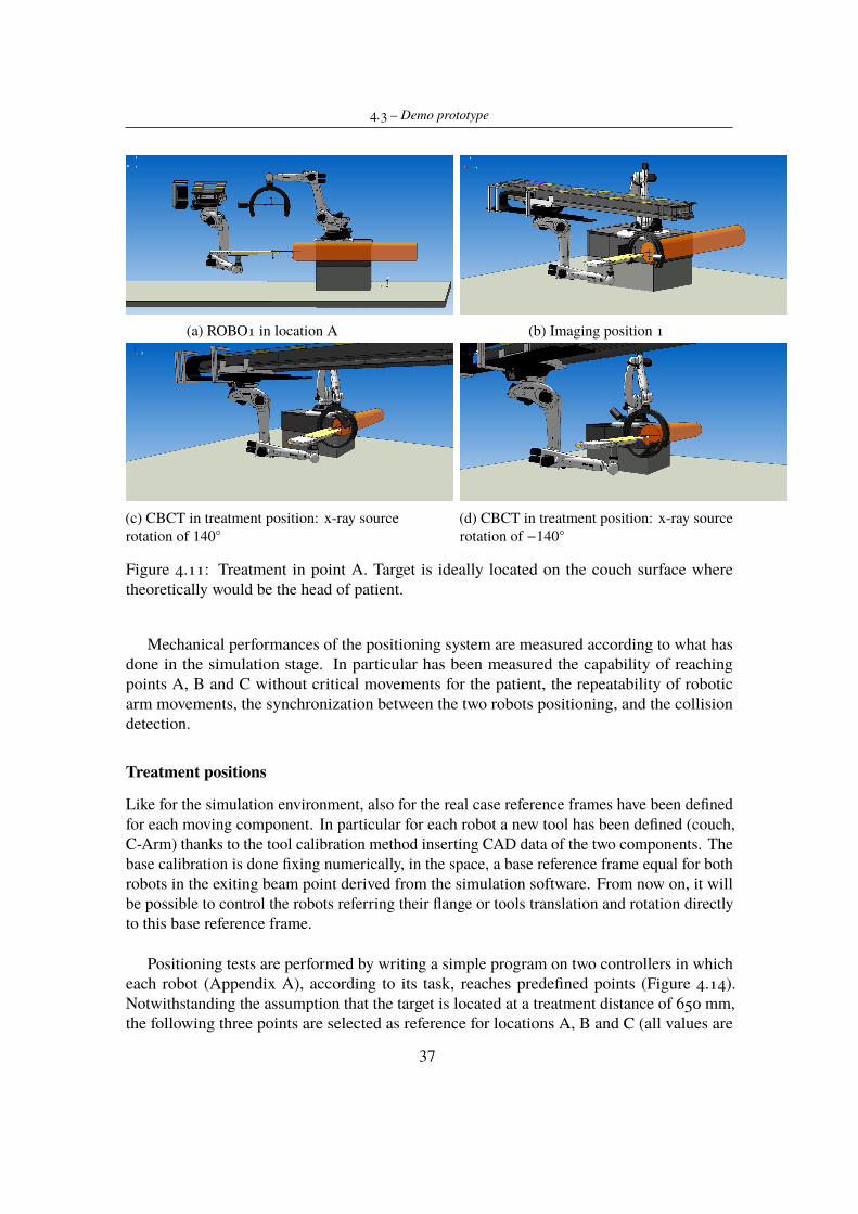
This new configuration allows to reach positions A, B and C with less and simpler movementsof the positioning robot. Furthermore, once ROBO2 reaches the treatment position, theremaining space inside the room can be used by ROBO1 in order to perform imaging taskswithout collide with other components (couch, ROBO2, beam nozzle). Imaging positionsare mainly two; this is due to the fact that the C-Arm position is the same both for PositionB and C. Observe that, during C-ring rotation, the C-Arm and the robotic arm are kept fixin order to increase high position accuracy for the X-ray tube and imager, except for smalladjustments to compensate the flexibility of the structure. Position A is the easiest situationfor the system, since the C-ring can perform a complete 360◦ rotation (Figure 4.11). For whatconcerns positions B and C there are limitations in the C-ring rotation due to the presence ofthe beam nozzle; that’s why was estimated for the x-ray source a possible rotation of ±140◦around the y axis of the C-ring RF from the starting position, avoiding that it hits the beamnozzle. Theoretically this rotation would be sufficient in order to reconstruct a 3D computedtomography in accordance with the considerations discussed in Section 4.1.3.
4.3 Demo prototypeOnce simulation gave satisfactory results, the attention has been focused on the real environ-ment. As said before, this is only a demo prototype so the same elements (couch, C shaped
35
4 – RPPS development
(a) Front view (b) Rear view
(c) Side view
Figure 4.9: Load position in simulating environment with highlighted reference frames foreach component.
Figure 4.10: Load position of real suite in the ITEL Mechatronic laboratory.
arm, beam nozzle) are as well as possible simulated. The main objective is to demonstratewhether the designed configuration is a viable option in reality.
36
4.3 – Demo prototype
(a) ROBO1 in location A (b) Imaging position 1
(c) CBCT in treatment position: x-ray sourcerotation of 140◦
(d) CBCT in treatment position: x-ray sourcerotation of −140◦
Figure 4.11: Treatment in point A. Target is ideally located on the couch surface wheretheoretically would be the head of patient.
Mechanical performances of the positioning system are measured according to what hasdone in the simulation stage. In particular has been measured the capability of reachingpoints A, B and C without critical movements for the patient, the repeatability of roboticarm movements, the synchronization between the two robots positioning, and the collisiondetection.
Treatment positions
Like for the simulation environment, also for the real case reference frames have been definedfor each moving component. In particular for each robot a new tool has been defined (couch,C-Arm) thanks to the tool calibration method inserting CAD data of the two components. Thebase calibration is done fixing numerically, in the space, a base reference frame equal for bothrobots in the exiting beam point derived from the simulation software. From now on, it willbe possible to control the robots referring their flange or tools translation and rotation directlyto this base reference frame.
Positioning tests are performed by writing a simple program on two controllers in whicheach robot (Appendix A), according to its task, reaches predefined points (Figure 4.14).Notwithstanding the assumption that the target is located at a treatment distance of 650 mm,the following three points are selected as reference for locations A, B and C (all values are
37
4 – RPPS development
(a) ROBO1 in location B (b) Imaging position 2
(c) CBCT in treatment position: x-ray sourcerotation of 140◦
(d) CBCT in treatment position: x-ray sourcerotation of −140◦ (rear view)
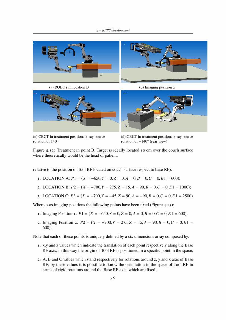
Figure 4.12: Treatment in point B. Target is ideally located 10 cm over the couch surfacewhere theoretically would be the head of patient.
relative to the position of Tool RF located on couch surface respect to base RF):
1. LOCATION A: P1 = (X = −650,Y = 0, Z = 0, A = 0,B = 0,C = 0,E1 = 600);
2. LOCATION B: P2 = (X = −700,Y = 275, Z = 15, A = 90,B = 0,C = 0,E1 = 1000);
3. LOCATION C: P3 = (X = −700,Y = −45, Z = 90, A = −90,B = 0,C = 0,E1 = 2500).
Whereas as imaging positions the following points have been fixed (Figure 4.15):
1. Imaging Position 1: P1 = (X = −650,Y = 0, Z = 0, A = 0,B = 0,C = 0,E1 = 600);
2. Imaging Position 2: P2 = (X = −700,Y = 275, Z = 15, A = 90,B = 0,C = 0,E1 =600).
Note that each of these points is uniquely defined by a six dimensions array composed by:
1. x,y and z values which indicate the translation of each point respectively along the BaseRF axis; in this way the origin of Tool RF is positioned in a specific point in the space;
2. A, B and C values which stand respectively for rotations around z, y and x axis of BaseRF; by these values it is possible to know the orientation in the space of Tool RF interms of rigid rotations around the Base RF axis, which are fixed;
38
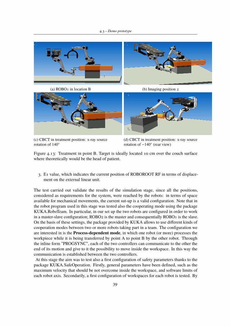
4.3 – Demo prototype
(a) ROBO1 in location B (b) Imaging position 2
(c) CBCT in treatment position: x-ray sourcerotation of 140◦
(d) CBCT in treatment position: x-ray sourcerotation of −140◦ (rear view)
Figure 4.13: Treatment in point B. Target is ideally located 10 cm over the couch surfacewhere theoretically would be the head of patient.
3. E1 value, which indicates the current position of ROBOROOT RF in terms of displace-ment on the external linear unit.
The test carried out validate the results of the simulation stage, since all the positions,considered as requirements for the system, were reached by the robots: in terms of spaceavailable for mechanical movements, the current sut-up is a valid configuration. Note that inthe robot program used in this stage was tested also the cooperating mode using the packageKUKA.RoboTeam. In particular, in our set up the two robots are configured in order to workin a master-slave configuration; ROBO2 is the master and consequentially ROBO1 is the slave.On the basis of these settings, the package provided by KUKA allows to use different kinds ofcooperation modes between two or more robots taking part in a team. The configuration weare interested in is the Process-dependent mode, in which one robot (or more) processes theworkpiece while it is being transferred by point A to point B by the other robot. Throughthe inline form "PROGSYNC", each of the two controllers can communicate to the other theend of its motion and give to it the possibility to move inside the workspace. In this way thecommunication is established between the two controllers.At this stage the aim was to test also a first configuration of safety parameters thanks to the
package KUKA.SafeOperation. Firstly, general parameters have been defined, such as themaximum velocity that should be not overcome inside the workspace, and software limits ofeach robot axis. Secondarily, a first configuration of workspaces for each robot is tested. By
39
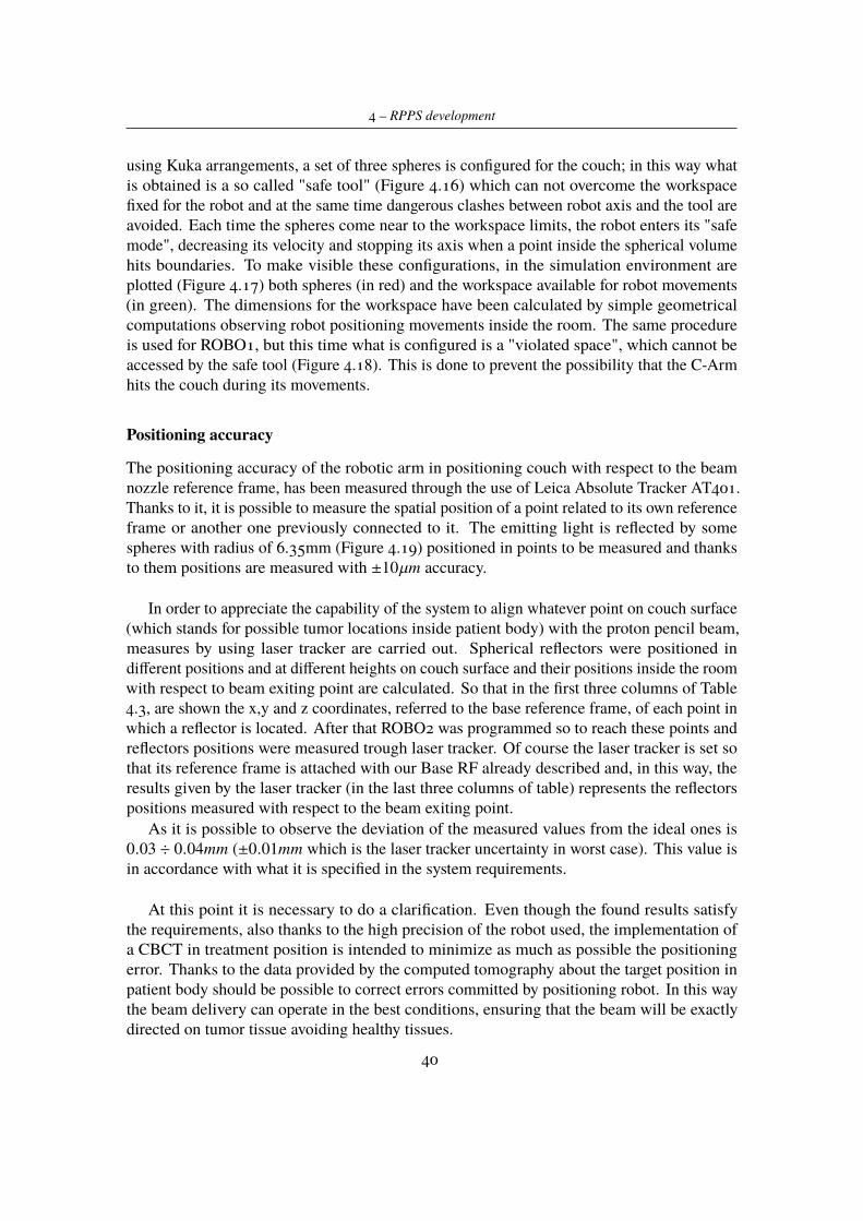
4 – RPPS development
using Kuka arrangements, a set of three spheres is configured for the couch; in this way whatis obtained is a so called "safe tool" (Figure 4.16) which can not overcome the workspacefixed for the robot and at the same time dangerous clashes between robot axis and the tool areavoided. Each time the spheres come near to the workspace limits, the robot enters its "safemode", decreasing its velocity and stopping its axis when a point inside the spherical volumehits boundaries. To make visible these configurations, in the simulation environment areplotted (Figure 4.17) both spheres (in red) and the workspace available for robot movements(in green). The dimensions for the workspace have been calculated by simple geometricalcomputations observing robot positioning movements inside the room. The same procedureis used for ROBO1, but this time what is configured is a "violated space", which cannot beaccessed by the safe tool (Figure 4.18). This is done to prevent the possibility that the C-Armhits the couch during its movements.
Positioning accuracy
The positioning accuracy of the robotic arm in positioning couch with respect to the beamnozzle reference frame, has been measured through the use of Leica Absolute Tracker AT401.Thanks to it, it is possible to measure the spatial position of a point related to its own referenceframe or another one previously connected to it. The emitting light is reflected by somespheres with radius of 6.35mm (Figure 4.19) positioned in points to be measured and thanksto them positions are measured with ±10µm accuracy.
In order to appreciate the capability of the system to align whatever point on couch surface(which stands for possible tumor locations inside patient body) with the proton pencil beam,measures by using laser tracker are carried out. Spherical reflectors were positioned indifferent positions and at different heights on couch surface and their positions inside the roomwith respect to beam exiting point are calculated. So that in the first three columns of Table4.3, are shown the x,y and z coordinates, referred to the base reference frame, of each point inwhich a reflector is located. After that ROBO2 was programmed so to reach these points andreflectors positions were measured trough laser tracker. Of course the laser tracker is set sothat its reference frame is attached with our Base RF already described and, in this way, theresults given by the laser tracker (in the last three columns of table) represents the reflectorspositions measured with respect to the beam exiting point.
As it is possible to observe the deviation of the measured values from the ideal ones is0.03 ÷ 0.04mm (±0.01mm which is the laser tracker uncertainty in worst case). This value isin accordance with what it is specified in the system requirements.
At this point it is necessary to do a clarification. Even though the found results satisfythe requirements, also thanks to the high precision of the robot used, the implementation ofa CBCT in treatment position is intended to minimize as much as possible the positioningerror. Thanks to the data provided by the computed tomography about the target position inpatient body should be possible to correct errors committed by positioning robot. In this waythe beam delivery can operate in the best conditions, ensuring that the beam will be exactlydirected on tumor tissue avoiding healthy tissues.
40
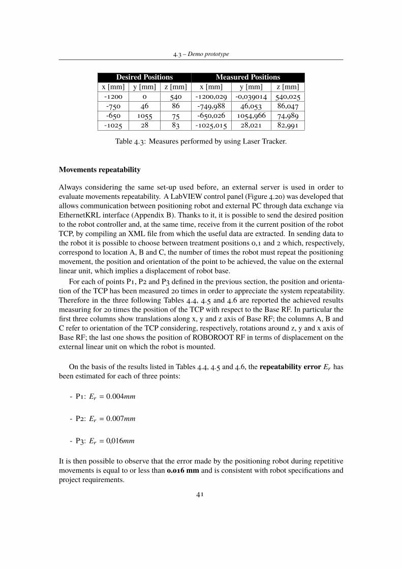
4.3 – Demo prototype
Desired Positions Measured Positionsx [mm] y [mm] z [mm] x [mm] y [mm] z [mm]-1200 0 540 -1200,029 -0,039014 540,025-750 46 86 -749,988 46,053 86,047-650 1055 75 -650,026 1054,966 74,989-1025 28 83 -1025,015 28,021 82,991
Table 4.3: Measures performed by using Laser Tracker.
Movements repeatability
Always considering the same set-up used before, an external server is used in order toevaluate movements repeatability. A LabVIEW control panel (Figure 4.20) was developed thatallows communication between positioning robot and external PC through data exchange viaEthernetKRL interface (Appendix B). Thanks to it, it is possible to send the desired positionto the robot controller and, at the same time, receive from it the current position of the robotTCP, by compiling an XML file from which the useful data are extracted. In sending data tothe robot it is possible to choose between treatment positions 0,1 and 2 which, respectively,correspond to location A, B and C, the number of times the robot must repeat the positioningmovement, the position and orientation of the point to be achieved, the value on the externallinear unit, which implies a displacement of robot base.
For each of points P1, P2 and P3 defined in the previous section, the position and orienta-tion of the TCP has been measured 20 times in order to appreciate the system repeatability.Therefore in the three following Tables 4.4, 4.5 and 4.6 are reported the achieved resultsmeasuring for 20 times the position of the TCP with respect to the Base RF. In particular thefirst three columns show translations along x, y and z axis of Base RF; the columns A, B andC refer to orientation of the TCP considering, respectively, rotations around z, y and x axis ofBase RF; the last one shows the position of ROBOROOT RF in terms of displacement on theexternal linear unit on which the robot is mounted.
On the basis of the results listed in Tables 4.4, 4.5 and 4.6, the repeatability error Er hasbeen estimated for each of three points:
- P1: Er = 0.004mm
- P2: Er = 0.007mm
- P3: Er = 0,016mm
It is then possible to observe that the error made by the positioning robot during repetitivemovements is equal to or less than 0.016 mm and is consistent with robot specifications andproject requirements.
41
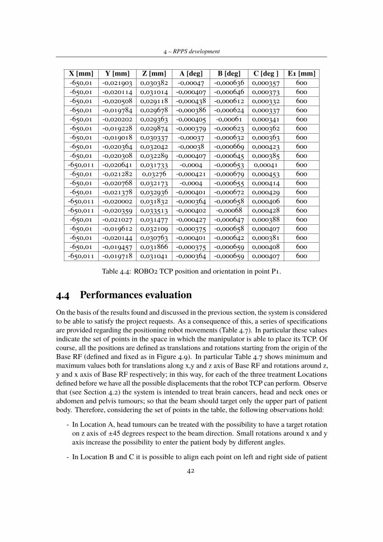
4 – RPPS development
X [mm] Y [mm] Z [mm] A [deg] B [deg] C [deg ] E1 [mm]-650,01 -0,021903 0,030382 -0,00047 -0,000636 0,000357 600-650,01 -0,020114 0,031014 -0,000407 -0,000646 0,000373 600-650,01 -0,020508 0,029118 -0,000438 -0,000612 0,000332 600-650,01 -0,019784 0,029678 -0,000386 -0,000624 0,000337 600-650,01 -0,020202 0,029363 -0,000405 -0,00061 0,000341 600-650,01 -0,019228 0,029874 -0,000379 -0,000623 0,000362 600-650,01 -0,019018 0,030337 -0,00037 -0,000632 0,000363 600-650,01 -0,020364 0,032042 -0,00038 -0,000669 0,000423 600-650,01 -0,020308 0,032289 -0,000407 -0,000645 0,000385 600-650,011 -0,020641 0,031733 -0,0004 -0,000653 0,00041 600-650,01 -0,021282 0,03276 -0,000421 -0,000679 0,000453 600-650,01 -0,020768 0,032173 -0,0004 -0,000655 0,000414 600-650,01 -0,021378 0,032936 -0,000401 -0,000672 0,000429 600-650,011 -0,020002 0,031832 -0,000364 -0,000658 0,000406 600-650,011 -0,020359 0,033513 -0,000402 -0,00068 0,000428 600-650,01 -0,021027 0,031477 -0,000427 -0,000647 0,000388 600-650,01 -0,019612 0,032109 -0,000375 -0,000658 0,000407 600-650,01 -0,020144 0,030763 -0,000401 -0,000642 0,000381 600-650,01 -0,019457 0,031866 -0,000375 -0,000659 0,000408 600-650,011 -0,019718 0,031041 -0,000364 -0,000659 0,000407 600
Table 4.4: ROBO2 TCP position and orientation in point P1.
4.4 Performances evaluationOn the basis of the results found and discussed in the previous section, the system is consideredto be able to satisfy the project requests. As a consequence of this, a series of specificationsare provided regarding the positioning robot movements (Table 4.7). In particular these valuesindicate the set of points in the space in which the manipulator is able to place its TCP. Ofcourse, all the positions are defined as translations and rotations starting from the origin of theBase RF (defined and fixed as in Figure 4.9). In particular Table 4.7 shows minimum andmaximum values both for translations along x,y and z axis of Base RF and rotations around z,y and x axis of Base RF respectively; in this way, for each of the three treatment Locationsdefined before we have all the possible displacements that the robot TCP can perform. Observethat (see Section 4.2) the system is intended to treat brain cancers, head and neck ones orabdomen and pelvis tumours; so that the beam should target only the upper part of patientbody. Therefore, considering the set of points in the table, the following observations hold:
- In Location A, head tumours can be treated with the possibility to have a target rotationon z axis of ±45 degrees respect to the beam direction. Small rotations around x and yaxis increase the possibility to enter the patient body by different angles.
- In Location B and C it is possible to align each point on left and right side of patient
42
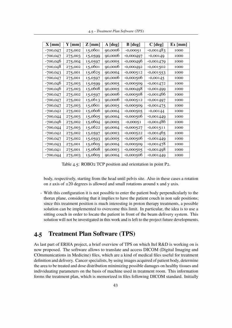
4.5 – Treatment Plan Software (TPS)
X [mm] Y [mm] Z [mm] A [deg] B [deg] C [deg] E1 [mm]-700,047 275,002 15,0601 90,0006 -0,00051 -0,001483 1000-700,047 275,003 15,0599 90,0006 -0,000497 -0,00149 1000-700,046 275,004 15,0597 90,0005 -0,000496 -0,001479 1000-700,048 275,002 15,0601 90,0006 -0,000492 -0,001502 1000-700,043 275,001 15,0625 90,0004 -0,000512 -0,001553 1000-700,047 275,001 15,0597 90,0006 -0,000506 -0,00145 1000-700,046 275,003 15,0599 90,0005 -0,000509 -0,001472 1000-700,046 275,003 15,0608 90,0005 -0,000498 -0,001499 1000-700,047 275,002 15,0597 90,0006 -0,000508 -0,001466 1000-700,047 275,002 15,0613 90,0006 -0,000512 -0,001497 1000-700,047 275,003 15,0601 90,0005 -0,000509 -0,001475 1000-700,042 275,002 15,0606 90,0004 -0,000505 -0,00144 1000-700,044 275,003 15,0605 90,0004 -0,000506 -0,001449 1000-700,046 275,002 15,0604 90,0005 -0,00051 -0,001486 1000-700,044 275,003 15,0622 90,0004 -0,000527 -0,001511 1000-700,042 275,002 15,0597 90,0003 -0,000522 -0,001465 1000-700,047 275,002 15,0593 90,0005 -0,000506 -0,001449 1000-700,043 275,001 15,0605 90,0004 -0,000509 -0,001478 1000-700,041 275,001 15,0608 90,0003 -0,000505 -0,001498 1000-700,044 275,003 15,0605 90,0004 -0,000506 -0,001449 1000
Table 4.5: ROBO2 TCP position and orientation in point P2.
body, respectively, starting from the head until pelvis site. Also in these cases a rotationon z axis of ±20 degrees is allowed and small rotations around x and y axis.
- With this configuration it is not possible to enter the patient body perpendicularly to thethorax plane, considering that it implies to have the patient couch in non safe positions;since this treatment position is much interesting in proton therapy treatments, a possiblesolution can be implemented to overcome this limit. In particular, the idea is to use asitting couch in order to locate the patient in front of the beam delivery system. Thissolution will not be investigated in this work and is left to the project future developments.
4.5 Treatment Plan Software (TPS)As last part of ERHA project, a brief overview of TPS on which Itel R&D is working on isnow proposed. The software allows to translate and access DICOM (Digital Imaging andCOmmunications in Medicine) files, which are a kind of medical files useful for treatmentdefinition and delivery. Cancer specialists, by using images acquired of patient body, determinethe area to be treated and dose distribution minimizing possible damages on healthy tissues andindividuating parameters on the basis of machine used in treatment room. This informationforms the treatment plan, which is memorized in files following DICOM standard. Initially
43
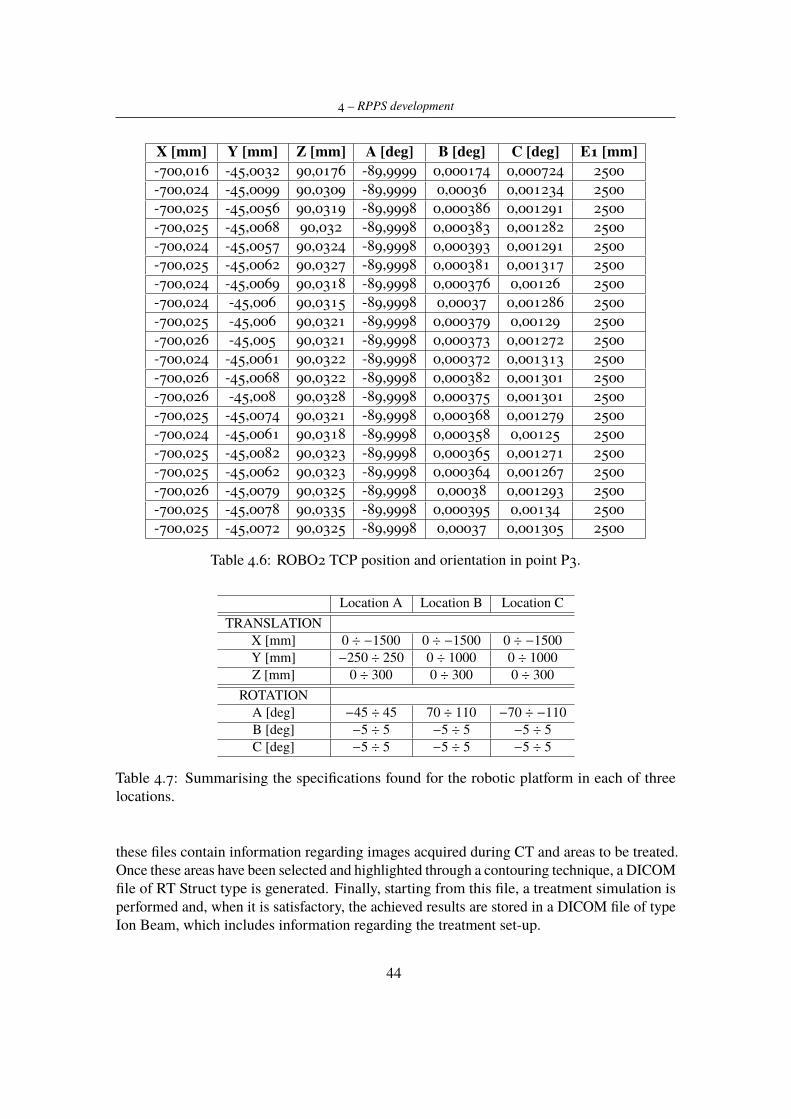
4 – RPPS development
X [mm] Y [mm] Z [mm] A [deg] B [deg] C [deg] E1 [mm]-700,016 -45,0032 90,0176 -89,9999 0,000174 0,000724 2500-700,024 -45,0099 90,0309 -89,9999 0,00036 0,001234 2500-700,025 -45,0056 90,0319 -89,9998 0,000386 0,001291 2500-700,025 -45,0068 90,032 -89,9998 0,000383 0,001282 2500-700,024 -45,0057 90,0324 -89,9998 0,000393 0,001291 2500-700,025 -45,0062 90,0327 -89,9998 0,000381 0,001317 2500-700,024 -45,0069 90,0318 -89,9998 0,000376 0,00126 2500-700,024 -45,006 90,0315 -89,9998 0,00037 0,001286 2500-700,025 -45,006 90,0321 -89,9998 0,000379 0,00129 2500-700,026 -45,005 90,0321 -89,9998 0,000373 0,001272 2500-700,024 -45,0061 90,0322 -89,9998 0,000372 0,001313 2500-700,026 -45,0068 90,0322 -89,9998 0,000382 0,001301 2500-700,026 -45,008 90,0328 -89,9998 0,000375 0,001301 2500-700,025 -45,0074 90,0321 -89,9998 0,000368 0,001279 2500-700,024 -45,0061 90,0318 -89,9998 0,000358 0,00125 2500-700,025 -45,0082 90,0323 -89,9998 0,000365 0,001271 2500-700,025 -45,0062 90,0323 -89,9998 0,000364 0,001267 2500-700,026 -45,0079 90,0325 -89,9998 0,00038 0,001293 2500-700,025 -45,0078 90,0335 -89,9998 0,000395 0,00134 2500-700,025 -45,0072 90,0325 -89,9998 0,00037 0,001305 2500
Table 4.6: ROBO2 TCP position and orientation in point P3.
Location A Location B Location CTRANSLATION
X [mm] 0 ÷ −1500 0 ÷ −1500 0 ÷ −1500Y [mm] −250 ÷ 250 0 ÷ 1000 0 ÷ 1000Z [mm] 0 ÷ 300 0 ÷ 300 0 ÷ 300
ROTATIONA [deg] −45 ÷ 45 70 ÷ 110 −70 ÷ −110B [deg] −5 ÷ 5 −5 ÷ 5 −5 ÷ 5C [deg] −5 ÷ 5 −5 ÷ 5 −5 ÷ 5
Table 4.7: Summarising the specifications found for the robotic platform in each of threelocations.
these files contain information regarding images acquired during CT and areas to be treated.Once these areas have been selected and highlighted through a contouring technique, a DICOMfile of RT Struct type is generated. Finally, starting from this file, a treatment simulation isperformed and, when it is satisfactory, the achieved results are stored in a DICOM file of typeIon Beam, which includes information regarding the treatment set-up.
44
4.5 – Treatment Plan Software (TPS)
The software realized by using LabVIEW has a tab structure in which all treatment plandefinition phases are available. Firstly, the different files forming the DICOM one must beloaded inside the software(Figure 4.21). The subsequent tab contains informations both forDICOM of type CT and the one of type RT Struct (Figure 4.22). On the left side it is possibleto visualize different CT images, which have been acquired at same time, while on the rightside the 3D file of RT Struct is visualized. Here it is possible to observe the tumor volumehighlighted by prefixed colour and other organs inside the area of interest. The navigationbetween the CT files and in 3D view are allowed by central panel. The last tab (Figure 4.23)reports all the treatment plan parameters: the point that must be hit by particles beam, theused algorithm, the number of slices in which the tumour was divided. In the right side areshowed all the points in tumour volume and their coordinates useful to direct the beam correctly.
This software must communicate with the robot control system so to uniquely define theposition of tumour inside patient body. It should be also used to receive CT files coming fromCBCT performed before treatment delivery, in order to validate and, eventually, correct thetreatment plan information.
45
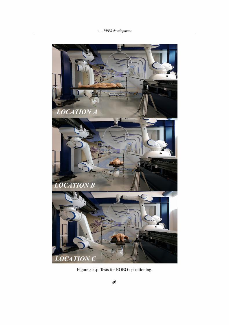
4 – RPPS development
Figure 4.14: Tests for ROBO1 positioning.
46
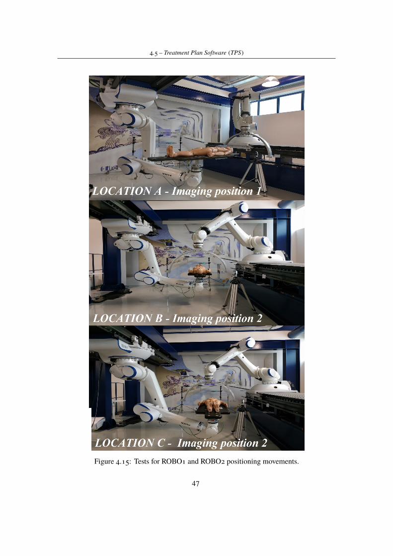
4.5 – Treatment Plan Software (TPS)
Figure 4.15: Tests for ROBO1 and ROBO2 positioning movements.
47
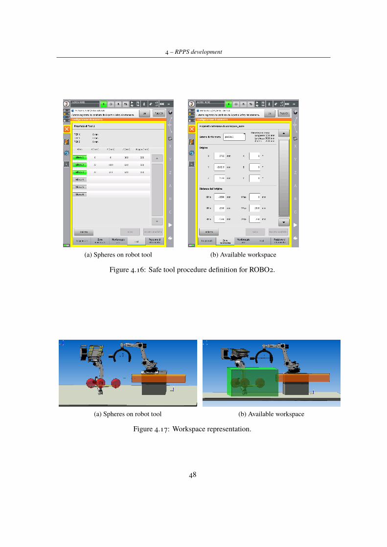
4 – RPPS development
(a) Spheres on robot tool (b) Available workspace
Figure 4.16: Safe tool procedure definition for ROBO2.
(a) Spheres on robot tool (b) Available workspace
Figure 4.17: Workspace representation.
48
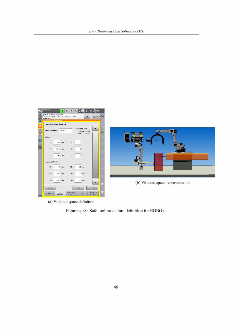
4.5 – Treatment Plan Software (TPS)
(a) Violated space definition
(b) Violated space representation
Figure 4.18: Safe tool procedure definition for ROBO2.
49
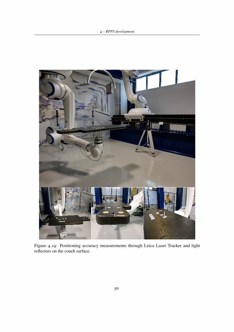
4 – RPPS development
Figure 4.19: Positioning accuracy measurements through Leica Laser Tracker and lightreflectors on the couch surface.
50
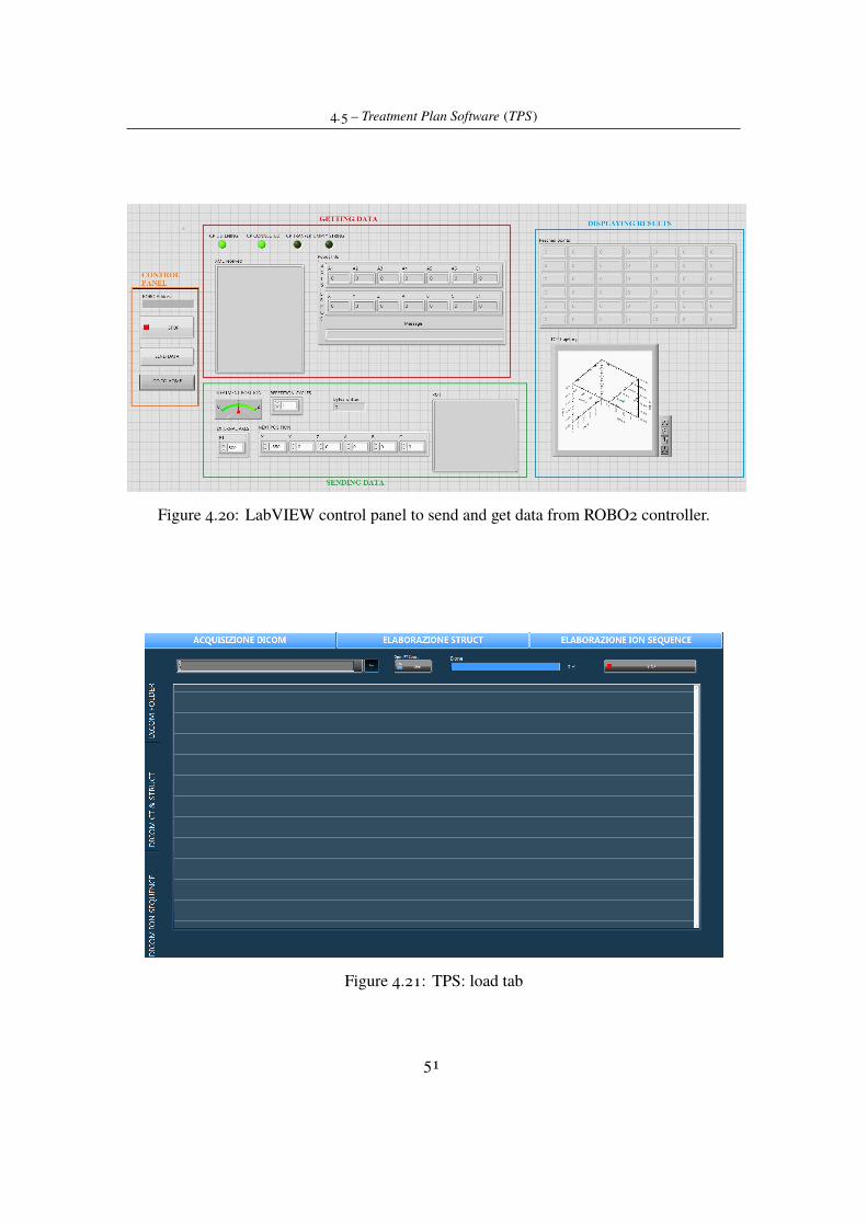
4.5 – Treatment Plan Software (TPS)
Figure 4.20: LabVIEW control panel to send and get data from ROBO2 controller.
Figure 4.21: TPS: load tab
51
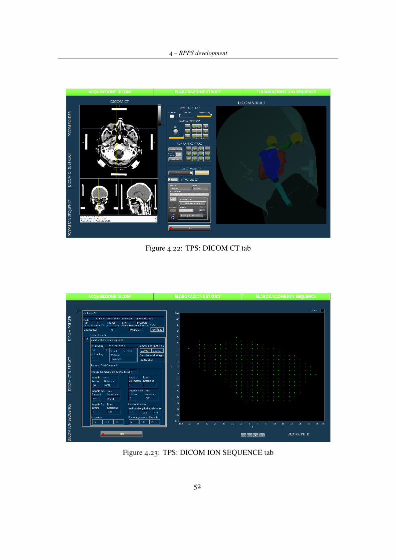
4 – RPPS development
Figure 4.22: TPS: DICOM CT tab
Figure 4.23: TPS: DICOM ION SEQUENCE tab
52
Chapter 5
Conclusions
On the basis of the initial considerations, the main goal of this project was to investigate thepossibility to have a robotised platform performing patient positioning tasks in proton therapydelivery treatments. Taking into account this main goal, Chapter 4 has firstly proposed apossible set up we have designed for that kind of application with all the needed componentsand specifications. Note that the proposed solution is just one of all the possible viable options.It was found considering what was the real simulating prototype available in Itel Lab, onwhich has been allowed performing experimental tests.
Results, coming from simulations, show that the proposed solution satisfies requirementsin terms of space occupancy, and that the manipulator is able to reach the considered treatmentpositions. As proof of this, specifications about available positioning points, provided inTable 4.7, are in accordance with tasks for which the system is designed to. Remember thatthe system has intended for treatments focused on head and neck cancers or on abdomenand pelvis ones; that is why the points reported in the previous table were tested and used asspecifications for the whole system. Of course, not all of the points and angles on the patientbody are achievable with this system, since the beam direction is fixed and the patient couchcan not be rotated in any direction preventing possible risks for the person. So that, it wasthough to equip the positioning system also with a sitting couch, thanks to which the patientcan be aligned in many other different ways with the beam. However, it was not possible totest also this configuration, so it will remain as a possible future development to improve theRPPS efficiency.
Moreover these tests have demonstrated that the idea to use a second manipulator to performa computed tomography in treatment position is a realistic possibility. In fact, considering theproposed set up, the simulations described in Section 4.3 show how it is possible to performpositioning tasks and imaging tasks in the same room with two different robots cooperatingeach other.
Another crucial point in the validation of the system was to appreciate the precision it ispossible to achieve with our configuration. As already said, proton therapy and, in general,all radiation therapies have many advantages on patient health, but they must have a high
53
5 – Conclusions
precision degree in beam delivery. Also from this side, as shown in Section 4.3, experimentaltests were performed achieving satisfying results:
- the position is more accurate than in the expected worst case and, in addition, thisparameter has to be still well appreciated, since it could be minimized by introducingimaging guidance operations;
- the movements repeatability, also thanks to the characteristics of the employed ma-nipulator, satisfies the project requirements and ensures high precision in repetitivemovements.
Summarising, the proposed design for RPPS system is a good solution in terms of requestedperformances. The work done during this period has demonstrated that it is possible to usethe two anthropomorphic arms in order to produce a more compact and cheaper system. Ofcourse, the system needs to be improved and tested again. As future developments the realsystem for the computed tomography should be implemented and its benefits in imagingguidance verified in order to improve the ability of the system to align tumor target with theparticles beam. Moreover, the TPS software should be integrated with the robot controller inorder to test a real treatment plan on the robot platform.
54

Bibliography
[1] David AJaffray,Ph.D.,Jeffrey H. Siewerdsen, Ph.D., John WWong, Ph.D., AlvaroAMartinez, M.D., Flat-panel cone-beam computed tomography for image-guided radiationtherapy,Int J Radiat Oncol Biol Phys. 2002 Aug 1;53(5):1337-49.
[2] Pauwels R, Araki K, Siewerdsen JH, Thongvigitmanee SS., Technical aspects of dentalCBCT: state of the art, Dentomaxillofac Radiol. 2015;44(1):20140224.
[3] Ruben Pauwels, What Is CBCT and How Does It Work?, Springer International PublishingAG 2018.
[4] William C. Scarfe, BDS, FRACDS, MSa, Allan G. Farman, BDS, PhD, DSc, MBA, Whatis Cone-Beam CT and How Does it Work?, Dent Clin N Am 52 (2008) 707–730.
[5] Dirk De Ruysscher, Edmond Sterpin, Karin Haustermans and Tom Depuydt TumourMovement in Proton Therapy: Solutions and Remaining Questions: A Review, Cancers(Basel). 2015 Sep; 7(3): 1143–1153.
[6] Hua, C.; Yao, W.; Kidani, T.; Tomida, K.; Ozawa, S.; Nishimura, T.; Fujisawa, T.;Shinagawa, R.; Merchant, T.E. A robotic C-arm cone beam CT system for imageguidedproton therapy: Design and performance, British Journal of Radiology, 2017, Vol.90(1079)
[7] Melissa A.L. Vyfhuis, Nasarachi Onyeuku, Tejan Diwanji, Sina Mossahebi, Neha P.Amin, Shahed N. Badiyan, Pranshu Mohindra and Charles B. Simone II Advances inproton therapy in lung cancer, Ther Adv Respir Dis 2018, Vol. 12: 1–16
[8] James Welsh, M.D., Daniel Gomez, M.D., Matthew B. Palmer, M.B.A., C.M.D, BeverlyA. Riley, C.M.D., Amin V Mayankkumar, C.M.D., Ritsuko Komaki, M.D. , Lei Dong,Ph.D., X.Ronald Zhu, Ph.D., Anna Likhacheva, M.D., Zhongxing Liao, M.D., Wayne L.Hofstetter, M.D., Jaffer A. Ajani, M.D., and James D. Cox, M.D. Intensity-ModulatedProton Therapy Further Reduces Normal Tissue Exposure During Definitive Therapy forLocally Advanced Distal Esophageal Tumors: A Dosimetric Study , Int J Radiat Oncol BiolPhys. 2011 December 1; 81(5): 1336–1342.
[9] Wayne D Newhauser and Rui Zhang, The physics of proton therapy, Phys Med Biol. 2015
55

Bibliography
April 21; 60(8): R155–R209.
[10] www.kuka.com
[11] G. Kraft, Tumor Therapy with Heavy Charged Particles, Progress in Particle and NuclearPhysics 45 (2000) S473-S544.
[12] George B. Coutrakon, Accelerators for Heavy-charged-particle Radiation Therapy,Technology in Cancer Research and Treatment ISSN 1533-0346, Volume 6, Number 4Supplement, August 2007.
[13] A.V. Klyachko, GEM-based Dose Imaging Detectors for Proton Therapy QualityAssurance and Proton Radiography, Quarterly Physics Review, Vol. 3, Issue 3, October 2017
[14] Luigi Picardi, Concetta Ronsivalle, Angelo Vignati, Progetto del TOP LINAC, 1997
[15] El-Saftawy, Ashraf, Regulating the performance parameters of accelerated particles,2013
[16] Coutrakon G., Slater J.M., Ghebremedhin A., Design considerations for medical protonaccelerators, Proceedings of the 1999 Particle Accelerator Conference, 0 1999, Vol.1,pp.11-15
[17] T Haberer, W Becher, D Schardt et al., Magnetic scanning system for heavy ion therapy,NIM A, 1993, 330, 296.
56
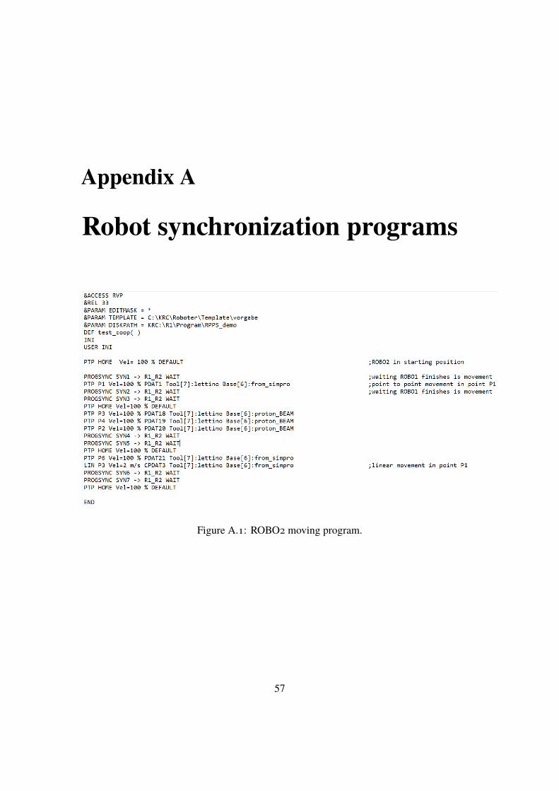
Appendix A
Robot synchronization programs
Figure A.1: ROBO2 moving program.
57
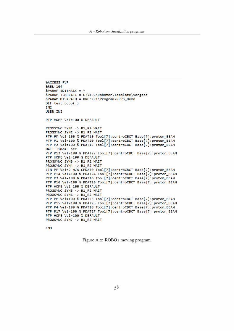
A – Robot synchronization programs
Figure A.2: ROBO1 moving program.
58
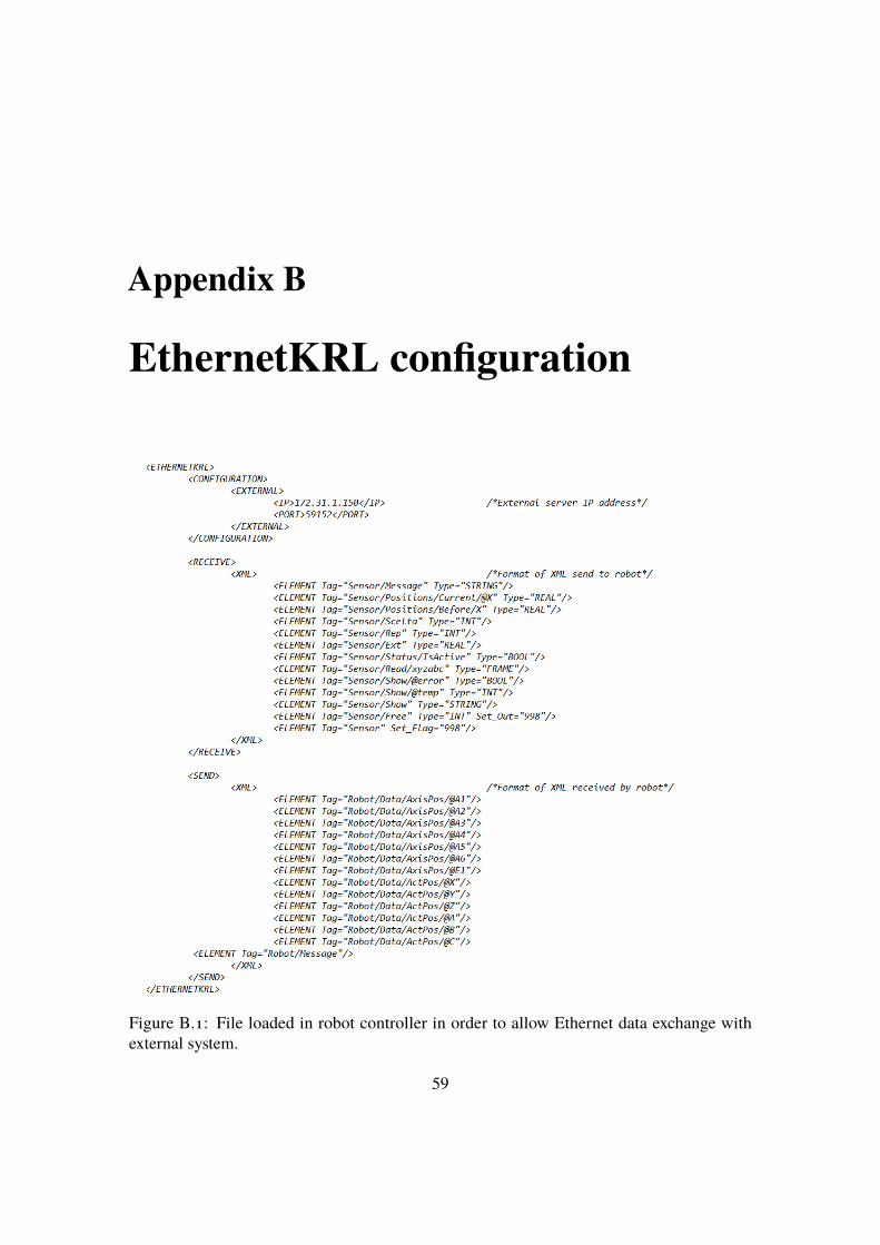
Appendix B
EthernetKRL configuration
Figure B.1: File loaded in robot controller in order to allow Ethernet data exchange withexternal system.
59
Related Documents