7295-026A Issue: 02-2000 USER'S MANUAL MSHF MAST CLIMBING WORK PLATFORM This manual is assigned to:

Welcome message from author
This document is posted to help you gain knowledge. Please leave a comment to let me know what you think about it! Share it to your friends and learn new things together.
Transcript

7295-026AIssue: 02-2000
USER'S MANUAL
MSHFMAST CLIMBING WORK PLATFORM
This manual is assigned to:

II MSHF • 7295-026A
© 2000, HEK Manufacturing BV., Middelbeers, The Netherlands
Nothing contained in this publication may be copied, and/or published by means ofprinting, photocopying, microfilm or any other method without prior written permission fromHEK Manufacturing B.V.

IIIMSHF • 7295-026A
HEK Manufacturing B.V.Westelbeersedijk 18 P.O. box 25091 SM Middelbeers 5090 AA MiddelbeersThe Netherlands The NetherlandsTel : +31 13 51 48 653Fax : +31 13 51 48 630

IV MSHF • 7295-026A

VMSHF • 7295-026A
FOREWORD
FOREWORD
The mast climbing work platform isprovided with a rack and pinion drive.
The mast climbing work platform can bequickly moved and is easy to transport.
The mast climbing work platform can befitted with one or two masts and can befreestanding or anchored.
The mast, which consists of separateelements, can easily be adjusted inheight to match the height of the buildingwork. The mast is easy to assemble fromthe platform.
Read this instruction manual carefully before using themast climbing work platform. Take all the safetyprecautions as described in chapter 3 into account.
The platform can be adjusted to theshape of the façade.The MSHF mast climbing work platformhas a control system which makes itpossible to stop at any desired height.
Every care has been taken in theconstruction of the mast climbing workplatform to ensure that all safety aspectshave been considered.
Depending on the application area, achoice can be made from differentplatform lengths, platform widths andpermissible loading.
This instruction manual describes onlythe basic machine, in the standard formsupplied by HEK Manufacturing BV.

VI MSHF • 7295-026A
CONTENTS
CONTENTS
FOREWORD V
CONTENTS VI
SURVEY OF ILLUSTRATIONS VII
EC DECLARATION OF CONFORMITY VIII
MEANING OF THE SYMBOLS USED IX
1. TECHNICAL DETAILS 1-11.1 General 1-11.2 Electrical installation 1-51.3 Drive unit 1-51.4 Chassis 1-71.5 Ground frame 1-71.6 Platform construction 1-81.6.1 Symmetrical platform construction 1-81.7 Loading of the mast climbing
work platform 1-101.7.1 Outriggers chassis 1-101.7.2 Single mast machine 1-111.7.3 Twin mast machine 1-121.8 Anchorforces 1-14
2. COMPONENT DESCRIPTION 2-12.1 General description 2-1
3. SAFETY 3-13.1 General 3-13.2 Safety prior to use 3-13.3 Safety in use 3-13.4 Safety after use 3-33.5 Built-in and additional safety features 3-3
4. TRANSPORT 4-14.1 Repositioning on the building site 4-24.2 Chassis drive unit 4-34.3 Repositioning with a crane 4-4
5. CONTROL COMPONENTS 5-15.1 Power supply socket for the drive unit 5-15.2 Power supply socket for the chassis 5-15.3 Platform control box 5-2
6. ASSEMBLY AND ANCHORING 6-16.1 Preparation for assembly 6-26.2 Ground support 6-36.3 Positioning the mast climbing
work platform 6-46.3.1 Mast climbing work platform with
single mast on a chassis 6-56.3.2 Mast climbing work platform with
one mast on a ground frame 6-66.3.3 Mast climbing work platform with
two masts on a chassis 6-86.3.4 Mast climbing work platform with
two masts on ground frames 6-116.4 Assembly of the mast 6-146.5 Anchoring the mast 6-176.6 Adjusting the platform width 6-196.7 Setting the machine left or right 6-216.8 Checking and adjusting the
lower striker plates 6-226.9 Checking the autolevel switches 6-236.10 Adjusting the EMOS system 6-246.11 Lightning protection 6-24
7. OPERATION 7-17.1 General 7-17.2 Preparation 7-17.3 Testing 7-37.4 Brake test 7-37.5 Operation from the platform 7-47.6 Operation in an emergency situation 7-47.7 Eccentric overload device 7-6
8. DISASSEMBLY AND TRANSPORT 8-1
9. MAINTENANCE 9-19.1 General 9-19.2 Maintenance intervals 9-19.3 Autolevel mechanism check 9-39.4 The motor brake 9-39.4.1 Operation 9-49.4.2 Maintenance 9-5
10. MALFUNCTION ANALYSIS 10-1
11. MACHINE DISPOSAL 11-1
12. LIST OF KEYWORDS 12-1
APPENDICES 1

VIIMSHF • 7295-026A
CONTENTS
SURVEY OF ILLUSTRATIONS
Fig.1 Dimensions XFig.1-1 Mast element 1-2Fig.1-2 Platform element 1-2Fig.1-3 Plug-in fence 1-2Fig.1-4 End fence 1-2Fig.1-5 Corner post 1-2Fig.1-6 Drive unit 1-4Fig.1-7 Chassis 1-6Fig.1-8 Ground frame 1-6Fig.1-9 Outrigger locking 1-10Fig.1-10 Anchor forces 1-14Fig.2-1 Basic set MSHF chassis/
ground frame 2-1Fig.4-1 Transport MSHF 4-1Fig.4-2 Locking pin outrigger chassis 4-2Fig.4-3 Brake lever chassis 4-2Fig.4-4 Switch box chassis 4-3Fig.4-5 Control box chassis 4-3Fig.5-1 Power supply socket drive unit 5-1Fig.5-2 Power supply socket chassis 5-1Fig.5-3 Control box 5-2Fig.6-1 Position machine 6-1Fig.6-2 Ground support chassis 6-3Fig.6-3 Ground support ground frame 6-3Fig.6-4 Distance to the facade 6-4Fig.6-5 Locking pin outrigger chassis 6-5Fig.6-6 Autolevel locking pin 6-5Fig.6-7 Lower striker plate 6-5Fig.6-8 Lower striker plate 6-6Fig.6-9 Step 6-6Fig.6-10 Fence 6-6Fig.6-11 Gate safety switch 6-6Fig.6-12 Step 6-7Fig.6-13 Autolevel locking pin 6-7Fig.6-14 Fence 6-7Fig.6-15 Gate safety switch 6-7Fig.6-16 Locking pin outrigger chassis 6-8Fig.6-17 Autolevel locking pin 6-8Fig.6-18 Lower striker plate 6-8Fig.6-19 Step 6-9Fig.6-20 Fence 6-9Fig.6-21 Gate safety switch 6-10Fig.6-22 Autolevel locking pin 6-10Fig.6-23 Control cable dummy plug 6-10Fig.6-24 Autolevel locking pin 6-11Fig.6-25 Lower striker plate 6-11Fig.6-26 Gate safety switch 6-12Fig.6-27 Step 6-12Fig.6-28 Fence 6-12Fig.6-29 Autolevel locking pin 6-13Fig.6-30 Control cable dummy plug 6-13Fig.6-31 Power supply 6-14Fig.6-32 Main switch 6-14
Fig.6-33 Control buttons 6-15Fig.6-34 Proximity switch 6-15Fig.6-35 Red top mast element 6-16Fig.6-36 Mast cover 6-16Fig.6-37 Anchoring 6-19Fig.6-38 Outrigger platform extension 6-20Fig.6-39 Anchor ramp 6-20Fig.6-40 Machine setting left 6-21Fig.6-41 machine setting right 6-21Fig.6-42 switch left/right setting 6-21Fig.6-43 Adjusting lower striker plate 6-22Fig.6-44 Brake lever drive unit 6-23Fig.6-45 Autolevel switches 6-23Fig.6.46 Adjusting EMOS 6-24Fig.6-47 Lightning protection 6-25Fig.7-1 Main switch 7-2Fig.7-2 Emergency push-button 7-2Fig.7-3 Brake lever drive unit 7-3Fig.7-4 Push-buttons control box 7-4Fig.7-5 Drive unit brake release 7-5Fig.7-6 Signal light 7-6Fig.8-1 Drive unit brake release 8-1Fig.8-2 Autolevel locking locking pin 8-2Fig.8-3 Control cable dummy plug 8-2Fig.8-4 Securing outrigger 8-2Fig.8-5 Bundle platform elements 8-3Fig.8-6 Locking pin outrigger 8-3Fig.9-1 Drive unit brake release 9-3Fig.9-2 Motorbrake 9-4Fig.9-3 Motorbrake 9-5

VIII MSHF • 7295-026A
EC DECLARATION OF CONFORMITY
EC declaration of conformity for machines(pursuant to Annex IIa of the Machine Directives 89/392/EEC)
We, HEK Manufacturing bvWestelbeersedijk 185091 SM MiddelbeersThe Netherlands
hereby declare that, on the basis of its design and construction, the mast climbing workplatform named below and brought into circulation by us conform to the relevant basicsafety and health requirements contained in the EC Machine Directives.
Changes made to the machine without our consent invalidate this declaration.
This declaration applies to the mast climbing work platform:
HEK MSHF
In accordance with: EC Machine Directives 89/392/EG, Annex IV
EC number: 08/205/A 16-4912B, 1-7-1996
Certified by (‘Notified Body’): TÜV HANNOVER/SACHSEN ANHALT E.V.HANNOVER, GERMANY
Date/Manufacturer’s signature: Middelbeers, the Netherlands,November 1st 1999
Signatory: P.M. Blom, deputy manager

IXMSHF • 7295-026A
MEANING OF THE SYMBOLS USED
WARNINGFailing to (exactly) comply withthe working or operatinginstructions may lead to seriousinjury, fatal accident, severemechanical damage oroperating losses.
During use, no person may standunder the machine.
Danger: High voltage.
Danger of falling objects.
SYMBOLS

X MSHF • 7295-026A
Fig.1 Dimensions

TECHNICAL DETAILS
1-1MSHF • 7295-026A
1. TECHNICAL DETAILS
1.1 General
Note:The details are based on standard applications. In special situations, it may be possibleto deviate from these. This may only be done with the prior written approval of thesupplier.
For accessories and options see the accessory book.
Description MSHF 1 mast MSHF 2 masts
Platform length 2.9 - 10.3 m 9.5 - 33.8 ft 8.5 - 23.5 m 27.9 - 77.1 ft
Platform width 1.5 - 2.5 m 4.9 - 8.2 ft 1.5 - 2.5 m 4.9 - 8.2 ft
Distance between mast centres ---- ---- 7.3 - 13.3 m 14.1 - 43.6 ft
Distance between anchors (B) 13 - 15 m 42.7 - 49.2 ft 13 - 15 m 42.7 - 49.2 ft
Max. mastheight free-standing (A) 20 m 65.6 ft 20 m 65.6 ft
Max. mastheight anchored (A) 150 m 492 ft 150 m 492 ft
Max. mastheight above last anchor (D) 8 m 26.2 ft 8 m 26.2 ft
Mast type VRK700 VRK700 VRK700 VRK700
Max. number of persons 3 3 6 6
Platform speed 7 m/min 23 ft/min 7 m/min 23 ft/min
Loading capacity see section1.7
see section1.7
see section1.7
see section1.7
Distance between cable guides 6 m 19.7 ft 6 m 19.7 ft
Height of first anchor for chassis (C) 15 m 49.2 ft 15 m 49.2 ft
Height of first anchor for ground frame (C) 3 m 9.8 ft 3 m 9.8 ft
Height of second anchor for ground frame 9 m 29.5 ft 9 m 29.5 ft
Height jacks chassis min - max (E) 0.67 - 0.97 m 2.2 - 3.0 ft 0.67 - 0.97 m 2.2 - 3.0 ft
Height platform incl. fence 1.1 m / 3.6 ft (F) 1.95 m 6.4 ft 1.95 m 6.4 ft
Height platform to deck (G) 0.83 m 2.7 ft 0.83 m 2.7 ft
Height fence 1.1 m / 3.6 ft to upper sidemast cover (H)
1.36 m 4.5 ft 1.36 m 4.5 ft

TECHNICAL DETAILS
1-2 MSHF • 7295-026A
Fig.1-1 Mast element Fig.1-4 End fence
Fig.1-5 Corner postFig.1-2 Platform element
Fig.1-3 Plug-in fence

TECHNICAL DETAILS
1-3MSHF • 7295-026A
Part l x b x h [mm] weight[kg]
No. ofbolts
bolt dim. &quality
torque[Nm]
other
Mast element 125 700x700x1256 80 4 M20 x 200qual. 8.8
200 Module 8
Mast element 150 700x700x1508 103 4 M20 x 200qual. 8.8
200 Module 8
Platform element 80 800x1580x800 90 6 M20 x 90qual. 8.8
200 Max. platformextension façadeside 1000 mm
Platform element 150 1500x1580x800 140 6 M20 x 90qual. 8.8
200 Max. platformextension façadeside 1000 mm
Plug-in fence 80 780x40x1120 12 --- --- --- ---
Plug-in fence 150 1480x40x1120 18 --- --- --- ---
End fence 2500x30x1120 30 --- --- --- ---
Corner post 170x60x1300 6,5 --- --- --- ---
Part l x b x h [in] weight[lb]
No. ofbolts
bolt dim. &quality
torque[lb ft] other
Mast element 125 27.6x27.6x49.4 176 4M20 x 7.9 inqual. 8.8
150 Module 8
Mast element 150 27.6x27.6x59.4 227 4M20 x 7.9 inqual. 8.8
150 Module 8
Platform element 80 31.5x62.2x31.5 198 6M20 x 3.5 inqual. 8.8
150Max. platformextension façadeside 39.4 in.
Platform element 150 59.1x62.2x31.5 308 6M20 x 3.5 inqual. 8.8
150Max platformextension façadeside 39.4 in
Plug-in fence 80 30.7x1.6x44.1 26 --- --- --- ---
Plug-in fence 150 58.3x1.6x44.1 40 --- --- --- ---
End fence 98.4x1.2x44.1 66 --- --- --- ---
Corner post 6.7x2.4x51.2 14 --- --- --- ---

TECHNICAL DETAILS
1-4 MSHF • 7295-026A
Fig.1-6 Drive unit

TECHNICAL DETAILS
1-5MSHF • 7295-026A
1.2 Electrical installation
1.3 Drive unit
MSHF 1 mast MSHF 2 masts
Number of motors 2 4
Rated power mast climbing work platform 2 x 2.1 kW 4 x 2.1 kW
Maximum starting current ± 80 A ± 160 A
Power consumption (based on S3-25%) 2 x 2.9 kVA 4 x 2.9 kVA
Supply voltage 200 - 240 V
Minimum supply voltage 180V
Phases 3 + Pe
Supply frequency 50 or 60 Hz
Fuse at building site (slow) 25 A 40 A
Control voltage 42 Vac
Control voltage frequency 50/60 Hz
up to 60 m / 197 ft 5 x 6 mm² /5 x 0.0093 in
up to 100 m / 328 ft 5 x 10 mm² /5 x 0.016 in
5 x 10 mm²5 x 0.016 in
Power supply (to machine)
up to 150 m / 492 ft 5 x 16 mm² /5 x 0.025 in
5 x 16 mm² /5 x 0.025 in
5 x 6 mm², 0.64 kg/m5 x 0.0093 in / 0.32 lb/ft up to 70 m / 230 ft up to 40 m / 131 ft
5 x 10 mm², 1.11 kg/m5 x 0.016 in / 0.43 lb/ft
up to 100 m / 328 ft up to 75 m / 246 ftMachine cable / weight
5 x 16 mm², 1.80 kg/m5 x 0.025 in / 0.74 lb/ft
up to 150 m / 492 ft up to 150 m / 492 ft
Single phase outlet 120 V / 16 A
Dimension A 1270 mm 50.1 in
Dimension B 1580 mm 62.2 in
Dimension C 1610 mm 63.4 in
Weight 950 kg 2090 lb
TECHNICAL DETAILS
1-6 MSHF • 7295-026A
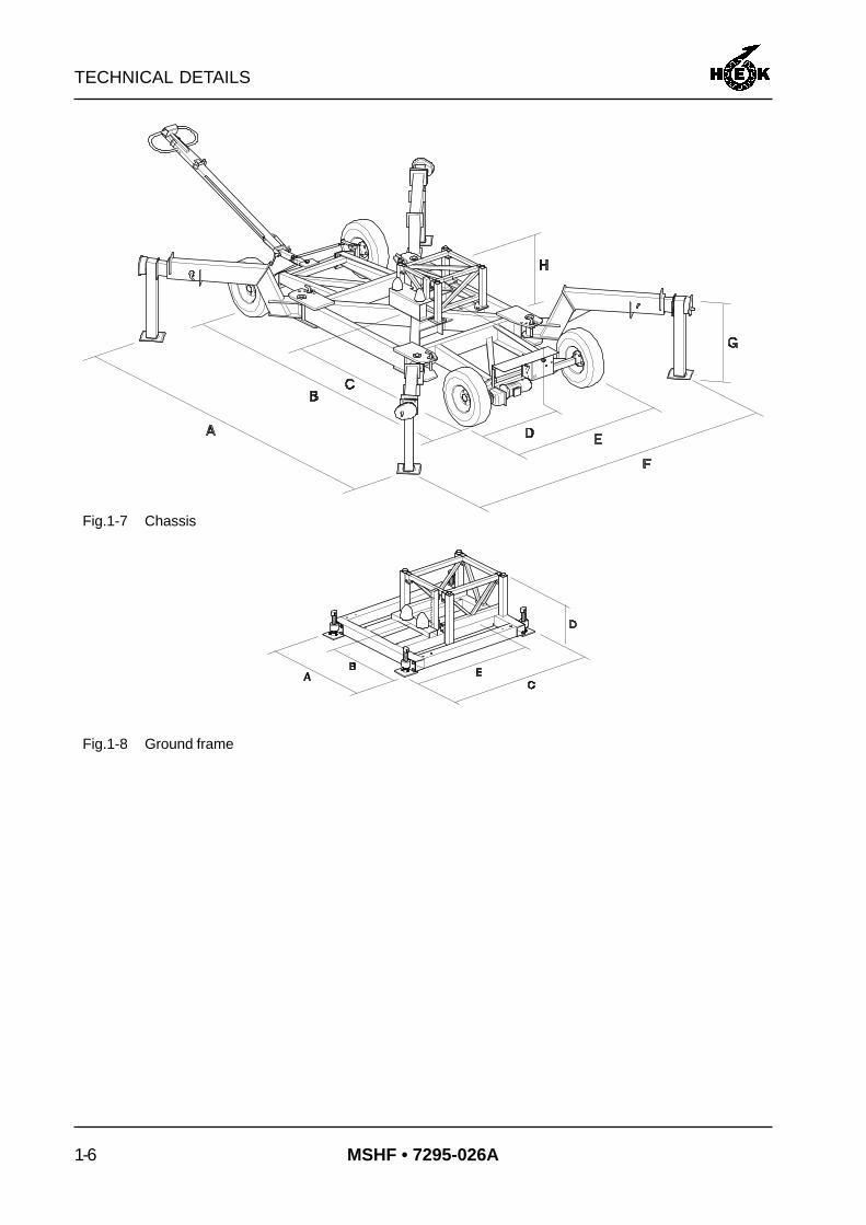
Fig.1-7 Chassis
Fig.1-8 Ground frame

TECHNICAL DETAILS
1-7MSHF • 7295-026A
1.4 Chassis
1.5 Ground frame
Dimension A 1200 mm 47.2 in
Dimension B 600 mm 23.3 in
Dimension C 1560 mm 61.4 in
Dimension D 500 - 600 mm 19.7 - 23.6 in
Dimension E 1100 mm 43.3 in
Weight 182 kg 400 lb
Height of the platfrom from theground
depending of lower strikerplate
depending of lower strikerplate
Dimension A 4520 - 6540 mm 175.9 - 257.5 in
Dimension B 4300 mm 167.3 in
Dimension C 2150 mm 83.7 in
Dimension D 1250 mm 48.6 in
Dimension E 1770 mm 69.7 in
Dimension F 1600 - 4590 mm 63.0 - 178.6 in
Dimension G 668 - 968 mm 26.0 - 37.7 in
Dimension H 775 - 848 mm 30.2 - 33.0 in
Weight 1750 kg 3850 lb
Number of motors 1 1
Rated power 0.75 kW 0.75 kW
Tyre pressure 5 bar 71.5 psi
Driving speed 2 km/h 1.25 mph
Height of the platform from theground
depending on lower strikerplate
depending on lower strikerplate

TECHNICAL DETAILS
1-8 MSHF • 7295-026A
1.6 Platform construction
1.6.1Symmetrical platformconstruction
Drive unit: 1.30 m / 4.26 ft = AElement 80: 0.80 m / 2.62 ft = BElement 150: 1.50 m / 4.92 ft = C
Twin mast machine
A-symmetrical configurations may be possible. This may only be done with prior writtenapproval of the supplier.
Single mast machine
Length platform
B A B 2.9 m 9.5 ft
C A C 4.3 m 14.1 ft
B C A C B 5.9 m 19.4 ft
C C A C C 7.3 m 24.0 ft
B C C A C C B 8.9 m 29.2 ft
C C C A C C C 10.3 m 33.8 ft
Mast distance* Centre panel between the masts Length platform
7.3 m 24.0 ft A C C C C A 8.5 m 27.9 ft
8.1 m 26.6 ft A C C C C B A 9.3 m 30.5 ft
8.8 m 28.9 ft A C C C C C A 10.0 m 32.8 ft
9.6 m 31.5 ft A C C C C C B A 10.8 m 35.4 ft
10.3 m 33.8 ft A C C C C C C A 11.5 m 37.7 ft
11.1 m 36.4 ft A C C C C C C B A 12.3 m 40.4 ft
11.8 m 38.7 ft A C C C C C C C A 13.0 m 42.7 ft
12.6 m 41.3 ft A C C C C C C C B A 13.8 m 45.3 ft
13.3 m 43.6 ft A C C C C C C C C A 14.5 m 47.6 ft

TECHNICAL DETAILS
1-9MSHF • 7295-026A
Side panels (2x) in case of a symmetrical installation.With multiple elements, the element of 1.5 m / 4.92 in (C) must be attached on the sideof the mast.
* The mast distance and thus the platform length can be enlarged (10cm / 3.94 in),by replacing one element 150 by two elements 80.
** These combinations are not allowed.
Mast distance* B C B + C C + C B + C + C C + C + C
24.0 ft 33.1 ft 37.7 ft 43.0 ft 47.2 ft ** **
26.6 ft 35.8 ft 40.4 ft 45.6 ft 50.2 ft ** **
28.9 ft 38.1 ft 42.7 ft 47.9 ft 52.8 ft 57.7 ft **
31.5 ft 40.7 ft 45.3 ft 50.5 ft 55.1 ft 60.4 ft 65.0 ft
33.8 ft 43.0 ft 47.2 ft 52.8 ft 57.4 ft 62.7 ft 67.3 ft
36.4 ft 45.6 ft 50.2 ft 55.4 ft 60.0 ft 65.3 ft 70.0 ft
38.7 ft 47.9 ft 52.5 ft 57.7 ft 62.3 ft 67.6 ft 72.5 ft
41.3 ft 50.5 ft 55.1 ft 60.4 ft 65.0 ft 70.2 ft 74.8 ft
43.6 ft 52.8 ft 57.4 ft 62.7 ft 67.3 ft 72.5 ft 77.1 ft
Mast distance * B C B + C C + C B + C + C C + C + C
7.3 m 10.1 m 11.5 m 13.1 m 14.4 m ** **
8.1 m 10.9 m 12.3 m 13.9 m 15.3 m ** **
8.8 m 11.6 m 13.0 m 14.6 m 16.1 m 17.6 m **
9.6 m 12.4 m 13.8 m 15.4 m 16.8 m 18.4 m 19.8 m
10.3 m 13.1 m 14.4 m 16.1 m 17.5 m 19.1 m 20.5 m
11.1 m 13.9 m 15.3 m 16.9 m 18.3 m 19.9 m 21.3 m
11.8 m 14.6 m 16.0 m 17.6 m 19.0 m 20.6 m 22.1 m
12.6 m 15.4 m 16.8 m 18.4 m 19.8 m 21.4 m 22.8 m
13.3 m 16.1 m 17.5 m 19.1 m 20.5 m 22.1 m 23.5 m

TECHNICAL DETAILS
1-10 MSHF • 7295-026A
1.7 Loading of the mast climbingwork platform
1.7.1Outriggers chassis
The outriggers of the chassis can be placed and locked in different positions. Themaximum free standing height of the mast climbing work platform is also depended onthe position of the outriggers.
Fig.1-9 Outrigger locking
Position of the locking pinPosition of the outriggers
1 2 3 4
Maximumfreestandingmast height
X -position front A A A A 20 m 65.6 ft
X -position back A A A A 20 m 65.6 ft
½K -position front A A B B 15 m 49.2 ft
½K -position back B B A A 15 m 49.2 ft
K -position front A A C C 7.5 m 24.6 ft
K -position back C C A A 7.5 m 24.6 ft

TECHNICAL DETAILS
1-11MSHF • 7295-026A
1.7.2 Single mast machine
The payload must be equaldistributed on the platform.
Drive unit: 1.30 m / 4.26 ft = AElement 80: 0.80 m / 2.62 ft = BElement 150: 1.50 m / 4.92 ft = C
The P numbers in the diagram are the EMOS program numbers. For adjusting the EMOSsystem see chapter 6.10.
Maximum payload single mast climbing work platform
* If the maximum height is limited to 17.5 m / 57.4 ft, the payload and the EMOSsetting of the anchored situation can be used.
Machine configurationMaximum loading capacity depending of situation inuse
Anchored Free standing
B A B 2300 kg 5060 lb P22 2300 kg 5060 lb P22
C A C 2200 kg 4840 lb P22 2200 kg 4840 lb P22
B C A C B 2000 kg 4400 lb P22 2000 kg 4400 lb P22
C C A C C 1800 kg 3960 lb P22 1800 kg 3960 lb P22
B C C A C C B 1600 kg 3520 lb P22 1000 kg* 2200 lb* P15*
C C C A C C C 1500 kg 3300 lb P22 750 kg* 1650 lb* P13*

TECHNICAL DETAILS
1-12 MSHF • 7295-026A
1.7.3Twin mast machine
The payload must be equaldistributed on the platform.
Drive unit: 1.30 m / 4.26 ft = AElement 80: 0.80 m / 2.62 ft = BElement 150: 1.50 m / 4.92 ft = C
The P numbers in the diagrams are the EMOS program numbers. For adjusting theEMOS system see chapter 6.10.
Maximum payload twin mast climbing work platform (free-standing or anchored).
Mast distance Centre panel between the masts Max. payload EMOS
7.3 m 24.0 ft A C C C C A 3500 kg 7700 lb P15
8.1 m 26.6 ft A C C C C B A 3500 kg 7700 lb P15
8.8 m 28.9 ft A C C C C C A 3500 kg 7700 lb P15
9.6 m 31.5 ft A C C C C C B A 3500 kg 7700 lb P16
10.3 m 33.8 ft A C C C C C C A 3500 kg 7700 lb P16
11.1 m 36.4 ft A C C C C C C B A 3000 kg 6600 lb P14
11.8 m 38.7 ft A C C C C C C C A 2700 kg 5940 lb P14
12.6 m 41.3 ft A C C C C C C C B A 2300 kg 5060 lb P12
13.3 m 43.6 ft A C C C C C C C C A 2000 kg 4400 lb P11

TECHNICAL DETAILS
1-13MSHF • 7295-026A
Maximum payload twin mast climbing work platform with side panels (free-standing oranchored).
* Maximum free standing height in X-position 15 meter.** These combinations are not allowed.
Platform elements on the side of the mast
Mastdistance
B C B + C C + C B + C + C * C + C + C *
24.0 ft 8800 lb / P19 8800 lb / P20 8360 lb / P20 7920 lb / P21 ** **
26.6 ft 8800 lb / P20 8580 lb / P20 8140 lb / P20 7700 lb / P20 ** **
28.9 ft 8800 lb / P21 8360 lb / P20 7920 lb / P20 7480 lb / P20 7040 lb / P20 **
31.5 ft 8580 lb / P21 8140 lb / P21 7700 lb / P21 7260 lb / P21 6820 lb / P21 6600 lb / P21
33.8 ft 8360 lb / P21 7920 lb / P21 7480 lb / P21 7260 lb / P21 6820 lb / P21 6380 lb / P21
36.4 ft 7700 lb / P20 7700 lb / P21 7260 lb / P21 7040 lb / P21 6600 lb / P21 6160 lb / P21
38.7 ft 6600 lb / P16 7260 lb / P19 7040 lb / P21 6820 lb / P21 6380 lb / P21 5940 lb / P20
41.3 ft 5720 lb / P15 6160 lb / P16 6600 lb / P19 6600 lb / P21 6160 lb / P21 5720 lb / P21
43.6 ft 4820 lb / P12 5280 lb / P15 5720 lb / P17 5940 lb / P19 5940 lb / P21 5500 lb / P20
Platform elements on the side of the mast
Mastdistance[m]
B C B + C C + C B + C + C * C + C + C *
7.3 4000 kg / P19 4000 kg / P20 3800 kg / P20 3600 kg / P21 ** **
8.1 4000 kg / P20 3900 kg / P20 3700 kg / P20 3500 kg / P20 ** **
8.8 4000 kg / P21 3800 kg / P20 3600 kg / P20 3400 kg / P20 3200 kg / P20 **
9.6 3900 kg / P21 3700 kg / P21 3500 kg / P21 3300 kg / P21 3100 kg / P21 3000 kg / P21
10.3 3800 kg / P21 3600 kg / P21 3400 kg / P21 3300 kg / P21 3100 kg / P21 2900 kg / P21
11.1 3400 kg / P20 3500 kg / P21 3300 kg / P21 3200 kg / P21 3000 kg / P21 2800 kg / P21
11.8 3000 kg / P16 3300 kg / P19 3200 kg / P21 3100 kg / P21 2900 kg / P21 2700 kg / P20
12.6 2600 kg / P15 2800 kg / P16 3000 kg / P19 3000 kg / P21 2800 kg / P21 2600 kg / P21
13.3 2200 kg / P12 2400 kg / P15 2600 kg / P17 2700 kg / P19 2700 kg / P21 2500 kg / P20

TECHNICAL DETAILS
1-14 MSHF • 7295-026A
1.8 Anchorforces
Torque scaffold coupling: 50 Nm / 37 lb ft.
With the calculation of the anchor forcesshow in the table the following demandsare considered: - Anchor distance: 13-15 m /
42.6 - 49.2 ft
- Maximum mastheight above last anchor:0.4 x anchor distance
- Loading during assembling:Single: max. 750 kg / 1650 lb+ 2 personsTwin: max. 1500 kg / 3300 lb+ 4 persons
- Maximum, windspeed duringassembling: 6 Beaufort (12,5 m/sec).(41 ft/sec)
- Distance a (mast centre to facade):0.9 -1.63 m / 35.4 - 64.2 in
- Distance b (between the anchor pointson the facade): min. 0.7 m / 27.6 in
- Ratio a/b: 0.8 - 2.0
The anchorforces of the MSHF up to 100 meters are given in the undermentioned table.
Above 100 meters the anchor forces will be 20 % higher than the anchor forces in thegiven table.
Fig.1-10 Anchor forces
Ratio a/b
0.8 1.0 1.2 1.4 1.6 1.8 2.0
5.9 kN 7.0 kN 8.3 kN 9.5 kN 10.7 kN 11.9 kN 13.0 kNAnchorforce F1
1327 lbf 1574 lbf 1865 lbf 2136 lbf 2406 lbf 2676 lbf 2923 lbf
4.2 kN 4.7 kN 5.3 kN 5.7 kN 5.9 kN 5.6 kN 6.0 kNAnchorforce F2
945 lbf 1057 lbf 1192 lbf 1281 lbf 1327 lbf 1259 lbf 1349 lbf

COMPONENTS
2-1MSHF • 7295-026A
2. COMPONENT DESCRIPTION
2.1 General description
The basic set of the mast climbing workplatform with rack and pinion drive consistsof the following 5 main parts:
* drive unit* mast* platform elements and fences* chassis or ground frame* control system
The drive unit moves along the mast withthe aid of Nylontron rollers.The motors are fitted with centrifugalbrakes which retard the platform if thespeed of descent is exceeded.
The drive unit, operated by 2 electricmotors, is moved along the mast by meansof a single pinion on each motor. For amast climbing work platform with twomasts, the motors are automaticallycontrolled to ensure parallel operation.
Much consideration has been given tosimple and safe assembly anddisassembly.
A crane on the platform (option) ensuresthat the mast elements can be positionedquickly and safely.
The platform can be adjusted to suit therequired working situation with the use ofseparate platform elements. The width ofthe platform can be adjusted by means ofoutriggers.
Fig.2-1 Basic set MSHF chassis/ground frame

COMPONENTS
2-2 MSHF • 7295-026A
All electrical connections, which must bedisconnected for transport purposes, canbe made by means of connectors.
The electrical installation is divided overthree boxes:
- The control box on the platform.- The connection box on the chassis (only
when a chassis is used)- The control box on the tow bar (only
when a chassis is used)
The simple construction ensures that only aminimum of maintenance is required.
The mast elements, the chassis, the driveunit, the cable guides and various othercomponents are protected from corrosionby an appropriate surface treatment.

SAFETY
3-1MSHF • 7295-026A
3. SAFETY
No changes or modificationsmay be made to the machine.
The ground surface must besufficiently stable to support theweight of the machine and themast.
The mast must ALWAYS beanchored in accordance with theinstructions
If during assembly anddisassembly, the fences do notprovide sufficient protection,suitable safety harness must beused at heights above 2 metres.
3.1 General
The machine is constructed to be safe,both during assembly and in use. Themachine is thus provided with the followingbuilt-in and additional safety features:- The motor brake works automatically if
the supply voltage fails.- If the TOP limit switch fails to operate,
so that the mast climbing work platformcontinues to rise, an additionalemergency TOP limit switch isoperated.
- If the LOWER limit switch fails tooperate, so that the mast climbing workplatform continues to descend, anadditional emergency LOWER limitswitch is operated.
- If the TOP limit switch fails and the redtopmast is not mounted, so that themast climbing work platform continuousto rise, the drive unit will rest on thesafety hooks.
- If the pinion runs out the rack the EMOSsystem will stop the drive unit by meansof differential current measurement.
3.2 Safety prior to use
- The chassis or ground frame must beeffectively supported.
- The working area around the machinemust be free from obstacles.
- The machine must be securelyanchored at the specified intervals.
3.3 Safety in use
In winds of strengths above6 Beaufort (12.5 m/s) (41.1 ft/s)by a freestanding machine or7 Beaufort (15.7 m/s) (51.5 ft/s)by an anchored machine, themachine must not be used andthe platform must be set in thelowest position.
There must be no obstructions inthe path of the machine.
During use, no person shouldstand under the machine.

SAFETY
3-2 MSHF • 7295-026A
Material must never extendbeyond the outer limits of theplatform. Items which may rollmust be properly secured.Materials must never be stackedagainst the fencing.
If work must be carried on closeto high voltage cables, aminimum safety distance of15 m / 50 ft must be maintained.
When materials and/or tools witha large surface area will be usedcontact your supplier inconnection with wind sensitivity.
- If the machine is to be used during thehours of darkness, the area must beadequately lit, so that the user has agood view in all conditions.
- In order to ensure that no personunintentionally walks under the platform,the mast climbing work platform must besurrounded with suitable fencing.
- The machine may only be used for thepurpose for which it was designed, thatis, the vertical transportation of personsand materials with a maximum weightwithin the design limits of the particularconstruction.
- Loads (materials, persons, etc.) mustbe distributed in accordance with theloading diagram.
- Operations on the mast climbing workplatform may only be carried out bypersons with adequate knowledge andqualifications to do so.
- Inspection and maintenance must becarried out as given in this instructionmanual.
- During assembly and maintenance, themast climbing work platform may not beused for other purposes.
- Keep hatches in the base of theplatform clear. From the platform it mustbe possible to get, to the emergencydescent controls via the hatches.
- The competence and sense ofresponsibility of the operator orengineer are essential to the efficientuse of the platform.
- Local safety laws and regulations mustalways be followed.
- Technical personnel must be in aposition to deal with any difficultyencountered in every possible situationduring assembly and disassembly. Theoperating personnel must be familiarwith those situations which can occurduring use.
- If operating or technical personnel reporterrors or dangers or are not aware ofthe safety regulations, the owner or theperson responsible must be informedimmediately.
- For machines with two masts, theremust always be two persons present onthe platform during use. This in case theneed to make an emergency descent.
- The working area must be kept freefrom obstacles (building materials, dirt,snow, etc.).
- Fences must never removed duringnormal use.
- The platform must only be entered and/or loaded when it is in its lowestposition. The same rule applies toleaving the platform.
- When electrical storms are expected,work on the platform must be stopped intime to avoid the danger of lighteningstrikes. The power supply must beswitched off and the connectorwithdrawn from the supply socket.

SAFETY
3-3MSHF • 7295-026A
- Platform extensions on telescopicsupports may only be used to carrypersonnel. Such personnel may onlystand on these extensions when themachine is stationary.
- If erecting two adjacent platforms theremust be a clear gap between the endsof the platforms of at least 0.5 meter /19.7 inch.
3.4 Safety after use
- Transport on public roads must only bedone with a truck intended for thepurpose.
- The platform must be placed in thelowest position and the main switchmust be secured.
3.5 Built-in and additional safetyfeatures
The MSHF mast climbing work platform isprovided with the following in-built andadditional safety features:
- Phase control relay in the control box.- "Emergency stop" push button on every
control box.- Electrical access protection.- Hooks on the drive unit. The platform
remains secured on these should all thelimit switches fail and should the redmast top section also be missing.
- Autolevel for machines with two masts.Locks the platform if one side dropsmore than the other during anemergency descent.
- In the event of a power failure the motorbrakes are operated automatically toprevent the platform descendingunexpectedly.
- Centrifugal brakes ensure a controlleddescent in the event of an emergency.
- The single mast construction has aneccentric overload safety device. Thislocks the platform if the platform isoverloaded on one side.
- The Emos system locks the platform ifone of the motors fails.
- In the event of a power failure it ispossible for the platform to make anemergency descent by manuallyreleasing the motor brakes.
- Audio Visual Warning. During descentof the platform, a buzzer will sound anda light will flash underneath the platform.
- The mast climbing work platform canonly be moved on the chassis when theplatform is in the lowest position.

SAFETY
3-4 MSHF • 7295-026A

TRANSPORT
4-1MSHF • 7295-026A
4. TRANSPORT
Transportation on the chassisover the public roads is notpermitted.
The national valid trafficregulations must be observed.
Because of its limited dimensions, thebasic implementation of the machine canbe transported with a normal lorry. Ensurethat, during transport, all securing devicesare properly fitted and that the machine islowered onto the buffers.
Disassemble the machine beforetransporting it as described in chapter 8.
For the transport dimensions, seechapter 1.
For transport, all fences, steps and mastprotection must be removed.
For transportation, secure the machinecarefully onto the loading platform of thetransport vehicle.
The machine can be loaded and unloadedfrom the transport vehicle using a cranemounted on the vehicle, a crane on thebuilding site or a fork-lift truck. See figure4-1 for loading and unloading points.Set the machine down carefully to avoiddamage.
See figure 4-1A Lifting point, for drive unit only!B Support points for the fork of a fork-lift
truck.
Fig.4-1 Transport MSHF

TRANSPORT
4-2 MSHF • 7295-026A
4.1 Repositioning on the building site
Ensure that trees, power cablesetc., cannot be touched.
During movement there may beno load on the platform.
Once on the building site, the mastclimbing work platform can be moved inthe lowest position on its chassis.
On a hard flat horizontal surface and whenthere is no wind, the mast may have amaximum height of 20 m / 65.6 ft duringrepositioning. The platform must be on thebuffers. The legs must be set out in an Xposition and secured. The jack must bescrewed out until they just are clear theground.
When the circumstances are unfavourablethan the above mentioned circumstances,contact your supplier.
A machine with two masts may only berepositioned on its chassis if no curvesmust be negotiated. If a curve must befollowed, the machine must first be splitinto two single-mast machines. Take themaximum platform length of a single mastmachine into account.
If there is no electrical power supplyavailable, the chassis can be moved byhand or behind a vehicle. The hand brakelever on the chassis motor must then beused.
The maximum speed at which the chassismay be towed behind a vehicle is 30 m/min / 98.4 ft/min. Exceeding this speed cancause serious damage to the motor.
Fig.4-2 Locking pin outrigger chassis
Fig.4-3 Brake lever chassis

TRANSPORT
4-3MSHF • 7295-026A
4.2 Chassis drive unit
Moving the machine on itschassis over public roads is notpermitted.
During movement there may beno load on the platform.
1. Place the platform in the lowestposition.
2. Check that the tow bar is secured.
3. Insert the connector from the platformin the socket on the switch box of thechassis.
4. Connect the control cable from thetow bar to the chassis.
5. The chassis can be repositioned bypushing the knob (arrow) of therequired direction. The controlvoltage can always be switched off bypushing the emergency push-button.
After the chassis has been repositioned,the red push-button must be pressed andthe connectors for the power supply andcontrols withdrawn.
Fig.4-4 Switch box chassis
Fig.4-5 Control box chassis

TRANSPORT
4-4 MSHF • 7295-026A
No. of drive units x 950 kg / 2090 lb =No. of chassis x 1750 kg / 3850 lb =No. of ground frames x 182 kg / 400 lb =No. of platform elements 80 x 90 kg / 198 lb =No. of platform elements 150 x 140 kg / 308 lb =No. of mast elements 125 x 80 kg / 176 lb =No. of mast elements 150 x 103 kg / 227 lb =No. of plug-in fences 80 x 12 kg / 26 lb =No. of plug-in fences 150 x 18 kg / 40 lb =No. of head fences x 30 kg / 66 lb =No. of corner posts x 6,5 kg / 14 lb =
Total transport weight = kg / lb+
4.3 Repositioning with a crane
During movement there may beno load on the platform.
At the building site the mast climbingwork platform can be repositioned with acrane under the following circumstances.
A maximum of 9 mast elements may bemounted on the chassis or the groundframe. The eye hook of the crane can beattached to the mast with lifting slings.
The total transport weight can becalculated on the undermentioned way.

CONTROL COMPONENTS
5-1MSHF • 7295-026A
5. CONTROL COMPONENTS
5.1 Power supply socket for the driveunit
The power supply cable for the electricalsupply between the building siteconnection and the mast climbing workplatform must be connected to the socket.See chapter 1 for the cable specifications.
5.2 Power supply socket for thechassis
The power supply cable for the electricalsupply between the building siteconnection and the chassis must beconnected to the socket.
Fig.5-1 Power supply socket drive unit
Fig.5-2 Power supply socket chassis

CONTROL COMPONENTS
5-2 MSHF • 7295-026A
5.3 Platform control box
The door of the control box is secured withtwo quick-release fastener.The control box is provided with thefollowing push buttons:
1. Main switch.2. Info panel.3. Config panel.4. Signal light.5. Adjustment switch EMOS.6. Push button UP.7. Blue control light.8. Push button DOWN.9. Emergency push-button.10. Keyswitch buffer.11. Horn.12. Keyswitch adjustment left/right.
When the Emergency push-button ispressed it is locked in the depressedposition. It can be unlocked by rotating it.
The main switch can be secured with apadlock to prevent unauthorized use of theplatform.
The following components are mounted inthe control box:-the main switch-the safety relay-the control relay-the transformer-the automatic fuses
Fig.5-3 Control box

ASSEMBLY AND ANCHORING
6-1MSHF • 7295-026A
6. ASSEMBLY AND ANCHORING
Definition left and right in relation to positioning:
Left-hand: Viewed from the step side, the machine is fitted to the left-hand side.Right-hand: Viewed from the step side, the machine is fitted to the right-hand side.
Fig.6-1 Position machine
If assembly work must be interrupted, this must be done in such a way that, when the workis restarted it is clear what stage had been reached when work was stopped. For thisreason always complete a part of the assembly, for example, assemble collect or secure allthe components for a connection, complete a ground support or completely assemble ananchor before stopping work.
While the mast is being erected, no more than two persons with a single mast machine orfour persons with a twin mast machine, may be on the platform, so that no more than 75%of the lifting capacity is used.The assembly must always be followed by a test run, as described in section 7.3. Until thetest has been performed, the platform may not be used for any purpose other thantransporting its own mast elements and anchoring components.
The loading of the mast climbing work platform must be planned so that when, in theassembly situation, the maximum height of the mast above the last anchor is reached (themaximum distance between anchors), the material load on the platform is a minimum.

ASSEMBLY AND ANCHORING
6-2 MSHF • 7295-026A
6.1 Preparation for assembly
Ensure that the site where themast climbing work platform willbe assembled accords with thenational requirements and thatpermission has been obtainedfrom the relevant authorities forthe assembly.
- Ensure that a suitable power supply,good lighting, lifting equipment and toolsare available.
- Ensure that the building site is easilyaccessible to the vehicle which willdeliver the mast climbing work platform.
- Prepare the site with suitable supportand anchoring facilities.
- Ensure that the position where the mastclimbing work platform will stand hasgood drainage.
- Plan the positioning of the mastclimbing work platform so that where themast needs to be anchored, it can be soanchored with the standard material.
- The components of the mast climbingwork platform mast should be placed asclose as possible to the place where itwill be assembled.
- The electrical power supply connectionmust be placed as close to the mastclimbing work platform as possible soas to reduce the voltage drop to aminimum. If the voltage reduction is toogreat the machine may not functioncorrectly.

ASSEMBLY AND ANCHORING
6-3MSHF • 7295-026A
6.2 Ground support
Before the position for the mastclimbing work platform is prepared acheck must be made to ensure thatthe distance between the mast andthe working surface can be spannedby the standard anchoring material.
1. Ensure that the forces are spreadover as large an area as possible.
2. The soil must be able to withstand aground pressure of at least2 kg/cm² / 30 lb/in². If this requirementis not met, soil improvement must becarried out such that the groundsatisfies this minimum requirement.
3. The ground support must be flat andcentrally loaded with a minimumground support of 400x400 mm /15.7 x 15.7 in.
When a chassis is used, a ground supportmust be placed under the jack close to themast and under the jack of the 4 extendinglegs. The frame must have a supportplaced under the mast and under the 4corners (not under the jacks).
4. The ground support must be durableand of such a quality that the load canbe transferred without plasticdeformation.
5. If the machine is installed on aconcrete foundation or on a hardroad surface, the installation must beprovided with wooden packing toprevent slipping.
Fig.6-2 Ground support chassis
Fig.6-3 Ground support ground frame

ASSEMBLY AND ANCHORING
6-4 MSHF • 7295-026A
6.3 Positioning the mast climbingwork platform
A fence (height 1.10 m / 43.3 in)completely surrounding theplatform is compulsory. If thedistance between the platformand the facade is 0.3 m - 0.5 m /11.8 in - 19.7 in a fence with aheight of 0.7 m / 27.6 in can beused. If the distance between theplatform and the facade is lessthan 0.3 m / 11.8 in a fence is notcompulsory but in this case akick board with an height of0,15m / 5.9 in must be fitted.
Wheels of the chassis should nothave a bearing function whileassembly and operating theplatform.
Distance to the facade with standardanchoring.A = 575 - 1300 mm / 22.6 - 51.2 inB = 550 - 1275 mm / 21.7 - 50.2 inC = 25 mm / 1 in
There are four ways in which the mastclimbing work platform can be placed:
- single mast, freestanding (chassismounted)
- single mast, anchored (chassis orground frame mounted)
- two masts, freestanding (chassismounted)
- two masts, anchored (chassis or groundframe mounted).
Fig.6-4 Distance to the facade

ASSEMBLY AND ANCHORING
6-5MSHF • 7295-026A
6.3.1 Mast climbing work platform withsingle mast on a chassis
1. Position the chassis parallel to thewall.
2. Withdraw the outriggers on the stepside and secure them. Withdraw theoutriggers on the side nearest thewall as far as possible. The maximumheight for a freestanding machinedepends on the position of theoutriggers and the loading (seeloading diagram, chapter 1.5).
3. Place the ground supports.
4. Unscrew the jack until the wheels nolonger contact the ground and adjustthe machine to be level. Themeasurement must be done with aspirit level with a minimum length of 1meter / 40 inch.
5. Check that the locking pin forsecuring the autolevel device and thelower striker plate are mounted.
6. Assemble the platform componentssequentially on both sides until thedesired length is attained. Theplatform may not exceed themaximum length.
7. Tighten the platform bolts until thespecified torque is applied.
8. The width of the platform can beadjusted to fit the form of the façade.See section 6.6.
Fig.6-5 Locking pin outrigger chassis
Fig.6-6 Autolevel locking pin
Fig.6-7 Lower striker plate

ASSEMBLY AND ANCHORING
6-6 MSHF • 7295-026A
9. Mount the steps and secure themwith locking pins.
10. Mount the fencing and secure it with"hairpins".
11. Mount the gate and the cam for thegate safety switch. The roller must fallinto the cam when the gate is closed
6.3.2 Mast climbing work platform withone mast on a ground frame
1. Position the ground frame parallel tothe wall.
2. Place the ground supports.
3. Level the machine using the jacks.Ensure that the mast is vertical inboth directions by checking with aspirit level (with a length of at least 1metre / 40 inch) placed against twoadjacent sides of the mast. Placewooden packing under the machineto provide optimum load spreadingand stability.
Fig.6-9 Step
Fig.6-10 Fence
Fig.6-11 Gate safety switchFig.6-8 Lower striker plate

ASSEMBLY AND ANCHORING
6-7MSHF • 7295-026A
4. Check that the locking pin forsecuring the autolevel and the lowerstriker plate are mounted.
5. Assemble the platform componentssequentially on both sides until thedesired length is attained. Theplatform may not exceed themaximum length.
6. Tighten the platform bolts until thespecified torque is applied.
7. The width of the platform can beadjusted to fit the form of the façade.See section 6.6.
8. Mount the steps and secure themwith locking pins.
9. Mount the fencing and secure it with"hairpins".
10. Mount the gate and the cam for thegate safety switch. The roller must fallinto the cam when the gate is closed.
Fig.6-12 Step
Fig.6-14 Fence
Fig.6-15 Gate safety switch
Fig.6-13 Autolevel locking pin

ASSEMBLY AND ANCHORING
6-8 MSHF • 7295-026A
6.3.3 Mast climbing work platform withtwo masts on a chassis
One drive unit must be adjustedfor "left" and the other for "right".
1. Check that the left-hand machine isadjusted for "left" and the right-handmachine for "right". See section 6.7.
2. Position the chassis parallel to thewall and with a separation to allow forthe required distance between themasts + 1 metre / 3.3 ft.
3. Withdraw the outriggers on the stepside completely and secure them.The outriggers on the side facing thewall should be withdrawn as far aspossible.The maximum freestanding heightdepends on the position of thetelescopic arms and the loading (Seeloading diagram, chapter 1.5).
4. Place the ground supports for thischassis.
5. Unscrew the jack for this chassis untilthe wheels no longer touch theground and level the machine. Themeasurement must be done with aspirit level with a minimum length of 1meter / 40 inch.
6. Check that the autolevel locking pinsand the lower striker plates aremounted on both chassis.
Fig.6-18 Lower striker plate
Fig.6-17 Autolevel locking pin
Fig.6-16 Locking pin outrigger chassis

ASSEMBLY AND ANCHORING
6-9MSHF • 7295-026A
7. Assemble the platform components,by both chassis simultaneously onboth sides of the drive units until thedesired length is attained. Theplatforms may not exceed themaximum length.
8. Tighten the platform bolts until thespecified torque is applied.
9. Push the second chassis towards thefirst and fix the platform elementstogether.
10. Repeat steps 3 to 5 for the secondchassis.
11. The width of the platform can beadjusted to fit the form of the façade.See section 6.6.
12. Mount the steps and secure themwith locking pins.
13. Mount the fencing and secure it with"hairpins".
Fig.6-20 Fence
Fig.6-19 Step

ASSEMBLY AND ANCHORING
6-10 MSHF • 7295-026A
14. Mount the gate and the cam for thegate safety switch. The roller must fallinto the cam when the gate is closed
15. Remove the autolevel locking pinsfrom both machines.
16. Remove the dummy plugs from thecontrol cable sockets.
17. Connect the control cable and theelectrical power supply cable. Securethe cables to the underside of theplatform neatly so that they do nothang down.
Fig.6-21 Gate safety switch
Fig.6-22 Autolevel locking pin
Fig.6-23 Control cable dummy plug

ASSEMBLY AND ANCHORING
6-11MSHF • 7295-026A
6.3.4 Mast climbing work platform withtwo masts on ground frames
One drive unit must be adjustedfor "left" and the other for "right".
1. Check that the left-hand machine isadjusted for "left" and the right-handmachine for "right". See section 6.7.
2. Position the ground frames parallel tothe wall and with a separation toallow for the required distancebetween the masts.
3. Place the ground supports for bothground frames.
4. Level the machine using the jacks.Ensure that the mast is vertical inboth directions by checking with aspirit level (with a length of at least 1metre / 40 inch) placed against twoadjacent sides of the mast. Placewooden packing under the machineto provide optimum load spreadingand stability.
5. Check that the autolevel locking pinsfor securing the parallel movementand the lower striker plates aremounted.
6. Assemble the platform componentssequentially on both sides of the driveunits until the desired length isattained. The platform may notexceed the maximum length.
7. Tighten the platform bolts until thespecified torque is applied.
8. Assemble the second ground frameto the first by fixing the platformelements together.
Fig.6-24 Autolevel locking pin
Fig.6-25 Lower striker plate

ASSEMBLY AND ANCHORING
6-12 MSHF • 7295-026A
9. The width of the platform can beadjusted to fit the form of the façade.See section 6.6.
10. Mount the steps and secure themwith locking pins.
11. Mount the fencing and secure it with"hairpins".
12. Mount the gate and the cam for thegate safety switch. The roller must fallinto the cam when the gate is closed.
Fig.6-26 Gate safety switch
Fig.6-27 Step
Fig.6-28 Fence

ASSEMBLY AND ANCHORING
6-13MSHF • 7295-026A
13. Remove the autolevel locking pinsfrom both machines.
14. Remove the dummy connecting plugsfrom the control cable sockets.
15. Connect the control cable and theelectrical power supply cable. Securethe cables to the underside of theplatform neatly so that they do nothang down.
Fig.6-29 Autolevel locking pin
Fig.6-30 Control cable dummy plug

ASSEMBLY AND ANCHORING
6-14 MSHF • 7295-026A
6.4 Assembly of the mast
If work has to be stopped, alwayscomplete the phase beingworked on. Tighten all the boltsused for the last attachment andswitch off and secure the mainswitch so that the machinecannot be operated.
As the assembly proceeds,place the anchor tubes, anchorsand cable guides as describedin section 6.5
Note that the power supplyconsists of3 x 400 V + neutral + safetyearth.
The mast(s) must always beassembled vertically.
In winds of strengths above6 Beaufort (12,5 m/s) (41 ft/s) themachine may not be assembled.
1. Connect the power supply to themachine.
2. Set the main switch in position I or II(the position depends on thedirection of phase rotation of thepower supply). If the display showscode 02 and the phaselight on thephaseguard relay does not burn, setthe main switch in the other position.The display must show code 00 andthe phase light will be burning.
Fig.6-31 Power supply
Fig.6-32 Main switch

ASSEMBLY AND ANCHORING
6-15MSHF • 7295-026A
3. When the mast climbing workplatform is delivered it is in the buffer.In order to remove the mobile workplatform out of the buffer, carry out thefollowing procedure:
1 Press the push-button "resetpositioning" and keep it pushed in.
2 Press the push-button "UP".
For a two-mast construction, checkthat the lower striker plates and theautolevel switches are properlyadjusted. See sections 6.8 and 6.9.
4. The mast climbing work platform israised and lowered by pressing theUP and DOWN push buttons. Whenthe push-button is released, the mastclimbing work platform stops. Inaddition, an emergency stop push-button is provided. When this buttonis pushed, the power of the motorswill be shut off.
5. Check that the proximity switch ismounted on both drive units.
6. Use a fork-lift truck or crane to raisethe mast elements onto the platform.Ensure that the maximum loadingpermitted during assembly is notexceeded.
7. Stand on the platform and use thecrane to place a mast element on thelast element assembled. Secure themast element with four bolts, washersand nuts. Tighten the bolts to thespecified torque value.(See chapter 1)
Fig.6-34 Proximity switch
Fig.6-33 Control buttons

ASSEMBLY AND ANCHORING
6-16 MSHF • 7295-026A
8. Raise the platform towards the top ofthe mast element and repeat theprocedure until another element mustbe assembled. Plan the procedureso that, when an anchor must befitted, the loading of material andmast elements is a minimum.
9. Ensure that anchors are placed at thespecified intervals.
10. Repeat this working method until themast has reached the requiredheight. The last element assembledmust always be the red top element.The maximum specified height mustnot be exceeded.
11. If a crane is available on the buildingsite, the mast can be more quicklyassembled. Up to five mast elementscan be assembled on the ground andthen raised into position with thecrane.
12. The mast must not extend too farabove the uppermost anchor (Seechapter 1). To achieve good stability,it is always better to place an anchoras close to the top of the mast aspossible.
13. Assemble the mast cover panelsfrom the platform and secure them.
14. The assembly is now complete. Theassembly must now be tested asdescribed in section 7.1
Fig.6-35 Red top mast element
Fig.6-36 Mast cover

ASSEMBLY AND ANCHORING
6-17MSHF • 7295-026A
6.5 Anchoring the mast
If work must be stopped, alwayscomplete the current phasebefore stopping. Tighten all thebolts for the latest fixture andsecure the main switch so thatthe mast climbing work platformcannot be operated.
Before starting to fix anyanchors, ensure that the chassis/ground frame is level.
The wall must be of such aquality that it can accept theforces applied to it via theanchors.
The platform extensions and theanchors must not come intocontact during raising andlowering.
The anchor forces must beapproved by the owner or theperson responsible for thebuilding to which the machine willbe anchored.
1. Check that the mast is vertical with aspirit level at least 1 metre / 40 inchlong. Recheck as each anchor issecured.
2. The mast must be anchored to thebuilding at the distances specified inthe table in chapter 1.
3. The anchors are assembled frommast adapters, horizontal anchortubes and a support tube.

ASSEMBLY AND ANCHORING
6-18 MSHF • 7295-026A
4. The horizontal anchor tubes and thesupport tubes can be supplied invarious lengths.
5. Fixing the anchors:- Anchoring is carried out using bolt
couplings, nut and bolt fasteningsand washers. If conditions make itnecessary, use may be made ofother approved attachmentmaterials which are suitable for theforces present. (Consult yourdealer).
- Cemented-in anchors must beallowed to become fully secure(the cement must have time toharden) before the mast climbingwork platform is assembled. Thecement or concrete used must bein accord with the specifications.
- If chemical anchors or expansionbolts are used, these must beapproved and must be able towithstand the forces involved.
- Specifications for these types ofbolts are available from thesupplier. Permission to use themmust be obtained from the localauthorities.

ASSEMBLY AND ANCHORING
6-19MSHF • 7295-026A
6. Securing the anchors:- Secure the mast adapters (1) to
the mast.- Fix the wall plates (2) to the
building.- Secure the horizontal anchor tubes
(3) between the mast adaptersand the wall plates.
- Tighten the horizontal anchor tubecouplings to the correct torquevalue.
- Use the adjustment construction toset the mast vertical and parallel tothe building.
- Fix the support tube (4).
6.6 Adjusting the platform width
The width of the platform can be adjustedto the shape of the building. As standardan extension of 1 metre / 3.3 ft is possible.In case work must carry out behind themast a anchor ramp must be mounted.
The planks used for adjusting theplatform must in every case besecured in every direction.
The platform widening and themast anchors must not come intocontact when the platform israised and lowered.
Fig.6-37 Anchoring

ASSEMBLY AND ANCHORING
6-20 MSHF • 7295-026A
A fence (height 1.10 m / 43.3 in)completely surrounding theplatform is compulsory. If thedistance between the platformand the facade is 0.3 m - 0.5 m /11.8 in - 19.7 in a fence with aheight of 0.7 m / 27.6 in can beused. If the distance between theplatform and the facade is lessthan 0.3 m / 11.8 in a fence is notcompulsory but in this case akick board with an height of0,15m / 5.9 in must be fitted.
The platform extension must be inaccordance with specification prEN1495.The platform extension must be fabricatedfrom a non-slip, easily cleaned material.The extension must be self draining. Thewidth of any openings or gaps in the floormust be sufficiently narrow that a ball with adiameter of 15mm will not pass through.The platform extension must be able towithstand a static load of 200kg / 440 lb onan square area of 0.1x0.1m / 0.4 x 0.4 inchon the least favourable part of the floorsurface without causing any permanentdistortion.
1. Pull out the outriggers and securethem with locking pins.
2. Cover the outriggers with planks.
3. Fix cross strips with a right-angleprofile to the underside of theplanking and secure them to theoutriggers.
4. Mount the anchor ramp to theoutriggers.
Fig.6-39 Anchor ramp
Fig.6-38 Outrigger platform extension

ASSEMBLY AND ANCHORING
6-21MSHF • 7295-026A
Fig.6-40 Machine setting left
Fig.6-41 machine setting right
Fig.6-42 switch left/right setting
6.7 Setting the machine left or right
The factory setting is stated on the typeplate fixed to the control box. An "R" in themachine number indicates right and an"L" indicated left.
The setting can be adjusted in thefollowing way.
1. Insert the operating bar of theparallel movement mechanism inthe required slot (left or right).
2. Set the switch on the control box inthe required position (left or right).

ASSEMBLY AND ANCHORING
6-22 MSHF • 7295-026A
Fig.6-43 Adjusting lower striker plate
6.8 Checking and adjusting the lowerstriker plates
For a two-mast construction, the strikerplates must be checked and if necessary,adjusted.
1. Lower the highest placed unit until thelimit switch just touches the lowerstriker plates.
2. Use the other unit to level theplatform.
3. Check that the limit switch justtouches the lower striker plate for thisunit.
4. If the lower striker plate does nottouch the limit switch, adjust theposition of the striker plate until it justtouches the limit switch.
5. Check the adjustment.

ASSEMBLY AND ANCHORING
6-23MSHF • 7295-026A
Fig.6-44 Brake lever drive unit
Fig.6-45 Autolevel switches
6.9 Checking the autolevel switches
For a twin mast construction, the autolevelswitches must be checked and adjusted ifnecessary.
1. Raise the platform by 3 metres /9.8 ft and level the platform by meansof the brake lever.
2. Operate the brake release on onedrive unit and, depending on thedistance between the centres of themasts, allow the unit to descend.Distance between centres 730 cm /24 ft : 25,5 cm / 10.0 in lower.Distance between centres 1330 cm /43.6 ft: 46 cm / 18.1 in lower.These distances represent a platformslope of 2 degrees.
3. Operate the "UP" push-button on theplatform. The lowest unit must now bethe first to rise.
4. Repeat the previous steps for theother unit.
5. If necessary, adjust the switches.

ASSEMBLY AND ANCHORING
6-24 MSHF • 7295-026A
Fig.6-47 Lightning protection
6.10 Adjusting the EMOS system
1. The switch can only been turned withthe correct key. Set the EMOS switch(1,2,3) in position 2. The config panelstarts to flash.
2. The program can be changed withthe UP or DOWN button on thecontrol box.
3. Set the desired program(See table chapter 1.7).
4. Set the EMOS switch on position 1.
5. The config panel shows the adjustedvalue.
6. Remove the key.
6.11 Lightning protection
1. Fasten the connecting cable betweenthe chassis/ground frame and themast.Cable specifications:- Insulated copper, 16 mm² cross
section.
2. Mount the connection between thechassis/ground frame and the earth.This connection must satisfy thefollowing specification:DIN VDE 0185, part II, §5.2The cable supplied (25 mm² / 0.0039in² cross section, 25 m / 82 ft long)must be connected to the terminalbox on the building site.
Fig.6-46 Adjusting EMOS

OPERATION
7-1MSHF • 7295-026A
7. OPERATION
7.1 General
No person may stand under themachine while it is in use.
Material may never extendbeyond the edges of theplatform. Items which can rollmust be properly secured. Theload may never be supportedagainst the fencing.
The maximum reaction force (forinstance caused by tools) of theplatform with regard to thefacade amounts for a singlemast machine 500 N / 113 lbfand for a twin mast machine 800N / 180 lbf.
When work stops for any reason,the main switch must be securedwith the padlock.
During rising or descending noperson may stand on theplatform extensions.
7.2 Preparation
1. Before the mast climbing workplatform is used it must be visuallyinspected (daily if it is used everyday) for:- anchors and cable guides- presence of all security devices- connection between mast
elements- position of the masts- any loose components
OPERATION
7-2 MSHF • 7295-026A
- ground supports and the quality ofthe ground
- electrical connections- protective covers (presence and
securing)- securing of the platform extension- operation of the limit switches- no obstacles in the path of the
platform- oil leaking from the drive units and
chassis motor- functioning of the motor brakes
(section 7.4).
2. Connect the electrical power supply.
3. Close the gates.
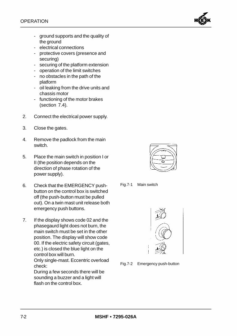
4. Remove the padlock from the mainswitch.
5. Place the main switch in position I orII (the position depends on thedirection of phase rotation of thepower supply).
6. Check that the EMERGENCY push-button on the control box is switchedoff (the push-button must be pulledout). On a twin mast unit release bothemergency push buttons.
7. If the display shows code 02 and thephasegaurd light does not burn, themain switch must be set in the otherposition. The display will show code00. If the electric safety circuit (gates,etc.) is closed the blue light on thecontrol box will burn.Only single-mast. Eccentric overloadcheck:During a few seconds there will besounding a buzzer and a light willflash on the control box.
Fig.7-1 Main switch
Fig.7-2 Emergency push-button

OPERATION
7-3MSHF • 7295-026A
8. If a two-mast construction is usedwith two different types of Controlboxes (one with a display and onewithout), the ON push-button must bepressed each time the platform israised or lowered. If the platform mustbe controlled by the control boxwithout a display.
7.3 Testing
1. Test the platform and check thefollowing:- all limit switches, striker plates and
safety devices and ensure thateverything is properly adjusted.
- that the path of the platform is notobstructed.
- the functioning of all the pushbuttons on the control box.
- the free movement of the powersupply cable.
Also test the platform brakes. (seesection 7.4)
7.4 Brake test
The brake test must be carried out daily.
1. Release the brake on one of themotors by pulling the lever on themotor. The platform may notdescend. Release the brake lever.
2. Release the other brake. Theplatform should not descend.Release the brake lever.
Fig.7-3 Brake lever drive unit

OPERATION
7-4 MSHF • 7295-026A
3. Repeat the previous two steps for theother drive unit.
If the platform descends, themast climbing work platformmust not be used. Consult theservice engineer.
7.5 Operation from the platform
UP: If this push-button ispressed, the platform israised. When thepush-button is released,the platform stopsimmediately.
DOWN: If this push-button ispressed, the platform islowered. When thepush-button is released,the platform stopsimmediately.
EMERGENCY: When this push-button ispressed, the platform islocked.
7.6 Operation in an emergencysituation
In an emergency, for example in the eventof a power failure, the platform can alwaysbe lowered.- Using the malfunction analysis in
chapter 10, try to solve the problem. Ifthe problem can not be solved it ispossible to make a emergency descentin the following way.
Fig.7-4 Push-buttons control box

OPERATION
7-5MSHF • 7295-026A
1. Open the trap door in the platform.
2. Remove the toolbox.
3. The motors have a lever whichpermits the brake to be released.
4. When this lever is operated, theplatform will begin to descend. For atwo-mast construction, the brakesmust be released by two personssimultaneously so a clear systemmust exist between them.
The speed of descent will be limitedby the centrifugal brake.
After a maximum descent of 5metres / 16.4 ft, stop the platformfor 2 minutes in order to avoidthe centrifugal brakes becomingoverheated, which will result intheir working less efficiently.
5. For a two-mast construction, take theopportunity during the stop situationthe set the platform level with the aidof the brake release mechanisms. Ifthe platform becomes excessivelyinclined, the autolevel safety systemwill come into operation. In this event,external help will be required.
Fig.7-5 Drive unit brake release

OPERATION
7-6 MSHF • 7295-026A
7.7 Eccentric overload device
The MSHF mast climbing work platform isprovided with an eccentric overloaddevice. The eccentric overload device isonly active in a single-mast construction.
When the platform is eccentric overloadedto 90%, the light on top of the control boxstarts to burn.
When the platform is eccentric overloadedto 100%, the light on top of the control boxwill burn and a buzzer will sound. In thissituation the machine can not be operated.
When the cause of overload is removedthe eccentric overload device will be resetautomatically.
Fig.7-6 Signal light

DISASSEMBLY AND TRANSPORT
8-1MSHF • 7295-026A
8. DISASSEMBLY AND TRANSPORT
Ensure that the maximumloading allowed during assemblyis not exceeded.
In winds of strenghts above6 Beaufort (12,5 m/s) (41 ft/s),the machine may not bedisassembled.
1. Remove the mast guards.
2. Disassemble the mast elementsabove the uppermost anchor. Beforeloosening the uppermost anchor,lower the disassembled elements tothe ground. Now disconnect theuppermost anchor.
3. Together with the disassembly of themast, the anchor tubes, the anchorsand the cable guides must bedisassembled.
4. If a crane is available on the buildingsite, the mast can be more quicklydisassembled. As many as five mastelements can be removed togetherand lowered to the ground with thecrane. The mast elements can furtherdisassembled on the ground.
5. Repeat this procedure until the mast,with the platform in its lowestposition, has been completelydisassembled.
6. Release the brakes and allow theplatform to descend onto the buffers.
Fig.8-1 Drive unit brake release

DISASSEMBLY AND TRANSPORT
8-2 MSHF • 7295-026A
7. Insert the locking pins in the autoleveldevices and secure them.
8. Disconnect the electrical suppliesand replace the control cable dummyplug (for a twin mast construction).
9. Raise the jacks and remove theground supports.
10. Remove the control box.
There are two possible ways to transportthe basic machine. This can be done withor without the platform elements beingattached. The transport method dependson the dimensions of the platform and thewidths and lengths of vehicles permitted bynational regulations.
If the basic machine is too large to betransported in one piece, take the followingsteps.
11. Disassemble the fences, the gatesand the gate posts.
12. Disassemble the platformextensions. Slide in the outriggersand secure them.
Fig.8-2 Autolevel locking locking pin
Fig.8-3 Control cable dummy plug
Fig.8-4 Securing outrigger

DISASSEMBLY AND TRANSPORT
8-3MSHF • 7295-026A
13. Disassemble the platform elements.During the disassembly of theplatform elements, care must betaken that the machine remains inbalance. Support the platform ifnecessary.
14. The platform elements can bepacked in bundles of five.
15. Slide in the outriggers of the chassisand secure them.
Fig.8-5 Bundle platform elements
Fig.8-6 Locking pin outrigger

DISASSEMBLY AND TRANSPORT
8-4 MSHF • 7295-026A

MAINTENANCE
9-1MSHF • 7295-026A
9. MAINTENANCE
9.1 General
The simple robust construction of the machine ensures that maintenance can be kept to aminimum. Sensible use of the machine, regular checks for correct functioning and regularcleaning will result in a minimum requirement for maintenance. This will guarantee a longworking life for the mast climbing work platform.
Parts must comply with to the technical specification of Hek Manufacturing b.v.!Use only original parts of Hek Manufacturing b.v.
9.2 Maintenance intervals
The following maintenance activities are essential:
A. Weekly maintenance
- Grease the rack and pinion. If these are heavily contaminated with sand or grit they mustbe cleaned first.Specification for grease:- HEK-rack and pinion grease- Shell Rhodina 2
- Clean the platform and the drive unit.- Carry out the checks detailed in section 7.2.- Visually inspect the rack and pinion drive.
B. Monthly maintenance
- Inspect the guide rollers (visual inspection of security devices, gaskets and bearings).- Check that all mast bolts are tightened with the correct torque.- Check that all anchors are secure and re-secure any loose parts.- Check the functioning of all limit switches.- Grease the jacks and the king pins of the chassis.- Grease the drive unit pressure rollers.- Perform the activities listed at A.

MAINTENANCE
9-2 MSHF • 7295-026A
C. Quarterly maintenance
- Check the motor brake (see section 9.4.2)- Check the play in the guide rollers.- Check the rack and pinion (visual).- Perform the activities listed at A and B.- For a mast climbing work platform with twin masts, check the operation of the autolevel
device (see section 9.3).
D. Annual maintenance
- Check that the platform elements are tightened with the correct torque.- Check the rack fixing bolts.- General inspection of paintwork, corrosion and welds.- Perform the activities listed at A, B, and C.- Eccentric overload mechanism
- remove the eccentric mechanism.- clean the eccentric mechanism.- grease the moving parts and reinstall the mechanism.
- Check all welds of the mast climbing work platform.
E. Biennial maintenance
- Change the oil in the drive unit reduction gearbox. Lubricant specification for STEPHANmotors:According to DIN 51502, kinetic viscosity acc. to DIN 51562 of approx. 220 mm²/sec.- Aral Degol BMB- Shell Macoma W 71- Esso Vartan 220
- Re-grease the bearing of the reduction gearboxes.- Perform the activities listed at A, B, C and D.
F. Maintenance during storage of the machine
- Inspect the machine in its entirety.- Check all vital parts and replace any which have become damaged.- Clean and grease the rack and pinion drive.- Inspect the mast elements (with the racks) and check that all separate connection
pieces are in order.- Check the lowest mast bolts for corrosion and replace them if necessary.- Cover the basic machine with a tarpaulin; in every case, cover the control boxes and the
limit switches.- Screw out the jack of the chassis so that it does not rest on its wheels.- For long-term storage, consult your dealer.

MAINTENANCE
9-3MSHF • 7295-026A
9.3 Autolevel mechanism check
1. Raise the platform by three metres.
2. Operate the brake releasemechanism on one drive unit. Theautolevel safety mechanism mustnow operate.
3. Set the platform back in the horizontalposition with the "UP" push-button.
4. Repeat the previous step for theother unit.
5. If the autolevel safety mechanismdoes not function correctly, the mastclimbing work platform must not beused! Consult your service engineer.
9.4 The motor brake
The motor has a built-in electromagneticbrake. This brake functions according tothe "normally ON" principle, that is, whenthe motor has no power supply the brake isactive and the motor shaft will be braked.(n = 0 rev./min).The braking effect is achieved by frictionbetween several discs and the brake mustbe used "dry" (not greased).
Fig.9-1 Drive unit brake release

MAINTENANCE
9-4 MSHF • 7295-026A
9.4.1 Operation
The brake mechanism has a metal rotor(3) with friction material on both sides.Four pressure springs (5) in the statorexert an axial force on an anchor plate (2).This anchor plate is pressed by the springforce against rotor. The rotor is mounted onthe motor shaft in such a way that it canslide in an axial direction along the shaft.Because the anchor plate presses againstthe rotor, the rotor is pressed against thefriction plate (6). The contact between thefriction material on either side of the rotor,the anchor plate and the friction plateresults in the required braking effect.
The stator has a built-in braking coil (1)which produces a strong magnetic fieldwhen a DC current is applied to it.
When the brake is to be released, acurrent is made to flow through the brakingcoil. The resulting magnetic field "pulls" theanchor disc toward the stator, thusreleasing the brake.
It is also possible to release the brakemanually. If the manual release lever ispressed in the direction indicated by thearrow on the cover, the anchor plate ismoved against the spring pressure with theaid of two ball bolts, so that it is pressedtowards the stator, releasing the brake.
Fig.9-2 Motorbrake

MAINTENANCE
9-5MSHF • 7295-026A
9.4.2 Maintenance
In normal use the motor brake is more orless maintenance free. However, afterfrequent raising and lowering of theplatform it may be necessary to adjust theair gap between the anchor disk and thestator, and if necessary, to replace therotor.
In order to check the condition of the brake,the width of the air gap "a" and thethickness of the friction material on therotor must be measured every threemonths.
The air gap "a" is adjusted by themanufacturer to 0.3 mm / 0.012 in andmust never be more than 0.9 mm /0.035 in. The total thickness of the rotor(including the friction material) must not beless than 9.5 mm / 0.37 in.
To check:
1. Switch off the mast climbing workplatform at the main switch andsecure the switch with the padlock.
2. Remove the brake releasemechanism using an open endedspanner.
3. Remove the fan cover from the motor.
4. Use a feeler gauge to measure thewidth of the air gap "a" close to thethree hollow adjusting bolts (6).
5. Remove the rubber dust ring and usea vernier calliper gauge to measurethe thickness of the rotor. Replace therotor if the thickness is 9.5 mm / 0.37in or less.
Fig.9-3 Motorbrake

MAINTENANCE
9-6 MSHF • 7295-026A
6. Adjust the width of the air gap "a" asfollows:- Use an open-ended spanner to
turn the three hollow adjusting bolts(6) further into the stator. Ensurethat these bolts are all screwedinto the stator by the same amount.
- Use a feeler gauge to measure thewidth of the air gap "a" close toeach of adjusting bolts and turn thebolts until the gap by each bolt isjust 0.3 mm / 0.012 in wide.
The adjustment of the handrelease may not be changed, noteven when air gap "a" isreadjusted, as security can beadversely affected.
7. Mount the rubber dustring, the fancover and the brake lever.

MALFUNCTION ANALYSIS
10-1MSHF • 7295-026A
10. MALFUNCTION ANALYSIS
The control box on the platform has an "information panel". This "information panel"consists of a display on which fault codes appear in the event of a malfunction. Anexplanatory list of fault codes is attached to the control box as an aid to rapid and efficientfault repair. The following table gives an indication of the methods to be employed in theevent of a malfunction.
In all cases not covered by the above malfunction tables an electrician must beconsulted.
Code Description Malfunction Solution
01 Motor M1 & M2 thermaloverload
- Platform loading too high
- Voltage too low
- Motor stalled
- Reduce loading
- Consult an electrician
- Consult an electrician
02 Phaseguard relay - Main switch incorrectposition
- Set main switch in the otherposition; if the malfunction isnot corrected, consult anelectrician.
03 Emergency stoppushbutton
- Pushbutton depressed - Rotate pushbutton to release
04 Eccentric overload - Platform eccentriacallyoverloaded
- Reduce loading
05 Limiting switch bottom - The machine has run toofar downward
- Consult an electrician
06 Motor control unit - Motor control malfunction - Switch off the main switch for30 seconds and then onagain; if the malfunction is notcorrected, consult anelectrician
07 Limiting switch top - The machine has run toofar upwards
- Consult an electrician
08 Fall safe brake/other - Fall safe brake in operation - Consult an engineer
09 Gate/other - Gate is open
- Connector not in socket
- Switch defective or"sticking"
- Close the gate
- Plug connector into socket
- Check the switch
12 Mast detection sensor - Machine run too far duringassembly phase
- Switch defective
- Move the machine downward;if the malfunction is notcorrected, consult anelectrician
14 L/R malfunction - Fuse F104 deactivated - Set machines Left and Right,activate fuse F104

MALFUNCTION ANALYSIS
10-2 MSHF • 7295-026A
In all cases not covered by the above malfunction tables an electrician must beconsulted.
No power supply
- Defective fuses in building site supply
- Damaged cable
- Motor safety relais switched off
- Main switch defective
Voltage too low- Incorrect cable type
- Cable is too long
Motor does not run
42 Vac control voltagenot present
- Automatic fuses operated
Voltage present butplatform cannot be raised orlowered
Relays K102 en K103 areenergized but platformdoes not move up ordown
- Motor brake locked
- Adjust brake
Brake distance too long
- Wrong adjusting parralel movementprotection
- Adjust brake
The platform decendserratically
- Minimum mast distance too littleOther malfunctions
The platform does notdevelop sufficient power
- Inform your technical service or dealer

MACHINE DISPOSAL
11-1MSHF • 7295-026A
11. MACHINE DISPOSAL
GeneralAfter a number of years of reliable service the life of every machine inevitably comes to anend. The machine must then be disposed of in an as environmentally friendly manner aspossible.
Amongst others, the following possibilities present themselves:
- Part exchange for a new machine.- Disposal by a recycling facility.- Demolition.
Discarding the machine- Drain the oil out of the reduction gearbox and dispose of this via an authorized facility.- Remove any usable parts.- Dispose of the remainder via waste disposal facility.

MACHINE DISPOSAL
11-2 MSHF • 7295-026A

LIST OF KEYWORDS
12-1MSHF • 7295-026A
12. LIST OF KEYWORDS
A
A-symmetrical configurations 1-8Adjustment switch EMOS 5-2Air gap 9-5Anchor forces 1-14, 6-17Anchor ramp 6-19Anchoring 6-17Assembly and anchoring 6-1Autolevel mechanism 9-3Autolevel switches 6-23
B
Blue control light 5-2Brake test 7-3Buffer 6-15Built-in and additional safety features 3-3
C
Chassis drive unit 4-3Concrete foundation 6-3Config panel 5-2Control cable 6-10, 6-13Control components 5-1Crane 2-1
D
Definition left and right 6-1Dimensions XDisassembly and transport 8-1Distance to the facade 6-4Drive unit 2-1
E
EC Declaration of Conformity VIIIEccentric overload device 7-6Electrical installation 1-5Electrical power supply 6-2Emergency push-button 5-2Emergency situation 7-4EMOS system 6-24
F
Fencing 6-4, 6-6, 6-7, 6-9, 6-12, 6-20Foreword V
G
Gate safety switch 6-6, 6-7, 6-10, 6-12Ground pressure 6-3Ground support 6-3
H
Hard road surface 6-3Horn 5-2
I
Info panel 5-2
K
Keyswitch adjustment left/right 5-2Keyswitch buffer 5-2
L
Lightning protection 6-24Loaded and unloaded 4-1Locking pin 6-5, 6-7, 6-8, 6-11Lower striker plate 6-5, 6-7, 6-8, 6-11, 6-22
M
Machine disposal 11-1Main switch 5-2Maintenance 9-1Maintenance intervals 9-1Malfunction analysis 10-1Mast 6-14Mast cover 6-16Motor brake 9-3
O
Operation 7-1Outriggers 1-10
P
Parts 9-1Platform control box 5-2platform width 6-19Positioning the mast climbing work platform 6-4Power supply socket chassis 5-1Power supply socket drive unit 5-1Proximity switch 6-15Push button DOWN 5-2Push button UP 5-2
R
Reaction force 7-1Repositioning on the building site 4-2Repositioning with a crane 4-4

LIST OF KEYWORDS
12-2 MSHF • 7295-026A
S
Safety 3-1Safety after use 3-3Safety in use 3-1Safety prior to use 3-1Scaffold coupling 1-14Setting the machine left or right 6-21Signal light 5-2Special situations 1-1Symbols IXSymmetrical platform construction 1-8
T
Testing 7-3Top element 6-16Transport 4-1Transport weight 4-4

APPENDICES
1MSHF • 7295-026A

APPENDICES
2 MSHF • 7295-026A
Related Documents


