Structures SIDDHARTH SHANKAR Department of Civil(structure) Engineering Pulchowk Campus

Masonry Structures SIDDHARTH SHANKAR Department of Civil(structure) Engineering Pulchowk Campus.
Dec 23, 2015
Welcome message from author
This document is posted to help you gain knowledge. Please leave a comment to let me know what you think about it! Share it to your friends and learn new things together.
Transcript

Masonry Structures
SIDDHARTH SHANKARDepartment of Civil(structure)
EngineeringPulchowk Campus

Advantage of Masonry Structure Strength: Strong in compression Heat Absorber: Resists temp. fluctuation Maintenance free: Most of wall not require painting . Fire resistant: Fire protection due to formation of non-
combustible material. Environmental-friendly: Leading contributor to green
building that has low impact on nature Great sound proofing: Blocks out noise more efficiently
than more traditional building material such as timber Economic: Use of locally available materials and
availability of labor.

Disadvantage Moisture absorber: Absorbs moisture when raining. Color deterioration: Extreme weather causes
masonry to degrade, materials such as wall surface decolorize due to frost damage.
Strength: Masonry structure has low tensile strength. Opening: Problem in large opening. Education: Lack of education in masonry. Needs heavy foundation: Due to heavy weight,
large foundation is required. Also cracking and settlement may occur.

Basic Terms in Masonry Course: Horizontal layer of bricks or stones. Bed: Lower surface of bricks/stones in each course which is
perpendicular to the line of pressure. Backing: Unexposed wall Facing: Exposed to weather Hearting: Between the facing and backing Joint: Bed and perpend. Header: Length is perpendicular to the face of the wall Stretcher: Longest side parallel to the face of the wall. Bond: Individual brick units are tied together with mortar is
called as bond.

Basic Terms in Masonry Closer: Portion of brick cut in such a manner that its one long
face remains uncut. Queen closer: Length-wise cutting of brick. King closer: Cutting off the triangular piece between the
center of one end and the center of the other (long) side. Bat: Brick cut across the width Soldier: Laid vertically with the long narrow side of the brick
exposed. Sailor: Laid vertically with the broad face of the brick
exposed. Rowlock:Laid on the long narrow side with the short end of
the brick exposed.

Basic Terms in Masonry

Construction Technology

Construction Technology Lap should be minimum 1/4th brick along the length of
wall and 1/2nd brick across the thickness of wall. Bricks bats should be discouraged, except in special
locations. The vertical joint in the alternate courses should be along
the same perpend. All the finished masonry walls should be cured for at least
7 days. Thickness of mortar joint should be uniform and not more
than 13mm in any case. Height of brick masonry in one day should not exceed
1.5m

Types of Bond Stretcher bond Header bond English bond Flemish bond Facing bond
Brick on edge bond Raking bond Dutch bond Zigzag bond Garden wall bond Rat-trap bond
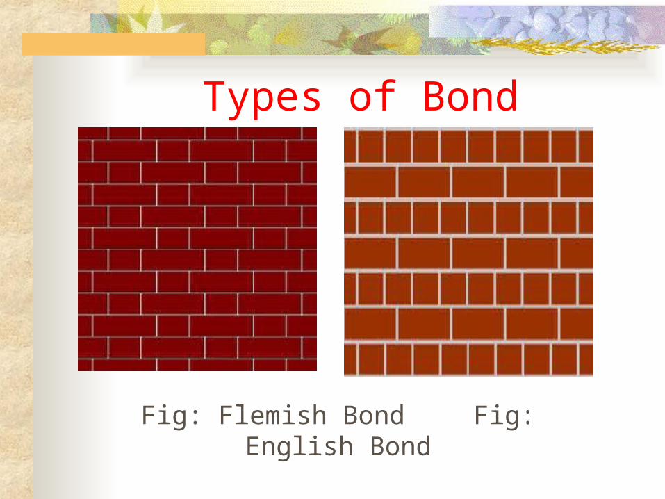
Types of Bond
Fig: Flemish Bond Fig: English Bond

S.N. English bond S.N. Flemish bond1 Headers and stretchers are laid in
alternate courses.
1 Headers and stretchers are laid alternately in each course.
2 Strongest of the types of bonds. 2 Comparatively less strong for walls more than 30cm thick.
3 Provides rough appearance. 3 Provide good appearance.4 Absence of vertical joints in the
structure.
4 Partly continuous vertical joints appear in the structure.
5 Special attention is not required for this bond.
5 Special attention is required for this bond.
6 Progress of work is more. 6 Progress of work is less.7 Costly, no brick bats are used. 7 Economical, as brick bats are used.8 Skilled labor is not required for its
construction
8 Skilled labor required for its construction.
9 Less mortar is used. 9 More mortar is used due to use of bats.

Rat-trap bond Shiner and rowlock are visible on the face of
masonry; this gives the wall with an internal cavity bridged by the Rowlock.
Economic use of brick. The cavity provides thermal comfort inside the wall. Used in load bearing as well as thick partition wall. The structural strength increased by inserting steel. Due to cavity, the weight of the building is reduced. Aesthetically pleasing wall.

Rat-trap bond
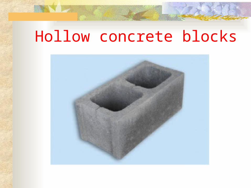
Hollow concrete blocks

Advantage of Hollow concrete blocks Hollow block needs low maintenance. High Durable. Construction speed is high when compare to conventional construction
systems. It has high tensile strength. Economical friendly and cheap rates. It reduces the building costs. The acoustic system of the room is good with hollow cement construction. Maintains the thermal balance system of any hollow block construction. It reduces the labor cost and total construction cost. High heat and water resistant. It’s no needs of plastering Low water absorption than brick. Main advantage, block voids can be filled by other filling materials.

Compressed Earth Block
Advantage of Compressed Earth Block Shipping cost: Suitable soils are often available at or near the
construction site. Uniformity: Manufactured to a predictable size and has true flat
sides and 90-degree angle edges. Non-toxic: Materials are completely natural, non-toxic,
chemical-free, and do not out-gas. Sound resistant: An important feature in high-density
neighborhoods, residential areas adjacent to industrial zones. Fire resistant: Earthen walls do not burn. Insect resistant: Insects are discouraged since the walls are solid
and very dense, and have no food value. Reduction in transportation cost due to locally available
material used.

Masonry as infill walls

Masonry as infill walls Masonry in-fills cause undesirable effects under seismic loading:
short-column effect, soft-storey effect, torsion, and out-of-plane collapse.
In-fills are separated from the RC frame and do not interfere with the frame under lateral deformations. All lateral force on the building is carried by the bare RC frame alone.
In-fills are built integral with the RC frame as non-structural elements. The entire lateral force on the building is carried by the bare RC frame alone. Most common design practice in the developing countries.
In-fills are built integral with the RC frame, and considered as structural elements. In-plane stiffness offered by the infill walls is considered in analysis. The forces from this analysis are used in the design of RC frame members and joints.

Reinforced masonry A construction system where steel
reinforcement is embedded in the mortar joints of masonry or placed in holes and after filled with concrete or grout is called Reinforced masonry. Reinforced masonry can be classified into three types:
Reinforced hollow unit masonry Reinforced grouted cavity masonry Reinforced pocket type walls

Reinforced grouted cavity masonry

Reinforced pocket cavity masonry construction

Typical anchorages of reinforcing bars

Unreinforced masonry Likely to be damaged during earthquake. Mortar holding the masonry together is generally
not strong enough to resist earthquake forces. Anchorage of walls to the floor and the roof is
critical. These houses are weak (brittle) and can break
apart. Walls may fall away or buckle, resulting in
damage.

Unreinforced masonry

Confined masonry The masonry walls carry the seismic loads and the concrete is
used to confine the walls. Construction system where masonry structural walls are
surrounded on all four sides with reinforced concrete. Confinement should be in vertical and horizontal both
direction to resists lateral and gravity loads. The confining members are effective for:
1. Enhancing the stability and integrity of masonry wall for in-plane and out-of-plane earthquake loads.
2. Enhancing the strength of masonry wall under EQ.
3. Reducing brittleness of masonry improving EQ performance.

Confined masonry The structural component of confined masonry are: Masonry wall Confining elements (tie-beams and tie columns) Floor and roof slab Plinth band Foundation

Confined masonry

Chapter-08
Design of masonry walls for gravity
loadsIS1905-1987

Introduction to Codal Provisions
Scope Structural design of unreinforced load
bearing and non-load bearing walls constructed with solid or perforated burnt clay brick, concrete block.
Do not apply to walls constructed in mud mortars.

Walls Most essential component of building. Enclose or divide space of building. Provide privacy, afford security and protection
against heat, rain and cold. Designed wall should have
A. Strength and stability
B. Weather resistance and thermal insulation
C. Durability and fire resistance
D. Sound insulation

Walls Vertical load-bearing member, the width of
which (length) exceeds 4 times the thickness. Isolated vertical load bearing member, the
width of which does not exceed 4 times the thickness is called column.
Types of walls Load-bearing wall- Designed to carry super-
imposed load and self weight. Non-load bearing wall- Designed to carry self
weigh only.

Walls Partition wall: Thin internal wall used to divide the space within
building. Internal wall: Load bearing partition wall. Panel wall: External non-load bearing wall (commonly related to
frame structure) Party wall: Wall separating the adjoining buildings. May or may
not be load bearing. Separating wall: Wall separation different occupancies within the
same building. Curtain wall: Self-supporting wall carrying no other vertical load
but subject to lateral loads. E:\File\code\codes\1905.PDF Cross-walls: Load bearing walls construction in which all the
loads are carried by internal walls, running at right angles to the length of building.

Load bearing Walls Solid masonry walls: Most commonly used but may have opening. Cavity walls: Wall comprising two leaves, each leave being build
of masonry units and separated by a cavity and tied together with metal ties or bonding units to ensure that two leaves act as one structural units. Space between two leaves being left continuous or filled with other non-load bearing insulating material.
Solid WallCavity Wall

Load bearing Walls Faced walls: Wall in which the facing and backing are of two
different materials are bonded together to ensure common action.(IS1905 Figure 3, pageno.4)
E:\File\code\codes\1905.PDF Veneered walls: Wall in which facing is attached to the backing
but not so bonded as to result in a common action under load.

Design ConsiderationGeneral Masonry structure gain stability from the
supports offered by cross walls, floors, roofs and other elements.
Structure is so planned that eccentricity of loading on the members is small as possible.
Mix proportions should follow Table 1 (IS1905-1987) page no. 6

Design Consideration cont…Selection of mortar Requirement of mortar for masonry structure workability,
strength, water retentively and low drying shrinkage. Mortar strength in general should not be greater than that of
masonry unit.Masonry unit strength (N/mm2)
Mortar type
Below 5 M2
5 to 14.9 M1
15-24.9 H2
25 or above H1
Letter H, M and L indicates the high strength, medium strength and low strength

Design Consideration cont….Stability requirement
Lateral support: Wall can be laterally supported either at vertical intervals by floor roof transmitting horizontal forces to cross-walls and then to the foundation or at horizontal interval by cross-wall, piers transmitting horizontal forces to foundations. Lateral support has to perform two important functions as:
To resist horizontal components of the forces so as to ensure the structure against over-turning.
To limit the slenderness ratio of masonry elements in order to prevent failure by buckling.
Adequate lateral support: If supports is capable of resisting the sum of following lateral forces than wall considered as adequate lateral support.
Simple static reactions at the point of lateral support to all the lateral loads.
2.5% of the total vertical load that the wall or column is designed to carry at the point of lateral support.

Design Consideration cont….Effective Height of wall The effective height of a load bearing wall is assessed based on the relative
stiffness of the elements of the structure connected to the wall together with the efficiency of the connection.
A wall is stiffened by floors , or roofs , suitable cross walls or any similar construction element.
Refer: Effective height of wall- Table 4 (IS1905-1987) page no .11E:\File\code\codes\1905.PDF

Design Consideration cont….Effective length of wall
Refer: Effective length of wall- Table 5 (IS1905-1987) Page no. 12
Effective thickness of wall
Refer: Effective thickness of wall (Clause 4.5 of IS1905-1987) Page no: 13
Slenderness ratio (SR)
The ratio of effective height or effective length to the effective thickness of wall whichever is less is the design value of slenderness ratio.
The slenderness ratio for a load bearing column shall not exceed 12.
Maximum SR for a load bearing wall
No of Storey Maximum Slenderness Ratio
Using Portland cement in mortar Using mortar lime
Not exceeding 2 27 20
Exceeding 2 27 13
Refer: Table 7 (IS 1905-1987)
Eccentricity: Clause 4.7 IS1905 E:\File\code\codes\1905.PDF

Structural DesignGeneral Analyzed by accepted principle of mechanics to ensure safe and
proper functioning in service of its components. All components shall be capable of sustaining the most adverse
combinations of loads, which the structure reasonably expected to be subjected to during and after construction.
Design Loads Dead load of walls, columns, floors and roofs. Live load on floor and roof. (Calculated by using IS875 II) Wind load on walls and sloping roof. Seismic forces (In zone I and II, not necessary and zone III, IV
and IV should adopted)
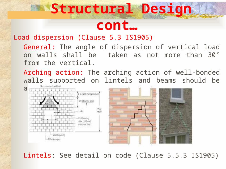
Structural Design cont…Load dispersion (Clause 5.3 IS1905)
General: The angle of dispersion of vertical load on walls shall be taken as not more than 30° from the vertical.
Arching action: The arching action of well-bonded walls supported on lintels and beams should be account.
Lintels: See detail on code (Clause 5.5.3 IS1905)

Structural Design cont….Permissible stresses (Clause 5.4 IS1905)
Permissible compressive stress (clause 5.4.1)
Permissible compressive stress = Fb*Ks*Ka*Ks, where The basic compressive stress based on type and strength of the
masonry units and mix of mortar, Fb (Table 8)
Stress reduction factor (Ks) depends on SR and eccentricity of loading (Table 9)
Area reduction factor (Ka), Ka = 0.7 +1.5A, A= area in m2 Shape reduction factor (Ks), (Table 10)
Permissible tensile stress (Clause 5.4.2)
Permissible shear stress (clause 5.4.3)
Fa =0.1+Fd/6 ≤0.5N/mm2 , Fa =permissible shear stress,
Fd =compressive stress due to dead load

Wall OpeningEffect of openingsReduce lateral strength of URM
walls and should be small & centrally located.
Total length of openings should be half for one-storey and one-third for two- storey Buildings.

Refer: NBC 109
Related Documents