M.A.R.V.E.L. – INTELLIGENT DEMAND CONTROLLED VENTILATION SYSTEM FOR PROFESSIONAL KITCHENS N. Vodopivec Halton Foodservice GmbH, Germany Goap d.o.o. Nova Gorica, Ulica Klementa Juga 007, 5250 Solkan, Slovenija E-mail: [email protected] ABSTRACT: Model-based Automated Regulation of Ventilation Exhaust Level (M.A.R.V.E.L.) offers individual exhaust airflow management in real time on each canopy, connected to a unique exhaust fan, installed in a kitchen. It is able to identify the current status of cooking equipment - switched off, heating to the cooking temperature or cooking in progress. In combination with the Capture Jet3® technology, it offers the highest energy savings with up to 65% reduction of exhaust airflow rates. Permanent optimization of the power consumption of the fan motors can be achieved thanks to a variable air flow rate and air pressure regulation. M.A.R.V.E.L. system is at the top of all actual energetic trends and requirements and is a revolution dragging kitchens in a green building circle. Keywords: M.A.R.V.E.L., Capture Jet3®, cooking equipment status, variable airflow, pressure regulation, energy saving. 1. INTRODUCTION In Institutional kitchens, cooking represents only 25% of total energy consumption while heating, ventilation, and air conditioning represent 30% of total energy consumption [1]. A free convection flow forms above each kitchen appliance due to difference in temperature and density of air between ambient air and the air which warms up on contact with cooking appliances. The flow pattern forms a plume which concentrates all thermal and weight transfers. The plume is fed with ambient air from the ground [2] as seen on Figure 1. An exhaust fan in the ceiling could easily remove the heat produced by cooking equipment. But mix in smoke, volatile organic compounds, grease particles and vapor from cooking, a means to capture and contain the effluent is needed to avoid health and fire hazards. While an exhaust hood serves that purpose, the key question is always: what is the appropriate exhaust rate? [3]

Welcome message from author
This document is posted to help you gain knowledge. Please leave a comment to let me know what you think about it! Share it to your friends and learn new things together.
Transcript
M.A.R.V.E.L. – INTELLIGENT DEMAND CONTROLLED VENTILATION SYSTEM
FOR PROFESSIONAL KITCHENS
N. Vodopivec
Halton Foodservice GmbH, Germany Goap d.o.o. Nova Gorica, Ulica Klementa Juga 007, 5250 Solkan, Slovenija
E-mail: [email protected]
ABSTRACT: Model-based Automated Regulation of Ventilation Exhaust Level (M.A.R.V.E.L.) offers individual exhaust airflow management in real time on each canopy, connected to a unique exhaust fan, installed in a kitchen. It is able to identify the current status of cooking equipment - switched off, heating to the cooking temperature or cooking in progress. In combination with the Capture Jet3® technology, it offers the highest energy savings with up to 65% reduction of exhaust airflow rates. Permanent optimization of the power consumption of the fan motors can be achieved thanks to a variable air flow rate and air pressure regulation. M.A.R.V.E.L. system is at the top of all actual energetic trends and requirements and is a revolution dragging kitchens in a green building circle. Keywords: M.A.R.V.E.L., Capture Jet3®, cooking equipment status, variable airflow, pressure regulation, energy saving.
1. INTRODUCTION
In Institutional kitchens, cooking represents only 25% of total energy consumption while heating, ventilation, and air conditioning represent 30% of total energy consumption [1].
A free convection flow forms above each kitchen appliance due to difference in temperature and density of air between ambient air and the air which warms up on contact with cooking appliances. The flow pattern forms a plume which concentrates all thermal and weight transfers. The plume is fed with ambient air from the ground [2] as seen on Figure 1.
An exhaust fan in the ceiling could easily remove the heat produced by cooking equipment. But mix in smoke, volatile organic compounds, grease particles and vapor from cooking, a means to capture and contain the effluent is needed to avoid health and fire hazards. While an exhaust hood serves that purpose, the key question is always: what is the appropriate exhaust rate? [3]
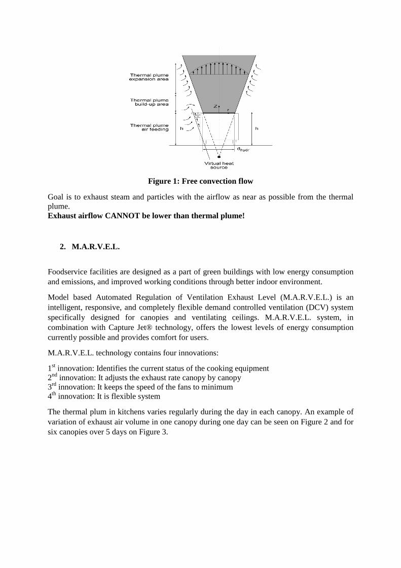
Figure 1: Free convection flow
Goal is to exhaust steam and particles with the airflow as near as possible from the thermal plume. Exhaust airflow CANNOT be lower than thermal plume!
2. M.A.R.V.E.L.
Foodservice facilities are designed as a part of green buildings with low energy consumption and emissions, and improved working conditions through better indoor environment.
Model based Automated Regulation of Ventilation Exhaust Level (M.A.R.V.E.L.) is an intelligent, responsive, and completely flexible demand controlled ventilation (DCV) system specifically designed for canopies and ventilating ceilings. M.A.R.V.E.L. system, in combination with Capture Jet® technology, offers the lowest levels of energy consumption currently possible and provides comfort for users.
M.A.R.V.E.L. technology contains four innovations:
1st innovation: Identifies the current status of the cooking equipment 2nd innovation: It adjusts the exhaust rate canopy by canopy 3rd innovation: It keeps the speed of the fans to minimum 4th innovation: It is flexible system
The thermal plum in kitchens varies regularly during the day in each canopy. An example of variation of exhaust air volume in one canopy during one day can be seen on Figure 2 and for six canopies over 5 days on Figure 3.
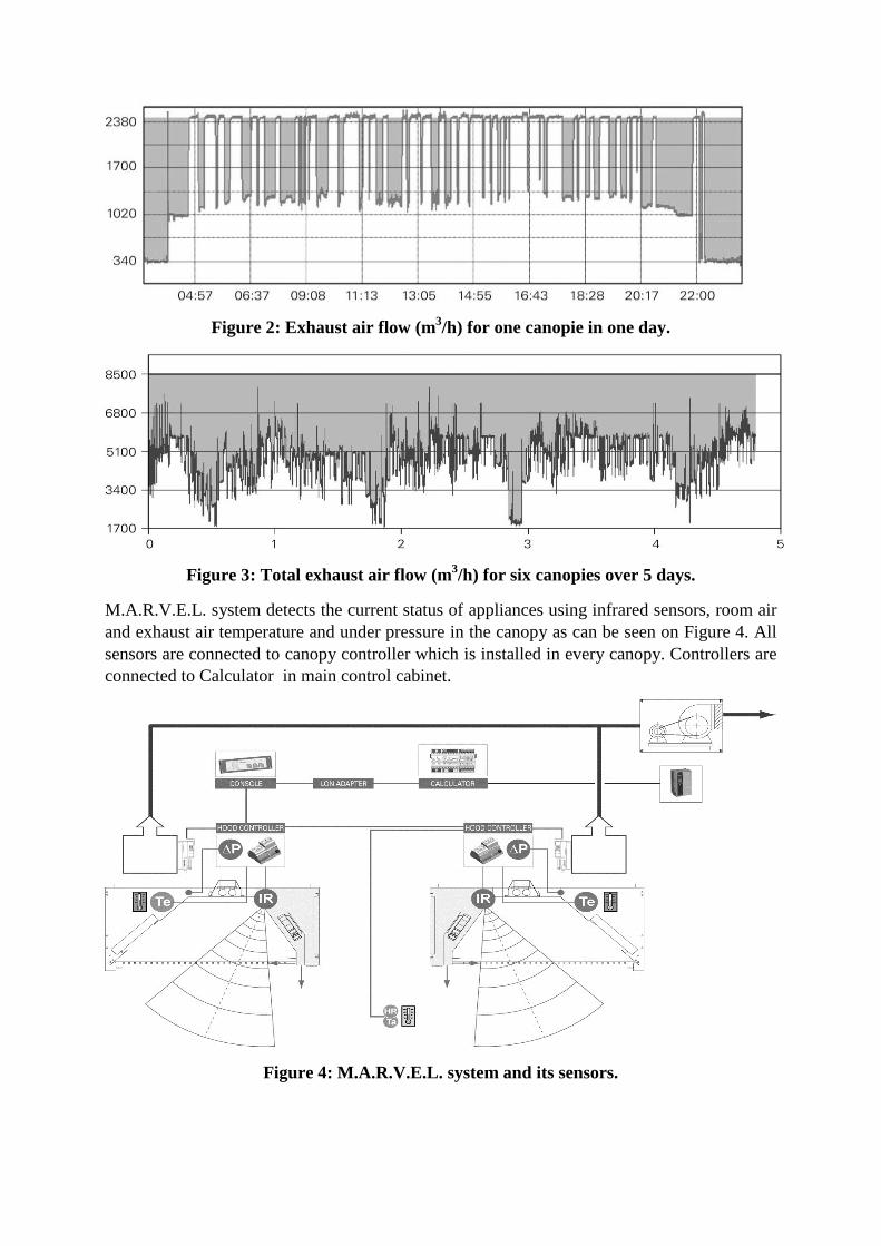
Figure 2: Exhaust air flow (m3/h) for one canopie in one day.
Figure 3: Total exhaust air flow (m3/h) for six canopies over 5 days.
M.A.R.V.E.L. system detects the current status of appliances using infrared sensors, room air and exhaust air temperature and under pressure in the canopy as can be seen on Figure 4. All sensors are connected to canopy controller which is installed in every canopy. Controllers are connected to Calculator in main control cabinet.
Figure 4: M.A.R.V.E.L. system and its sensors.
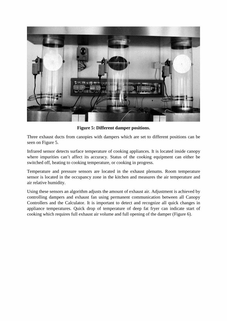
Figure 5: Different damper positions.
Three exhaust ducts from canopies with dampers which are set to different positions can be seen on Figure 5.
Infrared sensor detects surface temperature of cooking appliances. It is located inside canopy where impurities can’t affect its accuracy. Status of the cooking equipment can either be switched off, heating to cooking temperature, or cooking in progress.
Temperature and pressure sensors are located in the exhaust plenums. Room temperature sensor is located in the occupancy zone in the kitchen and measures the air temperature and air relative humidity.
Using these sensors an algorithm adjusts the amount of exhaust air. Adjustment is achieved by controlling dampers and exhaust fan using permanent communication between all Canopy Controllers and the Calculator. It is important to detect and recognize all quick changes in appliance temperatures. Quick drop of temperature of deep fat fryer can indicate start of cooking which requires full exhaust air volume and full opening of the damper (Figure 6).
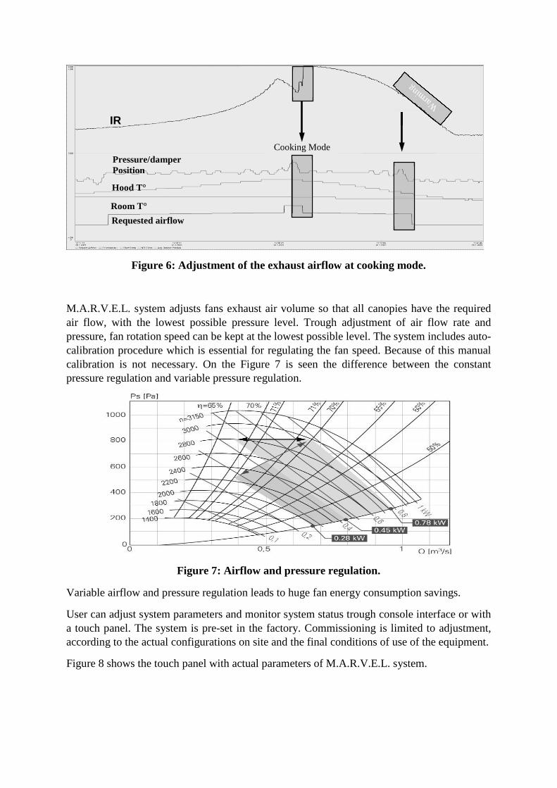
Figure 6: Adjustment of the exhaust airflow at cooking mode.
M.A.R.V.E.L. system adjusts fans exhaust air volume so that all canopies have the required air flow, with the lowest possible pressure level. Trough adjustment of air flow rate and pressure, fan rotation speed can be kept at the lowest possible level. The system includes auto-calibration procedure which is essential for regulating the fan speed. Because of this manual calibration is not necessary. On the Figure 7 is seen the difference between the constant pressure regulation and variable pressure regulation.
Figure 7: Airflow and pressure regulation.
Variable airflow and pressure regulation leads to huge fan energy consumption savings.
User can adjust system parameters and monitor system status trough console interface or with a touch panel. The system is pre-set in the factory. Commissioning is limited to adjustment, according to the actual configurations on site and the final conditions of use of the equipment.
Figure 8 shows the touch panel with actual parameters of M.A.R.V.E.L. system.
IR
Room T°
Hood T°
Pressure/damper Position
Requested airflow
Cooking Mode
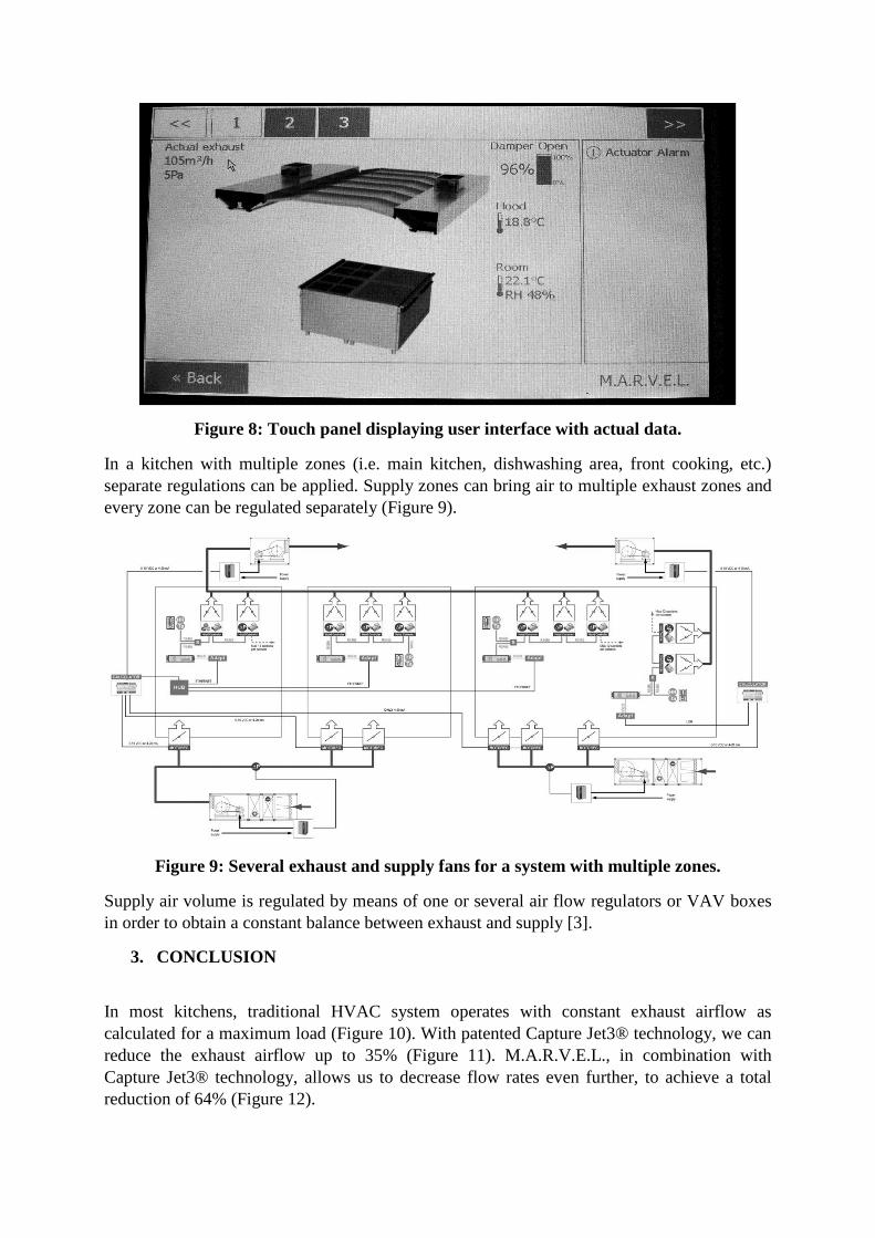
Figure 8: Touch panel displaying user interface with actual data.
In a kitchen with multiple zones (i.e. main kitchen, dishwashing area, front cooking, etc.) separate regulations can be applied. Supply zones can bring air to multiple exhaust zones and every zone can be regulated separately (Figure 9).
Figure 9: Several exhaust and supply fans for a system with multiple zones.
Supply air volume is regulated by means of one or several air flow regulators or VAV boxes in order to obtain a constant balance between exhaust and supply [3].
3. CONCLUSION
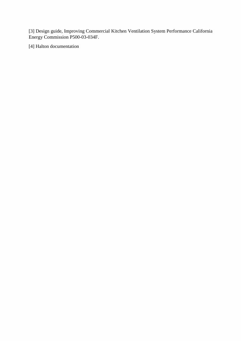
In most kitchens, traditional HVAC system operates with constant exhaust airflow as calculated for a maximum load (Figure 10). With patented Capture Jet3® technology, we can reduce the exhaust airflow up to 35% (Figure 11). M.A.R.V.E.L., in combination with Capture Jet3® technology, allows us to decrease flow rates even further, to achieve a total reduction of 64% (Figure 12).
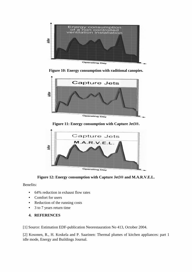
Figure 10: Energy consumption with raditional canopies.
Figure 11: Energy consumption with Capture Jet3®.
Figure 12: Energy consumption with Capture Jet3® and M.A.R.V.E.L.
Benefits:
· 64% reduction in exhaust flow rates · Comfort for users · Reduction of the running costs · 3 to 7 years return time
4. REFERENCES
[1] Source: Estimation EDF-publication Neorestauration No 413, October 2004.
[2] Kosonen, R., H. Koskela and P. Saarinen: Thermal plumes of kitchen appliances: part 1 idle mode, Energy and Buildings Journal.
[3] Design guide, Improving Commercial Kitchen Ventilation System Performance California Energy Commission P500-03-034F.
[4] Halton documentation
Related Documents