smd ilm caPacitors GEnEral tEchnical inormation MaRKIng oF SMD CapaCItoRS Tolerance Capacitance marked acc. to EIA standard Rated voltage Type Manufacturing year Testing month 103 H ZSKD 103 HZM Chip length 5.7 mm Chip length ≥ 7.3 mm The e ge is expressed with letter codes: Z 50 VDC H 250 VDC C 63 VDC K 400 VDC D 100 VDC M 630 VDC F 160 VDC P 1000 VDC W 12 00 VDC The nominal pe ue is given with 3 digits EIA-code, Epe: 103 = 10000 pF = 10 nF = 0.01 µF The pe ee is expressed with letter codes: M ± 20 % H ± 2.5 % K ± 10 % G ± 2 % J ± 5 % F ± 1 % The p ype codes are as ollows: M MMC P GPC S SMC, SMW D SPC G GMC, GMW The uug ye and the eg are expressed according to IEC 60062, see table on page 10. SoLDERIng oF wounD SMD CapaCItoRS The recommended soldering land dimensions are: W X X A Ah = horizontal mounting Av = vertical mounting l ce ze W a a x hz ve 5.7 2220 - J31, J91 60 1.5 200 5.1 118.58 3.0 5.7 2220 - J33, J93 60 1.5 200 5.1 118.58 3.0 5.7 2220 - J35, J95 60 1.5 200 5.1 118.58 3.0 7.3 2824 - K31, K91 60 1.5 240 6.1 148.11 3.8 7.3 2824 - K33, K93 60 1.5 240 6.1 148.11 3.8 7.3 2824 - K35, K95 60 1.5 240 6.1 148.11 3.8 7.3 2824 - K37, K97 60 1.5 240 6.1 148.11 3.8 10.2 4036 - A31 4022 - A31V 80 2.0 360 9.1 220 5.6 217.15 5.5 12.7 5045 - B31 5026 - B31V 100 2.5 455 11.6 260 6.6 276.4 7.0 16.5 6560 - C31 6528 - C31V 120 3.0 590 15.0 280 7.1 355.3 9.0 Land dimensions or PCB design are available in PADS ormat.

Welcome message from author
This document is posted to help you gain knowledge. Please leave a comment to let me know what you think about it! Share it to your friends and learn new things together.
Transcript

8/4/2019 Marking of SMD Capacitor
http://slidepdf.com/reader/full/marking-of-smd-capacitor 1/3
smd ilm caPacitors
GEnEral tEchnical inormation
MaRKIng oF SMD CapaCItoRS
Tolerance
Capacitance marked
acc. to EIA standard
Rated voltage
Type
Manufacturing year
Testing month
103 HZ S K D
103H Z M
Chip length 5.7 mm Chip length ≥ 7.3 mm
The e ge is expressed with letter codes:
Z 50 VDC H 250 VDC
C 63 VDC K 400 VDC
D 100 VDC M 630 VDC
F 160 VDC P 1000 VDC
W 12 00 VDC
The nominal pe ue is given with 3 digits EIA-code,Epe: 103 = 10000 pF = 10 nF = 0.01 µF
The pe ee is expressed with letter codes:
M ± 20 % H ± 2.5 %
K ± 10 % G ± 2 %J ± 5 % F ± 1 %
The p ype codes are as ollows:
M MMC P GPC
S SMC, SMW D SPC
G GMC, GMW
The uug ye and the eg are expressedaccording to IEC 60062, see table on page 10.
SoLDERIng oF wounD SMD CapaCItoRS
The recommended soldering land dimensions are:
W
X X
A
Ah = horizontal mounting
Av = vertical mounting
l ce ze W a a x
hz ve
5.7 2220 - J31, J91 60 1.5 200 5.1 118.58 3.0
5.7 2220 - J33, J93 60 1.5 200 5.1 118.58 3.0
5.7 2220 - J35, J95 60 1.5 200 5.1 118.58 3.07.3 2824 - K31, K91 60 1.5 240 6.1 148.11 3.8
7.3 2824 - K33, K93 60 1.5 240 6.1 148.11 3.8
7.3 2824 - K35, K95 60 1.5 240 6.1 148.11 3.8
7.3 2824 - K37, K97 60 1.5 240 6.1 148.11 3.8
10.2 4036 - A31 4022 - A31V 80 2.0 360 9.1 220 5.6 217.15 5.5
12.7 5045 - B31 5026 - B31V 100 2.5 455 11.6 260 6.6 276.4 7.0
16.5 6560 - C31 6528 - C31V 120 3.0 590 15.0 280 7.1 355.3 9.0
Land dimensions or PCB design are available in PADS ormat.
8/4/2019 Marking of SMD Capacitor
http://slidepdf.com/reader/full/marking-of-smd-capacitor 2/3Evox Rifa SMD and DIL Film Capacitors
1
smd ilm caPacitors
GEnEral tEchnical inormation
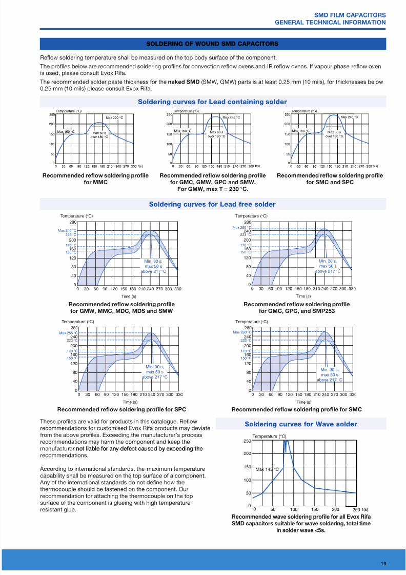
reee ew eg pfe GmW, mmc, mdc, mds smW
reee ew eg pfe Gmc, GPc, smP253
reee ew eg pfe sPc
Temperature ( °C)
200
25050 100 t(s)150 200
150
100
50
250
00
Max 145 °C
recoene wave oleing pofle o all Evox ria
smd capacito uitable o wave oleing, total tie
in ole wave <5.
SoLDERIng oF wounD SMD CapaCItoRS
Temperature (°C)
200
30 60 90 120 150 180 210
160
120
40
80
240 270 3303000
280
0
Time (s)
150 °C
170 °C
223 °CMax 240 °C
Min. 30 s,
max 50 s
above 217 °C
Temperature (°C)
200
240
30 60 90 120 150 180 210
160
120
40
80
240 270 3303000
280
0
Time (s)
150 °C
170 °C
223 °C
Max 250 °C
Min. 30 s,
max 50 s
above 217 °C
Temperature (°C)
200
240
30 60 90 120 150 180 210
160
120
40
80
240 270 3303000
280
0
Time (s)
150 °C
170 °C
223 °C
Max 255 °C
Min. 30 s,
max 50 s
above 217 °C
Temperature (°C)
200
240
30 60 90 120 150 180 210
160
120
40
80
240 270 3303000
280
0
Time (s)
150 °C
170 °C
223 °C
Max 260 °C
Min. 30 s,
max 50 s
above 217 °C
reee ew eg pfe smc
These proles are valid or products in this catalogue. Refowrecommendations or customised Evox Ria products may deviaterom the above proles. Exceeding the manuacturer’s processrecommendations may harm the component and keep themanuacturer not liable or any deect caused by exceeding thenot liable or any deect caused by exceeding therecommendations.
According to international standards, the maximum temperaturecapability shall be measured on the top surace o a component.
Any o the international standards do not dene how thethermocouple should be astened on the component. Ourrecommendation or attaching the thermocouple on the top
surace o the component is glueing with high temperatureresistant glue.
Refow soldering temperature shall be measured on the top body surace o the component.
The proles below are recommended soldering proles or convection refow ovens and IR refow ovens. I vapour phase refow ovenis used, please consult Evox Ria.
The recommended solder paste thickness or the ke smd (SMW, GMW) parts is at least 0.25 mm (10 mils), or thicknesses below0.25 mm (10 mils) please consult Evox Ria.
Temperature (°C)
200
30 60 90 120 150 180 210 t(s)
150
100
50
240 270 3000
250
0
Max 150 °C
Max 220 °C
Max 60 s
over 180 °C
reee ew eg pfe
mmc
Temperature (°C)
200
30 60 90 120 150 180 210 t(s)
150
100
50
240 270 3000
250
0
Max 150 °C
Max 235 °C
Max 60 s
over 180 °C
reee ew eg pfe
Gmc, GmW, GPc smW.
GmW, t = 230 °c.
Temperature (°C)
200
30 60 90 120 150 180 210 t(s)
150
100
50
240 270 3000
250
0
Max 160 °C
Max 240 °C
Max 60 s
over 180 °C
reee ew eg pfe
smc sPc
Slderi crves fr wve slder
Slderi crves fr Led cii slder
Slderi crves fr Led free slder
8/4/2019 Marking of SMD Capacitor
http://slidepdf.com/reader/full/marking-of-smd-capacitor 3/3
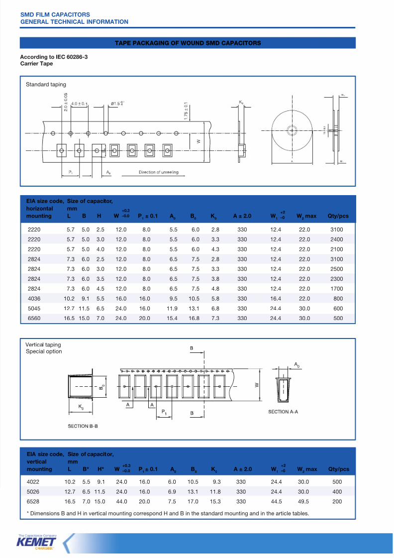
4022 10.2 5.5 9.1 24.0 16.0 6.0 10.5 9.3 330 24.4 30.0 500
5026 12.7 6.5 11.5 24.0 16.0 6.9 13.1 11.8 330 24.4 30.0 400
6528 16.5 7.0 15.0 44.0 20.0 7.5 17.0 15.3 330 44.5 49.5 200
* Dimensions B and H in vertical mounting correspond H and B in the standard mounting and in the article tables.
smd ilm caPacitors
GEnEral tEchnical inormation
tapE paCKagIng oF wounD SMD CapaCItoRS
1
ag iEc 60286-3
ce tpe
2220 5.7 5.0 2.5 12.0 8.0 5.5 6.0 2.8 330 12.4 22.0 3100
2220 5.7 5.0 3.0 12.0 8.0 5.5 6.0 3.3 330 12.4 22.0 2400
2220 5.7 5.0 4.0 12.0 8.0 5.5 6.0 4.3 330 12.4 22.0 2100
2824 7.3 6.0 2.5 12.0 8.0 6.5 7.5 2.8 330 12.4 22.0 3100
2824 7.3 6.0 3.0 12.0 8.0 6.5 7.5 3.3 330 12.4 22.0 2500
2824 7.3 6.0 3.5 12.0 8.0 6.5 7.5 3.8 330 12.4 22.0 2300
2824 7.3 6.0 4.5 12.0 8.0 6.5 7.5 4.8 330 12.4 22.0 1700
4036 10.2 9.1 5.5 16.0 16.0 9.5 10.5 5.8 330 16.4 22.0 800
5045 12.7 11.5 6.5 24.0 16.0 11.9 13.1 6.8 330 24.4 30.0 600
6560 16.5 15.0 7.0 24.0 20.0 15.4 16.8 7.3 330 24.4 30.0 500
Standard taping
Vertical tapingSpecial option
Eia ze e, sze p,
z
ug l B h W P1
± 0.1 a0
B0
K0
a ± 2.0 W1
W2
Qy/p+2
–0
+0.3
–0.0
+2
–0
+0.3
–0.0
Eia ze e, sze p,
e
ug l B* h* W P1± 0.1 a
0B
0K
0a ± 2.0 W
1W
2 Qy/p
Related Documents