Procedia Engineering 72 (2014) 344 – 349 1877-7058 © 2014 Published by Elsevier Ltd. Open access under CC BY-NC-ND license. Selection and peer-review under responsibility of the Centre for Sports Engineering Research, Sheffield Hallam University doi:10.1016/j.proeng.2014.06.060 ScienceDirect The 2014 conference of the International Sports Engineering Association Markerless tracking of tennis racket motion using a camera Nathan Elliott a, *, Simon Choppin a , Simon R. Goodwill a , Tom Allen a,b a Centre for Sports Engineering Research, Sheffield Hallam University, Sheffield S10 2BP, UK b Department of Engineering and Maths, Sheffield Hallam University, Sheffield S1 1WB, UK Abstract This research is concerned with tracking tennis racket movements. Previously, stereo camera systems have been used to track markers attached to rackets, which allows for racket movements to be obtained in three-dimensions. Typically, markers are manually selected on the image plane but this can be time consuming and inaccurate. This paper discusses a markerless method to measure three-dimensional racket movements using a camera. The method relies on a silhouette of a racket captured with a camera whose relative pose (rotation and translation) is unknown. A candidate relative pose is used to measure the inconsistency between the silhouette and a set of racket silhouettes captured with a fully calibrated camera. The measure of inconsistency can be formulated as a cost function associated with the candidate relative pose. By adjusting parameters of the pose to minimise the cost, an accurate estimation for the true pose of the racket can be made. A validation scheme was developed to compare pose estimates with data obtained using camera calibration software. Rotation about the axis of x, y, z' were accurate to within 2.5° for 88, 90 and 86 % of estimates respectively and resultant translation to within 5 mm for 72% of estimates. This research is the first step in a process to fully validate a novel method for measuring tennis racket movements in real play conditions. © 2014 The Authors. Published by Elsevier Ltd. Selection and peer-review under responsibility of the Centre for Sports Engineering Research, Sheffield Hallam University. Keywords: markerless; silhouette; pose; inconsistency 1. Introduction Player testing is an important tool to help understand the effect of racket parameters on rebound ball dynamics in real play conditions. Previously, photogrammetric player testing has been performed in two-dimensions (2D) at * Corresponding author. Tel.:+44 0114 225 5867. E-mail address: [email protected] © 2014 Published by Elsevier Ltd. Open access under CC BY-NC-ND license. Selection and peer-review under responsibility of the Centre for Sports Engineering Research, Sheffield Hallam University Available online at www.sciencedirect.com

Welcome message from author
This document is posted to help you gain knowledge. Please leave a comment to let me know what you think about it! Share it to your friends and learn new things together.
Transcript
Procedia Engineering 72 ( 2014 ) 344 – 349
1877-7058 © 2014 Published by Elsevier Ltd. Open access under CC BY-NC-ND license.
Selection and peer-review under responsibility of the Centre for Sports Engineering Research, Sheffield Hallam University
doi: 10.1016/j.proeng.2014.06.060
ScienceDirect
The 2014 conference of the International Sports Engineering Association
Markerless tracking of tennis racket motion using a camera
Nathan Elliotta,*, Simon Choppin
a, Simon R. Goodwill
a, Tom Allen
a,b
aCentre for Sports Engineering Research, Sheffield Hallam University, Sheffield S10 2BP, UK bDepartment of Engineering and Maths, Sheffield Hallam University, Sheffield S1 1WB, UK
Abstract
This research is concerned with tracking tennis racket movements. Previously, stereo camera systems have been used to track
markers attached to rackets, which allows for racket movements to be obtained in three-dimensions. Typically, markers are
manually selected on the image plane but this can be time consuming and inaccurate. This paper discusses a markerless method
to measure three-dimensional racket movements using a camera. The method relies on a silhouette of a racket captured with a
camera whose relative pose (rotation and translation) is unknown. A candidate relative pose is used to measure the
inconsistency between the silhouette and a set of racket silhouettes captured with a fully calibrated camera. The measure of
inconsistency can be formulated as a cost function associated with the candidate relative pose. By adjusting parameters of the
pose to minimise the cost, an accurate estimation for the true pose of the racket can be made. A validation scheme was
developed to compare pose estimates with data obtained using camera calibration software. Rotation about the axis of x, y, z'
were accurate to within 2.5° for 88, 90 and 86 % of estimates respectively and resultant translation to within 5 mm for 72% of
estimates. This research is the first step in a process to fully validate a novel method for measuring tennis racket movements in
real play conditions.
© 2014 The Authors. Published by Elsevier Ltd.
Selection and peer-review under responsibility of the Centre for Sports Engineering Research, Sheffield Hallam University.
Keywords: markerless; silhouette; pose; inconsistency
1. Introduction
Player testing is an important tool to help understand the effect of racket parameters on rebound ball dynamics
in real play conditions. Previously, photogrammetric player testing has been performed in two-dimensions (2D) at
* Corresponding author. Tel.:+44 0114 225 5867.
E-mail address: [email protected]
© 2014 Published by Elsevier Ltd. Open access under CC BY-NC-ND license.
Selection and peer-review under responsibility of the Centre for Sports Engineering Research, Sheffield Hallam University
Available online at www.sciencedirect.com
345 Nathan Elliott et al. / Procedia Engineering 72 ( 2014 ) 344 – 349
low (<200 fps) frame rates with a specific aim, whether this be analysis of player accuracy (Blievernicht 1968) or
studying player biomechanics (Knudson and Blackwell 2005). There has also been some notable three-dimensional
(3D) work focusing on the kinematics of the serve (Elliott 1986) and backhand (Elliott 1989). Sensor systems
capable of recording multiple points using 3D coordinates in real time have also been used to track racket and
upper limb movements. Mitchell et al. (2000) used a CODA (Cartesian optoelectronic dynamic anthropometer)
system to compare the effect of racket inertial properties on serve speed. Ahmadi et al. (2010) used two inertial
gyroscopes to measure upper arm rotation during the tennis serve. However, attaching sensors to the racket frame
and/or upper arm adds mass, altering inertial properties possibly influencing player swing mechanics. Brody
(2000) found that skilled tennis players were able to distinguish between rackets that differed by as little as 2.5% in
swingweight (moment of inertia about the racket handle end).
Camera systems are advantageous because they are easy to setup and less intrusive to the player compared with
sensor systems. Choppin (2008) developed a portable methodology for 3D player testing using two synchronised
high speed cameras to track reflective tape markers attached to the racket frame. Calibration using a checkerboard
(Zhang 1999) allowed for reconstruction of 3D coordinates from 2D position points so that racket and ball
movements could be measured. The method used manual digitisation to identify markers on the image plane which
can be time consuming and adds uncertainty.
Recently, markerless biomechanical analysis of the serve has been performed using a player's visual hull. A
visual hull is a 3D reconstruction of an object corresponding to a set of fully calibrated silhouette images
(Laurentini 1994). Previous authors placed 8 synchronised high speed cameras in known positions around a player
performing a serve to obtain a set of fully calibrated silhouettes (Abrams et al. 2011; Sheets et al. 2011).
Reconstruction for each time frame allowed joint centre position with six degrees of freedom and racket velocity to
be measured. Multiple camera systems are costly and lack portability making them impractical to be positioned
close to a player during real tennis play.
Price and Morrison (2007) present a method for calculating the 3D trajectory of a rigid particle using a camera.
With a set of fully calibrated silhouette images of the rigid particle, a pose estimation scheme based on silhouette
consistency produced 3D trajectories. The application of such a method to track movement of hand-held
implements used in sports has not yet been explored. Silhouettes contain information about an objects shape and
have potential to reduce inaccuracies associated with marker-based techniques. The aim of this paper was to
present a novel method to estimate racket pose based on silhouette consistency and validate the initial results.
2. Camera calibration
A camera is fully calibrated if its internal parameters (focal length, principle point and lens distortion) and the
external parameters (rotation and translation in a common reference frame) are known. The calibration procedure
used in this study was based on Zhang's algorithm (Zhang 1999) and used a planar calibration object. A first image
sequence involved capturing a checkerboard of known dimensions in 30 different orientations using a single-lens
reflex (SLR) camera (Cannon EOS 400D). The images were loaded into the Matlab (MATLAB R2011b,
MathWorks) camera calibration toolbox (Strobl et al. 2007) to provide enough data to iterate an accurate set of
internal calibration parameters from initial assumptions.
The calibration toolbox uses a highly repeatable automatic corner detection method to improve the accuracy of
the overall calibration. It was necessary to investigate whether the number of squares that made up the
checkerboard affected the reliability of the extrinsic parameters. An image of a checkerboard with 24 x 24 squares
was loaded into the software. The software was modified to accept instances where the number of squares along
each edge was 24, 12, 8, 6, 4, 3, 2 and 1. Over a mean of 3 extrinsic calibrations (3D location of the checkerboard
in the camera reference frame), for each checkerboard configuration the resultant translation varied by < 1 mm and
rotation by up to 0.3° about the axis of x, y, z' respectively. Therefore, the extrinsic calibration for the current study
could be performed using a board with a single rectangle with comparable reliability of a checkerboard with
multiple squares.
For the second image sequence, a model racket (110 x 150 mm) was fixed to a rigid board, with a 150 x 210
mm red rectangle printed beneath (Fig. 1(a)). Given the existing intrinsic parameters, the extrinsic parameters were

346 Nathan Elliott et al. / Procedia Engineering 72 ( 2014 ) 344 – 349
(a) (b)
Red rectangle
determined by manually selecting the four corners of the rectangle keeping the origin at the top left corner, which
was later moved to base of the racket handle. Silhouettes were extracted by removing the red colour channel from
the RGB (Red Green Blue) image before being converted to binary using a threshold operation. In total 44 views
of the racket were captured by moving the camera into different positions. This produced a well-distributed fully
calibrated silhouette set (Fig. 1(b)).
Fig.1. (a) Example of an image used to obtain the extrinsic parameters and (b) the 44 camera positions that formed the fully calibrated set
plotted in the global reference frame.
3. Racket pose estimation
A camera being moved with respect to a stationary racket is the same as a racket moving with respect to a
stationary camera. The relative pose (R and t) between the world and the reference frame of the camera can be
specified by a rigid body transformation
P = R tど な ,
where R is a 3 x 3 rotation matrix and t is a 3 x 1 translation vector. Therefore, the pose estimation problem
corresponds to finding appropriate values for R and t. The method relies on a silhouette of a racket captured with a
camera whose relative pose is unknown. A candidate relative pose is used to measure the inconsistency between
the silhouette and a set of racket silhouettes captured with a fully calibrated camera. The measure of inconsistency
will be based on the epipolar tangency error (ETE) which can be formulated as a cost function associated with the
candidate relative pose. By adjusting parameters of the pose to minimise the cost, an accurate estimation for the
true pose of the camera can be made.
3.1. The epipolar tangency error (ETE)
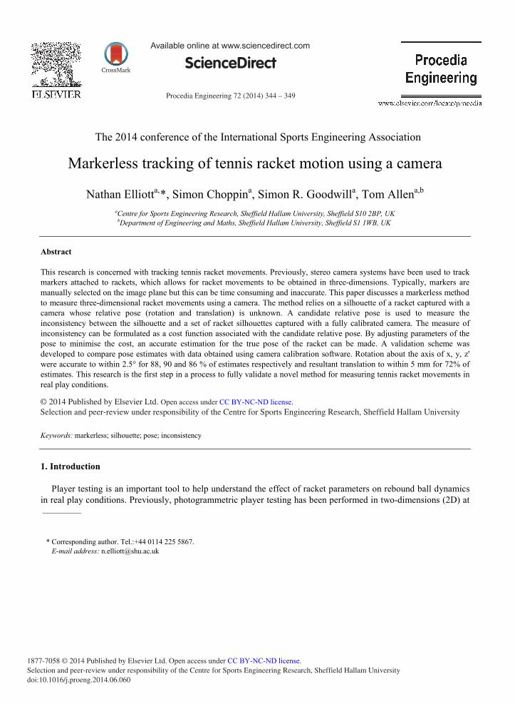
Consider two silhouette views of a racket shown in Fig. 2. The line joining the two camera centres C1 and C2 is
called the baseline. The projection of each camera centre into the opposite cameras image plane is called an
epipole. In Fig. 2, epipole e12 is the projection of C2 in the image plane of Camera 1, and epipole e21 is the
projection of C1in the image plane of Camera 2. The two planes 1 and 2 converge at the baseline and are tangent
to the racket. The 3D points P1 and P2 indicate where the planes touch the surface of the racket, and are referred to
as frontier points. Since the planes pass through both the camera centres and touch the surface of the racket, the
frontier points must project onto the boundaries of the silhouettes on both image planes. A projection of a frontier
point is called an epipolar tangency point. In Fig. 2, the tangency point's p1 and p'1 are projections of the frontier
point P1, and the tangency point's p2 and p'2 are projections of the frontier point P2, in the image planes of camera
1 and camera 2 respectively. Epipolar tangency lines are constructed by plotting a line from the epipoles to the
corresponding tangency points. Since these points are projections of the same 3D points, the viewing ray passing
(1)

347 Nathan Elliott et al. / Procedia Engineering 72 ( 2014 ) 344 – 349
through C2 and p'1must project exactly onto the epipolar tangency line e12p1. This is known as the epipolar
tangency constraint (Wong 2001) and applies to each of the four epipolar lines in Fig. 2. However, inherent
inaccuracies in the calibration and the silhouette extraction mean the epipolar lines will not project exactly through
the tangency points. The perpendicular distance between an epipolar tangency point and the projected epipolar line
from another view is measured in pixels and called the ETE (Fig. 1(b)). For a pair of silhouettes there are two
epipolar tangency points for each image, resulting in 4 ETE's. A detailed explanation on computing the ETE can be
found in Forbes et al. (2003).
Fig.2. The epipolar geometry (a) between two fully calibrated racket silhouettes with corresponding epipoles and epipolar tangent lines and (b) the ETE; since the calibration information and silhouette extraction are incorrect, the epipolar tangent lines do not project exactly onto the
silhouette tangency points.
3.2. Formulation of the cost function
The cost function for optimisation is specified by a concatenated vector of ETE's. The vector of ETE's was
formed by considering all the possible pairings between each silhouette captured with the fully calibrated camera
and the silhouette whose relative pose is unknown. There are 4 ETE's (from 2 pairs), where is the number of
silhouettes in the fully calibrated set and each silhouette has two outer tangency points. Therefore, in vector terms
the optimisation problem can be stated as
min 岫 岻 = imin岫 岫 岻 + 岫 岻 + + 岫 岻 岻
where x is the vector of ETE values and f(x) is the cost function that returns a vector of minimised ETE values.
The 3 x 3 rotation matrix R of the candidate relative pose can be parameterised using a four parameter unit
quaternion Q. This eliminates potential problems caused by gimbal lock, where one of the degrees of freedom in
3D space is lost. Therefore, the candidate relative pose can be specified by a vector of seven parameters
(2)
e12 e21 C1
C2 Baseline
Camera 1 Camera 2
Image plane 1
Image plane 2
P1
p2
p1
p'2
p'1
Viewing rays
Epipolar tangency lines
Frontier points
Tangency points
P2
ETE
ETE e12 e21
ETE
ETE
(a)
(b)
348 Nathan Elliott et al. / Procedia Engineering 72 ( 2014 ) 344 – 349
X = [Q t],
where Q is a 1 x 4 quaternion and t is a 1 x 3 translation vector. The Levenberg-Marquardt algorithm in the Matlab
Optimisation toolbox was used to adjust the seven pose parameters to minimise the ETE distances.
It is possible for the Levenberg-Marquardt algorithm to converge to a local minimum that does not correspond
to the correct pose for the camera. To overcome this problem multiple optimisations with different candidate
relative poses can be applied (Price and Morrison 2007). In the research presented here, 15 candidate relative poses
were used. The candidate relative pose corresponding to the ETE vector with the lowest root mean square (RMS)
value was selected from the 15 optimisations, to reduce the chances of the algorithm providing an incorrect result.
4. Racket pose validation
Using the 44 view fully calibrated silhouette set of the racket, each silhouette was removed from the set in turn
and its pose estimated with the method. Pose estimations were validated against previously calculated calibration
data from the Matlab camera calibration toolbox (Strobl et al. 2007), which were deemed as gold standard.
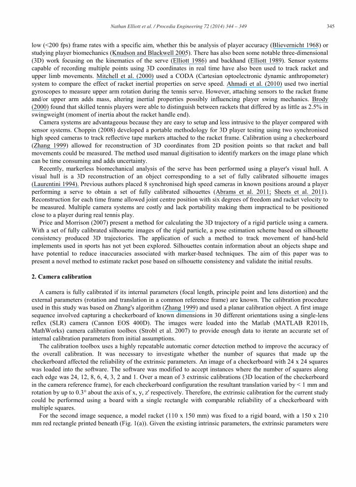
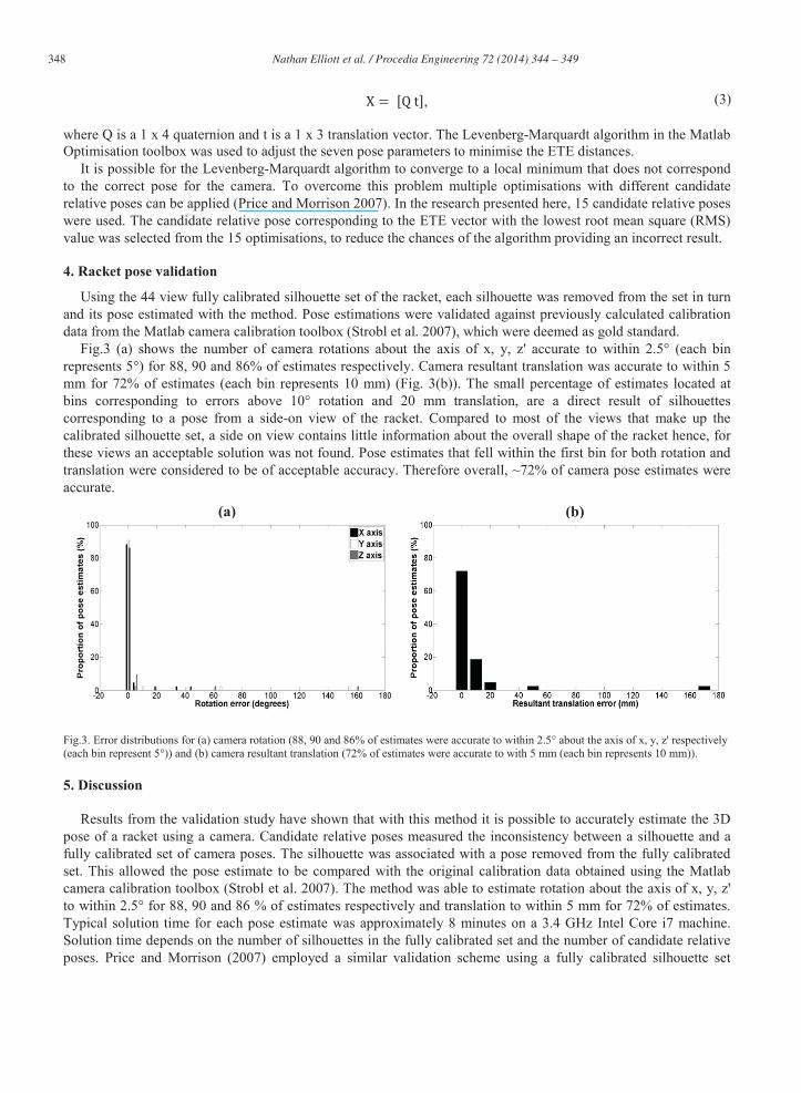
Fig.3 (a) shows the number of camera rotations about the axis of x, y, z' accurate to within 2.5° (each bin
represents 5°) for 88, 90 and 86% of estimates respectively. Camera resultant translation was accurate to within 5
mm for 72% of estimates (each bin represents 10 mm) (Fig. 3(b)). The small percentage of estimates located at
bins corresponding to errors above 10° rotation and 20 mm translation, are a direct result of silhouettes
corresponding to a pose from a side-on view of the racket. Compared to most of the views that make up the
calibrated silhouette set, a side on view contains little information about the overall shape of the racket hence, for
these views an acceptable solution was not found. Pose estimates that fell within the first bin for both rotation and
translation were considered to be of acceptable accuracy. Therefore overall, ~72% of camera pose estimates were
accurate.
Fig.3. Error distributions for (a) camera rotation (88, 90 and 86% of estimates were accurate to within 2.5° about the axis of x, y, z' respectively
(each bin represent 5°)) and (b) camera resultant translation (72% of estimates were accurate to with 5 mm (each bin represents 10 mm)).
5. Discussion
Results from the validation study have shown that with this method it is possible to accurately estimate the 3D
pose of a racket using a camera. Candidate relative poses measured the inconsistency between a silhouette and a
fully calibrated set of camera poses. The silhouette was associated with a pose removed from the fully calibrated
set. This allowed the pose estimate to be compared with the original calibration data obtained using the Matlab
camera calibration toolbox (Strobl et al. 2007). The method was able to estimate rotation about the axis of x, y, z'
to within 2.5° for 88, 90 and 86 % of estimates respectively and translation to within 5 mm for 72% of estimates.
Typical solution time for each pose estimate was approximately 8 minutes on a 3.4 GHz Intel Core i7 machine.
Solution time depends on the number of silhouettes in the fully calibrated set and the number of candidate relative
poses. Price and Morrison (2007) employed a similar validation scheme using a fully calibrated silhouette set
(3)
(a) (b)
349 Nathan Elliott et al. / Procedia Engineering 72 ( 2014 ) 344 – 349
containing 6, 24 and 60 views of an irregular particle. For a total of 540 pose estimates, 88% were accurate to
within 5° which agrees well with the results in this study. Moreover, Price and Morrison (2007) showed that the
accuracy of the method decreases with the number of views in the fully calibrated silhouette set. Price and
Morrison (2007) used the pose estimates to accurately predict trajectories of rigid particles captured using a high
speed video camera. Development of the method to estimate racket trajectories from high speed footage would
provide a novel approach for measuring their movements. The work presented here is the first step to fully validate
a new method capable of measuring racket movements in 3D using a camera. The next step will be to apply the
validation scheme presented in this paper to a full size racket. Thereafter, validate pose estimates associated with
silhouettes which are not originally part of a fully calibrated set and silhouettes associated with high speed video
frames of a moving racket. Ultimately, the method could be used to measure racket movements during actual
tennis strokes using a gold standard motion capture system as a reference for validation.
6. Conclusion
The initial validation of an image based method to estimate the 3D pose of tennis racket has been presented. A
good agreement was found between pose estimates and data obtained using calibration software. The markerless
method has potential to track racket movements without interfering with players strokes. Therefore, it could be
used to inform researchers and manufacturers about racket performance in real play conditions. Since the fully
calibrated silhouette set could be captured in isolation, only one camera would need to be positioned near the court
to capture the racket during live play. Currently, there are no systematic approaches to measure racket performance
in real tennis play. Development of this method is intended to prompt the design of recognised play test protocols.
This will allow parameters such as racket velocity and angle to be measured for typical tennis shots. Moreover,
assist player feedback for coaching purposes and the selection of racket prototypes.
References
Abrams, G. D., Sheets, A. L., Andriacchi, T. P., Safran, M. R., 2011. Review of tennis serve motion analysis and the biomechanics of three
serve types with implications for injury. Sports Biomechanics 10(4), 378-390.
Ahmadi, A., Rowlands, D. D., James, D. A., 2010. Development of inertial and novel marker-based techniques and analysis for upper arm
rotational velocity measurements in tennis. Sports Engineering 12, 179-188. Blievernicht, J.G., 1968. Accuracy in the Tennis Forehand Drive: Cinematographic Analysis. Research Quarterly for Exercise and Sport 39(3),
776-779.
Brody, H. 2000. Player sensitivity to the moments of inertia of a tennis racket. Sports Engineering 3, 145-148. Choppin, S., 2008. Modelling of tennis racket impacts in 3D using elite players. PhD, University of Sheffield.
Elliott, B. C., Marsh, A. P., Blanksby, B., 1986. A Three-Dimensional Cinematographic Analysis of the Tennis Serve. International Journal of
Sport Biomechanics 2(4), 260-271. Elliott, B.C., Marsh, A.P., Overheu, P.R., 1989. The Topspin Backhand Drive in Tennis: A Biomechanical Analysis. Journal of Human
Movement Studies 16, 1-16.
Forbes, K., Voigt, A., Bodika, N., 2003. Using silhouette consistency constraints to build 3D models. In: Proceedings of the Fourteenth Annual Symposium of the Pattern Recognition Association of South Africa (PRASA).
Knudson, D. V., Blackwell, J. R., 2005. Variability of impact kinematics and margin for error in the tennis forehand of advanced players.
Sports Engineering 8, 75-80. Laurentini, A., 1994. The visual hull concept for silhouette-based image understanding. IEEE Transactions on pattern analysis and machine
intelligence 16(2), 150-162.
Mitchell, S. R., Jones, R., King, M., 2000. Head speed vs. racket inertia in the tennis serve. Sports Engineering 3, 99–110. Price, M., Morrison, G., 2007. Validating rigid body simulation of real particle shapes using pose estimation from high speed video. In:
proceedings of the 4th international conference on discrete element methods, Brisbane, Australia.
Sheets, A. L., Abrams, G. D., Corazza, S., Safran, M. R., Andriacchi, T. P., 2011. Kinematics differences between the flat, kick, and slice serves measured using a markerless motion capture method. Annals of biomedical engineering 39(12), 3011-3020.
Strobl, K., Sepp, W., Fuchs, S., Paredes, C., Arbter, K., 2007. Camera Calibration Toolbox for Matlab,
http://www.vision.caltech.edu/bouguetj/calib_doc/ Wong, K. -Y. K., 2001. Structure and motion from silhouettes. PhD, University of Cambridge.
Zhang, Z., 1999. Flexible camera calibration by viewing a plane from unknown orientations. In: proceedings of the 17th international
Conference on Computer VisionCorfu, Greece, pp. 666-673.
Related Documents


![Workshop Tennis Racket[1]](https://static.cupdf.com/doc/110x72/545e390eaf795937758b472d/workshop-tennis-racket1.jpg)