Published Manual Number/ECN: MATOUTWRAE/2007473A • Publishing System: TPAS • Access date: 1/4/2008 • Document ECN's: Latest Available Technical Reference— Mark II, III, IV and V 100 Formula, Single Motor Washer-Extractor PELLERIN MILNOR CORPORATION POST OFFICE BOX 400, KENNER, LOUISIANA 70063-0400, U.S.A.

Welcome message from author
This document is posted to help you gain knowledge. Please leave a comment to let me know what you think about it! Share it to your friends and learn new things together.
Transcript
Published Manual Number/ECN: MATOUTWRAE/2007473A• Publishing System: TPAS• Access date: 1/4/2008• Document ECN's: Latest Available
Technical Reference—
Mark II, III, IV and V100 Formula, Single Motor Washer-Extractor
PELLERIN MILNOR CORPORATION POST OFFICE BOX 400, KENNER, LOUISIANA 70063-0400, U.S.A.
Please Read About the Manual Identifying Information on the Cover—The front cover displays pertinent identifying information for this manual. Most important, are the published manual number (part number) /ECN (date code). Generally, when a replacement manual is furnished, it will have the same published manual number, but the latest available ECN. This provides the user with the latest information applicable to his machine. Similarly all documents comprising the manual will be the latest available as of the date the manual was printed, even though older ECN dates for those documents may be listed in the table of contents. When communicating with the Milnor factory regarding this manual, please also provide the other identifying information shown on the cover, including the publishing system, access date, and whether the document ECN’s are the latest available or exact. Best Available Information—This manual contains the most accurate and complete information available when Milnor shipped your machine/software. Products are occasionally released with the best available documentation, even though the device identification (model numbers, etc.) on the documentation does not explicitly include the delivered model. In such cases, use the documentation provided. Although unlikely, incorrect manuals may have been shipped with your machine. If you believe you received the wrong manuals, or if you need specific information about any aspect of your machine not addressed in the provided documentation, contact the Milnor Customer Service group. References to Yellow Troubleshooting Pages—This manual may contain references to “yellow pages.” Although the pages containing trouble-shooting procedures are no longer printed on yellow paper, troubleshooting instructions, if any, will be contained in the easily located “Troubleshooting” section. See the table of contents. Trademarks of Pellerin Milnor Corporation—The following terms, some of which may be used in this publication, are trademarks of Pellerin Milnor Corporation: CBW® E-P OneTouch® Gear Guardian® Mildata® Milnor® Staph-Guard® E-P Express® E-P Plus® Mentor® Milnet® MultiTrac™ Visionex™
Trademarks of Other Companies—The following terms, some of which may be used in this publication, are trademarks of their respective companies: Acronis® Microsoft Windows 2000® Yaskawa® Siemens® Atlas 2000® Microsoft Office XP® Microsoft Access® Seagate Crystal Reports® IBM® Microsoft Windows NT® Microsoft Windows XP®
Comments and Suggestions Help us to improve this manual by sending your comments to:
Pellerin Milnor Corporation Attn: Technical Publications P. O. Box 400 Kenner, LA 70063-0400 Fax: (504) 469-1849

Table of Contentsfor MATOUTWRAE/2007473A
Mark II, III, IV and V 100 Formula, Single Motor Washer-Extractor
Page Description Document/ECN
1 About This Manual MHTOUTWRAE/2007473A
3 Section 1: Commissioning4 Important Owner/User Information - Machines
with a Keypad BICM3K01/20030620
6 About the User Controls - Machines with a Keypad MSOP0235BE/9836AV
9 Section 2: Programming10 Programming the Mark II, III, IV and V 100 Formula,
Single Motor Washer-Extractor Controller MSOP0266AE/9526FV
39 Section 3: Operating40 Operating Mark II, III, IV and V 100 Formula,
Single Motor Washer-Extractors MSOP0268AE/9530DV
50 Using the Five-Compartment Flushing Supply Injector MSOP0207AE/9516BV
52 Modifying Formulas in Progress MSOP0236BE/9516CV
57 Section 4: Troubleshooting58 100 Formula, Single Motor Washer-Extractor
Error Messages MSTS0210AE/9530CV
63 Monitoring Inputs and Outputs for Mark II and III FxW Washer-Extractors MSOP0267AE/9530DV
68 Monitoring Microprocessor Inputs and Outputs for the Mark IV and V 100 Formula, Single Motor Washer-Extractors MSOP0267BE/9711BV
74 Manual Mode Menu Functions on Mark II, III, IV and V Washer-Extractors MSOP0254BE/9514DV
83 Section 5: Supplemental Information84 Notice About Hardware Sections BMP970004/97071V
85 Hardware Components of Serial Microprocessor Controllers BICMDF01/20050112
94 How to Upgrade Microprocessor EPROM Chips BICMUM01/20040817
102 Memory Download Box Applications BICUDC01/20010807
105 Construction of External Serial Link Cables BICWUC01/20050112
110 Printer Requirements and Settings BICWUI01/20071113
112 How "Chemwait" Works in Milnor Mark I, II, III, IV and V Microprocessor Washer-Extractor Controllers MSSM0248AE/9526BV
113 Adjusting Level Sensing Apparatuses and Setting Levels on 100-Formula Washer-Extractors and Textile Machines MSSM0238BE/9527BV
119 Troubleshooting Basket Speed Errors on Single-motor Washer-extractors BICWUT01/20050127
129 Speed Limiting System on 42032F7S and 36030F8S Open-Pocket Staph-Guard Models BICWPF02/20020214
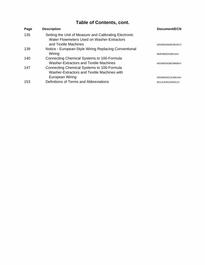
Table of Contents, cont.Page Description Document/ECN
135 Setting the Unit of Measure and Calibrating Electronic Water Flowmeters Used on Washer-Extractors and Textile Machines MSSM0269AE/9525CV
139 Notice - European-Style Wiring Replacing Conventional Wiring BMP980025/9814AV
140 Connecting Chemical Systems to 100-Formula Washer-Extractors and Textile Machines MSSM0262BE/9808AV
147 Connecting Chemical Systems to 100-Formula Washer-Extractors and Textile Machines with European Wiring MSSM0262CE/9814AV
153 Definitions of Terms and Abbreviations BIUUUK05/20050112
MHTOUTWRAE/2007473A (1 of 1)
ABOUT THIS MANUAL Scope—This reference manual provides commissioning, programming, operating, and troubleshooting information for the Milnor Mark II, III, IV, and V 100 formula, single motor washer-extractor controllers. See the installation manual for information on machine installation procedures and mechanical requirements. See the service manual for preventive maintenance, service procedures, and mechanical parts identification. See the schematic manual for electrical parts identification and electrical troubleshooting. Normal Display Sequence at Each Power Up—Verify that the messages appearing on the display at start up are as shown in “OPERATING THE MARK II, III, IV, AND V 100 FORMULA, SINGLE MOTOR WASHER-EXTRACTORS.” (see Table of Contents). Any other message(s) indicate an error condition that must be corrected before the machine will operate. See “100 FORMULA, SINGLE MOTOR WASHER-EXTRACTOR ERROR MESSAGES.” Manual Number/Date Code (When To Discard or Save)—The manual number/date code is located on the inside front cover, upper right corner just above the manual name. Whenever the manual is reprinted with new information, part of this number changes. If the date code after the “/” changes, the new version applies to all machines covered by the old version, but is improved— thus the old version can be discarded. If the manual number before the “/” changes, the new manual covers only new machines. Example: Discard MATMODELAE/8739CV when MATMODELAE/8739DV is received (minor improvements). Also, discard MATMODELAE/8739DV when MATMODELAE/8746AV is received (major improvements). But keep MATMODELAE/8746FV when MATMODELBE/8815AV is received, since the new manual no longer applies to machines originally shipped with the old manual. Documents and Change Bars—The individual documents comprising this manual use the same revision criteria as the manual. Text documents also display change bars. Example: When sectionMSOP0599AE/9135BV becomes MSOP0599AE/9135CV, change bars with the letter “C” appear next to all changes for this revision. For a major rewrite (e.g., MSOP0599AE/9226AV), all change bars are deleted. For Assistance—Please call: Pellerin Milnor Corporation Phone:(504) 467-9591 Attn: Service Department Fax:(504) 467-9777 P. O. Box 400 Kenner, LA 70063-0400


Section 1Commissioning

PELLERIN MILNOR CORPORATION
BICM3K01 (Published) Book specs- Dates: 20030620 / 20030620 / 20030620 Lang: ENG01 Applic: CM3
Important Owner/User Information—Machines with a KeypadTake the following important steps before placing this machine in operation:1. Ensure safety of laundry personnel.2. Protect against data loss.3. Customize data (configure, formula, and productivity data).
1. Ensure Safety of Laundry PersonnelEnsure that all personnel who will operate or maintain this machine read the safety manualbefore permitting them access to the machine. Ensure that all user manuals are available to theappropriate personnel and that all precautions explained in the safety and other user manuals areobserved.
2. Protect Against Data LossFollow the safeguards listed below to protect against data loss caused by human tampering,electromagnetic interference (EMI), physical damage to the data storage medium, or loss ofpower to random access memory (RAM).1. Keep the Run/Program keyswitch set to run (R) and secure the keys. Users must
understand proper use of this control. See "ABOUT THE USER CONTROLS. . ." (see Tableof Contents).
2. Keep all electric box doors closed and locked. Secure the keys.3. Leave machine power on for 48 hours before customizing data. This fully charges the
microprocessor battery, which will then supply power to the RAM for 90 days even ifmachine power is off.
4. Replace the battery board every five years. A capacitor on the processor board can supplypower to the RAM for several hours with the battery removed.
5. Keep electronic back-up data and/or a printed record of all field-programmed data (e.g., washformulas, configure values, step names, chemical names) in case of data loss. See theinstructions for downloading and printing this data if the machine has this capability.
6. For machines that accumulate productivity data (e.g., count of loads processed), transcribeany needed data frequently, as described in the instructions for data accumulation.
3. Customize Data
3.1. When to Customize Data• When commissioning the machine• When restoring a machine to service after a lengthy shutdown• When required by error message• After replacing the CPU board• After upgrading software (replacing EPROMs)• After adding or removing optional equipment
3.2. What Customizing Requires—Verify configuration. Program formulas and clearproductivity data, if applicable. See the programming and operating sections in this manual forinstructions.

Important Owner/User Information—Machines with a Keypad
PELLERIN MILNOR CORPORATION
3.3. Data Accessibility—Configure and formula data can only be altered while the keyswitch isin the program position (data is keyswitch-protected). Producitvity data, because it isaccumulated in the run mode, cannot be keyswitch-protected and is accessible to anyone. Data isaccessible to the extent described in the following table:
Table 1: Data Type and AccessibilityWays Data Can BeUsed and Altered
Data can be readData can be over-written
Data can be up/downloadedData can be cleared
Type of Data Machines Data Applies To Contents after clearingdryer (includes gains) Yes Yes Yes Yes example valuesshuttle, single-stage press Yes Yes No Yes zerostwo-stage press, Cobuc, LinearCosto, discharge sequencer
Yes Yes No No n.a.
Configure Data
washer (and textile)-extractor,centrifugal extractor
Yes Yes Yes No n.a
step, chemicalnames
washer (and textile)-extractor Yes Yes Yes Yes example valuesFormula Data
formulas washer (and textile)-extractor,centrifugal extractor, dryer
Yes Yes Yes Yes empty
Productivity Data washer (and textile)-extractor,centrifugal extractor, dryer
Yes No No Yes empty
3.4. If Data Becomes Corrupt—If the microprocessor senses that data is unusable or unreliable,an error message will appear (usually at power-up), possibly preventing machine operation. Theconsequences and appropriate actions for each error message are explained in the troubleshootinginstructions. Follow these instructions exactly to ensure that corrupt data is completelyeliminated and replaced with valid data. Failure to do so may result in unsafe operation ormachine damage.
— End of BICM3K01 —

MSOP0235BE/9836AV (1 of 3)
ÈABOUT THE USER CONTROLS—MACHINES WITH A KEYPAD
User controls are of two types—electro-mechanical controls (switches, buttons, and status lights) and micro-processor interface controls (display, keypad, keyswitch, and printer/download connection). Controls are mountedon one or more nameplates on the machine or a separate electric box.
NOTE: Do not attempt to use your machine merely by referring to the descriptions of controls. Readthe operating, programming, and troubleshooting instructions throughout this and the operator man-ual.
ÊElectro-Mechanical ControlsElectro-mechanical controls vary with machine model and are explained in the machine-specific operator
manual furnished with the machine.

ÏExample Key Symbols Used in the TextSymbology What It Means
, Turn the keyswitch clockwise to program ( ), then press and release the Enter/Next key.
, Turn the keyswitch counterclockwise to run ( ), then press and release the Enter/Next key.
Press and release the key shown.
/ A slash between symbols means use either key shown. The up and down arrow keys are often shownthis way (i.e., scroll up or down the menu choices).
, , ,, , ,
Typical example of a word entry (spells out “POLY”). In word (alphanumeric) data fields, pressthe up or down arrow key to move right or left to the next character position. Press each key until
the desired character appears (e.g., press until “P” appears). A comma between symbols meanspress and release each key sequentially.
, , Typical example of a number entry (enters the value 155). In numeric data fields, the cursorautomatically advances to the next character position when each numeral is entered.
+ + A “ + ” between symbols means press and hold each key in the order shown until all keys aredepressed at the same time, then release all keys.
hold + Key(s) must be held depressed for the intended action to occur. Action will stop when key(s) is (are)released.
<xx><response><password>
This is an alternative way of depicting word and number entries when the exact values are determined bythe user. <xx> means enter a two digit number. <response> means enter the value prompted for by thedisplay. <password> means enter the password (or numeric passcode).
Press and release the Stop button ( ).
Press and release the Start button ( ).
ÎFIGURE 1 (MSOP0235BE)
ÎMicroprocessor Interface Controls and Example Key Symbols
B
B
ABOUT THE USER CONTROLS—MACHINES WITH A KEYPAD MSOP0235BE/9836AV (2 of 3)

ÊMicroprocessor Interface ControlsThese controls, shown in FIGURE 1, include the keyswitch, display, and keypad, located on the main name-
plate (position on nameplate varies), and the printer/download connection, located on its own nameplate. Thesecontrols permit the user to pass data to and from the microprocessor controller.
NOTE: This section folds out so that you may continue to refer to FIGURE 1 as you review the remainderof this manual.
ËKeyswitch —This key-operated switch provides security for all field-programmed data in memory. With the
keyswitch set to run ( ), this data cannot be changed. The key cannot be removed in the program ( ) position.
DATA LOSS HAZARD—Improper use of the keyswitch may corrupt programdata.
☞ Return to the run mode only when the display says Ok Tur n Key to Run .
☞ Only power off or on with the keyswi tch at run.
☞ Do not leave the key accessible to unauthorized personnel.
ËDisplay —This two- or four-line device displays messages and data entry screens. Messages inform the user asto the machine’s operating status or alert the user to conditions that must be satisfied before operation can continue.Message displays in this manual are normally black.
Data entry screens prompt the user to enter data at the keypad. As keys are pressed, the data appears in thedata input field on the display. A blinking cursor always shows where the next character will be entered. Data inputscreens in this manual are gray, the data input field is black, and the starting cursor position is underlined.
ËKeypad —The 12- or 30-key keypad is used for programming, making selections (e.g., selecting formulas in awasher-extractor), responding to display messages, certain normal operating procedures, and manual operation.Applicable procedures are explained in the remainder of this manual and depicted using symbols to indicate pressingkeys on the keypad. These symbols are explained in the “Example Key Symbols Used in the Text” in FIGURE 1.Keep FIGURE 1 folded out when reviewing procedures elsewhere in the manual that require the keypad.
NOTE: Some keys on the 30-key keypad are not used on some machines.
ËPrinter/Download Connection (if so equipped) —Connect a Milnor®-supplied printer here to printfield-programmed data (e.g., formulas) and accumulated data (e.g., count of loads processed), if applicable. Connecta Milnor®-supplied serial downloader here or interconnect between machines to copy field-programmed data be-tween devices. Printing and downloading, if applicable, are explained elsewhere in this manual.
ABOUT THE USER CONTROLS—MACHINES WITH A KEYPAD MSOP0235BE/9836AV (3 of 3)

Section 2Programming
MSOP0266AE/9526FV (1 of 28)
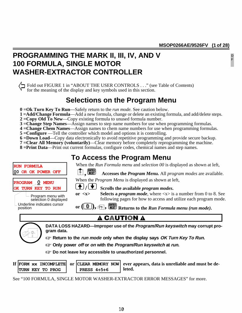
ÈPROGRAMMING THE MARK II, III, IV, AND V100 FORMULA, SINGLE MOTORWASHER-EXTRACTOR CONTROLLER
Fold out FIGURE 1 in “ABOUT THE USER CONTROLS . . .” (see Table of Contents) for the meaning of the display and key symbols used in this section.
ÊSelections on the Program Menu0 =Ok Turn Key To Run—Safely return to the run mode. See caution below.1 =Add/Change Formula—Add a new formula, change or delete an existing formula, and add/delete steps.2 =Copy Old To New—Copy existing formula to unused formula number.3 =Change Step Names—Assign names to step name numbers for use when programming formulas.4 =Change Chem Names—Assign names to chem name numbers for use when programming formulas.5 =Configure —Tell the controller which model and options it is controlling.6 =Down Load—Copy data electronically to avoid repetitive programming and provide secure backup.7 =Clear All Memory (voluntarily) —Clear memory before completely reprogramming the machine.8 =Print Data—Print out current formulas, configure codes, chemical names and step names.
ÊTo Access the Program MenuRUN FORMULA 00 OR OK POWER OFF
When the Run Formula menu and selection 00 is displayed as shown at left,
, Accesses the Program Menu. All program modes are available.When the Program Menu is displayed as shown at left,
/ Scrolls the available program modes.or <x> Selects a program mode, where <x> is a number from 0 to 8. See
following pages for how to access and utilize each program mode.
or ( ), , Returns to the Run Formula menu (run mode).
DATA LOSS HAZARD—Improper use of the Program/Run keysw itch may corrupt pro-gram data.
☞ Return to the run m ode only when the display says OK Turn K ey To Run.
☞ Only power off or on with the Progra m/Run ke yswitch at run .
☞ Do not leave key accessible to unauthorized personnel.
If FORM xx INCOMPLETETURN KEY TO PROG
or CLEAR MEMORY NOW PRESS 4+5+6
ever appears, data is unreliable and must be de-leted.
See “100 FORMULA, SINGLE MOTOR WASHER-EXTRACTOR ERROR MESSAGES” for more.
DF
PROGRAM 0 MENUOK TURN KEY TO RUN
Program menu with selection 0 displayed
Underline indicates cursor position

Ê1 = ADD/CHANGE FORMULAAt the start of formula programming, the controller prompts for a formula number and formula name. At the
start of each step (e.g., flush, break, intermediate extract), the controller prompts for a step name and pauses topermit deleting or duplicating the step. Once in a formula, you may move around to specific data and use the helpscreens. You may end the formula with a bath or an extract. You may abort a new formula or delete an existingformula. When you end a formula, the controller prompts for type of rotation to end with. Formulas 01 through 98are available for programming.
NOTE: Two non-programmable formulas are also furnished—formula 00, used to commission a new machine(see “RUNNING . . .”) and formula 99, used to develop new formulas (see “MODIFYING FORMULAS . . .”).
PROGRAM 1 MENU ADD/CHANGE FORMULA
When the Program Menu and mode 1, Add/Change Formula is displayed,
Accesses mode 1 and prompts for a formula number.
ËTo Select a Formula NumberWith the cursor at formula number as shown at left,
/ Scrolls the unused formula numbers.
+ / + Scrolls the existing formulas.
Accesses the selected formula. Cursor goes to formula name field.
or Aborts formula programming and returns to Program Menu.
ËTo Name or Rename a Formula —Every formula initially has the default formula name “FORMULAxx” where xx is the formula number. This may be overwritten with any name up to 16 characters.
With the cursor in the formula name field, as shown at left,
/ Moves the cursor right/left within the formula name field.
<x> Enters a character at the cursor where <x> is any letter, num-ber, or symbol on the alphanumeric keypad. Press key one or moretimes until desired character appears.
Accepts formula name and prompts for first step name.
ËTo Select a Step Name —Step names are selected by number from the 16 pre-named step names available(see 3= CHANGE STEP NAMES). The default is 00 which names the step “STEPxx,” where xx is the step number.With the cursor at the step name number, as shown at left,
/ Scrolls the step names.
<xx> Enters a step name by number, where <xx> is a number from 00 to 15.
Accepts selected step name. Page A of this step appears with nocursor to permit deleting or duplicating this step, if desired.
or Only if this is step 1, returns to formula name.
ADD/CHANGE FORMULAADD/CHANGE FORMULA
05 FORMULA 05
Formula nameFormula number
“ADD” or “CHANGE” blinksfor unused or existing for-
F05 FORMULA 05F05 SHEETSS01
Default formula nameFormula name field(Any name up to 16 characters may be entered)
PROGRAMMING THE MARK II, III, IV, & V 100 FORMULA, SINGLE MOTOR WASHER-EXTRACTOR CONTROLLER MSOP0266AE/9526FV (2 of 28)

ËTo Delete or Duplicate a StepF05 TMMQFFFHC3WLL SS01
When page A, shown at left, first appears with no blinking cursor, the current stepmay be deleted or duplicated.
+ Deletes this step. The next higher step becomes the current step. The controller prevents delet-ing an End Formula or a bath between two extracts. To delete an entire formula, see “To Aborta New Formula in Step 1 or Delete an Existing Formula” in this section.
or + Duplicates this step. If this is step 1, the duplicated step becomes the new step 1 and all follow-ing steps move one number higher. Controller prevents duplicating an End Formula or an extract.
or Advances to T (Type of Step) without deleting or duplicating this step.
ËTo Move Around in the Steps and Use the Help Screens —Each step has a step name screenand three data pages (pages A, B, and C). Each data page has several decisions (e.g., duration, bath temperature,chemicals) represented by letters on pages A, B, and C. Move around among steps, screens, pages, and decisions asshown in FIGURE 1, below. See “The Step Decisions” in this section for a full explanation of each step decision.
Scrolls the steps from anywhere in formula programming except PAGE A withno cursor, a chemical group, or decision E. Display returns to the step namescreen for the selected step or to the formula name screen from step 1.
Step NameScreen
Page AWith No Cursor
Data Pages
See "To Select aStep Name" inthis section.
See " ToDelete orDuplicate aStep" in thissection.
Scrolls forward/backward through each validdecision. NOTE:Will not scroll backward out ofa chemical group. Must scroll forward out oflast chemical group, then backward to PAGE A.
Enters a value and advances cursor to next de-cision, where <x> is a valid one to four digit value.
Formula Help Screens
Page A
Each decision in Pages A and Bhas a help screen. When one isdisplayed,
scrolls the valid values.
<x>
(See "The Step Decisions" in this section)
etc.etc. etc. etc.
Chemical group (repeatsfor each chemical)
+ +
Page B
Decision letters shadedgray are those that varywith configuration or onlyappear if configured.
Help screenappears ifno validentry in8 seconds
= delay1 minute
= appearimmediately
= acceptsvalue andadvances
ÎFIGURE 1 (MSOP0266AE)
ÎHow To Move Around In a Formula and Use the Help Screens
PROGRAMMING THE MARK II, III, IV, & V 100 FORMULA, SINGLE MOTOR WASHER-EXTRACTOR CONTROLLER MSOP0266AE/9526FV (3 of 28)

ËTo End a FormulaWithout a Final Extract(Following a Bath)
ËTo End a Formula With a Final Extract Ë
To Abort a New Formulain Step 1 or Delete anExisting Formula
F05 TMMQCCCHC3WLL SF05 T TYPE OF STEPS06 0 END FORMULA
Page A Page BF05 TMMQCC RPMDRC
S066050 ----0--
F05 TMMQCCCHC3WLL SF05 T TYPE OF STEPS01 0 END FORMULA
or Commands EndFormula and prompts:
<T> Commands one of threetypes of final extract,where <T> is 4, 6, or 7,and prompts for a duration(MMQ). See “The StepDecisions.”
( ), Commands End Formula at step 1 and prompts:
END FORMULA #05 ? 0 NO [1=YES]
DELETE FORMULA #05? 0 NO [1=YES]
, Confirms ending theformula and promptsHow to End?or
( ), Cancels ending theformula and returnsto Type of Step.
<MMQ> Commands a duration where<MMQ> is a 3-digit num-ber and prompts for a drain destination if applicable.
<R> Commands a drain destin-ation, where <R> is 0 or 1and prompts or How to End?
, Confirms deleting the formula and returnsto the Program Menu.or
( ), Cancels deleting theformula and returnsto Type of Step.
After confirmation, the ProgramMenu reappears.
NOTE: Whether ending with or without a final extract, decisions continue as explained below.
**PLEASE WAIT**PROGRAM 0 MENU OK TURN KEY TO RUN
ËTo Specify Cylinder Rotation at End of Formula (How To End) —When a formula ends with-out a final extract, selections 0, 1, and 2, explained below are available. When the formula ends with a final extract,all of the following selections are available:
F05 XXX YY Y EF05 HOW TO END? E S06 STOPPED 0 Operator presses or to silence the signal.
REVERSING 1 (at wash speed)–Operator press or to end. DRAIN SPEED 2 Operator presses or to end.BREAK CAKE 3 Cylinder sequences through various motions for three minutes, then stops. Use to
loosen goods that remain plastered to the cylinder after the formula ends. Operatorpresses or to silence the signal.
TUMBLING 4 Like reversing except permits operator to press (to stop cylinder), open door, pulldown any plastered goods, close door, and press (to continue tumbling).
Scroll to step 1, page A, decisionT. when display is as shown be-
With the cursor at page A, deci-sion T (as shown below),
With the cursor at page A, decisionT of the final extract (as shown be-
PROGRAMMING THE MARK II, III, IV, & V 100 FORMULA, SINGLE MOTOR WASHER-EXTRACTOR CONTROLLER MSOP0266AE/9526FV (4 of 28)

/ Scrolls the valid choices.
<x> Enters a valid choice. <x> is 0, 1, or 2 when following a final bath step. <x> is 0, 1, 2, 3, or 4 for a final extract.
Accepts the selected choice. This ends programming for this formula.
**PLEASE WAIT**PROGRAM 0 MENUOK TURN KEY TO RUN Program Menu reappears.
ÊThe Step DecisionsAs shown in FIGURE 2, several programming decisions on pages A and B vary with configuration. For
example, bath temperature may be configured for Fahrenheit (FFF) or Centigrade (CCC) units and Third Water (3)only appears if enabled. Most decisions following Type of Step (T) only apply to bath steps, not extract steps.Applicable step decisions repeat for each step.
Up to 98 formulas with a total of 499 steps may be programmed.
Bath TemperatureStep Duration
Type of Step
3. Dashes appear if decision does not apply.
Water ValvesFill from Tank
LiquorLevel
SteamInjection
Chemicals CylinderSpeed
RotationCycle
How toEnd
Drain/fill On-
TimeOff-
Time
(occursonce performula)
Drain ToRecirculation
Page A Page B Page CF05 F05 F05 XXX YYY ET H
HC CCNN
22C
CC
3
3W S D R CWSSS RPML LMMQ
FFFCCC
H=
hot
C=
cold
C=
cold
2=
2nd
3=3r
d
1. Decision is identified by an abbreviation on the top line. Current value appears on bottom line.2. All decisions apply to bath steps; only underlined decisions apply to extract steps.
Variations based on configuration
Che
m N
umbe
r
Che
m N
ame
Whe
n to
Inje
ct
Dur
atio
n of
Inje
ctio
n
Sig
nal W
ith
+S01 1 0 2 1 7 1 S01 01 02 0 040 0 0 4 0 1 0 1 S01 005 002 0
Notes:Formula and step #
Wash/extract
Flow Control
ÎFIGURE 2 (MSOP0266AE)
ÎThe Step Decisions at a Glance
PROGRAMMING THE MARK II, III, IV, & V 100 FORMULA, SINGLE MOTOR WASHER-EXTRACTOR CONTROLLER MSOP0266AE/9526FV (5 of 28)

ËType of Step: Types of Baths and Extracts Available —End Formula, three types of bath step,
F05 TMMQFFFHC3WLL SF05 T TYPE OF STEPS01 0 END FORMULA
and four types of extract step are available. The control prevents an extract as step 01or step 02 if step 01 is a no water bath. It also prevents two successive extract steps.See “To End a Formula Without a Final Extract. . .,” and “To Abort a New For-mula in Step 1 or Delete an Existing Formula” in this section.
1 1-WAY WASH Increases mechanical action and saves energy. Use for small pieces which cannot tangle.2 2-WAY WASH Reverses cylinder. Use for sheets or other large pieces which tangle unless cylinder
reverses.3 SOAK WASH Cylinder does not turn. Use for delicate fabrics and overnight bath soak (see below).4 PRE+FIN EXT (pre+final extract)
Performs motions toward cycle end to loosen plastered goods. Minimum time =180seconds. Machine extracts for 90 seconds, then the timer stops while the cylinderstops, jogs, and redistributes. Then machine extracts (with a 90-second low speedextract before accelerating to E2 if the machine has E1 and E2) for the remainingcommanded extract time. Use only for goods that tend to plaster, as this functionmay cause unwanted extract recycles.
5 INT EXTRACT (intermediate extract)
For extracts between baths and for final extract at low (E1) speed if machine isequipped with two-speed extract.
6 FINAL EX T E1 duration dictated by configure decision G then E2 for remainder of com-manded extract time.
7 DOUBLE EXT Purges trapped water from goods. Minimum time = 180 seconds. Machine extractsfor 90 seconds. Timer stops as cylinder slows and runs at drain speed for 30 sec-onds then re-enters extract for remaining commanded time. Use for mats.
ËType of Step: Using Soak Wash To Create an Overnight Bath Soak Formula —To cre-ate an overnight bath soak formula, for step 1, command Type of step (T)=3 (Soak Wash), duration of step(MMQ)=600 (one hour), and drain type (D)=2 (Do Not Drain). Then command the temperature, water valves, andlevel desired. For Step 2, accept End Formula to exit, then return to the formula and duplicate step 1 as many timesas hours of soak are desired. See “To Delete or Duplicate a Step” in this section. Modify the formula to add chemi-cals and/or perform other functions where desired. Take care to delete any unnecessarily duplicated functions fromsteps. Power, air pressure, and steam (if used) must remain on as long as this formula is running.
ËDuration of StepF05 T MMQFFFHC3WLL SF05 MMQ BATH TIMES01 001 = 00.25 MIN
MMQ indicates minutes (MM) and quarter minutes (Q).
0 minutes and 15 seconds (minimum)
010 = 01.00 MI N 1 minute (default)113 = 11.75 MI N 11 minutes and 45 seconds (example)633 = 63.75 MI N 63 minutes and 45 seconds (maximum)
PROGRAMMING THE MARK II, III, IV, & V 100 FORMULA, SINGLE MOTOR WASHER-EXTRACTOR CONTROLLER MSOP0266AE/9526FV (6 of 28)

ËBath Temperature —Appears if temp probes enabled (configure decision T). Accessible if this
F05 TMMQFFFHC3WLL S F05 FFF S01 000 TEMP oF
is a bath step (other than a no water bath). FFF(Fahernheit) or CCC(Centigrade)appears per configure decision A. If a temperature is commanded, thermo-modulationor steaming is required; otherwise, the cursor returns here for temperature correction.
000 TEMP oF No temperature requirement for this bath. Value displayed reverts to “---.” 050 TEMP oF = 50° F. 010 T EMP oC = 10° C (default and minimum, if 000 not commanded) 205 TEMP oF = 205° F. 095 T EMP oC = 95° C (maximum).
ËWater Valves: Available Valves and Ways To Control Them —Configure decision K deter-mines which of the four combinations of water valves shown below is displayed. Valves are accessible if this is abath step. The water valve(s) will function as commanded here either 1) at the start of fill, if tank fill is not com-manded for this bath (see “Water Valves: Fill From Tank” in this section), or 2) when the tank valve closes, if levelis not yet achieved.
hot and col d or cold and 2nd or hot, cold , and 3rd or col d, 2nd, and 3rd
Each water valve is a separate
F05 TMMQCCCHC3WLL S
S01
decision. 3rd water appearsonly if enabled. Unless statedotherwise, all selections applyto each valve.
F05 TMMQCCCC23WLL SS01
OFF 0 Off for this bath OFF 0 Off for this bathON 1 On during fill ON 1 On during fill
↑oC(or↑oF) 2 On during fill if actual temp- No other selections are available. erature is below commanded (raises temp). Not available for cold water valve.
↓oC(or↓oF) 3 On during fill if actual temp- erature is above commanded (lowers temp). Not available for hot water valve.
Example: Example: F05 TMMQCCCHC3WLL SS01 110
Split hot/cold
F05 TMMQCCCC23WLL SS01 11 0 Split cold/2nd
001 3rd only 001 3rd only
coldhot 3rd
2ndcold 3rd
PROGRAMMING THE MARK II, III, IV, & V 100 FORMULA, SINGLE MOTOR WASHER-EXTRACTOR CONTROLLER MSOP0266AE/9526FV (7 of 28)

ËWater Valves: Regulating Incoming Water Temperature With Thermo-ModulationAccessible if hot water valve enabled (configure decision K). Thermo-modulation regulates incoming water tempera-ture by turning the water valve(s) on and off during fill to maintain commanded temperature. When programming, itis helpful to know the split water temperature (temperature achieved by opening hot and cold simultaneously).
F05 TMMQCCCHC3WLL SS01 230 Hot and cold both modulate. Use this method when desired temperature is near
split or when split water temperature is unknown or varies significantly.130 Hot=on, cold =modulates. This provides a faster more accurate fill (fewer tempera-
ture swings) when the commanded temperature is known to be hotter than split.210 Hot=modulates, cold=on. This provides a faster more accurate fill (fewer tempera-
ture swings) when the commanded temperature is known to be colder than split.
NOTE 1: If desired, modulate hot and 3rd when 3rd is cold water, or cold and 3rd when 3rd is hot water.NOTE 2: Modulation controls the average temperature of the incoming water. Bath temperature may varydue to inconsistant incoming water temperature/pressure and because it is influenced by the temperature ofthe preceding bath.
ËWater Valves: Fill From Tank —Accessible if this is a bath step. If tank fill is called for in this bath, the tankvalve opens until either 1) level is achieved, or 2) the time specified in configure decision I (fill error ) expires, afterwhich, the water valve(s) continue filling to the commanded level.
F05 TMMQCCCHC3WLL SS01 0 Do not fill from tank.
1 Fill from tank.
ËWater Valves: Lowering Bath Temperature with Cooldown —A bath with cooldown consistsof two bath steps with no drain between them. In the second step, specify the desired cooler temperature, all watervalves off, and any bath level. The controller will automatically insert a one minute duration (MMQ=010) in thecurrent step and Do Not Drain (D=2) in the former step. The cooldown temperature must always be 15°-20°F(8°-11°C) higher than the hottest ambient temperature or cold water temperature that will be encountered,or it may take a long time or be impossible to achieve the commanded cooldown temperature. Commandingno water (all water valves off) in a step following an extract or in a machine with no cooldown (configure decisionJ), will result in the error:
F05 COOLDOWN ILLEGALS01 PRESS NEXT
If the display at left appears,
returns the cursor to the first water valve decision.
PROGRAMMING THE MARK II, III, IV, & V 100 FORMULA, SINGLE MOTOR WASHER-EXTRACTOR CONTROLLER MSOP0266AE/9526FV (8 of 28)

ËLiquor Level: Specifying Inches or Centimeters (Electronic Level Sensing)F05 TMMQFFFHC3WLL S F05 LEVE L LL S02 00
Accessible if this is a bath step. Units are inches or centimeters as specified in con-figure decision A. Value is two digits.No water
<xx > Minimum level for a bath not preceding an extract, where <xx> is the value speci-fied in the Low Level configure decision .
<yy > Minimum level for a bath preceding an extract, where <yy> is the value specifiedin the Med Level configure decision. If a value lower than <yy> is entered and anextract is programmed for the next step, the controller will automatically replacethis lower value with <yy>.
<zz > Maximum level for any bath, where <zz> is the value specified in the High Levelconfigure decision.
17 17 inches (or centimeters)—example.
ËSteam Injection and How To Select the Steam Code —Steam enabled (configure decision H).Accessible if this is a bath step . No steam and six steaming choices are available. Each steaming choice specifiesthe value shown in the list of choices below left, for each of three conditions (early, after, and timer) explained inthe box below right.
F05 TMMQFFFHC3WLL S EARLY AFTER TIMER S NO STEAM 0
NO YES RUNS 1
NO NO STOPS 2
NO YES STOPS 3
YES YES RUNS 4
YES NO STOPS 5
YES YES STOPS 6
Early: Yes starts steaming at lowest level. Use yes when machine has onlycold water valve or when plant has only low-temperature hot water. No startssteaming when commanded level achieved. Use no when machine has both hot andcold water valves if commanded temperature is lower than hot water temperature.
After: Yes resumes steam in this bath if temperature falls below commanded,once initially achieved. No prohibits further steam once temperature is achieved.Use no if chemicals or goods may be harmed by steam after chemical injection (asin bleach baths), otherwise use yes.
Timer: Runs while steaming or stops until temperature first achieved. Useruns if temperature need not be exactly maintained throughout bath and/or whenit is certain that commanded temperature will be nearly achieved while filling. Usestops if temperature must be achieved before adding chemicals; otherwise, soft-ware will suppress this chemical-add choice.
PROGRAMMING THE MARK II, III, IV, & V 100 FORMULA, SINGLE MOTOR WASHER-EXTRACTOR CONTROLLER MSOP0266AE/9526FV (9 of 28)

ËChemicals: Applicable Decisions —Chemical decisions are only accessible if this is a bath step, but anynumber of available chemicals can be commanded in the same bath. The available chemicals are those enabled inthe # of Chem Valves configure decision. For each chemical desired, the control repeats the chemical decisions
highlighted at left, including chemical number (CC), chemical name (NN), when tostart injection (W), duration of injection (SSS), and signal with chemical (*). Ifchemical number 16 (signal only) is selected, the control skips SSS and * . If optional
chemwait (chemsave) is functioning on this machine when a chemical injection is called for, the machine timer willstop in response to a wait signal from the chemical system. See “HOW CHEMWAIT WORKS.”
ËThis Chemical: Number ( CC) and Name ( NN)F05 CCNNWSSS*RPMDRC CCNN CHEM# AND NAME 0000 NO CHEMICAL
Although chemical number and chemical name are separate decisions, they sharethe same help screen.No chemicals (or no additional chemicals) in this bath (default). Skips SSS and * .
0200 CHEMICAL 02 Chemical 02 (example). Cursor advances to NN from any valid chemical number. xx 00 ILLEGAL CHEM An invalid value was entered, where xx is a number outside the range specified in
the # of Chemical Valves configure decision. Cursor remains at CC for correction. 1600 CHEMICAL 16 Operator signal sounds without chemical being injected. Cursor advances to NN,
then W, but skips SSS and *. Operator must cancel signal to resume operation. 0100 CHEMICAL 01 Names chemical 01 (example) by chemical number (default). 0301 ALKALI Gives chemical 03 the name Alkali (which was previously assigned to chemical
name 01) (example). See “4= Change Chem Names” in this section.
In the help screen, accepts the chemical number and name. The cursor advances to W for a validchemical or to the next decision following the chemical decisions for chemical 00 (no chemical).
ËThis Chemical: When To Start InjectionF05 CCNNWSSS*RPMDRC F05 W WHEN START S01 0 WITH FILL
Use this decision to ensure that chemicals are injected into the bath safely (e.g., ac-ceptable concentrations and bath temperatures). To avoid injecting two or morechemicals simultaneously, use Do Not Drain (programming decision D=draintype) to combine two or more bath steps into one bath, with one injection in each.
0 WITH FIL L As the machine is filling. 1 LEVEL O K When level is satisfied. 2 LEV+ oC OK or 2 LEV+ oF OK - When level and temperature are both satisfied (only available
when steaming to a specified temperature with timer stops while steaming is com-manded).
ËThis Chemical: Duration of Injection (in seconds)F05 CCNNWSSS*RPMDRC F05 SSS CHEM ADD 001 SECS One second (minimum and default). CHEM ADD 127 SECS 127 seconds (maximum). This value automatically inserted if any higher value en-
tered.
F05 CCNNWSSS*RPMDRC S01
PROGRAMMING THE MARK II, III, IV, & V 100 FORMULA, SINGLE MOTOR WASHER-EXTRACTOR CONTROLLER MSOP0266AE/9526FV (10 of 28)

ËThis Chemical: Signal With ChemicalF05 CCNNWSSS* RPMDRC F05 SIGNAL? * S01 NO 0
The signal occurs at the time specified by the when to start injection decision. Thecommanded injection will not start until the signal is cancelled by the operator.
S01 YES 1
ËCylinder Speed —Accessible if this is not a soak wash (see “Type of Step . . .” in this section). Wash andextract speeds are programmable. Value is percent of normal. During bath steps, the cylinder will rotate at the speedcommanded here, during the on-time commanded below (see “Cylinder Rotation On-Time . . .” in this section).
F05 CCNNWSSS*RPMDRC F01 SPEED RPM S01 WASH 015 15 RPMs wash speed (example)
WASH 005 5 RPMs—Minimum allowable wash speed WASH 040 40 RPMs—Maximum allowable wash speed EXTRACT 200 200 RPMs—Minimum allowable extract speed EXTRACT 835 835 RPMs—Maximum allowable extract speed
ËCylinder Rotation During Draining and Previous Fill (Drain Type) —Accessible if this is abath step and not a cooldown.
F05 CCNNWSSS*RPMDRC F05 DRAIN TYP E D STD DRAIN SP D 0
Because the machine must enter extract from drain (distribution) speed, if the nextstep is an extract, the control changes a selected 1, 2, or 3 to 0; or a 5, 6, or 7 to 4.
Basket turns clockwise at drain (distribution) speed. 2-WAY WASH SPD 1 Wash speed, reversing; more mechanical action while draining. DO NOT DRAIN 2 Use for functions later in this bath such as to inject chemicals, raise temperature or
level or change basket speed without draining. Also see “Type of Step: Using BathSoak To Create an Overnight Soak Wash Formula” in this section.
STOP W DRAIN 3 Basket stationary; no mechanical action while draining. STOP W FIL L 4 Basket stationary during previous fill; drain speed while draining. STP FILL+DRAI N 5 Basket stationary during draining and previous fill. STP FILL+NO D R 6 Basket stationary during previous fill; no drain.
ËDrain Destination (Sewer or Tank)F01 CCNNWSSS*RPMDRC F05 DRAIN TO R S02 SEWER 0
Accessible if this is a bath step and not a Do Not Drain or if this is an extract step.
Drain to sewer (default)
S02 TANK 1 Drain to tank
ËRecirculationF05 CCNNWSSS*RPMDRC F05 RECIRCULATION C S03 N O [1=YES] 0
Accessible if this is a bath step.
Do not recirculate. YES [0=NO ] 1 Recirculate.
PROGRAMMING THE MARK II, III, IV, & V 100 FORMULA, SINGLE MOTOR WASHER-EXTRACTOR CONTROLLER MSOP0266AE/9526FV (11 of 28)

ËCylinder Rotation On-Time and Off-Time —Accessible if this is a bath step and not a soak wash (see“Type of Step . . .” in this section). Cylinder rotates intermittently, as commanded here.
F05 XXX YYY E F05 ON TIME S03 003
On-time
3 seconds (example) 000 Cylinder does not rotate (minimum) 999 999 seconds (maximum)
F05 XXX YYY E F05 OFF TIME S03 003
Off-time
3 seconds (example) 001 One second (minimum) 999 999 seconds (maximum)F05 XXX YYY E F05 OFF TIME S03 0
How to end
Finished 1
2 3
4
ReversingDrain speedBreak cakeTumbling
PROGRAMMING THE MARK II, III, IV, & V 100 FORMULA, SINGLE MOTOR WASHER-EXTRACTOR CONTROLLER MSOP0266AE/9526FV (12 of 28)

Ê2 = COPY OLD TO NEW PROGRAM 2 MENU COPY OLD TO NEW
When the Program Menu and mode 2, Copy Old to New is displayed,
Accesses mode 2 and waits for the user to scroll existing formulas.
Ë For Quick Return to Program Menu
Aborts mode 2 and returns to the Program Menu any time during the following procedure.
COPY OLD TO NEW When this display appears,
/ Scrolls the existing formulas (must scroll, cannot select by number).
COPY SOURCExx SHEETS
When scrolling begins, this display appears, where xx is the formula number andSheets is an example formula name. When the desired source formula appears,
Confirms this is the source formula and prompts for a destination.
COPY DESTINATION00
When this display appears,
/ Scrolls the unused formula numbers,or <xx> Enters a destination formula number, where <xx> is a number
from 01 to 98.
COPY DESTINATIONxx ALREADY EXISTS
This display appears if the selected formula already exists, where xx is the existingformula number. The control prevents overwriting an existing formula.
COPY DESTINATIONyy FORMULA yy
This display appears if the selected formula is unused, where yy is the unused for-mula number.
Copies the source formula to the destination formula number except that the source formula name is not copied. The new formula is named the same as the formula number (e.g., Formula 12).
PROGRAM 0 MENUOK TURN KEY TO RUN
Program Menu re-appears.
PROGRAMMING THE MARK II, III, IV, AND V 100 FORMULA, SINGLEMOTOR WASHER-EXTRACTOR CONTROLLER MSOP0266AE/9526FV (13 of 28)
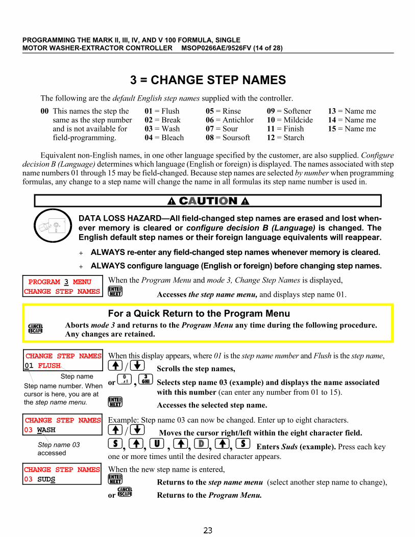
Ê3 = CHANGE STEP NAMESThe following are the default English step names supplied with the controller.
00 This names the step the same as the step numberand is not available forfield-programming.
01 = Flush02 = Break03 = Wash04 = Bleach
05 = Rinse06 = Antichlor07 = Sour08 = Soursoft
09 = Softener10 = Mildcide11 = Finish12 = Starch
13 = Name me14 = Name me15 = Name me
Equivalent non-English names, in one other language specified by the customer, are also supplied. Configuredecision B (Language) determines which language (English or foreign) is displayed. The names associated with stepname numbers 01 through 15 may be field-changed. Because step names are selected by number when programmingformulas, any change to a step name will change the name in all formulas its step name number is used in.
DATA LOSS HAZARD—All field-changed step names are erased and lost when-ever memory is cleared or configure decision B (Language) is changed. TheEnglish default step names or their foreign language equivalents will reappear.
+ ALWAYS re-enter any field-changed step names whenever memory is cleared.
+ ALWAYS configure language (English or foreign) before changing step names.
PROGRAM 3 MENU CHANGE STEP NAMES
When the Program Menu and mode 3, Change Step Names is displayed,
Accesses the step name menu, and displays step name 01.
Ë For a Quick Return to the Program MenuAborts mode 3 and returns to the Program Menu any time during the following procedure. Any changes are retained.
.CHANGE STEP NAMES01 FLUSH
When this display appears, where 01 is the step name number and Flush is the step name,
/ Scrolls the step names,
or , Selects step name 03 (example) and displays the name associatedwith this number (can enter any number from 01 to 15).
Accesses the selected step name.
CHANGE STEP NAMES03 WASH
Example: Step name 03 can now be changed. Enter up to eight characters.
/ Moves the cursor right/left within the eight character field.
, , , , , , Enters Suds (example). Press each keyone or more times until the desired character appears.
CHANGE STEP NAMES03 SUDS
When the new step name is entered,
Returns to the step name menu (select another step name to change),
or Returns to the Program Menu.
Step name
Step name number. Whencursor is here, you are atthe step name menu.
Step name 03accessed
PROGRAMMING THE MARK II, III, IV, AND V 100 FORMULA, SINGLEMOTOR WASHER-EXTRACTOR CONTROLLER MSOP0266AE/9526FV (14 of 28)

Ê4 = CHANGE CHEM NAMESThe following are the default English chemical names supplied with the controller.
00 This names the chem-ical the same as the chem number and is not available for field-programming.
01 = Alkali02 = Soap03 = Detergent04 = Soap+alkali05 =Deterg+alkali
06 = Chlorine Bleach07 = Oxygen Bleach08 = Antichlor09 = Sour10 = Softener
11 = Sour+softener12 = Starch13 = Anti-mildew14 = Anti-bacteria15 = Finishing Chems16-64 = Chem Name xx
Equivalent non-English names, in one other language specified by the customer, are also supplied. Configure deci-sion B, Language, determines which language (English or foreign) is displayed. The names associated with chem namenumbers 01 through 64 may be field-changed. Because chemical names are selected by number when programmingformulas, any change to a chemical name will change the name in all formulas its chem name number is used in.
DATA LOSS HAZARD—All field-changed chemical names are erased and lostwhenever memory is cleared or configure decision B (Language) is changed. TheEnglish default chemical names or their foreign language equivalents will reappear.
+ ALWAYS re-enter any field-changed chemical names whenever memory is cleared.
+ ALWAYS configure language (English or foreign) before changing chemical names.
PROGRAM 4 MENU CHANGE CHEM NAMES
When the Program Menu and mode 4, Change Chem Names is displayed,
Accesses the chemical name menu and displays the first editable name.
Ë For a Quick Return to the Program MenuAborts mode 4 and returns to the Program Menu any time during the following procedure. Any changes are retained.
CHANGE CHEM NAMES01 ALKALI
When this display appears, where 01 is the chemical name number and Alkali is the chemical name,
/ Scrolls the chemical names,
or , Selects chemical name 13 (example) and displays the nameassociated with this number (can enter any number from 01 to 64).
Accesses the selected chemical name.
CHANGE CHEM NAMES13 ANTI-MILDEW
Example: Chemical name 13 can now be changed. Enter up to 15 characters.
/ Moves the cursor right/left within the 15 character field.
, , , , , , , , , etc. Enters Mildistat(example). Press each key one or more times until desired character appears.
CHANGE CHEM NAMES13 MILDISTAT
When the new chemical name is entered,
Returns to the chemical name menu (select another name to change),
or Returns to the Program Menu.
Chemical name
Chemical name numberWhen cursor is here,you are at the chemicalname menu.
Chemical name 13
PROGRAMMING THE MARK II, III, IV, AND V 100 FORMULA, SINGLEMOTOR WASHER-EXTRACTOR CONTROLLER MSOP0266AE/9526FV (15 of 28)

Ê5 = CONFIGURE (and Why It Is Necessary)Because the controller software is written to accommodate different machine models and options as well as
certain user preferences (e.g., which language to display), it is necessary to configure the controller to match eachspecific machine. Hardware-based configure decisions must match the machine hardware and they must be changedto match subsequent hardware changes. User preferences may be set and subsequently changed as desired.
ËWhere To Find Configure Requirements—See “IMPORTANT OWNER/USER INFORMATION . . .”(see Table of Contents) for the circumstances that require reconfiguring and reprogramming. The metal configurenameplate on the machine shows factory configuration. Make all hardware-based configure decisions conform tothis nameplate, except to conform to any subsequent hardware changes. All configure decisions are explained in thissection. Decisions are marked to indicate which are discretionary and which are hardware-based.
ËHow To Access, Move Through, and Exit Program Mode 5, CONFIGURE and Use the Help Screens—The configure mode has two pages consisting of several decisions, each witha help screen. It also has several additional screens. Once you have accessed configure, you must move throughall decisions to exit and return to the Program Menu. However, you need not view the help screens.
PROGRAM 5 MENU CONFIGURE
When the Program Menu and mode 5, Configure is displayed,
Accesses mode 5, Configure and displays page AT. See FIGURE 3.
ÎFIGURE 3 (MSOP0234BE)
ÎHow To Move Around in Configure and Using the Help Screens
PROGRAMMING THE MARK II, III, IV, AND V 100 FORMULA, SINGLEMOTOR WASHER-EXTRACTOR CONTROLLER MSOP0266AE/9526FV (16 of 28)

ÊThe Configure DecisionsA few configure decisions on page AT influence subsequent configure decisions on page AT and page UZ. For
example, decision H (steam error)=1 mandates decision T (temp probes)=1 or 2. Although the control does notprevent the user from incorrectly entering T=0 in this instance, it will subsequently insert the value one. If the usercommands T=2, the control will retain this value. Other similar lockouts are built into the configure decisions.
Several of the additional screens that follow page UZ, will only appear if certain values are entered for certainprevious decisions. All possible screens are shown and explained here.
ÏConfigure Decisions for Pages AT and UZ
Configure Decision(Page and Help Screen)
D=Discretionary H=Must Accommodate Hardware
Selections Explanation
Page AT
ABCDEFGHIJKLMNOPQRST A TEMP UNIT 1 CENTIGRADE
D 0=Fahrenheit, inches,and month/day/year1=Celsius, centimeters,and day/month/year
Determines temperature units, length units, and dateformat for display and hard copy.
ABCDEFGHIJKLMNOPQRST B LANGUAGES 0 ENGLISH
D 0=English1=Foreign
Specifies whether to display prompts, messages,step names and chemical names in English or thecustomer-specified non-English language.
DATA LOSS HAZARD—If step or chemical nameswere field programmed, these can be lost if thelanguage choice is changed now. See modes 3 and 4.
ABCDEFGHIJKLMNOPQRST C MACHINE TYPE 0 30022F8W
H 0=30022F8W1=42032F7P2=3630 STAPHGUARD
Configure decisions D and E are not currently used.
ABCDEFGHIJKLMNOPQRST F ANTI-PLUG 0 1.7 SECS
H Decision appears, butneedn’t be configuredas Decision YYY willoverride any valueentered here.
This is the dwell time between when the wash motorturns off and restarts in the reverse direction.
MACHINE DAMAGE HAZARD—A shorter dwell timethan the factory selection can damage wash motor orbelt/gear train. Longer dwell times are acceptable.
C
F
PROGRAMMING THE MARK II, III, IV, AND V 100 FORMULA, SINGLEMOTOR WASHER-EXTRACTOR CONTROLLER MSOP0266AE/9526FV (17 of 28)

Configure Decision(Page and Help Screen)
D=Discretionary H=Must Accommodate Hardware
Selections Explanation
ABCDEFGHIJKLMNOPQRST DRAIN G BATH EXTRACT (SEC) 0 30 30
H BATH EXTR E1-2 0= 30 30 45 1= 45 45 602= 60 60 903= 75 75 1054= 90 90 905= 90 120 1206= 30 60 90
This is drain time in seconds after each bath orbefore each extract, and also the delay time from E1to E2 (low to high speed extract) if machine has twospeed extract (see configure decision D, page AT).
MACHINE MALFUNCTION AND DAMAGE HAZARDS—Shorter drain times than the factory selection may notpermit a full drain before extract, resulting in possibledamage to either or both extract motors. Longer draintimes are acceptable.
ABCDEFGHIJKLMNOPQRST H STEAM ERROR 1 5 MIN
H
D
0=no steam1=5 minutes2=10 minutes3=50 minutes
Steam injection is standard on certain machines andoptional on others. It permits steaming for timeindicated before the too long to steam error appears.
ABCDEFGHIJKLMNOPQRST I FILL ERROR 0 3 MIN
D 0=3 minutes1=5 minutes2=10 minutes3=15 minutes
Permits filling for the time indicated before the toolong to fill error appears.
ABCDEFGHIJKLMNOPQRST COOLDOWN J ERROR 1 5 MIN
H
D
0=no cooldown1=5 minutes2=10 minutes3=50 minutes
Cooldown is standard on certain machines andoptional on others. It permits cooling down for timeindicated before the too long to cool error appears.
ABCDEFGHIJKLMNOPQRST WATER OPT K H+C 0
H 0=hot + cold water valves (standard in America)1=cold + 2nd water valves (standard in Europe and other areas)2=hot + cold + 3rd water valves (optional)3=cold + 2nd + 3rd water valves (optional)
ABCDEFHIJKLMNPOPQRST REUSE OPT. L NO [1=YES] 0
H 0=no1=yes
Optional reuse tank permits draining to sewer orreuse (as commanded in formula programming).
ABCDEFGHIJKLMNOPQRSTO/H TANK MNO [1=YES] 0
H 0=no1=yes
Optional overhead tank allows collection of bathliquor for future use.
ABCDEFGHIJKLMNOPQRST METERED WATER N NO [1=YES] 0
H 0=no1=yes
Optional metered water feature provides forcommanding a metered quantity of water for eachbath of a formula.
Configure decision O is not currently used.
Configure Decisions for Pages AT and UZ, continued
C
PROGRAMMING THE MARK II, III, IV, AND V 100 FORMULA, SINGLEMOTOR WASHER-EXTRACTOR CONTROLLER MSOP0266AE/9526FV (18 of 28)

Configure Decision(Page and Help Screen)
D=Discretionary H=Must Accommodate Hardware
Selections Explanation
ABCDEFGHIJKLMNOPQRST BALANCING OPT P NO [1=YES] 0
H 0=no1=yes
Hydraulic (water) balancing feature is standard oncertain machines. It is not an option. Answer 1(yes)if speed sensing and automatic RPM adjusting isdesired.
ABCDEFGHIJKLMNOPQRST RECIRC. Q NO[1=YES] 0
H 0=no1=yes
Optional recirculation permits water spray throughthe load door.
Configure decision R is not currently used.
ABCDEFGHIJKLMNOPQRST AMPSAVER OPT S NO [1=YES] 0
H 0=no1=yes
Optional ampsaver feature reduces maximumamperes required by a group of machines.
ABCDEFGHIJKLMNOPQRST TEMP PROBES T 1 TEMP PROBE 1
H 0=no temperatureprobes
1=one probe2=two probes
Number of temperature probes depends on modeland method of filling with water.
Page UZ
UVWXYZ U ELEC. LEVEL 0 NO [1=YES]
H 0=no1=yes
As of this writing, electronic level sensing isstandard on machines with the nameplate modeldesignation xxxxxExN (e.g., 64046E6N) only. It isnot an option.
Configure decision V is not currently used.
UVWXYZ W VARIABLE SPD OPT 1 VARIABLE SPEED
H 0=no1=yes
As of this writing, variable speed is standard onsome machines, optional on some machines, andnot available on some machines. Variable speedapplies to wash speed only on some machines andto both wash and extract speeds on other machines.Answer 1(yes) if speed sensing and automatic RPMadjusting desired.
MACHINE MALFUNCTION AND DAMAGEHAZARDS—The variable speed inverter wasprogrammed at the factory. The constants arewritten inside the electrical box housing the inverter.Changing these constants may result in damage togoods or the machine.
Configure Decisions for Pages AT and UZ, continued
E
PROGRAMMING THE MARK II, III, IV, AND V 100 FORMULA, SINGLEMOTOR WASHER-EXTRACTOR CONTROLLER MSOP0266AE/9526FV (19 of 28)

Configure Decision(Page and Help Screen)
D=Discretionary H=Must Accommodate Hardware
Selections Explanation
UVWXYZ X MANUAL PASSWORD 1 YES [0=NO]
D 0=no—Password(numerical pass code)not required for manual modifications to arunning formula.1=yes—Password reqd..
Configure decisions Y and Z are not currently used.
ÏAdditional Configure Screens
Configure Decision(Screen)
D=DiscretionaryH=Must Accommodate Hardware
Selections/Range Explanation
Password (numeric pass code) Screen (only appears if decision X, page UZ = 1)
PASSWORD: 1234
D 0000-9999 The four digit pass code configured here must beentered by the operator before making manualformula modifications.
Electronic Level Sensing Screens (only appear if decision U, page UZ = 1)
NOTE: Low, med, and high levels shown below only provide safety lockouts. They do not set the levels for themachine; thus, they do not coincide with the traditional levels one (low), two (wash), and three (rinse). See “AD-JUSTING LEVEL SENSING APPARATUS . . . ” for more information.
LOW LEVEL 06
D Inches (Centimeters)
4-6 (14-15)
Minimum level that can be commanded for anybath and thus, the minimum level required forsteaming.
MED LEVEL 10
D 6-10 (15-25) Minimum level required in a bath preceeding anextract. If a lower level is commanded, the controlwill insert the value configured here when the washformula is saved.
HIGH LEVEL 16
D 10-16 (25-40) Maximum level that can be commanded for anybath.
TAP OFFSET COUNTS 0000
H 0000-9999 counts This value adjusts the transducer output to compen-sate for offsetting conditions (such as location oflevel sensor) specific to each machine. It is deter-mined for each machine at the factory (see configurenameplate), but may be re-calibrated in the field.
To Calibrate Tap Offset Counts—Measure and mark alevel in the basket (e.g., 10 inches (25 centimeters)) thencommand this level. If the level achieved is lower thanmarked, increase tap offset counts. If the level achieved ishigher than marked, decrease tap offset counts, or if tap offset counts = 0000, consult the Milnor® factory.
ENTRAPMENT HAZARD—You can be injured or killedif you become trapped in the washer cylinder.+ Procedure must be done only by trained personnel.+ Lock off and tag out power at the external disconnect before entering washer cylinder.
Configure Decisions for Pages AT and UZ, continued
B
PROGRAMMING THE MARK II, III, IV, AND V 100 FORMULA, SINGLEMOTOR WASHER-EXTRACTOR CONTROLLER MSOP0266AE/9526FV (20 of 28)

Configure Decision(Screen)
D=DiscretionaryH=Must Accommodate Hardware
Selections/Range Explanation
Screens that Always Appear (not dependent on prior configure decisions)
# OF CHEM VALVES 05
H 00-15 valves This is the number of valves or pumps used to injectchemicals, whether flush valves on an optionalflushing supply injector, peristaltic pumps (suppliedby others) or optional liquid supply valves. Do notcount the manifold flush valve, if any.
DRAIN WASH OUT SS 00
D 00-45 seconds If a no-water bath is commanded (to shake outloose, dry soil) and do not drain is not commandedfor a bath’s drain, when the drain valve opens at theend of the bath, the cold water valve also opens forthe shorter of the time stipulated here or the draintime stipulated in configure decision G.
AUTOSPOT RPM: 02
D 1-40 Enter the speed the cylinder turns during Autospot.
MACHINE NAME 30022F8W MACHINE 07
D Any name (up to 20 characters) to identify this machine. Name appears onhard copy when mode 8, Print Data on the Program Menu is used.
Machine name field (20 characters)
/ Moves the cursor right/left within the machine name field.<x> Enters a character in the current cursor position, where <x> is any keypad character.
Accepts the displayed machine name and advances to the next decision.
SIMULATOR VERSION? 0 NO [1=YES]
H 0 = no1 = yes
Select 1 = yes only if this is a simulator. If yes,board will not operate a washer-extractor or anyoutputs, but the simulator can send data to a printeror download to a machine or tape.
MILDATA 1 YES [0=NO]
H 0 = no—Machine does not communicate with a Mildata® computer1 = yes —Machine communicates with a Mildata® computer
Mildata Screens (only appear if Mildata? above = 1)
MILDATA ADDRESS? 005
H 000-255 This value must match the address (discreteindentification code) assigned to this machine in theMildata® computer. See Mildata® manual.
Additional Configure Screens, continued
F
PROGRAMMING THE MARK II, III, IV, AND V 100 FORMULA, SINGLEMOTOR WASHER-EXTRACTOR CONTROLLER MSOP0266AE/9526FV (21 of 28)

Configure Decision(Screen)
D=DiscretionaryH=Must Accommodate Hardware
Selections/Range Explanation
DATA FWGCEWPL ENTRY 10000000
D For each of thefollowing, 0=no and1=yes
Permits Mildata® accounting by the code categoriesenabled here.
Formula FWork Order WGoods Code GCustomer Code CEmployee Code EWeight WPieces PLot Number L
0 or 1, but 1 inserts 0 in next two decisions and skips them.0 or 1 if formula above = 0, otherwise must be 0 and cursor skips over.0 or 1 if formula and work order above are both = 0. Otherwise must be 0.0 or 1 if work order above = 0. Otherwise must be 0.0 or 10 or 10 or 10 or 1
For each of the above,<x> Enters no or yes, where <x> is 0 or 1. Cannot scroll decisions or values. Do not use / .
Accepts the selected choice and advances to the next decision. Cursor moves forward only.
Metered Water Screens (only appear if decision N, page AT = 1)
COUNTS PER 100 1483
D 0000-9999 Establishes the units measured by the electronicflowmeter. Enter the number of flowmeter countsresulting from flowing 100 gallons, 100 liters, etc.,whichever is the unit of choice. The same unit mustbe used when programming formulas. Seeflowmeter calibration procedures.
OFFSET VALVE TIME 048
H 000-255 tenths ofseconds
Reduces, by the value entered here, the time thewater valve will open to admit the metered quantitycommanded. This compensates for the tendancy ofthe valve/flowmeter to overshoot the commandedquantity. See flowmeter calibration procedures.
NOTE: Discharge time, discharge dwell time, and number of discharge sequences, below, control basket rota-tion and duration of discharge. Use these configure decisions to ensure all goods are discharged.
PROGRAMMING THE MARK II, III, IV, AND V 100 FORMULA, SINGLEMOTOR WASHER-EXTRACTOR CONTROLLER MSOP0266AE/9526FV (22 of 28)

Ê6 = DOWN LOAD
ËWhat Downloading Does—Downloading transfers all formulas, step names, chemical names, and configurecodes (if specified) from one machine to another via a serial communication cable. This eliminates the need to enterthe same data repeatedly. It can also transfer this data between a machine and a Milnor® serial downloader (Mil-nor® part number KXMIC00508) for convenient data retrieval in the event of computer memory loss.
Downloading completely replaces all of the above mentioned data (configure codes are downloaded only ifspecifically commanded). Selective downloading (e.g., transferring only certain wash formulas) is not possible.
ËWhen and When Not To Download—The reliability and usefulness of downloaded data depends on thesimilarity between the sending machine and any receiving machines. Abide by the following table.
Similarity between sending and receiving machines Should you download? Actions required after
downloadingSoftware Basic model OptionsIdentical Identical Identical Yes –include configure. noneIdentical Identical Different Ok–probably exclude configure. Check configure (see caution).Identical Different Different Probably not. Reconfigure then revise formulas.Different doesn’t matter doesn’t matter No—will result in scrambled, unusable data.
MACHINE MALFUNCTION HAZARD—Machine may malfunction, possibly causing unsafe opera-tion, damage to machine and/or damage to goods if not properly configured.
+ After downloading, reconfigure in accordance with each receiving machine’s configure name-plate. This may be omitted only where all machines have identical configurations.
ËThe General Procedure—Downloading is done in the following stages:
1. Connect all participating devices via a temporary serial cable (if a permanent cable is not already installed).
2. Set up each machine (not the serial downloader), using mode 6, Download.
3. Initiate and monitor the downloading.
ÊMaking Connections
ËMachine To Machine—If a serial cable is not permanently installed (in conduit) between participating ma-chines, install a temporary cable. See “THE EXTERNAL SERIAL LINK CABLES . . .” (see Table of Contents).
MACHINE MALFUNCTION HAZARD—Temporary cables (not enclosed in conduit) are susceptableto electromagnetic interference (EMI) which can disrupt machine operation.
+ Remove temporary cable as soon as downloading is completed.
ËMachine To/From Serial Downloader—Two sets of instructions appear on the downloader: To Down-load—copying data from a machine to the downloader and To Upload—copying data from the downloader toone or more machines. Connect the lead from the downloader box to the Printer/Download socket on the machine(step 1 on the downloader instructions for both downloading and uploading). Ready light should be on.
PROGRAMMING THE MARK II, III, IV, AND V 100 FORMULA, SINGLEMOTOR WASHER-EXTRACTOR CONTROLLER MSOP0266AE/9526FV (23 of 28)
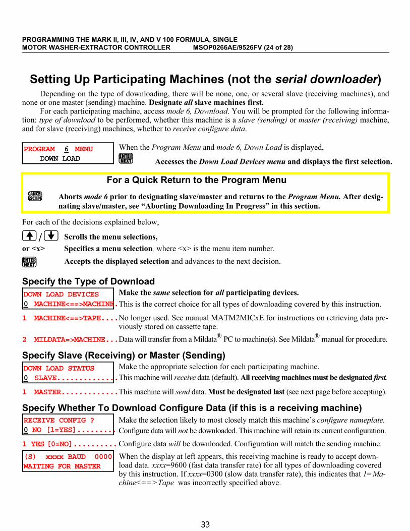
ÊSetting Up Participating Machines (not the serial downloader)Depending on the type of downloading, there will be none, one, or several slave (receiving machines), and
none or one master (sending) machine. Designate all slave machines first. For each participating machine, access mode 6, Download. You will be prompted for the following informa-
tion: type of download to be performed, whether this machine is a slave (sending) or master (receiving) machine,and for slave (receiving) machines, whether to receive configure data.
PROGRAM 6 MENU DOWN LOAD
When the Program Menu and mode 6, Down Load is displayed,
Accesses the Down Load Devices menu and displays the first selection.
Ë For a Quick Return to the Program Menu
Aborts mode 6 prior to designating slave/master and returns to the Program Menu. After desig-nating slave/master, see “Aborting Downloading In Progress” in this section.
For each of the decisions explained below,
/ Scrolls the menu selections,
or <x> Specifies a menu selection, where <x> is the menu item number.
Accepts the displayed selection and advances to the next decision.
ËSpecify the Type of DownloadDOWN LOAD DEVICES0 MACHINE<==>MACHINE.
Make the same selection for all participating devices.
This is the correct choice for all types of downloading covered by this instruction.
1 MACHINE<==>TAPE....No longer used. See manual MATM2MICxE for instructions on retrieving data pre-viously stored on cassette tape.
2 MILDATA=>MACHINE...Data will transfer from a Mildata® PC to machine(s). See Mildata® manual for procedure.
ËSpecify Slave (Receiving) or Master (Sending)DOWN LOAD STATUS0 SLAVE..............
Make the appropriate selection for each participating machine.This machine will receive data (default). All receiving machines must be designated first.
1 MASTER.............This machine will send data. Must be designated last (see next page before accepting).
ËSpecify Whether To Download Configure Data (if this is a receiving machine)RECEIVE CONFIG ?0 NO [1=YES].........
Make the selection likely to most closely match this machine’s configure nameplate.Configure data will not be downloaded. This machine will retain its current configuration.
1 YES [0=NO]..........Configure data will be downloaded. Configuration will match the sending machine.
(S) xxxx BAUD 0000WAITING FOR MASTER
When the display at left appears, this receiving machine is ready to accept down-load data. xxxx=9600 (fast data transfer rate) for all types of downloading coveredby this instruction. If xxxx=0300 (slow data transfer rate), this indicates that 1=Ma-chine<==>Tape was incorrectly specified above.
PROGRAMMING THE MARK II, III, IV, AND V 100 FORMULA, SINGLEMOTOR WASHER-EXTRACTOR CONTROLLER MSOP0266AE/9526FV (24 of 28)

ÊInitiating, Monitoring, and Aborting a DownloadOnce any receiving machine is set-up and awaiting data, downloading may be initiated. Displays are provided
for monitoring the progress of downloading. You may abort the download process at any time. However, if adownload in progress is halted, all receiving devices will contain a mixture of old and new data, and will notoperate properly until program memory is successfully downloaded or reprogrammed.
ËInitiating Downloading
Between MachinesMachine to Serial Downloader (see To Upload on downloader box)
Serial Downloader to Machine(see To Download on downloader
box)
1. Designate master. Downloadingbegins immediately.
1. Clear memory in the serialdownloader as explained in the To Upload instructions on theserial downloader.
2. Designate master. Uploadingbegins immediately.
1. Command Transmit, as explained in the To Download instructions on the serial
downloader.
ËMonitoring Downloading in Progress
The displays at left appear during downloading, wherexxxx is a scrolling hexadecimal number, indicating bytelocation currently downloading. At 9600 baud, down-loading takes about one minute. While downloadingto/from the serial downloader, the Transmit light or Re-ceive light (as appropriate) should be on. When down-loading is successfully completed,
On each machine, returns to Program Menu.
NOTE: After downloading to the serial down-loader, label the downloader with the machinemodel and software version.
If, during downloading, either display shown at leftappears on a receiving machine, data transfer to thatmachine was unsuccessful. If the Receive light failsto illuminate when downloading from a machine tothe serial downloader, data transfer was unsuccess-ful. Check the serial cable connections and repeat thedownload process.
ËAborting Downloading In Progress
Aborts the download process for any receiving machine on which it is commanded, or for all ma-chines if commanded on the sending machine. The machine receiving the abort command displays thefollowing:
DOWN LOAD ABORTED NEXT TO PROCEED
Repeat the download process for any receiving machine on which downloadingwas aborted; otherwise, the machine will contain a mixture of old and new data.
Normal Displays During Downloading:
(M) 9600 BAUD xxxxRECEIVING DATA
(S) 9600 BAUD xxxx TRANSFERRING DATA
Slave (receiving) machines Master (sending) machine
Display indicating successful com-pletion (appears on all machines):
PROCESS COMPLETED NEXT TO PROCEED
Error Displays During Downloading:
(S) 9600 BAUD 000WAITING FOR MASTER
ERROR IN CHECK SUMNEXT TO PROCEED
C
PROGRAMMING THE MARK II, III, IV, AND V 100 FORMULA, SINGLEMOTOR WASHER-EXTRACTOR CONTROLLER MSOP0266AE/9526FV (25 of 28)

Ê7 = CLEAR ALL MEMORY (VOLUNTARILY)This mode clears all user-programmed formulas, step names, and chemical names on command. The step
names and chemical names originally supplied with the machine will reappear. Configure codes are unaffectedwhen memory is cleared voluntarily, but the control must be reconfigured after first commissioning the machine orafter the display says Clear Memory Now. See “IMPORTANT OWNER/USER INFORMATION . . .” (see Tableof Contents).
PROGRAM 7 MENU CLEAR ALL MEMORY
When the Program Menu and mode 7, Clear All Memory, is displayed,
Accesses mode 7 and prompts the user to clear memory or cancel.
Ë For a Quick Return to the Program Menu
Aborts mode 7 without clearing memory and returns to the Program Menu.
DATA LOSS HAZARD—The following key strokes will delete all user programmed data.
+ If this mode was entered accidently, press to cancel this procedure.
4+5+6=CLEAR MEMORY CANCEL = ESCAPE
When this display appears (no cursor),
+ + Clears all user-programmed formulas, step names, and chemical names.
CLEARING MEMORY**PLEASE WAIT**
This display appears while the controller is clearing memory. When memory iscleared, the display returns to the Program Menu.
or Aborts mode 7 without clearing memory. Display returns to the Program Menu.
PROGRAMMING THE MARK II, III, IV, AND V 100 FORMULA, SINGLEMOTOR WASHER-EXTRACTOR CONTROLLER MSOP0266AE/9526FV (26 of 28)

Ê8 = PRINT DATAThis mode permits printing the current formulas, configure codes, chemical names, and step names (see FIGURE
4) on a printer that meets the requirements explained in “REQUIREMENTS AND SETTINGS FOR THE EPSONLX300 PRINTER” (see Table of Contents). The printer is connected to the machine through the Printer/Download socket.A mating plug is provided with the machine for wiring the printer interface cable. See “THE EXTERNAL SERIALLINK CABLES. . .”.
PROGRAM 8 MENU PRINT DATA
When the Program Menu and mode 8, Print Data is displayed,
Accesses mode 8 and prompts for the type of data to print.
Ë For a Quick Return to the Program Menu
Aborts mode 8 any time prior to the start of printing and returns to the Program Menu.
PRINT DATA0 FORMULAS...........
When this display appears, select the type of data to print from the choices shown.
Prints formulas 00, 99, and the range of formulas specified below.
1 CONFIGURATION......Prints the configure codes.
2 CHEMICAL NAMES.....Prints the 64 field-programmable chemical names.
3 STEP NAMES.........Prints the 15 field-programmable step names.
or Scrolls the choices
Accepts the selected choice and prompts for today’s date.
This display permits entering today’s date, which will appear on the printout. mm,dd, and yyyy are numbers representing month, day, and year, respectively. Notethat month/day or day/month order depends on configure decision A. The date is re-tained (in unprotected memory) for about 48 hours with power off.<mm> or <dd> or <yyyy> enters a value at the indicated cursor location,
where <mm> is a number from 01 to 12, representing the month, <dd>is a number from 01 to 31 representing the day, and <yyyy> is a
number representing the year (e.g., 1993).
Accepts the displayed value and advances to next field or decision.
START STOP xx yy
This display only appears if Formulas was selected above. Formulas 00 and 99 arealways printed. Enter the range of additional formulas to be printed, where xx is thestarting formula and yy is the ending formula, inclusive.
<xx>, Enters the lowest formula number, where <xx> is greater than 00and less than or equal to <yy>.
<yy>, Enters the highest formula number, where <yy> is greater than orequal to <xx> and less than 99. Printing begins.
DATE: MM - DD -YYYYmm - dd -yyyy
When configure decision A=0
When configure decision A=1
DATE: DD - MM -YYYYdd - mm -yyyy
PROGRAMMING THE MARK II, III, IV, AND V 100 FORMULA, SINGLEMOTOR WASHER-EXTRACTOR CONTROLLER MSOP0266AE/9526FV (27 of 28)

PRINTING . . . . ** PLEASE WAIT **
During printing, this display appears. When printing is concluded, the display re-turns to the Program Menu.
ÎFIGURE 4 (MSOP0234BE)
ÎExample Printouts Using Mode 8, Print Data
C
PROGRAMMING THE MARK II, III, IV, AND V 100 FORMULA, SINGLEMOTOR WASHER-EXTRACTOR CONTROLLER MSOP0266AE/9526FV (28 of 28)


Section 3Operating
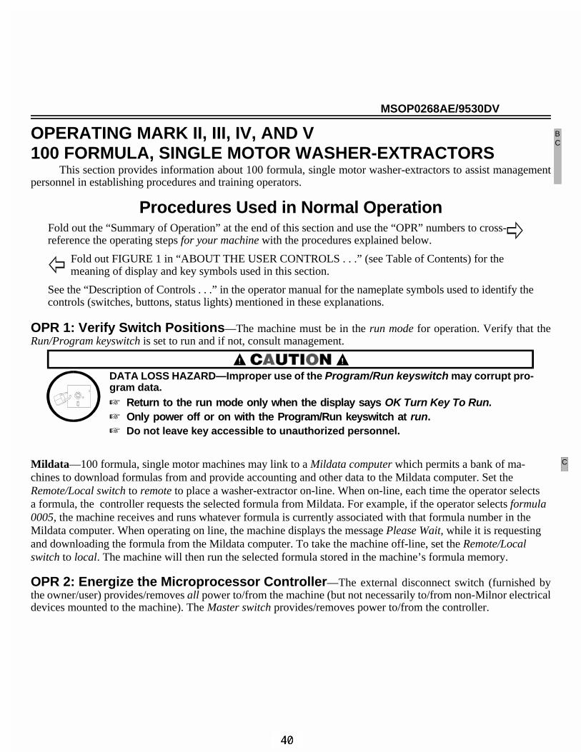
MSOP0268AE/9530DV
OPERATING MARK II, III, IV, AND V100 FORMULA, SINGLE MOTOR WASHER-EXTRACTORS
This section provides information about 100 formula, single motor washer-extractors to assist managementpersonnel in establishing procedures and training operators.
Procedures Used in Normal OperationFold out the “Summary of Operation” at the end of this section and use the “OPR” numbers to cross-reference the operating steps for your machine with the procedures explained below.
Fold out FIGURE 1 in “ABOUT THE USER CONTROLS . . .” (see Table of Contents) for the meaning of display and key symbols used in this section.
See the “Description of Controls . . .” in the operator manual for the nameplate symbols used to identify thecontrols (switches, buttons, status lights) mentioned in these explanations.
OPR 1: Verify Switch Positions—The machine must be in the run mode for operation. Verify that theRun/Program keyswitch is set to run and if not, consult management.
DATA LOSS HAZARD—Improper use of the Program/Run keyswitch may corrupt pro-gram data.� Return to the run mode only when the display says OK Turn Key To Run.� Only power off or on with the Program/Run keyswitch at run.� Do not leave key accessible to unauthorized personnel.
Mildata—100 formula, single motor machines may link to a Mildata computer which permits a bank of ma-chines to download formulas from and provide accounting and other data to the Mildata computer. Set theRemote/Local switch to remote to place a washer-extractor on-line. When on-line, each time the operator selectsa formula, the controller requests the selected formula from Mildata. For example, if the operator selects formula0005, the machine receives and runs whatever formula is currently associated with that formula number in theMildata computer. When operating on line, the machine displays the message Please Wait, while it is requestingand downloading the formula from the Mildata computer. To take the machine off-line, set the Remote/Localswitch to local. The machine will then run the selected formula stored in the machine’s formula memory.
OPR 2: Energize the Microprocessor Controller—The external disconnect switch (furnished bythe owner/user) provides/removes all power to/from the machine (but not necessarily to/from non-Milnor electricaldevices mounted to the machine). The Master switch provides/removes power to/from the controller.
BC
C

ELECTROCUTION AND ELECTRICAL BURN HAZARDS—Contact with high voltage willelectrocute or burn you. Power switches on the machine and the control box do noteliminate these hazards. High voltage is present at the machine unless the externaldisconnect switch is off.
� Do not unlock or open electric box doors.
� Do not remove guards, covers or panels.
� Do not reach into the machine housing or frame.
� Keep yourself and others off of machine.
� Know the location of the external disconnect switch and use it in an emergency to remove allelectric power from the machine.
To power-up the machine, verify that all utilities (electricity, water, air, and steam) and chemicals are on,set the Master switch to on, and view the start-up displays, as follows:
COPYRIGHT PELLERINMILNOR 1994
Copyright statement (may repeat).
ALL RIGHTS RESERVED’OUTERWEAR ’94003/S
Example software date code/language version (/S indicates English/Spanishversion).
FORMULA CHECK SUM02C8
The checksum changes with any programming changes. Record the check-sumafter each programming session, to protect against unauthorized programming.
On Staph-Guard type machines, the Soil Side light ( ) illuminates at this time.
OPR 4A: Open/Close Soil Door—Hold the Autospot button ( + ) and Unlock Door button ( )simultaneously until the display says Autospotting Is Completed and the operator signal sounds. The soil cylinder
door will be aligned with the soil shell door. Release the buttons. Hold the Unlock door button ( ) until the locksrelease (7 second delay) and open the outer door.
Open the cylinder door as follows:
1. Push the uppermost latches toward the door with your thumbs while holding the handle (see Figure 3).The latches will release the door and cause it to drop down.
FIGURE 1 (MSOP0268AE)
View of Cylinder Doorfrom Side of Machine
FIGURE 2 (MSOP0268AE)
Correct Hand Position forReleasing Top Door Locks
FIGURE 3 (MSOP0268AE)
Releasing TopDoor Locks
CD
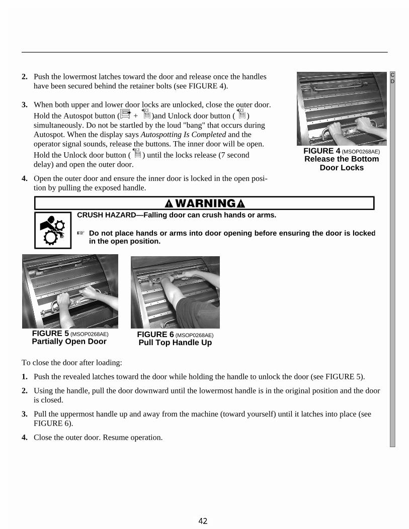
2. Push the lowermost latches toward the door and release once the handleshave been secured behind the retainer bolts (see FIGURE 4).
3. When both upper and lower door locks are unlocked, close the outer door.Hold the Autospot button ( + )and Unlock door button ( )simultaneously. Do not be startled by the loud "bang" that occurs duringAutospot. When the display says Autospotting Is Completed and theoperator signal sounds, release the buttons. The inner door will be open.Hold the Unlock door button ( ) until the locks release (7 seconddelay) and open the outer door.
4. Open the outer door and ensure the inner door is locked in the open posi-tion by pulling the exposed handle.
CRUSH HAZARD—Falling door can crush hands or arms.
� Do not place hands or arms into door opening before ensuring the door is lockedin the open position.
To close the door after loading:
1. Push the revealed latches toward the door while holding the handle to unlock the door (see FIGURE 5).
2. Using the handle, pull the door downward until the lowermost handle is in the original position and the dooris closed.
3. Pull the uppermost handle up and away from the machine (toward yourself) until it latches into place (seeFIGURE 6).
4. Close the outer door. Resume operation.
FIGURE 4 (MSOP0268AE)
Release the BottomDoor Locks
FIGURE 5 (MSOP0268AE)
Partially Open Door FIGURE 6 (MSOP0268AE)
Pull Top Handle Up
CD

OPR 4B: Open/Close Shell Door—Machine power must be on to open the door. Safeguards prevent thedoor from being opened during, and immediately after, manually terminating a cycle. These safeguards are for theoperator’s protection. Never attempt to bypass them, nor operate the machine if there is any evidence of malfunc-tioning safeguards.
CRUSH, ENTANGLE AND SEVER HAZARDS—Contact with the turning cylinder cancrush your limbs. Contact with the goods being processed can cause the goods towrap around your body or limbs and dismember you. The turning cylinder and goodsare normally isolated by the locked cylinder door.
� Do not attempt to open the door or reach into the cylinder until the cylinder is stopped.
� Do not operate the machine with a malfunctioning door interlock.
� Do not touch goods inside or hanging partially outside the turning cylinder.
On Staph-Guard style machines, return control to the clean side by pressing after unloading the machineand closing the door.
OPR 5: Compose the Load and Load the Machine—The operator is responsible for maintainingproper load size, as explained in “DETERMINING LOAD SIZE” (see Table of Contents).
Effective centrifugal extraction (drawing the water from the goods by spinning the cylinder) depends onproper distribution in the cylinder. If the machine cannot adequately distribute the goods, it will be out of balanceand its vibration safety devices will prevent it from achieving normal extract speed. The knowledgeable operatorcan minimize severe imbalances and intervene to correct those that occur.
Open pocket models distribute the load by turning the cylinder at drain (distribution) speed, just prior toextract. Drain speed is just fast enough to hold the goods against the cylinder, but slow enough to permit the goodsto spread out as they pass through the draining bath.
If goods do not spread out sufficiently and a severe imbalance occurs, the machine will return to wash speedand attempt to redistribute the goods (extract recycle). Persistent recycles waste time and energy, and usually indi-cate a need for operator intervention. If goods are netted or tangled, distribution may not be possible. Observe themachine during extract and if necessary, stop the machine and untangle the goods.
OPR 6: Add Chemicals—A washer-extractor may be equipped with a five-compartment supply injector, apumped chemical system by others, or a central liquid supply system (chemical inlet valve supplied by Milnor®,chemical storage and delivery system by others). If the machine has a supply injector, the operator adds measuredquantities of chemicals to the appropriate compartments as required for each load. This is normally done before startingthe cycle, but may also be done during the cycle (see OPR 8C), if required by the formula. Management personnel whodetermine the formulas, must instruct the operator as to chemical type, quantity, and location (supply injector pocketto load) for each formula. See “USING THE FLUSHING TYPE AUTOMATIC SUPPLY INJECTOR” for moreinformation. If a pumped chemical or central liquid supply system is used, observe this system periodically to ensurethat chemicals are automatically delivered to the machine when called for.
OPR 7: Select a Formula—The machine can contain up to 98 field-programmed (local) wash formulas.The machine also contains two permanent formulas: formula 00, used to commission a new machine (explainedbelow) and formula 99, used to develop new formulas (explained in “MODIFYING FORMULAS . . .”). The ma-chine may also be connected to a Mildata computer providing access to up to 1000 (remote) formulas. With Mildata,the operator selects either a formula, a work order, or a goods code (as configured), then enters cake data. Cake datais the set of batch codes assigned to each load to identify it. It is preferable to select the formula just before startingthe cycle.
C
C
C
C

Select a local formula when the machine is not on-line to Mildata as follows:RUN FORMULA00 OR OK POWER OFF
When the Run Formula menu is displayed as shown at left,<xx> selects formula, where <xx> is a two digit number from 01 to 98.
The formula name and number appear if a valid formula was select-ed. Does Not Exist appears for a non-existent formula. A validformula sounds the operator signal, if the shell door is closed.
or / Scrolls the available formula numbers.
Select a remote formula, work order, or goods code and enter cake data when on-line to Mildata as follows:When one of the prompts shown at left appears,<response> Selects formula, work order, or goods code, where <response>
is a four, ten, or five digit number, respectively. Cannot scroll.
Accepts the value entered above.
When each prompt shown at left appears,<response> Enters the requested batch code where <response> is the number
or alpha characters described at left. Codes are determined locally.
• After each code, accepts entered value and prompts for next code. • After the last batch code, downloads the formula from Mildata®.
Formula name and number appear if valid data was entered.“INVALID FORM DATA” (or similar) appears for any invalid data.
• After formula is downloaded, displays and permits changingeach code previously entered.
Select Formula 00 to commission a new machine.—Formula 00 (see FIGURE 1) is similar to a medium soil for-mula. Because it may not take advantage of supplied options, it is only intended to help commission a new machine.It will run on any machine with two water valves to test the following:
• Filling to levels 2 and 3.• Hot, cold, and split water (or cold, 2nd, and cold+2nd, if cold only). No temperatures are commanded.• 60 second chemical injections from valves 01 through 05.• Wash reversing, intermediate extract, and final extract.• Draining to sewer. The first drain is at wash speed and all others are at distribution speed.
NOTE 1: Formula 00 is avail-able provided the machine isnot on-line to Mildata.NOTE 2: Even if the pass-word is enabled, the controllerpermits modifying formula 00(see “MANUAL FORMULAMODIFICATIONS...”) with-out the password. However,formula 00 cannot be copied,d e l e t e d , o r permanentlychanged.
FIGURE 7 (MSOP0268AE)
Printout of Formula 00 (used to commission a machine)
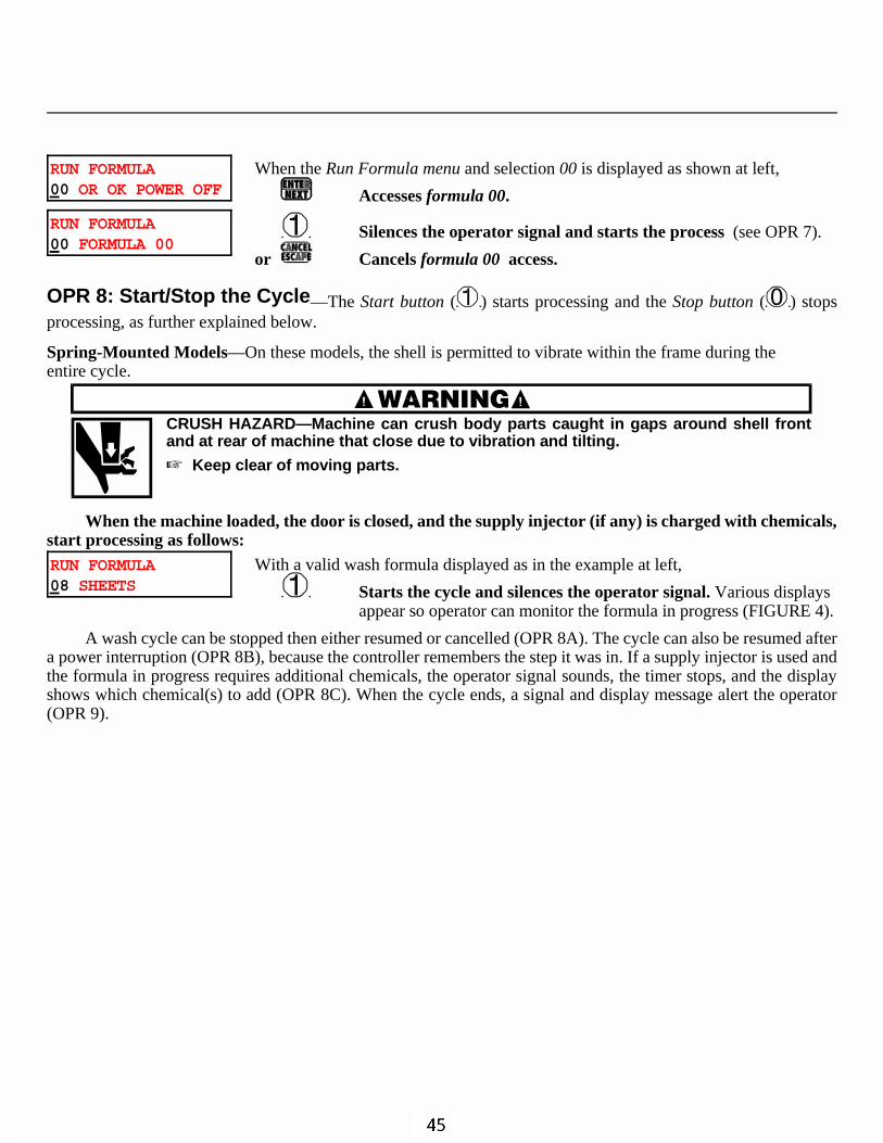
RUN FORMULA00 OR OK POWER OFF
When the Run Formula menu and selection 00 is displayed as shown at left,
Accesses formula 00.
RUN FORMULA00 FORMULA 00
Silences the operator signal and starts the process (see OPR 7).
or Cancels formula 00 access.
OPR 8: Start/Stop the Cycle—The Start button ( ) starts processing and the Stop button ( ) stopsprocessing, as further explained below.
Spring-Mounted Models—On these models, the shell is permitted to vibrate within the frame during theentire cycle.
CRUSH HAZARD—Machine can crush body parts caught in gaps around shell frontand at rear of machine that close due to vibration and tilting.
� Keep clear of moving parts.
When the machine loaded, the door is closed, and the supply injector (if any) is charged with chemicals,start processing as follows:RUN FORMULA08 SHEETS
With a valid wash formula displayed as in the example at left,
Starts the cycle and silences the operator signal. Various displaysappear so operator can monitor the formula in progress (FIGURE 4).
A wash cycle can be stopped then either resumed or cancelled (OPR 8A). The cycle can also be resumed aftera power interruption (OPR 8B), because the controller remembers the step it was in. If a supply injector is used andthe formula in progress requires additional chemicals, the operator signal sounds, the timer stops, and the displayshows which chemical(s) to add (OPR 8C). When the cycle ends, a signal and display message alert the operator(OPR 9).

OPR 8A—If necessary, stop, then either resume or cancel the wash formula in progress as follows:
Disables the three-wire circuit, immediately stopping all machine functions and displaying an error message. If this is a bath, water, chemical, and steam valves close and the drain opens, draining the machine. (See “MANUAL FORMULA MODIFICATIONS . . .” for how to stop the formula timer without draining the machine.)
3 WIRE DISABLEDFAULT: SEE MANUAL
Cancels the formula. Display returns to the Run Formula menu.
or Resumes the formula where the count left off in the interrupted step, as stipulated in the note below.
NOTE: How the machine recovers depends on whether the interruption occurred during a bath, drain, or extract. • Bath—machine achieves level and temperature again, even if these were already achieved before the
interruption. (If the machine is configured for metered water, the control prompts “REFILL WITHWATER?” Answer yes to inject the commanded quantity or no for no water.)
• Drain—the drain duration will be repeated. • Extract—the machine will perform an extract recycle.
OPR 8B—When power is restored after a power loss, resume or cancel the interrupted formula as follows:
NEXT TO RESTART ATFxxxx Syy
When the display at left appears, where xxxx and yy are the interrupted formula/step,
Confirms that the formula will be resumed,
or Cancels the formula and returns to Run Formula menu. Enter the password if requested (otherwise, resume the formula).
PRESS START When the display at left appears,
Resumes the formula at the beginning of the interrupted step, as stipulated in the note in OPR8A.
OPR 8C—Respond to the operator signal to add supplies as follows:
1. Read the display to determine chemical(s) to be added.
2. Load the supply compartment(s), add through soap chute, or flush manually as instructed locally. To flushsupplies manually, load compartment one and hold the Flush/Spray switch to manual flush.
3. Press the Signal Cancel button. If a signal only was commanded, processing resumes immediately. If a signalwith chemical was commanded, the supply compartment is flushed for the commanded time.
OPR 9: Respond to the end-of-cycle signal messagePLEASE UNLOAD ME
When the display at left appears, where message describes cylinder motion,
or Silences the signal and completes the cycle, except as follows:If message = “break cake,” cylinder motions continue until completed.If message = “tumbling,” the operator can open the door to pull downany plastered goods. After closing the door again,
Resumes “tumbling” for two minutes.

OPR 10: Jog the Cylinder to loosen the goods—Jogging (briefly turning the cylinder with thedoor open) is controlled by the operator and should be performed to loosen the goods before unloading the machine.
CRUSH HAZARDS—Contact with the turning cylinder can crush your limbs.
� Keep yourself and others clear of cylinder and goods during jogging operation.� Keep both hands on the controls while operating.� Do not operate the machine with malfunctioning manual two-hand controls.
To jog the cylinder, simultaneously hold the Start button ( ) and hold the Jog switch to either position (clockwise( ) or counter-clockwise ( ) as desired). The cylinder turns until buttons are released.

ÊSummary of OperationThe operator actions listed here correspond to the headings in “Normal Operation . . .” in the operator manual.
ËStart the Operating Day
Be safe. Comply with all safety instructions.
Verify switch positions (OPR 1).
Energize microprocessor controller (OPR 2).
ËRun the Wash CycleOuterwear Models (FxW) Staph-Guard Models (FxS)
Compose the load (OPR 5). Compose the load. (OPR 5)
Load the machine (OPR 5). Open the soil side doors. (OPR 4A)
Close the door (OPR 4B). Load the machine. (OPR 5)
Add chemicals, if required (OPR 6). Close the soil side doors. (OPR 4A)
Select a formula (OPR 7). Add chemicals, if required. (OPR 6)
Start the cycle (OPR 8). Select a formula. (OPR 7)
Respond to the end of cycle (OPR 9). Start the cycle. (OPR 8)
Open the door (OPR 4B). Respond to end of cycle. (OPR 9)
Jog to loosen the goods (OPR 10). Open clean side door. (OPR 4B)
Unload the machine. Unload the machine.
Close the clean side door. (OPR 4B)
Transfer control to the soil side. (OPR 4B)
ËMonitor Normal Operation—See FIGURE 4.
Bath Displays BeforeLevel Satisfied—NoChemicals Actuated(see NOTE 2)
Bath Displays AfterLevel Satisfied—NoChemicals Actuated
Bath Displays—Chemicals or SignalActuated(see NOTES 3 and 4)
Drain Display
Extract Displays
NOTE 1: Where data on thedisplay is shown shaded, thisinformation was explained onanother display.
ÎFIGURE 2 (MSOP0268AE)
ÎDisplays While Running a Wash Cycle
SKIPTOSKIPTO
Formula time remaining (minutes:seconds)
StepNumber
Step Name
FormulaNumber(note 1)
Step time remaining(minutes:seconds)
Water valve(s)currently on:Hot, Cold, 2nd, 3rd
Bath temperature: degrees Fahrenheitor Centigrade; Actual / Desired. Onlyappears if temp probes configured. Press
to see actual temperature read byeach probe.
Level:=Level desired (if preset levels)=Inches/centimeters desired(if electronic level sensing)
=Units of water: Actual / Desired(if metered water)
Level currentlyachieved( =below low)
10:38 F0005S03 02:37 10:38 02:37STEPO3
dC=A055/D090 1
dF=A093/D140 WAIT FOR LEVEL2
WAIT FOR LEV10"W=A00125/D00135
C23
HC3
23
HC3Alternates
With
1
1
2
2
3
3
NOTE 2: If machine is not part of a Mildatasystem, formulas 0000-0099 are theinternal formulas (of which 01-98 are fieldprogrammable). With Mildata, formulas0001-9999 are those requested from theMildata computer.
*
*
LEVEL
Level currentlyachieved:
If preset levelsExample ifelectronic level sensingIf metered water, pressto see Actual / Desired.
AlternatesWith
If two speed wash(0=low 1=high)Example if variable speed(shows actual speed on machines with RPMsensing. Shows desired speed on others.)
10:38 F0005S03 02:37 10:38 STEP 03 02:37
dF=A093/D140 dF=A093/D140LEV 1
LEV 2 SPD 1LEV 3 15RPMLEV10"
SPD 0
Motor speed (only appears ifspeed is programmable):
Drain time remaining
Actual speed(example).Onlyappears on machineswith RPM sensing andvariable speed.
DRAINING TO SEWER
01:20 20RPM
If machine has two speedextract. Otherwise, displays"HI SPD EXT" only.
Actual speed (example). Only appears on machineswith RPM sensing and variable speed.
05:30 F0005S06 05:30 05:30 EXTRACT 05:30
LO SPD EXT LO SPD EXT0450 RPM 0450 RPM
HI SPD EXT
AlternatesWith
Chemical name
Chemical name number
Chemical number
NOTE 3:
NOTE 4:
Chemical information remains on displayas long as chemical output is actuated.
If more than one chemical output isactuated, chemical information alternates.
10:38 F0005S03 02:37 10:38 STEP 03 02:37
02-04 SOAP+ALKALI 02-04 SOAP+ALKALI
AlternatesWith

MSOP0207AE/9516BV (1 of 2)
ÈUSING THE FIVE-COMPARTMENT FLUSHING SUPPLY INJECTOR
Five-compartment supply injectors are optional on most rigid washer-extractor models and standard on mostsuspended models. FIGURE 1 depicts the supply injector used on 75-135 lb. capacity models. Injectors on othermodels vary in appearance but not in function.
ÊGeneral GuidelinesCompartments 1 and 2 are intended for dry
chemicals (e.g., soap, alkali) which may be placed di-rectly into the compartment.
Compartments 3, 4, and 5 may be used for liquidor dry chemicals (e.g., bleach, sour, softener) and arefurnished with plastic cups. Liquid chemicals are rec-ommended because they are more easily measured anddiluted. When dry chemicals are to be injected fromcups, drill a 1/8" (3mm) diameter hole just above thebase of the cup to allow it to drain automatically.
Restrict starch to compartment 5, if possible.
NOTE: All machines are furnished with a soapchute which may be used to manually injectchemicals directly into the cylinder at any time.
MACHINE DAMAGE HAZARD—Stainless steel surfaces can corrode if chemicals (e.g.,bleach) dry on them, leaving residue. Rubber and plastic components (other than plas-tic cups) can deteriorate from exposure to chemical concentrates.
☞ Keep surfaces clean.
ÊOperator Guidelines
ËLoad Chemicals According to Formula InstructionsFor System 7 (non-programmable) controllers, refer to the wash formula descriptions for chemical loading
instructions (which chemicals to preload into which pockets).For E-P Plus or Mark II, III, IV, and V controllers, refer to the wash formula descriptions for any fixed
(factory-supplied) formulas employed. For field-programmed formulas, refer to instructions prepared locally.Load the supply injector before starting a cycle. Each chemical is automatically flushed into the washer at the
proper moment. If supply compartments need to be re-loaded during the cycle, the operator signal and a displaymessage will alert you.
WaterInjector
DryChemicals
Liquid or DryChemicals
Compart-mentNumber 1 2 3 4 5
ÎFIGURE 1 (MSOP0207AE)
ÎFive-Compartment Flushing Supply Injectorfor 75-135 Pound Washer-Extractors(Injectors for Other Machines Similar)
B

ËProtect Against Corrosion Damage
• When loading compartment 3, 4, or 5, place chemical into cup and direct flushing water into it. Do notplace chemical directly into the compartment. This is especially true for dry bleach.
• Avoid spilling any chemically active concentrate directly onto machine surfaces.
• Spray all supply compartments with water at the end of each day’s production.
• Carefully clean away any rust from the supply injector at leastonce a week.
• Notify management if injection water does not completely flushchemicals into the machine, or if machine components corrode.
Some washer-extractors are equipped with a Manual Flush switchand/or spray hose shown in FIGURE 2.
• Hold the switch at Manual Flush, to flush the contents of the firstcompartment into the basket.
• Hold the switch at Spray and use the hose to assist chemicals intothe cylinder and to clean the supply injector at the end of the day.
ÊFormula Development Guidelines
ËProtect Against Corrosion Damage
• Verify that chemical injection durations ensure complete flushing. It is recommended to extend injections30 seconds beyond the required time, for safety.
• If surface deterioration persists, check for intermittent low water pressure. If dry bleach is used, try chang-ing the brand of bleach.
ËDetermine Bleach Quantity and Concentration —The su p-ply cups are large enough to contain all the chemicals required for a givenbath. For bleaching, however, a concentration higher than 1% may be re-quired. For the normal practice of 64 ounces (1893 ml) of 1% solution per 100pounds (45 kg) of goods, use the quantities and concentrations shown in thetable at right. These may be used with complete confidence since the dilutingaction of the supply injector will reduce the actual strength of the bleach toless than 1% prior to injection.
ËDetermine the Type of Starch —The supply injector is normallyconnected to a source of hot water. However, some types of dry starch mayrequire cold water to prevent them from becoming too “gooey.” If you havedifficulty injecting dry starch automatically, the supply injector can be modi-fied to flush one compartment with cold water. Consult the Milnor® factoryfor more information.
ÎFIGURE 2 (MSOP0207AE)
ÎManual Flush/Spray Switchand Spray Hose
WasherCapacity
pounds (kg)
Bleach Quantityand Concentration
ounces (ml)
35 (15.9) 6 ounces (177) of 4%
50 (22.7) 8 ounces (237) of 4%
55 (24.9) 9 ounces (266) of 4%
60 (27.2) 10 ounces (296) of 4%
75 (34.0) 12 ounces (355) of 4%
90 (40.8) 14 ounces (414) of 4%
125 (56.7) 15 ounces (444) of 4%
135 (61.2) 16 ounces (473) of 4%
200 (90.7) 16 ounces (473) of 8%
250 (113.4) 20 ounces (591) of 8%
300 (136.1) 24 ounces (710) of 8%
450 (204.1) 36 ounces (1065) of 8%
700 (317.5) 56 ounces (1656) of 8%
USING THE FIVE-COMPARTMENT FLUSHING SUPPLY INJECTOR MSOP0207AE/9516BV (2 of 2)

MSOP0236BE/9516CV (1 of 4)
MODIFYING FORMULAS IN PROGRESSThe operator can manually override certain programmed values (e.g., commanded bath temperature) and in-
voke certain functions (e.g., chemical injection) on the Mark II, III, IV, and V microprocessor washer-extractor andFxW controllers, while a formula is in progress. This can be done either 1) one action at a time, with the formularunning (method A), or 2) one or more actions simultaneously, with the formula temporarily suspended, using themanual mode (method B). Method A applies to baths, drains, and extracts. Method B only applies to baths. Certainactions are exclusive to each method.
If a password is not enabled (configure decision X), both methods are available to anyone. If a password isenabled, both methods are password-protected.
Method A: Individual ModificationsWith the Formula Running
Method A: General Procedure10:38 F0005S03 02:37dF=A093/D140 LEV2
When a formula is running and a run display such as the example at left appears,
<command> Either 1) causes the commanded action to occur or 2) prompts forthe password, where <command> is the key or key combinationexplained in “Method A: Actions Available. . .” below.
ENTER PASSWORD : If the display shown at left appears,
<password> Enters the password, where <password> is the four digit numericalpass code configured. The initial command that prompted the pass-word must be re-entered; however, the controller will permit several actions to be performed after entering <password>, provided the keystrokes are no more than ten seconds apart.The Start button ( ) andStop button ( ) are not password-protected.
INVALID PASSWORD : If the display shown at left appears, an invalid or no password was entered. Repeat<command>, <password>, <command> with the valid password.
Method A: Actions Available During Wash, Drain, and Extract—The following actions(other than manually stopping and starting the timer) can be invoked with the formula timer stopped or running.
Stops the formula timer. Any functions in progress continue.
Resumes timing if the timer is stopped.
Stops the formula in progress. Any functions in progress, cease. resumes the formula.
, Cancels the formula in progress. Formula cannot be resumed.
Extends a bath or extract in progress one minute (repeat for each additional minute).Extends a drain in progress ten seconds (repeat for each additional ten seconds).
Cancels a bath, a drain proceeding a bath, or an extract in progress, and proceeds to the nextstep. This action will not cancel a drain proceeding an extract.
B
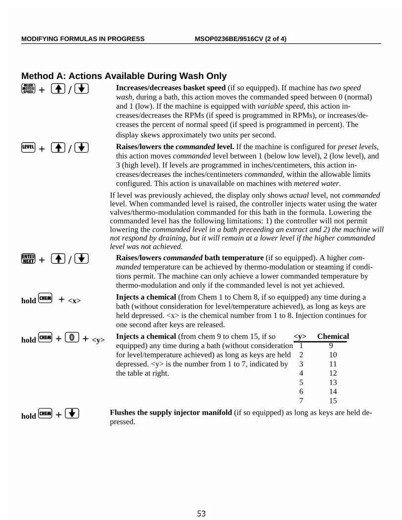
Method A: Actions Available During Wash Only
+ / Increases/decreases basket speed (if so equipped). If machine has two speedwash, during a bath, this action moves the commanded speed between 0 (normal)and 1 (low). If the machine is equipped with variable speed, this action in-creases/decreases the RPMs (if speed is programmed in RPMs), or increases/de-creases the percent of normal speed (if speed is programmed in percent). Thedisplay skews approximately two units per second.
+ / Raises/lowers the commanded level. If the machine is configured for preset levels,this action moves commanded level between 1 (below low level), 2 (low level), and3 (high level). If levels are programmed in inches/centimeters, this action in-creases/decreases the inches/centimeters commanded, within the allowable limits configured. This action is unavailable on machines with metered water.
If level was previously achieved, the display only shows actual level, not commanded level. When commanded level is raised, the controller injects water using the water
valves/thermo-modulation commanded for this bath in the formula. Lowering thecommanded level has the following limitations: 1) the controller will not permitlowering the commanded level in a bath preceeding an extract and 2) the machine willnot respond by draining, but it will remain at a lower level if the higher commanded level was not achieved.
+ / Raises/lowers commanded bath temperature (if so equipped). A higher com-manded temperature can be achieved by thermo-modulation or steaming if condi-tions permit. The machine can only achieve a lower commanded temperature bythermo-modulation and only if the commanded level is not yet achieved.
hold + <x> Injects a chemical (from Chem 1 to Chem 8, if so equipped) any time during abath (without consideration for level/temperature achieved), as long as keys areheld depressed. <x> is the chemical number from 1 to 8. Injection continues forone second after keys are released.
hold + + <y> Injects a chemical (from chem 9 to chem 15, if soequipped) any time during a bath (without considerationfor level/temperature achieved) as long as keys are held depressed. <y> is the number from 1 to 7, indicated by the table at right.
<y> Chemical1 9 2 103 114 125 136 147 15
hold + Flushes the supply injector manifold (if so equipped) as long as keys are held de-pressed.
MODIFYING FORMULAS IN PROGRESS MSOP0236BE/9516CV (2 of 4)
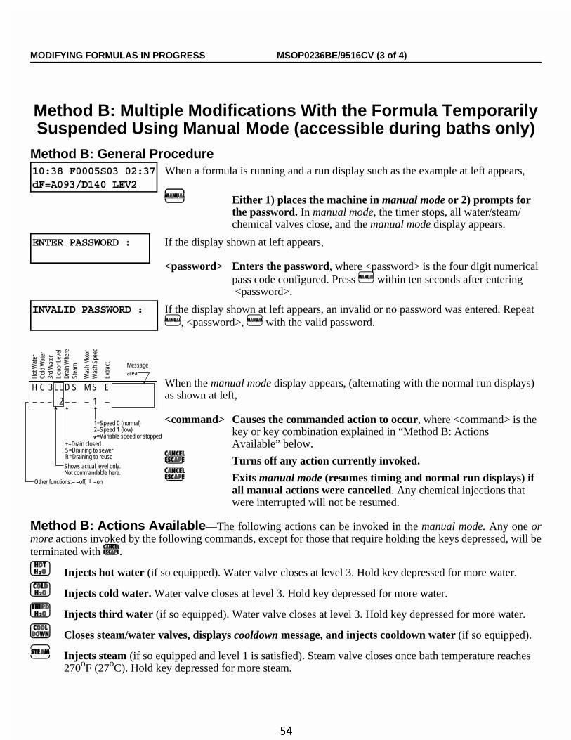
Method B: Multiple Modifications With the Formula TemporarilySuspended Using Manual Mode (accessible during baths only)
Method B: General Procedure10:38 F0005S03 02:37dF=A093/D140 LEV2
When a formula is running and a run display such as the example at left appears,
Either 1) places the machine in manual mode or 2) prompts forthe password. In manual mode, the timer stops, all water/steam/chemical valves close, and the manual mode display appears.
ENTER PASSWORD : If the display shown at left appears,
<password> Enters the password, where <password> is the four digit numericalpass code configured. Press within ten seconds after entering <password>.
INVALID PASSWORD : If the display shown at left appears, an invalid or no password was entered. Repeat, <password>, with the valid password.
When the manual mode display appears, (alternating with the normal run displays)as shown at left,
<command> Causes the commanded action to occur, where <command> is thekey or key combination explained in “Method B: ActionsAvailable” below.
Turns off any action currently invoked.
Exits manual mode (resumes timing and normal run displays) ifall manual actions were cancelled. Any chemical injections thatwere interrupted will not be resumed.
Method B: Actions Available—The following actions can be invoked in the manual mode. Any one ormore actions invoked by the following commands, except for those that require holding the keys depressed, will beterminated with .
Injects hot water (if so equipped). Water valve closes at level 3. Hold key depressed for more water.
Injects cold water. Water valve closes at level 3. Hold key depressed for more water.
Injects third water (if so equipped). Water valve closes at level 3. Hold key depressed for more water.
Closes steam/water valves, displays cooldown message, and injects cooldown water (if so equipped).
Injects steam (if so equipped and level 1 is satisfied). Steam valve closes once bath temperature reaches270oF (27oC). Hold key depressed for more steam.
+=Drain closedS=Draining to sewerR=Draining to reuse
Shows actual level only.Not commandable here.
Other functions: =off, + =on
H C 3
2 1
LL D S M S E
Hot
Wat
erC
old
Wat
er3r
d W
ater
Liqu
or L
evel
Dra
in W
here
Stea
m
Was
h M
otor
Was
h Sp
eed
Extra
ct Messagearea
1=Speed 0 (normal)2=Speed 1 (low)=Variable speed or stopped*
MODIFYING FORMULAS IN PROGRESS MSOP0236BE/9516CV (3 of 4)

Closes water/steam/chemical valves, disables reuse drain (if equipped), and drains bath to sewer.
Disables sewer drain, closes water/steam/chemical valves, and drains bath to reuse (if so equipped).
Turns the wash motor on. Motor starts with a delay, but powers off instantly with brake not applied.
Displays basket speed (if equipped with two-speed or variable speed wash).
+ / Increases/decreases basket speed as explained in method A.
+ If level 2 is satisfied, drains to sewer and either 1) accelerates to extract speed, or 2)prompts for an extract speed (if two-speed extract).
+ If level 2 is satisfied, drains to reuse (if so equipped) and either 1) accelerates to extractspeed, or 2) prompts for an extract speed (if two-speed extract).
HC3LLDS MS E EXTRACT---02*- -* - 0=L 1=H
If the extract speed prompt shown in the message area of the manual mode display atleft appears,
<x> Accelerates to the commanded extract speed if level 2 is satisfied,where <x> is 0 (low extract) or 1 (high extract).
hold + <x> Injects a chemical (from chem 1 to chem 8, if so equipped) as long as keys are held de-pressed, where <x> is the chemical number.
hold + + <y> Injects a chemical (from chem 9 through chem 15, ifso equipped), where <y> is the number from 1 through 7 indicated by the table at right.
<y> Chemical1 9 2 103 114 125 136 147 15
hold + Flushes the supply injector manifold (if so equipped) as long as the keys are held de-pressed.
Using Formula 99 to Develop/Test a New FormulaFormula 99 is a 63.75 minute bath with no water or any other functions and with the cylinder stopped. To
develop/test a process without programming a new formula, run Formula 99 and use the “Method B” proceduresdescribed herein.
NOTE 1: Formula 99 is available provided the machine is not on line to Mildata®.
NOTE 2: Even if the password is enabled, the controller permits modifying Formula 99 without the pass-word. However, Formula 99 cannot be copied, deleted, or permanently changed.
MODIFYING FORMULAS IN PROGRESS MSOP0236BE/9516CV (4 of 4)

Section 4Troubleshooting
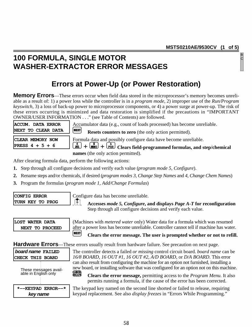
MSTS0210AE/9530CV (1 of 5)
100 FORMULA, SINGLE MOTORWASHER-EXTRACTOR ERROR MESSAGES
Errors at Power-Up (or Power Restoration)Memory Errors —These errors occur when field data stored in the microprocessor’s memory becomes unreli-able as a result of: 1) a power loss while the controller is in a program mode, 2) improper use of the Run/Programkeyswitch, 3) a loss of back-up power to microprocessor components, or 4) a power surge at power-up. The risk ofthese errors occurring is minimized and data restoration is simplified if the precautions in “IMPORTANTOWNER/USER INFORMATION . . .” (see Table of Contents) are followed.
ACCUM. DATA ERRORNEXT TO CLEAR DATA
Accumulator data (e.g., count of loads processed) has become unreliable.
Resets counters to zero (the only action permitted).
CLEAR MEMORY NOW PRESS 4 + 5 + 6
Formula data and possibly configure data have become unreliable.
+ + Clears field-programmed formulas, and step/chemicalnames (the only action permitted).
After clearing formula data, perform the following actions:
1. Step through all configure decisions and verify each value (program mode 5, Configure).
2. Rename steps and/or chemicals, if desired (program modes 3, Change Step Names and 4, Change Chem Names)
3. Program the formulas (program mode 1, Add/Change Formulas)
CONFIG ERROR TURN KEY TO PROG
Configure data has become unreliable.
Accesses mode 5, Configure, and displays Page A-T for reconfiguration Step through all configure decisions and verify each value.
LOST WATER DATANEXT TO PROCEED
(Machines with metered water only) Water data for a formula which was resumedafter a power loss has become unreliable. Controller cannot tell if machine has water.
Clears the error message. The user is prompted whether or not to refill.
Hardware Errors —These errors usually result from hardware failure. See precaution on next page.
board name FAILEDCHECK THIS BOARD
The controller detects a failed or missing control circuit board. board name can be16/8 BOARD, 16 OUT #1, 16 OUT #2, A/D BOARD, or D/A BOARD. This errorcan also result from configuring the machine for an option not furnished, installing anew board, or installing software that was configured for an option not on this machine.
Clears the error message, permitting access to the Program Menu. It alsopermits running a formula, if the cause of the error has been corrected.
*--KEYPAD ERROR--*key name
The keypad key named on the second line shorted or failed to release, requiringkeypad replacement. See also display freezes in “Errors While Programming.”
These messages avail-able in English only
BC

Errors While OperatingPRECAUTION: Before troubleshooting operating errors, review safety instructions in all applicablemanuals.
Errors That Disable the Three-Wire Circuit(Immediately Stops All Machine Functions) —The three-wire relay provides control circuit powerto the machine. Once energized by momentarily depressing the Start button, the three-wire relay is held energizedby its own normally open contact, in series with numerous other safety devices (e.g., motor overloads, tilt limitswitches, door interlock). Should any of these contacts open, even momentarily, all machine functions stop imme-diately, inlet valves close, the drain opens, the operator alarm sounds, and the appropriate error message appears.
3 WIRE DISABLEDFAULT : message
The three-wire relay became de-energized for the reason indicated by message.
Resumes the cycle (or enables the three-wire circuit), clears the errormessage, and silences the operator alarm, providing the cause of the errorhas been corrected.
Message ExplanationDOOR Door interlock relay indicates door is or was open.WASH OVERLOAD Wash motor overload opened.VARIABLE SPEED Variable speed drive unit malfunctioned. Check the variable speed drive unit display
for an error code and refer to the manual for this unit.DRAIN OVERLOAD Drain motor overload opened.E1 OVERLOAD E1 (low-speed extract) motor overload opened.E2 OVERLOAD E2 (high-speed extract) motor overload opened.FRONT UP Front of machine not full down, or front down switch, relay, or circuitry malfunctioned.REAR UP Rear of machine not full down, or rear down switch, relay, or circuitry malfunctioned.SEE MANUAL The controller cannot determine why the three-wire relay opened. Most often, this is the
result of pressing a Stop button. Otherwise, see three-wire circuit in schematic manual.
BRAKE FAULT MUST BECLEARED TO RESTART
Brake pressure switch detects insufficient air pressure in the brake release air cylin-der to guarantee brake has released. Possible causes include low air pressure, aleaking air cylinder piston cup, pinched or leaking air lines, a leaking quick-re-lease air valve, or a faulty pressure switch or pilot air valve. On Hydro-Cushion®
models, low air pressure can result from an air line that is too small to handle thepushdown and the brake, which operate simultaneously.
board name FAILEDCHECK THIS BOARD
The controller detects a failed or missing control circuit board. See “Hardware Er-rors” under “Errors At Power-Up . . .” in this section.
These messages avail-able in English only
100 FORMULA, SINGLE MOTORWASHER-EXTRACTOR ERROR MESSAGES MSTS0210AE/9530CV (2 of 5)
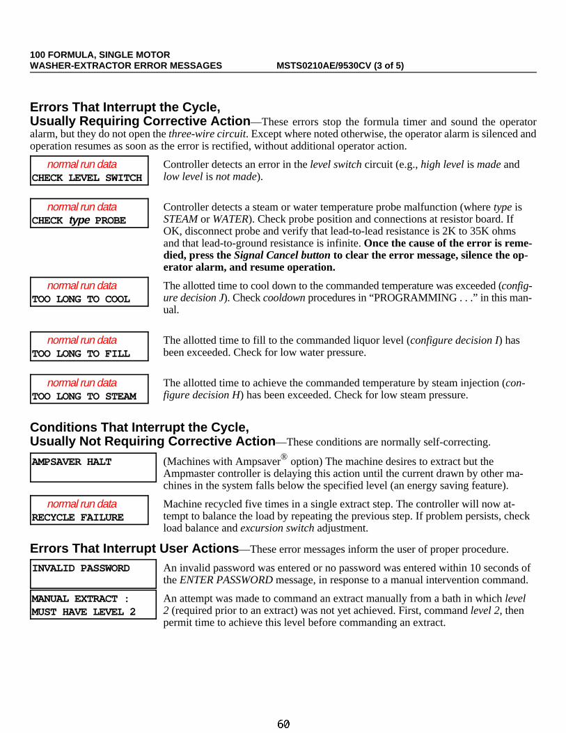
Errors That Interrupt the Cycle, Usually Requiring Corrective Action —These errors stop the formula timer and sound the operatoralarm, but they do not open the three-wire circuit. Except where noted otherwise, the operator alarm is silenced andoperation resumes as soon as the error is rectified, without additional operator action.
normal run dataCHECK LEVEL SWITCH
Controller detects an error in the level switch circuit (e.g., high level is made andlow level is not made).
normal run dataCHECK type PROBE
Controller detects a steam or water temperature probe malfunction (where type isSTEAM or WATER). Check probe position and connections at resistor board. IfOK, disconnect probe and verify that lead-to-lead resistance is 2K to 35K ohmsand that lead-to-ground resistance is infinite. Once the cause of the error is reme-died, press the Signal Cancel button to clear the error message, silence the op-erator alarm, and resume operation.
normal run data TOO LONG TO COOL
The allotted time to cool down to the commanded temperature was exceeded (config-ure decision J). Check cooldown procedures in “PROGRAMMING . . .” in this man-ual.
normal run data TOO LONG TO FILL
The allotted time to fill to the commanded liquor level (configure decision I) hasbeen exceeded. Check for low water pressure.
normal run data TOO LONG TO STEAM
The allotted time to achieve the commanded temperature by steam injection (con-figure decision H) has been exceeded. Check for low steam pressure.
Conditions That Interrupt the Cycle, Usually Not Requiring Corrective Action —These conditions are normally self-correcting.
AMPSAVER HALT (Machines with Ampsaver® option) The machine desires to extract but theAmpmaster controller is delaying this action until the current drawn by other ma-chines in the system falls below the specified level (an energy saving feature).
normal run dataRECYCLE FAILURE
Machine recycled five times in a single extract step. The controller will now at-tempt to balance the load by repeating the previous step. If problem persists, checkload balance and excursion switch adjustment.
Errors That Interrupt User Actions —These error messages inform the user of proper procedure.
INVALID PASSWORD An invalid password was entered or no password was entered within 10 seconds ofthe ENTER PASSWORD message, in response to a manual intervention command.
MANUAL EXTRACT :MUST HAVE LEVEL 2
An attempt was made to command an extract manually from a bath in which level2 (required prior to an extract) was not yet achieved. First, command level 2, thenpermit time to achieve this level before commanding an extract.
100 FORMULA, SINGLE MOTORWASHER-EXTRACTOR ERROR MESSAGES MSTS0210AE/9530CV (3 of 5)
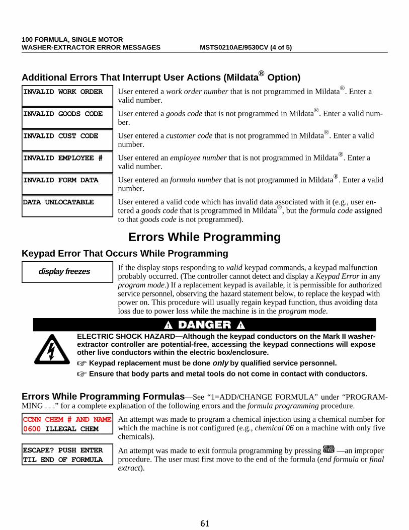
Additional Errors That Interrupt User Actions (Mildata ® Option)INVALID WORK ORDER User entered a work order number that is not programmed in Mildata®. Enter a
valid number.
INVALID GOODS CODE User entered a goods code that is not programmed in Mildata®. Enter a valid num-ber.
INVALID CUST CODE User entered a customer code that is not programmed in Mildata®. Enter a validnumber.
INVALID EMPLOYEE # User entered an employee number that is not programmed in Mildata®. Enter avalid number.
INVALID FORM DATA User entered an formula number that is not programmed in Mildata®. Enter a validnumber.
DATA UNLOCATABLE User entered a valid code which has invalid data associated with it (e.g., user en-tered a goods code that is programmed in Mildata®, but the formula code assignedto that goods code is not programmed).
Errors While ProgrammingKeypad Error That Occurs While Programming
display freezes If the display stops responding to valid keypad commands, a keypad malfunctionprobably occurred. (The controller cannot detect and display a Keypad Error in anyprogram mode.) If a replacement keypad is available, it is permissible for authorizedservice personnel, observing the hazard statement below, to replace the keypad withpower on. This procedure will usually regain keypad function, thus avoiding dataloss due to power loss while the machine is in the program mode.
ELECTRIC SHOCK HAZARD—Although the keypad conductors on the Mark II washer-extractor controller are potential-free, accessing the keypad connections will exposeother live conductors within the electric box/enclosure.☞ Keypad replacement must be done only by qualified service personnel.☞ Ensure that body parts and metal tools do not come in contact with conductors.
Errors While Programming Formulas —See “1=ADD/CHANGE FORMULA” under “PROGRAM-MING . . .” for a complete explanation of the following errors and the formula programming procedure.
CCNN CHEM # AND NAME0600 ILLEGAL CHEM
An attempt was made to program a chemical injection using a chemical number forwhich the machine is not configured (e.g., chemical 06 on a machine with only fivechemicals).
ESCAPE? PUSH ENTERTIL END OF FORMULA
An attempt was made to exit formula programming by pressing —an improperprocedure. The user must first move to the end of the formula (end formula or finalextract).
100 FORMULA, SINGLE MOTORWASHER-EXTRACTOR ERROR MESSAGES MSTS0210AE/9530CV (4 of 5)

FORM xx INCOMPLETETURN KEY TO PROG
An attempt was made to exit formula programming by turning the keyswitch to Runwithout first returning to the Program Menu. This is an improper procedure whichcauses the data for formula xx to become unreliable. xx is the formula number.
Deletes the incomplete formula. If no other memory errors are detected, thecontroller permits returning to the run mode.
Fxx TMMQCCCHC LSSyy ILLEGAL INSERT!
An attempt was made to duplicate this step when this would result in an illegal con-dition (e.g., adjacent extract steps or two end formula steps). xx and yy are the for-mula and step numbers, respectively.
Fxx TMMQCCCHC LSSyy ILLEGAL DELETE!
An attempt was made to delete this step when this would result in an illegal condi-tion (e.g., adjacent extract steps).
Fxx COOLDOWN ILLEGALSyy PRESS NEXT
An attempt was made to create a cooldown step when the prerequisites are not met.Prerequisites are: 1) cooldown is configured (configure decision J), 2) the cool-down is not the first step in a program, and 3) the preceding step is not an extract.
MEMORY IS FULLPRESS NEXT
Formula memory will be exceeded with the next step, so this formula must be deleted.
Deletes this incomplete formula.
Errors While Configuring —See “5=CONFIGURE” under “PROGRAMMING . . .” for a complete expla-nation of the configuration procedure.
ESCAPE? GO TO ENDOF CONFIGURATION
An attempt was made to exit the configure mode by pressing —an improperprocedure. Once in this mode the user must move through all decisions, whether ornot they are to be changed.
Errors While Downloading —See “6=DOWNLOAD” under “PROGRAMMING . . .” for a complete ex-planation of the following errors and the download procedure.
DOWN LOAD ABORTEDNEXT TO PROCEED
The user manually aborted the download on this machine, or on the sending ma-chine, if this is a receiving machine.
ERROR IN CHECK SUMNEXT TO PROCEED
This receiving machine received unreliable data, possibly due to a bad connectionin the serial link. Repeat the download once the problem is corrected.
[S] 9600 BAUD 000WAITING FOR MASTER
If this display appears after downloading has begun, this receiving machine is notreceiving data, possibly due to a bad connection in the serial link. Repeat the down-load once the problem is corrected.
100 FORMULA, SINGLE MOTORWASHER-EXTRACTOR ERROR MESSAGES MSTS0210AE/9530CV (5 of 5)

MSOP0267AE/9530DV (1 of 5)
MONITORING INPUTS AND OUTPUTSFOR MARK II AND III FxW WASHER-EXTRACTORS
This section identifies all inputs and outputs used in the Mark II and III FxW washer-extractor controller. Italso demonstrates how to access RPM information during operation. The current state of all inputs (made or notmade) and the current state of most outputs (energized or not energized) can be displayed while a formula is runningor stopped due to an error condition. This is real-time information. Any change in the state of the input or output isdisplayed as it occurs.
NOTE: See “MANUAL MODE MENU FUNCTIONS . . .” (see Table of Contents) for instructions ontesting outputs and viewing inputs while the machine is idle.
C
D

Inputs10:38 F0005S03 02:37dF=A093/D140 LEV2
When a formula is running and a normal run display or error display similar tothe displays at left appears,
3 WIRE DISABLEDFAULT : SEE MANUAL
hold Displays the first 16 inputs: (0) A through P.
hold + Displays the second 16 inputs: (1) A through P.
When the input status display appears as in the example at left, see the “Tableof Inputs” below, for input descriptions.
Table of InputsDisplayCode
(0) A through P(direct inputs -processor board)
(1) A through P(8/16 Board #1)
Input Name Connector/Pin Input Name Connector/PinA — — Tank is Full (Drain to Sewer) 1MTA3-10
B — — Door Closed 1MTA3-9
C — — Inverter Tripped 1MTA3-8
D — — — —
E — — — —
F — — — —
G — — Don’t Allow Chems 1MTA3-2
H — — — —
I Mildata MTA38-8 Amp Saver 1MTA4-10
J Program key MTA38-3 — —
K Signal cancel MTA38-2 — —
L Course Balance MTA 38-5 — —
M Excursion MTA38-6 — —
N Three wire MTA38-7 — —
O — — — —
P — — — —
NOTE: Once the drain to sewer input (1MTA3-10) is made, the input is latched and the machine drains tothe sewer until the drain cycle is over (even if the input is lost before then). The latch resets before the nextdrain cycle.
B
C
MONITORING INPUTS AND OUTPUTSFOR MARK II AND III FxW WASHER-EXTRACTORS MSOP0267AE/9530DV (2 of 5)

Outputs10:38 F0005S03 02:37dF=A093/D140 LEV2
When a formula is running and a normal run display or error display similar tothe displays at left appears,
3 WIRE DISABLEDFAULT : SEE MANUAL
hold Displays the first 16 outputs: (0) a through p.
hold + Displays the second 16 outputs: (1) a through p.
hold + Displays the third 16 outputs: (2) a through p.
When the output status display appears as in the example at left, see the follow-ing tables of outputs for output descriptions.
Table of First 16 Outputs: (0) a through pDis-playCode
Output Name Connector/PinCommon Normally Open
On 8/16 Board #1a Recirculation Pump 1MTA5-9 1MTA5-8 1MTA5-10
b Cooldown 1MTA5-6 1MTA5-5 1MTA5-7
c Flush 1MTA5-4 1MTA5-3 1MTA5-1
d Chem 4 1MTA5-2 1MTA6-10 1MTA6-3
e Chem 1 1MTA6-1 1MTA6-2 N/A
f Chem 3 1MTA6-4 1MTA6-5 N/A
g Chem 2 1MTA6-6 1MTA6-7 N/A
h Chem 5 1MTA6-8 1MTA6-9 N/A
On 16 Out Board #1i Tank to Machine 1MTA13-9 1MTA13-8 1MTA13-10
j Alternate Acelerate/Decelerate 1MTA13-6 1MTA13-5 1MTA13-7
k Machine to Machine 1MTA13-3 1MTA13-4 1MTA14-10
l CW Wash 1MTA13-1 1MTA13-2 1MTA15-10
m CCW Wash 1MTA14-8 1MTA14-7 1MTA14-9
n Steam Valve 1MTA14-5 1MTA14-6 N/A
o Signal 1MTA14-3 1MTA14-4 N/A
p Three Wire Relay 1MTA14-1 1MTA14-2 N/A
MONITORING INPUTS AND OUTPUTSFOR MARK II AND III FxW WASHER-EXTRACTORS MSOP0267AE/9530DV (3 of 5)

Table of Second 16 Outputs: (1) a through hDis-playCode
Output Name Connector/PinCommon Normally Open Normally Closed
On 16 Out Board#1a — — — —b Water Valve #1 1MTA15-5 1MTA15-6 N/Ac Water Valve #2 1MTA15-3 1MTA15-4 N/Ad Water Valve #3 1MTA15-1 1MTA15-2 N/Ae Sewer Drain 1MTA16-7 1MTA16-8 N/Af Reuse Drain 1MTA16-5 1MTA16-6 N/Ag Door Unlock 1MTA16-3 1MTA16-4 N/Ah Machine to Tank 1MTA16-1 1MTA16-2 N/A
i-p — — — —
Table of Third 16 Outputs: (2) a through pDis-playCode
Output Name Connector/PinCommon Normally
OpenNormally Closed
On 16 Out Board #2a Chem 14 2MTA13-1 2MTA13-11 2MTa13-10
b Chem 9 2MTA13-2 2MTA13-12 2MTA13-7
c Chem 13 2MTA13-3 2MTA13-13 2MTA14-10
d Flush 2MTA13-4 2MTA13-14 2MTA15-10
e Chem 15 2MTA13-5 2MTA13-15 2MTA14-9
f Chem 11 2MTA13-6 2MTA13-16 N/A
g Chem Save 2MTA13-7 2MTA13-17 N/A
h Drain Save (Miltrench) 2MTA13-8 2MTA13-18 N/A
i Chem 10 2MTA13-9 2MTA13-19 N/A
j Amp Saver 2MTA13-10 2MTA14-1 N/A
k Chem 6 2MTA14-11 2MTA14-2 N/A
l Chem 7 2MTA14-12 2MTA14-3 N/A
m Chem 8 2MTA14-4 2MTA14-13 N/A
n Chem 12 2MTA14-4 2MTA14-14 N/A
o — — — —
p — — — —
C
MONITORING INPUTS AND OUTPUTSFOR MARK II AND III FxW WASHER-EXTRACTORS MSOP0267AE/9530DV (4 of 5)

RPM Display10:38 F0005S03 02:37dF=A093/D140 LEV2
When a bath, drain, or extract is running as shown at left,
10:38 F0005S03 02:374000 0025RPM
Displays the speed value and machine RPM. The speed value isa numerical representation of of the analog voltage to the variablespeed controller (i.e., 0000=0 volts and 4095=10 volts).
Returns to the run display.
C
MONITORING INPUTS AND OUTPUTSFOR MARK II AND III FxW WASHER-EXTRACTORS MSOP0267AE/9530DV (5 of 5)

MSOP0267BE/9711BV (1 of 6)
MONITORING MICROPROCESSOR INPUTS AND OUTPUTSFOR THE MARK IV AND V 100 FORMULA, SINGLE MOTORWASHER-EXTRACTORS
This section identifies all inputs and outputs used in the Mark IV and V microprocessor 100 formula, singlemotor washer-extractor controller. It also demonstrates how to access RPM information during operation. The cur-rent state of all inputs (made or not made) and the current state of most outputs (energized or not energized) can bedisplayed while a formula is running or stopped due to an error condition. This is real-time information. Anychange in the state of the input or output is displayed as it occurs.
NOTE: See “MANUAL MODE MENU FUNCTIONS . . .” (see Table of Contents) for instructions ontesting outputs and viewing inputs while the machine is idle.

Inputs10:38 F0005S03 02:37dF=A093/D140 LEV2
When a formula is running and a normal run display or error display similar tothe displays at left appears,
3 WIRE DISABLEDFAULT : SEE MANUAL
hold Displays the first 16 inputs: (0) A through P.
hold + Displays the second 16 inputs: (1) A through P.
When the input status display appears as in the example at left, see the “Tableof Inputs” below, for input descriptions.
Table of InputsDisplayCode
(0) A through P(direct inputs -processor board)
(1) A through P(8/16 Board #1)
Input Name Connector/Pin Input Name Connector/PinA Mildata MTA38-8 Tank is Full (Drain to Sewer) 1MTA4-1
B Program Key MTA38-3 1MTA4-2
C Signal cancel MTA38-2 Inverter Tripped 1MTA4-3
D Course Balance MTA38-5 — —
E Excursion MTA38-6 — —
F Three wire MTA38-7 — —
G — — Don’t Allow Chems 1MTA4-7
H — — — —
I — — Amp Saver 1MTA4-11
J Drain Saver (Miltrench) MTA39-6 — —
K — — — —
L — — I am spotted 1MTA39-4
M — — — —
N — — — —
O — — — —
P — — — —
NOTE: Once the drain to sewer input (1MTA3-10) is made, the input is latched and the machine drains tothe sewer until the drain cycle is over (even if the input is lost before then). The latch resets before the nextdrain cycle.
MONITORING MICROPROCESSOR INPUTS AND OUTPUTS FOR THE MARK IV ANDV 100 FORMULA, SINGLE MOTOR WASHER-EXTRACTORS MSOP0267BE/9711BV (2 of 6)

Table of Inputs continued(2) A through P (8/16 Board #2)—StaphGuard Only
DisplayCode
Input Name Connector/Pin DisplayCode
Input Name Connector/Pin
A I Want Clean Control 2MTA4-1 I — —
B Autospot Desired 2MTA4-2 J — —
C — — K — —
D — — L — —
E — — M — —
F — — N — —
G — — O — —
H — — P — —
NOTE: The #3 Input/output board is a special peripheral board dedicated to the autospot feature. Becauseit does not communicate with the machine’s processor board, these inputs cannot be displayed. The inputsconnectors are as follows: Autospot Desired: 3MTA4-12, I Am Spotted: 3MTA4-3.
Outputs10:38 F0005S03 02:37dF=A093/D140 LEV2
When a formula is running and a normal run display or error display similar tothe displays at left appears,
3 WIRE DISABLEDFAULT : SEE MANUAL
hold Displays the first 16 outputs: (0) a through p.
hold + Displays the second 16 outputs: (1) a through p.
hold + Displays the third 16 outputs: (2) a through p.
When the output status display appears as in the example at left, see the follow-ing tables of outputs for output descriptions.
B
MONITORING MICROPROCESSOR INPUTS AND OUTPUTS FOR THE MARK IV ANDV 100 FORMULA, SINGLE MOTOR WASHER-EXTRACTORS MSOP0267BE/9711BV (3 of 6)
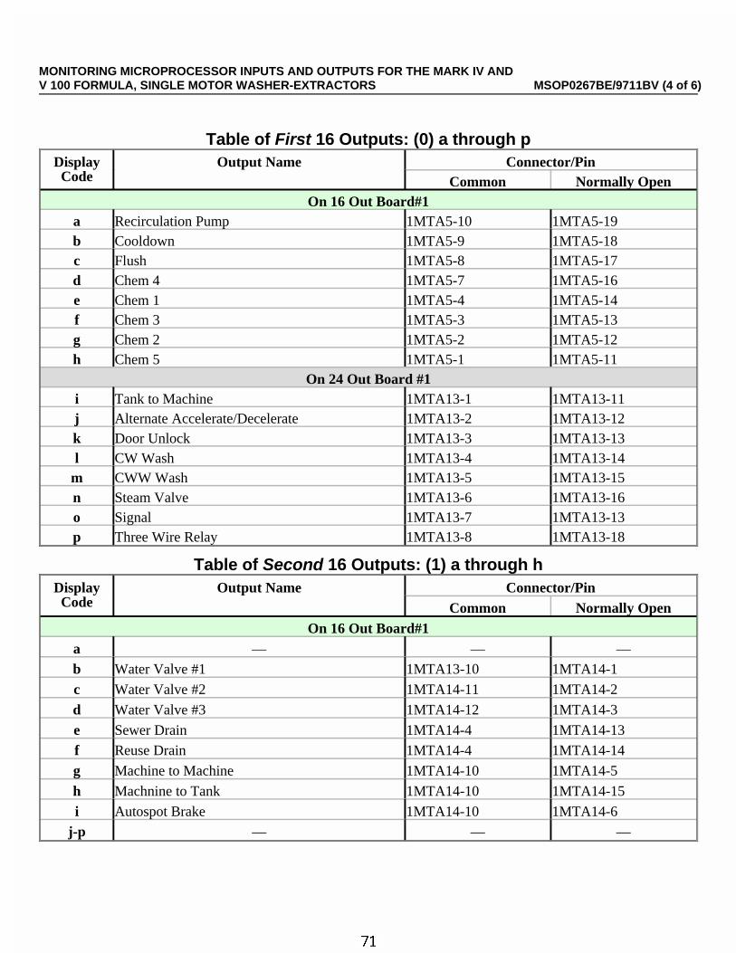
Table of First 16 Outputs: (0) a through pDisplayCode
Output Name Connector/PinCommon Normally Open
On 16 Out Board#1a Recirculation Pump 1MTA5-10 1MTA5-19b Cooldown 1MTA5-9 1MTA5-18c Flush 1MTA5-8 1MTA5-17d Chem 4 1MTA5-7 1MTA5-16e Chem 1 1MTA5-4 1MTA5-14f Chem 3 1MTA5-3 1MTA5-13g Chem 2 1MTA5-2 1MTA5-12h Chem 5 1MTA5-1 1MTA5-11
On 24 Out Board #1i Tank to Machine 1MTA13-1 1MTA13-11j Alternate Accelerate/Decelerate 1MTA13-2 1MTA13-12k Door Unlock 1MTA13-3 1MTA13-13l CW Wash 1MTA13-4 1MTA13-14
m CWW Wash 1MTA13-5 1MTA13-15n Steam Valve 1MTA13-6 1MTA13-16o Signal 1MTA13-7 1MTA13-13p Three Wire Relay 1MTA13-8 1MTA13-18
Table of Second 16 Outputs: (1) a through hDisplayCode
Output Name Connector/PinCommon Normally Open
On 16 Out Board#1a — — —
b Water Valve #1 1MTA13-10 1MTA14-1
c Water Valve #2 1MTA14-11 1MTA14-2
d Water Valve #3 1MTA14-12 1MTA14-3
e Sewer Drain 1MTA14-4 1MTA14-13
f Reuse Drain 1MTA14-4 1MTA14-14
g Machine to Machine 1MTA14-10 1MTA14-5
h Machnine to Tank 1MTA14-10 1MTA14-15
i Autospot Brake 1MTA14-10 1MTA14-6
j-p — — —
MONITORING MICROPROCESSOR INPUTS AND OUTPUTS FOR THE MARK IV ANDV 100 FORMULA, SINGLE MOTOR WASHER-EXTRACTORS MSOP0267BE/9711BV (4 of 6)
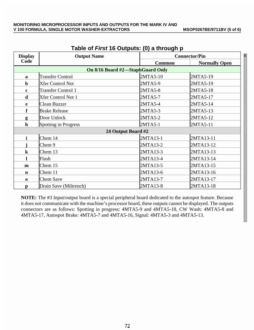
Table of First 16 Outputs: (0) a through pDisplayCode
Output Name Connector/PinCommon Normally Open
On 8/16 Board #2—StaphGuard Onlya Transfer Control 2MTA5-10 2MTA5-19b Xfer Control Not 2MTA5-9 2MTA5-19c Transfer Control 1 2MTA5-8 2MTA5-18d Xfer Control Not 1 2MTA5-7 2MTA5-17e Clean Buzzer 2MTA5-4 2MTA5-14f Brake Release 2MTA5-3 2MTA5-13g Door Unlock 2MTA5-2 2MTA5-12h Spotting in Progress 2MTA5-1 2MTA5-11
24 Output Board #2i Chem 14 2MTA13-1 2MTA13-11j Chem 9 2MTA13-2 2MTA13-12k Chem 13 2MTA13-3 2MTA13-13l Flush 2MTA13-4 2MTA13-14
m Chem 15 2MTA13-5 2MTA13-15n Chem 11 2MTA13-6 2MTA13-16o Chem Save 2MTA13-7 2MTA13-17p Drain Save (Miltrench) 2MTA13-8 2MTA13-18
NOTE: The #3 Input/output board is a special peripheral board dedicated to the autospot feature. Becauseit does not communicate with the machine’s processor board, these outputs cannot be displayed. The outputsconnectors are as follows: Spotting in progress: 4MTA5-9 and 4MTA5-18, CW Wash: 4MTA5-8 and4MTA5-17, Autospot Brake: 4MTA5-7 and 4MTA5-16, Signal: 4MTA5-3 and 4MTA5-13.
B
MONITORING MICROPROCESSOR INPUTS AND OUTPUTS FOR THE MARK IV ANDV 100 FORMULA, SINGLE MOTOR WASHER-EXTRACTORS MSOP0267BE/9711BV (5 of 6)

Table of Fourth 16 Outputs: (3) a through pDisplayCode
Output Name Connector/PinCommon Normally Open
24 Out Board #2 continueda Chem 10 2MTA13-9 2MTA13-19b Amp Saver 2MTA13-10 2MTA14-1c Chem 6 2MTA14-11 2MTA14-2d Chem 7 2MTA14-12 2MTA14-3e Chem 8 2MTA14-4 2MTA14-13f Chem 12 2MTA14-4 2MTA14-14g — — —h — — —
i-p — — —
RPM Display10:38 F0005S03 02:37dF=A093/D140 LEV2
When a bath, drain, or extract is running as shown at left,
10:38 F0005S03 02:374000 0025RPM
Displays the speed value and machine RPM. The speed value isa numerical representation of of the analog voltage to the variablespeed controller (i.e., 0000=0 volts and 4095=10 volts).
Returns to the run display.
MONITORING MICROPROCESSOR INPUTS AND OUTPUTS FOR THE MARK IV ANDV 100 FORMULA, SINGLE MOTOR WASHER-EXTRACTORS MSOP0267BE/9711BV (6 of 6)

MSOP0254BE/9514DV (1 of 8)
ÈMANUAL MODE MENU FUNCTIONS ONMARK II, III, IV, AND V WASHER-EXTRACTORS
This section describes functions on the Mark II, III, IV, and V microprocessor washer-extractor controllers(including outerwear machines) that are available when the machine is idle (formula not running) and in the runmode.
NOTE: See “MODIFYING FORMULAS IN PROGRESS” (see Table of Contents) for instructions onmanually modifying a running formula. See “MONITORING MICROPROCESSOR INPUTS AND OUT-PUTS . . .” for instructions on viewing inputs and outputs while the machine is running.
ÊSelections (Modes) on the Manual Menu0=Turn Output On —Actuate individual outputs for testing. This is called bare manual.1=Look at Inputs—View the on/off status of each input during idle conditions.2=Data Accumulation—View, print, and clear the accumulated counts of loads processed.
ÊTo Access the Manual MenuRUN FORMULA00 OR OK POWER OFF
When the Run Formula menu and selection 00 is displayed as shown at left,
Accesses the manual menu.
TURN OUTPUT ON0
When selection 0, Turn Output On, on the manual menu is displayed as shown,
/ Scrolls the available manual modes,or <x> Selects a manual mode, where <x> is a number from 0 to 2. See
the following information for how to access and utilize each manual mode.
or Returns to the Run Formula menu (run mode).
B
C

Ê0=Turn Output On (Bare Manual)ËHow Bare Manual Works —Bare manual permits turning certain outputs on and off, one at a time, for test-ing, when the machine is idle. Note that outputs appear in a different order on the bare manual menu herein, thanon the output status displays (see “MONITORING MICROPROCESSOR INPUTS AND OUTPUTS . . .”).
ËTo Actuate Outputs in Bare ManualTURN OUTPUT ON0
When selection 0, Turn Output On on the manual menu is displayed as shown,
Accesses mode 0 and displays Press Start.
Closes the three-wire circuit permitting output actuation and dis-plays the bare manual menu.
ABORT MANUAL OPER00
When selection 00 on the bare manual menu is displayed, as shown at left,
/ Scrolls the outputs.or <xx> Selects an output by number, where <xx> is a menu item number on
the “Table of Bare Manual Outputs.”
or Returns to the Run Formula menu.
COUNTER CLOCKWISE02
When an output is selected as in the example 02, Counter Clockwise, at left,
Turns the output on. See table for consequences.
Turns the output off and permits selecting any other output for testing.
ÏTable of Bare Manual Outputsfor 100-Formula, Multi-motor Washer-Extractor Controller
MenuItem
Output Nameon Display
ApplicableMachines
Standardor Option
Consequences of Actuating the Output
00 Abort Manual Oper all S Return to Run Formula menu.01 Clockwise all S Turn basket clockwise at wash speed.02 Counter Clockwise all S Turn basket counterclockwise at wash speed.03 Drain Speed all S Turn basket at drain speed (clockwise).04 Clutch 1 all S Clutch is normally engaged when Master switch is on.
Clutch disengages when this output is turned on then off.05 Water Valve #1 all S Opens valve.06 Water Valve #2 all S Opens valve.07 Water Valve #3 all O Opens valve.08 Sewer Drain all S Output on closes drain.09 Reuse Drain all O Output on opens drain.10 Brake all S Output on releases brake.
11–15Chemical (1 thru 5) all S Operates selected chemical inject device.16–25Chemical (6 thru 15) all O Operates selected chemical inject device.
26 Steam all O Opens steam valve.27 Cooldown all O Opens cooldown valve.
MANUAL MODE MENU FUNCTIONS ONMARK II, III, IV, AND V WASHER-EXTRACTORS MSOP0254BE/9514DV (2 of 8)
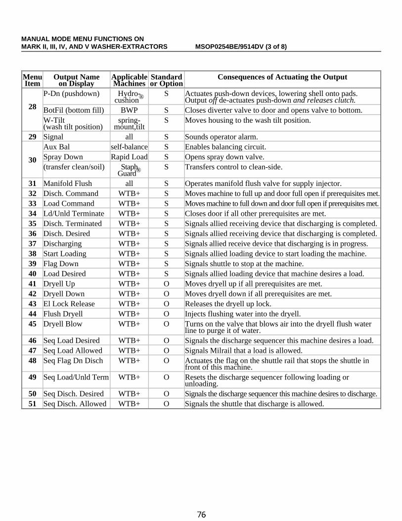
MenuItem
Output Nameon Display
ApplicableMachines
Standardor Option
Consequences of Actuating the Output
28
P-Dn (pushdown) Hydro-cushion®
S Actuates push-down devices, lowering shell onto pads.Output off de-actuates push-down and releases clutch.
BotFil (bottom fill) BWP S Closes diverter valve to door and opens valve to bottom.W-Tilt (wash tilt position)
spring-mount,tilt
S Moves housing to the wash tilt position.
29 Signal all S Sounds operator alarm.
30
Aux Bal self-balance S Enables balancing circuit.Spray Down Rapid Load S Opens spray down valve.(transfer clean/soil) Staph
Guard®S Transfers control to clean-side.
31 Manifold Flush all S Operates manifold flush valve for supply injector.32 Disch. Command WTB+ S Moves machine to full up and door full open if prerequisites met.33 Load Command WTB+ S Moves machine to full down and door full open if prerequisites met.34 Ld/Unld Terminate WTB+ S Closes door if all other prerequisites are met.35 Disch. Terminated WTB+ S Signals allied receiving device that discharging is completed.36 Disch. Desired WTB+ S Signals allied receiving device that discharging is completed.37 Discharging WTB+ S Signals allied receive device that discharging is in progress.38 Start Loading WTB+ S Signals allied loading device to start loading the machine.39 Flag Down WTB+ S Signals shuttle to stop at the machine.40 Load Desired WTB+ S Signals allied loading device that machine desires a load.41 Dryell Up WTB+ O Moves dryell up if all prerequisites are met.42 Dryell Down WTB+ O Moves dryell down if all prerequisites are met.43 El Lock Release WTB+ O Releases the dryell up lock.44 Flush Dryell WTB+ O Injects flushing water into the dryell.45 Dryell Blow WTB+ O Turns on the valve that blows air into the dryell flush water
line to purge it of water.46 Seq Load Desired WTB+ O Signals the discharge sequencer this machine desires a load.47 Seq Load Allowed WTB+ O Signals Milrail that a load is allowed.48 Seq Flag Dn Disch WTB+ O Actuates the flag on the shuttle rail that stops the shuttle in
front of this machine.49 Seq Load/Unld Term WTB+ O Resets the discharge sequencer following loading or
unloading.50 Seq Disch. Desired WTB+ O Signals the discharge sequencer this machine desires to discharge.51 Seq Disch. Allowed WTB+ O Signals the shuttle that discharge is allowed.
MANUAL MODE MENU FUNCTIONS ONMARK II, III, IV, AND V WASHER-EXTRACTORS MSOP0254BE/9514DV (3 of 8)

ÏTable of Bare Manual Outputsfor 100-Formula, Single Motor Washer-Extractor Controller
Menu Item
Output Nameon Display
Standardor Option
Consequences of Actuating the Output
00 Abort Manual Oper S Returns to run formula menu.
01 Clockwise S Turns basket clockwise at wash speed.
02 Counter Clockwise S Turns basket counterclockwise at wash speed.
03 Door Unlock S Unlocks door.
04 Water Valve #1 S Opens valve.
05 Water Valve #2 S Opens valve.
06 Water Valve #3 O Opens valve.
07 Sewer Drain S Output on closes drain.
08 Reuse Drain O Output on opens drain.
09 Brake S Not Used
10-14 Chemical (1 thru 5) S Operates selected chemical inject device.
15-24 Chemical (6 thru 15) O Operates selected chemical inject device.
25 Steam O Opens steam valve.
26 Cooldown O Opens cooldown valve.
27 Signal S Sounds operator alarm.
28 AlternateAccelerator/Decelerator
S Signals inverter for use;alternates acceleration or deceleration constants.
29 Manifold Flush S Operates manifold flush valve for supply injector.
30 Recirc. Pump O Enables recirculation pump.
31 Machine to Machine O Enables valve from machine to machine.
32 Machine to Tank O Enables valve from machine to tank.
33 Tank to Machine O Enables valve from tank to machine.
34 Transfer Control S Transfers machine control to clean side.
35 Brake Release S Releases autospot brake.
36 Clean Buzzer S Sounds the operator alarm on clean side.
D
D
D
MANUAL MODE MENU FUNCTIONS ONMARK II, III, IV, AND V WASHER-EXTRACTORS MSOP0254BE/9514DV (4 of 8)
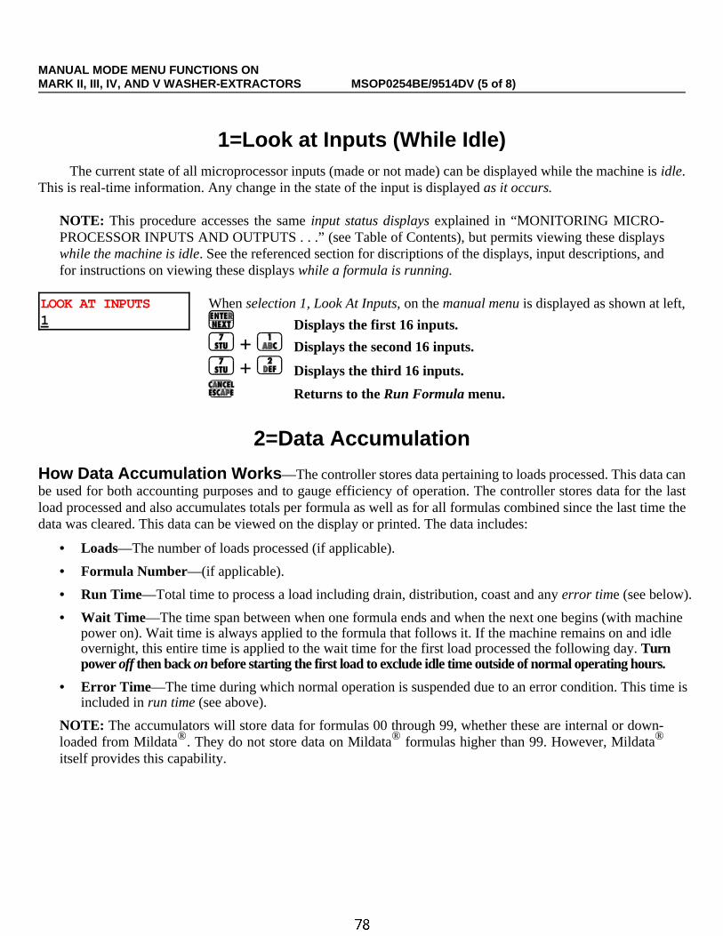
Ê1=Look at Inputs (While Idle)The current state of all microprocessor inputs (made or not made) can be displayed while the machine is idle.
This is real-time information. Any change in the state of the input is displayed as it occurs.
NOTE: This procedure accesses the same input status displays explained in “MONITORING MICRO-PROCESSOR INPUTS AND OUTPUTS . . .” (see Table of Contents), but permits viewing these displayswhile the machine is idle. See the referenced section for discriptions of the displays, input descriptions, andfor instructions on viewing these displays while a formula is running.
LOOK AT INPUTS1
When selection 1, Look At Inputs, on the manual menu is displayed as shown at left,
Displays the first 16 inputs.
+ Displays the second 16 inputs.
+ Displays the third 16 inputs.
Returns to the Run Formula menu.
Ê2=Data Accumulation
ËHow Data Accumulation Works —The controller stores data pertaining to loads processed. This data canbe used for both accounting purposes and to gauge efficiency of operation. The controller stores data for the lastload processed and also accumulates totals per formula as well as for all formulas combined since the last time thedata was cleared. This data can be viewed on the display or printed. The data includes:
• Loads—The number of loads processed (if applicable).
• Formula Number—(if applicable).
• Run Time—Total time to process a load including drain, distribution, coast and any error time (see below).
• Wait Time—The time span between when one formula ends and when the next one begins (with machinepower on). Wait time is always applied to the formula that follows it. If the machine remains on and idleovernight, this entire time is applied to the wait time for the first load processed the following day. Turnpower off then back on before starting the first load to exclude idle time outside of normal operating hours.
• Error Time —The time during which normal operation is suspended due to an error condition. This time isincluded in run time (see above).
NOTE: The accumulators will store data for formulas 00 through 99, whether these are internal or down-loaded from Mildata®. They do not store data on Mildata® formulas higher than 99. However, Mildata®
itself provides this capability.
MANUAL MODE MENU FUNCTIONS ONMARK II, III, IV, AND V WASHER-EXTRACTORS MSOP0254BE/9514DV (5 of 8)

ËSelections (Modes) on the Data Accumulation Sub-Menu
0=Display Data—Display accumulated data on the microprocessor display.1=Print—Print out hard copy of accumulated data on a serial printer.2=Clear—Erase all accumulated data.
ËTo Access the Data Accumulation MenuDATA ACCUMULATION2
When selection 2, Data Accumulation, on the manual menu is displayed as shownat left,
Accesses Data Accumulation and displays the choices.
0 0=DISPLAY DATA1=PRINT 2=CLEAR
When the Data Accumulation choices are displayed as shown at left,
/ Scrolls the choices.or <x> Selects one of the displayed choices, where <x> is a number from 0 to 2.
or Returns to the Run Formula menu (run mode).
Ë0=Display Data —Accumulated data may be displayed in three ways, as shown in the “Table of DisplayedData” below.
0 0=DISPLAY DATA1=PRINT 2=CLEAR
When 0=Display Data is chosen from the Data Accumulation choices, as shown atleft,
Accesses Display Data and displays the choices.
0 0=LAST LOAD1=FORMS 2=TOTAL
When the Display Data choices are displayed as shown at left,<x> Selects a type of data to display, where <x> is a number from 0 to 2.
Displays the selected data, as explained in the “Table of Displayed Data,” below.If 1=Forms is accessed,
/ Scrolls the formulas,or <xx> Selects a formula, where <xx> is the two-digit formula
number.
Returns to the Data Accumulation choices.
ÏTable of Displayed DataData Type:
0=LAST LOAD 1=FORMS (formulas) 2=TOTALData Displayed:
Formula 15
hours 1/10hour
Total number of loads run
hours 1/10hour
1/10 minute
Formula number of last load run
minuteshours1/10 hour
MANUAL MODE MENU FUNCTIONS ONMARK II, III, IV, AND V WASHER-EXTRACTORS MSOP0254BE/9514DV (6 of 8)

Ë1=Print —Accumulated data may be printed on a serial printer that conforms to the “REQUIREMENTS ANDSETTINGS FOR THE EPSON LX300 PRINTER” (see Table of Contents). FIGURE 1 is an example printout.
1 0=DISPLAY DATA1=PRINT 2=CLEAR
When 1=Print, is chosen from the Data Accumulation choices, as shown at left,
Accesses the print function and prompts for the date.
DATE: MM-DD-YYYYDATE: DD-MM-YYYY
00
When one of the date entry displays is displayed as shown at left,
<xx>, Enters the first value, where <xx> is the two-digit number for themonth or day (depending on the format configured) and advancesthe cursor to the second field.
<xx>, Enters the second value and advances the cursor to the third value.
<yyyy>, Enters the year, where <yyyy> is the four digit number for the yearand sends the data to the printer. When all data has been sent, the Data Accumulation menu reappears.
Month-day-year or day-month-year format, depend-ing on the format configured.
W/E: 48036QHP WASHER 06 VERSION 91000/S DATE: 11/09/1993 PAGE: 01
DATA ACCUMULATION
PELLERIN MILNOR CORPORATION
NOTES:
#HHTHHHTHHHHTMMT*
= Number= Hours-Hours-Tenth of hour= Hours-Hours-Hours-Tenth of hour= Hours-Hours-Hours-Hours-Tenth of hour= Minutes-Minutes-Tenth of minute= Data has reached maximum stored value.
0 = LAST FORMULA RUN
FORMULA RUN TIME WAIT TIME ERROR TIME#
05 003 001 000
HHT HHT MMT
1 = DATA PER FORMULA
FORMULA #OF LOADS RUN TIME WAIT TIME ERROR TIME# #
050911
042027008
037201830041
003800140026
002000000
HHHT HHHT HHT
2 = TOTAL ACCUMULATION DATA
TOTAL # OF LOADS RUN TIME WAIT TIME ERROR TIME#
0077 00596 00078 002
HHHHT HHHHT HHT
ÎFIGURE 1 (MSOP0254BE)
ÎExample Data Accumulation Printout
MANUAL MODE MENU FUNCTIONS ONMARK II, III, IV, AND V WASHER-EXTRACTORS MSOP0254BE/9514DV (7 of 8)

Ë2=Clear—Accumulated data may be cleared whenever the machine is idle. All data is cleared simultaneously.
2 0=DISPLAY DATA1=PRINT 2=CLEAR
When 2=Clear is chosen from the Data Accumulation choices as shown at left,
Accesses the clear function and prompts the user to continue or cancel.
NEXT TO CLEAR DATACANCEL=ESCAPE
When the display shown at left appears,
Clears all accumulated data from memory and returns to the Data Accumulation choices.
or Exits the clear function without clearing the accumulators and returns to the Data Accumulation choices.
MANUAL MODE MENU FUNCTIONS ONMARK II, III, IV, AND V WASHER-EXTRACTORS MSOP0254BE/9514DV (8 of 8)


Section 5Supplemental Information

N O T I C E
As this manual was being printed, Pellerin Milnor Corporation began amanufacturing change which may affect how this manual applies to yourmachine. The six-position DIP switch on each printed circuit board is beingreplaced with two sixteen-position rotary switches. The switches (DIP androtary) are used to set the logical address for each board that communicateswith the microprocessor in the machine, or with a higher-level control system(e.g., a Mildata network).
Because the change to rotary switches corresponds so closely to the release ofthis manual, we are supplying you with documentation on how to set bothtypes of switches.
If your machine uses printed circuit boards containing one DIP switch, referto MSFDA401DE to set the address on replacement boards. If your machineuses printed circuit boards containing rotary switches, refer to MSFDA401EE.
BMP970004/97071

PELLERIN MILNOR CORPORATION
BICMDF01 (Published) Book specs- Dates: 20050112 / 20050112 / 20050118 Lang: ENG01 Applic: CAU CM2 CM3 CGU CJU CKUCCN PDU YUU CPU CXU CSU CDU CWU
Hardware Components of Serial Microprocessor Controllers
1. GeneralMilnor® serial microprocessor controls are designed specifically for Milnor® machines andsystems. Along with certain external electromechanical relay logic and sensing devices, theycontrol all machine and system functions. Not every microprocessor controller includes all thecomponents described in this section.
2. Microprocessor ComponentsNote 1: This is a list of all components for Milnor® microprocessor controllers. Not every Milnor®
microprocessor controller includes all of the following components.
2.1. Keypad or Keyboard—Depending upon the model and type of machine, the keypad mayhave 12, 30, or 58 buttons. The different keypads are not interchangeable.
2.2. Keyswitch—Selects run/program modes. The key may be removed only when the switch is setto the Run position.
CAUTION 1 : Prevent Unauthorized Programming—To prevent unauthorizedprogramming, store the programming key so that it is not available to unauthorized personnel.Improper programming can damage equipment and goods.
2.3. Display—Depending upon the type and model of machine, the display may be either liquidcrystal, vacuum fluorescent, or cathode ray tube (CRT), which is a typical computer monitor.Different types of displays are not interchangeable.Liquid crystal graphic display—This display is identified by colored characters and graphics,
usually on a black or white background. It's currently used only on certain washer-extractormodels with the Milnor Mark VI control system.
Liquid crystal text display—This type of display is identified by dark gray characters on alighter gray background, or by green characters on a dark gray background.
Vacuum fluorescent display—The bright green characters on a black background make thisdisplay highly visible. This is the most common display for Milnor® washer-extractors, textilemachines, and dryers.
Cathode ray tube (CRT)—The CRT display resembles a television screen in appearance andfunction. This type of display is most commonly used in Miltrac™ and Mildata® systems,which require the display of graphics such as boxes and lines. It is also used on Milnor CBW®
tunnel washers.
2.4. Power Supply—The power supply converts the alternating current at the control circuitvoltage to direct current voltages of 12 volts positive and negative, and 5 volts positive. One ormore of these values are adjustable, depending on the specific power supply used in eachapplication.
The Milnor™ CBW® system employs two different power supplies to convert alternating currentfrom the control circuit to direct current for the microprocessor and peripheral boards.
2.4.1. Control Console Power Supply—The power supply referenced as ESPS in the schematic

Hardware Components of Serial Microprocessor Controllers
PELLERIN MILNOR CORPORATION
diagrams is a 40-watt power supply located in the Miltron™ or Mentor™ cabinet. It powers theperipheral boards located within this cabinet, including the optional load cell interface board andthe analog to digital board for a weighing conveyor, as well as the microprocessor board and thememory expansion board.
Tip: For maximum reliability and to minimize the chances of the processor board resetting due to lowvoltage, adjust the power supply voltage for 80186 processors to 5.10 VDC at the processorboard.
In systems operated via the Miltron™ controller, this power supply also provides electricity to themonitor interface board. In Mentor™-controlled tunnel systems, the monitor interface board iscontained within the Mentor™ computer enclosure and powered by the computer power supply.
2.4.2. Tunnel Power Supply—The power supply referenced as PSO in the schematic diagrams is a120-watt unit which powers the peripheral boards located on the tunnel washer. All threevoltages output by this device are adjustable.
If adjustment is necessary, set the 5 volts output to provide at least positive 4.8VDC at the electricbox on the module farthest from the power supply. This measurement must be made with anaccurate digital voltmeter. Verify that the positive and negative 12 volts outputs are set at positiveand negative 12.00VDC, respectively.
If the 5 volts reading at the peripheral board nearest the PSO power supply is at least positive5.25VDC, and the voltage at the peripheral board farthest from PSO is positive 4.8VDC or less,suspect one or more loose connections or inadequate wiring somewhere between the twoperipheral boards.
2.5. Power Supply —The power supply converts the alternating current at the control circuitvoltage to direct current voltages of 12 volts positive and negative, and 5 volts positive. One ormore of these values are adjustable, depending on the specific power supply used in eachapplication.
• The 12 volts positive is used to power all boards other than the microprocessor board. Thisvalue is not adjustable.
• The 12 volts negative is used by the analog to digital (A/D) board. This value is notadjustable.
• The 5 volts output powers the microprocessor. This value is adjustable and very sensitive. Fordevices using microprocessors other than the 80186, the power supply must be adjusted toprovide actual voltage of 4.95VDC to 5.10VDC at the microprocessor board. Use an accuratedigital voltmeter to measure this value. For devices with 80186 microprocessors, the powersupply voltage should be 5.10VDC at the processor board.
A wire of at least 14AWG (2.5 sq mm) must be connected between the ground points on themicroprocessor and the peripheral boards. This ground wire is installed at the factory if bothenclosures are mounted on the same machine (e.g., washer-extractors). The ground wire must beprovided during installation if the microprocessor enclosure and its associated peripheral boardenclosures are remote from one another (e.g., dryers).
Some machines, including Milnor® dryers, employ a second identical power supply to providepower for the peripheral boards, which are mounted in an enclosure separate from themicroprocessor enclosure.

PELLERIN MILNOR CORPORATION
2.6. Central Processing Unit (CPU) Board—Also referred to as the microprocessor, thecentral processing unit processes data received from the various inputs, stores information, andresponds to each keypad entry with the appropriate action. It may be mounted in an enclosureseparate from its peripheral boards. The CPU board contains EPROMs programmed by theMilnor® factory with fixed instructions (software) that determine how the machine functions.Depending upon machine model/type, the processor chip may one of three Intel models: the8085, the 8088, or the 80186.
Although the EPROMs do not require battery backup, the CPU board utilizes a battery whichnormally provides power to retain the user-programmable memory for two to three monthswithout external power.
2.7. Memory Expansion Board—Increases memory space available to the processor. Thisboard is used with 8088 CPU boards in some applications.
2.8. Battery—Provides memory retention backup when power is off. The battery is mounteddirectly on 8085 CPU boards, and mounted separately for 8088 and 80186 CPU boards. Acapacitor on the 8088 and 80186 CPU boards provides enough power to retain memory forseveral hours after the battery has been disconnected. Once fully charged, the battery backup isreliable for two to three months with no power applied.
2.9. Opto-Isolator Board—Optically isolates inputs to the microprocessor for electronic noiseimmunity. Opto-isolators are incorporated into the 8088 and 80186 CPU board; thus this separateboard is only required for machines employing Intel 8085 CPUs.
2.10. Input/Output Board—The 16/8 input-output board contains 16 solid-state signal inputdevices and eight output relays. The input devices are capable of faithfully conducting a low VA12VDC ground signal to the microprocessor. The output relays are socket-mounted SPDT,12VDC electromechanical relays with contacts capable of faithfully conducting a maximum of25VA at 110/120VAC (0.2 ampere or 200 milliamperes at 110/120VAC) or 12.5 VA at 24VAC(0.5 ampere or 500 milliamperes at 24VAC). The output will be either 24VAC or 110/120VAC,depending on the machine model/type.
These outputs and their power source are intended only to drive another relay with higher contactratings, that in turn may drive a pump, valve, solenoid, etc., from a separate power source. Neveruse these outputs to directly drive a pump, valve, or solenoid unless the maximum currentrequired never exceeds the above values. Higher ampere or VA loads will burn out traces on theprinted circuit board or possibly overload and damage the control circuit transformer.
This board has 25 status lights. The amber light flashes when the board is communicating. Eachof the 24 remaining lights represent an input (green lights) or output (red lights) on that board,and illuminates when the corresponding input or output is made. This board has two rotary dialswhich must be adjusted to set the board's address (see Section 4 “Assigning Board Addresses” inthis document). This board also has convenient test points that can be used to test voltage to theboard.Standard input/output board—used in all devices requiring input/output boards, except those
listed below.High-speed input/output board—used only in the following devices and configurations: E6N,
J6N, and T6N washer-extractors equipped with and configured for both variable basket speedand electronic balancing; Milrail configured for high-speed boards, and all configurations ofthe M7E centrifugal extractor.

Hardware Components of Serial Microprocessor Controllers
PELLERIN MILNOR CORPORATION
2.11. Output Board—A 24-output board contains 24 output relays identical to those described inSection 2.10 “Input/Output Board”.
2.12. Analog to Digital Convertor Board—Converts analog voltage signals, such astemperature, to a digital signal that can be utilized by the CPU. Up to a maximum of eightchannels may be provided on a single board. Although seemingly identical, the analog to digitalboards used to sense air temperature in the dryer, water temperature in washer-extractors andtextile machines, water temperature in the tunnel, and weight for a weighing conveyor are alldifferent. The different types are clearly marked with different part numbers, which arementioned in the wiring diagram set and are not interchangeable.
All analog to digital boards have one status light which flashes when the board is communicating.The board has two rotary dials which must be adjusted to set the board's address (see Section 4“Assigning Board Addresses”). This board also has convenient test points that can be used to testvoltage to the board.
2.13. Digital to Analog Convertor Board—Converts digital signals from the processor toanalog signals with voltages between 0 and 5VDC (e.g., provides the analog signal to the dryergas valve position actuator and dye machine steam position actuator).
This board has one status light which flashes when the board is communicating. The two rotarydials must be adjusted to set the board's address (see Section 4). This board also has convenienttest points that can be used to test voltage to the board.
2.14. CRT (Video Display) Board—Receives display instructions from the processor andgenerates the signals to the video monitor to create the desired displays; used in controllers suchas the Miltron™ and Miltrac™ controllers and Device Master™ systems.
CAUTION 2 : Avoid Component Damage—The CRT board can be installed backwards,even though the cabinet and bracketry makes this difficult, and labelling on the parent boardstates the proper orientation. Use care to orient the board correctly, otherwise microprocessorcomponents may be damaged.
CBW® systems with the Mentor™ controller use a standard computer video display adapter,housed within the Mentor™ computer, to transmit signals from the Mentor™ computer to thevideo monitor. Thus, Mentor™ systems do not have a separate video display board as describedhere.
2.15. Resistor Boards—Although visually similar, resistor boards vary according to theapplication. The different types are clearly marked with part numbers, which are mentioned inthe electrical schematic diagrams and are not interchangeable.For temperature-sensing systems—used with analog to digital boards in washer-extractors and
dye-extractors as part of temperature-sensing system; not required on tunnel systems becausethe necessary circuitry is included on other standard CBW® circuit boards.
For modulating gas valves—used with digital to analog boards in the temperature control circuitof gas dryers; converts 0-5VDC to 4-20 milliamperes for controlling the modulating gas valve.
For modulating steam valves—used with digital to analog boards in temperature control circuitof older steam dryers; converts 0-5VDC to 4-20 milliamperes for modulating steam valve. SeeSection 2.20 “4-20mA Output Board” in this document.

PELLERIN MILNOR CORPORATION
2.16. Signal Conditioner for Thermocouple—Amplifies and filters the output from athermocouple so an analog to digital board can convert the signal to digital values for themicroprocessor.
2.17. Rotation Safety Board—Used in dryers. Reads rotational safety proximity switch toconfirm that the basket is turning.
2.18. Temperature Probe—Two types of temperature probes are used, depending on equipmenttype:Thermistor temperature probe—a temperature-sensitive resistor whose resistance value
changes with respect to temperature; uses include washer-extractors, textile machines, andtunnel systems.
Thermocouple temperature probe—a closed loop of two dissimilar metals which produces avoltage with respect to the change in temperature between the two junctions. Thermocouplesare used in dryers.
2.19. Weigh Scale Interface Board—In the electrical circuit, this device is between theweighing conveyor (CONWA) load cell and the weighing conveyor analog to digital board. Itfilters and interprets the signals from the conveyor load cell to the analog to digital board.
2.20. 4-20mA Output Board—Used on newer textile machines and steam dryers with temperaturecontrol. See Section 2.15 “Resistor Boards” in this document.
2.21. 8 Output/16 Input Chemical Flow Meter Board—This board is used with the meteredchemical injection option on textile machines. Eight outputs and eight counters respectively areassigned to chemical valves and chemical flow meters. Two of the counters are non-isolateddirect inputs to the microprocessor on this board and are capable of counting pulses of 0 to 5VDCat a frequency of up to 10kHz. The remaining six counters are optically isolated from theperipheral board microprocessor and are capable of counting pulses from 0 to 12VDC at afrequency up to 150 Hz.
3. Serial Communications PortAll Milnor® serial microprocessors have a serial port with a nine-pin receptacle and plug tocommunicate with other devices via one of several special serial cables. If supported by thesoftware, downloading and printing of data is accomplished through this port. These actions aredescribed in the programming section of this manual.
For more information on the various separate serial cables required for these functions, see therelated section in document BICWUC01, if applicable.
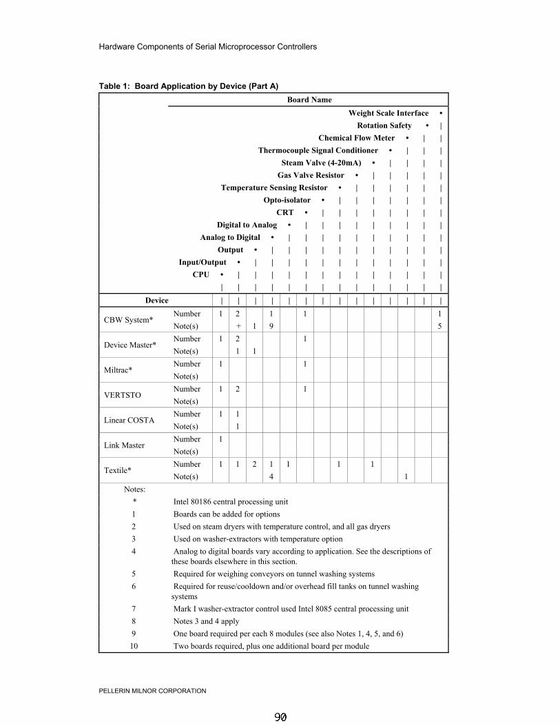
Hardware Components of Serial Microprocessor Controllers
PELLERIN MILNOR CORPORATION
Table 1: Board Application by Device (Part A) Board Name
Weight Scale Interface • Rotation Safety • |
Chemical Flow Meter • | | Thermocouple Signal Conditioner • | | |
Steam Valve (4-20mA) • | | | | Gas Valve Resistor • | | | | |
Temperature Sensing Resistor • | | | | | | Opto-isolator • | | | | | | |
CRT • | | | | | | | | Digital to Analog • | | | | | | | | |
Analog to Digital • | | | | | | | | | | Output • | | | | | | | | | | |
Input/Output • | | | | | | | | | | | | CPU • | | | | | | | | | | | | |
| | | | | | | | | | | | | | Device | | | | | | | | | | | | | |
Number 1 2 1 1 1 CBW System*
Note(s) + 1 9 5 Number 1 2 1
Device Master* Note(s) 1 1 Number 1 1
Miltrac* Note(s) Number 1 2 1
VERTSTO Note(s) Number 1 1
Linear COSTA Note(s) 1 Number 1
Link Master Note(s) Number 1 1 2 1 1 1 1
Textile* Note(s) 4 1
Notes: * Intel 80186 central processing unit1 Boards can be added for options2 Used on steam dryers with temperature control, and all gas dryers3 Used on washer-extractors with temperature option4 Analog to digital boards vary according to application. See the descriptions of
these boards elsewhere in this section.5 Required for weighing conveyors on tunnel washing systems6 Required for reuse/cooldown and/or overhead fill tanks on tunnel washing
systems7 Mark I washer-extractor control used Intel 8085 central processing unit8 Notes 3 and 4 apply9 One board required per each 8 modules (see also Notes 1, 4, 5, and 6)10 Two boards required, plus one additional board per module

PELLERIN MILNOR CORPORATION
Table 2: Board Application by Device (Part B) Board Name
Weight Scale Interface • Rotation Safety • |
Chemical Flow Meter • | | Thermocouple Signal Conditioner • | | |
Steam Valve (4-20mA) • | | | | Gas Valve Resistor • | | | | |
Temperature Sensing Resistor • | | | | | | Opto-isolator • | | | | | | |
CRT • | | | | | | | | Digital to Analog • | | | | | | | | |
Analog to Digital • | | | | | | | | | | Output • | | | | | | | | | | |
Input/Output • | | | | | | | | | | | | CPU • | | | | | | | | | | | | |
| | | | | | | | | | | | | | Device | | | | | | | | | | | | | |
Number 1 2COBUC
Note(s) 1 1 Number 1 2
COSHA Note(s) 1 Number 1 2 1 1 1 1 1 1
Dryer Note(s) 4 2 2 2 Number 1 2 1
Extractor Note(s) 1 1 Number 1 2 1 1
Press Note(s) 1 1 Number 1 1 1 1 1 1
W/E (Mark I) Note(s) 7 1 1 8 1 Number 1 1 1 1 1 1
W/E (Mark II-VI) Note(s) 1 1 8 1 1
Notes: * Intel 80186 central processing unit1 Boards can be added for options2 Used on steam dryers with temperature control, and all gas dryers3 Used on washer-extractors with temperature option4 Analog to digital boards vary according to application. See the descriptions of
these boards elsewhere in this section.5 Required for weighing conveyors on tunnel washing systems6 Required for reuse/cooldown and/or overhead fill tanks on tunnel washing
systems7 Mark I washer-extractor control used Intel 8085 central processing unit8 Notes 3 and 4 apply9 One board required per each 8 modules (see also Notes 1, 4, 5, and 6)10 Two boards required, plus one additional board per module

Hardware Components of Serial Microprocessor Controllers
PELLERIN MILNOR CORPORATION
4. Assigning Board AddressesThe input/output board, output board, analog to digital board, and digital to analog board eachhave two rotary switches which establish the address for each board. This allows each board tocommunicate serially with the microprocessor in its device while sending and receiving its ownmessages. In a battery of machines, the rotary switches are identical for each identical peripheralboard in each identical machine (e.g., the first input/output board (I/O-1) in each washer-extractorhas identical rotary switch settings). When a microprocessor must communicate with a higherlevel control (e.g., when all dryers communicate with the MilData® system), the higher levelcontrol must know the address of each microprocessor. For 8088 microprocessors, the high levelcontrol knows the address of each device because that information was established duringconfiguration (e.g., see Miltrac Address configure decision in the programming manual for anydevice that communicates with Miltrac).

PELLERIN MILNOR CORPORATION
Table 3: Rotary Switch Settings COSHA ¬
COBUC ¬ Device Master ¬
Dryer ¬ Textile ¬
Linear COSTO ¬ One-Stage Press ¬
Two-Stage Press ¬ Extractor ¬
Devices
VERTSTO ¬ Washer-Extractor ¬
Board SW2 2* 2 2 2 2
Analog to Digital SW1 1* 1 1 1 1 SW2 3* 3 3 3
Digital to Analog SW1 1* 1 1 1 SW2 0 0 0 0 0 0 0 0 0
Input/Output #1 SW1 1 1 1 1 1 1 1 1 1 SW2 0* 0 0* 0 0 0* 0* 0 0 0 0
Input/Output #2 SW1 2* 2 2* 2 2 2* 2* 2 2 2 2 SW2 0* 0* 0* 0* 0* 0*
Input/Output #3 SW1 3* 3* 3* 3* 3* 3* SW2 0 0* 0* 0* 0*
Input/Output #4 SW1 4 4* 4* 4* 4* SW2 1 1 1 1 1 1 1*
Output #1 SW1 1 1 1 1 1 1 1* SW2 1* 1* 1* 1 1*
Output #2 SW1 2* 2* 2* 2 2* SW2 1 1* 1*
Output #3 SW1 3 3* 3*
Notes: * Optional boards
1 See schematics for rotary switch positions on tunnel washer systemdevices.
— End of BICMDF01 —

How to Upgrade Microprocessor EPROM Chips
PELLERIN MILNOR CORPORATION
BICMUM01 (Published) Book specs- Dates: 20040817 / 20040817 / 20040817 Lang: ENG01 Applic: CWW
How to Upgrade Microprocessor EPROM ChipsMilnor® microprocessor software is continually upgraded to improve performance and maximizeefficiency. Depending on the software change, the new software EPROM (Erasable,Programmable Read-Only Memory) chips may be offered for sale or for no charge to thecustomer. When a set of these chips is changed in the field, ensure that the software version beinginstalled matches the machine hardware, and that the chips are installed in the proper socketpositions and orientation.
1. How to Change EPROMsWARNING 1 : Electrocution and Electrical Burn Hazards—Contact with high voltagewill electrocute or burn you. Power switches on the machine and the control box do not eliminatethese hazards. High voltage is present at the machine unless the main machine power disconnectis off.• Do not attempt unauthorized servicing, repairs, or modification.• Lock out and tag out power at the main machine disconnect before servicing, or in
accordance with factory service procedures.
1.1. Remove and Replace EPROM Chips1. Make sure all power to the machine is off.2. Locate the chips as described in Section 2 “Location of EPROM Chips”. Note the orientation
of the chips as shown in the figure(s) below.3. Use a chip removal tool or another small flat tool to carefully remove each EPROM chip
from its base. Be sure to note the numerical order of each chip and the orientation to the keynotch on the socket.
4. Install new chips, making sure the key notch on each chip is properly oriented and that allpins enter the proper holes in the socket, as shown in Figure 1. If necessary, slightly bend thepins on the EPROM chip to align the pins with the holes in the socket. After inserting eachchip, verify that all pins are seated in the socket.

How to Upgrade Microprocessor EPROM Chips
PELLERIN MILNOR CORPORATION
Figure 1: EPROM Chip Identification and Installation
EPROM Chip and Socket Legend
.
1. Label2. EPROM chip3. Key notch4. EPROM socket
CAUTION 2 : Machine Damage Hazards—Incorrectly installing any EPROM chip maydestroy or damage the chip or cause the machine or the display to operate erratically.• Match each chip with its corresponding socket. Each EPROM chip will operate in only
one socket, although it may physically fit into others.• Align each chip so every pin mates with the correct hole in the socket.
1.2. Verify Proper EPROM Chip Installation—After installing new EPROM chips, applypower to the machine and turn the machine on. If the chips are properly installed, the display willcontinue with the normal display sequence when powering up. If the display is blank or appearsunusual, turn the machine off at once and verify that the chips are correctly oriented in thesockets.
2. Location of EPROM ChipsDepending on machine model and type, the microprocessor may be an Intel 8085, Intel 8088, orIntel 80186. Each microprocessor board requires at least one EPROM chip for proper operation,but these chips may be located differently on each type of processor board. The followinginformation describes the location and arrangement of the EPROM chips on each type of board,as well as the favored location for checking the voltages required by each type of board.
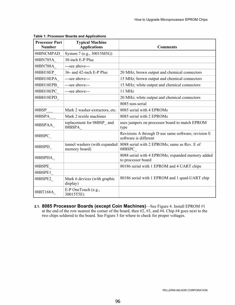
How to Upgrade Microprocessor EPROM Chips
PELLERIN MILNOR CORPORATION
Table 1: Processor Boards and Applications
Processor PartNumber
Typical MachineApplications Comments
08BNCMPAD_ System 7 (e.g., 30015M5G)08BN785A_ 30-inch E-P Plus08BN788A_ ---see above---08BH18EP_ 36- and 42-inch E-P Plus 20 MHz; brown output and chemical connectors08BH18EPA_ ---see above--- 15 MHz; brown output and chemical connectors08BH18EPB_ ---see above--- 15 MHz; white output and chemical connectors08BH18EPC_ ---see above--- 11 MHz08BH18EPD_ 20 MHz; white output and chemical connectors
8085 non-serial08BSP___ Mark 2 washer-extractors, etc. 8085 serial with 4 EPROMs08BSPA___ Mark 2 textile machines 8085 serial with 2 EPROMs
08BSPAA_ replacement for 08BSP_ and08BSPA_
uses jumpers on processor board to match EPROMtype
08BSPC_ Revisions A through D use same software; revision Esoftware is different
08BSPD_ tunnel washers (with expandedmemory board)
8088 serial with 2 EPROMs; same as Rev. E of08BSPC_
08BSPDA_ 8088 serial with 4 EPROMs; expanded memory addedto processor board
08BSPE_ 80186 serial with 1 EPROM and 4 UART chips08BSPE1_08BSPE2_ Mark 6 devices (with graphic
display)80186 serial with 1 EPROM and 1 quad-UART chip
08BT168A_ E-P OneTouch (e.g.,30015T5E)
2.1. 8085 Processor Boards (except Coin Machines)—See Figure 4. Install EPROM #1at the end of the row nearest the corner of the board, then #2, #3, and #4. Chip #4 goes next to thetwo chips soldered to the board. See Figure 3 for where to check for proper voltages.

How to Upgrade Microprocessor EPROM Chips
PELLERIN MILNOR CORPORATION
Figure 2: Replacement Processor Board
08BSPAA_ Legend
.
A. Jumpers for settingEPROM capacity
B. EPROM socket 1C. EPROM socket 2D. EPROM socket 3E. EPROM socket 4F. DIP switchG. CapacitorH. Microprocessor
Figure 3: Where to Check Processor Board Voltages
Typical MTA-31 Legend
.
1. Ground (Earth)2. Negative 12VDC3. Positive 12VDC4. Positive 5VDC

How to Upgrade Microprocessor EPROM Chips
PELLERIN MILNOR CORPORATION
Figure 4: 8085 Processor Boards (Except Coin Machine)
Typical 08BSP_ and 08BSPx_ Processor Boards Legend
.
A. 8085 microprocessor chipB. EPROMsC. Soldered chipsD. DIP switchE. BatteryF. 08BSPB_ processor board
2.2. 8088 Processor Boards without Memory Expansion Board—See Table 2“EPROM Locations for 8088 Processor Applications” and Figure 6. If the set consists of onlyone EPROM, install it in socket A of Figure 6 . If two EPROMs comprise the set, install EPROM#2 in socket A and EPROM #1 in socket B. Always install the highest numbered EPROM insocket A. If the set consists of more than two EPROMs, a memory expansion board must bepresent in the machine along with the processor board.
Figure 5: Typical 8088 Processor Board without Memory Expansion Board
08BSPC_ Processor Board Legend
.
A. EPROMsB. 8088 processor chipC. MTA31 for voltage
verification
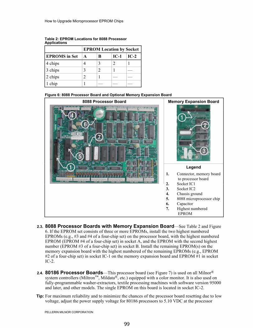
How to Upgrade Microprocessor EPROM Chips
PELLERIN MILNOR CORPORATION
Table 2: EPROM Locations for 8088 ProcessorApplications
EPROM Location by SocketEPROMS in Set A B IC-1 IC-24 chips 4 3 2 13 chips 3 2 1 —2 chips 2 1 — —1 chip 1 — — —
Figure 6: 8088 Processor Board and Optional Memory Expansion Board
8088 Processor Board Memory Expansion Board
Legend
.
1. Connector, memory boardto processor board
2. Socket IC13. Socket IC24. Chassis ground5. 8088 microprocessor chip6. Capacitor7. Highest numbered
EPROM
2.3. 8088 Processor Boards with Memory Expansion Board—See Table 2 and Figure6. If the EPROM set consists of three or more EPROMs, install the two highest numberedEPROMs (e.g., #3 and #4 of a four-chip set) on the processor board, with the highest numberedEPROM (EPROM #4 of a four-chip set) in socket A, and the EPROM with the second highestnumber (EPROM #3 of a four-chip set) in socket B. Install the remaining EPROM(s) on thememory expansion board with the highest numbered of the remaining EPROMs (e.g., EPROM#2 of a four-chip set) in socket IC-1 on the memory expansion board and EPROM #1 in socketIC-2.
2.4. 80186 Processor Boards—This processor board (see Figure 7) is used on all Milnor®
system controllers (Miltron™, Mildata®, etc.) equipped with a color monitor. It is also used onfully-programmable washer-extractors, textile processing machines with software version 95000and later, and other models. The single EPROM on this board is located in socket IC-2.
Tip: For maximum reliability and to minimize the chances of the processor board resetting due to lowvoltage, adjust the power supply voltage for 80186 processors to 5.10 VDC at the processor

How to Upgrade Microprocessor EPROM Chips
PELLERIN MILNOR CORPORATION
board.
There are three major revisions of this board, both of which have Milnor part numbers startingwith “08BSPE”. If the seventh character is a number “1,” the board is a later version with a singlefour-channel communications chip. If the seventh character of the part number is a letter, theboard is an earlier version with four one-channel communications chips.
The third version of 80186 processor board—with part number “08BSPE2_”—can be configuredvia a jumper on the board to operate either a vacuum fluorescent text display, or a flat panel colorgraphic LCD display. The jumper controls the serial communications port on MTA30.
Supplement 1
Rules for Replacing 80186 Processor Boards
Processor board “08BSPET” is obsolete. Depending on machine model and build date, thisboard can be replaced by either “08BSPE1T” or “08BSPE2T”, but new software is required.Contact Milnor's service engineering department to determine the appropriate replacementboard and software.
Processor board “08BSPE1T” has been superseded by board “08BSPE2T”(see Figure 9). Ifyour machine uses a two-line or four-line vacuum fluorescent text display, either “...E1T” or“...E2T” will work with your existing software. The most important difference between thesetwo boards is jumper J1 on the “...E2T” board for selecting the flat panel color graphic LCDdisplay. This jumper must be set to the TXT or NO position for machines with a vacuumfluorescent display, or in the GPX (graphics) position for machines with a color LCD display.
Figure 7: Obsolete 80186 Processor Board
08BSPE_ Processor Board Legend
.
1. Chassis ground2. Capacitor3. 80186 microprocessor
chip4. EPROM in socket IC-25. ROM socket (empty
except in Japan)

How to Upgrade Microprocessor EPROM Chips
PELLERIN MILNOR CORPORATION
Figure 8: 80186 Processor Board
08BSPE1_ Processor Board Legend
.
A. Chassis groundB. CapacitorC. Quad-UART chipD. 80186 microprocessorE. EPROMF. Rotary DIP switches for
keypadG. ROM socket (empty
except in Japan)
Figure 9: 08BSPE2_ 80186 Processor Board
Detail Legend
.
A. Jumper for selectingdisplay type
— End of BICMUM01 —
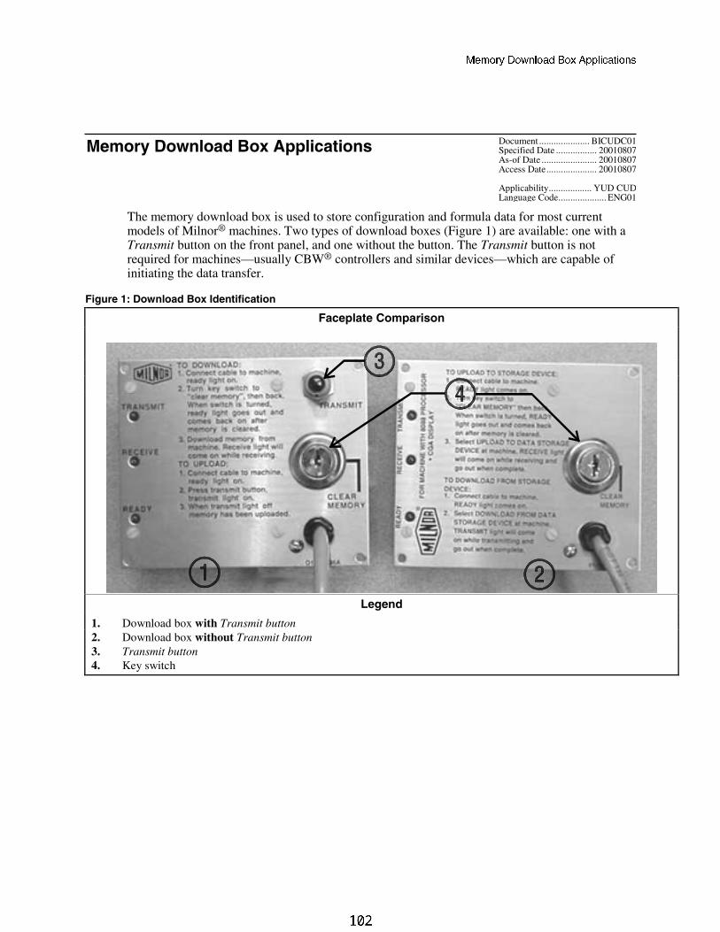
=U]_bi 4_g^\_QT 2_h 1``\YSQdY_^c
Document ..................... BICUDC01Specified Date ................. 20010807As-of Date ....................... 20010807Access Date..................... 20010807
Applicability.................. YUD CUD
����� �������� ��� ������������
Language Code.................... ENG01
The memory download box is used to store configuration and formula data for most currentmodels of Milnor® machines. Two types of download boxes (Figure 1) are available: one with aTransmit button on the front panel, and one without the button. The Transmit button is notrequired for machines—usually CBW® controllers and similar devices—which are capable ofinitiating the data transfer.
Figure 1: Download Box Identification
Faceplate Comparison
Legend
1. Download box with Transmit button2. Download box without Transmit button3. Transmit button4. Key switch

=U]_bi 4_g^\_QT 2_h 1``\YSQdY_^c
Figure 2: Rear View of Circuit Board
View Legend
1. DIP switch2. Software chip3. Location of Transmit
button, if equipped4. Key switch
Bd__[T\T]c
8]cTa_aTcX]V cWT 38? BfXcRW BTccX]Vb
Use the following codes and their definitions to set the DIP switch positions for the equipment,as shown in Table 1.
A. All switch positions are OFF.
B. Switch position 4 is ON; all other switch positions are OFF.
C. Switch position 5 is ON; all other switch positions are OFF.
D. Switch positions 1 and 5 are ON; all other switch positions are OFF.
=^cT ) If necessary, a memory download box with the Transmit button may be used to storeconfiguration and formula data from any machine that's capable of downloading. When using a button-equipped download box to store data from one of the devices listed in Table 1 as requiring the Transmitbutton, ignore the button. The download will begin when commanded from the device control panel.

=U]_bi 4_g^\_QT 2_h 1``\YSQdY_^c
Table 1: DIP Switch Positions
ProcessorBoard Software Version
DIP SwitchSetting
ProcessorBoard Software Version
DIP SwitchSetting
Uses Memory Download Box WITH TransmitButton
Uses Memory Download Box WITHOUTTransmit Button
Washer-extractor Models Miltron Controller for CBW System
8088 All C 8088 All A
98000-98003 C 80186 All B
98004-99004 not supported Miltrac
99005-9900B D 8088 All A80186
20000-20003 D 80186 All B
FxW, FxP, and FxS Washer-extractor models Milrail Rail Controller
8088 All C 8088 All A
98000-98003 C 80186 All B
98004-98009 not supported Device Master
9800A-9800H D 8085 All not supported80186
20000-2000B D 8088 All not supported
Textile and Dye Machine Models 94000-94017 not supported
8088 All C 94018 B
95000-95305M C
80186
20000-present B
95305N-95306 D Linear Costo Master80186
20000-20004 D 8085 All not supported
Dryer Models 8088 All not supported
8088 All C 94000-94011 not supported
80186 All C80186
20000-present B
Centrifugal Extractor Models Key:
8088 All C A All switch positions OFF
80186 All C B Position 4 ON; all others OFF
Single-station Press Models C Position 5 ON; all others OFF
8088 All C D Positions 1 and 5 ON; all others OFF
— End of BICUDC01 —
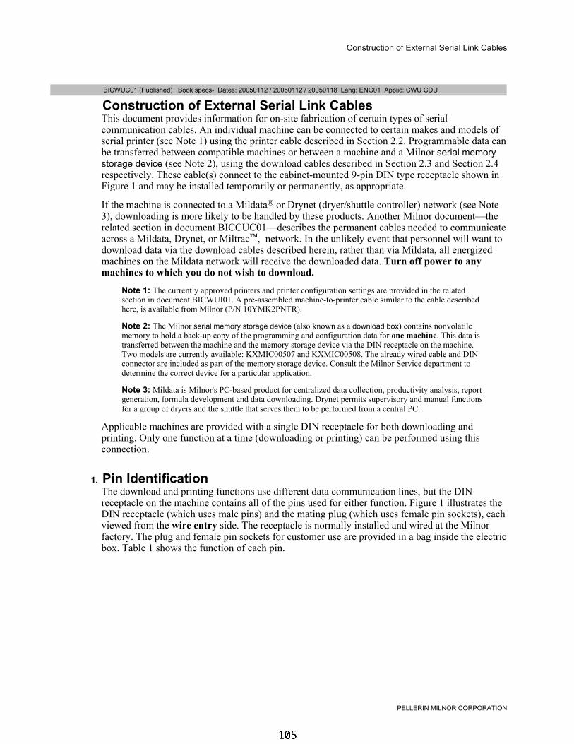
Construction of External Serial Link Cables
PELLERIN MILNOR CORPORATION
BICWUC01 (Published) Book specs- Dates: 20050112 / 20050112 / 20050118 Lang: ENG01 Applic: CWU CDU
Construction of External Serial Link CablesThis document provides information for on-site fabrication of certain types of serialcommunication cables. An individual machine can be connected to certain makes and models ofserial printer (see Note 1) using the printer cable described in Section 2.2. Programmable data canbe transferred between compatible machines or between a machine and a Milnor serial memorystorage device (see Note 2), using the download cables described in Section 2.3 and Section 2.4respectively. These cable(s) connect to the cabinet-mounted 9-pin DIN type receptacle shown inFigure 1 and may be installed temporarily or permanently, as appropriate.
If the machine is connected to a Mildata® or Drynet (dryer/shuttle controller) network (see Note3), downloading is more likely to be handled by these products. Another Milnor document—therelated section in document BICCUC01—describes the permanent cables needed to communicateacross a Mildata, Drynet, or Miltrac™, network. In the unlikely event that personnel will want todownload data via the download cables described herein, rather than via Mildata, all energizedmachines on the Mildata network will receive the downloaded data. Turn off power to anymachines to which you do not wish to download.
Note 1: The currently approved printers and printer configuration settings are provided in the relatedsection in document BICWUI01. A pre-assembled machine-to-printer cable similar to the cable describedhere, is available from Milnor (P/N 10YMK2PNTR).
Note 2: The Milnor serial memory storage device (also known as a download box) contains nonvolatilememory to hold a back-up copy of the programming and configuration data for one machine. This data istransferred between the machine and the memory storage device via the DIN receptacle on the machine.Two models are currently available: KXMIC00507 and KXMIC00508. The already wired cable and DINconnector are included as part of the memory storage device. Consult the Milnor Service department todetermine the correct device for a particular application.
Note 3: Mildata is Milnor's PC-based product for centralized data collection, productivity analysis, reportgeneration, formula development and data downloading. Drynet permits supervisory and manual functionsfor a group of dryers and the shuttle that serves them to be performed from a central PC.
Applicable machines are provided with a single DIN receptacle for both downloading andprinting. Only one function at a time (downloading or printing) can be performed using thisconnection.
1. Pin IdentificationThe download and printing functions use different data communication lines, but the DINreceptacle on the machine contains all of the pins used for either function. Figure 1 illustrates theDIN receptacle (which uses male pins) and the mating plug (which uses female pin sockets), eachviewed from the wire entry side. The receptacle is normally installed and wired at the Milnorfactory. The plug and female pin sockets for customer use are provided in a bag inside the electricbox. Table 1 shows the function of each pin.
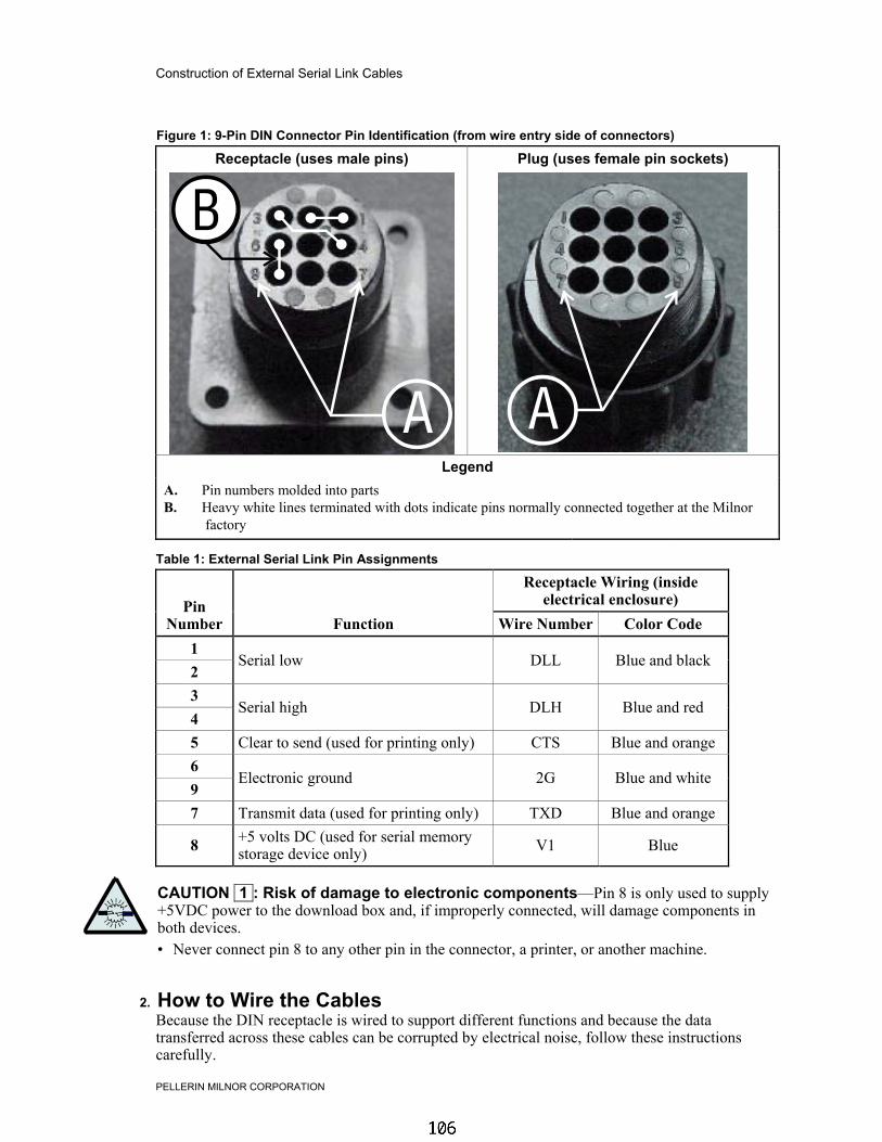
Construction of External Serial Link Cables
PELLERIN MILNOR CORPORATION
Figure 1: 9-Pin DIN Connector Pin Identification (from wire entry side of connectors)
Receptacle (uses male pins) Plug (uses female pin sockets)
LegendA. Pin numbers molded into partsB. Heavy white lines terminated with dots indicate pins normally connected together at the Milnor
factory.
Table 1: External Serial Link Pin Assignments
Receptacle Wiring (insideelectrical enclosure)Pin
Number Function Wire Number Color Code12
Serial low DLL Blue and black
34
Serial high DLH Blue and red
5 Clear to send (used for printing only) CTS Blue and orange69
Electronic ground 2G Blue and white
7 Transmit data (used for printing only) TXD Blue and orange
8 +5 volts DC (used for serial memorystorage device only) V1 Blue
CAUTION 1 : Risk of damage to electronic components—Pin 8 is only used to supply+5VDC power to the download box and, if improperly connected, will damage components inboth devices.• Never connect pin 8 to any other pin in the connector, a printer, or another machine.
2. How to Wire the CablesBecause the DIN receptacle is wired to support different functions and because the datatransferred across these cables can be corrupted by electrical noise, follow these instructionscarefully.
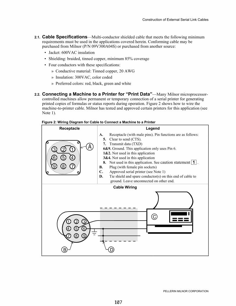
Construction of External Serial Link Cables
PELLERIN MILNOR CORPORATION
2.1. Cable Specifications—Multi-conductor shielded cable that meets the following minimumrequirements must be used in the applications covered herein. Conforming cable may bepurchased from Milnor (P/N 09V300A04S) or purchased from another source:
• Jacket: 600VAC insulation• Shielding: braided, tinned copper, minimum 85% coverage• Four conductors with these specifications:
» Conductive material: Tinned copper, 20 AWG» Insulation: 300VAC, color coded» Preferred colors: red, black, green and white
2.2. Connecting a Machine to a Printer for “Print Data”—Many Milnor microprocessor-controlled machines allow permanent or temporary connection of a serial printer for generatingprinted copies of formulas or status reports during operation. Figure 2 shows how to wire themachine-to-printer cable. Milnor has tested and approved certain printers for this application (seeNote 1).
Figure 2: Wiring Diagram for Cable to Connect a Machine to a Printer
Receptacle LegendA. Receptacle (with male pins). Pin functions are as follows: 5. Clear to send (CTS). 7. Transmit data (TXD) 6&9. Ground. This application only uses Pin 6. 1&2. Not used in this application 3&4. Not used in this application 8. Not used in this application. See caution statement 1 .B. Plug (with female pin sockets)C. Approved serial printer (see Note 1)D. Tie shield and spare conductor(s) on this end of cable to
ground. Leave unconnected on other end.Cable Wiring
.

Construction of External Serial Link Cables
PELLERIN MILNOR CORPORATION
2.3. Connecting Two or More Machines for Machine-to-machine Transfer—Figure3 shows how to wire a cable to connect a bank of identical machines (the Figure 3 exampleshows connections for four machines) so that data programmed on one machine in the group canbe downloaded to all other machines simultaneously. This cable is referred to as a daisy chainbecause it runs in segments from machine to machine, connecting all machines in the group.
Figure 3: Wiring Diagram for Cable to Connect Two or More Machines
Receptacle On Each Machine LegendA. Receptacle on machine (with male pins). Pin functions are as
follows: 1&2. Serial low 3&4. Serial high 6&9. Ground 5&7. Not used in this application 8. Not used in this application. See caution statement 1 .B. Plug on cable (with female pin sockets)C. Connect together each segment of shield so that it has
continuity across entire daisy chain.D. Connect together each segment of an unused conductor so that
it has continuity across entire daisy chain.E. Tie shield and spare conductor(s) on one end of daisy chain to
ground. Leave unconnected on other end of daisy chain.Cable Wiring
.
The internal connections on each receptacle (machine) between pins 1 and 2, 3 and 4, and 6 and 9make it easier to wire the cable because it is not necessary to jumper these pins together on thecable. However, this also means that every plug on the daisy chain must be plugged into areceptacle. Otherwise, the serial low, serial high, and ground conductors will not have continuityacross the entire daisy chain and some machines will not receive data.
Rules and details about downloading among machines are fully described in the programmingsection of the reference manual.
2.4. Connecting a Machine to a Serial Memory Storage Device—The cable used withthe serial memory storage device (download box) available from Milnor, see Note 2, ispermanently attached to the storage device. Cable fabrication, as shown in Figure 4, is notrequired except for replacing a damaged cable. The memory storage device is the onlyapplication in which the power conductor (Pin 8) is used.

Construction of External Serial Link Cables
PELLERIN MILNOR CORPORATION
Figure 4: Wiring Diagram for Cable to Connect a Machine to a Serial Memory Storage Device
Receptacle LegendA. Receptacle on machine (with male pins). Pin functions are as follows: 1&2. Serial low. This application only uses Pin 1. 3&4. Serial high. This application only uses Pin 3. 6&9. Ground. This application only uses Pin 9. 5&7. Not used in this application. 8. +5VDC. Provides power to memory storage device.B. Plug on cable (with female pin sockets)C. Memory storage device (front panel may be different)D. Tie shield on this end of cable to ground. Leave unconnected on other end.
Plug and Storage Device
.
— End of BICWUC01 —
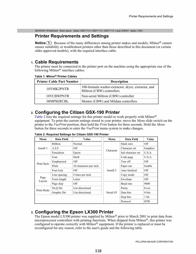
Printer Requirements and Settings
PELLERIN MILNOR CORPORATION
BICWUI01 (Published) Book specs- Dates: 20071113 / 20071113 / 20071113 Lang: ENG01 Applic: CDU
Printer Requirements and SettingsNotice 1 : Because of the many differences among printer makes and models, Milnor® cannotensure suitability or troubleshoot printers other than those described in this document (or certainolder approved models), with the required interface cable.
1. Cable RequirementsThe printer must be connected to the printer port on the machine using the appropriate one of thefollowing Milnor® interface cables:
Table 1: Milnor® Printer Cables
Printer Cable Part Number Description
10YMK2PNTR 100-formula washer-extractor, dryer, extractor, andMiltron (CBW) controllers
10YCBWPNTR Non-serial Miltron (CBW) controller08MPSERCBL Mentor (CBW) and Mildata controllers
2. Configuring the Citizen GSX-190 PrinterTable 2 lists the required settings for this printer model to work properly with Milnor®
equipment. To print the current settings stored in your printer, move the Menu slide switch on theprinter to the VuePrint position, then hold the Print button for three seconds. Hold the Menubutton for three seconds to enter the VuePrint menu system to make changes.
Table 2: Required Settings for Citizen GSX-190 PrinterMenu Data Field Value Menu Data Field Value
Ribbon Normal Slash zero OffA.S.F. Off Character set GraphicsInstall 1Emulation Epson Intl character set U.S.A.Font Draft
Character
Code page U.S.A.Emphasized Off Tear off OffPitch 10 characters per inch Paper out Enable
Print Style
Font lock Off Auto linefeed OffLine spacing 6 lines per inch Copy mode OffForm length Letter
Install 2
Envelope OffPageLayout
Page skip Off Baud rate 9600NLQ Dir Uni-directional Parity Even
Print ModeGraphic Dir Uni-directional Data bits 8 bits
Stop bits 1 bitSerial I/F
Protocol DTR
3. Configuring the Epson LX300 PrinterThe Epson model LX300 printer was supplied by Milnor® prior to March 2001 to print data frommicroprocessor controllers with printing functions. When shipped from Milnor®, this printer wasconfigured to operate correctly with Milnor® equipment. If the printer is replaced or must bereconfigured for any reason, refer to the user's guide and the following table.

Printer Requirements and Settings
PELLERIN MILNOR CORPORATION
Table 3: Required Settings for Epson LX300 Printer
Data Field Value Data Field Value
Character spacing 10 characters perinch Tractor Single
Shape of zero 0 Interface SerialSkip over perforation Off Bit rate 9600 bpsCharacter table PC 437 Parity EvenAuto line feed Off Data length 8 bitsPage length 11 inches ETX/ACT OnAuto tear off Off
4. Previous Printer ModelsThe Epson LX300 printer replaced the Epson LX-810, which replaced the Epson LX-800. Forinformation on these older printer models, request document MSSM0251AE from the Milnorfactory.
— End of BICWUI01 —

MSSM0248AE/9526BV (1 of 1)
ÈHOW “CHEMWAIT” WORKS INMILNOR MARK I, II, III, IV, AND V MICROPROCESSORWASHER-EXTRACTOR CONTROLLERS
“CHEMWAIT” is a feature in the Milnor washer-extractor controller whereby a central chemical injectionsystem can service several washer-extractors. When the chemical injection system is serving another machine, eachwasher-extractor controller can accept a command from the injection system to “stop the timer and do not start theinjection signal.”
An independent output from Milnor to the chemical system declares: “THIS MACHINE DESIRES TOINJECT ONE OR MORE UNNAMED CHEMICAL(S).” (The same independent output is used regardless ofthe chemical(s) that will be subsequently requested.) To cause the Milnor timer to stop and delay the “COM-MENCE CHEMICAL INJECTION” signals, an independent input from the chemical system to Milnor mustrespond, “WAIT” (within two seconds).
In the absence of a “WAIT” response, the Milnor signal(s) start two seconds after the inject request, or twoseconds after the “WAIT” response is extinguished. The duration of the inject signals will be whatever is com-manded in the washing program.
“WAIT” commands will be ignored unless the machine has desired to inject less than two seconds before.
When several washer-extractors desire chemicals simultaneously, it is the central chemical injection systems’ re-sponsibility to decide which machine will receive chemicals first. It is also the central chemical injection systems’ respon-sibility to cope with the situation when one or more washer-extractors simultaneously desire more than one chemical,although the latter case may be avoided by only commanding one chemical injection at a time—using Milnor’s exclusive“do not drain” feature to subsequently inject more than one chemical in the same bath.
The “DESIRES TO INJECT” and “WAIT” signals must be via potential-free contacts capable of faithfullyhandling 10 MA (.01 amperes) at 5 VDC. The specific “COMMENCE CHEMICAL INJECTON” signals willbe either 120 VAC or 240 VAC, depending on the specific MILNOR model, and via relay contacts capable ofconducting a maximum of 9 VA (i.e., a maximum of either 80 MA (.08 amperes) at 120 VAC or 40 MA (.04amperes) at 240 VAC).
“CHEMWAIT” is presently available in all Mark I, II, III, IV, and V controllers, but does require the optional#2 output board. Ask factory for more information.
B
B

MSSM0238BE/9527BV (1 of 6)
ÈADJUSTING LEVEL SENSING APPARATUSES AND SETTING LEVELS ON 100-FORMULA WASHER-EXTRACTORS AND TEXTILE MACHINES
ÊHow Level Control WorksËTypes of Level Sensing Apparatuses —Three types of apparatuses are used on these machines: floatchamber assemblies, pressure switches, and pressure transducers.
A float chamber assembly (FIGURE 1) is an open-top, metal tube connected to the shell below the water line.The height of water in the tube is the same as in the cylinder. Changes in the level cause a float, rod, and actuatingarm to move, which in turn, actuate either of two switches. Each switch actuates at one pre-set level.
A pressure switch (FIGURE 2) actuates when the air inside an airtight chamber connected to the washer shellbelow the water line reaches a certain pressure. As the liquor level changes, the air pressure in the chamber changes.Each pressure switch actuates at one pre-set level.
A pressure transducer (electronic level control) works similar to a pressure switch, except that it produces avoltage which varies with changes in pressure. The varying voltage is converted into digital data which the micro-processor controller can interpret and display as inches or centimeters of water.
ËWhich Apparatuses and Methods of Level Control Are Used —Table A, below, shows whichapparatuses are used on various machine types. These apparatuses permit controlling the liquor level using themethods listed in the table, unless the machine is equipped and configured for metered water (specifying a quantityof water). In the latter case, the level sensing apparatuses are not used to control levels, but they are used by themicroprocessor controller for certain internal lockouts (e.g., permit steaming only after low level is achieved).
ÏTable A: Apparatuses and Methods for Each Machine Type
Machine Type Level Level Sensing ApparatusHow level is specified in washformula (no metered water)
Divided cylin-der models
Level 3=high (rinse) pressure switch SPLL3 Select one of the four pre-setlevelsLevel 2=low (wash) pressure switch SPLL1
Level 1=below low (starch) pressure switch SPLLLLevel 0=no water (shake out) N. A.
36021xxx and36026xxx openpocket models
Level 3=high (rinse) float chamber/switch SLLL3 Select one of the four pre-setlevelsLevel 2=low (wash) float chamber/switch SLLLL
Level 1=below low (starch) pressure switch SPLL1Level 0=no water (shake out) N. A.OK to open door pressure switch SPLLS N. A.
42026xxx andlarger openpocket models
Processing levelspressure transducer
Specify inches or centimeterswithin a pre-set range
OK to open door N. A.Fill while tilted N. A.
NOTE: There is no separate cooldown level. Cooldown occurs at the commanded level in the bath in whichcooldown is commenced.
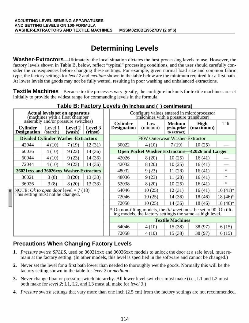
ÊDetermining LevelsËWasher-Extractors —Ultimately, the local situation dictates the best processing levels to use. However, thefactory levels shown in Table B, below, reflect “typical” processing conditions, and the user should carefully con-sider the consequences before changing these settings. For example, given normal load size and common fabrictype, the factory settings for level 2 and medium shown in the table below are the minimum required for a first bath.At lower levels the goods may not be fully wetted, resulting in poor washing and unbalanced extractions.
ËTextile Machines —Because textile processes vary greatly, the configure lockouts for textile machines are setinitially to provide the widest range for commanding levels in the formula.
ÏTable B: Factory Levels (in inches and ( ) centimeters)Actual levels set on apparatus(machines with a float chamber
assembly and/or pressure switches)
Configure values entered in microprocessor(machines with a pressure transducer)
CylinderDesignation
Low(minium)
Medium(min. priorto extract)
High(maximum)
TiltCylinder
DesignationLevel 1(starch)
Level 2(wash)
Level 3(rinse)
Divided Cylinder Washer-Extractors F8W Outerwear Washer-Extractor 42044 4 (10) 7 (19) 12 (31) 30022 4 (10) 7 (19) 10 (25) —60036 4 (10) 9 (23) 14 (36) Open Pocket Washer Extractors—42026 and Larger60044 4 (10) 9 (23) 14 (36) 42026 8 (20) 10 (25) 16 (41) —72044 4 (10) 9 (23) 14 (36) 42032 8 (20) 10 (25) 16 (41) —
36021xxx and 36026xxx Washer-Extractors 48032 9 (23) 11 (28) 16 (41) *36021 3 (8) 8 (20) 13 (33) 48036 9 (23) 11 (28) 16 (41) *36026 3 (8) 8 (20) 13 (33) 52038 8 (20) 10 (25) 16 (41) *
NOTE: Ok to open door level = 7 (18)This setting must not be changed.
64046 10 (25) 12 (31) 16 (41) 16 (41)*72046 10 (25) 14 (36) 18 (46) 18 (46)*72058 10 (25) 14 (36) 18 (46) 18 (46)*
* On non-tilting models, the tilt level must be set to 00. On tilt-ing models, the factory settingis the same as high level.
Textile Machines64046 4 (10) 15 (38) 38 (97) 6 (15)72058 4 (10) 15 (38) 38 (97) 6 (15)
ËPrecautions When Changing Factory Levels1. Pressure switch SPLLS, used on 36021xxx and 36026xxx models to unlock the door at a safe level, must re-
main at the factory setting. (In other models, this level is specified in the software and cannot be changed.)
2. Never set the level for a first bath lower than needed to thoroughly wet the goods. Normally this will be thefactory setting shown in the table for level 2 or medium .
3. Never change float or pressure switch hierarchy. All lower level switches must make (i.e., L1 and L2 mustboth make for level 2; L1, L2, and L3 must all make for level 3.)
4. Pressure switch settings that vary more than one inch (2.5 cm) from the factory settings are not recommended.
B
ADJUSTING LEVEL SENSING APPARATUSES AND SETTING LEVELS ON 100-FORMULA WASHER-EXTRACTORS AND TEXTILE MACHINES MSSM0238BE/9527BV (2 of 6)

ÊAbout Level Adjustments
INJURY AND MACHINE DAMAGE HAZARDS—A knowledge of machine programming, operating,and mechanical/electrical servicing is needed when making level adjustments. These adjustmentsmust be performed only by qualified personnel, in strict compliance with published safety precau-tions.
ËWhen Adjustments Are Needed —If the mounted position of a float chamber assembly or part of itchanges (which can occur when components are replaced), the switches will no longer actuate at the same levels.Similarly, a pressure switch may not actuate at the original level setting as a result of prolonged wear or replacement.In these situations, the pre-set levels must be re-established.
On machines with pressure transducers, the microprocessor may not properly interpret the transducer outputas a result of prolonged wear or replacement of the transducer. In this situation, the transducer must be re-calibrated.
ËApparatuses Used To Make Level Adjustments —Level float-controlled levels are adjusted bymoving the clips on the float rod. Pressure switch-controlled levels are adjusted with the trip point adjusting screwon the switch. On machines with pressure transducers, actual processing levels are not pre-set (levels are specifiedin the formula), but ranges and tilt level are pre-set with the low, medium, high, and tilt level configure decisions.The transducer is calibrated with the tap offset counts configure decision.
ËMeasuring Levels Accurately —The adjustment procedures require filling the machine to a level mark ofknown height. The amount of water needed to achieve a level will vary unpredictably if goods (which both absorbwater and occupy space) are present or if the cylinder is rotating. Always set levels/calibrate with the cylinder atrest and without goods.
On divided cylinder machines (which hang level, front to back), use the graduated sight glass on the shell frontto measure levels. The graduations are in inches or centimeters, depending on the machine’s destination country.
The levels in open pocket cylinders (which slope down to the rear) are measured at the rear (deepest part) ofthe cylinder. Temporary marks must be placed on the cylinder rear wall, as explained below.
ËMarking Levels on an Open Pocket Machine
CONFINED SPACE HAZARDS—Confinement in the cylinder can kill or injure you. Haz-ards include, but are not limited to panic, burns, poisioning, suffocation, heat prostra-tion, biological contamination, and crushing.
☞ Do not enter the cylinder until it has been thoroughly purged, flushed, drained,cooled, and immobilized.
1. Prepare the machine for safe entry and in accordance with all applicable codes (e.g., OSHA permit-requiredconfined space entry requirements). Lock power off at the external disconnect switch.
2. On the inside of the cylinder, measure from the bottom rear and place clearly visible marks on the rear wall. Ifthe machine has a level float and/or pressure switches, mark a line at each level to be set. If the machine hasa pressure transducer, mark a line at high level. The cylinder will be stationary while filling, so the markswill not move.
3. When all personnel are clear, restore machine power.
ADJUSTING LEVEL SENSING APPARATUSES AND SETTING LEVELS ON 100-FORMULA WASHER-EXTRACTORS AND TEXTILE MACHINES MSSM0238BE/9527BV (3 of 6)

ÊLevel Setting Procedures(Machines With a Float Chamber Assembly and/or Pressure Switc hes)
ËGeneral Procedure —Perform the following for each level to be set:
1. Close the door and run Formula 99. (The cylinder will be stationary and without water.)
2. Use the procedures described in “MODIFYING FORMULAS IN PROGRESS,” “Method B . . .” (see Tableof Contents) to fill with cold water just to the mark for the level to be set.
3. Adjust the appropriate apparatus (float chamber assembly or pressure switch) as explained below, just enoughto actuate (as indicated by the proper level number appearing on the display).
ËAccessing and Adjusting the Float Chamber Assembly
ENTANGLE AND SEVER HAZARDS—Contact with moving components normally iso-lated by guards, covers, and panels can entangle you and crush your limbs. Thesecomponents move automatically.
☞ Do not service machine unless qualified and authorized.
The machine must remain pow-ered on while adjusting the float rodclips. Use extreme caution not toreach into the path of any appara-tuses which could move, such as pul-leys or belts. On rigid models, the floatchamber assembly (FIGURE 1) is lo-cated behind the shell. The float rodclips are accessible from the top of themachine. On suspended models, thelevel float is located within the frame.Remove the appropriate panel(s) for ac-cess.
Move clips as shown in FIGURE1. Note that top and bottom clips mustnot be placed closer together than oneinch (25 mm), otherwise the float rodcan bind in the actuator arm.
ËAccessing, Identifying, and Adjusting Pressure Switches
ELECTROCUTION AND ELECTRICAL BURN HAZARDS— Contact with high voltage willelectrocute or burn you. Power switches on the machine and the control box do noteliminate these hazards. High voltage is present at the machine unless the main ma-chine power disconnect is off.
☞ Do not service machine unless qualified and authorized.
ÎFIGURE 1 (MSSM0238BE)
ÎFloat Chamber Assembly—Clip Adjustment
ADJUSTING LEVEL SENSING APPARATUSES AND SETTING LEVELS ON 100-FORMULA WASHER-EXTRACTORS AND TEXTILE MACHINES MSSM0238BE/9527BV (4 of 6)

The machine must remain powered on when adjust-ing pressure switches. Use extreme caution not to touchany electrical conductors on the switch or in the elec-tric box. The trip point adjusting screw may becomeelectrically energized when power is on. Use only aninsulated screwdriver to make adjustments.
Pressure switches (FIGURE 2) are located in the lowvoltage control box. A sticker on the switch and/or a tag inthe control box identify the switches by the functionalnames given in Table A (e.g., SPLL3).
The switch manufacturer calibrates these switches toactuate at a set pressure. When proper levels are verified atthe Milnor factory, the trip point adjusting screw i spainted with wax to hold its adjustment. With an insulated screwdriver, turn the trip point adjusting screw slowly.Turning clockwise causes the switch to actuate at a higher level; turning counter-clockwise actuates it at a lower level.
NOTE: A crimp, cut, or loose connection in the plastic air tube will prevent the pressure switch from func-tioning, causing the machine to overflow. Inspect air tubes periodically.
ÊRange Setting, Calibrating, and Testing Procedures(Machines With a Pressure Transducer )
ËDisabling Metered Water if the Machine Also Has a Flow Meter —If the machine has a flowmeter and is configured for metered water (configure decision N), then the pressure transducer is only used forinternal lockouts. Never-the-less, the transducer must be properly calibrated. The procedures described herein forrange setting and calibrating may be used in this instance provided metered water is disabled, as follows:
1. Write down (or print out) all configure decisions. This is necessary because the next step will cause certainconfigure values to be lost. These must be re-entered later.
2. Set configure decision N (metered water)=0. Now a calibration formula can be programmed, specifying levelsin inches (or centimeters) of water, as explained elsewhere herein.
DATA LOSS AND MALFUNCTION HAZARDS—Existing formulas contain water quantitydata which only applies to metered water. While metered water is disabled:
☞ Do not access existing formulas. The microprocessor will delete the water data.
☞ Do not run existing formulas. The water data will cause the machine to malfunction.
ËSetting the Level Ranges and Tilt Level —The low, medium, and high level configure decisions deter-mine the ranges within which levels may be specified in the wash formula. See “PROGRAMMING . . . ,” “5=CON-FIGURE . . .” for how these values affect the ranges. Set these values as desired. The tilt level configure decisionspecifies the level a tilting machine will fill to while tilted. On non-tilting machines this level must be set to 00.
ËCreating a Calibration Formula —A one-step calibration formula is needed for calibrating and testing.Command a soak wash (cylinder does not turn), no temperature, cold water only, a level height (inches or centime-ters) equal to high level (the height of the level mark), no steam, and no chemicals.
NormallyOpen (3)
NormallyClosed (2)
Common (1)
Air tubeconnectionbelow
Trip Point Adjusting Screw
ÎFIGURE 2 (MSSM0240AE)
ÎPressure Switch
ADJUSTING LEVEL SENSING APPARATUSES AND SETTING LEVELS ON 100-FORMULA WASHER-EXTRACTORS AND TEXTILE MACHINES MSSM0238BE/9527BV (5 of 6)

ËCalibrating Tap Offset Counts —Set the tap offset counts configure decision to 0000. Run the calibrationformula and observe the water level. If the machine does not fill precisely to high level, adjust the tap offset countsconfigure value and run the formula again, repeating as required. Initially, change this value in fifty unit increments.
If the level is too low—enter 0050. Increasing the value in the range 0000 to 4095 increases the level achieved.
If the level is too high—enter 5050. Increasing the value in the range 5000 to 9095 decreases the level achieved.
ËEnabling Metered Water if the Machine Also Has a Flow Meter —If metered water was pre-viously disabled, re-enable it as follows (if the transducer must be tested, do this after testing):
1. Set configure decision N (metered water)=1
2. Step through all configure decisions, comparing them with the recorded values. Do not change the low level,medium level, high level, tilt level, and tap offset counts values, which were just established. Verify thatall other values are as previously recorded. The counts per 100 and offset valve time values for meteredwater will probably need to be re-entered.
ËTesting the Transducer —If problems with the transducer are encountered (e.g., eratic levels), a qualifiedservice technician can troubleshoot this condition as follows:
1. Test for a faulty transducer:
a. Disconnect the pressure transducer output wire (2MTA3-4).
b. Measure the voltages on the transducer. There should be +12VDC on the input pin and approx. 1 VDC onthe output pin with no water in the cylinder.
2. Test for an air leak:
The following step requires injecting water with the transducer output disconnected. The watersupply must be shut off manually otherwise the machine will overflow.
a. With the output wire still disconnected, have an assistant run the calibration formula and manually shut offthe cold water supply externally when high level is achieved.
b. While the machine is filling, measure the voltage on the output pin of the transducer. It should rise from1.0VDC to some voltage less then 6.0VDC. It rises approximately 1VDC per 11inches (28 cm) of water.
c. With the machine at high level, monitor the transducer output voltage. It should remain stable.
3. Test for effective shielding of the transducer box-to-low voltage control box cable. The shield on this fourconductor cable must be grounded to the copper bus bar in the low voltage control box and disconnected inthe transducer box. Verify proper shielding as follows:
a. Re-connect the wire to the output pin on the transducer.
b. Change the calibration formula type of step to a two-way bath and run this formula.
c. While the machine is filling with the cylinder rotating, hold on the keypad.
05:38 STEP 01 05:002461/056/056
The display will appear similar to the example at left. Monitor the middle nu-meric value on the bottom line of the display which is the actual level in centi-meters. If this value goes to zero while the basket is turning and returns to thecorrect level during dwell, then the shield is not properly grounded.
ADJUSTING LEVEL SENSING APPARATUSES AND SETTING LEVELS ON 100-FORMULA WASHER-EXTRACTORS AND TEXTILE MACHINES MSSM0238BE/9527BV (6 of 6)

PELLERIN MILNOR CORPORATION
BICWUT01 (Published) Book specs- Dates: 20050127 / 20050127 / 20050127 Lang: ENG01 Applic: CWU
Troubleshooting Basket Speed Errors on Single-motor Washer-extractorsThis document describes the proper procedure for troubleshooting errors related to basket motorspeed on machines equipped with a single motor, an inverter, and a digital-to-analog (D-to-A)board.
All or part of this document does not apply to washer-extractors in the following categories:• Models equipped with the Milnor E-P Plus controller. The E-P Plus controller commands the
inverter to drive the motor at one of the speeds pre-programmed at the Milnor factory. Thesemachine models do not use a D-to-A board for speed control.
• Single-motor washer-extractors in the Milnor “E _ _” model line, and divided-cylinderwasher-extractors. These models—which use software WUWESME—allow configuring ofthe counts per RPM and of the D-to-A offset counts. This makes the data in Table 1 “Model-Specific Data” invalid.
1. As the basket rotates, a photoeye sees each spoke of the main drive pulley. The photoeyesends a pulse representing each pulley spoke to an input/output board (I/O #1).
2. I/O #1 determines the time between pulses and communicates this to the machine processorboard.
3. The processor board calculates the RPM and compares this value to the digital valuecorresponding to the programmed basket speed. If the speed is incorrect, the processor boardsignals the digital-to-analog (D-to-A) board to slightly increase or decrease the basket speed.
4. The D-to-A board converts the digital signal from the processor board to an analog voltage of0 to 10 volts and sends it to the inverter. The speed at which the inverter drives the motor isdirectly related to the voltage output of the D-to-A board.
5. The inverter interprets the voltage from the D-to-A board and adjusts the voltage andfrequency of the motor supply to drive the motor at a different speed.
6. The motor speed changes, causing the spokes on the main pulley to pass the photoeye at adifferent rate, and the speed control circuit is complete.
The most common indicator of a problem somewhere in the speed control circuit is that thebasket does not turn at the desired speed, or does not turn at all. The chart in Figure 1describes the overview of the troubleshooting process.
WARNING 1 : Electrocution and Electrical Burn Hazards—Hazardous voltages cancause sever injury or death.• Whenever possible, lock all power sources feeding the inverter in the “OFF” position.• The status indicator LEDs and the inverter display will be extinguished when the DC
voltage inside the inverter is below 50VDC. Wait at least one additional minute forvoltages to further dissipate.

Troubleshooting Basket Speed Errors on Single-motor Washer-extractors
PELLERIN MILNOR CORPORATION
Figure 1: Troubleshooting Speed Errors
Process Chart Legend
.
Y. YesN. No1. Machine does not run at desired speed.2. Section 1: Is desired speed programmed in wash formula?A. Edit wash formula.3. Section 2: Are inverter parameters correct for this machine model?B. Contact Milnor, and correct inverter parameters.4. Section 3: Does digital counts value match desired speed?C. Contact Milnor for updated software.5. Section 4: Does D-to-A output voltage at D-to-A board match desired speed?D. Replace D-to-A board.6. Section 4: Does D-to-A voltage at inverter match desired speed?E. Check wiring from D-to-A board to inverter.7. Section 5.1: Does inverter output frequency match input voltage?F. Review inverter parameters, and contact Milnor Customer Service.8. Section 5.2: Is inverter output amperage within normal limits?G. Contact Milnor Customer Service before repairing or replacing inverter.9. Section 6: Does motor test within normal limits?H. Contact Milnor Customer Service before repairing or replacing motor.

PELLERIN MILNOR CORPORATION
1. Verify Programmed SpeedVerify that the machine is programmed correctly. The desired basket speed is programmed on thesecond page of each wash formula step.
Display or Action Explanation
P Insert the programming key into the Run/Program keyswitchand turn the key 1/4 turn to the right. This accesses the ProgramMenu.
PROGRAM 0 MENU OK TURN KEY TO RUN
Program Menu item 0 indicates that it is safe to turn the key tothe Run position. If you make any changes to a wash formula ormachine configuration, do not turn the key to the Run positionunless this menu item is displayed.
^ Press the up and down arrow keys to select other items from theProgram Menu.
Display or Action Explanation
PROGRAM 1 MENU ADD/CHANGE FORMULA
Select Program Menu item 1 to view the programmed steps inthe wash formula.
u Press Enter/Next to confirm your selection and prompt for thedesired wash formula number,
or c press Cancel/Escape to return to Program Menu item 0.
Display or Action Explanation
ADD/CHANGE FORMULA00
This display prompts for the number of the formula in which theerror occurs. If the error appears in several formulas, only oneneeds to be verified.
0, 1 Enter the formula number. An incorrect formula number can bechanged at the next display.
ADD/CHANGE FORMULA01 FORMULA 01
The cursor flashes on “CHANGE” and the first digit of thenumber for any existing formula. “ADD” flashes if the formuladoes not exist, prompting you to program a new formula.
If the selected formula is not correct, enter another formulanumber at this display.
u Confirms the selected formula and advances to the next display.
F01 FORMULA 01S01 00 STEP 01
The cursor flashes on the first character of the name for step 01.
u Accepts the formula name and advances to the overview displayfor step 01.
F01 TMMQFFFHC3WLL SS01 2050150133110 0
The overview display for step 01. Notice that there is no cursorflashing.
u Advances to the step decisions for step 01.
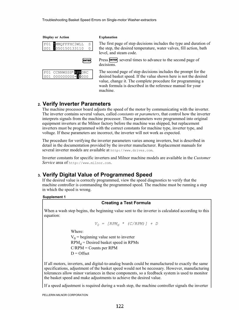
Troubleshooting Basket Speed Errors on Single-motor Washer-extractors
PELLERIN MILNOR CORPORATION
Display or Action Explanation
F01 TMMQFFFHC3WLL SS01 2050150133110 0
The first page of step decisions includes the type and duration ofthe step, the desired temperature, water valves, fill action, bathlevel, and steam code.
u Press u several times to advance to the second page ofdecisions.
F01 CCNNWSSS*RPMDRCS01 000000000-30000
The second page of step decisions includes the prompt for thedesired basket speed. If the value shown here is not the desiredvalue, change it. The complete procedure for programming awash formula is described in the reference manual for yourmachine.
2. Verify Inverter ParametersThe machine processor board adjusts the speed of the motor by communicating with the inverter.The inverter contains several values, called constants or parameters, that control how the inverterinterprets signals from the machine processor. These parameters were programmed into originalequipment inverters at the Milnor factory before the machine was shipped, but replacementinverters must be programmed with the correct constants for machine type, inverter type, andvoltage. If these parameters are incorrect, the inverter will not work as expected.
The procedure for verifying the inverter parameters varies among inverters, but is described indetail in the documentation provided by the inverter manufacturer. Replacement manuals forseveral inverter models are available at http://www.drives.com.
Inverter constants for specific inverters and Milnor machine models are available in the CustomerService area of http://www.milnor.com.
3. Verify Digital Value of Programmed SpeedIf the desired value is correctly programmed, view the speed diagnostics to verify that themachine controller is commanding the programmed speed. The machine must be running a stepin which the speed is wrong.
Supplement 1
Creating a Test Formula
When a wash step begins, the beginning value sent to the inverter is calculated according to thisequation:
V0 = [RPMd * (C/RPM)] + D
Where:V0 = beginning value sent to inverterRPMd = Desired basket speed in RPMsC/RPM = Counts per RPMD = Offset
If all motors, inverters, and digital-to-analog boards could be manufactured to exactly the samespecifications, adjustment of the basket speed would not be necessary. However, manufacturingtolerances allow minor variances in these components, so a feedback system is used to monitorthe basket speed and make adjustments to achieve the desired value.
If a speed adjustment is required during a wash step, the machine controller signals the inverter

PELLERIN MILNOR CORPORATION
to increase the basket speed by two RPMs or decrease the speed by one RPM at eachadjustment. These adjustments are made three seconds before the end of the programmedbasket On time (programming decision XXX). Because the speed is adjusted only one time perOn time period, formulas programmed with On times near the maximum may require severalminutes to achieve the programmed speed.
To give the machine sufficient time to achieve a steady speed state and to maintain that speedduring troubleshooting, it is often a good idea to program a special test formula. Totroubleshoot a speed error in a bath step, the test formula should contain a bath of moderate tolong duration with relatively brief basket On and Off times.1. For step 01, set the Type of Step to a Wash with basket rotation (T = 1 or 2).2. Set the Step Time to about 10 minutes (MMQ = 100).3. Do not set a temperature (FFF or CCC = 000).4. Program the machine to fill with cold water (C = 1) to a low level (LL = 04).5. Program no chemical injection (CC = 00).6. Program the speed in RPMs (e.g., RPM = 018) that is used in the erroneous production
formula.7. Program the basket On time to 20 seconds (XXX = 020) and the basket Off time to 3
seconds (YYY = 003).8. End the formula (E = 0).
Use the formula created in Supplement 1 or a similar formula to evaluate other possible sourcesof the problem.
Display or Action Explanation
6 With a step running in which the problem occurs, press this keyto view the speed diagnostics data. Press this key a second timeto close the speed diagnostics and display the normal run data.
10:38 F0005S03 02:370195 RPM=A029/D030
The top line of the speed diagnostics display is the same as whenthe formula is running normally. All speed diagnostics arecontained on the second line.
The leftmost number is the calculated digital counts value. Youcan determine the initial digital count for the programmed basketspeed from Table 1 and the equation below:
Cd = [RPMd * (C/RPM)] + D
Where:Cd = Desired digital counts valueRPMd = Desired basket speed in revolutions per minuteC/RPM = Counts per RPMD = Offset value

Troubleshooting Basket Speed Errors on Single-motor Washer-extractors
PELLERIN MILNOR CORPORATION
Table 1: Model-Specific Data
Machine ModelMaximumFrequency
MaximumWash RPM
Counts per RPM(C/RPM) Offset (D)
30022F_W30022X_W
155 40
36030F_S 18636030F_W 205
43
42026V_W 15542032F_S 17842032F_W 195
40
5
48040F_W 38 668036F_N
17032 7
15
Important: Values shown are subject to change without notice. Contact MilnorCustomer Service for verification.
Note 1: The counts and offset values are configurable in controller software WUWESME, used in single-motor E-style and divided cylinder washer-extractors. Contact your dealer or the Milnor service departmentfor assistance with these machines.
Display or Action Explanation
10:38 F0005S03 02:370195 RPM=A029/D030
The rightmost number of the bottom line indicates the desired(programmed) basket speed for this step. This value matches thevalue programmed in the wash formula.
10:38 F0005S03 02:370195 RPM=A029/D030
The middle number of the bottom line indicates the currentcalculated basket speed. Input/output board #1 determines thetime between each main pulley spoke passing the photoeye andreports this data to the processor board at each communicationcycle, which is usually more often than once per second. Theprocessor board filters the raw data from the input/output boardand displays the most recent valid value.
Tip: Large variations in the achieved RPM value are possible early in extract steps because the validrange includes values from 0 RPMs to the maximum extract RPM of the machine. Thesevariations have no effect on how the machine operates because of the frequency with which newdata is reported.
4. Verify Output Voltage of D-to-A BoardIf the microprocessor is displaying the correct calculated digital value, the next step is to verifythat the digital-to-analog board is putting out the appropriate signal voltage.1. Calculate the voltage of the signal that the D-to-A board should deliver to the inverter:
Vd = Cd / 409.5
Where:Vd = Desired voltageCd = Desired counts per RPM
For example, assume the machine is configured as a 48040F_W and the desired wash speedis 24 RPMs.a. From Table 1, we see that this machine model makes six counts per revolution and has an
offset of 15.

PELLERIN MILNOR CORPORATION
b. Calculate the desired counts for a basket speed of 24 RPMs:
Cd = [RPMd * (C/RPM)] + D
Cd = [24 RPMs * (6 counts per RPM)] + 15
159 = 144 + 15c. Calculate the desired voltage:
Vd = Cd / 409.5
0.3883 = 159 / 409.5
2. The DC voltage measured at the output terminals of the D-to-A board and at the analogvoltage input terminals (FV and FC on GPD 506 model inverters, or A1 and AC on F7 modelinverters) (shown in Figure 2) should match this number. You may see a small voltage dropfrom the D-to-A board to the inverter.

Troubleshooting Basket Speed Errors on Single-motor Washer-extractors
PELLERIN MILNOR CORPORATION
Figure 2: Measuring Control Voltage at D-to-A Board and Inverter
Digital-to-Analog Board LegendA. MTA-43 Pin 3B. MTA-43 Pin 8C. Inverter terminal A1D. Inverter terminal ACE. 2.2 microfarad capacitorF. Inverter terminal FVG. Inverter terminal FC
Inverter Analog Terminals for Yaskawa F7
Inverter Analog Terminals for Yaskawa GPD 506
.
Tip: The 2.2 microfarad capacitor between the analog input terminals (FV-FC on GPD 506; A1-AC on F7) filters noise from the input signal to the inverter. The machine may not operate asexpected if this capacitor is not present. When installing a replacement inverter, transfer thecapacitor as part of the procedure.
3. If this value is wrong at the D-to-A board, replace the board.

PELLERIN MILNOR CORPORATION
4. If the value is correct at the D-to-A board but wrong at the inverter, check the wiring betweenthe board and the inverter.
5. If the value is correct at both sets of terminals, troubleshoot the inverter.
5. Troubleshooting the Inverter
5.1. Verify Inverter Output Frequency—Use the inverter keypad to display the currentdesired frequency. This frequency should correspond to the input voltage according to thisequation:
Fd = (Vout / 10) * Fmax
Where:Fd = Desired frequencyVout = DC voltage output from D-to-A boardFmax = Maximum inverter frequency (see Table 1)
When the machine is running normally, the inverter display appears similar to one of theillustrations in Figure 3.
Figure 3: Typical Inverter Run Displays
Yaskawa GPD 506 Model Yaskawa F7 Model
LegendA. Desired frequencyB. Actual frequencyC. Actual amps
.
The specific procedure for viewing the inverter operating parameters varies among invertermodels.
• For Yaskawa F7 models, the actual and desired frequencies and the actual amperage arevisible on the normal operating display.
• For Yaskawa GPD 505 and 506 models, press the DSPL button on the inverter once toadvance from the Desired Frequency display to the Actual Frequency display.
5.2. Verify Inverter Output Amperage—Verify the current being delivered to the motor.Contact the Milnor® Customer Service department for guidelines on the acceptable amperage forthe conditions.
For Yaskawa GPD 505 and 506 models, press the DSPL button on the inverter once to advancefrom the Actual Frequency display to the Actual Amperage display.

Troubleshooting Basket Speed Errors on Single-motor Washer-extractors
PELLERIN MILNOR CORPORATION
6. Testing the MotorIf the procedures described earlier in this document do not eliminate the error, have the motortested by a reputable facility.
— End of BICWUT01 —
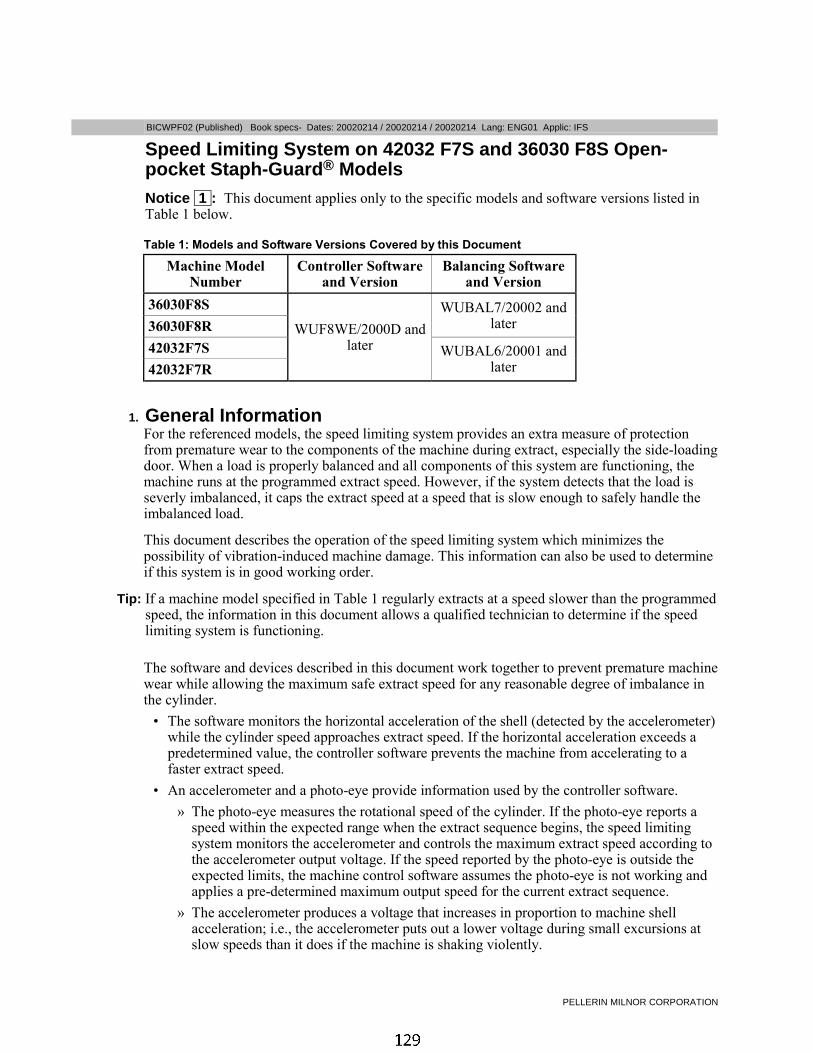
PELLERIN MILNOR CORPORATION
BICWPF02 (Published) Book specs- Dates: 20020214 / 20020214 / 20020214 Lang: ENG01 Applic: IFS
Speed Limiting System on 42032 F7S and 36030 F8S Open-pocket Staph-Guard® ModelsNotice 1 : This document applies only to the specific models and software versions listed inTable 1 below.
Table 1: Models and Software Versions Covered by this Document
Machine ModelNumber
Controller Softwareand Version
Balancing Softwareand Version
36030F8S
36030F8RWUBAL7/20002 and
later
42032F7S
42032F7R
WUF8WE/2000D andlater WUBAL6/20001 and
later
1. General InformationFor the referenced models, the speed limiting system provides an extra measure of protectionfrom premature wear to the components of the machine during extract, especially the side-loadingdoor. When a load is properly balanced and all components of this system are functioning, themachine runs at the programmed extract speed. However, if the system detects that the load isseverly imbalanced, it caps the extract speed at a speed that is slow enough to safely handle theimbalanced load.
This document describes the operation of the speed limiting system which minimizes thepossibility of vibration-induced machine damage. This information can also be used to determineif this system is in good working order.
Tip: If a machine model specified in Table 1 regularly extracts at a speed slower than the programmedspeed, the information in this document allows a qualified technician to determine if the speedlimiting system is functioning.
The software and devices described in this document work together to prevent premature machinewear while allowing the maximum safe extract speed for any reasonable degree of imbalance inthe cylinder.
• The software monitors the horizontal acceleration of the shell (detected by the accelerometer)while the cylinder speed approaches extract speed. If the horizontal acceleration exceeds apredetermined value, the controller software prevents the machine from accelerating to afaster extract speed.
• An accelerometer and a photo-eye provide information used by the controller software.
» The photo-eye measures the rotational speed of the cylinder. If the photo-eye reports aspeed within the expected range when the extract sequence begins, the speed limitingsystem monitors the accelerometer and controls the maximum extract speed according tothe accelerometer output voltage. If the speed reported by the photo-eye is outside theexpected limits, the machine control software assumes the photo-eye is not working andapplies a pre-determined maximum output speed for the current extract sequence.
» The accelerometer produces a voltage that increases in proportion to machine shellacceleration; i.e., the accelerometer puts out a lower voltage during small excursions atslow speeds than it does if the machine is shaking violently.

Speed Limiting System on 42032 F7S and 36030 F8S Open-pocket Staph-Guard® Models
PELLERIN MILNOR CORPORATION
To ensure the highest safe extract speeds, load the machine at or near its rated capacity wheneverpracticable. At the beginning of the extract sequence, the goods will distribute around the cylinderas illustrated in Figure 1. See “Determining Load Size” (BIWUUO01) for a complete explanationof how to achieve even distibution for maximum extract speed.
Figure 1: Load Distribution
Balanced and Imbalanced Loads Legend
A. Example of properlydistributed load
B. Example of imbalancedload
2. Mode 1: Photo-eye not Functioning ProperlyThe software on these machines allows the controller to determine if the load is sufficientlybalanced to run at the maximum programmed extract speed. This determination is based on atiming input from a photo-eye and an amplitude input from an accelerometer. See Note 1 andNote 2 for the locations of these components on the machine. The controller software verifies thatthe photo-eye is present and working by monitoring the photo-eye input during each drainsequence. If the pulse rate received from the photo-eye indicates that the basket is turning lessthan 40 RPMs or more than 100 RPMs for 10 seconds or more, the software determines that thephoto-eye is disabled.
Note 1: The accelerometer on 36-inch machines is located behind the right front frame member, accessibleby removing the right side access panel. The accelerometer on 42-inch machines is inside the stationarypart of the door latch mechanism (NOT on the door).
Note 2: The photoeye is mounted on a bracket inside the main drive pulley.
The photo-eye output goes to the balance board and the microprocessor. To verify the circuitbetween the photo-eye and the balance board, observe the SYNC light on the balance board (seeFigure 2). This light flashes with each pulse from the photo-eye to the balance board.
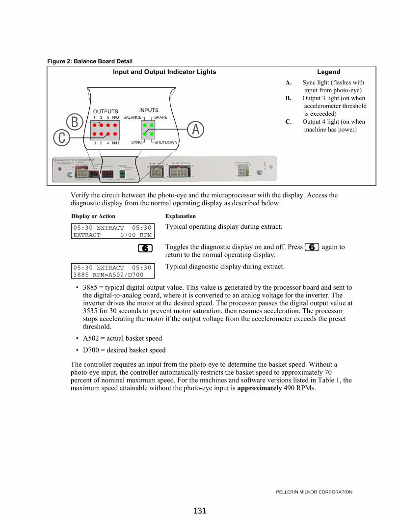
PELLERIN MILNOR CORPORATION
Figure 2: Balance Board Detail
Input and Output Indicator Lights Legend
A. Sync light (flashes withinput from photo-eye)
B. Output 3 light (on whenaccelerometer thresholdis exceeded)
C. Output 4 light (on whenmachine has power)
Verify the circuit between the photo-eye and the microprocessor with the display. Access thediagnostic display from the normal operating display as described below:
Display or Action Explanation
05:30 EXTRACT 05:30EXTRACT 0700 RPM
Typical operating display during extract.
6666 Toggles the diagnostic display on and off. Press 6 again toreturn to the normal operating display.
05:30 EXTRACT 05:303885 RPM=A502/D700
Typical diagnostic display during extract.
• 3885 = typical digital output value. This value is generated by the processor board and sent tothe digital-to-analog board, where it is converted to an analog voltage for the inverter. Theinverter drives the motor at the desired speed. The processor pauses the digital output value at3535 for 30 seconds to prevent motor saturation, then resumes acceleration. The processorstops accelerating the motor if the output voltage from the accelerometer exceeds the presetthreshold.
• A502 = actual basket speed
• D700 = desired basket speed
The controller requires an input from the photo-eye to determine the basket speed. Without aphoto-eye input, the controller automatically restricts the basket speed to approximately 70percent of nominal maximum speed. For the machines and software versions listed in Table 1, themaximum speed attainable without the photo-eye input is approximately 490 RPMs.

Speed Limiting System on 42032 F7S and 36030 F8S Open-pocket Staph-Guard® Models
PELLERIN MILNOR CORPORATION
Figure 3: Processor Board
Illustration Legend
A. Software chip withversion number sticker
B. Detail of MTA38C. Location of Pin 4
Figure 4: Balance Analog to Digital Board
Illustration Legend
A. Software chip withversion number sticker
B. Pin 9 of MTA85C. Pin 8 of MTA85
3. Mode 2: Photo-eye Present and FunctioningIf the photo-eye is functioning properly, the system (shown in Figure 5) functions as describedhere.
1. The balance board monitors the output voltage of the accelerometer.
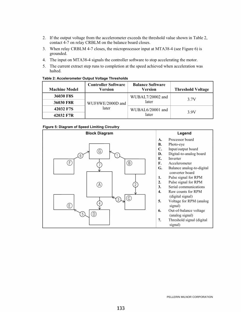
PELLERIN MILNOR CORPORATION
2. If the output voltage from the accelerometer exceeds the threshold value shown in Table 2,contact 4-7 on relay CRBLM on the balance board closes.
3. When relay CRBLM 4-7 closes, the microprocessor input at MTA38-4 (see Figure 6) isgrounded.
4. The input on MTA38-4 signals the controller software to stop accelerating the motor.
5. The current extract step runs to completion at the speed achieved when acceleration washalted.
Table 2: Accelerometer Output Voltage Thresholds
Machine ModelController Software
VersionBalance Software
Version Threshold Voltage
36030 F8S
36030 F8RWUBAL7/20002 and
later 3.7V
42032 F7S
42032 F7R
WUF8WE/2000D andlater WUBAL6/20001 and
later 3.9V
Figure 5: Diagram of Speed Limiting Circuitry
Block Diagram Legend
A. Processor boardB. Photo-eyeC. Input/output boardD. Digital-to-analog boardE. InverterF. AccelerometerG. Balance analog-to-digital
converter board1. Pulse signal for RPM2. Pulse signal for RPM3. Serial communications4. Raw counts for RPM
(digital signal)5. Voltage for RPM (analog
signal)6. Out-of-balance voltage
(analog signal)7. Threshold signal (digital
signal)

Speed Limiting System on 42032 F7S and 36030 F8S Open-pocket Staph-Guard® Models
PELLERIN MILNOR CORPORATION
Figure 6: Partial Schematic Diagram
Diagram Legend
A. Physically located on processor boardB. Physically located on balance analog to
digital board
— End of BICWPF02 —
MSSM0269AE/9525CV (1 of 4)
ÈSETTING THE UNIT OF MEASURE AND CALIBRATING ELECTRONIC WATER FLOWMETERS USED ONWASHER-EXTRACTORS AND TEXTILE MACHINES
Metered water (formerly called liquor ratio) is a feature which permits the formula developer to specify a quantityof water (as opposed to a liquor level) for each wash step. On washer-extractors, the quantity injected when theformula is run is the quantity specified in the formula. On textile machines, the quantity of water injected is propor-tional to the ratio of actual load weight entered by the operator and nominal weight specified in the formula.
Washer-extractors and textile machines furnished with metered water are equipped with a flowmeter to meas-ure the quantity of incoming water. The flowmeter is calibrated at the Milnor factory.
NOTE: Ensure that reuse water is free of lint and other solid contaminants which can become entangledin the flowmeter, causing it to malfunction.
ÊAbout These Procedures
ËWhy the Flowmeter Must be Calibrated —Flowmeters have a paddle wheel that rotates at a speed pro-portional to the speed of the passing water, sending pulses to an electronic counter. The number of pulses for a givenspeed of water will vary slightly from one flowmeter to another. The number of pulses for a given quantity of waterdepends on the size of the pipe the flowmeter is in. A 2" (51 mm) diameter pipe will have a much lower pulse countthan a 1" (25 mm) diameter pipe, for the same quantity. Calibration determines the ratio of pulses to quantity ofwater for the specific flowmeter and pipe. Initially, some unit of measure (e.g., pounds, gallons, kilograms, liters)must be chosen for calibrating. The Milnor factory uses pounds.
ËWhat Calibration Values are Required —The calibration values required by the microprocessor con-troller are counts per 100 and offset valve time. These values are entered in mode 5, Configure (see “PROGRAM-MING . . .” see Table of Contents).
Counts per 100 is the number of flowmeter counts resulting from injecting 100 units of water (pounds, gallons,kilograms, liters). Once the counts per 100 is established for a given unit of measure it may be converted to anyother unit. The unit of measure that counts per 100 is based on must also be used when programming formulas.
Offset Valve Time is the reduction in time that the water valve will remain open to admit the metered quantitycommanded in the formula. This adjustment compensates for the tendancy to overshoot the commanded quantitybecause of the time taken for the valve to close. The value is in tenths of seconds.
NOTE: The counts per 100 must be finalized before determining the offset valve time.
ÊSetting the Unit of Measure
ËWhen Setting the Unit of Measure is Required —Every machine equipped with electronic flowme-ters is calibrated at the Milnor factory and the flowmeter calibration label is marked with the counts per 100 andoffset valve time values. This label is located on the inside of the processor control board. A laundry desiring toprogram formulas in any unit other than pounds (the unit used by Milnor) must first convert the counts per 100shown on the calibration label to their preferred unit of measure and enter this value in the counts per 100 configuredecision.
B

ËConversion Procedure —Use the following formula to convert from pounds to another unit of measure:
Factory counts per 100 pounds x Multiplier listed below = New counts per 100
Desired UnitGallonsKilogramsLiters
Multiplier8.332.22.2
Example: Factory counts per 100 pounds = 0532Desired units = Liters
New counts per 100 liters = 0532 x 2.2 = 1170
NOTE: Contact the Milnor factory for any unit not listed if the conversion factor cannot be determined.
ÊCalibrating
ËWhen Calibration is Required —If configuration label is lost, merely re-enter the values listed on theconfiguration plate (or convert to the desired units). Recalibration is only required for replacement flowmeters or ifit is suspected that a flowmeter has lost its calibration as may eventually occur with use.
ËPreparations for Calibrating
INJURY AND MACHINE DAMAGE HAZARDS—Calibrating requires temporarily removingthe cylinder water inlet hose. This procedure must be performed only by qualified mainte-nance personnel, in strict compliance with published safety precautions.
Obtain a container large enough to hold 460 pounds (208 kilograms, 55 gallons, 208 liters). Establish a meansof accurately measuring the contents of the container (by weighing or determining volume).
Lock off machine power at the external disconnect switch, then remove the appropriate panels to gain accessto the machine’s water inlet piping. An internal hose connects the water inlet piping to the wash cylinder. Obtaineight feet (2.5 meters) of hose of the same diameter as the inter-nal hose. Disconnect the internal hose and install the temporaryhose such that incoming water will be injected into the measur-ing container. Make sure the hose is secured so it cannot jumpout of the container.
Taking care to keep bystanders away from the machine,restore machine power. In mode 5, Configure, enter the initialcounts per 100 value from Table A and enter 000 for the offsetvalve time.
Create a calibration formula consisting of one bath step.For this step, command no steam, cold water only, no chemicals,and whichever of the following water quantities is in the sameunits as the counts per 100 configure decision: 416 pounds, 189kilograms, 50 gallons, or 189 liters.
ÏTable A: Initial Counts per 100Cylinder
SizeInitial Value of Counts per 100
Pounds Kilograms Gallons Liters
36021/36026Consult Milnor factory42026
42031/42044
48032/48036 0540 1189 4498 1189
52038 0540 1189 4498 1189
60044 0225 0496 1874 0496
64046 0225 0496 1874 0496
72044/72058 0225 0496 1874 0496
SETTING THE UNIT OF MEASURE AND CALIBRATING ELECTRONIC WATER FLOWMETERS USED ONWASHER-EXTRACTORS AND TEXTILE MACHINES MSSM0269AE/9525CV (2 of 4)

ËSummary of Calibration Procedure —The calibration procedure is in two parts:
Part A. Determine the actual counts per 100 value. This is done by running the calibration formula, measur-ing the actual quantity injected (disregarding commanded quantity), reading the total counts, calculat-ing the actual counts per 100 units, entering this value in configure, and repeating the procedure untilconsistent results are achieved.
Part B. Determine the offset valve time. This is done by running the calibration formula, measuring the ac-tual quantity injected, determining any difference between actual and commanded quantity (becausethe water valves do not close instantaneously when commanded quantity is achieved) then adjustingthe offset valve time to eliminate discrepancies. This procedure is repeated until actual and com-manded quantities are equal.
ËPart A: Determining Counts per 100
When first running the calibration formula, the measuring container may overflow.
☞ Increase the number of counts per 100 to reduce the quantity of water injected.
1. Run the calibration formula. When the water valve closes, hold on the keypad and read the display.
04:38 F0001S01 04:00
01784 01350
The number on the lower left of the display (01784 in this example) is the totalcounts for this injection. Record this number.
2. Accurately measure the quantity of water injected. Record this value then drain the container.
3. Calculate the counts per 100 using the following formula:
Total countsActual quantity x 100 = Counts per 100
Example: Let’s say the actual quantity is 395 pounds. Then,
1784 395
x 100 = 452 counts per 100 pounds
4. Enter the result in the counts per 100 configure decision.
5. Repeat steps 1 through 4. The quantity injected should be slightly more than the commanded quantity and thenew counts per 100 should be close to the previously calculated value. Repeat, if necessary, until the countsper 100 value is consistent.
SETTING THE UNIT OF MEASURE AND CALIBRATING ELECTRONIC WATER FLOWMETERS USED ONWASHER-EXTRACTORS AND TEXTILE MACHINES MSSM0269AE/9525CV (3 of 4)

ËPart B: Determining Offset Valve Time1. Run the calibration formula.
2. Accurately measure the quantity of water injected, and compare this to the commanded quantity. Assumingactual is more than commanded, enter 010 (one second) into the offset valve time configure decision. (If ac-tual is less than commanded, repeat Part A). Drain the container.
3. Repeat steps 1 and 2 as required, adjusting the offset valve time until actual and commanded quantities areequal. This is a trial and error process.
4. Once testing is completed, lock power off at the machine’s external disconnect switch and restore the machineto its correct operational condition.
SETTING THE UNIT OF MEASURE AND CALIBRATING ELECTRONIC WATER FLOWMETERS USED ONWASHER-EXTRACTORS AND TEXTILE MACHINES MSSM0269AE/9525CV (4 of 4)

Pellerin Milnor has begun a manufacturing change which may affect how this manual applies toyour machine. European-style wiring is replacing conventional wiring methods in electricalboxes. Because this change is being implemented one machine model at a time, not all modelscurrently use European-style wiring.Because this wirirng change affects the chemical connections made in the field, it is important torefer to the correct manual section when making these connections. If your machine usesconventional wiring methods, refer to MSSM0262BE. If your machine uses European-stylewiring, refer to MSSM0262CE.The following list includes all washer-extractor models currently being shipped with European-style wiring and the date code of the day the change was implemented on that machine.
36021BWP --9714636030F8P --9717336030F8S --9736236030F8W --9711336026Q6P --9707336021Q6P --9707342026Q6P --9714642032F7W --9810742032F7P --9810736030F8J --9810742032F8J --9810736030Q6J --97146
BMP980025/98141

MSSM0262BE/9808AV (1 of 7)
ÈCONNECTING CHEMICAL SYSTEMS TO 100-FORMULA WASHER-EXTRACTORS AND TEXTILE MACHINES
Various methods, some standard and some optional, are available on all 100-formula washer-extractors andtextile machines, to accommodate any of the commonly used allied (non-Milnor) chemical systems. Use this sectionto help determine the best method of chemical injection and how to connect the chemical system. Always consultthe schematic manual before connecting chemical systems to the machine.
ELECTRIC SHOCK HAZARD—Contact with high voltage electricity will kill or seriouslyinjure you. Even with the Master Switch off and/or any emergency stop switches off,three-phase power and control circuit power are still present at several locations withinelectric boxes and electrical components.
INJURY AND DAMAGE HAZARDS—Improper wiring can cause machine to malfunc-tion, risking injury to personnel, damage to machine components, and damage togoods.
☞ Electrical and piping connections described in this section must be made only by qualified,authorized maintenance personnel.
☞ Lock off and tag out power at the external disconnect switches for the washer-extractor and forany chemical devices that provide power to the interpreter relay box (if furnished) before pro-ceeding.
☞ DO NOT rely merely on the information in this section when wiring. Consult all applicable elec-trical schematics.
☞ DO NOT reroute or rearrange any wires not specifically permitted by this instruction.☞ DO NOT connect a common wire to ground . Use the common terminal furnished.
ÊChemical Injection Methods Available(Item numbers correspond to those in FIGURE 1)
Ë1. Inject Signals —An inject signal is an electric potential that occurs in response to a programmed chemicalinjection. Five discrete signals (chemicals 1 through 5) are always furnished. If only these signals are furnished, theyare available at terminal strip TBS on BWP, QxP, and FxP models, and at Molex connector WCS on larger models.
Ten additional signals (chemicals 6 through 15) are optionally available. If these signals are furnished, then onBWP and QxP models, all 15 signals are available at terminal strips TBS and TBT. On BWP and QxP modelsfurnished with interpret relays and on all other models (whether or not interpret relays are furnished) all 15 signalsare available at terminal strip TBA.
Items 2 through 5 below operate off of inject signals. Disconnect the factory wired apparatus to use the injectsignal for any other low current apparatus that meets the electrical specifications provided elsewhere herein.
Ë2. Supply Injector —If a supply injector is furnished, the five electrically operated flush valves are wired toterminal strip TBS, WCS, or TBA (depending on model and options).
Ë3. Optional Interpret Relays —Interpret relay contacts have a higher current carrying capacity than injectsignals. The interpret relay coils are wired to TBA (see FIGURE 3). One set of contacts on each relay is wired toterminal strip TBB and connected to an internal power source. This power source may be replaced by an external,separately fused source, or merely disconnected, to provide potential-free (“dry”) contacts. Use interpret relays toactuate electrically operated apparatuses (e.g., pumps, valves) or provide potential-free signals for other controllers.
Ë4. Optional Pilot Air Valves —If these electrically operated valves are furnished, they are wired to terminalstrip TBS, WCS, or TBA, (depending on model and options) at the factory. Use pilot air valves to actuate air-operatedapparatuses (e.g., chemical valves).
Ë5. Optional Liquid Supply Valves —If these air-operated valves are furnished, they are tubed to the pilotair valves. Use these valves with pressurized liquid chemical delivery systems (e.g., ring main).
Ë6. Pumped Chemical Inlets —A five-port inlet is standard on rigid models and a 15 port inlet is optionalon all models. Use these valveless inlets only with systems that are not continuously pressurized and that deliverchemicals only when an injection is commanded (e.g., peristaltic pumps).
ËSequenced Chemical Injection (Chemwait) —When coupled with an allied chemical controller ofappropriate capability, the Chemwait feature permits a single chemical source to supply a bank of washer-extractorsby delaying chemical injection into one machine whenever that chemical source is currently supplying anothermachine. See “HOW CHEMWAIT WORKS . . .” (see Table of Contents).
ÊConnecting Apparatuses to Inject SignalsËElectrical Specifications— Inject signals provide a 110VAC, 50Hz or 120VAC, 60Hz potential. Each sig-nal can accommodate one apparatus not exceeding 37 milliamperes. Inject signals cannot be made potential-free.
COMPONENT DAMAGE HAZARD—Board components will burn out, requiring board re-placement if devices driven by inject signals do not meet the electrical specifications.(Pumps generally draw a higher current and will burn out board components.)
CONNECTING CHEMICAL SYSTEMS TO 100-FORMULA WASHER-EXTRACTORS AND TEXTILE MACHINES MSSM0262BE/9808AV (2 of 7)
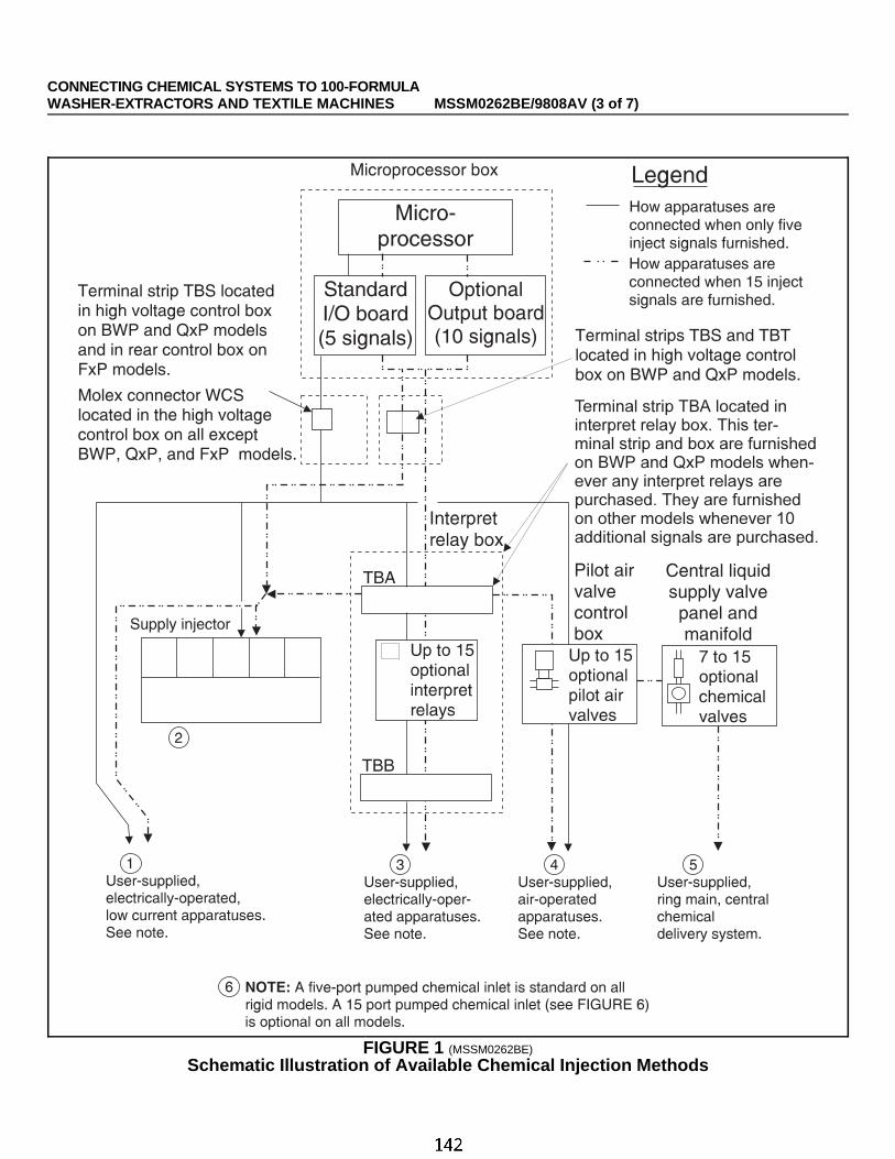
ÎFIGURE 1 (MSSM0262BE)
ÎSchematic Illustration of Available Chemical Injection Methods
CONNECTING CHEMICAL SYSTEMS TO 100-FORMULA WASHER-EXTRACTORS AND TEXTILE MACHINES MSSM0262BE/9808AV (3 of 7)

ËBWP, QxP and FxP Models With Five Signals Only —Acquire signals at terminal strip TBS, lo-cated in the high voltage control box on BWP and QxP models and in the rear control box on FxP models. Terminals1 through 5 are chemicals 1 through 5, respectively and terminal 8 is common. The specified voltage is enabledbetween the appropriate terminal and common whenever an injection is called for.
ËOther Models With Five Signals Only —Ac-quire signals at Molex connector WCS in the high voltage control box(see FIGURE 2). Pins 1 through 5 are chemicals 1 through 5 respec-tively and pin 7 is common. The specified voltage is enabled betweenthe appropriate pin and common whenever an injection is called for.
ËBWP and QxP Models With 15 Signals and NoInterpret Relays —Acquire all 15 signals at TBS and TBT in thehigh voltage control box. Terminals 1 through 7 on TBS and 1 through8 on TBT are chemicals 1 through 15 respectively. Terminal 8 on TBSis common. The specified voltage is enabled between the appropriateterminal of TBS or TBT and common, whenever a chemical injectionis called for.
ËOther Models With 15 Signals and No InterpretRelays —Acquire all 15 chemical signals and a manifold flush sig-nal at TBA (see FIGURE 3). Terminals A through Q on this terminalstrip are chemicals 1 through 15 respectively and Terminal R is theflush. Terminal TB1 provides a multi-pin common. The specified voltage is enabled between the appropriate termi-nal of TBA and common whenever a chemical injection or flush is called for.
ÊConnecting Apparatuses to Interpret RelaysËElectrical Specifications —The internal power source provides a 110VAC, 50Hz or 120VAC, 60Hz poten-tial. Each interpret relay can accommodate one apparatus, not exceeding 0.6 amperes. The total current drawn byall apparatuses must not exceed 10 amperes. When apparatuses are driven by external power, do not exceed 1ampere at 250VAC per relay contact.
COMPONENT DAMAGE HAZARD—Interpret relay contacts will fail, requiring relay re-placement if devices exceed the specified current load.
ËUsing Internal Power —When interpret relays (up to 15) are furnished, chemical signals are available at TBBin the interpret relay box. Terminals A through Q are chemicals 1 through 15 respectively. Terminal TB1 providesa multi-pin common. The specified voltage is enabled between the appropriate terminal of TBB and common when-ever a chemical injection is called for. As shown in FIGURE 3, terminal R of TBB is used to supply power internallyto one contact on each interpret relay.
ÎFIGURE 2 (MSSM0262BE)
ÎLocating WCS in High Voltage
CONNECTING CHEMICAL SYSTEMS TO 100-FORMULA WASHER-EXTRACTORS AND TEXTILE MACHINES MSSM0262BE/9808AV (4 of 7)

ËUsing External Power or Potential-Free Contacts —As shown in FIGURE 3, TBB, terminal R,which receives power via WCL, not only supplies power to the interpret relay contacts but also to the pumpedchemical inlet manifold flush valve and/or supply injector flush valves, if furnished. To disconnect the internalpower source, remove all of the wires from the left side of terminal R, but maintain the connections between theremoved wires. Make certain that any external power source connected to terminal R is separately fused.
Consider carefully the potential hazards of having more than one power source in a single enclosure.
If an external power source is wired to TBB, terminal R, then the voltage provided by this source is enabledbetween the appropriate terminal of TBB and the user-supplied common (not TB1) whenever a chemical injection iscalled for. If no power source is connected to TBB, terminal R, then a potential-free signal (contact closure) isenabled between the appropriate terminal (A through Q) of TBB and TBB, Terminal R, whenever an injection iscalled for.
ÎFIGURE 3 (MSSM0262BE)
ÎConnections Inside the Interpret Relay Box
CONNECTING CHEMICAL SYSTEMS TO 100-FORMULA WASHER-EXTRACTORS AND TEXTILE MACHINES MSSM0262BE/9808AV (5 of 7)

ÊPressurized Chemical SystemsThese systems use chemical valves on the machine to admit chemicals from pressurized lines (e.g., ring main
systems). The machine may be furnished with pilot air valves only, to which the customer may attach air-operatedchemical valves, or with pilot valves and chemical valves.
ËConnecting Air-Operated Chemical Valves to Pilot Air Valves —When chemical injection pi-lot valves are furnished, they are located in an air valve box dedicated to this function. Connect incoming com-pressed air where indicated in FIGURE 4. See the installationmanual for compressed air specifications. Pilot valves are ar-ranged from left to right, beginning with chemical 1, when fac-ing the connections, as shown in FIGURE 4 (however spacingvaries with the number of valves furnished). Pilot valve connec-tions accept 1/4" (6.3 mm) OD, 0.17" (4.3 mm) ID tubing. Tub-ing used by Milnor is rated for 310 psi (2.137 MPa) workingpressure at 72°F (22°C) and 1250 psi (8.618 MPa) minimumburst pressure at 73°F (23°C). If air-operated, liquid chemicalvalves are also furnished, these will be pre-connected to the pi-lot valves; however, these may be disconnected and the pilotvalves used to drive other devices, if desired.
ËConnecting Pressurized Liquid Chemical Lines to Air-Operated ValvesIf air-operated chemical valves are furnished, between seven valves (two standard flow plus five high flow)
and 15 valves will be supplied. Although each valve can be devoted to a separate chemical, the high flow valves areusually used to speed up injection when an extra large quantity of a chemical also injected via a standard flow valveis required (e.g., large doses of alkali in early heavy soil baths followed by smaller doses in later baths). Thus, thebasic seven-valve set normally accommodates five chemicals as shown in FIGURE 5. When air-operated chemicalvalves are furnished by Milnor, correspondingpilot air valves and associated air connectionsbetween pilot and chemical valves are also fur-nished. All chemicals are injected into a mani-fold which is automatically flushed with waterafter every injection.
Standard flow valve connections (1, 2, 3, 4,5, etc.) are 3/8" NPT. High flow valve connections(1L, 2L, etc.) are 1/2" NPT. Chemical pipingshould adhere to chemical system manufacturerspecifications. The water inlet for flushing is inter-nally connected to the main cold water inlet onsome machines. An external, 1/2" NPT connec-tion is required on other machines. Because theoutput relay-to-pilot valve wiring and the pilotvalve to chemical valve air connections vary withthe number and combination of valves furnished,its best to test each chemical output to determinewhich output (chemical 1, 2, 3, etc.) operateswhich valve (1, 1L, 2, 2L, etc.). See “MANUALMODE MENU FUNCTIONS . . .”
Compressedairin
Venttubes
Connectalliedair-operateddeviceshere
Chemical1 2 3 4 5
ÎFIGURE 4 (MSSM0262BE)
ÎArrangement of Pilot Air Valves
Towasher-extractor
Chemicals
1/2"HighFlowValve
3/8"StandardFlowValve
Flushingwaterin
fromPilotAirValve
Valves: Connectpressurizedchemicallineshere
1 2 3 4 51L 2L
ÎFIGURE 5 (MSSM0262BE)
ÎArrangement of Liquid Chemical Valves
CONNECTING CHEMICAL SYSTEMS TO 100-FORMULA WASHER-EXTRACTORS AND TEXTILE MACHINES MSSM0262BE/9808AV (6 of 7)

ÊPumped Chemical SystemsThese systems deliver chemicals to the machine intermittantly usually via peristaltic pumps. Inlets on the
machine must be unrestricted at all times (valveless). The 5 and 15 port pumped chemical inlets meet this require-ment.
ËRisk Associated With Pumped Chemical Systems —An inherent risk of this method of chemicalinjection is that concentrated chemicals can dribble into the machine after hours, when the machine is not in opera-tion, causing machine and/or linen damage. Because Milnor has no control over the design or installation of pumpedchemical systems, Pellerin Milnor Corporation accepts absolutely no responsibility for damage to its equip-ment or textiles therein, caused in this way. Much more information on this subject is provided in documentB2TAG86033, “Pumped Chemical Installation and Precautions.” Consult this document before connecting apumped chemical system.
ËConnecting Flushing Water to 15-PortInlets —Flushing water is required for 15-port inlets.It is internally piped to the incoming cold water inlet onsome machines. When not internally piped, a 1/2" NPTexternal water line must be connected where indicatedin FIGURE 6.
ÎFIGURE 6 (MSSM0262BE)
Î15-Port Pumped Chemical Inlet
CONNECTING CHEMICAL SYSTEMS TO 100-FORMULA WASHER-EXTRACTORS AND TEXTILE MACHINES MSSM0262BE/9808AV (7 of 7)

MSSM0262CE/9814AV (1 of 6)
ÈCONNECTING CHEMICAL SYSTEMS TO 100-FORMULA WASHER-EXTRACTORS AND TEXTILE MACHINESWITH EUROPEAN WIRING
Various standard and optional methods are available on all 100-formula washer-extractors and textile ma-chines, to accommodate any of the commonly used allied (non-Milnor) chemical systems. Use this section to helpdetermine the best method of chemical injection for your laundry and how to connect the chemical system. Alwaysconsult the machine schematic manuals before connecting chemical systems.
ELECTRIC SHOCK HAZARD—Contact with high voltage electricity will kill or seriouslyinjure you. Even with the Master Switch off and/or any emergency stop switches off,three-phase power and control circuit power are still present at several locations withinelectric boxes and electrical components.
INJURY AND DAMAGE HAZARDS—Improper wiring can cause the machine to malfunc-tion, risking injury to personnel, damage to machine components, and damage togoods.
☞ Electrical and piping connections described in this section must be made only by qualified,authorized maintenance personnel.
☞ Lock off and tag out power at the external disconnect switches for the washer-extractor and forany chemical devices that provide power to the interpret relay box (if furnished) before proceed-ing.
☞ DO NOT rely merely on the information in this section when wiring. Consult all applicable elec-trical schematics.
☞ DO NOT reroute or rearrange any wires not specifically described by this instruction.☞ DO NOT connect a common wire to ground . Use the common terminal furnished.

ÊChemical Injection Connection Methods AvailableËChemical Injection Output Signals
Five discrete signals, released in response to programmed chemical injections for chemicals 1 through 5, arefurnished standard on all washer-extractors. Ten additional signals (chemicals 6 through 15) are optionally availableon most machines. Often these start signals are used to operate other electrically-operated, low-voltage chemicalinjection devices like interpreter relays and pilot valves. These devices, in turn, are used to operate a higher voltagechemical injection device.
These signals, each capable of a maximum electrical load of 9VA at 120VAC, can be accessed at terminal stripTBA. Disconnect the factory wired apparatus to use these start signals for any other low current apparatuses.
ËLiquid Chemical Tube Barbed ConnectorsBarbed fittings, furnished standard on F-style machines, provide for the connection of tubes from remote
chemical supply injection systems. The F8P and F7P are furnished with six barbed connectors, while outerwearmachines are furnished with ten connectors.
One chemical injection output signal is required for each connector, and at least five are provided standard.
ËFive Compartment Flushing Chemical InjectorA five-compartment dry supply injector mounted externally on the washer-extractor is furnished standard on
most washer-extractors in lieu of a pumped chemical style system. The flushing chemical injector is offered option-ally on the Q style microprocessor machines and outerwear machines.
Each electrically operated flush valve located in a supply compartment is wired to terminal strip TBA and usesa chemical injection output signal.
ËOptional Interpret RelaysOne or more interpreter relays (up to 15) mounted in a control box are optionally available and connected to
the standard chemical injection outputs on washer-extractors. These relays can be used to operate other electrically-operated, high voltage chemical injection devices like pumps and valves.
These relays, each capable of a maximum electrical load of 1 ampere at 250VAC, have one set of contacts oneach relay wired to terminal strip TBA and connected to an internal power source. The internal power source may bereplaced by an external, separately fused source, or merely disconnected, to provide potential-free (“dry”) contacts.
ËOptional Pilot Air ValvesPilot air valves are optionally available to actuate air-operated chemical injection valves or other similar air-op-
erated devices supplied by others. A maximum of 15 of these normally-closed air valves are available and are con-nected to corresponding chemical injection output signals.
Each air-operated valve is wired to terminal strip TBA and uses a chemical injection output signal.
ËOptional Central Liquid Chemical Supply System/ValvesSeven air-operated chemical injection valves are optionally available for use with up to seven different chemi-
cals on most models. The system includes two 1/2" high flow and five 3/8" standard flow air-operated valves.Individual standard flow central liquid chemical valves are also optionally available up to a maximum of 8 addi-tional standard flow valves in the system for a maximum of 15 valves. Each individual valve includes the necessaryinterpreter relay and pilot valve.
Chemical injection valves are wired to terminal strip TBA and use a output signal, interpreter relay, and pilot valvefor each optional chemical valve. These valves are used with pressurized liquid chemical delivery systems like a ring main.
CONNECTING CHEMICAL SYSTEMS TO 100-FORMULA WASHER-EXTRACTORS AND TEXTILE MACHINESWITH EUROPEAN WIRING MSSM0262CE/9814AV (2 of 6)

ËOptional Peristaltic Pump ConnectionsUp to fifteen 1/2" barbed fittings for separate peristaltic hose connections are optionally available. Automatic
flush can be added optionally with peristaltic pump connections. The connections are provided standard with five chemical output signals, and additional signals must be added
to operate more than five peristaltic hose connections. These valveless inlets are used only with systems that are notcontinuously pressurized and that deliver chemicals only when an injection is commanded.
ËSequenced Chemical Injection (Chemwait)A chemical injection sequencer supplied by others interfaces with the machines to supply each machine with
chemicals one at a time. See “HOW CHEMWAIT WORKS . . .” (see Table of Contents).
ÊConnecting Apparatuses to Chemical Injection SignalsËElectrical Specifications— Inject signals provide a 110VAC, 50Hz or 120VAC, 60Hz potential. Each sig-nal can accommodate one apparatus not exceeding 37 milliamperes. Inject signals cannot be made potential-free.
COMPONENT DAMAGE HAZARD—Devices driven by injection output signals whichexceed electrical specifications will burn out board components, requiring board re-placement. (Pumps generally draw a higher current and will burn out board compo-nents.)
ËBWP and QxP Models With Five Signals Only —Acquire signals at terminal strip TBA, located inthe high voltage control box . Points 86 through 90 are chemicals 1 through 5, respectively, point 109 is flush, andpoint 6 is common. The specified voltage is enabled between the appropriate terminal and common whenever aninjection is called for.
ËFxP, FxS, and FxW Models With Five Signals Only —Acquire signals at terminal strip TBA in therear control box. Points 47 through 51 are chemicals 1 through 5, point 62 is flush, point 6 is common. In FxSmodels, point 63 is the soap chute. The specified voltage is enabled between the appropriate terminal and commonwhenever an injection is called for.
ËBWP and QxP Models With 15 Signals and No Interpret Relays —Acquire all 15 signals atTBA in the high voltage control box. Points 86 through 90 are 1 through 5 respectively and points 94 through 102are 6 through 14 respectively. Point 108 is chemical 15. Point 109 is flush. The specified voltage is enabled betweenthe appropriate terminal of TBA and common, whenever a chemical injection is called for.
ËFxP and FxW Models With 15 Signals and No Interpret Relays —Acquire all 15 signals atTBA in the high voltage control box. Points 52 through 61 are chemicals 6 through 15 respectively. The specifiedvoltage is enabled between the appropriate terminal of TBA, whenever a chemical injection is called for.
ËFxW Models With 15 Signals and Interpret Relays —Acquire all 15 signals at TBA in the highvoltage control box. Points 68 through 82 are 1 through 15 respectively. The specified voltage is enabled betweenthe appropriate terminal of TBA and common, whenever a chemical injection is called for.
CONNECTING CHEMICAL SYSTEMS TO 100-FORMULA WASHER-EXTRACTORS AND TEXTILE MACHINESWITH EUROPEAN WIRING MSSM0262CE/9814AV (3 of 6)

ÊConnecting Apparatuses to Interpret RelaysËElectrical Specifications —The internal power source provides a 110VAC, 50Hz or 120VAC, 60Hz poten-tial. Each interpret relay can accomodate one apparatus, not exceeding 0.6 amperes. The total current drawn by allapparatuses must not exceed 10 amperes. When apparatuses are driven by external power, do not exceed 1 ampereat 250VAC per relay contact.
COMPONENT DAMAGE HAZARD—Connecting devi ces which exceed the electricalspecifications can cause interpret relay contacts to fail, requiring relay replacement.
ËUsing Internal PowerWhen interpret relays (up to 15) are furnished, chemical signals are available at TBB in the interpret relay box.
Terminals A through Q are chemicals 1 through 15 respectively. Terminal TB1 provides a multi-pin common. Thespecified voltage is enabled between the appropriate terminal of TBB and common whenever a chemical injectionis called for. As shown in Figure 1, terminal R of TBB is used to supply power internally to one contact on eachinterpret relay.
ÎFIGURE 1 (MSSM0262CE)
ÎConnections Inside the Interpret Relay Box
CONNECTING CHEMICAL SYSTEMS TO 100-FORMULA WASHER-EXTRACTORS AND TEXTILE MACHINESWITH EUROPEAN WIRING MSSM0262CE/9814AV (4 of 6)

ËUsing External Power or Potential-Free ContactsAs shown in Figure 1, TBB, terminal R, which receives power via WCL, not only supplies power to the inter-
pret relay contacts but also to the pumped chemical inlet manifold flush valve and/or supply injector flush valves,if furnished. To disconnect the internal power source, remove all wires from the left side of terminal R, but maintainthe connections between the removed wires. Make certain that any external power source connected to terminal Ris separately fused.
Consider carefully the potential hazards of having more than one power source in a singleenclosure.
If an external power source is wired to TBB, terminal R, then the voltage provided by this source is enabledbetween the appropriate terminal of TBB and the user-supplied common (not TB1) whenever a chemical injectionis called for. If no power source is connected to TBB, terminal R, then a potential-free signal (contact closure) isenabled between the appropriate terminal (A through Q) of TBB and TBB, Terminal R, whenever an injection iscalled for.
ÊPressurized Chemical SystemsThese systems use chemical valves on the machine to admit chemicals from pressurized lines (e.g., ring main
systems). The machine may be furnished with pilot air valves only, to which the customer may attach air-operatedchemical valves, or with pilot valves and chemical valves.
ËConnecting Air-Operated Chemical Valves toPilot Air Valves —When chemical injection pilot valves arefurnished, they are located in an air valve box dedicated to thisfunction. Connect incoming compressed air where indicated inFigure 2. See the installation manual for compressed air specifi-cations. Pilot valves are arranged from left to right, beginningwith chemical 1, when facing the connections, as shown in Figure4 (however spacing varies with the number of valves furnished).Pilot valve connections accept 1/4" (6.3 mm) OD, 0.17" (4.3 mm)ID tubing. Tubing used by Milnor is rated for 310 psi (2.137MPa) working pressure at 72°F (22°C) and 1250 psi (8.618 MPa) minimum burst pressure at 73°F (23°C). If air-op-erated, liquid chemical valves are also furnished, these will be pre-connected to the pilot valves; however, these maybe disconnected and the pilot valves used to drive other devices, if desired.
Compressedairin
Venttubes
Connectalliedair-operateddeviceshere
Chemical1 2 3 4 5
ÎFIGURE 2 (MSSM0262CE)
ÎArrangement of Pilot Air Valves
CONNECTING CHEMICAL SYSTEMS TO 100-FORMULA WASHER-EXTRACTORS AND TEXTILE MACHINESWITH EUROPEAN WIRING MSSM0262CE/9814AV (5 of 6)

ËConnecting Pressurized Liquid Chemical Lines to Air-Operated Valves —If air-operatedchemical valves are furnished, between seven valves (two standard flow plus five high flow) and 15 valves will besupplied. Although each valve can be devoted to a separate chemical, the high flow valves are usually used to speedup injection when an extra large quantity of a chemical also injected via a standard flow valve is required (e.g., largedoses of alkali in early heavy soil baths followed by smaller doses in later baths). Thus, the basic seven-valve setnormally accommodates five chemicals as shown inFigure 3. When air-operated chemical valves are fur-nished by Milnor, corresponding pilot air valves and as-sociated air connections between pilot and chemicalvalves are also furnished. All chemicals are injectedinto a manifold which is automatically flushed withwater after every injection.
Standard flow valve connections (1, 2, 3, 4, 5,etc.) are 3/8" NPT. High flow valve connections (1L,2L, etc.) are 1/2" NPT. Chemical piping should adhereto chemical system manufacturer specifications. Thewater inlet for flushing is internally connected to themain cold water inlet on some machines. An external,1/2" NPT connection is required on other machines. Be-cause the output relay-to-pilot valve wiring and the pi-lot valve to chemical valve air connections vary withthe number and combination of valves furnished, it isbest to test each chemical output to determine whichoutput (chemical 1, 2, 3, etc.) operates which valve (1,1L, 2, 2L, etc.). See “MANUAL MODE MENUFUNCTIONS . . .”
ÊPumped Chemical SystemsThese systems deliver chemicals to the machine intermittently usually via peristaltic pumps. Inlets on the ma-
chine must be unrestricted at all times (valveless). The 5 and 15 port pumped chemical inlets meet this requirement.
ËConnecting Flushing Water to 15-PortInlets —Flushing water is required for 15-port inlets. It isinternally piped to the incoming cold water inlet on somemachines. When not internally piped, a 1/2" NPT externalwater line must be connected where indicated in FIGURE 6.
ËRisk Associated With Pumped ChemicalSystems —An inherent risk of this method of chemicalinjection is that concentrated chemicals can dribble into themachine after hours, when the machine is not in operation,causing machine and/or linen damage. Because Milnor hasno control over the design or installation of pumped chemi-cal systems, Pellerin Milnor Corporation accepts abso-lutely no responsibility for damage to its equipment or textiles therein, caused in this way. Much more infor-mation on this subject is provided in document B2TAG86033, “Pumped Chemical Installation and Precautions.”Consult this document before connecting a pumped chemical system.
Towasher-extractor
Chemicals
1/2"HighFlowValve
3/8"StandardFlowValve
Flushingwaterin
fromPilotAirValve
Valves: Connectpressurizedchemicallineshere
1 2 3 4 51L 2L
ÎFIGURE 3 (MSSM0262CE)
ÎArrangement of Liquid Chemical Valves
ÎFIGURE 4 (MSSM0262CE)
Î15-Port Pumped Chemical Inlet
CONNECTING CHEMICAL SYSTEMS TO 100-FORMULA WASHER-EXTRACTORS AND TEXTILE MACHINESWITH EUROPEAN WIRING MSSM0262CE/9814AV (6 of 6)

Definitions of Terms and Abbreviations
PELLERIN MILNOR CORPORATION
BIUUUK05 (Published) Book specs- Dates: 20050112 / 20050112 / 20050117 Lang: ENG01 Applic: CWW
Definitions of Terms and AbbreviationsAutoSpot—a control mechanism with which the operator can automatically align one cylinder
pocket of a divided cylinder machine with the loading doorsbath—a general term for any step of a wash formula during which the goods are exposed to
water with or without chemicals.CPU (central processing unit)—integrated circuit component, usually an Intel 8088 and its
ancillary devices, that interprets programming instructions and inputs to the microprocessorand provides outputs to other devices
CCW—counterclockwise cylinder rotation, as viewed from the load end; see also CWcentral liquid supply system—chemicals are constantly supplied to the machine under pressure;
valves on the machine open and close to regulate the flow of chemicals into the machinechecksum—one of several numbers generated by the control that represents the amount of data in
a specific memory area; any change in a checksum indicates that data has changedclean side—the side of a pass-through machine from which clean goods are unloaded after
processingcode, customer—the code that identifies the one of 1,000 possible owners of a batchcode, destination—the code that identifies the one of 64 (with the Miltrac™ controller) or one of
eight (if allied data pass) desired post-dry or no-dry destination of a batchcode, dry—code that identifies the one of 16 full-dry and 16 partial-dry cycles for a batchcode, formula—code that identifies the one of 16 basic wash formulas used to process a batchcode, goods—code that identifies the one of 256 goods classifications that describe a batch and
invoke any variations to the basic formula usedconfigure—microprocessor programming for various software and hardware options on the
machinecontrol—an electrical enclosure, usually housing a keypad, at which the user commands actions
and programs the machine; also includes all electromechanical devices on the machineinvolved with its operation; also referred to as “controller”
cooldown—used to gradually cool goods to prevent the setting of wrinkles. In a washer equippedwith the cooldown option (an additional level switch, a manual throttling valve, and an on/offcooldown water valve), this is a method of reducing the temperature of the goods throughrepeated partial draining and refilling with cold water. The cooldown rate is controlled by themanual throttling valve.
CPU—central processing unit; the main computer chip in a microprocessor control system thatprocesses data, as well as the board on which the CPU chip is mounted
customer code—see Code, customerCW—clockwise cylinder rotation direction as viewed from the front of the machinecycle—operations undertaken in a specific order to process goods; a cycle normally ends with the
device ready to accept another loadcylinder—the perforated basket inside the machine shell which contains the goods and is rotated
by the motorscylinder pocket—one of the two or three divisions of a divided cylinder washer-extractor into
which goods are loaded for processingdaisy chain—method of linking two or more serial type microprocessor controls with one four-
conductor shielded cable. All data passes via this cable, regardless of which machines arecommunicating.

Definitions of Terms and Abbreviations
PELLERIN MILNOR CORPORATION
default password—see Password, defaultdefault value—value used by the microprocessor control if no other value has been set by the
programmerdestination—area or zone of a laundry facility to which goods will be routed after drying, or
before pressing if the destination is a “no-dry” stationdestination code—see Code, destinationDIP switches—dual in-line package switches; a row of (usually six or eight) miniature switches
in a single housing used to permanently select or configure certain options on microprocessorboards; on Milnor® microprocessor controls these switches are used most often to specify thecommunications address for each machine in a system
discretionary data field—any field in the microprocessor control system that can be updatedthrough the keyboard or keypad; also, a machine configuration field, such as temperatureunits, that is not limited by hardware or equipment in the machine
display—the component by which the machine provides data to the operator; the component maybe one of several types, including vacuum fluorescent or liquid crystal (two lines of 20 alpha-numeric characters), color graphic liquid crystal (320 pixels by 240 pixels), or CRT monitor ofvarious resolutions.
door, manual—machine door which is opened and closed by hand, without power assistancedoor, power operated—machine door which is normally operated through electro-mechanical
controls rather than manually; usually, the machine must be energized for the door to operatedownload—process of transferring data, usually configuration and programming instructions,
from a machine to another machine or to a memory storage devicedrain speed—one of several ways to end a wash formula; goods are kept in motion at a speed
approximating the force of gravity (1g) until the operator is ready to discharge themdry code—see Code, dryEPROM—erasable programmable read-only memory; the portion of some Milnor®
microprocessor control systems used to store the fixed instructions (software) that determinehow the machine functions
extraction—the removal of excess water from goods discharged from the tunnel washerformula—instructions used by the machine control to operate motors, valves, and other
components during a standard cycleformula code—see Code, formulagoods—articles processed or conveyed by a machinehardware—electronic boards that control the machinehold code—function of a programmable output which answers the question, “If a hold condition
is encountered while this function is actuated, should the function continue to operate even ifits commanded parameters have not been achieved?”
inching—a control mechanism with which an operator can manually align one pocket of adivided cylinder machine with the loading doors
input, direct—signals that enter the processor board directly; direct inputs are provided byswitches on the machine, including limit switches, the Signal Cancel button, and theRun/Program keyswitch
input, standard—signals to the microprocessor controller that certain standard conditions exist;these inputs enter the processor board through the standard input/output board(s); include BagReady, Load Conveyor Ready, and remote customer and goods codes, etc.

Definitions of Terms and Abbreviations
PELLERIN MILNOR CORPORATION
jogging—intermittent rotation of the cylinder on certain Milnor® machines can be used todislodge goods from the cylinder wall after extraction, or to assist in discharging goods fromthe tilted cylinder, etc.
level switch—device that signals the controller when the bath liquor has reached a preset levelliquor—bath solution, usually consisting of water and chemicals at a specified temperature, for
processing goodsload—the amount of goods, measured by weight or pieces, that a machine normally handles
during a cycleloading device—in a system, this is the device which loads another device; example: a shuttle
may be the loading device for a dryerloading direction—the direction the goods are loaded into or onto a deviceMMQ—minutes, minutes, and quarter minutes (e.g., 043 = 4 minutes and 45 seconds); see also
SS and SSSmodel—designation of machine without regard to options; for most devices, the model includes
some dimensional representation of the effective machine sizemotor contactor box—enclosure containing the high voltage motor contactorspassword—three-character code entered to access or change values in certain display pages, used
to prevent unauthorized programming. The instructions for changing the password arecontained in a separate document sent only to the owner of the machine. See also Minipass
password, default—password when shipped from the Milnor® factory that automaticallyreplaces any field-programmed password after a failed Program Memory check, or if a newpassword has not been entered since the processor board memory was cleared or a newprocessor board was installed
permanent press—a fabric or finish which is heat-set after the article is manufactured tominimize wrinkling and to retain creases
program mode—mode which allows programming of wash formulas, dry cycles, and otherdiscretionary data; see also Run mode
pumped chemical supply system—chemicals flow into the machine when the machine controlor operator commands the pump to operate
reversing—one of several ways to end a wash formula; goods are kept in motion at wash speedby the rotating cylinder until the operator is ready to discharge them
run mode—mode of operation that allows devices to run automatically; see also Program modesoftware—fixed information contained in EPROMs (programming by Milnor®) or on disk files
that determines how a machine or computer operatessoil side—the side of a pass-through machine into which soiled goods are loaded for processingspray-down—a feature which allows the operator to facilitate loading the machine by spraying
the goods with water as they are loadedSS (SSS)—seconds, i.e., “SS” means two digits (usually 00-99 seconds), “SSS” means three
digits (usually 000-255 seconds); see also MMQstep timer—counts time for each individual step in a formula or dry codesupply injector—compartmented hopper into which chemicals are loaded before beginning a
wash cycle; the chemicals are flushed from the hopper compartments into the machineautomatically when commanded by the control
thermistor—temperature sensing device that varies its resistance to an electrical current withregard to temperature; used frequently in CBW® washers, washer-extractors, and textilemachines
Definitions of Terms and Abbreviations
PELLERIN MILNOR CORPORATION
three-wire circuit—circuit that provides control power for all machine functions; any of severalsafety devices in the three-wire circuit will open the circuit and stop machine operation if amalfunction is detected; once open, the three wire circuit can only be closed by manualintervention and then only if the condition that opened the circuit is rectified
Thermo-water—method of controlling incoming water temperature by modulating (alternatelyand oppositely opening and closing) the hot and cold water valves
toggle switch—one of several types of hand-operated switches with a single operating lever thatcan be moved to two or more positions (e.g., the Master switch)
trickle charge—process of slowly and continuously charging a microprocessor backup batteryduring machine operation to maintain a full charge
tumbling—goods are kept moving after the cycle is complete until the operator is ready todischarge them
washer-extractor—machine that both washes and extracts (spins the goods) to remove a largepercentage of the absorbed water
— End of BIUUUK05 —
Related Documents


