Infrastructure Access Reports Infrastructure: FH‐IWES Offshore Field Test Facilities Assessment and mitigation of Marine Corrosion in metallic components in Marine Renewable Energy (MRE) devices (Phase 2) User‐Project: CoMaRE Phase 2 CTC‐CENIM‐TECNALIA Marine Renewables Infrastructure Network Status: Final Version: 01 Date: 15‐Nov‐2013 EC FP7 “Capacities” Specific Programme Research Infrastructure Action

Welcome message from author
This document is posted to help you gain knowledge. Please leave a comment to let me know what you think about it! Share it to your friends and learn new things together.
Transcript
Infrastructure Access Reports
Infrastructure: FH‐IWES Offshore Field Test Facilities
Assessment and mitigation of Marine Corrosion in metallic components in Marine Renewable Energy
(MRE) devices (Phase 2) User‐Project: CoMaRE Phase 2
CTC‐CENIM‐TECNALIA
Marine Renewables Infrastructure Network
Status: Final Version: 01 Date: 15‐Nov‐2013
EC FP7 “Capacities” Specific Programme Research Infrastructure Action

Infrastructure Access Report: CoMaRE Phase 2
Rev. 01, 15‐Nov‐2013 Page 2 of 19
ABOUTMARINETMARINET (Marine Renewables Infrastructure Network for emerging Energy Technologies) is an EC‐funded network of research centres and organisations that are working together to accelerate the development of marine renewable energy ‐ wave, tidal & offshore‐wind. The initiative is funded through the EC's Seventh Framework Programme (FP7) and runs for four years until 2015. The network of 29 partners with 42 specialist marine research facilities is spread across 11 EU countries and 1 International Cooperation Partner Country (Brazil). MARINET offers periods of free‐of‐charge access to test facilities at a range of world‐class research centres. Companies and research groups can avail of this Transnational Access (TA) to test devices at any scale in areas such as wave energy, tidal energy, offshore‐wind energy and environmental data or to conduct tests on cross‐cutting areas such as power take‐off systems, grid integration, materials or moorings. In total, over 700 weeks of access is available to an estimated 300 projects and 800 external users, with at least four calls for access applications over the 4‐year initiative. MARINET partners are also working to implement common standards for testing in order to streamline the development process, conducting research to improve testing capabilities across the network, providing training at various facilities in the network in order to enhance personnel expertise and organising industry networking events in order to facilitate partnerships and knowledge exchange. The aim of the initiative is to streamline the capabilities of test infrastructures in order to enhance their impact and accelerate the commercialisation of marine renewable energy. See www.fp7‐marinet.eu for more details.
Partners Ireland
University College Cork, HMRC (UCC_HMRC) Coordinator
Sustainable Energy Authority of Ireland (SEAI_OEDU)
Denmark
Aalborg Universitet (AAU)
Danmarks Tekniske Universitet (RISOE)
France
Ecole Centrale de Nantes (ECN)
Institut Français de Recherche Pour l'Exploitation de la Mer (IFREMER)
United Kingdom
National Renewable Energy Centre Ltd. (NAREC)
The University of Exeter (UNEXE)
European Marine Energy Centre Ltd. (EMEC)
University of Strathclyde (UNI_STRATH)
The University of Edinburgh (UEDIN)
Queen’s University Belfast (QUB)
Plymouth University(PU)
Spain
Ente Vasco de la Energía (EVE)
Tecnalia Research & Innovation Foundation (TECNALIA)
Belgium
1‐Tech (1_TECH)
NetherlandsStichting Tidal Testing Centre (TTC)
Stichting Energieonderzoek Centrum Nederland (ECNeth)
Germany Fraunhofer‐Gesellschaft Zur Foerderung Der Angewandten Forschung E.V (Fh_IWES)
Gottfried Wilhelm Leibniz Universität Hannover (LUH)
Universitaet Stuttgart (USTUTT)
Portugal Wave Energy Centre – Centro de Energia das Ondas (WavEC)
Italy Università degli Studi di Firenze (UNIFI‐CRIACIV)
Università degli Studi di Firenze (UNIFI‐PIN)
Università degli Studi della Tuscia (UNI_TUS)
Consiglio Nazionale delle Ricerche (CNR‐INSEAN)
Brazil Instituto de Pesquisas Tecnológicas do Estado de São Paulo S.A. (IPT)
Norway Sintef Energi AS (SINTEF)
Norges Teknisk‐Naturvitenskapelige Universitet (NTNU)
Infrastructure Access Report: CoMaRE Phase 2
Rev. 01, 15‐Nov‐2013 Page 3 of 19
DOCUMENTINFORMATIONTitle Assessment and mitigation of Marine Corrosion in metallic components in Marine
Renewable Energy (MRE) devices (Phase 2)
Distribution Public
Document Reference MARINET‐TA2‐CoMaRE Phase 2
User‐Group Leader, Lead Author
David Fernández de Rucoba
CTC
Phone: +34 942 76 69 76 Email: [email protected]
User‐Group Members, Contributing Authors
Raúl Rodriguez Arias CTC Daniel de la Fuente CENIM Manuel Morcillo CENIM Jean Baptiste Jorcin TECNALIAMarta Tejero Gracia TECNALIAVirginia Madina ArreseTECNALIA
Infrastructure Accessed: FH‐IWES Offshore Field Test Facilities
Infrastructure Manager (or Main Contact)
Hanno Schnars
REVISIONHISTORYRev. Date Description Prepared by
(Name) Approved By Infrastructure
Manager
Status (Draft/Final)
00 25/10/2013 Draft for Approval DFR Draft
02 25/11/2013 Approved DFR Y Final
Infrastructure Access Report: CoMaRE Phase 2
Rev. 01, 15‐Nov‐2013 Page 4 of 19
ABOUTTHISREPORTOne of the requirements of the EC in enabling a user group to benefit from free‐of‐charge access to an infrastructure is that the user group must be entitled to disseminate the foreground (information and results) that they have generated under the project in order to progress the state‐of‐the‐art of the sector. Notwithstanding this, the EC also state that dissemination activities shall be compatible with the protection of intellectual property rights, confidentiality obligations and the legitimate interests of the owner(s) of the foreground. The aim of this report is therefore to meet the first requirement of publicly disseminating the knowledge generated through this MARINET infrastructure access project in an accessible format in order to:
progress the state‐of‐the‐art
publicise resulting progress made for the technology/industry
provide evidence of progress made along the Structured Development Plan
provide due diligence material for potential future investment and financing
share lessons learned
avoid potential future replication by others
provide opportunities for future collaboration
etc. In some cases, the user group may wish to protect some of this information which they deem commercially sensitive, and so may choose to present results in a normalised (non‐dimensional) format or withhold certain design data – this is acceptable and allowed for in the second requirement outlined above.
ACKNOWLEDGEMENTThe work described in this publication has received support from MARINET, a European Community ‐ Research Infrastructure Action under the FP7 “Capacities” Specific Programme.
LEGALDISCLAIMERThe views expressed, and responsibility for the content of this publication, lie solely with the authors. The European Commission is not liable for any use that may be made of the information contained herein. This work may rely on data from sources external to the MARINET project Consortium. Members of the Consortium do not accept liability for loss or damage suffered by any third party as a result of errors or inaccuracies in such data. The information in this document is provided “as is” and no guarantee or warranty is given that the information is fit for any particular purpose. The user thereof uses the information at its sole risk and neither the European Commission nor any member of the MARINET Consortium is liable for any use that may be made of the information.

Infrastructure Access Report: CoMaRE Phase 2
Rev. 01, 15‐Nov‐2013 Page 5 of 19
EXECUTIVESUMMARY Degradation due to the environment in marine devices and components is one of the main issues facing the offshore industry, and is an even greater issue in devices with a high degree of autonomous operation. In this report, an ongoing research and experimental project is presented. The project CoMaRE ‐Assessment and mitigation of marine Corrosion in metallic components in Marine Renewable Energy (MRE) devices‐ is focused in the assessment of the marine corrosion phenomena on metallic components in MRE devices from a practical point of view and in the evaluation of different candidate Corrosion Protection Techniques for metallic components. This project has an estimated duration of two years; therefore several phases are needed to achieve the desired results. During the second phase of the CoMaRE project the main activity has been the installation at Helgoland of the main part of tested coupons in field, and the preparation of tests in atmospheric condition in the CTC building. The specimens tested against corrosion cover a wide range of components used in devices such as mooring chains, fibre ropes, and steel plates, among others. The trials at the IWES‐Fraunhofer offshore field test facilities have been developed in the North Sea at the Helgoland Island (Germany) and the first results have been obtained. The cumulative environmental loads at this offshore test site differ considerably from the loads on these materials in laboratory tests. The materials are subjected to extreme offshore conditions: temperature fluctuations, increased UV radiation, exposure to seawater, biologically induced corrosion and mechanical loads. Mooring chains slide (with and without a Thermally Sprayed Aluminium coating –TSA‐), pieces of fibre ropes of different diameters, steel plates and polymer composite specimens are being tested at the offshore test rig in diverse marine conditions (tidal, splash and submerged) and atmospheric in the CTC´s facilities. Uncoated coupons have exhibited corrosion processes in splash zone; meanwhile all the coupons have shown appreciable marine growth in tidal and submerged zone. Composite tensile coupons have shown different behaviour, the ones with Multi Walled Carbon NanoTubes (MWCNT) dispersed in the polyester matrix have improved their resistance to degradation in the marine environment.

Infrastructure Access Report: CoMaRE Phase 2
Rev. 01, 15‐Nov‐2013 Page 6 of 19
CONTENTS
1 INTRODUCTION & BACKGROUND .................................................................................................................... 7
1.1 INTRODUCTION .................................................................................................................................................... 7 1.1.1 Task 1 Test plan detailed ............................................................................................................................. 7 1.1.2 Task 2 Field tests ......................................................................................................................................... 7 1.1.3 Task 3 Accelerated tests at laboratory ........................................................................................................ 7 1.1.4 Task 4 Laboratory analysis and correlation ................................................................................................ 8 1.1.5 Task 5 Preparation for 3rd Call ..................................................................................................................... 8 1.1.6 Task 6 Dissemination ................................................................................................................................... 8 1.2 DEVELOPMENT SO FAR .......................................................................................................................................... 8 1.2.1 Plan For This Access ..................................................................................................................................... 8
2 OUTLINE OF WORK CARRIED OUT .................................................................................................................... 9
2.1 SETUP ................................................................................................................................................................. 9 2.2 TESTS ............................................................................................................................................................... 11 2.2.1 Test Plan .................................................................................................................................................... 11 2.3 RESULTS ............................................................................................................................................................ 16 2.4 ANALYSIS & CONCLUSIONS ................................................................................................................................... 16
3 MAIN LEARNING OUTCOMES ......................................................................................................................... 16
3.1 PROGRESS MADE ............................................................................................................................................... 16 3.1.1 Progress Made: For This User‐Group or Technology ................................................................................. 17 3.1.2 Progress Made: For Marine Renewable Energy Industry .......................................................................... 17 3.2 KEY LESSONS LEARNED ........................................................................................................................................ 17
4 FURTHER INFORMATION ................................................................................................................................ 17
4.1 SCIENTIFIC PUBLICATIONS .................................................................................................................................... 17 4.2 WEBSITE & SOCIAL MEDIA ................................................................................................................................... 18
5 REFERENCES ................................................................................................................................................... 18
Infrastructure Access Report: CoMaRE Phase 2
Rev. 01, 15‐Nov‐2013 Page 7 of 19
1 INTRODUCTION&BACKGROUND
1.1 INTRODUCTIONDegradation due to the environment in marine devices and components is one of the main issues facing the offshore industry, and is an even greater issue in devices with a high degree of autonomous operation. This project is focused on the practical aspects of one degradation mechanism: corrosion of metallic components in Marine Renewable Energy devices. The selected testing infrastructure is unique in the MaRINET consortium and also across Europe, as it is located in a real offshore environment. As the main objectives of the project are to assess the marine corrosion mechanisms and to evaluate different candidate corrosion protection techniques, it is essential to carry out the tests in real extreme conditions. The technological and scientific support offered by the well‐experienced staff of the selected infrastructure is another reason to propose the access to these test facilities. Taking into account the scientific background of the User Group (UG), it is expected that as a result of this project, further lines of collaboration and research will be established between the institutions. In the following points the tasks for Phase 2 of the project are shown. These tasks have been done during the Call 2 access period (01/02/2013‐31/07/2013).
1.1.1 Task1TestplandetailedModification and coordination of test plan according to the changes in the samples to be tested at the FH IWES offshore field test facilities.
1.1.2 Task2FieldtestsThe objective of this task is testing several samples for assessing the marine corrosion rate at the offshore field test facilities. Below some examples that were described in the proposal for phase 2 are listed (non exhaustive):
• MCI (Marine Corrosivity Index) coupons [1]. • Bimetallic unions: i.e. plates • Bolts and tensors • Standards coupons with and without coatings. • Typical steel construction details (mooring systems: chains, fibre ropes...). • Coupons for accelerated tests.
The components really tested during phase 2 are included in section 1.1.6. Field tests also have included the development of atmospheric corrosion tests on the CTC building. These tests have the aim to correlate with the offshore marine tests. To achieve it, we will make use of climatic data of the different locations.
1.1.3 Task3AcceleratedtestsatlaboratoryOnce the field tests are finished, the samples will be analyzed applying standard practices in the Laboratory. These studies will mainly consist of chemical analysis of the corrosion products, weight loss evaluation and microstructural characterization of the samples by means of optical and scanning electron microscopy. A general morphological evaluation of the samples will also be carried out in order to identify the corrosion phenomena suffered.

Infrastructure Access Report: CoMaRE Phase 2
Rev. 01, 15‐Nov‐2013 Page 8 of 19
1.1.4 Task4LaboratoryanalysisandcorrelationFinally, and to some extent, depending on the time of exposure of the samples during Phase 3, some correlations with empirical models of corrosion rate will be done.
1.1.5 Task5Preparationfor3rdCallPreparation of the proposal for the 3rd call of MaRINET has been made. It’s needed to continue the project as the duration of the field test exceeds the time of the previous calls.
1.1.6 Task6DisseminationIt’s planned to attend to a European congress and write some scientific articles based on the experiences of this and the following phases. Expected results for the entire project:
Development of technical and practical solutions for mitigation of the degradation due to corrosion of marine metallic components for MRE devices.
Identification of the most appropriate Protection Technique for each Material/Component.
Dissemination of the corrosion rate in several (depending on the number of test sites) offshore areas.
Presentation and publication of results in international corrosion congresses and journals is intended.
To establish further lines of collaboration and research between the partners and the selected institution in marine corrosion assessment and mitigation.
1.2 DEVELOPMENTSOFAR
1.2.1 PlanForThisAccessThe tasks of the Phase 2 of the project are herein referred, and their development so far in this access is shown below:
1.2.1.1 Task1Testplandetailed This task has been completed during the previous phase, though it is an ongoing activity in order to fix minor differences between the planned and the real work at the test field. Also, some new tests have been added to the already planned tests.
1.2.1.2 Task2FieldtestsThe components tested so far include:
•Standards coupons without coatings. •Mooring systems: chains with and without coatings, fibre ropes with steel core. •Coupons of composite polyester with and without carbon nanotubes •Coupons of composite pre‐preg epoxy reinforced with fibre glass (new in this phase). •CLIMAT coupons to obtain different corrosivity indexes [1] (new in this phase). •Coupons for accelerated tests. •Reference un‐aged coupons.
1.2.1.3 Task3AcceleratedtestsatlaboratoryThis task is still in progress. Several coupons have been prepared for this task. Stress‐strain curves have been obtained from un‐aged composite coupons in the first phase. Besides, in this second phase, stress‐strain curves have been obtained for exposed composite coupons.

Infrastructure Access Report: CoMaRE Phase 2
Rev. 01, 15‐Nov‐2013 Page 9 of 19
1.2.1.4 Task4LaboratoryanalysisandcorrelationTo be done in the following phases of the Project.
1.2.1.5 Task5Preparationfor3rdCallThe proposal for the 3rd Call was prepared and it was approved and now the new activities have already started for this new Phase.
1.2.1.6 Task6DisseminationA poster titled “First experiences in the assessment and mitigation of marine corrosion in metallic components for Marine Renewable Energy devices” have been presented to EUROCORR 2013 (www.eurocorr2013.org) about first and second phase experiences. On the webpage of the CTC, a reference is included to this project.
2 OUTLINEOFWORKCARRIEDOUT
2.1 SETUP
The recent work continues the one started in CoMaRE Phase 1 [2].
Visit No.3 (2nd week of June/13)
The purpose of the visit was to place some new coupons and to check the ongoing corrosion tests at the Helgoland facilities. In Figure 2.1, several coupons are shown which have been prepared for exposure in the splash zone at the facility. The main activities were related to preparation and installation of new coupons, which have been transported to the island previously. 36 coupons obtained from slices of mooring chain (18 with and 18 without TSA) were installed. Another 6 coupons of composite pre‐preg material attached to 2 nylon supports were also screwed to the frames in 2 different marine environments. With the aim of obtaining the marine corrosivity index (MCI) in the splash zone a CLIMAT coupon was installed at the Fraunhofer IWES facilities. Finally, the exposed composite polyester coupons (with and without nanotubes) were removed and transported to the CTC, because their exposure time has finished. Installed coupons:
Splash Zone: 13 coupons. One of them is a composite epoxy group of coupons, formed of 3 samples each.
Tidal Zone: 13 coupons. One of them is a composite group of coupons, formed of 3 samples each.
Submerged zone: 12 coupons. They were placed below low tide.
In the Table 2.1 it’s summarized the number of different specimens situated on the rig after the visit.
Zone\Coupon type Composite Chain slides Fibre ropes Plates CLIMAT
Splash 1(3) 16 12 3 1
Tidal 1(3) 16 12 3 ‐
Submerged ‐ 16 ‐ 3 ‐
Table 2.1 Number of coupons fixed on the test rig for each exposition zone after the visit No. 3.

Infrastructure Access Report: CoMaRE Phase 2
Rev. 01, 15‐Nov‐2013 Page 10 of 19
Figure 2.1 Coupons of Phase 2 already located in the frame for testing in the splash zone (chain slides, composite prepreg, and a CLIMAT coupon).
Installation on the CTC building roof A wood framework with several composite coupons (pre‐preg and polyester) and a CLIMAT coupon has been installed on the roof of the CTC building. The 9 coupons were screwed to the wood framework with 45º degree angle with the vertical direction and oriented to the SW. They are isolated from the wood by a rubber washer. These composite coupons will be exposed to the atmospheric conditions for a 12 month period. In the Figure 2.2 the installation is observed. Installed coupons are summarized in Table 2.2 .
Zone\Coupon type Composite Polyester Composite Epoxy CLIMAT
Atmospheric 6 3 1
Table 2.2 Number of coupons fixed on the roof of the CTC building in Phase 2.
Figure 2.2 Composite coupons of Phase 2 already located in the wood frame for testing in atmospheric condition.

Infrastructure Access Report: CoMaRE Phase 2
Rev. 01, 15‐Nov‐2013 Page 11 of 19
2.2 TESTS
2.2.1 TestPlan During this Second Phase of the project, we have followed the previous test plan [2], which served as a basis for the tests which will be followed in the upcoming phases. The next phases are necessary in order to be able to obtain a more clear correlation between field tests and the accelerated ones at laboratory. As part of the development of the project, the three companies (Degima, Vicinay Cadenas and Itsaskorda) that were testing their components “in kind” continued the tests and in the case of Vicinay Cadenas provided a greater number of coupons than in the previous phase [2]. Similarly, CTC also prepared a new series of composite samples with the material provided by CENER in the research Alliance EERA Joint Programme on Wind Energy (http://www.eera‐set.eu/index.php?index=23 ). Therefore, the scope of this chapter is to detail the testing program for Phase 2, after the Phase 1 of the project and explain the system of control and traceability of the samples that will continue throughout the entire test program. It has been taken into account the changes between the Phase 1 and Phase 2, as the project has evolved. The information about these coupons has been registered into a database, to control the tests. The samples and coupons have been prepared, labelled, measured and registered in the CTC Laboratory before being exposed to each corrosion zone. One example of an archive of the database is shown in the Appendices. CENIM and TECNALIA will start their activities in the third phase.
2.2.1.1 Descriptionofthecoupons As previously described [2], the IWES Fraunhofer operates a marine corrosion tests facility in the inner side of the seawall of Helgoland’s harbour. The frame typically used to mount the samples is shown in the following figure:
Figure 2.3 Typical frame used to mount specimens.
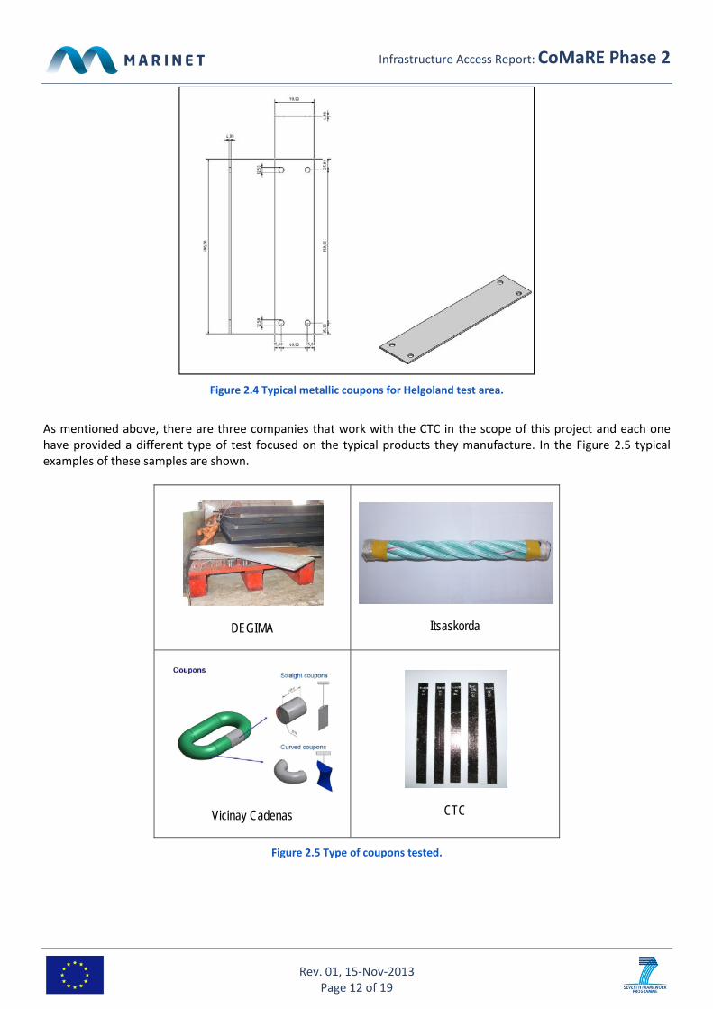
A plane is included below with the dimensions of the metal specimens which usually are bolted to the frame. In the southwest seawall of Helgoland’s harbour there are three different areas that can be classified attending the accepted criteria [3],[4] in marine corrosion: Splash zone, Tidal zone and Submerged zone.
Infrastructure Access Report: CoMaRE Phase 2
Rev. 01, 15‐Nov‐2013 Page 12 of 19
Figure 2.4 Typical metallic coupons for Helgoland test area.
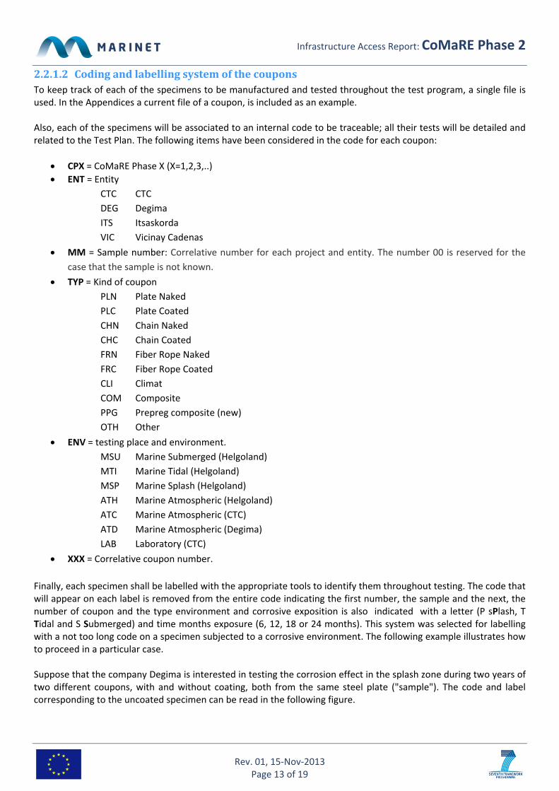
As mentioned above, there are three companies that work with the CTC in the scope of this project and each one have provided a different type of test focused on the typical products they manufacture. In the Figure 2.5 typical examples of these samples are shown.
DEGIMA
Itsaskorda
Vicinay Cadenas
CTC
Figure 2.5 Type of coupons tested.
Infrastructure Access Report: CoMaRE Phase 2
Rev. 01, 15‐Nov‐2013 Page 13 of 19
2.2.1.2 CodingandlabellingsystemofthecouponsTo keep track of each of the specimens to be manufactured and tested throughout the test program, a single file is used. In the Appendices a current file of a coupon, is included as an example. Also, each of the specimens will be associated to an internal code to be traceable; all their tests will be detailed and related to the Test Plan. The following items have been considered in the code for each coupon:
CPX = CoMaRE Phase X (X=1,2,3,..)
ENT = Entity
CTC CTC
DEG Degima
ITS Itsaskorda
VIC Vicinay Cadenas
MM = Sample number: Correlative number for each project and entity. The number 00 is reserved for the
case that the sample is not known.
TYP = Kind of coupon
PLN Plate Naked
PLC Plate Coated
CHN Chain Naked
CHC Chain Coated
FRN Fiber Rope Naked
FRC Fiber Rope Coated
CLI Climat
COM Composite
PPG Prepreg composite (new)
OTH Other
ENV = testing place and environment.
MSU Marine Submerged (Helgoland)
MTI Marine Tidal (Helgoland)
MSP Marine Splash (Helgoland)
ATH Marine Atmospheric (Helgoland)
ATC Marine Atmospheric (CTC)
ATD Marine Atmospheric (Degima)
LAB Laboratory (CTC)
XXX = Correlative coupon number.
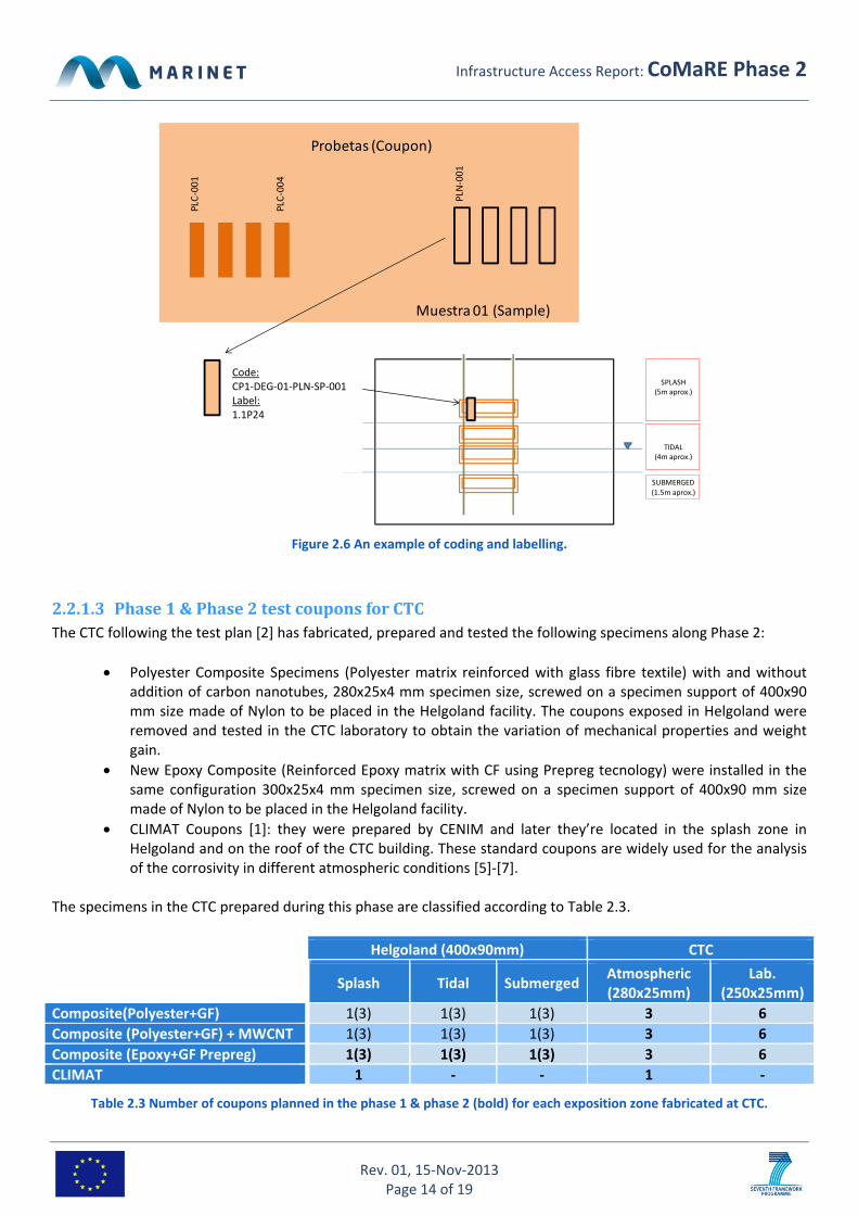
Finally, each specimen shall be labelled with the appropriate tools to identify them throughout testing. The code that will appear on each label is removed from the entire code indicating the first number, the sample and the next, the number of coupon and the type environment and corrosive exposition is also indicated with a letter (P sPlash, T Tidal and S Submerged) and time months exposure (6, 12, 18 or 24 months). This system was selected for labelling with a not too long code on a specimen subjected to a corrosive environment. The following example illustrates how to proceed in a particular case. Suppose that the company Degima is interested in testing the corrosion effect in the splash zone during two years of two different coupons, with and without coating, both from the same steel plate ("sample"). The code and label corresponding to the uncoated specimen can be read in the following figure.
Infrastructure Access Report: CoMaRE Phase 2
Rev. 01, 15‐Nov‐2013 Page 14 of 19
Figure 2.6 An example of coding and labelling.
2.2.1.3 Phase1&Phase2testcouponsforCTCThe CTC following the test plan [2] has fabricated, prepared and tested the following specimens along Phase 2:
Polyester Composite Specimens (Polyester matrix reinforced with glass fibre textile) with and without addition of carbon nanotubes, 280x25x4 mm specimen size, screwed on a specimen support of 400x90 mm size made of Nylon to be placed in the Helgoland facility. The coupons exposed in Helgoland were removed and tested in the CTC laboratory to obtain the variation of mechanical properties and weight gain.
New Epoxy Composite (Reinforced Epoxy matrix with CF using Prepreg tecnology) were installed in the same configuration 300x25x4 mm specimen size, screwed on a specimen support of 400x90 mm size made of Nylon to be placed in the Helgoland facility.
CLIMAT Coupons [1]: they were prepared by CENIM and later they’re located in the splash zone in Helgoland and on the roof of the CTC building. These standard coupons are widely used for the analysis of the corrosivity in different atmospheric conditions [5]‐[7].
The specimens in the CTC prepared during this phase are classified according to Table 2.3.
Helgoland (400x90mm) CTC
Splash Tidal SubmergedAtmospheric (280x25mm)
Lab. (250x25mm)
Composite(Polyester+GF) 1(3) 1(3) 1(3) 3 6
Composite (Polyester+GF) + MWCNT 1(3) 1(3) 1(3) 3 6
Composite (Epoxy+GF Prepreg) 1(3) 1(3) 1(3) 3 6
CLIMAT 1 ‐ ‐ 1 ‐
Table 2.3 Number of coupons planned in the phase 1 & phase 2 (bold) for each exposition zone fabricated at CTC.
Muestra 01 (Sample)
Probetas (Coupon)
PLC‐001
PLC‐004
PLN‐001
Código de la probetaCP1‐DEG‐01‐PLN‐SP‐001Etiqueta de la probeta
D01001
TIDAL (4m aprox.)
SUBMERGED(1.5m aprox.)
SPLASH (5m aprox.)
Code:CP1‐DEG‐01‐PLN‐SP‐001 Label: 1.1P24
Infrastructure Access Report: CoMaRE Phase 2
Rev. 01, 15‐Nov‐2013 Page 15 of 19
CTC has checked and verified the coupons of the rest of the companies before they were installed at Helgoland.
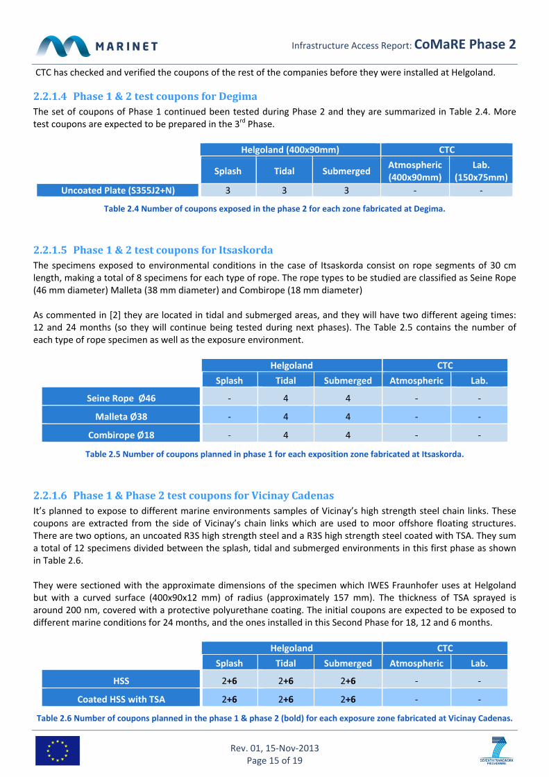
2.2.1.4 Phase1&2testcouponsforDegimaThe set of coupons of Phase 1 continued been tested during Phase 2 and they are summarized in Table 2.4. More test coupons are expected to be prepared in the 3rd Phase.
Helgoland (400x90mm) CTC
Splash Tidal Submerged Atmospheric (400x90mm)
Lab. (150x75mm)
Uncoated Plate (S355J2+N) 3 3 3 ‐ ‐
Table 2.4 Number of coupons exposed in the phase 2 for each zone fabricated at Degima.
2.2.1.5 Phase1&2testcouponsforItsaskordaThe specimens exposed to environmental conditions in the case of Itsaskorda consist on rope segments of 30 cm length, making a total of 8 specimens for each type of rope. The rope types to be studied are classified as Seine Rope (46 mm diameter) Malleta (38 mm diameter) and Combirope (18 mm diameter) As commented in [2] they are located in tidal and submerged areas, and they will have two different ageing times: 12 and 24 months (so they will continue being tested during next phases). The Table 2.5 contains the number of each type of rope specimen as well as the exposure environment.
Helgoland CTC
Splash Tidal Submerged Atmospheric Lab.
Seine Rope Ø46 ‐ 4 4 ‐ ‐
Malleta Ø38 ‐ 4 4 ‐ ‐
Combirope Ø18 ‐ 4 4 ‐ ‐
Table 2.5 Number of coupons planned in phase 1 for each exposition zone fabricated at Itsaskorda.
2.2.1.6 Phase1&Phase2testcouponsforVicinayCadenasIt’s planned to expose to different marine environments samples of Vicinay’s high strength steel chain links. These coupons are extracted from the side of Vicinay’s chain links which are used to moor offshore floating structures. There are two options, an uncoated R3S high strength steel and a R3S high strength steel coated with TSA. They sum a total of 12 specimens divided between the splash, tidal and submerged environments in this first phase as shown in Table 2.6. They were sectioned with the approximate dimensions of the specimen which IWES Fraunhofer uses at Helgoland but with a curved surface (400x90x12 mm) of radius (approximately 157 mm). The thickness of TSA sprayed is around 200 nm, covered with a protective polyurethane coating. The initial coupons are expected to be exposed to different marine conditions for 24 months, and the ones installed in this Second Phase for 18, 12 and 6 months.
Helgoland CTC
Splash Tidal Submerged Atmospheric Lab.
HSS 2+6 2+6 2+6 ‐ ‐
Coated HSS with TSA 2+6 2+6 2+6 ‐ ‐
Table 2.6 Number of coupons planned in the phase 1 & phase 2 (bold) for each exposure zone fabricated at Vicinay Cadenas.

Infrastructure Access Report: CoMaRE Phase 2
Rev. 01, 15‐Nov‐2013 Page 16 of 19
2.3 RESULTSThe main result of the project so far, is the assessment of the increment of weight and the variation of the strength of the polyester fibre reinforced composite material in unexposed and exposed sites; and the observations made at the field to all the exposed coupons after the first phase. Currently, we haven’t developed any correlations between accelerated tests and the field ones, mainly because field tests which require a longer time span haven’t finished. The results (maximum stress and maximum deformation) of tensile testing of the unexposed vs. exposed coupons are presented in 18[8]. The tensile tests followed the EN ISO 527‐1 Standard [9]. The aged coupons had been exposed during 8,5 months in the three environmental conditions (splash, tidal and submerged) and they were tested dry. The fouling of the coupons was cleaned before testing. The results of these tests showed less environmental effect in composite material with MWCNT addition. The net weight gain was also measured in both type of polyester coupons and the results showed less gain in the case of MWCNT addition, in general. Particularly, this effect was more noticeable in tidal zone. In the last inspection, it was found that several specimens showed signs of oxidation and rusting processes as it can be observed in [8]. Marine growth was also observed in the tidal and submerged zone.
2.4 ANALYSIS&CONCLUSIONSFrom the visual inspection of the coupons and the tensile tests we conclude that the corrosion/degradation processes have developed in the specimens located in the different zones, more significantly in uncoated ones. In fact, submerged and tidal specimens also showed marine growth. Sorted by type of coupon:
1. Composite polyester coupons: no major surface chalking or degradation damage on field test, some whitening around fibre glass was observed in coupons without MWCNT addition. In Submerged zone specimens showed marine growth, but less than metallic coupons. However, the composite coupons were more covered by algae than metallic ones in the tidal zone. The addition of multi‐walled carbon nanotubes (MWCNT) has decreased the mean loss of mechanical properties due to natural weathering in all the marine environments. This loss is more relevant in submerged coupons, so it could be related with algae and microbial activity. The effect of unsealed edges of the coupons has been discussed, but it has been studied that the sealed edges don´t have any relevant effect on water gain [10], and in some cases, scratches, erosion and damages of the composite could appear during the MRE device service life [11]. Generally, less weight gain was also observed in the case of coupons with MWCNT.
2. Steel plate coupons: showed noticeable rusting and fouling (in submerged and tidal), as expected.
3. Fibre rope coupons: marine growth was observed in the tidal zone and some rusting in the metal core of the edges of the ropes.
4. Coupons from the offshore chain: clear rusting in uncoated ones, while the coated ones showed relevant degradation of the coating (TSA), specially in the tidal and submerged zone.
3 MAINLEARNINGOUTCOMES
3.1 PROGRESSMADEAll the planned coupons in the test plan have been screwed to the marine test rig and to the atmospheric test rig. We have exposed all the coupons planned by the UG for this phase. The UG have already agreed to prepare them for

Infrastructure Access Report: CoMaRE Phase 2
Rev. 01, 15‐Nov‐2013 Page 17 of 19
the next phases. Laboratory tests haven’t started yet but it’s possible to carry them during the next phases. Some results in composite polyester coupons have been obtained, showing improved durability of the addition of MWCNT.
3.1.1 ProgressMade:ForThisUser‐GrouporTechnologyIn this technology new materials have been tested in the marine environment to check their behaviour. In this phase we have continued the testing already initiated and new coupons were also installed. We will have to wait to obtain more results, basically because corrosion testing takes time to give relevant information, especially in coated coupons.
3.1.1.1 NextStepsforResearchorStagedDevelopmentPlan–Exit/Change&Retest/Proceed?As we have planned, the next steps and further results are in the near future for the Third Phase, as some members the UG are going to start their testing in the different facilities. New environmental tests have started in offshore and atmospheric marine condition. Several coupons will be removed and analyzed at laboratory in the next phases
3.1.2 ProgressMade:ForMarineRenewableEnergyIndustryThe UG have started testing different materials used in MRE devices, and so far the beneficial effect of coating in the chains has been observed. The fibre rope has also been affected by fouling and corrosion. Also the marine growth must be considered, as it effect is not only due to increase in weight over the structure and it’s not only applied to steel structures. Both mooring systems are commonly used as a solution for mooring the MRE devices. Therefore, these results will be interesting for the durability of MRE devices.
3.2 KEYLESSONSLEARNED
Created a test plan taking account of possible problems.
The collaboration with companies to give coupons “in kind” is interesting.
Preparing the coupons to be strongly attached in the testing rig is important for field tests.
Coating affects significantly the corrosion and fouling process in offshore chains and fibre ropes.
Oxidation of the metallic core of the fibre ropes has been observed.
Composite coupons are also affected by marine growth, including their mechanical properties.
The addition of MWCNT has improved the durability of composite polyester coupons.
4 FURTHERINFORMATION
4.1 SCIENTIFICPUBLICATIONSList of any scientific publications made (already or planned) as a result of this work (in all the phases of the project):
EUROCORR 2013: Poster in EUROCORR 2013 Congress (www.eurocorr2013.org) titled “First experiences in the assessment and mitigation of marine corrosion in metallic components for Marine Renewable Energy devices” was shown.
THETIS Energy Marine Renewable 2013: A Poster session titled “Assessment and mitigation of marine corrosion in metallic components in Marine Renewable Energy devices: first experiences from offshore field tests in the North Sea” about the first phase work was presented (http://www.thetis‐emr.com/articles/62‐THETIS_MRE_chooses_Brest_to_power_ahead_in_2013 ).
Future Participation in European Coating Conferences, Marine Coatings is proposed to be held in 4‐5 March 2014 in Düsseldorf (http://www.european‐coatings.com/Events/European‐Coatings‐CONFERENCES)
Infrastructure Access Report: CoMaRE Phase 2
Rev. 01, 15‐Nov‐2013 Page 18 of 19
Planned: 2 papers on corrosion and degradation during the following phases.
4.2 WEBSITE&SOCIALMEDIA Website: http://ctcomponentes.es/en/comare‐2/#/[10]50/1/0 In the news: YouTube Link(s): LinkedIn/Twitter/Facebook Links: Online Photographs Link:
5 REFERENCES
[1] ASTM Standard G116 – 99 (2010) “Standard Practice for Conducting Wire‐on‐Bolt Test for Atmospheric Galvanic Corrosion”. ASTM International, West Conshohocken, PA, www.astm.org. 2010.
[2] Gorrochategui I., Rodríguez Arias R., Fernández D., De la Fuente D., Morcillo M., Jorcin J.B., Azcarate I., Madina V., Schnars H., “Assessment and mitigation of Marine Corrosion in metallic components in Marine Renewable Energy (MRE) devices (Phase 1)”. CTC‐CENIM‐TECNALIA, Infrastructure owner Fraunhofer IWES. MARINET Infrastructure Access Report, CoMaRE Phase 1. March 2013. Available in: http://www.fp7‐marinet.eu/public/docs/CoMaRE_Phase1_Access_Period%201.pdf .
[3] Baboian R. et alt., “Corrosion Test and Standards, Application and Interpretation”. Section V Testing in Environments, Chapter 30 “Seawater” Shifler D.A., Aylor D.M. 2nd Edition, ASTM International West Conshohocken, PA, www.astm.org. 2005
[4] Stenzel V., Plagemann P., Momber A.W., Schneider M., “Combined Field‐Laboratory Studies on Corrosion Protection for Offshore Windenergy Towers.” 4th Intern. Symp. on Protective Coatings, Bombay, 2006.
[5] Rivero S., Chico B., de la Fuente D., Morcillo M., “Atmospheric corrosion of low carbon steel in a polar marine environment. Study of the effect of wind regime. ” (in Spanish) Rev. de Metalurgia, 43(5), pp. 370‐383. September 2007.
[6] Morcillo M., Otero E., Chico B., de la Fuente D., “Atmospheric corrosion studies in a decommissioned nuclear power plant”. Nuclear Power, Pavel Tsvetkov (Ed.), ISBN: 978‐953‐307‐110‐7, InTech, 2010. Available from: http://www.intechopen.com/books/nuclear‐power/atmospheric‐corrosion‐studies‐in‐a‐retired‐nuclear‐powerplant .
[7] Klassen R.D., Roberge P.R., Lenard D.R., Blenkinsop G.N., "Corrosivity Patterns Near Sources of Salt Aerosols," Outdoor Atmospheric Corrosion, ASTM STP 1421, H. E. Townsend, Ed., American Society for Testing and Materials International (ASTM), West Conshohocken, PA, www.astm.org. 2002.
[8] Fernández D., Rodríguez R., Gorrochategui I., “First experiences in the assessment and mitigation of marine corrosion in metallic components for Marine Renewable Energy devices,” EUROCORR 2013 Congress, European Corrosion Congress, Poster. September 2013.
Infrastructure Access Report: CoMaRE Phase 2
Rev. 01, 15‐Nov‐2013 Page 19 of 19
[9] BS EN ISO 527‐1 Plastics‐Determination of tensile properties. 1996.
[10] Miller P.H., “Durability of Marine Composites: A Study of the Effects of Fatigue in Fibreglass in the Marine Environment”. Chapter 6: Coupon Testing Programme, Berkeley, University of California. April 2000.
[11] Wood R.J.K., Bahaj A.S., Turnock S.R., Wang L. And Evans M., “Tribological design constraints of marine renewable energy systems”, Phil. Trans. R. Soc. A 368, 4807–4827. September 2010.
Related Documents