Overview 1 Name and Function of Each Unit 2 Common Basic Operations 3 Range and Bearing Measurement Methods 4 Basic Operation of the Radar 5 Target Tracking and AIS 6 True and False Echoes on Display 7 Functions of the ECDIS (Option) 8 Route Planning 9 Route Monitoring 10 Monitoring a Dragging Anchor 11 Automatic Sailing (Option) 12 Operating a Chart (Option) 13 Creating a User Chart/ Updating a Chart Manually 14 Logbook 15 Setting Up Screen View 16 Setting Up Alerts 17 Setting Up the Operation Mode 18 Adjusting and Setting Up Equipment (for Services) 19 Playing Back Data Recorded During Navigation [Playback] 20 Maintenance & Inspection 21 Failures and After-Sale Services 22 About Disposal 23 Specifications 24 Radar Antenna Block Diagrams APP A Alert List APP B Setting the Interswitch APP C Menu List and Materials APP D JMR-7230-S3/S JMR-7225-7X3/9X3/6X/9X/6XH JMR-7210-6X/6XH JMR-7272-S JMR-7282-S/SH JMR-9230-S3/S JMR-9225-7X3/9X3/6X/9X/6XH JMR-9210-6X/6XH JMR-9272-S JMR-9282-S/SH Marine Radar Equipment Instruction Manual <Basic Operation>

Welcome message from author
This document is posted to help you gain knowledge. Please leave a comment to let me know what you think about it! Share it to your friends and learn new things together.
Transcript
Overview 1 Name and Function of Each Unit 2 Common Basic Operations 3 Range and Bearing Measurement Methods 4 Basic Operation of the Radar 5 Target Tracking and AIS 6 True and False Echoes on Display 7 Functions of the ECDIS (Option) 8 Route Planning 9 Route Monitoring 10 Monitoring a Dragging Anchor 11 Automatic Sailing (Option) 12 Operating a Chart (Option) 13 Creating a User Chart/ Updating a Chart
Manually 14
Logbook 15 Setting Up Screen View 16 Setting Up Alerts 17 Setting Up the Operation Mode 18 Adjusting and Setting Up Equipment (for
Services) 19 Playing Back Data Recorded During
Navigation [Playback] 20 Maintenance & Inspection 21 Failures and After-Sale Services 22 About Disposal 23 Specifications 24 Radar Antenna Block Diagrams APP A
Alert List APP B
Setting the Interswitch APP C
Menu List and Materials APP D
JMR-7230-S3/S JMR-7225-7X3/9X3/6X/9X/6XH JMR-7210-6X/6XH JMR-7272-S JMR-7282-S/SH JMR-9230-S3/S JMR-9225-7X3/9X3/6X/9X/6XH JMR-9210-6X/6XH JMR-9272-S JMR-9282-S/SH
Marine Radar Equipment
Instruction Manual
<Basic Operation>

i
PREFACE
Thank you for purchasing the JRC Multi Function Display JMR-7200/JMR-9200 Series.
This equipment meets the performance standards of the IMO (International Maritime
Organization) and the IHO (International Hydro graphic Organization), and serves to improve
safety, reduce fuel combustion, concentrate voyage information as the main device of the INS
(Integrated Navigation System).
For the best operation, read this manual thoroughly before use.
Keep this manual in a convenient place for future reference.
Make use of this manual when experiencing operation difficulties.
The LCD of this equipment uses thin film transistors (TFT). If some pixels on the screen
are not clear, the color is different, or the screen is brighter than usual, it is not because of
defect, instead it is because of inherent characteristic of the TFT display technology.
The information in this manual is subject to change without notice at any time.
7ZPNA4446H

ii
Safety Cautions
Cautions for High Voltage High voltages, ranging from several hundreds to tens of thousands of volts, are used in electronic
apparatus, such as radio and radar instruments. These voltages are totally harmless in most
operations. However, touching a component inside the unit is very dangerous. (Any person other
than authorized service engineers should not maintain, inspect, or adjust the unit.)
High voltages on the order of tens of thousand volts are most likely to cause instant deaths from
electrical shocks. At times, even voltages on the order of several hundred volts could lead to
electrocution. To defend against electrical shock hazards, don't put your hand into the inside of
apparatus.
When you put in a hand unavoidably in case of urgent, it is strongly suggested to turn off the
power switch and allow the capacitors, etc. to discharge with a wire having its one end positively
grounded to remove residual charges. Before you put your hand into the inside of apparatus,
make sure that internal parts are no longer charged. Extra protection is ensured by wearing dry
cotton gloves at this time. Another important precaution to observe is to keep one hand in your
pocket at a time, instead of using both hands at the same time. It is also important to select a
secure footing to work on, as the secondary effects of electrical shock hazards can be more
serious. In the event of electrical shocks, disinfect the burnt site completely and obtain medical
care immediately.
Precautions for Rescue of Victim of Electric Shock
When a victim of electric shock is found, turn off the power source and ground the circuit
immediately. If this is impossible, move the victim away from the unit as quick as possible without
touching him or her with bare hands. He or she can safely be moved if an insulating material
such as dry wood plate or cloth is used.
It is necessary to perform first aid immediately.
Breathing may stop if current flows through the respiration center of brain due to electric shock. If
the electric shock is not large, breathing can be restored by artificial respiration. A victim of
electric shock looks pale and his or her pulse may become very weak or stop, resulting in
unconsciousness and rigidity at worst.
iii
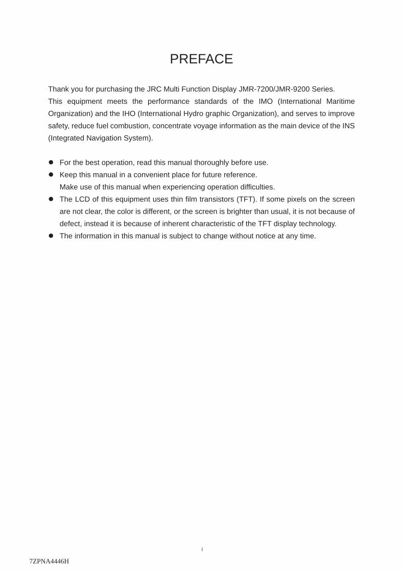
Emergency Measures
Method of First-Aid Treatment
Precautions for First-Aid Treatments
Apply artificial respiration to the person who collapsed, minimizing moving as much as
possible avoiding risks. Once started, artificial respiration should be continued rhythmically.
(1) Refrain from touching the patient carelessly as a resultof the accident; the first-aider
could suffer from electrical shocks by himself or herself.
(2) Turn off the power calmly and certainly, and move the patient apart from the cable
gently.
(3) Call or send for a physician or ambulance immediately, or ask someone to call doctor.
(4) Lay the patient on the back, loosening the necktie, clothes, belts and so on.
(5) (a) Feel the patient's pulse.
(b) Check the heartbeat by bringing your ear close to the patient's heart.
(c) Check for respiration by bringing your face or the back of your hand to the patient's
face.
(d) Check the size of patient's pupils.
(6) Opening the patient's mouth, remove artificial teeth, cigarettes, chewing gum, etc. if
any. With the patient's mouth open, stretch the tongue and insert a towel or the like into
the mouth to prevent the tongue from being withdrawn into the throat. (If the patient
clenches the teeth so tight that the mouth won't open, use a screwdriver or the like to
force the mouth open and then insert a towel or the like into the mouth.)
(7) Wipe off the mouth to prevent foaming mucus and saliva from accumulating.
iv
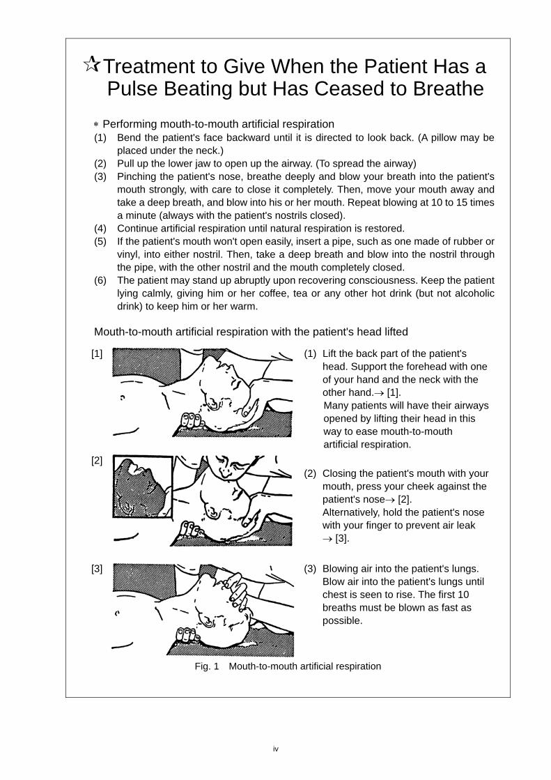
Treatment to Give When the Patient Has a Pulse Beating but Has Ceased to Breathe
Performing mouth-to-mouth artificial respiration (1) Bend the patient's face backward until it is directed to look back. (A pillow may be
placed under the neck.) (2) Pull up the lower jaw to open up the airway. (To spread the airway) (3) Pinching the patient's nose, breathe deeply and blow your breath into the patient's
mouth strongly, with care to close it completely. Then, move your mouth away and take a deep breath, and blow into his or her mouth. Repeat blowing at 10 to 15 times a minute (always with the patient's nostrils closed).
(4) Continue artificial respiration until natural respiration is restored. (5) If the patient's mouth won't open easily, insert a pipe, such as one made of rubber or
vinyl, into either nostril. Then, take a deep breath and blow into the nostril through the pipe, with the other nostril and the mouth completely closed.
(6) The patient may stand up abruptly upon recovering consciousness. Keep the patient lying calmly, giving him or her coffee, tea or any other hot drink (but not alcoholic drink) to keep him or her warm.
Mouth-to-mouth artificial respiration with the patient's head lifted
[1]
(1) Lift the back part of the patient's head. Support the forehead with one of your hand and the neck with the other hand. [1]. Many patients will have their airways opened by lifting their head in this way to ease mouth-to-mouth artificial respiration.
[2]
(2) Closing the patient's mouth with your
mouth, press your cheek against the patient's nose [2]. Alternatively, hold the patient's nose with your finger to prevent air leak [3].
[3]
(3) Blowing air into the patient's lungs. Blow air into the patient's lungs until chest is seen to rise. The first 10 breaths must be blown as fast as possible.
Fig. 1 Mouth-to-mouth artificial respiration
v
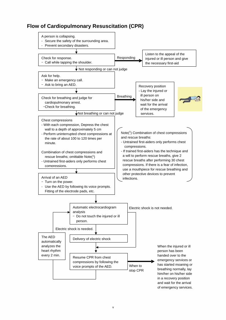
Flow of Cardiopulmonary Resuscitation (CPR)
A person is collapsing. - Secure the safety of the surrounding area. - Prevent secondary disasters.
Check for response. - Call while tapping the shoulder.
Breathing
Recovery position - Lay the injured or ill person on his/her side and wait for the arrival of the emergency services.
Not responding or can not judge
Ask for help. - Make an emergency call. - Ask to bring an AED.
Listen to the appeal of the injured or ill person and give the necessary first-aid
Responding
Not breathing or can not judge
Chest compressions - With each compression, Depress the chest
wall to a depth of approximately 5 cm - Perform uninterrupted chest compressions at
the rate of about 100 to 120 times per minute.
Combination of chest compressions and
rescue breaths; omittable Note(1) - Untrained first-aiders only performs chest
compressions.
Note(1) Combination of chest compressions and rescue breaths: - Untrained first-aiders only performs chest
compressions. - If trained first-aiders has the technique and a will to perform rescue breaths, give 2 rescue breaths after performing 30 chest compressions. If there is a fear of infection, use a mouthpiece for rescue breathing and other protective devices to prevent infections.
Check for breathing and judge for cardiopulmonary arrest.
- Check for breathing.
Arrival of an AED
- Turn on the power.
- Use the AED by following its voice prompts. Fitting of the electrode pads, etc.
Automatic electrocardiogram analysis - Do not touch the injured or ill
person.
Electric shock is needed.
Electric shock is not needed.
Delivery of electric shock
Resume CPR from chest compressions by following the voice prompts of the AED.
When the injured or ill person has been handed over to the emergency services or has started moaning or breathing normally, lay him/her on his/her side in a recovery position and wait for the arrival of emergency services.
When to stop CPR
A person is collapsing. - Secure the safety of the surrounding area. - Prevent secondary disasters.
The AED automatically analyzes the heart rhythm every 2 min.
vi
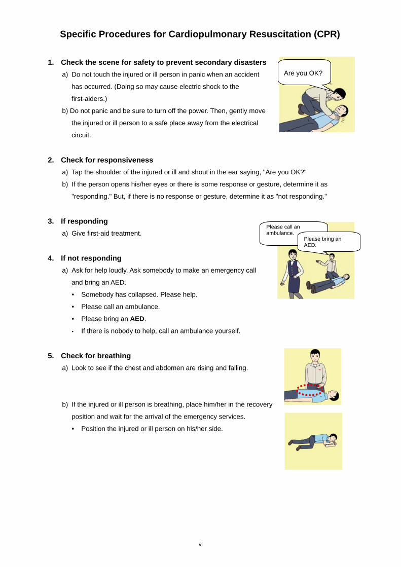
Specific Procedures for Cardiopulmonary Resuscitation (CPR)
1. Check the scene for safety to prevent secondary disasters
a) Do not touch the injured or ill person in panic when an accident
has occurred. (Doing so may cause electric shock to the
first-aiders.)
b) Do not panic and be sure to turn off the power. Then, gently move
the injured or ill person to a safe place away from the electrical
circuit.
2. Check for responsiveness
a) Tap the shoulder of the injured or ill and shout in the ear saying, "Are you OK?"
b) If the person opens his/her eyes or there is some response or gesture, determine it as
"responding." But, if there is no response or gesture, determine it as "not responding."
3. If responding
a) Give first-aid treatment.
4. If not responding
a) Ask for help loudly. Ask somebody to make an emergency call
and bring an AED.
• Somebody has collapsed. Please help.
• Please call an ambulance.
• Please bring an AED.
• If there is nobody to help, call an ambulance yourself.
5. Check for breathing
a) Look to see if the chest and abdomen are rising and falling.
b) If the injured or ill person is breathing, place him/her in the recovery
position and wait for the arrival of the emergency services.
• Position the injured or ill person on his/her side.
Are you OK?
Please call an ambulance.
Please bring an AED.
vii
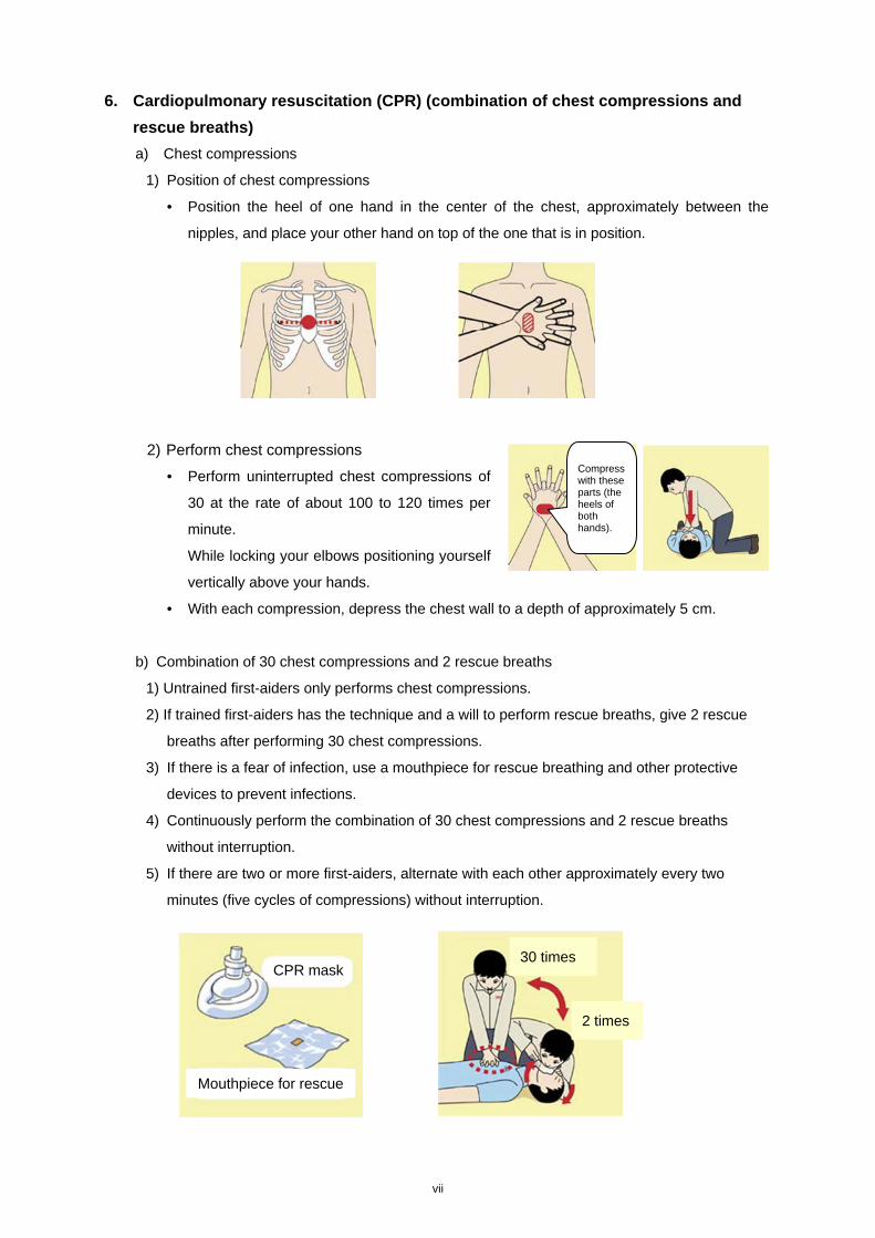
6. Cardiopulmonary resuscitation (CPR) (combination of chest compressions and
rescue breaths)
a) Chest compressions
1) Position of chest compressions
• Position the heel of one hand in the center of the chest, approximately between the
nipples, and place your other hand on top of the one that is in position.
2) Perform chest compressions
• Perform uninterrupted chest compressions of
30 at the rate of about 100 to 120 times per
minute.
While locking your elbows positioning yourself
vertically above your hands.
• With each compression, depress the chest wall to a depth of approximately 5 cm.
b) Combination of 30 chest compressions and 2 rescue breaths
1) Untrained first-aiders only performs chest compressions.
2) If trained first-aiders has the technique and a will to perform rescue breaths, give 2 rescue
breaths after performing 30 chest compressions.
3) If there is a fear of infection, use a mouthpiece for rescue breathing and other protective
devices to prevent infections.
4) Continuously perform the combination of 30 chest compressions and 2 rescue breaths
without interruption.
5) If there are two or more first-aiders, alternate with each other approximately every two
minutes (five cycles of compressions) without interruption.
30 times
Compress with these parts (the heels of both hands).
2 times
Mouthpiece for rescue
CPR mask
viii
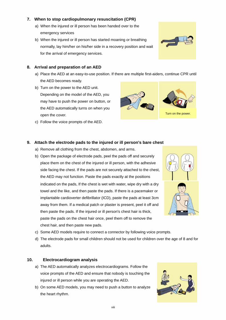
7. When to stop cardiopulmonary resuscitation (CPR)
a) When the injured or ill person has been handed over to the
emergency services
b) When the injured or ill person has started moaning or breathing
normally, lay him/her on his/her side in a recovery position and wait
for the arrival of emergency services.
8. Arrival and preparation of an AED
a) Place the AED at an easy-to-use position. If there are multiple first-aiders, continue CPR until
the AED becomes ready.
b) Turn on the power to the AED unit.
Depending on the model of the AED, you
may have to push the power on button, or
the AED automatically turns on when you
open the cover.
c) Follow the voice prompts of the AED.
9. Attach the electrode pads to the injured or ill person's bare chest
a) Remove all clothing from the chest, abdomen, and arms.
b) Open the package of electrode pads, peel the pads off and securely
place them on the chest of the injured or ill person, with the adhesive
side facing the chest. If the pads are not securely attached to the chest,
the AED may not function. Paste the pads exactly at the positions
indicated on the pads, If the chest is wet with water, wipe dry with a dry
towel and the like, and then paste the pads. If there is a pacemaker or
implantable cardioverter defibrillator (ICD), paste the pads at least 3cm
away from them. If a medical patch or plaster is present, peel it off and
then paste the pads. If the injured or ill person's chest hair is thick,
paste the pads on the chest hair once, peel them off to remove the
chest hair, and then paste new pads.
c) Some AED models require to connect a connector by following voice prompts.
d) The electrode pads for small children should not be used for children over the age of 8 and for
adults.
10. Electrocardiogram analysis
a) The AED automatically analyzes electrocardiograms. Follow the
voice prompts of the AED and ensure that nobody is touching the
injured or ill person while you are operating the AED.
b) On some AED models, you may need to push a button to analyze
the heart rhythm.
Turn on the power.
ix
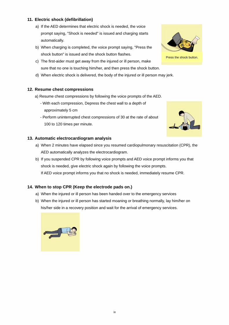
11. Electric shock (defibrillation)
a) If the AED determines that electric shock is needed, the voice
prompt saying, "Shock is needed" is issued and charging starts
automatically.
b) When charging is completed, the voice prompt saying, "Press the
shock button" is issued and the shock button flashes.
c) The first-aider must get away from the injured or ill person, make
sure that no one is touching him/her, and then press the shock button.
d) When electric shock is delivered, the body of the injured or ill person may jerk.
12. Resume chest compressions
a) Resume chest compressions by following the voice prompts of the AED.
- With each compression, Depress the chest wall to a depth of
approximately 5 cm
- Perform uninterrupted chest compressions of 30 at the rate of about
100 to 120 times per minute.
13. Automatic electrocardiogram analysis
a) When 2 minutes have elapsed since you resumed cardiopulmonary resuscitation (CPR), the
AED automatically analyzes the electrocardiogram.
b) If you suspended CPR by following voice prompts and AED voice prompt informs you that
shock is needed, give electric shock again by following the voice prompts.
If AED voice prompt informs you that no shock is needed, immediately resume CPR.
14. When to stop CPR (Keep the electrode pads on.)
a) When the injured or ill person has been handed over to the emergency services
b) When the injured or ill person has started moaning or breathing normally, lay him/her on
his/her side in a recovery position and wait for the arrival of emergency services.
Press the shock button.
x
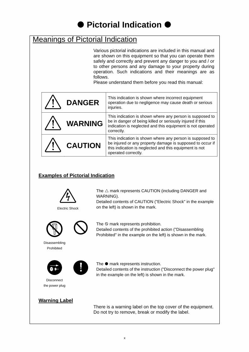
Pictorial Indication
Meanings of Pictorial Indication Various pictorial indications are included in this manual and are shown on this equipment so that you can operate them safely and correctly and prevent any danger to you and / or to other persons and any damage to your property during operation. Such indications and their meanings are as follows. Please understand them before you read this manual:
DANGER This indication is shown where incorrect equipment operation due to negligence may cause death or serious injuries.
WARNING This indication is shown where any person is supposed to be in danger of being killed or seriously injured if this indication is neglected and this equipment is not operated correctly.
CAUTION This indication is shown where any person is supposed to be injured or any property damage is supposed to occur if this indication is neglected and this equipment is not operated correctly.
Examples of Pictorial Indication
Electric Shock
The mark represents CAUTION (including DANGER and WARNING). Detailed contents of CAUTION ("Electric Shock" in the example on the left) is shown in the mark.
Disassembling
Prohibited
The mark represents prohibition. Detailed contents of the prohibited action ("Disassembling Prohibited" in the example on the left) is shown in the mark.
Disconnect
the power plug
The mark represents instruction. Detailed contents of the instruction ("Disconnect the power plug" in the example on the left) is shown in the mark.
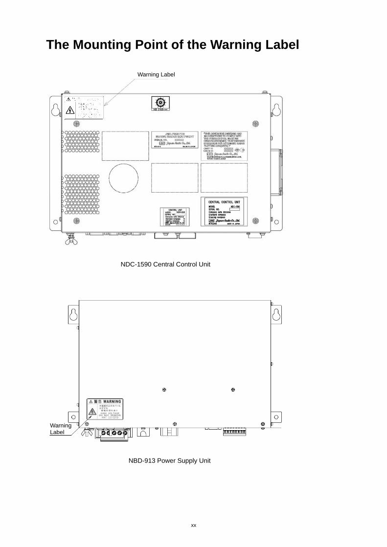
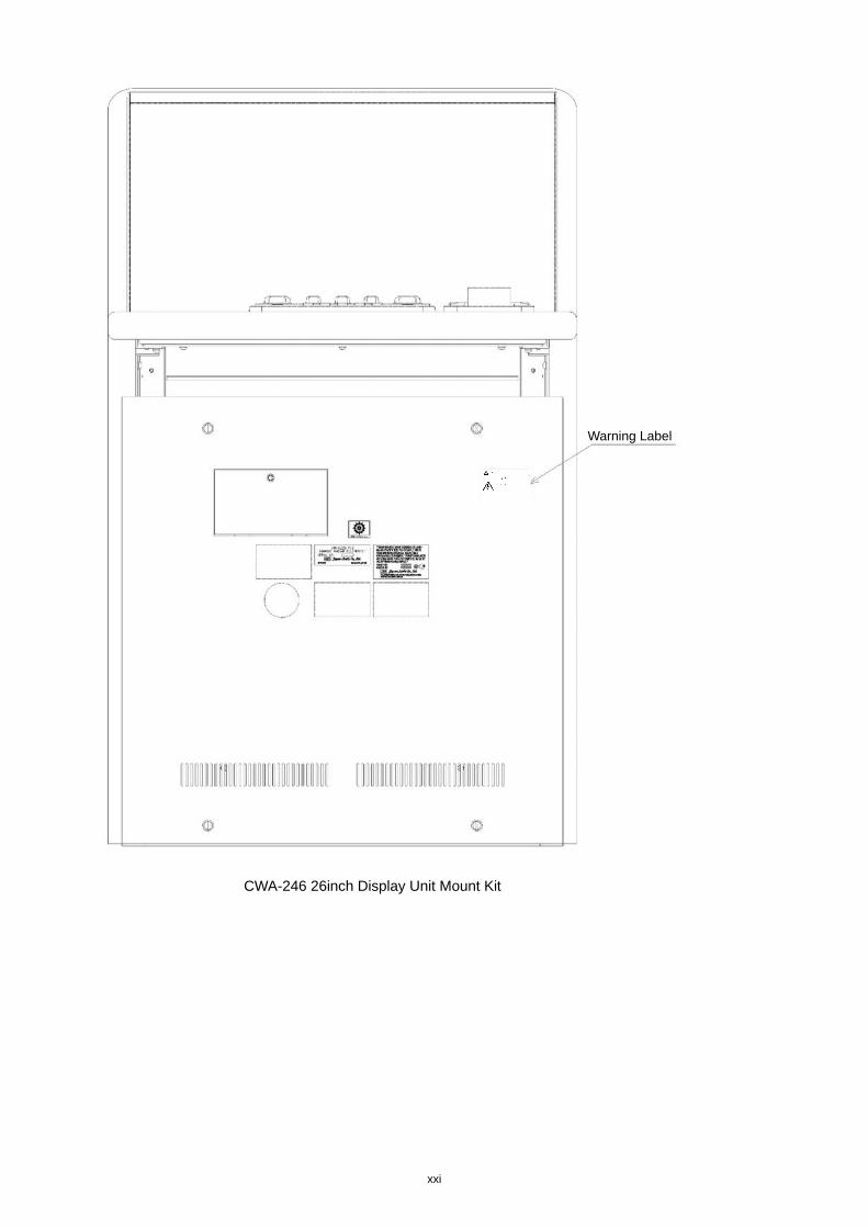
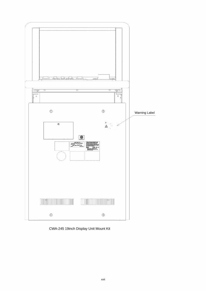
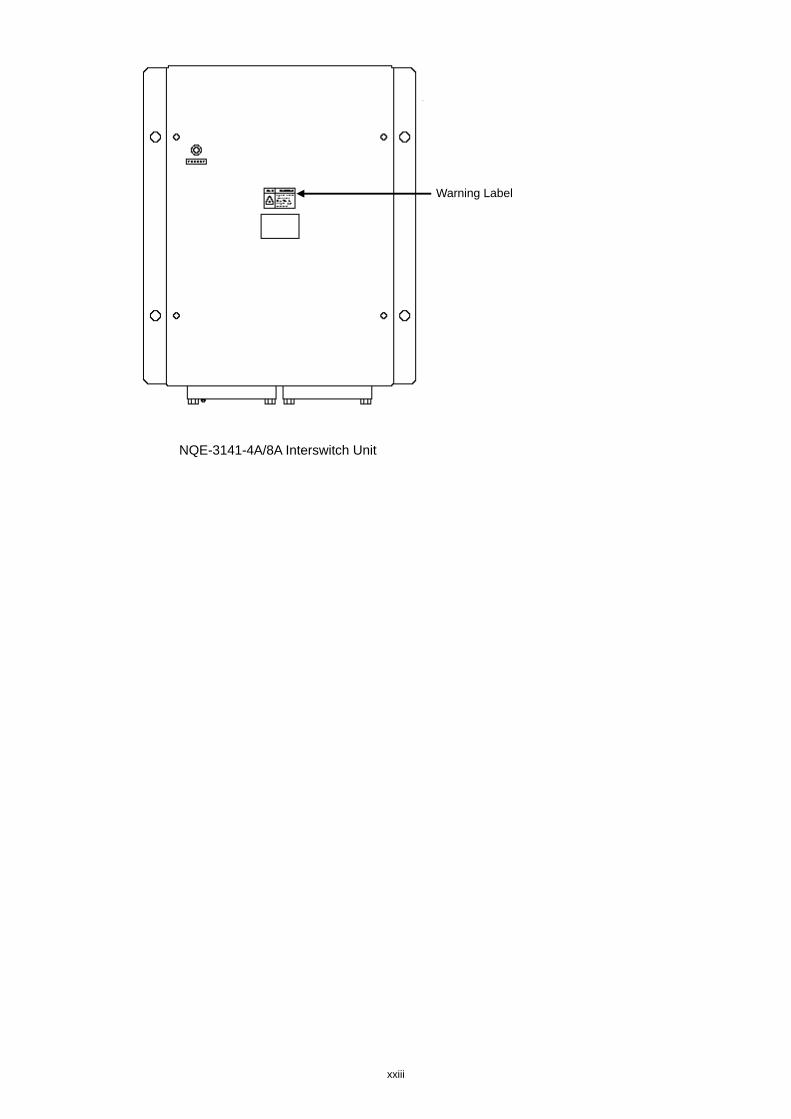
Warning Label There is a warning label on the top cover of the equipment. Do not try to remove, break or modify the label.
xi
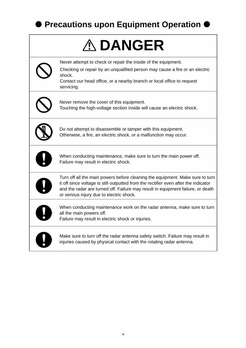
Precautions upon Equipment Operation
DANGER
Never attempt to check or repair the inside of the equipment.
Checking or repair by an unqualified person may cause a fire or an electric shock. Contact our head office, or a nearby branch or local office to request servicing.
Never remove the cover of this equipment. Touching the high-voltage section inside will cause an electric shock.
Do not attempt to disassemble or tamper with this equipment. Otherwise, a fire, an electric shock, or a malfunction may occur.
When conducting maintenance, make sure to turn the main power off. Failure may result in electric shock.
Turn off all the main powers before cleaning the equipment. Make sure to turn it off since voltage is still outputted from the rectifier even after the indicator and the radar are turned off. Failure may result in equipment failure, or death or serious injury due to electric shock.
When conducting maintenance work on the radar antenna, make sure to turn all the main powers off. Failure may result in electric shock or injuries.
Make sure to turn off the radar antenna safety switch. Failure may result in injuries caused by physical contact with the rotating radar antenna.
xii
When turning off the power supply, do not hold down the power button of the operation unit. Otherwise, a trouble may occur due to termination failure.
Never directly touch the internal components of the radar antenna or indicator. Direct contact with these high-voltage components may cause electric shock. For maintenance, inspection, or adjustment of equipment components, consult with our branch office, branch shop, sales office, or our distributor in your district.
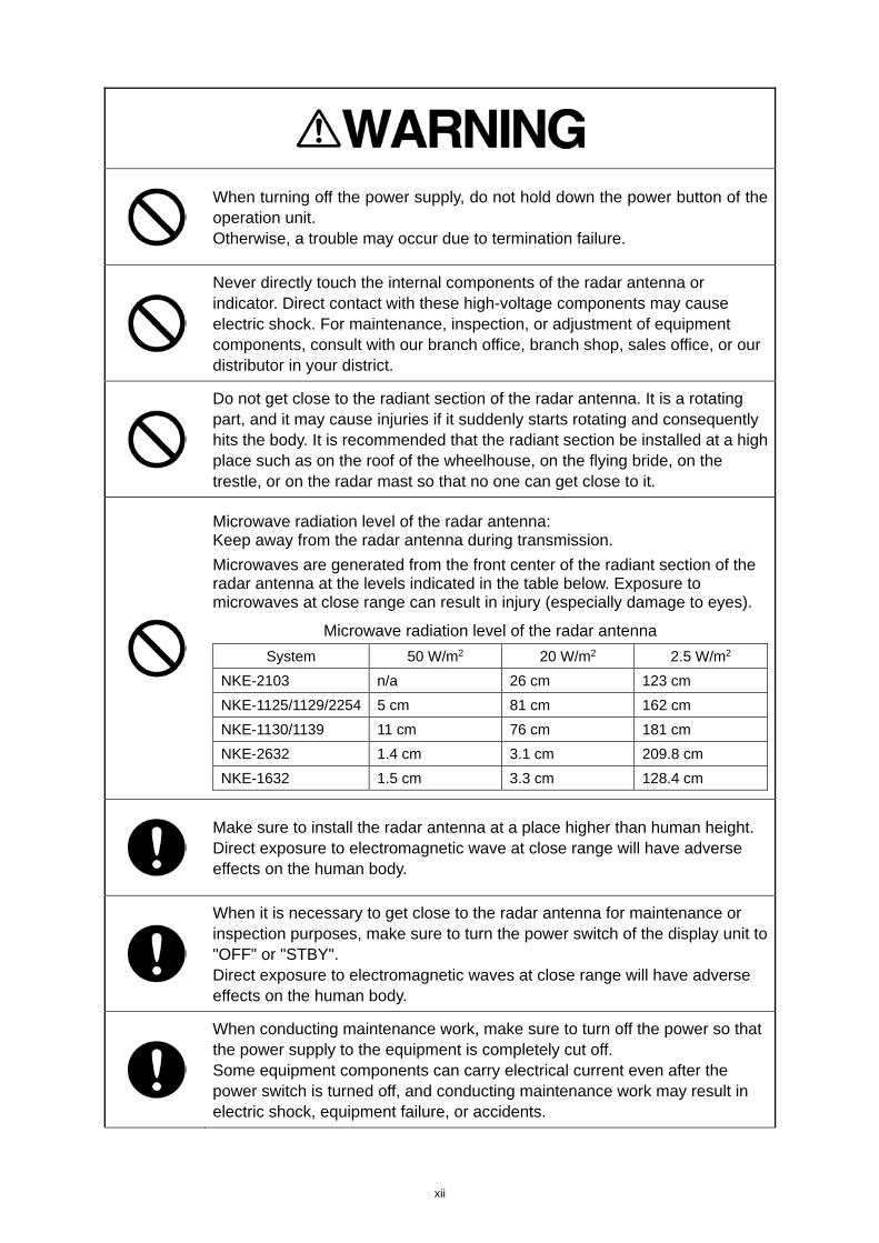
Do not get close to the radiant section of the radar antenna. It is a rotating part, and it may cause injuries if it suddenly starts rotating and consequently hits the body. It is recommended that the radiant section be installed at a high place such as on the roof of the wheelhouse, on the flying bride, on the trestle, or on the radar mast so that no one can get close to it.
Microwave radiation level of the radar antenna: Keep away from the radar antenna during transmission.
Microwaves are generated from the front center of the radiant section of the radar antenna at the levels indicated in the table below. Exposure to microwaves at close range can result in injury (especially damage to eyes).
Microwave radiation level of the radar antenna
System 50 W/m2 20 W/m2 2.5 W/m2
NKE-2103 n/a 26 cm 123 cm
NKE-1125/1129/2254 5 cm 81 cm 162 cm
NKE-1130/1139 11 cm 76 cm 181 cm
NKE-2632 1.4 cm 3.1 cm 209.8 cm
NKE-1632 1.5 cm 3.3 cm 128.4 cm
Make sure to install the radar antenna at a place higher than human height. Direct exposure to electromagnetic wave at close range will have adverse effects on the human body.
When it is necessary to get close to the radar antenna for maintenance or inspection purposes, make sure to turn the power switch of the display unit to "OFF" or "STBY". Direct exposure to electromagnetic waves at close range will have adverse effects on the human body.
When conducting maintenance work, make sure to turn off the power so that the power supply to the equipment is completely cut off. Some equipment components can carry electrical current even after the power switch is turned off, and conducting maintenance work may result in electric shock, equipment failure, or accidents.
xiii
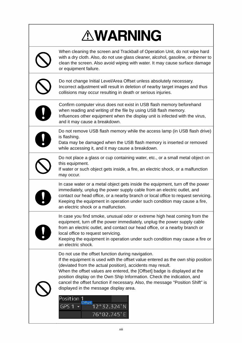
When cleaning the screen and Trackball of Operation Unit, do not wipe hard with a dry cloth. Also, do not use glass cleaner, alcohol, gasoline, or thinner to clean the screen. Also avoid wiping with water. It may cause surface damage or equipment failure.
Do not change Initial Level/Area Offset unless absolutely necessary. Incorrect adjustment will result in deletion of nearby target images and thus collisions may occur resulting in death or serious injuries.
Confirm computer virus does not exist in USB flash memory beforehand when reading and writing of the file by using USB flash memory. Influences other equipment when the display unit is infected with the virus, and it may cause a breakdown.
Do not remove USB flash memory while the access lamp (in USB flash drive) is flashing. Data may be damaged when the USB flash memory is inserted or removed while accessing it, and it may cause a breakdown.
Do not place a glass or cup containing water, etc., or a small metal object on this equipment. If water or such object gets inside, a fire, an electric shock, or a malfunction may occur.
In case water or a metal object gets inside the equipment, turn off the power immediately, unplug the power supply cable from an electric outlet, and contact our head office, or a nearby branch or local office to request servicing. Keeping the equipment in operation under such condition may cause a fire, an electric shock or a malfunction.
In case you find smoke, unusual odor or extreme high heat coming from the equipment, turn off the power immediately, unplug the power supply cable from an electric outlet, and contact our head office, or a nearby branch or local office to request servicing. Keeping the equipment in operation under such condition may cause a fire or an electric shock.
Do not use the offset function during navigation. If the equipment is used with the offset value entered as the own ship position (deviated from the actual position), accidents may result. When the offset values are entered, the [Offset] badge is displayed at the position display on the Own Ship Information. Check the indication, and cancel the offset function if necessary. Also, the message "Position Shift" is displayed in the message display area.
xiv
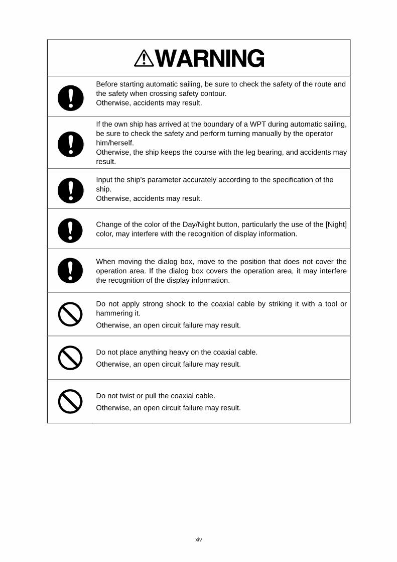
Before starting automatic sailing, be sure to check the safety of the route and the safety when crossing safety contour. Otherwise, accidents may result.
If the own ship has arrived at the boundary of a WPT during automatic sailing, be sure to check the safety and perform turning manually by the operator him/herself. Otherwise, the ship keeps the course with the leg bearing, and accidents may result.
Input the ship’s parameter accurately according to the specification of the ship. Otherwise, accidents may result.
Change of the color of the Day/Night button, particularly the use of the [Night] color, may interfere with the recognition of display information.
When moving the dialog box, move to the position that does not cover the operation area. If the dialog box covers the operation area, it may interfere the recognition of the display information.
Do not apply strong shock to the coaxial cable by striking it with a tool or hammering it.
Otherwise, an open circuit failure may result.
Do not place anything heavy on the coaxial cable.
Otherwise, an open circuit failure may result.
Do not twist or pull the coaxial cable.
Otherwise, an open circuit failure may result.
xv
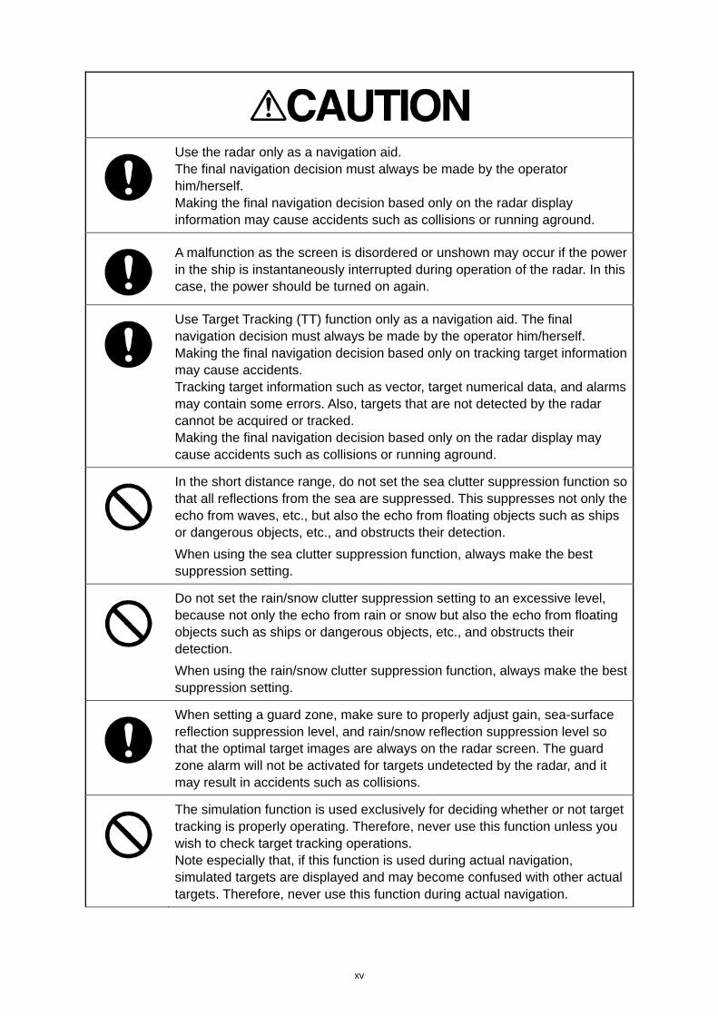
Use the radar only as a navigation aid. The final navigation decision must always be made by the operator him/herself. Making the final navigation decision based only on the radar display information may cause accidents such as collisions or running aground.
A malfunction as the screen is disordered or unshown may occur if the power in the ship is instantaneously interrupted during operation of the radar. In this case, the power should be turned on again.
Use Target Tracking (TT) function only as a navigation aid. The final navigation decision must always be made by the operator him/herself. Making the final navigation decision based only on tracking target information may cause accidents. Tracking target information such as vector, target numerical data, and alarms may contain some errors. Also, targets that are not detected by the radar cannot be acquired or tracked. Making the final navigation decision based only on the radar display may cause accidents such as collisions or running aground.
In the short distance range, do not set the sea clutter suppression function so that all reflections from the sea are suppressed. This suppresses not only the echo from waves, etc., but also the echo from floating objects such as ships or dangerous objects, etc., and obstructs their detection.
When using the sea clutter suppression function, always make the best suppression setting.
Do not set the rain/snow clutter suppression setting to an excessive level, because not only the echo from rain or snow but also the echo from floating objects such as ships or dangerous objects, etc., and obstructs their detection.
When using the rain/snow clutter suppression function, always make the best suppression setting.
When setting a guard zone, make sure to properly adjust gain, sea-surface reflection suppression level, and rain/snow reflection suppression level so that the optimal target images are always on the radar screen. The guard zone alarm will not be activated for targets undetected by the radar, and it may result in accidents such as collisions.
The simulation function is used exclusively for deciding whether or not target tracking is properly operating. Therefore, never use this function unless you wish to check target tracking operations. Note especially that, if this function is used during actual navigation, simulated targets are displayed and may become confused with other actual targets. Therefore, never use this function during actual navigation.
xvi
Since these alarms may include some errors depending on the target tracking conditions, the navigation officer himself should make the final decision for ship operations such as collision avoidance.
Making the final navigation decision based only on the alarm may cause
accidents such as collisions.
Optimal values have been set for VD Level and Constant; therefore, never change their values unless absolutely necessary. Failure may result in accidents that would lower target tracking performance.
When replacing magnetrons, make sure to shut off the main power and let the equipment stand for more than 5 minutes to discharge the high-voltage circuit. Failure may result in electric shock.
Make sure to take off your watch when your hand must get close to the magnetron. Failure may result in damage to the watch since the magnetron is a strong magnet.
Make sure that two or more staff member work together when replacing the LCD. If only one person attempts to replace the LCD, he/she may drop it and become injured.
Any adjustments must be made by specialized service personnel.
Incorrect settings may result in unstable operation, and this may lead to accidents or equipment failure.
Do not make any adjustments during navigation. Failure may result in adverse effects on the radar function which may lead to accidents or equipment failure.
Do not change the quantization level settings unless absolutely necessary. If set at an inappropriate value, the acquisition of target tracking function and the tracking function deteriorate, and this may lead to accidents.
Do not use or leave the equipment under direct sunlight for a long time or in the temperatures above 55°C. Otherwise, a fire or a malfunction may occur.
xvii
Do not block the ventilation opening of the equipment. Otherwise, heat may accumulate inside to cause a fire or a malfunction.
This equipment is intended for use as an aid to navigation only. • If no backup measures, such as using another ECDIS unit for
confirmation, are taken, be sure to use official marine charts together with this equipment to make any navigational decision.
• This equipment is not designed to assess the positional information automatically. The positional information should always be checked by the operator. Otherwise, accidents may result.
Do not touch the equipment with hands or gloves wet with water. Otherwise, an electric shock or a malfunction may occur.
Do not leave the disc in the DVD drive. Malfunctions of the drives may result.
• Do not place any object on the operation panel.
In particular, if a hot object is placed on the operation panel, it can cause
deformation of the surface of the operation panel. • Do not apply any undue shock on the operation panel, trackball and dials.
Otherwise, a malfunction may result.
Make sure that the main power is turned off before inspection or replacement
of parts.
Otherwise, an electric shock, a fire, or a malfunction may occur.
• If a fan alarm or CPU temperature rise alarm has occurred, immediately turn off the power. Keeping the equipment in operation under such condition may cause a fire or a malfunction. After turning off the power, contact our head office, or a nearby branch or local office to request servicing.
Edit routes in accordance with the world geodetic system (WGS-84). Use of routes edited with any other geodetic systems may cause accidents.
xviii
During sailing, be sure to check the own ship’s position and bearing as often as necessary, regardless of whether the automatic sailing is in operation or not. Otherwise, accidents may result.
Do not turn off the power during Backup/Restore. Otherwise, a function may fail, and an accident may occur.
Do not do the backup operation of data while sailing. The radar application should be ended to begin the data backup. It becomes impossible to observe using radar and this may lead to accidents.
The backup power supply (DC power supply, etc.) of the equipment must be connected when recovery of the C drive image is performed. If the power supply stops during recovery, an equipment activation fault occurs, causing an accident.
Do not turn off the power supply during recovery of C drive image.
Otherwise, a function fault occurs, causing an accident.
Since the image within the previous observation range is displayed by expanding/contracting for the period from immediately after switching of the observation range from the next image updating, do not use this image for navigation.
If this image is used for navigation, an accident may occur.
In the case of turning on the power under the condition of low temperature, do pre-heat more than 30 minutes. Otherwise, an operation failure may occur and an accident may occur.
Normally, use the automatic tuning mode.
If you use the manual tuning mode, an accident may be caused by a transmission/reception problem.
Use the manual tuning mode only when you cannot bet the best tuning conditions in the automatic tuning mode.
Always keep the sensitivity adjusted to the best condition.
If you raise the sensitivity excessively, the visibility of the target will be reduced by unwanted signals including receiver noise and pseudo image. This may cause an accident.
If the sensitivity is reduced excessively, detection of a target such as a ship or hazardous material will be interrupted.
xix
Adjust the preset of the observation scene according to the oceanographic
condition, with the thorough understanding of the features of the radar signal
processing setting. The optimum radar performance may not be able to be
demonstrated due to the contents of the changed setting or the
oceanographic condition at that time.
Never changes or modifications the equipment by user with not expressly
approved method. Otherwise, the party responsible for compliance could void
the user’s authority to operate the equipment.
This equipment has been tested and found to comply with the limits for a
Class A digital device, pursuant to part 15 of the FCC Rules. These limits are
designed to provide reasonable protection against harmful interference when
the equipment is operated in a commercial environment. This equipment
generates, uses, and can radiate radio frequency energy and, if not installed
and used in accordance with the instruction manual, may cause harmful
interference to radio communications. Operation of this equipment in a
residential area is likely to cause harmful interference in which case the user
will be required to correct the interference at his own expense.
xx
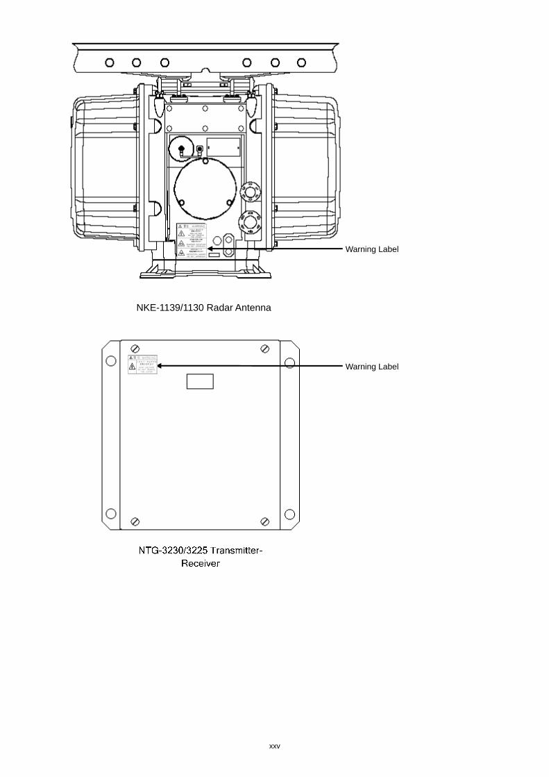
The Mounting Point of the Warning Label
NDC-1590 Central Control Unit
NBD-913 Power Supply Unit
Warning Label
Warning Label
xxi
CWA-246 26inch Display Unit Mount Kit
Warning Label
xxii
CWA-245 19inch Display Unit Mount Kit
Warning Label
xxiii
NQE-3141-4A/8A Interswitch Unit
Warning Label
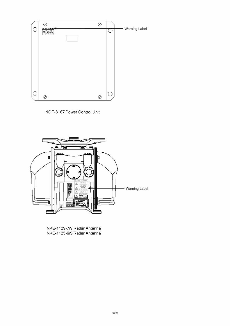
xxiv
Warning Label
Warning Label
xxv
Warning Label
Warning Label
NKE-1139/1130 Radar Antenna
xxvi
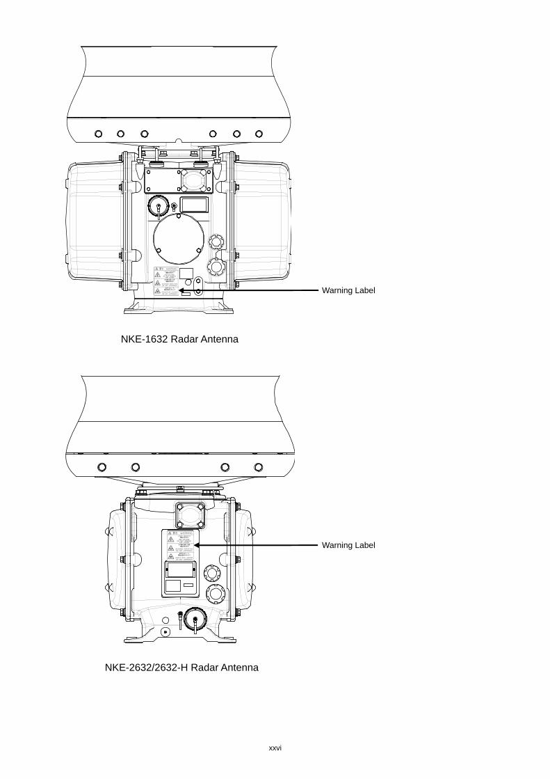
Warning Label
NKE-1632 Radar Antenna
Warning Label
NKE-2632/2632-H Radar Antenna
xxvii
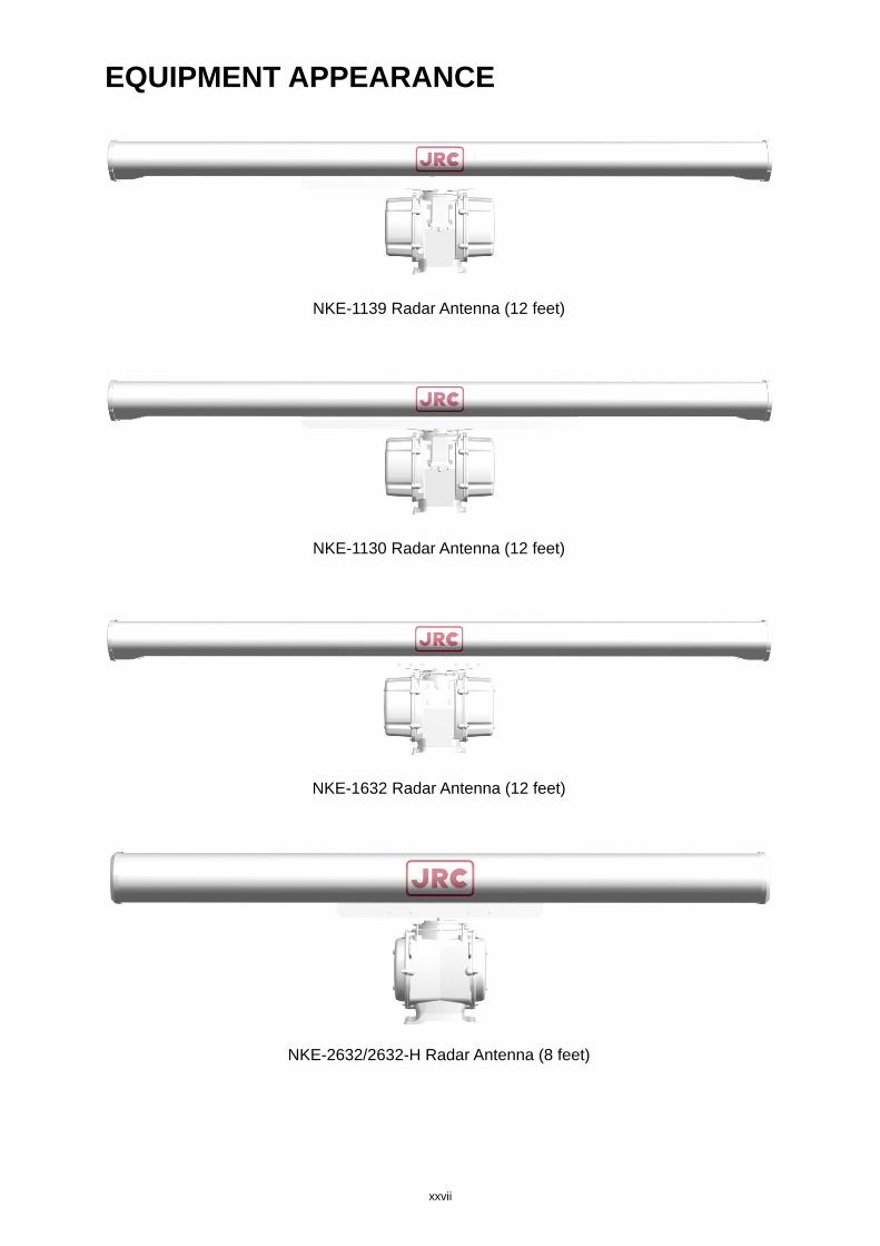
EQUIPMENT APPEARANCE
NKE-1139 Radar Antenna (12 feet)
NKE-1130 Radar Antenna (12 feet)
NKE-1632 Radar Antenna (12 feet)
NKE-2632/2632-H Radar Antenna (8 feet)

xxviii
NTG-3230 Transmitter-Receiver (30 kW)
xxix
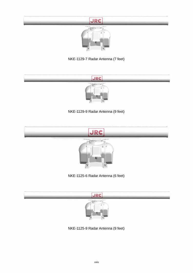
NKE-1129-7 Radar Antenna (7 feet)
NKE-1129-9 Radar Antenna (9 feet)
NKE-1125-6 Radar Antenna (6 feet)
NKE-1125-9 Radar Antenna (9 feet)
xxx
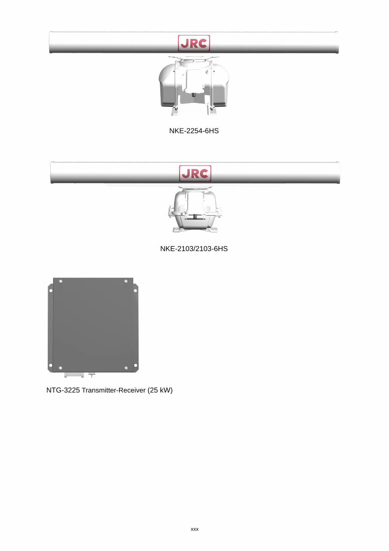
NKE-2254-6HS
NKE-2103/2103-6HS
NTG-3225 Transmitter-Receiver (25 kW)
xxxi
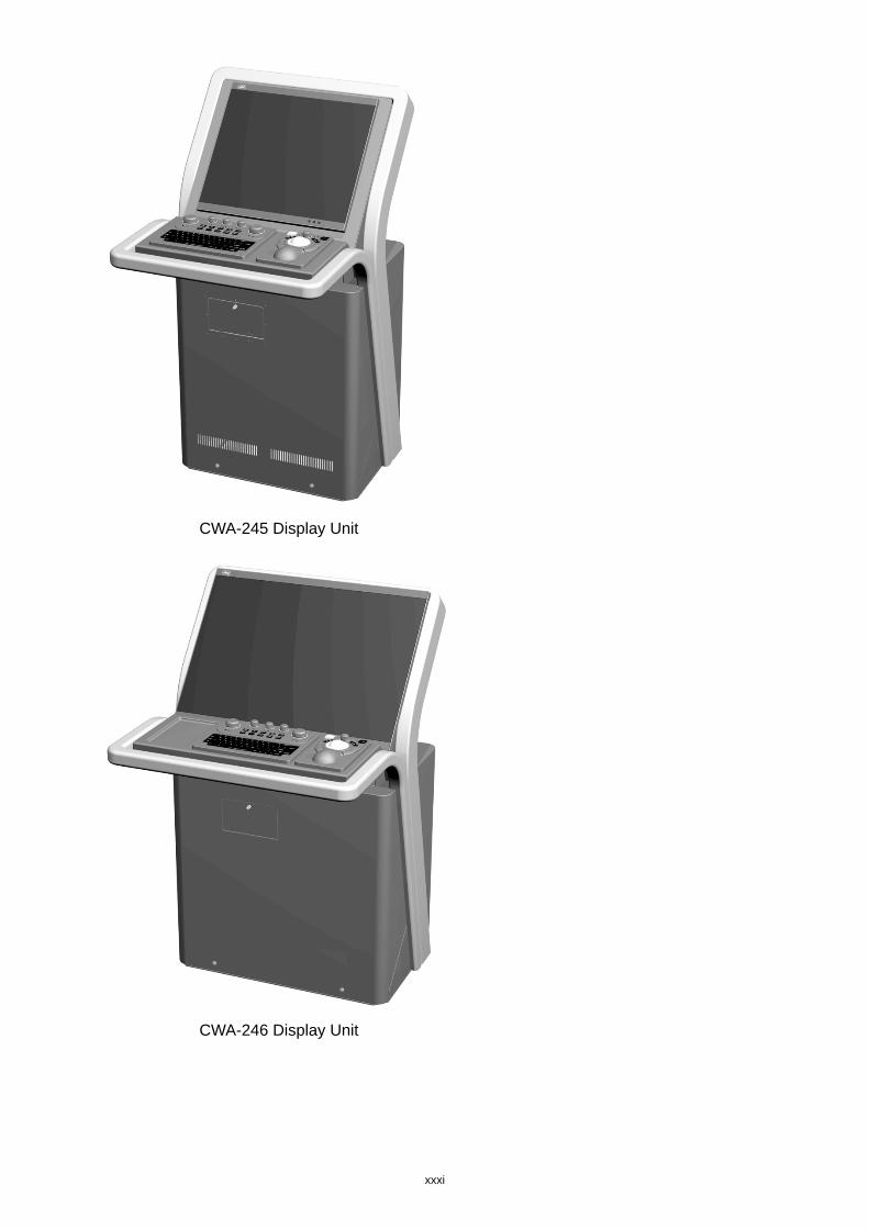
CWA-245 Display Unit
CWA-246 Display Unit
xxxii
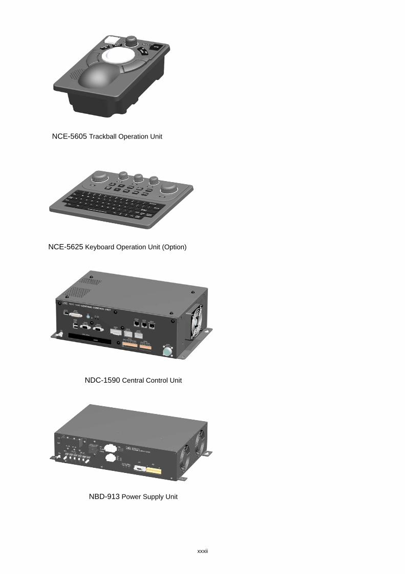
NCE-5605 Trackball Operation Unit
NCE-5625 Keyboard Operation Unit (Option)
NDC-1590 Central Control Unit
NBD-913 Power Supply Unit
xxxiii
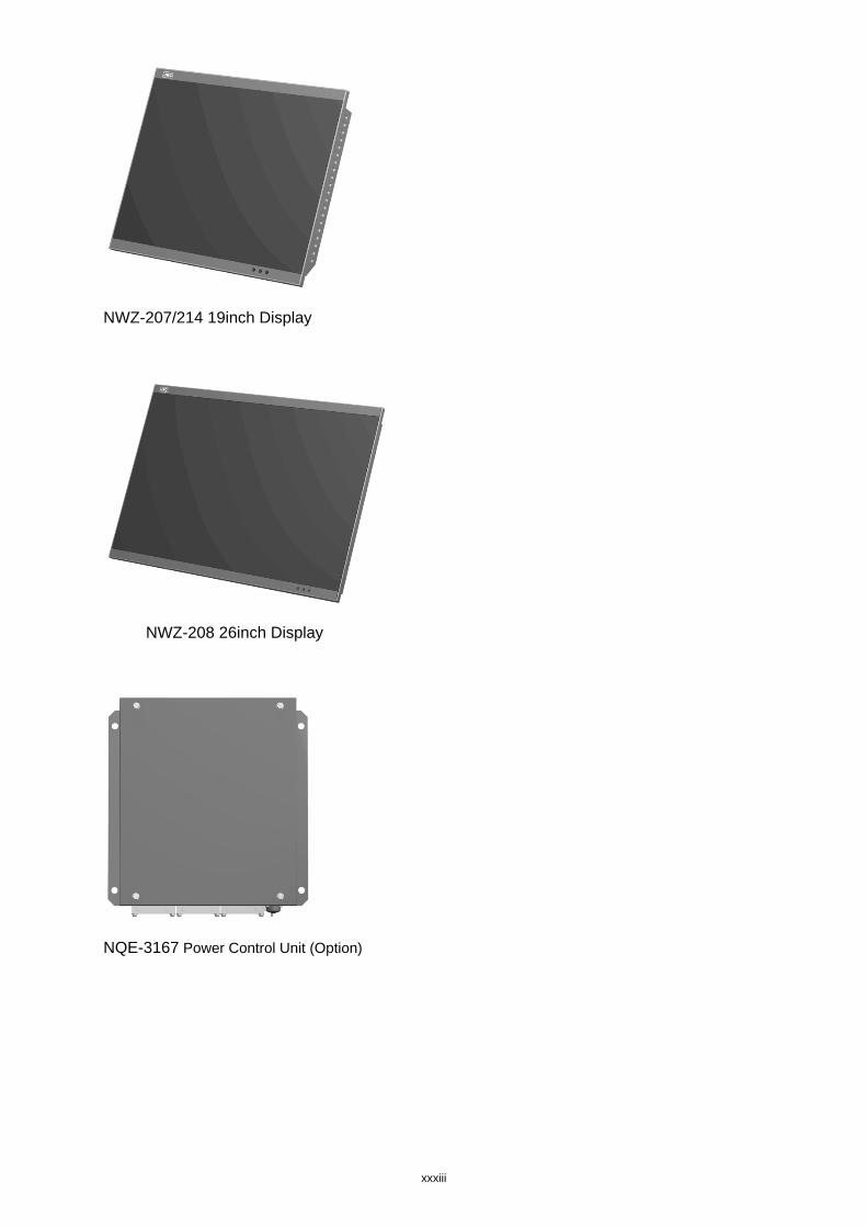
NWZ-207/214 19inch Display
NWZ-208 26inch Display
NQE-3167 Power Control Unit (Option)
xxxiv
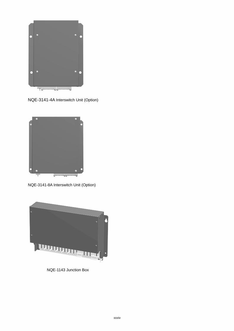
NQE-3141-4A Interswitch Unit (Option)
NQE-3141-8A Interswitch Unit (Option)
NQE-1143 Junction Box
Glossary
AIO : Admiralty Information Overlay published by United Kingdom
Hydrographic Office (UKHO).
AIS : Automatic Identification System
ARCS : Admiralty Raster Chart Service. A raster chart published by UKHO
Autosail : The system automatically navigates to keep the scheduled route.
Same as automatic sailing.
AZ : Acquisition/Activation zone
Anti-clutter rain : Rain/snow clutter suppression
Anti-clutter sea : Sea clutter suppression
AZI : AZImuth stabilization mode
Base CD : Chart CD containing a complete chart data
BCR/BCT : Bow Crossing Range/Bow Crossing Time
Cell Permit : A file containing an encryption key for S-63 chart. Supplied by UKHO,
PRIMAR STAVANGER, and Hydrographic and Oceanographic
Department of Japan Coast Guard.
Chart Maintenance : Software to manage the charts. Imports and updates the charts.
C-MAP Ed.3 : C-MAP Edition 3. A digital chart format by Jeppesen (formerly, C-MAP,
Norway)
C-MAP : Digital chart data by Jeppesen (formerly, C-MAP, Norway)
CTS : Course To Steer. Heading command.
COG : Course Over the Ground
C UP : Course up. Own ship’s course is pointed to the top center of the radar
display.
CCRP : Consistent Common Reference Point. The own ship position, to which
all horizontal measurements such as target range, bearing, relative
course, relative speed, CPA or TCPA are referenced, typically the
conning position of the bridge.
CORREL : CORRELation
xxxvi
CPA/TCPA : Distance to the Closest Point of Approach/Time to the Closest Point of
Approach.
CTW : Course Through Water. The direction of the ship's movement through
the water
Data Server : Organization providing S-63 chart
DIST : Distance
DR : Dead Reckoning
Dynamic License : Dynamic licensing of C-Map chart license by Jeppesen
DNV : Det Norske Veritas
DRIFT : The current velocity for manual correction or the current speed on the
horizontal axis of the 2-axis log is displayed.
EBL : Electronic Bearing Line
ECDIS : Electronic Chart Display and Information System
ENC : Electronic Navigation Chart. Meaning S-57 and S-63.
ETA : Estimated Time of Arrival
ETD : Estimated Time of Departure
ENH : Enhance
F.ETA : Final Estimated Time of Arrival. Estimated time of arrival to the last
WPT
GC : Great Circle
GPS : Global Positioning System
HDG : Heading. Ship’s heading
HL : Heading Line
HSC : High Speed Craft. Vessels which comply with the definition in SOLAS
for high speed craft
H UP : Head up. Own ship’s heading line is always pointed to the top center
of the radar display.
IHO : International Hydrographic Office
IMO : International Maritime Organization
IR : Radar Interference Rejecter
xxxvii
ISW : InterSWitch unit
LMT : Local Mean Time
LON : Longitude
LAT : Latitude
LP : Long Pulse
MED : Marine Equipment Directive. Request standard for standardization of
marine equipment within the EU region
MFD : Abbreviation of this equipment name. The formal name is Multi
Function Display. The navigation support functions such as radar,
ECDIS, CID, and AMS with this equipment can be executed by
switching.
MMSI : Maritime Mobile Service Identity
MOB : Man Over Board
MON : Performance MOnitor
MP : Medium Pulse
NM : Nautical Mile 1 nm=1852 m
N UP : The north is always pointed to the top center of the radar display.
(North up)
P0N : Unmodulated pulse, which is a type of transmission radio wave. While
it is a type of radio wave usually used by radars equipped with
magnetrons, radio waves with a short pulse length are used also by
solid-state radars for short-range detection.
PRIMAR STAVENGER : A Norwegian company supplying charts. Publisher of encrypted charts,
S-63
PI : Parallel Index line
Past positions : Equally time-spaced past position marks of a tracked or AIS target and
the own ship.
POSN : POSitioN
PRF : Pulse Repetition Frequency. The number of radar pulses transmitted
each second.
PROC : PROCess. Radar signal processing function
Q0N : A type of radio wave with intra-pulse frequency modulation. It is used
for solid-state pulse compression radars.
xxxviii
RL : Rhumb Line
RR : Range Rings
Relative vector : A predicted movement of a target relative to own ship’s motion
RM : Relative Motion. A display on which the position of own ship remains
fixed, and all targets move relative to own ship.
RM(R) : Relative Motion. Relative Trails
RM(T) : Relative Motion. True Trails
ROT : Rate Of Turn. Change of heading per time unit
Route : A set of waypoints
S-57 : IHO Transfer Standard for Digital Hydrographic Data
S-63 : IHO Data Protection Scheme
SA Certificate file : An electronic file certifying the supplier of S-63 chart. Required for
import/ update of S-63 chart.
SENC : System Electronic Navigational Chart
SOG : Speed Over the Ground
SART : Search And Rescue Transponder
SET : The current direction for manual correction or the current speed on the
horizontal axis of the 2-axis log is displayed.
SP : Short Pulse
STAB : STABilization
STW : Speed Through Water
TCS : Track Control Systems
TCPA : Time to Closest Point of Approach to own ship
TM : True Motion. A display across which the own ship and targets move
with their own true motions.
To WPT : To Waypoint (To WPT)
Trails : Tracks displayed by the radar echoes of targets in the form of an
afterglow
Trial maneuver : A graphical simulation facility used to assist the operator to perform a
proposed maneuver for navigation and collision avoidance purposes
xxxix
True vector : A vector representing the predicted true motion of a target, as a result
of input of the course and speed of the own ship
TT : Target Tracking
TTG : Time To Go. Time to next waypoint.
TXRX : Transmitter-Receiver Unit
UKHO : United Kingdom Hydrographic Office
Update CD : Chart CD containing the chart data updated from Base CD. This can
be used when Base CD data has been imported.
USER CODE : A user-specific code assigned by JRC. Required in using ARCS and
S-63 charts.
UTC : Universal Time, Coordinated
VRM : Variable Range Marker
VDR : Voyage Data Recorder
WOL : Wheel Over Line
WOP : Wheel Over Point
WPT : Waypoint
WPT-WPT : The division of the leg specified by two points. Displays data between
two consecutive waypoints.
XTD : Cross Track Distance
XTL : Cross Track Limit
Activated target : A target representing the automatic or manual activation of a sleeping
AIS target for the display of additional information
Associated target : A target simultaneously representing a tracked target and a AIS target
which are decided as the same
Chirp : A type of transmission waveform with intra-pulse frequency
modulation used by solid-state radars. Its radio wave type is classified
as Q0N.
Clutter : Unwanted reflections on a radar screen, from sea surface, rain or
snow.
Display : Screen displayed on the LCD
xl
Frequency deviation range : The range of variation of the Q0N frequency used for transmission
waves of a solid-state radar. Generally, the greater the frequency
deviation range, the higher the resolution in the range direction.
Hydrographic and Oceanographic Department :
Hydrographic and Oceanographic Department of Japan Coast Guard. Publisher of ENC
Import (Chart Maintenance) : A procedure of enabling the chart supplied by Base CD to be
displayed on ECDIS
Interswitch Unit : A device to switch over two or more radar display units and two or
more radar antennas
Leg : Line between two consecutive waypoints
Lost AIS target : A target symbol representing the last valid position of an AIS target
before the reception of its data was lost, or its last dead-reckoned
position.
Lost tracked target : One for which target information is no longer available due to poor, lost
or obscured signals.
Power amplifier : A radio frequency amplifier circuit consisting of semiconductor
elements used for solid-state radars. It employs a high frequency, high
power FET.
Primary : Main positioning sensor
Pulse compression : Correlation processing performed when a transmitted chirp signal is
received by a solid-state radar after reflecting off the target. This
processing gain enables the radar to have necessary detection
capability even when a transmission power is low.
Radar beacon : A navigation aid which responds to the radar transmission and
generates radio wave
Range : An area of the chart displayed on the screen. Represented by one half
of the length of the chart display screen.
Range side lobe : False image that is generated as a result of pulse compression
processing in the solid-state radar when there is a large target such as
a large ship in the vicinity.
Reference target : A fixed target specified to calculate the speed over the ground
Report : User report to be issued periodically for using the Dynamic License
method of Jeppesen continuously
Rubber band : Border that indicates the selected range.
Scale : The display scale
xli
Sea state : The average height of the wave expressed by dividing into several
classes.
Ship-avoiding operation : To operate the ship in order to avoid obstacles during automatic
navigation, regardless of the scheduled route
Sleeping AIS target : A target indicating the presence and orientation of a vessel equipped
with AIS
Spot depth : Numeric representation of depth
SSR: Solid State Radar : Radar that uses semiconductor elements instead of magnetron, which
requires periodic replacement. It is built with a system that ensures
necessary detection capability even when a transmission output is low,
by using chirp signals with a long pulse length upon transmission and
performing pulse compression upon reception
Update (Chart Maintenance) : A procedure of reflecting the update data supplied by Update CD on
the imported chart.
xlii
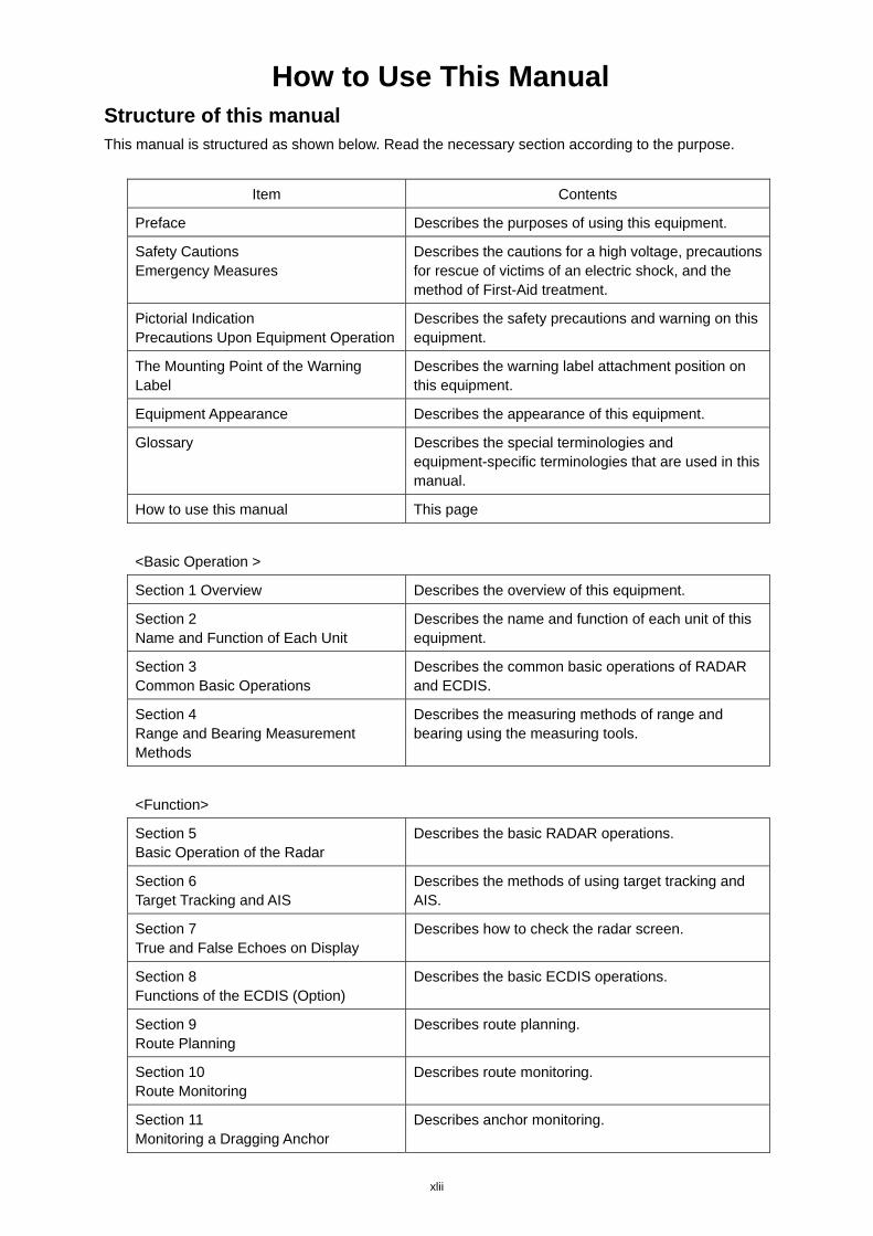
How to Use This Manual Structure of this manual This manual is structured as shown below. Read the necessary section according to the purpose.
Item Contents
Preface Describes the purposes of using this equipment.
Safety Cautions Emergency Measures
Describes the cautions for a high voltage, precautions for rescue of victims of an electric shock, and the method of First-Aid treatment.
Pictorial Indication Precautions Upon Equipment Operation
Describes the safety precautions and warning on this equipment.
The Mounting Point of the Warning Label
Describes the warning label attachment position on this equipment.
Equipment Appearance Describes the appearance of this equipment.
Glossary Describes the special terminologies and equipment-specific terminologies that are used in this manual.
How to use this manual This page
<Basic Operation >
Section 1 Overview Describes the overview of this equipment.
Section 2 Name and Function of Each Unit
Describes the name and function of each unit of this equipment.
Section 3 Common Basic Operations
Describes the common basic operations of RADAR and ECDIS.
Section 4 Range and Bearing Measurement Methods
Describes the measuring methods of range and bearing using the measuring tools.
<Function>
Section 5 Basic Operation of the Radar
Describes the basic RADAR operations.
Section 6 Target Tracking and AIS
Describes the methods of using target tracking and AIS.
Section 7 True and False Echoes on Display
Describes how to check the radar screen.
Section 8 Functions of the ECDIS (Option)
Describes the basic ECDIS operations.
Section 9 Route Planning
Describes route planning.
Section 10 Route Monitoring
Describes route monitoring.
Section 11 Monitoring a Dragging Anchor
Describes anchor monitoring.
xliii
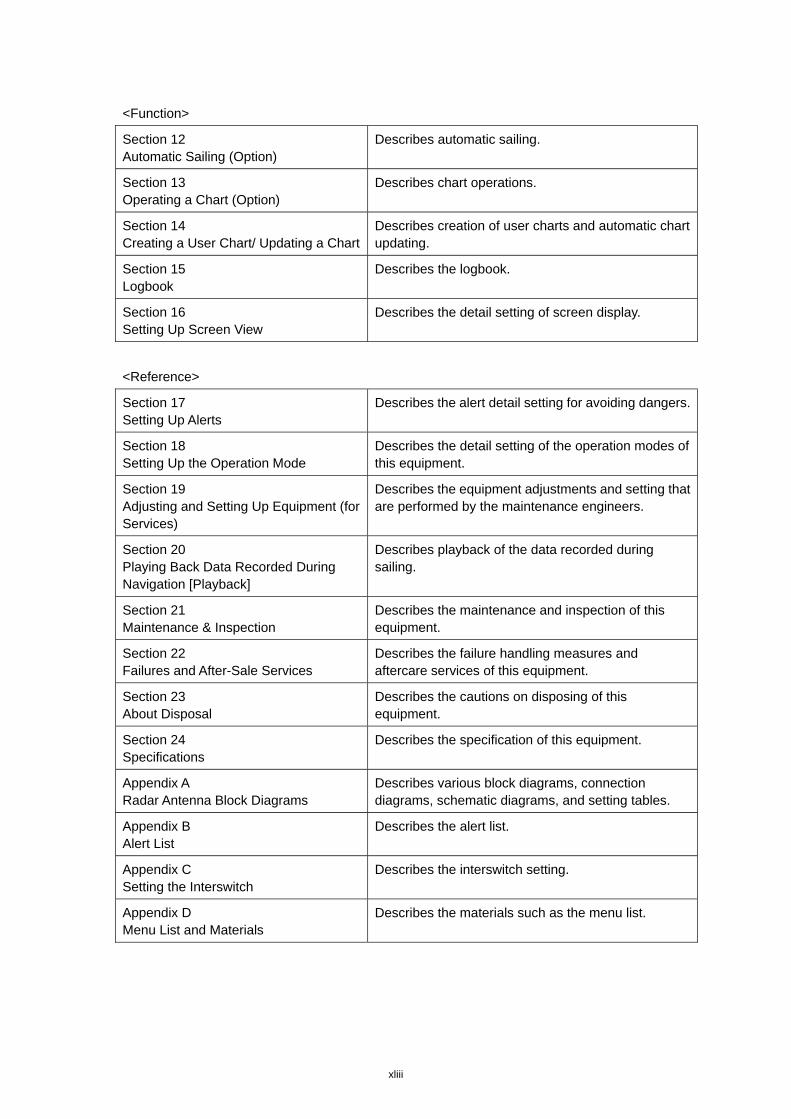
<Function>
Section 12 Automatic Sailing (Option)
Describes automatic sailing.
Section 13 Operating a Chart (Option)
Describes chart operations.
Section 14 Creating a User Chart/ Updating a Chart
Describes creation of user charts and automatic chart updating.
Section 15 Logbook
Describes the logbook.
Section 16 Setting Up Screen View
Describes the detail setting of screen display.
<Reference>
Section 17 Setting Up Alerts
Describes the alert detail setting for avoiding dangers.
Section 18 Setting Up the Operation Mode
Describes the detail setting of the operation modes of this equipment.
Section 19 Adjusting and Setting Up Equipment (for Services)
Describes the equipment adjustments and setting that are performed by the maintenance engineers.
Section 20 Playing Back Data Recorded During Navigation [Playback]
Describes playback of the data recorded during sailing.
Section 21 Maintenance & Inspection
Describes the maintenance and inspection of this equipment.
Section 22 Failures and After-Sale Services
Describes the failure handling measures and aftercare services of this equipment.
Section 23 About Disposal
Describes the cautions on disposing of this equipment.
Section 24 Specifications
Describes the specification of this equipment.
Appendix A Radar Antenna Block Diagrams
Describes various block diagrams, connection diagrams, schematic diagrams, and setting tables.
Appendix B Alert List
Describes the alert list.
Appendix C Setting the Interswitch
Describes the interswitch setting.
Appendix D Menu List and Materials
Describes the materials such as the menu list.
xliv
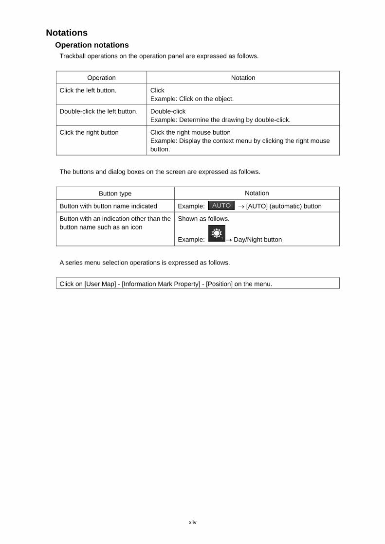
Notations Operation notations
Trackball operations on the operation panel are expressed as follows.
Operation Notation
Click the left button. Click Example: Click on the object.
Double-click the left button. Double-click Example: Determine the drawing by double-click.
Click the right button Click the right mouse button Example: Display the context menu by clicking the right mouse button.
The buttons and dialog boxes on the screen are expressed as follows.
Button type Notation
Button with button name indicated Example: [AUTO] (automatic) button
Button with an indication other than the button name such as an icon
Shown as follows.
Example: Day/Night button
A series menu selection operations is expressed as follows.
Click on [User Map] - [Information Mark Property] - [Position] on the menu.
(1) Contents
2
3
4
5
6
7
8
9
10
11
12
13
14
15
16
17
18
19
20
21
22
23
24
25
26
27
Contents
Basic Operation
Section 1 Overview ........................................................................................ 1-1
1.1 Functions ............................................................................................................................... 1-2
1.2 Features ................................................................................................................................ 1-5
1.3 Components .......................................................................................................................... 1-8
1.4 Structure .............................................................................................................................. 1-14
1.5 General System Diagrams .................................................................................................. 1-45
Section 2 Name and Function of Each Unit ................................................. 2-1
2.1 Name and Main Function of the Operation Unit ................................................................... 2-1
2.1.1 Trackball operation unit ................................................................................................. 2-1
2.1.2 Keyboard operation unit (Option) .................................................................................. 2-2
2.1.3 Display unit ................................................................................................................... 2-4
2.2 Names and Main Functions of the Task Screen Common Sections ..................................... 2-5
2.2.1 Task Switching Button ................................................................................................... 2-6
2.2.2 Right Toolbar ................................................................................................................. 2-6
2.2.3 Left Toolbar ................................................................................................................... 2-7
2.2.3.1 Buttons that are normally displayed ....................................................................... 2-8
2.2.3.2 Buttons that are normally hidden ............................................................................ 2-9
2.2.4 Alert notification area .................................................................................................... 2-9
2.2.5 Key assignment indication area .................................................................................. 2-10
2.2.6 Navigation tools .......................................................................................................... 2-10
2.2.7 Own Ship Information ................................................................................................. 2-11
2.3 Common Information Window ............................................................................................. 2-14
2.3.1 Information monitor windows ...................................................................................... 2-15
2.3.1.1 Target INFO .......................................................................................................... 2-16
2.3.1.2 TT List ................................................................................................................... 2-20
2.3.1.3 AIS List ................................................................................................................. 2-20
2.3.1.4 AIS Detail INFO .................................................................................................... 2-21
2.3.1.5 2nd PPI ................................................................................................................. 2-24
2.3.1.6 Wind/Current Block ............................................................................................... 2-26
2.3.1.7 Conning ................................................................................................................ 2-30
2.3.2 Information reference windows ................................................................................... 2-33
2.3.2.1 Switching between a standard window and an extended window ....................... 2-34
2.3.2.2 AIS MSG Tray ....................................................................................................... 2-36
2.3.2.3 NAVTEX ................................................................................................................ 2-37
2.3.2.4 Active Alert ............................................................................................................ 2-44
2.3.2.5 Alert History .......................................................................................................... 2-45
Contents (2)
2.3.2.6 AIS ........................................................................................................................ 2-46
2.3.2.7 Maintenance INFO ............................................................................................... 2-48
2.4 Names and Main Functions of Each Section of the RADAR Screen .................................. 2-49
2.4.1 Presentation and mode information ............................................................................ 2-50
2.4.2 Radar signal information ............................................................................................. 2-51
2.4.3 Radar system information ........................................................................................... 2-52
2.4.4 Chart Status Information ............................................................................................. 2-53
2.4.5 Own track information ................................................................................................. 2-54
2.4.6 Other ship information................................................................................................. 2-55
2.4.7 Display inside the PPI ................................................................................................. 2-56
2.5 Names and Main Functions of Each Section of the ECDIS Screen (Option) ..................... 2-57
2.5.1 Chart Information Area (ENC/C-MAP) ........................................................................ 2-58
2.5.2 Chart Information Area (RNC) .................................................................................... 2-60
2.5.3 Sub Information Area .................................................................................................. 2-62
2.5.4 Bottom Bar (Sub Information Area) ............................................................................. 2-64
2.5.5 ARCS PIN input dialog box ......................................................................................... 2-66
Section 3 Common Basic Operations ........................................................................ 3-1
3.1 Powering On and Starting ..................................................................................................... 3-1
3.2 Starting Each Mode ............................................................................................................... 3-3
3.3 Basic Operations when using a Trackball ............................................................................. 3-5
3.3.1 Basic trackball operations ............................................................................................. 3-5
3.3.2 Basic click operations ................................................................................................... 3-5
3.3.2.1 Selecting a button ................................................................................................... 3-5
3.3.2.2 Selecting a single object ......................................................................................... 3-5
3.3.2.3 Selecting multiple objects ....................................................................................... 3-6
3.3.3 Basic operations of double-clicking .............................................................................. 3-6
3.3.4 Basic operations of clicking the right button ................................................................. 3-6
3.3.5 Displaying simplified information and operational guide of objects .............................. 3-7
3.3.6 Cursor types .................................................................................................................. 3-8
3.4 Basic Menu Operations ....................................................................................................... 3-10
3.4.1 Opening the menu ...................................................................................................... 3-10
3.4.2 Menu list ...................................................................................................................... 3-14
3.4.3 Closing the menu ........................................................................................................ 3-15
3.5 Basic Dialog Box Operations .............................................................................................. 3-15
3.5.1 Changing dialog box settings ...................................................................................... 3-15
3.5.2 Closing a dialog box.................................................................................................... 3-16
3.5.3 Title Bar ....................................................................................................................... 3-17
3.6 Operation of the Information Monitor Window .................................................................... 3-18
3.6.1 Opening the information monitor window ................................................................... 3-18
3.6.2 Displaying an information monitor window from other than the [Page Selection]
dialog box .................................................................................................................... 3-21
3.7 Confirming and Acknowledging an Alert ............................................................................. 3-22
(3) Contents
2
3
4
5
6
7
8
9
10
11
12
13
14
15
16
17
18
19
20
21
22
23
24
25
26
27
3.7.1 Stopping a buzzer ....................................................................................................... 3-23
3.7.2 Confirming alert contents ............................................................................................ 3-23
3.7.3 Acknowledging the alert .............................................................................................. 3-26
3.7.4 Displaying alert list and alert history ........................................................................... 3-27
3.8 Switching the Day/Night Mode ............................................................................................ 3-32
3.9 Adjusting the Brightness of the Screen and Operation Unit ............................................... 3-34
3.9.1 Adjusting the Brightness of the Screen....................................................................... 3-34
3.9.2 Adjusting the Brightness of the Operation Unit ........................................................... 3-35
3.9.3 [Display Brightness] dialog ......................................................................................... 3-36
3.10 Mouseover Display .............................................................................................................. 3-37
3.10.1 Condition and timing of mouseover display ................................................................ 3-38
3.10.1.1 Starting mouseover display .................................................................................. 3-38
3.10.1.2 Terminating mouseover display ............................................................................ 3-39
3.10.2 How to read mouseover display ................................................................................. 3-40
3.10.2.1 Example of mouseover display ............................................................................ 3-40
3.10.2.2 Mouseover display of an AIS target/tracking target .............................................. 3-40
3.10.2.3 Mouseover display of a buoy/light ........................................................................ 3-41
3.11 MOB (Man Over Board) ...................................................................................................... 3-43
3.12 Setting up the Timer ............................................................................................................ 3-46
3.12.1 Setting up the timer ..................................................................................................... 3-46
3.12.2 Setting up the time ...................................................................................................... 3-46
3.13 Electronic Bearing Line (EBL) and Variable Range Marker (VRM) .................................... 3-47
3.13.1 Electronic Bearing Line (EBL) and Variable range marker (VRM) ............................. 3-47
3.13.2 Displaying the EBL and VRM buttons ......................................................................... 3-48
3.13.2.1 RADAR ................................................................................................................. 3-48
3.13.2.2 ECDIS ................................................................................................................... 3-49
3.13.3 Basic manipulation of EBL/VRM ................................................................................. 3-50
3.13.3.1 Switching the control right of EBL/VRM ............................................................... 3-50
3.13.3.2 Setting up the measurement starting points ......................................................... 3-51
3.13.3.3 Setting the EBL bearing to True/Relative display ................................................. 3-52
3.13.3.4 Setting up the range unit of VRM ......................................................................... 3-52
3.13.3.5 Operating the intersecting point between EBL and VRM ..................................... 3-53
3.14 Cursor AUTO Mode ............................................................................................................. 3-54
3.14.1 No object ..................................................................................................................... 3-55
3.14.2 AIS .............................................................................................................................. 3-55
3.14.3 TT ................................................................................................................................ 3-56
3.14.4 (AZ) Acquisition/Activation Zone ................................................................................. 3-57
3.14.5 AIS filter ...................................................................................................................... 3-58
3.14.6 User Chart ................................................................................................................... 3-58
3.14.6.1 Non-selected object .............................................................................................. 3-58
3.14.6.2 Selected object ..................................................................................................... 3-59
3.14.7 Mariner's Mark/Line .................................................................................................... 3-63
Contents (4)
3.14.7.1 Object in the non-selected state ........................................................................... 3-63
3.14.7.2 Object in selected state ........................................................................................ 3-63
3.14.8 Manual updating ......................................................................................................... 3-65
3.14.8.1 Unsaved object ..................................................................................................... 3-65
3.14.8.2 Saved object ......................................................................................................... 3-65
3.14.8.3 C-MAP chart ......................................................................................................... 3-65
3.14.9 Buoy object ................................................................................................................. 3-65
3.14.10 Light object .................................................................................................................. 3-65
3.14.11 EBL ............................................................................................................................. 3-65
3.14.12 VRM ............................................................................................................................ 3-66
3.14.13 EBL/VRM intersecting point ........................................................................................ 3-66
3.14.14 Node Fixed EBL/VRM ................................................................................................. 3-66
3.14.15 PI ................................................................................................................................. 3-66
3.14.16 WPT of monitored route .............................................................................................. 3-66
3.14.17 Monitoring dragging anchor ........................................................................................ 3-66
3.14.17.1 Object in the unselected state .......................................................................... 3-66
3.14.17.2 Selected state ................................................................................................... 3-66
3.14.18 Planned route .............................................................................................................. 3-67
3.15 Saving the screen that is currently displayed...................................................................... 3-69
3.16 [MULTI] Dial ......................................................................................................................... 3-70
3.16.1 Functions of [MULTI] dial ............................................................................................ 3-70
3.16.2 Functions assigned to [MULTI] dial ............................................................................. 3-70
3.16.2.1 Displaying a screen for setting the function that is assigned ............................... 3-70
3.16.2.2 Changing the function that is assigned ................................................................ 3-70
3.17 Basic Operations of the Software Keyboard ....................................................................... 3-72
3.17.1 Starting a software keyboard ...................................................................................... 3-72
3.17.2 Name and function of each section of the keyboard .................................................. 3-73
3.17.3 Numeric value input example ..................................................................................... 3-76
3.17.4 Character input example ............................................................................................. 3-78
3.18 Setting a Date and a Time (Calendar Operation) ............................................................... 3-81
3.18.1 Details and usage of a calendar picker and a time picker .......................................... 3-82
3.18.1.1 Details of a calendar ............................................................................................. 3-82
3.18.1.2 How to use a calendar .......................................................................................... 3-83
3.19 Help ..................................................................................................................................... 3-84
3.20 Password Input ................................................................................................................... 3-88
3.21 Managing Files with File Manager ...................................................................................... 3-90
3.21.1 Displaying the [File Manager] dialog box .................................................................... 3-90
3.21.2 File management ........................................................................................................ 3-91
3.21.3 Loading and saving files ............................................................................................. 3-94
3.21.3.1 Loading files ......................................................................................................... 3-94
3.21.3.2 Saving files ........................................................................................................... 3-96
3.21.3.3 Deleting data......................................................................................................... 3-97
(5) Contents
2
3
4
5
6
7
8
9
10
11
12
13
14
15
16
17
18
19
20
21
22
23
24
25
26
27
3.22 Returning to a Task Menu by Ending the Operation ........................................................... 3-98
3.23 Terminating this equipment ............................................................................................... 3-100
3.24 Using a DVD Drive ............................................................................................................ 3-101
Section 4 Range and Bearing Measurement Methods ................................ 4-1
4.1 List of Measuring Tools ......................................................................................................... 4-1
4.2 Target Position ...................................................................................................................... 4-2
4.3 Using the Cross-hair Cursor.................................................................................................. 4-3
4.3.1 Cursor readout information area display position ......................................................... 4-3
4.3.1.1 RADAR ................................................................................................................... 4-3
4.3.1.2 ECDIS ..................................................................................................................... 4-4
4.3.2 Measuring the bearing and the range from the own ship's position to the target by
using the cross-hair cursor ........................................................................................... 4-5
4.3.2.1 Measuring by using the cursor information that is displayed by placing the
cursor inside of PPI (RADAR only) ......................................................................... 4-5
4.3.2.2 Measuring by using the [Cursor readout] dialog..................................................... 4-6
4.3.2.3 Switching the cursor bearing between True/Relative ............................................. 4-7
4.3.2.4 Switching the cursor range unit .............................................................................. 4-7
4.4 Using the Range Rings ......................................................................................................... 4-8
4.5 Using the Electronic Bearing Line (EBL) and Variable Range Marker (VRM) .................... 4-10
4.5.1 Measuring a range and a bearing with EBL and VRM ............................................... 4-10
4.5.1.1 Measuring in the trackball operation unit .............................................................. 4-10
4.5.1.2 Measuring with the [EBL] or [VRM] dial on the keyboard operation unit .............. 4-11
4.5.2 Measuring between arbitrary two points ..................................................................... 4-14
4.5.3 Manipulating EBL/VRM with the context menu (ECDIS only) .................................... 4-16
4.5.3.1 Manipulating EBL/VRM with [Dropped EBL/VRM] - [Make EBL1/VRM1] or
[Make EBL2/VRM2] .............................................................................................. 4-17
4.5.3.2 Manipulating EBL with [Dropped EBL/VRM] - [Make EBL1] or [Make EBL2] ...... 4-18
4.5.3.3 Manipulating VRM with [Dropped EBL/VRM] - [Make VRM1] or [Make VRM2] ... 4-19
4.5.3.4 Manipulating EBL/VRM with [Dropped EBL/VRM] - [Move base point of
EBL1/VRM1] or [Move base point of EBL2/VRM2] .............................................. 4-19
4.5.3.5 Manipulating EBL/VRM with [CCRP EBL/VRM] - [Make EBL1/VRM1] or
[Make EBL2/VRM2] .............................................................................................. 4-20
4.5.3.6 Manipulating EBL with [CCRP EBL/VRM] - [Make EBL1] or [Make EBL2] .......... 4-21
4.5.3.7 Manipulating VRM with [CCRP EBL/VRM] - [Make VRM1] or [Make VRM2] ...... 4-21
4.6 Using Parallel Index Lines (PI) ............................................................................................ 4-22
4.6.1 Description of a parallel index line .............................................................................. 4-22
4.6.2 Displaying parallel index lines ..................................................................................... 4-22
4.6.2.1 Displaying parallel index lines in the trackball operation unit ............................... 4-22
4.6.2.2 Displaying parallel index lines in the keyboard operation unit .............................. 4-23
4.6.2.3 Description of the [PI Menu] dialog ...................................................................... 4-24
4.6.3 Setting all the parallel index lines concurrently (All mode) ......................................... 4-28
4.6.3.1 Changing the bearing/interval of parallel index lines in the trackball operation
Contents (6)
unit (All mode) ...................................................................................................... 4-30
4.6.4 Setting parallel index lines individually (Individual mode) ........................................... 4-31
4.6.4.1 Changing the bearing/interval/end point of parallel index lines in the trackball
operation unit (Individual mode) ........................................................................... 4-34
4.6.5 Displaying lines at equal interval on the left and right sides of the own ship's
position (Track mode) ................................................................................................. 4-35
4.6.5.1 Changing the bearing/interval of parallel index lines with the trackball (Track
mode) .................................................................................................................... 4-37
4.6.6 Displaying two intersecting lines (Equiangular mode) ................................................ 4-38
4.6.6.1 Changing the bearing of two intersecting lines in the trackball operation unit
(Equiangular mode) .............................................................................................. 4-39
4.6.7 Setting parallel index lines in the keyboard operation unit ......................................... 4-40
4.6.7.1 Operation in All mode ........................................................................................... 4-40
4.6.7.2 Operation in Individual mode ................................................................................ 4-41
4.6.7.3 Operation in Track mode ...................................................................................... 4-41
4.6.7.4 Operation in Equiangular mode ............................................................................ 4-42
4.7 Using the EBL Maneuver .................................................................................................... 4-43
4.7.1 Displaying the [EBL Maneuver Setting] dialog box ..................................................... 4-43
4.7.2 Clearing the display of maneuver curve ..................................................................... 4-44
4.7.3 Setting the creation conditions of the EBL Maneuver ................................................. 4-44
4.7.4 Creating an EBL maneuver curve ............................................................................... 4-45
4.8 Connecting Own Ship and the Specified Fixed Position with EBL and the VRM Marker
(Node Fixed EBL/VRM Function) ........................................................................................ 4-47
4.8.1 Displaying the [Node Fixed EBL/VRM] dialog box ..................................................... 4-47
4.8.2 Description of [Node Fixed EBL/VRM] dialog box ...................................................... 4-48
4.8.3 Creating a new Node Fixed EBL/VRM ....................................................................... 4-48
4.8.4 Cancelling the Node Fixed EBL/VRM function ........................................................... 4-49
4.9 Measuring the Own Ship's Position Manually (LOPs Fixing Function of Manual position
fix) ........................................................................................................................................ 4-50
4.9.1 Displaying the [Manual position fix] dialog box ........................................................... 4-50
4.9.2 Description of the [LOPs Fixing] tab of the [Manual position fix] dialog box ............... 4-51
4.9.3 Creating LOP .............................................................................................................. 4-54
4.9.3.1 Creating bearing LOP ........................................................................................... 4-54
4.9.3.2 Creating distance LOP ......................................................................................... 4-56
4.9.4 Measuring the own ship's position in cross bearing fix ............................................... 4-57
4.9.4.1 Automatic position fixing ....................................................................................... 4-58
4.9.4.2 Automatic offset .................................................................................................... 4-59
4.9.4.3 Manual position fixing ........................................................................................... 4-61
4.9.4.4 When there are three or more LOPs or TPLs ...................................................... 4-62
4.9.4.5 Setting a plotted position ...................................................................................... 4-64
4.9.5 Measuring the own ship's position with Running Fix .................................................. 4-66
4.9.6 Measuring the own ship's position with other methods .............................................. 4-70

(7) Contents
2
3
4
5
6
7
8
9
10
11
12
13
14
15
16
17
18
19
20
21
22
23
24
25
26
27
4.10 Offsetting the Own Ship's Position Manually (Position Offset Function of Manual position
fix) ........................................................................................................................................ 4-71
4.10.1 Displaying the [Manual position fix] dialog box ........................................................... 4-71
4.10.2 Description of the [Position Offset] tab of the [Manual position fix] dialog box ........... 4-73
4.10.3 Setting the offset amount that is input in the [Enter Offset] dialog as the offset
position ........................................................................................................................ 4-74
4.10.4 Setting the position on the chart on which the mouse button was clicked as the
offset position .............................................................................................................. 4-75
4.10.5 Recording LOPs Fixing operation in the logbook ....................................................... 4-76
4.10.6 Offsetting the own ship position .................................................................................. 4-78

Contents (8)
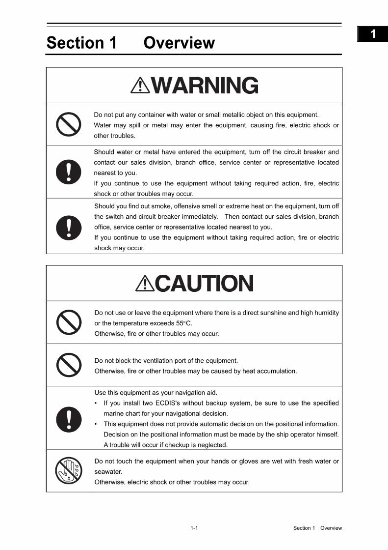
1-1 Section 1 Overview
1
2
3
4
5
6
7
8
9
10
11
12
13
14
15
16
17
18
19
20
21
22
23
24
25
26
27
付録
Section 1 Overview
Do not put any container with water or small metallic object on this equipment.
Water may spill or metal may enter the equipment, causing fire, electric shock or
other troubles.
Should water or metal have entered the equipment, turn off the circuit breaker and
contact our sales division, branch office, service center or representative located
nearest to you.
If you continue to use the equipment without taking required action, fire, electric
shock or other troubles may occur.
Should you find out smoke, offensive smell or extreme heat on the equipment, turn off
the switch and circuit breaker immediately. Then contact our sales division, branch
office, service center or representative located nearest to you.
If you continue to use the equipment without taking required action, fire or electric
shock may occur.
Do not use or leave the equipment where there is a direct sunshine and high humidity
or the temperature exceeds 55C.
Otherwise, fire or other troubles may occur.
Do not block the ventilation port of the equipment.
Otherwise, fire or other troubles may be caused by heat accumulation.
Use this equipment as your navigation aid.
• If you install two ECDIS's without backup system, be sure to use the specified
marine chart for your navigational decision.
• This equipment does not provide automatic decision on the positional information.
Decision on the positional information must be made by the ship operator himself.
A trouble will occur if checkup is neglected.
Do not touch the equipment when your hands or gloves are wet with fresh water or
seawater.
Otherwise, electric shock or other troubles may occur.
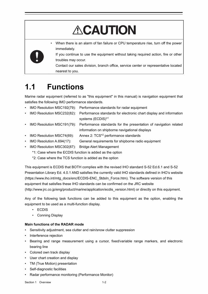
Section 1 Overview 1-2
• When there is an alarm of fan failure or CPU temperature rise, turn off the power
immediately.
If you continue to use the equipment without taking required action, fire or other
troubles may occur.
Contact our sales division, branch office, service center or representative located
nearest to you.
1.1 Functions Marine radar equipment (referred to as "this equipment" in this manual) is navigation equipment that
satisfies the following IMO performance standards.
• IMO Resolution MSC192(79): Performance standards for radar equipment
• IMO Resolution MSC232(82): Performance standards for electronic chart display and information
systems (ECDIS)*1
• IMO Resolution MSC191(79): Performance standards for the presentation of navigation related
information on shipborne navigational displays
• IMO Resolution MSC74(69): Annex 2: TCS*2 performance standards
• IMO Resolution A.694(17): General requirements for shipborne radio equipment
• IMO Resolution MSC302(87): Bridge Alert Management
*1: Case where the ECDIS function is added as the option
*2: Case where the TCS function is added as the option
This equipment is ECDIS that BOTH complies with the revised IHO standard S-52 Ed.6.1 and S-52
Presentation Library Ed. 4.0.1 AND satisfies the currently valid IHO standards defined in IHO’s website
(https://www.iho.int/mtg_docs/enc/ECDIS-ENC_StdsIn_Force.htm). The software version of this
equipment that satisfies these IHO standards can be confirmed on the JRC website
(http://www.jrc.co.jp/eng/product/marine/application/ecdis_version.html) or directly on this equipment.
Any of the following task functions can be added to this equipment as the option, enabling the
equipment to be used as a multi-function display.
• ECDIS
• Conning Display
Main functions of the RADAR mode
• Sensitivity adjustment, sea clutter and rain/snow clutter suppression
• Interference rejection
• Bearing and range measurement using a cursor, fixed/variable range markers, and electronic
bearing line
• Colored own track display
• User chart creation and display
• TM (True Motion) presentation
• Self-diagnostic facilities
• Radar performance monitoring (Performance Monitor)
1-3 Section 1 Overview
1
2
3
4
5
6
7
8
9
10
11
12
13
14
15
16
17
18
19
20
21
22
23
24
25
26
27
付録
• Target tracking functions (manual/automatic target acquisition and tracking, vector and trail displays
and alarm displays)
• 8-unit switchover (Interswitch) function (Option)
• Electronic navigational chart display*1 (Option)
*1: The following databases can be displayed (ARCS cannot be displayed.)
- S-57 Ed3.0/3.1
- S-63
- C-Map Ed3.0 Professional/Professional+
- C-Map ENC
- C-Map CAES
- Jeppesen PRIMAR ECDIS Service
Main functions of the ECDIS mode
• The following databases can be displayed.
- S-57 Ed3.0/3.1
- S-63
- C-Map Ed3.0 Professional/Professional+
- C-Map ENC
- CAES
- Jeppesen PRIMAR ECDIS Service
- ARCS
• Own ship’s track display and planned-route display on the electronic chart
• Automatic checking of the safety contours and dangerous areas of the own ship (not available for
ARCS)
• TT target display and AIS target display on the electronic chart
• Overlay of radar echo on the electronic chart
• True/Relative motion display
• North-up/Course-up/Head-up/Waypoint-up display
• Display of route information such as latitude/longitude at destinations, bearings/ranges up to
waypoints, and planned arrival time
• Availability of two EBLs/VRMs
• Writing of memos with alphabetic characters into the electronic chart
• Display of information such as the date/time, current position, heading, and ship’s speed
• Selection of colors (conforming to the IMO/IHO) suitable for the daytime, nighttime, dawn and
evening
• Editing of route information
Addition, deletion, and modification of WPTs on the electronic chart or the list
Calculation of the distance between WPTs, bearings, and planned arrival time
Up to 512 WPTs per route
Checking on the crossing of the safety contours and dangerous areas on created routes
• Route tracking (option)
• Course change
• Safety contours crossing alarm
• Dangerous areas approaching warning
• Waypoint arrival warning
• Off-track warning

Section 1 Overview 1-4
• Logging of navigation information onto the SSD
• Own ship’s playback using logged data
Note
This manual describes the methods of handling the RADAR mode and the ECDIS mode, however,
this manual does not describe the handling method of the Conning mode. For the handling of the
conning mode, refer to the “JAN-7202/9202 Conning Display Instruction Manual”.
1-5 Section 1 Overview
1
2
3
4
5
6
7
8
9
10
11
12
13
14
15
16
17
18
19
20
21
22
23
24
25
26
27
付録
1.2 Features This MFD has the following features:
Common functions:
Utilization of an icon menu
Intuitive operation system based on the workflow
High-resolution large screen
Message reception notification function
Notifies arrival of a new AIS message and so on with a badge.
Utilization of a common information window
Enables display of target information and simple conning information (wind direction/wind speed
information, etc.) with a simple switching operation.
Display of chart information read results by grouping
Enables immediate access to the required information.
Display of the cause of alert as well as the action guideline
Equipped with the Help function
The built-in HTML Help enables the search of operation methods in this equipment instead of the
hardcopy manual whenever required.
Visual highlight of target symbols
Enables identification of the target that matches the condition such as the sailing direction, ship’s
length, and ship’s type by highlighted display.
Equipped with the white list type virus protection function of Trend Micro Incorporated
RADAR function:
Realized a clear large screen with its high resolution.
By using the high definition 26inch color LCD of 1920×1200 pixels, radar image display of
diameter 320mm or more is secured. Image presentation of high resolution is also possible in
near ranges.
Section 1 Overview 1-6
Equipped with high performance radar signal processing ASIC BLZZARD™ of new design
By eliminating unnecessary signals (clutters) from the radar video signals obtained from a wide
dynamic range receiver, target detection is enhanced.
Target tracking (TT) function by utilizing the latest technology
By using the latest high-speed DSP and tracking algorithm, the target acquisition/tracking
performance is improved, achieving stable operation for target tracking inside of clutters also.
- Acquisition and tracking of up to 100 targets as standard
- Expressing danger status with a sound and shape and color of a symbol
- Equipped with a trial maneuvering function
- Capable of 10-color coded display by storing target trails.
Background tracking function (Full-screen acquisition function)
Since detectable radar echoes are acquired and tracked automatically in background, the vector
can be displayed immediately after initial acquisition.
Top screen with strictly selected information
Information that is constantly displayed on the Top screen of the radar is strictly selected to enable
users to find the required information effortlessly.
Sortable TT/AIS list
Provides a sortable TT/AIS list (for instance in the TCPA descending order) to enable users to
check the ship in the highest danger.
Dual PPI display
Capable of monitoring of near-range images and far-range images concurrently with one radar
(JMR-9200 Series only).
Superimposed display of radar image, chart, and own ship’s trail
Capable of superimposed display of a user-created map, an imported chart of a coastline and
buoys, own ship’s trail, and other ship’s trails, radar images, and radar trails in all the display
modes including Head Up display.
Improved Day/Night function
The Day/Night function supports up to 5 types of display screen color combinations and enables
users to reproduce screen colors suitable for the user utilization environment with simple key
operations. The function provides easy-to-understand screens through color coded radar images
and a variety of graphics.
Built-in self-diagnosis program
By constantly monitoring all the system functions, this program displays a warning message on
the screen at detection of function deterioration and issues a warning sound. The system function
test can be performed easily during normal operation (excluding some tests).
1-7 Section 1 Overview
1
2
3
4
5
6
7
8
9
10
11
12
13
14
15
16
17
18
19
20
21
22
23
24
25
26
27
付録
Performance monitor function
This function monitors radar performance (transmission output and reception sensitivity) on the
screen.
Interswitch function (Option)
By connecting to the interswitch unit (optional), up to 8 radars can be inter-switched with simple
operations.
Up to 4 units: An interswitch unit separate type from the indicator and cable for connecting each
indicator are necessary.
Up to 8 units: An interswitch unit separate type from the indicator and cable for connecting each
indicator are necessary.
ECDIS function:
This function minimizes the information that is displayed constantly and expands the chart
display area.
- Can display vector charts (ENC and C-MAP) and raster chart (ARCS).
- Realizes safer sailing through the safety contour line and crossing and approaching danger
zone monitoring function. (Excluding ARCS)
- Realizes high operability through high-speed drawing and high-speed processing.
- Facilitates creation of user charts.
- Applies a multi-display screen that can display two charts concurrently. (ARCS and C-MAP
Ed.3 cannot be displayed concurrently with a chart of a different type)
- Enables a course plan with multi-view.
- Can display a wide view screen while a single chart or multi-view is displayed.
- Enables creation of a route plan with the table editing function and the graphic editing function.
- Can create an alternative route while sailing.
- Automatic sailing is enabled by connecting with Auto Pilot. (option)
- The playback function enables checking of the sailed routes.
- The S-57 chart can be updated. (Chart Maintenance)
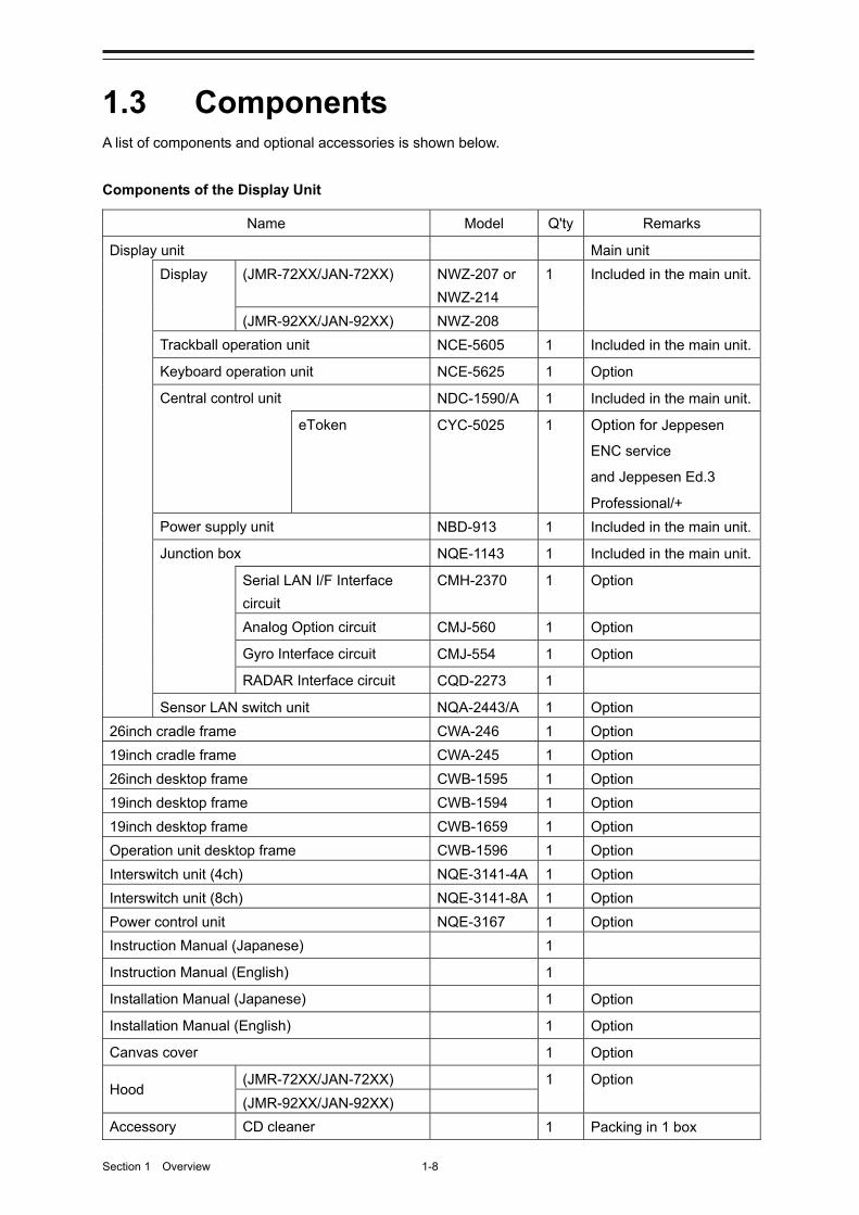
Section 1 Overview 1-8
1.3 Components A list of components and optional accessories is shown below.
Components of the Display Unit
Name Model Q'ty Remarks
Display unit Main unit
Display (JMR-72XX/JAN-72XX) NWZ-207 or
NWZ-214
1 Included in the main unit.
(JMR-92XX/JAN-92XX) NWZ-208
Trackball operation unit NCE-5605 1 Included in the main unit.
Keyboard operation unit NCE-5625 1 Option
Central control unit NDC-1590/A 1 Included in the main unit.
eToken CYC-5025 1 Option for Jeppesen
ENC service
and Jeppesen Ed.3
Professional/+
Power supply unit NBD-913 1 Included in the main unit.
Junction box NQE-1143 1 Included in the main unit.
Serial LAN I/F Interface
circuit
CMH-2370 1 Option
Analog Option circuit CMJ-560 1 Option
Gyro Interface circuit CMJ-554 1 Option
RADAR Interface circuit CQD-2273 1
Sensor LAN switch unit NQA-2443/A 1 Option
26inch cradle frame CWA-246 1 Option
19inch cradle frame CWA-245 1 Option
26inch desktop frame CWB-1595 1 Option
19inch desktop frame CWB-1594 1 Option
19inch desktop frame CWB-1659 1 Option
Operation unit desktop frame CWB-1596 1 Option
Interswitch unit (4ch) NQE-3141-4A 1 Option
Interswitch unit (8ch) NQE-3141-8A 1 Option
Power control unit NQE-3167 1 Option
Instruction Manual (Japanese) 1
Instruction Manual (English) 1
Installation Manual (Japanese) 1 Option
Installation Manual (English) 1 Option
Canvas cover 1 Option
Hood (JMR-72XX/JAN-72XX) 1 Option
(JMR-92XX/JAN-92XX)
Accessory CD cleaner 1 Packing in 1 box

1-9 Section 1 Overview
1
2
3
4
5
6
7
8
9
10
11
12
13
14
15
16
17
18
19
20
21
22
23
24
25
26
27
付録
Spare parts for the main unit 1 Packing in 1 box
Spare parts for the junction box 1 Option
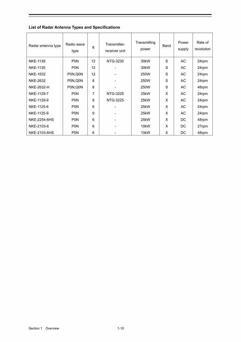
Section 1 Overview 1-10
List of Radar Antenna Types and Specifications
Radar antenna type Radio wave
type ft
Transmitter-
receiver unit
Transmitting
power Band
Power
supply
Rate of
revolution
NKE-1139
NKE-1130
NKE-1632
NKE-2632
NKE-2632-H
NKE-1129-7
NKE-1129-9
NKE-1125-6
NKE-1125-9
NKE-2254-6HS
NKE-2103-6
NKE-2103-6HS
P0N
P0N
P0N,Q0N
P0N,Q0N
P0N,Q0N
P0N
P0N
P0N
P0N
P0N
P0N
P0N
12
12
12
8
8
7
9
6
9
6
6
6
NTG-3230
-
-
-
-
NTG-3225
NTG-3225
-
-
-
-
-
30kW
30kW
250W
250W
250W
25kW
25kW
25kW
25kW
25kW
10kW
10kW
S
S
S
S
S
X
X
X
X
X
X
X
AC
AC
AC
AC
AC
AC
AC
AC
AC
DC
DC
DC
24rpm
24rpm
24rpm
24rpm
48rpm
24rpm
24rpm
24rpm
24rpm
48rpm
27rpm
48rpm
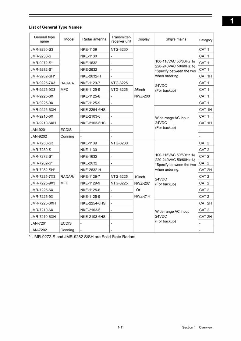
1-11 Section 1 Overview
1
2
3
4
5
6
7
8
9
10
11
12
13
14
15
16
17
18
19
20
21
22
23
24
25
26
27
付録
List of General Type Names
General type name
Model Radar antenna Transmitter- receiver unit
Display Ship’s mains Category
JMR-9230-S3
RADAR/
MFD
NKE-1139 NTG-3230
26inch
NWZ-208
100-115VAC 50/60Hz 1 220-240VAC 50/60Hz 1 *Specify between the two when ordering. 24VDC (For backup)
CAT 1
JMR-9230-S NKE-1130 - CAT 1
JMR-9272-S* NKE-1632 - CAT 1
JMR-9282-S* NKE-2632 - CAT 1
JMR-9282-SH* NKE-2632-H - CAT 1H
JMR-9225-7X3 NKE-1129-7 NTG-3225 CAT 1
JMR-9225-9X3 NKE-1129-9 NTG-3225 CAT 1
JMR-9225-6X NKE-1125-6 - CAT 1
JMR-9225-9X NKE-1125-9 - CAT 1
JMR-9225-6XH NKE-2254-6HS -
Wide range AC input 24VDC (For backup)
CAT 1H
JMR-9210-6X NKE-2103-6 - CAT 1
JMR-9210-6XH NKE-2103-6HS - CAT 1H
JAN-9201 ECDIS - - -
JAN-9202 Conning - - -
JMR-7230-S3
RADAR/
MFD
NKE-1139 NTG-3230
19inch
NWZ-207
Or
NWZ-214
100-115VAC 50/60Hz 1 220-240VAC 50/60Hz 1 *Specify between the two when ordering. 24VDC (For backup)
CAT 2
JMR-7230-S NKE-1130 - CAT 2
JMR-7272-S* NKE-1632 - CAT 2
JMR-7282-S* NKE-2632 - CAT 2
JMR-7282-SH* NKE-2632-H - CAT 2H
JMR-7225-7X3 NKE-1129-7 NTG-3225 CAT 2
JMR-7225-9X3 NKE-1129-9 NTG-3225 CAT 2
JMR-7225-6X NKE-1125-6 - CAT 2
JMR-7225-9X NKE-1125-9 - CAT 2
JMR-7225-6XH NKE-2254-6HS -
Wide range AC input 24VDC (For backup)
CAT 2H
JMR-7210-6X NKE-2103-6 - CAT 2
JMR-7210-6XH NKE-2103-6HS - CAT 2H
JAN-7201 ECDIS - - -
JAN-7202 Conning - - -
*: JMR-9272-S and JMR-9282 S/SH are Solid State Radars.
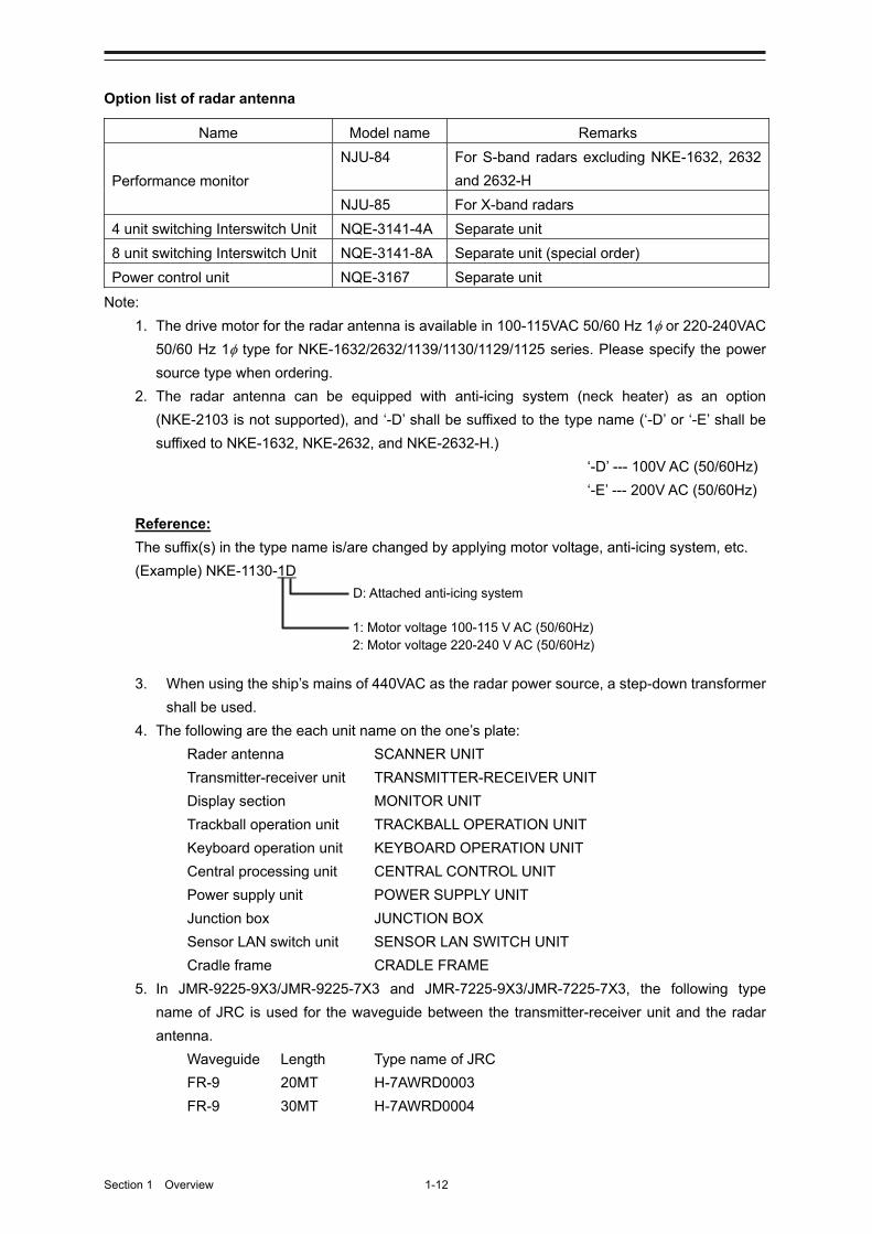
Section 1 Overview 1-12
Option list of radar antenna
Name Model name Remarks
Performance monitor
NJU-84 For S-band radars excluding NKE-1632, 2632
and 2632-H
NJU-85 For X-band radars
4 unit switching Interswitch Unit NQE-3141-4A Separate unit
8 unit switching Interswitch Unit NQE-3141-8A Separate unit (special order)
Power control unit NQE-3167 Separate unit
Note:
1. The drive motor for the radar antenna is available in 100-115VAC 50/60 Hz 1 or 220-240VAC
50/60 Hz 1 type for NKE-1632/2632/1139/1130/1129/1125 series. Please specify the power
source type when ordering.
2. The radar antenna can be equipped with anti-icing system (neck heater) as an option
(NKE-2103 is not supported), and ‘-D’ shall be suffixed to the type name (‘-D’ or ‘-E’ shall be
suffixed to NKE-1632, NKE-2632, and NKE-2632-H.)
‘-D’ --- 100V AC (50/60Hz)
‘-E’ --- 200V AC (50/60Hz)
Reference:
The suffix(s) in the type name is/are changed by applying motor voltage, anti-icing system, etc.
(Example) NKE-1130-1D
3. When using the ship’s mains of 440VAC as the radar power source, a step-down transformer
shall be used.
4. The following are the each unit name on the one’s plate:
Rader antenna SCANNER UNIT
Transmitter-receiver unit TRANSMITTER-RECEIVER UNIT
Display section MONITOR UNIT
Trackball operation unit TRACKBALL OPERATION UNIT
Keyboard operation unit KEYBOARD OPERATION UNIT
Central processing unit CENTRAL CONTROL UNIT
Power supply unit POWER SUPPLY UNIT
Junction box JUNCTION BOX
Sensor LAN switch unit SENSOR LAN SWITCH UNIT
Cradle frame CRADLE FRAME
5. In JMR-9225-9X3/JMR-9225-7X3 and JMR-7225-9X3/JMR-7225-7X3, the following type
name of JRC is used for the waveguide between the transmitter-receiver unit and the radar
antenna.
Waveguide Length Type name of JRC
FR-9 20MT H-7AWRD0003
FR-9 30MT H-7AWRD0004
D: Attached anti-icing system
1: Motor voltage 100-115 V AC (50/60Hz) 2: Motor voltage 220-240 V AC (50/60Hz)

1-13 Section 1 Overview
1
2
3
4
5
6
7
8
9
10
11
12
13
14
15
16
17
18
19
20
21
22
23
24
25
26
27
付録
6. In JMR-9230-S3 and JMR-7230-S3, the following type name of JRC is used for the coaxial
cable between the transmitter-receiver unit and the radar antenna.
Coaxial cable Length Type name of JRC
HF-20D 30MT HF-20D (30MT)
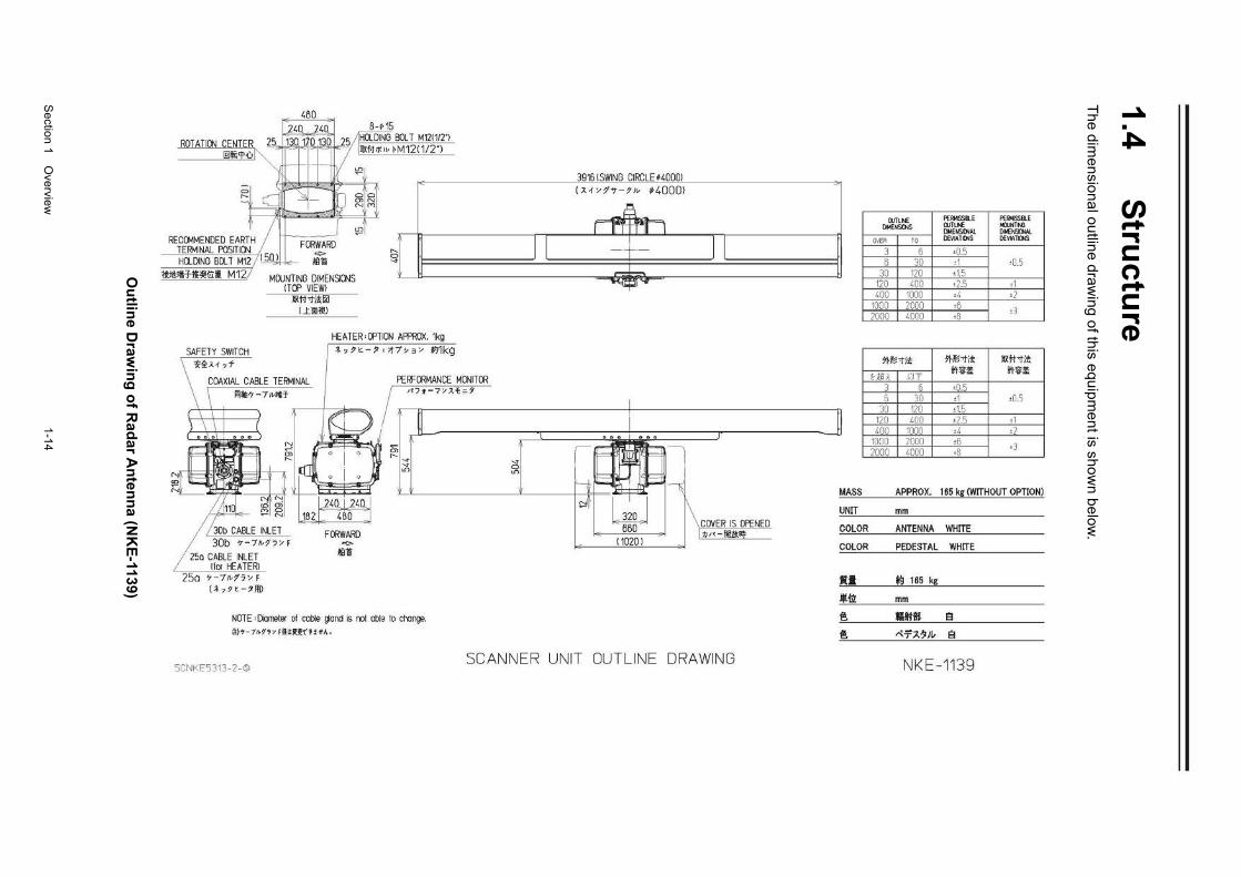
Section 1 O
verview
1-14
1.4 S
tructu
re T
he dimensional outline draw
ing of this equipment is show
n below.
Ou
tline D
rawin
g o
f Rad
ar An
tenn
a (NK
E-1139)
RECCMMENDED EARTH TERMINAL POSITI()IJ HQ._DING BCU M12 I I 5
llJllnHlii'IHi:i M 12
SAFETY SWITCH 'li~J.1 ·Jf
25a 7-7 1,7'7"' F I* ., n -,111>
MDJNTING DIMEN:JCNS ITOO VIEWI
littt-t!Ul LtiiDlV
" ':?
HEATER • OOTION APPROX. 1kg *· 9 ~- , .~7 ~ 3 >' ~1kg
FERFCRMANCE MONITOR
It~* n J.t= '
,ll CJ)
" "' "' "'
NOTE • Demeter oi cable gar.d is nol able to crange. it)>-7~17> Ftl~l!OHA .
39151SWING CIRCLE ;40001 (J. 1 >':1"'t - 91• ~4000>
. . . ... IF ~~~ I "' D
It:: I on
-l f===o !:t:: ' 't
I ~ W I \ covER IS OPENED 650 1 n ,, ll!IM;_IIi_
11020 ) __,.
SCNKE5313 -2-~ SCANNER UNIT OUTLINE DRAWING
]
MASS
UNIT
COLOR
COLOR
•• -*lfl ~
~
[lJl LI'<E f'ERI<ISSil.E f'E RI<ISSil.E IJOMENSOIS CIJTLt.E llolllJt.lTNl
DME~Al DI>ENSO<AL O'IER TO DEVIATDJS DEYIA.TDJS
3 6 •0.5 6 30 •1 •0.5
30 120 •1.5 120 400 •2.5 •1 400 1000 •4 •2
1000 2000 •6 2000 4000 •8
d
5'1-~-tit mt~-t;t littl -1)'!
u~~ rn i'!:%:1! i'fli:i!
3 6 ±0.5 B 30 •1 ±0.5
30 120 ±1.5 120 400 •2.5 •1 400 1000 ·4 ±2
1000 2000 •6 •3 2000 4000 •8
APPRO X. 165 kg (WITHOUT OPTION)
mm
ANTENNA WHITE
PEDESTAL WHITE
ts 165 kg
mm
tiM. 8 "7'7-:l!J(, 8
NKE-1139
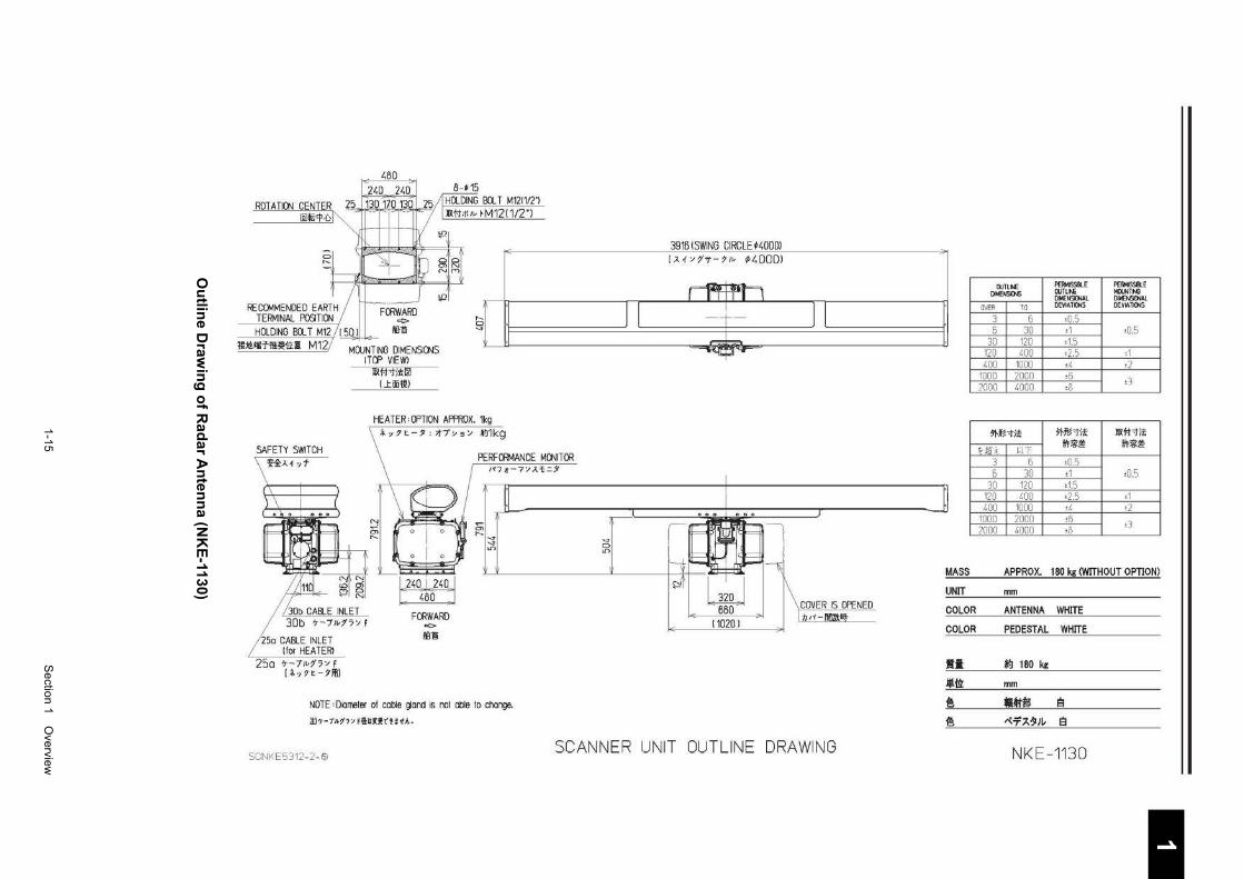
1-15
S
ection 1 Overview
1 2 3 4 5 6 7 8 9
10
11
12
13
14
15
16
17
18
19
20
21
22
23
24
25
26
27
付録
O
utlin
e Draw
ing
of R
adar A
nten
na (N
KE
-1130)
RE Cet.1MENDED EARTH TERMINAL POSITION HQ DING BOLT M12 / I 5
lt:!l!litiT-lit~i;Liii M12
SAFETY SWITCH i1:J.~,f
30b CABLE INLET 30b 7-71v~7 '/ F
~5o CABLE INLET Jfor HEATER!
25a 7-7~>~7'/ r 1-*·,?t-71!1)
,.._ ~
HEATER' CFTION APPROX. 1kg '·7~-,,~7~.~ ~1kg
FORWARD "(:>
ll'l"B
PERFORMANCE MONITOR fl>t-7'/J.'I:-:i'
;; "' 1'-.
~ "' "' .n
NOTE ,Domeier of cable !jond is nol able to crarge.
it)'T-7/I.?"'y FllUU"Oltt...
39161SWING CIRCLE '4000l [J.1 Y 1't-?lv ¢4000)
. . . ... _) I
I ~~ ] ) "' c:::>
HIE~~~~ Lr>
~t ~ I\ COVER IS OPENED 660 r11,,-oo~ 110201
--" ><0-
SCNKE5312-2 -~ SCANNER UNIT OUTLINE DRAWING
]
MASS
UNIT
COLOR
COLOR
•• .l(!.il):
~
~
[)Jl lt..E PERI<ISSIII.E PERMISSIILE [)MENSOIS ClJTLt.E Mll.JNTNl
DNENSICNAL DI~Al
OVER TO DEVIATICJ6 DEVLt\1015
3 6 ±0.5 6 30 ±1 ±0.5
30 120 ±1.5 120 400 ±2.5 ±1 400 1000 ±4 •2
1000 2000 ·6 ·3 2000 4000 ·8
~~"tit ~~~"tit llil.fi-tit
Hi! ~ UT O'IY6:~ !'t~~
3 6 ±0.5 5 30 •1 ±0.5
30 120 ±1.5 120 400 ±2.5 ±1 400 1000 ±4 ±2
1000 2000 ±6 ±3 2000 4000 ±8
APPRO X. 180 kg (WITHOUT OPTION)
mm
ANTENNA WHITE
PEDESTAL WHITE
*\) 180 kg
mm
Cit'M 9 ~-T7.1ZJI- 9
NKE-1130
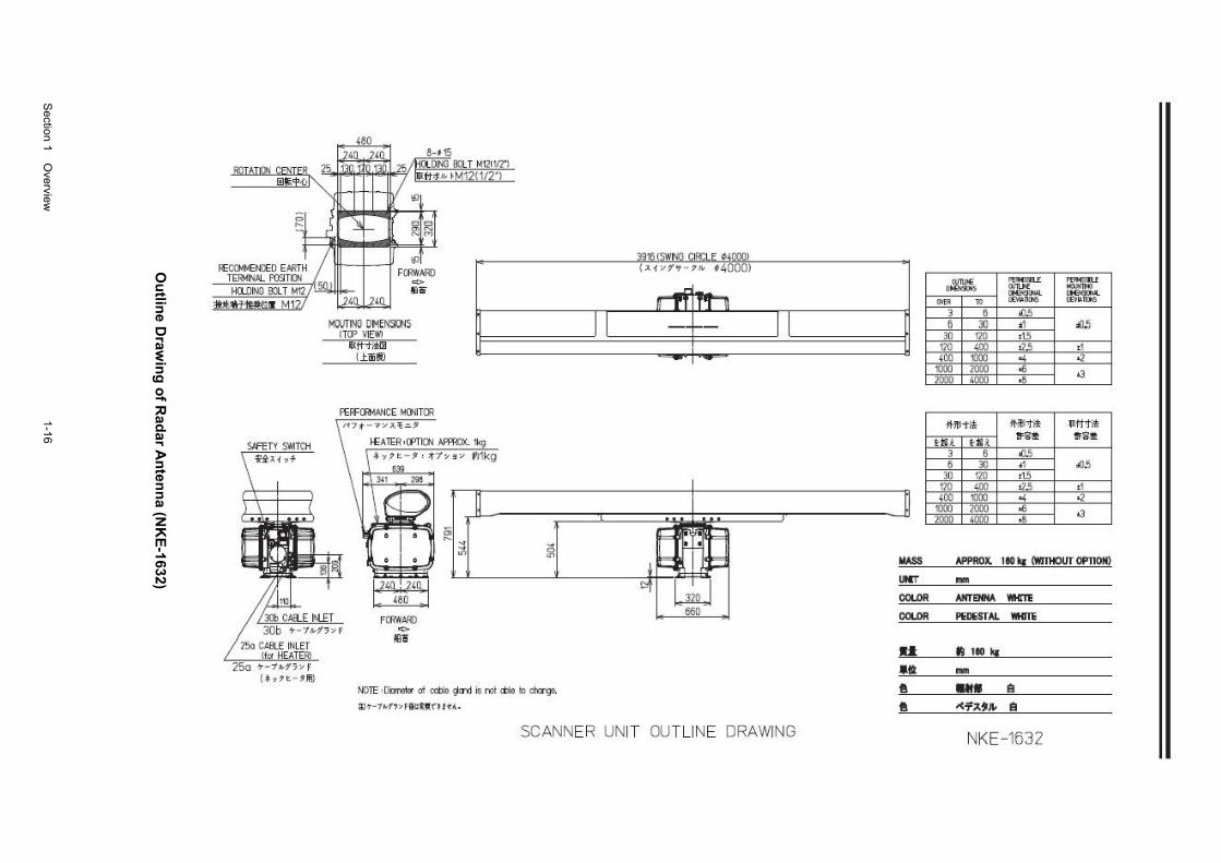
Section 1 O
verview
1-16
Ou
tline D
rawin
g o
f Rad
ar An
tenn
a (NK
E-1632)
~OG!ti.ENCED EARTH TERMINM. POSITIDtl H(l()INO OOL T Ml2
1tJU\TUt;;ll M12.'
( .f. ?7 t - ?M}
: 480
FC«H~'11) ... e ;;
MOIJTING DMENSICNS IT<P VIEWI
llft"t~ Ltiiil!ll
HEATERo<PTICN Afffi:lX. tkg * 77 ~-7 ~ ~7~ 3 ~ ~kg
639
~ ~ FC«II~
"'" ~-
ii.il ~I iii
NOTE •Oilrellr ot <Ob1e g<r<l is rot <tlle IX> ch:rge.
~'T-7J.f,:;f&lfU'(! I t A.
39161SWNG CI~LE 040001 (>. f ~1'f -7" #4000!
SCANNER UNIT OU TLINE DRAWING
IIASS
UICT
COI.OR
COI.OR
u •• e e
""""' ~ .......... '""""" """"" .......... <>EI<I""-
'"" TO CE:'t\l.D!h'S ro~n{);S
3 6 10.5 6 30 ., .0.5
30 120 t1.5 120 400 a:; • I 400 1000 "' .:.?
t)IJl) 2000 .0 l3 2000 4000 •8
11-lll"til< !!-$'!"!!; llf'ftl!;
ua Uli. :fi~ ~<I~
3 6 10.5 5 30 •1 .o:;
30 120 t1.5 120 400 a:; d 400 1000 "' .:.?
mo 2000 .0 l3 2000 4000 •8
APPRDX. 110 k1 <WlTHOIIT OPllON) ... ANTENNA WHm
PEDESTAL WKITE
tl 110 "' ... ... e -<i'~')l. e
NKE-1632
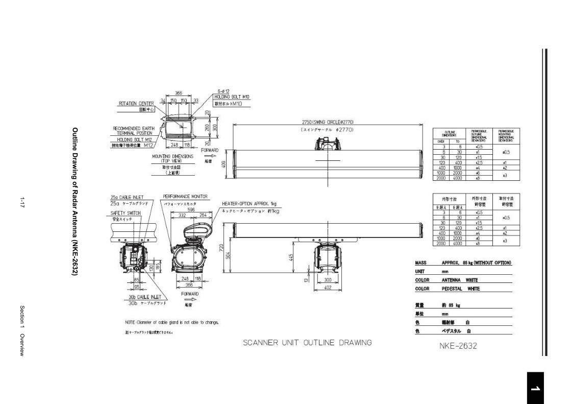
1-17
S
ection 1 Overview
1 2 3 4 5 6 7 8 9
10
11
12
13
14
15
16
17
18
19
20
21
22
23
24
25
26
27
付録
Ou
tline D
rawin
g o
f Rad
ar An
tenn
a (NK
E-2632)
366 64 12
llllii<t·t•
FtCCIJ.MENDED EI>RTH r TEii!J.IN-'1. RJSITitl'l HCI.DINO 9:1. T M12
2750!SWING CIRCLE~27701
( ~ i > 1"'t - ?" ~2770>
- · M12 FCRWARO n .J
M(IJNllNG OIMOOtl'lS <TCP VEWl
1!{1'f"'ll!llll Ltiil!J
FCRWARO ._,. alit
._,. JQti §
NOTE ·0- of ca:le ~.Ofld ;; noC otl.e 1o <f'aGe.
Wt - 1'a.f ; )' fl.ifQ (U t A.
~I MASS
I: 3~ , I UNIT
COLOR 402 COLOR
•• •• ~
~
SCANNER UNIT OUTLINE DRAWING
M UiE ........ """""" - · On u.E NCb in!O
"'""""' ........... ~ .. TO CE'IIATD6 CE'IIAQ!J6
3 6 .0.5 6 30 •1 .0.,5
30 120 t1.5 120 •oo t1.5 •1 •oo 1000 ,; a
1000 2000 .s t3 2000 •ooo <II
M-Mt l!l # l!l'i'l!l 11<1ol'i'tlo
HU HU ilfi ilfi 3 6 .0.5 6 30 •1 .0.5
30 120 t1.5 120 •oo t1.5 •1 •oo 1000 ,; a
1000 2000 .s t3 2000 •ooo <II
APPROX. 85 !!I <wmt0UT •OP'ItON)
mm
ANn:NNA WHilt
PIDESTAI. Wlf!10
IIJ 85 q
mm
•• a -<i'~,,~ a
NKE-2632
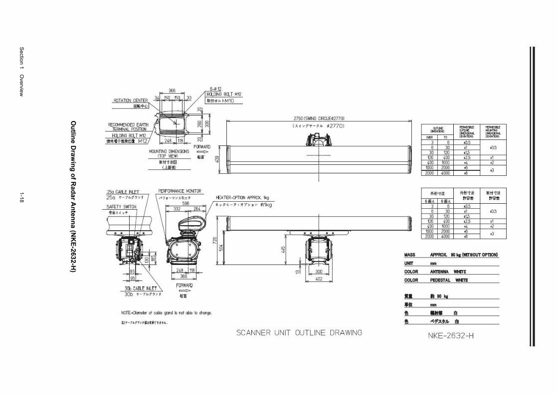
Section 1 O
verview
1-18
Ou
tline D
rawin
g o
f Rad
ar An
tenn
a (NK
E-2632-H
)
RECCM~&.IlED EA'ffii TE~NAL RlSillCN HU.OING OOL T t-112
~"ltHII M12 t<il' FcmtARO =-
2750!S~1NG CIRCLE02770l
<"P"'..,_ ?1• n770J
MOJNTlNll DMENSICNS !TCP VIEW! lfl#"til00
Ll.ooll}
~8 ?JI --+--
FOOW/>i!J =M1!i
NOTE ol:taoo1et d colja giJ'd ~ I'd dlle lo ch:lngo.
llT-1.t.?'7liFIU(ift ! tl.,
I£ATBl ·CPTICN .IJ'ffilX. f, .,;)'t.-,. . ~7¥ 3 !1' Wlkg
iii ~
1:11
402 -
SCANNER UNIT OUTLINE DRAWING
MASS
UNIT
COLOR
COLOR
•• •~* e e
(ljlt>£ ..,.,.,... ..,...,...
OII!E~ MU>£ """""' ,..,,.,.._ !lK KSDul ..... ro llE\tA"IlliS llE\Ull:NS
3 6 <(1.5 6 3IJ •1 tll.5
3IJ 120 •1.5 120 400 t2.5 .t 400 1000 •4 •2
1000 1000 <6 <3 2000 4000 .a
~'1';1; ~'I'd< llltl'f';l;
HU ua. ~ ~ 3 6 <(1.5 6 3IJ •1 ttl.5
3IJ 110 •1.5 120 400 t2.5 .t 400 1000 •4 •2
1000 2000 <6 •3 2000 4000 .a
AI'PROX. 110 !!1 (WITHOUT OPTION) ... AH!ENHA WHErE
PEDESTAL WHm
II IIO kr ... ... e -<i'~911- a
NKE-2632-H
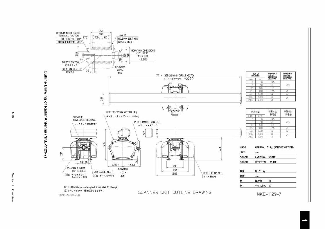
1-19
S
ection 1 Overview
1 2 3 4 5 6 7 8 9
10
11
12
13
14
15
16
17
18
19
20
21
22
23
24
25
26
27
付録
O
utlin
e Draw
ing
of R
adar A
nten
na (N
KE
-1129-7)
RECOMMENDED EARTH TERf-IINAL POSITION
HOLDING BOLT M12 \ 17~11 II E ouu" I c ouu " I lllt!lHlf£~1;1::1! M12
4-f 12 HOLDING BOLT M10 l!i.f;t;f'lv tM10
0 ~~----;fl t MOUNTING DIMENSIONS .,..; 10
FORWARD c:::> !Iilli
ITDP VIEW! l!i.f1"1";!f21
Lliiitl.)
711 ' 225415WINB CIRCLE f22701
r--N
( :<1 /11f ·-7Jv ll227Dl
{l --l --
FLEXIBLE WAVEGUIDE TERMINAL
7 v ~ ~ 7 Jv;J;ll:'lfJ*-T
HEATER, OPTION APPROX. 1kg
;!.,9~-.$1 ':>1"7'~3/ f:l1kg
FffiWARD
PERFORMANCE f-IONITOR J'7:r-7/).~=:9
25a ~-7~''"F lto ? t-1®
30b CABLE INLET c:::> ·- !Iilli
(658)
"' " (Y)
COVER IS OPENED b"-illlilX~
NOTE 'Diorreter of cable <jOI'Id s rot able to cl'cnge. ~)7-7~1,/F~~~~~~~~A.
SCNKE5309-2- \2> SCANNER UNIT OUT LINE DRAWING
MASS
UNIT
COLOR
COLOR
•• Ji!.li):
~
~
CUTU£ PERio15SIIl.E PERMISSillE [)NENSD.IS ClJTLN: lolllJNTNl
DMENSI~AL DlloE~!>IAL
OVER 10 DEVIATO.S DEYIATOIS
3 6 •0.5 5 30 •1 •0.5
30 120 •1.5 120 400 •2.5 t1 400 1000 t4 •2
1000 2000 •6 ±3 2000 4000 •8
~1-lf~"'l";! mt:l-r;t: l!i.f1-tit
U!i~ UT f!i:~ i'ri:~
3 5 •0.5 6 30 ±1 ±0.5
30 120 •1.5 120 400 ±2.5 ±1 400 1000 •4 •2
1000 2000 ±6 •3 2000 4000 •8
APPRO X. 51 kg (WIHOUT OPTION)
mm
ANTENNA WHITE
PEDESTAL WHITE
~ 51 kg
mm
CM$ 8 ~-T.A~JL- 8
NKE-1129-7
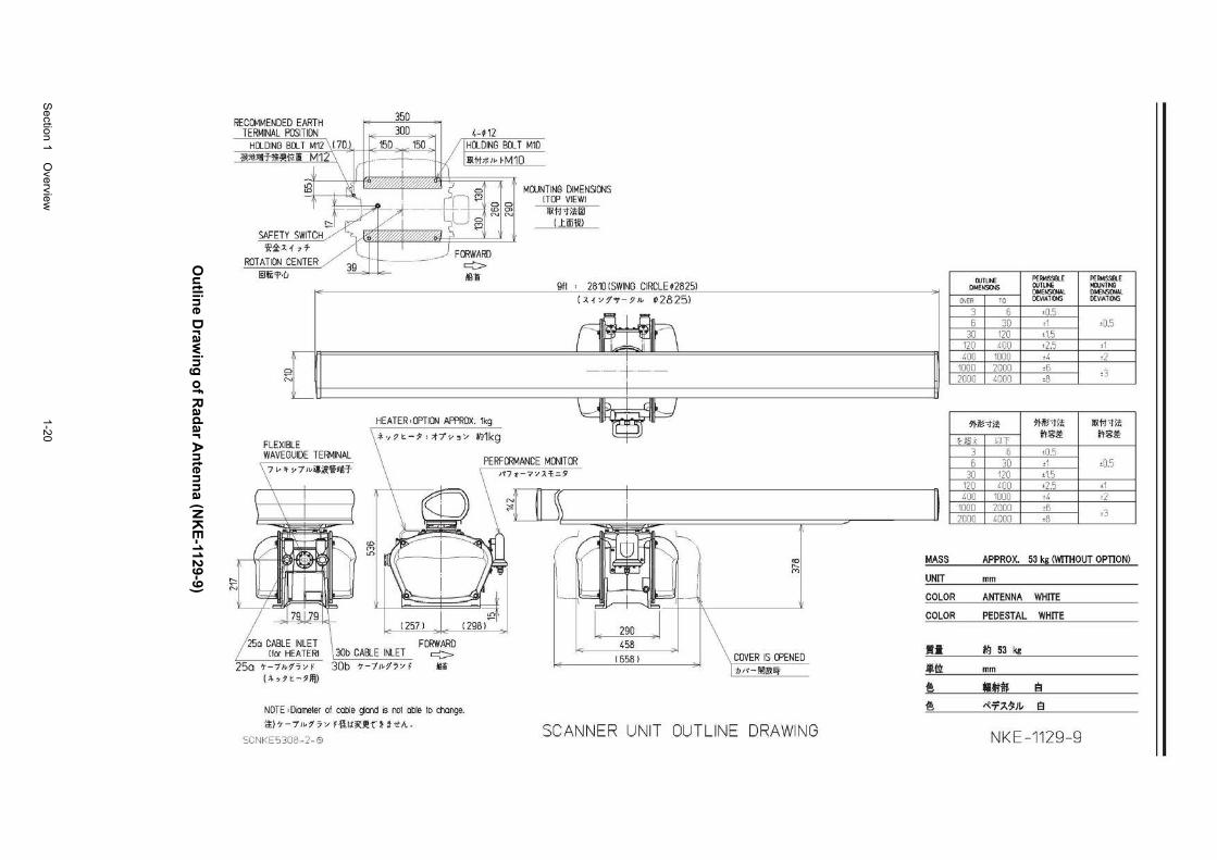
Section 1 O
verview
1-20
Ou
tline D
rawin
g o
f Rad
ar An
tenn
a (NK
E-1129-9)
350 RECOMMENDED EARTH ---
TERMINAL POSITION 300 4-f 12 HOLDING BOLT M12 \ 170 150 150 ki iHDLDING BDL T M10
1f:litliiH-liBH1i tv112 - -r--- - - IJat-J;f,lvl•tv110 -~ \ lr
~I ' ~ a """ t ~I - n 12 aa _I J~ 7 ----+-- "'C> u NN
SAFETY SWITCH~ - (5 -
liNG DIMEN" ONS TOP VIEW! 11Xt-l-t~f2!
Ltiiit!l
V~Af>7- ~ RCT AT ION CENTER
39 - - ·--
@]~'""' Mil!' 9fl 2810 I SWING CIRCLE ,2825l
(J.f'-':1't-9Jv ~2825)
fll --t-- ~ FLEXIBLE WAVEGUIDE TEiiMINAL
HEATER•OPTION Aff'RCX. 1kg
*''~-,.~7~3'-' ~1kg
FORWARD c::::>
PERFCRMANCE MONITOR ,.7~ 7:1::<.'1:=9
25a 'T-/Jv'/7:1 f 30b 'T-7Jv'/7'/ f Mi (-1-,?t-9)!j)
I 558 l
"" " ""'
COVER IS CPENED IJ '•- IIIJ:ili{l>f
NOTE 'Dllrreter of cable garod is not able to ctYJnge. :±)'T-7":17'-' Hlt~:ll'J!t"! i-tt A.
SCNKE5308 -2- <2> SCANNER UNIT OUTLINE DRAWING
MASS
UNIT
COLOR
COLOR
•• .11!.!2
~
~
ClJTLt.E PER>11SSlllE PEIIMSSilE DINENSCNS OOTLN: ~tl.tHNl
DNENSICNAL DIIE:NSICNAL MR TO DEYIATOIS DEY~ lOIS
3 6 •05 6 30 !1 •05
30 120 •1.5 120 400 •25 ±1 400 1000 •4 •2
1000 2000 · 6 ·3 2000 4000 ·8
:91-~'t~ ~~~'tit IIXt-1-tit
t .til ~ UT 0'1?6:~ 0'1?6:~
3 6 •05 5 30 '1 ±0.5
30 120 •1.5 120 400 •2.5 ±1 400 1000 ±4 ±2
1000 2000 ±6 •3 2000 4000 •8
APPRO X. 53 kg (WITHOUT OPTION)
mm
ANTENNA WHITE
PEDESTAL WHITE
*9 53 kg
mm
CMti 8 ~-T7.1ZJI- 8
NKE-1129-9
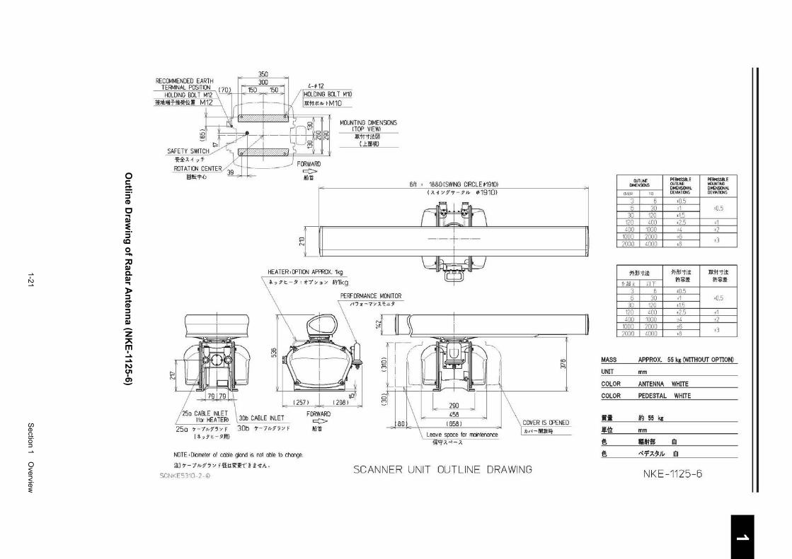
1-21
S
ection 1 Overview
1 2 3 4 5 6 7 8 9
10
11
12
13
14
15
16
17
18
19
20
21
22
23
24
25
26
27
付録
O
utlin
e Draw
ing
of R
adar A
nten
na (N
KE
-1125-6)
RECOMI<IENDED EARTH TERMINAL PDSITICN
HCX.DING BOLT M12 l!IJI!.;fll-t!ll~ii<l M12
SAFETY SWITCH ~~Jd .,'f
ROTATION CENTER @lti;'l'.U
FORWARD c::::> .lill!i
MOUNTING DIMENSICNS !TOP VIEW) l!Xt-1-tl:i;~
Lli!iiW
6ft ' 18BD I SWING CIRCLE ,191m I>. o •1<t- :n• ¢1910>
--+--~l_~--------------~------------~ HEATER,OPTICN APPROX. 1kg
._,,t:-;ll ';>f-7'~3/ 1~1kg
PERFORMANCE MONITOR
..... N
25a ~-~~'' "' ' 30b ~-7•15/F (l,?t-,~
NOTE 'Diarreter of ca~e ~or>d is not able to ch:lrqe.
i±)~-7 ,• 17'-' F~l~ii(J!t' ~ :HtA.
SCNI<E5310- 2- ©
FORWARD c::::> Mill
..... .. ~... ,
Leov e space for maintenance !*'if>."' >,
<0 ..... (Y)
COVER IS CPENED
n" -llllnlllf
SCANNER UNIT OUTLINE DRAWING
MASS
UNIT
COLOR
COLOR
•• .ijt{ii
~
~
OOTLI'oE PEIMSSII..E PERMISSII.E DI~ENSOIS OJTLt-.E MllJNTN3
DIMENSICNAL DI~NSICNAL
OVER TO DEVIAT1£16 DEVIAliCNS
3 6 ±0.5 5 30 •1 •0.5
30 120 •1.5 120 400 ±2.5 ±1 400 1000 ±4 •2
1000 2000 ±6 ±3
2000 4000 •8
?Hfo;otit ?Hii'1l1< IIXt-f'tj:i;
.-.1!1.<. UT Z'l:%:~ !'!-:%:~
3 6 ±0.5 5 30 ±1 ±0.5
30 120 •1.5 120 400 ±2.5 ±1 400 1000 •4 •2
1000 2000 ±6 ±3 2000 4000 •8
APPRO X. 55 kg (WITHOUT OPTION)
mm
ANTENNA WHITE
PEDESTAL WHITE
~ 55 kg
mm
CMM 8 ~-Tl-1111- 8
NKE-1125-6
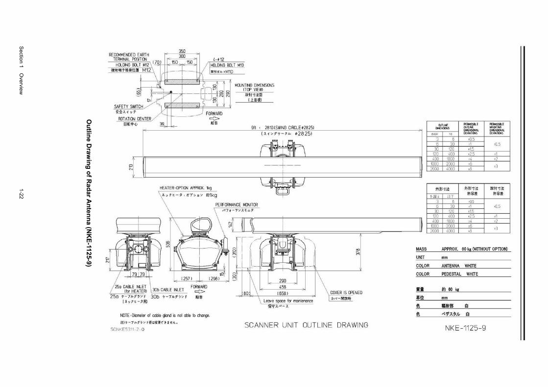
Section 1 O
verview
1-22
O
utlin
e Draw
ing
of R
adar A
nten
na (N
KE
-1125-9)
350 RECOMMENDED EARTH 300
4-•12 TERMINAL POSITION l()_ 15D 150 HOLDING BOLT M12 \ I l v I HOLDING BOLT M10
:Ji:JtHfi-Tii!~iri:l M1L' \ lr
--··-f----. 111!1'1;1m ~M1D
~ ' 0
c{) ~ 8112 0 0
~ ;:5i7 -- uo~· t:: N ~ 12 SAFETY SWITCH _,
~1::>.~ -,7 _j FORWARD ROTATION CENTER 1--- -- - c:::>
IIDfi'l'·u ~ ~..c- ~8
\2 N
HEATER, OPTION APffiOX. 1kg
i , J ~-? ' t7';, 3 '/ A'J1kg
25o CABLE INLET lfor HEATER! \ 30b CABLE INLET
25a 7-71>17 '/ F 30b 7-7"1'7'/ F li·,?t-?!!1)
NOTE 'Diarreter of cable ~aM is nol able to char<;je.
il) 7 -71':17 '/ F~ll!f]!'f ~ <-ttA.
SCNI<E5311- 2- C>
MCXJ~ I
-
TING DIMENSIONS TOP VIEW! ~11'1i;';i0
U.iiiW -
9ft 2810 I SWING CIRCLE •28251 (J.~ '/:f't-?1• ¢28251
--+--
Leave space for moini!Mlonce !*'fA.-.: J.
"' " ""
COVER IS OPENED :/) '<-llllilli:llf
SCANNER UNIT OUTLINE DRAWING
OOTLI'oE PEIMSSIU PERMISSilE DI114ENSOIS OJTLt-.E MllJNTN3
DMENSICHAL DI~NSICNAL
OVER TO DEVIAT1£16 DEVIAliCNS
3 6 ±0.5 5 30 •1 •0.5
30 120 •15 120 400 ±2.5 ±1 400 1000 ±4 •2
1000 2000 ±6 ±3
2000 4000 ·8
?j.Jt:;'fi;'; ~~lli'ii;'; IIX11'1ii';
.-1!1.<. UT Z'l:%:~ !'!-:%:~
3 6 ,o_s 5 30 ±1 ±0.5
30 120 •15 120 400 ±2.5 ±1 400 1000 •4 •2
1000 2000 ±6 ±3
2000 4000 •8
MASS APPRO X. 60 kg (WITHOUT OPTION)
UNIT mm
COLOR ANTENNA WHITE
COLOR PEDESTAL WHITE
•• ~ 60 kg
.l{ii mm
~ CMM 8
~ ~-Tl-1111- 8
NKE-1125-9
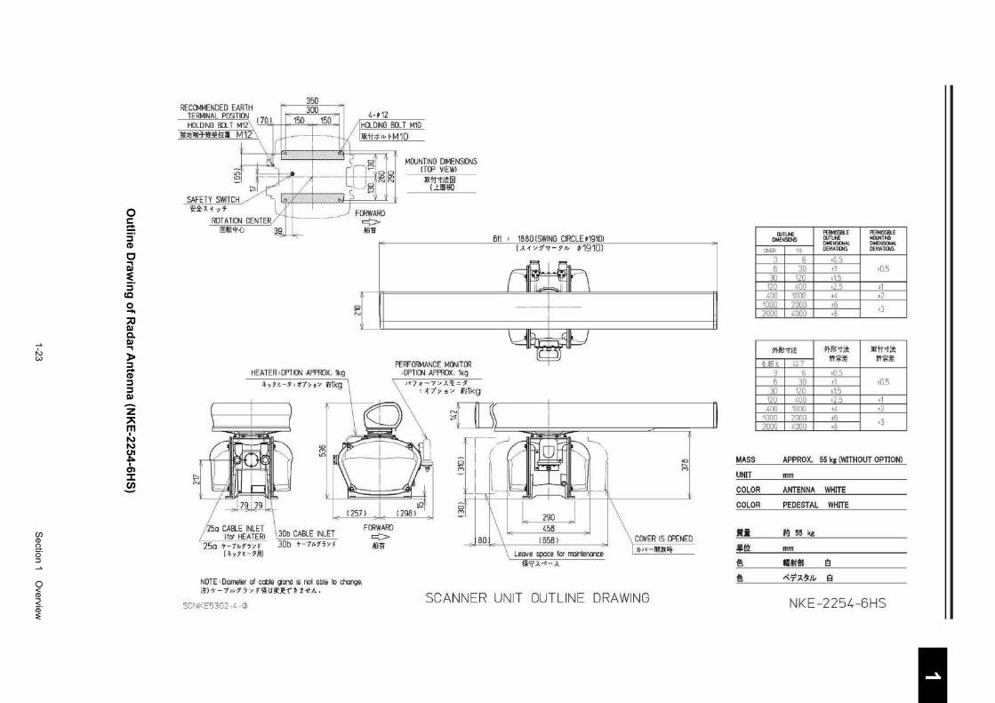
1-23
S
ection 1 Overview
1 2 3 4 5 6 7 8 9
10
11
12
13
14
15
16
17
18
19
20
21
22
23
24
25
26
27
付録
Ou
tline D
rawin
g o
f Rad
ar An
tenn
a (NK
E-2254-6H
S)
RECQ\<IMENDED EARTH TERMINAL PDSITI()IJ HCtDING BU. T M12\ ( 7LYI II< l~l.l , I• I~U ,
l!lit!liH-11t!I!U1:1 M12
SAFETY SWITCH ~~;l.1·yf
RCTATION CENTER IQ)fi'!>;J 3
HEATER,QPTION APPRCX. 1kg ,,,.-,,~7~3~ ~1kg
'25o CABLE INLET lfor HEATER!
25a t-7•15•f (.,,.-,~
3Db CABLE INLET 30b t-7.,15• F
4-,12 HCtDING Bet T M10 ~tl;ti•I· M10
FORWARD c:::> Ail a
MOUNTING DIMENSIOOS ITOP VIEW) ~tl'tit~
U.iliHJ!l
611 ' 1880 I SWING CIRCLE~1910l (;!.1Y?'<t-9J• ~1910)
{ tt=======~~~
FORWARD c::> >Iilli
PERFORMANCE MONITOR 'OPTION AFf'ROX. 1kg Jt7;t~7~A=t.=9
'ot"/'y • " ~~1kg
Leave space for rrointerarce 1*9;<.....:-;_
<0
" (Y)
COVER IS OPENED :tJ'<-JIIl;lj;~
NOTE 'Domeier of cable ~Cll\d 1s rot able to change. 2)t-7~15YF·~~~~~f·A·
SCANNER UNIT OUTLINE DRAWING SCNKE5302- 4- (l)
MASS
UNIT
COLOR
COLOR
•• .11!.12
f! f!
llJTLt\E PERMISSIII.E PERMISSB.E Dt.4ENS()JS ClJTLN: Mll.JNTNl
DMENSICNAL Dllo'ENSICNAL OVER TO DEV1ATICNS DEYIATICNS
3 6 t0.5 5 30 ·1 t0.5
30 120 t1.5 120 400 t2.5 t1 400 1000 t4 •2
1000 2000 t6 ±3
2000 4000 t8
5H~-tit J>Ht!l"fil< I!Xtt"fil<
U iLi. r!T ff~~ .,.~~
3 6 ±0.5 6 30 ±1 !0.5
30 120 ±1.5 120 400 •2.5 •1 400 1000 !4 ±2
1000 2000 ;6 ;3
2000 4000 •8
APPRO X. 55 kg <WITHOUT OPTION)
mm
ANTENNA WHITE
PEDESTAL WHITE
*!! 55 kg
mm
-~$ e ~-T.A~Iv e
NKE-2254-BHS
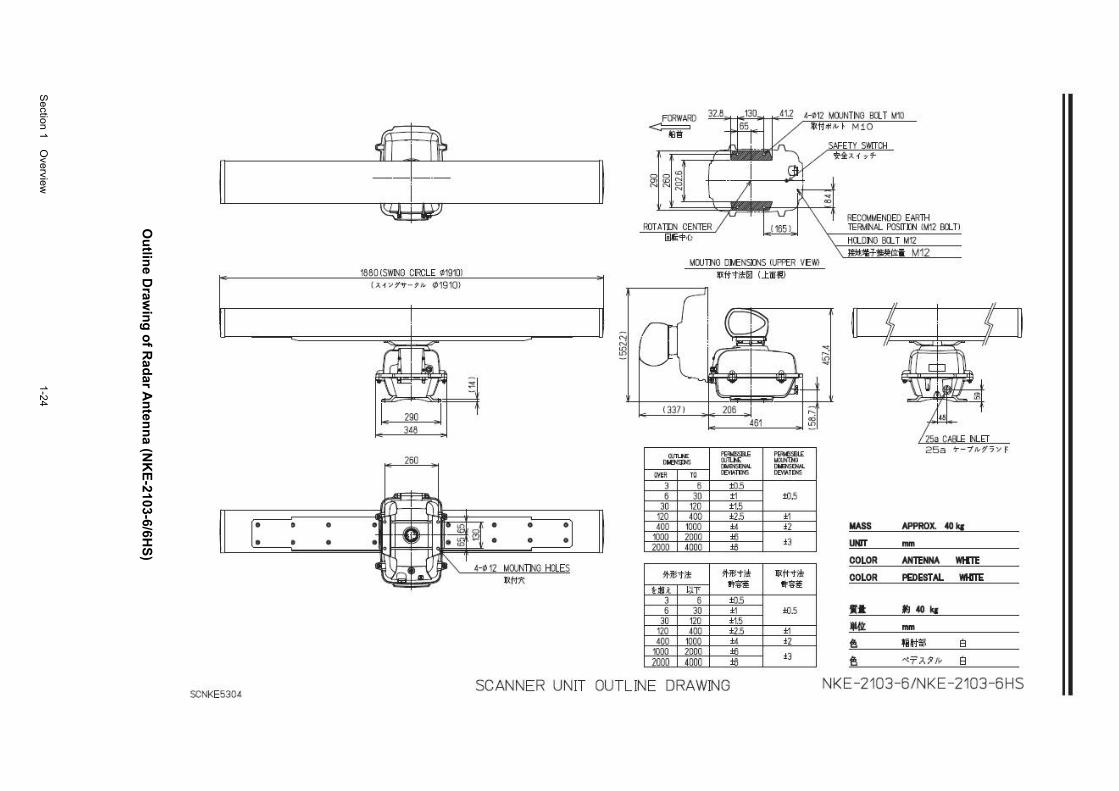
Section 1 O
verview
1-24
Ou
tline D
rawin
g o
f Rad
ar An
tenn
a (NK
E-2103-6/6H
S)
II
• • • •
SCNKE5304
1880 !SWING CFlCLE ~!9'kll {). .f .... ?'"T-?111 01910>
T
~ ~J I, 290 ,II t
3~8
2'60
• • • •
MfiJNTm H!JLES J~f'j/(
l "I til
FOOWAilO
~
~~~~ ~ N
liOT ATDI CEI>ITER lillii<f>•C>
H12 MfiJNTING BCl T M'kl lf{tf""" f M10
RECOUIIENOEO EARlH TE~IINAL POSITJ:N IM12 llO..Tl HQOI'IO OCL T M12 Jilii.~'Jt!!~ M12
MfiJTI'<O OI.ENSil'IS ll.I'PER VEWl 11Xfttill0 (l:i!il!!l
~I o::;;;;:
""""' ~F ,....,. ... '""""' """"" '"'""""' -OVER 10 "'"""' C£V"UNS
3 6 10.5 6 30 t1 10.5
30 120 t 1.5 120 ~DO t2.5 ±1 ~00 1000 .. i2 MASS APPROX. >40 g
101)() 2000 i6 i3 2000 ~000 i6 lHT ....
COLOR AN'IENNA WillE lt-11'1 >1< ~"'i!! l!Xft"'i!!
Ul t VJr ltft tl'iiili COLOR PEDESTAL WI!!!E
3 6 10.5 6 30 ±1 10.5 •• JJ>!Oka
30 120 ±1.5 120 dOO ±2.5 ±1 *Ill: .... <00 1000 .. i2
mo 2000 i6 i3 2001) dOOO i6
t. lilffll e & --<7'?.1 11/ e
SCANNER UNIT OUTLINE DRAWING NKE-2103 -6/NKE-2103- BHS
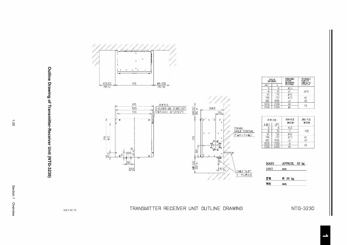
1-25
S
ection 1 Overview
1 2 3 4 5 6 7 8 9
10
11
12
13
14
15
16
17
18
19
20
21
22
23
24
25
26
27
付録
O
utlin
e Draw
ing
of Tran
smitter-R
eceiver Un
it (NT
G-3230)
~//J/~1~ L . 'd
_ MN 250 __ 615 __ MN 250 _ 250 ~ll 250 111
OJTUNE PERMISSBI...E PERt.!JSSB...E DMENS/ONS llJTLNE MllJNTNO
DJUENSI.J'IAL DIMENSIJ,'Al 0'/ER TO IEVL'.TD1S DEVJI.TOOS
3 6 +0.5 6 30 +1 ±05
30 120 +1.5 120 400 +2.5 +1 400 1000 ±4 ±2
615 4-11115.5 585 A H()_DNG BOLTS M12 I 1/2'1 549 J!l:ii;J(Iv f M1211/2')
I ~~~ 6~ :::>N
1000 2000 +5 ±3
2000 4000 ±8
• • ?1-!13-ti* ?1-!13-ti* l!x:f-t-ti* ,----" Ui ~JT
If~~ If~~
COAXIAL 3 6 +0.5 CABLE TERMNAL 6 30 ±1 ±0.5
lD iD
D r-..,.
[0]~7-/lt-!IIT-lD iD
30 120 +1.5 120 400 +2.5 +1 400 1000 +4 +2
I~ r-• .~c-F1~ e
•
1000 2000 ±6 ±3 2000 4000 ±8
J J ~
~lti t:k \ MASS APPROX. 33 kg ;;;;~
UNIT ::!;'N mm CABLE N__ET 7-7'Jc-jf]\O
fll: 11 33 kg
llt{)'L mm
SC~HG5176 TRANSMITTER RECEIVER UNIT OUTLINE DRAWING NTG-3230
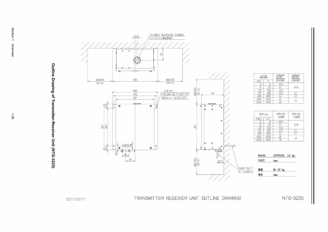
Section 1 O
verview
1-26
O
utlin
e Draw
ing
of Tran
smitter-R
eceiver Un
it (NT
G-3225)
FLEXIBLE WAVEGUIDE TERMINAL 7 v '< "71c~iS<~>liH-
%///~...,L/ /" A I / F / r:,---L,---L-~ ~
/
MIN 250 450 MIN 250 250 tJl 250 tJl
450 -~~ H15.5 430 lfiHOLDING BOLTS M12 11/2'1
IE 391 ~I
llXit;J<Iv I• M1211/2"l
~b 0 0 "'I-
~ 0 ao ("")
I ~ t-fo ~~~ 0 0 i _IN 0
~ t ~ 0L
/ / / / I OJTLI'£ ~w~~BLE I ~~~~E DNENSD.JS DMENSDJAL DMENSKJ.JAL
OVER TO ll::VIATrnS DEVJATKJ.JS
3 6 +0.5 5 30 ±1 ±0.5
iii I d r:: I 30 120 +15 ~ ~ nz / I 120 4oo t:i 5 ±1 2 ~ I '
0 400 1000 ±4 ±2 1000 2000 ±6 ±3 2000 4000 ±8 : ?:9 e~ ~
7'Hf~'1i! 7'~-~:r$ I llX!i;!$ Hil i J:;T it"'~ it"'~
~ ~ 3 6 +05 6 30 ±1 ±OS
~I I I 3o 120 +1.5 120 400 ±2 .5 ±1
~ / 400 1000 ±4 ±2 1000 2000 +6 ±3 2000 4000 ±8
~ \ MA" AP>'ROX. >0 k< ~~ ;! Ek \ UNIT mm ;;;~ 2 ~
j:: CABLE INLET f{jl: *9 15 kg
~ 7-7/c~}..D
lli{l): mm
/
SCNTG5177 TRANSM ITTER RECEIVER UNIT OUTLINE DRAWING NTG -322 5
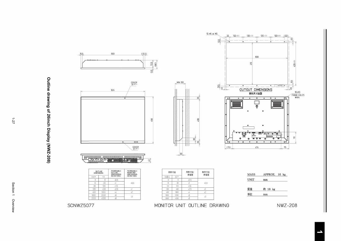
1-27
S
ection 1 Overview
1 2 3 4 5 6 7 8 9
10
11
12
13
14
15
16
17
18
19
20
21
22
23
24
25
26
27
付録
O
utlin
e draw
ing
of 26in
ch D
ispla
y (NW
Z-208)
Jp.p_ 593
l,..---~.
--.
OUTLINE PERMISSIBLE DIMENSIONS OUTLINE
DIMENSIONAL
OVER TO DEVIATIONS
3 B ±0.5
B 30 ±1
30 120 ±1.5
120 400 ±2.5
400 1000 ±4
1000 2000 ±6
2000 4000 ±8
SCNWZ5077
..
"'
I
COVER tJ;~-
...
PE~ISSIBLE MOUNTING DIMENSIONAL DEVIATIONS
±0.5
±1 ±2
±3
(J2,5l
~I ~1 ~1 L{)
(':!
~
<0 L{) ...,.
71-~"1)!
U:l.~ fH 6
30
30 120
120 400
400 1000
1000 2000
2000 4000
71-~"1)! WI'-~~
±0.5 ±1
±1.5
±2.5 ±4 ±6
±8
<0 0 ...,.
10-~6 or M5
llllti"1i! m-~~ I
I ±0.5
±1 ±2
±3
0 ...,.
600
~~·- -~rouro-fMENSION~ ..... A
:Qll.#1i::<tii!E oo . 0 . 0 . 0 . . . 1r•:1 D r•:~ .
00 ell!!!!!!!!!!!!!e • ell!!!!!!!!!!!!!e . . . . . . . .
c==J . . . . . v--
... m·· ~ = 1- .
0 0 11!1 g 11!1 0 g 11!1 '\ oo . 0 . 0 . 0 . oo
-{ 75) - 474 - 75 _I
MASS APPROX. 16 kg
UNIT mm
WI: ~ 16 kg
lji{JL: mm
0) N ...,.
10-¢6 OLES
Jl)(
~[
MONITOR UNIT OUTLINE DRAWING NWZ-208
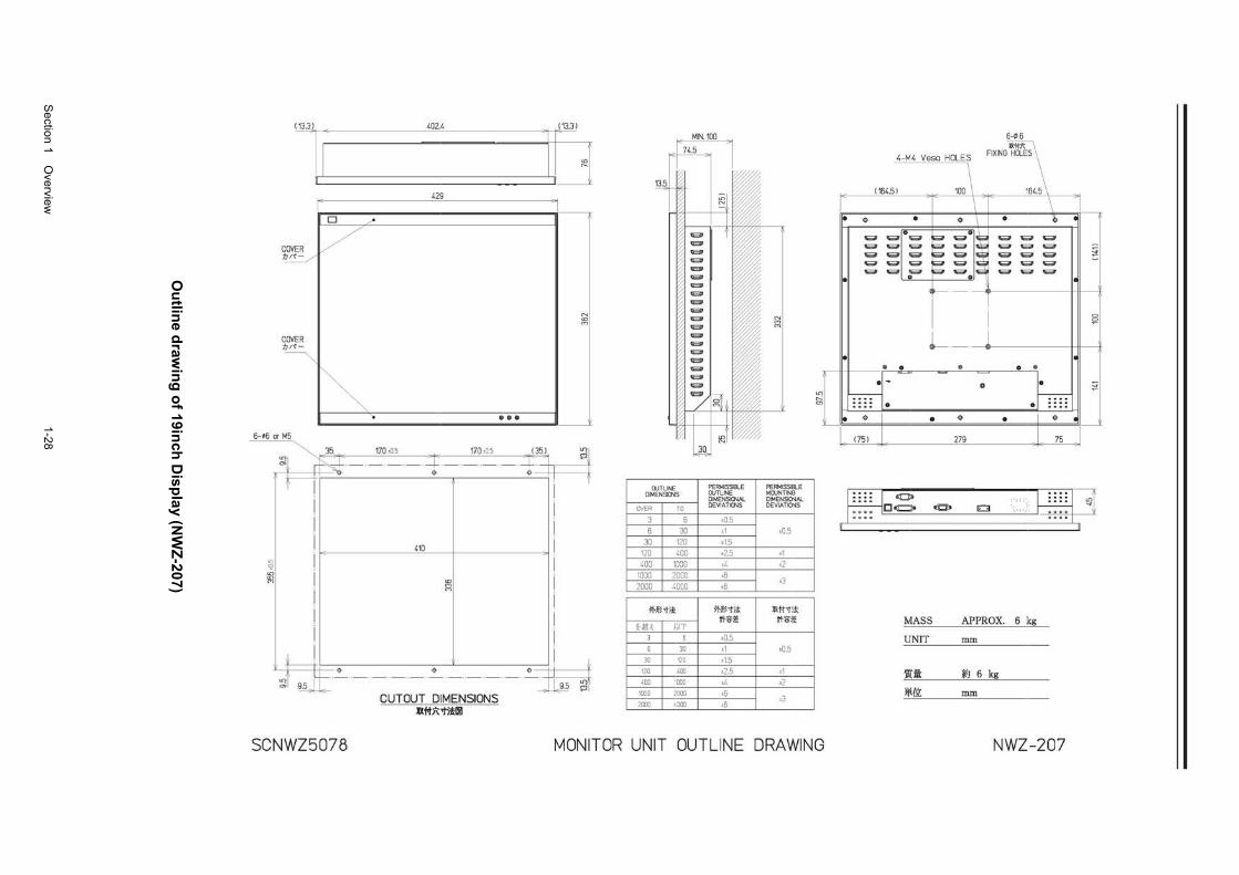
Section 1 O
verview
1-28
O
utlin
e draw
ing
of 19in
ch D
ispla
y (NW
Z-207)
l 402.4
'113 42!l
l r D ""
-1
l/
N <0 (T)
I"", • ••• 6-;6 or M5
LD LD (T)
i ,35 170>05 170>05 i~. ~~ r+~:X----:X---- .. -~~ . .
410
to (T) (T)
f----ll=~ ____ L ____ ~Jt ) ~'~'d~ ~
CUTOUT DIMENSIONS ll#l\"i"i!l!l
OUTLINE DIMENSIONS
~~ 6
30 30 120
120 400
400 1000 1000 2000
2000 4000
*~'tit<
Ui. I !n-6
30 30 120
120 400 400 '000
1000 ;•ooo 2000 1000
PERMISSIBLE OUTLINE DIMENSIONAL DEVIATIONS
>0.5
±1 ±1.5
±2.5 ±4 ±6
±8
*~'tit< I ~:li':~
±0.5 ±1 ±1.5
±2.5 ±4
±6 ±8
N (T) (T)
PERMISSIBLE MOUNTING DIMENSIO'JAL DEVIATIO'JS
±0.5
±1 ±2
±3
]jXt-J-J-:~ ~:li':!~
±05
±1 ±2
±3
,__ en
SCNWZ5078 MONITOR UNIT OUTLINE DRAWING
6-¢6
'--,- . .................. ' ''-''-'--~
··-··-· 100 -··-
\ • • • • \ • • • ~ ~u~ ~ ~· ! ~ ""'"' ~ ~ ~ ·~ ~~ ~ ""'"' ~ ._.,. ~ ~ ·~ ~~ ~ ,...., ~ ~ ~ ·~ ~~ ~ ""'"' ~ ~ ~ ·~ ~~ ~ ,...., ~
• Cl D
~-
I
I I
D D
L _ __J__ •
" • " • @ . ~ 0 • ._.,.
'-:-:-;-:- f---:-:-:-:-• •
• • • • • • • I_ (751 __ 279 -- 75 _I
g~ ..... ~·B =g===v ~~ i) ~ 0 " ' :. 0000
0000
MASS
UNIT
It :I J¥t{.\L
APPROX. 6 kg
mm
*1 6 kg
mm
NWZ-207
I
\
I
\
I
\
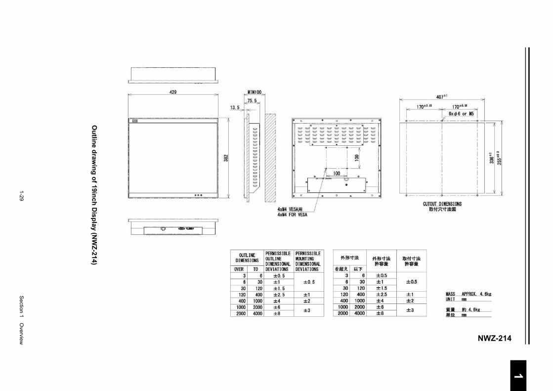
1-29
S
ection 1 Overview
1 2 3 4 5 6 7 8 9
10
11
12
13
14
15
16
17
18
19
20
21
22
23
24
25
26
27
付録
Ou
tline d
rawin
g o
f 19inch
Disp
lay (N
WZ
-214)
NWZ-214
I. ... . MIN100
13.5
liiiil
~
h . : ::~ d OUTLINE
DIMENSIONS
OVER TO 3 6 6 30
30 120 120 400 400 1000
1000 2000 2000 4000
4xM4 VESA,Il! 4xM4 FOR VESA
PERM ISS I BLE PERMISSIBLE OUTLINE MOUNTING DIMENSIONAL DIMENSIONAL DEVIATIONS DEVIATIONS
±0. 5 ±1 ±0.5 ±1. 5 ±2. 5 ±1 ±4 ±2 ±6
±3 ±8
11-~-.t~
~mit J<.l"'F 3 6 6 30
30 120 120 400 400 1000
1000 2000 2000 4000
;;---o
11-~-t~ ff~ii:
±0.5 ±1 ±1.5 ±2.5 ±4 ±6 ±8
407±1 ·- .
1· r_!1, .... 170±0.15
'l' 6xck6 or MS"'I 1 ---- ---4>
I I
I I
I I
I I
I I
I I
l <I
il)lf.t;f'~ ff~ii:
±0.5
±1 ±2
±3
I
I ! f
I I I I
I I I I
't, ~ I I I I M LO
I "' :g I
I I
I I I
I I I
j :dl- I l - -.-- ----..
CUTOUT DIMENSIONS ll)l#R-t~lll
MASS APPROX 4 6kg UNIT mn
•• *3 4 6kg .11!.{;1 mn
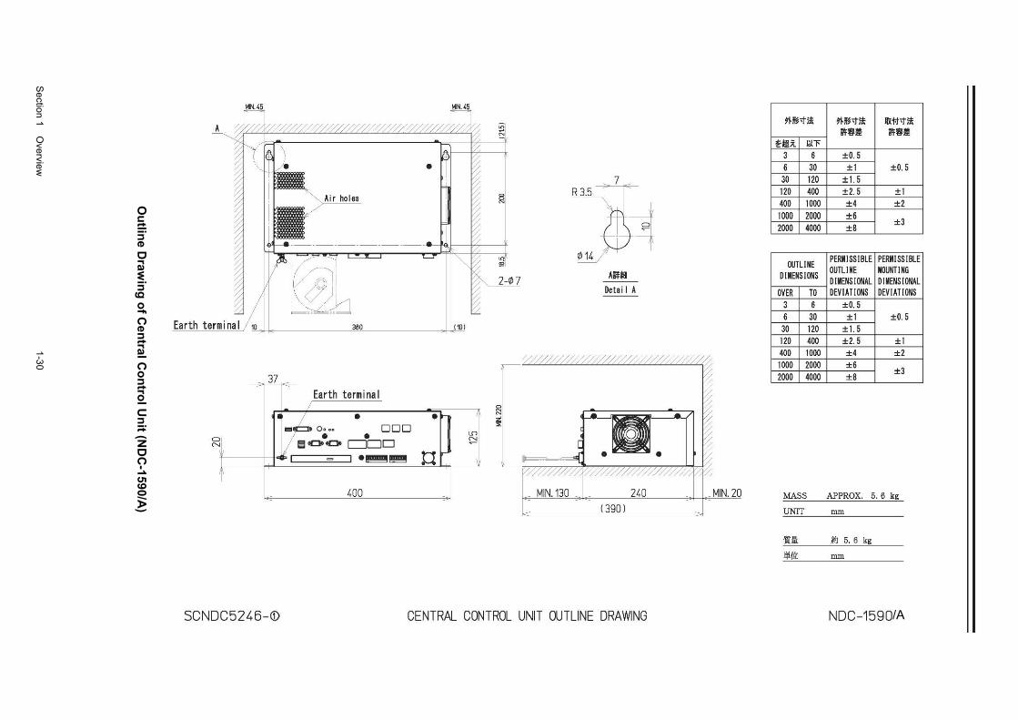
Section 1 O
verview
1-30
Ou
tline D
rawin
g o
f Cen
tral Co
ntro
l Un
it (ND
C-1590/A
)
/A
a N
- 37 Earth terminal
_L_
l~ . • • Oooo ODD • • Iii c::::. c::::. c:::::::r:::JD
tl ;= I = I•~~
I
lc 400 J
lD ~
__j
~ ~
7
i-7~ Alf*B
Detai I A
////////////////////////////////~
L_~~ ~~~~~~~~~~
MIN.130 240 (390)
SCNOC5246-G:> CENTRAL CONTROL UNIT OUTLINE DRAWING
MIN.20
~~-:tit ~~-:tit lllH-t':f'it M:fi.Jf M:fi.Jf
~-it l;t"F
3 6 ±0.5 6 30 ±1 ±0.5 30 120 ±1. 5 120 400 ±2.5 ±1 400 1000 ±4 ±2 1000 2000 ±6
±3 2000 4000 ±8
OUTLI NE PERMISSIBLE PERMISSIBLE
DIMENSIONS OUTLINE MOUNTING DIMENSIONAL DIMENSIONAL
OVER TO DEVIATIONS DEVIATIONS 3 6 +0.5 6 30 ±1 ±0.5 30 120 ±1.5 120 400 ±2.5 ±1 400 1000 ±4 ±2 1000 2000 ±6
±3 2000 4000 ±8
MASS APPROX. 5. 6 kg
UNIT mm
'Ita ~ s. 6 kg
lliilt mm
NOC-1590
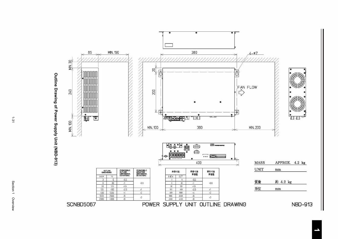
1-31
S
ection 1 Overview
1 2 3 4 5 6 7 8 9
10
11
12
13
14
15
16
17
18
19
20
21
22
23
24
25
26
27
付録
Ou
tline D
rawin
g o
f Po
wer S
up
ply U
nit (N
BD
-913)
85 MIN.150
C) ..... N
C)
~ :Z ~
~~~~~m~~ l~m~m~~ ~~m~m~~ ~~m~mm ~~mm~m ~~mm~m •
SCNBD5067
WTUNE DMEN51~
OVER TO
3 6 6 30
30 120 120 400 400 1000
1000 2000 2000 4000
/
PEffi/IISSIII..E OJTLINE Dt-ENSCl'W. DEVIA11CNS
•0.5 •1 ±1.5
±2.5 •4 •6 •8
l~ . J • •
~I II I
t@~
rl¢ FLOW ~~
• I I
•
•
•
~~ /
~~ •
MIN.100 360 MIN. 200
/
11£~·1·1 ~ I8±BJ G!iiiiD-- .1 ••• ~ ®
__J-o- ~l!l!!l!ll!i • = !O@Eririril • I 400 ____J MASS APPROX. 4.2 kg
PEFfiotiSSB..E t.UlJNTINB M-~~ M-~'t-i* .X f.! 'I''* UNIT mm llMENSKN.tl. IEVIATICNS l't!il~ l't!il~
HiLi. ~JT
±0.5
3 0 •0.5 0 30 ,, :t-0.5 1t:it ~ 4.2 kg
±1 30 120 t1.5
110 '00 ±2.5 ±1 lji{ft mm •2 ,00 mo •4 •2
•3 1000 2000 •6 2000 ' 000 •B
•3
POWER SUPPLY UNIT OUTLINE DRAWING NBD-913
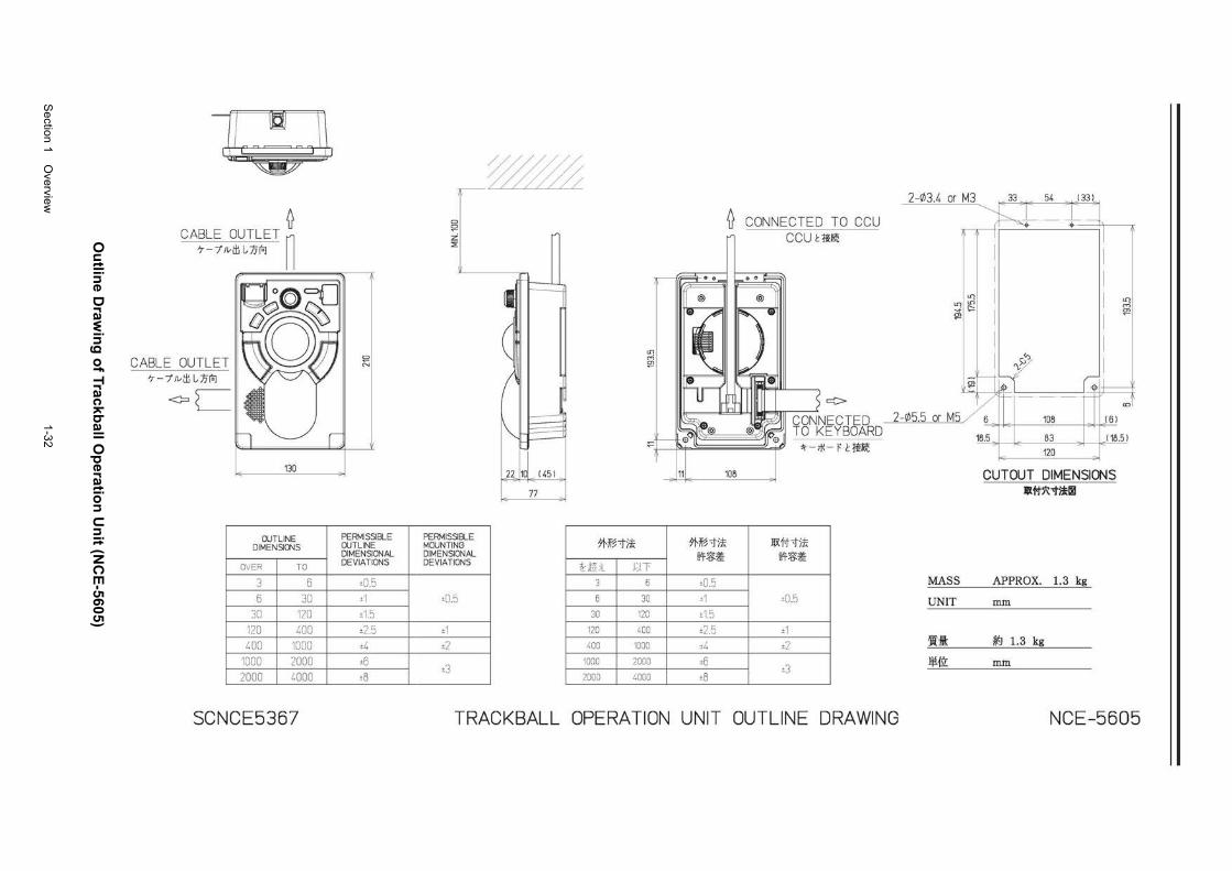
Section 1 O
verview
1-32
Ou
tline D
rawin
g o
f Trackball O
peratio
n U
nit (N
CE
-5605)
~ CABLE OUTLET ~
7-/Jvtll L,)J['o] II
CABLE OUTLET 7-/Jvtll L,)J['o]
<=C
130
OUTLINE DIMENSIONS
OVER TO
3 6 6 30
30 120
120 400 400 1000
1000 2000 2000 4000
SCNCE5367
CJ
N
PERMISSIBLE OUTLINE DIMENSIONAL DEVIATIONS
±0.5 ±1
±15
±2.5 ±4 ±6 ±8
CJ !;2 :z' :E
PERMISSIBLE MOUNTING DIMENSIONAL DEVIATIONS
±0.5
±1 ±2
±3
n" 1101 c 1 45 1
77
LD
g
*Jig 'f)! ~tii .UT
3 6
6 30
30 120
120 400
400 1000
1000 2000
2000 4000
0 CONNECTED TO CCU CCUI:itlri'C
c:::>
:1'-iJ'-rctm
108
*Jig 'f)! ]jX1i"1l! WI'~~ WI'~~
±0.5 ±1 ±0.5 ±15
±2.5 ±1 ±4 ±2 ±6 ±8
±3
2-03.4 or M3 33 54 I 331
~~ T T :J ~+-+
I
I
I
LD I LD
Lr1~ g "'-I
~
I
I SJ""
'\:
~u ~
-1----------1
rr-~- i 2-05.5 or M5 X <DI
161
18.5 83 I 18.51
120 ~
CUTOUT DIMENSIONS lllt:#5\~~
MASS APPROX. 1.3 kg
UNIT mm
W::i: ~J 1.3 kg
.lj;!.{ft mm
TRACKBALL OPERATION UNIT OUTLINE ORA WING NCE-5605
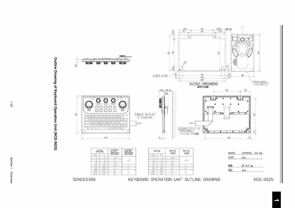
1-33
S
ection 1 Overview
1 2 3 4 5 6 7 8 9
10
11
12
13
14
15
16
17
18
19
20
21
22
23
24
25
26
27
付録
Ou
tline D
rawin
g o
f Ke
ybo
ard O
peratio
n U
nit (N
CE
-5625)
en ~
81 ~ '"
ell ~r iT i 72 '1 vr:.;":>
C)
N
270
OUTLINE DIMENSIONS
OVER TO
3 6
6 30 30 120
120 400 400 1000
1000 2000
2000 4000
SCNCE5368
PERMISSIBLE OUTLINE DIMENSIONAL DEVIATIONS
±0.5 ±1
±1.5
±2.5 ±4 ±6
±8
4-05.5 or M5
CABLE OUTLET 7-/lv/lllnlo:i
~¢>
Jl PERMISSIBLE MOUNTING *~-tl! DIMENSIONAL DEVIATIONS 1-El:t ~H
6
±0.5 30
30 120
±1 120 400
±2 400 1000
±3 1000 2000
2000 4000
*~-tit< a'f?ii:~
±0.5 ±1
±1.5
±2.5 ±4 ±6
±8
220 248 260
CUTOUT DIMENSIONS lR.#:i\:"'l"i*~
<::=o
CONNECTED TO TRACKBALL
I, 7 "Y :7 ;t: -Jv Ht~
JV(j;J"-t)!
a'f?ii:~
±0 5
±1 ±2
t3
19
KEYBOARD OPERATION UNIT OUTLINE DRAWING
152
$ $
$
$ 19
19
248
$
C)
N
TRACKBALL I, 7 ·y 7>t:-Jv
('..
""
MASS APPROX. 0.8 kg
UNIT mm
fill: ~ 0.8 kg
lji{ll: mm
NCE-5625
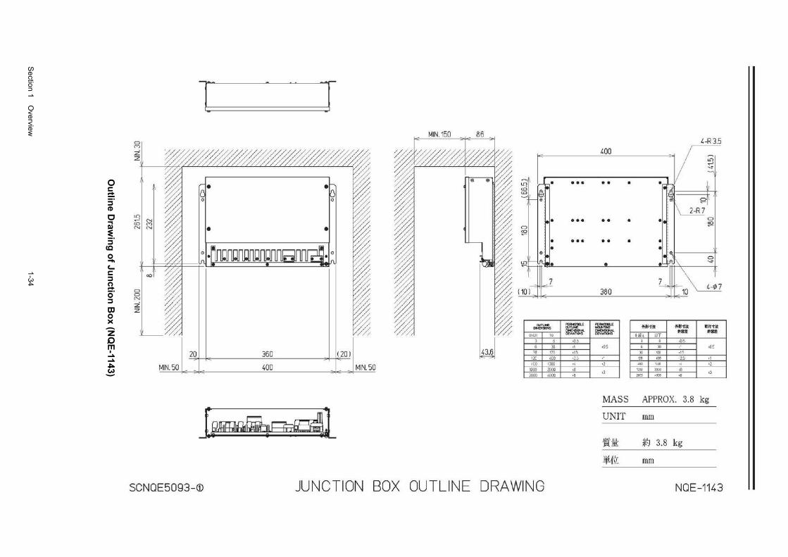
Section 1 O
verview
1-34
Ou
tline D
rawin
g o
f Jun
ction
Bo
x (NQ
E-1143)
Cl (Y)
:Z z
~I N <D (TJ N N
Cl Cl N
:Z z
a:J
20
MIN. 50
T - T MIN. 150 86
360 (201
400 MIN. 50
~~d
4-R 3.5 400 I - -- - I
- - I LD I .....-' I __,.
I - , . I
- I I l.!1 ,.--~• •••••• • h ~~·
~ 4}, I !~ ~r · ~e = \___1£1 . . .. . . . . ~
0 ~
~ • ••• •• • • • • I '
$ ,
'.a t= ~ • • • 1ft\\ S' \ '
\ 7 7
(1o C ~~---'- 38o ~ ~1o ~
WTUE PEI>ISSB.E ""''""' Jt.r>~ll Jt.l>~il: lllff'h'l< . .......,.. WTUfE ...... ,.., OIE~AL OIEN511JiAL IIIII!! liB OE\'IA.TIONS OEVIATICNS t-l!h UT
·0.3 ' G o0.5 JO ,, ·0.5 6 " ~ •DE
~0 170 •15 " "" "\.S 12( 4[0 •2,:) 120 "'' -2.5 ~co [OJ ., •2 <OJ '(OJ ., •2
110J 2(~0 ,, ,J
'COO lOCO ·6 ,, :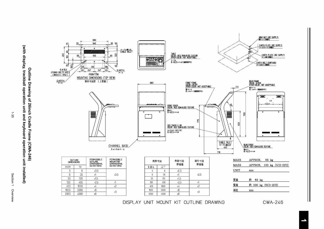
1-35
S
ection 1 Overview
1 2 3 4 5 6 7 8 9
10
11
12
13
14
15
16
17
18
19
20
21
22
23
24
25
26
27
付録
O
utlin
e Draw
ing
of 26in
ch C
radle F
rame (C
WA
-246) (w
ith d
isplay, trackb
all op
eration
un
it and
keyb
oard
op
eration
un
it installed
)
680 Ln 20 640 20 ~ " -----------. . • r 7-7MIJ..:I<: C) CABLE INLET "' ~ C) 8!t • 510 !· r
C)
85 ~
~ i -----------J i ~M" •
" ~~;,;, 1-,J-IJ,,~ 15.5 93 247 l 247 J 93 EARTH
. . ___ S M12 I t - -I ~#If. I~~ M12 I FRO'JT !iJ
MOUNTING DIMENSIONS (TOP VIEWl
7-:A
CHANNEL BASE f"l'>''f-1~"{-J.
OUTLINE PERMISSIBLE PERMISSIBLE DIMENSIONS OUTLINE MOUNTING
DIMENSIONAL DIMENSIONAL
OVER TO DEVIATIONS DEVIATIONS
3 6 ±0.5
6 30 ±1 ±0.5
30 120 ±1.5
120 400 ±2.5 ±1
400 1000 ±4 +2
1000 2000 ±6
2000 4000 ±8 ±3
680
D
--
91-~"1)!
H~i J.Tf 3 6
6 30
30 120
120 400
400 1000
1000 2000
2000 4000
TABLE
5~~ 'ctf~~~6"f'-~E~~f T-1n, ~·N2.5"Y~>i!IUUHI
FRrnT FRAME
5~~ 'eli~~ NOT ACCEPT Ml.E 17~-A ~·~M<-(ftUIH)
blrJ :C~]RSEMI-GLOSS TEXTURE U~<~·N2.5"Y~*
Mar~~f.5IL~~-GLOSS TEXTURE 'tHM-(ti:)(t;) ~·N2.5'w~>ll
91-~"1)! WF-~~
±0.5 ±1
±1.5 ±2.5 ±4
±6 ±8
11X#"1ii WF-~~
±0.5
±1 ±2
±3
718
·--.......··--......... / --....... .. '-....../.
~
MASS
MASS
UNIT
Wi: Wi: lli{ll:
Wr~1t=fi~~ NOT ACCEPT AB..E !l7~-A ~' >M<-(ftUIH)
D
~
§
--!J"OL1{:~~~ SEMI-GLOSS TEXTURE fb~<~·N2.511Y~>I!
APPROX. 65 kg
APPROX. 100 kg (NCD-2272)
mm
~ 65 kg
~ 100 kg (NCD-2272)
mm
DISPLAY UNIT MOUNT KIT OUTLINE DRAWING CWA-246
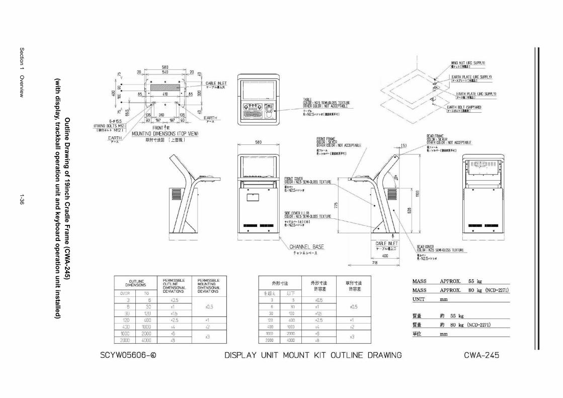
Section 1 O
verview
1-36
Ou
tline D
rawin
g o
f 19inch
Crad
le Fram
e (CW
A-245)
(with
disp
lay, trackball o
peratio
n u
nit an
d ke
ybo
ard o
peratio
n u
nit in
stalled)
580
~ 20 540 20 0
~ v . . . CABLE INLET 0 en 7 /1!.-'I!Al\
)
I D 85 • 410 • 85 ~ "' ~ . - J "' ~A gt ~rr · r·~ t---<0 // ~~C)
"' // / 135 310 135 ", ~ ~/ / 93 197 197 93 " E~~IH
- -- ·s M12 n f ""J-I....1J" L ~A~'"l I
/MOUNTING DIMENSIONS ITOP VIEWI E~~IH 1 IIXfHJ!I!!I I J:.oof! I
L_
OUTLINE PERMISSIBLE PERMISSIBLE DIMENSIONS CUT LINE MOUNTING
DIMENSIONAL DIMENSIONAL
0'/=R TO DEVIATIONS DEVIATIONS
3 6 ±15
6 ~0 ±1 ±O.J
:JU 12U ±1.J
120 ~00 +2.5 +1
4JU 1UUU d, _!_:2
IOOC 2000 +B ±3
2UUU 4[][][] ~3
r==l L_~J
TAiiE
~~~~ . Q _ COLal: NOT ACCEPT,IB_E IJQT!~ lfllH· "'+t- ~~: N2.5 SEMI-GLOSS TEXTU!t
~ ['-L ;~~z5"""*1ti!U:'~<'~I
FRONT FRAME 580 ~~~ 'eft~~ NOT ACCEPT ABLE
IDIJV-ll J'.; ""''- l!tl'<U'I"'I
r-~~=
b~~ :C~~]RSEf.I-{JLOSS TEXTURE liJ:bl~-f':; N2.5"YY*
D ~DE COVER Ill IRI COLOR : N2.5 SEf.I-{JLOSS TEXTURE <tHo,<-l!i'J l:tl -- !!!: N2.5.1\Y~;j;:
~
\\,CHANNEL BASE f~ :;;l,;v--:-.A
1>m·m 5'l'JB-ti! IIXiHi! ~'f?fj:~ ~'f?fj:~
~~;(_ UT 3 I 3 ±0.5
l~ ±I ±0.5
30 120 ±1.:
120 400 +2.5 +1
400 100] l4 lL 1000 2000 +6
~s ±3
2000 4000
",
7-7Joi/i.AD
400
718
WING NUT IJRC SUPPL Yl /Ill+.~ I \til~ I
~-~ ,_ -17-A1t.--~IMI£l /·-"· '--~/ _j EARTH PLATE IJRC SUPPLYI
' . ,j /
// </~"~ EARTH PLATE I.H: SUPPL Yl ~ / /// ~ ~.... ~17_->~ii~l~!f~IE~M.LJ ___ _
'../,/~/
-",
I 5 I
.__'..// >.:.. EARTH BOLT ISHIPY ARDI / / 17-A*J'L.~ [i§Jtjf)
/
_/
"~/
"' N
"'
\ \
0 0
!fAR FRAME Clilll : ~LVER OTHER COLOR : NOT ACCEPT ABLE fl7 o-• !!_; """-i!!l'iH'I"'J
0~ • • ~
. .
--. . __j
\ !fAR COVER \ COLOR : N2.5 SE~-BLOSS TEXTURE fl>"-1'. 'N2.5"»f.
MASS APPRO X. 55 kg
MASS APPRO X. 80 kg (NCD-2271)
UNIT mm
'!tit k0 55 kg
'!tit k0 80 kg (NCD-2271)
!il{lz: mm
SCYW05606-© DISPLAY UNIT MOUNT KIT OUTLINE DRAWING CWA-245
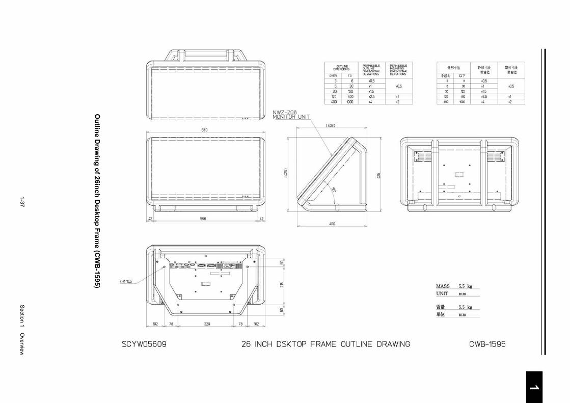
1-37
S
ection 1 Overview
1 2 3 4 5 6 7 8 9
10
11
12
13
14
15
16
17
18
19
20
21
22
23
24
25
26
27
付録
Ou
tline D
rawin
g o
f 26inch
Deskto
p F
rame (C
WB
-1595)
4-¢10.5
#~~ ~=-·-·_·_·_·_·_·_·_·_·_·_
~=·==·==·==·==·==·==·==·==·==· 000 ·~ 680
t;:::: • • ---==--------ooo--
RdJ ~ 1 uF .?2_ 596 .?2_
c:::=•?
rr=:::JJ
NWZ-208 MONITOR UNIT
C) LD
"' N
LD N .....
~ ~-----AF....,"""''-+------l'
E9
102 78 320
.. 78 102
C) <D
OUTLINE DIMENSONS
OVER TO
3 6 6 30
30 120 120 400 400 1000
400
PERMISSBLE OUTLINE DIMENSONAL DEVIATIONS
t0.5 t1 t1.5 t2.5 t4
<D N .....
PERMISSIBLE MOUNTING DIMENSIONAL DEVIATIONS
±0.5
±1 ±2
" lr==·-1 10~ ·~ ~ ~.·~
I I I 0 _
l l ll="---
JT
SCYW05Ei09 26 INCH DSKTOP FRAME OUTLINf~ DRAWING
*~'1)! *~'iii W#'1i!
t-Mli ~n
3 6
6 30
30 120
120 400
400 1000
r------
rr-n lL__[J
~=:::J -·-
MASS 5.5 kg
UNIT mm
f!Ui 5.5 kg
~fll: mm
~:&:~ ~:&:~
±0.5 ±1 ±0.5 ±1.5 ±2.5 ±1 ±4 ±2
~~( IJI
I
I
~
~
CWB-1595
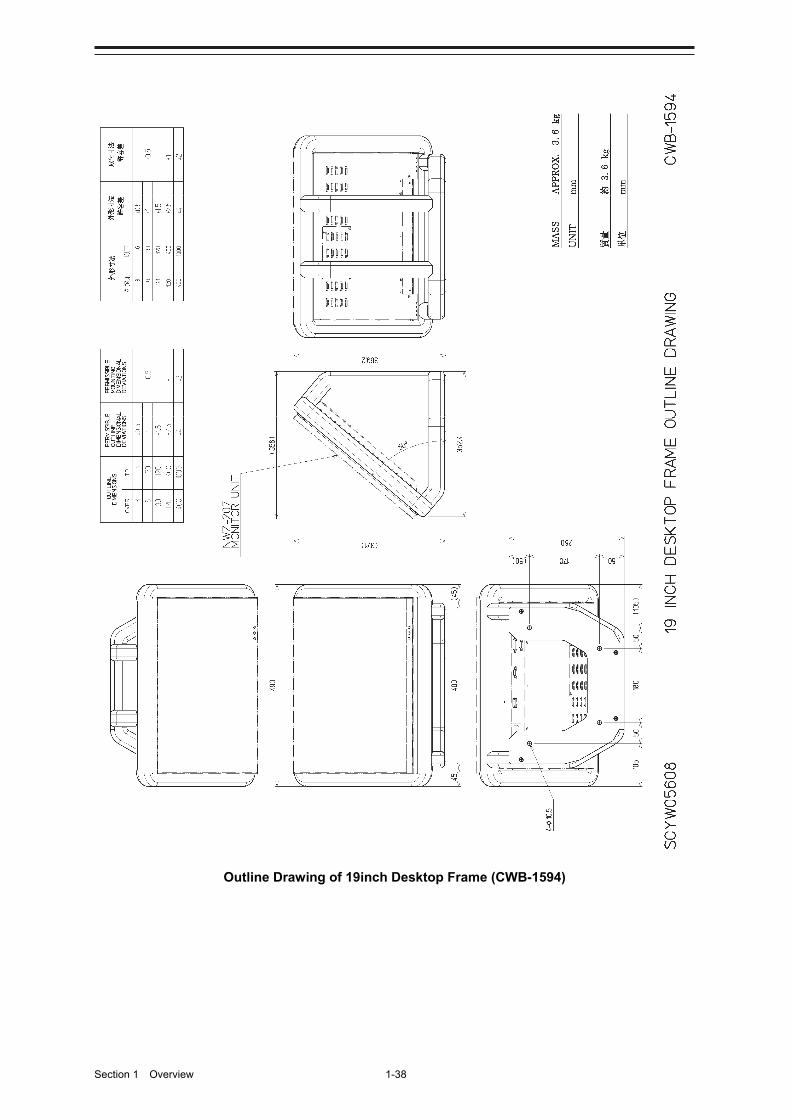
Section 1 Overview 1-38
Outline Drawing of 19inch Desktop Frame (CWB-1594)
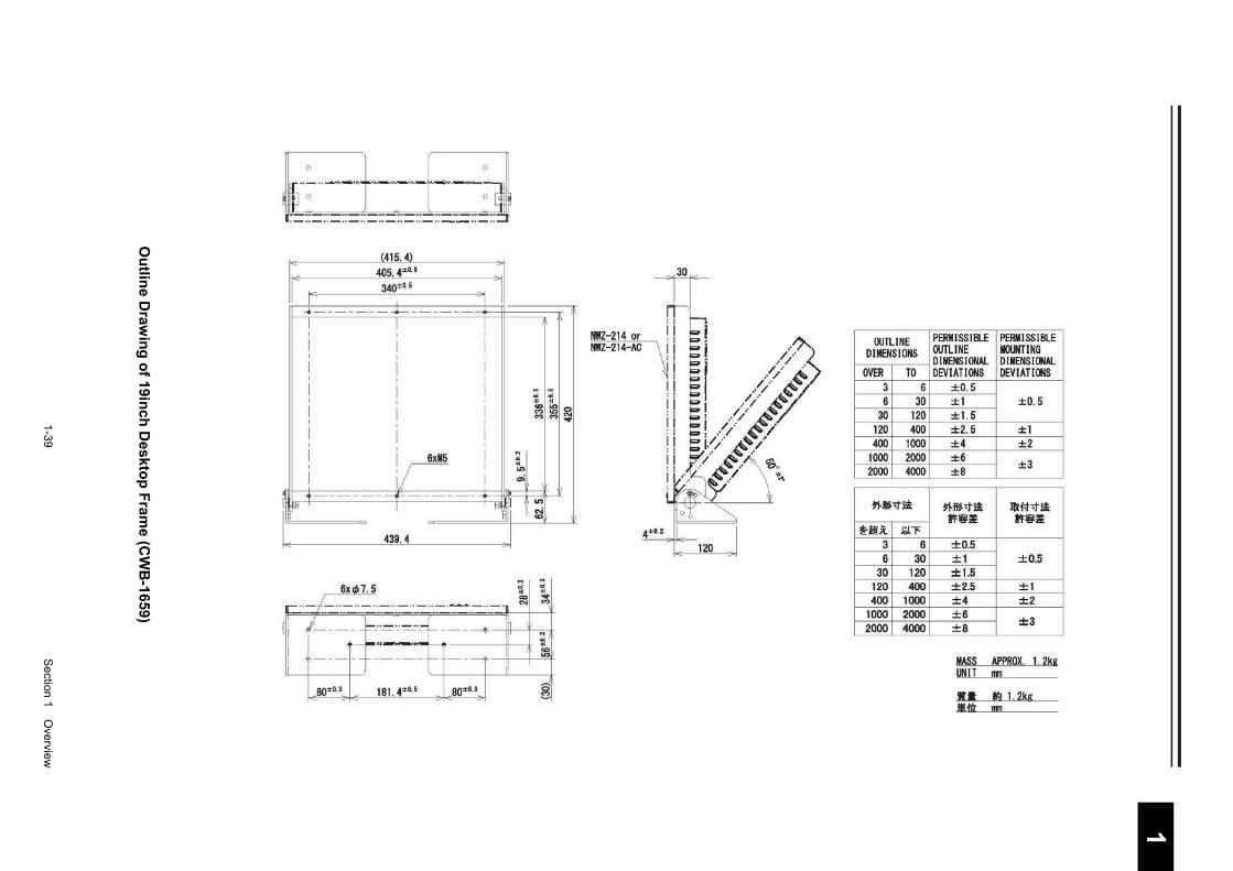
1-39
S
ection 1 Overview
1 2 3 4 5 6 7 8 9
10
11
12
13
14
15
16
17
18
19
20
21
22
23
24
25
26
27
付録
Ou
tline D
rawin
g o
f 19inch
Deskto
p F
rame (C
WB
-1659)
'~~t--f~-j [._ .. _______ .. _ .. _ .. ________ .. _ .. :::B
1: (415. 4) r 405.4±0-· :
1
IE 340±0.5 I
"' _. . ....___ _.__
I I I
~ ~
ci 0 ~ ~ ""It) MIt> M M
i.r .. ~ It)
.,;
~ ---1'- +-lllf I tJJ
It)
~
- 439.4 -
Gxl/>7.5
r- .. - I- .. - ··- .. - .. - ··- .. - ·- -- .. - · ~ ... M
j---- -F-.:·=~ ~·-t---- ---+ --ill----l 1i -~ . ---~-t·~11--- il t ;
.80±03 181.4±0.5 .80±03 ,J_ 0 0
I
~
I
J]~
NWZ-214 or ! NWZ-214-AC ~
4±0.2
l ! /'/'
I ,•/ ) /- .
/~;/~~ I .·/ ~~' ' // -~ I / .· .A.: '.•/ ~--.1-~/ 4..~-/
-/ -~-/ ' .. ~~/~ 'So
~· \ ~
120
OUTLINE PERM ISS I BLE PERMISSIBLE DIMENSIONS OUTLINE MOUNTING
D I MENS I ONAL DIMENSIONAL OVER TO DEVIATIONS DEVIATIONS
3 6 ±0. 5 6 30 ±1 ±0. 5
30 120 +1.5 120 400 ±2.5 ±1 400 1000 ±4 ±2
1000 2000 ±6 ±3
2000 4000 ±8
~5-t;i ~5-t;i !Dit-t-t-1! fif;ll fif;ll
~·.it lOll' 3 6 ±0.5 6 30 ±1 ±0.5
30 120 ±1.5 120 400 ±2.5 ±1 400 1000 ±4 ±2
1000 2000 ±6 ±3
2000 4000 ±8
MASS APPROX 1 2kg UNIT nm
•• fl12kg .!l!.fi'r 1!111
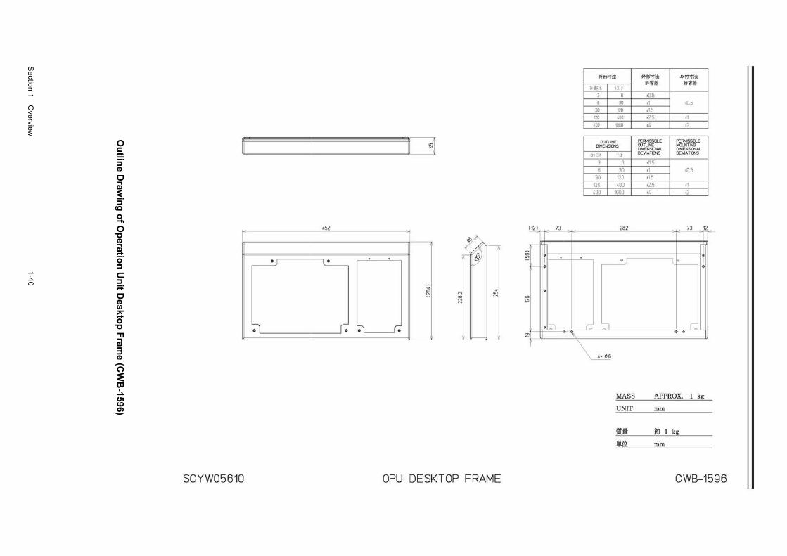
Section 1 O
verview
1-40
Ou
tline D
rawin
g o
f Op
eration
Un
it Deskto
p F
rame (C
WB
-1596)
"-----------------"0
452
•
• • • •
._,. <D N (Y)
~ ._,. LD N
SCYW05610 OPU DESKTOP FRAME
I 121
cr> LD :
-----
73
:----- . <D "-
~
~
·~ >--
\
71-~-tit
~~~ I fH 6
30
3o I 120
120 1 400
4oo I 1000
OUTLINE DIMENSIONS
OVER TO
3 6 6 30
30 120 120 400 400 1000
282
$
r::: ':l
MASS
UNIT
i£1: lji{\L
71-~-tit I
liXfHit wc?6~ wc?6~
±0.5 ±1 ±0 5 ±1.5 ±2.5 ±1 ±4 ±2
PERMISSIBLE PERMISSIBLE OUTLINE MOUNTING DIMENSIONAL DIMENSIONAL DEVIATIONS DEVIATIONS
±0.5 ±1 ±0.5 ±1.5 ±2.5 ±1 ±4 ±2
73 12
l~ •
1: .
APPROX. 1 kg
mm
~ 1 kg
mm
CWB-1596
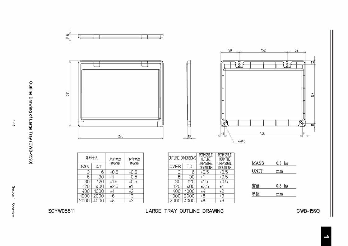
1-41
S
ection 1 Overview
1 2 3 4 5 6 7 8 9
10
11
12
13
14
15
16
17
18
19
20
21
22
23
24
25
26
27
付録
Ou
tline D
rawin
g o
f Larg
e Tray (C
WB
-1593)
~~=~ 59 152 59
I I I I
LJ LJ ~ [Jl. N
( I \..~J II II II \.~J II ~~
0 r:::i
...... ~
n ~ ~' II II II II II f~~
- 270 -11 _\ 248 J11 I JL
*-~"1)! *-~"1)! JlX#-ti! OUTLINE DIMENSIONS PERMISSIIU PERMISSilE
OUTLINE MOUNTING
Hili Wf~~ ~~~
J:J:T OVER TO D~ENSIONAL DIMEN~ONAL DEVIATIONS DEVIATIONS
MASS 0.3 kg
3 6 ±0.5 ±0.5 3 6 ±0.5 ±0.5 UNIT mm
6 30 ±1 ±0.5 6 30 ±1 ±0.5 30 120 ±1.5 ±0.5 30 120 ±1.5 ±0.5
120 400 ±2.5 ±1 120 400 ±2.5 ±1 WI: 0.3 kg 400 1000 ±4 ±2
1000 2000 ±6 ±3 400 1000 ±4 ±2
1000 2000 ±6 ±3 .ljifll: mm
2000 4000 ±8 ±3 2000 4000 ±8 ±3
SCYW05611 LARGE TRAY OUTLINE DRAWING CWB-1593
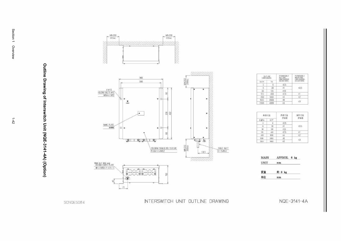
Section 1 O
verview
1-42
Ou
tline D
rawin
g o
f Intersw
itch U
nit (N
QE
-3141-4A) (O
ptio
n)
SCNOE50B4
350 ---330
~ ~ .... HQDNG BQTS MIOJ~ ~
Ja.f1>J:i~l- M10 "' . ® f-.. -"~~-I
ID N ~ N N ~
NAME PeATE / 0 • 0 Of-
\ ~
"'
1 CQffiN4 SEMI-{)LQSS TEX, v"" I ~ · N4M>MN0.2
HQDNG EARTH PeAl E I WNG NUT IM51 i>1d ~==:;::==~::;~::::;:::;~11] ~·""'""'~~ ; ;-- --· '~ ;_ .
// 9r;-~[_ v
n _ •
No ~v"' z:~ :>;N
'///////
INTERSWITCH UNIT OUTLINE DRAWING
OJTLNE DMENS!ct.JS
OVER TO
3 6 5 30
30 120 12) 400 400 1000
100) 2000 2000 4000
71-~l'lit
Hili :l
ll
31)
121l
400
1000
200)
MASS
UNIT
~t:i:
Jl!lfll:
Ul' 6
30
120
400
1000
2000
4000
PERMISSIBLE PERMlSSB..E a..JTLNE MOONTING DIMENSrnAL DMENSict.JAL DEVIATK:NS DEVIATICJ'.JS
±0.5 ±1 ±0.5 ±1.5 ±2.5 ±1 ±4 ±2 ±6 ±8
±3
?1-M 'lit W1H it m>~> i'l'l<i>
±0.5 ±1 ±0.5 ±1.5 ±2.5 ±1 ±4 ±2 ±6 ±8
±3
APPROX. 6 kg
mm
f.J 6 kg
mm
NOE-3141-4A
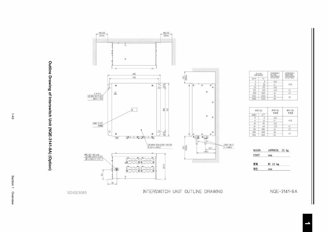
1-43
S
ection 1 Overview
1 2 3 4 5 6 7 8 9
10
11
12
13
14
15
16
17
18
19
20
21
22
23
24
25
26
27
付録
Ou
tline D
rawin
g o
f Intersw
itch U
nit (N
QE
-3141-8A) (O
ptio
n)
4-<' 15.5 HQDNG BQ IS M12
ll(f.J;t:M M12
WNG NUT IM51 a"d HQDNG EARTH ltATE tV 'l' HMSH r - J..t ll- r
SCNOE5085
~ ~
0 -
0 0
~ I ~
CQIRN4 SEMI-BLOSS TEXTURE ~ oN4" " *ND.2
0~~ ~~
0
N
~
~[~ ~
~[~-7TTTT77777777
INTERSWITCH UNIT OUTLINE DRAWING
OJTLNE DMENSI()>jS
OVER TO
] 5
6 30 30 120
120 400 400 1000
1000 2000 2000 4000
I M l'li!i
I Hill UT 3 6
I 6 30
I 30 120
120 400
<DO 1000
I 1000 2000
1 zooo 4000
MASS
UNIT
'itlil: Iii {it
PERMISSIBLE PEMMJSSB...E OJTLNE MWNT!NG DIMENSK:NAL DMENSIO\IAL OEVlATK:NS DEVIATIO'JS
±0.5 ±1 ±0.5 +1.5 +2.5 +1 ±4 ±2 ±6
±3 ±5
9j-l[j;jiJi ~1t-tiii
·~"'" *"'" ±0.5 ±1 ±0.5 +1.5 +2.5 +1 ±4 ±2 ±5 ±5
±3
APPROX. 12 kg
mm
IS 12 kg
mm
NOE -3141-8A
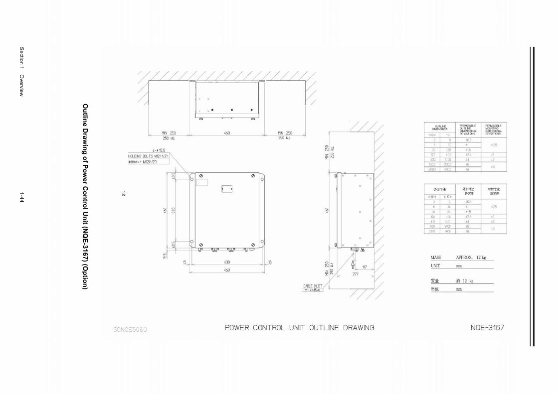
Section 1 O
verview
1-44
Ou
tline D
rawin
g o
f Po
wer C
on
trol U
nit (N
QE
-3167) (Op
tion
)
r = ~
f 0
0 • . . c:i c:i
MIN 250 -- 460 -- MIN 250 ///// OJTLi'JE PER.11SSELE PER.11SSRE
DIMENSIJNS OJTLi'JE MOJNTING DIMENSIONAL DIMENSIONAL DEVIATIO<S DEVIATIONS
250 m 250 m ±0.5
4- ~ 15.5 ''-'·-'
HOLDING BOLTS M12 1112'1 llft lj f,ICf M12(1/2'1
'"'
:c ±1 ±0.5
~ 1 : JU '2U ±to :z m ·120 LDO ±2.5 I ±1 ';;"N
400 10CO ±4 ±2 100] 2000 ±6
±3 2000 4000 ±8
1\)
~ ' 0 0 ",~b CJ 0
D !11-Jr:: 'ti* !11-Jr:: 'ti*
I
IIX1i'ti*
L illi I Li!li it:@~ lt?i>'~
G 10.5
I 0 a:> rn
30 ±1 J ±0.5 :$1 I I 0 II l 30 120 ±15
1LO 400 ±2.5 l ±1 4l11J 'Klrlll ±4 I ±2
1000 20:0 ±6 I ±:l 2001) 40:0 ±8
u;'~ ~ 0 0 0
'---' 1 1
15. 430 . 1:
- 460 -. ~ '!"'" MASS APPROX. 12 kg /A;lj.
: 1 ~ OL 117 UNIT mm
""' / 227
r// 'jfl; ~ 12 kg CABLE NLET (, ·
l$i.1i'L t-1/, jf;\D mm
SC j\J0:::::5D t · D POWER CONTROL UNIT OUTLINE DRAWING NOE-3167
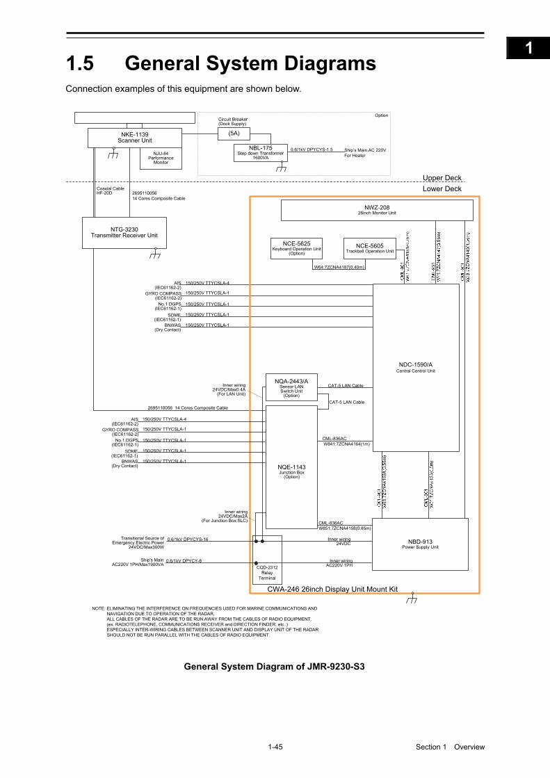
1-45 Section 1 Overview
1
2
3
4
5
6
7
8
9
10
11
12
13
14
15
16
17
18
19
20
21
22
23
24
25
26
27
付録
1.5 General System Diagrams Connection examples of this equipment are shown below.
150/250V TTYCSLA-4AIS(IEC61162-2)
GYRO COMPASS(IEC61162-2)
No.1 DGPS(IEC61162-1)
SDME(IEC61162-1)
BNWAS(Dry Contact)
CML-836ACW851:7ZCNA4158(0.85m)
CML-836ACW841:7ZCNA4164(1m)
CAT-5 LAN Cable
NQE-1143Junction Box
(Option)
Upper Deck
Lower Deck
NKE-1139Scanner Unit
NCE-5605Trackball Operation Unit
NBD-913Power Supply Unit
NJU-84Performance
Monitor
2695110056 14 Cores Composite Cable
NOTE: ELIMINATING THE INTERFERENCE ON FREQUENCIES USED FOR MARINE COMMUNICATIONS AND NAVIGATION DUE TO OPERATION OF THE RADAR,ALL CABLES OF THE RADAR ARE TO BE RUN AWAY FROM THE CABLES OF RADIO EQUIPMENT.(ex. RADIOTELEPHONE, COMMUNICATIONS RECEIVER and DIRECTION FINDER. etc..)ESPECIALLY INTER-WIRING CABLES BETWEEN SCANNER UNIT AND DISPLAY UNIT OF THE RADAR SHOULD NOT BE RUN PARALLEL WITH THE CABLES OF RADIO EQUIPMENT.
150/250V TTYCSLA-1
150/250V TTYCSLA-1
150/250V TTYCSLA-1
150/250V TTYCSLA-1
NWZ-20826inch Monitor Unit
(5A)
NBL-175Step down Transformer
1600VA
0.6/1kV DPYCYS-1.5 Ship’s Main AC 220VFor Heater
Circuit Breaker(Dock Supply)
Option
NTG-3230Transmitter Receiver Unit
NCE-5625Keyboard Operation Unit
(Option)
W64:7ZCNA4187(0.40m)
CWA-246 26inch Display Unit Mount Kit
Coaxial CableHF-20D
150/250V TTYCSLA-4AIS(IEC61162-2)
GYRO COMPASS(IEC61162-2)
No.1 DGPS(IEC61162-1)
SDME(IEC61162-1)
BNWAS(Dry Contact)
150/250V TTYCSLA-1
150/250V TTYCSLA-1
150/250V TTYCSLA-1
150/250V TTYCSLA-1
2695110056 14 Cores Composite Cable
CAT-5 LAN Cable
NDC-1590/ACentral Control Unit
NQA-2443/ASensor LAN Switch Unit
(Option)
Inner wiring24VDC/Max2A
(For Junction Box:SLC)
Inner wiring24VDC/Max0.4A
(For LAN Unit)
CQD-2312Relay
Terminal
Transitional Source ofEmergency Electric Power
24VDC/Max300W
0.6/1kV DPYCYS-16
0.6/1kV DPYCY-6Ship's MainAC220V 1PH/Max1900VA
Inner wiring24VDC
Inner wiringAC220V 1PH
General System Diagram of JMR-9230-S3
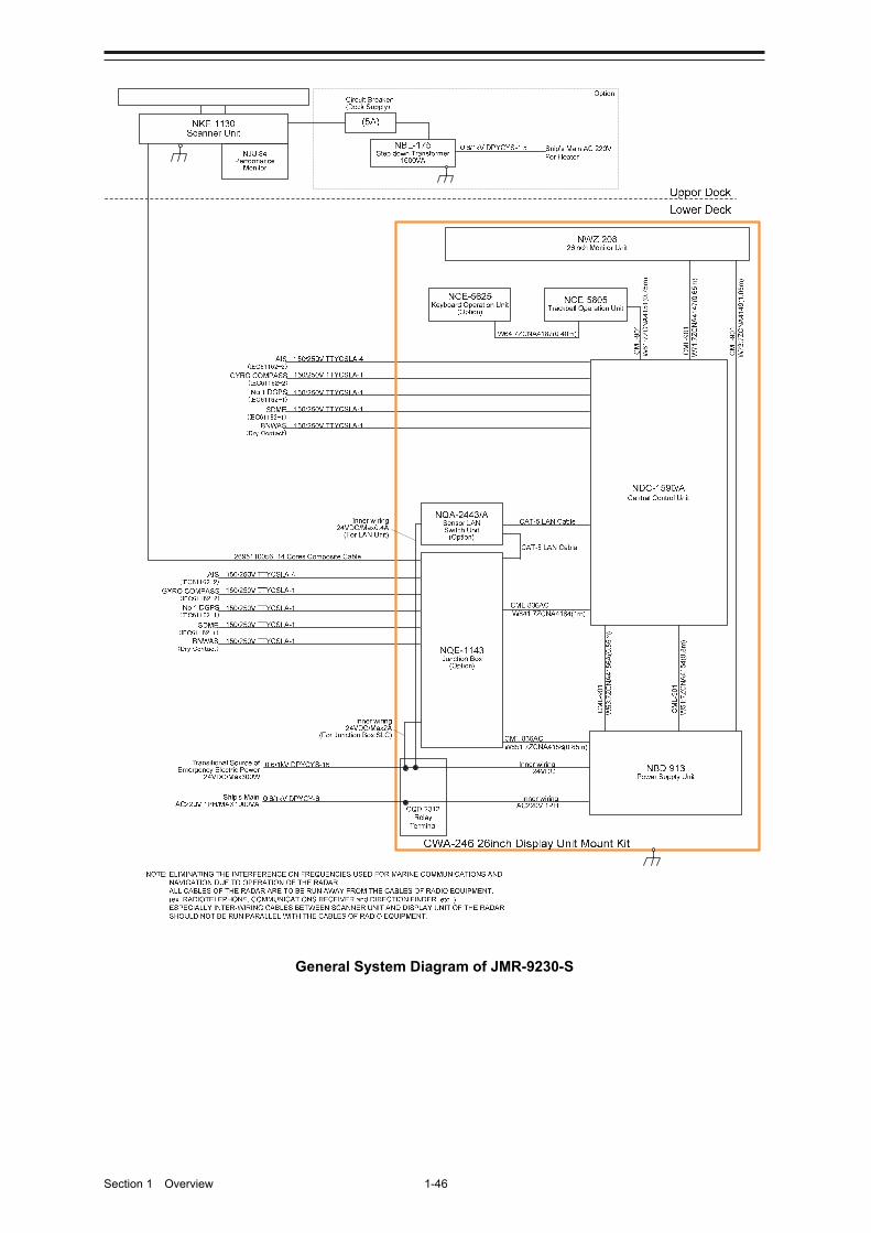
Section 1 Overview 1-46
General System Diagram of JMR-9230-S
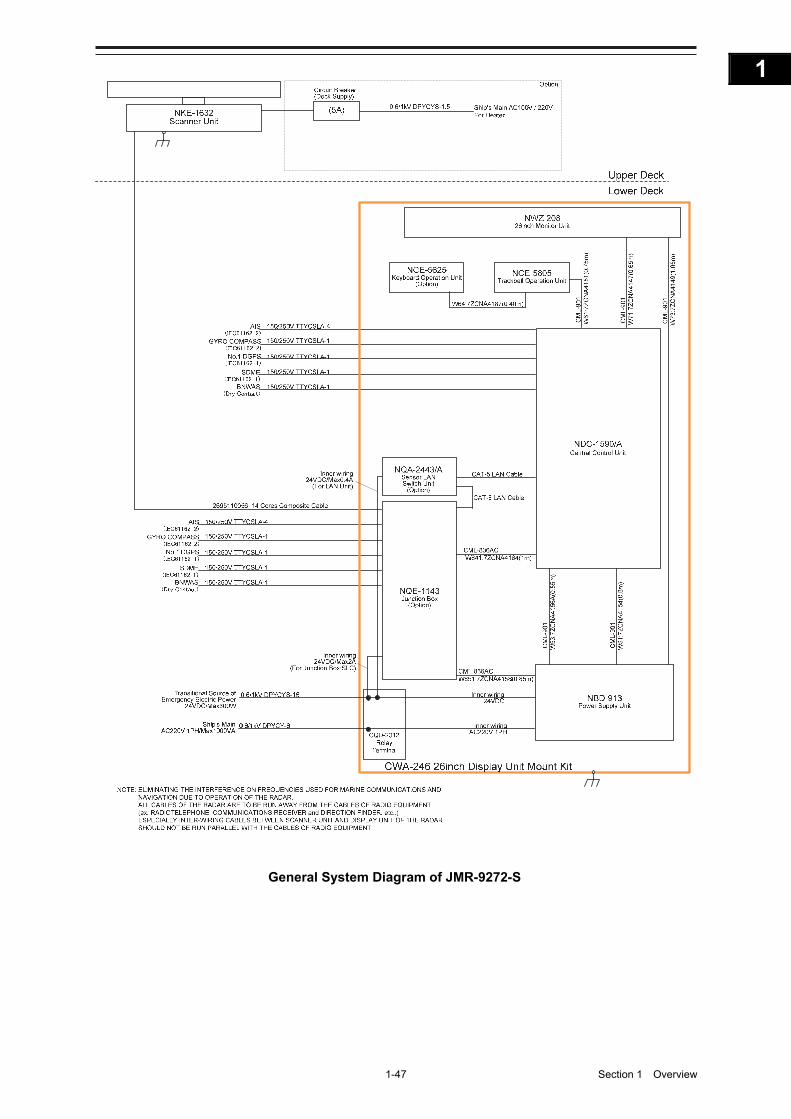
1-47 Section 1 Overview
1
2
3
4
5
6
7
8
9
10
11
12
13
14
15
16
17
18
19
20
21
22
23
24
25
26
27
付録
General System Diagram of JMR-9272-S
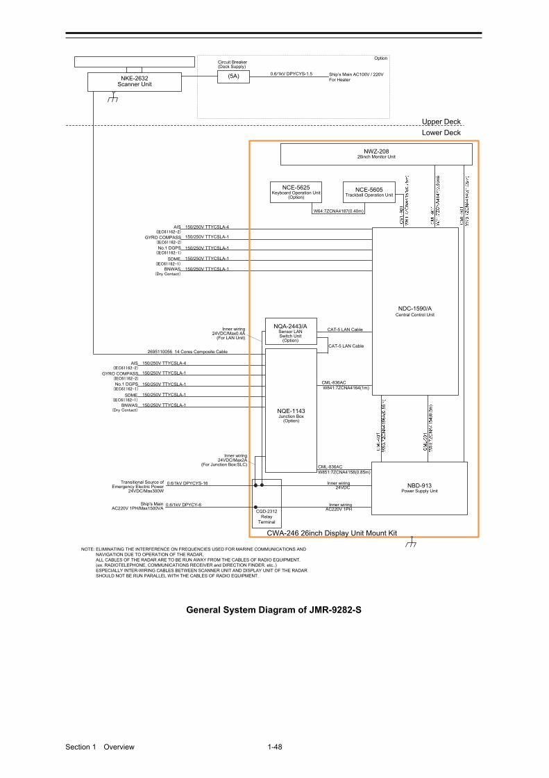
Section 1 Overview 1-48
150/250V TTYCSLA-4AIS(IEC61162-2)
GYRO COMPASS(IEC61162-2)
No.1 DGPS(IEC61162-1)
SDME(IEC61162-1)
BNWAS(Dry Contact)
Upper Deck
Lower Deck
NKE-2632Scanner Unit
2695110056 14 Cores Composite Cable
150/250V TTYCSLA-1
150/250V TTYCSLA-1
150/250V TTYCSLA-1
150/250V TTYCSLA-1
150/250V TTYCSLA-4AIS(IEC61162-2)
GYRO COMPASS(IEC61162-2)
No.1 DGPS(IEC61162-1)
SDME(IEC61162-1)
BNWAS(Dry Contact)
150/250V TTYCSLA-1
150/250V TTYCSLA-1
150/250V TTYCSLA-1
150/250V TTYCSLA-1
(5A)
Circuit Breaker(Dock Supply)
Option
0.6/1kV DPYCYS-1.5 Ship’s Main AC100V / 220VFor Heater
NOTE: ELIMINATING THE INTERFERENCE ON FREQUENCIES USED FOR MARINE COMMUNICATIONS AND NAVIGATION DUE TO OPERATION OF THE RADAR,ALL CABLES OF THE RADAR ARE TO BE RUN AWAY FROM THE CABLES OF RADIO EQUIPMENT.(ex. RADIOTELEPHONE, COMMUNICATIONS RECEIVER and DIRECTION FINDER. etc..)ESPECIALLY INTER-WIRING CABLES BETWEEN SCANNER UNIT AND DISPLAY UNIT OF THE RADAR SHOULD NOT BE RUN PARALLEL WITH THE CABLES OF RADIO EQUIPMENT.
CML-836ACW851:7ZCNA4158(0.85m)
CML-836ACW841:7ZCNA4164(1m)
CAT-5 LAN Cable
NQE-1143Junction Box
(Option)
NCE-5605Trackball Operation Unit
NBD-913Power Supply Unit
NWZ-20826inch Monitor Unit
NCE-5625Keyboard Operation Unit
(Option)
W64:7ZCNA4187(0.40m)
CWA-246 26inch Display Unit Mount Kit
CAT-5 LAN Cable
NDC-1590/ACentral Control Unit
NQA-2443/ASensor LAN Switch Unit
(Option)
Inner wiring24VDC/Max2A
(For Junction Box:SLC)
Inner wiring24VDC/Max0.4A
(For LAN Unit)
CQD-2312Relay
Terminal
Transitional Source ofEmergency Electric Power
24VDC/Max300W
0.6/1kV DPYCYS-16
0.6/1kV DPYCY-6Ship's MainAC220V 1PH/Max1500VA
Inner wiring24VDC
Inner wiringAC220V 1PH
General System Diagram of JMR-9282-S

1-49 Section 1 Overview
1
2
3
4
5
6
7
8
9
10
11
12
13
14
15
16
17
18
19
20
21
22
23
24
25
26
27
付録
150/250V TTYCSLA-4AIS(IEC61162-2)
GYRO COMPASS(IEC61162-2)
No.1 DGPS(IEC61162-1)
SDME(IEC61162-1)
BNWAS(Dry Contact)
Upper Deck
Lower Deck
NKE-2632-HScanner Unit
2695110056 14 Cores Composite Cable
150/250V TTYCSLA-1
150/250V TTYCSLA-1
150/250V TTYCSLA-1
150/250V TTYCSLA-1
150/250V TTYCSLA-4AIS(IEC61162-2)
GYRO COMPASS(IEC61162-2)
No.1 DGPS(IEC61162-1)
SDME(IEC61162-1)
BNWAS(Dry Contact)
150/250V TTYCSLA-1
150/250V TTYCSLA-1
150/250V TTYCSLA-1
150/250V TTYCSLA-1
(5A)
Circuit Breaker(Dock Supply)
Option
0.6/1kV DPYCYS-1.5 Ship’s Main AC100V / 220VFor Heater
NOTE: ELIMINATING THE INTERFERENCE ON FREQUENCIES USED FOR MARINE COMMUNICATIONS AND NAVIGATION DUE TO OPERATION OF THE RADAR,ALL CABLES OF THE RADAR ARE TO BE RUN AWAY FROM THE CABLES OF RADIO EQUIPMENT.(ex. RADIOTELEPHONE, COMMUNICATIONS RECEIVER and DIRECTION FINDER. etc..)ESPECIALLY INTER-WIRING CABLES BETWEEN SCANNER UNIT AND DISPLAY UNIT OF THE RADAR SHOULD NOT BE RUN PARALLEL WITH THE CABLES OF RADIO EQUIPMENT.
CML-836ACW851:7ZCNA4158(0.85m)
CML-836ACW841:7ZCNA4164(1m)
CAT-5 LAN Cable
NQE-1143Junction Box
(Option)
NCE-5605Trackball Operation Unit
NBD-913Power Supply Unit
NWZ-20826inch Monitor Unit
NCE-5625Keyboard Operation Unit
(Option)
W64:7ZCNA4187(0.40m)
CWA-246 26inch Display Unit Mount Kit
CAT-5 LAN Cable
NDC-1590/ACentral Control Unit
NQA-2443/ASensor LAN Switch Unit
(Option)
Inner wiring24VDC/Max2A
(For Junction Box:SLC)
Inner wiring24VDC/Max0.4A
(For LAN Unit)
CQD-2312Relay
Terminal
Transitional Source ofEmergency Electric Power
24VDC/Max300W
0.6/1kV DPYCYS-16
0.6/1kV DPYCY-6Ship's MainAC220V 1PH/MAX1900VA
Inner wiring24VDC
Inner wiringAC220V 1PH
General System Diagram of JMR-9282-SH
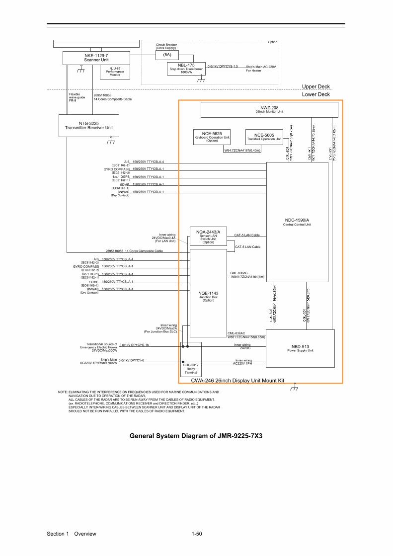
Section 1 Overview 1-50
150/250V TTYCSLA-4AIS(IEC61162-2)
GYRO COMPASS(IEC61162-2)
No.1 DGPS(IEC61162-1)
SDME(IEC61162-1)
BNWAS(Dry Contact)
Upper Deck
Lower Deck
NKE-1129-7Scanner Unit
NJU-85Performance
Monitor
2695110056 14 Cores Composite Cable
150/250V TTYCSLA-1
150/250V TTYCSLA-1
150/250V TTYCSLA-1
150/250V TTYCSLA-1
(5A)
NBL-175Step down Transformer
1600VA
0.6/1kV DPYCYS-1.5 Ship’s Main AC 220VFor Heater
Circuit Breaker(Dock Supply)
Option
NTG-3225Transmitter Receiver Unit
Flexible wave guideFR-9
150/250V TTYCSLA-4AIS(IEC61162-2)
GYRO COMPASS(IEC61162-2)
No.1 DGPS(IEC61162-1)
SDME(IEC61162-1)
BNWAS(Dry Contact)
150/250V TTYCSLA-1
150/250V TTYCSLA-1
150/250V TTYCSLA-1
150/250V TTYCSLA-1
2695110056 14 Cores Composite Cable
NOTE: ELIMINATING THE INTERFERENCE ON FREQUENCIES USED FOR MARINE COMMUNICATIONS AND NAVIGATION DUE TO OPERATION OF THE RADAR,ALL CABLES OF THE RADAR ARE TO BE RUN AWAY FROM THE CABLES OF RADIO EQUIPMENT.(ex. RADIOTELEPHONE, COMMUNICATIONS RECEIVER and DIRECTION FINDER. etc..)ESPECIALLY INTER-WIRING CABLES BETWEEN SCANNER UNIT AND DISPLAY UNIT OF THE RADAR SHOULD NOT BE RUN PARALLEL WITH THE CABLES OF RADIO EQUIPMENT.
CML-836ACW851:7ZCNA4158(0.85m)
CML-836ACW841:7ZCNA4164(1m)
CAT-5 LAN Cable
NQE-1143Junction Box
(Option)
NCE-5605Trackball Operation Unit
NBD-913Power Supply Unit
NWZ-20826inch Monitor Unit
NCE-5625Keyboard Operation Unit
(Option)
W64:7ZCNA4187(0.40m)
CWA-246 26inch Display Unit Mount Kit
CAT-5 LAN Cable
NDC-1590/ACentral Control Unit
NQA-2443/ASensor LAN Switch Unit
(Option)
Inner wiring24VDC/Max2A
(For Junction Box:SLC)
Inner wiring24VDC/Max0.4A
(For LAN Unit)
CQD-2312Relay
Terminal
Transitional Source ofEmergency Electric Power
24VDC/Max300W
0.6/1kV DPYCYS-16
0.6/1kV DPYCY-6Ship's MainAC220V 1PH/Max1700VA
Inner wiring24VDC
Inner wiringAC220V 1PH
General System Diagram of JMR-9225-7X3
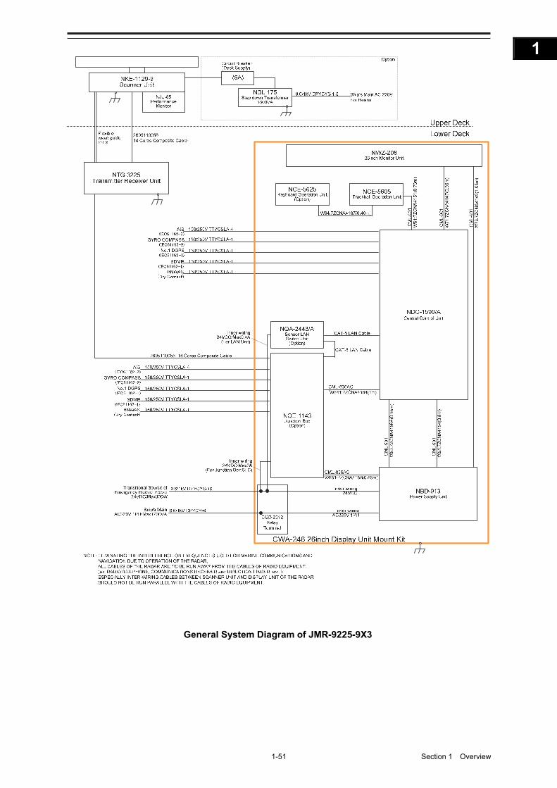
1-51 Section 1 Overview
1
2
3
4
5
6
7
8
9
10
11
12
13
14
15
16
17
18
19
20
21
22
23
24
25
26
27
付録
General System Diagram of JMR-9225-9X3

Section 1 Overview 1-52
General System Diagram of JMR-9225-6X

1-53 Section 1 Overview
1
2
3
4
5
6
7
8
9
10
11
12
13
14
15
16
17
18
19
20
21
22
23
24
25
26
27
付録
General System Diagram of JMR-9225-9X
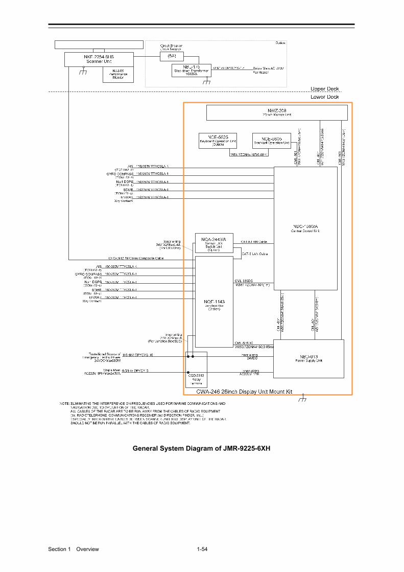
Section 1 Overview 1-54
General System Diagram of JMR-9225-6XH

1-55 Section 1 Overview
1
2
3
4
5
6
7
8
9
10
11
12
13
14
15
16
17
18
19
20
21
22
23
24
25
26
27
付録
150/250V TTYCSLA-4AIS(IEC61162-2)
GYRO COMPASS(IEC61162-2)
No.1 DGPS(IEC61162-1)
SDME(IEC61162-1)
BNWAS(Dry Contact)
Upper Deck
Lower Deck
NKE-2103-6Scanner Unit
NJU-85Performance
Monitor
CFQ-6912 19 Cores Composite Cable
150/250V TTYCSLA-1
150/250V TTYCSLA-1
150/250V TTYCSLA-1
150/250V TTYCSLA-1
150/250V TTYCSLA-4AIS(IEC61162-2)
GYRO COMPASS(IEC61162-2)
No.1 DGPS(IEC61162-1)
SDME(IEC61162-1)
BNWAS(Dry Contact)
150/250V TTYCSLA-1
150/250V TTYCSLA-1
150/250V TTYCSLA-1
150/250V TTYCSLA-1
NOTE: ELIMINATING THE INTERFERENCE ON FREQUENCIES USED FOR MARINE COMMUNICATIONS AND NAVIGATION DUE TO OPERATION OF THE RADAR,ALL CABLES OF THE RADAR ARE TO BE RUN AWAY FROM THE CABLES OF RADIO EQUIPMENT.(ex. RADIOTELEPHONE, COMMUNICATIONS RECEIVER and DIRECTION FINDER. etc..)ESPECIALLY INTER-WIRING CABLES BETWEEN SCANNER UNIT AND DISPLAY UNIT OF THE RADAR SHOULD NOT BE RUN PARALLEL WITH THE CABLES OF RADIO EQUIPMENT.
CAT-5 LAN Cable
NQE-1143Junction Box
(Option)
NCE-5605Trackball Operation Unit
NBD-913Power Supply Unit
NWZ-20826inch Monitor Unit
NCE-5625Keyboard Operation Unit
(Option)
W64:7ZCNA4187(0.40m)
CWA-246 26inch Display Unit Mount Kit
CAT-5 LAN Cable
NDC-1590/ACentral Control Unit
NQA-2443/ASensor LAN Switch Unit
(Option)
Inner wiring24VDC/Max2A
(For Junction Box:SLC)
Inner wiring24VDC/Max0.4A
(For LAN Unit)
CQD-2312Relay
Terminal
Transitional Source ofEmergency Electric Power
24VDC/Max510W
0.6/1kV DPYCYS-16
0.6/1kV DPYCY-6Ship's MainAC220V 1PH/Max240VA
Inner wiring24VDC
Inner wiringAC220V 1PH
CML-836DCW853:7ZCNA4160(0.85m)
CML-836DCW841:7ZCNA4164(1m)
General System Diagram of JMR-9210-6X
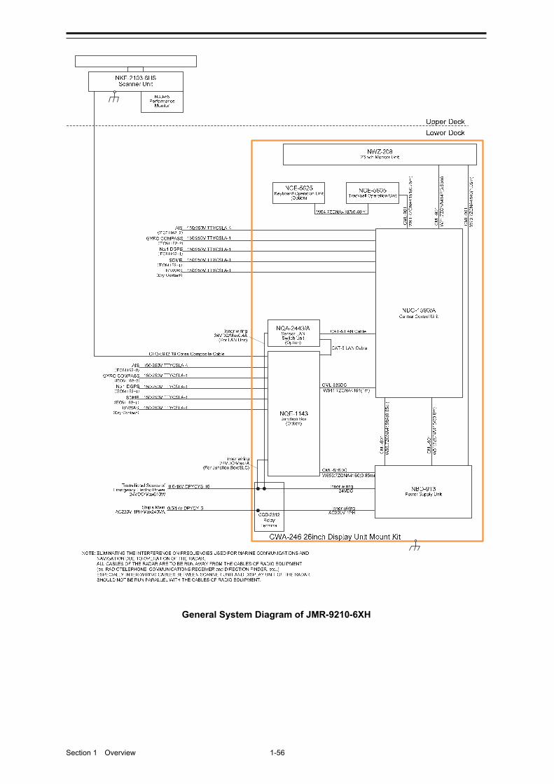
Section 1 Overview 1-56
General System Diagram of JMR-9210-6XH
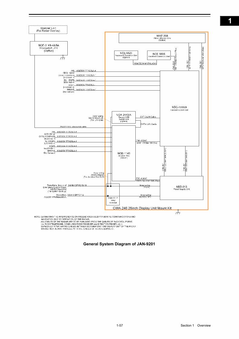
1-57 Section 1 Overview
1
2
3
4
5
6
7
8
9
10
11
12
13
14
15
16
17
18
19
20
21
22
23
24
25
26
27
付録
General System Diagram of JAN-9201
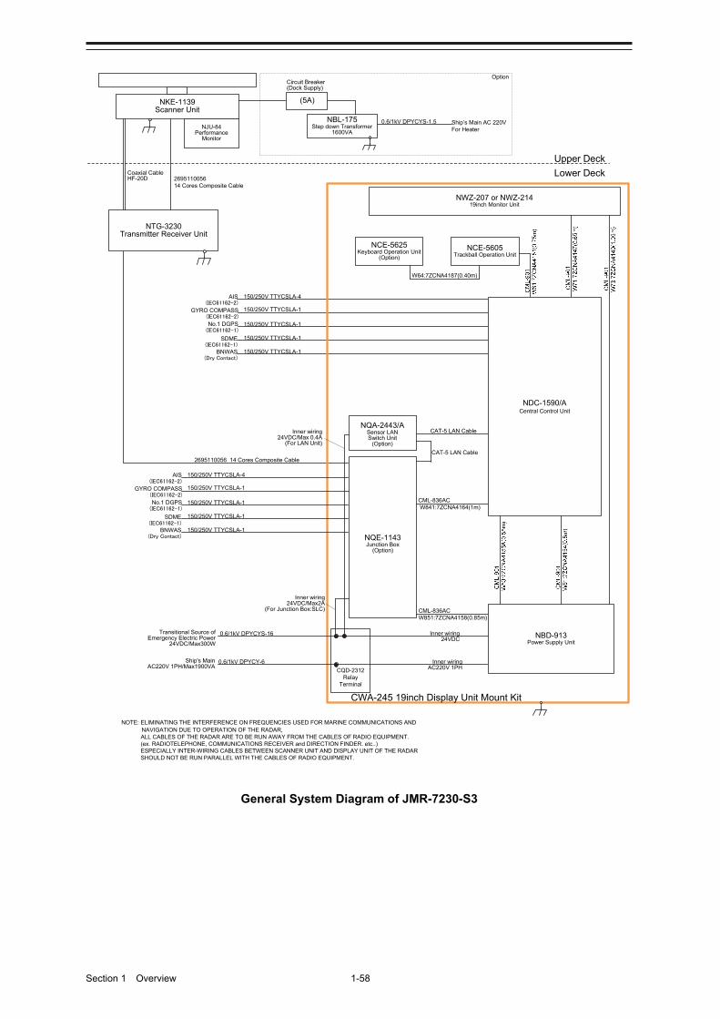
Section 1 Overview 1-58
150/250V TTYCSLA-4AIS(IEC61162-2)
GYRO COMPASS(IEC61162-2)
No.1 DGPS(IEC61162-1)
SDME(IEC61162-1)
BNWAS(Dry Contact)
CML-836ACW851:7ZCNA4158(0.85m)
CML-836ACW841:7ZCNA4164(1m)
CAT-5 LAN Cable
NQE-1143Junction Box
(Option)
Upper Deck
Lower Deck
NKE-1139Scanner Unit
NCE-5605Trackball Operation Unit
NBD-913Power Supply Unit
NJU-84Performance
Monitor
2695110056 14 Cores Composite Cable
NOTE: ELIMINATING THE INTERFERENCE ON FREQUENCIES USED FOR MARINE COMMUNICATIONS AND NAVIGATION DUE TO OPERATION OF THE RADAR,ALL CABLES OF THE RADAR ARE TO BE RUN AWAY FROM THE CABLES OF RADIO EQUIPMENT.(ex. RADIOTELEPHONE, COMMUNICATIONS RECEIVER and DIRECTION FINDER. etc..)ESPECIALLY INTER-WIRING CABLES BETWEEN SCANNER UNIT AND DISPLAY UNIT OF THE RADAR SHOULD NOT BE RUN PARALLEL WITH THE CABLES OF RADIO EQUIPMENT.
150/250V TTYCSLA-1
150/250V TTYCSLA-1
150/250V TTYCSLA-1
150/250V TTYCSLA-1
NWZ-207 or NWZ-21419inch Monitor Unit
(5A)
NBL-175Step down Transformer
1600VA
0.6/1kV DPYCYS-1.5 Ship’s Main AC 220VFor Heater
Circuit Breaker(Dock Supply)
Option
NTG-3230Transmitter Receiver Unit
NCE-5625Keyboard Operation Unit
(Option)
W64:7ZCNA4187(0.40m)
CWA-245 19inch Display Unit Mount Kit
Coaxial CableHF-20D
NQA-2443/ASensor LAN Switch Unit
(Option)
150/250V TTYCSLA-4AIS(IEC61162-2)
GYRO COMPASS(IEC61162-2)
No.1 DGPS(IEC61162-1)
SDME(IEC61162-1)
BNWAS(Dry Contact)
150/250V TTYCSLA-1
150/250V TTYCSLA-1
150/250V TTYCSLA-1
150/250V TTYCSLA-1
2695110056 14 Cores Composite Cable
CAT-5 LAN Cable
NDC-1590/ACentral Control Unit
Inner wiring24VDC/Max2A
(For Junction Box:SLC)
Inner wiring24VDC/Max 0.4A
(For LAN Unit)
CQD-2312Relay
Terminal
Transitional Source ofEmergency Electric Power
24VDC/Max300W
0.6/1kV DPYCYS-16
0.6/1kV DPYCY-6Ship's MainAC220V 1PH/Max1900VA
Inner wiring24VDC
Inner wiringAC220V 1PH
General System Diagram of JMR-7230-S3

1-59 Section 1 Overview
1
2
3
4
5
6
7
8
9
10
11
12
13
14
15
16
17
18
19
20
21
22
23
24
25
26
27
付録
150/250V TTYCSLA-4AIS(IEC61162-2)
GYRO COMPASS(IEC61162-2)
No.1 DGPS(IEC61162-1)
SDME(IEC61162-1)
BNWAS(Dry Contact)
Upper Deck
Lower Deck
NKE-1130Scanner Unit
2695110056 14 Cores Composite Cable
150/250V TTYCSLA-1
150/250V TTYCSLA-1
150/250V TTYCSLA-1
150/250V TTYCSLA-1
(5A)
NBL-175Step down Transformer
1600VA
0.6/1kV DPYCYS-1.5 Ship’s Main AC 220VFor Heater
Circuit Breaker(Dock Supply)
Option
150/250V TTYCSLA-4AIS(IEC61162-2)
GYRO COMPASS(IEC61162-2)
No.1 DGPS(IEC61162-1)
SDME(IEC61162-1)
BNWAS(Dry Contact)
150/250V TTYCSLA-1
150/250V TTYCSLA-1
150/250V TTYCSLA-1
150/250V TTYCSLA-1
NOTE: ELIMINATING THE INTERFERENCE ON FREQUENCIES USED FOR MARINE COMMUNICATIONS AND NAVIGATION DUE TO OPERATION OF THE RADAR,ALL CABLES OF THE RADAR ARE TO BE RUN AWAY FROM THE CABLES OF RADIO EQUIPMENT.(ex. RADIOTELEPHONE, COMMUNICATIONS RECEIVER and DIRECTION FINDER. etc..)ESPECIALLY INTER-WIRING CABLES BETWEEN SCANNER UNIT AND DISPLAY UNIT OF THE RADAR SHOULD NOT BE RUN PARALLEL WITH THE CABLES OF RADIO EQUIPMENT.
CML-836ACW851:7ZCNA4158(0.85m)
CML-836ACW841:7ZCNA4164(1m)
CAT-5 LAN Cable
NQE-1143Junction Box
(Option)
NCE-5605Trackball Operation Unit
NBD-913Power Supply Unit
NWZ-207 or NWZ-21419inch Monitor Unit
NCE-5625Keyboard Operation Unit
(Option)
W64:7ZCNA4187(0.40m)
CWA-245 19inch Display Unit Mount Kit
NQA-2443/ASensor LAN Switch Unit
(Option)
CAT-5 LAN Cable
NDC-1590/ACentral Control Unit
Inner wiring24VDC/Max2A
(For Junction Box:SLC)
Inner wiring24VDC/Max0.4A
(For LAN Unit)
CQD-2312Relay
Terminal
Transitional Source ofEmergency Electric Power
24VDC/Max300W
0.6/1kV DPYCYS-16
0.6/1kV DPYCY-6Ship's MainAC220V 1PH/Max1900VA
Inner wiring24VDC
Inner wiringAC220V 1PH
NJU-84Performance
Monitor(Option)
General System Diagram of JMR-7230-S
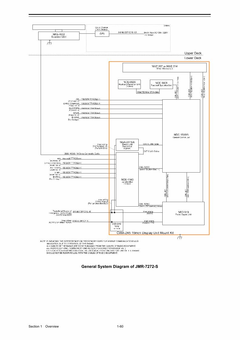
Section 1 Overview 1-60
General System Diagram of JMR-7272-S
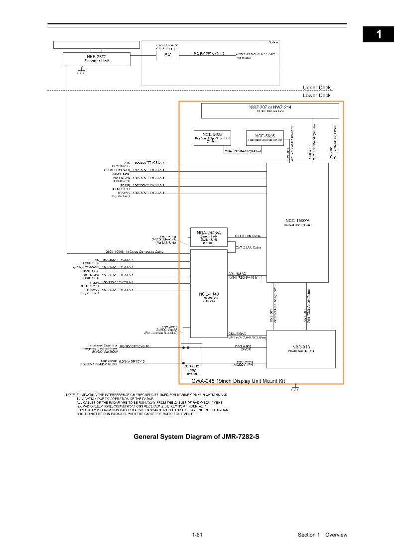
1-61 Section 1 Overview
1
2
3
4
5
6
7
8
9
10
11
12
13
14
15
16
17
18
19
20
21
22
23
24
25
26
27
付録
General System Diagram of JMR-7282-S
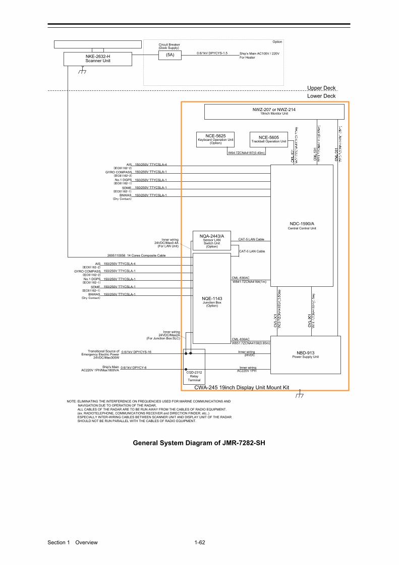
Section 1 Overview 1-62
150/250V TTYCSLA-4AIS(IEC61162-2)
GYRO COMPASS(IEC61162-2)
No.1 DGPS(IEC61162-1)
SDME(IEC61162-1)
BNWAS(Dry Contact)
Upper Deck
Lower Deck
NKE-2632-HScanner Unit
2695110056 14 Cores Composite Cable
150/250V TTYCSLA-1
150/250V TTYCSLA-1
150/250V TTYCSLA-1
150/250V TTYCSLA-1
Inner wiring24VDC/Max2A
(For Junction Box:SLC)
Inner wiring24VDC/Max0.4A
(For LAN Unit)
150/250V TTYCSLA-4AIS(IEC61162-2)
GYRO COMPASS(IEC61162-2)
No.1 DGPS(IEC61162-1)
SDME(IEC61162-1)
BNWAS(Dry Contact)
150/250V TTYCSLA-1
150/250V TTYCSLA-1
150/250V TTYCSLA-1
150/250V TTYCSLA-1
(5A)
Circuit Breaker(Dock Supply)
Option
0.6/1kV DPYCYS-1.5 Ship’s Main AC100V / 220VFor Heater
NOTE: ELIMINATING THE INTERFERENCE ON FREQUENCIES USED FOR MARINE COMMUNICATIONS AND NAVIGATION DUE TO OPERATION OF THE RADAR, ALL CABLES OF THE RADAR ARE TO BE RUN AWAY FROM THE CABLES OF RADIO EQUIPMENT.(ex. RADIOTELEPHONE, COMMUNICATIONS RECEIVER and DIRECTION FINDER. etc..)ESPECIALLY INTER-WIRING CABLES BETWEEN SCANNER UNIT AND DISPLAY UNIT OF THE RADAR SHOULD NOT BE RUN PARALLEL WITH THE CABLES OF RADIO EQUIPMENT.
CML-836ACW851:7ZCNA4158(0.85m)
CML-836ACW841:7ZCNA4164(1m)
CAT-5 LAN Cable
NQE-1143Junction Box
(Option)
NCE-5605Trackball Operation Unit
NBD-913Power Supply Unit
NWZ-207 or NWZ-21419inch Monitor Unit
NCE-5625Keyboard Operation Unit
(Option)
W64:7ZCNA4187(0.40m)
CWA-245 19inch Display Unit Mount Kit
NQA-2443/ASensor LAN Switch Unit
(Option)
CAT-5 LAN Cable
NDC-1590/ACentral Control Unit
CQD-2312Relay
Terminal
Transitional Source ofEmergency Electric Power
24VDC/Max300W
0.6/1kV DPYCYS-16
0.6/1kV DPYCY-6Ship's MainAC220V 1PH/Max1800VA
Inner wiring24VDC
Inner wiringAC220V 1PH
General System Diagram of JMR-7282-SH
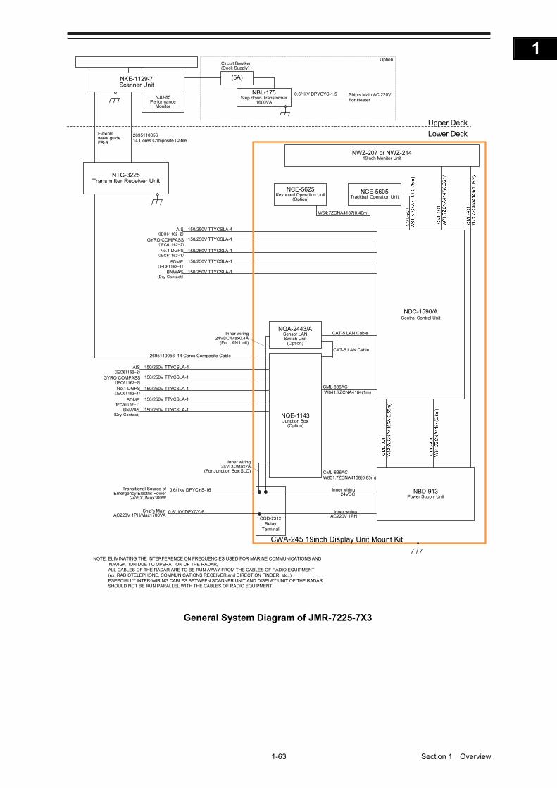
1-63 Section 1 Overview
1
2
3
4
5
6
7
8
9
10
11
12
13
14
15
16
17
18
19
20
21
22
23
24
25
26
27
付録
150/250V TTYCSLA-4AIS(IEC61162-2)
GYRO COMPASS(IEC61162-2)
No.1 DGPS(IEC61162-1)
SDME(IEC61162-1)
BNWAS(Dry Contact)
Upper Deck
Lower Deck
NKE-1129-7Scanner Unit
NJU-85Performance
Monitor
2695110056 14 Cores Composite Cable
150/250V TTYCSLA-1
150/250V TTYCSLA-1
150/250V TTYCSLA-1
150/250V TTYCSLA-1
(5A)
NBL-175Step down Transformer
1600VA
0.6/1kV DPYCYS-1.5 Ship’s Main AC 220VFor Heater
Circuit Breaker(Dock Supply)
Option
NTG-3225Transmitter Receiver Unit
Flexible wave guideFR-9
150/250V TTYCSLA-4AIS(IEC61162-2)
GYRO COMPASS(IEC61162-2)
No.1 DGPS(IEC61162-1)
SDME(IEC61162-1)
BNWAS(Dry Contact)
150/250V TTYCSLA-1
150/250V TTYCSLA-1
150/250V TTYCSLA-1
150/250V TTYCSLA-1
2695110056 14 Cores Composite Cable
NOTE: ELIMINATING THE INTERFERENCE ON FREQUENCIES USED FOR MARINE COMMUNICATIONS AND NAVIGATION DUE TO OPERATION OF THE RADAR,ALL CABLES OF THE RADAR ARE TO BE RUN AWAY FROM THE CABLES OF RADIO EQUIPMENT.(ex. RADIOTELEPHONE, COMMUNICATIONS RECEIVER and DIRECTION FINDER. etc..)ESPECIALLY INTER-WIRING CABLES BETWEEN SCANNER UNIT AND DISPLAY UNIT OF THE RADAR SHOULD NOT BE RUN PARALLEL WITH THE CABLES OF RADIO EQUIPMENT.
CML-836ACW851:7ZCNA4158(0.85m)
CML-836ACW841:7ZCNA4164(1m)
CAT-5 LAN Cable
NQE-1143Junction Box
(Option)
NCE-5605Trackball Operation Unit
NBD-913Power Supply Unit
NWZ-207 or NWZ-21419inch Monitor Unit
NCE-5625Keyboard Operation Unit
(Option)
W64:7ZCNA4187(0.40m)
CWA-245 19inch Display Unit Mount Kit
NQA-2443/ASensor LAN Switch Unit
(Option)
CAT-5 LAN Cable
NDC-1590/ACentral Control Unit
Inner wiring24VDC/Max2A
(For Junction Box:SLC)
Inner wiring24VDC/Max0.4A
(For LAN Unit)
CQD-2312Relay
Terminal
Transitional Source ofEmergency Electric Power
24VDC/Max300W
0.6/1kV DPYCYS-16
0.6/1kV DPYCY-6Ship's MainAC220V 1PH/Max1700VA
Inner wiring24VDC
Inner wiringAC220V 1PH
General System Diagram of JMR-7225-7X3
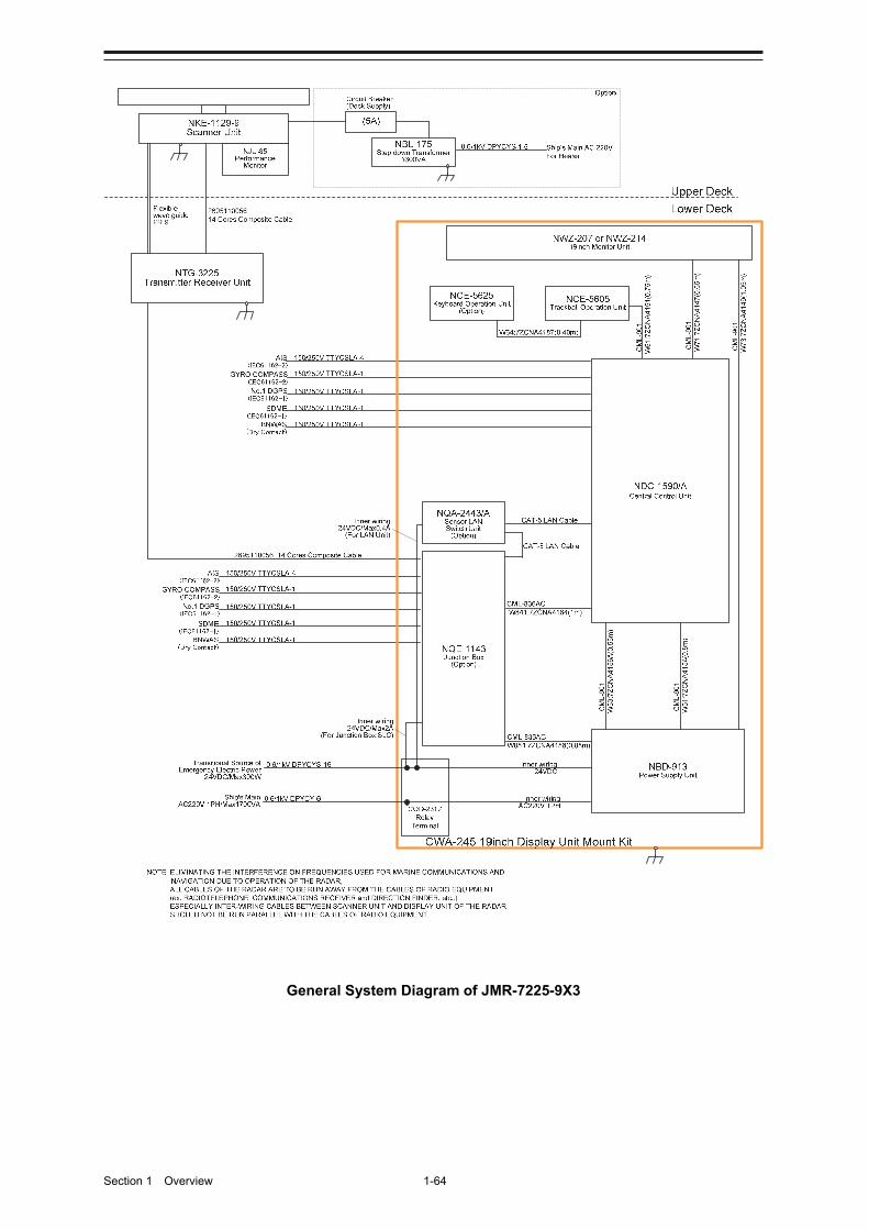
Section 1 Overview 1-64
General System Diagram of JMR-7225-9X3

1-65 Section 1 Overview
1
2
3
4
5
6
7
8
9
10
11
12
13
14
15
16
17
18
19
20
21
22
23
24
25
26
27
付録
150/250V TTYCSLA-4AIS(IEC61162-2)
GYRO COMPASS(IEC61162-2)
No.1 DGPS(IEC61162-1)
SDME(IEC61162-1)
BNWAS(Dry Contact)
Upper Deck
Lower Deck
NKE-1125-6Scanner Unit
NJU-85Performance
Monitor
2695110056 14 Cores Composite Cable
150/250V TTYCSLA-1
150/250V TTYCSLA-1
150/250V TTYCSLA-1
150/250V TTYCSLA-1
(5A)
NBL-175Step down Transformer
1600VA
0.6/1kV DPYCYS-1.5 Ship’s Main AC 220VFor Heater
Circuit Breaker(Dock Supply)
Option
150/250V TTYCSLA-4AIS(IEC61162-2)
GYRO COMPASS(IEC61162-2)
No.1 DGPS(IEC61162-1)
SDME(IEC61162-1)
BNWAS(Dry Contact)
150/250V TTYCSLA-1
150/250V TTYCSLA-1
150/250V TTYCSLA-1
150/250V TTYCSLA-1
NOTE: ELIMINATING THE INTERFERENCE ON FREQUENCIES USED FOR MARINE COMMUNICATIONS AND NAVIGATION DUE TO OPERATION OF THE RADAR,ALL CABLES OF THE RADAR ARE TO BE RUN AWAY FROM THE CABLES OF RADIO EQUIPMENT.(ex. RADIOTELEPHONE, COMMUNICATIONS RECEIVER and DIRECTION FINDER. etc..)ESPECIALLY INTER-WIRING CABLES BETWEEN SCANNER UNIT AND DISPLAY UNIT OF THE RADAR SHOULD NOT BE RUN PARALLEL WITH THE CABLES OF RADIO EQUIPMENT.
CML-836ACW851:7ZCNA4158(0.85m)
CML-836ACW841:7ZCNA4164(1m)
CAT-5 LAN Cable
NQE-1143Junction Box
(Option)
NCE-5605Trackball Operation Unit
NBD-913Power Supply Unit
NWZ-207 or NWZ-21419inch Monitor Unit
NCE-5625Keyboard Operation Unit
(Option)
W64:7ZCNA4187(0.40m)
CWA-245 19inch Display Unit Mount Kit
NQA-2443/ASensor LAN Switch Unit
(Option)
CAT-5 LAN Cable
NDC-1590/ACentral Control Unit
Inner wiring24VDC/Max2A
(For Junction Box:SLC)
Inner wiring24VDC/Max0.4A
(For LAN Unit)
CQD-2312Relay
Terminal
Transitional Source ofEmergency Electric Power
24VDC/Max300W
0.6/1kV DPYCYS-16
0.6/1kV DPYCY-6Ship's MainAC220V 1PH/Max1700VA
Inner wiring24VDC
Inner wiringAC220V 1PH
General System Diagram of JMR-7225-6X
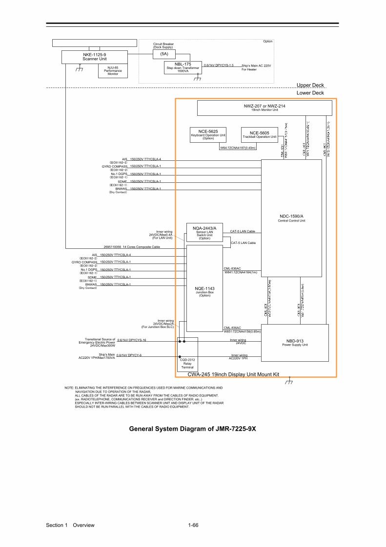
Section 1 Overview 1-66
150/250V TTYCSLA-4AIS(IEC61162-2)
GYRO COMPASS(IEC61162-2)
No.1 DGPS(IEC61162-1)
SDME(IEC61162-1)
BNWAS(Dry Contact)
Upper Deck
Lower Deck
NKE-1125-9Scanner Unit
NJU-85Performance
Monitor
2695110056 14 Cores Composite Cable
150/250V TTYCSLA-1
150/250V TTYCSLA-1
150/250V TTYCSLA-1
150/250V TTYCSLA-1
(5A)
NBL-175Step down Transformer
1600VA
0.6/1kV DPYCYS-1.5 Ship’s Main AC 220VFor Heater
Circuit Breaker(Dock Supply)
Option
150/250V TTYCSLA-4AIS(IEC61162-2)
GYRO COMPASS(IEC61162-2)
No.1 DGPS(IEC61162-1)
SDME(IEC61162-1)
BNWAS(Dry Contact)
150/250V TTYCSLA-1
150/250V TTYCSLA-1
150/250V TTYCSLA-1
150/250V TTYCSLA-1
NOTE: ELIMINATING THE INTERFERENCE ON FREQUENCIES USED FOR MARINE COMMUNICATIONS AND NAVIGATION DUE TO OPERATION OF THE RADAR,ALL CABLES OF THE RADAR ARE TO BE RUN AWAY FROM THE CABLES OF RADIO EQUIPMENT.(ex. RADIOTELEPHONE, COMMUNICATIONS RECEIVER and DIRECTION FINDER. etc..)ESPECIALLY INTER-WIRING CABLES BETWEEN SCANNER UNIT AND DISPLAY UNIT OF THE RADAR SHOULD NOT BE RUN PARALLEL WITH THE CABLES OF RADIO EQUIPMENT.
CML-836ACW851:7ZCNA4158(0.85m)
CML-836ACW841:7ZCNA4164(1m)
CAT-5 LAN Cable
NQE-1143Junction Box
(Option)
NCE-5605Trackball Operation Unit
NBD-913Power Supply Unit
NWZ-207 or NWZ-21419inch Monitor Unit
NCE-5625Keyboard Operation Unit
(Option)
W64:7ZCNA4187(0.40m)
CWA-245 19inch Display Unit Mount Kit
NQA-2443/ASensor LAN Switch Unit
(Option)
CAT-5 LAN Cable
NDC-1590/ACentral Control Unit
Inner wiring24VDC/Max2A
(For Junction Box:SLC)
Inner wiring24VDC/Max0.4A
(For LAN Unit)
CQD-2312Relay
Terminal
Transitional Source ofEmergency Electric Power
24VDC/Max300W
0.6/1kV DPYCYS-16
0.6/1kV DPYCY-6Ship's MainAC220V 1PH/Max1700VA
Inner wiring24VDC
Inner wiringAC220V 1PH
General System Diagram of JMR-7225-9X
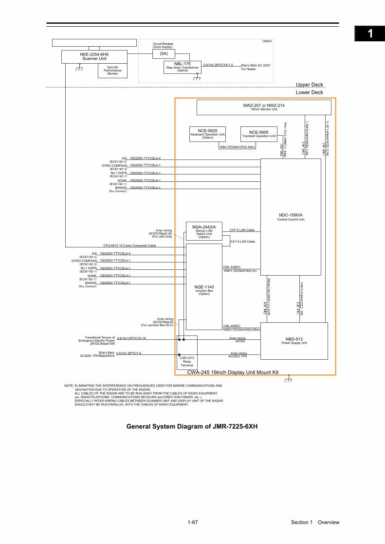
1-67 Section 1 Overview
1
2
3
4
5
6
7
8
9
10
11
12
13
14
15
16
17
18
19
20
21
22
23
24
25
26
27
付録
150/250V TTYCSLA-4AIS(IEC61162-2)
GYRO COMPASS(IEC61162-2)
No.1 DGPS(IEC61162-1)
SDME(IEC61162-1)
BNWAS(Dry Contact)
Upper Deck
Lower Deck
NKE-2254-6HSScanner Unit
NJU-85Performance
Monitor
CFQ-6912 19 Cores Composite Cable
150/250V TTYCSLA-1
150/250V TTYCSLA-1
150/250V TTYCSLA-1
150/250V TTYCSLA-1
(5A)
NBL-175Step down Transformer
1600VA
0.6/1kV DPYCYS-1.5 Ship’s Main AC 220VFor Heater
Circuit Breaker(Dock Supply)
Option
150/250V TTYCSLA-4AIS(IEC61162-2)
GYRO COMPASS(IEC61162-2)
No.1 DGPS(IEC61162-1)
SDME(IEC61162-1)
BNWAS(Dry Contact)
150/250V TTYCSLA-1
150/250V TTYCSLA-1
150/250V TTYCSLA-1
150/250V TTYCSLA-1
NOTE: ELIMINATING THE INTERFERENCE ON FREQUENCIES USED FOR MARINE COMMUNICATIONS AND NAVIGATION DUE TO OPERATION OF THE RADAR,ALL CABLES OF THE RADAR ARE TO BE RUN AWAY FROM THE CABLES OF RADIO EQUIPMENT.(ex. RADIOTELEPHONE, COMMUNICATIONS RECEIVER and DIRECTION FINDER. etc..)ESPECIALLY INTER-WIRING CABLES BETWEEN SCANNER UNIT AND DISPLAY UNIT OF THE RADAR SHOULD NOT BE RUN PARALLEL WITH THE CABLES OF RADIO EQUIPMENT.
CML-836DCW853:7ZCNA4160(0.85m)
CML-836DCW841:7ZCNA4164(1m)
CAT-5 LAN Cable
NQE-1143Junction Box
(Option)
NCE-5605Trackball Operation Unit
NBD-913Power Supply Unit
NWZ-207 or NWZ-21419inch Monitor Unit
NCE-5625Keyboard Operation Unit
(Option)
W64:7ZCNA4187(0.40m)
CWA-245 19inch Display Unit Mount Kit
NQA-2443/ASensor LAN Switch Unit
(Option)
CAT-5 LAN Cable
NDC-1590/ACentral Control Unit
Inner wiring24VDC/Max2A
(For Junction Box:SLC)
Inner wiring24VDC/Max0.4A
(For LAN Unit)
CQD-2312Relay
Terminal
Transitional Source ofEmergency Electric Power
24VDC/Max610W
0.6/1kV DPYCYS-16
0.6/1kV DPYCY-6Ship's MainAC220V 1PH/Max240VA
Inner wiring24VDC
Inner wiringAC220V 1PH
General System Diagram of JMR-7225-6XH
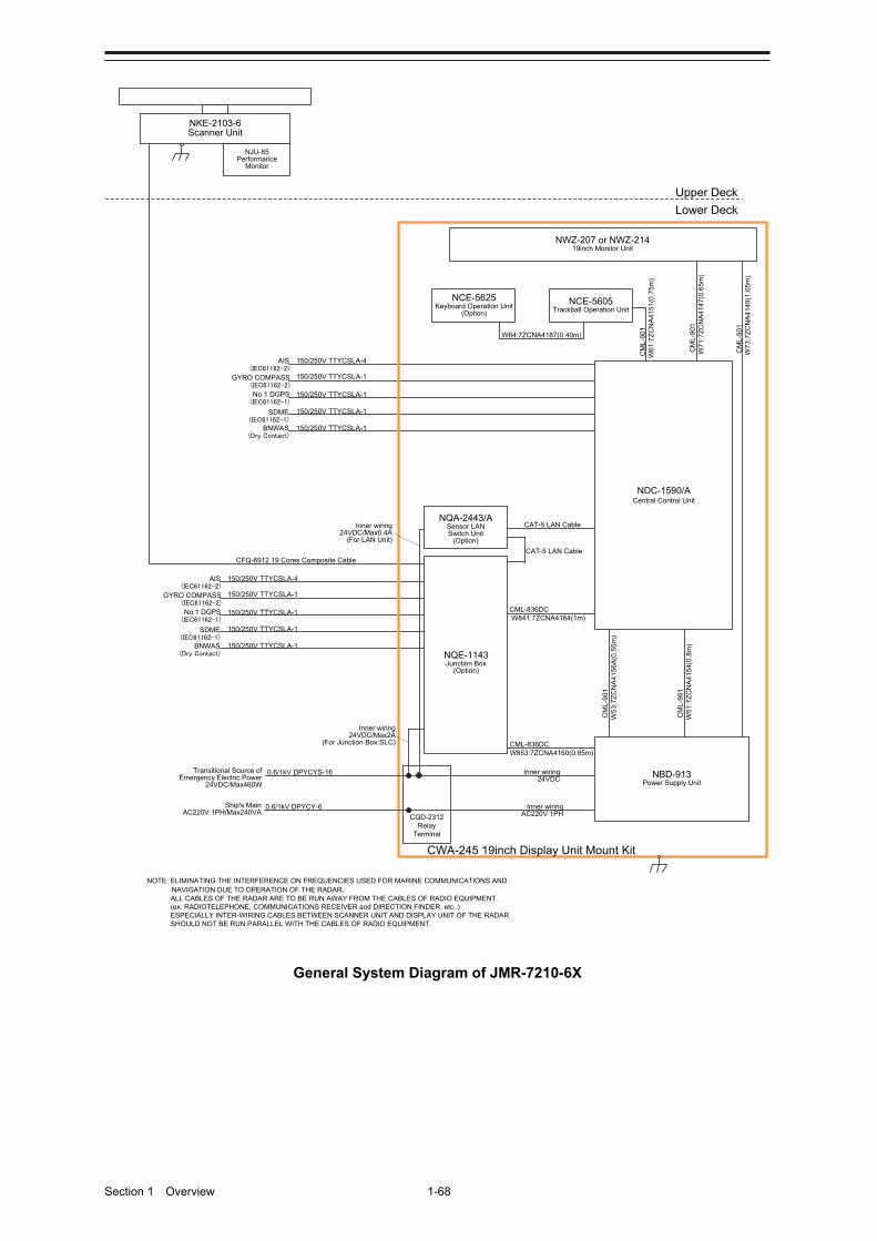
Section 1 Overview 1-68
150/250V TTYCSLA-4AIS(IEC61162-2)
GYRO COMPASS(IEC61162-2)
No.1 DGPS(IEC61162-1)
SDME(IEC61162-1)
BNWAS(Dry Contact)
Upper Deck
Lower Deck
NKE-2103-6Scanner Unit
NJU-85Performance
Monitor
CFQ-6912 19 Cores Composite Cable
150/250V TTYCSLA-1
150/250V TTYCSLA-1
150/250V TTYCSLA-1
150/250V TTYCSLA-1
150/250V TTYCSLA-4AIS(IEC61162-2)
GYRO COMPASS(IEC61162-2)
No.1 DGPS(IEC61162-1)
SDME(IEC61162-1)
BNWAS(Dry Contact)
150/250V TTYCSLA-1
150/250V TTYCSLA-1
150/250V TTYCSLA-1
150/250V TTYCSLA-1
NOTE: ELIMINATING THE INTERFERENCE ON FREQUENCIES USED FOR MARINE COMMUNICATIONS AND NAVIGATION DUE TO OPERATION OF THE RADAR,ALL CABLES OF THE RADAR ARE TO BE RUN AWAY FROM THE CABLES OF RADIO EQUIPMENT.(ex. RADIOTELEPHONE, COMMUNICATIONS RECEIVER and DIRECTION FINDER. etc..)ESPECIALLY INTER-WIRING CABLES BETWEEN SCANNER UNIT AND DISPLAY UNIT OF THE RADAR SHOULD NOT BE RUN PARALLEL WITH THE CABLES OF RADIO EQUIPMENT.
CAT-5 LAN Cable
NQE-1143Junction Box
(Option)
NCE-5605Trackball Operation Unit
NBD-913Power Supply Unit
NWZ-207 or NWZ-21419inch Monitor Unit
CM
L-90
1
W71
:7Z
CN
A4
147(
0.6
5m)
CM
L-9
01
W61
:7Z
CN
A41
51(0
.75
m)
CM
L-9
01
W7
3:7
ZC
NA
414
9(1
.05
m)
NCE-5625Keyboard Operation Unit
(Option)
W64:7ZCNA4187(0.40m)
CWA-245 19inch Display Unit Mount Kit
NQA-2443/ASensor LAN Switch Unit
(Option)
CAT-5 LAN Cable
NDC-1590/ACentral Control Unit
CM
L-90
1W
53:7
ZC
NA
415
6A(0
.55
m)
CM
L-90
1W
51:7
ZC
NA
415
4(0.
8m)
Inner wiring24VDC/Max2A
(For Junction Box:SLC)
Inner wiring24VDC/Max0.4A
(For LAN Unit)
CQD-2312Relay
Terminal
Transitional Source ofEmergency Electric Power
24VDC/Max460W
0.6/1kV DPYCYS-16
0.6/1kV DPYCY-6Ship's MainAC220V 1PH/Max240VA
Inner wiring24VDC
Inner wiringAC220V 1PH
CML-836DCW853:7ZCNA4160(0.85m)
CML-836DCW841:7ZCNA4164(1m)
General System Diagram of JMR-7210-6X

1-69 Section 1 Overview
1
2
3
4
5
6
7
8
9
10
11
12
13
14
15
16
17
18
19
20
21
22
23
24
25
26
27
付録
General System Diagram of JMR-7210-6XH
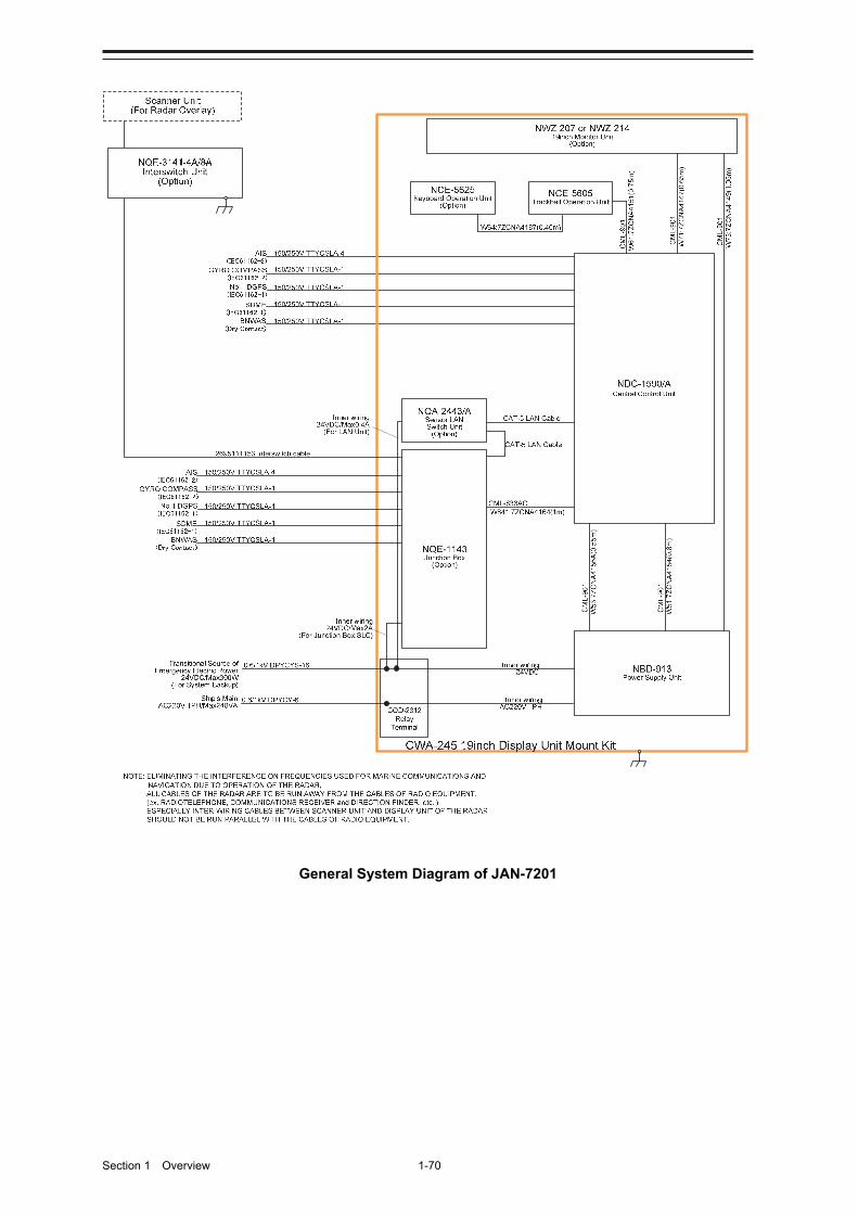
Section 1 Overview 1-70
General System Diagram of JAN-7201
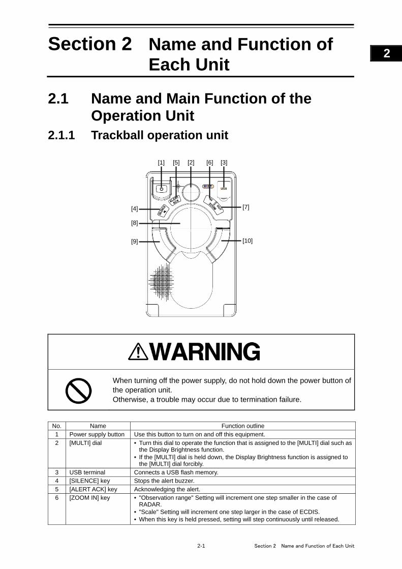
2-1 Section 2 Name and Function of Each Unit
1
2
3
4
5
6
7
8
9
10
11
12
13
14
15
16
17
18
19
20
21
22
23
24
25
APP A
APP B
1
Section 2 Name and Function of Each Unit
2.1 Name and Main Function of the Operation Unit
2.1.1 Trackball operation unit
When turning off the power supply, do not hold down the power button of the operation unit. Otherwise, a trouble may occur due to termination failure.
No. Name Function outline 1 Power supply button Use this button to turn on and off this equipment.
2 [MULTI] dial • Turn this dial to operate the function that is assigned to the [MULTI] dial such as the Display Brightness function.
• If the [MULTI] dial is held down, the Display Brightness function is assigned to the [MULTI] dial forcibly.
3 USB terminal Connects a USB flash memory. 4 [SILENCE] key Stops the alert buzzer. 5 [ALERT ACK] key Acknowledging the alert. 6 [ZOOM IN] key • "Observation range" Setting will increment one step smaller in the case of
RADAR. • "Scale" Setting will increment one step larger in the case of ECDIS. • When this key is held pressed, setting will step continuously until released.
[1] [2] [3] [6]
[7] [4]
[5]
[8]
[9] [10]
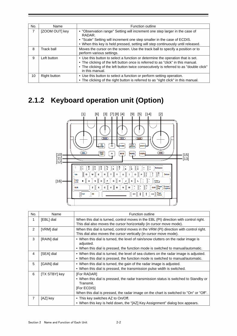
Section 2 Name and Function of Each Unit 2-2
No. Name Function outline 7 [ZOOM OUT] key • "Observation range" Setting will increment one step larger in the case of
RADAR. • "Scale" Setting will increment one step smaller in the case of ECDIS. • When this key is held pressed, setting will step continuously until released.
8 Track ball Moves the cursor on the screen. Use the track ball to specify a position or to perform various settings.
9 Left button • Use this button to select a function or determine the operation that is set. • The clicking of the left button once is referred to as "click" in this manual. • The clicking of the left button twice consecutively is referred to as "double click"
in this manual. 10 Right button • Use this button to select a function or perform setting operation.
• The clicking of the right button is referred to as "right click" in this manual.
2.1.2 Keyboard operation unit (Option)
No. Name Function outline
1 [EBL] dial When this dial is turned, control moves in the EBL (PI) direction with control right. This dial also moves the cursor horizontally (in cursor move mode).
2 [VRM] dial When this dial is turned, control moves in the VRM (PI) direction with control right. This dial also moves the cursor vertically (in cursor move mode).
3 [RAIN] dial • When this dial is turned, the level of rain/snow clutters on the radar image is adjusted.
• When this dial is pressed, the function mode is switched to manual/automatic.
4 [SEA] dial • When this dial is turned, the level of sea clutters on the radar image is adjusted. • When this dial is pressed, the function mode is switched to manual/automatic.
5 [GAIN] dial • When this dial is turned, the gain of the radar image is adjusted. • When this dial is pressed, the transmission pulse width is switched.
6 [TX STBY] key [For RADAR] • When this dial is pressed, the radar transmission status is switched to Standby or
Transmit. [For ECDIS] When this dial is pressed, the radar image on the chart is switched to "On" or "Off".
7 [AZ] key • This key switches AZ to On/Off. • When this key is held down, the “[AZ] Key Assignment” dialog box appears.
[1] [3]
[15] [10]
[2] [4] [5] [6] [9] [8] [14]
[13] [12]
[7]
[11]
[16]
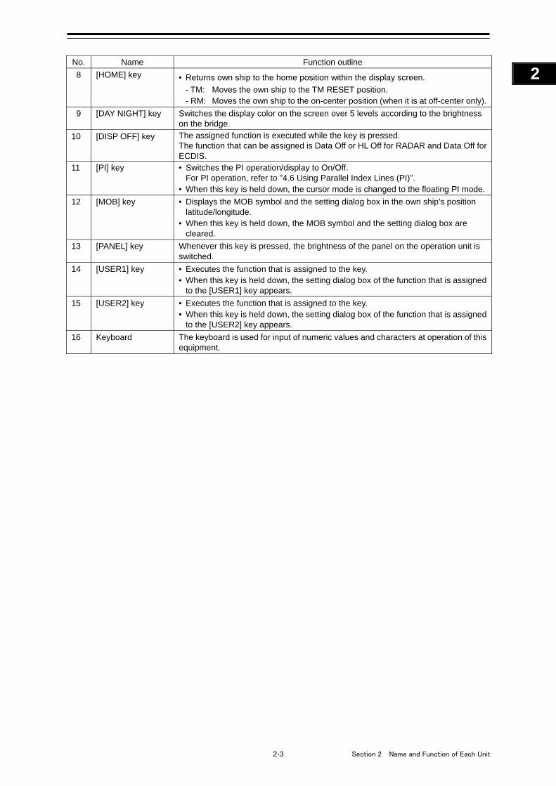
2-3 Section 2 Name and Function of Each Unit
1
2
3
4
5
6
7
8
9
10
11
12
13
14
15
16
17
18
19
20
21
22
23
24
25
APP A
APP B
1
No. Name Function outline
8 [HOME] key • Returns own ship to the home position within the display screen.
- TM: Moves the own ship to the TM RESET position. - RM: Moves the own ship to the on-center position (when it is at off-center only).
9 [DAY NIGHT] key Switches the display color on the screen over 5 levels according to the brightness on the bridge.
10 [DISP OFF] key The assigned function is executed while the key is pressed. The function that can be assigned is Data Off or HL Off for RADAR and Data Off for ECDIS.
11 [PI] key • Switches the PI operation/display to On/Off. For PI operation, refer to "4.6 Using Parallel Index Lines (PI)".
• When this key is held down, the cursor mode is changed to the floating PI mode.
12 [MOB] key • Displays the MOB symbol and the setting dialog box in the own ship’s position latitude/longitude.
• When this key is held down, the MOB symbol and the setting dialog box are cleared.
13 [PANEL] key Whenever this key is pressed, the brightness of the panel on the operation unit is switched.
14 [USER1] key • Executes the function that is assigned to the key. • When this key is held down, the setting dialog box of the function that is assigned
to the [USER1] key appears.
15 [USER2] key • Executes the function that is assigned to the key. • When this key is held down, the setting dialog box of the function that is assigned
to the [USER2] key appears.
16 Keyboard The keyboard is used for input of numeric values and characters at operation of this equipment.
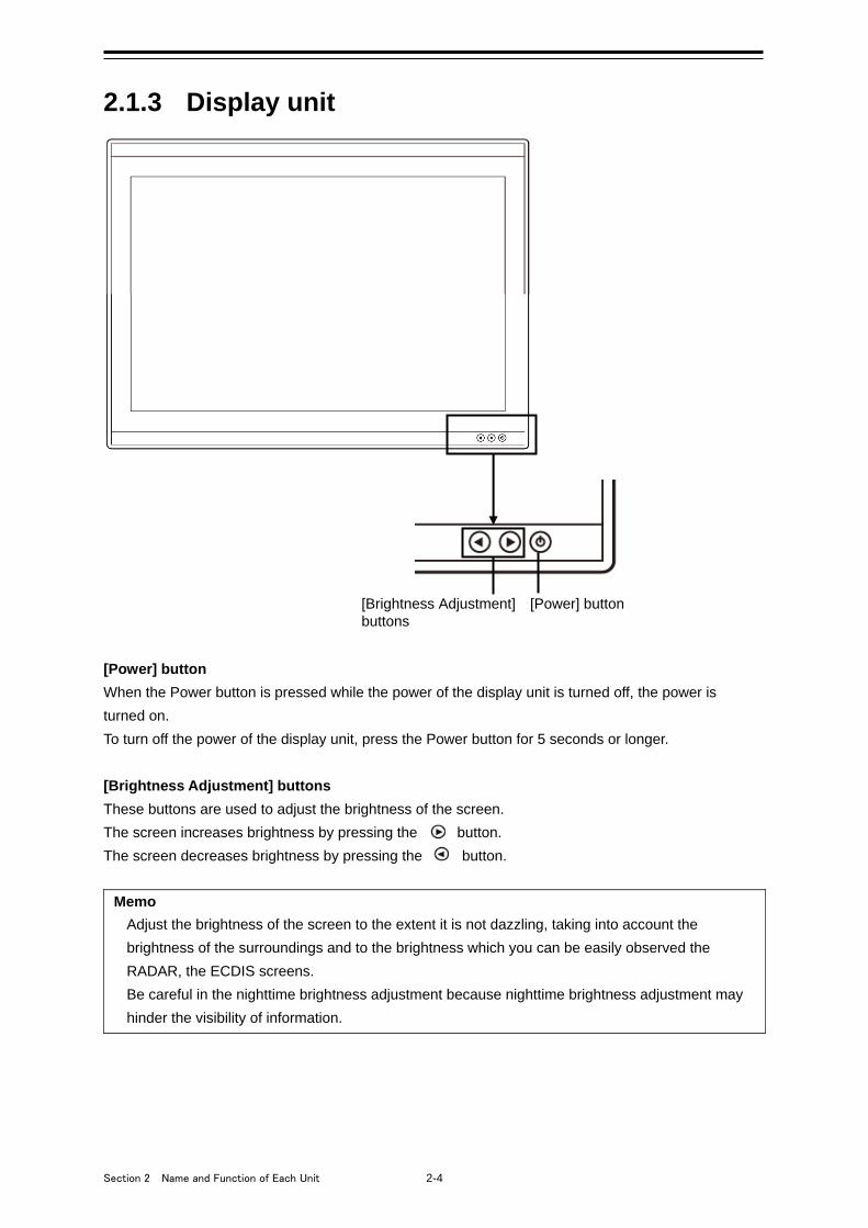
Section 2 Name and Function of Each Unit 2-4
2.1.3 Display unit
[Power] button
When the Power button is pressed while the power of the display unit is turned off, the power is
turned on.
To turn off the power of the display unit, press the Power button for 5 seconds or longer.
[Brightness Adjustment] buttons
These buttons are used to adjust the brightness of the screen.
The screen increases brightness by pressing the button.
The screen decreases brightness by pressing the button.
Memo
Adjust the brightness of the screen to the extent it is not dazzling, taking into account the
brightness of the surroundings and to the brightness which you can be easily observed the
RADAR, the ECDIS screens.
Be careful in the nighttime brightness adjustment because nighttime brightness adjustment may
hinder the visibility of information.
[Brightness Adjustment] [Power] button buttons
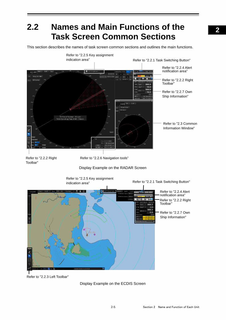
2-5 Section 2 Name and Function of Each Unit
1
2
3
4
5
6
7
8
9
10
11
12
13
14
15
16
17
18
19
20
21
22
23
24
25
APP A
APP B
1
2.2 Names and Main Functions of the Task Screen Common Sections
This section describes the names of task screen common sections and outlines the main functions.
Display Example on the RADAR Screen
Display Example on the ECDIS Screen
Refer to "2.2.6 Navigation tools"
Refer to "2.2.4 Alert notification area"
Refer to "2.2.2 Right Toolbar"
Refer to "2.2.1 Task Switching Button"
Refer to "2.2.5 Key assignment indication area"
Refer to "2.2.7 Own Ship Information"
Refer to "2.3 Common Information Window"
Refer to "2.2.2 Right Toolbar"
Refer to "2.2.1 Task Switching Button" Refer to "2.2.5 Key assignment indication area"
Refer to "2.2.4 Alert notification area"
Refer to "2.2.3 Left Toolbar"
Refer to "2.2.7 Own Ship Information"
Refer to "2.2.2 Right Toolbar"
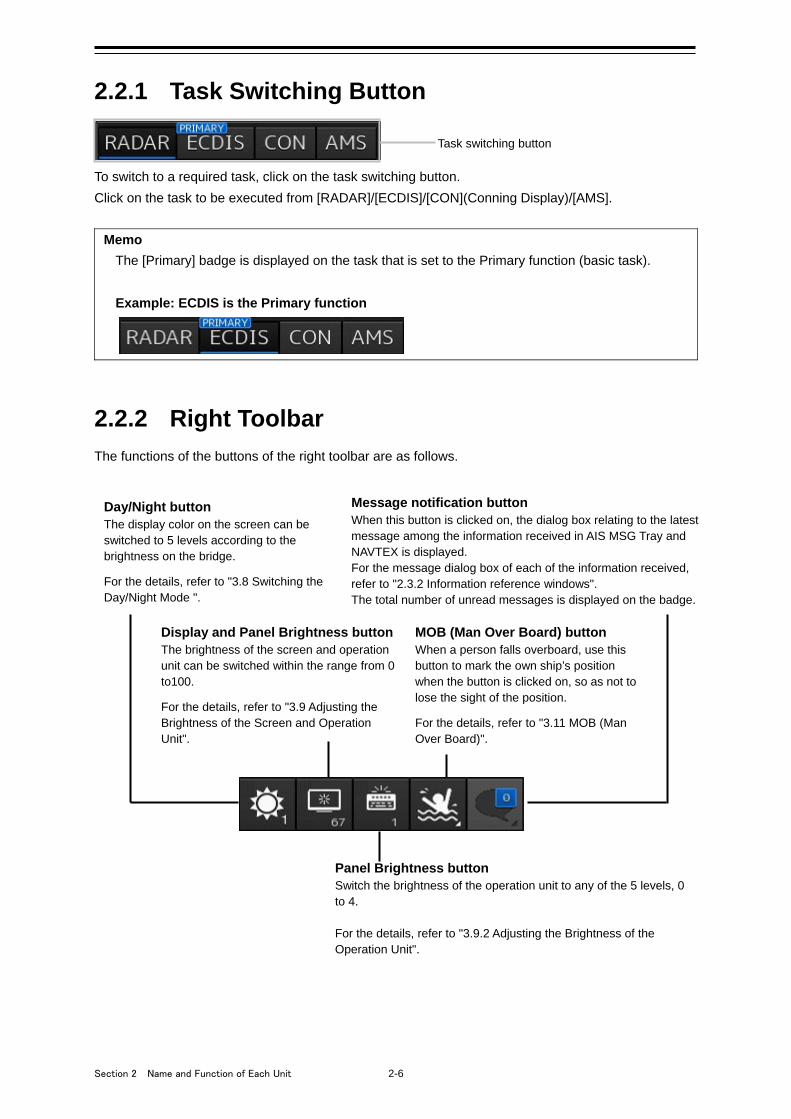
Section 2 Name and Function of Each Unit 2-6
2.2.1 Task Switching Button
To switch to a required task, click on the task switching button.
Click on the task to be executed from [RADAR]/[ECDIS]/[CON](Conning Display)/[AMS].
Memo
The [Primary] badge is displayed on the task that is set to the Primary function (basic task).
Example: ECDIS is the Primary function
2.2.2 Right Toolbar
The functions of the buttons of the right toolbar are as follows.
Day/Night button The display color on the screen can be switched to 5 levels according to the brightness on the bridge. For the details, refer to "3.8 Switching the Day/Night Mode ".
Display and Panel Brightness button The brightness of the screen and operation unit can be switched within the range from 0 to100. For the details, refer to "3.9 Adjusting the Brightness of the Screen and Operation Unit".
MOB (Man Over Board) button When a person falls overboard, use this button to mark the own ship’s position when the button is clicked on, so as not to lose the sight of the position. For the details, refer to "3.11 MOB (Man Over Board)".
Message notification button When this button is clicked on, the dialog box relating to the latest message among the information received in AIS MSG Tray and NAVTEX is displayed. For the message dialog box of each of the information received, refer to "2.3.2 Information reference windows". The total number of unread messages is displayed on the badge.
Panel Brightness button Switch the brightness of the operation unit to any of the 5 levels, 0 to 4. For the details, refer to "3.9.2 Adjusting the Brightness of the Operation Unit".
Task switching button
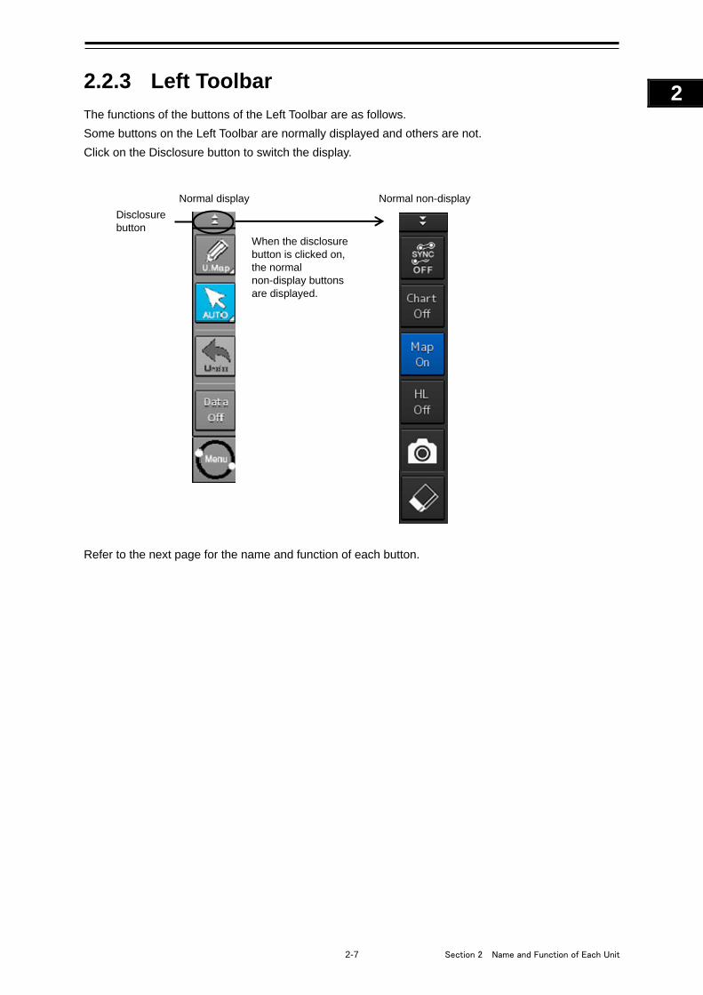
2-7 Section 2 Name and Function of Each Unit
1
2
3
4
5
6
7
8
9
10
11
12
13
14
15
16
17
18
19
20
21
22
23
24
25
APP A
APP B
1
2.2.3 Left Toolbar
The functions of the buttons of the Left Toolbar are as follows.
Some buttons on the Left Toolbar are normally displayed and others are not.
Click on the Disclosure button to switch the display.
Refer to the next page for the name and function of each button.
When the disclosure button is clicked on, the normal non-display buttons are displayed.
Disclosure button
Normal display Normal non-display
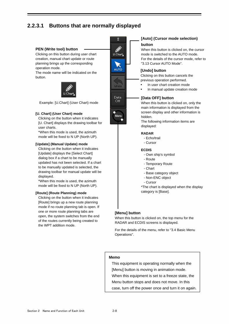
Section 2 Name and Function of Each Unit 2-8
2.2.3.1 Buttons that are normally displayed
[Auto] (Cursor mode selection)
button When this button is clicked on, the cursor mode is switched to the AUTO mode. For the details of the cursor mode, refer to "3.13 Cursor AUTO Mode".
PEN (Write tool) button Clicking on this button during user chart creation, manual chart update or route planning brings up the corresponding operation mode. The mode name will be indicated on the button.
Example: [U.Chart] (User Chart) mode [U. Chart] (User Chart) mode
Clicking on the button when it indicates [U. Chart] displays the drawing toolbar for user charts. *When this mode is used, the azimuth mode will be fixed to N UP (North UP).
[Update] (Manual Update) mode
Clicking on the button when it indicates [Update] displays the [Select Chart] dialog box if a chart to be manually updated has not been selected. If a chart to be manually updated is selected, the drawing toolbar for manual update will be displayed. *When this mode is used, the azimuth mode will be fixed to N UP (North UP).
[Route] (Route Planning) mode
Clicking on the button when it indicates [Route] brings up a new route planning mode if no route planning tab is open. If one or more route planning tabs are open, the system switches from the end of the routes currently being created to the WPT addition mode.
[Undo] button Clicking on this button cancels the previous operation performed. • In user chart creation mode • In manual update creation mode
[Data OFF] button When this button is clicked on, only the main information is displayed from the screen display and other information is hidden. The following information items are displayed: RADAR
- Echo/trail - Cursor
ECDIS
- Own ship’s symbol - Route - Temporary Route - Chart - Base category object - Non-ENC object - Cursor
*The chart is displayed when the display category is [Base].
[Menu] button When this button is clicked on, the top menu for the RADAR and ECDIS screens is displayed. For the details of the menu, refer to "3.4 Basic Menu Operations".
Memo This equipment is operating normally when the
[Menu] button is moving in animation mode.
When this equipment is set to a freeze state, the
Menu button stops and does not move. In this
case, turn off the power once and turn it on again.
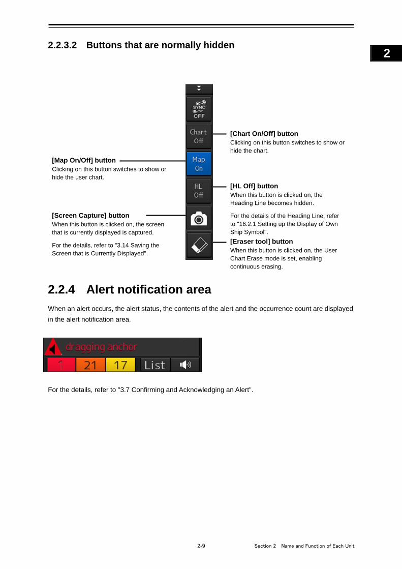
2-9 Section 2 Name and Function of Each Unit
1
2
3
4
5
6
7
8
9
10
11
12
13
14
15
16
17
18
19
20
21
22
23
24
25
APP A
APP B
1
2.2.3.2 Buttons that are normally hidden
2.2.4 Alert notification area
When an alert occurs, the alert status, the contents of the alert and the occurrence count are displayed
in the alert notification area.
For the details, refer to "3.7 Confirming and Acknowledging an Alert".
[Screen Capture] button When this button is clicked on, the screen that is currently displayed is captured. For the details, refer to "3.14 Saving the Screen that is Currently Displayed".
[Chart On/Off] button Clicking on this button switches to show or hide the chart.
[HL Off] button When this button is clicked on, the Heading Line becomes hidden. For the details of the Heading Line, refer to "16.2.1 Setting up the Display of Own Ship Symbol". [Eraser tool] button When this button is clicked on, the User Chart Erase mode is set, enabling continuous erasing.
[Map On/Off] button Clicking on this button switches to show or hide the user chart.
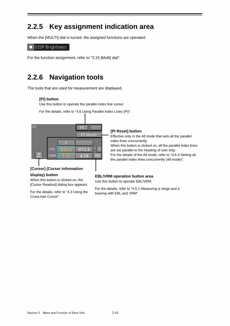
Section 2 Name and Function of Each Unit 2-10
2.2.5 Key assignment indication area
When the [MULTI] dial is turned, the assigned functions are operated.
For the function assignment, refer to "3.15 [Multi] dial".
2.2.6 Navigation tools
The tools that are used for measurement are displayed.
[PI] button Use this button to operate the parallel index line cursor. For the details, refer to "4.6 Using Parallel Index Lines (PI)".
[Cursor] (Cursor information
display) button When this button is clicked on, the [Cursor Readout] dialog box appears. For the details, refer to "4.3 Using the Cross-hair Cursor".
EBL/VRM operation button area Use this button to operate EBL/VRM. For the details, refer to "4.5.1 Measuring a range and a bearing with EBL and VRM"
[PI Reset] button Effective only in the All mode that sets all the parallel index lines concurrently. When this button is clicked on, all the parallel index lines are set parallel to the heading of own ship. For the details of the All mode, refer to "4.6.3 Setting all the parallel index lines concurrently (All mode)".
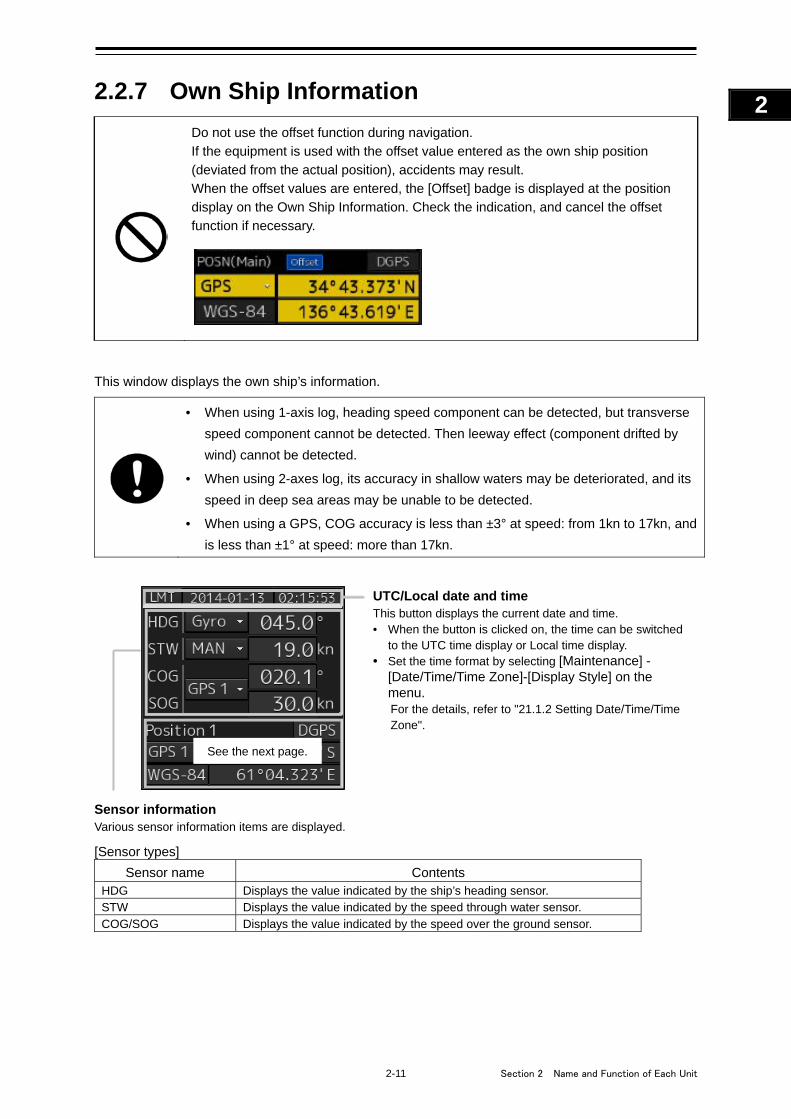
2-11 Section 2 Name and Function of Each Unit
1
2
3
4
5
6
7
8
9
10
11
12
13
14
15
16
17
18
19
20
21
22
23
24
25
APP A
APP B
1
2.2.7 Own Ship Information
Do not use the offset function during navigation.
If the equipment is used with the offset value entered as the own ship position
(deviated from the actual position), accidents may result. When the offset values are entered, the [Offset] badge is displayed at the position display on the Own Ship Information. Check the indication, and cancel the offset
function if necessary.
This window displays the own ship’s information.
• When using 1-axis log, heading speed component can be detected, but transverse
speed component cannot be detected. Then leeway effect (component drifted by
wind) cannot be detected.
• When using 2-axes log, its accuracy in shallow waters may be deteriorated, and its
speed in deep sea areas may be unable to be detected.
• When using a GPS, COG accuracy is less than ±3° at speed: from 1kn to 17kn, and
is less than ±1° at speed: more than 17kn.
Sensor information Various sensor information items are displayed. [Sensor types]
Sensor name Contents HDG Displays the value indicated by the ship’s heading sensor. STW Displays the value indicated by the speed through water sensor. COG/SOG Displays the value indicated by the speed over the ground sensor.
UTC/Local date and time This button displays the current date and time. • When the button is clicked on, the time can be switched
to the UTC time display or Local time display. • Set the time format by selecting [Maintenance] -
[Date/Time/Time Zone]-[Display Style] on the menu. For the details, refer to "21.1.2 Setting Date/Time/Time Zone".
See the next page.
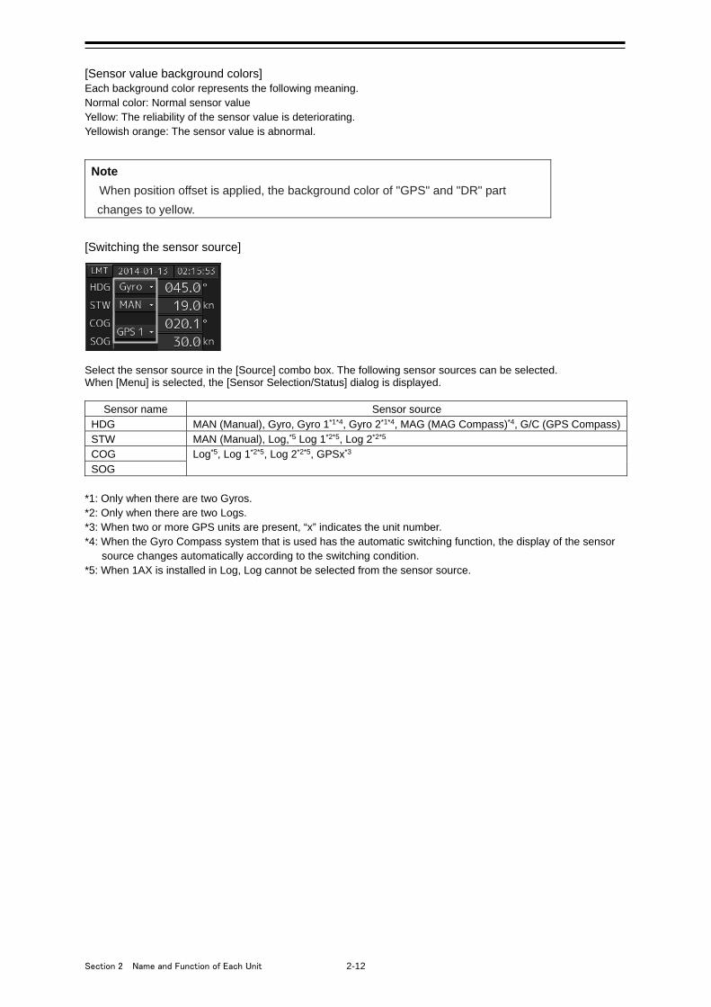
Section 2 Name and Function of Each Unit 2-12
[Sensor value background colors] Each background color represents the following meaning. Normal color: Normal sensor value Yellow: The reliability of the sensor value is deteriorating. Yellowish orange: The sensor value is abnormal.
Note
When position offset is applied, the background color of "GPS" and "DR" part
changes to yellow.
[Switching the sensor source]
Select the sensor source in the [Source] combo box. The following sensor sources can be selected. When [Menu] is selected, the [Sensor Selection/Status] dialog is displayed.
Sensor name Sensor source HDG MAN (Manual), Gyro, Gyro 1*1*4, Gyro 2*1*4, MAG (MAG Compass)*4, G/C (GPS Compass) STW MAN (Manual), Log,*5 Log 1*2*5, Log 2*2*5 COG Log*5, Log 1*2*5, Log 2*2*5, GPSx*3 SOG
*1: Only when there are two Gyros. *2: Only when there are two Logs. *3: When two or more GPS units are present, “x” indicates the unit number. *4: When the Gyro Compass system that is used has the automatic switching function, the display of the sensor
source changes automatically according to the switching condition. *5: When 1AX is installed in Log, Log cannot be selected from the sensor source.
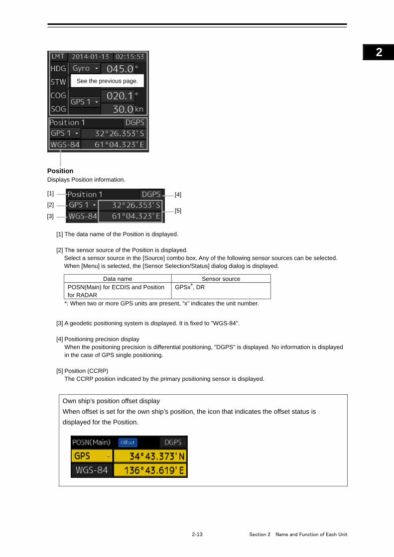
2-13 Section 2 Name and Function of Each Unit
1
2
3
4
5
6
7
8
9
10
11
12
13
14
15
16
17
18
19
20
21
22
23
24
25
APP A
APP B
1
[1] The data name of the Position is displayed. [2] The sensor source of the Position is displayed.
Select a sensor source in the [Source] combo box. Any of the following sensor sources can be selected. When [Menu] is selected, the [Sensor Selection/Status] dialog dialog is displayed.
Data name Sensor source
POSN(Main) for ECDIS and Position for RADAR
GPSx*, DR
*: When two or more GPS units are present, “x” indicates the unit number.
[3] A geodetic positioning system is displayed. It is fixed to "WGS-84".
[4] Positioning precision display When the positioning precision is differential positioning, "DGPS" is displayed. No information is displayed
in the case of GPS single positioning.
[5] Position (CCRP) The CCRP position indicated by the primary positioning sensor is displayed.
Own ship’s position offset display
When offset is set for the own ship’s position, the icon that indicates the offset status is
displayed for the Position.
[1]
[2]
[3]
[4]
[5]
See the previous page.
Position Displays Position information.
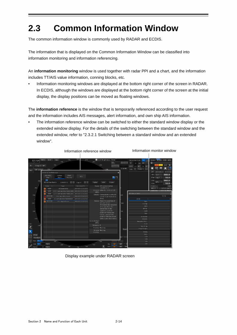
Section 2 Name and Function of Each Unit 2-14
2.3 Common Information Window The common information window is commonly used by RADAR and ECDIS.
The information that is displayed on the Common Information Window can be classified into
information monitoring and information referencing.
An information monitoring window is used together with radar PPI and a chart, and the information
includes TT/AIS value information, conning blocks, etc.
• Information monitoring windows are displayed at the bottom right corner of the screen in RADAR.
In ECDIS, although the windows are displayed at the bottom right corner of the screen at the initial
display, the display positions can be moved as floating windows.
The information reference is the window that is temporarily referenced according to the user request
and the information includes AIS messages, alert information, and own ship AIS information.
• The information reference window can be switched to either the standard window display or the
extended window display. For the details of the switching between the standard window and the
extended window, refer to "2.3.2.1 Switching between a standard window and an extended
window".
Display example under RADAR screen
Information reference window Information monitor window
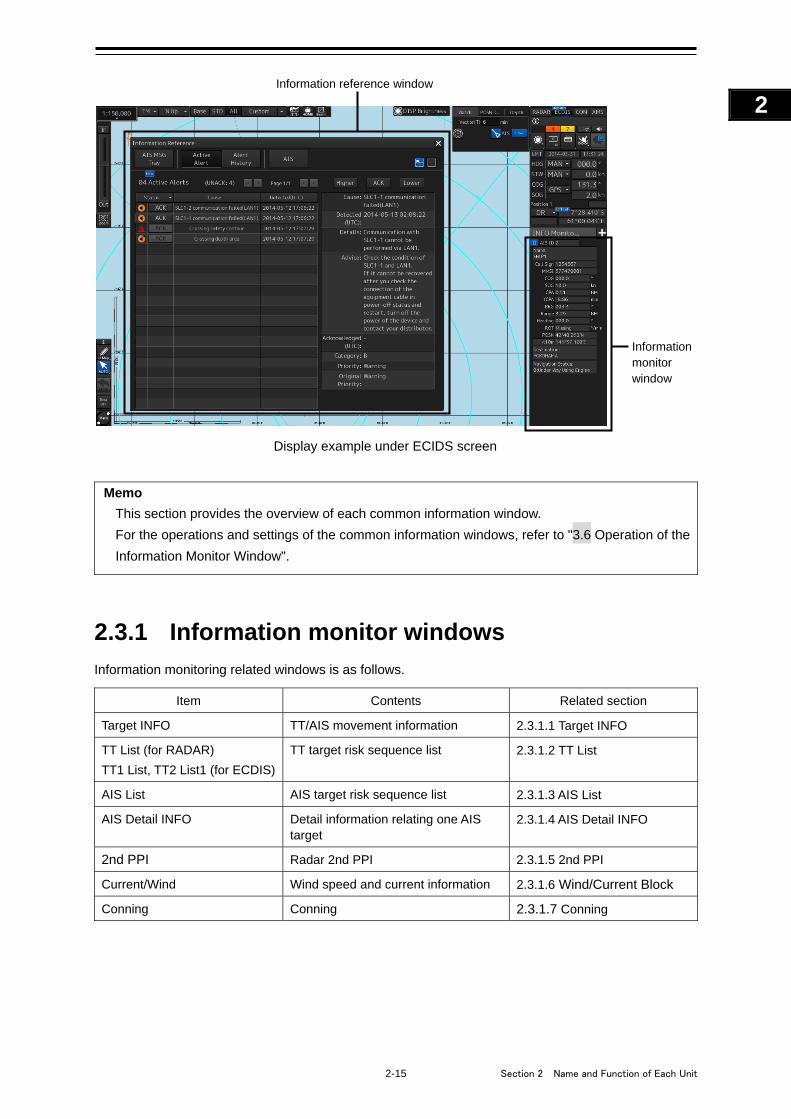
2-15 Section 2 Name and Function of Each Unit
1
2
3
4
5
6
7
8
9
10
11
12
13
14
15
16
17
18
19
20
21
22
23
24
25
APP A
APP B
1
Display example under ECIDS screen
Memo
This section provides the overview of each common information window.
For the operations and settings of the common information windows, refer to "3.6 Operation of the
Information Monitor Window".
2.3.1 Information monitor windows
Information monitoring related windows is as follows.
Item Contents Related section
Target INFO TT/AIS movement information 2.3.1.1 Target INFO
TT List (for RADAR)
TT1 List, TT2 List1 (for ECDIS)
TT target risk sequence list 2.3.1.2 TT List
AIS List AIS target risk sequence list 2.3.1.3 AIS List
AIS Detail INFO Detail information relating one AIS target
2.3.1.4 AIS Detail INFO
2nd PPI Radar 2nd PPI 2.3.1.5 2nd PPI
Current/Wind Wind speed and current information 2.3.1.6 Wind/Current Block
Conning Conning 2.3.1.7 Conning
Information reference window
Information monitor window
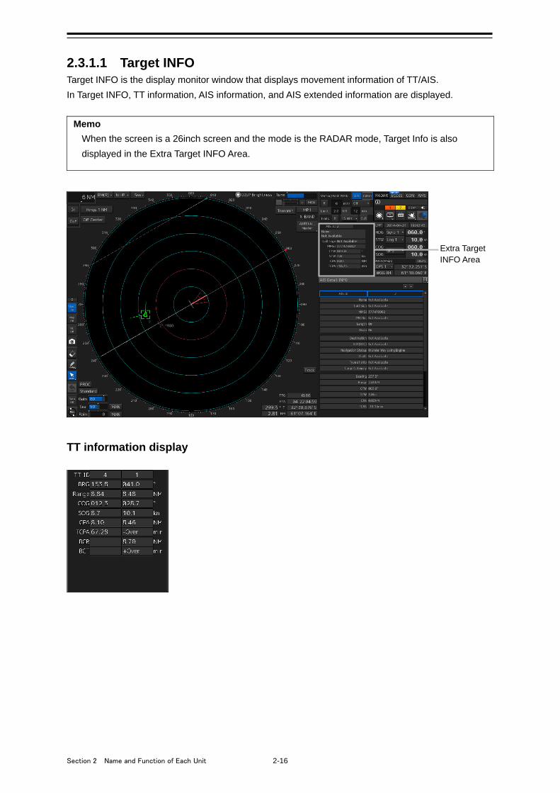
Section 2 Name and Function of Each Unit 2-16
2.3.1.1 Target INFO Target INFO is the display monitor window that displays movement information of TT/AIS.
In Target INFO, TT information, AIS information, and AIS extended information are displayed.
Memo
When the screen is a 26inch screen and the mode is the RADAR mode, Target Info is also
displayed in the Extra Target INFO Area.
TT information display
Extra Target INFO Area
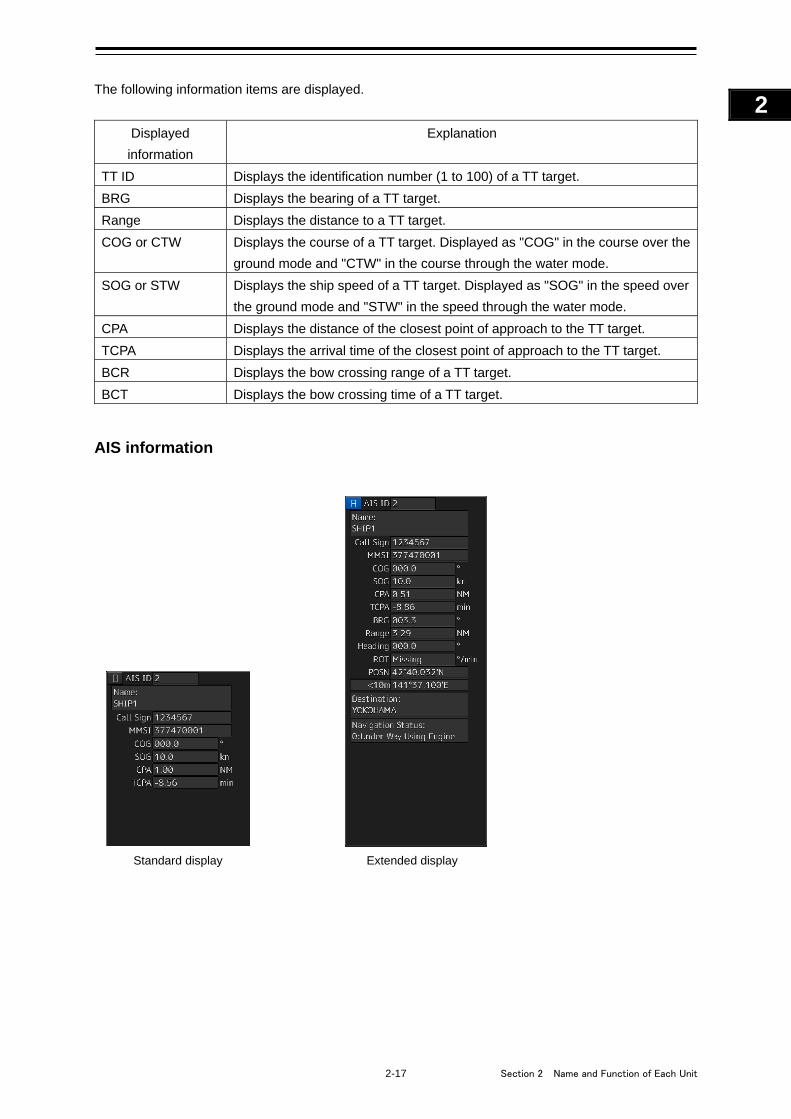
2-17 Section 2 Name and Function of Each Unit
1
2
3
4
5
6
7
8
9
10
11
12
13
14
15
16
17
18
19
20
21
22
23
24
25
APP A
APP B
1
The following information items are displayed.
Displayed
information
Explanation
TT ID Displays the identification number (1 to 100) of a TT target.
BRG Displays the bearing of a TT target.
Range Displays the distance to a TT target.
COG or CTW Displays the course of a TT target. Displayed as "COG" in the course over the
ground mode and "CTW" in the course through the water mode.
SOG or STW Displays the ship speed of a TT target. Displayed as "SOG" in the speed over
the ground mode and "STW" in the speed through the water mode.
CPA Displays the distance of the closest point of approach to the TT target.
TCPA Displays the arrival time of the closest point of approach to the TT target.
BCR Displays the bow crossing range of a TT target.
BCT Displays the bow crossing time of a TT target.
AIS information
Standard display Extended display
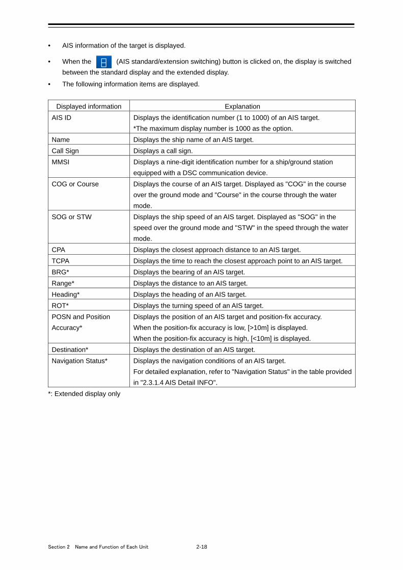
Section 2 Name and Function of Each Unit 2-18
• AIS information of the target is displayed.
• When the (AIS standard/extension switching) button is clicked on, the display is switched
between the standard display and the extended display.
• The following information items are displayed.
Displayed information Explanation
AIS ID Displays the identification number (1 to 1000) of an AIS target.
*The maximum display number is 1000 as the option.
Name Displays the ship name of an AIS target.
Call Sign Displays a call sign.
MMSI Displays a nine-digit identification number for a ship/ground station
equipped with a DSC communication device.
COG or Course Displays the course of an AIS target. Displayed as "COG" in the course
over the ground mode and "Course" in the course through the water
mode.
SOG or STW Displays the ship speed of an AIS target. Displayed as "SOG" in the
speed over the ground mode and "STW" in the speed through the water
mode.
CPA Displays the closest approach distance to an AIS target.
TCPA Displays the time to reach the closest approach point to an AIS target.
BRG* Displays the bearing of an AIS target.
Range* Displays the distance to an AIS target.
Heading* Displays the heading of an AIS target.
ROT* Displays the turning speed of an AIS target.
POSN and Position
Accuracy*
Displays the position of an AIS target and position-fix accuracy.
When the position-fix accuracy is low, [>10m] is displayed.
When the position-fix accuracy is high, [<10m] is displayed.
Destination* Displays the destination of an AIS target.
Navigation Status* Displays the navigation conditions of an AIS target.
For detailed explanation, refer to "Navigation Status" in the table provided
in "2.3.1.4 AIS Detail INFO".
*: Extended display only

2-19 Section 2 Name and Function of Each Unit
1
2
3
4
5
6
7
8
9
10
11
12
13
14
15
16
17
18
19
20
21
22
23
24
25
APP A
APP B
1
AIS SART information
AIS SART information is displayed by using an extended display.
Unlike the AIS information extended display, the following items are not displayed.
• Call Sign
• Destination
• (AIS standard/extension switching) button
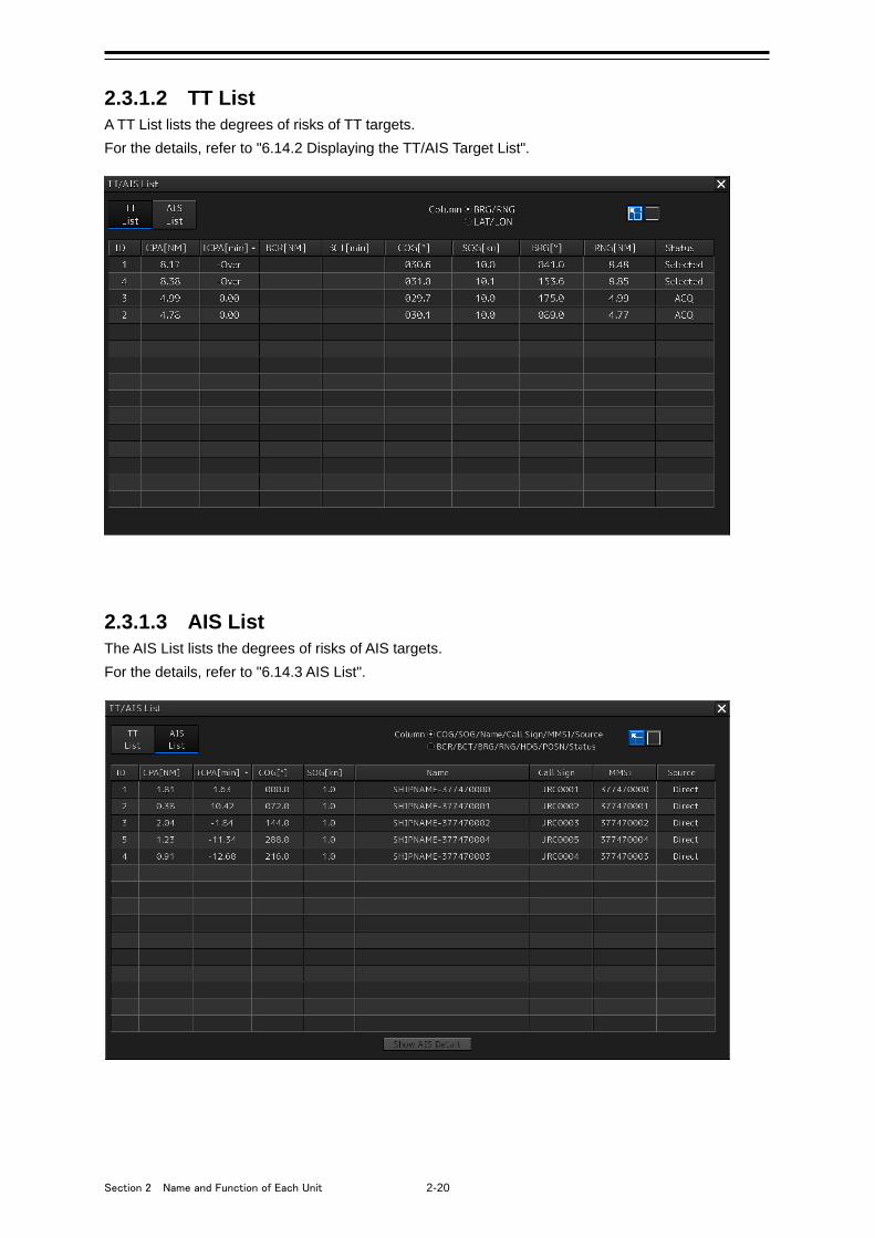
Section 2 Name and Function of Each Unit 2-20
2.3.1.2 TT List A TT List lists the degrees of risks of TT targets.
For the details, refer to "6.14.2 Displaying the TT/AIS Target List".
2.3.1.3 AIS List The AIS List lists the degrees of risks of AIS targets.
For the details, refer to "6.14.3 AIS List".
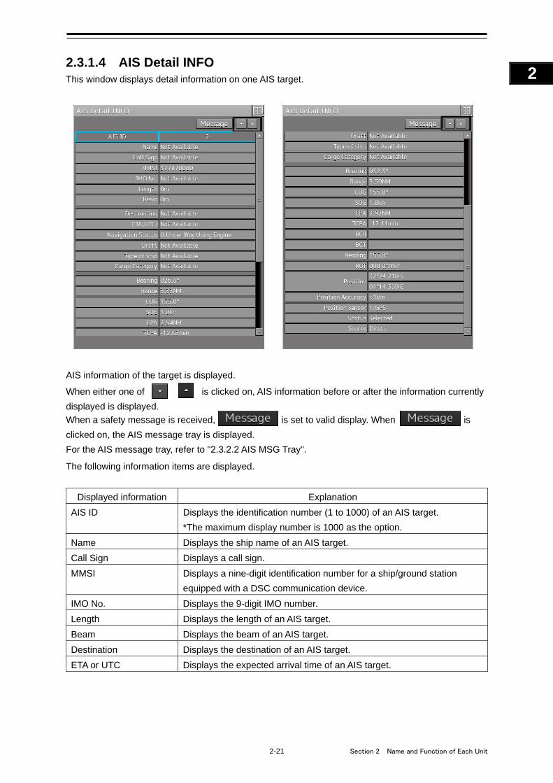
2-21 Section 2 Name and Function of Each Unit
1
2
3
4
5
6
7
8
9
10
11
12
13
14
15
16
17
18
19
20
21
22
23
24
25
APP A
APP B
1
2.3.1.4 AIS Detail INFO This window displays detail information on one AIS target.
AIS information of the target is displayed.
When either one of is clicked on, AIS information before or after the information currently
displayed is displayed.
When a safety message is received, is set to valid display. When
is
clicked on, the AIS message tray is displayed.
For the AIS message tray, refer to "2.3.2.2 AIS MSG Tray".
The following information items are displayed.
Displayed information Explanation
AIS ID Displays the identification number (1 to 1000) of an AIS target.
*The maximum display number is 1000 as the option.
Name Displays the ship name of an AIS target.
Call Sign Displays a call sign.
MMSI Displays a nine-digit identification number for a ship/ground station
equipped with a DSC communication device.
IMO No. Displays the 9-digit IMO number.
Length Displays the length of an AIS target.
Beam Displays the beam of an AIS target.
Destination Displays the destination of an AIS target.
ETA or UTC Displays the expected arrival time of an AIS target.
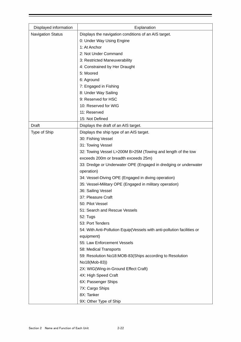
Section 2 Name and Function of Each Unit 2-22
Displayed information Explanation
Navigation Status Displays the navigation conditions of an AIS target.
0: Under Way Using Engine
1: At Anchor
2: Not Under Command
3: Restricted Maneuverability
4: Constrained by Her Draught
5: Moored
6: Aground
7: Engaged in Fishing
8: Under Way Sailing
9: Reserved for HSC
10: Reserved for WIG
11: Reserved
15: Not Defined
Draft Displays the draft of an AIS target.
Type of Ship Displays the ship type of an AIS target.
30: Fishing Vessel
31: Towing Vessel
32: Towing Vessel L>200M B>25M (Towing and length of the tow
exceeds 200m or breadth exceeds 25m)
33: Dredge or Underwater OPE (Engaged in dredging or underwater
operation)
34: Vessel-Diving OPE (Engaged in diving operation)
35: Vessel-Military OPE (Engaged in military operation)
36: Sailing Vessel
37: Pleasure Craft
50: Pilot Vessel
51: Search and Rescue Vessels
52: Tugs
53: Port Tenders
54: With Anti-Pollution Equip(Vessels with anti-pollution facilities or
equipment)
55: Law Enforcement Vessels
58: Medical Transports
59: Resolution No18:MOB-83(Ships according to Resolution
No18(Mob-83))
2X: WIG(Wing-in-Ground Effect Craft)
4X: High Speed Craft
6X: Passenger Ships
7X: Cargo Ships
8X: Tanker
9X: Other Type of Ship
2-23 Section 2 Name and Function of Each Unit
1
2
3
4
5
6
7
8
9
10
11
12
13
14
15
16
17
18
19
20
21
22
23
24
25
APP A
APP B
1
Displayed information Explanation
Cargo Category When the setting of the type of a ship is
2X, 4X, 6X, 7X, 8X or 9X, the digit shown at the end of the code
represents the cargo/condition.
X1 Category X(DG/HP/MP)
X2 Category Y(DG/HP/MP)
X3 Category Z(DG/HP/MP)
X4 Category OS(DG/HP/MP)
X9 No Additional Information
X0 All Ships of This Type
Bearing Displays the bearing of an AIS target.
Range Displays the distance to an AIS target.
COG Displays the course of an AIS target. Displayed as "COG" in the course
over the ground mode.
SOG Displays the ship speed of an AIS target. Displayed as "SOG" in the
speed over the ground mode.
CPA Displays the closest approach distance to an AIS target.
TCPA Displays the time to reach the closest approach point to an AIS target.
BCR Displays the bow crossing range of an AIS target.
BCT Displays the bow crossing time of an AIS target.
Heading Displays the heading of an AIS target.
ROT Displays the turning speed of an AIS target.
Position Displays the position of an AIS target.
Position Accuracy When the position-fix accuracy of an AIS target is low, [>10m] is
displayed.
When the position-fix accuracy of an AIS target is high, [<10m] is
displayed.
Position Sensor Displays the type of the position sensor used by an AIS target.
0: Not Defined
1: GPS
2: GLONASS
3: Combined GPS/GLONASS
4: Loran-C
5: Chayka
6: Integrated Navigation System
7: Surveyed
8: Galileo
15: Internal GNSS
Status Status of an AIS target
• Sleeping
• Active
• Lost
• Danger
• Selected
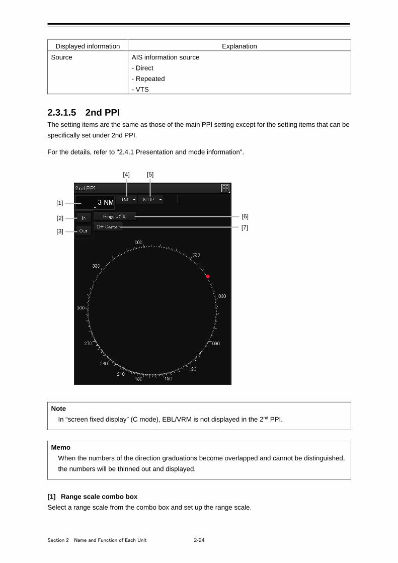
Section 2 Name and Function of Each Unit 2-24
Displayed information Explanation
Source AIS information source
- Direct
- Repeated
- VTS
2.3.1.5 2nd PPI The setting items are the same as those of the main PPI setting except for the setting items that can be
specifically set under 2nd PPI.
For the details, refer to "2.4.1 Presentation and mode information".
Note
In “screen fixed display” (C mode), EBL/VRM is not displayed in the 2nd PPI.
Memo
When the numbers of the direction graduations become overlapped and cannot be distinguished,
the numbers will be thinned out and displayed.
[1] Range scale combo box
Select a range scale from the combo box and set up the range scale.
[1] [2]
[3]
[5]
[6] [7]
[4]
2-25 Section 2 Name and Function of Each Unit
1
2
3
4
5
6
7
8
9
10
11
12
13
14
15
16
17
18
19
20
21
22
23
24
25
APP A
APP B
1
[2] [In] (Zoom In) button
When this button is clicked on, the display is zoomed in by one level from the range scale. When the
button is held down, the display is zoomed in continuously.
[3] [Out] (Zoom Out) button
When this button is clicked on, the display is zoomed out by one level from the range scale. When the
button is held down, the display is zoomed out continuously.
[4] Motion mode combo box
Select a motion mode from the combo box and set up the motion mode. The mode operates by linking
with the setting of the main PPI.
[5] Bearing mode combo box
Select a bearing mode from the combo box and set up the bearing mode The mode operates by linking
with the setting of the main PPI.
[6] Range rings display button
When this button is clicked on, the range rings display surrounding the own ship is set to On/Off.
[7] [Off Center] button
When this button is clicked on, the off-center of the own ship’s position (CCRP) is set to On/Off.
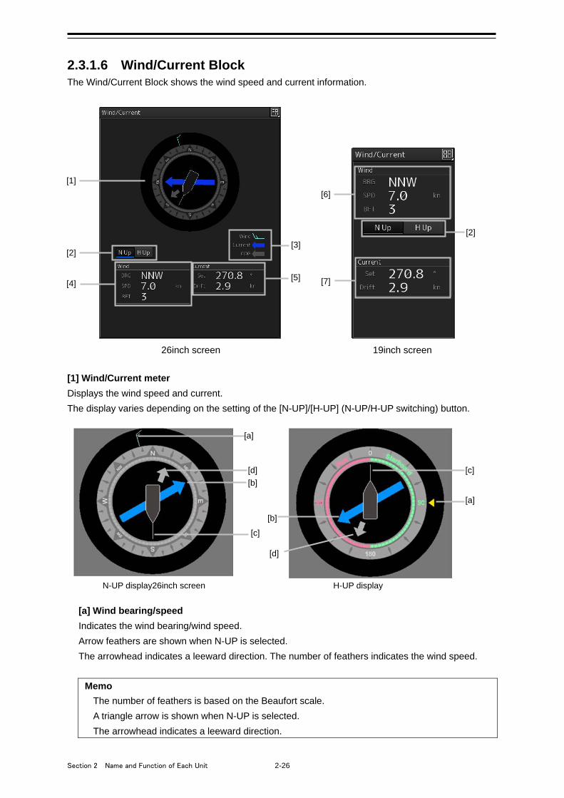
Section 2 Name and Function of Each Unit 2-26
2.3.1.6 Wind/Current Block The Wind/Current Block shows the wind speed and current information.
26inch screen 19inch screen
[1] Wind/Current meter
Displays the wind speed and current.
The display varies depending on the setting of the [N-UP]/[H-UP] (N-UP/H-UP switching) button.
[a] Wind bearing/speed
Indicates the wind bearing/wind speed.
Arrow feathers are shown when N-UP is selected.
The arrowhead indicates a leeward direction. The number of feathers indicates the wind speed.
Memo
The number of feathers is based on the Beaufort scale.
A triangle arrow is shown when N-UP is selected.
The arrowhead indicates a leeward direction.
[b]
[a]
[b]
[a]
[c]
[d] [c]
[d]
N-UP display26inch screen H-UP display
[1]
[2]
[4]
[3]
[5]
[6]
[2]
[7]
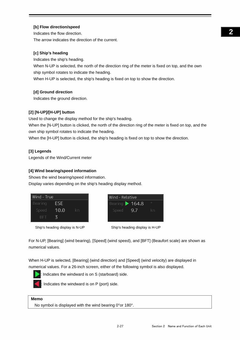
2-27 Section 2 Name and Function of Each Unit
1
2
3
4
5
6
7
8
9
10
11
12
13
14
15
16
17
18
19
20
21
22
23
24
25
APP A
APP B
1
[b] Flow direction/speed
Indicates the flow direction.
The arrow indicates the direction of the current.
[c] Ship’s heading
Indicates the ship's heading.
When N-UP is selected, the north of the direction ring of the meter is fixed on top, and the own
ship symbol rotates to indicate the heading.
When H-UP is selected, the ship's heading is fixed on top to show the direction.
[d] Ground direction
Indicates the ground direction.
[2] [N-UP]/[H-UP] button
Used to change the display method for the ship's heading.
When the [N-UP] button is clicked, the north of the direction ring of the meter is fixed on top, and the
own ship symbol rotates to indicate the heading.
When the [H-UP] button is clicked, the ship's heading is fixed on top to show the direction.
[3] Legends
Legends of the Wind/Current meter
[4] Wind bearing/speed information
Shows the wind bearing/speed information.
Display varies depending on the ship's heading display method.
For N-UP, [Bearing] (wind bearing), [Speed] (wind speed), and [BFT] (Beaufort scale) are shown as
numerical values.
When H-UP is selected, [Bearing] (wind direction) and [Speed] (wind velocity) are displayed in
numerical values. For a 26-inch screen, either of the following symbol is also displayed.
: Indicates the windward is on S (starboard) side.
: Indicates the windward is on P (port) side.
Memo
No symbol is displayed with the wind bearing 0°or 180°.
Ship's heading display is N-UP Ship's heading display is H-UP
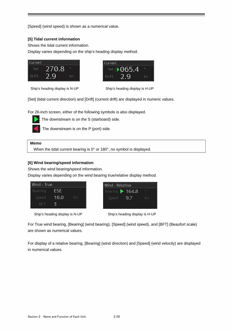
Section 2 Name and Function of Each Unit 2-28
[Speed] (wind speed) is shown as a numerical value.
[5] Tidal current information
Shows the tidal current information.
Display varies depending on the ship’s heading display method.
Ship’s heading display is N-UP Ship’s heading display is H-UP [Set] (tidal current direction) and [Drift] (current drift) are displayed in numeric values.
For 26-inch screen, either of the following symbols is also displayed.
: The downstream is on the S (starboard) side.
: The downstream is on the P (port) side.
Memo
When the tidal current bearing is 0° or 180°, no symbol is displayed.
[6] Wind bearing/speed information
Shows the wind bearing/speed information.
Display varies depending on the wind bearing true/relative display method.
For True wind bearing, [Bearing] (wind bearing), [Speed] (wind speed), and [BFT] (Beaufort scale)
are shown as numerical values.
For display of a relative bearing, [Bearing] (wind direction) and [Speed] (wind velocity) are displayed
in numerical values.
Ship’s heading display is H-UP Ship’s heading display is N-UP

2-29 Section 2 Name and Function of Each Unit
1
2
3
4
5
6
7
8
9
10
11
12
13
14
15
16
17
18
19
20
21
22
23
24
25
APP A
APP B
1
[7] Tidal current information
Shows the tidal current information.
Display varies depending on the ship's heading display method.
Ship’s heading display is N-UP Ship’s heading display is H-UP
[Set] (tidal current direction) and [Drift] (current drift) are displayed in numeric values.
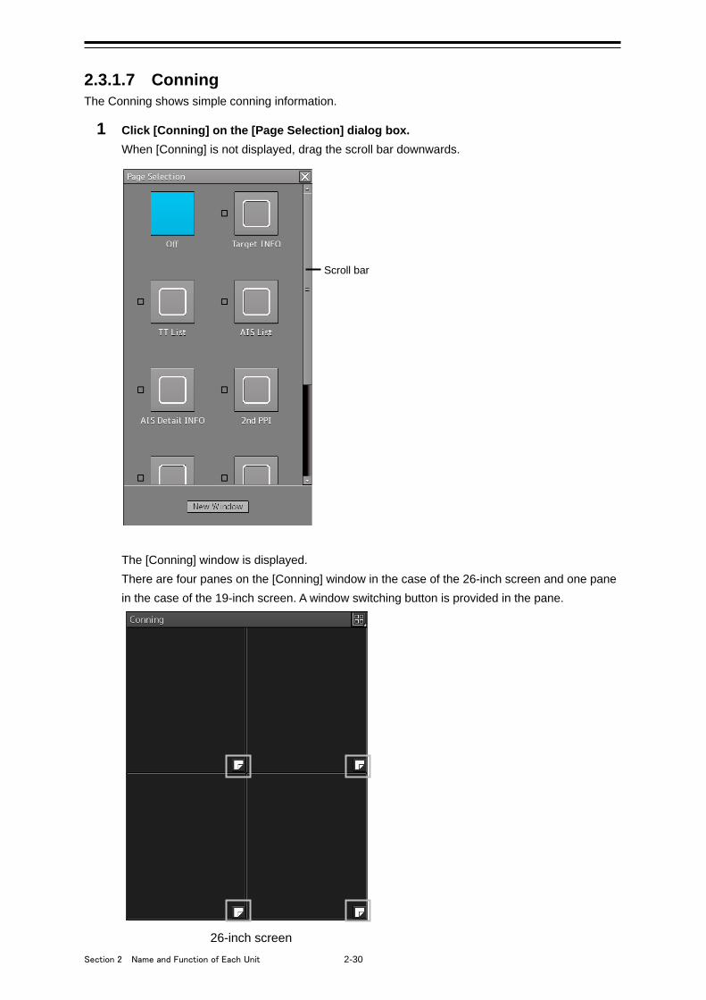
Section 2 Name and Function of Each Unit 2-30
2.3.1.7 Conning The Conning shows simple conning information.
1 Click [Conning] on the [Page Selection] dialog box.
When [Conning] is not displayed, drag the scroll bar downwards.
The [Conning] window is displayed.
There are four panes on the [Conning] window in the case of the 26-inch screen and one pane
in the case of the 19-inch screen. A window switching button is provided in the pane.
26-inch screen
Scroll bar
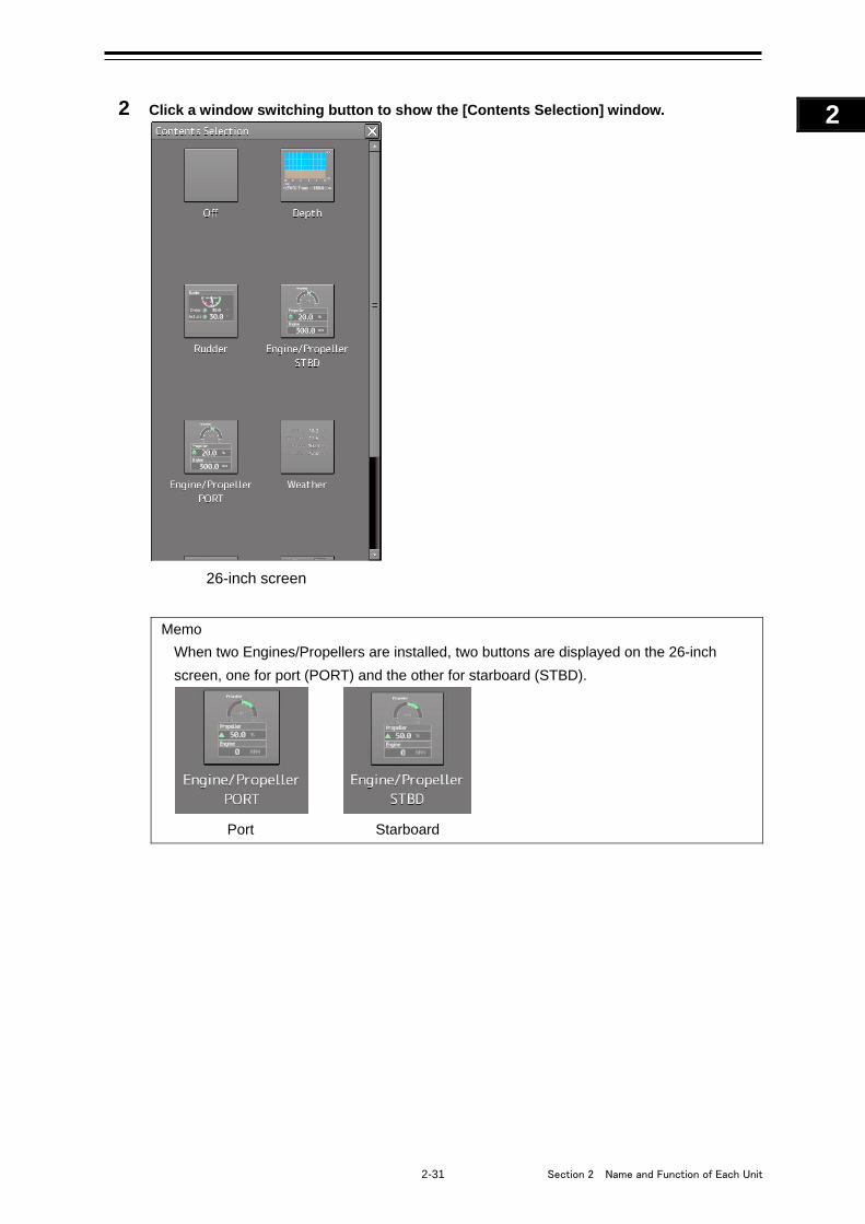
2-31 Section 2 Name and Function of Each Unit
1
2
3
4
5
6
7
8
9
10
11
12
13
14
15
16
17
18
19
20
21
22
23
24
25
APP A
APP B
1
2 Click a window switching button to show the [Contents Selection] window.
26-inch screen
Memo
When two Engines/Propellers are installed, two buttons are displayed on the 26-inch
screen, one for port (PORT) and the other for starboard (STBD).
Port Starboard
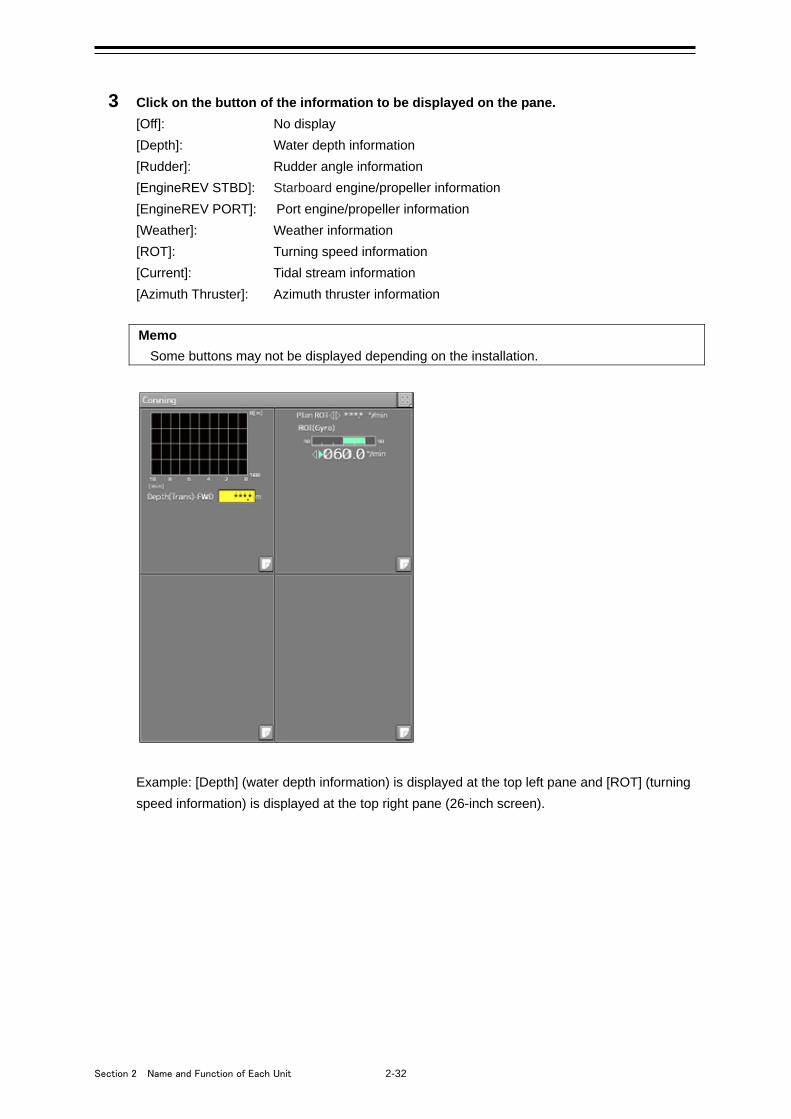
Section 2 Name and Function of Each Unit 2-32
3 Click on the button of the information to be displayed on the pane.
[Off]: No display
[Depth]: Water depth information
[Rudder]: Rudder angle information
[EngineREV STBD]: Starboard engine/propeller information
[EngineREV PORT]: Port engine/propeller information
[Weather]: Weather information
[ROT]: Turning speed information
[Current]: Tidal stream information
[Azimuth Thruster]: Azimuth thruster information
Memo
Some buttons may not be displayed depending on the installation.
Example: [Depth] (water depth information) is displayed at the top left pane and [ROT] (turning
speed information) is displayed at the top right pane (26-inch screen).
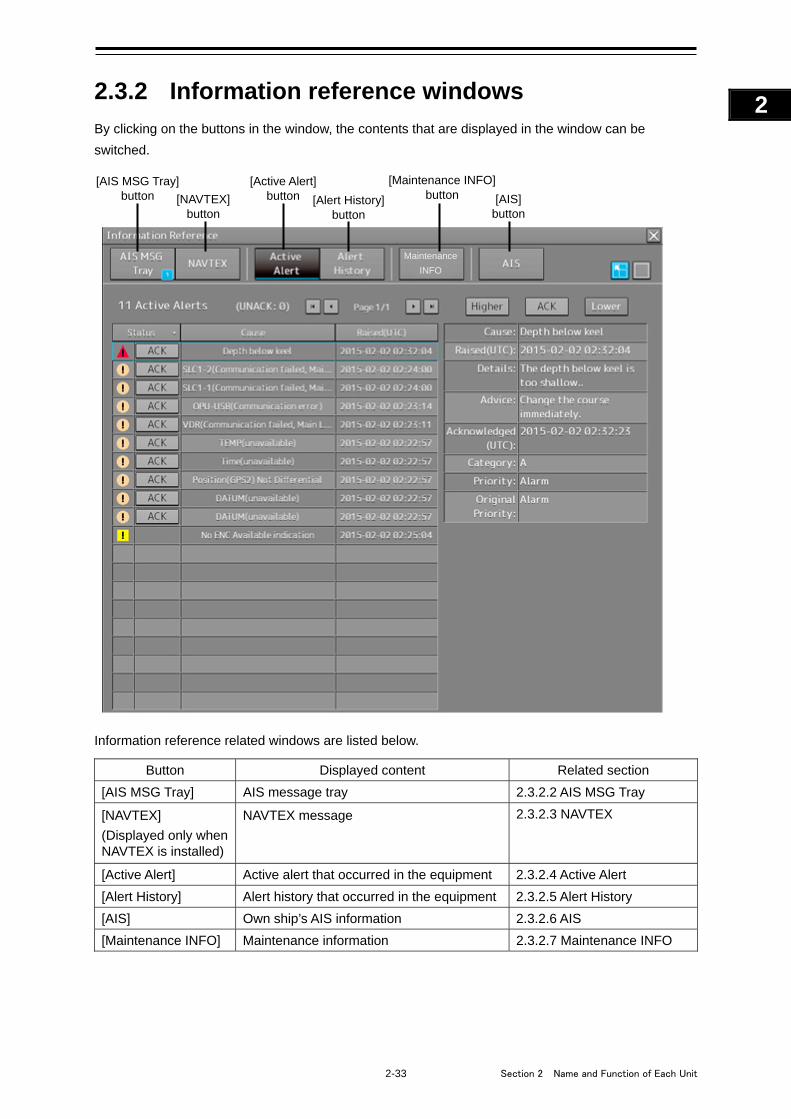
2-33 Section 2 Name and Function of Each Unit
1
2
3
4
5
6
7
8
9
10
11
12
13
14
15
16
17
18
19
20
21
22
23
24
25
APP A
APP B
1
2.3.2 Information reference windows
By clicking on the buttons in the window, the contents that are displayed in the window can be
switched.
Information reference related windows are listed below.
Button Displayed content Related section
[AIS MSG Tray] AIS message tray 2.3.2.2 AIS MSG Tray
[NAVTEX]
(Displayed only when NAVTEX is installed)
NAVTEX message 2.3.2.3 NAVTEX
[Active Alert] Active alert that occurred in the equipment 2.3.2.4 Active Alert
[Alert History] Alert history that occurred in the equipment 2.3.2.5 Alert History
[AIS] Own ship’s AIS information 2.3.2.6 AIS
[Maintenance INFO] Maintenance information 2.3.2.7 Maintenance INFO
[AIS MSG Tray] button
[Active Alert] button [Alert History]
button [AIS]
button [NAVTEX]
button
[Maintenance INFO] button
Maintenance
INFO
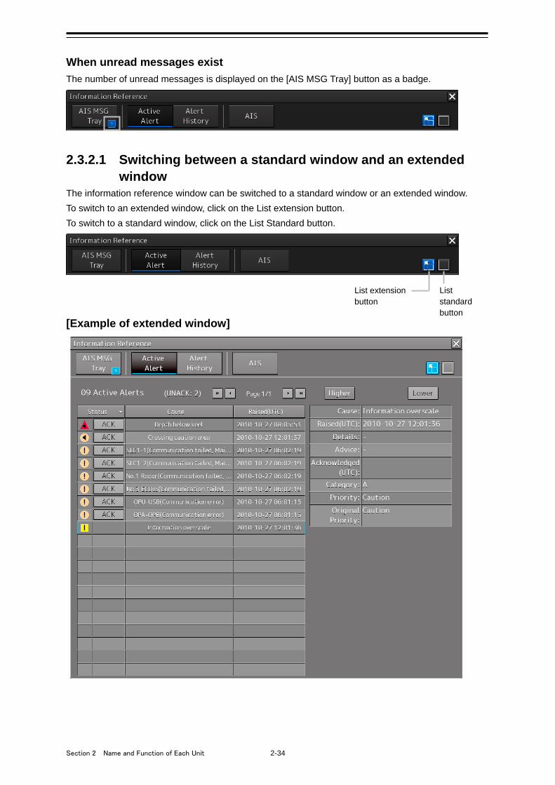
Section 2 Name and Function of Each Unit 2-34
When unread messages exist
The number of unread messages is displayed on the [AIS MSG Tray] button as a badge.
2.3.2.1 Switching between a standard window and an extended window
The information reference window can be switched to a standard window or an extended window.
To switch to an extended window, click on the List extension button.
To switch to a standard window, click on the List Standard button.
[Example of extended window]
List standard button
List extension button
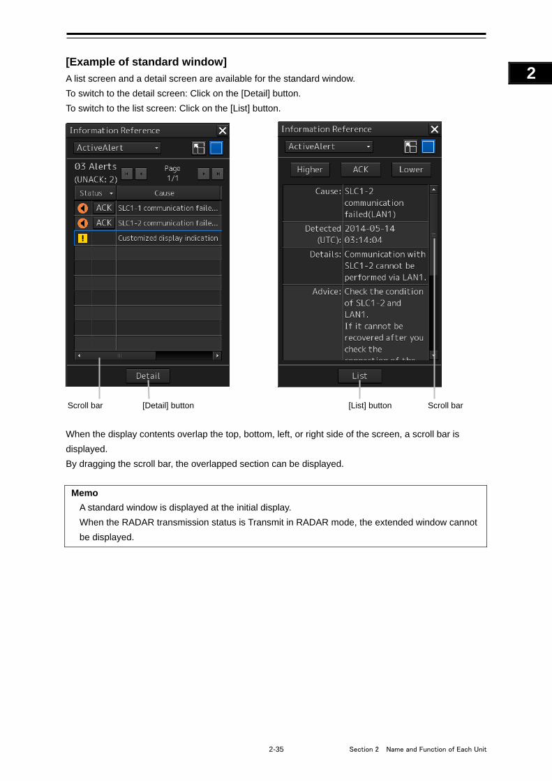
2-35 Section 2 Name and Function of Each Unit
1
2
3
4
5
6
7
8
9
10
11
12
13
14
15
16
17
18
19
20
21
22
23
24
25
APP A
APP B
1
[Example of standard window]
A list screen and a detail screen are available for the standard window.
To switch to the detail screen: Click on the [Detail] button.
To switch to the list screen: Click on the [List] button.
When the display contents overlap the top, bottom, left, or right side of the screen, a scroll bar is
displayed.
By dragging the scroll bar, the overlapped section can be displayed.
Memo
A standard window is displayed at the initial display.
When the RADAR transmission status is Transmit in RADAR mode, the extended window cannot
be displayed.
[Detail] button [List] button Scroll bar Scroll bar
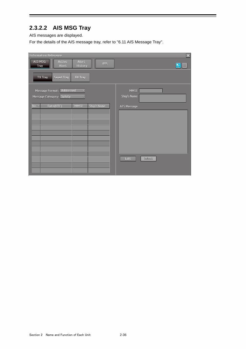
Section 2 Name and Function of Each Unit 2-36
2.3.2.2 AIS MSG Tray AIS messages are displayed.
For the details of the AIS message tray, refer to "6.11 AIS Message Tray".
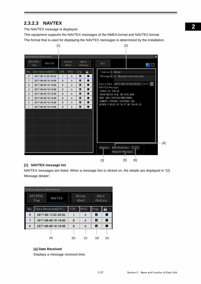
2-37 Section 2 Name and Function of Each Unit
1
2
3
4
5
6
7
8
9
10
11
12
13
14
15
16
17
18
19
20
21
22
23
24
25
APP A
APP B
1
2.3.2.3 NAVTEX The NAVTEX message is displayed.
This equipment supports the NAVTEX messages of the NMEA format and NAVTEX format.
The format that is used for displaying the NAVTEX messages is determined by the installation.
[1] NAVTEX message list
NAVTEX messages are listed. When a message line is clicked on, the details are displayed in “(2)
Message details”.
[a] Date Received
Displays a message received time.
[6] [5] [3]
[4]
[1] [2]
(a) (b) (c) (d) (e)
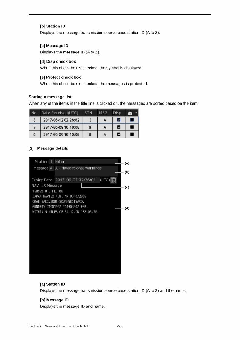
Section 2 Name and Function of Each Unit 2-38
[b] Station ID
Displays the message transmission source base station ID (A to Z).
[c] Message ID
Displays the message ID (A to Z).
[d] Disp check box
When this check box is checked, the symbol is displayed.
[e] Protect check box
When this check box is checked, the messages is protected.
Sorting a message list
When any of the items in the title line is clicked on, the messages are sorted based on the item.
[2] Message details
[a] Station ID
Displays the message transmission source base station ID (A to Z) and the name.
[b] Message ID
Displays the message ID and name.
(a)
(b)
(c)
(d)
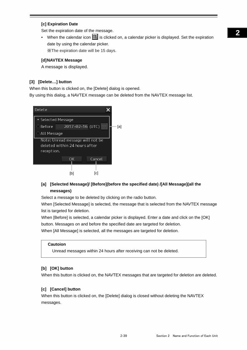
2-39 Section 2 Name and Function of Each Unit
1
2
3
4
5
6
7
8
9
10
11
12
13
14
15
16
17
18
19
20
21
22
23
24
25
APP A
APP B
1
[c] Expiration Date
Set the expiration date of the message.
• When the calendar icon is clicked on, a calendar picker is displayed. Set the expiration
date by using the calendar picker.
※The expiration date will be 15 days.
[d] NAVTEX Message
A message is displayed.
[3] [Delete…] button
When this button is clicked on, the [Delete] dialog is opened.
By using this dialog, a NAVTEX message can be deleted from the NAVTEX message list.
[a] [Selected Message]/ [Before](before the specified date) /[All Message](all the
messages)
Select a message to be deleted by clicking on the radio button.
When [Selected Message] is selected, the message that is selected from the NAVTEX message
list is targeted for deletion.
When [Before] is selected, a calendar picker is displayed. Enter a date and click on the [OK]
button. Messages on and before the specified date are targeted for deletion.
When [All Message] is selected, all the messages are targeted for deletion.
Cautoion
Unread messages within 24 hours after receiving can not be deleted.
[b] [OK] button
When this button is clicked on, the NAVTEX messages that are targeted for deletion are deleted.
[c] [Cancel] button
When this button is clicked on, the [Delete] dialog is closed without deleting the NAVTEX
messages.
[a]
[b] [c]
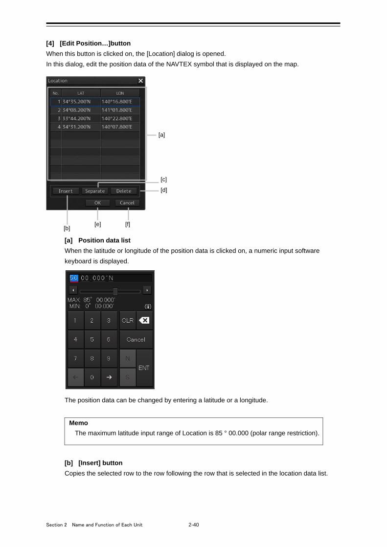
Section 2 Name and Function of Each Unit 2-40
[4] [Edit Position…]button
When this button is clicked on, the [Location] dialog is opened.
In this dialog, edit the position data of the NAVTEX symbol that is displayed on the map.
[a] Position data list
When the latitude or longitude of the position data is clicked on, a numeric input software
keyboard is displayed.
The position data can be changed by entering a latitude or a longitude.
Memo
The maximum latitude input range of Location is 85 ° 00.000 (polar range restriction).
[b] [Insert] button
Copies the selected row to the row following the row that is selected in the location data list.
[a]
[b] [e]
[c]
[d]
[f]
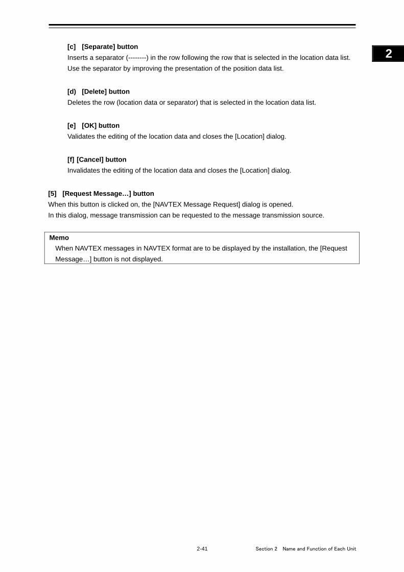
2-41 Section 2 Name and Function of Each Unit
1
2
3
4
5
6
7
8
9
10
11
12
13
14
15
16
17
18
19
20
21
22
23
24
25
APP A
APP B
1
[c] [Separate] button
Inserts a separator (--------) in the row following the row that is selected in the location data list.
Use the separator by improving the presentation of the position data list.
[d) [Delete] button
Deletes the row (location data or separator) that is selected in the location data list.
[e] [OK] button
Validates the editing of the location data and closes the [Location] dialog.
[f] [Cancel] button
Invalidates the editing of the location data and closes the [Location] dialog.
[5] [Request Message…] button
When this button is clicked on, the [NAVTEX Message Request] dialog is opened.
In this dialog, message transmission can be requested to the message transmission source.
Memo
When NAVTEX messages in NAVTEX format are to be displayed by the installation, the [Request
Message…] button is not displayed.
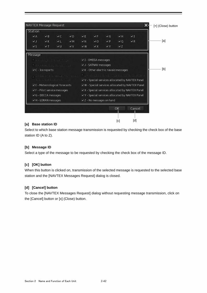
Section 2 Name and Function of Each Unit 2-42
[a] Base station ID
Select to which base station message transmission is requested by checking the check box of the base
station ID (A to Z).
[b] Message ID
Select a type of the message to be requested by checking the check box of the message ID.
[c] [OK] button
When this button is clicked on, transmission of the selected message is requested to the selected base
station and the [NAVTEX Messages Request] dialog is closed.
[d] [Cancel] button
To close the [NAVTEX Messages Request] dialog without requesting message transmission, click on
the [Cancel] button or [x] (Close) button.
[a]
[d] [c]
[b]
[×] (Close) button
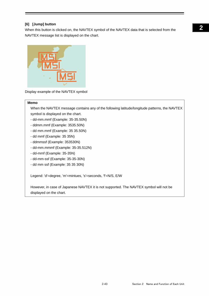
2-43 Section 2 Name and Function of Each Unit
1
2
3
4
5
6
7
8
9
10
11
12
13
14
15
16
17
18
19
20
21
22
23
24
25
APP A
APP B
1
[6] [Jump] button
When this button is clicked on, the NAVTEX symbol of the NAVTEX data that is selected from the
NAVTEX message list is displayed on the chart.
Display example of the NAVTEX symbol
Memo
When the NAVTEX message contains any of the following latitude/longitude patterns, the NAVTEX
symbol is displayed on the chart.
- dd-mm.mmf (Example: 35-35.50N)
- ddmm.mmf (Example: 3535.50N)
- dd mm.mmf (Example: 35 35.50N)
- dd mmf (Example: 35 35N)
- ddmmssf (Example: 353530N)
- dd-mm.mmmf (Example: 35-35.512N)
- dd-mmf (Example: 35-35N)
- dd-mm-ssf (Example: 35-35-30N)
- dd mm ssf (Example: 35 35 30N)
Legend: 'd'=degree, 'm'=mintues, 's'=seconds, 'f'=N/S, E/W
However, in case of Japanese NAVTEX it is not supported. The NAVTEX symbol will not be
displayed on the chart.
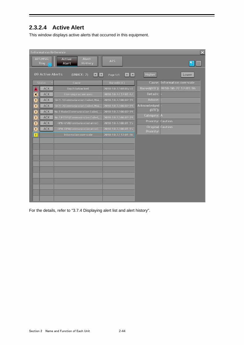
Section 2 Name and Function of Each Unit 2-44
2.3.2.4 Active Alert This window displays active alerts that occurred in this equipment.
For the details, refer to "3.7.4 Displaying alert list and alert history".
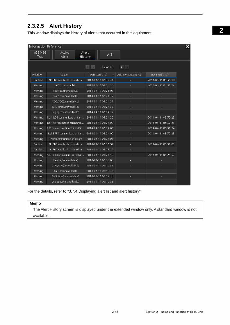
2-45 Section 2 Name and Function of Each Unit
1
2
3
4
5
6
7
8
9
10
11
12
13
14
15
16
17
18
19
20
21
22
23
24
25
APP A
APP B
1
2.3.2.5 Alert History This window displays the history of alerts that occurred in this equipment.
For the details, refer to "3.7.4 Displaying alert list and alert history".
Memo
The Alert History screen is displayed under the extended window only. A standard window is not
available.
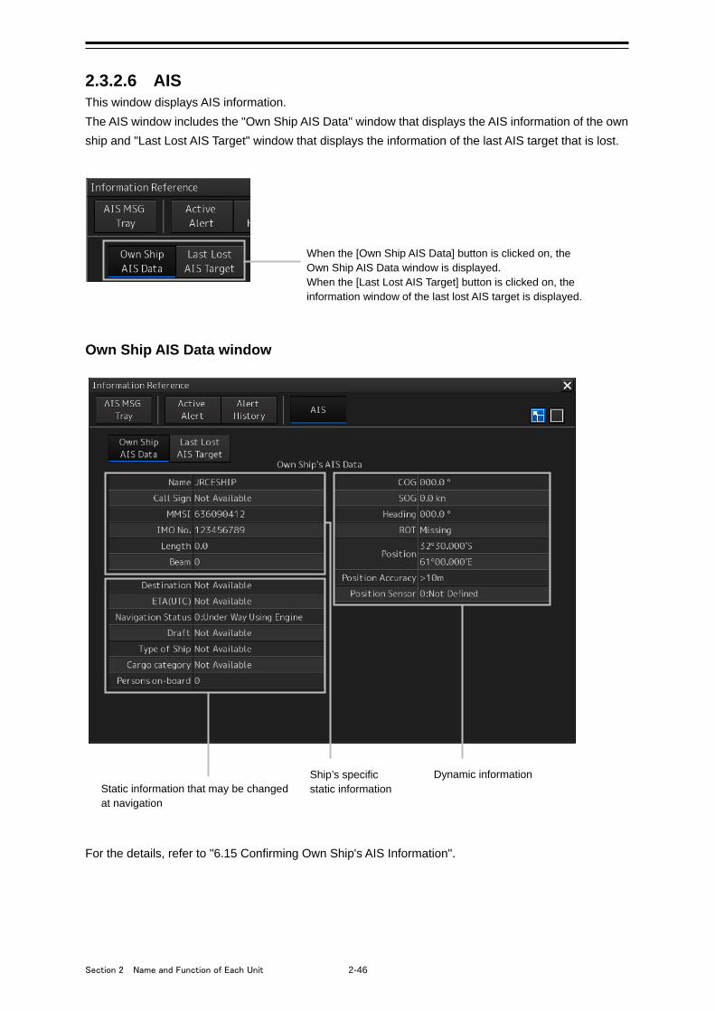
Section 2 Name and Function of Each Unit 2-46
2.3.2.6 AIS This window displays AIS information.
The AIS window includes the "Own Ship AIS Data" window that displays the AIS information of the own
ship and "Last Lost AIS Target" window that displays the information of the last AIS target that is lost.
Own Ship AIS Data window
For the details, refer to "6.15 Confirming Own Ship's AIS Information".
Ship’s specific static information
Dynamic information Static information that may be changed at navigation
When the [Own Ship AIS Data] button is clicked on, the Own Ship AIS Data window is displayed. When the [Last Lost AIS Target] button is clicked on, the information window of the last lost AIS target is displayed.
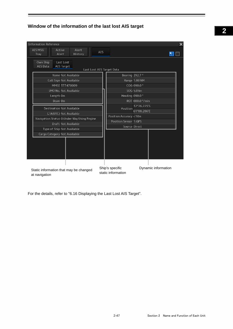
2-47 Section 2 Name and Function of Each Unit
1
2
3
4
5
6
7
8
9
10
11
12
13
14
15
16
17
18
19
20
21
22
23
24
25
APP A
APP B
1
Window of the information of the last lost AIS target
For the details, refer to "6.16 Displaying the Last Lost AIS Target".
Ship’s specific static information
Dynamic information Static information that may be changed at navigation
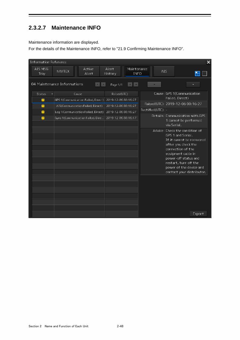
Section 2 Name and Function of Each Unit 2-48
2.3.2.7 Maintenance INFO
Maintenance information are displayed.
For the details of the Maintenance INFO, refer to "21.9 Confirming Maintenance INFO".
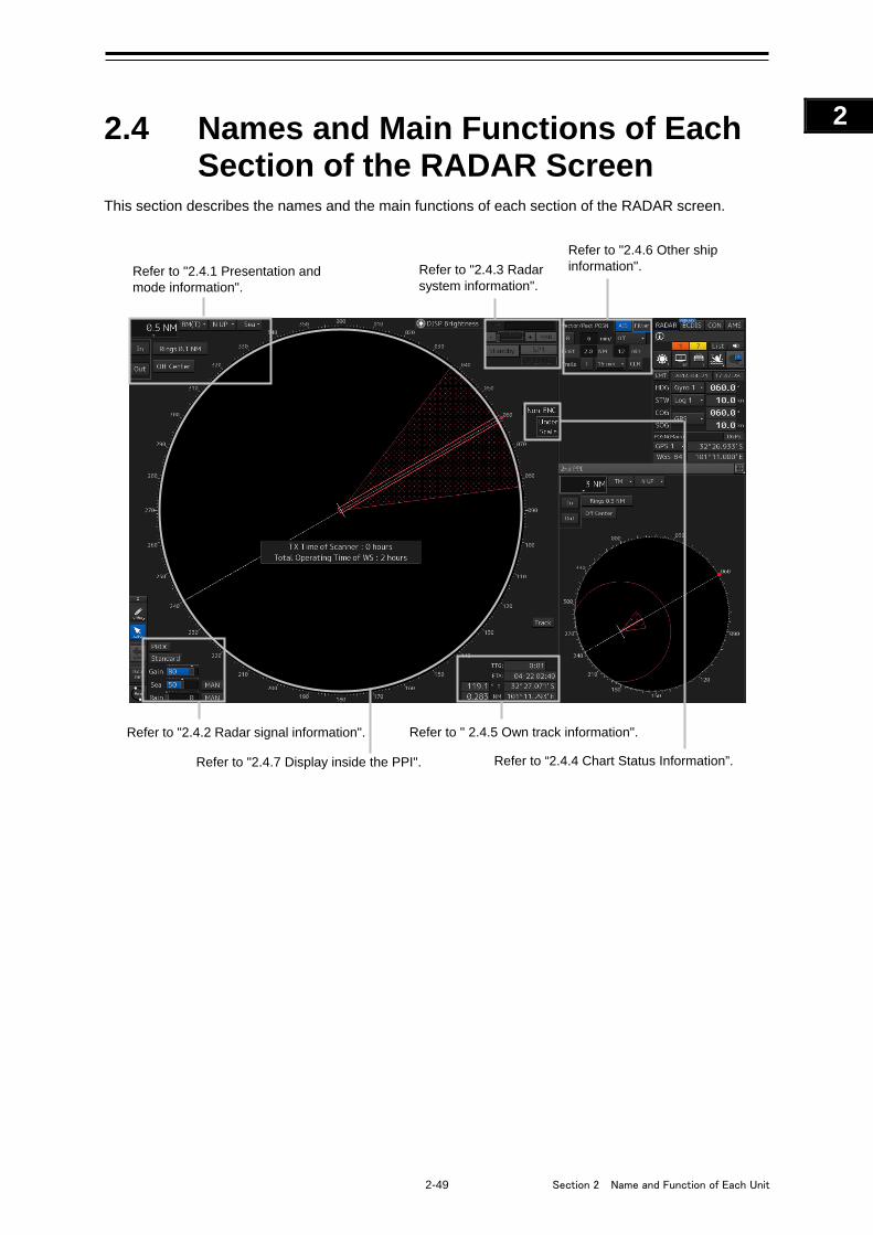
2-49 Section 2 Name and Function of Each Unit
1
2
3
4
5
6
7
8
9
10
11
12
13
14
15
16
17
18
19
20
21
22
23
24
25
APP A
APP B
1
2.4 Names and Main Functions of Each Section of the RADAR Screen
This section describes the names and the main functions of each section of the RADAR screen.
Refer to "2.4.6 Other ship information". Refer to "2.4.3 Radar
system information". Refer to "2.4.1 Presentation and mode information".
Refer to " 2.4.5 Own track information".
Refer to "2.4.7 Display inside the PPI".
Refer to "2.4.2 Radar signal information".
Refer to “2.4.4 Chart Status Information”.
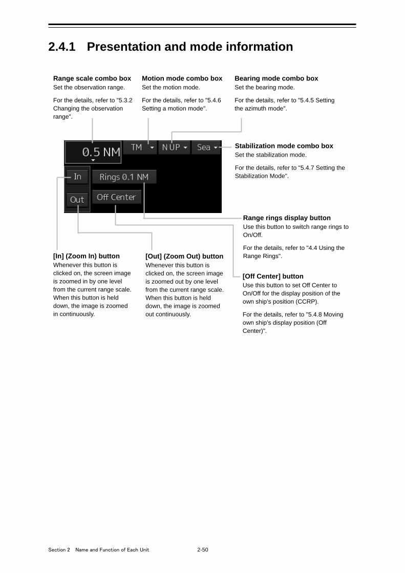
Section 2 Name and Function of Each Unit 2-50
2.4.1 Presentation and mode information
Range scale combo box Set the observation range. For the details, refer to "5.3.2 Changing the observation range".
Motion mode combo box Set the motion mode. For the details, refer to "5.4.6 Setting a motion mode".
Bearing mode combo box Set the bearing mode. For the details, refer to "5.4.5 Setting the azimuth mode".
Stabilization mode combo box Set the stabilization mode. For the details, refer to "5.4.7 Setting the Stabilization Mode".
[Out] (Zoom Out) button Whenever this button is clicked on, the screen image is zoomed out by one level from the current range scale. When this button is held down, the image is zoomed out continuously.
[In] (Zoom In) button Whenever this button is clicked on, the screen image is zoomed in by one level from the current range scale. When this button is held down, the image is zoomed in continuously.
Range rings display button Use this button to switch range rings to On/Off. For the details, refer to "4.4 Using the Range Rings".
[Off Center] button Use this button to set Off Center to On/Off for the display position of the own ship’s position (CCRP). For the details, refer to "5.4.8 Moving own ship’s display position (Off Center)".
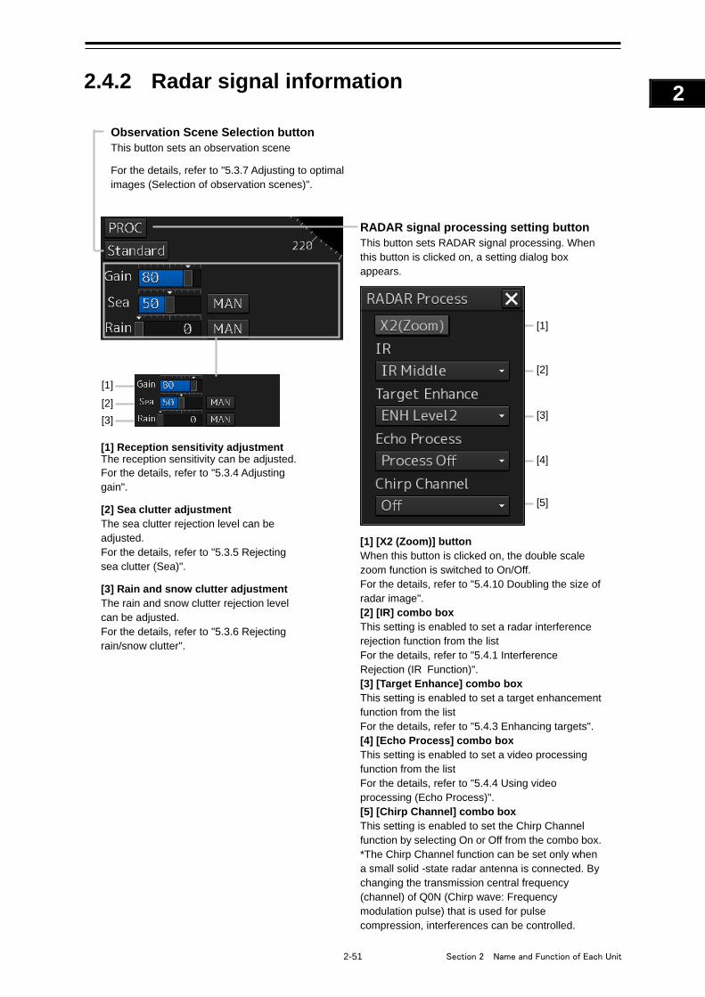
2-51 Section 2 Name and Function of Each Unit
1
2
3
4
5
6
7
8
9
10
11
12
13
14
15
16
17
18
19
20
21
22
23
24
25
APP A
APP B
1
2.4.2 Radar signal information
RADAR signal processing setting button This button sets RADAR signal processing. When this button is clicked on, a setting dialog box appears.
[1] [X2 (Zoom)] button When this button is clicked on, the double scale zoom function is switched to On/Off. For the details, refer to "5.4.10 Doubling the size of radar image". [2] [IR] combo box This setting is enabled to set a radar interference rejection function from the list For the details, refer to "5.4.1 Interference Rejection (IR Function)". [3] [Target Enhance] combo box This setting is enabled to set a target enhancement function from the list For the details, refer to "5.4.3 Enhancing targets". [4] [Echo Process] combo box This setting is enabled to set a video processing function from the list For the details, refer to "5.4.4 Using video processing (Echo Process)". [5] [Chirp Channel] combo box This setting is enabled to set the Chirp Channel function by selecting On or Off from the combo box. *The Chirp Channel function can be set only when a small solid -state radar antenna is connected. By changing the transmission central frequency (channel) of Q0N (Chirp wave: Frequency modulation pulse) that is used for pulse compression, interferences can be controlled.
[1] Reception sensitivity adjustment The reception sensitivity can be adjusted. For the details, refer to "5.3.4 Adjusting gain". [2] Sea clutter adjustment The sea clutter rejection level can be adjusted. For the details, refer to "5.3.5 Rejecting sea clutter (Sea)". [3] Rain and snow clutter adjustment The rain and snow clutter rejection level can be adjusted. For the details, refer to "5.3.6 Rejecting rain/snow clutter".
Observation Scene Selection button This button sets an observation scene For the details, refer to "5.3.7 Adjusting to optimal images (Selection of observation scenes)".
[1] [2] [3]
[1]
[2]
[3]
[4]
[5]
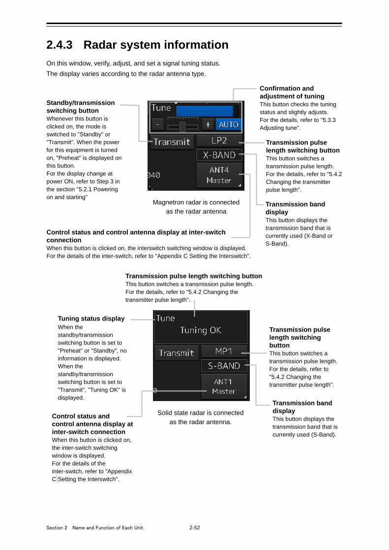
Section 2 Name and Function of Each Unit 2-52
2.4.3 Radar system information
On this window, verify, adjust, and set a signal tuning status.
The display varies according to the radar antenna type.
Confirmation and adjustment of tuning This button checks the tuning status and slightly adjusts. For the details, refer to "5.3.3 Adjusting tune".
Standby/transmission switching button Whenever this button is clicked on, the mode is switched to "Standby" or "Transmit". When the power for this equipment is turned on, "Preheat" is displayed on this button. For the display change at power ON, refer to Step 3 in the section "5.2.1 Powering on and starting"
Transmission pulse length switching button This button switches a transmission pulse length. For the details, refer to "5.4.2 Changing the transmitter pulse length".
Transmission band display This button displays the transmission band that is currently used (X-Band or S-Band).
Control status and control antenna display at inter-switch connection When this button is clicked on, the interswitch switching window is displayed. For the details of the inter-switch, refer to "Appendix C Setting the Interswitch".
Magnetron radar is connected as the radar antenna
Tuning status display When the standby/transmission switching button is set to "Preheat" or "Standby", no information is displayed. When the standby/transmission switching button is set to "Transmit", "Tuning OK" is displayed.
Transmission pulse length switching button This button switches a transmission pulse length. For the details, refer to "5.4.2 Changing the transmitter pulse length".
Transmission pulse length switching button This button switches a transmission pulse length. For the details, refer to "5.4.2 Changing the transmitter pulse length".
Transmission band display This button displays the transmission band that is currently used (S-Band).
Control status and control antenna display at inter-switch connection When this button is clicked on, the inter-switch switching window is displayed. For the details of the inter-switch, refer to "Appendix C Setting the Interswitch".
Solid state radar is connected as the radar antenna.

2-53 Section 2 Name and Function of Each Unit
1
2
3
4
5
6
7
8
9
10
11
12
13
14
15
16
17
18
19
20
21
22
23
24
25
APP A
APP B
1
Note
When the RADAR transmission status in RADAR mode is Transmit, the following menu items cannot
be selected.
• [Chart]
• [Chart Maintenance]
• [Help]
2.4.4 Chart Status Information
Memo
Official/Unofficial information of the chart
“ENC” is displayed when the ENC chart contains C-MAP ENC.
”Non-ENC” is displayed for a chart other than an ENC chart.
Underscale/Overscale of the chart
”Under Scale” is displayed when the display scale is reduced to a half or smaller size of the
original size of the chart.
“Over Scale” is displayed when the display scale is expanded to a double or larger size of the
original size of the chart.
Official/Unofficial information of the chart When an ENC chart is displayed, “ENC” is displayed. When a chart other than ENC is displayed, “Non-ENC” is displayed.
Underscale/Overscale of the chart When the chart is displayed with underscale, “Under Scale” is displayed. When the chart is displayed with overscale, “Over Scale” is displayed.
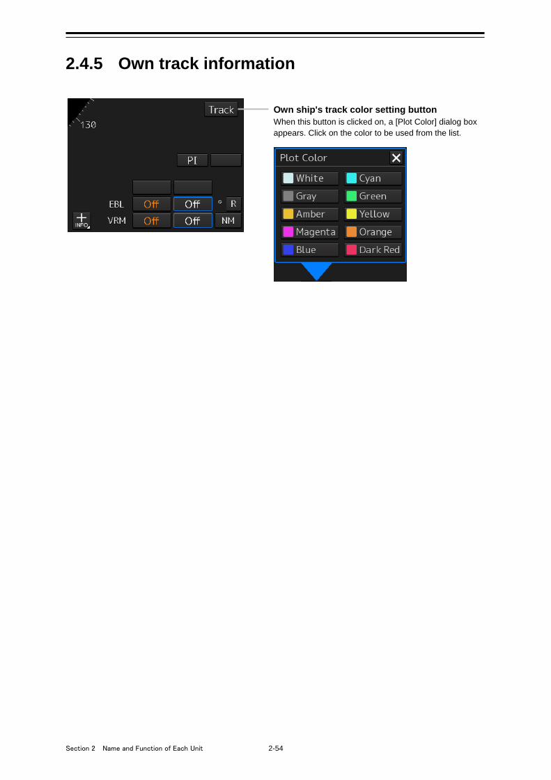
Section 2 Name and Function of Each Unit 2-54
2.4.5 Own track information
Own ship's track color setting button When this button is clicked on, a [Plot Color] dialog box appears. Click on the color to be used from the list.
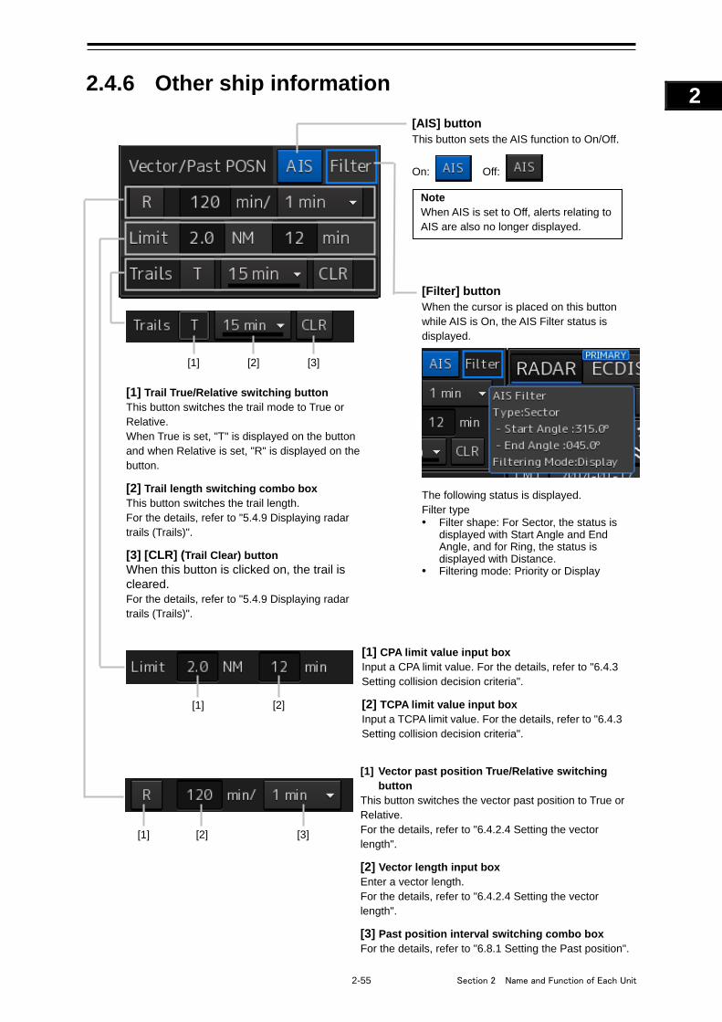
2-55 Section 2 Name and Function of Each Unit
1
2
3
4
5
6
7
8
9
10
11
12
13
14
15
16
17
18
19
20
21
22
23
24
25
APP A
APP B
1
2.4.6 Other ship information
[Filter] button When the cursor is placed on this button while AIS is On, the AIS Filter status is displayed. The following status is displayed. Filter type • Filter shape: For Sector, the status is
displayed with Start Angle and End Angle, and for Ring, the status is displayed with Distance.
• Filtering mode: Priority or Display
[AIS] button This button sets the AIS function to On/Off.
On: Off:
Note When AIS is set to Off, alerts relating to AIS are also no longer displayed.
[1] Trail True/Relative switching button This button switches the trail mode to True or Relative. When True is set, "T" is displayed on the button and when Relative is set, "R" is displayed on the button. [2] Trail length switching combo box This button switches the trail length. For the details, refer to "5.4.9 Displaying radar trails (Trails)". [3] [CLR] (Trail Clear) button When this button is clicked on, the trail is cleared. For the details, refer to "5.4.9 Displaying radar trails (Trails)".
[1] [2]
[1] [2] [3]
[1] Vector past position True/Relative switching button
This button switches the vector past position to True or Relative. For the details, refer to "6.4.2.4 Setting the vector length". [2] Vector length input box Enter a vector length. For the details, refer to "6.4.2.4 Setting the vector length". [3] Past position interval switching combo box For the details, refer to "6.8.1 Setting the Past position".
[1] CPA limit value input box Input a CPA limit value. For the details, refer to "6.4.3 Setting collision decision criteria". [2] TCPA limit value input box Input a TCPA limit value. For the details, refer to "6.4.3 Setting collision decision criteria".
[2] [3] [1]
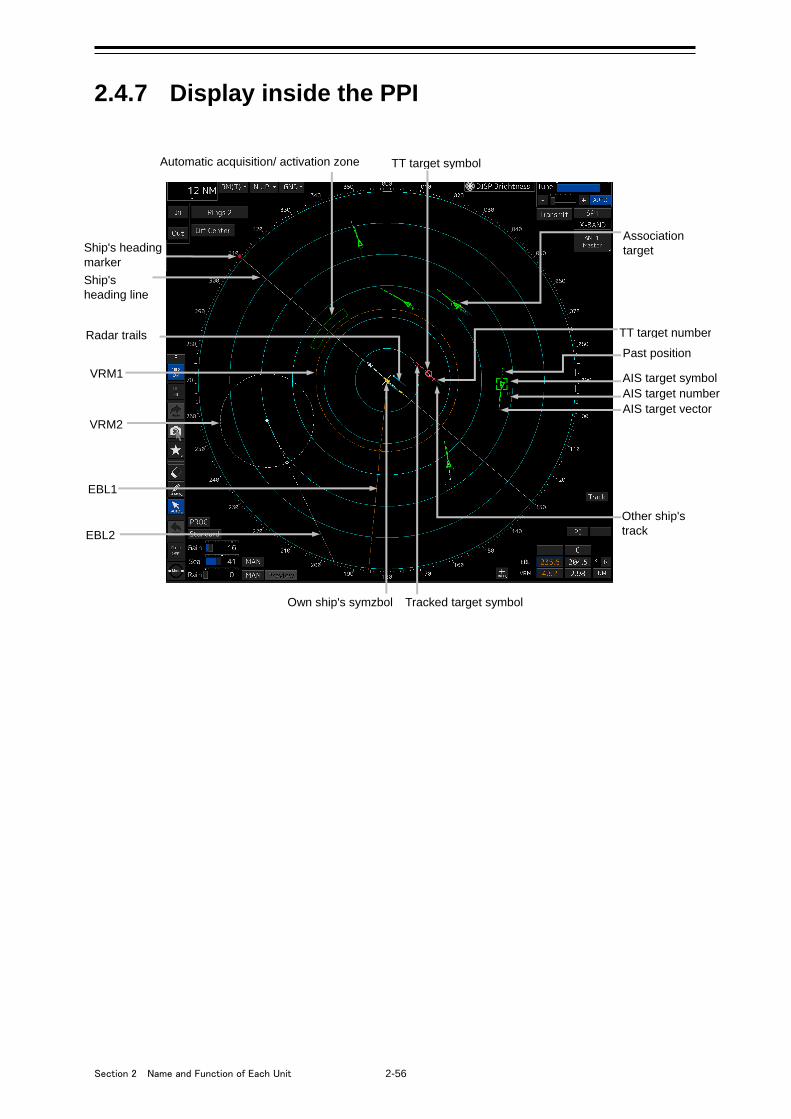
Section 2 Name and Function of Each Unit 2-56
2.4.7 Display inside the PPI
VRM1
VRM2
EBL1
EBL2
Ship's heading marker
TT target symbol
Radar trails
Automatic acquisition/ activation zone
Association target
AIS target number
Past position
Other ship's track
AIS target symbol
Ship's heading line
TT target number
AIS target vector
Own ship's symzbol Tracked target symbol

2-57 Section 2 Name and Function of Each Unit
1
2
3
4
5
6
7
8
9
10
11
12
13
14
15
16
17
18
19
20
21
22
23
24
25
APP A
APP B
1
2.5 Names and Main Functions of Each Section of the ECDIS Screen (Option)
The screen operation units specific to ECDIS are "Chart Information Area" and "Sub Information Area".
For "Chart Information Area", the contents vary depending on whether the chart is ENC/C-MAP or
RNC.
For "Sub Information Area", the contents are common regardless of the chart type.
Refer to "2.5.1 Chart Information Area (ENC/C-MAP)". Refer to "2.5.3 Sub Information Area".
ENC/C-MAP Refer to "2.5.2 Chart Information Area (RNC)". Refer to "2.5.3 Sub Information Area".
RNC
Refer to "2.5.4 Bottom Bar (Sub Information Area)".
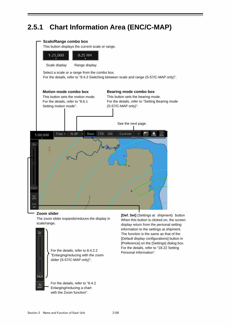
Section 2 Name and Function of Each Unit 2-58
2.5.1 Chart Information Area (ENC/C-MAP)
Scale/Range combo box This button displays the current scale or range.
Scale display Range display Select a scale or a range from the combo box. For the details, refer to "8.4.3 Switching between scale and range (S-57/C-MAP only)".
Motion mode combo box This button sets the motion mode. For the details, refer to "8.6.1 Setting motion mode".
Bearing mode combo box This button sets the bearing mode. For the details, refer to "Setting Bearing mode (S-57/C-MAP only)".
Zoom slider The zoom slider expands/reduces the display in scale/range.
For the details, refer to 8.4.2.2 "Enlarging/reducing with the zoom slider (S-57/C-MAP only)".
For the details, refer to "8.4.2 Enlarging/reducing a chart with the Zoom function".
See the next page.
[Def. Set] (Settings at shipment) button When this button is clicked on, the screen display return from the personal setting information to the settings at shipment. The function is the same as that of the [Default display configurations] button in [Preference] on the [Settings] dialog box. For the details, refer to "18.22 Setting Personal Information".
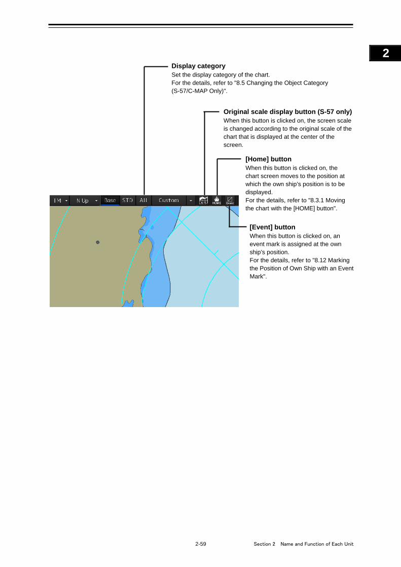
2-59 Section 2 Name and Function of Each Unit
1
2
3
4
5
6
7
8
9
10
11
12
13
14
15
16
17
18
19
20
21
22
23
24
25
APP A
APP B
1
Original scale display button (S-57 only) When this button is clicked on, the screen scale is changed according to the original scale of the chart that is displayed at the center of the screen.
[Home] button When this button is clicked on, the chart screen moves to the position at which the own ship’s position is to be displayed. For the details, refer to "8.3.1 Moving the chart with the [HOME] button".
[Event] button When this button is clicked on, an event mark is assigned at the own ship’s position. For the details, refer to "8.12 Marking the Position of Own Ship with an Event Mark".
Display category Set the display category of the chart. For the details, refer to "8.5 Changing the Object Category (S-57/C-MAP Only)".
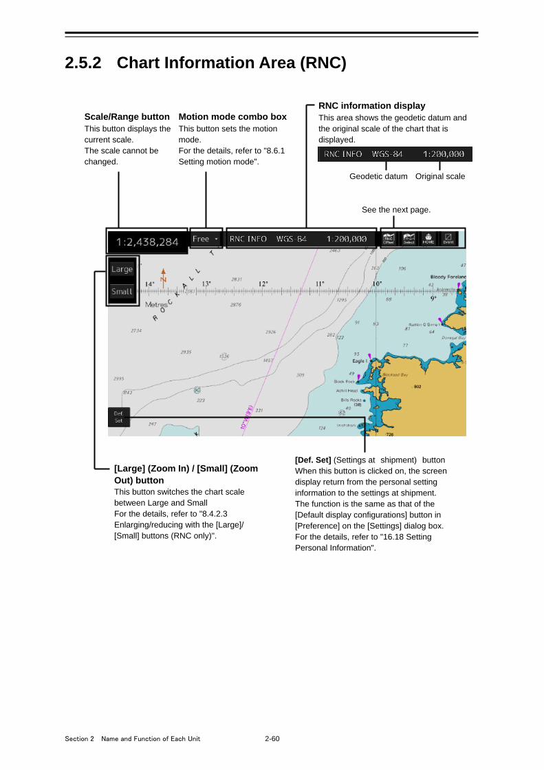
Section 2 Name and Function of Each Unit 2-60
2.5.2 Chart Information Area (RNC)
Scale/Range button This button displays the current scale. The scale cannot be changed.
Motion mode combo box This button sets the motion mode. For the details, refer to "8.6.1 Setting motion mode".
[Large] (Zoom In) / [Small] (Zoom Out) button This button switches the chart scale between Large and Small For the details, refer to "8.4.2.3 Enlarging/reducing with the [Large]/ [Small] buttons (RNC only)".
See the next page.
RNC information display This area shows the geodetic datum and the original scale of the chart that is displayed.
Original scale Geodetic datum
[Def. Set] (Settings at shipment) button When this button is clicked on, the screen display return from the personal setting information to the settings at shipment. The function is the same as that of the [Default display configurations] button in [Preference] on the [Settings] dialog box. For the details, refer to "16.18 Setting Personal Information".
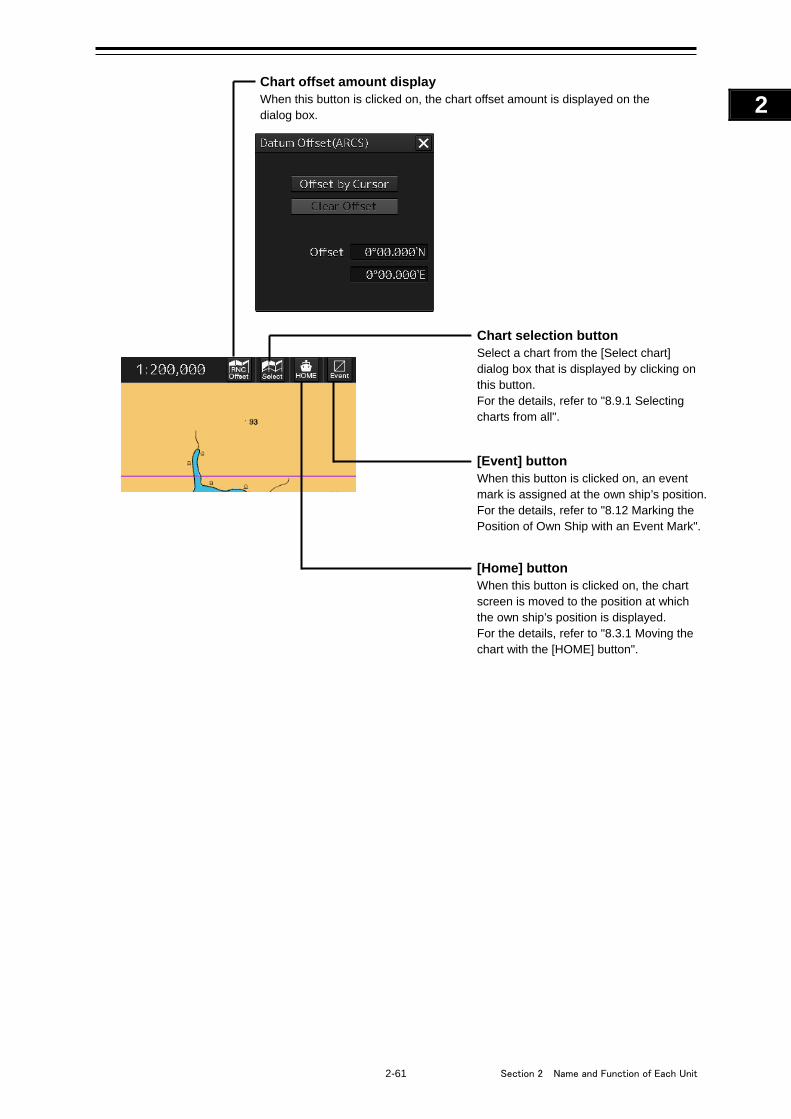
2-61 Section 2 Name and Function of Each Unit
1
2
3
4
5
6
7
8
9
10
11
12
13
14
15
16
17
18
19
20
21
22
23
24
25
APP A
APP B
1
Chart offset amount display When this button is clicked on, the chart offset amount is displayed on the dialog box.
Chart selection button Select a chart from the [Select chart] dialog box that is displayed by clicking on this button. For the details, refer to "8.9.1 Selecting charts from all".
[Home] button When this button is clicked on, the chart screen is moved to the position at which the own ship’s position is displayed. For the details, refer to "8.3.1 Moving the chart with the [HOME] button".
[Event] button When this button is clicked on, an event mark is assigned at the own ship’s position. For the details, refer to "8.12 Marking the Position of Own Ship with an Event Mark".
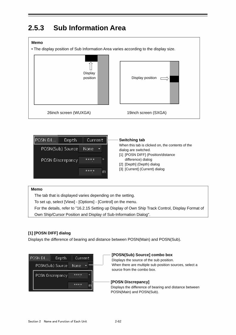
Section 2 Name and Function of Each Unit 2-62
2.5.3 Sub Information Area
Memo
The tab that is displayed varies depending on the setting.
To set up, select [View] - [Options] - [Control] on the menu.
For the details, refer to "16.2.15 Setting up Display of Own Ship Track Control, Display Format of
Own Ship/Cursor Position and Display of Sub-Information Dialog".
[1] [POSN DIFF] dialog
Displays the difference of bearing and distance between POSN(Main) and POSN(Sub).
[POSN(Sub) Source] combo box Displays the source of the sub position. When there are multiple sub position sources, select a source from the combo box.
[POSN Discrepancy] Displays the difference of bearing and distance between POSN(Main) and POSN(Sub).
Switching tab When this tab is clicked on, the contents of the dialog are switched. [1] [POSN DIFF] (Position/distance
difference) dialog [2] [Depth] (Depth) dialog [3] [Current] (Current) dialog
Memo
• The display position of Sub Information Area varies according to the display size.
26inch screen (WUXGA) 19inch screen (SXGA)
Display position
Display position
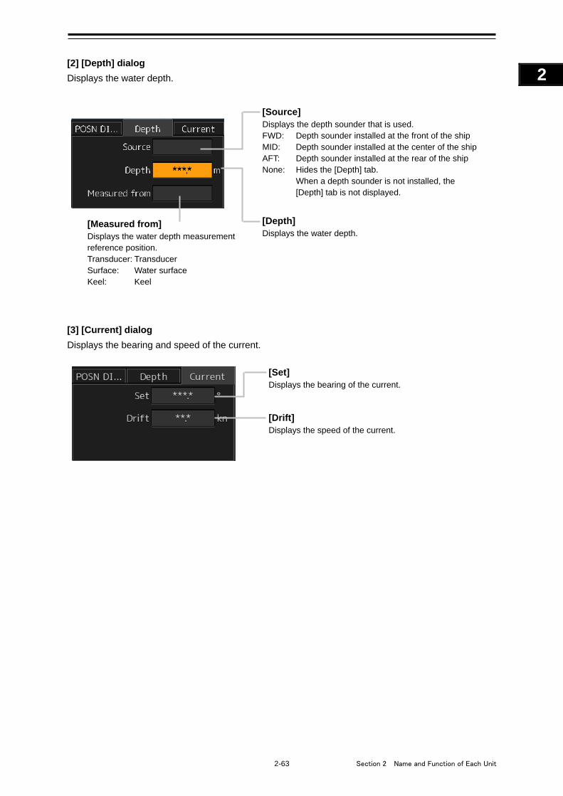
2-63 Section 2 Name and Function of Each Unit
1
2
3
4
5
6
7
8
9
10
11
12
13
14
15
16
17
18
19
20
21
22
23
24
25
APP A
APP B
1
[2] [Depth] dialog
Displays the water depth.
[3] [Current] dialog
Displays the bearing and speed of the current.
[Set] Displays the bearing of the current.
[Drift] Displays the speed of the current.
[Source] Displays the depth sounder that is used. FWD: Depth sounder installed at the front of the ship MID: Depth sounder installed at the center of the ship AFT: Depth sounder installed at the rear of the ship None: Hides the [Depth] tab.
When a depth sounder is not installed, the [Depth] tab is not displayed.
[Measured from] Displays the water depth measurement reference position. Transducer: Transducer Surface: Water surface Keel: Keel
[Depth] Displays the water depth.
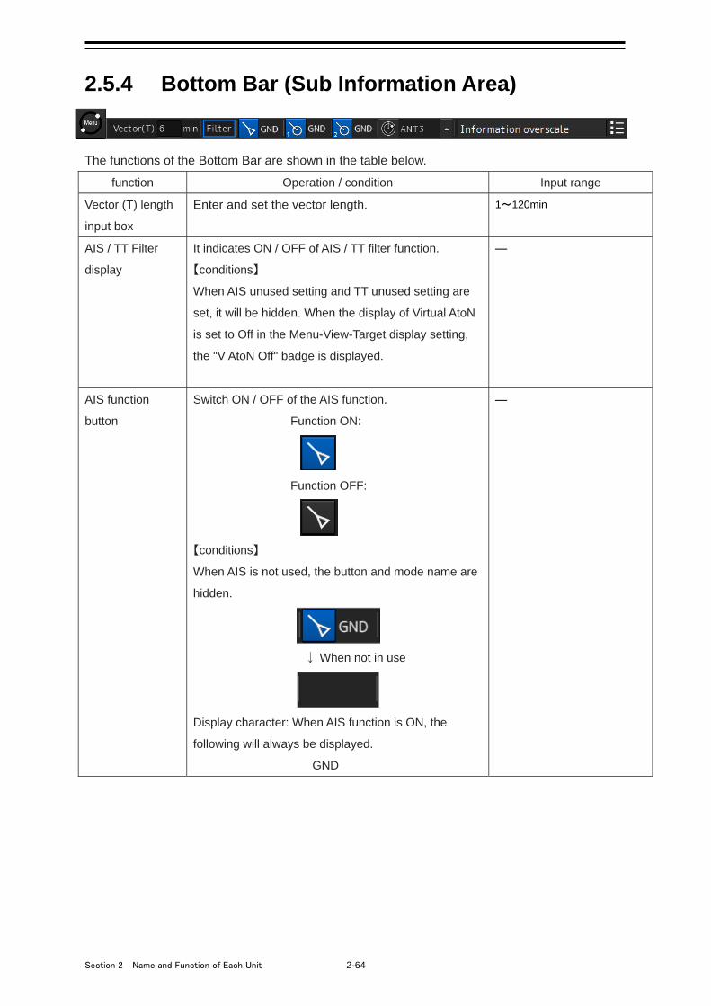
Section 2 Name and Function of Each Unit 2-64
2.5.4 Bottom Bar (Sub Information Area)
The functions of the Bottom Bar are shown in the table below.
function Operation / condition Input range
Vector (T) length
input box
Enter and set the vector length. 1~120min
AIS / TT Filter
display
It indicates ON / OFF of AIS / TT filter function.
【conditions】
When AIS unused setting and TT unused setting are
set, it will be hidden. When the display of Virtual AtoN
is set to Off in the Menu-View-Target display setting,
the "V AtoN Off" badge is displayed.
―
AIS function
button
Switch ON / OFF of the AIS function.
Function ON:
Function OFF:
【conditions】
When AIS is not used, the button and mode name are
hidden.
↓ When not in use
Display character: When AIS function is ON, the
following will always be displayed.
GND
―
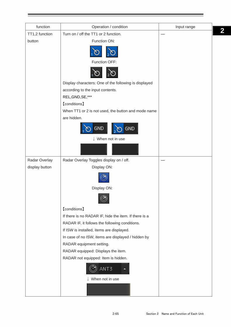
2-65 Section 2 Name and Function of Each Unit
1
2
3
4
5
6
7
8
9
10
11
12
13
14
15
16
17
18
19
20
21
22
23
24
25
APP A
APP B
1
function Operation / condition Input range
TT1,2 function
button
Turn on / off the TT1 or 2 function.
Function ON:
Function OFF:
Display characters: One of the following is displayed
according to the input contents.
REL,GND,SE,***
【conditions】
When TT1 or 2 is not used, the button and mode name
are hidden.
↓ When not in use
―
Radar Overlay
display button
Radar Overlay Toggles display on / off.
Display ON:
Display ON:
【conditions】
If there is no RADAR IF, hide the item. If there is a
RADAR IF, it follows the following conditions.
If ISW is installed, items are displayed.
In case of no ISW, items are displayed / hidden by
RADAR equipment setting.
RADAR equipped: Displays the item.
RADAR not equipped: Item is hidden.
↓ When not in use
―
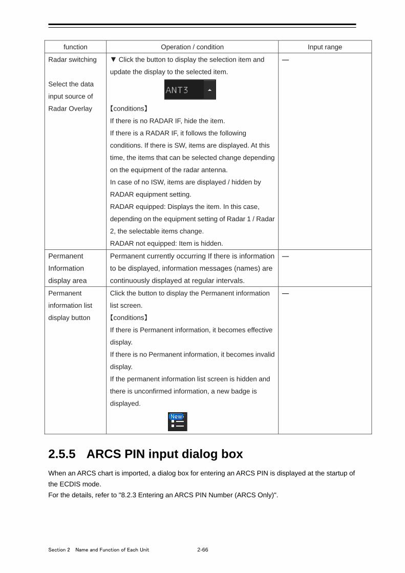
Section 2 Name and Function of Each Unit 2-66
function Operation / condition Input range
Radar switching
Select the data
input source of
Radar Overlay
▼ Click the button to display the selection item and
update the display to the selected item.
【conditions】
If there is no RADAR IF, hide the item.
If there is a RADAR IF, it follows the following
conditions. If there is SW, items are displayed. At this
time, the items that can be selected change depending
on the equipment of the radar antenna.
In case of no ISW, items are displayed / hidden by
RADAR equipment setting.
RADAR equipped: Displays the item. In this case,
depending on the equipment setting of Radar 1 / Radar
2, the selectable items change.
RADAR not equipped: Item is hidden.
―
Permanent
Information
display area
Permanent currently occurring If there is information
to be displayed, information messages (names) are
continuously displayed at regular intervals.
―
Permanent
information list
display button
Click the button to display the Permanent information
list screen.
【conditions】
If there is Permanent information, it becomes effective
display.
If there is no Permanent information, it becomes invalid
display.
If the permanent information list screen is hidden and
there is unconfirmed information, a new badge is
displayed.
―
2.5.5 ARCS PIN input dialog box
When an ARCS chart is imported, a dialog box for entering an ARCS PIN is displayed at the startup of
the ECDIS mode.
For the details, refer to "8.2.3 Entering an ARCS PIN Number (ARCS Only)".
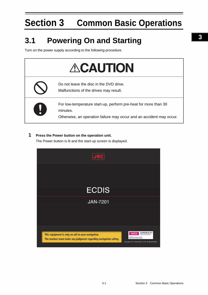
3-1 Section 3 Common Basic Operations
1
2
3
4
5
6
7
8
9
10
11
12
13
14
15
16
17
18
19
20
21
22
23
24
25
APP A
APP B
1
Section 3 Common Basic Operations
3.1 Powering On and Starting Turn on the power supply according to the following procedure.
Do not leave the disc in the DVD drive.
Malfunctions of the drives may result.
For low-temperature start-up, perform pre-heat for more than 30
minutes.
Otherwise, an operation failure may occur and an accident may occur.
1 Press the Power button on the operation unit.
The Power button is lit and the start-up screen is displayed.

Section 3 Common Basic Operations 3-2
Memo
• At the center of the start-up screen, "RADAR" (in the case of RADAR), "ECDIS" (in the
case of ECDIS), or "CHART RADAR" (in the case of CHART RADAR) is displayed
depending on the type of the equipment.
• When the power is supplied while all the power supplies are disconnected, the indicator
can be started automatically without pressing the Power button.
After the start-up screen is displayed, the task menu is displayed after a brief interval.
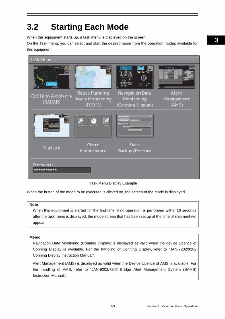
3-3 Section 3 Common Basic Operations
1
2
3
4
5
6
7
8
9
10
11
12
13
14
15
16
17
18
19
20
21
22
23
24
25
APP A
APP B
1
3.2 Starting Each Mode When this equipment starts up, a task menu is displayed on the screen.
On the Task menu, you can select and start the desired mode from the operation modes available for
this equipment.
When the button of the mode to be executed is clicked on, the screen of the mode is displayed.
Note
When this equipment is started for the first time, if no operation is performed within 10 seconds
after the task menu is displayed, the mode screen that has been set up at the time of shipment will
appear.
Memo
Navigation Data Monitoring (Conning Display) is displayed as valid when the device Licence of
Conning Display is available. For the handling of Conning Display, refer to “JAN-7202/9202
Conning Display Instruction Manual”.
Alert Management (AMS) is displayed as valid when the Device Licence of AMS is available. For
the handling of AMS, refer to “JAN-9202/7202 Bridge Alert Management System (BAMS)
Instruction Manual”.
Task Menu Display Example
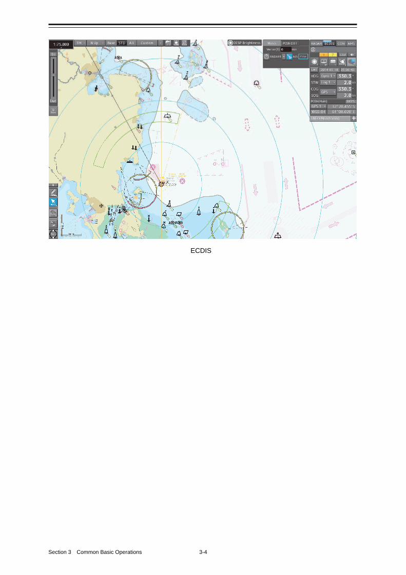
Section 3 Common Basic Operations 3-4
ECDIS
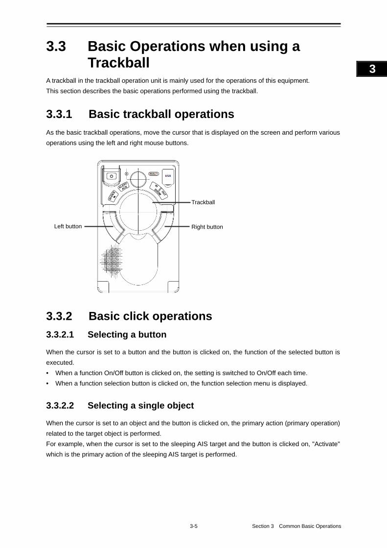
3-5 Section 3 Common Basic Operations
1
2
3
4
5
6
7
8
9
10
11
12
13
14
15
16
17
18
19
20
21
22
23
24
25
APP A
APP B
1
3.3 Basic Operations when using a Trackball
A trackball in the trackball operation unit is mainly used for the operations of this equipment.
This section describes the basic operations performed using the trackball.
3.3.1 Basic trackball operations
As the basic trackball operations, move the cursor that is displayed on the screen and perform various
operations using the left and right mouse buttons.
3.3.2 Basic click operations
3.3.2.1 Selecting a button
When the cursor is set to a button and the button is clicked on, the function of the selected button is
executed.
• When a function On/Off button is clicked on, the setting is switched to On/Off each time.
• When a function selection button is clicked on, the function selection menu is displayed.
3.3.2.2 Selecting a single object
When the cursor is set to an object and the button is clicked on, the primary action (primary operation)
related to the target object is performed.
For example, when the cursor is set to the sleeping AIS target and the button is clicked on, "Activate"
which is the primary action of the sleeping AIS target is performed.
Right button Left button
Trackball
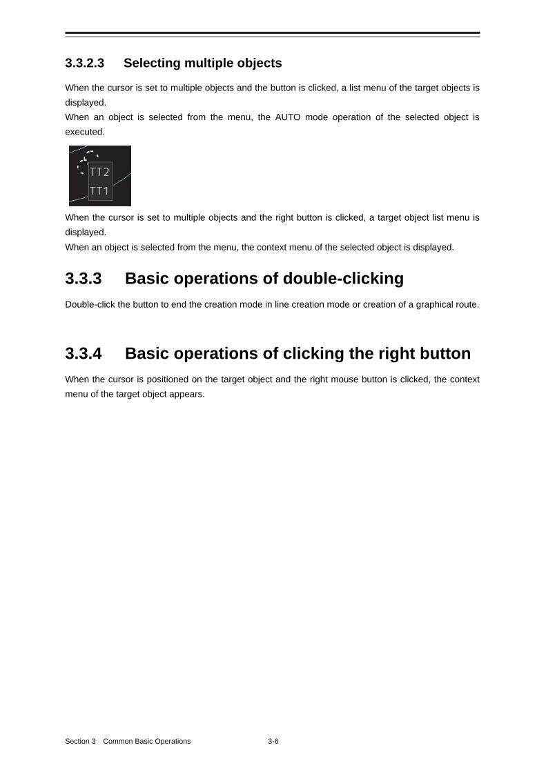
Section 3 Common Basic Operations 3-6
3.3.2.3 Selecting multiple objects
When the cursor is set to multiple objects and the button is clicked, a list menu of the target objects is
displayed.
When an object is selected from the menu, the AUTO mode operation of the selected object is
executed.
When the cursor is set to multiple objects and the right button is clicked, a target object list menu is
displayed.
When an object is selected from the menu, the context menu of the selected object is displayed.
3.3.3 Basic operations of double-clicking
Double-click the button to end the creation mode in line creation mode or creation of a graphical route.
3.3.4 Basic operations of clicking the right button
When the cursor is positioned on the target object and the right mouse button is clicked, the context
menu of the target object appears.
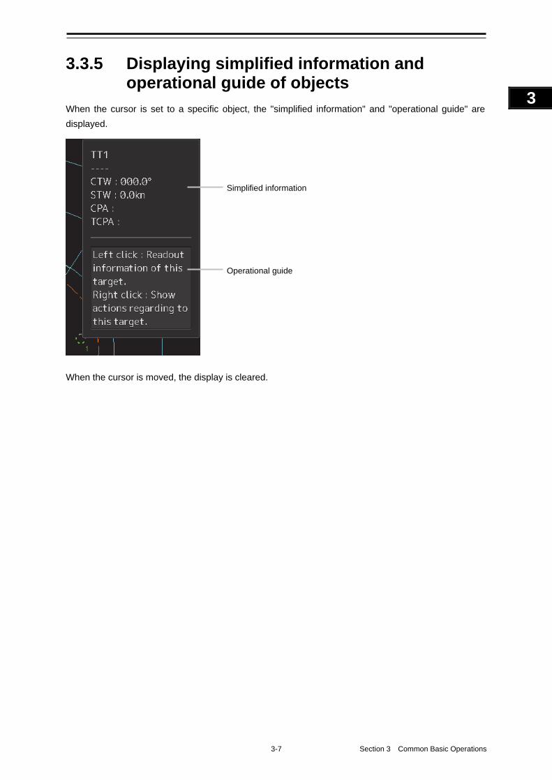
3-7 Section 3 Common Basic Operations
1
2
3
4
5
6
7
8
9
10
11
12
13
14
15
16
17
18
19
20
21
22
23
24
25
APP A
APP B
1
3.3.5 Displaying simplified information and operational guide of objects
When the cursor is set to a specific object, the "simplified information" and "operational guide" are
displayed.
When the cursor is moved, the display is cleared.
Simplified information
Operational guide
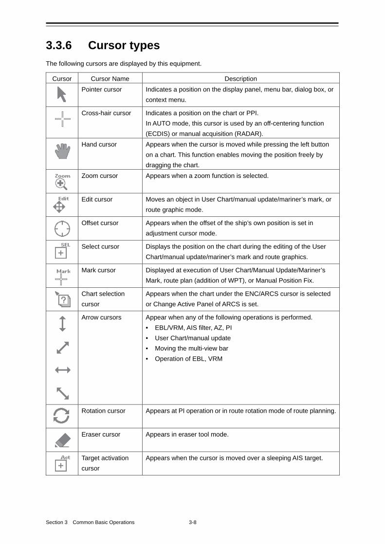
Section 3 Common Basic Operations 3-8
3.3.6 Cursor types
The following cursors are displayed by this equipment.
Cursor Cursor Name Description
Pointer cursor Indicates a position on the display panel, menu bar, dialog box, or
context menu.
Cross-hair cursor Indicates a position on the chart or PPI.
In AUTO mode, this cursor is used by an off-centering function
(ECDIS) or manual acquisition (RADAR).
Hand cursor Appears when the cursor is moved while pressing the left button
on a chart. This function enables moving the position freely by
dragging the chart.
Zoom cursor Appears when a zoom function is selected.
Edit cursor Moves an object in User Chart/manual update/mariner’s mark, or
route graphic mode.
Offset cursor Appears when the offset of the ship’s own position is set in
adjustment cursor mode.
Select cursor Displays the position on the chart during the editing of the User
Chart/manual update/mariner’s mark and route graphics.
Mark cursor Displayed at execution of User Chart/Manual Update/Mariner’s
Mark, route plan (addition of WPT), or Manual Position Fix.
Chart selection
cursor
Appears when the chart under the ENC/ARCS cursor is selected
or Change Active Panel of ARCS is set.
Arrow cursors Appear when any of the following operations is performed.
• EBL/VRM, AIS filter, AZ, PI
• User Chart/manual update
• Moving the multi-view bar
• Operation of EBL, VRM
Rotation cursor Appears at PI operation or in route rotation mode of route planning.
Eraser cursor Appears in eraser tool mode.
Target activation
cursor
Appears when the cursor is moved over a sleeping AIS target.
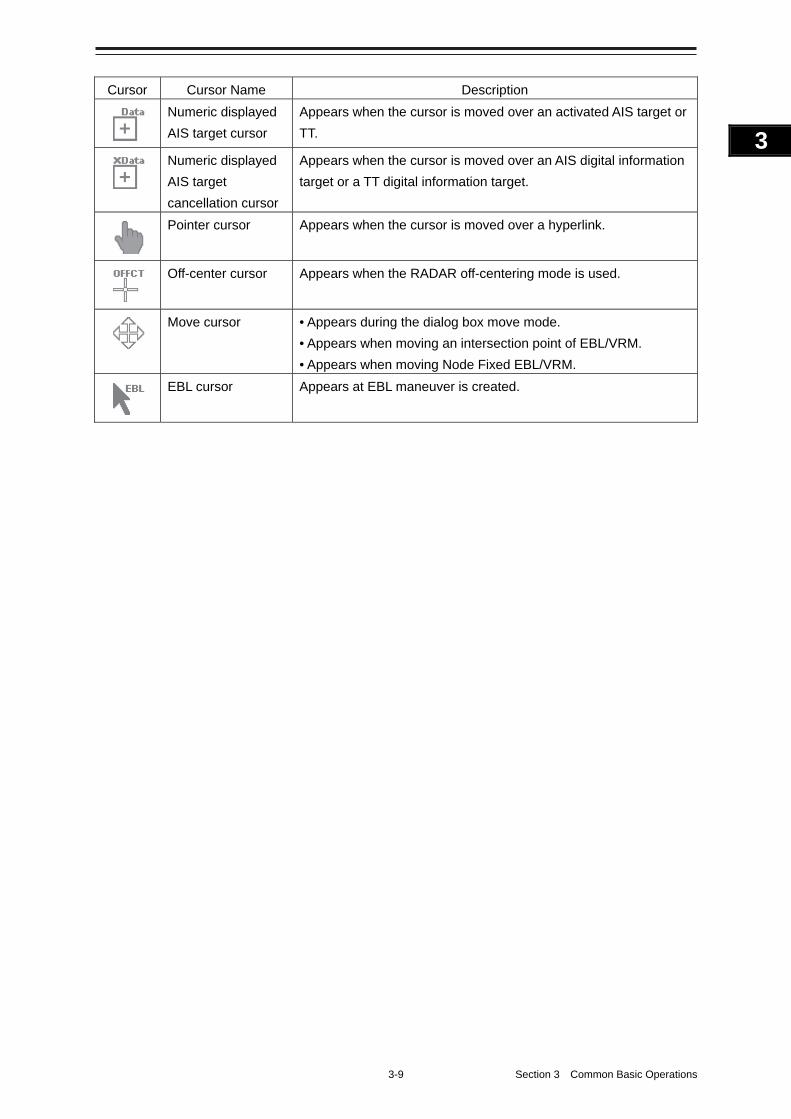
3-9 Section 3 Common Basic Operations
1
2
3
4
5
6
7
8
9
10
11
12
13
14
15
16
17
18
19
20
21
22
23
24
25
APP A
APP B
1
Cursor Cursor Name Description
Numeric displayed
AIS target cursor
Appears when the cursor is moved over an activated AIS target or
TT.
Numeric displayed
AIS target
cancellation cursor
Appears when the cursor is moved over an AIS digital information
target or a TT digital information target.
Pointer cursor Appears when the cursor is moved over a hyperlink.
Off-center cursor Appears when the RADAR off-centering mode is used.
Move cursor • Appears during the dialog box move mode.
• Appears when moving an intersection point of EBL/VRM.
• Appears when moving Node Fixed EBL/VRM.
EBL cursor Appears at EBL maneuver is created.
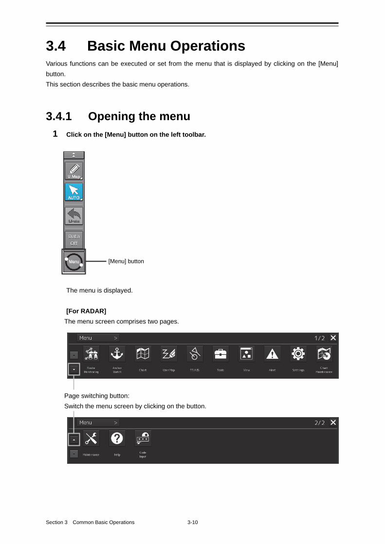
Section 3 Common Basic Operations 3-10
3.4 Basic Menu Operations Various functions can be executed or set from the menu that is displayed by clicking on the [Menu]
button.
This section describes the basic menu operations.
3.4.1 Opening the menu
1 Click on the [Menu] button on the left toolbar.
The menu is displayed.
[For RADAR]
The menu screen comprises two pages.
Page switching button:
Switch the menu screen by clicking on the button.
[Menu] button
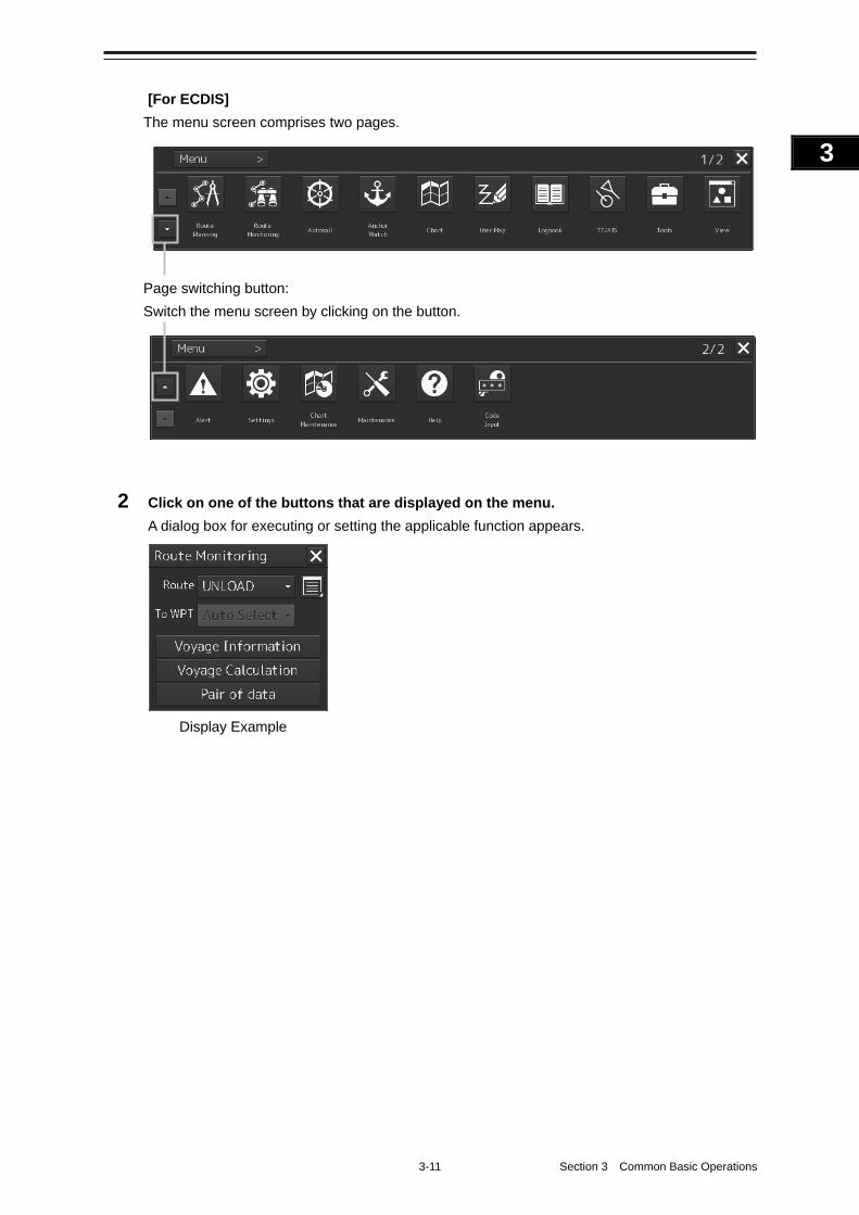
3-11 Section 3 Common Basic Operations
1
2
3
4
5
6
7
8
9
10
11
12
13
14
15
16
17
18
19
20
21
22
23
24
25
APP A
APP B
1
[For ECDIS]
The menu screen comprises two pages.
Page switching button:
Switch the menu screen by clicking on the button.
2 Click on one of the buttons that are displayed on the menu.
A dialog box for executing or setting the applicable function appears.
Display Example
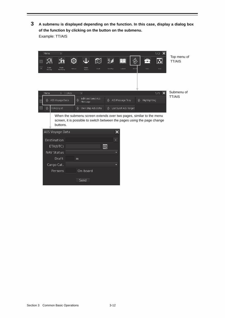
Section 3 Common Basic Operations 3-12
3 A submenu is displayed depending on the function. In this case, display a dialog box
of the function by clicking on the button on the submenu.
Example: TT/AIS
Top menu of TT/AIS
Submenu of TT/AIS
When the submenu screen extends over two pages, similar to the menu screen, it is possible to switch between the pages using the page change buttons.
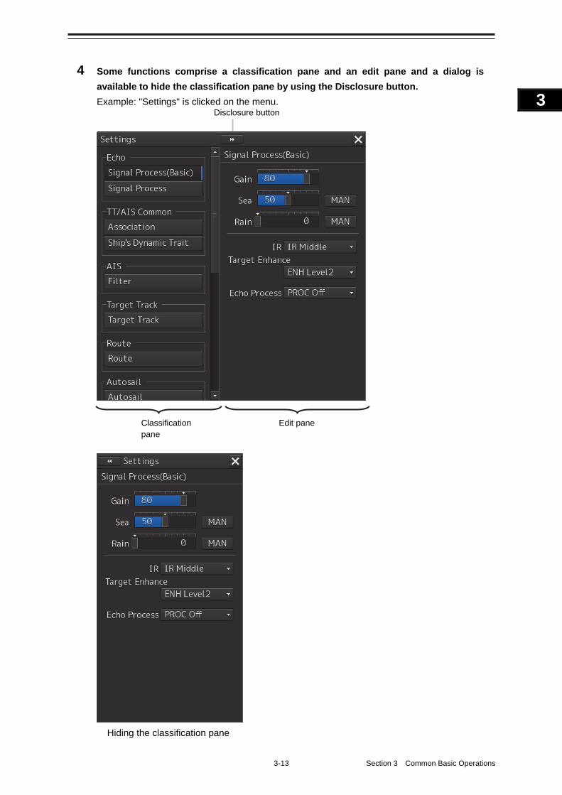
3-13 Section 3 Common Basic Operations
1
2
3
4
5
6
7
8
9
10
11
12
13
14
15
16
17
18
19
20
21
22
23
24
25
APP A
APP B
1
4 Some functions comprise a classification pane and an edit pane and a dialog is
available to hide the classification pane by using the Disclosure button.
Example: "Settings" is clicked on the menu.
Hiding the classification pane
Disclosure button
Classification pane
Edit pane
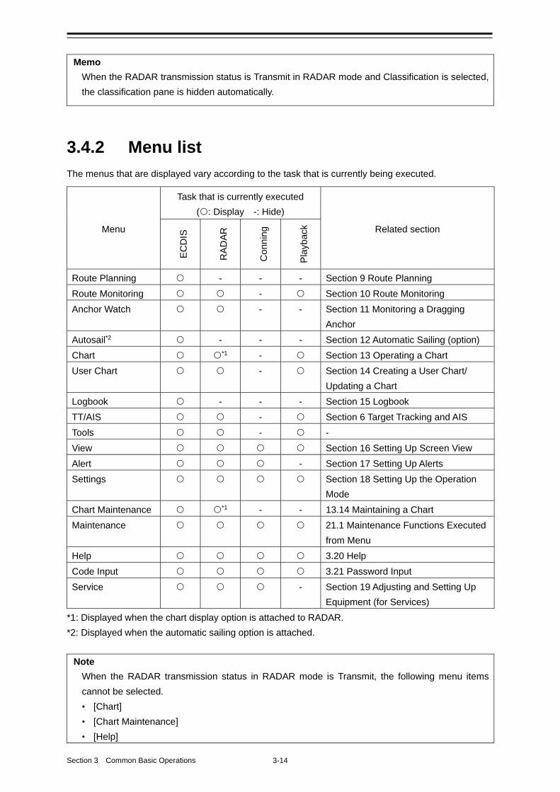
Section 3 Common Basic Operations 3-14
Memo
When the RADAR transmission status is Transmit in RADAR mode and Classification is selected,
the classification pane is hidden automatically.
3.4.2 Menu list
The menus that are displayed vary according to the task that is currently being executed.
Menu
Task that is currently executed
(: Display -: Hide)
Related section
EC
DIS
RA
DA
R
Con
ning
Pla
ybac
k
Route Planning - - - Section 9 Route Planning
Route Monitoring - Section 10 Route Monitoring
Anchor Watch - - Section 11 Monitoring a Dragging
Anchor
Autosail*2 - - - Section 12 Automatic Sailing (option)
Chart *1 - Section 13 Operating a Chart
User Chart - Section 14 Creating a User Chart/
Updating a Chart
Logbook - - - Section 15 Logbook
TT/AIS - Section 6 Target Tracking and AIS
Tools - -
View Section 16 Setting Up Screen View
Alert - Section 17 Setting Up Alerts
Settings Section 18 Setting Up the Operation
Mode
Chart Maintenance *1 - - 13.14 Maintaining a Chart
Maintenance 21.1 Maintenance Functions Executed
from Menu
Help 3.20 Help
Code Input 3.21 Password Input
Service - Section 19 Adjusting and Setting Up
Equipment (for Services)
*1: Displayed when the chart display option is attached to RADAR.
*2: Displayed when the automatic sailing option is attached.
Note
When the RADAR transmission status in RADAR mode is Transmit, the following menu items
cannot be selected.
• [Chart]
• [Chart Maintenance]
• [Help]
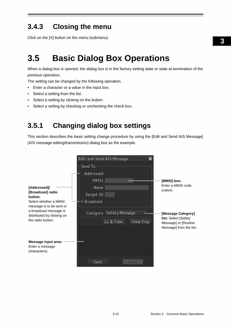
3-15 Section 3 Common Basic Operations
1
2
3
4
5
6
7
8
9
10
11
12
13
14
15
16
17
18
19
20
21
22
23
24
25
APP A
APP B
1
3.4.3 Closing the menu
Click on the [X] button on the menu (submenu).
3.5 Basic Dialog Box Operations When a dialog box is opened, the dialog box is in the factory setting state or state at termination of the
previous operation.
The setting can be changed by the following operation.
• Enter a character or a value in the input box.
• Select a setting from the list.
• Select a setting by clicking on the button.
• Select a setting by checking or unchecking the check box.
3.5.1 Changing dialog box settings
This section describes the basic setting change procedure by using the [Edit and Send AIS Message]
(AIS message editing/transmission) dialog box as the example.
[Addressed]/ [Broadcast] radio button: Select whether a MMSI message is to be sent or a broadcast message is distributed by clicking on the radio button.
Message input area: Enter a message (characters).
[MMSI] box: Enter a MMSI code (value).
[Message Category] list: Select [Safety Message] or [Routine Message] from the list.
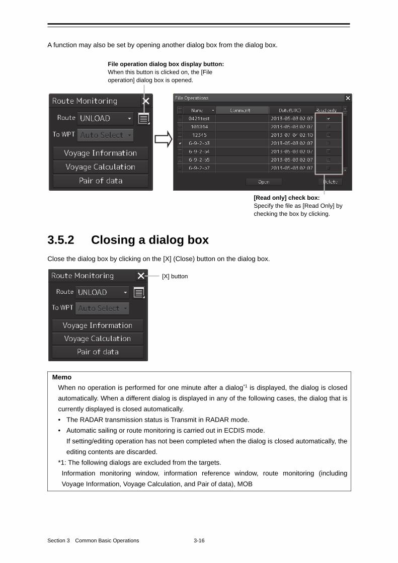
Section 3 Common Basic Operations 3-16
A function may also be set by opening another dialog box from the dialog box.
3.5.2 Closing a dialog box
Close the dialog box by clicking on the [X] (Close) button on the dialog box.
Memo
When no operation is performed for one minute after a dialog*1 is displayed, the dialog is closed
automatically. When a different dialog is displayed in any of the following cases, the dialog that is
currently displayed is closed automatically.
• The RADAR transmission status is Transmit in RADAR mode.
• Automatic sailing or route monitoring is carried out in ECDIS mode.
If setting/editing operation has not been completed when the dialog is closed automatically, the
editing contents are discarded.
*1: The following dialogs are excluded from the targets.
Information monitoring window, information reference window, route monitoring (including
Voyage Information, Voyage Calculation, and Pair of data), MOB
[X] button
[Read only] check box: Specify the file as [Read Only] by checking the box by clicking.
File operation dialog box display button: When this button is clicked on, the [File operation] dialog box is opened.
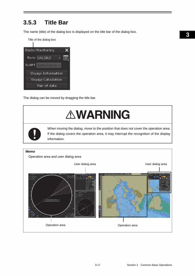
3-17 Section 3 Common Basic Operations
1
2
3
4
5
6
7
8
9
10
11
12
13
14
15
16
17
18
19
20
21
22
23
24
25
APP A
APP B
1
3.5.3 Title Bar
The name (title) of the dialog box is displayed on the title bar of the dialog box.
The dialog can be moved by dragging the title bar.
When moving the dialog, move to the position that does not cover the operation area.
If the dialog covers the operation area, it may interrupt the recognition of the display
information.
Memo
Operation area and user dialog area
Title of the dialog box
Operation area Operation area
User dialog area User dialog area
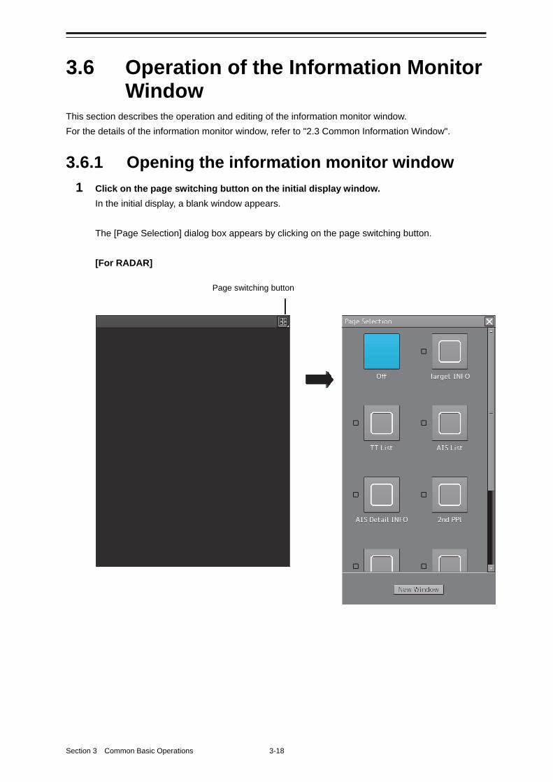
Section 3 Common Basic Operations 3-18
3.6 Operation of the Information Monitor Window
This section describes the operation and editing of the information monitor window.
For the details of the information monitor window, refer to "2.3 Common Information Window".
3.6.1 Opening the information monitor window
1 Click on the page switching button on the initial display window.
In the initial display, a blank window appears.
The [Page Selection] dialog box appears by clicking on the page switching button.
[For RADAR]
Page switching button
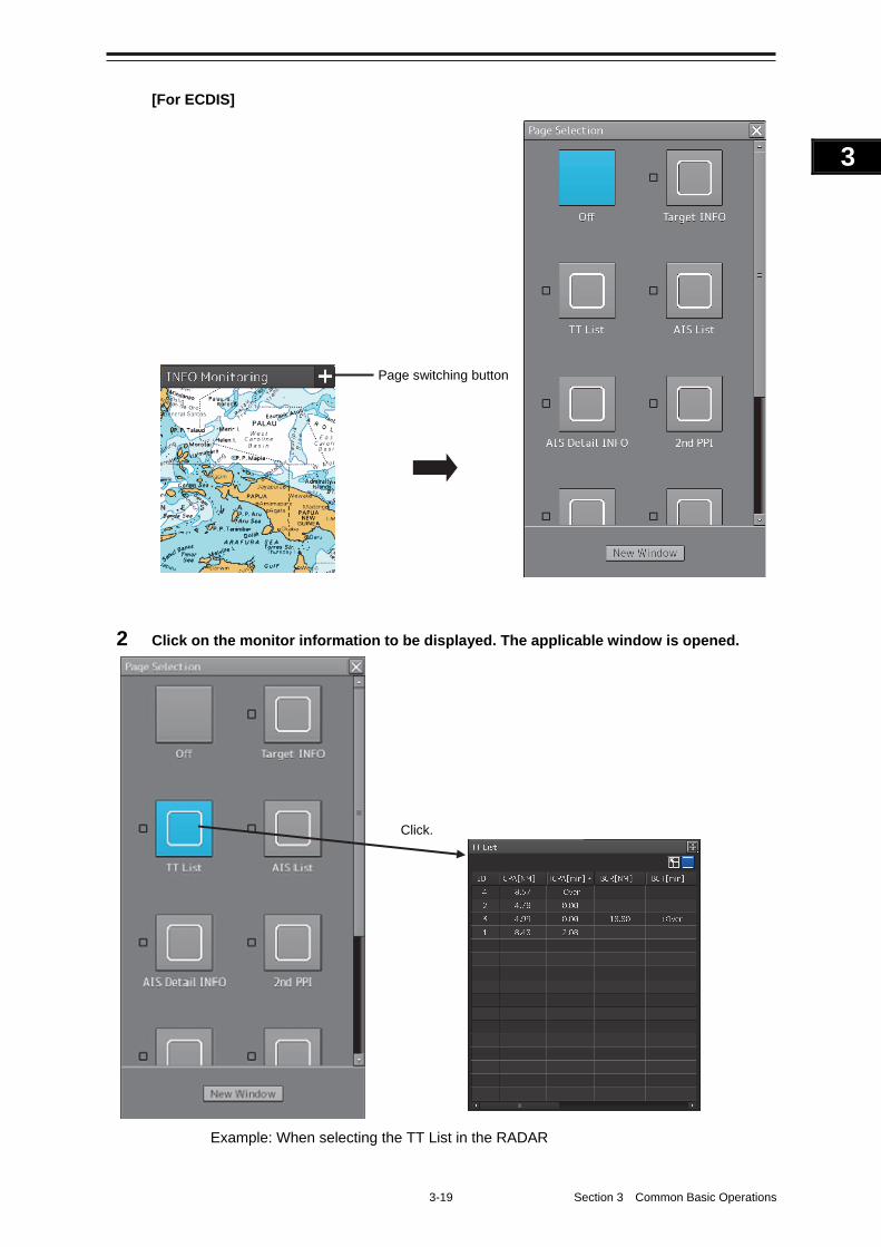
3-19 Section 3 Common Basic Operations
1
2
3
4
5
6
7
8
9
10
11
12
13
14
15
16
17
18
19
20
21
22
23
24
25
APP A
APP B
1
[For ECDIS]
2 Click on the monitor information to be displayed. The applicable window is opened.
Example: When selecting the TT List in the RADAR
Click.
Page switching button
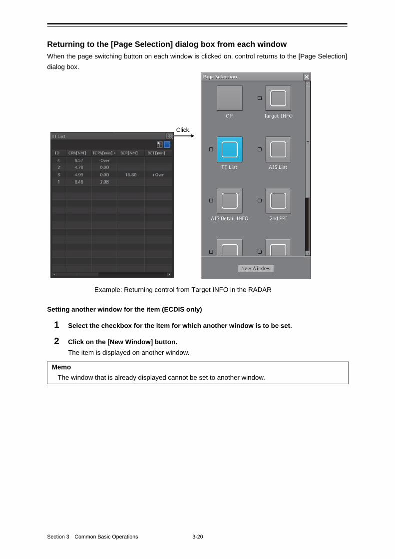
Section 3 Common Basic Operations 3-20
Returning to the [Page Selection] dialog box from each window
When the page switching button on each window is clicked on, control returns to the [Page Selection]
dialog box.
Setting another window for the item (ECDIS only)
1 Select the checkbox for the item for which another window is to be set.
2 Click on the [New Window] button.
The item is displayed on another window.
Memo
The window that is already displayed cannot be set to another window.
Example: Returning control from Target INFO in the RADAR
Click.
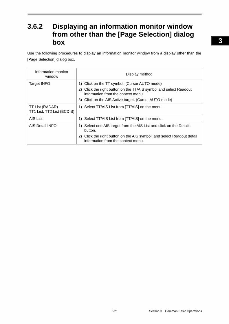
3-21 Section 3 Common Basic Operations
1
2
3
4
5
6
7
8
9
10
11
12
13
14
15
16
17
18
19
20
21
22
23
24
25
APP A
APP B
1
3.6.2 Displaying an information monitor window from other than the [Page Selection] dialog box
Use the following procedures to display an information monitor window from a display other than the
[Page Selection] dialog box.
Information monitor window
Display method
Target INFO 1) Click on the TT symbol. (Cursor AUTO mode)
2) Click the right button on the TT/AIS symbol and select Readout information from the context menu.
3) Click on the AIS Active target. (Cursor AUTO mode)
TT List (RADAR) TT1 List, TT2 List (ECDIS)
1) Select TT/AIS List from [TT/AIS] on the menu.
AIS List 1) Select TT/AIS List from [TT/AIS] on the menu.
AIS Detail INFO 1) Select one AIS target from the AIS List and click on the Details button.
2) Click the right button on the AIS symbol, and select Readout detail information from the context menu.
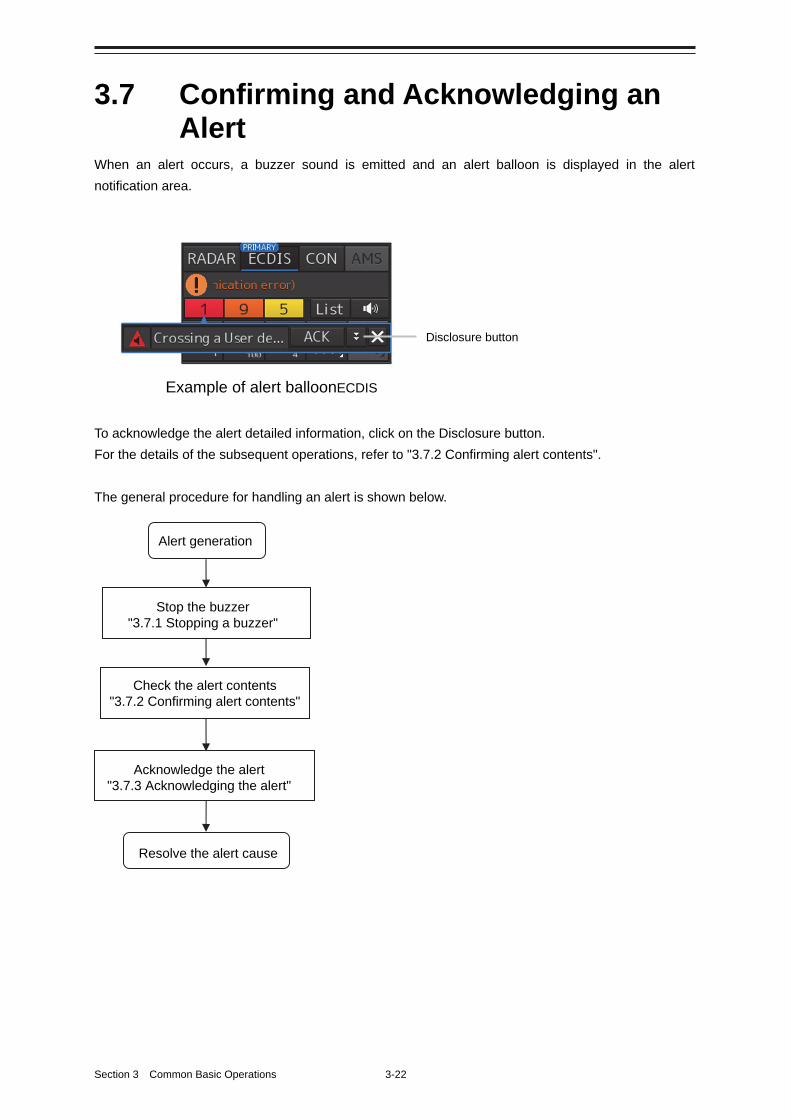
Section 3 Common Basic Operations 3-22
3.7 Confirming and Acknowledging an Alert
When an alert occurs, a buzzer sound is emitted and an alert balloon is displayed in the alert
notification area.
To acknowledge the alert detailed information, click on the Disclosure button.
For the details of the subsequent operations, refer to "3.7.2 Confirming alert contents".
The general procedure for handling an alert is shown below.
Alert generation
Stop the buzzer "3.7.1 Stopping a buzzer"
Acknowledge the alert "3.7.3 Acknowledging the alert"
Check the alert contents "3.7.2 Confirming alert contents"
Resolve the alert cause
Disclosure button
Example of alert balloonECDIS
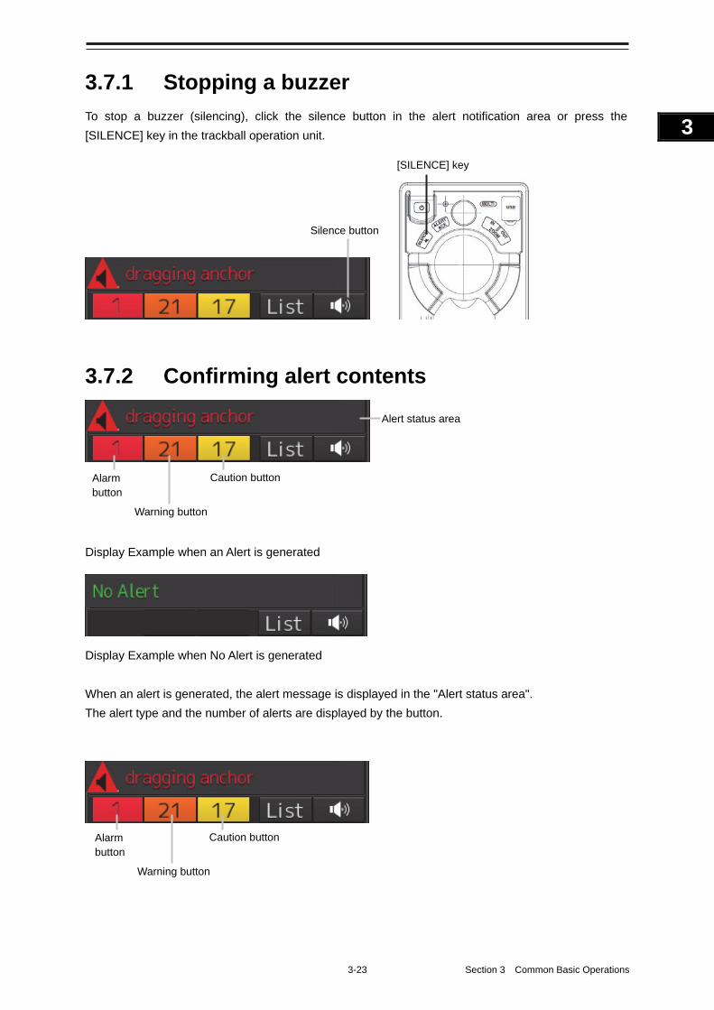
3-23 Section 3 Common Basic Operations
1
2
3
4
5
6
7
8
9
10
11
12
13
14
15
16
17
18
19
20
21
22
23
24
25
APP A
APP B
1
3.7.1 Stopping a buzzer
To stop a buzzer (silencing), click the silence button in the alert notification area or press the
[SILENCE] key in the trackball operation unit.
3.7.2 Confirming alert contents
Display Example when an Alert is generated
Display Example when No Alert is generated
When an alert is generated, the alert message is displayed in the "Alert status area".
The alert type and the number of alerts are displayed by the button.
[SILENCE] key
Silence button
Warning button
Alert status area
Caution button Alarm button
Warning button
Caution button Alarm button
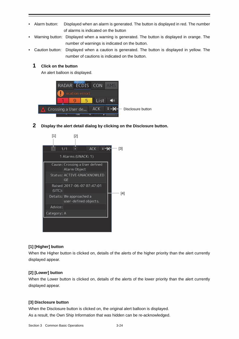
Section 3 Common Basic Operations 3-24
• Alarm button: Displayed when an alarm is generated. The button is displayed in red. The number
of alarms is indicated on the button
• Warning button: Displayed when a warning is generated. The button is displayed in orange. The
number of warnings is indicated on the button.
• Caution button: Displayed when a caution is generated. The button is displayed in yellow. The
number of cautions is indicated on the button.
1 Click on the button
An alert balloon is displayed.
2 Display the alert detail dialog by clicking on the Disclosure button.
[1] [Higher] button
When the Higher button is clicked on, details of the alerts of the higher priority than the alert currently
displayed appear.
[2] [Lower] button
When the Lower button is clicked on, details of the alerts of the lower priority than the alert currently
displayed appear.
[3] Disclosure button
When the Disclosure button is clicked on, the original alert balloon is displayed.
As a result, the Own Ship Information that was hidden can be re-acknowledged.
Disclosure button
[1] [2]
[3]
[4]

3-25 Section 3 Common Basic Operations
1
2
3
4
5
6
7
8
9
10
11
12
13
14
15
16
17
18
19
20
21
22
23
24
25
APP A
APP B
1
[4] Detail information
Cause (cause), status (Status), date and time (Raised), details (Details), action (Advice) and Category
to be taken are displayed.
Memo
About Information:
Information is displayed in addition to a warning or a caution in the alert status area.
Information is used to report operation errors and so on to the users.
Unlike other alerts, no detail display is provided for Information.
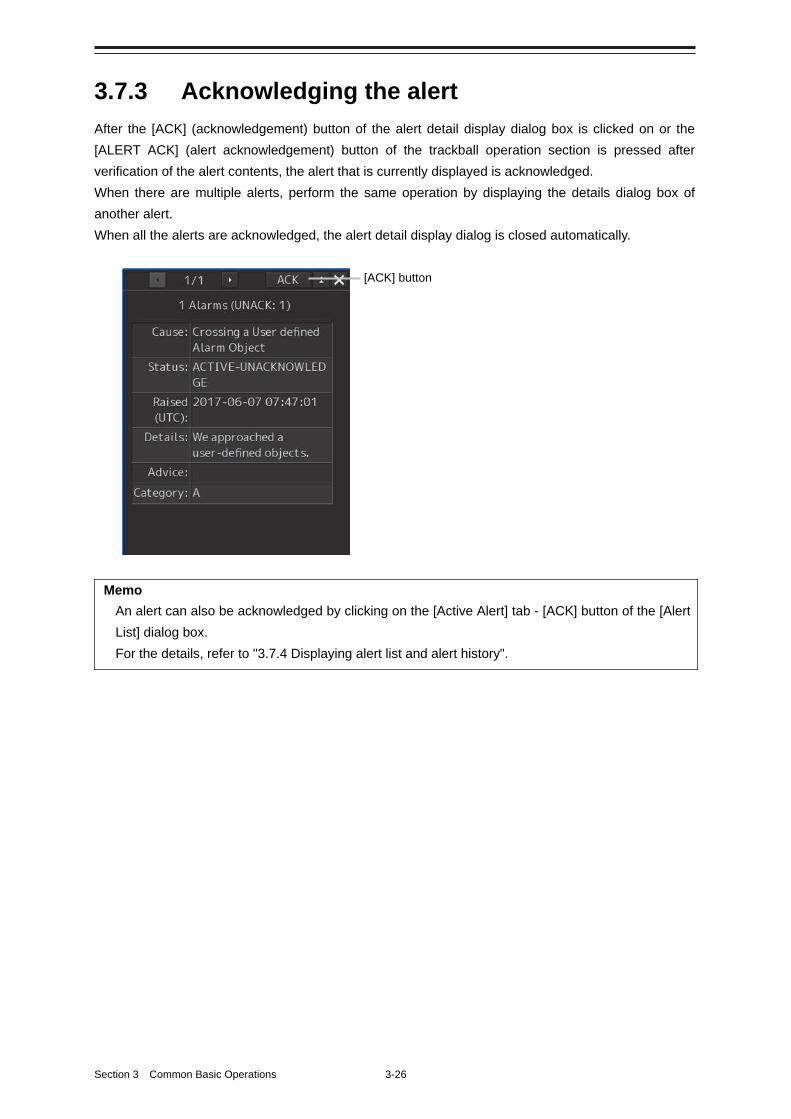
Section 3 Common Basic Operations 3-26
3.7.3 Acknowledging the alert
After the [ACK] (acknowledgement) button of the alert detail display dialog box is clicked on or the
[ALERT ACK] (alert acknowledgement) button of the trackball operation section is pressed after
verification of the alert contents, the alert that is currently displayed is acknowledged.
When there are multiple alerts, perform the same operation by displaying the details dialog box of
another alert.
When all the alerts are acknowledged, the alert detail display dialog is closed automatically.
Memo
An alert can also be acknowledged by clicking on the [Active Alert] tab - [ACK] button of the [Alert
List] dialog box.
For the details, refer to "3.7.4 Displaying alert list and alert history".
[ACK] button
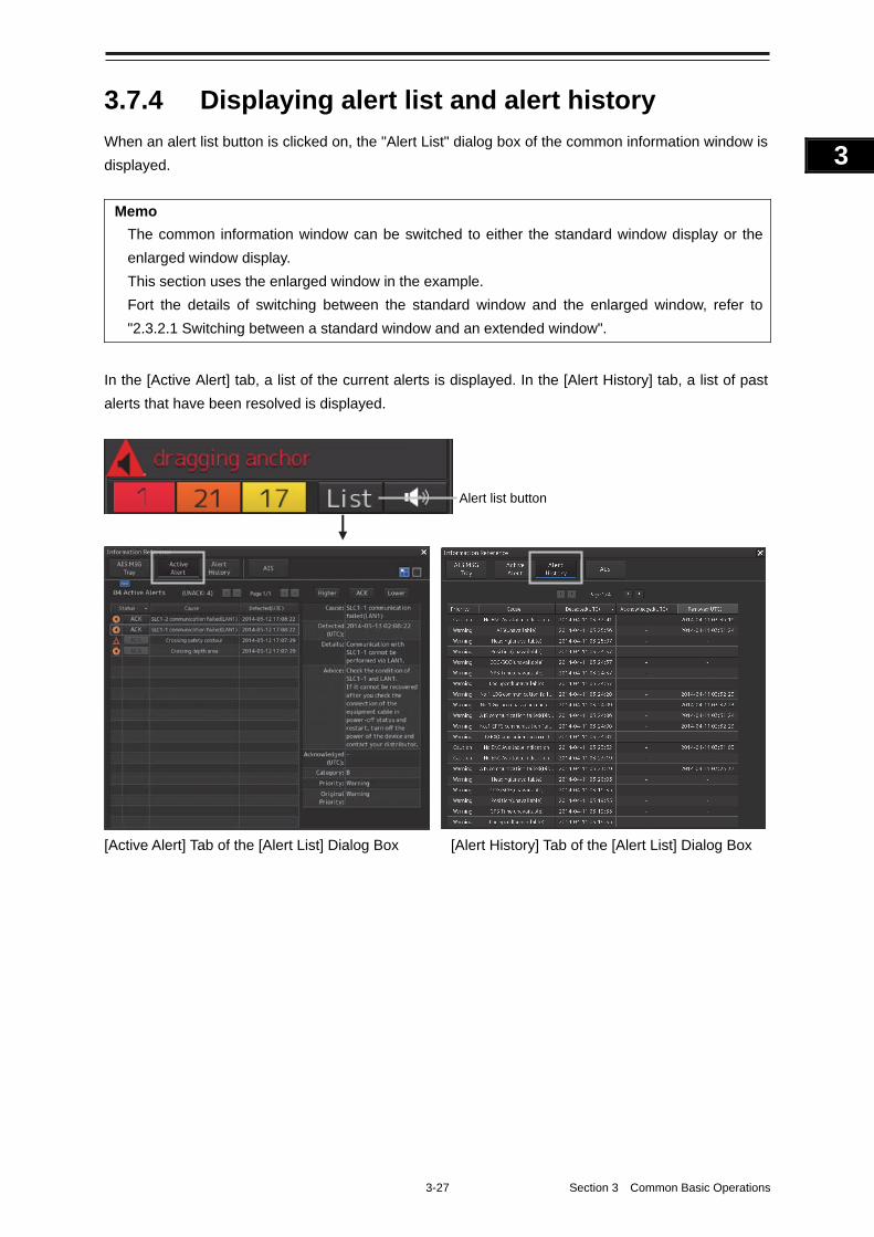
3-27 Section 3 Common Basic Operations
1
2
3
4
5
6
7
8
9
10
11
12
13
14
15
16
17
18
19
20
21
22
23
24
25
APP A
APP B
1
3.7.4 Displaying alert list and alert history
When an alert list button is clicked on, the "Alert List" dialog box of the common information window is
displayed.
Memo
The common information window can be switched to either the standard window display or the
enlarged window display.
This section uses the enlarged window in the example.
Fort the details of switching between the standard window and the enlarged window, refer to
"2.3.2.1 Switching between a standard window and an extended window".
In the [Active Alert] tab, a list of the current alerts is displayed. In the [Alert History] tab, a list of past
alerts that have been resolved is displayed.
[Active Alert] Tab of the [Alert List] Dialog Box [Alert History] Tab of the [Alert List] Dialog Box
Alert list button
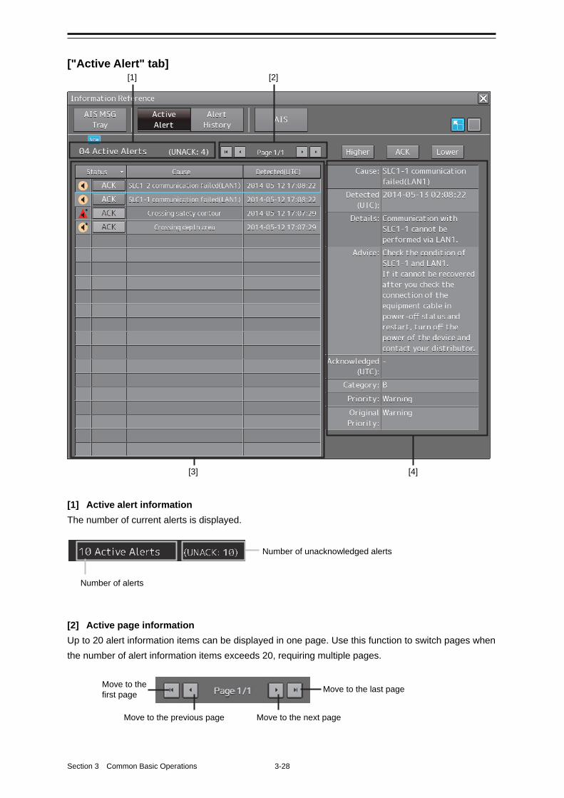
Section 3 Common Basic Operations 3-28
["Active Alert" tab]
[1] Active alert information
The number of current alerts is displayed.
[2] Active page information
Up to 20 alert information items can be displayed in one page. Use this function to switch pages when
the number of alert information items exceeds 20, requiring multiple pages.
Move to the first page Move to the last page
Move to the previous page Move to the next page
Number of alerts
Number of unacknowledged alerts
[1]
[4]
[2]
[3]
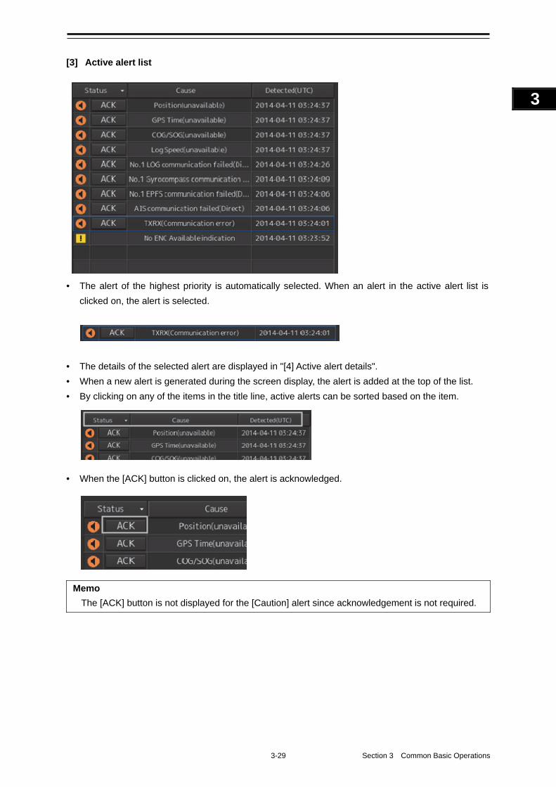
3-29 Section 3 Common Basic Operations
1
2
3
4
5
6
7
8
9
10
11
12
13
14
15
16
17
18
19
20
21
22
23
24
25
APP A
APP B
1
[3] Active alert list
• The alert of the highest priority is automatically selected. When an alert in the active alert list is
clicked on, the alert is selected.
• The details of the selected alert are displayed in "[4] Active alert details".
• When a new alert is generated during the screen display, the alert is added at the top of the list.
• By clicking on any of the items in the title line, active alerts can be sorted based on the item.
• When the [ACK] button is clicked on, the alert is acknowledged.
Memo
The [ACK] button is not displayed for the [Caution] alert since acknowledgement is not required.
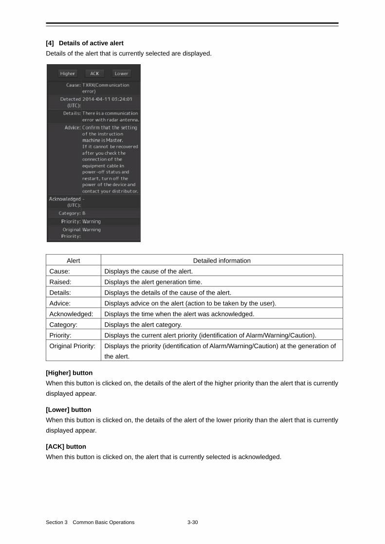
Section 3 Common Basic Operations 3-30
[4] Details of active alert
Details of the alert that is currently selected are displayed.
Alert Detailed information
Cause: Displays the cause of the alert.
Raised: Displays the alert generation time.
Details: Displays the details of the cause of the alert.
Advice: Displays advice on the alert (action to be taken by the user).
Acknowledged: Displays the time when the alert was acknowledged.
Category: Displays the alert category.
Priority: Displays the current alert priority (identification of Alarm/Warning/Caution).
Original Priority: Displays the priority (identification of Alarm/Warning/Caution) at the generation of
the alert.
[Higher] button
When this button is clicked on, the details of the alert of the higher priority than the alert that is currently
displayed appear.
[Lower] button
When this button is clicked on, the details of the alert of the lower priority than the alert that is currently
displayed appear.
[ACK] button
When this button is clicked on, the alert that is currently selected is acknowledged.
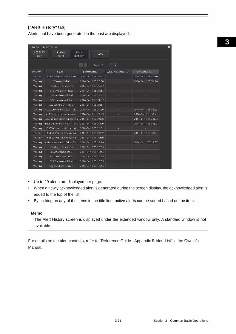
3-31 Section 3 Common Basic Operations
1
2
3
4
5
6
7
8
9
10
11
12
13
14
15
16
17
18
19
20
21
22
23
24
25
APP A
APP B
1
["Alert History" tab]
Alerts that have been generated in the past are displayed.
• Up to 20 alerts are displayed per page.
• When a newly acknowledged alert is generated during the screen display, the acknowledged alert is
added to the top of the list.
• By clicking on any of the items in the title line, active alerts can be sorted based on the item.
Memo
The Alert History screen is displayed under the extended window only. A standard window is not
available.
For details on the alert contents, refer to "Reference Guide - Appendix B Alert List" in the Owner's
Manual.
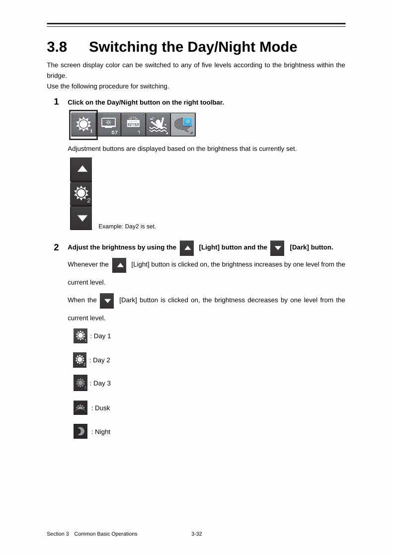
Section 3 Common Basic Operations 3-32
3.8 Switching the Day/Night Mode The screen display color can be switched to any of five levels according to the brightness within the
bridge.
Use the following procedure for switching.
1 Click on the Day/Night button on the right toolbar.
Adjustment buttons are displayed based on the brightness that is currently set.
2 Adjust the brightness by using the [Light] button and the [Dark] button.
Whenever the [Light] button is clicked on, the brightness increases by one level from the
current level.
When the [Dark] button is clicked on, the brightness decreases by one level from the
current level.
: Night
: Dusk
: Day 3
: Day 2
: Day 1
Example: Day2 is set.
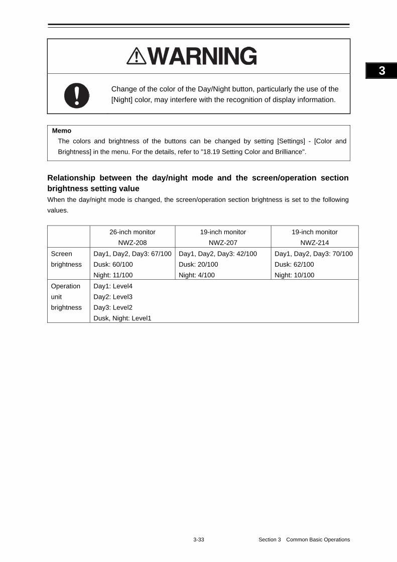
3-33 Section 3 Common Basic Operations
1
2
3
4
5
6
7
8
9
10
11
12
13
14
15
16
17
18
19
20
21
22
23
24
25
APP A
APP B
1
Change of the color of the Day/Night button, particularly the use of the
[Night] color, may interfere with the recognition of display information.
Memo
The colors and brightness of the buttons can be changed by setting [Settings] - [Color and
Brightness] in the menu. For the details, refer to "18.19 Setting Color and Brilliance".
Relationship between the day/night mode and the screen/operation section brightness setting value When the day/night mode is changed, the screen/operation section brightness is set to the following
values.
26-inch monitor
NWZ-208
19-inch monitor
NWZ-207
19-inch monitor
NWZ-214
Screen
brightness
Day1, Day2, Day3: 67/100
Dusk: 60/100
Night: 11/100
Day1, Day2, Day3: 42/100
Dusk: 20/100
Night: 4/100
Day1, Day2, Day3: 70/100
Dusk: 62/100
Night: 10/100
Operation
unit
brightness
Day1: Level4
Day2: Level3
Day3: Level2
Dusk, Night: Level1
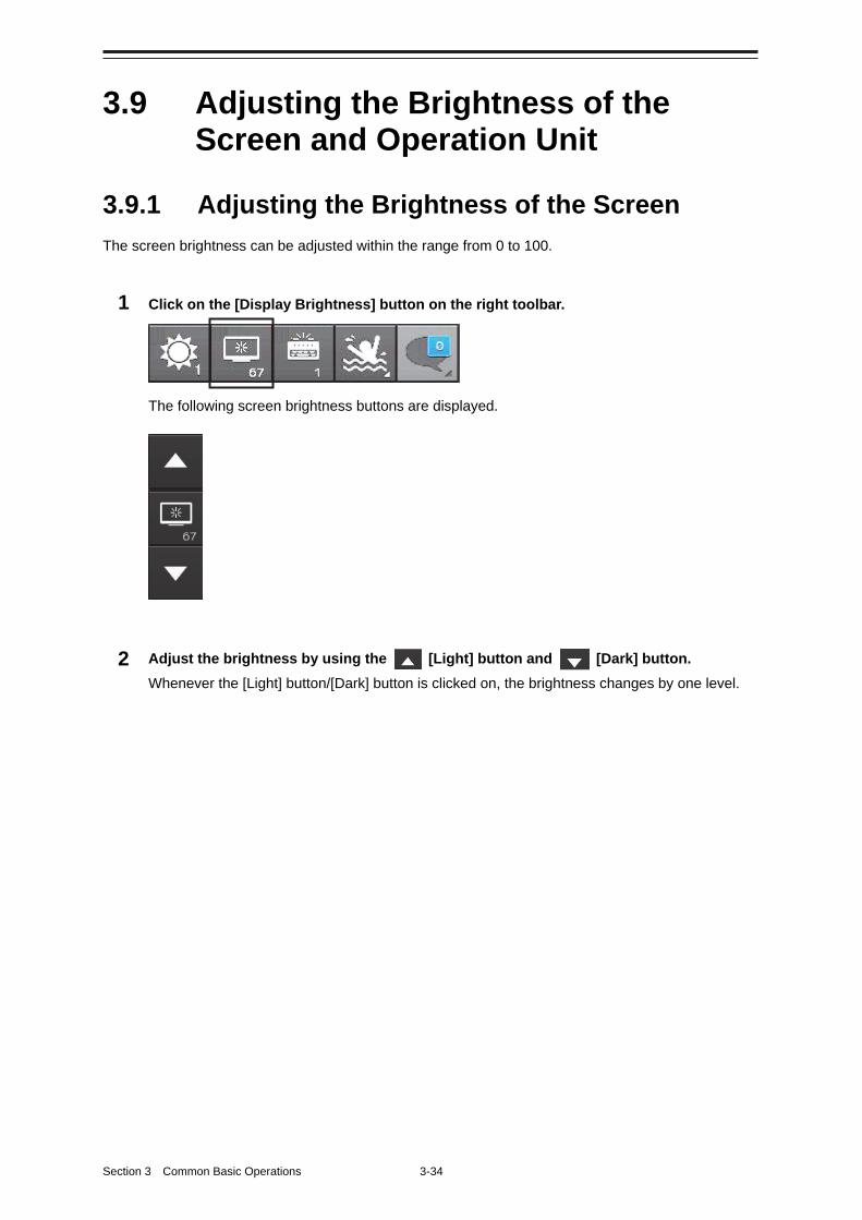
Section 3 Common Basic Operations 3-34
3.9 Adjusting the Brightness of the Screen and Operation Unit
3.9.1 Adjusting the Brightness of the Screen
The screen brightness can be adjusted within the range from 0 to 100.
1 Click on the [Display Brightness] button on the right toolbar.
The following screen brightness buttons are displayed.
2 Adjust the brightness by using the [Light] button and [Dark] button.
Whenever the [Light] button/[Dark] button is clicked on, the brightness changes by one level.
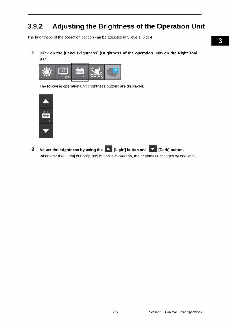
3-35 Section 3 Common Basic Operations
1
2
3
4
5
6
7
8
9
10
11
12
13
14
15
16
17
18
19
20
21
22
23
24
25
APP A
APP B
1
3.9.2 Adjusting the Brightness of the Operation Unit
The brightness of the operation section can be adjusted in 5 levels (0 to 4).
1 Click on the [Panel Brightness] (Brightness of the operation unit) on the Right Tool
Bar.
The following operation unit brightness buttons are displayed.
2 Adjust the brightness by using the [Light] button and [Dark] button.
Whenever the [Light] button/[Dark] button is clicked on, the brightness changes by one level.
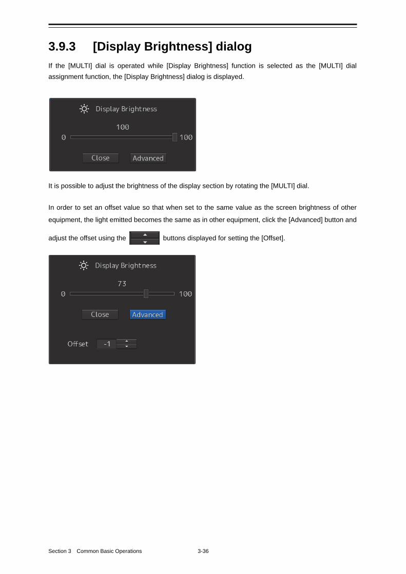
Section 3 Common Basic Operations 3-36
3.9.3 [Display Brightness] dialog
If the [MULTI] dial is operated while [Display Brightness] function is selected as the [MULTI] dial
assignment function, the [Display Brightness] dialog is displayed.
It is possible to adjust the brightness of the display section by rotating the [MULTI] dial.
In order to set an offset value so that when set to the same value as the screen brightness of other
equipment, the light emitted becomes the same as in other equipment, click the [Advanced] button and
adjust the offset using the buttons displayed for setting the [Offset].
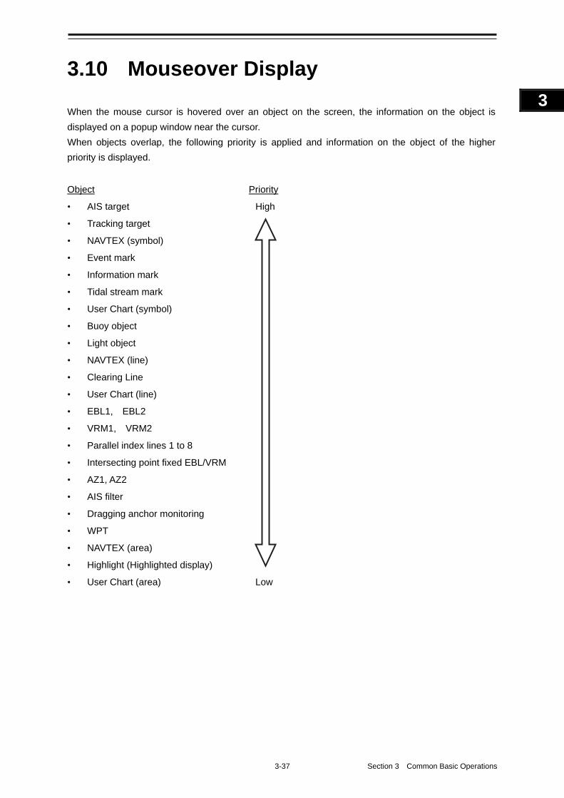
3-37 Section 3 Common Basic Operations
1
2
3
4
5
6
7
8
9
10
11
12
13
14
15
16
17
18
19
20
21
22
23
24
25
APP A
APP B
1
3.10 Mouseover Display
When the mouse cursor is hovered over an object on the screen, the information on the object is
displayed on a popup window near the cursor.
When objects overlap, the following priority is applied and information on the object of the higher
priority is displayed.
Object Priority
• AIS target High
• Tracking target
• NAVTEX (symbol)
• Event mark
• Information mark
• Tidal stream mark
• User Chart (symbol)
• Buoy object
• Light object
• NAVTEX (line)
• Clearing Line
• User Chart (line)
• EBL1, EBL2
• VRM1, VRM2
• Parallel index lines 1 to 8
• Intersecting point fixed EBL/VRM
• AZ1, AZ2
• AIS filter
• Dragging anchor monitoring
• WPT
• NAVTEX (area)
• Highlight (Highlighted display)
• User Chart (area) Low
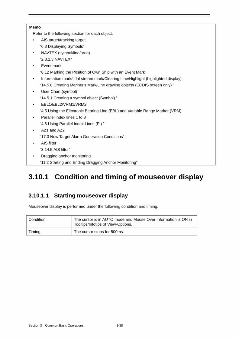
Section 3 Common Basic Operations 3-38
Memo
Refer to the following section for each object.
• AIS target/tracking target
“6.3 Displaying Symbols”
• NAVTEX (symbol/line/area)
“2.3.2.3 NAVTEX”
• Event mark
“8.12 Marking the Position of Own Ship with an Event Mark”
• Information mark/tidal stream mark/Clearing Line/Highlight (highlighted display)
“14.5.8 Creating Mariner's Mark/Line drawing objects (ECDIS screen only) ”
• User Chart (symbol)
“14.5.1 Creating a symbol object (Symbol) ”
• EBL1/EBL2/VRM1/VRM2
“4.5 Using the Electronic Bearing Line (EBL) and Variable Range Marker (VRM)
• Parallel index lines 1 to 8
“4.6 Using Parallel Index Lines (PI) ”
• AZ1 and AZ2
“17.3 New Target Alarm Generation Conditions”
• AIS filter
“3.14.5 AIS filter”
• Dragging anchor monitoring
“11.2 Starting and Ending Dragging Anchor Monitoring”
3.10.1 Condition and timing of mouseover display
3.10.1.1 Starting mouseover display
Mouseover display is performed under the following condition and timing.
Condition The cursor is in AUTO mode and Mouse Over Information is ON in Tooltips/Infotips of View-Options.
Timing The cursor stops for 500ms.
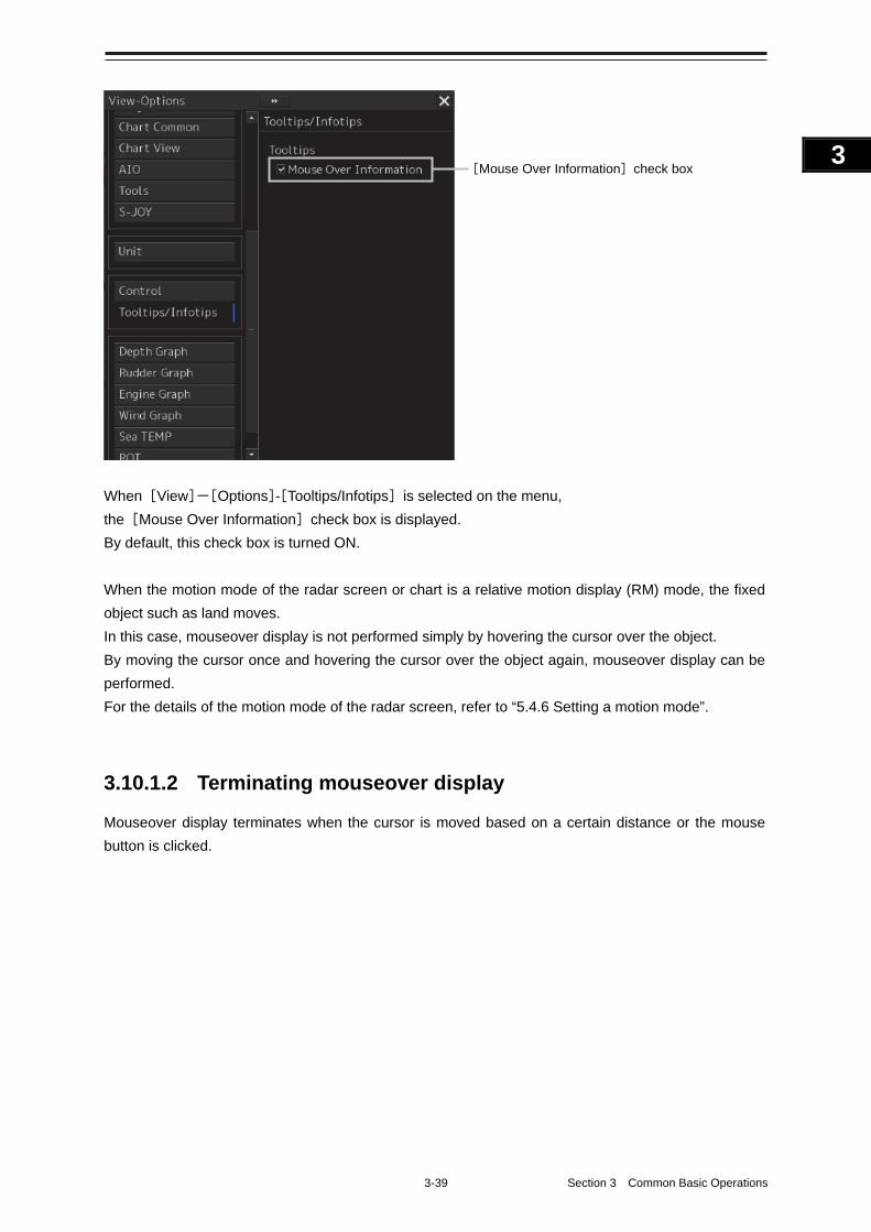
3-39 Section 3 Common Basic Operations
1
2
3
4
5
6
7
8
9
10
11
12
13
14
15
16
17
18
19
20
21
22
23
24
25
APP A
APP B
1
When [View]-[Options]-[Tooltips/Infotips] is selected on the menu,
the [Mouse Over Information] check box is displayed.
By default, this check box is turned ON.
When the motion mode of the radar screen or chart is a relative motion display (RM) mode, the fixed
object such as land moves.
In this case, mouseover display is not performed simply by hovering the cursor over the object.
By moving the cursor once and hovering the cursor over the object again, mouseover display can be
performed.
For the details of the motion mode of the radar screen, refer to “5.4.6 Setting a motion mode”.
3.10.1.2 Terminating mouseover display
Mouseover display terminates when the cursor is moved based on a certain distance or the mouse
button is clicked.
[Mouse Over Information] check box
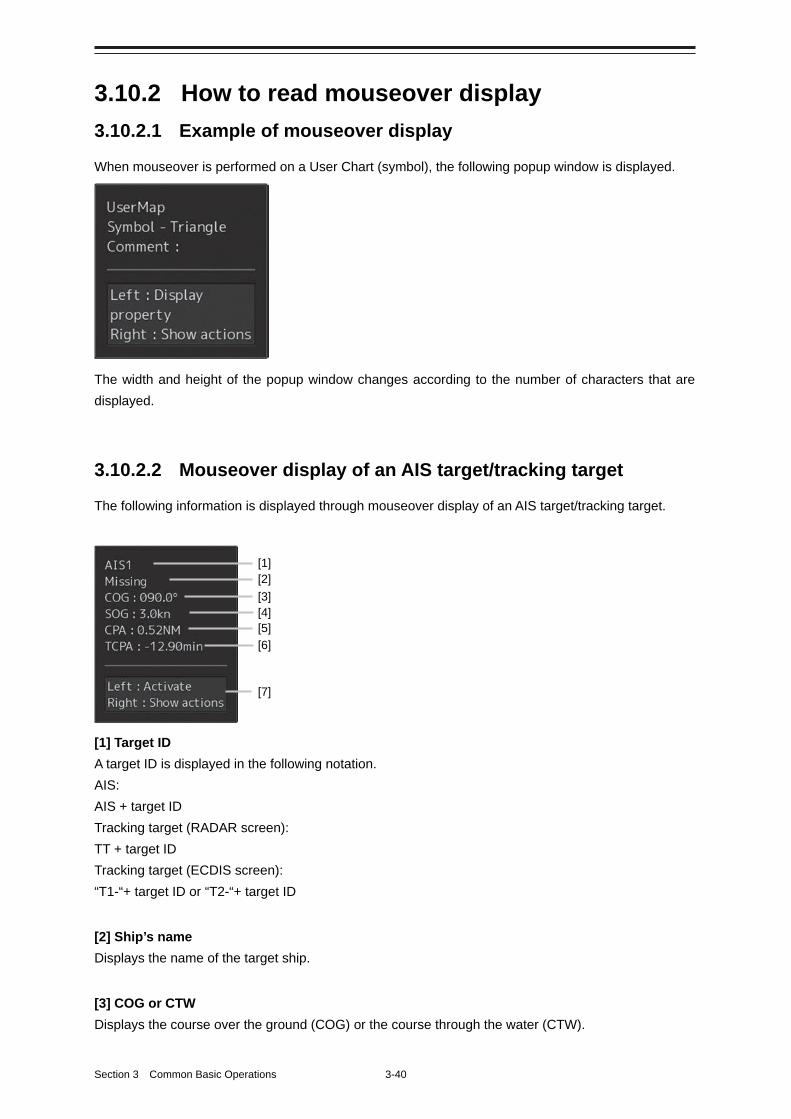
Section 3 Common Basic Operations 3-40
3.10.2 How to read mouseover display
3.10.2.1 Example of mouseover display
When mouseover is performed on a User Chart (symbol), the following popup window is displayed.
The width and height of the popup window changes according to the number of characters that are
displayed.
3.10.2.2 Mouseover display of an AIS target/tracking target
The following information is displayed through mouseover display of an AIS target/tracking target.
[1] Target ID
A target ID is displayed in the following notation.
AIS:
AIS + target ID
Tracking target (RADAR screen):
TT + target ID
Tracking target (ECDIS screen):
“T1-“+ target ID or “T2-“+ target ID
[2] Ship’s name
Displays the name of the target ship.
[3] COG or CTW
Displays the course over the ground (COG) or the course through the water (CTW).
[1] [2] [3] [4] [5] [6]
[7]
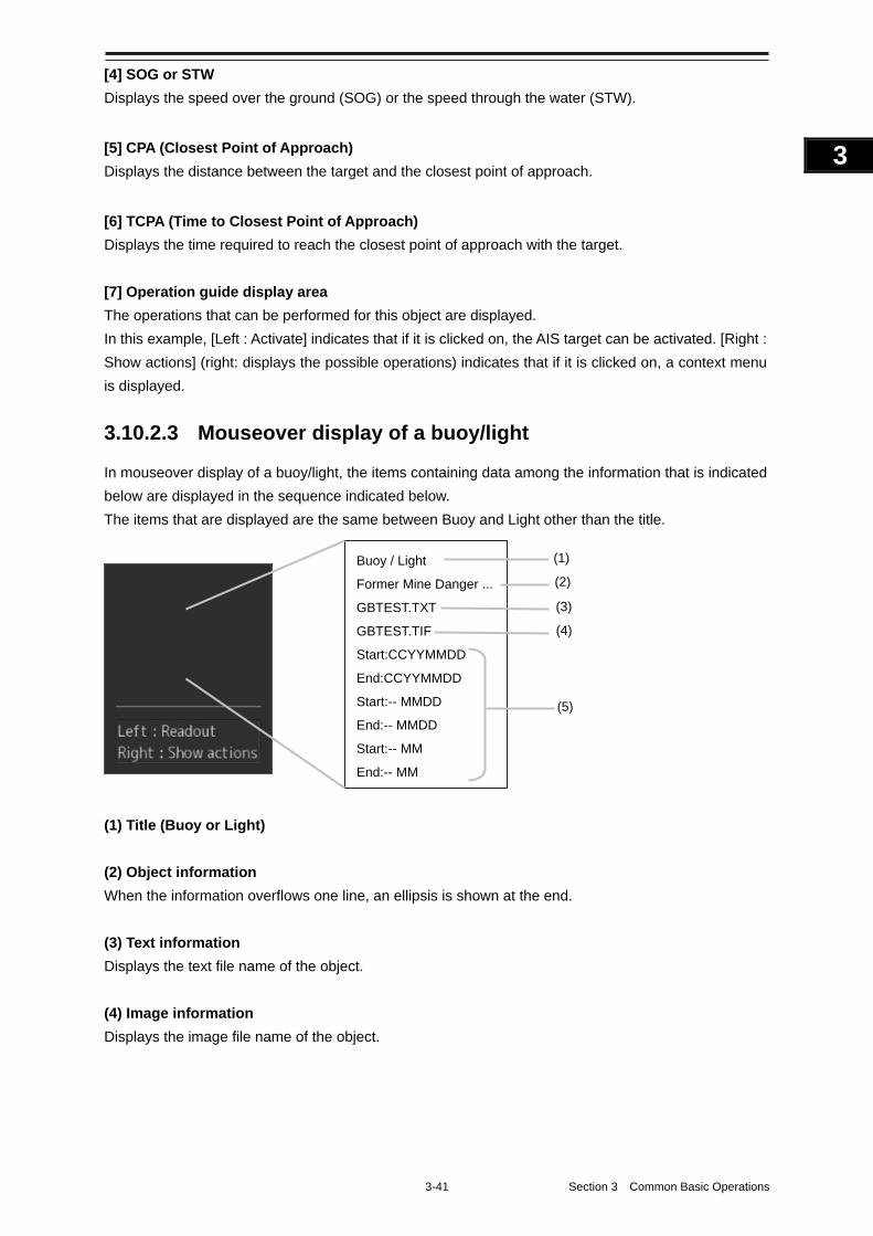
3-41 Section 3 Common Basic Operations
1
2
3
4
5
6
7
8
9
10
11
12
13
14
15
16
17
18
19
20
21
22
23
24
25
APP A
APP B
1
[4] SOG or STW
Displays the speed over the ground (SOG) or the speed through the water (STW).
[5] CPA (Closest Point of Approach)
Displays the distance between the target and the closest point of approach.
[6] TCPA (Time to Closest Point of Approach)
Displays the time required to reach the closest point of approach with the target.
[7] Operation guide display area
The operations that can be performed for this object are displayed.
In this example, [Left : Activate] indicates that if it is clicked on, the AIS target can be activated. [Right :
Show actions] (right: displays the possible operations) indicates that if it is clicked on, a context menu
is displayed.
3.10.2.3 Mouseover display of a buoy/light
In mouseover display of a buoy/light, the items containing data among the information that is indicated
below are displayed in the sequence indicated below.
The items that are displayed are the same between Buoy and Light other than the title.
(1) Title (Buoy or Light)
(2) Object information
When the information overflows one line, an ellipsis is shown at the end.
(3) Text information
Displays the text file name of the object.
(4) Image information
Displays the image file name of the object.
Buoy / Light
Former Mine Danger ...
GBTEST.TXT
GBTEST.TIF
Start:CCYYMMDD
End:CCYYMMDD
Start:-- MMDD
End:-- MMDD
Start:-- MM
End:-- MM
(1)
(2)
(3)
(4)
(5)
Section 3 Common Basic Operations 3-42
(5) Start/end for specifying the duration
Displays the start and end dates of the specified duration when an object display duration is specified.
The display formation is as follows. [In the case of CCYYMMDD] CCYY: Year MM: Month DD: Day <Display example> Start:CCYYMMDD
End:CCYYMMDD
[In the case of --MMDD] MM: Month DD: Day every year <Display example> Start:-- MMDD
End:-- MMDD
[In the case of --MM] MM: Month every year <Display example> Start:-- MM
End:-- MM
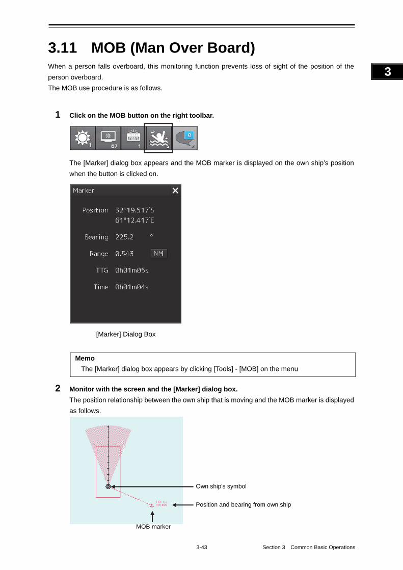
3-43 Section 3 Common Basic Operations
1
2
3
4
5
6
7
8
9
10
11
12
13
14
15
16
17
18
19
20
21
22
23
24
25
APP A
APP B
1
3.11 MOB (Man Over Board) When a person falls overboard, this monitoring function prevents loss of sight of the position of the
person overboard.
The MOB use procedure is as follows.
1 Click on the MOB button on the right toolbar.
The [Marker] dialog box appears and the MOB marker is displayed on the own ship’s position
when the button is clicked on.
Memo
The [Marker] dialog box appears by clicking [Tools] - [MOB] on the menu
2 Monitor with the screen and the [Marker] dialog box.
The position relationship between the own ship that is moving and the MOB marker is displayed
as follows.
MOB marker
Position and bearing from own ship
Own ship's symbol
[Marker] Dialog Box
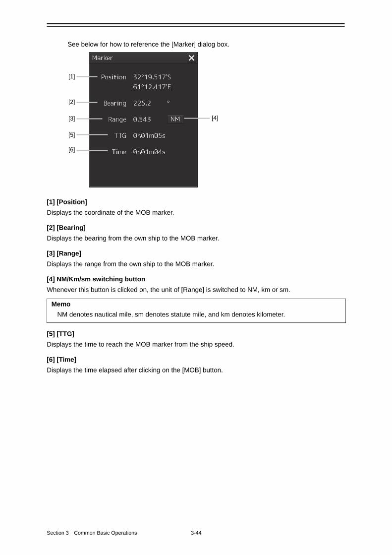
Section 3 Common Basic Operations 3-44
See below for how to reference the [Marker] dialog box.
[1] [Position]
Displays the coordinate of the MOB marker.
[2] [Bearing]
Displays the bearing from the own ship to the MOB marker.
[3] [Range]
Displays the range from the own ship to the MOB marker.
[4] NM/Km/sm switching button
Whenever this button is clicked on, the unit of [Range] is switched to NM, km or sm.
Memo
NM denotes nautical mile, sm denotes statute mile, and km denotes kilometer.
[5] [TTG]
Displays the time to reach the MOB marker from the ship speed.
[6] [Time]
Displays the time elapsed after clicking on the [MOB] button.
[1]
[2]
[3]
[5]
[6]
[4]
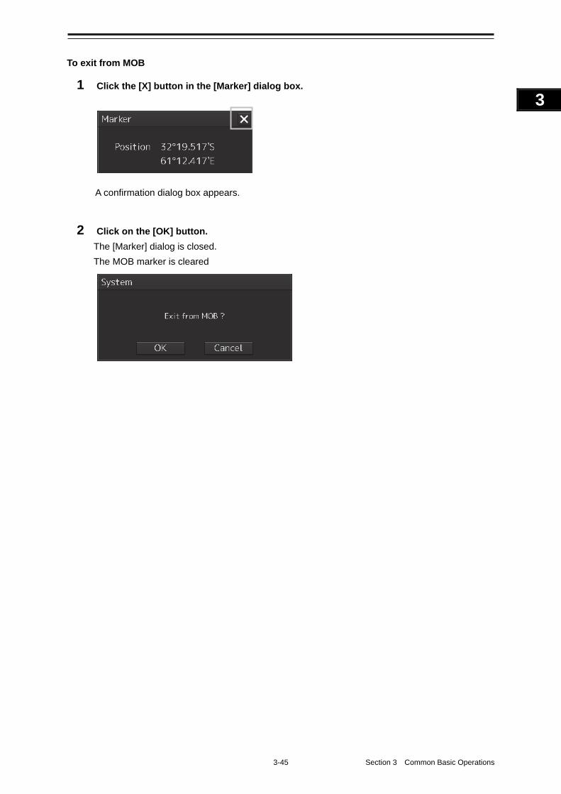
3-45 Section 3 Common Basic Operations
1
2
3
4
5
6
7
8
9
10
11
12
13
14
15
16
17
18
19
20
21
22
23
24
25
APP A
APP B
1
To exit from MOB
1 Click the [X] button in the [Marker] dialog box.
A confirmation dialog box appears.
2 Click on the [OK] button.
The [Marker] dialog is closed.
The MOB marker is cleared
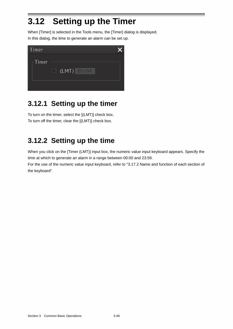
Section 3 Common Basic Operations 3-46
3.12 Setting up the Timer When [Timer] is selected in the Tools menu, the [Timer] dialog is displayed.
In this dialog, the time to generate an alarm can be set up.
3.12.1 Setting up the timer
To turn on the timer, select the [(LMT)] check box.
To turn off the timer, clear the [(LMT)] check box.
3.12.2 Setting up the time
When you click on the [Timer (LMT)] input box, the numeric value input keyboard appears. Specify the
time at which to generate an alarm in a range between 00:00 and 23:59.
For the use of the numeric value input keyboard, refer to "3.17.2 Name and function of each section of
the keyboard".
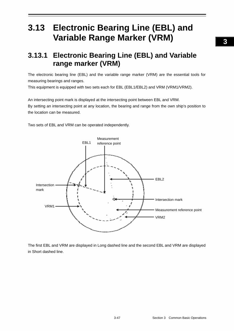
3-47 Section 3 Common Basic Operations
1
2
3
4
5
6
7
8
9
10
11
12
13
14
15
16
17
18
19
20
21
22
23
24
25
APP A
APP B
1
3.13 Electronic Bearing Line (EBL) and Variable Range Marker (VRM)
3.13.1 Electronic Bearing Line (EBL) and Variable range marker (VRM)
The electronic bearing line (EBL) and the variable range marker (VRM) are the essential tools for
measuring bearings and ranges.
This equipment is equipped with two sets each for EBL (EBL1/EBL2) and VRM (VRM1/VRM2).
An intersecting point mark is displayed at the intersecting point between EBL and VRM.
By setting an intersecting point at any location, the bearing and range from the own ship’s position to
the location can be measured.
Two sets of EBL and VRM can be operated independently.
The first EBL and VRM are displayed in Long dashed line and the second EBL and VRM are displayed
in Short dashed line.
Measurement reference point
Measurement reference point
Intersection mark
Intersection mark
EBL1
EBL2
VRM1
VRM2
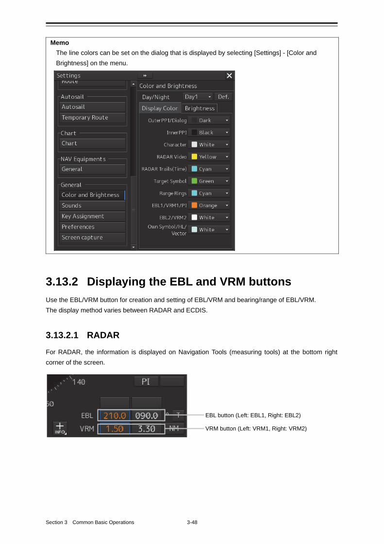
Section 3 Common Basic Operations 3-48
Memo
The line colors can be set on the dialog that is displayed by selecting [Settings] - [Color and
Brightness] on the menu.
3.13.2 Displaying the EBL and VRM buttons
Use the EBL/VRM button for creation and setting of EBL/VRM and bearing/range of EBL/VRM.
The display method varies between RADAR and ECDIS.
3.13.2.1 RADAR
For RADAR, the information is displayed on Navigation Tools (measuring tools) at the bottom right
corner of the screen.
EBL button (Left: EBL1, Right: EBL2)
VRM button (Left: VRM1, Right: VRM2)
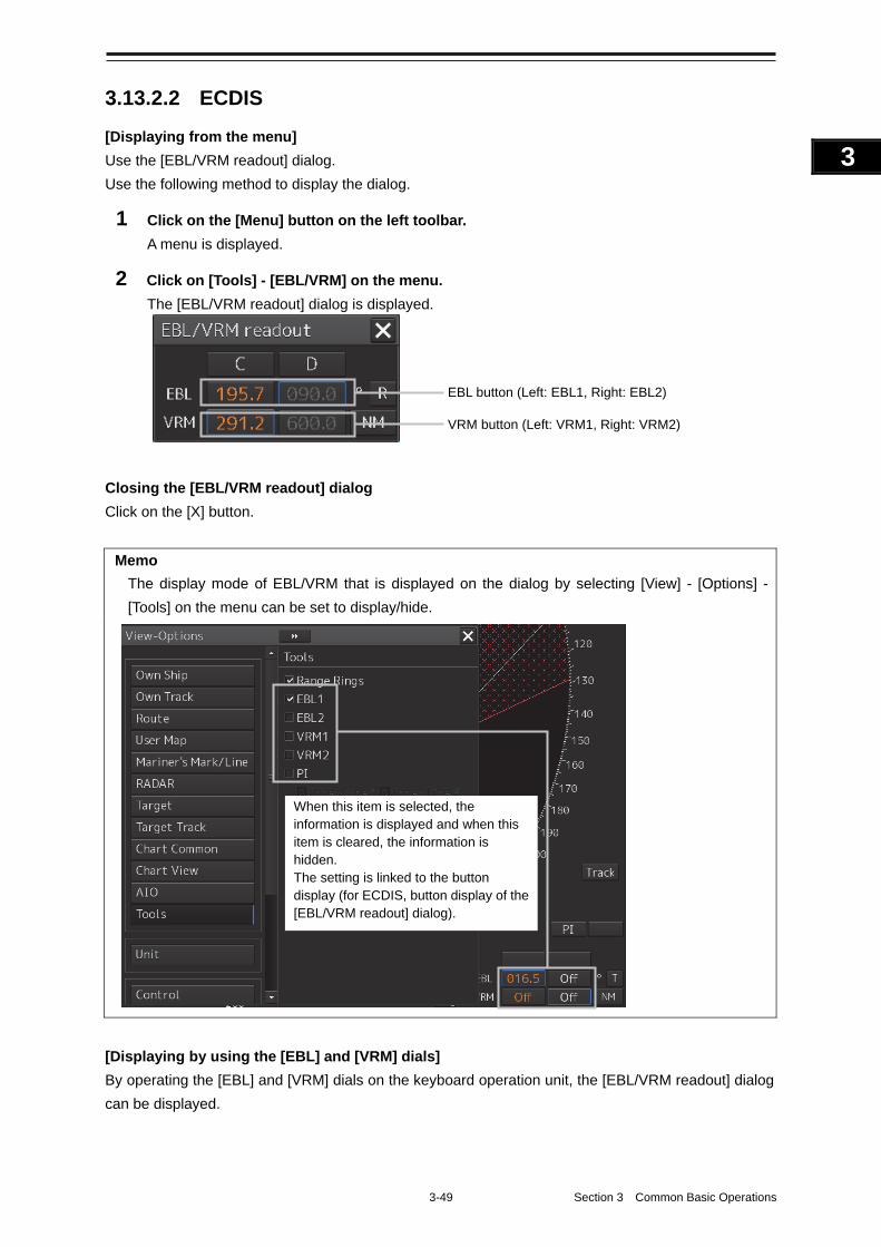
3-49 Section 3 Common Basic Operations
1
2
3
4
5
6
7
8
9
10
11
12
13
14
15
16
17
18
19
20
21
22
23
24
25
APP A
APP B
1
3.13.2.2 ECDIS
[Displaying from the menu]
Use the [EBL/VRM readout] dialog.
Use the following method to display the dialog.
1 Click on the [Menu] button on the left toolbar.
A menu is displayed.
2 Click on [Tools] - [EBL/VRM] on the menu.
The [EBL/VRM readout] dialog is displayed.
Closing the [EBL/VRM readout] dialog
Click on the [X] button.
Memo
The display mode of EBL/VRM that is displayed on the dialog by selecting [View] - [Options] -
[Tools] on the menu can be set to display/hide.
[Displaying by using the [EBL] and [VRM] dials]
By operating the [EBL] and [VRM] dials on the keyboard operation unit, the [EBL/VRM readout] dialog
can be displayed.
EBL button (Left: EBL1, Right: EBL2)
VRM button (Left: VRM1, Right: VRM2)
When this item is selected, the information is displayed and when this item is cleared, the information is hidden. The setting is linked to the button display (for ECDIS, button display of the [EBL/VRM readout] dialog).
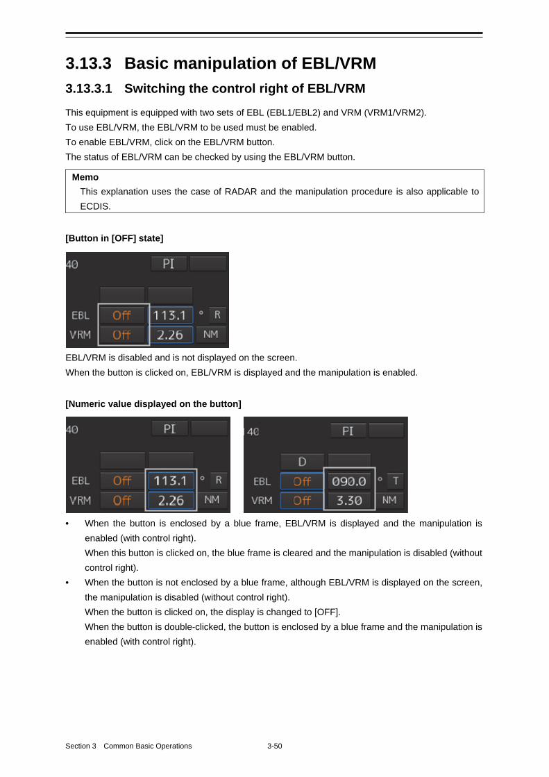
Section 3 Common Basic Operations 3-50
3.13.3 Basic manipulation of EBL/VRM
3.13.3.1 Switching the control right of EBL/VRM
This equipment is equipped with two sets of EBL (EBL1/EBL2) and VRM (VRM1/VRM2).
To use EBL/VRM, the EBL/VRM to be used must be enabled.
To enable EBL/VRM, click on the EBL/VRM button.
The status of EBL/VRM can be checked by using the EBL/VRM button.
Memo
This explanation uses the case of RADAR and the manipulation procedure is also applicable to
ECDIS.
[Button in [OFF] state]
EBL/VRM is disabled and is not displayed on the screen.
When the button is clicked on, EBL/VRM is displayed and the manipulation is enabled.
[Numeric value displayed on the button]
• When the button is enclosed by a blue frame, EBL/VRM is displayed and the manipulation is
enabled (with control right).
When this button is clicked on, the blue frame is cleared and the manipulation is disabled (without
control right).
• When the button is not enclosed by a blue frame, although EBL/VRM is displayed on the screen,
the manipulation is disabled (without control right).
When the button is clicked on, the display is changed to [OFF].
When the button is double-clicked, the button is enclosed by a blue frame and the manipulation is
enabled (with control right).
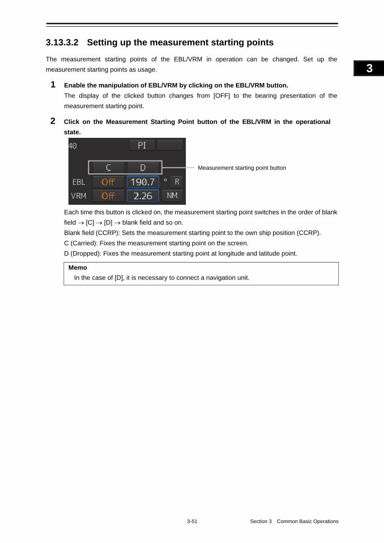
3-51 Section 3 Common Basic Operations
1
2
3
4
5
6
7
8
9
10
11
12
13
14
15
16
17
18
19
20
21
22
23
24
25
APP A
APP B
1
3.13.3.2 Setting up the measurement starting points
The measurement starting points of the EBL/VRM in operation can be changed. Set up the
measurement starting points as usage.
1 Enable the manipulation of EBL/VRM by clicking on the EBL/VRM button.
The display of the clicked button changes from [OFF] to the bearing presentation of the
measurement starting point.
2 Click on the Measurement Starting Point button of the EBL/VRM in the operational
state.
Each time this button is clicked on, the measurement starting point switches in the order of blank
field [C] [D] blank field and so on.
Blank field (CCRP): Sets the measurement starting point to the own ship position (CCRP).
C (Carried): Fixes the measurement starting point on the screen.
D (Dropped): Fixes the measurement starting point at longitude and latitude point.
Memo
In the case of [D], it is necessary to connect a navigation unit.
Measurement starting point button
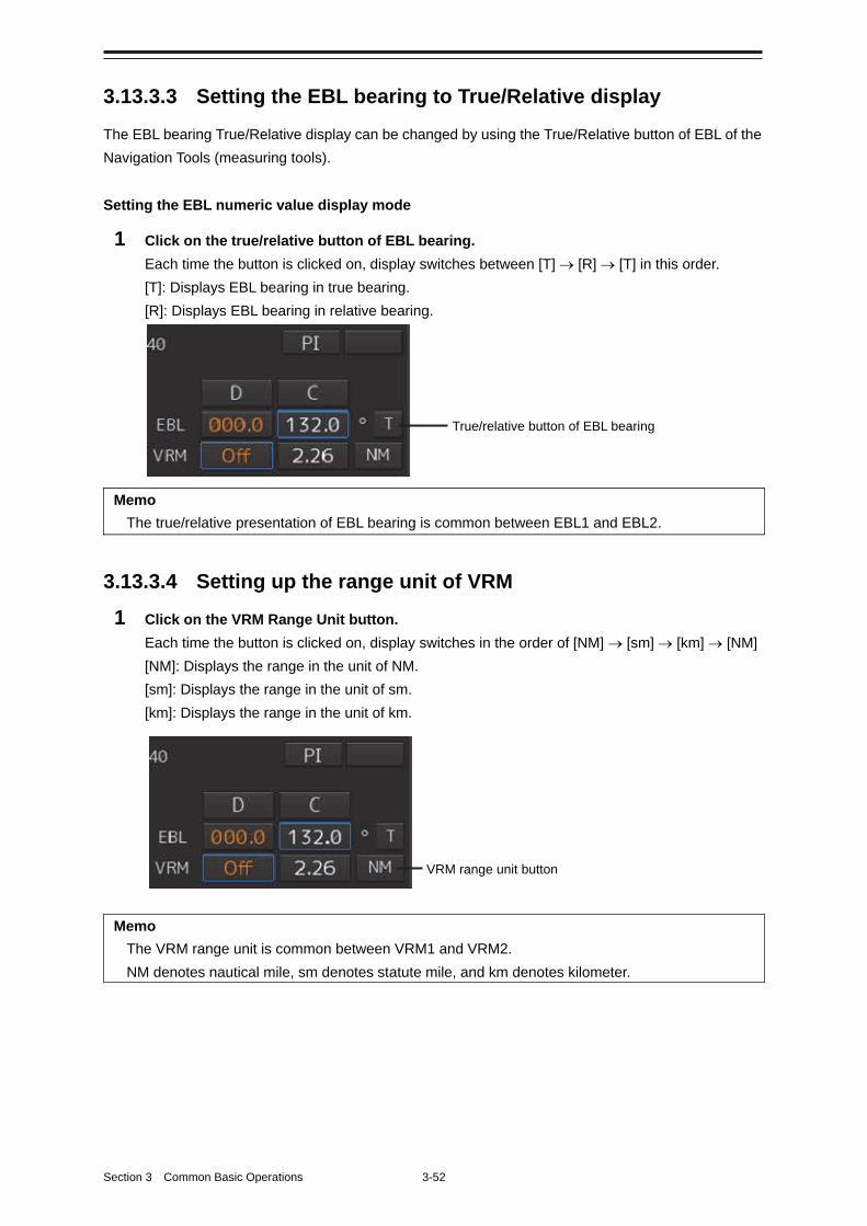
Section 3 Common Basic Operations 3-52
3.13.3.3 Setting the EBL bearing to True/Relative display
The EBL bearing True/Relative display can be changed by using the True/Relative button of EBL of the
Navigation Tools (measuring tools).
Setting the EBL numeric value display mode
1 Click on the true/relative button of EBL bearing.
Each time the button is clicked on, display switches between [T] [R] [T] in this order.
[T]: Displays EBL bearing in true bearing.
[R]: Displays EBL bearing in relative bearing.
Memo
The true/relative presentation of EBL bearing is common between EBL1 and EBL2.
3.13.3.4 Setting up the range unit of VRM
1 Click on the VRM Range Unit button.
Each time the button is clicked on, display switches in the order of [NM] [sm] [km] [NM]
[NM]: Displays the range in the unit of NM.
[sm]: Displays the range in the unit of sm.
[km]: Displays the range in the unit of km.
Memo
The VRM range unit is common between VRM1 and VRM2.
NM denotes nautical mile, sm denotes statute mile, and km denotes kilometer.
VRM range unit button
True/relative button of EBL bearing
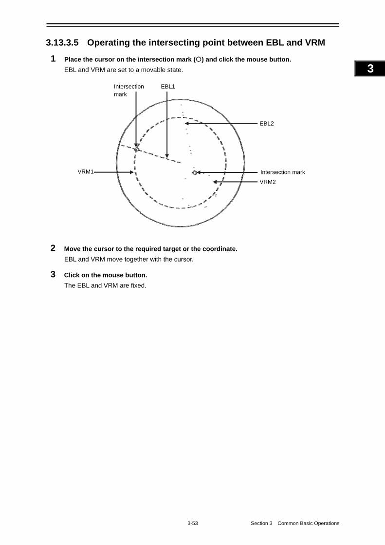
3-53 Section 3 Common Basic Operations
1
2
3
4
5
6
7
8
9
10
11
12
13
14
15
16
17
18
19
20
21
22
23
24
25
APP A
APP B
1
3.13.3.5 Operating the intersecting point between EBL and VRM
1 Place the cursor on the intersection mark () and click the mouse button.
EBL and VRM are set to a movable state.
2 Move the cursor to the required target or the coordinate.
EBL and VRM move together with the cursor.
3 Click on the mouse button.
The EBL and VRM are fixed.
Intersection mark
EBL1
EBL2
VRM2 VRM1
Intersection mark
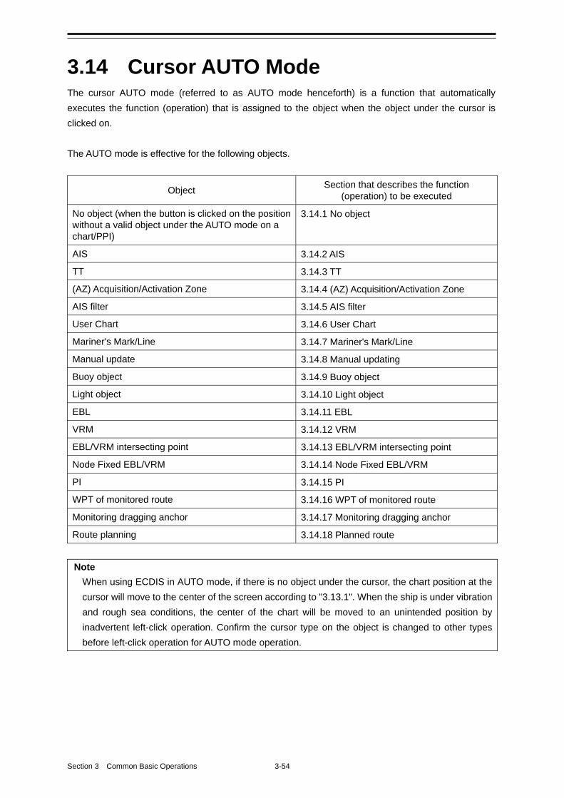
Section 3 Common Basic Operations 3-54
3.14 Cursor AUTO Mode The cursor AUTO mode (referred to as AUTO mode henceforth) is a function that automatically
executes the function (operation) that is assigned to the object when the object under the cursor is
clicked on.
The AUTO mode is effective for the following objects.
Object Section that describes the function
(operation) to be executed
No object (when the button is clicked on the position without a valid object under the AUTO mode on a chart/PPI)
3.14.1 No object
AIS 3.14.2 AIS
TT 3.14.3 TT
(AZ) Acquisition/Activation Zone 3.14.4 (AZ) Acquisition/Activation Zone
AIS filter 3.14.5 AIS filter
User Chart 3.14.6 User Chart
Mariner's Mark/Line 3.14.7 Mariner's Mark/Line
Manual update 3.14.8 Manual updating
Buoy object 3.14.9 Buoy object
Light object 3.14.10 Light object
EBL 3.14.11 EBL
VRM 3.14.12 VRM
EBL/VRM intersecting point 3.14.13 EBL/VRM intersecting point
Node Fixed EBL/VRM 3.14.14 Node Fixed EBL/VRM
PI 3.14.15 PI
WPT of monitored route 3.14.16 WPT of monitored route
Monitoring dragging anchor 3.14.17 Monitoring dragging anchor
Route planning 3.14.18 Planned route
Note
When using ECDIS in AUTO mode, if there is no object under the cursor, the chart position at the
cursor will move to the center of the screen according to "3.13.1". When the ship is under vibration
and rough sea conditions, the center of the chart will be moved to an unintended position by
inadvertent left-click operation. Confirm the cursor type on the object is changed to other types
before left-click operation for AUTO mode operation.
3-55 Section 3 Common Basic Operations
1
2
3
4
5
6
7
8
9
10
11
12
13
14
15
16
17
18
19
20
21
22
23
24
25
APP A
APP B
1
3.14.1 No object
When the button is clicked on the position without a valid object under the AUTO mode on a chart/PPI,
the following operation is performed.
[ECDIS]
Executes off-centering (sets the clicked position as the center of the screen).
[RADAR]
Acquires the TT target manually when the button is clicked on inside of the PPI.
Note
Manual acquisition is not allowed in any of the following cases:
• Radar antenna standby state
• Occurrence of PROC (Interrupt 1) / PROC (Interrupt 2) alert
• Occurrence of target tracking function alert.
• Occurrence of ship's heading alert.
• Using at the position further than 32 NM from the own ship’s position
• Using at the position closer than 0.1 NM from the own ship’s position
3.14.2 AIS
[Sleeping AIS target target]
When a sleeping AIS target is clicked on, the AIS target is activated.
[Activated AIS target]
When an Activated AIS target is clicked on, the AIS target value is displayed.
[Numeric displayed AIS target]
When the numeric displayed AIS target is clicked on, the AIS target value display is cancelled.
[AIS-SAR aircraft normal target]
When an AIS-SAR aircraft in the normal state is clicked on, the AIS-SAR aircraft is selected and the
AIS-SAR aircraft value is displayed.
[Numeric displayed AIS-SAR aircraft]
When a numeric displayed AIS-SAR aircraft is clicked on, the sleeping target of the AIS-SAR aircraft is
displayed and the AIS-SAR aircraft value display is cancelled.
[Sleeping AIS-SAR vessel target]
The same operation as the normal sleeping AIS target is performed.
Section 3 Common Basic Operations 3-56
[Activated AIS-SAR vessel target]
The same operation as the normal activated AIS target is performed.
[Numeric displayed AIS-SAR vessel target]
The same operation as the normal numeric displayed AIS target is performed.
[Sleeping AIS-SART]
The same operation as the normal sleeping AIS target is performed.
[Activated AIS-SART]
The same operation as the normal activated AIS target is performed.
[Numeric displayed AIS-SART target]
The same operation as the normal numeric displayed AIS target is performed.
[AtoN normal target]
When AtoN target in a normal state is clicked on, the AtoN normal target is selected and the numeric
value of AtoN is displayed.
[Numeric displayed AtoN target]
When a numeric displayed AtoN target is clicked on, the AtoN normal target is deselected and the
numeric value of AtoN normal target is cancelled.
[AIS-shore base station normal target]
When an AIS-shore base station target in a normal state is clicked on, the AIS-shore base station is
selected and the numeric value of AIS-shore base station is displayed.
[Numeric displayed AIS-shore base station normal target]
When an AIS-shore base station in a normal state is clicked on, the AIS-shore base station is
deselected and the numeric value of AIS-shore base station is cancelled.
3.14.3 TT
[TT target]
When TT target is clicked on, a numeric value is displayed.
[Numeric displayed TT target]
When a numeric displayed TT target is clicked on, the numeric value display of TT is cancelled.
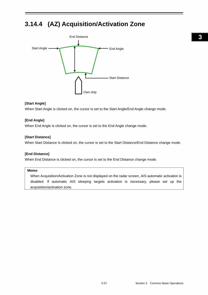
3-57 Section 3 Common Basic Operations
1
2
3
4
5
6
7
8
9
10
11
12
13
14
15
16
17
18
19
20
21
22
23
24
25
APP A
APP B
1
3.14.4 (AZ) Acquisition/Activation Zone
[Start Angle]
When Start Angle is clicked on, the cursor is set to the Start Angle/End Angle change mode.
[End Angle]
When End Angle is clicked on, the cursor is set to the End Angle change mode.
[Start Distance]
When Start Distance is clicked on, the cursor is set to the Start Distance/End Distance change mode.
[End Distance]
When End Distance is clicked on, the cursor is set to the End Distance change mode.
Memo
When Acquisition/Activation Zone is not displayed on the radar screen, AIS automatic activation is
disabled. If automatic AIS sleeping targets activation is necessary, please set up the
acquisition/activation zone.
End Distance
Start Angle End Angle
Own ship
Start Distance
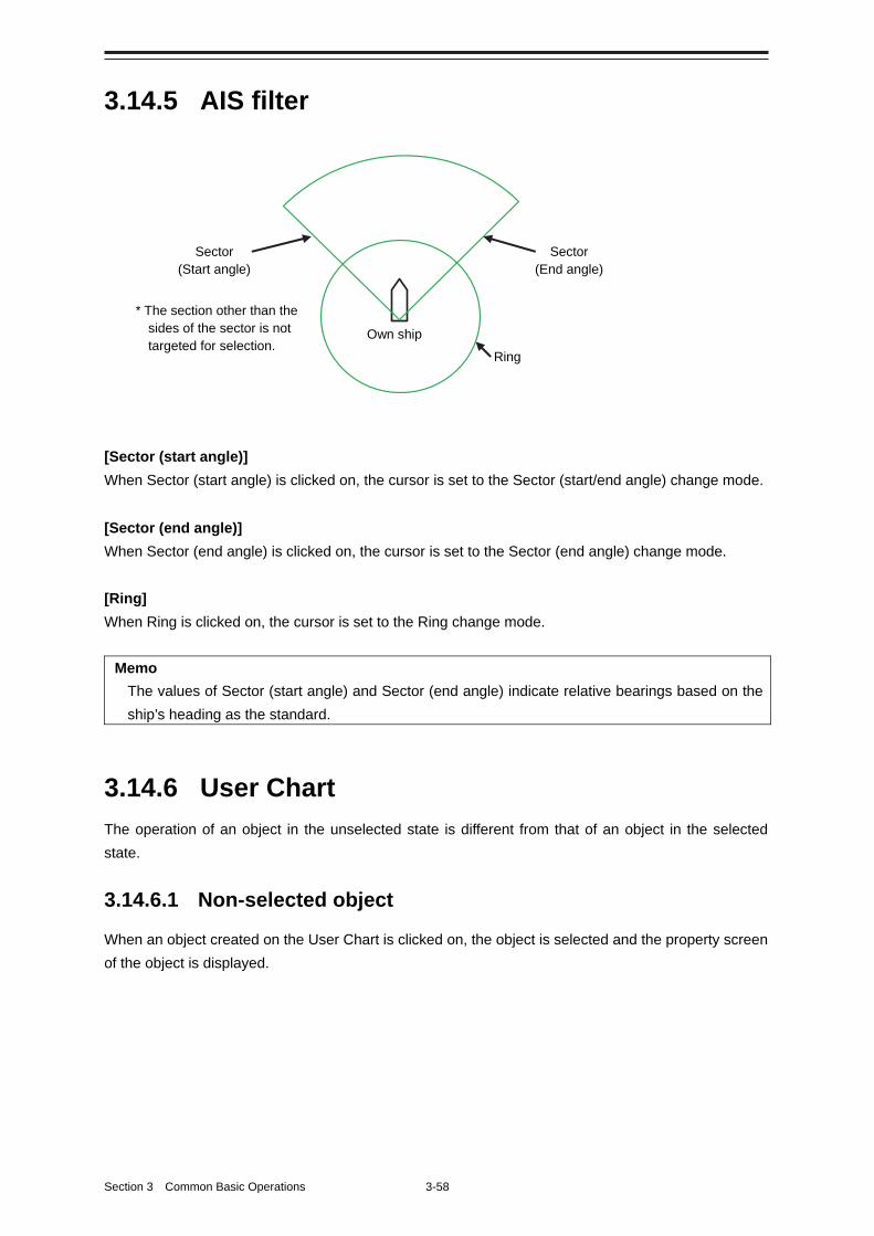
Section 3 Common Basic Operations 3-58
3.14.5 AIS filter
[Sector (start angle)]
When Sector (start angle) is clicked on, the cursor is set to the Sector (start/end angle) change mode.
[Sector (end angle)]
When Sector (end angle) is clicked on, the cursor is set to the Sector (end angle) change mode.
[Ring]
When Ring is clicked on, the cursor is set to the Ring change mode.
Memo
The values of Sector (start angle) and Sector (end angle) indicate relative bearings based on the
ship’s heading as the standard.
3.14.6 User Chart
The operation of an object in the unselected state is different from that of an object in the selected
state.
3.14.6.1 Non-selected object
When an object created on the User Chart is clicked on, the object is selected and the property screen
of the object is displayed.
Sector (Start angle)
Ring
Own ship
Sector (End angle)
* The section other than the sides of the sector is not targeted for selection.
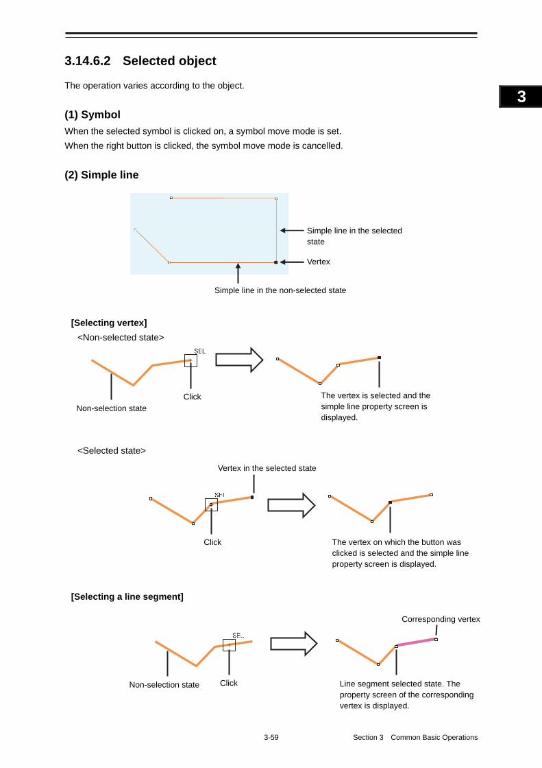
3-59 Section 3 Common Basic Operations
1
2
3
4
5
6
7
8
9
10
11
12
13
14
15
16
17
18
19
20
21
22
23
24
25
APP A
APP B
1
3.14.6.2 Selected object
The operation varies according to the object.
(1) Symbol
When the selected symbol is clicked on, a symbol move mode is set.
When the right button is clicked, the symbol move mode is cancelled.
(2) Simple line
[Selecting vertex]
<Non-selected state>
<Selected state>
[Selecting a line segment]
Click Non-selection state
Corresponding vertex
Line segment selected state. The property screen of the corresponding vertex is displayed.
Click The vertex on which the button was clicked is selected and the simple line property screen is displayed.
Vertex in the selected state
Non-selection state Click The vertex is selected and the
simple line property screen is displayed.
Simple line in the non-selected state
Vertex
Simple line in the selected state
Section 3 Common Basic Operations 3-60
[Moving a vertex]
When the middle point of simple line in the selected state is clicked on, vertex move mode of simple
line is set.
[Inserting a vertex]
When a line segment of simple line in the selected state is clicked on, vertex insertion mode of simple
line is set.
Memo
A vertex can also be inserted by using [Insert Vertex] on the context menu that is displayed by
clicking the right button on the simple line in the selected state.
When the insertion point is the starting point or the ending point, a vertex can be inserted with [Add
Vertex].
[Cancelling operation]
By clicking the right button, the vertex addition, move, or insertion mode can be cancelled.
(3) Line-Circle
[Moving Line-Circle]
When the circumference of the line-circle in the selected state is clicked on, move mode of line-circle
is set.
[Chainging a radius]
When a square of four corners of the line-circle in the selected state is clicked on, radius set mode of
line-circle is set.
[Cancelling operation]
By clicking the right button, the line-circle move or radius change mode can be cancelled.
(4) Line-Ellipse
[Moving line-ellipse]
When the circumference of the line-ellipse in the selected state is clicked on, move mode of
line-ellipse is set.
[Changing vertical/horizontal width]
When a square of four corners of the line-ellipse in the selected state is clicked on, a
vertical/horizontal width change of line-ellipse mode is set.
[Cancelling operation]
By clicking the right button, the line-ellipse move or vertical/horizontal width change mode can be
cancelled.
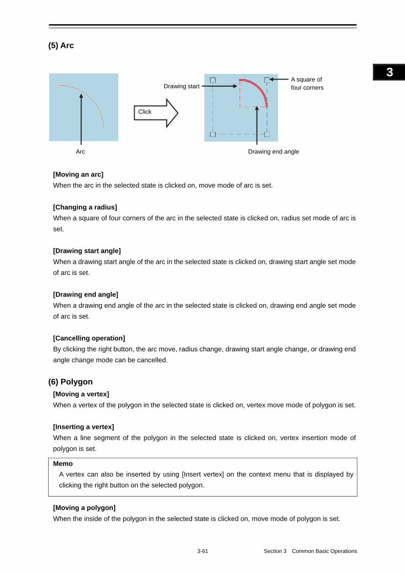
3-61 Section 3 Common Basic Operations
1
2
3
4
5
6
7
8
9
10
11
12
13
14
15
16
17
18
19
20
21
22
23
24
25
APP A
APP B
1
(5) Arc
[Moving an arc]
When the arc in the selected state is clicked on, move mode of arc is set.
[Changing a radius]
When a square of four corners of the arc in the selected state is clicked on, radius set mode of arc is
set.
[Drawing start angle]
When a drawing start angle of the arc in the selected state is clicked on, drawing start angle set mode
of arc is set.
[Drawing end angle]
When a drawing end angle of the arc in the selected state is clicked on, drawing end angle set mode
of arc is set.
[Cancelling operation]
By clicking the right button, the arc move, radius change, drawing start angle change, or drawing end
angle change mode can be cancelled.
(6) Polygon
[Moving a vertex]
When a vertex of the polygon in the selected state is clicked on, vertex move mode of polygon is set.
[Inserting a vertex]
When a line segment of the polygon in the selected state is clicked on, vertex insertion mode of
polygon is set.
Memo
A vertex can also be inserted by using [Insert vertex] on the context menu that is displayed by
clicking the right button on the selected polygon.
[Moving a polygon]
When the inside of the polygon in the selected state is clicked on, move mode of polygon is set.
A square of four corners Drawing start
Drawing end angle Arc
Click

Section 3 Common Basic Operations 3-62
[Cancelling operation]
By clicking the right button, the vertex move, insertion, or polygon move mode can be cancelled.
(7) Area-Circle
[Moving Area-Circle]
When the circumference of the area-circle in the selected state is clicked on, an area-circle move
mode is set.
[Changing a radius]
When a square formed by four corners of area-circle in the selected state is clicked on, an area-circle
radius setting mode is set.
[Cancelling operation]
By clicking the right button, the area-circle move or radius change mode can be cancelled.
(8) Area-Ellipse
[Moving area-ellipse]
When the circumference or inside of the area-ellipse in the selected state is clicked on, an
area-ellipse move mode is set.
[Changing a radius]
When a square formed by four corners of area-ellipse in the selected state is clicked on, an
area-ellipse radius setting mode is set.
[Cancelling operation]
By clicking the right button, the area-ellipse move or radius change mode can be cancelled.
(9) Sector
[Moving a sector]
When a circumference or inside of the sector in the selected state is clicked on, a fan move mode is
set.
[Changing a radius]
When a square formed by four corners of the sector in the selected state is clicked on, a sector radius
setting mode is set.
[Drawing start angle]
When a drawing start angle of the sector in the selected state is clicked on, a sector drawing start
angle setting mode is set.
[Drawing end angle]
When a sector drawing end angle in the selected state is clicked on, a sector drawing end angle
setting mode is set.
3-63 Section 3 Common Basic Operations
1
2
3
4
5
6
7
8
9
10
11
12
13
14
15
16
17
18
19
20
21
22
23
24
25
APP A
APP B
1
[Cancelling operation]
By clicking on the right button, the sector move, radius change, drawing start angle change or
drawing end angle change mode can be cancelled.
(10) Text
[Moving text]
When the text object in the selected state is clicked on, move mode of the text object is set.
[Cancelling operation]
By clicking the right button, the text move mode can be cancelled.
(11) Arrow
[Moving an arrow]
When a line segment of the arrow in the selected state is clicked on, move mode of the arrow is set.
[Moving a start point]
When a start point of the arrow in the selected state is clicked on, start point move mode of the arrow
is set.
[Moving an end point]
When an end point of the arrow in the selected state is clicked on, end point move mode of the arrow
is set.
[Cancelling operation]
By clicking the right button, the arrow move or start point/end point move mode can be cancelled.
3.14.7 Mariner's Mark/Line
3.14.7.1 Object in the non-selected state
When the object that is created by using Mariner's Mark/Line is clicked on, the object is selected and
the property screen of the object is displayed.
3.14.7.2 Object in selected state
The operation varies according to the object.
(1) Event mark in the selected state
When an event mark is clicked on, the selected state of the event mark is cleared.
(2) Information Mark
When Information Mark in the selected state is clicked on, move mode of Information Mark is set.
By clicking the right button, the Information Mark move mode can be cancelled.
i
Section 3 Common Basic Operations 3-64
(3) Tidal Stream
When Tidal Stream in the selected state is clicked on, move mode of Tidal Stream is set.
By clicking the right button, the Tidal Stream move mode can be cancelled.
(4) Clearing Line
[Moving Clearing Line]
When a line segment of Clearing Line in the selected state is clicked on, move mode of Clearing Line
is set.
[Moving a start point]
When a start point of Clearing Line in the selected state is clicked on, start point move mode of
Clearing Line is set.
[Moving an end point]
When an end point of Clearing Line in the selected state is clicked on, end point move mode of
Clearing Line is set.
[Cancelling operation]
By clicking the right button, the Clearing Line move or start point/end point move mode can be
cancelled.
(5) Highlight
[Moving a vertex]
When a vertex of a highlight in the selected state is clicked on, vertex move mode of highlight is set.
[Inserting a vertex]
When a line segment of a highlight in the selected state is clicked on, vertex insertion mode of
highlight is set.
Memo
A vertex can also be inserted by using [Insert vertex] on the context menu that is displayed by
clicking the right button on a highlight in the selected state.
[Moving a highlight]
When an inside of a highlight in the selected state is clicked on, entire shift mode of highlight is set.
[Cancelling operation]
By clicking the right button, the vertex move, insertion, or highlight move mode can be cancelled.
(6) Plotted Position
[Moving a Plotted position]
When Plotted position in the selected state is clicked on, a Plotted position mode move is set.
[Cancelling operation]
By clicking the right button, the Plotted position move mode can be cancelled.
3-65 Section 3 Common Basic Operations
1
2
3
4
5
6
7
8
9
10
11
12
13
14
15
16
17
18
19
20
21
22
23
24
25
APP A
APP B
1
3.14.8 Manual updating
3.14.8.1 Unsaved object
The operation of AUTO mode of unsaved objects is the same as for the User Chart.
3.14.8.2 Saved object
When setting an edit mode by clicking on the saved object, the property screen of the saved object is
displayed.
3.14.8.3 C-MAP chart
When the C-MAP chart is updated manually and any of the following conditions is satisfied, the
updated object is deleted automatically.
• The database has been updated.
3.14.9 Buoy object
When a buoy object is clicked on, a pick cursor is displayed at the clicked point and the [Chart Info] tab
of the [Pick Report] dialog box is displayed.
Memo
The pick cursor indicates a square frame that is displayed at the point from which the chart
information was read and the chart object information inside of the frame is displayed in the [Pick
Report] dialog.
3.14.10 Light object
When a light object is clicked on, a pick cursor is displayed at the selected point and the [Chart Info] tab
of the [Pick Report] dialog box is displayed.
Memo
The pick cursor indicates a square frame that is displayed at the point from which the chart
information was read and the chart object information inside of the frame is displayed in the [Pick
Report] dialog.
3.14.11 EBL
When EBL is clicked, the mode becomes one in which EBL is operated alone.
Section 3 Common Basic Operations 3-66
3.14.12 VRM
When VRM is clicked, the mode becomes one in which VRM is operated alone.
3.14.13 EBL/VRM intersecting point
When the EBL/VRM intersection point is clicked, the mode becomes one in which EBL and VRM are
operated simultaneously.
3.14.14 Node Fixed EBL/VRM
When Node Fixed EBL/VRM is clicked on, the clicked point becomes the EBL/VRM intersecting point,
and an EBL/VRM (1step) drawing mode is set. (The start point follows the own ship’s position.)
3.14.15 PI
Four PI setting modes are available and the operation of the cursor AUTO mode varies depending
on the setting.
For the details, refer to "4.6 Using Parallel Index Line (PI)".
3.14.16 WPT of monitored route
When a WPT of a monitored route is clicked on, the detail information of the WPT is displayed.
3.14.17 Monitoring dragging anchor
3.14.17.1 Object in the unselected state
When a monitoring dragging anchor object is clicked on, the clicked object is set to the selected state
and the [Anchor Watch] dialog box is displayed.
3.14.17.2 Selected state
Dragging anchor monitoring circle
[Changing a radius]
When a square of the four corners of a dragging anchor monitoring circle in the selected state is
clicked on, radius setting mode of dragging anchor monitoring circle is set.
[Cancelling operation]
By clicking the right button, the dragging anchor monitoring circle move or radius change mode can
be cancelled.
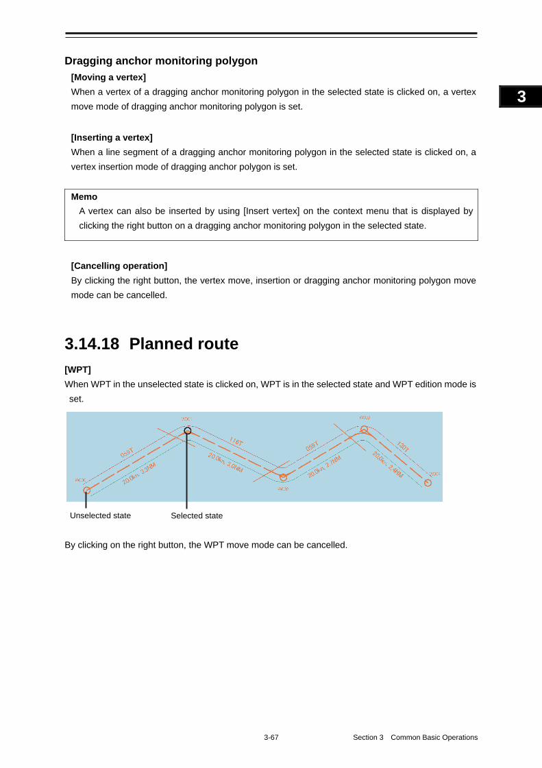
3-67 Section 3 Common Basic Operations
1
2
3
4
5
6
7
8
9
10
11
12
13
14
15
16
17
18
19
20
21
22
23
24
25
APP A
APP B
1
Dragging anchor monitoring polygon
[Moving a vertex]
When a vertex of a dragging anchor monitoring polygon in the selected state is clicked on, a vertex
move mode of dragging anchor monitoring polygon is set.
[Inserting a vertex]
When a line segment of a dragging anchor monitoring polygon in the selected state is clicked on, a
vertex insertion mode of dragging anchor polygon is set.
Memo
A vertex can also be inserted by using [Insert vertex] on the context menu that is displayed by
clicking the right button on a dragging anchor monitoring polygon in the selected state.
[Cancelling operation]
By clicking the right button, the vertex move, insertion or dragging anchor monitoring polygon move
mode can be cancelled.
3.14.18 Planned route
[WPT]
When WPT in the unselected state is clicked on, WPT is in the selected state and WPT edition mode is
set.
By clicking on the right button, the WPT move mode can be cancelled.
Unselected state Selected state
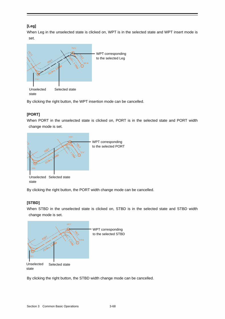
Section 3 Common Basic Operations 3-68
[Leg]
When Leg in the unselected state is clicked on, WPT is in the selected state and WPT insert mode is
set.
By clicking the right button, the WPT insertion mode can be cancelled.
[PORT]
When PORT in the unselected state is clicked on, PORT is in the selected state and PORT width
change mode is set.
By clicking the right button, the PORT width change mode can be cancelled.
[STBD]
When STBD in the unselected state is clicked on, STBD is in the selected state and STBD width
change mode is set.
By clicking the right button, the STBD width change mode can be cancelled.
Unselected state
WPT corresponding to the selected STBD
Selected state
Unselected state
WPT corresponding to the selected PORT
Selected state
Unselected state
Selected state
WPT corresponding to the selected Leg
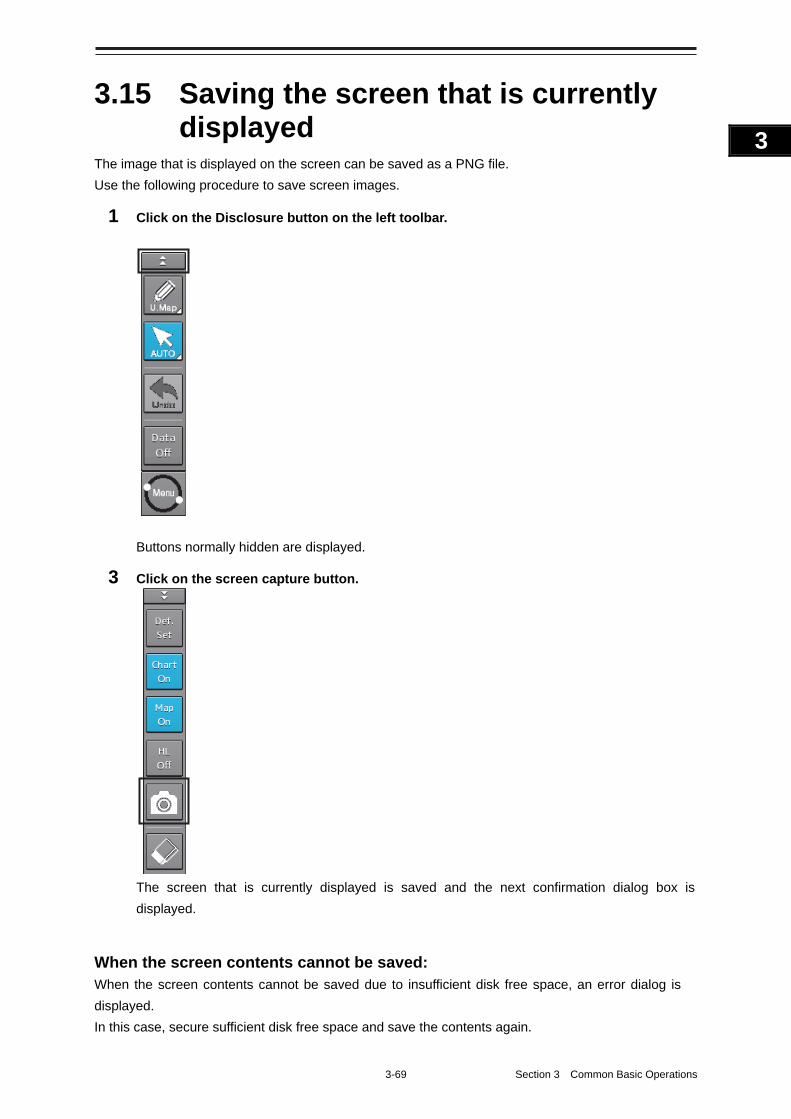
3-69 Section 3 Common Basic Operations
1
2
3
4
5
6
7
8
9
10
11
12
13
14
15
16
17
18
19
20
21
22
23
24
25
APP A
APP B
1
3.15 Saving the screen that is currently displayed
The image that is displayed on the screen can be saved as a PNG file.
Use the following procedure to save screen images.
1 Click on the Disclosure button on the left toolbar.
Buttons normally hidden are displayed.
3 Click on the screen capture button.
The screen that is currently displayed is saved and the next confirmation dialog box is
displayed.
When the screen contents cannot be saved: When the screen contents cannot be saved due to insufficient disk free space, an error dialog is
displayed.
In this case, secure sufficient disk free space and save the contents again.
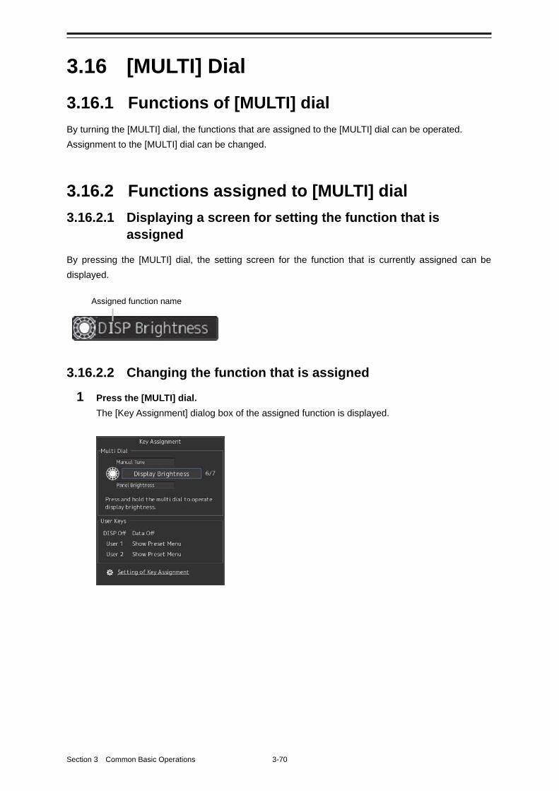
Section 3 Common Basic Operations 3-70
3.16 [MULTI] Dial
3.16.1 Functions of [MULTI] dial
By turning the [MULTI] dial, the functions that are assigned to the [MULTI] dial can be operated.
Assignment to the [MULTI] dial can be changed.
3.16.2 Functions assigned to [MULTI] dial
3.16.2.1 Displaying a screen for setting the function that is assigned
By pressing the [MULTI] dial, the setting screen for the function that is currently assigned can be
displayed.
3.16.2.2 Changing the function that is assigned
1 Press the [MULTI] dial.
The [Key Assignment] dialog box of the assigned function is displayed.
Assigned function name
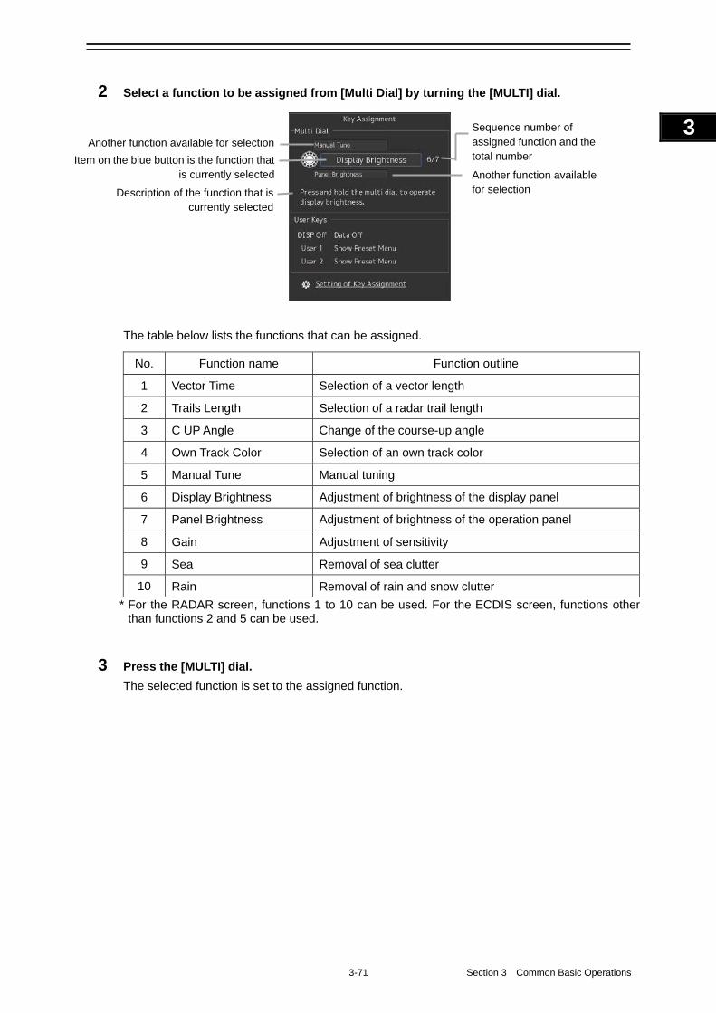
3-71 Section 3 Common Basic Operations
1
2
3
4
5
6
7
8
9
10
11
12
13
14
15
16
17
18
19
20
21
22
23
24
25
APP A
APP B
1
2 Select a function to be assigned from [Multi Dial] by turning the [MULTI] dial.
The table below lists the functions that can be assigned.
No. Function name Function outline
1 Vector Time Selection of a vector length
2 Trails Length Selection of a radar trail length
3 C UP Angle Change of the course-up angle
4 Own Track Color Selection of an own track color
5 Manual Tune Manual tuning
6 Display Brightness Adjustment of brightness of the display panel
7 Panel Brightness Adjustment of brightness of the operation panel
8 Gain Adjustment of sensitivity
9 Sea Removal of sea clutter
10 Rain Removal of rain and snow clutter
* For the RADAR screen, functions 1 to 10 can be used. For the ECDIS screen, functions other than functions 2 and 5 can be used.
3 Press the [MULTI] dial.
The selected function is set to the assigned function.
Sequence number of assigned function and the total number
Another function available for selection
Another function available for selection
Item on the blue button is the function that is currently selected
Description of the function that is currently selected
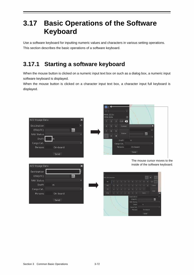
Section 3 Common Basic Operations 3-72
3.17 Basic Operations of the Software Keyboard
Use a software keyboard for inputting numeric values and characters in various setting operations.
This section describes the basic operations of a software keyboard.
3.17.1 Starting a software keyboard
When the mouse button is clicked on a numeric input text box on such as a dialog box, a numeric input
software keyboard is displayed.
When the mouse button is clicked on a character input text box, a character input full keyboard is
displayed.
The mouse cursor moves to the inside of the software keyboard.
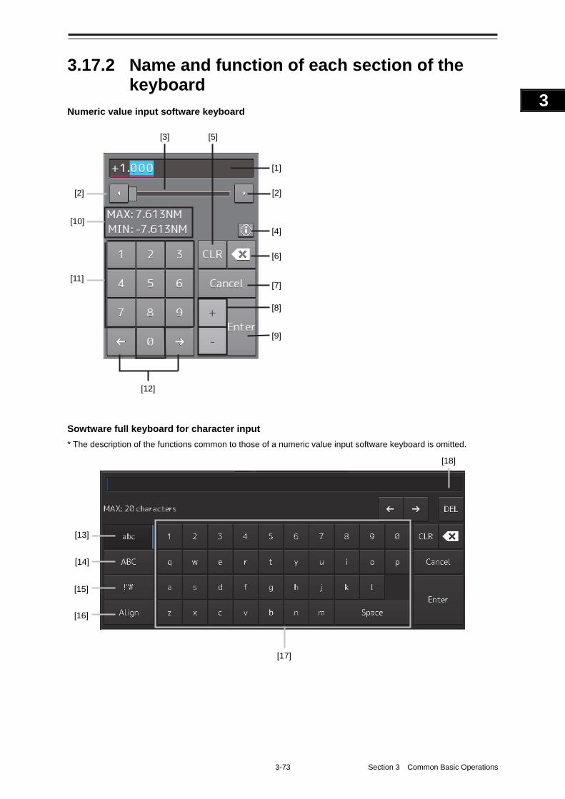
3-73 Section 3 Common Basic Operations
1
2
3
4
5
6
7
8
9
10
11
12
13
14
15
16
17
18
19
20
21
22
23
24
25
APP A
APP B
1
3.17.2 Name and function of each section of the keyboard
Numeric value input software keyboard
Sowtware full keyboard for character input
* The description of the functions common to those of a numeric value input software keyboard is omitted.
[18]
[17]
[13]
[14]
[15]
[16]
[1]
[2] [2]
[3]
[4]
[5]
[7]
[8]
[9]
[12]
[6]
[10]
[11]
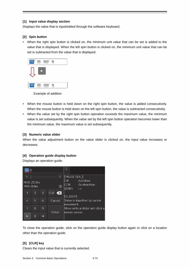
Section 3 Common Basic Operations 3-74
[1] Input value display section
Displays the value that is input/edited through the software keyboard.
[2] Spin button
• When the right spin button is clicked on, the minimum unit value that can be set is added to the
value that is displayed. When the left spin button is clicked on, the minimum unit value that can be
set is subtracted from the value that is displayed.
Example of addition
• When the mouse button is held down on the right spin button, the value is added consecutively.
When the mouse button is held down on the left spin button, the value is subtracted consecutively.
• When the value set by the right spin button operation exceeds the maximum value, the minimum
value is set subsequently. When the value set by the left spin button operation becomes lower than
the minimum value, the maximum value is set subsequently.
[3] Numeric value slider
When the value adjustment button on the value slider is clicked on, the input value increases or
decreases.
[4] Operation guide display button
Displays an operation guide.
To close the operation guide, click on the operation guide display button again or click on a location
other than the operation guide.
[5] [CLR] key
Clears the input value that is currently selected.
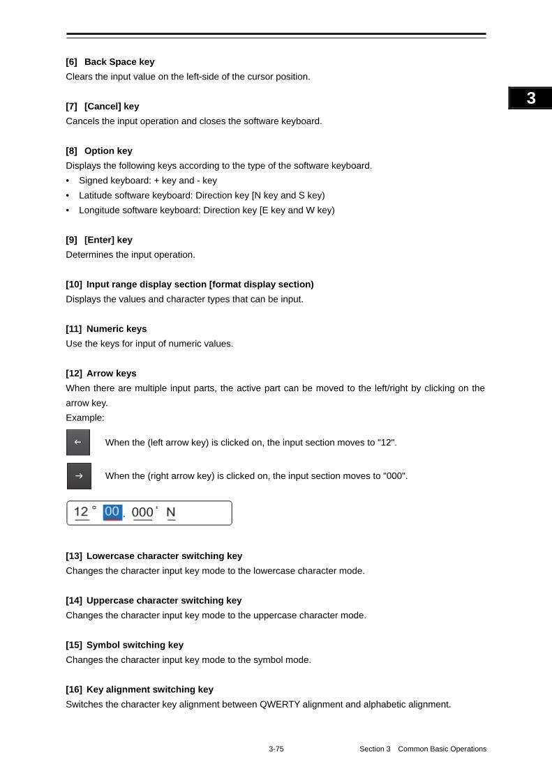
3-75 Section 3 Common Basic Operations
1
2
3
4
5
6
7
8
9
10
11
12
13
14
15
16
17
18
19
20
21
22
23
24
25
APP A
APP B
1
[6] Back Space key
Clears the input value on the left-side of the cursor position.
[7] [Cancel] key
Cancels the input operation and closes the software keyboard.
[8] Option key
Displays the following keys according to the type of the software keyboard.
• Signed keyboard: + key and - key
• Latitude software keyboard: Direction key [N key and S key)
• Longitude software keyboard: Direction key [E key and W key)
[9] [Enter] key
Determines the input operation.
[10] Input range display section [format display section)
Displays the values and character types that can be input.
[11] Numeric keys
Use the keys for input of numeric values.
[12] Arrow keys
When there are multiple input parts, the active part can be moved to the left/right by clicking on the
arrow key.
Example:
When the (left arrow key) is clicked on, the input section moves to "12".
When the (right arrow key) is clicked on, the input section moves to "000".
[13] Lowercase character switching key
Changes the character input key mode to the lowercase character mode.
[14] Uppercase character switching key
Changes the character input key mode to the uppercase character mode.
[15] Symbol switching key
Changes the character input key mode to the symbol mode.
[16] Key alignment switching key
Switches the character key alignment between QWERTY alignment and alphabetic alignment.
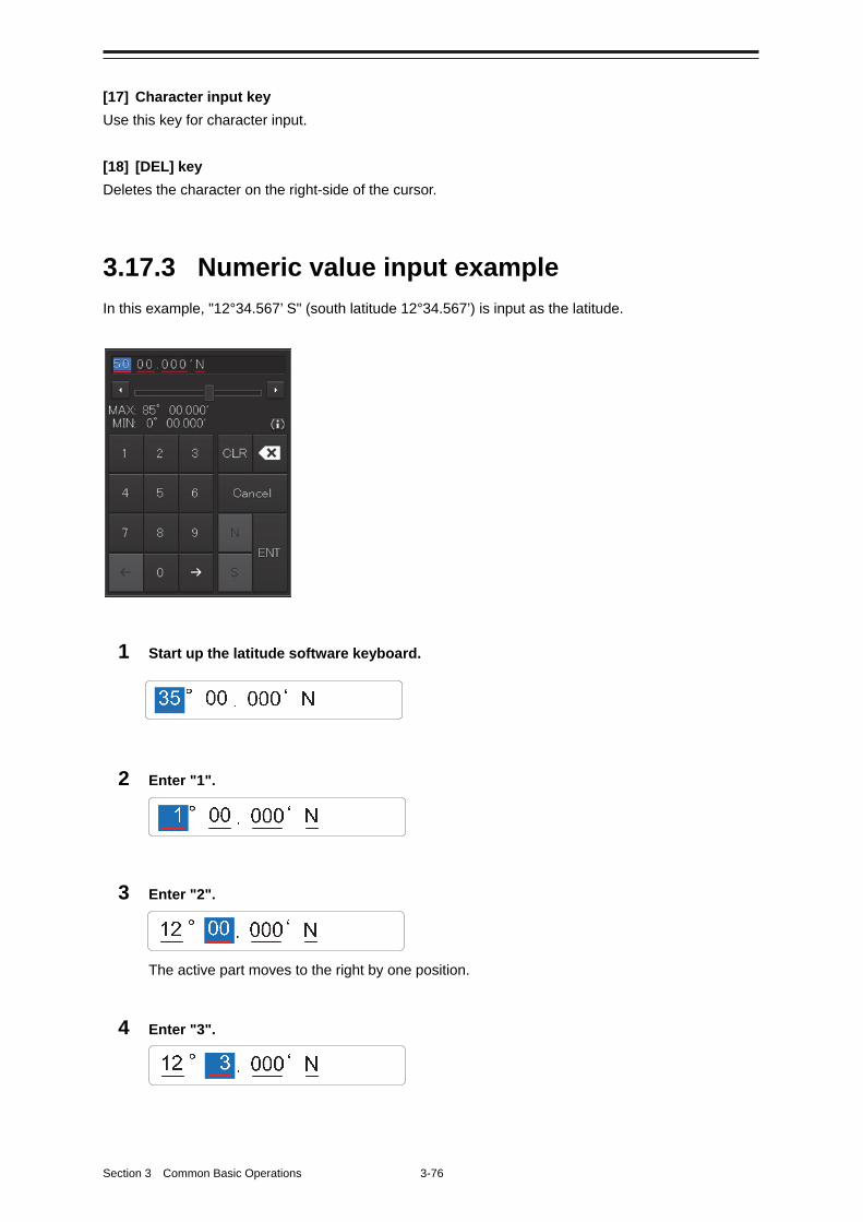
Section 3 Common Basic Operations 3-76
[17] Character input key
Use this key for character input.
[18] [DEL] key
Deletes the character on the right-side of the cursor.
3.17.3 Numeric value input example
In this example, "12°34.567’ S" (south latitude 12°34.567’) is input as the latitude.
1 Start up the latitude software keyboard.
2 Enter "1".
3 Enter "2".
The active part moves to the right by one position.
4 Enter "3".
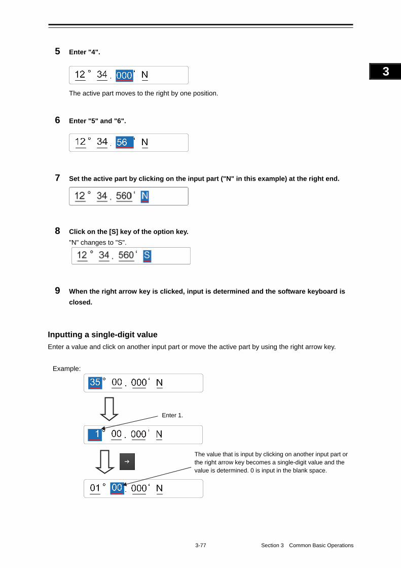
3-77 Section 3 Common Basic Operations
1
2
3
4
5
6
7
8
9
10
11
12
13
14
15
16
17
18
19
20
21
22
23
24
25
APP A
APP B
1
5 Enter "4".
The active part moves to the right by one position.
6 Enter "5" and "6".
7 Set the active part by clicking on the input part ("N" in this example) at the right end.
8 Click on the [S] key of the option key.
"N" changes to "S".
9 When the right arrow key is clicked, input is determined and the software keyboard is
closed.
Inputting a single-digit value
Enter a value and click on another input part or move the active part by using the right arrow key.
Example:
Enter 1.
The value that is input by clicking on another input part or the right arrow key becomes a single-digit value and the value is determined. 0 is input in the blank space.
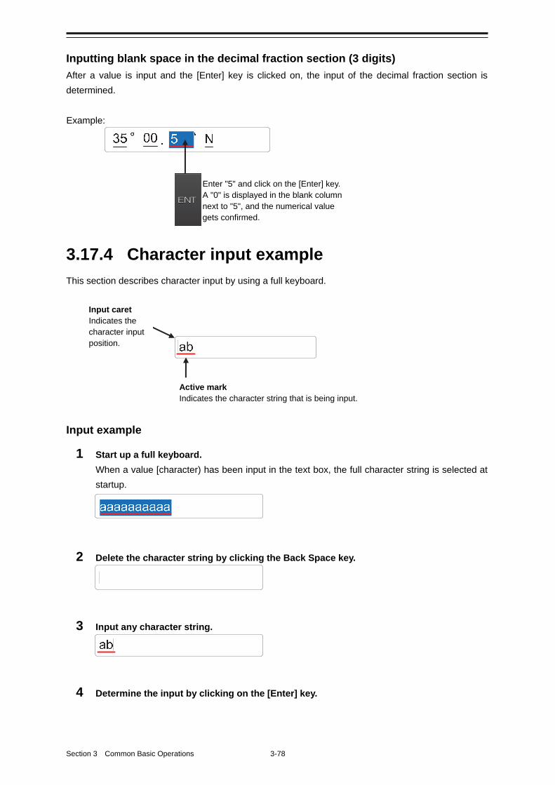
Section 3 Common Basic Operations 3-78
Inputting blank space in the decimal fraction section (3 digits)
After a value is input and the [Enter] key is clicked on, the input of the decimal fraction section is
determined.
3.17.4 Character input example
This section describes character input by using a full keyboard.
Input example
1 Start up a full keyboard.
When a value [character) has been input in the text box, the full character string is selected at
startup.
2 Delete the character string by clicking the Back Space key.
3 Input any character string.
4 Determine the input by clicking on the [Enter] key.
Enter "5" and click on the [Enter] key. A "0" is displayed in the blank column next to "5", and the numerical value gets confirmed.
Example:
Input caret Indicates the character input position.
Active mark Indicates the character string that is being input.
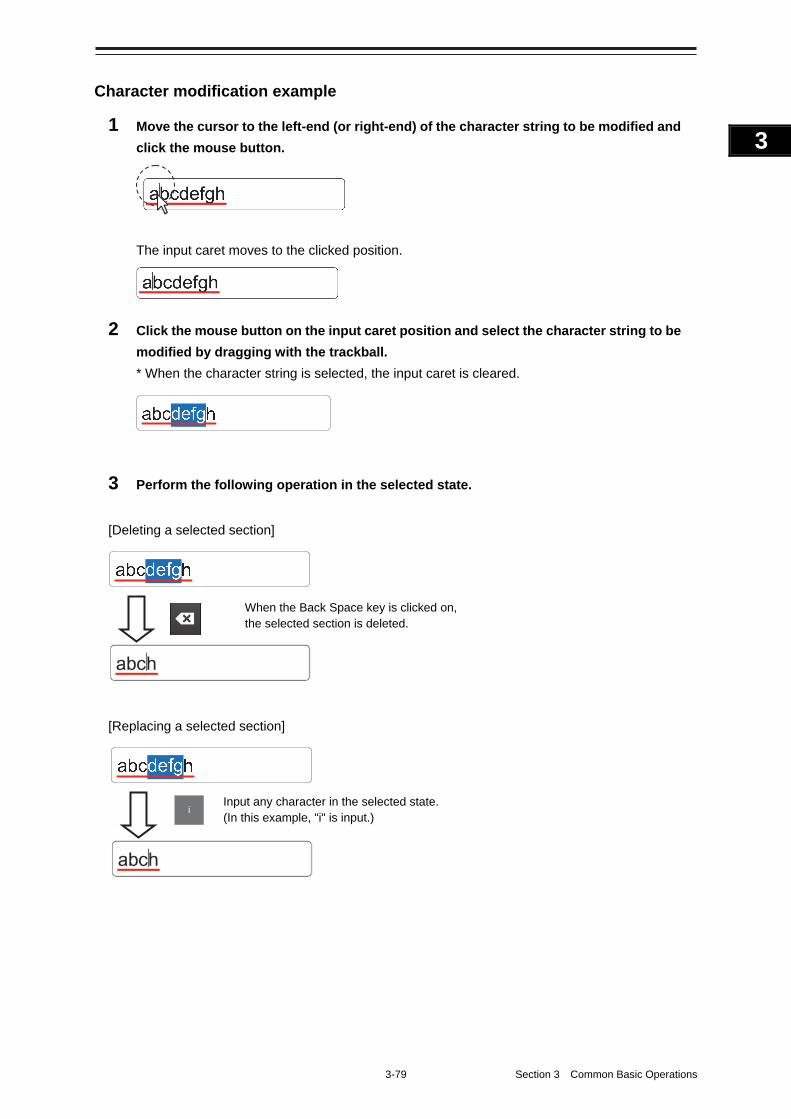
3-79 Section 3 Common Basic Operations
1
2
3
4
5
6
7
8
9
10
11
12
13
14
15
16
17
18
19
20
21
22
23
24
25
APP A
APP B
1
Character modification example
1 Move the cursor to the left-end (or right-end) of the character string to be modified and
click the mouse button.
The input caret moves to the clicked position.
2 Click the mouse button on the input caret position and select the character string to be
modified by dragging with the trackball.
* When the character string is selected, the input caret is cleared.
3 Perform the following operation in the selected state.
[Deleting a selected section]
[Replacing a selected section]
Input any character in the selected state. (In this example, "i" is input.) i
When the Back Space key is clicked on, the selected section is deleted.
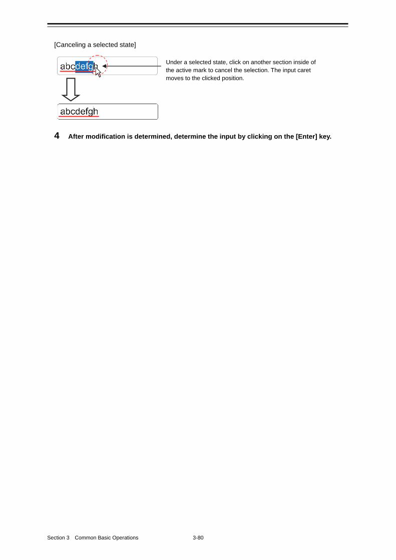
Section 3 Common Basic Operations 3-80
[Canceling a selected state]
4 After modification is determined, determine the input by clicking on the [Enter] key.
Under a selected state, click on another section inside of the active mark to cancel the selection. The input caret moves to the clicked position.
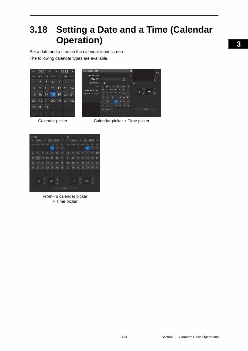
3-81 Section 3 Common Basic Operations
1
2
3
4
5
6
7
8
9
10
11
12
13
14
15
16
17
18
19
20
21
22
23
24
25
APP A
APP B
1
3.18 Setting a Date and a Time (Calendar Operation)
Set a date and a time on the calendar input screen.
The following calendar types are available.
Calendar picker Calendar picker + Time picker
From-To calendar picker + Time picker
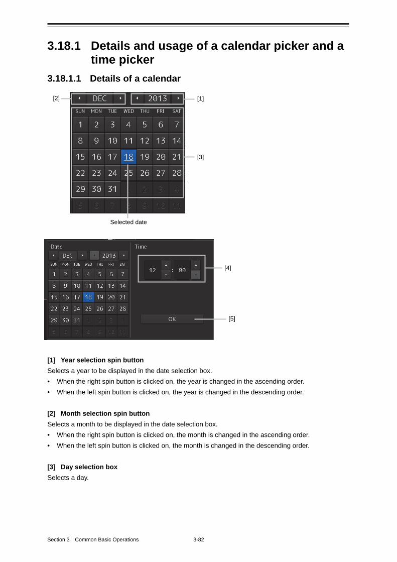
Section 3 Common Basic Operations 3-82
3.18.1 Details and usage of a calendar picker and a time picker
3.18.1.1 Details of a calendar
[1] Year selection spin button
Selects a year to be displayed in the date selection box.
• When the right spin button is clicked on, the year is changed in the ascending order.
• When the left spin button is clicked on, the year is changed in the descending order.
[2] Month selection spin button
Selects a month to be displayed in the date selection box.
• When the right spin button is clicked on, the month is changed in the ascending order.
• When the left spin button is clicked on, the month is changed in the descending order.
[3] Day selection box
Selects a day.
[1]
[3]
Selected date
[5]
[4]
[2]
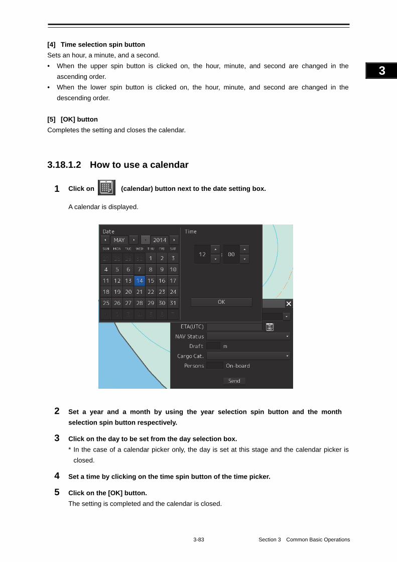
3-83 Section 3 Common Basic Operations
1
2
3
4
5
6
7
8
9
10
11
12
13
14
15
16
17
18
19
20
21
22
23
24
25
APP A
APP B
1
[4] Time selection spin button
Sets an hour, a minute, and a second.
• When the upper spin button is clicked on, the hour, minute, and second are changed in the
ascending order.
• When the lower spin button is clicked on, the hour, minute, and second are changed in the
descending order.
[5] [OK] button
Completes the setting and closes the calendar.
3.18.1.2 How to use a calendar
1 Click on (calendar) button next to the date setting box.
A calendar is displayed.
2 Set a year and a month by using the year selection spin button and the month
selection spin button respectively.
3 Click on the day to be set from the day selection box.
* In the case of a calendar picker only, the day is set at this stage and the calendar picker is
closed.
4 Set a time by clicking on the time spin button of the time picker.
5 Click on the [OK] button.
The setting is completed and the calendar is closed.
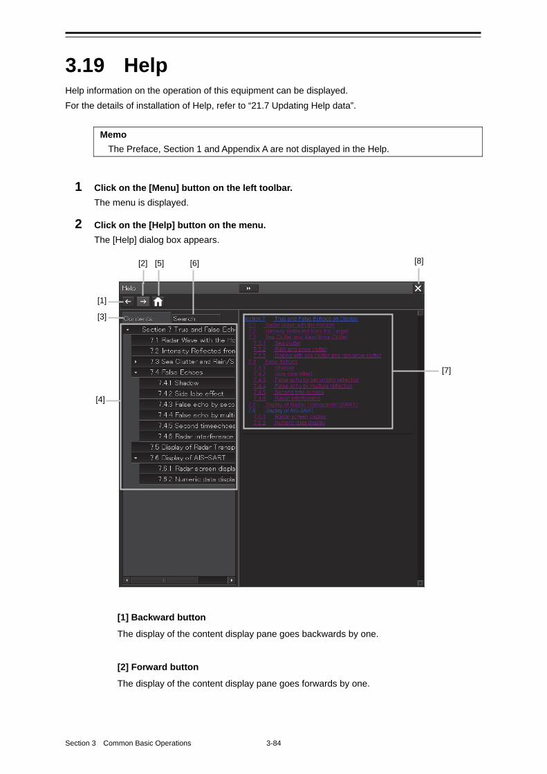
Section 3 Common Basic Operations 3-84
3.19 Help Help information on the operation of this equipment can be displayed.
For the details of installation of Help, refer to “21.7 Updating Help data”.
Memo
The Preface, Section 1 and Appendix A are not displayed in the Help.
1 Click on the [Menu] button on the left toolbar.
The menu is displayed.
2 Click on the [Help] button on the menu.
The [Help] dialog box appears.
[1] Backward button
The display of the content display pane goes backwards by one.
[2] Forward button
The display of the content display pane goes forwards by one.
[5] [6]
[1]
[7]
[8] [2]
[3]
[4]
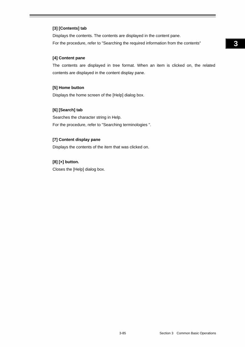
3-85 Section 3 Common Basic Operations
1
2
3
4
5
6
7
8
9
10
11
12
13
14
15
16
17
18
19
20
21
22
23
24
25
APP A
APP B
1
[3] [Contents] tab
Displays the contents. The contents are displayed in the content pane.
For the procedure, refer to "Searching the required information from the contents"
[4] Content pane
The contents are displayed in tree format. When an item is clicked on, the related
contents are displayed in the content display pane.
[5] Home button
Displays the home screen of the [Help] dialog box.
[6] [Search] tab
Searches the character string in Help.
For the procedure, refer to "Searching terminologies ".
[7] Content display pane
Displays the contents of the item that was clicked on.
[8] [×] button.
Closes the [Help] dialog box.
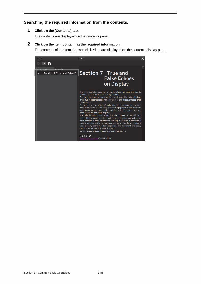
Section 3 Common Basic Operations 3-86
Searching the required information from the contents.
1 Click on the [Contents] tab.
The contents are displayed on the contents pane.
2 Click on the item containing the required information.
The contents of the item that was clicked on are displayed on the contents display pane.
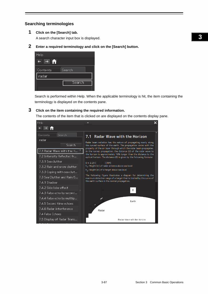
3-87 Section 3 Common Basic Operations
1
2
3
4
5
6
7
8
9
10
11
12
13
14
15
16
17
18
19
20
21
22
23
24
25
APP A
APP B
1
Searching terminologies
1 Click on the [Search] tab.
A search character input box is displayed.
2 Enter a required terminology and click on the [Search] button.
Search is performed within Help. When the applicable terminology is hit, the item containing the
terminology is displayed on the contents pane.
3 Click on the item containing the required information.
The contents of the item that is clicked on are displayed on the contents display pane.
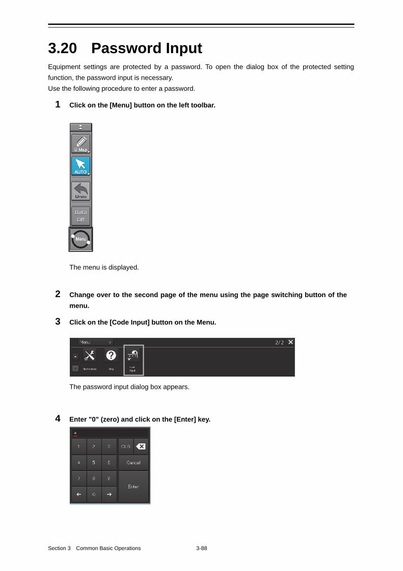
Section 3 Common Basic Operations 3-88
3.20 Password Input Equipment settings are protected by a password. To open the dialog box of the protected setting
function, the password input is necessary.
Use the following procedure to enter a password.
1 Click on the [Menu] button on the left toolbar.
The menu is displayed.
2 Change over to the second page of the menu using the page switching button of the
menu.
3 Click on the [Code Input] button on the Menu.
The password input dialog box appears.
4 Enter "0" (zero) and click on the [Enter] key.
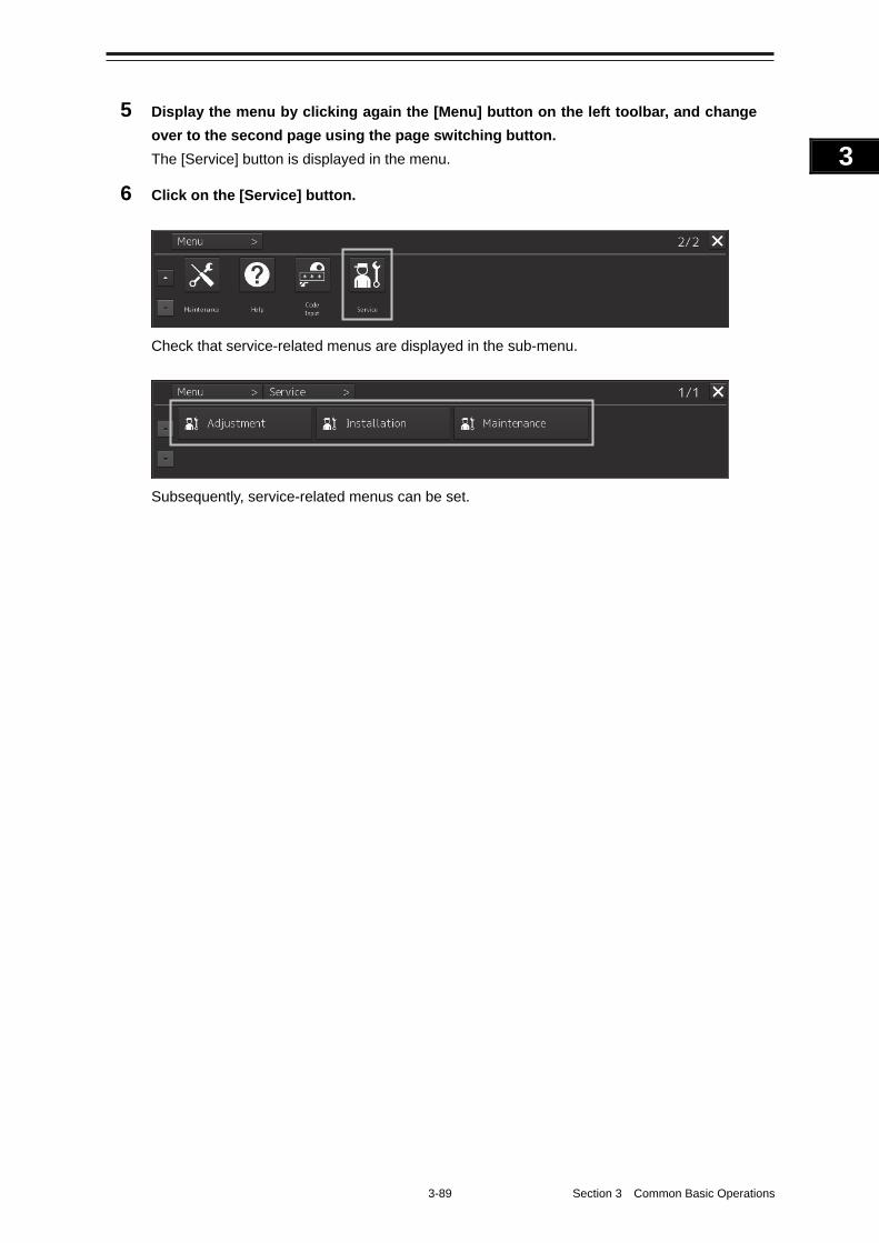
3-89 Section 3 Common Basic Operations
1
2
3
4
5
6
7
8
9
10
11
12
13
14
15
16
17
18
19
20
21
22
23
24
25
APP A
APP B
1
5 Display the menu by clicking again the [Menu] button on the left toolbar, and change
over to the second page using the page switching button.
The [Service] button is displayed in the menu.
6 Click on the [Service] button.
Check that service-related menus are displayed in the sub-menu.
Subsequently, service-related menus can be set.
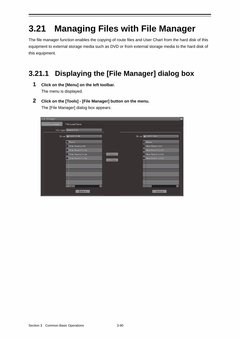
Section 3 Common Basic Operations 3-90
3.21 Managing Files with File Manager The file manager function enables the copying of route files and User Chart from the hard disk of this
equipment to external storage media such as DVD or from external storage media to the hard disk of
this equipment.
3.21.1 Displaying the [File Manager] dialog box
1 Click on the [Menu] on the left toolbar.
The menu is displayed.
2 Click on the [Tools] - [File Manager] button on the menu.
The [File Manager] dialog box appears.
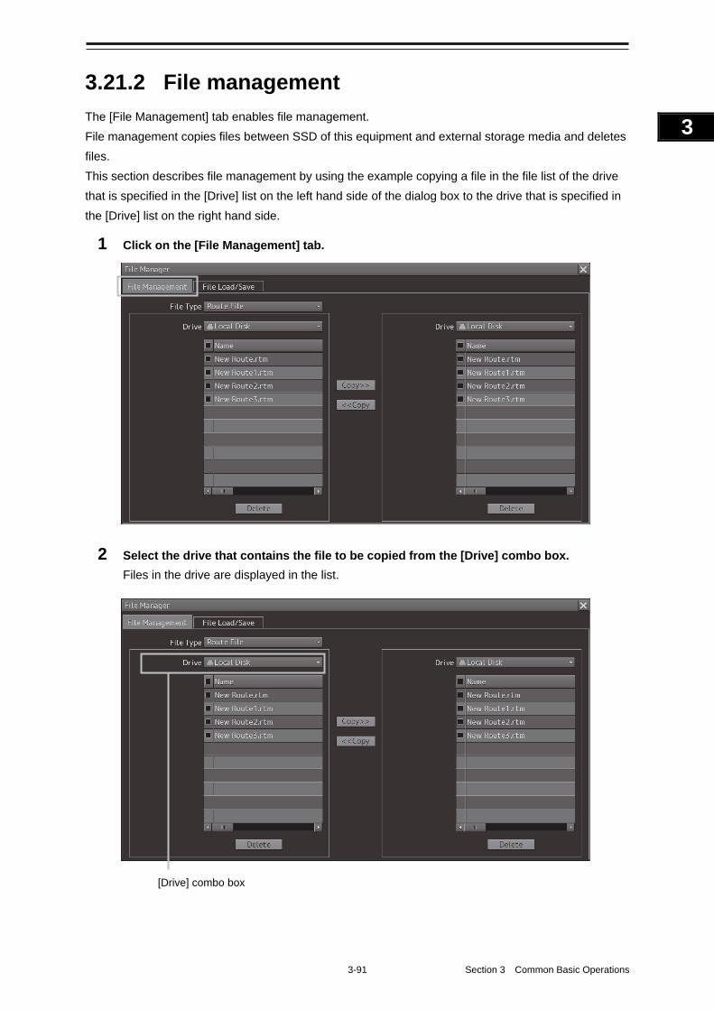
3-91 Section 3 Common Basic Operations
1
2
3
4
5
6
7
8
9
10
11
12
13
14
15
16
17
18
19
20
21
22
23
24
25
APP A
APP B
1
3.21.2 File management
The [File Management] tab enables file management.
File management copies files between SSD of this equipment and external storage media and deletes
files.
This section describes file management by using the example copying a file in the file list of the drive
that is specified in the [Drive] list on the left hand side of the dialog box to the drive that is specified in
the [Drive] list on the right hand side.
1 Click on the [File Management] tab.
2 Select the drive that contains the file to be copied from the [Drive] combo box.
Files in the drive are displayed in the list.
[Drive] combo box
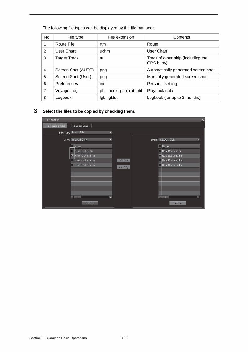
Section 3 Common Basic Operations 3-92
The following file types can be displayed by the file manager.
No. File type File extension Contents
1 Route File rtm Route
2 User Chart uchm User Chart
3 Target Track ttr Track of other ship (including the GPS buoy)
4 Screen Shot (AUTO) png Automatically generated screen shot
5 Screen Shot (User) png Manually generated screen shot
6 Preferences ini Personal setting
7 Voyage Log pbl, index, pbo, rot, pbt Playback data
8 Logbook lgb, lgblst Logbook (for up to 3 months)
3 Select the files to be copied by checking them.
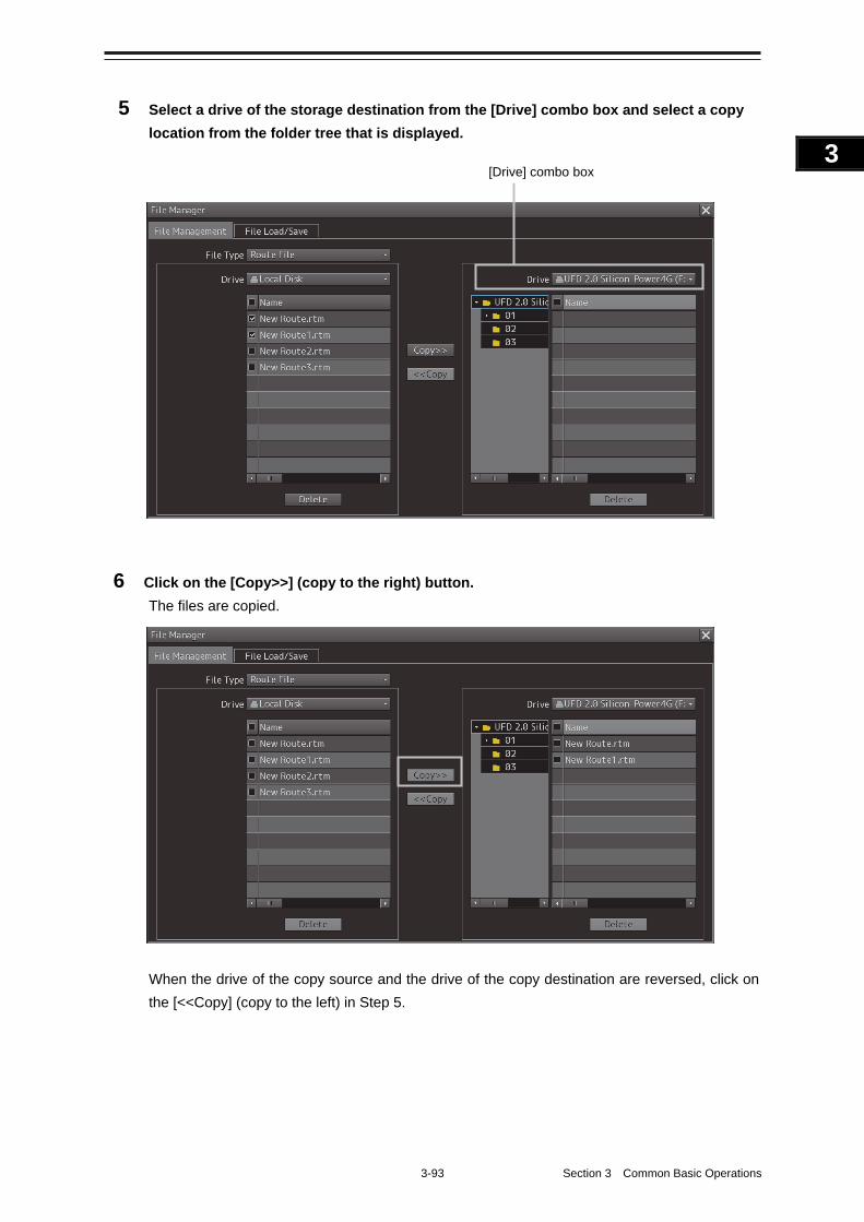
3-93 Section 3 Common Basic Operations
1
2
3
4
5
6
7
8
9
10
11
12
13
14
15
16
17
18
19
20
21
22
23
24
25
APP A
APP B
1
5 Select a drive of the storage destination from the [Drive] combo box and select a copy
location from the folder tree that is displayed.
6 Click on the [Copy>>] (copy to the right) button.
The files are copied.
When the drive of the copy source and the drive of the copy destination are reversed, click on
the [<<Copy] (copy to the left) in Step 5.
[Drive] combo box
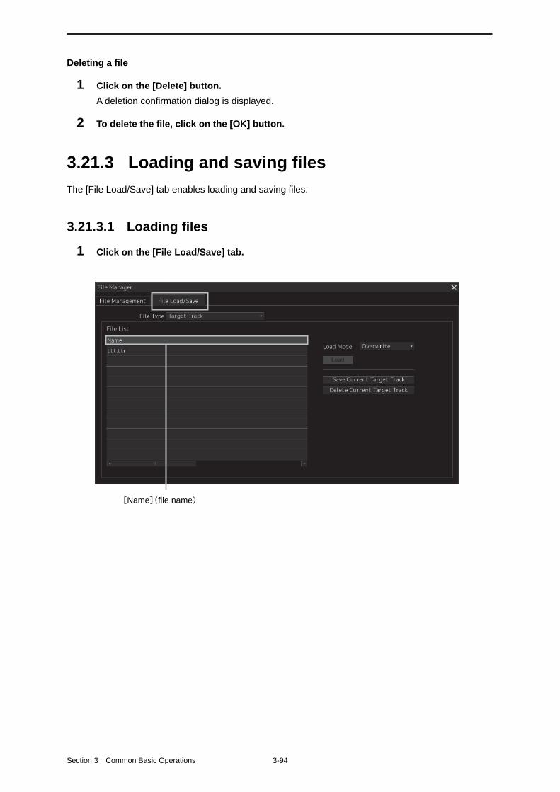
Section 3 Common Basic Operations 3-94
Deleting a file
1 Click on the [Delete] button.
A deletion confirmation dialog is displayed.
2 To delete the file, click on the [OK] button.
3.21.3 Loading and saving files
The [File Load/Save] tab enables loading and saving files.
3.21.3.1 Loading files
1 Click on the [File Load/Save] tab.
[Name](file name)
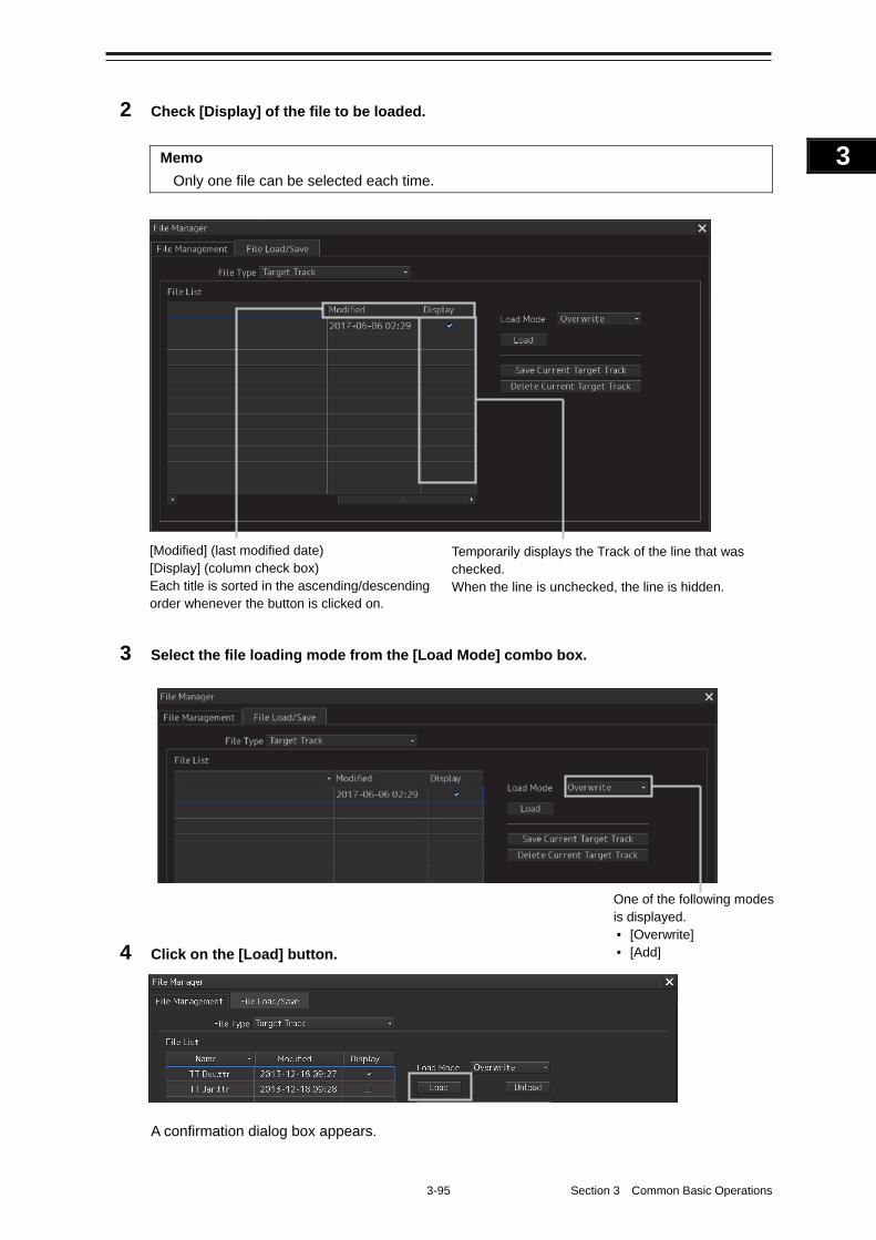
3-95 Section 3 Common Basic Operations
1
2
3
4
5
6
7
8
9
10
11
12
13
14
15
16
17
18
19
20
21
22
23
24
25
APP A
APP B
1
2 Check [Display] of the file to be loaded.
Memo
Only one file can be selected each time.
3 Select the file loading mode from the [Load Mode] combo box.
4 Click on the [Load] button.
A confirmation dialog box appears.
[Modified] (last modified date) [Display] (column check box) Each title is sorted in the ascending/descending order whenever the button is clicked on.
Temporarily displays the Track of the line that was checked. When the line is unchecked, the line is hidden.
One of the following modes is displayed. • [Overwrite] • [Add]
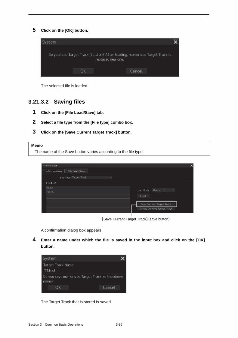
Section 3 Common Basic Operations 3-96
5 Click on the [OK] button.
The selected file is loaded.
3.21.3.2 Saving files
1 Click on the [File Load/Save] tab.
2 Select a file type from the [File type] combo box.
3 Click on the [Save Current Target Track] button.
Memo
The name of the Save button varies according to the file type.
A confirmation dialog box appears
4 Enter a name under which the file is saved in the input box and click on the [OK]
button.
The Target Track that is stored is saved.
[Save Current Target Track](save button)
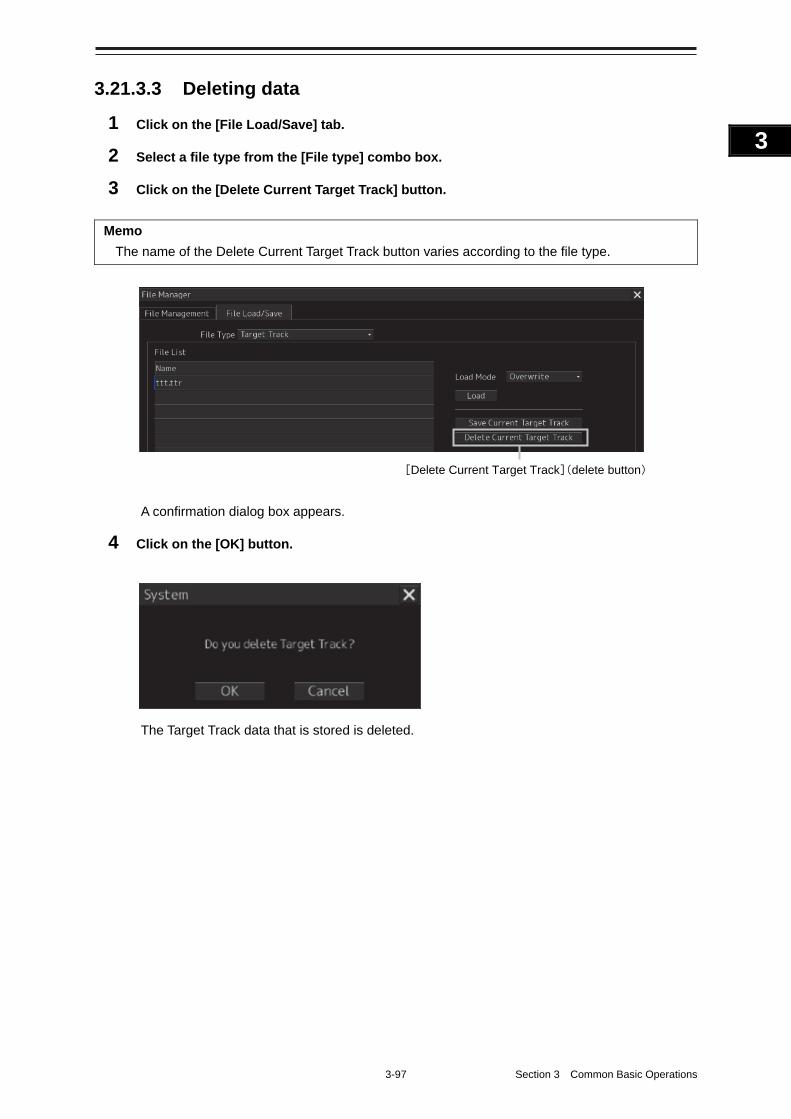
3-97 Section 3 Common Basic Operations
1
2
3
4
5
6
7
8
9
10
11
12
13
14
15
16
17
18
19
20
21
22
23
24
25
APP A
APP B
1
3.21.3.3 Deleting data
1 Click on the [File Load/Save] tab.
2 Select a file type from the [File type] combo box.
3 Click on the [Delete Current Target Track] button.
Memo
The name of the Delete Current Target Track button varies according to the file type.
A confirmation dialog box appears.
4 Click on the [OK] button.
The Target Track data that is stored is deleted.
[Delete Current Target Track](delete button)
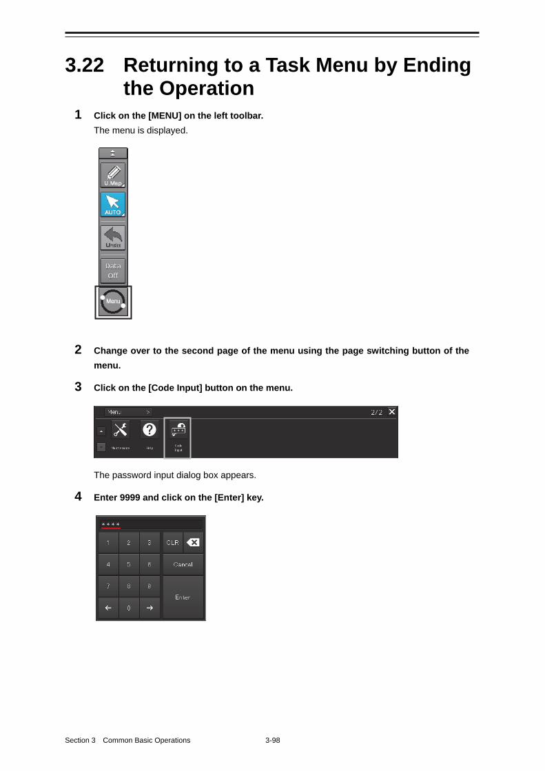
Section 3 Common Basic Operations 3-98
3.22 Returning to a Task Menu by Ending the Operation
1 Click on the [MENU] on the left toolbar.
The menu is displayed.
2 Change over to the second page of the menu using the page switching button of the
menu.
3 Click on the [Code Input] button on the menu.
The password input dialog box appears.
4 Enter 9999 and click on the [Enter] key.
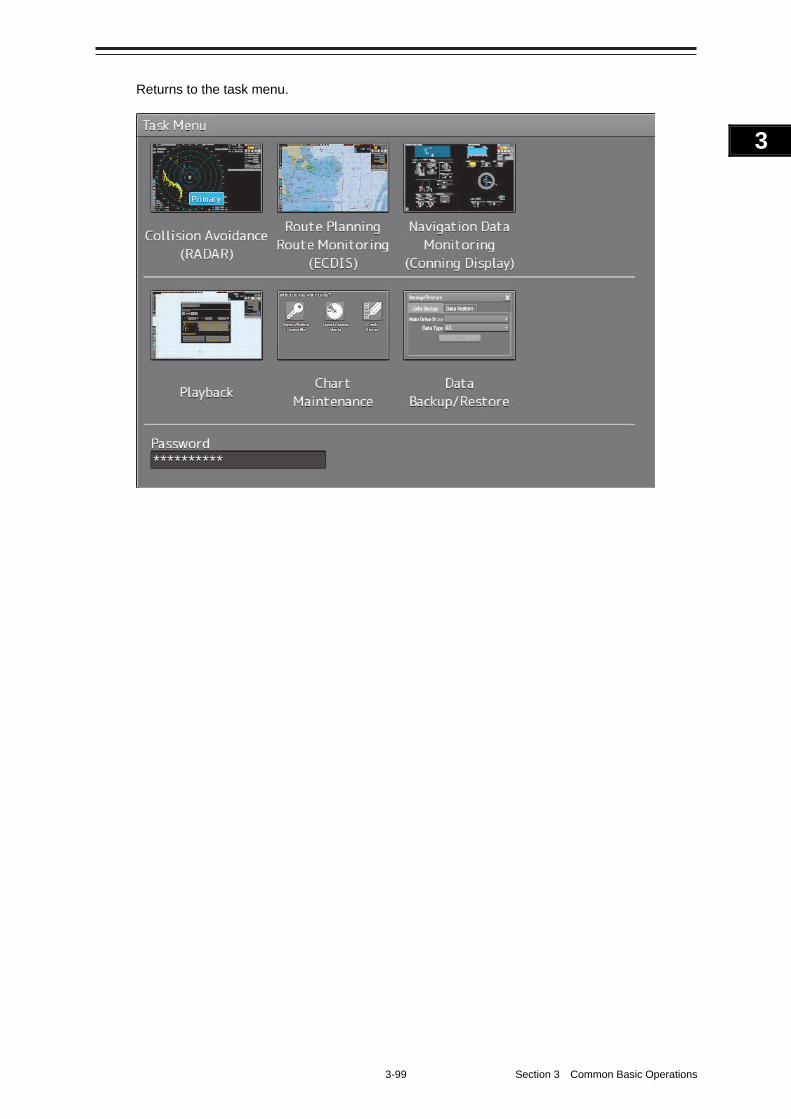
3-99 Section 3 Common Basic Operations
1
2
3
4
5
6
7
8
9
10
11
12
13
14
15
16
17
18
19
20
21
22
23
24
25
APP A
APP B
1
Returns to the task menu.
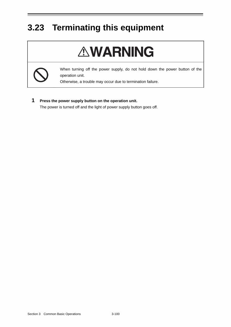
Section 3 Common Basic Operations 3-100
3.23 Terminating this equipment
When turning off the power supply, do not hold down the power button of the
operation unit.
Otherwise, a trouble may occur due to termination failure.
1 Press the power supply button on the operation unit.
The power is turned off and the light of power supply button goes off.
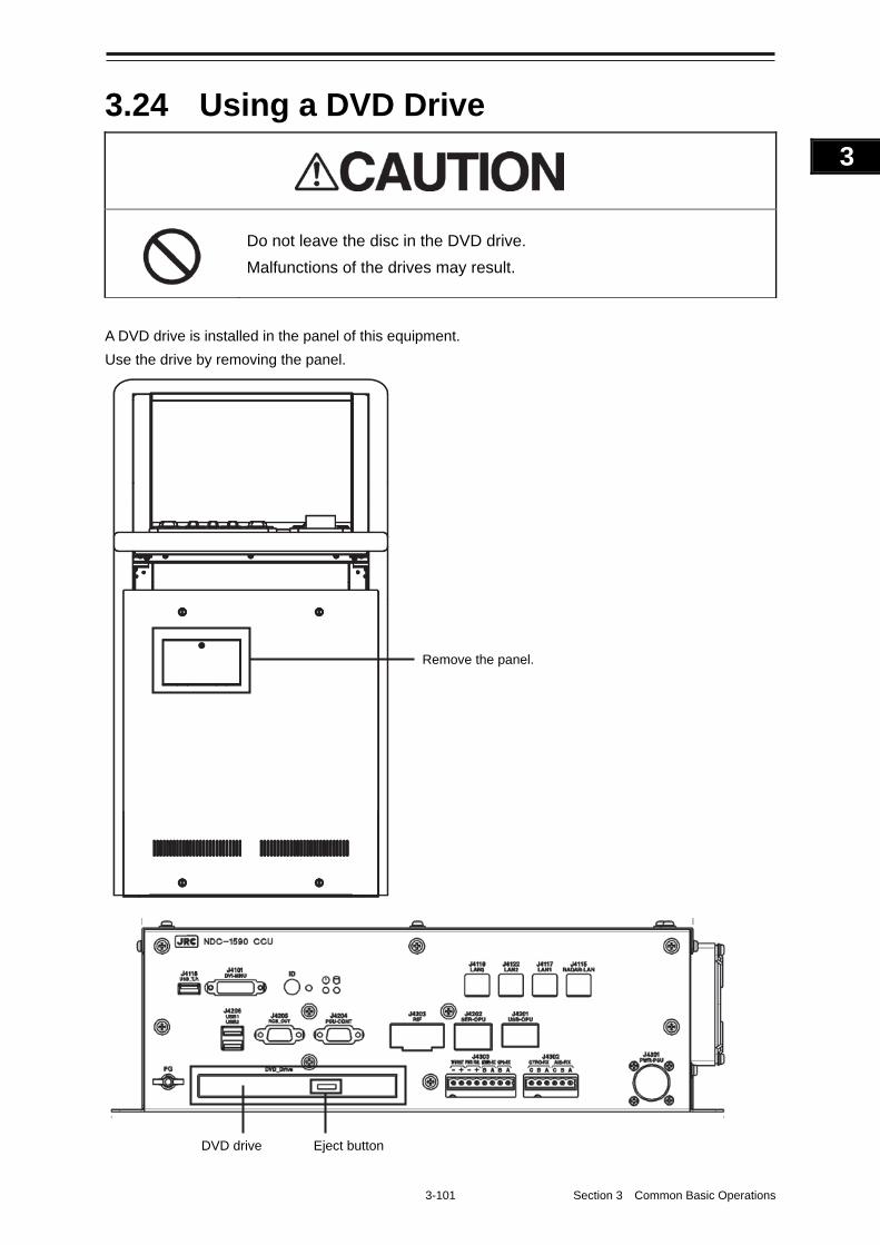
3-101 Section 3 Common Basic Operations
1
2
3
4
5
6
7
8
9
10
11
12
13
14
15
16
17
18
19
20
21
22
23
24
25
APP A
APP B
1
3.24 Using a DVD Drive
Do not leave the disc in the DVD drive.
Malfunctions of the drives may result.
A DVD drive is installed in the panel of this equipment.
Use the drive by removing the panel.
Remove the panel.
Eject button DVD drive

Section 3 Common Basic Operations 3-102
Note
Do not remove a DVD disk while the access lamp of the DVD drive is lit.
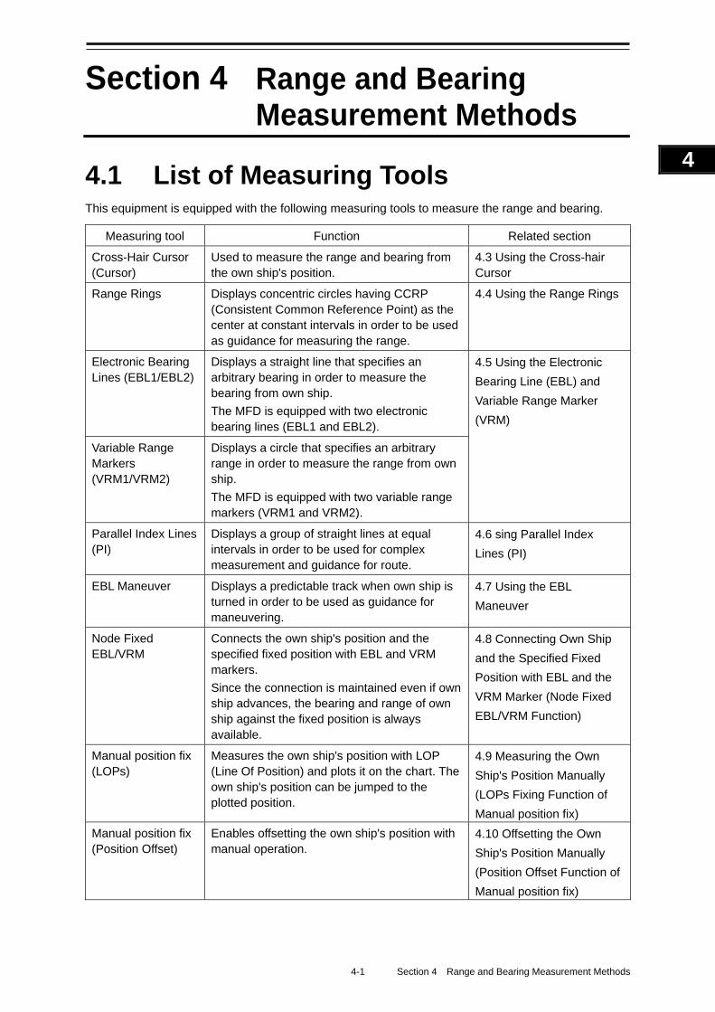
4-1 Section 4 Range and Bearing Measurement Methods
1
2
3
4
5
6
7
8
9
10
11
12
13
14
15
16
17
18
19
20
21
22
23
24
25
APP A
APP B
1
Section 4 Range and Bearing Measurement Methods
4.1 List of Measuring Tools This equipment is equipped with the following measuring tools to measure the range and bearing.
Measuring tool Function Related section
Cross-Hair Cursor (Cursor)
Used to measure the range and bearing from the own ship's position.
4.3 Using the Cross-hair Cursor
Range Rings Displays concentric circles having CCRP (Consistent Common Reference Point) as the center at constant intervals in order to be used as guidance for measuring the range.
4.4 Using the Range Rings
Electronic Bearing Lines (EBL1/EBL2)
Displays a straight line that specifies an arbitrary bearing in order to measure the bearing from own ship.
The MFD is equipped with two electronic bearing lines (EBL1 and EBL2).
4.5 Using the Electronic
Bearing Line (EBL) and
Variable Range Marker
(VRM)
Variable Range Markers (VRM1/VRM2)
Displays a circle that specifies an arbitrary range in order to measure the range from own ship.
The MFD is equipped with two variable range markers (VRM1 and VRM2).
Parallel Index Lines (PI)
Displays a group of straight lines at equal intervals in order to be used for complex measurement and guidance for route.
4.6 sing Parallel Index
Lines (PI)
EBL Maneuver Displays a predictable track when own ship is turned in order to be used as guidance for maneuvering.
4.7 Using the EBL
Maneuver
Node Fixed EBL/VRM
Connects the own ship's position and the specified fixed position with EBL and VRM markers.
Since the connection is maintained even if own ship advances, the bearing and range of own ship against the fixed position is always available.
4.8 Connecting Own Ship
and the Specified Fixed
Position with EBL and the
VRM Marker (Node Fixed
EBL/VRM Function)
Manual position fix (LOPs)
Measures the own ship's position with LOP (Line Of Position) and plots it on the chart. The own ship's position can be jumped to the plotted position.
4.9 Measuring the Own
Ship's Position Manually
(LOPs Fixing Function of
Manual position fix)
Manual position fix (Position Offset)
Enables offsetting the own ship's position with manual operation.
4.10 Offsetting the Own
Ship's Position Manually
(Position Offset Function of
Manual position fix)
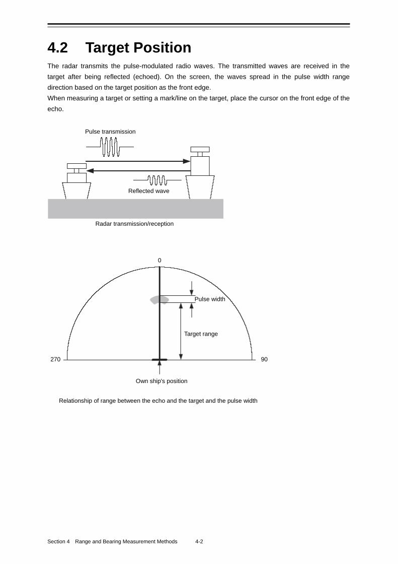
Section 4 Range and Bearing Measurement Methods 4-2
4.2 Target Position The radar transmits the pulse-modulated radio waves. The transmitted waves are received in the
target after being reflected (echoed). On the screen, the waves spread in the pulse width range
direction based on the target position as the front edge.
When measuring a target or setting a mark/line on the target, place the cursor on the front edge of the
echo.
Radar transmission/reception
Relationship of range between the echo and the target and the pulse width
Pulse transmission
Reflected wave
270 90
0
Pulse width
Target range
Own ship's position
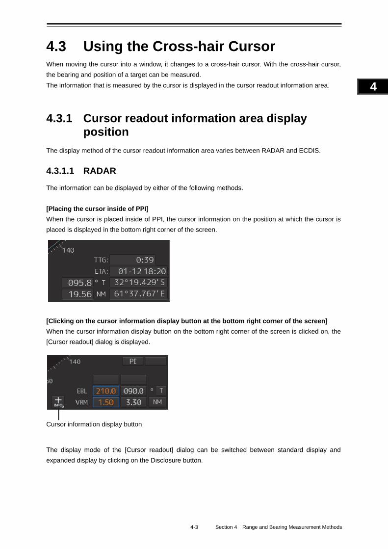
4-3 Section 4 Range and Bearing Measurement Methods
1
2
3
4
5
6
7
8
9
10
11
12
13
14
15
16
17
18
19
20
21
22
23
24
25
APP A
APP B
1
4.3 Using the Cross-hair Cursor When moving the cursor into a window, it changes to a cross-hair cursor. With the cross-hair cursor,
the bearing and position of a target can be measured.
The information that is measured by the cursor is displayed in the cursor readout information area.
4.3.1 Cursor readout information area display position
The display method of the cursor readout information area varies between RADAR and ECDIS.
4.3.1.1 RADAR
The information can be displayed by either of the following methods.
[Placing the cursor inside of PPI]
When the cursor is placed inside of PPI, the cursor information on the position at which the cursor is
placed is displayed in the bottom right corner of the screen.
[Clicking on the cursor information display button at the bottom right corner of the screen]
When the cursor information display button on the bottom right corner of the screen is clicked on, the
[Cursor readout] dialog is displayed.
The display mode of the [Cursor readout] dialog can be switched between standard display and
expanded display by clicking on the Disclosure button.
Cursor information display button
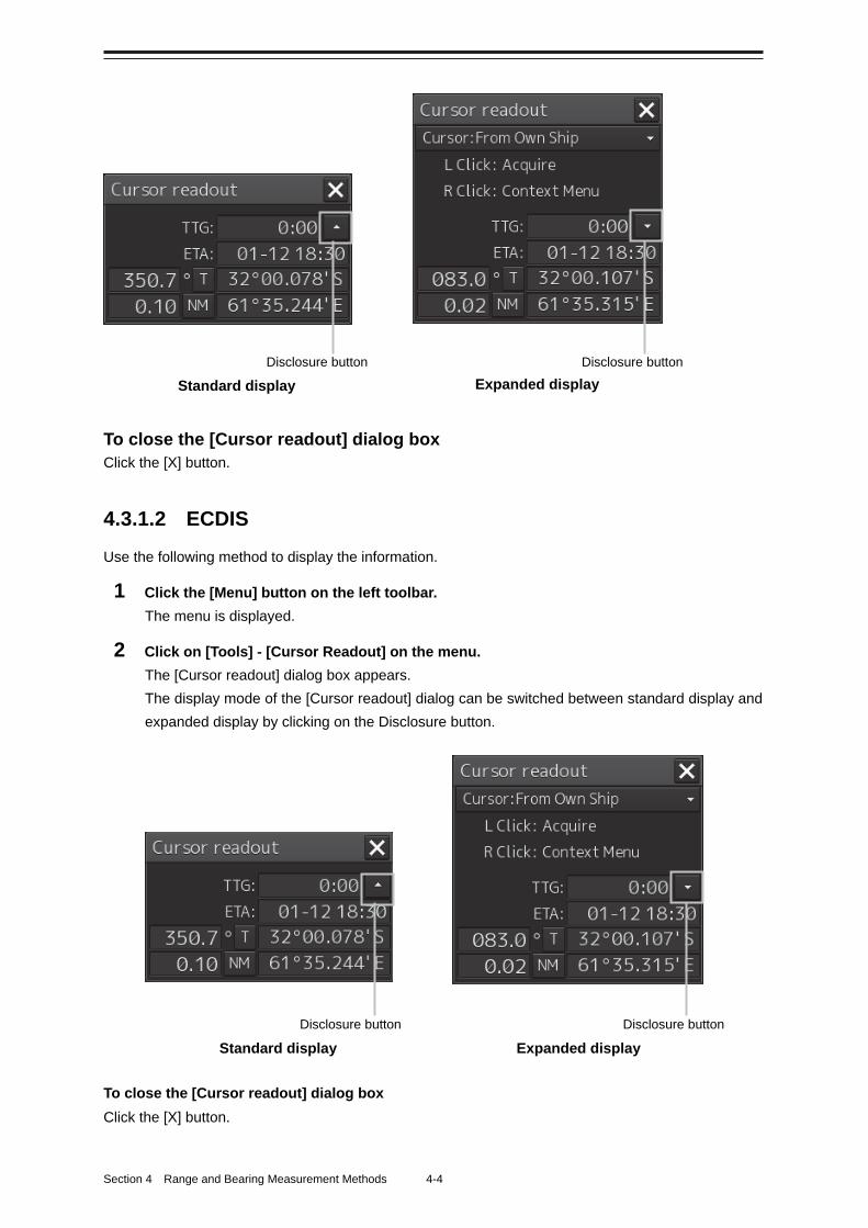
Section 4 Range and Bearing Measurement Methods 4-4
To close the [Cursor readout] dialog box Click the [X] button.
4.3.1.2 ECDIS
Use the following method to display the information.
1 Click the [Menu] button on the left toolbar.
The menu is displayed.
2 Click on [Tools] - [Cursor Readout] on the menu.
The [Cursor readout] dialog box appears.
The display mode of the [Cursor readout] dialog can be switched between standard display and
expanded display by clicking on the Disclosure button.
To close the [Cursor readout] dialog box
Click the [X] button.
Disclosure button Disclosure button
Standard display Expanded display
Disclosure button Disclosure button Standard display Expanded display
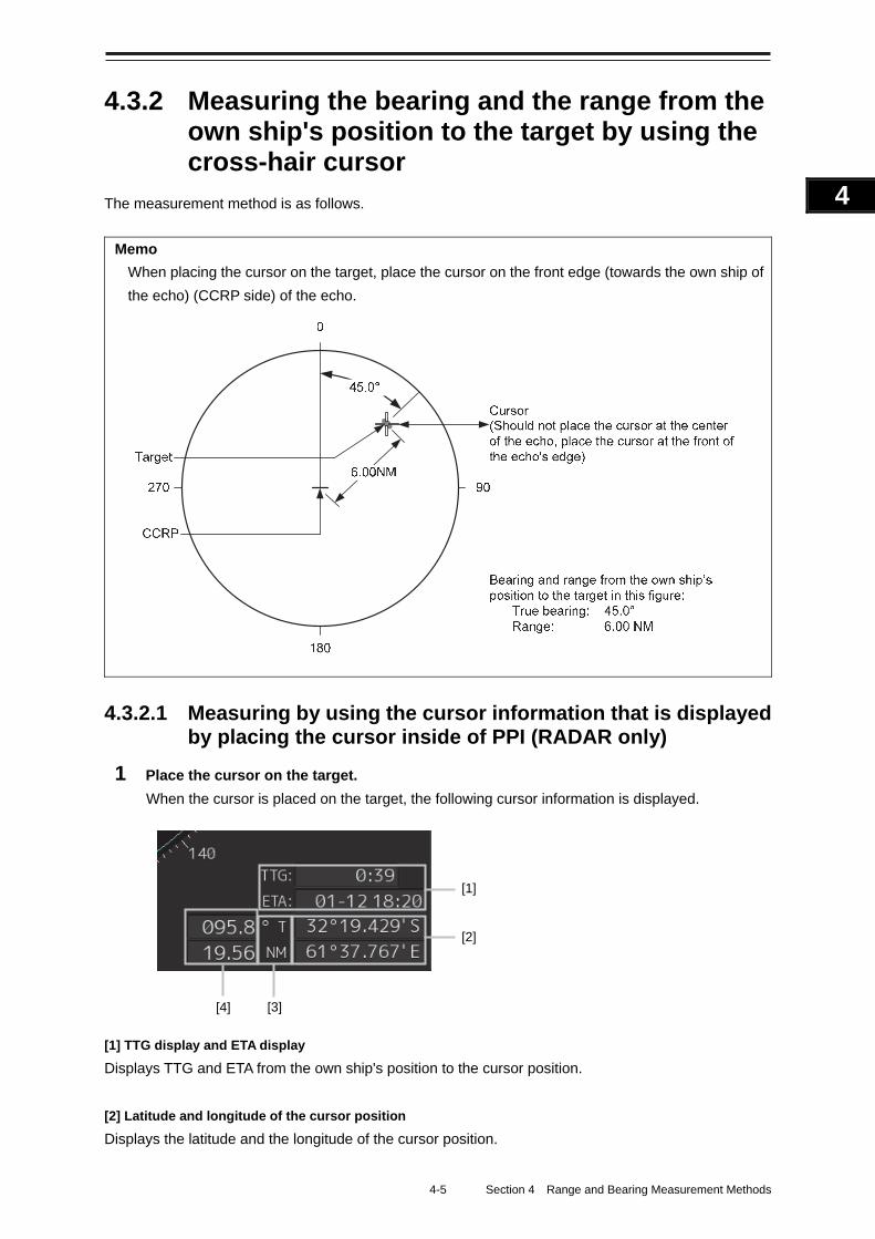
4-5 Section 4 Range and Bearing Measurement Methods
1
2
3
4
5
6
7
8
9
10
11
12
13
14
15
16
17
18
19
20
21
22
23
24
25
APP A
APP B
1
4.3.2 Measuring the bearing and the range from the own ship's position to the target by using the cross-hair cursor
The measurement method is as follows.
Memo
When placing the cursor on the target, place the cursor on the front edge (towards the own ship of
the echo) (CCRP side) of the echo.
4.3.2.1 Measuring by using the cursor information that is displayed by placing the cursor inside of PPI (RADAR only)
1 Place the cursor on the target.
When the cursor is placed on the target, the following cursor information is displayed.
[1] TTG display and ETA display
Displays TTG and ETA from the own ship's position to the cursor position.
[2] Latitude and longitude of the cursor position
Displays the latitude and the longitude of the cursor position.
[1]
[2]
[4]
[3]
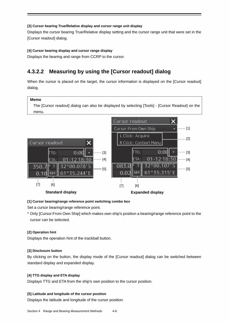
Section 4 Range and Bearing Measurement Methods 4-6
[3] Cursor bearing True/Relative display and cursor range unit display
Displays the cursor bearing True/Relative display setting and the cursor range unit that were set in the
[Cursor readout] dialog.
[4] Cursor bearing display and cursor range display
Displays the bearing and range from CCRP to the cursor.
4.3.2.2 Measuring by using the [Cursor readout] dialog
When the cursor is placed on the target, the cursor information is displayed on the [Cursor readout]
dialog.
Memo
The [Cursor readout] dialog can also be displayed by selecting [Tools] - [Cursor Readout] on the
menu.
[1] Cursor bearing/range reference point switching combo box
Set a cursor bearing/range reference point.
* Only [Cursor:From Own Ship] which makes own ship's position a bearing/range reference point to the
cursor can be selected.
[2] Operation hint
Displays the operation hint of the trackball button.
[3] Disclosure button
By clicking on the button, the display mode of the [Cursor readout] dialog can be switched between
standard display and expanded display.
[4] TTG display and ETA display
Displays TTG and ETA from the ship's own position to the cursor position.
[5] Latitude and longitude of the cursor position
Displays the latitude and longitude of the cursor position.
[3] [3]
[1]
[2]
[5]
[6] [6] [7] [7]
[4] [4]
[5]
Standard display Expanded display
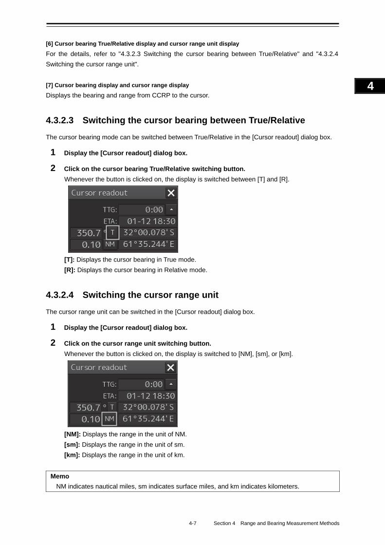
4-7 Section 4 Range and Bearing Measurement Methods
1
2
3
4
5
6
7
8
9
10
11
12
13
14
15
16
17
18
19
20
21
22
23
24
25
APP A
APP B
1
[6] Cursor bearing True/Relative display and cursor range unit display
For the details, refer to "4.3.2.3 Switching the cursor bearing between True/Relative" and "4.3.2.4
Switching the cursor range unit".
[7] Cursor bearing display and cursor range display
Displays the bearing and range from CCRP to the cursor.
4.3.2.3 Switching the cursor bearing between True/Relative
The cursor bearing mode can be switched between True/Relative in the [Cursor readout] dialog box.
1 Display the [Cursor readout] dialog box.
2 Click on the cursor bearing True/Relative switching button.
Whenever the button is clicked on, the display is switched between [T] and [R].
[T]: Displays the cursor bearing in True mode.
[R]: Displays the cursor bearing in Relative mode.
4.3.2.4 Switching the cursor range unit
The cursor range unit can be switched in the [Cursor readout] dialog box.
1 Display the [Cursor readout] dialog box.
2 Click on the cursor range unit switching button.
Whenever the button is clicked on, the display is switched to [NM], [sm], or [km].
[NM]: Displays the range in the unit of NM.
[sm]: Displays the range in the unit of sm.
[km]: Displays the range in the unit of km.
Memo
NM indicates nautical miles, sm indicates surface miles, and km indicates kilometers.
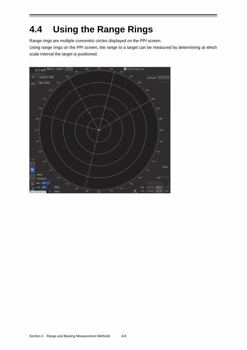
Section 4 Range and Bearing Measurement Methods 4-8
4.4 Using the Range Rings Range rings are multiple concentric circles displayed on the PPI screen.
Using range rings on the PPI screen, the range to a target can be measured by determining at which
scale interval the target is positioned.
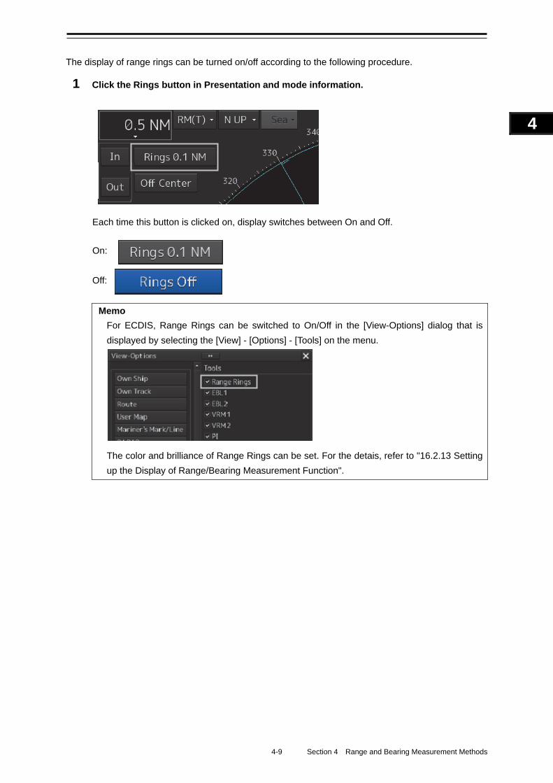
4-9 Section 4 Range and Bearing Measurement Methods
1
2
3
4
5
6
7
8
9
10
11
12
13
14
15
16
17
18
19
20
21
22
23
24
25
APP A
APP B
1
The display of range rings can be turned on/off according to the following procedure.
1 Click the Rings button in Presentation and mode information.
Each time this button is clicked on, display switches between On and Off.
On:
Off:
Memo
For ECDIS, Range Rings can be switched to On/Off in the [View-Options] dialog that is
displayed by selecting the [View] - [Options] - [Tools] on the menu.
The color and brilliance of Range Rings can be set. For the detais, refer to "16.2.13 Setting
up the Display of Range/Bearing Measurement Function".
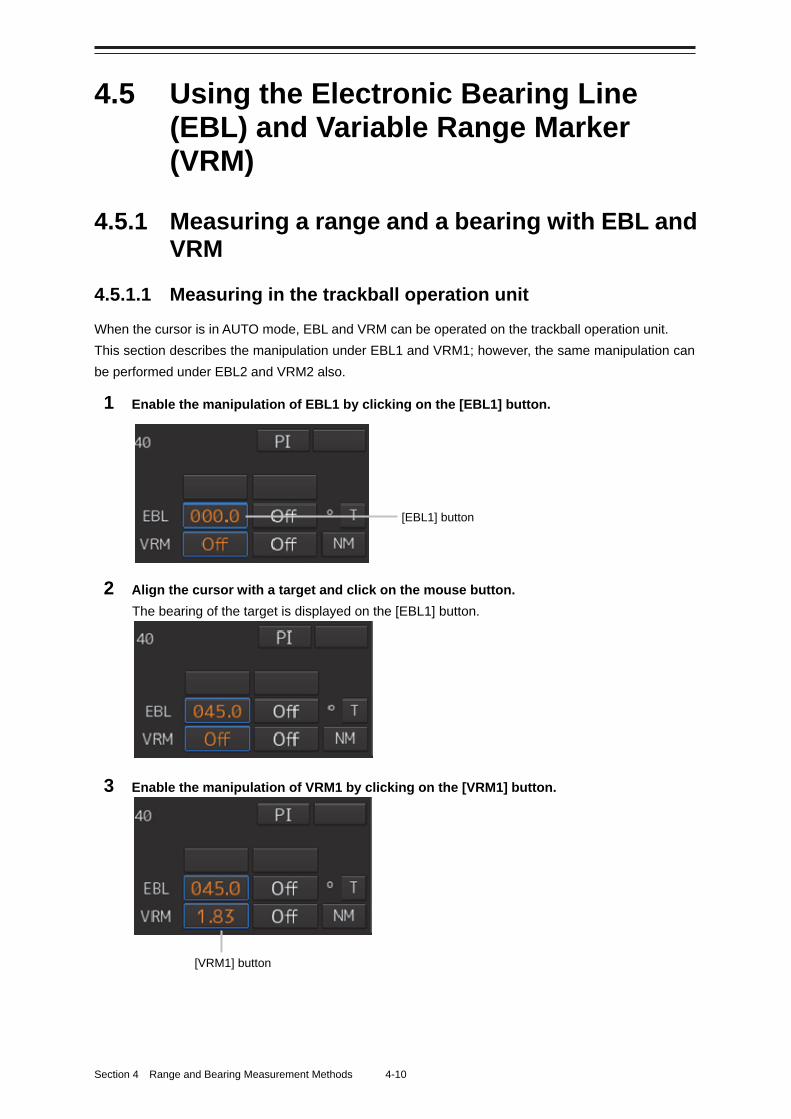
Section 4 Range and Bearing Measurement Methods 4-10
4.5 Using the Electronic Bearing Line (EBL) and Variable Range Marker (VRM)
4.5.1 Measuring a range and a bearing with EBL and VRM
4.5.1.1 Measuring in the trackball operation unit
When the cursor is in AUTO mode, EBL and VRM can be operated on the trackball operation unit.
This section describes the manipulation under EBL1 and VRM1; however, the same manipulation can
be performed under EBL2 and VRM2 also.
1 Enable the manipulation of EBL1 by clicking on the [EBL1] button.
2 Align the cursor with a target and click on the mouse button.
The bearing of the target is displayed on the [EBL1] button.
3 Enable the manipulation of VRM1 by clicking on the [VRM1] button.
[EBL1] button
[VRM1] button
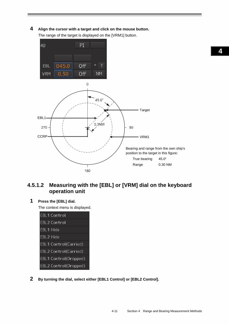
4-11 Section 4 Range and Bearing Measurement Methods
1
2
3
4
5
6
7
8
9
10
11
12
13
14
15
16
17
18
19
20
21
22
23
24
25
APP A
APP B
1
4 Align the cursor with a target and click on the mouse button.
The range of the target is displayed on the [VRM1] button.
4.5.1.2 Measuring with the [EBL] or [VRM] dial on the keyboard operation unit
1 Press the [EBL] dial.
The context menu is displayed.
2 By turning the dial, select either [EBL1 Control] or [EBL2 Control].
VRM1
Target
CCRP
EBL1
Bearing and range from the own ship's position to the target in this figure:
True bearing 45.0
Range 0.30 NM
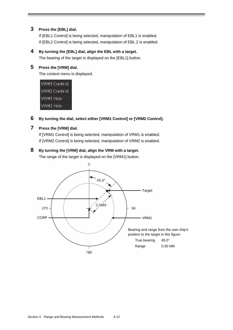
Section 4 Range and Bearing Measurement Methods 4-12
3 Press the [EBL] dial.
If [EBL1 Control] is being selected, manipulation of EBL1 is enabled.
If [EBL2 Control] is being selected, manipulation of EBL 2 is enabled.
4 By turning the [EBL] dial, align the EBL with a target.
The bearing of the target is displayed on the [EBL1] button.
5 Press the [VRM] dial.
The context menu is displayed.
6 By turning the dial, select either [VRM1 Control] or [VRM2 Control].
7 Press the [VRM] dial.
If [VRM1 Control] is being selected, manipulation of VRM1 is enabled.
If [VRM2 Control] is being selected, manipulation of VRM2 is enabled.
8 By turning the [VRM] dial, align the VRM with a target.
The range of the target is displayed on the [VRM1] button.
VRM1
Target
CCRP
EBL1
Bearing and range from the own ship's position to the target in this figure:
True bearing 45.0
Range 0.30 NM
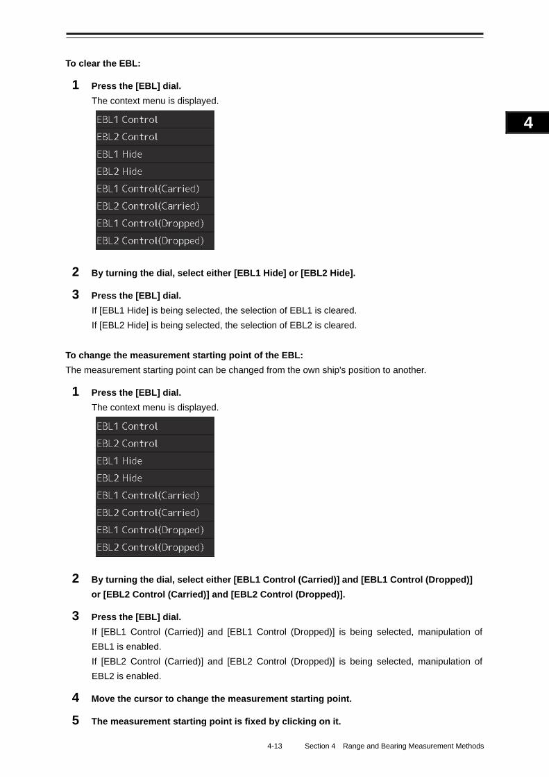
4-13 Section 4 Range and Bearing Measurement Methods
1
2
3
4
5
6
7
8
9
10
11
12
13
14
15
16
17
18
19
20
21
22
23
24
25
APP A
APP B
1
To clear the EBL:
1 Press the [EBL] dial.
The context menu is displayed.
2 By turning the dial, select either [EBL1 Hide] or [EBL2 Hide].
3 Press the [EBL] dial.
If [EBL1 Hide] is being selected, the selection of EBL1 is cleared.
If [EBL2 Hide] is being selected, the selection of EBL2 is cleared.
To change the measurement starting point of the EBL:
The measurement starting point can be changed from the own ship's position to another.
1 Press the [EBL] dial.
The context menu is displayed.
2 By turning the dial, select either [EBL1 Control (Carried)] and [EBL1 Control (Dropped)]
or [EBL2 Control (Carried)] and [EBL2 Control (Dropped)].
3 Press the [EBL] dial.
If [EBL1 Control (Carried)] and [EBL1 Control (Dropped)] is being selected, manipulation of
EBL1 is enabled.
If [EBL2 Control (Carried)] and [EBL2 Control (Dropped)] is being selected, manipulation of
EBL2 is enabled.
4 Move the cursor to change the measurement starting point.
5 The measurement starting point is fixed by clicking on it.
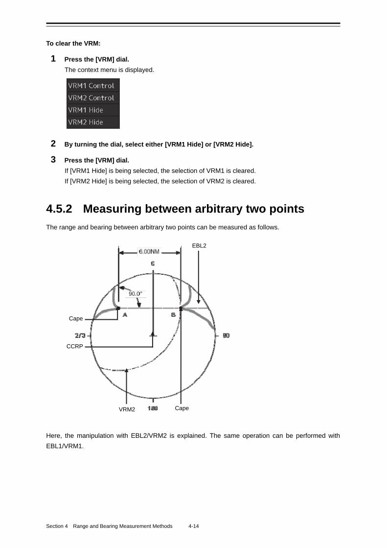
Section 4 Range and Bearing Measurement Methods 4-14
To clear the VRM:
1 Press the [VRM] dial.
The context menu is displayed.
2 By turning the dial, select either [VRM1 Hide] or [VRM2 Hide].
3 Press the [VRM] dial.
If [VRM1 Hide] is being selected, the selection of VRM1 is cleared.
If [VRM2 Hide] is being selected, the selection of VRM2 is cleared.
4.5.2 Measuring between arbitrary two points
The range and bearing between arbitrary two points can be measured as follows.
Here, the manipulation with EBL2/VRM2 is explained. The same operation can be performed with
EBL1/VRM1.
EBL2
Cape VRM2
CCRP
Cape
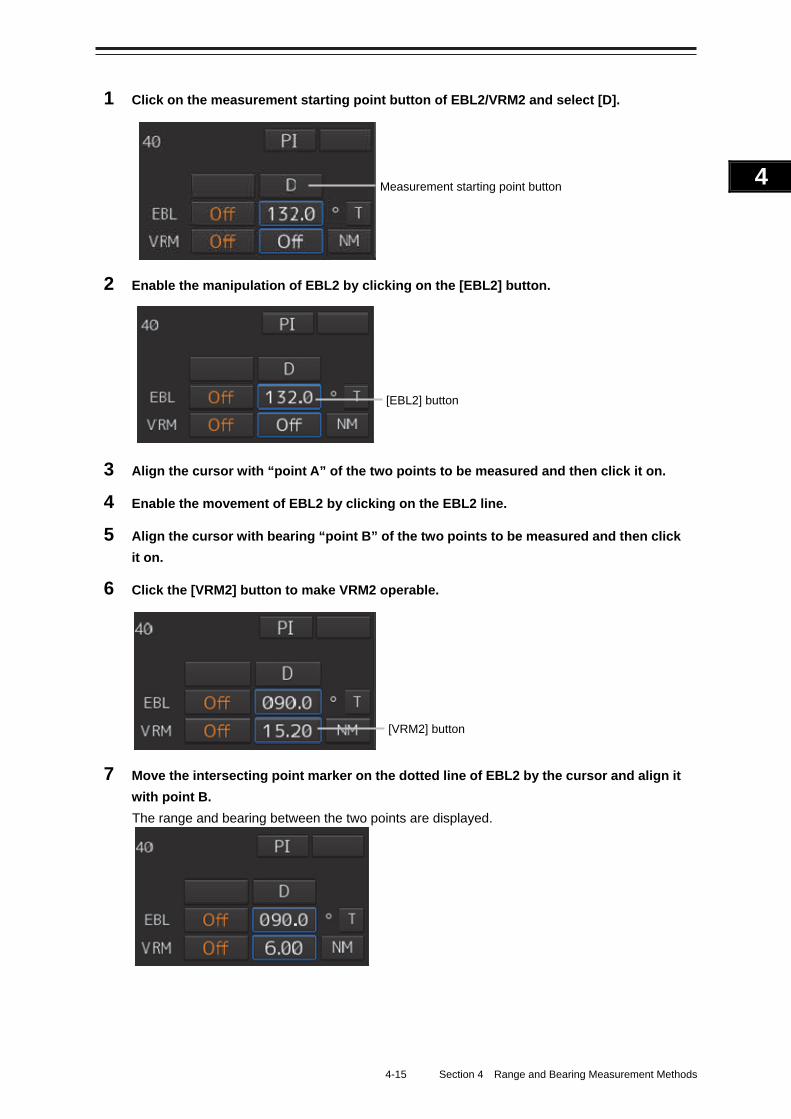
4-15 Section 4 Range and Bearing Measurement Methods
1
2
3
4
5
6
7
8
9
10
11
12
13
14
15
16
17
18
19
20
21
22
23
24
25
APP A
APP B
1
1 Click on the measurement starting point button of EBL2/VRM2 and select [D].
2 Enable the manipulation of EBL2 by clicking on the [EBL2] button.
3 Align the cursor with “point A” of the two points to be measured and then click it on.
4 Enable the movement of EBL2 by clicking on the EBL2 line.
5 Align the cursor with bearing “point B” of the two points to be measured and then click
it on.
6 Click the [VRM2] button to make VRM2 operable.
7 Move the intersecting point marker on the dotted line of EBL2 by the cursor and align it
with point B.
The range and bearing between the two points are displayed.
[VRM2] button
[EBL2] button
Measurement starting point button
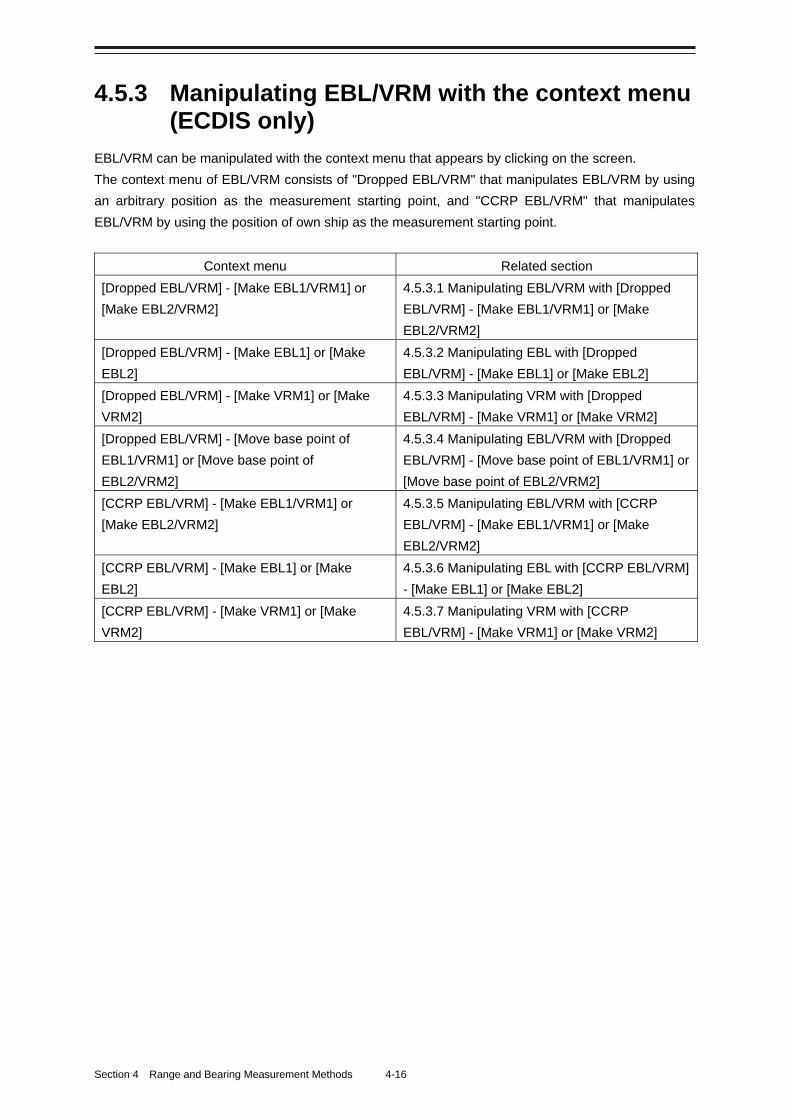
Section 4 Range and Bearing Measurement Methods 4-16
4.5.3 Manipulating EBL/VRM with the context menu (ECDIS only)
EBL/VRM can be manipulated with the context menu that appears by clicking on the screen.
The context menu of EBL/VRM consists of "Dropped EBL/VRM" that manipulates EBL/VRM by using
an arbitrary position as the measurement starting point, and "CCRP EBL/VRM" that manipulates
EBL/VRM by using the position of own ship as the measurement starting point.
Context menu Related section
[Dropped EBL/VRM] - [Make EBL1/VRM1] or
[Make EBL2/VRM2]
4.5.3.1 Manipulating EBL/VRM with [Dropped
EBL/VRM] - [Make EBL1/VRM1] or [Make
EBL2/VRM2]
[Dropped EBL/VRM] - [Make EBL1] or [Make
EBL2]
4.5.3.2 Manipulating EBL with [Dropped
EBL/VRM] - [Make EBL1] or [Make EBL2]
[Dropped EBL/VRM] - [Make VRM1] or [Make
VRM2]
4.5.3.3 Manipulating VRM with [Dropped
EBL/VRM] - [Make VRM1] or [Make VRM2]
[Dropped EBL/VRM] - [Move base point of
EBL1/VRM1] or [Move base point of
EBL2/VRM2]
4.5.3.4 Manipulating EBL/VRM with [Dropped
EBL/VRM] - [Move base point of EBL1/VRM1] or
[Move base point of EBL2/VRM2]
[CCRP EBL/VRM] - [Make EBL1/VRM1] or
[Make EBL2/VRM2]
4.5.3.5 Manipulating EBL/VRM with [CCRP
EBL/VRM] - [Make EBL1/VRM1] or [Make
EBL2/VRM2]
[CCRP EBL/VRM] - [Make EBL1] or [Make
EBL2]
4.5.3.6 Manipulating EBL with [CCRP EBL/VRM]
- [Make EBL1] or [Make EBL2]
[CCRP EBL/VRM] - [Make VRM1] or [Make
VRM2]
4.5.3.7 Manipulating VRM with [CCRP
EBL/VRM] - [Make VRM1] or [Make VRM2]
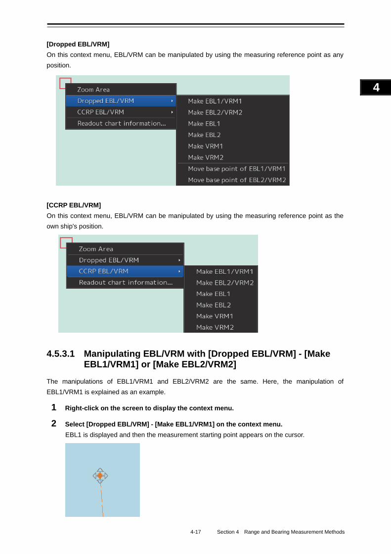
4-17 Section 4 Range and Bearing Measurement Methods
1
2
3
4
5
6
7
8
9
10
11
12
13
14
15
16
17
18
19
20
21
22
23
24
25
APP A
APP B
1
[Dropped EBL/VRM]
On this context menu, EBL/VRM can be manipulated by using the measuring reference point as any
position.
[CCRP EBL/VRM]
On this context menu, EBL/VRM can be manipulated by using the measuring reference point as the
own ship's position.
4.5.3.1 Manipulating EBL/VRM with [Dropped EBL/VRM] - [Make EBL1/VRM1] or [Make EBL2/VRM2]
The manipulations of EBL1/VRM1 and EBL2/VRM2 are the same. Here, the manipulation of
EBL1/VRM1 is explained as an example.
1 Right-click on the screen to display the context menu.
2 Select [Dropped EBL/VRM] - [Make EBL1/VRM1] on the context menu.
EBL1 is displayed and then the measurement starting point appears on the cursor.
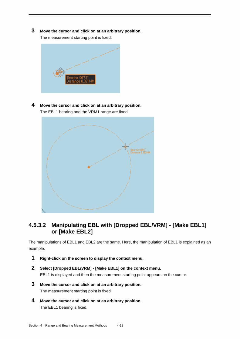
Section 4 Range and Bearing Measurement Methods 4-18
3 Move the cursor and click on at an arbitrary position.
The measurement starting point is fixed.
4 Move the cursor and click on at an arbitrary position.
The EBL1 bearing and the VRM1 range are fixed.
4.5.3.2 Manipulating EBL with [Dropped EBL/VRM] - [Make EBL1] or [Make EBL2]
The manipulations of EBL1 and EBL2 are the same. Here, the manipulation of EBL1 is explained as an
example.
1 Right-click on the screen to display the context menu.
2 Select [Dropped EBL/VRM] - [Make EBL1] on the context menu.
EBL1 is displayed and then the measurement starting point appears on the cursor.
3 Move the cursor and click on at an arbitrary position.
The measurement starting point is fixed.
4 Move the cursor and click on at an arbitrary position.
The EBL1 bearing is fixed.
4-19 Section 4 Range and Bearing Measurement Methods
1
2
3
4
5
6
7
8
9
10
11
12
13
14
15
16
17
18
19
20
21
22
23
24
25
APP A
APP B
1
4.5.3.3 Manipulating VRM with [Dropped EBL/VRM] - [Make VRM1] or [Make VRM2]
The manipulations of VRM1 and VRM2 are the same. Here, the manipulation of VRM1 is explained as
an example.
1 Right-click on the screen to display the context menu.
2 Select [Dropped EBL/VRM] - [Make VRM1] on the context menu.
VRM1 is displayed and then the measurement starting point appears on the cursor.
3 Move the cursor and click on at an arbitrary position.
The measurement starting point is fixed.
4 Move the cursor and click on at an arbitrary position.
The VRM1 range is fixed.
4.5.3.4 Manipulating EBL/VRM with [Dropped EBL/VRM] - [Move base point of EBL1/VRM1] or [Move base point of EBL2/VRM2]
The manipulations of [Move base point of EBL1/VRM1] and [Move base point of EBL2/VRM2] are the
same. Here, the manipulation of [Move base point of EBL1/VRM1] is explained as an example.
1 Right-click on the screen to display the context menu.
2 Select [Dropped EBL/VRM] - [Move base point of EBL1/VRM1] on the context menu.
EBL1 and VRM1 are displayed, and then the measurement starting point appears on the cursor.
3 Move the cursor and click on at an arbitrary position.
The measurement starting point of EBL/VRM is fixed.
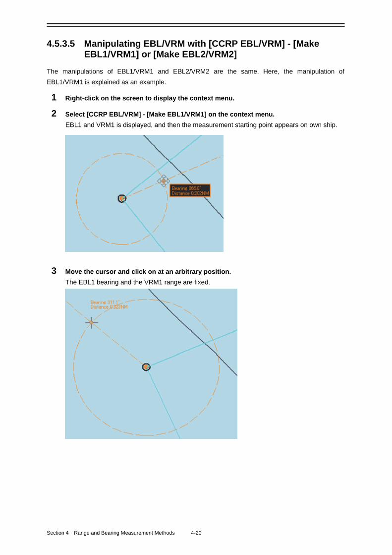
Section 4 Range and Bearing Measurement Methods 4-20
4.5.3.5 Manipulating EBL/VRM with [CCRP EBL/VRM] - [Make EBL1/VRM1] or [Make EBL2/VRM2]
The manipulations of EBL1/VRM1 and EBL2/VRM2 are the same. Here, the manipulation of
EBL1/VRM1 is explained as an example.
1 Right-click on the screen to display the context menu.
2 Select [CCRP EBL/VRM] - [Make EBL1/VRM1] on the context menu.
EBL1 and VRM1 is displayed, and then the measurement starting point appears on own ship.
3 Move the cursor and click on at an arbitrary position.
The EBL1 bearing and the VRM1 range are fixed.
4-21 Section 4 Range and Bearing Measurement Methods
1
2
3
4
5
6
7
8
9
10
11
12
13
14
15
16
17
18
19
20
21
22
23
24
25
APP A
APP B
1
4.5.3.6 Manipulating EBL with [CCRP EBL/VRM] - [Make EBL1] or [Make EBL2]
The manipulations of EBL1 and EBL2 are the same. Here, the manipulation of EBL1 is explained as an
example.
1 Right-click on the screen to display the context menu.
2 Select [CCRP EBL/VRM] - [Make EBL1] on the context menu.
EBL1 is displayed, and then the measurement starting point appears on own ship.
3 Move the cursor and click on at an arbitrary position.
The EBL1 bearing is fixed.
4.5.3.7 Manipulating VRM with [CCRP EBL/VRM] - [Make VRM1] or [Make VRM2]
The manipulations of VRM1 and VRM2 are the same. Here, the manipulation of VRM1 is explained as
an example.
1 Right-click on the screen to display the context menu.
2 Select [CCRP EBL/VRM] - [Make VRM1] on the context menu.
VRM1 is displayed, and then the measurement starting point appears on own ship.
3 Move the cursor and click on at an arbitrary position.
The VRM1 range is fixed.
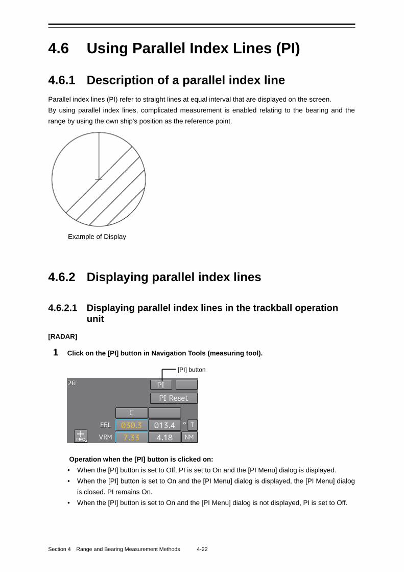
Section 4 Range and Bearing Measurement Methods 4-22
4.6 Using Parallel Index Lines (PI)
4.6.1 Description of a parallel index line
Parallel index lines (PI) refer to straight lines at equal interval that are displayed on the screen.
By using parallel index lines, complicated measurement is enabled relating to the bearing and the
range by using the own ship's position as the reference point.
4.6.2 Displaying parallel index lines
4.6.2.1 Displaying parallel index lines in the trackball operation unit
[RADAR]
1 Click on the [PI] button in Navigation Tools (measuring tool).
Operation when the [PI] button is clicked on:
• When the [PI] button is set to Off, PI is set to On and the [PI Menu] dialog is displayed.
• When the [PI] button is set to On and the [PI Menu] dialog is displayed, the [PI Menu] dialog
is closed. PI remains On.
• When the [PI] button is set to On and the [PI Menu] dialog is not displayed, PI is set to Off.
[PI] button
Example of Display
4-23 Section 4 Range and Bearing Measurement Methods
1
2
3
4
5
6
7
8
9
10
11
12
13
14
15
16
17
18
19
20
21
22
23
24
25
APP A
APP B
1
Memo
The [PI Menu] dialog can also be displayed by clicking on [Tool] - [PI] on the menu.
2 Set PI on the [PI Menu] dialog.
For the details of the [PI Menu] dialog, refer to "4.6.2.3 "Description of the [PI Menu] dialog".
The [PI Menu] dialog setting method varies depending on the PI operation mode. For the details,
refer to the descriptions of the operation mode in "4.6.3 Setting all the parallel index lines
concurrently (All mode)", "4.6.4 Setting parallel index lines individually (Individual mode)", "4.6.5
Displaying lines at equal interval on the left and right sides of the own ship's position (Track
mode)", and "4.6.6 Displaying two intersecting lines (Equiangular mode)".
[ECDIS]
1 Click on the [Menu] button on the left toolbar.
The menu is displayed.
2 Click on [Tools] - [PI].
The [PI Menu] dialog box appears.
To clear parallel index lines:
1 Set the [Display for All Lines] button to Off by clicking on it.
The parallel index lines disappear.
4.6.2.2 Displaying parallel index lines in the keyboard operation unit
1 Press the [PI] key.
Operation when the [PI] key is pressed:
- When the [Display for All Lines] button is set to Off, PI is set to On and the [PI Menu] dialog
box is displayed.
- When the [Display for All Lines] button is set to On and the [PI Menu] dialog is displayed, the
[PI Menu] dialog is closed. PI remains On.
- When the [Display for All Lines] button is set to On and the [PI Menu] dialog is not displayed,
PI is set to Off.
2 Set PI on the [PI Menu] dialog.
For the [PI Menu] dialog, refer to "4.6.2.3 Description of the [PI Menu] dialog".
The [PI Menu] dialog setting method varies according to the PI operation mode. For the details,
refer to the description of each operation mode, "4.6.3 Setting all the parallel index lines
concurrently (All mode)", "4.6.4 Setting parallel index lines individually (Individual mode)", "4.6.5
Displaying lines at equal interval on the left and right sides of the own ship's position (Track
mode)", and "4.6.6 Displaying two intersecting lines (Equiangular mode)".
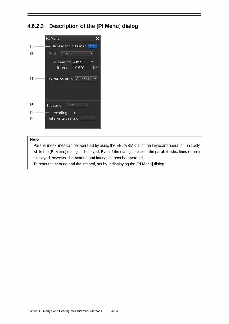
Section 4 Range and Bearing Measurement Methods 4-24
4.6.2.3 Description of the [PI Menu] dialog
Note
Parallel index lines can be operated by using the EBL/VRM dial of the keyboard operation unit only
while the [PI Menu] dialog is displayed. Even if the dialog is closed, the parallel index lines remain
displayed, however, the bearing and interval cannot be operated.
To reset the bearing and the interval, set by redisplaying the [PI Menu] dialog.
[1]
[2]
[3]
[4]
[5] [6]
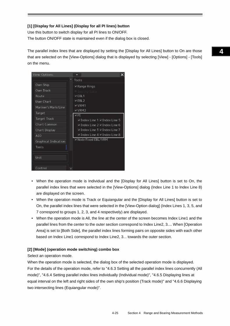
4-25 Section 4 Range and Bearing Measurement Methods
1
2
3
4
5
6
7
8
9
10
11
12
13
14
15
16
17
18
19
20
21
22
23
24
25
APP A
APP B
1
[1] [Display for All Lines] (Display for all PI lines) button
Use this button to switch display for all PI lines to ON/OFF.
The button ON/OFF state is maintained even if the dialog box is closed.
The parallel index lines that are displayed by setting the [Display for All Lines] button to On are those
that are selected on the [View-Options] dialog that is displayed by selecting [View] - [Options] - [Tools]
on the menu.
• When the operation mode is Individual and the [Display for All Lines] button is set to On, the
parallel index lines that were selected in the [View-Options] dialog (Index Line 1 to Index Line 8)
are displayed on the screen.
• When the operation mode is Track or Equiangular and the [Display for All Lines] button is set to
On, the parallel index lines that were selected in the [View-Option dialog] (Index Lines 1, 3, 5, and
7 correspond to groups 1, 2, 3, and 4 respectively) are displayed.
• When the operation mode is All, the line at the center of the screen becomes Index Line1 and the
parallel lines from the center to the outer section correspond to Index Line2, 3.... When [Operation
Area] is set to [Both Side], the parallel index lines forming pairs on opposite sides with each other
based on Index Line1 correspond to Index Line2, 3... towards the outer section.
[2] [Mode] (operation mode switching) combo box
Select an operation mode.
When the operation mode is selected, the dialog box of the selected operation mode is displayed.
For the details of the operation mode, refer to "4.6.3 Setting all the parallel index lines concurrently (All
mode)", "4.6.4 Setting parallel index lines individually (Individual mode)", "4.6.5 Displaying lines at
equal interval on the left and right sides of the own ship's position (Track mode)" and "4.6.6 Displaying
two intersecting lines (Equiangular mode)".
Section 4 Range and Bearing Measurement Methods 4-26
[3] Parameter setting area by operation mode
Set parameters in each operation mode.
The settings differ depending on the operating mode.
Refer to "4.6.3 Setting all the parallel index lines concurrently (All mode)", "4.6.4 Setting parallel index
lines individually (Individual mode)", "4.6.5 Displaying lines at equal interval on the left and right sides
of the own ship's position (Track mode)" and "4.6.6 Displaying two intersecting lines (Equiangular
mode)".
[4] [Floating] combo box
Move the center of the parallel index line.
Select the Floating mode from the list.
• [Off]: Sets the starting point of the parallel index line to the CCRP position.
• [Screen Fix]: Moves the center of the parallel index line and fixes it on the screen.
• [L/L Fix]: Moves the center of the parallel index line and fixes it based on the latitude and
longitude.
(Connection of a navigation unit is required.)
[5] [Heading Link] (Heading link setting)
Set whether the parallel index line is linked to the ship's heading.
• When this item is checked, the parallel index line is linked to the ship's heading.
• When this item is unchecked, the parallel index line is not linked to the ship's heading.
Different values can be set for the angle of the parallel index lines when this item is checked and the
angle of the parallel index lines when the item is unchecked.
[6] [Reference Bearing] (Reference bearing selection) combo box
Set a reference bearing of the bearing value display of the parallel index line.
• [True]: Displays in true bearing (based on the North).
• [HL]: Displays in the heading line reference.
• Index Line 1 to Index Line 8: Displays by using the Index Line as the reference. (Only when
the operation mode is [Individual])
• Group 1 to Group 4: Displays by using the Group as the reference. (Only when the operation
mode is [Track])
Memo
[Reference Bearing] (reference bearing selection) is not displayed in [Equiangular] mode as the
operation mode.
4-27 Section 4 Range and Bearing Measurement Methods
1
2
3
4
5
6
7
8
9
10
11
12
13
14
15
16
17
18
19
20
21
22
23
24
25
APP A
APP B
1
Switching the Floating mode When [Screen Fix] or [L/L Fix] is selected in switching the Floating mode, the cursor mode changes.
Note
When the operation mode is [All] and the reference point that is set in [L/L Fix] moves to the
position outside of the PPI circle, the floating mode is set to Off and the own ship's position
becomes the reference point.
• When the screen is clicked on, the fixed position or the coordinates on the screen are determined,
and the cursor is changed to the normal cursor.
• When [Screen Fix] or [L/L Fix] is re-selected after the determination, the cursor changes to the
center selection cursor for parallel index lines.
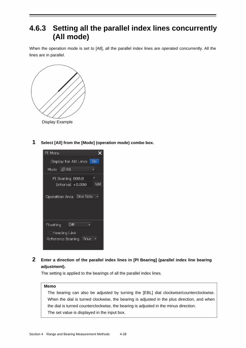
Section 4 Range and Bearing Measurement Methods 4-28
4.6.3 Setting all the parallel index lines concurrently (All mode)
When the operation mode is set to [All], all the parallel index lines are operated concurrently. All the
lines are in parallel.
1 Select [All] from the [Mode] (operation mode) combo box.
2 Enter a direction of the parallel index lines in [PI Bearing] (parallel index line bearing
adjustment).
The setting is applied to the bearings of all the parallel index lines.
Memo
The bearing can also be adjusted by turning the [EBL] dial clockwise/counterclockwise.
When the dial is turned clockwise, the bearing is adjusted in the plus direction, and when
the dial is turned counterclockwise, the bearing is adjusted in the minus direction.
The set value is displayed in the input box.
Display Example
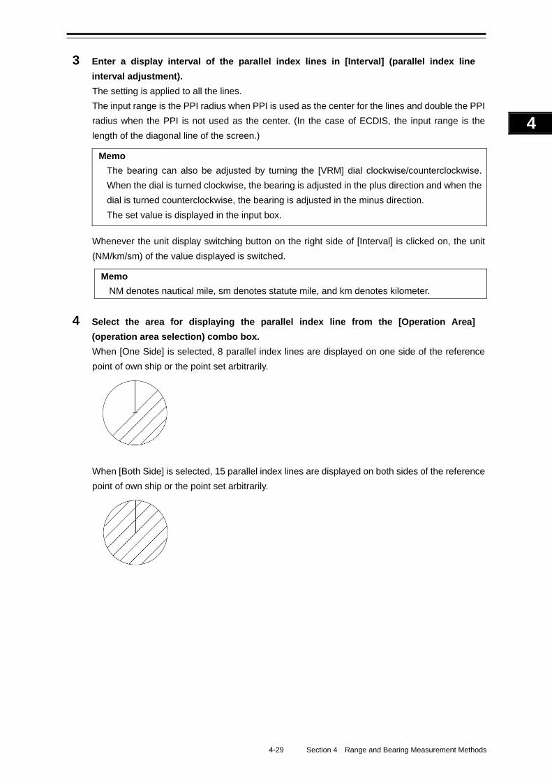
4-29 Section 4 Range and Bearing Measurement Methods
1
2
3
4
5
6
7
8
9
10
11
12
13
14
15
16
17
18
19
20
21
22
23
24
25
APP A
APP B
1
3 Enter a display interval of the parallel index lines in [Interval] (parallel index line
interval adjustment).
The setting is applied to all the lines.
The input range is the PPI radius when PPI is used as the center for the lines and double the PPI
radius when the PPI is not used as the center. (In the case of ECDIS, the input range is the
length of the diagonal line of the screen.)
Memo
The bearing can also be adjusted by turning the [VRM] dial clockwise/counterclockwise.
When the dial is turned clockwise, the bearing is adjusted in the plus direction and when the
dial is turned counterclockwise, the bearing is adjusted in the minus direction.
The set value is displayed in the input box.
Whenever the unit display switching button on the right side of [Interval] is clicked on, the unit
(NM/km/sm) of the value displayed is switched.
Memo
NM denotes nautical mile, sm denotes statute mile, and km denotes kilometer.
4 Select the area for displaying the parallel index line from the [Operation Area]
(operation area selection) combo box.
When [One Side] is selected, 8 parallel index lines are displayed on one side of the reference
point of own ship or the point set arbitrarily.
When [Both Side] is selected, 15 parallel index lines are displayed on both sides of the reference
point of own ship or the point set arbitrarily.
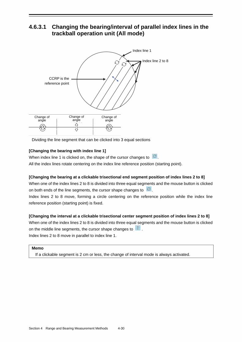
Section 4 Range and Bearing Measurement Methods 4-30
4.6.3.1 Changing the bearing/interval of parallel index lines in the trackball operation unit (All mode)
[Changing the bearing with index line 1]
When index line 1 is clicked on, the shape of the cursor changes to .
All the index lines rotate centering on the index line reference position (starting point).
[Changing the bearing at a clickable trisectional end segment position of index lines 2 to 8]
When one of the index lines 2 to 8 is divided into three equal segments and the mouse button is clicked
on both ends of the line segments, the cursor shape changes to .
Index lines 2 to 8 move, forming a circle centering on the reference position while the index line
reference position (starting point) is fixed.
[Changing the interval at a clickable trisectional center segment position of index lines 2 to 8]
When one of the index lines 2 to 8 is divided into three equal segments and the mouse button is clicked
on the middle line segments, the cursor shape changes to .
Index lines 2 to 8 move in parallel to index line 1.
Memo
If a clickable segment is 2 cm or less, the change of interval mode is always activated.
Change of angle
Change of angle
Change of angle
Dividing the line segment that can be clicked into 3 equal sections
CCRP is the reference point
Index line 1
Index line 2 to 8
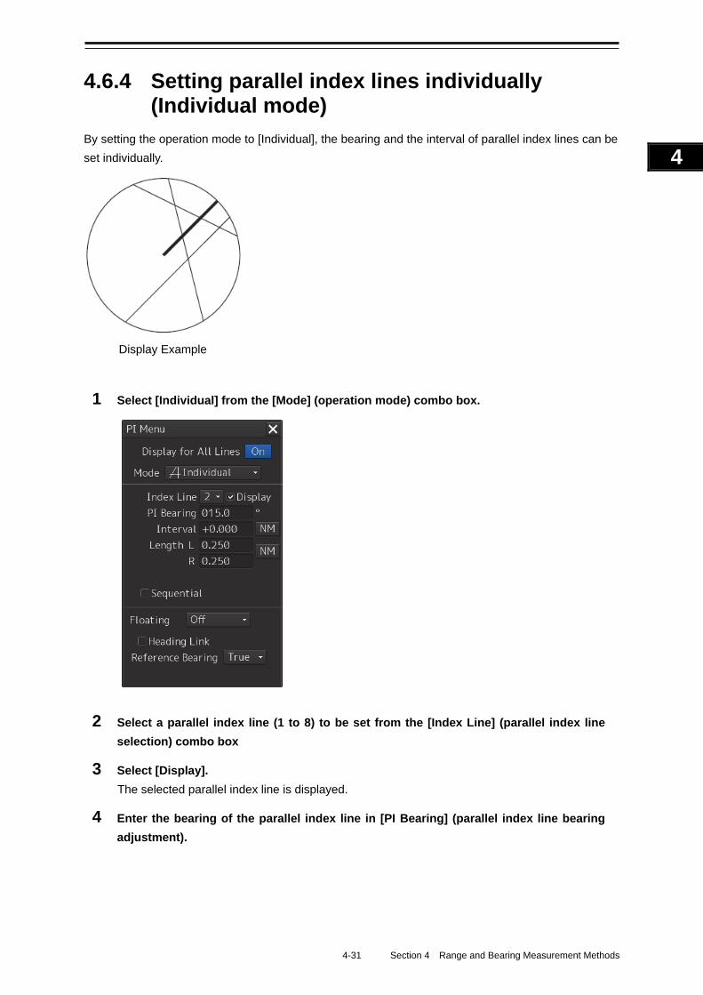
4-31 Section 4 Range and Bearing Measurement Methods
1
2
3
4
5
6
7
8
9
10
11
12
13
14
15
16
17
18
19
20
21
22
23
24
25
APP A
APP B
1
4.6.4 Setting parallel index lines individually (Individual mode)
By setting the operation mode to [Individual], the bearing and the interval of parallel index lines can be
set individually.
1 Select [Individual] from the [Mode] (operation mode) combo box.
2 Select a parallel index line (1 to 8) to be set from the [Index Line] (parallel index line
selection) combo box
3 Select [Display].
The selected parallel index line is displayed.
4 Enter the bearing of the parallel index line in [PI Bearing] (parallel index line bearing
adjustment).
Display Example
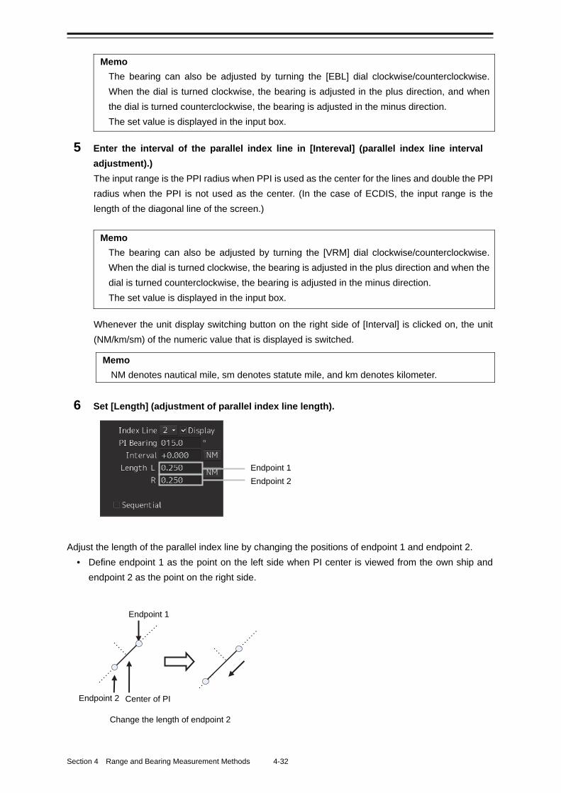
Section 4 Range and Bearing Measurement Methods 4-32
Memo
The bearing can also be adjusted by turning the [EBL] dial clockwise/counterclockwise.
When the dial is turned clockwise, the bearing is adjusted in the plus direction, and when
the dial is turned counterclockwise, the bearing is adjusted in the minus direction.
The set value is displayed in the input box.
5 Enter the interval of the parallel index line in [Intereval] (parallel index line interval
adjustment).)
The input range is the PPI radius when PPI is used as the center for the lines and double the PPI
radius when the PPI is not used as the center. (In the case of ECDIS, the input range is the
length of the diagonal line of the screen.)
Memo
The bearing can also be adjusted by turning the [VRM] dial clockwise/counterclockwise.
When the dial is turned clockwise, the bearing is adjusted in the plus direction and when the
dial is turned counterclockwise, the bearing is adjusted in the minus direction.
The set value is displayed in the input box.
Whenever the unit display switching button on the right side of [Interval] is clicked on, the unit
(NM/km/sm) of the numeric value that is displayed is switched.
Memo
NM denotes nautical mile, sm denotes statute mile, and km denotes kilometer.
6 Set [Length] (adjustment of parallel index line length).
Adjust the length of the parallel index line by changing the positions of endpoint 1 and endpoint 2.
• Define endpoint 1 as the point on the left side when PI center is viewed from the own ship and
endpoint 2 as the point on the right side.
Endpoint 2
Endpoint 1
Change the length of endpoint 2
Center of PI
Endpoint 2 Endpoint 1
4-33 Section 4 Range and Bearing Measurement Methods
1
2
3
4
5
6
7
8
9
10
11
12
13
14
15
16
17
18
19
20
21
22
23
24
25
APP A
APP B
1
• Set the mode to the endpoint change mode by pressing the [VRM] dial and turn the [VRM] dial to
change the position of an endpoint.
Clockwise: + (Direction from the center of PI to outside)
Counterclockwise: - (Direction towards the center of PI)
The input range is as follows.
• The minimum length of a parallel index line from the left end to the right end is 2 cm.
• The maximum length is double the PPI radius.
Memo
A negative value can also be set for [Length].
• In the case of the left end, the left direction from the center becomes a positive value and the
right direction from the center becomes a negative value.
• In the case of the right end, the right direction from the center becomes a positive value and the
left direction from the center becomes a negative value.
Whenever the unit display switching button on the right side of [length] is clicked on, the unit
(NM/km/sm) of the numeric value that is displayed is switched.
Memo
NM denotes nautical mile, sm denotes statute mile, and km denotes kilometer.
Setting parallel index lines consecutively When [Sequential] is checked and [Screen Fix] or [L/L Fix] is selected at floating mode switching, the
parallel index lines to be set are changed in the sequence of Index Line12•••81••• and setting
can be performed consecutively.
Note
The index lines that are set to be hidden by selecting [View] - [Options] - [Tools] on the menu are
skipped during operation.
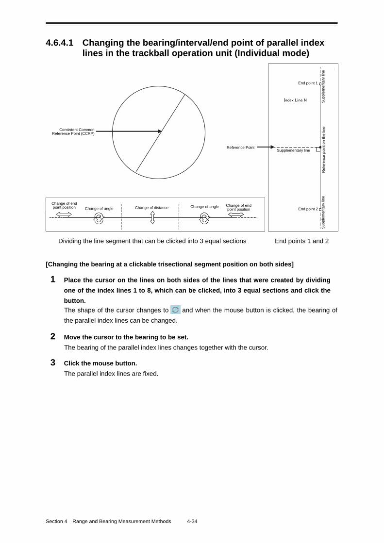
Section 4 Range and Bearing Measurement Methods 4-34
4.6.4.1 Changing the bearing/interval/end point of parallel index lines in the trackball operation unit (Individual mode)
[Changing the bearing at a clickable trisectional segment position on both sides]
1 Place the cursor on the lines on both sides of the lines that were created by dividing
one of the index lines 1 to 8, which can be clicked, into 3 equal sections and click the
button.
The shape of the cursor changes to and when the mouse button is clicked, the bearing of
the parallel index lines can be changed.
2 Move the cursor to the bearing to be set.
The bearing of the parallel index lines changes together with the cursor.
3 Click the mouse button.
The parallel index lines are fixed.
Reference Point
Consistent Common Reference Point (CCRP)
End point 1
Su
pp
lem
en
tary
lin
e R
efe
ren
ce p
oin
t on
the
line
Su
pp
lem
en
tary
lin
e
Supplementary line
End point 2
Change of end point position Change of angle Change of distance Change of angle Change of end
point position
Dividing the line segment that can be clicked into 3 equal sections End points 1 and 2
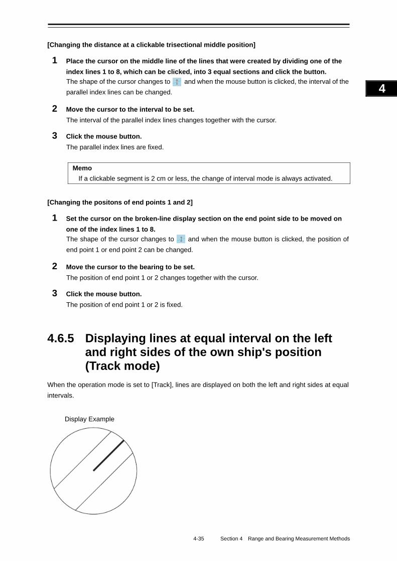
4-35 Section 4 Range and Bearing Measurement Methods
1
2
3
4
5
6
7
8
9
10
11
12
13
14
15
16
17
18
19
20
21
22
23
24
25
APP A
APP B
1
[Changing the distance at a clickable trisectional middle position]
1 Place the cursor on the middle line of the lines that were created by dividing one of the
index lines 1 to 8, which can be clicked, into 3 equal sections and click the button.
The shape of the cursor changes to and when the mouse button is clicked, the interval of the
parallel index lines can be changed.
2 Move the cursor to the interval to be set.
The interval of the parallel index lines changes together with the cursor.
3 Click the mouse button.
The parallel index lines are fixed.
Memo
If a clickable segment is 2 cm or less, the change of interval mode is always activated.
[Changing the positons of end points 1 and 2]
1 Set the cursor on the broken-line display section on the end point side to be moved on
one of the index lines 1 to 8.
The shape of the cursor changes to and when the mouse button is clicked, the position of
end point 1 or end point 2 can be changed.
2 Move the cursor to the bearing to be set.
The position of end point 1 or 2 changes together with the cursor.
3 Click the mouse button.
The position of end point 1 or 2 is fixed.
4.6.5 Displaying lines at equal interval on the left and right sides of the own ship's position (Track mode)
When the operation mode is set to [Track], lines are displayed on both the left and right sides at equal
intervals.
Display Example
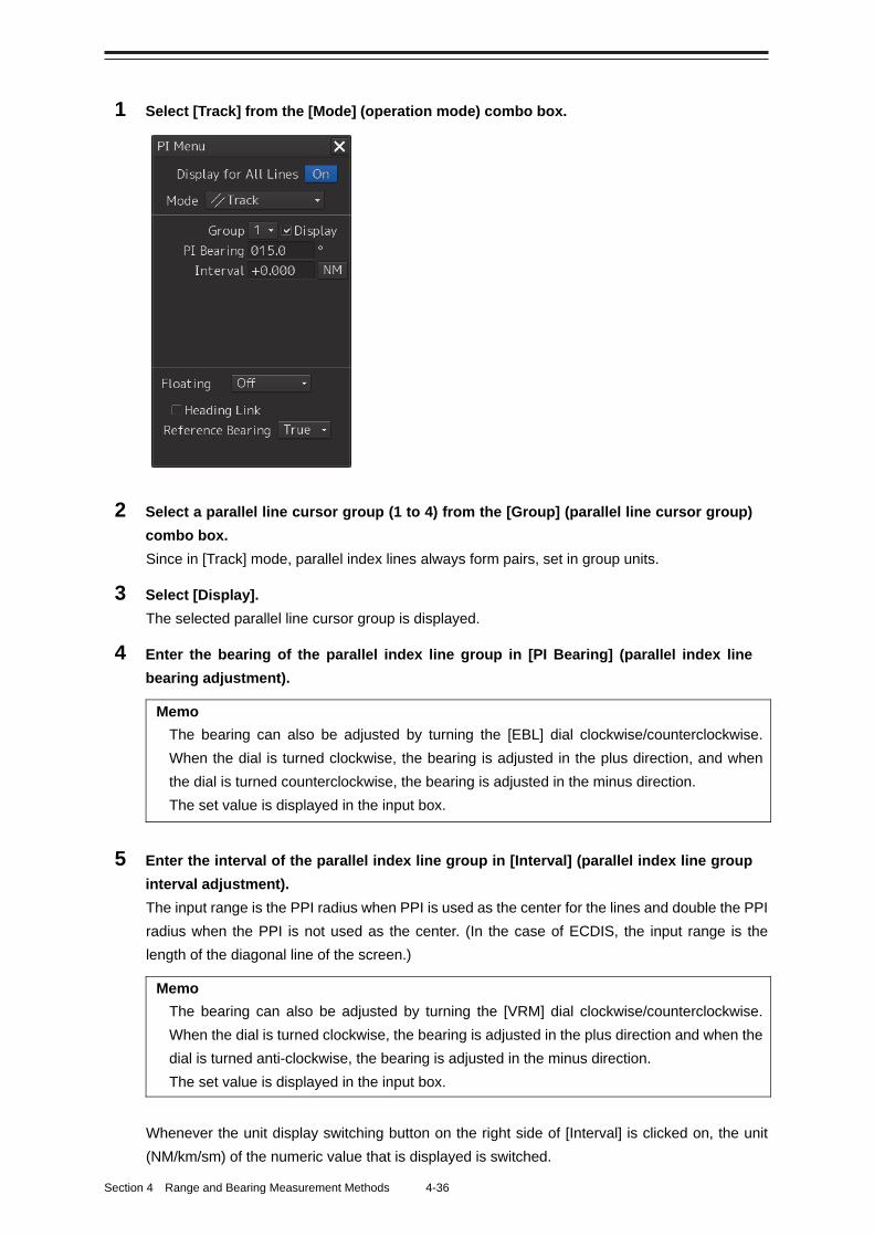
Section 4 Range and Bearing Measurement Methods 4-36
1 Select [Track] from the [Mode] (operation mode) combo box.
2 Select a parallel line cursor group (1 to 4) from the [Group] (parallel line cursor group)
combo box.
Since in [Track] mode, parallel index lines always form pairs, set in group units.
3 Select [Display].
The selected parallel line cursor group is displayed.
4 Enter the bearing of the parallel index line group in [PI Bearing] (parallel index line
bearing adjustment).
Memo
The bearing can also be adjusted by turning the [EBL] dial clockwise/counterclockwise.
When the dial is turned clockwise, the bearing is adjusted in the plus direction, and when
the dial is turned counterclockwise, the bearing is adjusted in the minus direction.
The set value is displayed in the input box.
5 Enter the interval of the parallel index line group in [Interval] (parallel index line group
interval adjustment).
The input range is the PPI radius when PPI is used as the center for the lines and double the PPI
radius when the PPI is not used as the center. (In the case of ECDIS, the input range is the
length of the diagonal line of the screen.)
Memo
The bearing can also be adjusted by turning the [VRM] dial clockwise/counterclockwise.
When the dial is turned clockwise, the bearing is adjusted in the plus direction and when the
dial is turned anti-clockwise, the bearing is adjusted in the minus direction.
The set value is displayed in the input box.
Whenever the unit display switching button on the right side of [Interval] is clicked on, the unit
(NM/km/sm) of the numeric value that is displayed is switched.
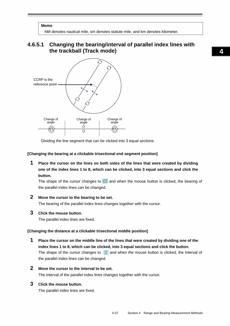
4-37 Section 4 Range and Bearing Measurement Methods
1
2
3
4
5
6
7
8
9
10
11
12
13
14
15
16
17
18
19
20
21
22
23
24
25
APP A
APP B
1
Memo
NM denotes nautical mile, sm denotes statute mile, and km denotes kilometer.
4.6.5.1 Changing the bearing/interval of parallel index lines with the trackball (Track mode)
[Changing the bearing at a clickable trisectional end segment position]
1 Place the cursor on the lines on both sides of the lines that were created by dividing
one of the index lines 1 to 8, which can be clicked, into 3 equal sections and click the
button.
The shape of the cursor changes to and when the mouse button is clicked, the bearing of
the parallel index lines can be changed.
2 Move the cursor to the bearing to be set.
The bearing of the parallel index lines changes together with the cursor.
3 Click the mouse button.
The parallel index lines are fixed.
[Changing the distance at a clickable trisectional middle position]
1 Place the cursor on the middle line of the lines that were created by dividing one of the
index lines 1 to 8, which can be clicked, into 3 equal sections and click the button.
The shape of the cursor changes to and when the mouse button is clicked, the interval of
the parallel index lines can be changed.
2 Move the cursor to the interval to be set.
The interval of the parallel index lines changes together with the cursor.
3 Click the mouse button.
The parallel index lines are fixed.
Change of angle
Change of angle
Change of angle
Dividing the line segment that can be clicked into 3 equal sections
CCRP is the reference point
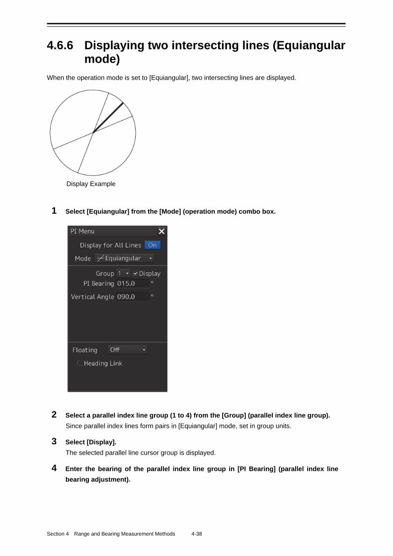
Section 4 Range and Bearing Measurement Methods 4-38
4.6.6 Displaying two intersecting lines (Equiangular mode)
When the operation mode is set to [Equiangular], two intersecting lines are displayed.
1 Select [Equiangular] from the [Mode] (operation mode) combo box.
2 Select a parallel index line group (1 to 4) from the [Group] (parallel index line group).
Since parallel index lines form pairs in [Equiangular] mode, set in group units.
3 Select [Display].
The selected parallel line cursor group is displayed.
4 Enter the bearing of the parallel index line group in [PI Bearing] (parallel index line
bearing adjustment).
Display Example
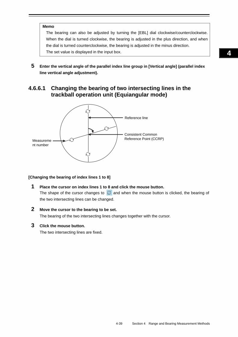
4-39 Section 4 Range and Bearing Measurement Methods
1
2
3
4
5
6
7
8
9
10
11
12
13
14
15
16
17
18
19
20
21
22
23
24
25
APP A
APP B
1
Memo
The bearing can also be adjusted by turning the [EBL] dial clockwise/counterclockwise.
When the dial is turned clockwise, the bearing is adjusted in the plus direction, and when
the dial is turned counterclockwise, the bearing is adjusted in the minus direction.
The set value is displayed in the input box.
5 Enter the vertical angle of the parallel index line group in [Vertical angle] (parallel index
line vertical angle adjustment).
4.6.6.1 Changing the bearing of two intersecting lines in the trackball operation unit (Equiangular mode)
[Changing the bearing of index lines 1 to 8]
1 Place the cursor on index lines 1 to 8 and click the mouse button.
The shape of the cursor changes to and when the mouse button is clicked, the bearing of
the two intersecting lines can be changed.
2 Move the cursor to the bearing to be set.
The bearing of the two intersecting lines changes together with the cursor.
3 Click the mouse button.
The two intersecting lines are fixed.
Consistent Common Reference Point (CCRP) Measureme
nt number
Reference line
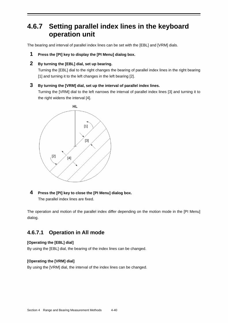
Section 4 Range and Bearing Measurement Methods 4-40
4.6.7 Setting parallel index lines in the keyboard operation unit
The bearing and interval of parallel index lines can be set with the [EBL] and [VRM] dials.
1 Press the [PI] key to display the [PI Menu] dialog box.
2 By turning the [EBL] dial, set up bearing.
Turning the [EBL] dial to the right changes the bearing of parallel index lines in the right bearing
[1] and turning it to the left changes in the left bearing [2].
3 By turning the [VRM] dial, set up the interval of parallel index lines.
Turning the [VRM] dial to the left narrows the interval of parallel index lines [3] and turning it to
the right widens the interval [4].
4 Press the [PI] key to close the [PI Menu] dialog box.
The parallel index lines are fixed.
The operation and motion of the parallel index differ depending on the motion mode in the [PI Menu]
dialog.
4.6.7.1 Operation in All mode
[Operating the [EBL] dial]
By using the [EBL] dial, the bearing of the index lines can be changed.
[Operating the [VRM] dial]
By using the [VRM] dial, the interval of the index lines can be changed.
[1]
[2]
[3]
[4]
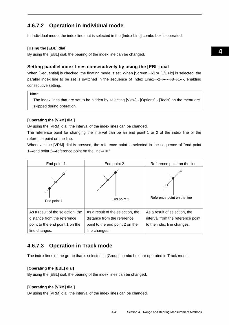
4-41 Section 4 Range and Bearing Measurement Methods
1
2
3
4
5
6
7
8
9
10
11
12
13
14
15
16
17
18
19
20
21
22
23
24
25
APP A
APP B
1
4.6.7.2 Operation in Individual mode
In Individual mode, the index line that is selected in the [Index Line] combo box is operated.
[Using the [EBL] dial]
By using the [EBL] dial, the bearing of the index line can be changed.
Setting parallel index lines consecutively by using the [EBL] dial When [Sequential] is checked, the floating mode is set. When [Screen Fix] or [L/L Fix] is selected, the
parallel index line to be set is switched in the sequence of Index Line12•••81•••, enabling
consecutive setting.
Note
The index lines that are set to be hidden by selecting [View] - [Options] - [Tools] on the menu are
skipped during operation.
[Operating the [VRM] dial]
By using the [VRM] dial, the interval of the index lines can be changed.
The reference point for changing the interval can be an end point 1 or 2 of the index line or the
reference point on the line.
Whenever the [VRM] dial is pressed, the reference point is selected in the sequence of "end point
1end point 2reference point on the line•••"
End point 1 End point 2 Reference point on the line
As a result of the selection, the
distance from the reference
point to the end point 1 on the
line changes.
As a result of the selection, the
distance from the reference
point to the end point 2 on the
line changes.
As a result of selection, the
interval from the reference point
to the index line changes.
4.6.7.3 Operation in Track mode
The index lines of the group that is selected in [Group] combo box are operated in Track mode.
[Operating the [EBL] dial]
By using the [EBL] dial, the bearing of the index lines can be changed.
[Operating the [VRM] dial]
By using the [VRM] dial, the interval of the index lines can be changed.
Reference point on the line End point 2 End point 1
Section 4 Range and Bearing Measurement Methods 4-42
4.6.7.4 Operation in Equiangular mode
The index lines of the group that is selected in [Group] combo box are operated in Equiangular mode.
[Operating the [EBL] dial]
By pressing the [EBL] dial, the "Group reference line (PI Bearing)" and the "Group measurement line"
can be set.
Whenever the [EBL] dial is pressed, the "Group reference line (PI Bearing)" and the "Group
measurement line" are selected alternately.
Memo
A measurement line can be set across the reference line. (When a measurement line is set across
the reference line by rotating the dial in the minus direction, the measured bearing data changes
as 0°359.9°.)
When the reference line is set by using the EBL dial, the value of the measured bearing data is
maintained and the measurement line follows concurrently.
[Operation the [VRM] dial]
In Equiangular mode, the [VRM] dial is disabled.
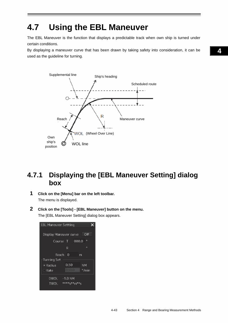
4-43 Section 4 Range and Bearing Measurement Methods
1
2
3
4
5
6
7
8
9
10
11
12
13
14
15
16
17
18
19
20
21
22
23
24
25
APP A
APP B
1
4.7 Using the EBL Maneuver The EBL Maneuver is the function that displays a predictable track when own ship is turned under
certain conditions.
By displaying a maneuver curve that has been drawn by taking safety into consideration, it can be
used as the guideline for turning.
4.7.1 Displaying the [EBL Maneuver Setting] dialog box
1 Click on the [Menu] bar on the left toolbar.
The menu is displayed.
2 Click on the [Tools] - [EBL Maneuver] button on the menu.
The [EBL Maneuver Setting] dialog box appears.
Supplemental line Ship's heading
Scheduled route
Own ship's
position
Reach Maneuver curve
(Wheel Over Line)
WOL line
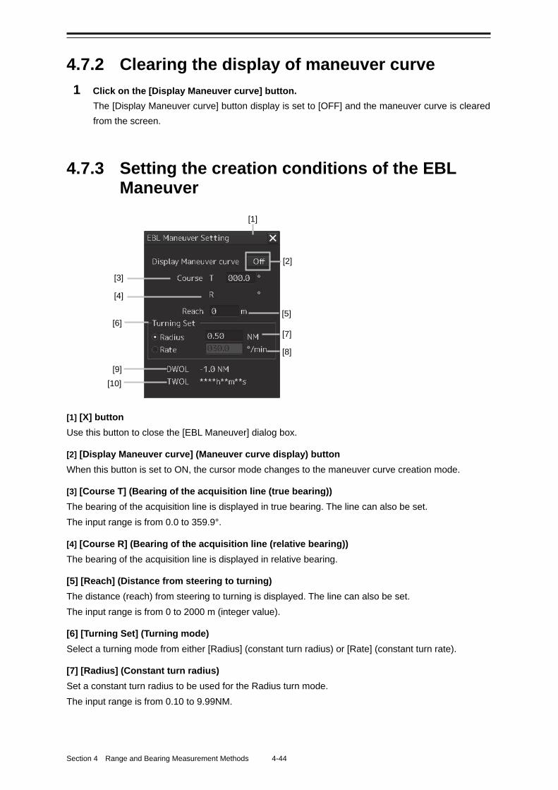
Section 4 Range and Bearing Measurement Methods 4-44
4.7.2 Clearing the display of maneuver curve
1 Click on the [Display Maneuver curve] button.
The [Display Maneuver curve] button display is set to [OFF] and the maneuver curve is cleared
from the screen.
4.7.3 Setting the creation conditions of the EBL Maneuver
[1] [X] button
Use this button to close the [EBL Maneuver] dialog box.
[2] [Display Maneuver curve] (Maneuver curve display) button
When this button is set to ON, the cursor mode changes to the maneuver curve creation mode.
[3] [Course T] (Bearing of the acquisition line (true bearing))
The bearing of the acquisition line is displayed in true bearing. The line can also be set.
The input range is from 0.0 to 359.9°.
[4] [Course R] (Bearing of the acquisition line (relative bearing))
The bearing of the acquisition line is displayed in relative bearing.
[5] [Reach] (Distance from steering to turning)
The distance (reach) from steering to turning is displayed. The line can also be set.
The input range is from 0 to 2000 m (integer value).
[6] [Turning Set] (Turning mode)
Select a turning mode from either [Radius] (constant turn radius) or [Rate] (constant turn rate).
[7] [Radius] (Constant turn radius)
Set a constant turn radius to be used for the Radius turn mode.
The input range is from 0.10 to 9.99NM.
[2]
[7] [8]
[4]
[6]
[10] [9]
[5]
[1]
[3]
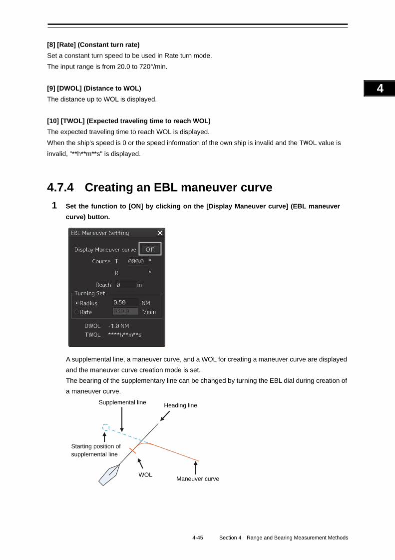
4-45 Section 4 Range and Bearing Measurement Methods
1
2
3
4
5
6
7
8
9
10
11
12
13
14
15
16
17
18
19
20
21
22
23
24
25
APP A
APP B
1
[8] [Rate] (Constant turn rate)
Set a constant turn speed to be used in Rate turn mode.
The input range is from 20.0 to 720°/min.
[9] [DWOL] (Distance to WOL)
The distance up to WOL is displayed.
[10] [TWOL] (Expected traveling time to reach WOL)
The expected traveling time to reach WOL is displayed.
When the ship's speed is 0 or the speed information of the own ship is invalid and the TWOL value is
invalid, "**h**m**s" is displayed.
4.7.4 Creating an EBL maneuver curve
1 Set the function to [ON] by clicking on the [Display Maneuver curve] (EBL maneuver
curve) button.
A supplemental line, a maneuver curve, and a WOL for creating a maneuver curve are displayed
and the maneuver curve creation mode is set.
The bearing of the supplementary line can be changed by turning the EBL dial during creation of
a maneuver curve.
Supplemental line Heading line
WOL Maneuver curve
Starting position of supplemental line
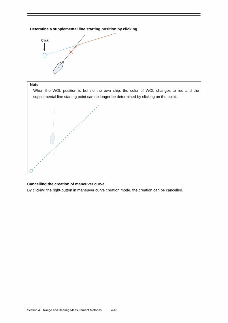
Section 4 Range and Bearing Measurement Methods 4-46
Determine a supplemental line starting position by clicking.
Note
When the WOL position is behind the own ship, the color of WOL changes to red and the
supplemental line starting point can no longer be determined by clicking on the point.
Cancelling the creation of maneuver curve
By clicking the right-button in maneuver curve creation mode, the creation can be cancelled.
Click
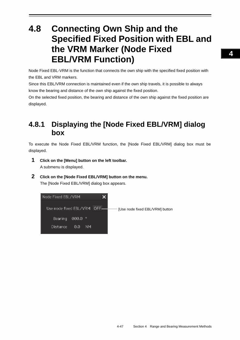
4-47 Section 4 Range and Bearing Measurement Methods
1
2
3
4
5
6
7
8
9
10
11
12
13
14
15
16
17
18
19
20
21
22
23
24
25
APP A
APP B
1
4.8 Connecting Own Ship and the Specified Fixed Position with EBL and the VRM Marker (Node Fixed EBL/VRM Function)
Node Fixed EBL-VRM is the function that connects the own ship with the specified fixed position with
the EBL and VRM markers.
Since this EBL/VRM connection is maintained even if the own ship travels, it is possible to always
know the bearing and distance of the own ship against the fixed position.
On the selected fixed position, the bearing and distance of the own ship against the fixed position are
displayed.
4.8.1 Displaying the [Node Fixed EBL/VRM] dialog box
To execute the Node Fixed EBL/VRM function, the [Node Fixed EBL/VRM] dialog box must be
displayed.
1 Click on the [Menu] button on the left toolbar.
A submenu is displayed.
2 Click on the [Node Fixed EBL/VRM] button on the menu.
The [Node Fixed EBL/VRM] dialog box appears.
[Use node fixed EBL/VRM] button
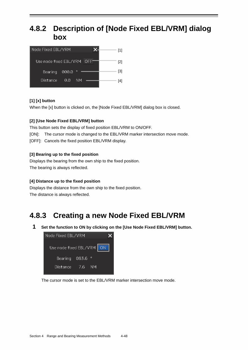
Section 4 Range and Bearing Measurement Methods 4-48
4.8.2 Description of [Node Fixed EBL/VRM] dialog box
[1] [x] button
When the [x] button is clicked on, the [Node Fixed EBL/VRM] dialog box is closed.
[2] [Use Node Fixed EBL/VRM] button
This button sets the display of fixed position EBL/VRM to ON/OFF.
[ON]: The cursor mode is changed to the EBL/VRM marker intersection move mode.
[OFF]: Cancels the fixed position EBL/VRM display.
[3] Bearing up to the fixed position
Displays the bearing from the own ship to the fixed position.
The bearing is always reflected.
[4] Distance up to the fixed position
Displays the distance from the own ship to the fixed position.
The distance is always reflected.
4.8.3 Creating a new Node Fixed EBL/VRM
1 Set the function to ON by clicking on the [Use Node Fixed EBL/VRM] button.
The cursor mode is set to the EBL/VRM marker intersection move mode.
[1]
[2]
[4]
[3]
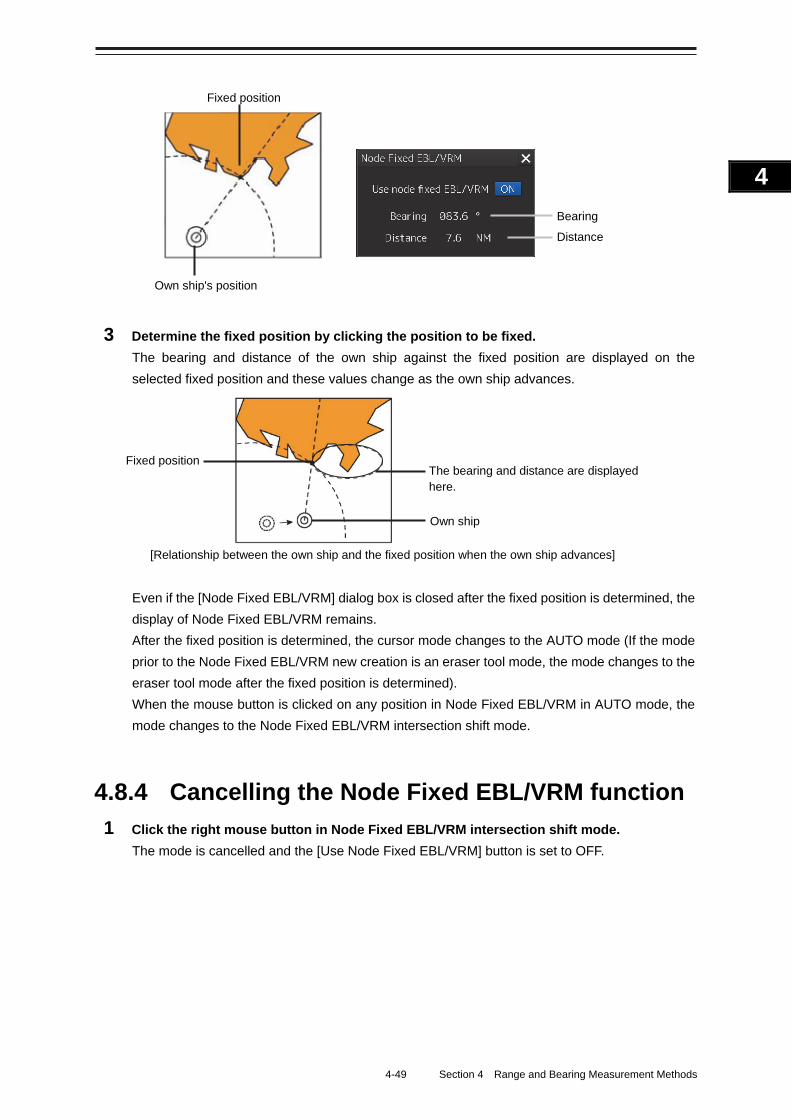
4-49 Section 4 Range and Bearing Measurement Methods
1
2
3
4
5
6
7
8
9
10
11
12
13
14
15
16
17
18
19
20
21
22
23
24
25
APP A
APP B
1
3 Determine the fixed position by clicking the position to be fixed.
The bearing and distance of the own ship against the fixed position are displayed on the
selected fixed position and these values change as the own ship advances.
[Relationship between the own ship and the fixed position when the own ship advances]
Even if the [Node Fixed EBL/VRM] dialog box is closed after the fixed position is determined, the
display of Node Fixed EBL/VRM remains.
After the fixed position is determined, the cursor mode changes to the AUTO mode (If the mode
prior to the Node Fixed EBL/VRM new creation is an eraser tool mode, the mode changes to the
eraser tool mode after the fixed position is determined).
When the mouse button is clicked on any position in Node Fixed EBL/VRM in AUTO mode, the
mode changes to the Node Fixed EBL/VRM intersection shift mode.
4.8.4 Cancelling the Node Fixed EBL/VRM function
1 Click the right mouse button in Node Fixed EBL/VRM intersection shift mode.
The mode is cancelled and the [Use Node Fixed EBL/VRM] button is set to OFF.
Fixed positionThe bearing and distance are displayed here.
Own ship
Fixed position
Own ship's position
Bearing Distance
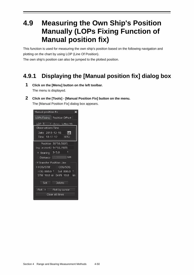
Section 4 Range and Bearing Measurement Methods 4-50
4.9 Measuring the Own Ship's Position Manually (LOPs Fixing Function of Manual position fix)
This function is used for measuring the own ship's position based on the following navigation and
plotting on the chart by using LOP (Line Of Position).
The own ship's position can also be jumped to the plotted position.
4.9.1 Displaying the [Manual position fix] dialog box
1 Click on the [Menu] button on the left toolbar.
The menu is displayed.
2 Click on the [Tools] - [Manual Position Fix] button on the menu.
The [Manual Position Fix] dialog box appears.
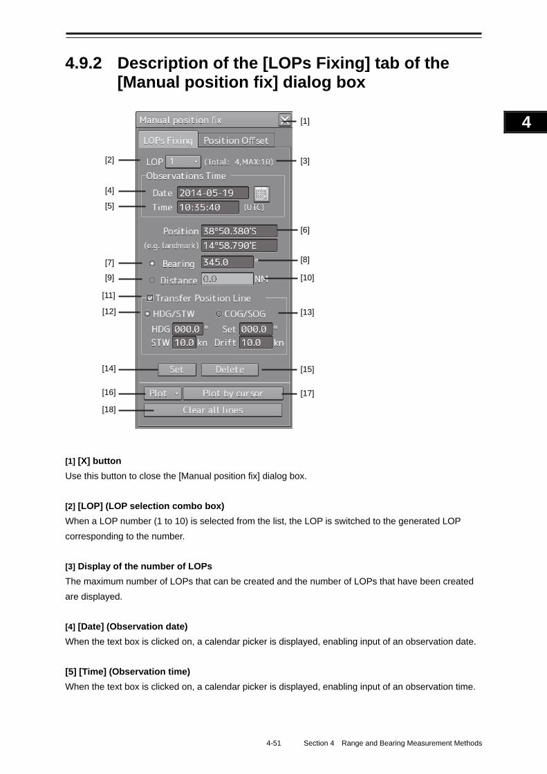
4-51 Section 4 Range and Bearing Measurement Methods
1
2
3
4
5
6
7
8
9
10
11
12
13
14
15
16
17
18
19
20
21
22
23
24
25
APP A
APP B
1
4.9.2 Description of the [LOPs Fixing] tab of the [Manual position fix] dialog box
[1] [X] button
Use this button to close the [Manual position fix] dialog box.
[2] [LOP] (LOP selection combo box)
When a LOP number (1 to 10) is selected from the list, the LOP is switched to the generated LOP
corresponding to the number.
[3] Display of the number of LOPs
The maximum number of LOPs that can be created and the number of LOPs that have been created
are displayed.
[4] [Date] (Observation date)
When the text box is clicked on, a calendar picker is displayed, enabling input of an observation date.
[5] [Time] (Observation time)
When the text box is clicked on, a calendar picker is displayed, enabling input of an observation time.
[1]
[3]
[6]
[8]
[10]
[13]
[15]
[17] [16]
[18]
[12]
[14]
[11]
[9] [7]
[5]
[4]
[2]
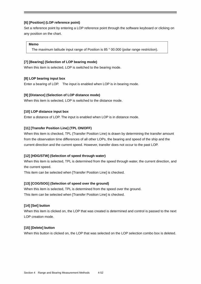
Section 4 Range and Bearing Measurement Methods 4-52
[6] [Position] (LOP reference point)
Set a reference point by entering a LOP reference point through the software keyboard or clicking on
any position on the chart.
Memo
The maximum latitude input range of Position is 85 ° 00.000 (polar range restriction).
[7] [Bearing] (Selection of LOP bearing mode)
When this item is selected, LOP is switched to the bearing mode.
[8] LOP bearing input box
Enter a bearing of LOP. The input is enabled when LOP is in bearing mode.
[9] [Distance] (Selection of LOP distance mode)
When this item is selected, LOP is switched to the distance mode.
[10] LOP distance input box
Enter a distance of LOP. The input is enabled when LOP is in distance mode.
[11] [Transfer Position Line] (TPL ON/OFF)
When this item is checked, TPL (Transfer Position Line) is drawn by determining the transfer amount
from the observation time differences of all other LOPs, the bearing and speed of the ship and the
current direction and the current speed. However, transfer does not occur to the past LOP.
[12] [HDG/STW] (Selection of speed through water)
When this item is selected, TPL is determined from the speed through water, the current direction, and
the current speed.
This item can be selected when [Transfer Position Line] is checked.
[13] [COG/SOG] (Selection of speed over the ground)
When this item is selected, TPL is determined from the speed over the ground.
This item can be selected when [Transfer Position Line] is checked.
[14] [Set] button
When this item is clicked on, the LOP that was created is determined and control is passed to the next
LOP creation mode.
[15] [Delete] button
When this button is clicked on, the LOP that was selected on the LOP selection combo box is deleted.
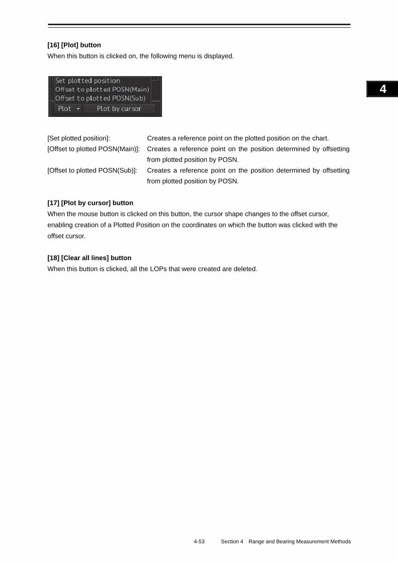
4-53 Section 4 Range and Bearing Measurement Methods
1
2
3
4
5
6
7
8
9
10
11
12
13
14
15
16
17
18
19
20
21
22
23
24
25
APP A
APP B
1
[16] [Plot] button
When this button is clicked on, the following menu is displayed.
[Set plotted position]: Creates a reference point on the plotted position on the chart.
[Offset to plotted POSN(Main)]: Creates a reference point on the position determined by offsetting
from plotted position by POSN.
[Offset to plotted POSN(Sub)]: Creates a reference point on the position determined by offsetting
from plotted position by POSN.
[17] [Plot by cursor] button
When the mouse button is clicked on this button, the cursor shape changes to the offset cursor,
enabling creation of a Plotted Position on the coordinates on which the button was clicked with the
offset cursor.
[18] [Clear all lines] button
When this button is clicked, all the LOPs that were created are deleted.
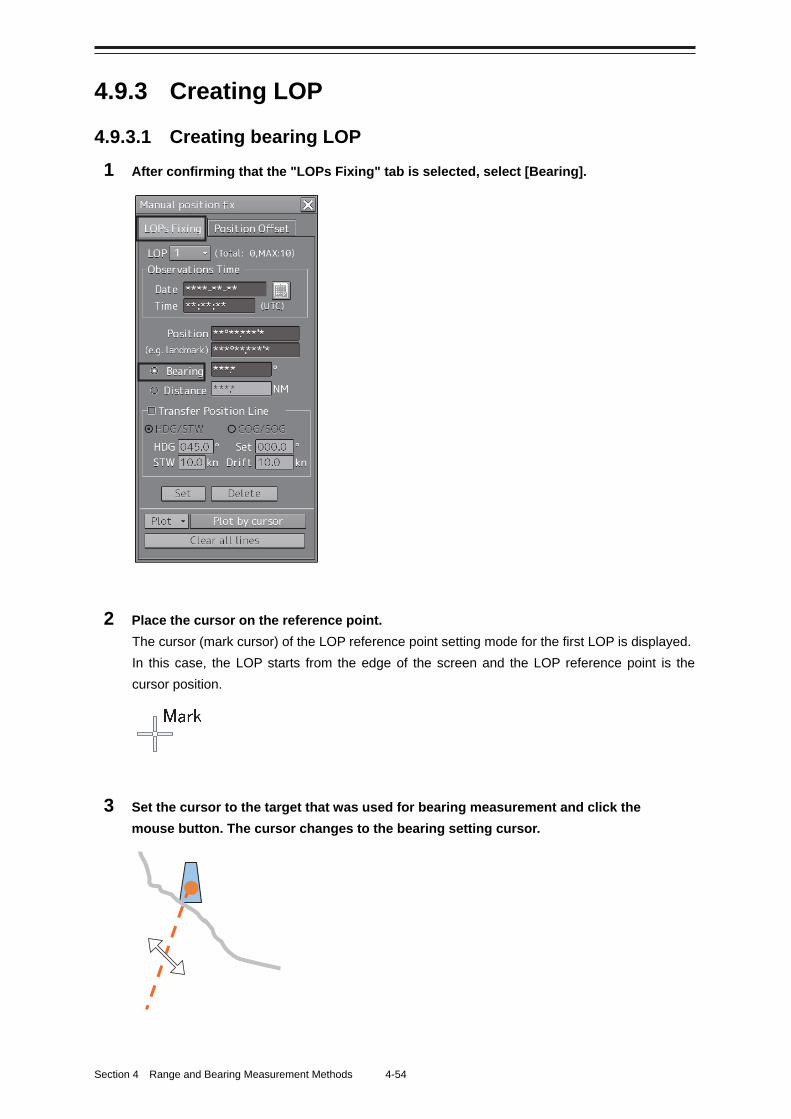
Section 4 Range and Bearing Measurement Methods 4-54
4.9.3 Creating LOP
4.9.3.1 Creating bearing LOP
1 After confirming that the "LOPs Fixing" tab is selected, select [Bearing].
2 Place the cursor on the reference point.
The cursor (mark cursor) of the LOP reference point setting mode for the first LOP is displayed.
In this case, the LOP starts from the edge of the screen and the LOP reference point is the
cursor position.
3 Set the cursor to the target that was used for bearing measurement and click the
mouse button. The cursor changes to the bearing setting cursor.
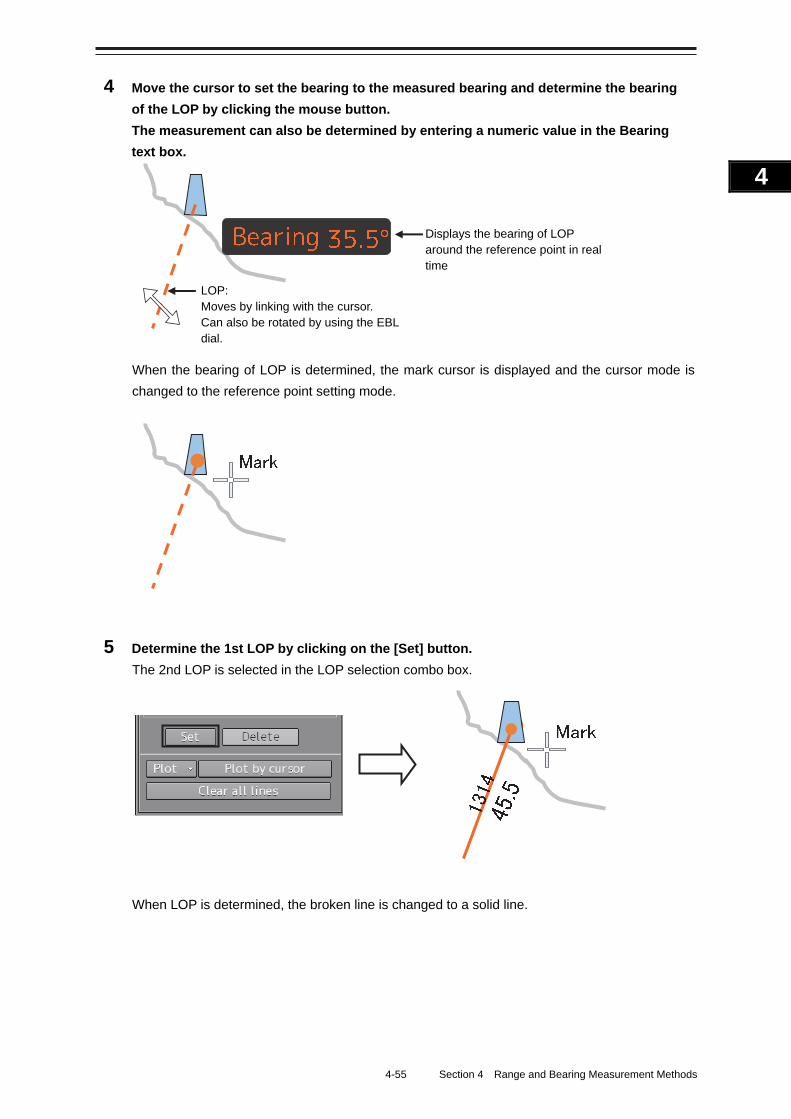
4-55 Section 4 Range and Bearing Measurement Methods
1
2
3
4
5
6
7
8
9
10
11
12
13
14
15
16
17
18
19
20
21
22
23
24
25
APP A
APP B
1
4 Move the cursor to set the bearing to the measured bearing and determine the bearing
of the LOP by clicking the mouse button.
The measurement can also be determined by entering a numeric value in the Bearing
text box.
When the bearing of LOP is determined, the mark cursor is displayed and the cursor mode is
changed to the reference point setting mode.
5 Determine the 1st LOP by clicking on the [Set] button.
The 2nd LOP is selected in the LOP selection combo box.
When LOP is determined, the broken line is changed to a solid line.
LOP: Moves by linking with the cursor. Can also be rotated by using the EBL dial.
Displays the bearing of LOP around the reference point in real time
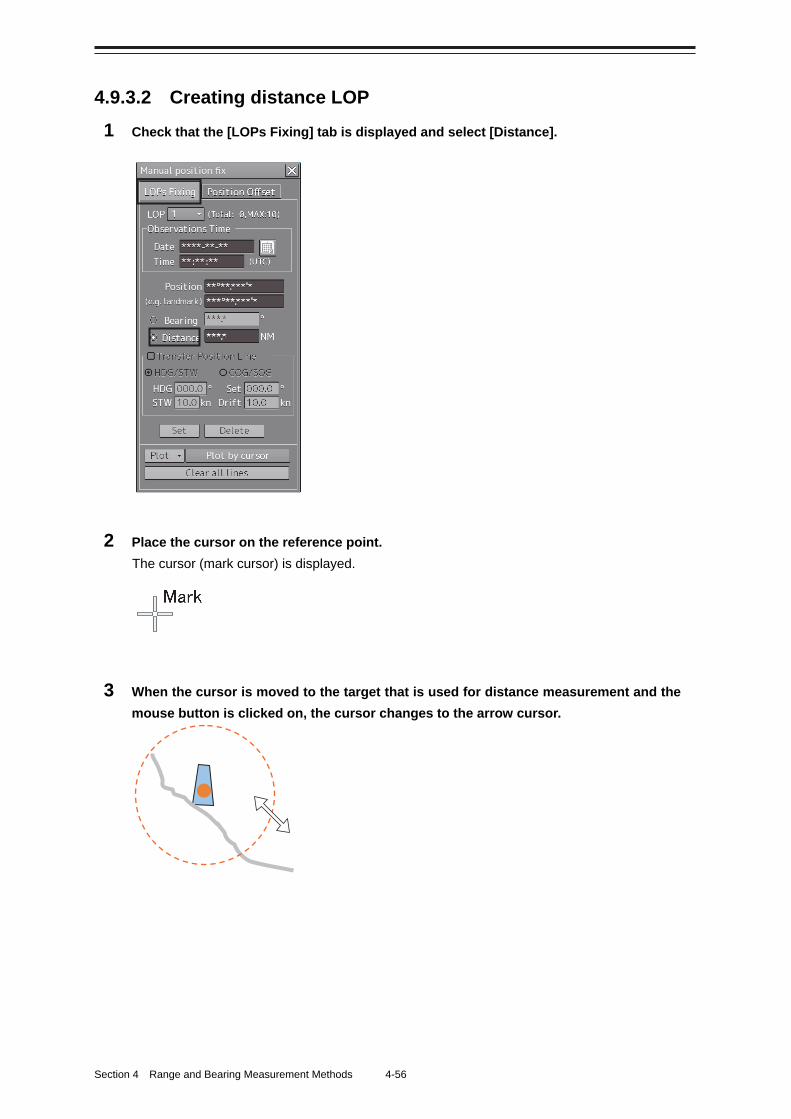
Section 4 Range and Bearing Measurement Methods 4-56
4.9.3.2 Creating distance LOP
1 Check that the [LOPs Fixing] tab is displayed and select [Distance].
2 Place the cursor on the reference point.
The cursor (mark cursor) is displayed.
3 When the cursor is moved to the target that is used for distance measurement and the
mouse button is clicked on, the cursor changes to the arrow cursor.
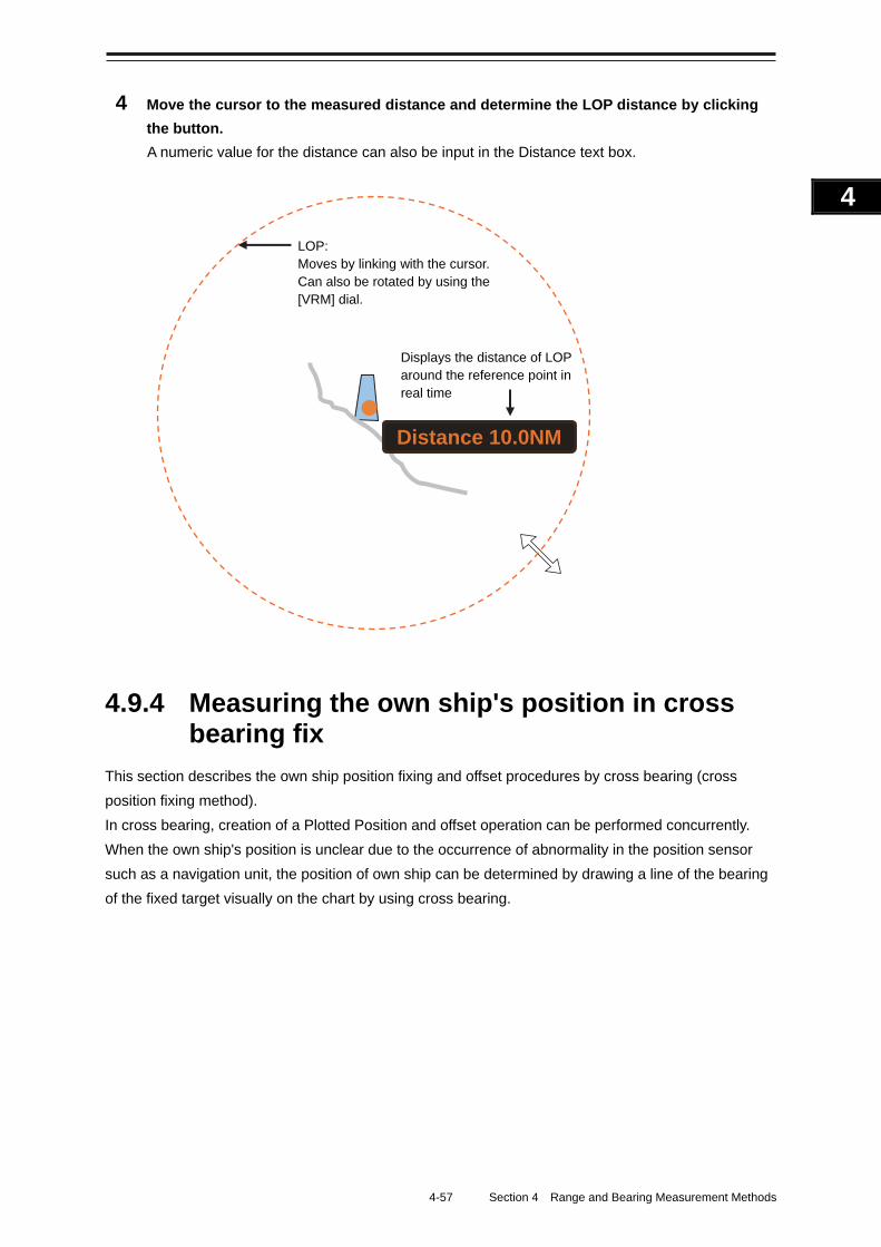
4-57 Section 4 Range and Bearing Measurement Methods
1
2
3
4
5
6
7
8
9
10
11
12
13
14
15
16
17
18
19
20
21
22
23
24
25
APP A
APP B
1
4 Move the cursor to the measured distance and determine the LOP distance by clicking
the button.
A numeric value for the distance can also be input in the Distance text box.
4.9.4 Measuring the own ship's position in cross bearing fix
This section describes the own ship position fixing and offset procedures by cross bearing (cross
position fixing method).
In cross bearing, creation of a Plotted Position and offset operation can be performed concurrently.
When the own ship's position is unclear due to the occurrence of abnormality in the position sensor
such as a navigation unit, the position of own ship can be determined by drawing a line of the bearing
of the fixed target visually on the chart by using cross bearing.
LOP: Moves by linking with the cursor. Can also be rotated by using the [VRM] dial.
Displays the distance of LOP around the reference point in real time
Distance 10.0NM
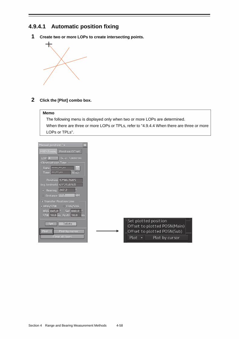
Section 4 Range and Bearing Measurement Methods 4-58
4.9.4.1 Automatic position fixing
1 Create two or more LOPs to create intersecting points.
2 Click the [Plot] combo box.
Memo
The following menu is displayed only when two or more LOPs are determined.
When there are three or more LOPs or TPLs, refer to "4.9.4.4 When there are three or more
LOPs or TPLs".
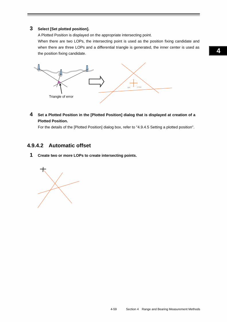
4-59 Section 4 Range and Bearing Measurement Methods
1
2
3
4
5
6
7
8
9
10
11
12
13
14
15
16
17
18
19
20
21
22
23
24
25
APP A
APP B
1
3 Select [Set plotted position].
A Plotted Position is displayed on the appropriate intersecting point.
When there are two LOPs, the intersecting point is used as the position fixing candidate and
when there are three LOPs and a differential triangle is generated, the inner center is used as
the position fixing candidate.
4 Set a Plotted Position in the [Plotted Position] dialog that is displayed at creation of a
Plotted Position.
For the details of the [Plotted Position] dialog box, refer to "4.9.4.5 Setting a plotted position".
4.9.4.2 Automatic offset
1 Create two or more LOPs to create intersecting points.
Triangle of error
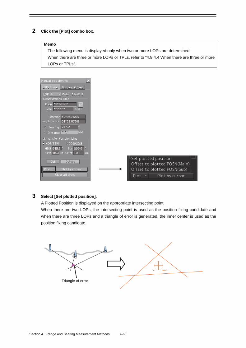
Section 4 Range and Bearing Measurement Methods 4-60
2 Click the [Plot] combo box.
Memo
The following menu is displayed only when two or more LOPs are determined.
When there are three or more LOPs or TPLs, refer to "4.9.4.4 When there are three or more
LOPs or TPLs".
3 Select [Set plotted position].
A Plotted Position is displayed on the appropriate intersecting point.
When there are two LOPs, the intersecting point is used as the position fixing candidate and
when there are three LOPs and a triangle of error is generated, the inner center is used as the
position fixing candidate.
Triangle of error
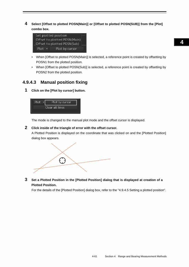
4-61 Section 4 Range and Bearing Measurement Methods
1
2
3
4
5
6
7
8
9
10
11
12
13
14
15
16
17
18
19
20
21
22
23
24
25
APP A
APP B
1
4 Select [Offset to plotted POSN(Main)] or [Offset to plotted POSN(SUB)] from the [Plot]
combo box.
• When [Offset to plotted POSN(Main)] is selected, a reference point is created by offsetting by
POSN1 from the plotted position.
• When [Offset to plotted POSN(Sub)] is selected, a reference point is created by offsetting by
POSN2 from the plotted position.
4.9.4.3 Manual position fixing
1 Click on the [Plot by cursor] button.
The mode is changed to the manual plot mode and the offset cursor is displayed.
2 Click inside of the triangle of error with the offset cursor.
A Plotted Position is displayed on the coordinate that was clicked on and the [Plotted Position]
dialog box appears.
3 Set a Plotted Position in the [Plotted Position] dialog that is displayed at creation of a
Plotted Position.
For the details of the [Plotted Position] dialog box, refer to the "4.9.4.5 Setting a plotted position".
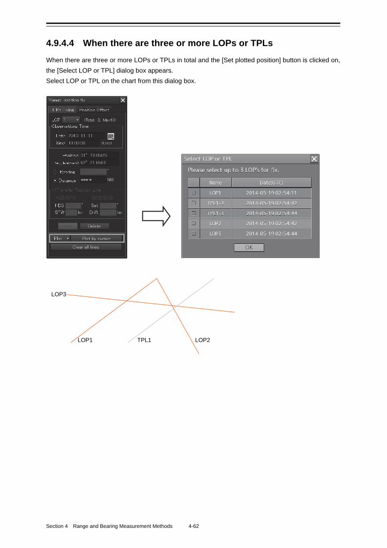
Section 4 Range and Bearing Measurement Methods 4-62
4.9.4.4 When there are three or more LOPs or TPLs
When there are three or more LOPs or TPLs in total and the [Set plotted position] button is clicked on,
the [Select LOP or TPL] dialog box appears.
Select LOP or TPL on the chart from this dialog box.
LOP3
LOP1 TPL1 LOP2
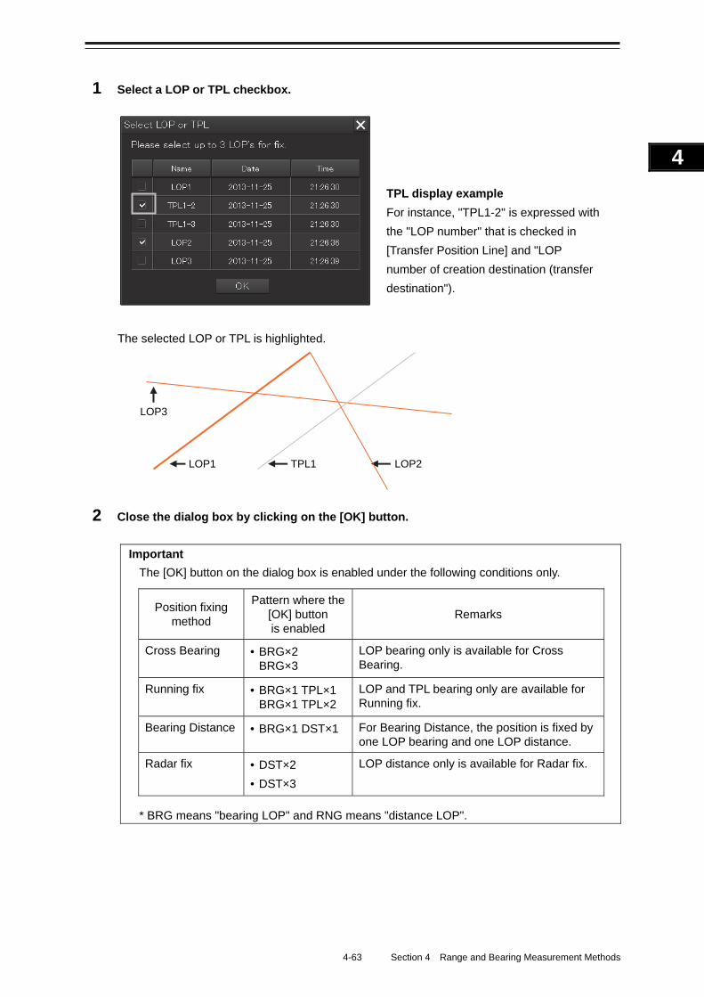
4-63 Section 4 Range and Bearing Measurement Methods
1
2
3
4
5
6
7
8
9
10
11
12
13
14
15
16
17
18
19
20
21
22
23
24
25
APP A
APP B
1
1 Select a LOP or TPL checkbox.
The selected LOP or TPL is highlighted.
2 Close the dialog box by clicking on the [OK] button.
Important
The [OK] button on the dialog box is enabled under the following conditions only.
Position fixing method
Pattern where the [OK] button is enabled
Remarks
Cross Bearing • BRG×2 BRG×3
LOP bearing only is available for Cross Bearing.
Running fix • BRG×1 TPL×1 BRG×1 TPL×2
LOP and TPL bearing only are available for Running fix.
Bearing Distance • BRG×1 DST×1 For Bearing Distance, the position is fixed by one LOP bearing and one LOP distance.
Radar fix • DST×2
• DST×3
LOP distance only is available for Radar fix.
* BRG means "bearing LOP" and RNG means "distance LOP".
LOP3
LOP1 TPL1 LOP2
TPL display example For instance, "TPL1-2" is expressed with
the "LOP number" that is checked in
[Transfer Position Line] and "LOP
number of creation destination (transfer
destination").
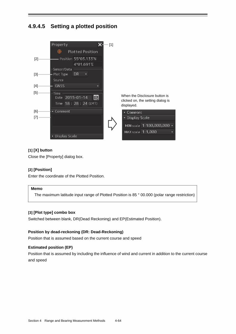
Section 4 Range and Bearing Measurement Methods 4-64
4.9.4.5 Setting a plotted position
[1] [X] button
Close the [Property] dialog box.
[2] [Position]
Enter the coordinate of the Plotted Position.
Memo
The maximum latitude input range of Plotted Position is 85 ° 00.000 (polar range restriction)
[3] [Plot type] combo box
Switched between blank, DR(Dead Reckoning) and EP(Estimated Position).
Position by dead-reckoning (DR: Dead-Reckoning)
Position that is assumed based on the current course and speed
Estimated position (EP)
Position that is assumed by including the influence of wind and current in addition to the current course
and speed
When the Disclosure button is clicked on, the setting dialog is displayed.
[1]
[6]
[5]
[4]
[3]
[2]
[7]
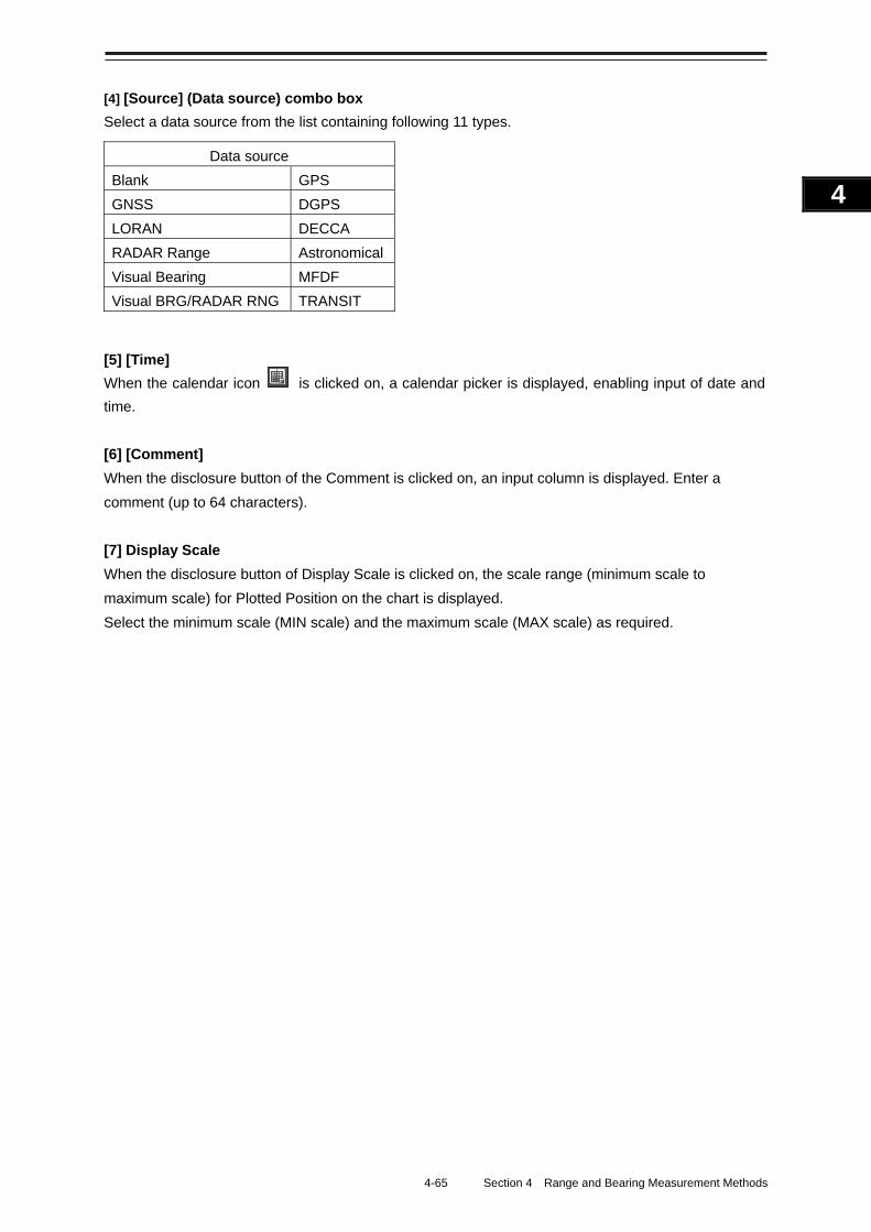
4-65 Section 4 Range and Bearing Measurement Methods
1
2
3
4
5
6
7
8
9
10
11
12
13
14
15
16
17
18
19
20
21
22
23
24
25
APP A
APP B
1
[4] [Source] (Data source) combo box
Select a data source from the list containing following 11 types.
Data source
Blank GPS
GNSS DGPS
LORAN DECCA
RADAR Range Astronomical
Visual Bearing MFDF
Visual BRG/RADAR RNG TRANSIT
[5] [Time]
When the calendar icon is clicked on, a calendar picker is displayed, enabling input of date and
time.
[6] [Comment]
When the disclosure button of the Comment is clicked on, an input column is displayed. Enter a
comment (up to 64 characters).
[7] Display Scale
When the disclosure button of Display Scale is clicked on, the scale range (minimum scale to
maximum scale) for Plotted Position on the chart is displayed.
Select the minimum scale (MIN scale) and the maximum scale (MAX scale) as required.
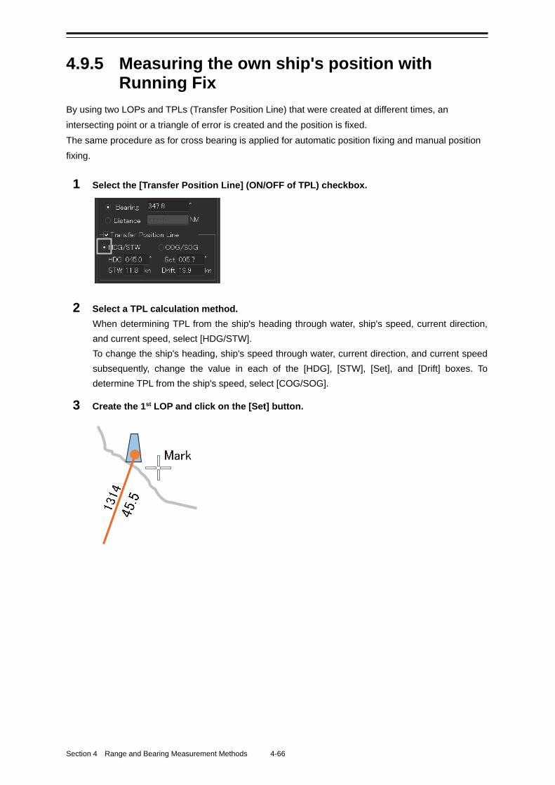
Section 4 Range and Bearing Measurement Methods 4-66
4.9.5 Measuring the own ship's position with Running Fix
By using two LOPs and TPLs (Transfer Position Line) that were created at different times, an
intersecting point or a triangle of error is created and the position is fixed.
The same procedure as for cross bearing is applied for automatic position fixing and manual position
fixing.
1 Select the [Transfer Position Line] (ON/OFF of TPL) checkbox.
2 Select a TPL calculation method.
When determining TPL from the ship's heading through water, ship's speed, current direction,
and current speed, select [HDG/STW].
To change the ship's heading, ship's speed through water, current direction, and current speed
subsequently, change the value in each of the [HDG], [STW], [Set], and [Drift] boxes. To
determine TPL from the ship's speed, select [COG/SOG].
3 Create the 1st LOP and click on the [Set] button.
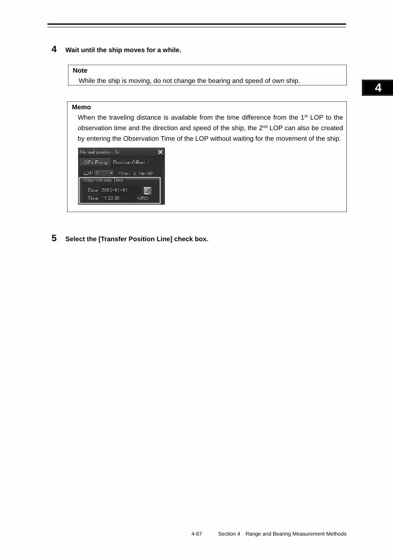
4-67 Section 4 Range and Bearing Measurement Methods
1
2
3
4
5
6
7
8
9
10
11
12
13
14
15
16
17
18
19
20
21
22
23
24
25
APP A
APP B
1
4 Wait until the ship moves for a while.
Note
While the ship is moving, do not change the bearing and speed of own ship.
Memo
When the traveling distance is available from the time difference from the 1st LOP to the
observation time and the direction and speed of the ship, the 2nd LOP can also be created
by entering the Observation Time of the LOP without waiting for the movement of the ship.
5 Select the [Transfer Position Line] check box.
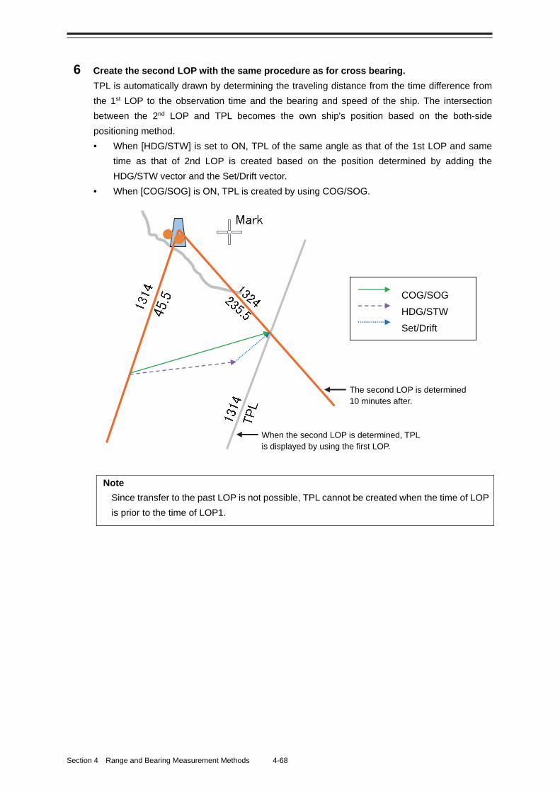
Section 4 Range and Bearing Measurement Methods 4-68
6 Create the second LOP with the same procedure as for cross bearing.
TPL is automatically drawn by determining the traveling distance from the time difference from
the 1st LOP to the observation time and the bearing and speed of the ship. The intersection
between the 2nd LOP and TPL becomes the own ship's position based on the both-side
positioning method.
• When [HDG/STW] is set to ON, TPL of the same angle as that of the 1st LOP and same
time as that of 2nd LOP is created based on the position determined by adding the
HDG/STW vector and the Set/Drift vector.
• When [COG/SOG] is ON, TPL is created by using COG/SOG.
Note
Since transfer to the past LOP is not possible, TPL cannot be created when the time of LOP
is prior to the time of LOP1.
COG/SOG
HDG/STW
Set/Drift
The second LOP is determined 10 minutes after.
When the second LOP is determined, TPL is displayed by using the first LOP.
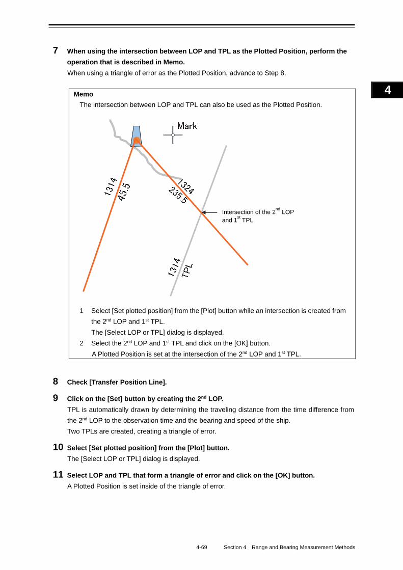
4-69 Section 4 Range and Bearing Measurement Methods
1
2
3
4
5
6
7
8
9
10
11
12
13
14
15
16
17
18
19
20
21
22
23
24
25
APP A
APP B
1
7 When using the intersection between LOP and TPL as the Plotted Position, perform the
operation that is described in Memo.
When using a triangle of error as the Plotted Position, advance to Step 8.
Memo
The intersection between LOP and TPL can also be used as the Plotted Position.
1 Select [Set plotted position] from the [Plot] button while an intersection is created from
the 2nd LOP and 1st TPL.
The [Select LOP or TPL] dialog is displayed.
2 Select the 2nd LOP and 1st TPL and click on the [OK] button.
A Plotted Position is set at the intersection of the 2nd LOP and 1st TPL.
8 Check [Transfer Position Line].
9 Click on the [Set] button by creating the 2nd LOP.
TPL is automatically drawn by determining the traveling distance from the time difference from
the 2nd LOP to the observation time and the bearing and speed of the ship.
Two TPLs are created, creating a triangle of error.
10 Select [Set plotted position] from the [Plot] button.
The [Select LOP or TPL] dialog is displayed.
11 Select LOP and TPL that form a triangle of error and click on the [OK] button.
A Plotted Position is set inside of the triangle of error.
Intersection of the 2nd
LOP and 1
st TPL
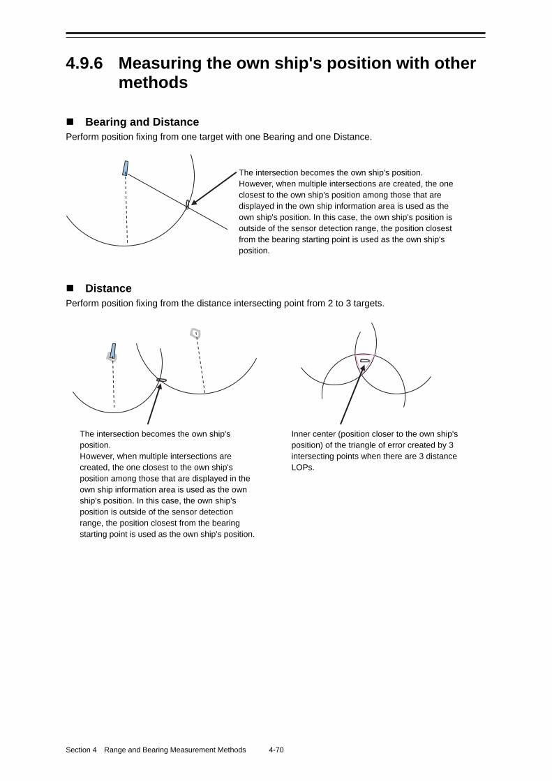
Section 4 Range and Bearing Measurement Methods 4-70
4.9.6 Measuring the own ship's position with other methods
Bearing and Distance Perform position fixing from one target with one Bearing and one Distance.
Distance Perform position fixing from the distance intersecting point from 2 to 3 targets.
The intersection becomes the own ship's position. However, when multiple intersections are created, the one closest to the own ship's position among those that are displayed in the own ship information area is used as the own ship's position. In this case, the own ship's position is outside of the sensor detection range, the position closest from the bearing starting point is used as the own ship's position.
Inner center (position closer to the own ship's position) of the triangle of error created by 3 intersecting points when there are 3 distance LOPs.
The intersection becomes the own ship's position. However, when multiple intersections are created, the one closest to the own ship's position among those that are displayed in the own ship information area is used as the own ship's position. In this case, the own ship's position is outside of the sensor detection range, the position closest from the bearing starting point is used as the own ship's position.
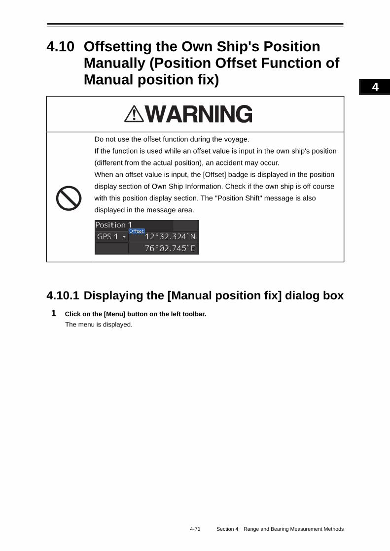
4-71 Section 4 Range and Bearing Measurement Methods
1
2
3
4
5
6
7
8
9
10
11
12
13
14
15
16
17
18
19
20
21
22
23
24
25
APP A
APP B
1
4.10 Offsetting the Own Ship's Position Manually (Position Offset Function of Manual position fix)
Do not use the offset function during the voyage.
If the function is used while an offset value is input in the own ship's position
(different from the actual position), an accident may occur.
When an offset value is input, the [Offset] badge is displayed in the position
display section of Own Ship Information. Check if the own ship is off course
with this position display section. The "Position Shift" message is also
displayed in the message area.
4.10.1 Displaying the [Manual position fix] dialog box
1 Click on the [Menu] button on the left toolbar.
The menu is displayed.
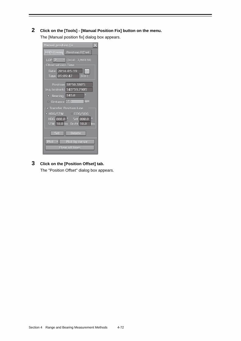
Section 4 Range and Bearing Measurement Methods 4-72
2 Click on the [Tools] - [Manual Position Fix] button on the menu.
The [Manual position fix] dialog box appears.
3 Click on the [Position Offset] tab.
The "Position Offset" dialog box appears.
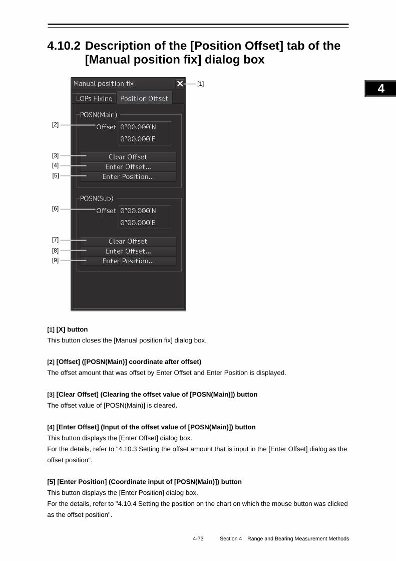
4-73 Section 4 Range and Bearing Measurement Methods
1
2
3
4
5
6
7
8
9
10
11
12
13
14
15
16
17
18
19
20
21
22
23
24
25
APP A
APP B
1
4.10.2 Description of the [Position Offset] tab of the [Manual position fix] dialog box
[1] [X] button
This button closes the [Manual position fix] dialog box.
[2] [Offset] ([POSN(Main)] coordinate after offset)
The offset amount that was offset by Enter Offset and Enter Position is displayed.
[3] [Clear Offset] (Clearing the offset value of [POSN(Main)]) button
The offset value of [POSN(Main)] is cleared.
[4] [Enter Offset] (Input of the offset value of [POSN(Main)]) button
This button displays the [Enter Offset] dialog box.
For the details, refer to "4.10.3 Setting the offset amount that is input in the [Enter Offset] dialog as the
offset position".
[5] [Enter Position] (Coordinate input of [POSN(Main)]) button
This button displays the [Enter Position] dialog box.
For the details, refer to "4.10.4 Setting the position on the chart on which the mouse button was clicked
as the offset position".
[1]
[8] [9]
[7]
[6]
[5] [4] [3]
[2]
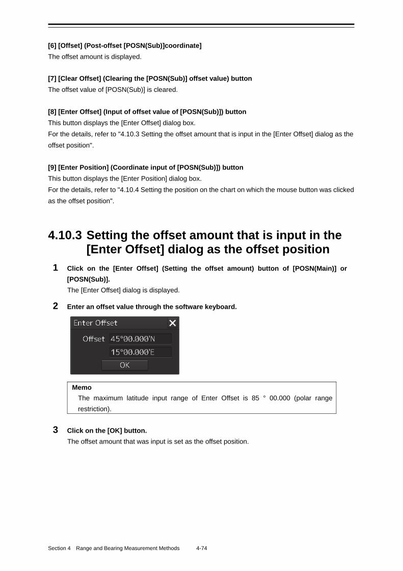
Section 4 Range and Bearing Measurement Methods 4-74
[6] [Offset] (Post-offset [POSN(Sub)]coordinate]
The offset amount is displayed.
[7] [Clear Offset] (Clearing the [POSN(Sub)] offset value) button
The offset value of [POSN(Sub)] is cleared.
[8] [Enter Offset] (Input of offset value of [POSN(Sub)]) button
This button displays the [Enter Offset] dialog box.
For the details, refer to "4.10.3 Setting the offset amount that is input in the [Enter Offset] dialog as the
offset position".
[9] [Enter Position] (Coordinate input of [POSN(Sub)]) button
This button displays the [Enter Position] dialog box.
For the details, refer to "4.10.4 Setting the position on the chart on which the mouse button was clicked
as the offset position".
4.10.3 Setting the offset amount that is input in the [Enter Offset] dialog as the offset position
1 Click on the [Enter Offset] (Setting the offset amount) button of [POSN(Main)] or
[POSN(Sub)].
The [Enter Offset] dialog is displayed.
2 Enter an offset value through the software keyboard.
Memo
The maximum latitude input range of Enter Offset is 85 ° 00.000 (polar range
restriction).
3 Click on the [OK] button.
The offset amount that was input is set as the offset position.
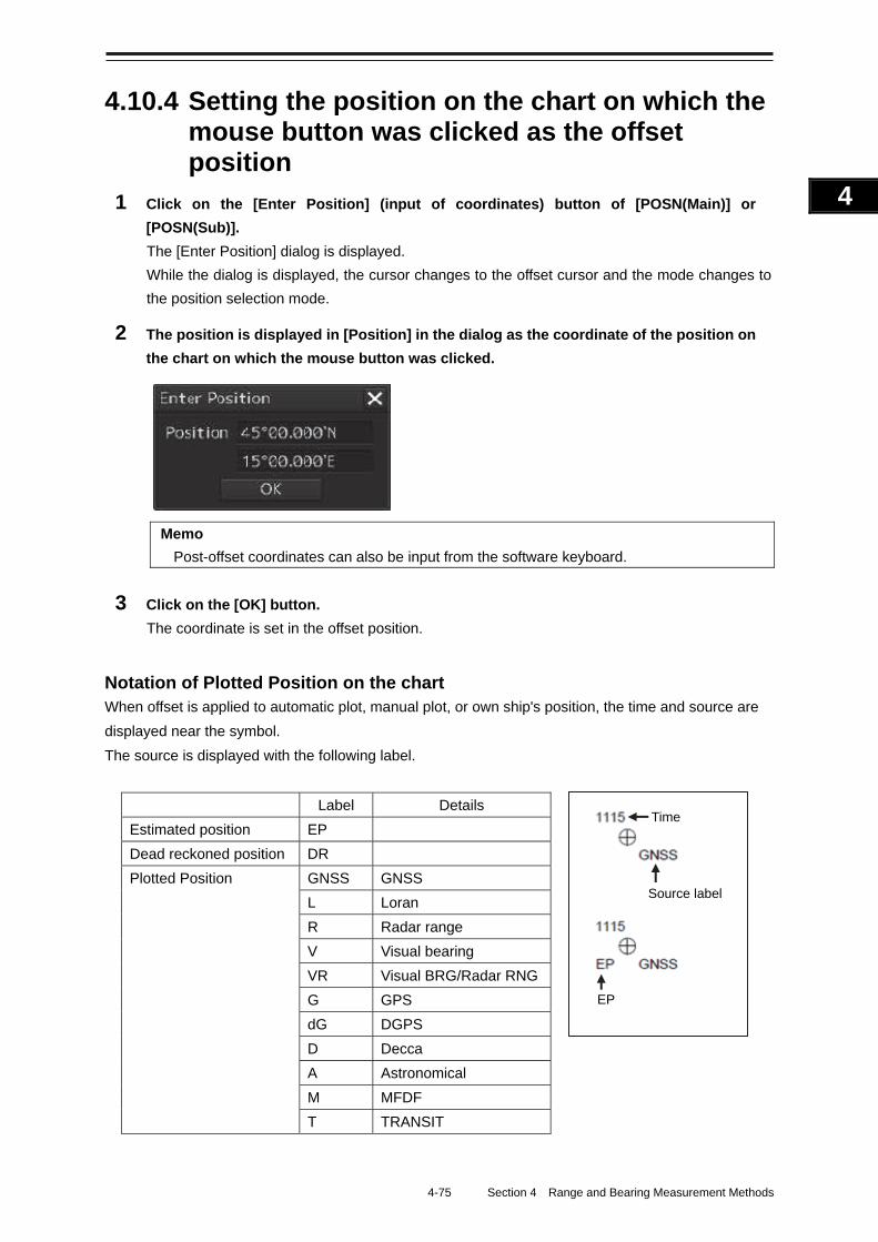
4-75 Section 4 Range and Bearing Measurement Methods
1
2
3
4
5
6
7
8
9
10
11
12
13
14
15
16
17
18
19
20
21
22
23
24
25
APP A
APP B
1
4.10.4 Setting the position on the chart on which the mouse button was clicked as the offset position
1 Click on the [Enter Position] (input of coordinates) button of [POSN(Main)] or
[POSN(Sub)].
The [Enter Position] dialog is displayed.
While the dialog is displayed, the cursor changes to the offset cursor and the mode changes to
the position selection mode.
2 The position is displayed in [Position] in the dialog as the coordinate of the position on
the chart on which the mouse button was clicked.
Memo
Post-offset coordinates can also be input from the software keyboard.
3 Click on the [OK] button.
The coordinate is set in the offset position.
Notation of Plotted Position on the chart When offset is applied to automatic plot, manual plot, or own ship's position, the time and source are
displayed near the symbol.
The source is displayed with the following label.
Source label
Time
EP
Label Details
Estimated position EP
Dead reckoned position DR
Plotted Position GNSS GNSS
L Loran
R Radar range
V Visual bearing
VR Visual BRG/Radar RNG
G GPS
dG DGPS
D Decca
A Astronomical
M MFDF
T TRANSIT
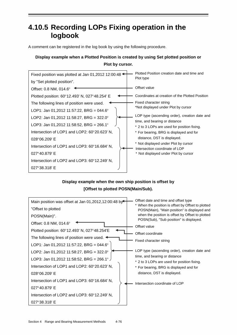
Section 4 Range and Bearing Measurement Methods 4-76
4.10.5 Recording LOPs Fixing operation in the logbook
A comment can be registered in the log book by using the following procedure.
Display example when a Plotted Position is created by using Set plotted position or
Plot by cursor.
Display example when the own ship position is offset by
[Offset to plotted POSN(Main/Sub).
Main position was offset at Jan 01,2012,12:00:48 by
"Offset to plotted
POSN(Main)".
Offset: 0.8 NM, 014.6
Plotted position: 6012.493' N, 02748.254'E
The following lines of position were used.
LOP1: Jan 01,2012 11:57:22, BRG = 044.6
LOP2: Jan 01,2012 11:58:27, BRG = 322.0
LOP3: Jan 01,2012 11:58:52, BRG = 266.1
Intersection of LOP1 and LOP2: 6020.623' N,
02806.209' E
Intersection of LOP1 and LOP3: 6016.684' N,
02740.879' E
Intersection of LOP2 and LOP3: 6012.249' N,
02738.318' E
Offset date and time and offset type * When the position is offset by Offset to plotted
POSN(Main), "Main position" is displayed and when the position is offset by Offset to plotted POSN(Sub), "Sub position" is displayed.
Intersection coordinate of LOP
Offset value
LOP type (ascending order), creation date and
time, and bearing or distance * 2 to 3 LOPs are used for position fixing. * For bearing, BRG is displayed and for
distance, DST is displayed.
Offset coordinate
Fixed character string
Fixed position was plotted at Jan 01,2012 12:00:48
by "Set plotted position".
Offset: 0.8 NM, 014.6
Plotted position: 6012.493' N, 02748.254' E
The following lines of position were used.
LOP1: Jan 01,2012 11:57:22, BRG = 044.6
LOP2: Jan 01,2012 11:58:27, BRG = 322.0
LOP3: Jan 01,2012 11:58:52, BRG = 266.1
Intersection of LOP1 and LOP2: 6020.623' N,
02806.209' E
Intersection of LOP1 and LOP3: 6016.684' N,
02740.879' E
Intersection of LOP2 and LOP3: 6012.249' N,
02738.318' E
Coordinates at creation of the Plotted Position Fixed character string *Not displayed under Plot by cursor
Intersection coordinate of LOP * Not displayed under Plot by cursor
Offset value
LOP type (ascending order), creation date and
time, and bearing or distance * 2 to 3 LOPs are used for position fixing. * For bearing, BRG is displayed and for
distance, DST is displayed. * Not displayed under Plot by cursor
Plotted Position creation date and time and Plot type
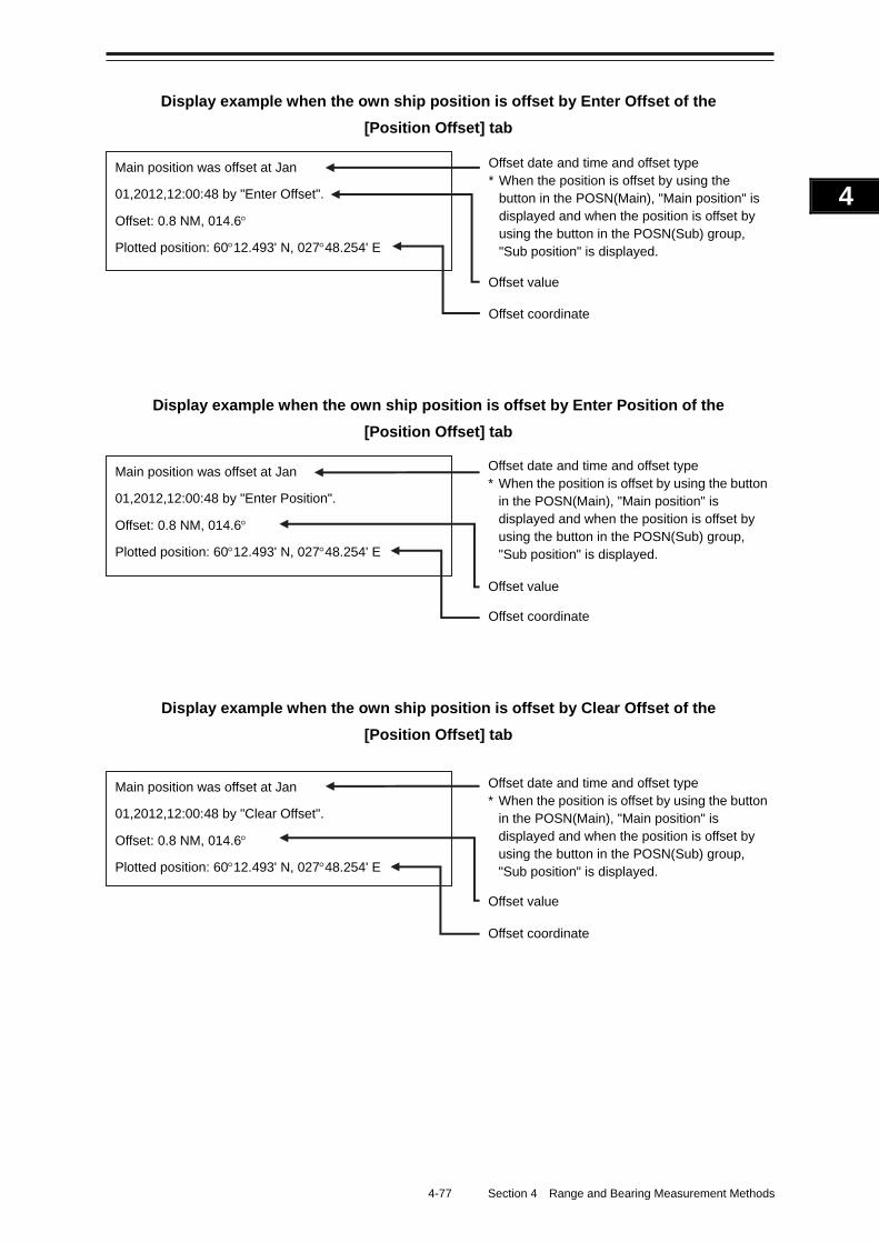
4-77 Section 4 Range and Bearing Measurement Methods
1
2
3
4
5
6
7
8
9
10
11
12
13
14
15
16
17
18
19
20
21
22
23
24
25
APP A
APP B
1
Display example when the own ship position is offset by Enter Offset of the
[Position Offset] tab
Display example when the own ship position is offset by Enter Position of the
[Position Offset] tab
Display example when the own ship position is offset by Clear Offset of the
[Position Offset] tab
Main position was offset at Jan
01,2012,12:00:48 by "Clear Offset".
Offset: 0.8 NM, 014.6
Plotted position: 6012.493' N, 02748.254' E
Offset date and time and offset type * When the position is offset by using the button
in the POSN(Main), "Main position" is displayed and when the position is offset by using the button in the POSN(Sub) group, "Sub position" is displayed.
Offset value
Offset coordinate
Main position was offset at Jan
01,2012,12:00:48 by "Enter Position".
Offset: 0.8 NM, 014.6
Plotted position: 6012.493' N, 02748.254' E
Offset date and time and offset type * When the position is offset by using the button
in the POSN(Main), "Main position" is displayed and when the position is offset by using the button in the POSN(Sub) group, "Sub position" is displayed.
Offset value
Offset coordinate
Main position was offset at Jan
01,2012,12:00:48 by "Enter Offset".
Offset: 0.8 NM, 014.6
Plotted position: 6012.493' N, 02748.254' E
Offset date and time and offset type * When the position is offset by using the
button in the POSN(Main), "Main position" is displayed and when the position is offset by using the button in the POSN(Sub) group, "Sub position" is displayed.
Offset value
Offset coordinate
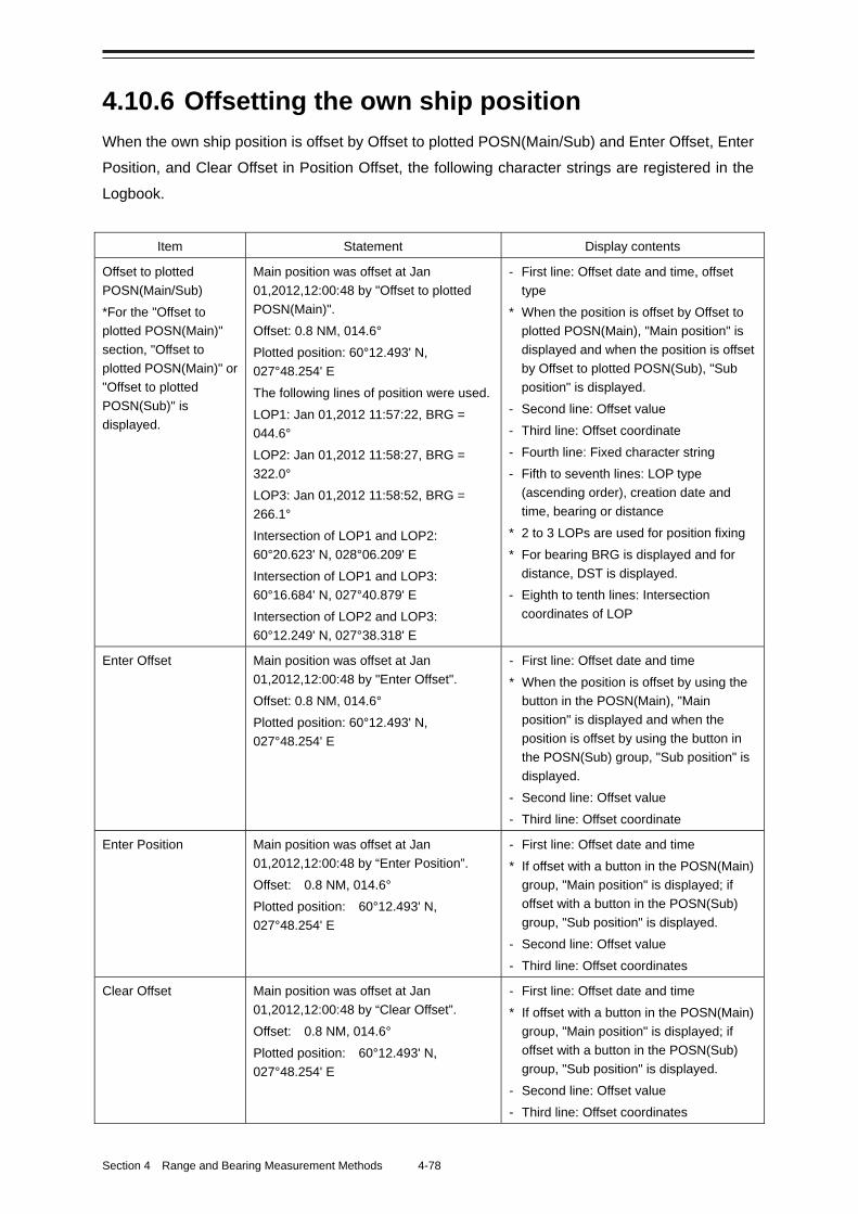
Section 4 Range and Bearing Measurement Methods 4-78
4.10.6 Offsetting the own ship position
When the own ship position is offset by Offset to plotted POSN(Main/Sub) and Enter Offset, Enter
Position, and Clear Offset in Position Offset, the following character strings are registered in the
Logbook.
Item Statement Display contents
Offset to plotted
POSN(Main/Sub)
*For the "Offset to
plotted POSN(Main)"
section, "Offset to
plotted POSN(Main)" or
"Offset to plotted
POSN(Sub)" is
displayed.
Main position was offset at Jan
01,2012,12:00:48 by "Offset to plotted
POSN(Main)".
Offset: 0.8 NM, 014.6°
Plotted position: 60°12.493' N,
027°48.254' E
The following lines of position were used.
LOP1: Jan 01,2012 11:57:22, BRG =
044.6°
LOP2: Jan 01,2012 11:58:27, BRG =
322.0°
LOP3: Jan 01,2012 11:58:52, BRG =
266.1°
Intersection of LOP1 and LOP2:
60°20.623' N, 028°06.209' E
Intersection of LOP1 and LOP3:
60°16.684' N, 027°40.879' E
Intersection of LOP2 and LOP3:
60°12.249' N, 027°38.318' E
- First line: Offset date and time, offset
type
* When the position is offset by Offset to
plotted POSN(Main), "Main position" is
displayed and when the position is offset
by Offset to plotted POSN(Sub), "Sub
position" is displayed.
- Second line: Offset value
- Third line: Offset coordinate
- Fourth line: Fixed character string
- Fifth to seventh lines: LOP type
(ascending order), creation date and
time, bearing or distance
* 2 to 3 LOPs are used for position fixing
* For bearing BRG is displayed and for
distance, DST is displayed.
- Eighth to tenth lines: Intersection
coordinates of LOP
Enter Offset Main position was offset at Jan
01,2012,12:00:48 by "Enter Offset".
Offset: 0.8 NM, 014.6°
Plotted position: 60°12.493' N,
027°48.254' E
- First line: Offset date and time
* When the position is offset by using the
button in the POSN(Main), "Main
position" is displayed and when the
position is offset by using the button in
the POSN(Sub) group, "Sub position" is
displayed.
- Second line: Offset value
- Third line: Offset coordinate
Enter Position Main position was offset at Jan
01,2012,12:00:48 by “Enter Position”.
Offset: 0.8 NM, 014.6°
Plotted position: 60°12.493' N,
027°48.254' E
- First line: Offset date and time
* If offset with a button in the POSN(Main)
group, "Main position" is displayed; if
offset with a button in the POSN(Sub)
group, "Sub position" is displayed.
- Second line: Offset value
- Third line: Offset coordinates
Clear Offset Main position was offset at Jan
01,2012,12:00:48 by “Clear Offset”.
Offset: 0.8 NM, 014.6°
Plotted position: 60°12.493' N,
027°48.254' E
- First line: Offset date and time
* If offset with a button in the POSN(Main)
group, "Main position" is displayed; if
offset with a button in the POSN(Sub)
group, "Sub position" is displayed.
- Second line: Offset value
- Third line: Offset coordinates


ISO 9001, ISO 14001 Certified
FEB. 2020 Edition 9CODE No.7ZPNA4446H
Not use the asbestos
For further information,contact:
URL Head office : http://www.jrc.co.jp/eng/
Marine Service Department
1-7-32 Tatsumi, Koto-ku, Tokyo 135-0053, Japan
: +81-50-3786-9201e-mailOne-call
Overview 1 Name and Function of Each Unit 2 Common Basic Operations 3 Range and Bearing Measurement Methods 4 Basic Operation of the Radar 5 Target Tracking and AIS 6 True and False Echoes on Display 7 Functions of the ECDIS (Option) 8 Route Planning 9 Route Monitoring 10 Monitoring a Dragging Anchor 11 Automatic Sailing (Option) 12 Operating a Chart (Option) 13 Creating a User Chart/ Updating a ChartManually 14 Logbook 15 Setting Up Screen View 16 Setting Up Alerts 17 Setting Up the Operation Mode 18 Adjusting and Setting Up Equipment (for Services) 19 Playing Back Data Recorded DuringNavigation [Playback] 20 Maintenance & Inspection 21 Failures and After-Sale Services 22 About Disposal 23 Specifications 24 Radar Antenna Block Diagrams APP A
Alert List APP B
Setting the Interswitch APP C
Menu List and Materials APP D
JMR-7230-S3/SJMR-7225-7X3/9X3/6X/9X/6XH JMR-7210-6X/6XHJMR-7272-S JMR-7282-S/SH JMR-9230-S3/SJMR-9225-7X3/9X3/6X/9X/6XH JMR-9210-6X/6XHJMR-9272-S JMR-9282-S/SH
Marine Radar Equipment
Instruction Manual <Basic Operation>
Related Documents