Marine Installation Manual X82-B Issue 2019-05

Welcome message from author
This document is posted to help you gain knowledge. Please leave a comment to let me know what you think about it! Share it to your friends and learn new things together.
Transcript

Marine Installation Manual
X82-BIssue 2019-05

© 2019 Winterthur Gas & Diesel Ltd. — All rights reserved
No part of this publication may be reproduced or copied in any form or by any means (electronic, mechanical, graphic, photo-copying, recording, taping or other information retrieval systems) without the prior written permission of the copyright holder. Winterthur Gas & Diesel Ltd. makes no representation, warranty (express or implied) in this publication and assumes no re-sponsibility for the correctness, errors or omissions of information contained herein. Information in this publication is subjectto change without notice.
NO LIABILITY, WHETHER DIRECT, INDIRECT, SPECIAL, INCIDENTAL OR CONSEQUENTIAL, IS ASSUMED WITH RESPECT TO THE INFORMATION CONTAINED HEREIN. THIS PUBLICATION IS INTENDED FOR INFORMATION PURPOSES ONLY.

Marine Installation Manual 2019-05 1
List of ChangesX82-B
List of Changes
Revision: -- Date of issue: 2019-05
Location of change Subject
Entire document The present Marine Installation Manual (MIM) is published in a completely new version with a new layout. It supersedes former MIM version ‘a2’ dated 28 February 2017. All future changes and updates (revisions) will be tracked and described based on the present Manual.

Marine Installation Manual 2019-05 i
Table of ContentsX82-B
Table of Contents
List of Changes . . . . . . . . . . . . . . . . . . . . . . . . . . . . . . . . . . . . . . . . . . . . . . . . . . 0-1
0 Preface . . . . . . . . . . . . . . . . . . . . . . . . . . . . . . . . . . . . . . . . . . . . . . . . . . . . . . . . 0-1Introduction . . . . . . . . . . . . . . . . . . . . . . . . . . . . . . . . . . . . . . . . . . . . . . . . . . . . . 0-1Marine Installation Drawing Set . . . . . . . . . . . . . . . . . . . . . . . . . . . . . . . . . . . . . 0-2Explanation of symbols used in this manual . . . . . . . . . . . . . . . . . . . . . . . . . . . . 0-3
1 Engine Description . . . . . . . . . . . . . . . . . . . . . . . . . . . . . . . . . . . . . . . . . . . . . . 1-11.1 Power/speed range . . . . . . . . . . . . . . . . . . . . . . . . . . . . . . . . . . . . . . . . . 1-21.2 Primary engine data . . . . . . . . . . . . . . . . . . . . . . . . . . . . . . . . . . . . . . . . . 1-31.3 Components and sizes of the engine . . . . . . . . . . . . . . . . . . . . . . . . . . . . 1-4
Design features. . . . . . . . . . . . . . . . . . . . . . . . . . . . . . . . . . . . . . . . . . . . . 1-51.4 Engine tuning . . . . . . . . . . . . . . . . . . . . . . . . . . . . . . . . . . . . . . . . . . . . . . 1-61.4.1 BSFC and NOx emission . . . . . . . . . . . . . . . . . . . . . . . . . . . . . . . . . . . 1-71.4.2 Standard tuning . . . . . . . . . . . . . . . . . . . . . . . . . . . . . . . . . . . . . . . . . . 1-81.4.3 Delta tuning . . . . . . . . . . . . . . . . . . . . . . . . . . . . . . . . . . . . . . . . . . . . . 1-81.4.4 Delta bypass tuning . . . . . . . . . . . . . . . . . . . . . . . . . . . . . . . . . . . . . . . 1-8
Exhaust gas waste gate. . . . . . . . . . . . . . . . . . . . . . . . . . . . . . . . . . . . 1-9Exhaust gas temperature. . . . . . . . . . . . . . . . . . . . . . . . . . . . . . . . . . . 1-10Steam production. . . . . . . . . . . . . . . . . . . . . . . . . . . . . . . . . . . . . . . . . 1-10
1.4.5 Low load tuning . . . . . . . . . . . . . . . . . . . . . . . . . . . . . . . . . . . . . . . . . . 1-111.4.6 Steam production control (SPC) . . . . . . . . . . . . . . . . . . . . . . . . . . . . . 1-111.4.7 Waste heat recovery (WHR) . . . . . . . . . . . . . . . . . . . . . . . . . . . . . . . . 1-121.4.8 Low torsional vibration tuning (LowTV) . . . . . . . . . . . . . . . . . . . . . . . . 1-131.4.9 Tuning for de-rated engines. . . . . . . . . . . . . . . . . . . . . . . . . . . . . . . . . 1-141.4.10 Dual tuning. . . . . . . . . . . . . . . . . . . . . . . . . . . . . . . . . . . . . . . . . . . . . . 1-151.5 The Flex system . . . . . . . . . . . . . . . . . . . . . . . . . . . . . . . . . . . . . . . . . . . . 1-16
2 General Engine Data . . . . . . . . . . . . . . . . . . . . . . . . . . . . . . . . . . . . . . . . . . . . . 2-12.1 Pressure and temperature ranges . . . . . . . . . . . . . . . . . . . . . . . . . . . . . . 2-12.2 Engine rating field and power range . . . . . . . . . . . . . . . . . . . . . . . . . . . . . 2-22.2.1 Introduction . . . . . . . . . . . . . . . . . . . . . . . . . . . . . . . . . . . . . . . . . . . . . 2-22.2.2 Engine rating field . . . . . . . . . . . . . . . . . . . . . . . . . . . . . . . . . . . . . . . . 2-2
Rating points . . . . . . . . . . . . . . . . . . . . . . . . . . . . . . . . . . . . . . . . . . . . 2-32.2.3 Propeller diameter and influence of propeller revolutions . . . . . . . . . . 2-32.2.4 Power range. . . . . . . . . . . . . . . . . . . . . . . . . . . . . . . . . . . . . . . . . . . . . 2-4
Propeller curves and operational points. . . . . . . . . . . . . . . . . . . . . . . . 2-4Sea trial power . . . . . . . . . . . . . . . . . . . . . . . . . . . . . . . . . . . . . . . . . . . 2-5Sea margin . . . . . . . . . . . . . . . . . . . . . . . . . . . . . . . . . . . . . . . . . . . . . 2-5Light running margin . . . . . . . . . . . . . . . . . . . . . . . . . . . . . . . . . . . . . . 2-6Continuous service rating (CSR = NOR = NCR) . . . . . . . . . . . . . . . . . 2-6Engine margin (EM) / operational margin . . . . . . . . . . . . . . . . . . . . . . 2-6Contracted maximum continuous rating (CMCR = Rx = SMCR) . . . . . 2-6
2.2.5 Power range limits . . . . . . . . . . . . . . . . . . . . . . . . . . . . . . . . . . . . . . . . 2-72.2.6 Power range limits with main-engine driven generator . . . . . . . . . . . . 2-102.3 Operating conditions . . . . . . . . . . . . . . . . . . . . . . . . . . . . . . . . . . . . . . . . . 2-122.3.1 Reference conditions . . . . . . . . . . . . . . . . . . . . . . . . . . . . . . . . . . . . . . 2-122.3.2 Design conditions. . . . . . . . . . . . . . . . . . . . . . . . . . . . . . . . . . . . . . . . . 2-122.4 Ancillary system design parameters . . . . . . . . . . . . . . . . . . . . . . . . . . . . . 2-13

Marine Installation Manual 2019-05 ii
Table of ContentsX82-B
2.5 Electrical power requirement . . . . . . . . . . . . . . . . . . . . . . . . . . . . . . . . . . 2-142.6 GTD - General Technical Data . . . . . . . . . . . . . . . . . . . . . . . . . . . . . . . . . 2-15
3 Engine Installation . . . . . . . . . . . . . . . . . . . . . . . . . . . . . . . . . . . . . . . . . . . . . . 3-13.1 Dimensions and masses. . . . . . . . . . . . . . . . . . . . . . . . . . . . . . . . . . . . . . 3-13.1.1 Dismantling heights for piston and cylinder liner . . . . . . . . . . . . . . . . . 3-23.1.2 Crane requirements . . . . . . . . . . . . . . . . . . . . . . . . . . . . . . . . . . . . . . . 3-23.1.3 Thermal expansion at turbocharger expansion joints . . . . . . . . . . . . . 3-33.1.4 Content of fluids in the engine . . . . . . . . . . . . . . . . . . . . . . . . . . . . . . . 3-43.2 Engine outline views . . . . . . . . . . . . . . . . . . . . . . . . . . . . . . . . . . . . . . . . . 3-53.3 Platform arrangement . . . . . . . . . . . . . . . . . . . . . . . . . . . . . . . . . . . . . . . . 3-63.3.1 Drawings . . . . . . . . . . . . . . . . . . . . . . . . . . . . . . . . . . . . . . . . . . . . . . . 3-63.3.2 Minimum requirements for escape routes . . . . . . . . . . . . . . . . . . . . . . 3-63.4 Seating . . . . . . . . . . . . . . . . . . . . . . . . . . . . . . . . . . . . . . . . . . . . . . . . . . . 3-73.5 Assembly . . . . . . . . . . . . . . . . . . . . . . . . . . . . . . . . . . . . . . . . . . . . . . . . . 3-83.5.1 Assembly of subassemblies. . . . . . . . . . . . . . . . . . . . . . . . . . . . . . . . . 3-83.5.2 Installation of a complete engine . . . . . . . . . . . . . . . . . . . . . . . . . . . . . 3-93.5.3 Installation of an engine from assembled subassemblies . . . . . . . . . . 3-93.5.4 Installation of an engine in ship on slipway . . . . . . . . . . . . . . . . . . . . . 3-93.6 Engine and shaft alignment . . . . . . . . . . . . . . . . . . . . . . . . . . . . . . . . . . . 3-103.6.1 Instructions and limits . . . . . . . . . . . . . . . . . . . . . . . . . . . . . . . . . . . . . 3-103.6.2 Tools . . . . . . . . . . . . . . . . . . . . . . . . . . . . . . . . . . . . . . . . . . . . . . . . . . 3-103.7 Engine coupling . . . . . . . . . . . . . . . . . . . . . . . . . . . . . . . . . . . . . . . . . . . . 3-113.7.1 Design . . . . . . . . . . . . . . . . . . . . . . . . . . . . . . . . . . . . . . . . . . . . . . . . . 3-113.7.2 Machining and fitting of coupling bolts . . . . . . . . . . . . . . . . . . . . . . . . . 3-113.7.3 Tightening . . . . . . . . . . . . . . . . . . . . . . . . . . . . . . . . . . . . . . . . . . . . . . 3-113.7.4 Installation drawing . . . . . . . . . . . . . . . . . . . . . . . . . . . . . . . . . . . . . . . 3-113.8 Engine stays . . . . . . . . . . . . . . . . . . . . . . . . . . . . . . . . . . . . . . . . . . . . . . . 3-123.9 Propulsion shaft earthing . . . . . . . . . . . . . . . . . . . . . . . . . . . . . . . . . . . . . 3-133.9.1 Preventive action . . . . . . . . . . . . . . . . . . . . . . . . . . . . . . . . . . . . . . . . . 3-133.9.2 Earthing device . . . . . . . . . . . . . . . . . . . . . . . . . . . . . . . . . . . . . . . . . . 3-133.10 Fire protection . . . . . . . . . . . . . . . . . . . . . . . . . . . . . . . . . . . . . . . . . . . . . . 3-16
4 Ancillary Systems . . . . . . . . . . . . . . . . . . . . . . . . . . . . . . . . . . . . . . . . . . . . . . . 4-14.1 Twin-engine installation . . . . . . . . . . . . . . . . . . . . . . . . . . . . . . . . . . . . . . 4-24.2 Cooling water system . . . . . . . . . . . . . . . . . . . . . . . . . . . . . . . . . . . . . . . . 4-54.2.1 Central freshwater cooling system components . . . . . . . . . . . . . . . . . 4-7
Low-temperature circuit . . . . . . . . . . . . . . . . . . . . . . . . . . . . . . . . . . . . 4-7High-temperature circuit. . . . . . . . . . . . . . . . . . . . . . . . . . . . . . . . . . . . 4-9
4.2.2 Cooling water treatment. . . . . . . . . . . . . . . . . . . . . . . . . . . . . . . . . . . . 4-104.2.3 General recommendations for design . . . . . . . . . . . . . . . . . . . . . . . . . 4-114.2.4 Freshwater generator. . . . . . . . . . . . . . . . . . . . . . . . . . . . . . . . . . . . . . 4-114.2.5 Pre-heating . . . . . . . . . . . . . . . . . . . . . . . . . . . . . . . . . . . . . . . . . . . . . 4-12
Pre-heating from cooling water systems . . . . . . . . . . . . . . . . . . . . . . . 4-12Pre-heating by direct water circulation. . . . . . . . . . . . . . . . . . . . . . . . . 4-12
4.3 Lubricating oil systems . . . . . . . . . . . . . . . . . . . . . . . . . . . . . . . . . . . . . . . 4-144.3.1 Lubricating oil requirements. . . . . . . . . . . . . . . . . . . . . . . . . . . . . . . . . 4-144.3.2 Main lubricating oil system. . . . . . . . . . . . . . . . . . . . . . . . . . . . . . . . . . 4-144.3.3 Flushing the lubricating oil system. . . . . . . . . . . . . . . . . . . . . . . . . . . . 4-174.3.4 Lubrication for turbochargers . . . . . . . . . . . . . . . . . . . . . . . . . . . . . . . . 4-174.3.5 Cylinder lubricating oil system . . . . . . . . . . . . . . . . . . . . . . . . . . . . . . . 4-17
Service tank and storage tank . . . . . . . . . . . . . . . . . . . . . . . . . . . . . . . 4-18

Marine Installation Manual 2019-05 iii
Table of ContentsX82-B
Electrical trace heating for cylinder lubricating oil piping . . . . . . . . . . . 4-184.3.6 Maintenance and treatment of lubricating oil . . . . . . . . . . . . . . . . . . . . 4-194.3.7 Drain tank. . . . . . . . . . . . . . . . . . . . . . . . . . . . . . . . . . . . . . . . . . . . . . . 4-204.4 Fuel oil system . . . . . . . . . . . . . . . . . . . . . . . . . . . . . . . . . . . . . . . . . . . . . 4-254.4.1 Fuel oil system components . . . . . . . . . . . . . . . . . . . . . . . . . . . . . . . . 4-26
Fuel oil feed pump . . . . . . . . . . . . . . . . . . . . . . . . . . . . . . . . . . . . . . . . 4-26Pressure regulating valve . . . . . . . . . . . . . . . . . . . . . . . . . . . . . . . . . . 4-27Mixing unit . . . . . . . . . . . . . . . . . . . . . . . . . . . . . . . . . . . . . . . . . . . . . . 4-27Fuel oil booster pump . . . . . . . . . . . . . . . . . . . . . . . . . . . . . . . . . . . . . 4-29End heater . . . . . . . . . . . . . . . . . . . . . . . . . . . . . . . . . . . . . . . . . . . . . . 4-29Diesel oil cooler . . . . . . . . . . . . . . . . . . . . . . . . . . . . . . . . . . . . . . . . . . 4-30Fuel oil filter . . . . . . . . . . . . . . . . . . . . . . . . . . . . . . . . . . . . . . . . . . . . . 4-31
4.4.2 Fuel oil system components for installations without HFO . . . . . . . . . 4-354.4.3 Flushing the fuel oil system . . . . . . . . . . . . . . . . . . . . . . . . . . . . . . . . . 4-354.4.4 Fuel oil treatment . . . . . . . . . . . . . . . . . . . . . . . . . . . . . . . . . . . . . . . . . 4-36
Settling tanks . . . . . . . . . . . . . . . . . . . . . . . . . . . . . . . . . . . . . . . . . . . . 4-36Service tanks . . . . . . . . . . . . . . . . . . . . . . . . . . . . . . . . . . . . . . . . . . . . 4-36Centrifugal fuel oil separators . . . . . . . . . . . . . . . . . . . . . . . . . . . . . . . 4-36
4.4.5 Pressurised fuel oil system . . . . . . . . . . . . . . . . . . . . . . . . . . . . . . . . . 4-384.4.6 Fuel oil specification. . . . . . . . . . . . . . . . . . . . . . . . . . . . . . . . . . . . . . . 4-384.4.7 Fuel oil viscosity-temperature dependency . . . . . . . . . . . . . . . . . . . . . 4-394.5 Starting and control air system . . . . . . . . . . . . . . . . . . . . . . . . . . . . . . . . . 4-404.5.1 Capacities of air compressor and receiver. . . . . . . . . . . . . . . . . . . . . . 4-414.5.2 System specification . . . . . . . . . . . . . . . . . . . . . . . . . . . . . . . . . . . . . . 4-41
Starting air compressors . . . . . . . . . . . . . . . . . . . . . . . . . . . . . . . . . . . 4-41Starting air receivers . . . . . . . . . . . . . . . . . . . . . . . . . . . . . . . . . . . . . . 4-41
4.5.3 Control air . . . . . . . . . . . . . . . . . . . . . . . . . . . . . . . . . . . . . . . . . . . . . . 4-424.5.4 Service and working air . . . . . . . . . . . . . . . . . . . . . . . . . . . . . . . . . . . . 4-424.6 Leakage collection system and washing devices . . . . . . . . . . . . . . . . . . . 4-434.6.1 Draining of exhaust uptakes . . . . . . . . . . . . . . . . . . . . . . . . . . . . . . . . 4-444.6.2 Air vents . . . . . . . . . . . . . . . . . . . . . . . . . . . . . . . . . . . . . . . . . . . . . . . . 4-444.7 Exhaust gas system . . . . . . . . . . . . . . . . . . . . . . . . . . . . . . . . . . . . . . . . . 4-454.8 Engine room ventilation . . . . . . . . . . . . . . . . . . . . . . . . . . . . . . . . . . . . . . 4-464.8.1 Requirements. . . . . . . . . . . . . . . . . . . . . . . . . . . . . . . . . . . . . . . . . . . . 4-464.8.2 Air intake . . . . . . . . . . . . . . . . . . . . . . . . . . . . . . . . . . . . . . . . . . . . . . . 4-47
Operating temperatures between 45 and 5°C . . . . . . . . . . . . . . . . . . . 4-47Operating temperatures between 5°C and GTD limits . . . . . . . . . . . . 4-47Operating temperatures below GTD limits. . . . . . . . . . . . . . . . . . . . . . 4-47
4.8.3 Air filtration . . . . . . . . . . . . . . . . . . . . . . . . . . . . . . . . . . . . . . . . . . . . . . 4-484.9 Piping . . . . . . . . . . . . . . . . . . . . . . . . . . . . . . . . . . . . . . . . . . . . . . . . . . . . 4-514.9.1 Pipe connections . . . . . . . . . . . . . . . . . . . . . . . . . . . . . . . . . . . . . . . . . 4-514.9.2 Flow rates and velocities . . . . . . . . . . . . . . . . . . . . . . . . . . . . . . . . . . . 4-514.10 PTO, PTI, PTH and primary generator applications . . . . . . . . . . . . . . . . . 4-524.10.1 Requirements. . . . . . . . . . . . . . . . . . . . . . . . . . . . . . . . . . . . . . . . . . . . 4-524.10.2 Arrangements for PTO, PTI, PTH and primary generator . . . . . . . . . . 4-524.10.3 Application constraints . . . . . . . . . . . . . . . . . . . . . . . . . . . . . . . . . . . . . 4-544.10.4 Service conditions . . . . . . . . . . . . . . . . . . . . . . . . . . . . . . . . . . . . . . . . 4-564.11 Waste heat recovery . . . . . . . . . . . . . . . . . . . . . . . . . . . . . . . . . . . . . . . . . 4-57
Introduction . . . . . . . . . . . . . . . . . . . . . . . . . . . . . . . . . . . . . . . . . . . . . . . . 4-57Functionality . . . . . . . . . . . . . . . . . . . . . . . . . . . . . . . . . . . . . . . . . . . . . . . 4-57Benefits of waste heat recovery . . . . . . . . . . . . . . . . . . . . . . . . . . . . . . . . 4-58
4.11.1 How to recover waste energy . . . . . . . . . . . . . . . . . . . . . . . . . . . . . . . 4-58

Marine Installation Manual 2019-05 iv
Table of ContentsX82-B
Exhaust power turbine . . . . . . . . . . . . . . . . . . . . . . . . . . . . . . . . . . . . . 4-58Steam turbine. . . . . . . . . . . . . . . . . . . . . . . . . . . . . . . . . . . . . . . . . . . . 4-59
4.11.2 Configuration concepts . . . . . . . . . . . . . . . . . . . . . . . . . . . . . . . . . . . . 4-60Heat recovery concepts . . . . . . . . . . . . . . . . . . . . . . . . . . . . . . . . . . . . 4-60WHR with PTO/PTI . . . . . . . . . . . . . . . . . . . . . . . . . . . . . . . . . . . . . . . 4-61WHR steam systems . . . . . . . . . . . . . . . . . . . . . . . . . . . . . . . . . . . . . . 4-62
5 Engine Automation . . . . . . . . . . . . . . . . . . . . . . . . . . . . . . . . . . . . . . . . . . . . . . 5-15.1 DENIS-9520 . . . . . . . . . . . . . . . . . . . . . . . . . . . . . . . . . . . . . . . . . . . . . . . 5-15.2 Concept. . . . . . . . . . . . . . . . . . . . . . . . . . . . . . . . . . . . . . . . . . . . . . . . . . . 5-25.2.1 Interface definition . . . . . . . . . . . . . . . . . . . . . . . . . . . . . . . . . . . . . . . . 5-25.2.2 Approved Propulsion Control Systems . . . . . . . . . . . . . . . . . . . . . . . . 5-25.3 DENIS-9520 Specification . . . . . . . . . . . . . . . . . . . . . . . . . . . . . . . . . . . . 5-35.3.1 DENIS-9520 Interface Specification . . . . . . . . . . . . . . . . . . . . . . . . . . 5-35.3.2 DENIS-9520 Propulsion Control Specification. . . . . . . . . . . . . . . . . . . 5-35.4 Propulsion Control Systems . . . . . . . . . . . . . . . . . . . . . . . . . . . . . . . . . . . 5-45.4.1 PCS functions . . . . . . . . . . . . . . . . . . . . . . . . . . . . . . . . . . . . . . . . . . . 5-6
Remote Control System. . . . . . . . . . . . . . . . . . . . . . . . . . . . . . . . . . . . 5-6Electronic Speed Control System . . . . . . . . . . . . . . . . . . . . . . . . . . . . 5-6Safety System . . . . . . . . . . . . . . . . . . . . . . . . . . . . . . . . . . . . . . . . . . . 5-7Telegraph System . . . . . . . . . . . . . . . . . . . . . . . . . . . . . . . . . . . . . . . . 5-7Local manual control . . . . . . . . . . . . . . . . . . . . . . . . . . . . . . . . . . . . . . 5-7ECR manual control panel . . . . . . . . . . . . . . . . . . . . . . . . . . . . . . . . . . 5-7Options. . . . . . . . . . . . . . . . . . . . . . . . . . . . . . . . . . . . . . . . . . . . . . . . . 5-7
5.4.2 Recommended manoeuvring characteristics. . . . . . . . . . . . . . . . . . . . 5-85.5 Alarm and Monitoring System. . . . . . . . . . . . . . . . . . . . . . . . . . . . . . . . . . 5-105.5.1 Integrated solution . . . . . . . . . . . . . . . . . . . . . . . . . . . . . . . . . . . . . . . . 5-105.5.2 Split solution. . . . . . . . . . . . . . . . . . . . . . . . . . . . . . . . . . . . . . . . . . . . . 5-105.6 Alarm sensors and safety functions . . . . . . . . . . . . . . . . . . . . . . . . . . . . . 5-115.6.1 Scope of delivery . . . . . . . . . . . . . . . . . . . . . . . . . . . . . . . . . . . . . . . . . 5-115.6.2 Signal processing. . . . . . . . . . . . . . . . . . . . . . . . . . . . . . . . . . . . . . . . . 5-115.6.3 Requirements of classification societies . . . . . . . . . . . . . . . . . . . . . . . 5-12
6 Engine Dynamics . . . . . . . . . . . . . . . . . . . . . . . . . . . . . . . . . . . . . . . . . . . . . . . 6-16.1 External mass forces and moments . . . . . . . . . . . . . . . . . . . . . . . . . . . . . 6-16.1.1 Balancing first order moments . . . . . . . . . . . . . . . . . . . . . . . . . . . . . . . 6-26.1.2 Balancing second order moments . . . . . . . . . . . . . . . . . . . . . . . . . . . . 6-26.1.3 Power related unbalance . . . . . . . . . . . . . . . . . . . . . . . . . . . . . . . . . . . 6-36.2 Lateral vibration (rocking) . . . . . . . . . . . . . . . . . . . . . . . . . . . . . . . . . . . . . 6-4
Reduction of lateral vibration by means of hydraulic stays . . . . . . . . . . . . 6-56.3 Longitudinal vibration (pitching) . . . . . . . . . . . . . . . . . . . . . . . . . . . . . . . . 6-66.4 Torsional vibration. . . . . . . . . . . . . . . . . . . . . . . . . . . . . . . . . . . . . . . . . . . 6-6
Reduction of torsional vibration. . . . . . . . . . . . . . . . . . . . . . . . . . . . . . . . . 6-66.5 Axial vibration . . . . . . . . . . . . . . . . . . . . . . . . . . . . . . . . . . . . . . . . . . . . . . 6-7
Reduction of axial vibration. . . . . . . . . . . . . . . . . . . . . . . . . . . . . . . . . . . . 6-86.6 Hull vibration . . . . . . . . . . . . . . . . . . . . . . . . . . . . . . . . . . . . . . . . . . . . . . . 6-86.7 Countermeasures for dynamic effects . . . . . . . . . . . . . . . . . . . . . . . . . . . 6-96.8 System dynamics . . . . . . . . . . . . . . . . . . . . . . . . . . . . . . . . . . . . . . . . . . . 6-106.9 Order forms for vibration calculation & simulation. . . . . . . . . . . . . . . . . . . 6-10
7 Engine Emissions . . . . . . . . . . . . . . . . . . . . . . . . . . . . . . . . . . . . . . . . . . . . . . . 7-17.1 Exhaust gas emissions . . . . . . . . . . . . . . . . . . . . . . . . . . . . . . . . . . . . . . . 7-17.1.1 Regulation regarding NOx emissions . . . . . . . . . . . . . . . . . . . . . . . . . 7-1

Marine Installation Manual 2019-05 v
Table of ContentsX82-B
7.1.2 Selective catalytic reduction. . . . . . . . . . . . . . . . . . . . . . . . . . . . . . . . . 7-2Low-pressure SCR. . . . . . . . . . . . . . . . . . . . . . . . . . . . . . . . . . . . . . . . 7-2High-pressure SCR . . . . . . . . . . . . . . . . . . . . . . . . . . . . . . . . . . . . . . . 7-3
7.2 Engine noise . . . . . . . . . . . . . . . . . . . . . . . . . . . . . . . . . . . . . . . . . . . . . . . 7-47.2.1 Air-borne noise. . . . . . . . . . . . . . . . . . . . . . . . . . . . . . . . . . . . . . . . . . . 7-47.2.2 Exhaust noise . . . . . . . . . . . . . . . . . . . . . . . . . . . . . . . . . . . . . . . . . . . 7-67.2.3 Structure-borne noise . . . . . . . . . . . . . . . . . . . . . . . . . . . . . . . . . . . . . 7-8
8 Engine Dispatch . . . . . . . . . . . . . . . . . . . . . . . . . . . . . . . . . . . . . . . . . . . . . . . . 8-18.1 Engines to be transported as part assemblies . . . . . . . . . . . . . . . . . . . . . 8-18.2 Protection of disassembled engines . . . . . . . . . . . . . . . . . . . . . . . . . . . . . 8-18.3 Removal of rust preventing oils after transport . . . . . . . . . . . . . . . . . . . . . 8-18.3.1 Internal parts . . . . . . . . . . . . . . . . . . . . . . . . . . . . . . . . . . . . . . . . . . . . 8-18.3.2 External parts. . . . . . . . . . . . . . . . . . . . . . . . . . . . . . . . . . . . . . . . . . . . 8-1
9 Appendix . . . . . . . . . . . . . . . . . . . . . . . . . . . . . . . . . . . . . . . . . . . . . . . . . . . . . . 9-19.1 Classification societies . . . . . . . . . . . . . . . . . . . . . . . . . . . . . . . . . . . . . . . 9-19.2 List of acronyms . . . . . . . . . . . . . . . . . . . . . . . . . . . . . . . . . . . . . . . . . . . . 9-29.3 SI dimensions for internal combustion engines . . . . . . . . . . . . . . . . . . . . 9-49.4 Approximate conversion factors . . . . . . . . . . . . . . . . . . . . . . . . . . . . . . . . 9-5

Marine Installation Manual 2019-05 vi
List of TablesX82-B
List of Tables
1-1 Rating points . . . . . . . . . . . . . . . . . . . . . . . . . . . . . . . . . . . . . . . . . . . . . . . . . 1-3
1-2 Overall sizes and masses . . . . . . . . . . . . . . . . . . . . . . . . . . . . . . . . . . . . . . . 1-5
1-3 Available tuning options . . . . . . . . . . . . . . . . . . . . . . . . . . . . . . . . . . . . . . . . 1-6
2-1 Line 5 coefficients . . . . . . . . . . . . . . . . . . . . . . . . . . . . . . . . . . . . . . . . . . . . . 2-8
2-2 Line 6 coefficients . . . . . . . . . . . . . . . . . . . . . . . . . . . . . . . . . . . . . . . . . . . . . 2-9
2-3 Line 10 coefficients . . . . . . . . . . . . . . . . . . . . . . . . . . . . . . . . . . . . . . . . . . . . 2-11
2-4 Electrical power requirement . . . . . . . . . . . . . . . . . . . . . . . . . . . . . . . . . . . . 2-14
3-1 Engine dimensions and masses. . . . . . . . . . . . . . . . . . . . . . . . . . . . . . . . . . 3-1
3-2 Fluid quantities in the engine . . . . . . . . . . . . . . . . . . . . . . . . . . . . . . . . . . . . 3-4
3-3 Recommended quantities of fire extinguishing medium . . . . . . . . . . . . . . 3-16
4-1 Common and independent systems in twin-engine installations . . . . . . . 4-2
4-2 Recommended parameters for raw water . . . . . . . . . . . . . . . . . . . . . . . . . . 4-10
4-3 Minimum inclination angles for full operability of the engine (1) . . . . . . . 4-22
4-4 Minimum inclination angles for full operability of the engine (2) . . . . . . . 4-23
4-5 Minimum inclination angles for full operability of the engine (3) . . . . . . . 4-24
4-6 Specification of duplex filter in booster system . . . . . . . . . . . . . . . . . . . . . 4-31
4-7 Specification of automatic filter in feed system . . . . . . . . . . . . . . . . . . . . . 4-33
4-8 Specification of automatic filter in booster system . . . . . . . . . . . . . . . . . . 4-34
4-9 Control air flow capacities . . . . . . . . . . . . . . . . . . . . . . . . . . . . . . . . . . . . . . 4-42
4-10 Guidance for air filtration . . . . . . . . . . . . . . . . . . . . . . . . . . . . . . . . . . . . . . . 4-50
4-11 PTO/PTI/PTH arrangements for X82-B . . . . . . . . . . . . . . . . . . . . . . . . . . . . 4-54
4-12 Possible options for X82-B . . . . . . . . . . . . . . . . . . . . . . . . . . . . . . . . . . . . . . 4-54
4-13 Influence of options on engineering . . . . . . . . . . . . . . . . . . . . . . . . . . . . . . 4-55
4-14 Operating modes . . . . . . . . . . . . . . . . . . . . . . . . . . . . . . . . . . . . . . . . . . . . . . 4-61
5-1 Suppliers of RCS and Electronic Speed Control System. . . . . . . . . . . . . . 5-4
5-2 Recommended manoeuvring steps and warm-up times for FPP . . . . . . . 5-9
5-3 Legend to Alarm and safety functions table . . . . . . . . . . . . . . . . . . . . . . . . 5-12

Marine Installation Manual 2019-05 vii
List of TablesX82-B
5-4 Alarm and safety functions: Class and WinGD requirements . . . . . . . . . . 5-12
6-1 Countermeasures for external mass moments . . . . . . . . . . . . . . . . . . . . . . 6-9
6-2 Countermeasures for lateral and longitudinal vibrations . . . . . . . . . . . . . 6-9
6-3 Countermeasures for torsional and axial vibrations of the shafting . . . . 6-9
9-1 List of classification societies . . . . . . . . . . . . . . . . . . . . . . . . . . . . . . . . . . . 9-1
9-2 List of acronyms . . . . . . . . . . . . . . . . . . . . . . . . . . . . . . . . . . . . . . . . . . . . . . 9-2
9-3 SI dimensions . . . . . . . . . . . . . . . . . . . . . . . . . . . . . . . . . . . . . . . . . . . . . . . . . 9-4
9-4 Conversion factors . . . . . . . . . . . . . . . . . . . . . . . . . . . . . . . . . . . . . . . . . . . . 9-5

Marine Installation Manual 2019-05 viii
List of FiguresX82-B
List of Figures
1-1 Power/speed range of WinGD engines complying with IMO regulations 1-2
1-2 Cross section . . . . . . . . . . . . . . . . . . . . . . . . . . . . . . . . . . . . . . . . . . . . . . . . . 1-4
1-3 Typical BSFC curves in relation to engine power. . . . . . . . . . . . . . . . . . . . 1-7
1-4 Steam production power diagram . . . . . . . . . . . . . . . . . . . . . . . . . . . . . . . . 1-8
1-5 Schematic functional principle of an exhaust gas waste gate . . . . . . . . . 1-9
1-6 Exhaust gas temperature increase with DBT . . . . . . . . . . . . . . . . . . . . . . . 1-10
1-7 Steam production of Delta bypass tuning with variable bypass . . . . . . . . 1-12
1-8 Vibration amplitudes - Achievements with default LowTV tuning . . . . . . 1-13
1-9 Application area for tuning options . . . . . . . . . . . . . . . . . . . . . . . . . . . . . . . 1-14
1-10 Flex system parts . . . . . . . . . . . . . . . . . . . . . . . . . . . . . . . . . . . . . . . . . . . . . . 1-16
2-1 Engine rating field for X82-B . . . . . . . . . . . . . . . . . . . . . . . . . . . . . . . . . . . . . 2-2
2-2 Propeller curves and operational points . . . . . . . . . . . . . . . . . . . . . . . . . . . 2-5
2-3 Power range limits . . . . . . . . . . . . . . . . . . . . . . . . . . . . . . . . . . . . . . . . . . . . . 2-7
2-4 Power range limits for PTO operation . . . . . . . . . . . . . . . . . . . . . . . . . . . . . 2-10
2-5 Power range diagram of an engine with main-engine driven generator. . 2-11
3-1 Engine dimensions . . . . . . . . . . . . . . . . . . . . . . . . . . . . . . . . . . . . . . . . . . . . 3-1
3-2 Thermal expansion, dim. X, Y, Z . . . . . . . . . . . . . . . . . . . . . . . . . . . . . . . . . . 3-3
3-3 Minimum requirements for headroom . . . . . . . . . . . . . . . . . . . . . . . . . . . . . 3-6
3-4 Shaft earthing arrangement . . . . . . . . . . . . . . . . . . . . . . . . . . . . . . . . . . . . . 3-14
3-5 Shaft earthing with condition monitoring facility . . . . . . . . . . . . . . . . . . . . 3-15
4-1 LT cooling water system layout for twin-engine installation . . . . . . . . . . . 4-3
4-2 Cylinder LO system layout for twin-engine installation . . . . . . . . . . . . . . . 4-4
4-3 Scheme of cooling water system . . . . . . . . . . . . . . . . . . . . . . . . . . . . . . . . . 4-5
4-4 Separate HT cooling water circuit . . . . . . . . . . . . . . . . . . . . . . . . . . . . . . . . 4-6
4-5 Pre-heating power requirement per cylinder. . . . . . . . . . . . . . . . . . . . . . . . 4-13
4-6 Scheme of lubricating oil system . . . . . . . . . . . . . . . . . . . . . . . . . . . . . . . . . 4-14
4-7 Dimensioning and filling process of lubricating oil drain tank . . . . . . . . . 4-20

Marine Installation Manual 2019-05 ix
List of FiguresX82-B
4-8 Arrangement of vertical lubricating oil drains for 6-cylinder engines . . . 4-21
4-9 Scheme of fuel oil system . . . . . . . . . . . . . . . . . . . . . . . . . . . . . . . . . . . . . . . 4-25
4-10 Mixing unit . . . . . . . . . . . . . . . . . . . . . . . . . . . . . . . . . . . . . . . . . . . . . . . . . . . 4-28
4-11 Fuel oil filter arrangement ‘A’ . . . . . . . . . . . . . . . . . . . . . . . . . . . . . . . . . . . . 4-32
4-12 Fuel oil filter arrangement ‘B’ . . . . . . . . . . . . . . . . . . . . . . . . . . . . . . . . . . . . 4-35
4-13 Fuel oil viscosity-temperature diagram . . . . . . . . . . . . . . . . . . . . . . . . . . . . 4-39
4-14 Starting and control air system . . . . . . . . . . . . . . . . . . . . . . . . . . . . . . . . . . 4-40
4-15 Sludge oil trap . . . . . . . . . . . . . . . . . . . . . . . . . . . . . . . . . . . . . . . . . . . . . . . . 4-43
4-16 Arrangement of automatic water drain . . . . . . . . . . . . . . . . . . . . . . . . . . . . 4-44
4-17 Determination of exhaust pipe diameter . . . . . . . . . . . . . . . . . . . . . . . . . . . 4-45
4-18 Direct suction of combustion air — main and auxiliary engine . . . . . . . . 4-46
4-19 Direct suction of combustion air (detail) . . . . . . . . . . . . . . . . . . . . . . . . . . . 4-48
4-20 Air filter size (example for 8-cyl. engine) . . . . . . . . . . . . . . . . . . . . . . . . . . . 4-49
4-21 Arrangements for PTO, PTI, PTH . . . . . . . . . . . . . . . . . . . . . . . . . . . . . . . . . 4-53
4-22 FPP with mandatory frequency converter . . . . . . . . . . . . . . . . . . . . . . . . . . 4-56
4-23 Heat recovery — typical system layout . . . . . . . . . . . . . . . . . . . . . . . . . . . . 4-57
4-24 WHR system . . . . . . . . . . . . . . . . . . . . . . . . . . . . . . . . . . . . . . . . . . . . . . . . . . 4-58
4-25 Feed water heating. . . . . . . . . . . . . . . . . . . . . . . . . . . . . . . . . . . . . . . . . . . . . 4-59
4-26 Heat recovery with steam turbine. . . . . . . . . . . . . . . . . . . . . . . . . . . . . . . . . 4-60
4-27 Heat recovery with power and steam turbines . . . . . . . . . . . . . . . . . . . . . . 4-60
4-28 Heat recovery with power and steam turbines and PTI/PTO. . . . . . . . . . . 4-61
4-29 Single-pressure steam system with evaporator and superheater . . . . . . 4-62
4-30 Dual-pressure steam system with HP superheater . . . . . . . . . . . . . . . . . . 4-62
4-31 Dual-pressure steam system with HP and LP superheaters . . . . . . . . . . . 4-63
4-32 Dual-pressure system with LP superheater & separate HP superheater . 4-63
5-1 ECS layout . . . . . . . . . . . . . . . . . . . . . . . . . . . . . . . . . . . . . . . . . . . . . . . . . . . 5-1
5-2 Engine management and automation concept . . . . . . . . . . . . . . . . . . . . . . 5-2
5-3 Remote Control System layout . . . . . . . . . . . . . . . . . . . . . . . . . . . . . . . . . . . 5-5

Marine Installation Manual 2019-05 x
List of FiguresX82-B
5-4 Propulsion Control. . . . . . . . . . . . . . . . . . . . . . . . . . . . . . . . . . . . . . . . . . . . . 5-8
5-5 Manoeuvring speed/power settings for FPP installation . . . . . . . . . . . . . . 5-9
6-1 External forces and moments . . . . . . . . . . . . . . . . . . . . . . . . . . . . . . . . . . . . 6-1
6-2 Locating an electrically driven compensator . . . . . . . . . . . . . . . . . . . . . . . 6-2
6-3 Lateral vibration . . . . . . . . . . . . . . . . . . . . . . . . . . . . . . . . . . . . . . . . . . . . . . . 6-4
6-4 General arrangement of hydraulic stays for one-side installation . . . . . . 6-5
6-5 General arrangement of hydraulic stays for both-side installation . . . . . 6-5
6-6 Vibration dampers (spring type and viscous type). . . . . . . . . . . . . . . . . . . 6-7
6-7 Example of axial vibration damper . . . . . . . . . . . . . . . . . . . . . . . . . . . . . . . 6-8
7-1 Speed dependent maximum allowable average of NOx emissions . . . . . 7-1
7-2 Low-pressure SCR — arrangement . . . . . . . . . . . . . . . . . . . . . . . . . . . . . . . 7-2
7-3 High-pressure SCR — arrangement . . . . . . . . . . . . . . . . . . . . . . . . . . . . . . . 7-3
7-4 Sound pressure level at 1m distance from engine . . . . . . . . . . . . . . . . . . . 7-5
7-5 Exhaust noise reference point . . . . . . . . . . . . . . . . . . . . . . . . . . . . . . . . . . . 7-6
7-6 Sound pressure level at funnel top of exhaust gas system. . . . . . . . . . . . 7-7
7-7 Structure-borne noise level at engine feet vertical . . . . . . . . . . . . . . . . . . . 7-8

Marine Installation Manual 2019-05 0-1
0 Preface
X82-B
0 Preface
Introduction
The present Marine Installation Manual (MIM) is for use by project and designpersonnel. Each chapter contains detailed information for design engineers andnaval architects, enabling them to optimise plant items and machinery space,and to carry out installation design work.
The manual is not to be considered as a specification. The build specification issubject to the laws of the legislative body of the country of registration and therules of the classification society selected by the owners.Furthermore, system components are not the responsibility of WinGD. Guide-lines for installation and operation from the makers’ side must be observed. Ad-ditionally, the engine requirements and any third-party maker requirements mustbe fulfilled.
The content of this document is subject to the understanding that we have pre-pared the data and information herein with care and to the best of our knowl-edge. However, these data and information are subject to revision without notice. Wedo not assume any liability with regard to unforeseen variations in accuracythereof or for any consequences arising therefrom.
The MIM is only designed for persons dealing with this engine.
Attention is drawn to thefollowing:
— All data are related to engines compliant with the regulations of:• Revised MARPOL Annex VI• NOx Technical code 2008
— Engine performance data (rating R1+) refer to General Technical Data(GTD).
— You can obtain the engine performance data (BSEC, BSEF and tEaT) andother data from the GTD application, which can be downloaded from theWinGD Customer Portal or from the corporate webpage.
Tier II certified The engine is Tier II certified and operates with heavy fuel oil (HFO) that has aviscosity of up to 700cSt, or with distillate fuels MDO (DMB, DFB grades) andMGO (DMA, DFA, DMZ, DFZ grades) in accordance with the ISO 8217:2017specification.

Marine Installation Manual 2019-05 0-2
0 Preface
X82-B
Marine Installation Drawing Set
The Marine Installation Drawing Set (MIDS) is part of the documentation for li-censees, shipyards and operators.It includes drawings and guidelines for engine installation and operation, pro-viding:— engine-ship interface specifications— general installation/system proposals
Engine design groups The MIDS covers design groups (DG) 97xx:
9707 Engine Alignment Record Sheets
9709 Engine Alignment
9710 Engine Seating / Foundation
9710-01 Tool Engine Alignment
9715 Engine Stays
9721 Cooling Water Systems
9722 Lubricating Oil Systems
9723 Fuel Oil System
9724 Leakage Collection
9725 Starting and Control Air System
9726 Exhaust System
9730 Various Installation Items
The drawings which are part of the MIDS have to be delivered to the shipyard bythe engine builder (licensee).
Links to completedrawing packages
The latest versions of drawing packages relevant for the present MIM are pro-vided on the WinGD corporate webpage under the following links:
— Marine installation drawings:MIDS - Complete package
— Shipyard installation instructions and system concept guidance:Concept guidance and instructions - Complete package

Marine Installation Manual 2019-05 0-3
0 Preface
X82-B
Explanation of symbols used in this manual
Cross references Cross references are written in blue. They lead to another section or a table orfigure in this manual and can be activated by mouseclick.They consist of the number of the respective figure or table, or the section title,followed by the page symbol introducing the page number.Example: Table 4-4, 4-23
Notes They give additional information considered important, or they draw your atten-tion to special facts.Example:
Weblinks Weblinks are written in blue italics. They are preceded by the following symbolsand refer to:
— Drawings of the Marine Installation Drawing Set MIDS, which is providedon the WinGD corporate webpage. Example: MIDS
— Documents like concept guidance, instructions, which are provided on theWinGD corporate webpage. Example: Fuel oil treatment
— General Technical Data GTD. This is an application provided on theWinGD corporate webpage.Link: GTD
NOTE The illustration does not necessarily represent the actual configuration or the stage of development of your engine.
Marine Installation Manual 2019-05 1-1
1 Engine Description
X82-B
1 Engine Description
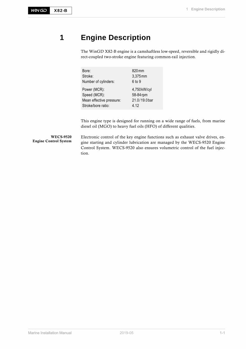
The WinGD X82-B engine is a camshaftless low-speed, reversible and rigidly di-rect-coupled two-stroke engine featuring common-rail injection.
This engine type is designed for running on a wide range of fuels, from marinediesel oil (MGO) to heavy fuel oils (HFO) of different qualities.
WECS-9520Engine Control System
Electronic control of the key engine functions such as exhaust valve drives, en-gine starting and cylinder lubrication are managed by the WECS-9520 EngineControl System. WECS-9520 also ensures volumetric control of the fuel injec-tion.
Bore:Stroke:Number of cylinders:
820 mm3,375mm6 to 9
Power (MCR):Speed (MCR):Mean effective pressure:Stroke/bore ratio:
4,750kW/cyl58-84 rpm21.0 / 19.0bar4.12

Marine Installation Manual 2019-05 1-2
1 Engine Description1.1 Power/speed range
X82-B
1.1 Power/speed range
Figure 1-1 Power / speed range of WinGD engines complying with IMO regulations
SM-0009
60502000
3000
4000
6000
8000
10 000
20 000
30 000
40 000
50 000
60 000
70 000
80 000
70 80 90 100 120 140 160 180Engine speed [rpm]
Output [kW]
X82-B
RT-flex58T-E
RT-flex50-ERT-flex50-D
X92X92-B
X82-D
X72-B
X72 X62-B
X62
X52
X40-B
X35-B
RT-flex50DF
X92DF
X82DF
X72DF
X62DF
X52DF
X40DF

Marine Installation Manual 2019-05 1-3
1 Engine Description1.2 Primary engine data
X82-B
1.2 Primary engine data
Table 1-1 Rating points
Bore x stroke: 820 x 3,375 [mm]
No. ofcyl.
R1 / R1+ R2 / R2+ R3 R4
Power [kW]
6 28,500 21,720 21,750 16,590
7 33,250 25,340 25,375 19,355
8 38,000 28,960 29,000 22,120
9 42,750 32,580 32,625 24,885
Speed [rpm]
All cyl. 76 / 84 76 / 84 58 58
Brake specific diesel fuel consumption (BSFC) [g/kWh] 100% power
All cyl. 164.8 / 162.8 157.8 / 157.8 164.8 157.8
Mean effective pressure (MEP) [bar]
All cyl. 21.0 / 19.0 16.0 / 14.5 21.0 16.0
Lubricating oil consumption (for fully run-in engines under normal operating conditions)
System oil approx. 9kg/cyl per day
Cylinder oil guide feed rate 0.6 g/kWh (for low sulphur content only)
BSFC data are quoted for fuel of lower calorific value 42.7MJ/kgAll other reference conditions refer to ISO standard (ISO 3046-1)
For BSFC the following tolerances are to be taken into account:+ 5 % for 100-85% engine power+ 6 % for 84-65 % engine power+ 7 % for 64-50 % engine power
The data given in this table refer to Standard tuning.

Marine Installation Manual 2019-05 1-4
1 Engine Description1.3 Components and sizes of the engine
X82-B
1.3 Components and sizes of the engine
Figure 1-2 Cross section
SM-0001
**
10
11
5
6
3
1
4
13
2
8
9
12
14
7
This cross section is considered as general information only.
123456789
1011121314
BedplateColumnCrankshaftBottom-end bearingsCrossheadConnecting rodCylinder coverCylinder linerPistonTurbocharging systemScavenging systemPuls lubricating system Supply unitRail unitDirection of rotation:clockwise as standard
*

Marine Installation Manual 2019-05 1-5
1 Engine Description1.3 Components and sizes of the engine
X82-B
Table 1-2 Overall sizes and masses
Design features
• Welded bedplate with integrated thrust bearing and main bearings designedas thin-shell white metal bearings
• Sturdy engine structure with stiff thin-wall box type columns and cast ironcylinder blocks attached to the bedplate by pre-tensioned vertical tie rods
• Semi-built crankshaft• Thin-shell aluminium bottom-end bearings• Crosshead with crosshead pin and single-piece large white-metal surface
bearings • Rigid cast iron cylinder monoblock• Special grey-cast iron cylinder liners, water cooled• Pulse Jet Lubricating System for high-efficiency cylinder lubrication• Cylinder cover of high-grade material with a bolted exhaust valve cage con-
taining a Nimonic 80A exhaust valve• Piston with crown, cooled by combined jetshaker oil cooling• Constant-pressure turbocharging system comprising high-efficiency turbo-
chargers and auxiliary blowers for low-load operation• Latest piston running concept for excellent piston running and extended
TBO up to 5 years• Supply unit: high-efficiency fuel pumps feeding the 1,000 bar fuel rail• Rail unit (common rail): common rail injection and exhaust valve actuation
controlled by quick-acting solenoid valves
No. ofcyl.
Length [mm]Piston dismantling height F1 a)
(crank centre - crane hook) [mm]
a) For F2 and F3 (piston removal with double-jib crane) see Table 3-1, 3-1.
Dry weight [t]
6 11,045
14,820
805
7 12,550 910
8 14,055 1,020
9 16,500 1,160

Marine Installation Manual 2019-05 1-6
1 Engine Description1.4 Engine tuning
X82-B
1.4 Engine tuning
As the Flex system (see section 1.5, 1-16) allows selection of injection and ex-haust valve control parameters — specifically variable injection timing (VIT) andvariable exhaust closing (VEC) — it can be used in special tuning options to op-timise the brake specific fuel consumption (BSFC) at individual engine loads.
Compliance withIMO Tier II and III
All tuning options comply with the IMO Tier II regulations for NOx emissions.For Tier III emission compliance, an exhaust gas treatment is required as de-scribed in 7.1.2 Selective catalytic reduction, 7-2.
Combinations of tuning and exhaust gas treatment methods can be obtainedfrom the GTD application.
Engine tuning options The following table gives an overview of the available tuning options with theirapplication and the required engine components. Tuning options need to bespecified at a very early stage of the project.
Table 1-3 Available tuning options
Data for these tuning options as well as de-rating and part-load performance dataare obtainable from the GTD application.
LowTV tuningsee section 1.4.8, 1-13
Low torsional vibration tuning (LowTV) can be applied when vibrations arisewith 6- and 7-cylinder engines (see 6.4 Torsional vibration, 6-6). This tuningmethod is combined with the available tuning options listed in Table 1-3.
Tuning Description Application Additional components
Standard tuning(Std)
High-load tuningWhen ship operates most of the time above 90% engine power
None
Delta tuning(Delta)
Part-load tuningWhen ship operates most of the time between 75 and 90 % engine power
None
Delta bypass tuning (DBT)
Part-load tuning with increased steam power production
For increased steam production between 50 and 100 % engine powerAllows reducing economiser size and minimising use of auxiliary boiler
Exhaust gas waste gate
Low load tuning(LLT)
Lowest possible BSFC in the operating range of 40-70% engine power
When ship operates most of the time at less than 75 % engine power
Exhaust gas waste gate
NOTE The tuning options must be predefined along with any engine order.

Marine Installation Manual 2019-05 1-7
1 Engine Description1.4 Engine tuning
X82-B
The following figure shows the BSFC curves for the available tuning options.
Figure 1-3 Typical BSFC curves in relation to engine power
BSFC data for Standard tuning are given in Table 1-1, 1-3.
BSFC data for the other tuning options can be obtained from the GTD applica-tion.
1.4.1 BSFC and NOx emission
The parameters controlling the fuel injection and exhaust valve timing are mod-ified with the engine tuning process. This ensures full tuning potential by suitablybalancing the design related limitations, BSFC and NOx.
There is a trade-off between BSFC and NOx emissions, where low BSFC resultsin high NOx emissions and vice versa. To ensure that IMO regulations are met,any associated increase in NOx emissions at specific load ranges must be com-pensated with a reduction in other load ranges.
SM-0482
152
154
156
158
160
162
164
166
168
20 30 40 50 60 70 80 90 100Engine power [%]
Fuel
con
sum
ptio
n [g
/kW
h]
Standard tuningDelta tuningDelta bybass tuningLow load tuning
NOTE The reliability of the engine is by no means impaired by applying a tuning option. All mechanical stresses and thermal loads are well within limits irrespective of engine tuning.

Marine Installation Manual 2019-05 1-8
1 Engine Description1.4 Engine tuning
X82-B
1.4.2 Standard tuning
Standard tuning is based on camshaft controlled engines. Although the Flextechnology seldom uses the Standard tuning option, it is still used as a referencefor the more advantageous Delta, DBT and LLT.
1.4.3 Delta tuning
The Delta tuning option is used to reduce the BSFC in the part-load range by tai-loring the firing pressure and the firing compression ratio of the engine to max-imum efficiency below 90% load. However, this is offset with a reduction inefficiency towards full load.
1.4.4 Delta bypass tuning
Delta bypass tuning is an engine tuning option designed to increase the exhaustgas temperature and steam production power (SPP), therefore allowing for a re-duction in auxiliary boilers use. This increase occurs at loads of more than 50%,while still complying with all existing emission legislations.
The following figure shows the SPP curves for the available tuning options.
Figure 1-4 Steam production power diagram
Besides the appropriately adjusted engine parameters related to fuel injectionand exhaust valve control, the DBT concept combines a specifically designed tur-bocharger system setup with the use of an exhaust gas waste gate (with a 50%power switch-point).
SM-0483
20 30 40 50 60 70 80 90 100
7000
8000
9000
6000
5000
4000
3000
2000
1000
0
Ste
am p
rodu
ctio
n po
wer
[kW
]
Engine power [%]
Standard tuningDelta tuningDelta bybass tuningLow load tuning

Marine Installation Manual 2019-05 1-9
1 Engine Description1.4 Engine tuning
X82-B
Exhaust gas waste gateDBT requires the fitting of an exhaust gas waste gate on the exhaust gas receiverbefore the turbocharger turbine (as seen in Figure 1-5). Exhaust gas passingthrough this valve bypasses the turbocharger, flowing to the main exhaust up-take.
Figure 1-5 Schematic functional principle of an exhaust gas waste gate
Working range The exhaust gas waste gate works as so:
• Below 50% engine power → Waste gate is closedAll exhaust gas flows into the turbocharger, this increases combustion pres-sure due to increased scavenge air pressure. As a consequence, the BSFC isreduced at low load compared to Delta tuning.
• Above 50% engine power → Waste gate is openA small percentage of the exhaust gas bypasses the turbocharger. This re-duces the mass flow rate of the turbocharger and the pressure of the scav-enge air. As a consequence, the exhaust temperature rises, allowing for anincrease in the steam production by means of an economiser.
SM-0318
Waste gate
Exhaust gas receiver
Scavenge air receiver
Engine
NOTE Since the exhaust gas waste gate is controlled by the scavenge air pressure, the indicated power is an approximation only.

Marine Installation Manual 2019-05 1-10
1 Engine Description1.4 Engine tuning
X82-B
Exhaust gas temperatureThe exhaust gas temperature with DBT is significantly higher than with Deltatuning; see Figure 1-6.
tEaT and tEbE In particular the tEaT (temperature exhaust gas after turbocharger) is approxi-mately 20°C higher at 70% engine power than with Delta tuning. This increaseis principally due to the slowing of the turbocharger. The open waste gate bypassreduces the mass flow rate of exhaust gas, resulting in a relative reduction of thescavenge air. The tEbE (temperature exhaust gas before economiser) is further increased(about 5°C) due to the mixing of exhaust gas from the waste gate bypass.As seen in Figure 1-6, the Delta tuning exhaust gas temperature does not changefrom the turbocharger to the economiser, as there isn’t this mixing of additionalbypassed exhaust gas.
Figure 1-6 Exhaust gas temperature increase with DBT
Steam productionIncreasing the exhaust gas temperature to produce more steam by way of theeconomiser is an efficient way of powering on-board steam services and usingwaste heat from main engine exhaust gas. In such condition DBT is the most economical tuning option; see Figure 1-4, 1-8. Within certain engine power ranges it may be possible to run without anyauxiliary boiler.
For the calculation of steam production through economiser the tEbE and therelevant mass flow shall be considered in the output of GTD application.
SM-0484
200
210
220
230
240
250
260
270
280
20 30 40 50 60 70 80 90 100Engine power [%]
Exh
aust
gas
tem
pera
ture
[o C]
TEaT Delta bypass tuningTEbE Delta bypass tuning
TEbE & TEaT Delta tuning

Marine Installation Manual 2019-05 1-11
1 Engine Description1.4 Engine tuning
X82-B
1.4.5 Low load tuning
The Low load tuning option is used to reduce the BSFC in the lower part-loadrange by optimising the engine and turbocharger to match for this low load oper-ation. However, this is offset with a reduction in efficiency towards full load.
Like DBT, LLT must consider engine parameters related to fuel injection and ex-haust valve control, combining a specifically designed turbocharger system setupwith the use of an exhaust gas waste gate (with a 85% power switch-point);see Exhaust gas waste gate, 1-9.
Working range The exhaust gas waste gate works as so:
• Below 85% engine power → Waste gate is closedAll exhaust gas flows into the turbocharger, this increases combustion pres-sure due to increased scavenge air pressure. As a consequence, the BSFC isreduced at low load.
• Above 85% engine power → Waste gate is openAs the turbocharger is optimised for lower part-load operation, at higherloads there is a surplus of available exhaust gas energy. This needs to be re-leased via the open waste gate to protect against turbocharger overspeed.
The higher scavenge air pressure in lower part load results in lower thermal loadand better combustion over the entire part-load range.
1.4.6 Steam production control (SPC)
The SPC system consists of an analogue controlled valve that enables theopening and closing of the exhaust gas waste gate (see Exhaust gas waste gate, 1-9), regulating the bypass of the turbocharger from the main engine. By in-creasing the bypass rate it reduces the mass flow rate of the turbocharger, this inturn increases the exhaust gas heat, which is used to produce steam as needed.
The SPC option can be applied to DBT and LLT, as the tuning options are al-ready equipped with an exhaust waste gate (see Exhaust gas waste gate, 1-9).Without the SPC this waste gate valve is either open or closed according to a setengine power percentage. The SPC constantly reacts, restricting the bypass flowto an optimum level. This is achieved by adjusting the valve according to realtime steam pressure values, enabling the SPC system to maintain a set steam re-quirement.
NOTE Since the exhaust gas waste gate is controlled by the scavenge air pressure, the indicated power is an approximation only.

Marine Installation Manual 2019-05 1-12
1 Engine Description1.4 Engine tuning
X82-B
The SPC is connected to and receives inputs from external systems, such as theexhaust gas economiser and auxiliary boiler control systems. The additional sys-tems work together with the engine to manage the valve. The system’s automa-tion and optimisation ensures steam requirement without over production, asdefined by the user. This is true regardless of the engine power (as seen in Figure1-7), where a minimum steam production requirement is set and maintainedacross the engine power range. With the availability of increased steam, the SPCis more efficient than switching on an auxiliary boiler, with overall fuel and costsaving.
Figure 1-7 Steam production of Delta bypass tuning with variable bypass
As well as a fully integrated steam production control system, user operatedwaste gate control is also available. Such an arrangement remains restricted towithin defined engine limitations, however does not ensure optimised efficiency.
Performance data referring to the use of the SPC in conjunction with WinGD en-gines can be obtained using the GTD application.
The SPC can also be considered in association with WHR (see section 1.4.7). Individual projects will be investigated on a case-by-case basis.
1.4.7 Waste heat recovery (WHR)
A waste heat recovery solution is available on an application basis. To providethe most energy-efficient solution WinGD offers customised technical supporton demand, considering various aspects of the specific installation like steampressure, single/double exhaust gas bypass, steam and power turbine configura-tion, combustion air suction, etc. (see 4.11 Waste heat recovery, 4-57).
SM-0477
20 30 40 50 60 70 80 90 100Engine power [%]
Ste
am p
rodu
ctio
n po
wer
[kW
] Delta bybass tuningDelta bybass tuning with variable bypass

Marine Installation Manual 2019-05 1-13
1 Engine Description1.4 Engine tuning
X82-B
1.4.8 Low torsional vibration tuning (LowTV)
If required LowTV tuning is applied to the X82-B, on the 6- and 7-cylinder en-gines, in many cases negating the need for a costly torsional vibration damper.
Figure 1-8 shows a comparison in regard to torsional vibration when LowTVtuning is applied. At a certain engine speed, the measured torsional vibration am-plitudes decreased by nearly 30%.
Figure 1-8 Vibration amplitudes - Achievements with default LowTV tuning
NOTE LowTV tuning does not impair the engine performance.
SM-0322
Am
plitu
de F
E [o ]
Without LowTV tuning
With LowTV tuning
20 30 40 50 60 70 80Speed [rpm]
0
0.2
0.4
0.6
0.8
1
1.2
1.4
1.6
1.8
-28%

Marine Installation Manual 2019-05 1-14
1 Engine Description1.4 Engine tuning
X82-B
1.4.9 Tuning for de-rated engines
The tuning options are applicable over the entire rating field as illustrated inFigure 1-9.
Figure 1-9 Application area for tuning options
SM-0485
R3
R4
R2+
R1+
R2
R1
Engine speed[%]
50 60 70 80 90 100
Engine power[%]
30
40
50
60
70
80
90
100
All tuning options within the whole
layout field applicable

Marine Installation Manual 2019-05 1-15
1 Engine Description1.4 Engine tuning
X82-B
1.4.10 Dual tuning
The WinGD 2-stroke engines can be built and certified with ‘dual tuning’, i.e.Delta tuning and LLT or DBT and LLT. Each tuning method has its own advantages in terms of specific fuel consump-tion or exhaust gas flow and temperatures.
Changeover betweentuning regimes
Changing over from one tuning to the other when the engine is in service is along-term consideration, since the following modifications are to be carried outon the engine:
• Exchange of turbocharger nozzle ring (and diffuser)• ECS software parameter change• Installation/removal of blind flange for exhaust gas bypass (not needed for
DBT and LLT)• Change of orifice size in exhaust gas bypass
An engine cannot be operated with both tuning regimes at the same time, asswitching from one tuning to the other when the engine is in operation is not inaccordance with the IMO MARPOL Annex VI NOx regulation. Since for NOxcertification the Technical Files and EIAPP certificates will be approved sepa-rately for each tuning, the NOx emissions need to be measured on the testbed forboth tuning regimes.
Considerations to bemade when choosing
dual tuning
The following must be considered before ordering an engine with dual tuning:• GTD ancillary system data must be selected for the tuning with higher re-
quirements concerning pump and cooler capacity.• The torsional vibration calculation (TVC) must be carried out for both tun-
ings. However, only the calculation for the tuning showing worse torsionalstresses in the shafting shall be submitted for Class approval.
• The engine interface drawings must correspond to the tuning method withexhaust gas bypass (LLT or DBT)
• The sea trial programme (engine related tests) must be discussed with theshipyard. It should be defined beforehand with which tuning the speed trialof the vessel is to be performed.

Marine Installation Manual 2019-05 1-16
1 Engine Description1.5 The Flex system
X82-B
1.5 The Flex system
The X82-B engine is equipped with WinGD’s common rail fuel injection tech-nology, allowing flexible fuel injection. The flexibility provided by this tech-nology is reflected in the naming Flex system.
Figure 1-10 Flex system parts
Major benefits • Adaptation to different operating modes• Adaptation to different fuels• Optimised part-load operation• Optimised fuel consumption• Precise speed regulation, in particular at very slow steaming• Smokeless operation at all engine loads• Benefits in terms of operating costs, maintenance requirement and compli-
ance with emissions regulations
SM-0174
2 3 4 5 6Cylinder No. 1 - n
Engine control system
Rail unit (common rail)Fuel
Supply unit
WECS9520

Marine Installation Manual 2019-05 2-1
2 General Engine Data2.1 Pressure and temperature ranges
X82-B
2 General Engine Data
Selecting a suitable main engine to meet the power demands of a given project in-volves proper tuning in respect of load range and influence of operating condi-tions which are likely to prevail throughout the entire life of the ship. This chapter explains the main principles in selecting a WinGD 2-stroke marinediesel engine.
2.1 Pressure and temperature ranges
Please refer to the document ‘Usual values and safeguard settings’, which isprovided by WinGD under the following link:Usual values and safeguard settings
For signal processing see also 5.6.2 Signal processing, 5-11.

Marine Installation Manual 2019-05 2-2
2 General Engine Data2.2 Engine rating field and power range
X82-B
2.2 Engine rating field and power range
2.2.1 Introduction
It is critical that a ship’s propulsion system is correctly matching the main enginecharacteristics to ensure reliable operation in a variety of conditions includingdesign and off design situations. The below sections outline the specifics to aid inthis process.
2.2.2 Engine rating field
The rating field shown in Figure 2-1 is the area of selectable engine design powerand engine design speed. In this area, the contracted maximum continuousrating (CMCR) of an engine can be positioned individually to give the desiredcombination of propulsive power and rotational speed. Engines within thislayout field are tuned for maximum firing pressure and best efficiency.
Figure 2-1 Engine rating field for X82-B
The rating field serves to determine the specific fuel consumption, exhaust gasflow and temperature, fuel injection parameters, turbocharger and scavenge aircooler specifications at the selected rating.
Percentage values The engine speed is given on the horizontal axis and the engine power on the ver-tical axis of the rating field. Both are expressed as a percentage [%] of the respec-tive engine’s nominal R1+ parameters. Percentage values are being used so thatthe same diagram can be applied to various engine arrangements.
SM-0160
50
60
70
80
90
100
60 70 80 90 100
Engine speed[%]
Engine power[%]
The contracted maximum continuous rating (Rx) may befreely positioned within the rating field for that engine
Rating linefulfilling a ship’spower requirementfor a constant speed
Nominal propeller characteristic (1)
Nominal propeller characteristic (2)
R1
R2
R3
R4
Rx1Rx2
R1+
R2+

Marine Installation Manual 2019-05 2-3
2 General Engine Data2.2 Engine rating field and power range
X82-B
Rating pointsThe rating points (R1, R1+, R2, R2+, R3, R4) for WinGD engines are the cornerpoints of the engine rating field (Figure 2-1, 2-2). The rating field is limited bytwo constant MEP (mean effective pressure) lines R1 — R3 and R2 — R4 and bytwo constant engine speed lines R1+ — R2+ and R3 — R4.
The point R1 represents the nominal maximum continuous rating (MCR).
Any rating point (Rx) can be selected within the entire rating field to meet the re-quirements of each particular project. Such rating points require specific engineadaptations.
2.2.3 Propeller diameter and influence of propeller revolutions
Influence of propellerrevolutions on the power
requirement
At constant ship speed and for a given propeller type, a lower propeller speedcombined with a larger propeller diameter increases the total propulsive effi-ciency. Less power is needed to propel the vessel at a given speed.
The relative change of required power in function of the propeller revolutionscan be approximated by the following relation:
Formula 2-1
where:
PXj ............ = propulsive power at propeller revolution nj
nj ............... = propeller speed corresponding with propulsive power PXj
α ............... = 0.15 for tankers and general cargo ships up to 10,000dwt, or= 0.20 for tankers and bulk carriers from 10,000 to 30,000dwt, or= 0.25 for tankers and bulk carriers larger than 30,000dwt, or= 0.17 for reefers and container ships up to 3,000 TEU, or= 0.22 for container ships larger than 3,000 TEU
This relation is used in the engine selection procedure to compare different en-gine alternatives and to select an optimum propeller speed within the selected en-gine rating field. Usually, the number of revolutions depends on the maximumpermissible propeller diameter.
Maximum propellerdiameter
The maximum propeller diameter is often determined by operational require-ments, such as:
• Design draught and ballast draught limitations• Class recommendations concerning propeller/hull clearance (pressure im-
pulse induced on the hull by the propeller)
The selection of a main engine in combination with the optimum propeller (effi-ciency) is an iterative procedure where also commercial considerations (engineand propeller prices) are playing an important role.
2 2
1 1
PX n
PX n
aæ ö÷ç ÷ç= ÷ç ÷÷çè ø

Marine Installation Manual 2019-05 2-4
2 General Engine Data2.2 Engine rating field and power range
X82-B
According to the above approximation, when a required power/speed combina-tion is known — for example point Rx1 in Figure 2-1, 2-2 — a CMCR line canbe drawn which fulfils the ship’s power requirement for a constant speed. Theslope of this line depends on the ship’s characteristics (coefficient α). Any otherpoint on this line represents a new power/speed combination, for example Rx2,and requires a specific propeller adaptation.
2.2.4 Power range
Propeller curves and operational pointsTo establish the proper propeller curves, it is necessary to know the ship’s speedto power response.
Determining power/pro-peller speed relationships
Normally, the curves can be determined by using full-scale trial results from sim-ilar ships, algorithms developed by maritime research institutes, or model tankresults. With this information and by applying propeller series, the power/speedrelationships can be established and characteristics developed.
The relation between absorbed power and propeller speed for a fixed pitch pro-peller (FPP) can be approximated by the following cubic relation:
Formula 2-2
where:
P .............. = propeller power
n .............. = propeller speed
3
CMCR CMCR
P nP n
æ ö÷ç ÷ç= ÷ç ÷÷çè ø

Marine Installation Manual 2019-05 2-5
2 General Engine Data2.2 Engine rating field and power range
X82-B
Figure 2-2 Propeller curves and operational points
Figure 2-2 outlines the various engine limits, propeller curves and margins re-quired for engine optimisation. By incorporating the margins listed below, thevarious operational points and subsequently the CMCR point can be deter-mined. For detailed descriptions of the various line limits refer to section 2.2.5, 2-7.
Sea trial powerThe sea trial power must be specified. Figure 2-2 shows the sea trial power to bethe power required for reaching service speed, marked as point A, on the pro-peller curve with a light running margin (Line 8).
Sea margin The increase in power to maintain a given ship’s speed achieved in calm weather(point A in Figure 2-2) under average service condition (point B) is defined as ‘seamargin’ (SM). This margin can vary depending on owner’s and charterer’s ex-pectations, routes, season and schedules of the ship.
The location of reference point A and the magnitude of the sea margin are part ofthe new building contract and are determined between shipbuilder and owner.Typically, the sea margin is specified in the range of 10 to 25% of the sea trialpower.
SM-0026
Contracted maximumcontinuous rating
CMCR (Rx)
Continuous service rating
Sea trial power
Ship speed [% service speed] Engine speed [% CMCR rpm]
Eng
ine
pow
er [%
CM
CR
pow
er]
EM
SM
LR
3 4
5 77 88
ABCEMLRSMLine 3Line 4Line 5Line 7Line 8
Point of contractual power and ship speed during sea-trialsHydrodynamic design point / Continuous service rating (CSR)Recommended point for adaptation of propeller pitch under sea-trial conditionEngine marginLight running marginSea marginMaximum engine speed limit for continuous operationMaximum engine overspeed limit during sea-trialsAdmissible torque limitNominal propeller characteristic curvePropeller curve with a light running margin
100
100 100
100Maximum continuous power
Continuous service power
Sea trial power
Ser
vice
spe
ed
Ser
vice
rpm
CM
CR
rpm
Sea
tria
l rpm
Sea
tria
l spe
ed
A
B C
A
B C

Marine Installation Manual 2019-05 2-6
2 General Engine Data2.2 Engine rating field and power range
X82-B
Light running marginThe light running margin (LR in Figure 2-2, 2-5) is the margin in propeller rev-olutions with a new ship (i.e. under sea-trial condition) to attain or maintain anypower up to 100% in future continuous service. An additional power/enginespeed allowance must be provided for shaft generator/PTO installations (see sec-tion 2.2.6, 2-10).
The magnitude of the margin is generally determined by the engine builder and/or the shipbuilder and varies with specific ship designs, speeds, dry-docking in-tervals and trade routes. Typically, the light running margin is specified in therange of 4 to 7%.
Continuous service rating (CSR = NOR = NCR)Point A represents the power and propeller speed of a ship operating at contrac-tual service speed in calm seas with a new clean hull and propeller. On the otherhand, the same ship at same speed under service condition with aged hull andunder average weather conditions requires a power/speed combination ac-cording to point B. In that case, B is the CSR point.
Engine margin (EM) / operational marginMost owners specify the contractual ship’s loaded service speed at 85 to 90%power of the contracted maximum continuous rating. Different selections arepossible. The remaining e.g. 10 to 15% power can then be used to catch up withdelays in schedule.This margin is deducted from the CMCR. Therefore, the 100% power line isfound by dividing the power at point B by the selected CSR power percentage,e.g. 85 to 90%. The graphic approach to find the level of CMCR is illustrated inFigure 2-2, 2-5.
Contracted maximum continuous rating (CMCR = Rx = SMCR)The contracted maximum continuous rating is the point obtained by applyingthe margins (SM and EM) to the propeller curves. The calculated CMCR pointcan be selected freely within the entire engine rating field.
NOTE It is the shipbuilder’s responsibility to determine a light running margin large enough so that the power range limits on the left side of the nom-inal propeller characteristic (Line 7) are not reached in any service con-dition (see Figure 2-3, 2-7).

Marine Installation Manual 2019-05 2-7
2 General Engine Data2.2 Engine rating field and power range
X82-B
2.2.5 Power range limits
Once an engine is optimised at CMCR (Rx), the working range of the engine islimited by the following border lines (refer to Figure 2-3).
Figure 2-3 Power range limits
Line 1:100% Torque Limit
Constant mean effective pressure (MEP) or torque line through CMCR from100% speed and power down to 96% speed and power.
Line 2:Overload Limit
Available for testbed operation and emergency operation according to SOLASRegulation II-1/3.6. It is a constant MEP line, reaching from 102.3% power and96% speed (point P07) to 110% power and 103.2% speed (point P08). P08 is thepoint of intersection between Line 7 and 110% power.
Line 3:Speed Limit
Maximum engine speed limit where an engine can run continuously. It is 104%of CMCR speed. For Rx with reduced speed (nCMCR ≤ 0.98nMCR) this limit canbe extended to 106% (Line 3a), while the specified torsional vibration limitsmust not be exceeded.
Line 4:Overspeed Limit
The overspeed range between 104% (106%) and 108% speed is only permissibleduring sea trials if needed to demonstrate, in the presence of authorised repre-sentatives of the engine builder, the ship’s speed at CMCR power with a lightrunning propeller. However, the specified torsional vibration limits must not beexceeded.
SM-0420
0
10
20
30
40
50
60
70
80
90
100
110
0 10 20 30 40 50 60 70 80 90 100 110Engine speed [% Rx]
Eng
ine
pow
er [%
Rx]
8
7
65
4
21P09
P07
P06
P05
P04
P03
P02
P01
P01P02P03
P04 (CMCR)P05P06P07P08P09
406096
100406096
103.2108
2036961002440
102.3110110
Breakpoints EngineSpeed [%Rx]
EnginePower [%Rx]
P08
9
13
33a

Marine Installation Manual 2019-05 2-8
2 General Engine Data2.2 Engine rating field and power range
X82-B
Line 5:Continuous Operation
Power Limit
Admissible power limit for continuous operation. The line is separated by thebreakpoints listed in Figure 2-3, 2-7. Line 5 is a curve defined by Formula 2-3 and is separated into five components toform the entire curve. Each component is governed by different coefficients.Refer to Table 2-1 for the individual coefficients.
Formula 2-3
where:
P ............... = selected engine power [kW]
PCMCR ....... = CMCR engine power [kW]
n ............... = selected engine speed [rpm]
nCMCR ....... = CMCR engine speed [rpm]
C2/C1/C0 .. = coefficients / constants
Table 2-1 Line 5 coefficients
The area formed by Lines 1, 3, 5 and 9 is the range within which the engineshould be operated. The area limited by Line 7, Line 9 and Line 3 is recommended for continuous op-eration. The area between Line 7 and Line 5 is reserved for acceleration, shallow waterand normal operational flexibility. If a main-engine driven generator (PTO) is in-stalled, then the operating characteristics of the engine will differ. Refer to sec-tion 2.2.6, 2-10 for further details regarding PTO characteristics.
Line 6:Transient Condition
Power Limit
Maximum power limit in transient conditions. The line is separated by the break-points listed in Figure 2-3, 2-7. Line 6 is a curve defined by Formula 2-3 and is separated into five components toform the entire curve. Each component is governed by different coefficients.Refer to Table 2-2, 2-9 for the individual coefficients.
Line no. Range (n /nCMCR) C2 C1 C0
Line 5 0.00 - 0.40 0.000 0.500 0.000
0.40 - 0.60 0.500 0.300 0.000
0.60 - 0.96 1.111 -0.067 0.000
0.96 - 1.00 0.000 1.000 0.000
1.00 - 1.08 0.000 0.000 1.000
2
2 1 0CMCR CMCR CMCR
P n nC C C
P n n
æ ö æ ö÷ ÷ç ç÷ ÷ç ç= + +÷ ÷ç ç÷ ÷÷ ÷ç çè ø è ø

Marine Installation Manual 2019-05 2-9
2 General Engine Data2.2 Engine rating field and power range
X82-B
Table 2-2 Line 6 coefficients
The area above Line 1 and Line 9 is the overload range. It is only allowed to op-erate engines in that range for a maximum duration of one hour during sea trialsin the presence of authorised representatives of the engine builder.The area between Line 1, Line 5 and Line 6 (Figure 2-3, 2-7), called ‘servicerange with operational time limit’, is only applicable to transient conditions, i.e.sea trial or during emergency fast acceleration. The engine can only be operatedin this area for limited periods of time, in particular 1 hour per 24 hours.
Line 7:Nominal Propeller
Characteristic
Nominal propeller characteristic curve that passes through the CMCR point. The curve is defined by the 100% propeller law:
Formula 2-4
Line 8:Light Running
Propeller Curve
Propeller curve with a light running margin (typically between 4% and 7%). The curve is defined by the propeller law with a constant, governed by the se-lected light running margin (Formula 2-5).
Formula 2-5
where:
PLR ........... = propeller power at selected light running margin [kW]
PCMCR ....... = CMCR engine power [kW]
n ............... = selected engine speed [rpm]
nCMCR ....... = CMCR engine speed [rpm]
C .............. = constant
LR ............ = light running margin [%]
Line no. Range (n /nCMCR) C32 C1 C0
Line 6 0.00 - 0.40 0.000 0.600 0.000
0.40 - 0.60 0.330 0.468 0.000
0.60 - 0.96 1.110 0.000 0.000
0.96 - 1.032 0.000 1.066 0.000
1.032 - 1.08 0.000 0.000 1.100
3
CMCR CMCR
P nP n
æ ö÷ç ÷ç= ÷ç ÷÷çè ø
3LR
CMCR CMCR
P nC
P n
æ ö÷ç ÷ç= ´ ÷ç ÷÷çè ø
( )3
1
1C
LR=
+

Marine Installation Manual 2019-05 2-10
2 General Engine Data2.2 Engine rating field and power range
X82-B
Line 9:CMCR power
Maximum power for continuous operation.
Line 13:110% CMCR power
Constant power overload limit, available for testbed operation and emergencyoperation according to SOLAS Regulation II-1/3.6.
2.2.6 Power range limits with main-engine driven generator
The addition of a main-engine driven generator (PTO) alters the working rangeand operating characteristics of the engine. To generate the relevant curves, mul-tiple approaches can be used to incorporate the PTO limits. One such approachis outlined in the following.
Line 10:PTO Layout Limit
The PTO layout limit line (Line 10 in Figure 2-5, 2-11) defines the layout limitfor the power demanded by the propeller and PTO.Considering Line 10 as PTO layout limit provides the margin for normal powerload fluctuation and acceleration.
Figure 2-4 Power range limits for PTO operation
The breakpoints of Line 10 are listed in Figure 2-4. Line 10 is a curve defined byFormula 2-3, 2-8. It is separated into three components to form the entirecurve. Each component is governed by different coefficients. Refer to Table 2-3, 2-11 for the individual coefficients.
SM-0421
0
10
20
30
40
50
60
70
80
90
100
110
0 10 20 30 40 50 60 70 80 90 100 110Engine speed [% Rx]
Eng
ine
pow
er [%
Rx]
9
10
8
7
65
4
3
21
P10
P11
P12
P04
P04 (CMCR)P10P11P12
100406096
10013.228.892.2
Breakpoints EngineSpeed [%Rx]
EnginePower [%Rx]
3a
13

Marine Installation Manual 2019-05 2-11
2 General Engine Data2.2 Engine rating field and power range
X82-B
Table 2-3 Line 10 coefficients
Figure 2-5 Power range diagram of an engine with main-engine driven generator
Curve 1a in Figure 2-5 shows the power range with main-engine driven generator(PTO) 1). The latter can be a shaft generator (SG) which is either directlymounted on the intermediate shaft, or driven by a power take-off gear (PTO–G)mounted on the intermediate shaft or on engine free end side.
Due to the addition of constant nominal generator power over the major range ofengine load, the curve does not directly relate to a propeller characteristic.
Line no. Range (n /nCMCR) C2 C1 C0
Line 10 0.40 - 0.60 0.750 0.030 0.000
0.60 - 0.96 1.336 -0.321 0.000
0.96 - 1.00 0.000 1.941 - 0.941
1.00 - 1.08 0.000 0.000 1.000
1) without specification of installation type
SM-0029
40
50
60
70
80
90
100
110
120
80 90 100 110
EM/OM
SM
CMCR (Rx)
B
A
C
(1a)(2a)
(3a)
B’
PTO
Eng
ine
pow
er [%
Rx]
Engine speed [% Rx](1a) Nominal engine operation characteristic with PTO(2a) Nominal engine characteristic(3a) Nominal propeller characteristic without PTO
3 4
5
6
8
4-7% LR

Marine Installation Manual 2019-05 2-12
2 General Engine Data2.3 Operating conditions
X82-B
In the example of Figure 2-5, 2-11, the main-engine driven generator is as-sumed to absorb 5% of nominal engine power. The CMCR point is selected on apropeller curve which includes the PTO power demand at the CSR point. Thiscurve defines the nominal engine characteristic. This approach allows a practically unlimited flexible PTO operation, just limitedin the lower engine speed range by the PTO required minimum speed (as definedby the PTO device supplier) and the PTO layout limit Line 10, which is only rel-evant if a significant percentage of the installed engine power is utilised for PTO.
2.3 Operating conditions
The engine can be operated without any restrictions in the ambient conditionrange ‘winter’, as permissible by GTD, up to design conditions. Operation out-side these limits is possible, but further measures might need to be taken and thepower output might be limited. For project-specific support please contactWinGD.
2.3.1 Reference conditions
Engine performance data — like BSEC, BSEF, tEaT and others — are based onreference conditions. These conditions are specified in ISO standard 15550 (corestandard) and, for marine application, in ISO standard 3046 (satellite standard)as follows:
2.3.2 Design conditions
The capacities of ancillaries are specified according to ISO standard 3046-1(clause 11.4) following the International Association of Classification Societies(IACS) and are defined as design conditions:
Air temperature before blower:Engine room ambient air temperature:Coolant temperature before SAC:Barometric pressure:Relative humidity:
25 °C25 °C25 °C1,000 mbar30 %
Air temperature before blower:Engine room ambient air temperature:Coolant temperature before SAC:Barometric pressure:Relative humidity:
45 °C45 °C36 °C1,000 mbar60 %

Marine Installation Manual 2019-05 2-13
2 General Engine Data2.4 Ancillary system design parameters
X82-B
2.4 Ancillary system design parameters
The layout of the engine’s ancillary systems is based on the rated performance(rating point Rx, CMCR). The given design parameters must be considered inthe plant design to ensure a proper function of the engine and its ancillary sys-tems:
The engine power is independent of ambient conditions as found in marine ap-plications. The cylinder water outlet temperature and the oil temperature beforeengine are system-internally controlled and have to remain at the specified level.
Cylinder cooling water outlet temperature:Oil temperature before engine:Exhaust gas back pressure at rated power (Rx):
90°C45°C30mbar

Marine Installation Manual 2019-05 2-14
2 General Engine Data2.5 Electrical power requirement
X82-B
2.5 Electrical power requirement
Table 2-4 Electrical power requirement
No. cyl.
Power requirement [kW] Power supply
Auxiliary blowers a)
a) Minimal electric motor power (shaft) is indicated. Actual electric power requirement de-pends on size, type and voltage / frequency of installed electric motor. Direct starting orStar-Delta starting to be specified when ordering.
6 2 x 91
460 V / 60Hz7 2 x 113
8 2 x 113
9 2 x 142
Turning gear
6 11
460 V / 60Hz7 11
8 15
9 15
Engine Control System
6 1.4
230 V / 60Hz7 1.6
8 1.8
9 2.0
Propulsion Control System
all acc. to maker’s specifications 24 VDC UPS
Additional monitoring devices (e.g. oil mist detector, etc.)
all acc. to maker’s specifications

Marine Installation Manual 2019-05 2-15
2 General Engine Data2.6 GTD - General Technical Data
X82-B
2.6 GTD - General Technical Data
GTD is an application for the calculation and output of general technical datawhich are relevant for planning a marine propulsion plant. All data in this appli-cation are relating to the entire 2-stroke engine portfolio.
Engine performance data The GTD application allows calculation of the performance data (BSEC, BSEF,tEaT, etc.) for any engine power.
GTD output Beside the output of characteristic parameters in the whole rating field of an en-gine, the GTD application delivers data on the capacities of coolers, pumps,starting air bottles and air compressors. It also provides information on engineradiation, on the power requirement for ancillary systems, and outputs data suit-able for estimating the size of ancillary equipment. Furthermore, data about the available components and options depending onspecification and engine rating can be output. In addition to the standard outputfor ISO reference and design conditions, further operating conditions for whichinformation is required can be defined.
The GTD application is accessible on Internet at the WinGD Customer Portal orfrom the WinGD corporate webpage using the following link:https://www.wingd.com/en/media/general-technical-data
SM-0371

Marine Installation Manual 2019-05 3-1
3 Engine Installation3.1 Dimensions and masses
X82-B
3 Engine Installation
The purpose of this chapter is to provide information to assist in the installationof the engine. It is for guidance only and does not supersede current instructions.
3.1 Dimensions and masses
Figure 3-1 Engine dimensions
Table 3-1 Engine dimensions and masses
E
D
C
BA
G
F2 /
F3
F1
SM-0110
No. cyl.
Dimension in mm with a tolerance of approx. ±10 mmNet eng. mass a)
a) Without oil /water; net engine mass estimated according to nominal dimensions given in drawings, including turbocharger and SAC, pipingand platforms
A B C D E F1 b)
b) Min. height for vertical removal of piston
F2 c)
c) Min. height for vertical piston removal with double-jib crane
F3 d)
d) Min. height for tilted piston removal with double-jib crane
G [tonnes]
6 11,045
5,020 1,800 12,250
Dim
. dep
endi
ngon
TC
type
14,820 14,800 13,800 2,700
805
7 12,550 910
8 14,055 1,020
9 16,500 1,160
Min. capacity of bridge crane: 9,500kgMin. capacity of double-jib crane: 2 x 5,375 kg

Marine Installation Manual 2019-05 3-2
3 Engine Installation3.1 Dimensions and masses
X82-B
Project-specific dimensions and masses for main components to be requestedfrom engine builder.
3.1.1 Dismantling heights for piston and cylinder liner
Dimensions F1, F2, F3 in Figure 3-1, 3-1 and the corresponding table are forguidance only and may vary depending on crane dimension, handling tools anddismantling tolerances.However, please contact WinGD or any of its representatives if these valuescannot be maintained or if more detailed information is required.
For details see also drawings ‘Dismantling Dimensions’ (DG 0812) provided onthe WinGD corporate webpage under the following links:6-cyl. engine7-cyl. engine8-cyl. engine9-cyl. engine
3.1.2 Crane requirements
• An overhead travelling crane is to be provided for normal engine mainte-nance. (Crane capacity see Table 3-1, 3-1.)
• The crane is to conform to the requirements of the classification society.
NOTE The dimensions given in above table are not binding. For prevailing data refer to the relevant drawings, which are updated on a regular basis.
NOTE As a general guidance WinGD recommends a two-speed hoist with pendent control, which allows selecting either high or low speed, i.e. high speed 6.0m/minute, low speed 0.6-1.5m/minute.

Marine Installation Manual 2019-05 3-3
3 Engine Installation3.1 Dimensions and masses
X82-B
3.1.3 Thermal expansion at turbocharger expansion joints
Before making expansion pieces, enabling connections between the engine andexternal engine services, the thermal expansion of the engine has to be taken intoaccount. The expansions are defined (from ambient temperature 20°C to servicetemperature 55°C) as follows (see also Figure 3-2):
Figure 3-2 Thermal expansion, dim. X, Y, Z
Calculating thermalexpansion
Δx (Δy, Δz) = X (Y, Z) ⋅ α ⋅ ΔT
where:
Δx, Δy, Δz .. = thermal expansion
X, Y, Z ...... = distance as per relevant pipe connection plan and outline drawing
α .............. = 1.15 ⋅ 10-5 (coefficient of thermal expansion)
ΔT ............ = difference between service temp. and ambient temp. [°C]
Expansion Distance from ...
Transverse expansion (X) ... crankshaft centreline to centre of gas outlet flange
Vertical expansion (Y) ... bottom edge of bedplate to centre of gas outlet flange
Longitudinal expansion (Z) ... engine bedplate aft edge to centre of gas outlet flange
a) a)
Z
X
Y
a) Gas outlet flangeDimensions X, Y, Z SM-0054

Marine Installation Manual 2019-05 3-4
3 Engine Installation3.1 Dimensions and masses
X82-B
3.1.4 Content of fluids in the engine
Table 3-2 Fluid quantities in the engine
No. of cyl.
Lubricating oil Fuel oilCylinder cooling
waterFreshwater in
SAC a)
a) The given water content is approximate.
[kg] [kg] [kg] [kg]
6 2,650 105 2,300 1,120
7 3,000 105 2,700 1,120
8 3,400 105 3,050 1,200
9 3,850 181 3,400 1,200

Marine Installation Manual 2019-05 3-5
3 Engine Installation3.2 Engine outline views
X82-B
3.2 Engine outline views
The latest versions of the Engine Outline Drawings (DG 0812) are provided onthe WinGD corporate webpage under the following links:6-cyl. engine7-cyl. engine8-cyl. engine9-cyl. engine

Marine Installation Manual 2019-05 3-6
3 Engine Installation3.3 Platform arrangement
X82-B
3.3 Platform arrangement
3.3.1 Drawings
For platform arrangement see the links given in section 3.2, 3-5.
3.3.2 Minimum requirements for escape routes
The platforms shown in the relevant drawings are arranged in such a way as toensure safe escape routes for the crew. The minimum sizes required by the clas-sification societies are met.
Figure 3-3 Minimum requirements for headroom
Important! • The minimum sizes are to be taken into account when installing the engine.Special attention is to be given to the minimum distance between the ship’splatform and the lower engine platform, to ensure sufficient headroom (seeFigure 3-3).
• No dead ends may be created on the platforms by shipboard installations. Ifa dead end cannot be avoided, then a passage leading to the ship’s platformhas to be cleared before the dead end (distance from dead end: max.2,000mm).
See also the links to drawings in section 3.2, 3-5.
SM-0115
Ship’s platform
Lower platform
h = min. 2000 mm
600 mm
2000
mm
Reference frame

Marine Installation Manual 2019-05 3-7
3 Engine Installation3.4 Seating
X82-B
3.4 Seating
Engine seating is integral with the double-bottom structure and has to be of suf-ficient strength to support the weight of the engine, transmit the propeller thrustand withstand external couples and stresses related to propeller and engine reso-nance.
• Before any seating work can be performed, make sure the engine is alignedwith the intermediate propeller shaft.
• The longitudinal beams situated under the engine are to protrude from theengine room bulkhead by at least half the length of the engine, and aft as faras possible.
• The maximum allowable rake is 3° to the horizontal.
More details about engine seating can be found in the relevant Fitting Instruc-tion (DG 9710) on the WinGD corporate webpage under the following link: Fitting instruction - Engine seating and foundation
The latest version of the Marine Installation Drawing Set relevant for engineseating and foundation (DG 9710) is provided on the WinGD corporate web-page under the following link: MIDS

Marine Installation Manual 2019-05 3-8
3 Engine Installation3.5 Assembly
X82-B
3.5 Assembly
Engines may be installed as complete units or assembled from subassemblies inthe vessel, which may be afloat, in dry dock, or on the slipway.
3.5.1 Assembly of subassemblies
When the engine seating has been approved, the bedplate is lowered onto blocksplaced between the chocking points. The thickness of the blocks depends on thefinal alignment of the engine. Engine bedplates comprise fabricated sections withtapped holes for the jacking screws for engine alignment, and drilled holes toallow the passing of the holding-down bolts.
For checking thedimensions optical
devices or lasersmay be used
• Proceed with the preliminary alignment of the bedplate using wedges orjacking screws.
• Position the engine coupling flange to the intermediate shaft couplingflange.
• Ensure that the gap between both flanges is close to the calculated figuresand that both flanges are exactly parallel on the horizontal plane (max. de-viation 0.05mm).
• In the vertical plane, set the engine coupling flange 0.4-0.6mm higher thanthe calculated figures.
• Place the bearing caps in position and install the turning gear.• Ensure that the crankshaft deflections are as recorded in the ‘Engine As-
sembly Records’.• Check the bedplate level in longitudinal and diagonal directions with a taut-
wire measuring device provided by the engine builder.• Compare the readings with those recorded at works.
All final dimensions are to be witnessed by the representatives of the enginebuilder and the classification society, and recorded on appropriate log sheets.Crankshaft deflections at this stage are to correspond with the values recorded atworks.
• Temporarily secure the bedplate against unexpected movement.• Continue engine assembly by mounting the columns, cylinder blocks, run-
ning gear and scavenge air receiver.• Ensure that the bearing caps are loose before tensioning the tie rods.• Make periodic checks of the crankshaft deflections to observe and correct
any possible engine distortions.• Carry out careful adjustments of the wedges or the jacking screws to re-es-
tablish the preliminary alignment setting.
Once the engine assembly is completed, the final alignment and chocking is car-ried out with the vessel afloat.

Marine Installation Manual 2019-05 3-9
3 Engine Installation3.5 Assembly
X82-B
3.5.2 Installation of a complete engine
In the event that the engine is shipped in part deliveries and assembled at theshipyard before installation in the vessel, the shipyard is to undertake assemblywork in accordance with the demands of a representative of the engine builderand the classification society.
Please observe: • Engine mounting is to be carried out systematically.• The measurement readings have to be recorded on appropriate log sheets
and compared for correctness with the data in the ‘Engine Assembly Re-cords’ completed after test run in the manufacturer’s works.
• The engine is to be lowered onto blocks placed between the chockingpoints.
• The blocks are to be set in such a manner that the engine is slightly higherthan the final position, because less effort is required to lower the enginethan to raise it for alignment.
• For movements in the horizontal plane, both in lateral or longitudinal di-rections, the shipyard is to construct appropriate anchor points for the useof hydraulic jacks. Such movements have to be carried out with great careto avoid stresses and distortions to the bedplate.
• Regular crankshaft deflection readings have to be taken to observe the ef-fects, and any noticed deviation has to be rectified immediately.
3.5.3 Installation of an engine from assembled subassemblies
Subassemblies of the engine may be assembled ashore before installation in theship. One such assembly may comprise the following components:
• Bedplate• Main and thrust bearings• Crankshaft• Turning gear• Flywheel
The placing on blocks and alignment to shafting is analogue to that described insection 3.5.1, 3-8.
3.5.4 Installation of an engine in ship on slipway
Installing a complete or partially assembled engine in a ship under constructionon an inclined slipway is possible when careful attention is paid to the following:
• Large components suspended to take account of the incline• Tie rods centred and exactly perpendicular to the bedplate before tight-
ening.• Side, fore and aft arresters temporarily fitted to prevent the engine from
moving during launching of the ship• Additional temporary stays attached at upper platform level to steady the
engine during launching
NOTE • Strict attention is to be paid to the removal of anti-corrosion coatings and the subsequent application of rust preventing oil where required.
• The alignment tools are to be clean and ready for use.

Marine Installation Manual 2019-05 3-10
3 Engine Installation3.6 Engine and shaft alignment
X82-B
3.6 Engine and shaft alignment
Alignment and chocking of the engine should be carried out in accordance withour recommendations and is subject to test and inspection by the relevant classi-fication society.
Each stage of engine mounting is to be checked by qualified personnel and themeasurements cross-checked with the design figures. In the event of discrepan-cies the responsible parties (e.g. shipyard) are to advise the representative of theengine builder or WinGD.
3.6.1 Instructions and limits
Alignment can be done with either jacking screws or wedges.
For detailed alignment procedures refer to the latest version of Engine Align-ment Documents (DG 9709) provided on the WinGD corporate webpage underthe following link:Engine alignment
3.6.2 Tools
For Engine Alignment Tools (DG 9710-01) refer to the latest version of the re-spective drawings, which are provided on the WinGD corporate webpage underthe following link:Tool engine alignment
Marine Installation Manual 2019-05 3-11
3 Engine Installation3.7 Engine coupling
X82-B
3.7 Engine coupling
3.7.1 Design
The design of coupling bolts and holes for the flange connection of crankshaft/propulsion shafts as provided by design group 3114 is included in the engine de-sign approval by all major classification societies.
3.7.2 Machining and fitting of coupling bolts
• Before fitting the coupling bolts ensure that the mating flanges are concen-tric. Close the gap between the flanges completely by means of min. 4 tem-porary (non-fitted) bolts evenly distributed over the pitch hole diameter.
• Carry out drilling and reaming of engine and shaft couplings by means of acomputer controlled drilling machine or an accurately centred jig.
• In the case of non-matching holes or damaged holes apply joint cylindricalreaming to an oversize hole and then fit an individually machined bolt.
• The bolts have to be available for inserting in the holes on completion ofreaming. Each bolt is to be stamped with its position in the coupling, withthe same mark stamped adjacent to the hole. The following tolerances haveto be met:— bolt hole tolerance: H7— bolt tolerance: g6 (clearance fit)
• If there is any doubt that a fitted bolt is too slack or too tight, refer to theclassification society surveyor and a representative of the engine builder.
3.7.3 Tightening
• When tightening the coupling bolts it is essential to work methodically. Per-form crosswise tightening, taking up the threads on opposite bolts to hand-tight, followed by sequential torque tightening. Finally ensure the sameproper tightening for all bolts.
• Mark each bolt head in turn (1, 2, 3, etc.) and tighten opposite nuts in turnaccording to Tightening Instructions, making sure that the bolt head is se-curely held and unable to rotate with the nut.
• Lock castellated nuts according to Class requirements with either lockingwires or split pins. Use feeler gauges during the tightening process to ensurethat the coupling faces are properly mated with no clearance.
3.7.4 Installation drawing
The latest version of the drawing, relevant for the Connection Crank/PropellerShaft (DG 3114), is provided on the WinGD corporate webpage under the fol-lowing link:Connection crank/propeller shaft

Marine Installation Manual 2019-05 3-12
3 Engine Installation3.8 Engine stays
X82-B
3.8 Engine stays
Ship vibrations and engine rocking caused by the engine behaviour (see chapter6 Engine Dynamics, 6-1) are reduced by fitting lateral stays (see 6.2, 6-4).
The latest version of the Marine Installation Drawing Set relevant for enginestays (DG 9715) is provided on the WinGD corporate webpage under the fol-lowing link:MIDS

Marine Installation Manual 2019-05 3-13
3 Engine Installation3.9 Propulsion shaft earthing
X82-B
3.9 Propulsion shaft earthing
Electric current flows when a potential difference exists between two materials.The creation of a potential difference is associated with thermoelectric by the ap-plication of heat, tribo-electric between interactive surfaces, electrochemical whenan electrolytic solution exists, and electromagnetic induction when a conductingmaterial passes through a magnetic field.
Tracking or leakage currents are created in machinery by any of the above meansand — if they are not adequately directed to earth — can lead to component fail-ures, or in some cases result in fires and interference with control and monitoringinstrumentation.
3.9.1 Preventive action
Using earthing brushes in contact with slip rings and bonding the chassis bybraided copper wire are common ways of protecting electric machines. Whereoperating loads and voltages are comparatively low, the supply is isolated fromthe machine by an ‘isolating transformer’, often with handheld power tools. Thebuild specification dictates the earthing procedure to be followed and the classi-fication society is to approve the final installation. On vessels with star-wound alternators the neutral is considered to be earth, andelectrical devices are protected by automatic fuses.
Isolation ofinstrument wiring
Ensure that instrument wiring meets the building and classification society spec-ifications and that it is shielded and isolated to prevent induced signal errors andshort circuits. In certain cases large items of machinery are isolated from their foundations, andcouplings are isolated to prevent current flow, for instance when electric motorsare connected to a common gear box.
Retrospective fitting of earthing devices is not uncommon, but due considerationis to be given at design stage to adequate shielding of control equipment andearthing protection where tracking and leakage currents are expected. Magneticinduction and polarisation are to be avoided and degaussing equipment incorpo-rated if there is likely to be a problem.
3.9.2 Earthing device
Figure 3-4, 3-14 shows a typical shaft earthing device. The slip ring (1) is supplied as matched halves to suit the shaft, and secured bytwo tension bands (2) using clamps (12). The slip ring mating faces are finishedflush and butt jointed with solder. The brushes (4) are housed in the twin holder(3) clamped to a stainless steel spindle (6), and there is a monitoring brush (11) ina single holder (10) clamped to an insulated spindle (9). Both spindles are at-tached to the mounting bracket (8).
Conducting materialfor slip rings
Different combinations of conducting material are available for the constructionof slip rings. However, alloys with a high silver content are found to be efficientand hard wearing.

Marine Installation Manual 2019-05 3-14
3 Engine Installation3.9 Propulsion shaft earthing
X82-B
Figure 3-4 Shaft earthing arrangement
Position of earthing device on shaft
The earthing device has to be arranged as close as possible to the engine. In casea shaft generator/motor is installed, the earthing device has to be arranged onthe front side of the generator/motor, as close a possible to the engine.
Connectingelectric cables
The electric cables are connected as shown in Figure 3-5, 3-15 with the op-tional voltmeter. This instrument is at the discretion of the owner, but it is usefulto observe that the potential to earth does not rise above 100mV.
Typical arrangement for the propeller shaft
AA
123456789
101112
Slip ringTension bandsTwin holderBrushesConnection to the ship’s hullSteel spindleConnection to the voltmeterMounting bracketInsulated spindleSingle holderMonitoring brushClamps
View on ‘A’ (brush gear omitted)
SM-0058
9112
26
8
1
2
3
4
5 6
78
9
10
11
12
Section A-A

Marine Installation Manual 2019-05 3-15
3 Engine Installation3.9 Propulsion shaft earthing
X82-B
Figure 3-5 Shaft earthing with condition monitoring facility
Shaft monitoring
Propeller shaft
35 mm2
2.5 mm2
Insulated spindle
Hull/structure earthsto be separately connected
Slip ring condition voltmeter
SM-0056
PM+
PH-
50 mV
50250
250 mV
00
Shaft earth (hull)Additional terminals are providedas necessary for multi-shaft vessels.2.5 mm2

Marine Installation Manual 2019-05 3-16
3 Engine Installation3.10 Fire protection
X82-B
3.10 Fire protection
Fires may develop in areas such as scavenge air receiver/piston underside. Theengine is fitted with a piping system which leads the fire extinguishing agent intothe critical areas.
Where fire protection is required, the final arrangement of the fire extinguishingsystem is to be submitted for approval to the relevant classification society.
Extinguishing agents Various extinguishing agents can be considered for fire fighting purposes. Theyare selected either by the shipbuilder or the shipowner in compliance with therules of the classification society involved.
Steam as an alternative fire extinguishing medium is permissible for the scavengeair spaces of the piston underside, but may cause corrosion if countermeasuresare not taken immediately after its use.These countermeasures comprise:— Opening scavenge spaces and removing oil and carbon deposits— Drying all unpainted surfaces and applying rust protection (i.e. LO)
Table 3-3 Recommended quantities of fire extinguishing medium
NOTE If steam is used for the scavenge spaces, a water trap is recommended to be installed at each entry to the engine and assurance obtained that steam shut-off valves are tight when not in use.
Piston underside and scavenge air receiver
BottleNumber of cylinders
6 7 8 9
Volume [m3/cyl]
Mass [kg/cyl]
Size[kg]
Extinguishing mediumQuantity of fire
extinguishing bottles
11 40 45 Carbon dioxide (CO2) 6 7 8 8

Marine Installation Manual 2019-05 4-1
4 Ancillary Systems
X82-B
4 Ancillary Systems
Sizing the ancillary systems of the engine, i.e. for freshwater cooling, lubricatingoil, fuel oil, etc., depends on the contracted maximum engine power. If the ex-pected system design is out of the scope of this manual, then contact our repre-sentative or WinGD directly.
The GTD application provides data for estimating the size of ancillary equipmentand enables all engine and system data at any Rx rating within the engine ratingfield to be obtained. However, for convenience or final confirmation when opti-mising the plant, WinGD provides a computerised calculation service.
All pipework systemsto be flushed and
proved clean beforecommissioning!
All pipework systems and fittings are to conform to the requirements laid downby the legislative council of the vessel’s country of registration and the classifica-tion society selected by the owners. They are to be designed and installed to ac-commodate the quantities, velocities, flow rates and contents identified in thismanual, set to work in accordance with the build specification as approved bythe classification society and protected at all times from ingress of foreign bodies.

Marine Installation Manual 2019-05 4-2
4 Ancillary Systems4.1 Twin-engine installation
X82-B
4.1 Twin-engine installation
A vessel equipped with two separate main propulsion engines is considered atwin-engine installation. The installation of two WinGD 2-stroke engines allowscombining individual engine auxiliary systems.
In Table 4-1 WinGD provides information based on engines’ requirements. Class and other binding rules might overrule.
Table 4-1 Common and independent systems in twin-engine installations
System Independent system for each engine required
Common system possible
Remarks
LT cooling water system(see Figure 4-1, 4-3)
XPlease note: Parallel independent LT cooling water supply per engine to the scavenge air coolers from common LT cooling water circuit
XPlease note: Parallel independent LT cooling water supply per engine to the LO cooler and HT cooling water cooler from common LT cooling water circuit
HT cooling water system X
Main LO system X
Cylinder LO system(see Figure 4-2, 4-4)
X Day tanks for high- resp. low BN lubricating oil
X Rising pipe
X Separate distribution to each engine
Fuel oil systemX Feed system
X Booster circuit systems
Starting air system X
Control air X Supply system
Leakage collection system and washing devices
X
Exhaust gas system X
Engine venting pipes X

Marine Installation Manual 2019-05 4-3
4 Ancillary Systems4.1 Twin-engine installation
X82-B
Figure 4-1 LT cooling water system layout for twin-engine installation
SM-0191
1 Scavenge air cooler (SAC)2 HT cooling water cooler (engine 1)3 Lubricating oil cooler (engine 1)4 HT cooling water cooler (engine 2)5 Lubricating oil cooler (engine 2)6 Ancillary plants7 Central seawater cooler8 Temperature control valve9 Pumps
MainEngine 2
8 (set-point: 25 °C)
MainEngine 1
SAC
SAC
9
7
1
2
3 5
6
4
1

Marine Installation Manual 2019-05 4-4
4 Ancillary Systems4.1 Twin-engine installation
X82-B
Figure 4-2 Cylinder LO system layout for twin-engine installation
ME2
LUB
HIGH BNSERVICE TANK
LOW BNSERVICE TANK
ME1
LUB
ME – Main engineLUB – Lubricator
Min
. sta
tic h
eigh
t ac
cord
ing
to th
e sp
ecifi
catio
n in
MID
S
MM
MM
TRACE HEATING
CHANGEOVER VALVES(close to engine inlet)
SM-0193

Marine Installation Manual 2019-05 4-5
4 Ancillary Systems4.2 Cooling water system
X82-B
4.2 Cooling water system
The latest version of the Marine Installation Drawing Set relevant for thecooling water system (DG 9721) is provided on the WinGD corporate webpageunder the following link:MIDS
Freshwater coolingsystem
The main engine high-temperature (HT) and low-temperature (LT) cooling cir-cuits use freshwater as their cooling medium. As such, the HT and LT circuitsare integrated in the ship’s central freshwater cooling system.
Advantage of freshwaterover seawater
Freshwater cooling systems reduce the amount of seawater pipework and its at-tendant problems like scaling and corrosion. They provide for more efficientcooling as they allow a higher heat load than seawater, i.e. freshwater can beheated up to a higher temperature level and, along with a lower flow rate, allowsthe same cooling effect to be obtained. Thereby the overall running costs are re-duced.
Figure 4-3 shows the general installation principle.
Figure 4-3 Scheme of cooling water system
SM-0190
MainEngine
3
5 (set-point: 25 °C)74
6
SAC
1 2
1 Scavenge air cooler (SAC)2 HT cooling water cooler3 Lubricating oil cooler4 Ancillary plants
5 Automatic temp. control valve6 LT cooling water pump7 Central seawater cooler

Marine Installation Manual 2019-05 4-6
4 Ancillary Systems4.2 Cooling water system
X82-B
Separate HT circuitwith own cooler
The central freshwater cooling system runs with single-stage scavenge air coolerand separate HT circuit.
Figure 4-4 Separate HT cooling water circuit
To obtain the necessary data for this arrangement refer to the GTD application.
NOTE The HT circuit must be completely separate from the LT circuit. A dedi-cated HT water cooler is applied for heat exchange between HT and LT circuit without flow medium mixing.
SM-0106
HT circuit LT circuit
freshwater
Cylinder coolingwater cooler

Marine Installation Manual 2019-05 4-7
4 Ancillary Systems4.2 Cooling water system
X82-B
4.2.1 Central freshwater cooling system components
Low-temperature circuit
Seawatercirculating pump
The seawater circulating pump delivers seawater from the high and low seachests to the central seawater cooler.
Seawater strainer Simplex or duplex strainers to be fitted at each sea chest and arranged to enablemanual cleaning without interrupting the flow. The strainer perforations are tobe sized (no more than 6mm) such that the passage of large particles and debrisdamaging the pumps and impairing heat transfer across the coolers is prevented.
Central seawater cooler
Pump type Centrifugal
Capacity According to GTD: The seawater flow capacity covers the need of the engine only and is to be within a tolerance of 0 to +10% of the GTD value
Delivery pressure Determined by system layout
Working temperature According to ship specification
Cooler type Plate or tubular
Cooling medium Seawater
Cooled medium Freshwater
Design criterion Keeping max. 36 °C LT while seawater temp. is 32°C
Margin for fouling 10-15% to be added
Heat dissipation
Refer to GTDFreshwater flow
Seawater flow
Temperatures

Marine Installation Manual 2019-05 4-8
4 Ancillary Systems4.2 Cooling water system
X82-B
Temperature control The central freshwater cooling system is to be capable of maintaining the inlettemperature to the scavenge air coolers between 10 and 36°C. WinGD recom-mends that the controller is set to 25°C (set-point) as this has a positive influenceon the engine’s performance.
Freshwater pumps
Valve type Electrically or electro-pneumatically actuated three-way type (butterfly valves are not adequate) having a linear characteristic
Design pressure 5bar
Test pressure Refer to specification laid down by classification society
Press. drop across valve Max. 0.5bar
Controller Proportional plus integral (PI)
Temperature sensor According to control valve manufacturer's specification; fitted in engine outlet pipe
Pump type Centrifugal
Capacity According to GTD: The freshwater flow capacity covers the need of the engine only and is to be within a tolerance of 0 to +10% of the GTD value
Delivery head The final delivery head is determined by the layout of the system and must ensure that the inlet pressure to the scav-enge air coolers is within the range of summarised data
Working temperature According to ship specification

Marine Installation Manual 2019-05 4-9
4 Ancillary Systems4.2 Cooling water system
X82-B
High-temperature circuit
Cooling water pump
Automatictemperature control valve
Expansion tank To ensure that the required static head is applied to the cylinder cooling water(CCW) system, the expansion tank is to be fitted at least 3.5m above the highestengine air vent flange. The tank is to be connected by a balance pipe to the CCWpump suction.
Pump type Centrifugal, preferably with a steep head curve a)
a) As a guide, the minimum advisable curve steepness can be defined as follows:For a pressure increase from 100 to 107%, the pump capacity should not decrease by more than10%.
Pump capacity According to GTD: The flow capacity is to be within a tolerance of -10 to + 20% of the GTD value
Delivery head b)
b) The required pump delivery head (pp) can be calculated as follows:
[bar]
where:ΣΔp = system pressure lossesp0 = required pressure at engine inletdp = pressure drop between pump inlet and engine inleth/10.2 = constant
Determined by system layout
Working temperature 95°C
³SD ³ - +0 10.2p ph
p p p d
Valve type Electrically or electro-pneumatically actuated three-way type (butterfly valves are not adequate) having a linear characteristic
Design pressure 5bar
Test pressure Refer to specification laid down by classification society
Press. drop across valve Max. 0.5bar
Controller Proportional plus integral (PI); also known as proportional plus reset for steady state error of max. ±2 °C and transient condi-tion error of max. ±4 °C
Temperature sensor According to control valve manufacturer's specification; fitted in engine outlet pipe

Marine Installation Manual 2019-05 4-10
4 Ancillary Systems4.2 Cooling water system
X82-B
4.2.2 Cooling water treatment
Correct treatment of the cooling freshwater is essential for safe engine operation.Only demineralised water or condensate according to the following specificationmust be used as raw water. In the event of an emergency, tap water may be usedfor a limited period, but afterwards the entire cylinder cooling water system is tobe drained off, flushed, and recharged with demineralised water.
Table 4-2 Recommended parameters for raw water
Corrosion inhibitors In addition, the water used must be treated with a suitable corrosion inhibitor toprevent corrosive attack, sludge formation and scale deposits. (For details referto the chemical supply companies.) Monitoring the level of the corrosion inhib-itor and water softness is essential to prevent down-times due to component fail-ures resulting from corrosion or impaired heat transfer.
For further information about permissible cooling water additives please refer tothe document Cooling water and additives, which is provided on the WinGDcorporate webpage under the following link:Cooling water and additives
Parameter Value
Min. pH 6.5
Max. dH 10° (corresponds to 180 mg/l CaCO3) a)
a) In the case of higher values the water must be softened.
Max. chloride 80 mg/l
Max. sulphates 150 mg/l
NOTE No internally galvanised steel pipes should be used in connection with treated freshwater, since most corrosion inhibitors have a nitrite base.Nitrites attack the zinc lining of galvanised piping and create sludge.

Marine Installation Manual 2019-05 4-11
4 Ancillary Systems4.2 Cooling water system
X82-B
4.2.3 General recommendations for design
• The number of valves in the system must be kept to a minimum to reducethe risk of incorrect setting.
• Valves are to be locked in the set position and labelled to eliminate incorrecthandling.
• After the system commissioning is completed, it is prohibited to manuallyinterfere with the cooling water flow in different branches of the MEcooling water system by adjusting the valves or the orifice.
• Under normal operation of the cylinder cooling water system, the pump de-livery head and the total flow rate are to remain constant, even when thefreshwater generator is started up or shut down.
• The cylinder cooling water system is to be totally separated from steam sys-tems. Under no circumstances must there be any possibility of steam en-tering the cylinder cooling water system, e.g. via a freshwater generator.
• The installation of equipment affecting the controlled temperature of cyl-inder cooling water (CCW) is to be examined carefully before being added.Uncontrolled increases or decreases in CCW temperature may lead tothermal shock of engine components and scuffing of pistons. Thermalshock is to be avoided, and the temperature gradient of the cooling waterwhen starting and shutting down additional equipment is not to exceed twodegrees per minute (2°C/min) at engine inlet.
• The design pressure and temperature of all the component parts such aspipes, valves, expansion tank, fittings, etc. are to meet the requirements ofthe classification society.
4.2.4 Freshwater generator
A freshwater generator, using heat from the cylinder cooling system to distil sea-water, can be used to meet the demand for washing and potable water. The ca-pacity of the freshwater generator is limited by the amount of heat available,which in turn is dependent on the service power rating of the engine.
The latest version of the Concept Guidance for freshwater generator installation(DG 9721) is provided on the WinGD corporate webpage under the followinglink: Freshwater generator installation
NOTE It is crucial in the design stage to ensure that there are sufficient safe-guards to protect the main engine from thermal shock when the fresh-water generator is started.To reduce such risk, it will be of advantage to use valves (for instance butterfly valves), which are linked and actuated with a large reduction ratio, at the freshwater generator inlet and in the bypass line.

Marine Installation Manual 2019-05 4-12
4 Ancillary Systems4.2 Cooling water system
X82-B
4.2.5 Pre-heating
To prevent corrosive liner wear when not in service or during short stays in port,it is important that the ME is kept warm. Warming-through can be provided bya dedicated heater, using boiler raised steam or hot water from the diesel auxilia-ries, or by direct circulation from the diesel auxiliaries.
Pre-heating from cooling water systemsIf the requirement for warming-up is from the cooling water systems of the dieselauxiliaries, it is essential that the amount of heat available at normal load is suf-ficient to warm the main engine. If the main and auxiliary engines have a cooling water system which can becross-connected, it has to be ensured that, when the cross-connection is made,any pressure drop across the main engine does not affect the cooling water pres-sure required by the auxiliaries. If the cooling water systems are apart, then a dedicated heat exchanger is re-quired to transfer the heat to the main CCW system.
Pre-heating by direct water circulationUse of main cylindercooling water pump
If the main CCW pump is used to circulate water through the engine duringpre-heating, then the heater is to be arranged parallel with the CCW system, andon/off control is to be provided by a dedicated temperature sensor at the CCWoutlet of the engine. The flow through the heater is set by throttling discs, but notby valves.
Use of separatepre-heating pump
If the requirement is for a separate pre-heating pump, a small unit with 10% ofthe main pump capacity and an additional non-return valve between CCW pumpand heater are to be installed. In addition, the pumps are to be electrically inter-locked to prevent two pumps running at the same time.
Recommendedtemperature
The recommended temperature to start and operate the engine is 60°C at CCWoutlet. If the engine is started below the recommended temperature, enginepower must not exceed 80% of CMCR until the water temperature has reached60°C.
The ambient engine room temperature and warm-up time are key parameters toestimate the heater power capacity required to achieve the target temperature of60°C. The shipyard or ship designer should determine the ambient engine roomtemperature and the warm-up time (which may also be specified by the ship-owner) on the basis of their own experience.
Warm-up time The graph in Figure 4-5, 4-13 shows the warm-up time needed in relation tothe ambient engine room temperature to arrive at the heat amount required percylinder. The graph covers the warming-up of engine components per cylinder,taking also the radiation heat into account. The readable figure is then multiplied by the number of cylinders to show theheater capacity required for the engine.

Marine Installation Manual 2019-05 4-13
4 Ancillary Systems4.2 Cooling water system
X82-B
Figure 4-5 Pre-heating power requirement per cylinder
All figures are related to requirements of the engine and should only be used fora first concept layout of the heater capacity. However, during pre-heater selec-tion the shipyard or ship designer must also consider further aspects such as heatlosses in the external piping system, water volume inside the system, pipelengths, volume of ancillary equipment, etc.
SM-0051 Heating-up time [h]
App
rox.
eng
ine
heat
ing
dem
and
[kW
/cyl
]
0
20
40
60
80
120
100
140
160
180
200
0 6 12 18 24 30 36 42 48
Pre-heating and heat losses of piping system to be added0°C E/R temp.
5°C E/R temp.10°C E/R temp.(recommended for layout)20°C E/R temp.
30°C E/R temp.
recommendedpre-heating time range

Marine Installation Manual 2019-05 4-14
4 Ancillary Systems4.3 Lubricating oil systems
X82-B
4.3 Lubricating oil systems
The latest version of the Marine Installation Drawing Set relevant for the lubri-cating oil system (DG 9722) is provided on the WinGD corporate webpageunder the following link:MIDS
4.3.1 Lubricating oil requirements
The validated lubricating oils were selected in co-operation with the oil suppliers.In their respective product lines the products are considered as appropriate lubri-cants for the application indicated. WinGD does not accept any liability for the quality of the supplied lubricatingoil or its performance in actual service.
The validated cylinder and system oils are published in the document Lubricantsprovided on the WinGD corporate webpage under the following link:Lubricants
4.3.2 Main lubricating oil system
Lubrication of the main bearings, thrust bearings, bottom-end bearings, cross-head bearings, together with piston cooling, is carried out by the main lubricatingoil system. The main bearing oil is also used to cool the piston crown and to lu-bricate and cool the torsional and axial vibration dampers.
Figure 4-6 shows the general installation principle.
Figure 4-6 Scheme of lubricating oil system
SM-0205
5
1
2
6
3
MainEngine
1 Lubricating oil drain tank2 Lubricating oil pump3 Lubricating oil cooler4 Automatic temperature control valve5 Automatic lubricating oil filter, with5 sludge checker6 Crosshead lubricating oil pump
4(Set-point: 45 °C)

Marine Installation Manual 2019-05 4-15
4 Ancillary Systems4.3 Lubricating oil systems
X82-B
Lubricating oil pump Positive displacement screw pumps with built-in overpressure relief valves, orcentrifugal pumps (for pump capacities refer to GTD):
Lubricating oil cooler
Type: Positive displacement screw pump
The flow rate is to be within a tolerance of 0 to + 10% of the GTD value, plus:- back-flushing flow of automatic filter, if any- torsional vibration damper, if any
Type: Centrifugal pump The flow rate is to be within a tolerance of - 10 to + 10 % of the GTD value, plus: - back-flushing flow of automatic filter, if any- torsional vibration damper, if any
Delivery head The final delivery head to be determined is subject to the actual piping layout.
Working temperature 60 °C
Oil type SAE30, 50 cSt at working temperature; when sizing the pump motor the maximum viscosity to be allowed for is 400 cSt.
Type Plate or tubular
Cooling medium Freshwater
Cooling water flow Refer to GTD.
Cooling water temperature 36 °C
Heat dissipation Refer to GTD.
Margin for fouling 10-15 % to be added
Oil flow Refer to GTD.
Oil viscosity at cooler inlet 50 cSt at 60°C
Oil temperature at inlet Approx. 60 °C
Oil temperature at outlet 45 °C
Working pressure oil side 6 bar
Working pressure water side Approx. 3 bar

Marine Installation Manual 2019-05 4-16
4 Ancillary Systems4.3 Lubricating oil systems
X82-B
Full-flow filter The drain from the filter is to be sized and fitted to allow free flow into the lubri-cating oil drain tank. The output required for the main lubricating oil pump to ‘back-flush’ the filterwithout interrupting the flow is to be taken into account when estimating thepump capacity (see Lubricating oil pump, 4-15).
Booster pump forcrosshead lubrication
Type a)
a) Optional: change-over duplex filter designed for in-service cleaning, with differential pressure gaugeand high-differential pressure alarm contacts
Automatic back-flushing filter with differential pressure gauge and high-differential pressure alarm contacts.Designed to clean itself automatically using reverse flow or compressed air techniques.Back-flushing oil treatment by sludge checker.
Oil flow Refer to GTD.
Working viscosity 95 cSt, at working temperature
Working pressure 6 bar
Test pressure Specified by classification society
Diff. pressure, clean filter Max. 0.2 bar
Diff. pressure, dirty filter Max. 0.6 bar
Diff. pressure, alarm Max. 0.8 barNote: real operational settings could be less according to filter maker’s recommendation.
Mesh size Sphere passing max. 0.035 mm
Filter material Stainless steel mesh
Filter inserts bursting press. Max. 3 bar differential across filter
Type Positive displacement screw or gear types with built-in overpres-sure relief valves
Capacity According to GTD: The flow rate is to be within a tolerance of 0 to 10 % of the GTD value.
Delivery head Refer to GTD.
Working temperature Approx. 45 °C
Oil type SAE 30, 95 cSt at working temperature; when sizing the pump motor the maximum viscosity to be allowed for is 400 cSt.

Marine Installation Manual 2019-05 4-17
4 Ancillary Systems4.3 Lubricating oil systems
X82-B
System oil For WinGD X82-B engines designed with oil-cooled pistons, the crankcase oilsused as system oil are specified as follows:
• SAE 30• Minimum BN of 5.0mg KOH/g and detergent properties• Load carrying performance in FZG gear machine test method A/8, 3/90
according to ISO 14635-1, failure load stage 11 as a minimum 1)
• Good thermal stability• Antifoam properties• Good demulsifying performance
The consumption of system oil is given in Table 1-1, 1-3.
4.3.3 Flushing the lubricating oil system
For flushing of the lubricating oil system refer to the latest version of the relevantInstruction (DG 9722), which is provided on the WinGD corporate webpageunder the following link:Instruction for flushing - Lubricating oil system
4.3.4 Lubrication for turbochargers
For lubricating oil for turbochargers equipped with separate lubricating oil sys-tems the recommendations given by the supplier must be observed.
4.3.5 Cylinder lubricating oil system
Cylinder lubrication is carried out by a separate system, working with theonce-through principle. A hydraulically actuated dosage pump feeds cylinder lu-bricating oil to the surface of the cylinder liner through quills in the liner. The oilsupply rate is adjustable and metered to suit the age and running condition ofpiston rings and liners.
For cylinder lubricating oil consumption refer to Table 1-1, 1-3.
Cylinder oil For normal operating conditions, a high-alkaline marine cylinder oil of SAE 50viscosity grade with a minimum kinematic viscosity of 18.5cSt (mm2/s) at100°C is recommended. The alkalinity of the oil is indicated by its Base Number(BN)2).
Cylinder lubricants of intermediate BN (50 < BN < 60mg/KOH/g) may be usedif the performance is regularly monitored and the lubricating oil feed rate is ad-justed to avoid a low piston underside BN. Residual BN which is too low canlead to excessive corrosive wear and scuffing.
1) The FZG gear machines located at the FZG Institute, Munich/Germany shall be thereference test apparatus and will be used in the event of any uncertainty about test re-peatability and reproducibility.
2) The Base Number is expressed in mg KOH/g as determined by test method ASTMD2896.

Marine Installation Manual 2019-05 4-18
4 Ancillary Systems4.3 Lubricating oil systems
X82-B
Recommendedresidual BN
The following values are recommended when operating on fuel with a sulphurcontent in the range of 0.5 to 3.5% m/m:
• The safe piston underside residual BN to avoid piston ring and liner corro-sion is higher than 25mg KOH/g but lower than 50mg KOH/g
• The alert limit for piston underside residual BN to avoid excessive corro-sion is between 10 and 25 mg KOH/g
• The danger limit is less than 10mg KOH/g piston underside residual BNand is likely to lead to excessive corrosion and early piston ring and linerwear if not corrected. It often leads to scuffing, premature failure of pistonrings and excessive corrosive liner wear.
Base number ofcylinder lubricating oil
The base number (BN) of the cylinder lubricating oil must be selected dependingon the total sulphur content of the fuel burnt. The higher the sulphur content inthe fuel, the higher BN for cylinder lubricating oil is required.Consequently, for low-sulphur fuel operation, low BN cylinder lubricating oilneeds to be supplied, whereas high BN cylinder lubricating oil is required whenthe engine is running on HFO.
Alternatives to finishedcylinder oils
The cylinder lubricating oil can also be blended/mixed on board. Multiple con-cepts for blending/mixing cylinder oil on board are available.
The validated additives and oils which can be used for this purpose can be foundin the document Lubricants, which is provided on the WinGD corporate web-page under the following link:LubricantsFor additional information please contact the oil supplier.
Another solution to have the needed BN value available is to mix lubricating oilsof different BN values.
Service tank and storage tankThe arrangement of service tank and storage tank can be changed by locating thestorage tank in place of the service tank. If this arrangement is preferred, thestorage tank must be placed at the same height as the service tank to provide thenecessary head. Furthermore, the storage tank must be of similar design, with asloping floor.
Electrical trace heating for cylinder lubricating oil pipingThe cylinder lubricating oil piping on ship side shall be electrically trace heatedand insulated to ensure an oil temperature of approx. 40°C at main engine inlet.WinGD has introduced a trace heating cable and insulation for the ME internalcylinder LO piping and provided a power connection box on the engine. Theshipyards can arrange the trace heating cable on the piping on ship side and con-nect the cable to the ME power connection box. For details of the power connection box and trace heating cable please refer tothe drawings of the relevant design group.

Marine Installation Manual 2019-05 4-19
4 Ancillary Systems4.3 Lubricating oil systems
X82-B
4.3.6 Maintenance and treatment of lubricating oil
It is essential that engine lubricating oil is kept as clean as possible. Water andsolid contaminants held in suspension are to be removed using centrifugal sep-arators which operate in bypass to the engine lubricating system. Great care has to be taken of the separators and filters to ensure that they workcorrectly. The separators are to be set up as purifiers and completely isolatedfrom the fuel oil treatment systems; there must be no possibility of cross-contam-ination.
Oil separator
Oil samples To ensure that representative samples of lubricating oil can be taken, dedicatedsampling points (cocks) are provided on engine side. Such cocks need also to beinstalled on system side according to the relevant system proposal drawing inMIDS.
Type Self-cleaning centrifugal separator
Min. throughput capacity [l/h] Refer to GTD.
Rated separator capacity The rated or nominal capacity of the separator is to be ac-cording to the separator manufacturer’s recommendations.
Separation temperature 90-95 °C; refer to manufacturer’s instructions.

Marine Installation Manual 2019-05 4-20
4 Ancillary Systems4.3 Lubricating oil systems
X82-B
4.3.7 Drain tank
The engine is designed to operate with a dry sump: the oil returns from the bear-ings, flows to the bottom of the crankcase and through strainers into the lubri-cating oil drain tank. The drain connections from the crankcase to the drain tankare arranged vertically.
The drain tank is to be located beneath the engine and equipped with the fol-lowing:
• Depth sounding pipe• Pipe connections for lubricating oil purifiers• Heating coil adjacent to pump suction• Air vents with flame protection
There is to maintain adequate drainage under sea conditions resulting in pitchingand rolling. The amount of lubricating oil required for an initial charge of thedrain tank is indicated in Figure 4-7. The total tank size is normally 5-10%greater than the amount of lubricating oil required for an initial filling.
Figure 4-7 Dimensioning and filling process of lubricating oil drain tank
NOTE The classification societies require that all drain pipes from the crank-case to the drain tank are taken as low as possible below the free sur-face of the oil to prevent aeration and foaming; they have to remain below the oil surface at all times. Strict attention has to be paid to this specification.
SM-0037
d
DN
h2h h1
Suction area Distance between suction pipe and bottom of tank
*1)
First filling
h1
h2
LO pump stopped
hx
h2
After systemcommissioning
LO pump stopped
Second filling
h1
h2
LO pump stopped LO pump in operation
h2
oper
atin
g le
vel
Engine in operation
Level after filling of external system.Volume and level in the lub. oil drain tank depend on capacity of pipes, coolers, filters, etc.The oil volume in tank contains part of the oil quantity which drains back when the pumpsare stopped.
*1)

Marine Installation Manual 2019-05 4-21
4 Ancillary Systems4.3 Lubricating oil systems
X82-B
Arrangement of verticallubricating oil drains
Figure 4-8 Arrangement of vertical lubricating oil drains for 6-cylinder engines
Inclination angles
NOTE The illustration above does not necessarily represent the actual config-uration or the stage of development, nor the type of your engine. For all relevant and prevailing information see MIDS drawings, 4-14.
SM-0038
1 2 3 4 5 6
*2)
*1) *1)
Driv
ing
end
Free
end
Proposal to determine final position in accordance with shipyard*1)Alternatively the oil drains may also be arranged symmetrically onport/fuel pump side.
*2)
Athwartships and fore-and-aft inclinations may occur simultaneously.
Trim (static) and pitching (dynamic)
Heel (static)
Rolling (dynamic)
SM-0065

Marine Installation Manual 2019-05 4-22
4 Ancillary Systems4.3 Lubricating oil systems
X82-B
Table 4-3 Minimum inclination angles for full operability of the engine (1)
NOTE The data in the following tables represent the state of data as of the year 2019 and earlier. If you want to obtain the latest data please ad-dress yourself to the relevant classification society.
Classification societies (overview see Appendix, Table 9-1, 9-1)
Year of latest update by ClassABS2019
BV2018
CCS2018
CRS2018
Main and auxiliary engine
Abbreviation 4/1/1/7.9 C/1/1/2.4 3/1/1/1.2.1 7/1/1.6/1.6.2
Heel to each side 15° 15° 15° 15°
Rolling to each side 22.5° 22.5° 22.5° 22.5°
Trim by the head a) 5° 5° 5° 5°
Trim by the stern a) 5° 5° 5° 5°
Pitching ±7.5° ±7.5° ±7.5° ±7.5°
Emergency sets
Abbreviation 4/1/1/7.9 C/1/1/2.4 3/1/1/1.2.1 7/1/1.6/1.6.2
Heel to each side 22.5° c) 22.5° 22.5° c) 22.5° c)
Rolling to each side 22.5° c) 22.5° 22.5° c) 22.5° c)
Trim 10° 10° 10° 10°
Pitching ±10° ±10° ±10° ±10°
Electrical installation
Abbreviation 4/1/1/7.9 C/1/1/2.4 4/1/2/1.2.1 7/1/1.6/1.6.2
Heel to each side 22.5° b) 22.5° b) c) 15° c) 22.5° b)
Rolling to each side 22.5° b) 22.5° b) c) 22.5° c) 22.5° b)
Trim 10° 10° b) 5° 10° b)
Pitching ±10° ±10° b) ±7.5° ±10° b)
a)Where the ship’s length exceeds 100 m, the fore-and-aft static angle of inclination may be taken as500/L degrees. (where L = length of ship in metres)
b)Up to an inclination angle of 45 degrees, switches and controls are to remain in their last set position as no undesired switching operations or operational changes may occur.
c)For ships carrying liquefied gases or chemicals the arrangement is to be such that the emergency power supply also remains operable with the ship flooded to a final athwartships inclination up to 30 degrees.

Marine Installation Manual 2019-05 4-23
4 Ancillary Systems4.3 Lubricating oil systems
X82-B
Table 4-4 Minimum inclination angles for full operability of the engine (2)
Classification societies (overview see Appendix, Table 9-1, 9-1)
Year of latest update by ClassDNV2016
DNV-GL2018
GL2016
IRS2018
KR2018
Main and auxiliary engine
Abbreviation 4/1/3/B 200 4/1/3/2.2/2.2.1 I-1-2/1/C/C.1.1 4/1/1/1.7/1.7.1 5/1/103./1.
Heel to each side 15° 15° 15° 15° 15°
Rolling to each side 22.5° 22.5° 22.5° 22.5° 22.5°
Trim by the head a) 5° 5° 5° 5° 5°
Trim by the stern a) 5° 5° 5° 5° 5°
Pitching ±7.5° ±7.5° ±7.5° ±7.5° ±7.5°
Emergency sets
Abbreviation 4/1/3/B 200 4/1/3/2.2/2.2.1 I-1-2/1/C/C.1.1 4/1/1/1.7/1.7.1 5/1/103./1.
Heel to each side 22.5° c) 22.5° c) 22.5° c) 22.5° c) 22.5° c)
Rolling to each side 22.5° c) 22.5° c) 22.5° c) 22.5° c) 22.5° c)
Trim 10° a) 10° a) 10° 10° 10°
Pitching ±10° ±10° ±10° ±10° ±10°
Electrical installation
Abbreviation 4/8/3/B 100 4/1/3/2.2/2.2.1 I-1-2/1/C/C.1.1 4/1/1/1.7/1.7.1 5/1/103./1.
Heel to each side 22.5° b) c) 22.5° b) c) 22.5° b) c) 22.5° b) c) 22.5° b) c)
Rolling to each side 22.5° b) c) 22.5° b) c) 22.5° b) c) 22.5° b) c) 22.5° b) c)
Trim 10° a) b) 10° a) b) 10° b) 10° b) 10° b)
Pitching ±10° b) ±10° b) ±10° b) ±10° b) ±10° b)
a)Where the ship’s length exceeds 100 m, the fore-and-aft static angle of inclination may be taken as 500/L degrees. (where L = length of ship in metres)
b)Up to an inclination angle of 45 degrees, switches and controls are to remain in their last set position as no undesired switching operations or operational changes may occur.
c)For ships carrying liquefied gases or chemicals the arrangement is to be such that the emergency power supply also remains operable with the ship flooded to a final athwartships inclination up to 30 degrees.

Marine Installation Manual 2019-05 4-24
4 Ancillary Systems4.3 Lubricating oil systems
X82-B
Table 4-5 Minimum inclination angles for full operability of the engine (3)
Classification societies (overview see Appendix, Table 9-1, 9-1)
Year of latest update by ClassLR
2018NK
2018PRS2019
RINA2018
RS2019
Main and auxiliary engine
Abbreviation 5/1/3/3.7 D/1.3.1/6 VI/1/1.6.1 C/1/1/2.4 VII/2/2.3
Heel to each side 15° 15° 15° 15° 15°
Rolling to each side 22.5° 22.5° 22.5° 22.5° 22.5°
Trim by the head a) 5° 5° 5° 5° 5°
Trim by the stern a) 5° 5° 5° 5° 5°
Pitching ±7.5° ±7.5° ±7.5° ±7.5° ±7.5°
Emergency sets
Abbreviation 5/1/3/3.7 D/1.3.1/6 VI/1/1.6.1 C/1/1/2.4 VII/2/2.3
Heel to each side 22.5° c) 22.5° b) c) 22.5° c) 22.5° c) 22.5° c)
Rolling to each side 22.5° c) 22.5° b) c) 22.5° c) 22.5° c) 22.5° c)
Trim 10° 10° b) 10° 10° 10°
Pitching ±10° ±10° b) ±10° ±10° ±10°
Electrical installation
Abbreviation 6/2/1/1.10 H/1/1.1.7 VIII/2/2.1.2.2 C/2/2/1.6 XI/2/2.1.2.2
Heel to each side 15° 15° c) 15° 22.5° b) 15° c)
Rolling to each side 22.5° 22.5° c) 22.5° 22.5° b) 22.5° c)
Trim 5° a) 5° a) 5° 10° b) 5° c)
Pitching ±7.5° ±7.5° ±10° ±10° b) ±10° c)
a)Where the ship’s length exceeds 100 m, the fore-and-aft static angle of inclination may be taken as 500/L degrees. (where L = length of ship in metres)
b)Up to an inclination angle of 45 degrees, switches and controls are to remain in their last set position as no undesired switching operations or operational changes may occur.
c)For ships carrying liquefied gases or chemicals the arrangement is to be such that the emergency power supply also remains operable with the ship flooded to a final athwartships inclination up to 30 degrees.

Marine Installation Manual 2019-05 4-25
4 Ancillary Systems4.4 Fuel oil system
X82-B
4.4 Fuel oil system
The latest version of the Marine Installation Drawing Set relevant for the fueloil system (DG 9723) is provided on the WinGD corporate webpage under thefollowing link:MIDS
Figure 4-9 shows the general installation principle.
Figure 4-9 Scheme of fuel oil system
SM-0300
MainEngine
HFO
1 HFO settling, storage and separation system2 LFO settling, storage and separation system3 Automatic fuel change over unit4 Low pressure feed pump5 Automatic self cleaning filter6 Flow meter
FM
LFO
PRV
HFO pipingLFO pipingCommon piping
5
57
4
8
10
6
31 2
11 9
LT Cooling water system
7 Fuel oil mixing unit8 High pressure booster pump9 Fuel oil endheater10 FW Fuel oil cooler11 Duplex filter

Marine Installation Manual 2019-05 4-26
4 Ancillary Systems4.4 Fuel oil system
X82-B
4.4.1 Fuel oil system components
Fuel oil feed pump
Formula for deliverygauge pressure
pv + 1 + Δp1 + Δp2 [bar]
where:
pv .............. = water vapour gauge pressure at the required system temp. [bar](see viscosity-temperature diagram in section 4.4.7, 4-39)
Δp1 ........... = max. pressure losses between feed pumps and mixing unit [bar]
Δp2 ........... = max. pressure change difference across the pressure regulatingvalve of the feed system between min. and max. flow
(see Pressure regulating valve, 4-27)
Example HFO of 700cSt at 50°C, required system temperature 145°C:
pv .............. = 3.2bar
Δp1 ........... = 0.5bar
Δp2 ........... = 0.6bar
Delivery gauge pressure = 3.2 + 1 + 0.5 + 0.6 = 5.3 bar
Type Positive displacement screw pump with built-in overpressure relief valve
Capacity According to GTD: The capacity is to be within a tolerance of 0 to + 20% of the GTD value, plus back-flushing flow of automatic filter, if any.
Delivery pressure The delivery pressure is to take into account the system pressure drop and prevent entrained water from flashing off into steam by en-suring that the pressure in the mixing unit is at least 1 bar above the water vapour pressure, and no lower than 3 bar. The water vapour pressure is a result of the system temperature and pressure for a given fuel type. Heavier oils need more heat and higher tempera-tures to maintain them at the correct viscosity than lighter oils.(Refer to the formula and example below.)
Electric motor The electric motor driving the fuel oil feed pump shall be sized large enough for the power absorbed by the pump at maximum pressure head (difference between inlet and outlet pressure), maximum fuel oil viscosity (700 cSt), and the required flow.
Working temp. Up to 90 °C
Fuel type Marine diesel oil and heavy fuel oil, up to 700 cSt at 50 °C

Marine Installation Manual 2019-05 4-27
4 Ancillary Systems4.4 Fuel oil system
X82-B
Pressure regulating valveTo prevent entrained water from flashing off into steam, the pressure regulatingvalve controls the delivery of the low-pressure feed pump by returning excessivesupply back to the pump’s suction side, ensuring that the discharge pressure is1 bar above the evaporation pressure of water. To avoid heating-up of the fuel byrecirculation, the return pipe is designed with cooling ribs.
The pressure regulating valve should have a flat steady-state characteristic acrossthe fuel oil recirculation flow range.
Mixing unitThe mixing unit equalises the temperature between the hotter fuel oil returningfrom the engine and the colder fuel oil from the service tank, particularly whenchanging over from HFO to MDO/MGO and vice versa.
Due to the small amount of fuel consumed, especially in part-load operation,only a small mixing unit is required. It is recommended that the tank contains nomore than approx. 100 litres. This is to avoid the changeover from HFO toMDO/MGO or vice versa taking too long.
For changing over between heavy fuel oil and marine diesel oil (MDO/MGO)and vice versa, as well as for operation on distillate fuel, refer to the separateConcept Guidance (DG 9723), which is provided on the WinGD corporate web-page under the following link:Operation on distillate fuels
Type Self- or pilot-operated which senses the upstream pressure to be maintained through an external line. It is to be pneu-matically or direct hydraulically actuated with an additional manual control for emergency operation. When using a pneumatic type, use a combined spring type to close the valve in case of air supply failure.
Maximum capacity According to GTD: Refer to feed pump capacity.
Minimum capacity Approx. 20 % of that of the fuel oil feed pump
Service pressure Max. 10bar
Pressure setting range 2-6bar
Inlet pressure change The inlet pressure may vary by up to 0.8bar depending on the flow in the range of 20 % to 100%.
Working temperature Up to 90°C
Fuel oil viscosity 100cSt, at working temperature (HFO 700 cSt at 50°C)

Marine Installation Manual 2019-05 4-28
4 Ancillary Systems4.4 Fuel oil system
X82-B
Figure 4-10 Mixing unit
Type Cylindrical steel fabricated pressure vessel as shown in Figure 4-10
Capacity Refer to GTD.
Dimensions See MIDS.
Service pressure 10bar
Test pressure According to classification society
Working temperature Up to 150°C
2
SM-0068
1
3
4
5
6
7
8
1
2
3
4
5
6
7
8
Outlet
Inlet, return pipe
Inlet from feed pump
Vent
Drain
Heating coil
Insulation
Mounting brackets

Marine Installation Manual 2019-05 4-29
4 Ancillary Systems4.4 Fuel oil system
X82-B
Fuel oil booster pumpThe fuel oil booster pump delivers the fuel to the engine via a fuel oil end heaterfor HFO operation.
End heaterOperates either temperature- or fuel oil viscosity controlled (default mode). The viscosity is measured by the viscosimeter.
Type Positive displacement screw pump with built-in overpressure relief valve
CapacityAccording to GTD: The flow rate is to be within a tolerance of 0 to +20 % of the GTD value, plus back-flushing flow of auto-matic filter, if any.
Inlet pressure Up to 6bar
Delivery headFinal delivery pressure according to actual piping layout.Refer to GTD.
Electric motor The electric motor driving the HP booster pump shall be sized large enough for the power absorbed by the pump at maximum pressure head (difference between inlet and outlet pressure), maximum fuel oil viscosity (600cSt), and the re-quired flow.
Working temperature Up to 150°C
Type Tubular- or plate type heat exchanger, suitable for heavy oils up to 700cSt at 50 °C
Heating source Steam, electricity, or thermal oil
Consumption of saturated steam
At 7bar gauge pressure [kg/h]:1.32 ⋅ 10-6 ⋅ CMCR ⋅ BSFC ⋅ (T1 - T2)where:— BSFC = brake specific fuel consumption at contracted
maximum continuous rating (CMCR)— T1 = temperature of fuel oil at viscosimeter a)
— T2 = temperature of fuel oil from service tank
a) The viscosity is maintained by regulating the fuel temperature after the end heater in that the visco-simeter monitors the fuel viscosity before the supply unit and transmits the signals to the heater con-trols.
Heating capacity [kW] 0.75 ⋅ 10-6 ⋅ CMCR ⋅ BSFC ⋅ (T1 - T2)
Working pressure Max. 12bar, pulsating on fuel oil side
Working temperature Up to 150°C, outlet temperature on fuel oil side

Marine Installation Manual 2019-05 4-30
4 Ancillary Systems4.4 Fuel oil system
X82-B
Diesel oil coolerFor diesel oil operation the fuel might need to be cooled to keep a minimum vis-cosity of 2cSt at engine inlet. A chiller unit is not required if the fuel propertiesare in line with the latest ISO 8217 specification; such a unit would only beneeded for off-spec fuels that are not supported by WinGD.
Type Tubular- or plate type heat exchanger, suitable for diesel oils
Cooling medium LT cooling waterAlternatively: glycol-water mixture delivered from chiller unit
Cooling capacity [kW]
where:Q [kW]BSFC [g/kWh]
P [kW]T1 [°C]T2 [°C]
= cooler heat dissipation at 100% engine load= specific fuel consumption at design conditions
and 100 % engine load= engine power at 100% CMCR= temp. of distillate fuel supplied to engine = temp. of distillate fuel required at engine inlet
Working pressure Max. 12 bar, pulsating on fuel oil side
( )1 26
0.34 25.65
10
BSFC P T TQ
⋅ ⋅ ⋅ - +=
SM-0187
From the engine
Distillate fuel supplyTo the engine T1T2 Cooler

Marine Installation Manual 2019-05 4-31
4 Ancillary Systems4.4 Fuel oil system
X82-B
Fuel oil filter
Two arrangements for the fuel oil filters can be applied in the fuel oil system, in-cluding:
• Arrangement ‘A’: (see Figure 4-11, 4-32)º a maximum 10 micron fine filter installed in either the feed ‘cold’ system
or booster ‘hot’ systemº a second, manually cleaned duplex filter of recommended maximum 25
micron installed upstream of the engine inlet booster system• Arrangement ‘B’: (see Figure 4-12, 4-35)
º a maximum 10 micron fine filter installed in the booster ‘hot’ system
Arrangement ‘A’(recommended)
A manually cleaned 25 micron (absolute sphere passing mesh size) duplex filteris installed in the booster system close to engine inlet. This arrangement is a bestpractice recommendation. However, a coarser filter is acceptable (arrangement‘B’ does not include secondary duplex filtration and lacks the indication of fueloil treatment system overall performance).A duplex filter is sufficient, as most particles are already removed by the finefilter outlined in option 1 or option 2 below.
Table 4-6 Specification of duplex filter in booster system
NOTE WinGD recommends arrangement ‘A’.
Working viscosity 10-20cSt required for HFO (13-17 cSt recommended)
Flow rate According to GTD. The capacities cover the needs of the engine only. If a filter of automatic back-flushing type is in-stalled, the feed and booster pump capacities must be in-creased by the quantity needed for back-flushing of the filter.
Service pressure Max. 12bar at filter inlet
Test pressure Specified by classification society
Permitted differential press. at 17 and 20cSt
— clean filter: max. 0.2bar— dirty filter: max. 0.6bar— alarm setting: max. 0.8barNote: real operational settings could be less according to filter maker’s recommendation.
Minimum bursting press. of filter insert
Max. 3bar differential across filter
Mesh size Recommended max. 25 micron (absolute sphere passing mesh)
Filter insert material Stainless steel mesh (CrNiMo)
Working temperature Up to 150°C

Marine Installation Manual 2019-05 4-32
4 Ancillary Systems4.4 Fuel oil system
X82-B
The maximum 10 micron fine filter can be installed in two locations:• Option 1:feed system• Option 2:booster system
The filter is used to protect the engine against serious damage. It captures the cat-alytic fines which were not removed by the fuel oil separator. In addition, thefilter provides a good indication of the separator’s efficiency.
Figure 4-11 Fuel oil filter arrangement ‘A’
NOTE Under consideration of the filter fineness an automatic filter with good self-cleaning performance must be selected.
SM-0206
MainEngine
HFO
1 HFO settling, storage and separation system2 LFO settling, storage and separation system3 Automatic fuel change over unit4 Low pressure feed pump5 Automatic self cleaning filter6 Flow meter
FM
LFO
PRV
HFO pipingLFO pipingCommon piping
5 (Note 1)
5 (Note 1)7
4
8
10
6
31 2
11 9
Only 1 automatic self cleaning filter to be installed: either before the engine inlet (hot side), orafter the low pressure feed pump (cold side)
LT Cooling water system
7 Fuel oil mixing unit8 High pressure booster pump9 Fuel oil endheater10 FW Fuel oil cooler11 Duplex filter
Note 1:

Marine Installation Manual 2019-05 4-33
4 Ancillary Systems4.4 Fuel oil system
X82-B
Option 1 10 micron fine filter in feed line:The maximum 10 micron (absolute sphere passing mesh size) fine filter is in-stalled in the ‘cold’ feed system. In this position the filter can be designed for alower flow rate compared to the booster system. However, higher resistance dueto higher fuel viscosity needs to be considered.
This filter position has the following advantage and disadvantage:
Table 4-7 Specification of automatic filter in feed system
Advantage Booster pump is protected against abrasive catfines
Disadvantage Engine is not optimally protected against booster pump wear particles
Working viscosity 100cSt, for HFO of 700 cSt at 50 °C
Flow rate According to GTD. The capacities cover the needs of the en-gine only. The feed pump capacity must be increased by the quantity needed for back-flushing of the filter.
Service pressure after feed pumps
10bar at filter inlet
Test pressure Specified by classification society
Permitted differential press. at 100cSt
— clean filter: max. 0.2bar— dirty filter: max. 0.6bar— alarm setting: max. 0.8barNote: real operational settings could be less according to filter maker’s recommendation.
Minimum bursting press.of filter insert
Max. 3bar differential across filter
Mesh size Max. 10micron absolute (sphere passing mesh)
Mesh size bypass filter Max. 25micron absolute (sphere passing mesh)
Filter insert material Stainless steel mesh (CrNiMo)

Marine Installation Manual 2019-05 4-34
4 Ancillary Systems4.4 Fuel oil system
X82-B
Option 2 10 micron fine filter in the booster circuit:The maximum 10 micron (absolute sphere passing mesh size) fine filter is in-stalled in the booster circuit close to engine inlet. The filter needs to be laid outfor a maximum working temperature of 150°C.
This filter position has the following advantage and disadvantage:
Table 4-8 Specification of automatic filter in booster system
Arrangement ‘B’ The 10 micron (absolute sphere passing mesh size) fine filter is installed in thebooster circuit close to engine inlet. The filter needs to be laid out for a maximumworking temperature of 150°C. With this arrangement, no indication is availableif the automatic filter fails.
Same filter specification as provided by Table 4-8.
Advantage Optimum engine protection from fuel oil catfines and other abrasive particles from system wear
Disadvantage Booster pump is not ideally protected against catfines
Working viscosity 10-20cSt required for HFO (13-17 cSt recommended)
Flow rate According to GTD. The capacities cover the needs of the engine only. If a filter of automatic back-flushing type is in-stalled, the feed and booster pump capacities must be in-creased by the quantity needed for back-flushing of the filter.
Service pressure Max. 12bar at filter inlet
Test pressure Specified by classification society
Permitted differential press. at 17 and 20cSt
— clean filter: max. 0.2bar— dirty filter: max. 0.6bar— alarm setting: max. 0.8barNote: real operational settings could be less according to filter maker’s recommendation.
Minimum bursting press. of filter insert
Max. 3bar differential across filter
Mesh size Max. 10micron absolute (sphere passing mesh)
Mesh size bypass filter Max. 25micron absolute (sphere passing mesh)
Filter insert material Stainless steel mesh (CrNiMo)
Working temperature Up to 150°C
NOTE Under consideration of the filter fineness an automatic filter with good self-cleaning performance must be selected.

Marine Installation Manual 2019-05 4-35
4 Ancillary Systems4.4 Fuel oil system
X82-B
Figure 4-12 Fuel oil filter arrangement ‘B’
4.4.2 Fuel oil system components for installations without HFO
The layout of the system without HFO is defined project-specifically. Significantsystem simplifications are possible. Please consult WinGD via its licensee.
4.4.3 Flushing the fuel oil system
For flushing of the fuel oil system refer to the latest version of the relevant In-struction (DG 9723), which is provided on the WinGD corporate webpageunder the following link:Instruction for flushing - Fuel oil system
SM-0214
MainEngine
LT Cooling water system
HFO
1 HFO settling, storage and separation system2 LFO settling, storage and separation system3 Automatic fuel change over unit4 Low pressure feed pump5 Automatic self cleaning filter
6 Flow meter7 Fuel oil mixing unit8 High pressure booster pump9 Fuel oil endheater10 FW Fuel oil cooler
FM
LFO
PRV
HFO pipingLFO pipingCommon
5
7
4
8
10
6
31 2
9

Marine Installation Manual 2019-05 4-36
4 Ancillary Systems4.4 Fuel oil system
X82-B
4.4.4 Fuel oil treatment
The latest version of the Concept Guidance for fuel oil treatment (DG 9723) isprovided on the WinGD corporate webpage under the following link:Fuel oil treatment
Settling tanksGravitational settling of water and sediment from modern heavy fuel oils is anextremely slow process due to the small difference in densities. The settling pro-cess is a function of the fuel surface area of the tank to the viscosity, temperatureand density difference. Heated large-surface area tanks enable better separationthan heated small-surface area tanks.
Service tanksDiesel oil service tanks are similar to heavy oil service tanks, with the possibleexception of tank heating, although this may be incorporated for vessels con-stantly trading in cold climates.Most of the service tank design features are similar to those of settling tanks,comprising a self-closing sludge cock, level monitoring device and remoteclosing discharge valves to the separator(s) and engine systems. The service tankis to be equipped with a drain valve arrangement at its lowest point, an overflowto the overflow tank, and recirculating pipework to the settling tank.
Water in fuel Due to condensation or coil leakage, water may be present in the fuel after theseparators. The recirculation pipe, which reaches to the lower part of the servicetank, leads the water into the settling tank. A pipe to the separators should beprovided to re-clean the fuel in the case of dirty water contamination. This lineshould be connected just above the drain valve at the service tank bottom.
Cleaning of fuel The fuel is cleaned either from the settling tank to the service tank or recircu-lating the service tank. Ideally, when the main engine is operating at CMCR, thefuel oil separator(s) should be able to maintain a flow from the settling tank to theservice tank with a continual overflow back to the settling tank. The sludge cockis to be operated at regular intervals to observe the presence of water, a signifi-cant indication for the condition of the separator(s) and heating coils.
Centrifugal fuel oil separatorsThere are two types of oil separators:
• Type 1 — Separators with gravity discs• Type 2 — Separators without gravity discs
NOTE Separators with gravity discs represent outdated technology and are therefore not supported by WinGD.

Marine Installation Manual 2019-05 4-37
4 Ancillary Systems4.4 Fuel oil system
X82-B
Separators withoutgravity discs
These separators are self-adjusting to the fuel properties and self-cleaning. Sep-arators without gravity discs operate as combined purifiers-clarifiers; thus waterand sediment separation is integrated in one unit. The manufacturers claim ex-tended periods between overhaul. Compared to the outdated separators withgravity discs the reliability is greatly improved, enabling unattended onboard op-eration. As it is usual to install a standby separator as a back-up, it is of advan-tage to use both units in parallel to improve the separation result.
For further details and information regarding the separators please refer to themanufacturer’s instructions.
Separation efficiency The separation efficiency is a measure of the separator's capability to removespecified test particles. The separation efficiency is defined as follows:
where:
n ............... = separation efficiency [%]
Cout ........... = number of test particles in cleaned test oil
Cin ............ = number of test particles in test oil before separator
Certified Flow Rate To express the performance of separators according to a common standard, theterm Certified Flow Rate (CFR) has been introduced. CFR is defined as the flowrate in litres/hour, 30 minutes after sludge discharge, at which the separation ef-ficiency is 85% when using defined test oils and test particles. CFR is defined forequivalent fuel oil viscosities of 380 and 700cSt at 50°C. More information can be found in the CEN document CWA 15375:2005 (E) ofthe European Committee for Standardization.
Throughput capacity The required minimum effective throughput capacity (litres/hour) of the separa-tors is determined by the formula 1.2 ⋅ CMCR ⋅ BSFC ⋅ 10-3 [litres/hour] as shownin the following example. The nominal separator capacity and the installationare to comply with the recommendations of the separator manufacturer. (The MDO separator capacity can be estimated using the same formula.)
Example • 9-cyl. engine• CMCR/R1+: 42,750kW• BSFC/R1+: 162.8g/kWh • Throughput: 1.2 ⋅ 42,750 ⋅ 162.8 ⋅ 10-3 = 8,352 litres/hour
Oil samples To ensure that representative samples of fuel oil can be taken, dedicated sam-pling points (cocks) are provided on engine side. Such cocks need also to be in-stalled on system side according to the relevant system proposal drawing inMIDS.
100 1 out
in
Cn
C
æ ö÷ç ÷ç= ⋅ - ÷ç ÷÷çè ø

Marine Installation Manual 2019-05 4-38
4 Ancillary Systems4.4 Fuel oil system
X82-B
4.4.5 Pressurised fuel oil system
The fuel is supplied from the heated heavy fuel oil service tank or the unheateddiesel oil service tank to the low-pressure feed system.
Fuel changeover For changing over from one fuel type to the other it was common to have asimple, manually operated three-way valve. This arrangement is not recom-mended any longer, as with the introduction of different Emission Control Areas(ECA), fuel changeover is quite frequently required, even at high engine load. (In the past it was needed in rare cases only, for instance due to maintenance orbefore stopping the engine, i.e. at relatively low loads.)
Automaticchangeover unit
Consequently, a well proven automatic changeover unit is nowadays recom-mended, which ensures:
• A maximum temperature gradient of 2K/min during changeover• A maximum viscosity of 20cSt• A minimum viscosity of 2cSt; this minimum limit is most challenging
during changeover from HFO to distillate fuel.Attention: not all changeover units guarantee keeping the minimum vis-cosity limit, as viscosity is not controlled.
• A best-practice automatic control of diesel oil cooler activation
4.4.6 Fuel oil specification
The validated fuel oil qualities are published in the document Diesel enginefuels provided on the WinGD Corporate Webpage under the following link:Fuel qualities

Marine Installation Manual 2019-05 4-39
4 Ancillary Systems4.4 Fuel oil system
X82-B
4.4.7 Fuel oil viscosity-temperature dependency
The fuel oil viscosity depends on its temperature. This dependency is shown asgraph in Figure 4-13.
Figure 4-13 Fuel oil viscosity-temperature diagram
SM-0215
-10 0 10 20 30 40 50 60 70 80 90 100 110 120 130 140 150 160
100 00050 000
20 000
10 000
5 000
2 000
1 000
500400300
200
100
5040
30
20
17
13
1098
7
6
5
4
333
35
40
45
60
70
80
100
150
200
300
4005006008001 000
1 5002 000
3 0004 0005 000
10 000
20 000
50 000
100 000
200 000400 000400 000
200 000
100 000
50 000
20 000
10 000
5 000
3 000
2 0001 500
1 000800600
400
300
200150
100
80
70
60
50
45
40
36
Sec
onds
Say
bolt
Uni
vers
al
Sec
onds
Red
woo
dN
o.1
Kin
emat
ic v
isco
sity
[mm
2 /s
(cS
t)]
-10 0 10 20 30 40 50 60 70 80 90 100 110 120 130 140 150 160 170
0 10 20 30 40 50 60 70 80 90 100 110 120 130 140 150 160 170 180 190 200 220 240 260 280 300 320 340
[°C]
[°F]
Recommended viscosity range for HFO before fuel injection pumps
Fuel oil temperature
Example To obtain the recommended viscosity before fuel injection pumpsa fuel oil of 380 mm2/s (cSt) at 50 °C must be heated up to 130 °C to 140 °C.
Oils can be pumped only with difficultyor not at all
30
60
100
30
60
100
180
600
50
Bunker Fuel Oil
Marine Diesel Oil
(typical)
Marine Gas Oil
(typical)
380380
Required viscosity range for HFO before fuel injection pumps
700 mm 2/s at 50 °C

Marine Installation Manual 2019-05 4-40
4 Ancillary Systems4.5 Starting and control air system
X82-B
4.5 Starting and control air system
The latest version of the Marine Installation Drawing Set relevant for thestarting air system (DG 9725) is provided on the WinGD corporate webpageunder the following link:MIDS
Compressed air is required for engine starting and control, exhaust valve airsprings, the washing plant for scavenge air coolers, and general services.
The starting and control air system shown in Figure 4-14 comprises two air com-pressors, two air receivers, and systems of pipework and valves connected to theengine starting air manifold.
Figure 4-14 Starting and control air system
SM-0034
PI PI
Drain Drain
Automaticdrain
DrainClean and dry instrument air,7...9 bar, supplied from board
Pipes on engine
Starting air feed pipesControl air pipesAncillary equipment pipes
Starting air receiver
Starting air compressor
Control air inletfor control system and air spring
Starting air inlet
Distribution pipewith automatic starting air shut-off valve
Main engine
Pipe connectionsPressure indicatorPI

Marine Installation Manual 2019-05 4-41
4 Ancillary Systems4.5 Starting and control air system
X82-B
4.5.1 Capacities of air compressor and receiver
The capacity of the air compressor and receiver depends on the total inertia (Jtot)of the propulsion system’s rotating parts.
• Total inertia = engine inertia + shafting and propeller inertia1):
• Engine inertia (Jeng): refer to GTD 2)
• Relative inertia:
4.5.2 System specification
Starting air compressors
The discharge air temperature must not exceed 90°C and the air supply to thecompressors is to be as clean as possible without oil vapour.
Starting air receivers
1) Propeller inertia includes the part of entrained water.2) The GTD application enables the capacities of compressors and air receivers to be op-
timised for the inertia of the engine and shaft line.
tot eng S PJ J J += +
totrel
eng
JJ
J=
Capacity Refer to GTD.
Delivery gauge pressure 30 bar
Type Fabricated steel pressure vessels with domed ends and inte-grated pipe fittings for isolating valves, automatic drain valves, pressure reading instruments and pressure relief valves
Capacity Refer to GTD.
Working gauge pressure 30 bar

Marine Installation Manual 2019-05 4-42
4 Ancillary Systems4.5 Starting and control air system
X82-B
4.5.3 Control air
Control air system supply Control air is supplied from the board instrument air supply system (see Figure4-14, 4-40) providing air at 8bar gauge pressure (within a range of 7.0-9.0bar).The air quality should comply with the compressed air purity class 2-4-2 ac-cording to ISO 8573-1 (2010-04-15).
Control air consumption With the development of engine technology the WinGD RT-flex and X/X-DFengines consume much less control air than conventional engines. The requiredcontrol air flow capacities are shown in Table 4-9. These data can be used forsizing the relevant engine external piping and facilities.
Table 4-9 Control air flow capacities
4.5.4 Service and working air
Service and working air for driving air powered tools and assisting in thecleaning of the scavenge air coolers is also provided by the board instrument airsupply system.
No. of cyl.
Control air flow capacity [Nm3/h]
6 14.4
7 16.8
8 19.2
9 21.6

Marine Installation Manual 2019-05 4-43
4 Ancillary Systems4.6 Leakage collection system and washing devices
X82-B
4.6 Leakage collection system and washing devices
The latest version of the Marine Installation Drawing Set relevant for theleakage collection and washing system (DG 9724) is provided on the WinGDcorporate webpage under the following link:MIDS
Sludge oil trap Dirty oil collected from the piston underside is led under a pressure of approx.2.8bar to the sludge oil trap and then to the sludge oil tank. The purpose of the sludge oil trap (see Figure 4-15) is to retain the large amountof solid parts contained in dirty oil and to reduce the pressure by means of an or-ifice or throttling disc fitted at its outlet, so that the sludge oil tank is under at-mospheric pressure. Design and dimensions of the sludge oil trap are given in the MIDS.
Figure 4-15 Sludge oil trap
SM-0035
Externalheating coil
Insulation
Drain to sludge oil tank
To sludge oil tank
A B
A BTest valve sludge oil levelTest valve air flow
AB

Marine Installation Manual 2019-05 4-44
4 Ancillary Systems4.6 Leakage collection system and washing devices
X82-B
From the piston rod stuffing box, dirty oil consisting of waste system oil, cylinderoil, metallic particles and small amounts of combustion products is led directly tothe sludge oil tank. Condensate from scavenge air is formed when the vessel is operating in a humidclimate. To avoid excessive piston ring and liner wear, the condensate is to becontinually drained from the scavenge air receiver.
4.6.1 Draining of exhaust uptakes
Engine exhaust uptakes can be drained automatically using a system as shown inFigure 4-16.
Figure 4-16 Arrangement of automatic water drain
4.6.2 Air vents
The air vent pipes of the ancillary systems have to be fully functional at all incli-nation angles of the ship at which the engine must be operational. This is nor-mally achieved if the vent pipes have an uninterrupted inclination of min. 5%.Such arrangement enables the vapour to separate into its air and fluid compo-nents, discharging the air to atmosphere and returning the fluid to its source.
SM-0081
1234
wl
Filling funnelPipe bracketTest cockCleaning doorMinimum water level
Sectional detail for view A
1
Ø108 x 5
1700
Ø368 x 8
1130
530
100
A
2
wl
3
4 Proposal fordesign and dimensions

Marine Installation Manual 2019-05 4-45
4 Ancillary Systems4.7 Exhaust gas system
X82-B
4.7 Exhaust gas system
For an optimised exhaust gas system the following velocities are recommendedfor pipes A, B and C shown in Figure 4-17:
Pipe A ....... = 40m/s
Pipe B ....... = 25m/s
Pipe C ....... = 35m/s
For the pipe diameters please refer to the GTD application.
Figure 4-17 Determination of exhaust pipe diameter
dB
dAdAdA dA
dA
*1) d
SM-0109
dC
The purpose for this by-pass is to allowengine operation after a turbocharger failure.During normal operation it is blinded off.The by-pass can be omitted if agreed with
*1)
Blinded portOpen port
Approx. 10 mm thick
*2)
can be designed as shown.*2)

Marine Installation Manual 2019-05 4-46
4 Ancillary Systems4.8 Engine room ventilation
X82-B
4.8 Engine room ventilation
4.8.1 Requirements
Engine room ventilation is to conform to the requirements specified by the legis-lative council of the vessel’s country of registration and the classification societyselected by the shipowners. Calculation methods for the air flows required for combustion and keeping themachinery spaces cool are given in the international standard ISO 8861 ‘Ship-building — Engine-room ventilation in diesel engined ships; Design require-ments and basis of calculations’.
Based on ISO 8861, the radiated heat, required air flow and power for the layoutof engine room ventilation can be obtained from the GTD application.
The final layout of the engine room ventilation is, however, at the discretion ofthe shipyard.
Figure 4-18 Direct suction of combustion air — main and auxiliary engine
Detail ASM-0101

Marine Installation Manual 2019-05 4-47
4 Ancillary Systems4.8 Engine room ventilation
X82-B
4.8.2 Air intake
If the combustion air is drawn directly from outside, the engine may operate overa wide range of ambient air temperatures as described in the following.
Operating temperatures between 45 and 5°CThe WinGD X82-B engine does not require any special measures, such aspre-heating the air at low temperatures, even when operating on heavy fuel oil atpart load, idling and starting up. The only condition which must be fulfilled isthat the water inlet temperature to the scavenge air coolers is no lower than25°C.
This means:• When combustion air is drawn directly from the engine room, no
pre-heating of the combustion air is necessary.• When combustion air is ducted in from outside the engine room and the air
suction temperature does not fall below 5°C, no measures need to be taken.
The central freshwater cooling system allows recovering the heat dissipated fromthe engine and maintains the required scavenge air temperature after the scav-enge air cooler by recirculating part of the warm water through the low-temper-ature system.
Operating temperatures between 5°C and GTD limits• For Standard and Delta tuning: not available.• For Delta bypass and Low load tuning: no further requirements are needed,
as the engine integrated exhaust gas bypass adjusts the scavenge air flow tothe engine.
Operating temperatures below GTD limitsPlease contact WinGD.
NOTE The scavenge air cooling water inlet temperature is to be maintained at min. +25°C. In the case of low-power operation this means that the scavenge air cooling water will have to be pre-heated. For that pur-pose, heat dissipation from other ancillary equipment, including lubri-cating oil and cylinder cooling water cooler, is utilised. Consequently no additional heater is required.

Marine Installation Manual 2019-05 4-48
4 Ancillary Systems4.8 Engine room ventilation
X82-B
Figure 4-19 Direct suction of combustion air (detail)
4.8.3 Air filtration
The necessity for installing a dust filter and the choice of filter type dependsmainly on the concentration and composition of dust in the suction air (see Table4-10, 4-50). Where suction air is expected to have a dust content of 0.5mg/m3
or higher — for instance on coastal vessels or vessels frequenting ports where theair has a high atmospheric dust or sand content — the air must be filtered beforeit enters the engine.
Main engineexhaust uptake
Diesel generatorexhaust uptake
Diesel generator
Air fans
Main engine, diesel generator and engine room air inlet with heavy weather spray deflectors, spray eliminators and filter banks.
Protective grill
Main engine
Detail - A
SM-0102

Marine Installation Manual 2019-05 4-49
4 Ancillary Systems4.8 Engine room ventilation
X82-B
Wear on piston ringsand cylinder liners
In the event that the air supply to machinery spaces has a dust content exceeding0.5mg/m3, which can be the case for ships trading in coastal waters, desert areasor transporting dust creating cargoes, there is a risk of increased wear to pistonrings and cylinder liners. The normal air filters fitted to the turbochargers are in-tended mainly as silencers but not to protect the engine against dust.
Figure 4-20 Air filter size (example for 8-cyl. engine)
NOTE WinGD advises to install a filtration unit for the air supplies to main en-gines and general machinery space on vessels regularly transporting dust creating cargoes, such as iron ore and bauxite.
70
80
90100
6560555045
40
35
30
25
2018
16
14
12
109
8
7
6
5
Req
uire
d fil
trat
ion
area
for p
ress
ure
drop
< 2
0 m
bar
5 7 8 9 10 14 16 18 20 25 30 35 40 45 50 60 706 12Engine power [MW]SM-0168
8X82-B: MCR = 38.0 MW
Filter surface [m2]
Inertia
l sep
arator
Roller
scree
n filte
r
Panel
filter
or
oil w
etted
filter
Oil wett
ed fil
ter an
d
pane
l filte
r in se
ries

Marine Installation Manual 2019-05 4-50
4 Ancillary Systems4.8 Engine room ventilation
X82-B
Table 4-10 Guidance for air filtration
Dust concentration in ambient air
Normal Normal shipboard requirement Alternatives necessary in very special circumstances
Most frequent particle sizes
Short period < 5 % of running time,< 0.5mg/m3
Frequently to permanently ≥ 0.5mg/m3
Permanently > 0.5mg/m3
> 5 μm Standard TC filter sufficientOil wetted or
roller screen filterInertial separator and
oil wetted filter
< 5 μm Standard TC filter sufficientOil wetted or panel filter
Inertial separator and oil wetted filter
---Normal requirement for the vast
majority of installations
These alternatives apply most likely to only very few extreme cases, e.g. ships carrying bauxite or similar dusty cargoes, or ships routinely trading along desert coasts.

Marine Installation Manual 2019-05 4-51
4 Ancillary Systems4.9 Piping
X82-B
4.9 Piping
4.9.1 Pipe connections
The latest versions of the Pipe Connection Plans (DG 8020) are provided on theWinGD corporate webpage under the following links:6-cyl. engine7-cyl. engine8-cyl. engine9-cyl. engine
4.9.2 Flow rates and velocities
For the different media in piping, WinGD recommends flow rates and velocitiesas stated in the document ‘Fluid velocities and flow rates’. Note that the given values are guidances figures only and that national standardsmay also be applied.
The latest version of the document ‘Fluid Velocities and Flow Rates’ (DG 9730)is provided on the WinGD corporate webpage under the following link:Recommended fluid flow rates and velocities

Marine Installation Manual 2019-05 4-52
4 Ancillary Systems4.10 PTO, PTI, PTH and primary generator applications
X82-B
4.10 PTO, PTI, PTH and primary generator applications
WinGD proposes various power take-off (PTO) and power take-in (PTI) ar-rangements that improve the efficiency and usability of the vessel’s propulsionchain. Some of the proposals are even suitable as power take-home devices(PTH), which enable the vessel to immobilise the main engine while staying ca-pable to move. Furthermore, the primary generator enables the vessel to generateelectric power by the main engine without running the propeller.
Depending on engine design the PTO solution can be applied either in the shaftline or at engine’s free end.
4.10.1 Requirements
After selecting the engine:1) Define the shaft power and the shaft speed.2) Estimate the electric power demand for propulsion purpose.3) Evaluate which of the PTO/PTI systems is the most suitable.4) Select suitable electrical components like frequency converter, etc.
4.10.2 Arrangements for PTO, PTI, PTH and primary generator
Figure 4-21, 4-53 illustrates the different arrangements for PTO, PTI, PTH andprimary generator.
NOTE All given alternatives are subject to a detailed project-specific study and definition. Please consult WinGD via their licensee.
NOTE The type of the PTO/PTI system has an influence on the execution of the main engine. Thus, changing from one system type to another is possible in the project stage but not after having ordered the engine.

Marine Installation Manual 2019-05 4-53
4 Ancillary Systems4.10 PTO, PTI, PTH and primary generator applications
X82-B
Figure 4-21 Arrangements for PTO, PTI, PTH
ACAC[7]
ACAC[8]
ACAC[1]
ACAC[9]
ACAC
[6]
ACAC[5]
ACAC
ACAC[2]
ACAC
ACAC[10]
ACAC[11][3]
12
ACAC[13]
ACAC[14]
ACAC[12][4]
12
CPP ClutchGearbox
Tunnelgear box 1
2
2-speedtunnelgear box
FPP
ACAC
GeneratorMachine
Torsional/
coupling
Frequency convertergrey:depending oncombinator orconstant speed mode
Torsionalelasticcoupling
bendingelastic
Clutch,thrust transmittingin open condition
SM-0200
ACAC[16]
ACAC[15]

Marine Installation Manual 2019-05 4-54
4 Ancillary Systems4.10 PTO, PTI, PTH and primary generator applications
X82-B
The following table itemises the arrangements corresponding to the numbers inFigure 4-21, 4-53.
Table 4-11 PTO / PTI / PTH arrangements for X82-B
4.10.3 Application constraints
The feasibility of project-specific PTO/PTI/PTH and primary generator needsto be studied in any case. An overview about impacts is given in Table 4-13, 4-55.
Table 4-12 Possible options for X82-B
[1] [2] [3] [4] [5] [6] [7] [8] [9] [10] [11] [12] [13] [14] [15] [16]
(X) O O O X O X O X O (X) O X O X O
X(X)
O
= the arrangement is possible= the arrangement may not be possible (too high nominal generator / el. motor torque due to too
low nominal engine speed and/or high generator / el. motor power)= the arrangement is not possible or plausible
NOTE In any case please check the application of arrangements for the selected engine with WinGD via their licensee.Project dependent options can also be considered.
Arrangements (see Figure 4-21, 4-53)
Option [1] [2] [3] [4] [5] [6] [7] [8] [9] [10] [11] [12] [13] [14] [15] [16]
PTO X -- -- -- X -- X -- X -- X -- X -- X --
PTI X -- -- -- X -- X -- X -- X -- X -- X --
PTH O -- -- -- O -- X -- O -- O -- O -- O --
Primary generator O -- -- -- O -- O -- (X) -- O -- O -- (X) --
Remarks a)
a) If the lowest torsional natural frequency is <1.5 Hz, special care has to be taken regarding possible engine speed fluctuations.
b)
b) With de-clutched propeller and pure generator operation, the minimum engine load requirement has to be obeyed.
a) b)
X(X)O--
= the option is possible= the option is possible, however uncommon= the option is not possible= the arrangement is not possible for X82-B

Marine Installation Manual 2019-05 4-55
4 Ancillary Systems4.10 PTO, PTI, PTH and primary generator applications
X82-B
Table 4-13 Influence of options on engineering
Extended TVC The added components have a considerable influence on the related project-spe-cific torsional vibration calculation. Proper case dependent countermeasuresneed to be taken depending on the results of the detailed TVC.
Misfiring detection Depending on the results of the TVC, a misfiring detecting device (MFD) mightbe needed to protect the elastic coupling and the gear-train (if present) from inad-missible torsional vibrations in case of misfiring.
Impact on ECS The PTO/PTI/PTH application has to be analysed via the licensee with thePropulsion Control System supplier and with WinGD for the Engine ControlSystem.
Shaft alignment study The added components can have an influence on the alignment layout. The shaftbearing layout has to be properly selected and adjusted to comply with the givenalignment rules.
Bearing loaddue to external load
The added components increase the bending moment and the related bearingloads. The bearing loads have to be checked for compliance with the given rules.
Dynamic conditionsdue to external load
The components attached to the free end have to be checked for any influence onthe axial and radial movements of the extension shaft caused by the dynamics ofthe engine.
Arrangements (see Figure 4-21, 4-53)
Engineering [1] [2] [3] [4] [5] [6] [7] [8] [9] [10] [11] [12] [13] [14] [15] [16]
Extended TVCX -- -- -- X -- X -- X -- X -- X -- X --
Misfiring detection(X) -- -- -- O -- O -- O -- (X) -- (X) -- (X) --
Impact on ECS(X) -- -- -- (X) -- (X) -- (X) -- (X) -- (X) -- (X) --
Shaft alignment study
(X) -- -- -- X -- X -- X -- (X) -- (X) -- X --
Bearing load due to external load
(X) -- -- -- X -- X -- X -- (X) -- X -- X --
Dynamic condition due to external load
O -- -- -- O -- O -- O -- X -- X -- X --
X(X)O--
= the arrangement has an influence on this engineering aspect= the arrangement might have an influence on this engineering aspect= the arrangement has no influence on this engineering aspect= the arrangement is not possible for X82-B

Marine Installation Manual 2019-05 4-56
4 Ancillary Systems4.10 PTO, PTI, PTH and primary generator applications
X82-B
4.10.4 Service conditions
The service condition depends on the selected PTO/PTI/PTH option. De-pending on engine type there are one or several cases, which are illustratedbelow.
Operation areaand prohibited area
The following illustration indicates how the engine generator unit can be oper-ated. The prohibited operation area is defined in section 2.2 Engine rating fieldand power range, 2-2.
Figure 4-22 FPP with mandatory frequency converter
100%
0%0% 100%
speed
power
powercurve
Valid for FPP with afrequency converter(mandatory).Applicable to options:1, 5, 7, 9, 11, 13
operation areaprohibited operation areaSM-0201

Marine Installation Manual 2019-05 4-57
4 Ancillary Systems4.11 Waste heat recovery
X82-B
4.11 Waste heat recovery
IntroductionThis section covers a number of auxiliary power arrangements for consideration.However, if any requirements are not fulfilled, contact our representative or con-sult WinGD directly. Our aim is to provide flexibility in power management andto reduce overall fuel consumption.
FunctionalityThe waste heat recovery (WHR) system uses exhaust energy with either a steamturbine, an exhaust gas power turbine, or a combination of the two, to generateelectrical power. The electrical power can be employed either in supplying ship-board services or in a shaft motor to boost propulsion when required through useof the PTI, see section 4.10, 4-52.
The power turbine begins to operate in the upper engine load range, making theWHR option a practical proposition for vessels that would typically operate at80% CMCR or higher, especially for high-powered engines employed on longvoyages.
Although initial installation costs for a heat recovery plant are relatively high, bymaximising the power used the WHR can regain costs through lower fuel con-sumption and lower exhaust gas emissions.
Figure 4-23 Heat recovery — typical system layout
SM-0449
Main Engine
Exhaust gaseconomiser
Exhaust powerturbine
Steam turbine
M/G
G
G
G
G
GMain Engine
Frequency control system
Aux. engine
Aux. engine
Aux. engine
Aux. engine
Ship service steam
Ship service power

Marine Installation Manual 2019-05 4-58
4 Ancillary Systems4.11 Waste heat recovery
X82-B
Benefits of waste heat recovery• The operator benefits from lower annual fuel costs.• The operator contributes to reducing emissions, such as CO2, NOx and
SOx.• With a WHR system the vessel‘s EEDI can be reduced.
These benefits provide the operator increased competitiveness in the freightmarket.
4.11.1 How to recover waste energy
The exhaust gas contains energy that was not converted to mechanical propul-sions energy and this is often wasted. However, some of this energy can be recov-ered by using a combination of the Rankine cycle (a thermodynamic cycleconverting heat into work) and turbocompound principles (pressured exhaust gasworking a turbine). This concept of high-efficiency WHR combined withWinGD common-rail low-speed engines allows up to 10% of the main engineshaft power to be recovered as electrical energy to be used to boost ship propul-sion and for shipboard services.
Energy is extracted from exhaust gas, scavenge air and cylinder jacket coolingwater and converted into electric power by means of an exhaust power turbine ora steam turbine, or a combination of both, operating a common or individualgenerator(s). This is seen in Figure 4-24.
Figure 4-24 WHR system
Exhaust power turbinePart of the exhaust gas delivered by the engine (up to 10%) bypasses the turbo-chargers through the exhaust power turbine. Even with reduced exhaust gasflow, today’s modern high-efficiency turbochargers are able to supply sufficientscavenge air to the engine as they have a surplus of efficiency within the upperload range.
The exhaust power turbine operates above approximately 55% engine load, withthe exhaust gas flow being controlled at the outlet of the exhaust gas manifold. Ifthe engine load is less than this, the gas flow is not branched to the turbine butchannelled solely to the turbochargers. As the exhaust power turbine has aboutthe same expansion ratio and efficiency as the engine’s turbochargers, the outlettemperature of the exhaust gas is about the same.
SM-0450
GeneratorMain Engine
Steamturbine
Exhaust powerturbine
Exhaust gaseconomiser
WHR plant

Marine Installation Manual 2019-05 4-59
4 Ancillary Systems4.11 Waste heat recovery
X82-B
Steam turbineThe steam turbine can be either a single or multi-stage pressure system. Nu-merous variants regarding steam production and operating concept may be in-volved in the WHR plant (see WHR steam systems, 4-62).
The exhaust gas heat energy generates steam for the turbine in the economiser byevaporating feed water. In a single pressure steam system the exhaust gas econo-miser consists of an evaporator and a superheater with a drum. In a dual-pressure(low/high) steam system, the economiser may contain various combinations ofevaporators, superheaters and LP + HP drums.
To increase the efficiency, the feed water is pre-heated by heat dissipation fromcylinder jacket water and scavenge air. Special engine tuning in combinationwith direct outside suction of scavenge air can be applied.
Feed water heating The feed water is heated to about 80°C with cylinder jacket cooling water. Fromhere the feed water is further heated up with scavenge air. Each scavenge aircooler module is equipped with a feed water heating section which is not neededfor scavenge air cooling. Cooling of the scavenge air is ensured even if the feedwater heating section runs dry.
The feed water temperature at the heater outlet varies with the engine load. Sincethe feed water temperature after heater may be higher than the water temperaturein the low-pressure steam drum, the temperature of the water being fed to thelow-pressure steam drum must be controlled to avoid steam flashing.The amount of feed water is equivalent to the total amount of steam generated inthe exhaust gas economiser.
Figure 4-25 Feed water heating
SM-0460
Cylinder jacketcooling water
Scavengeair cooler
Feed waterheater
to LP steam drum
to HP steam drum
Feed water pump

Marine Installation Manual 2019-05 4-60
4 Ancillary Systems4.11 Waste heat recovery
X82-B
4.11.2 Configuration concepts
Heat recovery concepts
The following figures show examples of different heat recovery concepts:• with steam turbine (Figure 4-26)• with power and steam turbines (Figure 4-27)• with power and steam turbines and PTI/PTO (Figure 4-28, 4-61)
Figure 4-26 Heat recovery with steam turbine
Figure 4-27 Heat recovery with power and steam turbines
Main Engine
Exhaust gaseconomiser
Steamturbine
G
G
G
G
GMain EngineAux. engine
Aux. engine
Aux. engine
Aux. engine
Ship service steam
Ship service power
SM-0445
Main Engine
Exhaust gaseconomiser
Exhaustpower
turbine
Steamturbine
G
G
G
G
GMain EngineAux. engine
Aux. engine
Aux. engine
Aux. engine
Ship service steam
Ship service power
SM-0446

Marine Installation Manual 2019-05 4-61
4 Ancillary Systems4.11 Waste heat recovery
X82-B
Figure 4-28 Heat recovery with power and steam turbines and PTI / PTO
Efficiency will likely be improved if the steam and power turbines drive separategenerators at variable speeds, individually synchronised to the grid. These tur-bines can be disconnected at any time if needed.
WHR with PTO/PTIProviding additional operational flexibility, the WHR system can be combinedwith a shaft motor system or a shaft generator system (the PTO/PTI applica-tions are further discussed in section 4.10, 4-52).
The PTI mode uses surplus electric power generated by the WHR system. ThePTO mode balances any electrical shortage with production from the shaft, pow-ered by the main engine and without the operation of generator sets. Table 4-14shows these different operating modes.
In general, the aim is to cover the power demand of the electrical ship servicewith a combination of the WHR system and PTO operation. This ensures a highoverall efficiency and a reduction in auxiliary engine running hours, resulting ina cost saving from reduced fuel and maintenance respectively.
Table 4-14 Operating modes
Main Engine
Exhaust gaseconomiser
Exhaustpower
turbine
Steamturbine
M/G
G
G
G
G
GMain Engine
Frequency control system
Aux. engine
Aux. engine
Aux. engine
Aux. engine
Ship service steam
Ship service power
SM-0447
PTI mode More electrical energy is generated by the WHR system than required for ship service. Surplus energy is supplied to the shaft motor to support the propulsion.If needed, the PTI could also be fed with electrical energy generated by the auxiliary en-gines to boost ship propulsion, e.g. in case fast acceleration is required.
PTO mode More electrical energy is required for ship service than generated by the WHR system. The engine drives the generator.
PTH mode (optional) The main engine is disconnected from the propeller shaft, while the thrust transmission to the engine is ensured. The ship is propelled by the PTI system with power supplied by auxiliary engines.

Marine Installation Manual 2019-05 4-62
4 Ancillary Systems4.11 Waste heat recovery
X82-B
WHR steam systems
The following figures show examples of different WHR steam systems:• Single-pressure steam system with evaporator and superheater (Figure 4-29)• Dual-pressure steam system with HP superheater (Figure 4-30)• Dual-pressure steam system with HP and LP superheaters (Figure 4-31, 4-63)
• Dual-pressure steam system with LP superheater and separate HP super-heater (Figure 4-32, 4-63)
Figure 4-29 Single-pressure steam system with evaporator and superheater
Figure 4-30 Dual-pressure steam system with HP superheater
~
H.P. service steam
SM-0456
Exhaust gas receiver
Scavenge air receiver
Engine
Steamturbine
H.P.Drum
G
Superheater
Cylinder jacketcooling water
Scavengeair cooler
Turbocharger
Evaporator
~
H.P. service steam
Ambientmax. 35°C
SM-0457
Exhaust gas receiver
Scavenge air receiver
Engine
Steamturbine
L.P.Drum
H.P.Drum
G
High-pressuresuperheater
Cylinder jacketcooling water
Scavengeair cooler
Turbocharger
WastegateHigh-pressure
evaporator
Low-pressureevaporator

Marine Installation Manual 2019-05 4-63
4 Ancillary Systems4.11 Waste heat recovery
X82-B
Figure 4-31 Dual-pressure steam system with HP and LP superheaters
Figure 4-32 Dual-pressure system with LP superheater & separate HP superheater
~
H.P. service steam
Ambientmax. 35°C
SM-0458
Exhaust gas receiver
Scavenge air receiver
Engine
Steamturbine
L.P.Drum
H.P.Drum
G
High-pressuresuperheater
Cylinder jacketcooling water
Scavengeair cooler
Turbocharger
WastegateHigh-pressure
evaporator
Low-pressureevaporator
Powerturbine
Low-pressuresuperheater
~G
~
H.P. service steam
Ambientmax. 35°C
SM-0459
Exhaust gas receiver
Scavenge air receiver
Engine
L.P.Drum
H.P.Drum
G
Low-pressuresuperheater
Cylinder jacketcooling water
Scavengeair cooler
Turbocharger
WastegateHigh-pressure
evaporator
Low-pressureevaporator
High pressuresuperheater
Steamturbine
NOTE All given alternatives are subject to a detailed project-specific study and definition. Please consult WinGD or their representative.

Marine Installation Manual 2019-05 5-1
5 Engine Automation5.1 DENIS-9520
X82-B
5 Engine Automation
WinGD provides a fully integrated Engine Control System named WECS-9520,which provides data bus connection to the Propulsion Control System (PCS) andthe Alarm and Monitoring System (AMS). The AMS is usually provided by theshipyard.
The leading suppliers of Propulsion Control Systems approved by WinGD en-sure complete adaption to engine requirements.
Figure 5-1 ECS layout
5.1 DENIS-9520
WinGD’s standard electrical interface is DENIS-9520, which is in line with ap-proved Propulsion Control Systems.
DENIS The DENIS (Diesel Engine CoNtrol and optImizing Specification)interface contains specifications for the engine management of allWinGD two-stroke marine diesel engines.
ECS The Engine Control System (ECS) takes care of all Flex system-spe-cific control functions, e.g. fuel injection, exhaust valve control,cylinder lubrication, crank angle measurement, and speed/loadcontrol. The system uses modern bus technologies for safe transmis-sion of sensor and other signals.
SM-0439
Propulsion Control System
Engine Control System(ECS)
Remote Control System
Engine Safety System
Alarm and Monitoring System
DENISSpecification
Electronic Speed Control System

Marine Installation Manual 2019-05 5-2
5 Engine Automation5.2 Concept
X82-B
Figure 5-2 Engine management and automation concept
5.2 Concept
The concept of DENIS-9520 offers the following features to shipowners, ship-yards and engine builders:
5.2.1 Interface definition
The WinGD interface defines the division of responsibilities between enginebuilder and PCS and AMS supplier, enabling the authorised suppliers to adapttheir systems to the common rail system engines. The data bus connection pro-vides clear signal exchange.
5.2.2 Approved Propulsion Control Systems
Propulsion Control Systems including Remote Control, Speed Control, Safetyand Telegraph Systems are available from suppliers approved by WinGD (seeTable 5-1, 5-4). This cooperation ensures that the systems fully comply withthe specifications of the engine designer.
DENISEngineControlSystem
EngineParts
DatasetCBM
ServiceAgreement
RemoteControl
AlarmSystem
SafetySystem
EngineControl
EngineOperation
Support
Spares &MaintenanceManagement
Support &Tools
SM-0281
MaintenanceVideo
ServiceBulletin
OperationManual

Marine Installation Manual 2019-05 5-3
5 Engine Automation5.3 DENIS-9520 Specification
X82-B
5.3 DENIS-9520 Specification
The DENIS-9520 Specification describes the signal interface between the EngineControl System and the PCS and AMS. It does not include any hardware, butsummarises all data exchanged and defines the control functions required by theengine. The DENIS-9520 Specification consists of two sets of documents:
5.3.1 DENIS-9520 Interface Specification
This signal interface specification is made available to engine builders and ship-yards. Besides the description of engine-built components for control, alarm andindication, the specification contains the following:
• List of alarm and display functions to be realised in the vessel’s AMS• Control diagram of the engine• Signal list including a minimum of functional requirements• Information related to the electrical wiring on the engine
5.3.2 DENIS-9520 Propulsion Control Specification
This document contains a detailed functional specification of the PropulsionControl System.
The intellectual property rights of this specification remain with WinGD. Hencethe document is licensed only to the partner companies of WinGD developingPropulsion Control Systems. These companies offer systems which are built ex-actly according to the engine designer’s specifications and are finally tested andapproved by WinGD.

Marine Installation Manual 2019-05 5-4
5 Engine Automation5.4 Propulsion Control Systems
X82-B
5.4 Propulsion Control Systems
Approved Propulsion Control Systems comprise the following independentsub-systems:
• Remote Control System (RCS)• Electronic Speed Control System• Safety System• Telegraph System
The Safety and the Telegraph Systems work independently and are fully opera-tive even with the RCS out of order.
RCS and ElectronicSpeed Control System
WinGD has an agreement with the marine automation suppliers listed in Table5-1 concerning development, production, sale and servicing of the RCS and theElectronic Speed Control and Safety Systems. All approved control systemslisted in this table comprise the same functionality specified by WinGD.
Table 5-1 Suppliers of RCS and Electronic Speed Control System
Modern Remote Control Systems consist of electronic modules and operatorpanels for display and order input in the Engine Control Room (ECR) and on thebridge (see Figure 5-3, 5-5). The different items normally communicate via se-rial bus connections. The engine signals described in the DENIS-9520 Specifica-tion are usually connected via terminal boxes on the engine with the electronicmodules placed in the ECR.
Supplier Remote Control System
Electronic Speed Control System
Kongsberg Maritime
Kongsberg Maritime ASP.O. Box 1009N-3194 Horten / Norway
[email protected] +47 81 57 37 00www.km.kongsberg.com
AutoChief 600 DGS C20
NABTESCO Corporation
NABTESCO corp.,Marine Control Systems Company1617-1, Fukuyoshi-dai 1-chomeNishi-ku Kobe, 651-22413 / Japan
[email protected] +81 78 967 5361www.nabtesco.com
M-800-V MG-800 FLEX
Wärtsilä Lyngsø Marine A/S
Wärtsilä SAM Electronics GmbHBehringstrasse 120D-22763 Hamburg / Germany
www.sam-electronics.de
Wärtsilä NACOS PCS Platinum
EGS2200RTfWärtsilä Lyngsø Marine A/S2, Lyngsø AlléDK-2970 Hørsholm / Denmark
[email protected] +45 45 16 62 00www.wartsila.com/lyngsoe

Marine Installation Manual 2019-05 5-5
5 Engine Automation5.4 Propulsion Control Systems
X82-B
Figure 5-3 Remote Control System layout
The electronic modules are in most cases built to be placed either inside the ECRconsole, or in a separate cabinet to be located in the ECR. The operator panelsare to be inserted in the ECR console’s surface.
SM-0438
Ship AlarmSystem
Local panel
Remote Control, Safety Controland Electronic Speed Control
Engine Control System
Engine room
Control room
Bridge wing (option) Bridge wing (option)Bridge
Remote Control System
WinGD

Marine Installation Manual 2019-05 5-6
5 Engine Automation5.4 Propulsion Control Systems
X82-B
5.4.1 PCS functions
Remote Control SystemMain functions • Start, stop, reversing
• Speed setting• Automatic speed program
Indications • The RCS is delivered with control panels for local, ECR and bridge control,including all necessary order input elements and indications, e.g. pushbuttons/switches and indication lamps or alternatively a respective dis-play.
• The following conditions in the engine are specified by the DENIS-9520standard to be indicated as a minimum:º In the control room:
- Starting air pressure- Engine speed- Revolutions- Operating hours- Load- Turbocharger speed- Scavenge air pressure in air receiver
º On the bridge:- Starting air pressure- Engine speed
º In addition to these indications, the RCS applied to the common railsystem engine includes displaying the primary values from the ECS, likefuel pressure, servo oil pressure, etc.
Electronic Speed Control SystemMain functions • Keeps the engine speed at the set-point given by the RCS.
• Sends fuel command to the ECS.• Limits fuel amount in function of charge air and measured speed for proper
engine protection.
To avoid compatibility problems and increased engineering effort, WinGD rec-ommends to apply RCS and Speed Control Systems of the same supplier.
Traditionally, the Electronic Speed Control System was considered a part of themain engine and was therefore usually delivered together with the engine. Withthe introduction of the ECS and DENIS-9520, the Electronic Speed ControlSystem is assigned to the PCS and shall therefore be delivered along with the cor-responding RCS and other components of the propulsion control package by theparty responsible for the complete PCS, i.e. in most cases the shipyard.
The details concerning system layout, mechanical dimensions of componentsand information regarding electrical connections have to be gathered from thetechnical documentation of the respective supplier.

Marine Installation Manual 2019-05 5-7
5 Engine Automation5.4 Propulsion Control Systems
X82-B
Safety SystemMain functions • Emergency stop
• Overspeed protection• Automatic shut-down• Automatic slow-down
Telegraph System• Order communication between the different control locations
Local manual control• Local manual control of the engine is performed from a control panel lo-
cated on the engine. The panel includes elements for manual order inputand indication for the Safety System, Telegraph System and ECS.
• The local control box with the local manual control panel is included in thepackage delivered by approved RCS suppliers.
ECR manual control panel• A manual control panel delivered together with the PCS and fitted in the
ECR console allows operating the engine manually and independently ofthe Remote Control System.
• The functions of the ECR manual control are identical to the control func-tions on the engine’s local control panel.
Options• Bridge wing control• Command recorder

Marine Installation Manual 2019-05 5-8
5 Engine Automation5.4 Propulsion Control Systems
X82-B
5.4.2 Recommended manoeuvring characteristics
The vessel speed is adjusted by the engine telegraph. Manoeuvring, e.g. forleaving a port, is available from full astern to full ahead. For regular full sea op-eration, the engine power can be further increased up to 100% CMCR power.
To protect the engine, any increase or decrease in power is limited by a rate ofchange, considering the warm-up respectively cool-down times. Therefore, de-pending on the magnitude of any change in power, it takes time to reach the re-quired engine output; see Table 5-2, 5-9.
Figure 5-4 Propulsion Control
A
AEH
D
ASTERN
STOP
SLOW
HALF
FULL
FULL
HALF
SLOW
DEADSLOW
DEADSLOW
SM-0099

Marine Installation Manual 2019-05 5-9
5 Engine Automation5.4 Propulsion Control Systems
X82-B
FPP manoeuvring stepsand warm-up times
The recommended manoeuvring steps and warm-up times for engine speed in-crease are indicated in Table 5-2. The engine speed-up/down program is includedin the ECS.
Table 5-2 Recommended manoeuvring steps and warm-up times for FPP
Load reduction is possible in half time of values mentioned in Table 5-2.
Figure 5-5 Manoeuvring speed/power settings for FPP installation
Manoeuvring position
Point Recommended CMCR speed [%]
Corresponding power [%]
Recommended warm-up time per load step [min]
Min. warm-up time per load step [min]
DEAD SLOW 1 25 - 35 1.5 - 4.5 0 0
SLOW 2 35 - 45 4 - 9 0 0
HALF 3 45 - 55 9 - 17 0.1 0.1
FULL 4 60 - 70 22 - 34 0.5 0.5
FULL SEA 1 5 92 78 45 34
FULL SEA 2 6 100 100 60 45
SM-0212
60 - 70
Recommended values forthe manoeuvring positions
in percentage of CMCR speed
FULL
HALF
SLOW
DEAD
AH
EA
DA
STE
RN
SLOW
STOP
SLOW
FULL
HALF
DEADSLOW
45 - 55
35 - 45
25 - 35
25 - 35
35 - 45
45 - 55
60 - 70

Marine Installation Manual 2019-05 5-10
5 Engine Automation5.5 Alarm and Monitoring System
X82-B
5.5 Alarm and Monitoring System
To monitor common rail system-specific circuits of the engine, sensors withhardwired connections are fitted. In addition to that, the Engine Control Systemprovides alarm values and analogue indications via data bus connection to theship’s Alarm and Monitoring System.
5.5.1 Integrated solution
PCS and AMSfrom same supplier
• PCS and AMS are connected to the ECS through one redundant bus line(CANopen or Modbus, depending on automation maker).
• The integrated solution allows an extended presentation of relevant param-eters and easy access to alterable user parameters backed by the graphicaluser interface functions available in the AMS.
• With the AutoChief 600 Alarm and Monitoring System by Kongsberg Mar-itime even the conventional sensors and additional Flex system-specificsensors can be connected via data bus lines, and the data acquisition unitscan be mounted on the engine in the same boxes used as terminal boxes forany other AMS. These boxes are usually provided by the shipyard and haveto be delivered to the engine builder for mounting on the engine and con-necting to the sensors.
• The integrated solution facilitates commissioning and testing of the alarmsignals set on the engine maker’s testbed and limits the wiring at the ship-yard to a few power cables and bus communication.
5.5.2 Split solution
PCS and AMSfrom different suppliers
• The PCS is connected to the ECS through two redundant bus lines (CAN-open or Modbus, depending on automation maker).
• For the separate AMS an additional redundant Modbus connection is avail-able.Requirements for any AMS to be fulfilled in a split solution:º Possibility to read values from a redundant Modbus line according to
standard Modbus RTU protocolº Ability to display analogue Flex system values (typically 20 values) and
add alarm values provided by the ECS to the standard alarm list(300-800 alarms depending on engine type and number of cylinders)
With this solution the HMI is split as well:
• The Remote Control System includes the following functions:º Changing of parameters accessible to the operatorº Displaying the parameters relevant for engine operation
• The Alarm and Monitoring System includes the display of:º Flex system parameters, like fuel pressure, servo oil pressure, etc.º Flex system alarms provided by the ECS
• WinGD provides Modbus lists specifying the display values and alarm con-ditions as part of the DENIS-9520 Specification.

Marine Installation Manual 2019-05 5-11
5 Engine Automation5.6 Alarm sensors and safety functions
X82-B
5.6 Alarm sensors and safety functions
To ensure safe operation the engine is provided with alarm sensors and safetyfunctions.
5.6.1 Scope of delivery
The scope of delivery of alarm and safety sensors has to cover the requirementsof the respective classification society, WinGD, the shipyard and the owner.WinGD requires a minimum of safety sensors for attended machinery space(AMS) and the addition of respective sensors in case the option of unattendedmachinery space (UMS) was chosen.
There are also some additional sensors defined for monitoring the Flexsystem-specific engine circuits.
The sensors are delivered with the engine and basically connected to terminalboxes mounted on the engine.
5.6.2 Signal processing
Signal processing has to be performed in the AMS. WinGD provides a separatedocument named ‘Usual values and safeguard settings’, which lists the signal in-dication values. This includes the alarm function and alarm level with corre-sponding setting and response time.
The document Usual values and safeguard settings for X82-B can be foundunder the following link:Usual values and safeguard settings
Please note that the signalling time delays given in this document are maximumvalues. They may be reduced at any time according to operational requirements.When decreasing the values for slow-down times, the delay times for the respec-tive shut-down functions are to be adjusted accordingly. The delay values are not to be increased without the written consent of WinGD.

Marine Installation Manual 2019-05 5-12
5 Engine Automation5.6 Alarm sensors and safety functions
X82-B
5.6.3 Requirements of classification societies
The different alarm and safety functions required by the classification societiesdepend on the class of the vessel and the degree of automation.
(List of classification societies see Appendix, section 9.1, 9-1.)
Table 5-3 Legend to Alarm and safety functions table
Table 5-4 Alarm and safety functions: Class and WinGD requirements
An update of this table is under preparation.
Referring to Table 5-4
Requirements of classification societies for unattended machinery space (UMS)
Required:●
Recommended:○
Required alternatively:- either A or B- either C or D- either E or F- either G or H- either I or K
Special requirement for attended machinery space (AMS)
Required for AMS only:▲
Additional requirement to UMS for AMS:■

Marine Installation Manual 2019-05 6-1
6 Engine Dynamics6.1 External mass forces and moments
X82-B
6 Engine Dynamics
As a leading designer and licensor we are concerned that vibrations are mini-mised in our engine installations. The assessment and reduction of vibration issubject to continuing research. To deal with this subject we have developed ex-tensive computer software, analytical procedures and measuring techniques.
For successful design, the vibration behaviour needs to be calculated over thewhole operating range of the engine and the propulsion system. The following vi-bration types and their causes are to be considered:
• External mass forces and moments• Lateral engine vibration• Longitudinal engine vibration• Torsional vibration of the shafting• Axial vibration of the shafting
6.1 External mass forces and moments
In the design of the engine, free mass forces are eliminated and unbalanced ex-ternal moments of first, second and fourth order are minimised.
However, 6-cylinder engines generate unbalanced second order vertical mo-ments of a magnitude greater than those encountered with higher numbers of cyl-inders. Depending on the ship’s design, the moments of fourth order have to beconsidered, too.
Under unfavourable conditions, depending on hull structure, type, distributionof cargo and location of the main engine, the unbalanced moments of first,second and fourth order may cause unacceptable vibrations throughout the shipand thus call for countermeasures. Figure 6-1 shows the external forces and mo-ments acting on the engine.
Figure 6-1 External forces and moments
SM-0030
Resulting first order vertical mass forceResulting first order horizontal mass forceResulting second order vertical mass forceResulting fourth order vertical mass forceFirst order vertical mass momentFirst order horizontal mass momentSecond order vertical mass momentFourth order vertical mass moment
F1V
F1H
F2V
F4V
M1V
M1H
M2V
M4V
+
F1V, F2V, F4V
F1H
M1V, M2V, M4V
M1H+
-

Marine Installation Manual 2019-05 6-2
6 Engine Dynamics6.1 External mass forces and moments
X82-B
Dynamic characteristics
The latest version of the Dynamic Characteristics Data is provided on theWinGD corporate webpage under the following link:External mass forces and moments
6.1.1 Balancing first order moments
Standard counterweights fitted to the ends of the crankshaft reduce the first ordermass moments to acceptable limits. However, in special cases non-standardcounterweights can be used to reduce either M1V or M1H.
6.1.2 Balancing second order moments
The second order vertical moment (M2V) is higher on 6-cylinder engines com-pared with 7- to 9-cylinder engines, the second order vertical moment being neg-ligible for 7- to 9-cylinder engines.
To reduce the effects of second order moments to acceptable values, WinGD rec-ommends one of the following countermeasures for 6-cylinder engines:
• Install engine-fitted second order balancers (iELBA) at free end and drivingend.
• Install an electrically driven compensator on the ship’s structure (Figure6-2). If no experience is available from a sister ship, it is advisable to estab-lish in the design stage of what kind the ship’s vibration will be.
External compensator However, when the ship’s vibration pattern is not known at an early stage, an ex-ternal electrically driven compensator can be installed later, should disturbing vi-brations occur. Such a compensator is usually installed in the steering compart-ment. It is tuned to the engine operating speed and controlled accordingly.
Figure 6-2 Locating an electrically driven compensator
SM-0031
F2V
M2V = F2V × L
L
M2V
Electrically driven2nd order
compensator

Marine Installation Manual 2019-05 6-3
6 Engine Dynamics6.1 External mass forces and moments
X82-B
6.1.3 Power related unbalance
The so-called power related unbalance (PRU) values can be used to evaluate ifthere is a risk that free external mass moments of first and second order cause un-acceptable hull vibrations. See the graphs for R1+ and R1 on page 5 and 10 re-spectively in the linked document:External mass forces and moments
The external mass moments M1 and M2 given in the table ‘External forces andmoments’ (see Dynamic characteristics, 6-2) are related to R1 / R1+ speed.For other engine speeds, the corresponding external mass moments are calcu-lated with the following formula:
or
2
11
RxRx R
R
nM M
n
æ ö÷ç ÷ç= ⋅ ÷ç ÷÷çè ø
++
æ ö÷ç ÷ç= ⋅ ÷ç ÷ç ÷çè ø
2
11
RxRx R
R
nM M
n

Marine Installation Manual 2019-05 6-4
6 Engine Dynamics6.2 Lateral vibration (rocking)
X82-B
6.2 Lateral vibration (rocking)
Depending on the number of cylinders and firing order, the lateral componentsof the forces acting on the crosshead induce lateral rocking. These forces may betransmitted to the engine room bottom structure. From there, hull resonance orlocal vibrations in the engine room may be excited.
There are two different modes of lateral engine vibration, the so-called ‘H-type’and ‘X-type’ vibration; refer to Figure 6-3.
H-type vibration H-type lateral vibrations are characterised by a deformation where the drivingand free end sides of the engine top vibrate in phase as a result of the lateral guideforce FL and the lateral H-type moment. The torque variation (∆M) is the reac-tion moment to MLH.
X-type vibration X-type lateral vibrations are caused by the resulting lateral guide force momentMLX. The driving and free end sides of the engine top vibrate in counterphase.
Figure 6-3 Lateral vibration
The table ‘External forces and moments’ (see Dynamic characteristics, 6-2)gives the values of resulting lateral guide forces and moments of the relevant or-ders.
Amplitudes of vibrations The amplitudes of the vibrations transmitted to the hull depend on the design ofengine seating, frame stiffness and exhaust pipe connections. As the amplitude ofthe vibrations cannot be predicted with absolute accuracy, the support to theship’s structure and space for installation of lateral stays should be considered inthe early design stages of the engine room structure.
SM-0032
Resulting lateral X-type momentMLX
MLX
Resulting guide forceFL
FL
FL
Resulting lateral H-type momentMLH
MLH

Marine Installation Manual 2019-05 6-5
6 Engine Dynamics6.2 Lateral vibration (rocking)
X82-B
Reduction of lateral vibration by means of hydraulic staysHydraulic stays of third
party maker designLateral stays fitted between the upper platform level and the hull reduce vibra-tion and rocking. Such stays must be of hydraulic type and are installed on eitherone side or both sides of the engine; see Figure 6-4 and Figure 6-5.
Figure 6-4 General arrangement of hydraulic stays for one-side installation
Figure 6-5 General arrangement of hydraulic stays for both-side installation
Hydraulic stays ofWinGD design
WinGD provides instructions for both-side installation when using WinGD typestays. Please refer to the Assembly Instruction (DG 9715), which can be foundon the WinGD corporate webpage under the following link:
Assembly instruction - Hydraulic lateral device
Electrically drivencompensator
If for some reason it is not possible to fit lateral stays, an electrically driven com-pensator can be installed, which reduces the lateral engine vibration and its effecton the ship’s superstructure.It has to be noted that only one harmonic excitation at a time can be compen-sated, and in the case of an ‘X-type’ vibration, two compensators — one fitted ateach end of the engine top — are necessary.
NOTE The shipyard must have confirmation from the hydraulic stay makeracknowledging its suitability for one-side installation on the engine.
on exhaust side stays amount acc.
to the requirements
OR
SM-0098
on fuel side stays amount acc.
to the requirements
two stayson exhaust side
two stayson fuel side
and
SM-0097

Marine Installation Manual 2019-05 6-6
6 Engine Dynamics6.3 Longitudinal vibration (pitching)
X82-B
6.3 Longitudinal vibration (pitching)
6.4 Torsional vibration
Torsional vibrations are generated by gas and inertia forces as well as by the ir-regularity of the propeller torque. It does not cause hull vibration (except in veryrare cases) and is not perceptible in service, but produces additional dynamicstresses in the shafting.
The shafting system comprising crankshaft, propulsion shafting, propeller, en-gine running gear, flexible couplings and power take-off (PTO) has resonant fre-quencies, as any system capable of vibrating.
Dangerous resonances If any source generates excitation at resonant frequencies, the torsional loads inthe system reach maximum values. These torsional loads have to be limited, ifpossible by design, for example by optimising shaft diameters and flywheel in-ertia. If the resonance still remains dangerous, its frequency range (critical speed)has to be passed through rapidly (barred speed range), provided that the corre-sponding limits for this transient condition are not exceeded, otherwise other ap-propriate countermeasures have to be taken.
Torsional vibrationcalculation (TVC)
The amplitudes and frequencies of torsional vibration must be calculated in thedesign stage for every engine installation. The calculation normally requires ap-proval by the relevant classification society and may require verification bymeasurement on board ship during sea trials. All data required for torsional vi-bration calculations should be made available to the engine supplier in an earlydesign stage (see section 6.9, 6-10).
Reduction of torsional vibrationExcessive torsional vibration can be reduced, shifted or even avoided by in-stalling a heavy flywheel at the driving end and/or a tuning wheel at the free end,or a torsional vibration damper at the free end of the crankshaft. Such dampersreduce the level of torsional stresses by absorbing part of the energy.
Low-energy vibrations Where low-energy torsional vibrations have to be reduced, a viscous damper canbe installed; refer to Figure 6-6, 6-7. In some cases the torsional vibration cal-culation shows that an additional oil-spray cooling for the viscous damper isneeded. In such cases the layout has to be in accordance with the recommenda-tions of the damper manufacturer and our design department.
High-energy vibrations For high-energy vibrations — e.g. for higher additional torque levels that mayoccur with 6-cylinder engines — a spring damper with its higher damping effectmay have to be considered; refer to Figure 6-6, 6-7.
The spring damper has to be supplied with oil from the engine’s lubricating oilsystem. Depending on the torsional vibration energy to be absorbed, it can dissi-pate up to 100kW energy (depends on number of cylinders).
NOTE As longitudinal vibration is insignificant for this type of engine, no coun-termeasures are needed.

Marine Installation Manual 2019-05 6-7
6 Engine Dynamics6.5 Axial vibration
X82-B
The oil flow to the damper should be approx. 40m3/h. An accurate value will begiven after the results of the torsional vibration calculation are known.
Figure 6-6 Vibration dampers (spring type and viscous type)
6.5 Axial vibration
The shafting system, formed by the crankshaft and propulsion shafting, can vi-brate in axial direction, the basic principle being the same as described in section6.4, 6-6. The system, made up of masses and elasticities, will feature severalresonant frequencies. If no counter-measures are taken, these frequencies will re-sult in axial vibration causing excessive stresses in the crankshaft. Strong axial vi-bration of the shafting can also lead to excessive axial (or longitudinal) vibrationof the engine, particularly in its upper part.
Coupling effect The axial vibrations of installations mainly depend on the dynamical axialsystem of the crankshaft, the mass of the torsional vibration damper, free-endgear (if any) and flywheel fitted to the crankshaft. Additionally, axial vibrationscan be considerably influenced by torsional vibrations. This influence is calledcoupling effect of torsional vibrations.
It is recommended that axial vibration calculations are carried out at the sametime as torsional vibration calculations. To consider the coupling effect of tor-sional vibrations on axial vibrations, it is necessary to apply a suitable coupledaxial vibration calculation method.
SM-0095
Cover
Inertia ring
Casing
Silicone fluid
SpringsIntermediate parts
Lub oil supply Viscous typeSpring type

Marine Installation Manual 2019-05 6-8
6 Engine Dynamics6.6 Hull vibration
X82-B
Reduction of axial vibrationTo limit the influence of axial excitations and reduce the level of vibration, thestandard WinGD X82-B engine is equipped with an integrated axial vibrationdamper mounted at the free end of the crankshaft.
Axial vibration damper The axial vibration damper reduces the axial vibrations in the crankshaft to ac-ceptable values. No excessive axial vibrations should then occur, neither in thecrankshaft, nor in the upper part of the engine.
The effect of the axial vibration damper can be adjusted by an adjusting throttle.However, the throttle is pre-set by the engine builder, and there is normally noneed to change the setting.
The integrated axial vibration damper does not affect the external dimensions ofthe engine. It is connected to the main lubricating oil circuit.An integrated monitoring system continuously checks the correct operation ofthe axial vibration damper.
Figure 6-7 Example of axial vibration damper
6.6 Hull vibration
The hull and accommodation area are susceptible to vibration caused by the pro-peller, machinery and sea conditions. Controlling hull vibration is achieved by anumber of different means and may require the fitting of mass moment compen-sators, lateral stays, torsional vibration dampers and axial vibration dampers.
Main bearing
Crankshaft flange
Axial vibration damper
SM-0096

Marine Installation Manual 2019-05 6-9
6 Engine Dynamics6.7 Countermeasures for dynamic effects
X82-B
Avoiding disturbing hull vibration requires a close cooperation between the pro-peller manufacturer, naval architect, shipyard, and engine builder. To enable WinGD to provide the most accurate information and advice on pro-tecting the installation and vessel from the effects of plant vibration, please com-plete the order forms as given in section 6.9, 6-10 and send it to the addressstated.
6.7 Countermeasures for dynamic effects
The following tables indicate where special attention is to be given to dynamic ef-fects and the countermeasures required to reduce them.
Where installations incorporate PTO arrangements (see Figure 4-21, 4-53),further investigation is required and WinGD should be contacted.
Table 6-1 Countermeasures for external mass moments
Table 6-2 Countermeasures for lateral and longitudinal vibrations
Table 6-3 Countermeasures for torsional and axial vibrations of the shafting
No. of cyl. Second order compensator
6 Balancing countermeasure is likely to be needed a)
a) No engine fitted second order balancer available. If reduction in M2V is needed, then an externalsecond order compensator has to be applied.
7-9 Balancing countermeasure is not relevant
No. of cyl. Lateral stays Longitudinal stays
6-7 B a) / A b)
a) ‘B’ for standard rating field (ncmcr ≤ 76 rpm)b) ‘A’ for extended rating field (ncmcr > 76 rpm)
C
8 A C
9 B C
A = The countermeasure indicated is needed.B = The countermeasure indicated may be needed and provision for the corresponding
countermeasure is recommended.C = The countermeasure indicated is not needed.
No. of cyl. Torsional vibration Axial vibration
6-9 Detailed calculations have to be carried out for every installation; countermeasures to be selected accordingly (shaft diameters, cri-tical or barred speed range, flywheel, tuning wheel, torsional vibration damper).
An integrated axial vibration damper is fitted as standard to reduce the axial vibration in the crankshaft. However, the effect of the coupled axial vibration on the propulsion shafting components should be checked by calculation.

Marine Installation Manual 2019-05 6-10
6 Engine Dynamics6.8 System dynamics
X82-B
6.8 System dynamics
A modern propulsion plant may include a main-engine driven generator. This el-ement is connected by clutches, gears, shafts and elastic couplings. Under tran-sient conditions, heavy perturbations — due to changing the operating point,loading or unloading generators, engaging or disengaging a clutch — cause in-stantaneous dynamic behaviour, which weakens after a certain time (or is tran-sient). Usually the transfer from one operating point to another is monitored bya control system to allow the plant to adapt safely and rapidly to the new oper-ating point (engine speed control and propeller speed control).
Analysis of dynamicbehaviour
Simulation is an opportune method for analysing the dynamic behaviour of asystem subject to heavy perturbations or transient conditions. Mathematicalmodels of several system components such as clutches and couplings have beendetermined and programmed as library blocks to be used with a simulation pro-gram. Such program allows to check, for example, if an elastic coupling will beoverloaded during engine start, or to optimise a clutch coupling characteristic(engine speed before clutching, slipping time, etc.), or to adjust the speed controlparameters.
This kind of study should be requested at an early stage of the project if some spe-cial specification regarding speed deviation and recovery time, or any specialspeed and load setting programs have to be fulfilled.
WinGD would like to assist if you have any questions or problems relating to thedynamics of the engine. Please describe the situation and send or fax the com-pleted relevant order form listed in the table in section 6.9. We will provide ananswer as soon as possible.
6.9 Order forms for vibration calculation & simulation
The following forms for system dynamics and vibration analysis are available onthe Licensee Portal. (PDF format available on request.) They can be filled in andsubmitted directly to WinGD.
If you have no access to the Licensee Portal, you can order the forms fromWinGD and e-mail a PDF of the completed relevant forms to the following ad-dress: [email protected].
Winterthur Gas & Diesel Ltd.Dept. 21336 Engine Dynamics & Structural AnalysisSchützenstrasse 1-3PO Box 414CH-8401 Winterthur
Marine installation Testbed installation
Torsional Vibration Calculation Torsional Vibration Calculation
Coupled Axial Vibration Calculation
Whirling/Bending Vibration Calculation

Marine Installation Manual 2019-05 7-1
7 Engine Emissions7.1 Exhaust gas emissions
X82-B
7 Engine Emissions
In 1973 an agreement on the International Convention for the Prevention of Pol-lution from Ships was reached. It was modified in 1978 and is now known asMARPOL 73/78.
Annex VI to MARPOL 73/78, entered into force in 2005, contains regulationslimiting or prohibiting certain types of emissions from ships, including limita-tions with respect to air pollution. Following the entry into force of the annex, areview process was started, resulting in an amended Annex IV, which wasadopted by the International Maritime Organization (IMO) in October 2008 andentered into force in July 2010. This amended Annex IV includes provisions for the further development of emis-sions regulations until 2020.
7.1 Exhaust gas emissions
7.1.1 Regulation regarding NOx emissions
Regulation 13 of Annex IV specifies a limit for the nitrogen oxides (NOx) emis-sions of engines installed on ships, which has a direct implication on the designof propulsion engines. Depending on the rated speed of the engine and the date of keel-laying of thevessel, the weighted average NOx emission of that engine must not exceed themaximum allowable value as indicated by the respective curves in the followingdiagram.
Figure 7-1 Speed dependent maximum allowable average of NOx emissions
NOx Technical Code The rules and procedures for demonstrating and verifying compliance with thisregulation are laid down in the NOx Technical Code, which is part of Annex VIand is largely based on the latest revision of ISO 8178.
SM-0084
00
2
4
6
8
10
12
14
16
18
20
200
A
B
C
400 600 800 1000 1200 1400 1600 1800 2000Engine speed [rpm]
NO
X e
mis
sion
[g/k
Wh]
A
B
C
Tier I: 1st January 2000 global
Tier II: 1st January 2011 global. After 2016 outside emission control areas
Tier III: 2016 in emission control areas

Marine Installation Manual 2019-05 7-2
7 Engine Emissions7.1 Exhaust gas emissions
X82-B
7.1.2 Selective catalytic reduction
Selective catalytic reduction systems (SCR) are used on board ships to ensurethat the exhaust gas emissions comply with the Tier III NOx regulations stipu-lated by the International Maritime Organization (IMO).
SCR technology is based on the reduction of nitrogen oxides (NOx) by means ofa reductant (typically ammonia, generated from urea) at the surface of a catalystsituated in a reactor.
The drawings relevant for the SCR system (DG 9726) are provided on theWinGD corporate webpage under the following link:Exhaust system
Low-pressure SCRThe SCR reactor is located on the low-pressure side, after the turbine. For low-pressure SCR applications WinGD has developed a 2-stroke engine in-terface specification that complies with the known low-pressure SCR system pro-viders. Low-pressure SCR is typically larger in volume than high-pressure SCR,but more flexible in installation position, as any after-turbocharger position is ac-ceptable.
Figure 7-2 Low-pressure SCR — arrangement
SM-0253
Exhaust receiver
Scavenge air receiver
SCR
113
8
9
6
10
12
11
5
4
3
7
2
1 Exhaust receiver2 Turbocharger3 SAC4 Scavenge air receiver5 Auxiliary blower6 SCR7 Burner
8 Decomposition unit9 Urea dosing unit10 Reactor inlet valve11 Reactor outlet valve12 SCR bypass valve13 Turbine bypass valve

Marine Installation Manual 2019-05 7-3
7 Engine Emissions7.1 Exhaust gas emissions
X82-B
High-pressure SCRThe SCR reactor is located on the high-pressure side, before the turbine.Integrating the SCR reactor before the turbine allows the reactor to be designedin the most compact way due to the higher density of the exhaust gas.
WinGD has developed and is systematically deploying high-pressure SCR solu-tions for the complete 2-stroke engine portfolio with single- and multi-turbo-charger applications. Furthermore, WinGD allows high-pressure SCR suppliersto interface third-party branded products to the engine, provided that interfacespecifications are met.
Figure 7-3 High-pressure SCR — arrangement
The Concept Guidance for HP-SCR installation (DG 8159) is provided on theWinGD corporate webpage under the following link:SCR piping guide
SM-0251
Exhaust receiver
Scavenge air receiver
SCR
1 108
7
6
1211
9
5
4
3
2
1 Exhaust receiver2 Turbocharger3 SAC4 Scavenge air receiver5 Auxiliary blower6 SCR
7 Urea dosing unit8 Reactor inlet valve9 Reactor outlet valve10 SCR bypass valve11 Turbine bypass valve12 Pressure relief valve

Marine Installation Manual 2019-05 7-4
7 Engine Emissions7.2 Engine noise
X82-B
7.2 Engine noise
As the ship’s crew/passengers must be protected from the effects of machineryspace noise, the maximum acceptable noise levels are defined by rules. In gen-eral, for new building projects, the latest IMO Resolution MSC.337 ‘Code ofNoise Levels Onboard Ships’ is applied.
The main change introduced by the new IMO MSC.337, compared to the pre-vious Resolution A468(XII), is that in large rooms with many measurement po-sitions, the individual positions must be compared to the maximum admissiblelimit.
7.2.1 Air-borne noise
Figure 7-4, 7-5 shows the average surface sound pressure level. The data in thegraph are related to:
• Distance of 1m from engine• Average values Lp in dB, in comparison with ISO NR-Curves• Overall average values LpA in dB(A) and expected maximal overall single
point values• Free field conditions
Near the turbocharger (air intake), the maximum measured noise level will nor-mally be 3-5dB(A) higher than the average noise level of the engine.
Standard noise reduction& additional
noise reduction
The present document includes the expected maximum overall value for a singlepoint. Figure 7-4, 7-5 distinguishes between standard noise reduction and ad-ditional noise reduction on turbocharger air side. The turbocharger suppliers arecurrently developing different silencer solutions to comply with the new noiselimit regulation of 110dB(A) for single point.
NOTE The noise level graphs in Figure 7-4, 7-5, Figure 7-6, 7-7 and Figure 7-7, 7-8 show typical values for MCR. As the rating and tuning dependency is marginal, the values can be used for all ratings.
NOTE The single point noise limit of 110dB(A) for machinery spaces may be exceeded if standard silencers are applied.

Marine Installation Manual 2019-05 7-5
7 Engine Emissions7.2 Engine noise
X82-B
Figure 7-4 Sound pressure level at 1 m distance from engine
SM-0117
31.5 63 125 250 500 1k 2k 4k 8k
120
110
100
90
80
70
Octave band centre frequency in [Hz]
Lp [dB]
NR80
90
110
120
40 50 NR706030
1) 9X82-B2) 6X82-B
31.5 63 125 250 500 1k 2k 4k 8k
120
110
100
90
80
70
Octave band centre frequency in [Hz]
Lp [dB]
NR80
110
120
40 50 NR706030
100
Overallaverage
LpA in dB(A)
LpA in dB(A)
1) 2)
1)2)
1)2)
1) 2)
1)
2)
1)
2)
1) 9X82-B2) 6X82-B
Max. overallsingle point
Airborne sound pressure levelswith standard noise reduction
Overallaverage
Max. overallsingle point
Airborne sound pressure levelswith additional noise reduction

Marine Installation Manual 2019-05 7-6
7 Engine Emissions7.2 Engine noise
X82-B
7.2.2 Exhaust noise
In the engine exhaust gas system, the sound pressure level at funnel top (seeFigure 7-6, 7-7) is related to:
• Distance of 1m from edge of exhaust gas pipe opening (uptake)• Angle of 30° to gas flow direction (see Figure 7-5)• Average values Lp in dB, in comparison with ISO NR-Curves• Overall average values LpA in dB(A)• Without boiler, silencer, exhaust gas bypass
Each doubling of the distances from the centre of the duct reduces the noise levelby about 6dB.
Figure 7-5 Exhaust noise reference point
Depending on the actual noise level allowed on the bridge wing — which is nor-mally between 60 and 70dB(A) — a simple flow silencer of the absorption typemay be placed after the exhaust gas boiler, if the noise reduction of the boiler isnot sufficient.For installations with exhaust gas bypass, a silencer in the main engine exhaustline may be considered.
Dimensioning The silencers are to be dimensioned for a gas velocity of approx. 35m/s with apressure loss of approx. 2mbar at specified CMCR.
SM-0239
30°1
m
referenceposition
Funn
el
r
2r: -6 dB
d: duct diameterr: distance point to
sound sourced

Marine Installation Manual 2019-05 7-7
7 Engine Emissions7.2 Engine noise
X82-B
Figure 7-6 Sound pressure level at funnel top of exhaust gas system
SM-0118
NR60
70
90
80
110
120
130
31.5 63 125 250 500 1k 2k 4k 8k
130
120
110
100
90
80
70
60
50
Octave band centre frequency in [Hz]
140Lp [dB]
Overall averageLpA in dB(A)
20 30 40 50
9X82-B
6X82-B
9X82-B
6X82-B

Marine Installation Manual 2019-05 7-8
7 Engine Emissions7.2 Engine noise
X82-B
7.2.3 Structure-borne noise
The vibrational energy is propagated via engine structure, bedplate flanges andengine foundation to the ship’s structure, which starts to vibrate and thus emitsnoise.
The sound pressure levels in the accommodations can be estimated with the aidof standard empirical formulas and the vibration velocity levels.
Figure 7-7 Structure-borne noise level at engine feet vertical
SM-0119
31.5 63 125 250 500 1k 2k 4k 8k
100
90
80
70
60
50
40
30
Octave band centre frequency in [Hz]16k
Lv, r
e 5E
-8 m
/s [d
/B]
Structure borne noise level Lv in dB at nominal MCR
9X82-B6X82-B

Marine Installation Manual 2019-05 8-1
8 Engine Dispatch8.1 Engines to be transported as part assemblies
X82-B
8 Engine Dispatch
This chapter describes the provisions to be made for transporting the engine fromthe engine builder to the shipyard or final destination.
Engines are transported complete or as part assemblies, depending on the termsof contract.
8.1 Engines to be transported as part assemblies
• Engines to be transported as part assemblies have to be systematically dis-assembled and cleaned using dry cloths.
• Each item is to be clearly identified with ‘paint ball’ pen, similar indeliblemarker ink, or figure and letter stamps.
• To ensure correct reassembly and eliminate the risk of parts from one cyl-inder unit being fitted to another by mistake, it is indispensable that bear-ings and running gear are clearly marked cylinder by cylinder.
8.2 Protection of disassembled engines
All parts have to be protected against damage by careful crating and from corro-sion by applying rust preventing oils or paper.
For further details refer to the latest version of the relevant Guideline (DG 0345),which is provided on the WinGD corporate webpage under the following link:Guideline for engine protection
8.3 Removal of rust preventing oils after transport
8.3.1 Internal parts
The rust preventing oils applied to the internal parts of an assembled engine haveproperties similar to lubricating oils. As they do not contain thickening agents ofwax type they will wash off easily and mix without causing harm to the engine orits systems.
8.3.2 External parts
Wax type rust preventing oils applied to exposed surfaces of engine componentscontain thickening agents of wax, forming an anti-corrosion coating when ap-plied. This coating has to be washed off with gas oil, kerosene or white spirit.

Marine Installation Manual 2019-05 9-1
9 Appendix9.1 Classification societies
X82-B
9 Appendix
The Appendix gives an overview of the relevant classification societies and listsacronyms mentioned throughout this document in alphabetical order. Tables ofSI dimensions and conversion factors can also be found here.
9.1 Classification societies
Table 9-1 List of classification societies
IACS International Association of Classification Societies
ABS American Bureau of Shipping KR Korean Register
BV Bureau Veritas LR Lloyd’s Register
CCS Chinese Classification Society NK Nippon Kaiji Kyokai
CRS Croatian Register of Shipping PRS Polski Rejestr Statkow
DNV-GL DNV-GLa)
a) The rule books of Det Norske Veritas and Germanischer Lloyd are still valid until further notice.
RINA Registro Italiano Navale
IRS Indian Register of Shipping RS Russian Maritime Register of Shipping

Marine Installation Manual 2019-05 9-2
9 Appendix9.2 List of acronyms
X82-B
9.2 List of acronyms
Table 9-2 List of acronyms
ALM Alarm EM Engine margin
AMS Alarm and Monitoring SystemAttended machinery space
EMA Engine management & automation
BFO Bunker fuel oil FCM Flex control module
BN Base number FIA Fuel ignition analysis
BSEC Brake specific energy consumption FPP Fixed pitch propeller
BSEF Brake specific exhaust gas flow FQS Fuel quality setting
BSFC Brake specific fuel consumption FW Freshwater
CCAI Calculated carbon aromaticity index GTD General Technical Data (application)
CCR Conradson carbon HFO Heavy fuel oil
CCW Cylinder cooling water HMI Human-machine interface
CEN European Committee for Standardizationwww.cen.eu
HP High pressure
CFR Certified flow rate HT High temperature
CMCR Contracted maximum continuous rating (Rx) IACS Int. Association of Classification Societieswww.iacs.org.uk
CPP Controllable pitch propeller iELBA Integrated electrical balancer
CSR Continuous service rating(also designated NOR or NCR)
IMO International Maritime Organizationwww.imo.org
DAH Differential pressure alarm, high IPDLC Integrated power-dependent liner cooling
DBT Delta bypass tuning ISO International Organization for Standardizationwww.iso.org
Delta Delta tuning LAH Level alarm, high
DENIS Diesel engine control and optimising specifica-tion
LAL Level alarm, low
DFO Diesel fuel oil, covering MDO (DMB, DFB) and MGO (DMA, DFA, DMZ, DFZ)
LCV Lower calorific value
DG Design group LDU Local display unit
DMB, DFB /DMA, DFA, DMZ, DFZ
Diesel oil quality grades as per ISO 8217 LFO Light fuel oil
ECA Emission control area LHV Lower heating value
ECR Engine Control Room LLT Low load tuning
ECS Engine Control System LO Lubricating oil
EEDI Energy efficiency design index LowTV Low torsional vibrations
EIAPP Engine International Air Pollution Prevention LP Low pressure

Marine Installation Manual 2019-05 9-3
9 Appendix9.2 List of acronyms
X82-B
LR Light running margin SAE Society of Automotive Engineerswww.sae.org
LSL Level switch, low SCR Selective catalytic reduction
LT Low temperature SG Shaft generator
MARPOL International Convention for the Prevention of Pollution from Ships
SHD Shut-down
MCR Maximum continuous rating (R1) SIB Shipyard interface box
MDO Marine diesel oil (DMB, DFB) SLD Slow-down
MEP Mean effective pressure SM Sea margin
MFD Misfiring detecting device SMCR Specified maximum continuous rating
MGO Marine gas oil (DMA, DFA, DMZ, DFZ) SOLAS Int. Convention for the Safety of Life at Sea
MIDS Marine Installation Drawing Set SPC Steam production control
MIM Marine Installation Manual SPP Steam production power
NAS National Aerospace Standard SSU Saybolt seconds, universal
NCR Nominal continuous rating Std Standard tuning
NOR Nominal operation rating SW Seawater
NOx Nitrogen oxides TBO Time between overhauls
NR-Curve ISO noise rating curve TC Turbocharger
OM Operational margin tEaT Temperature exhaust gas after turbocharger
PAL Pressure alarm, low tEbE Temperature exhaust gas before economiser
PCS Propulsion Control System TVC Torsional vibration calculation
PI Proportional plus integral ULO Used lubricating oil
PLS Pulse Lubricating System (cylinder liner) UMS Unattended machinery space
PRU Power related unbalance UNIC Unified Controls
PTH Power take-home VEC Variable exhaust closing
PTI Power take-in VI Viscosity index
PTO Power take-off VIT Variable injection timing
PTO-G Power take-off gear WECS WinGD Engine Control System
PUR Rigid polyurethane WHR Waste heat recovery
RCS Remote Control System WinGD Winterthur Gas & Diesel Ltd.
SAC Scavenge air cooler

Marine Installation Manual 2019-05 9-4
9 Appendix9.3 SI dimensions for internal combustion engines
X82-B
9.3 SI dimensions for internal combustion engines
Table 9-3 SI dimensions
Symbol Definition SI-Units Other units
a Acceleration m/s2
A Area m2, cm2, mm2
BSFC Brake specific fuel consumption kg/J, kg/(kWh), g/(kWh)
c Specific heat capacity J/(kgK)
C, S Heat capacity, entropy J/K
e Net calorific value J/kg, J/m3
E Modulus of elasticity N/m2, N/mm2
F Force N, MN, kN
f, v Frequency Hz, 1/s
I Current A
I, J Moment of inertia (radius) kgm2
l, L Length m, cm, mm
la, lp Second moment of area m4
K Coefficient of heat transfer W/(m2K)
L Angular momentum Nsm
L(A)TOT Total A noise pressure level dB
L(LIN)TOT Total LIN noise pressure level dB
LOKTAverage spatial noise level overoctave band
dB
m Mass t, kg, g
M, T Torque moment of force Nm
N, n Rotational frequency 1/min, 1/s rpm
p Momentum Nm
p Pressure N/m2, bar, mbar, kPa1 bar = 100 kPa100 mmWG = 1 kPa
P Power W, kW, MW
qm Mass flow rate kg/s
qv Volume flow rate m3/s
t Time s, min, h, d
T, Θ, t, θ Temperature K, °C
U Voltage V
V Volume m3, dm3, l, cm3
v, c, w, u Velocity m/s, km/h Kn

Marine Installation Manual 2019-05 9-5
9 Appendix9.4 Approximate conversion factors
X82-B
9.4 Approximate conversion factors
Table 9-4 Conversion factors
W, E, A, Q Energy, work, quantity of heat J, kJ, MJ, kWh
Z, W Section modulus m3
ΔT, ΔΘ, ... Temperature interval K, °C
α Angular acceleration rad/s2
α Linear expansion coefficient 1/K
α, β, γ, δ, φ Angle rad, °
γ, σ Surface tension N/m
η Dynamic viscosity Ns/m2
λ Thermal conductivity W/(mK)
ν Kinematic viscosity m2/s cSt, RW1
ρ Density kg/m3, kg/dm3, g/cm3
σ, τ Stress N/m2, N/mm2
ω Angular velocity rad/s
Symbol Definition SI-Units Other units
Length
1 in = 25.4 mm
1 ft = 12 in = 304.8 mm
1 yd = 3 feet = 914.4 mm
1 statute mile = 1760 yds = 1609.3 m
1 nautical mile = 6080 feet = 1853 m
Mass
1 oz = 0.0283 kg
1 lb = 16 oz = 0.4536 kg
1 long ton = 1016.1 kg
1 short ton = 907.2 kg
1 tonne = 1000 kg
Volume (fluids)
1 Imp. pint = 0.568 l
1 U.S. pint = 0.473 l
1 Imp. quart = 1.136 l
1 U.S. quart = 0.946 l
1 Imp. gal = 4.546 l
1 U.S. gal = 3.785 l
1 Imp. barrel = 36 Imp. gal = 163.66 l
1 barrel petroleum = 42 U.S. gal = 158.98 l
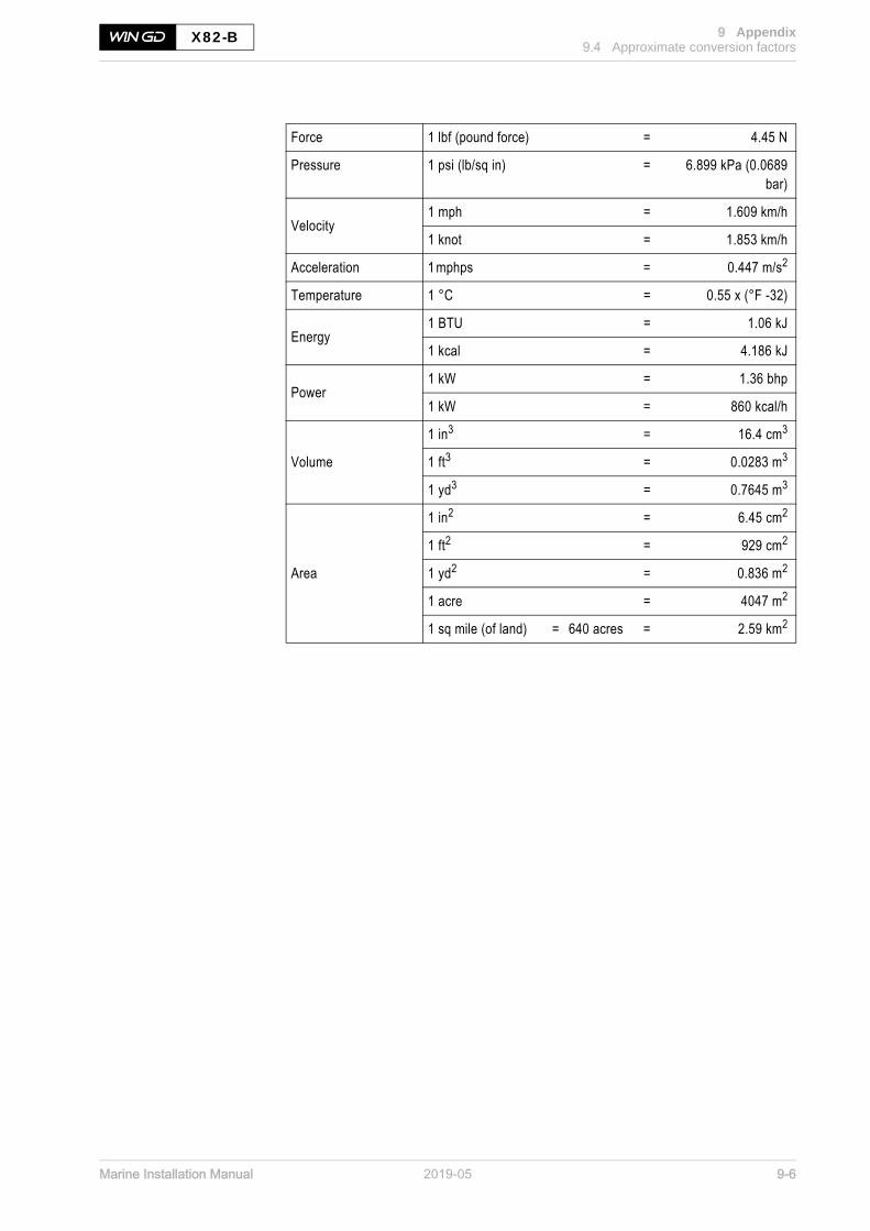
Marine Installation Manual 2019-05 9-6
9 Appendix9.4 Approximate conversion factors
X82-B
Force 1 lbf (pound force) = 4.45 N
Pressure 1 psi (lb/sq in) = 6.899 kPa (0.0689bar)
Velocity1 mph = 1.609 km/h
1 knot = 1.853 km/h
Acceleration 1 mphps = 0.447 m/s2
Temperature 1 °C = 0.55 x (°F -32)
Energy1 BTU = 1.06 kJ
1 kcal = 4.186 kJ
Power1 kW = 1.36 bhp
1 kW = 860 kcal/h
Volume
1 in3 = 16.4 cm3
1 ft3 = 0.0283 m3
1 yd3 = 0.7645 m3
Area
1 in2 = 6.45 cm2
1 ft2 = 929 cm2
1 yd2 = 0.836 m2
1 acre = 4047 m2
1 sq mile (of land) = 640 acres = 2.59 km2

Winterthur Gas & Diesel in brief
Winterthur Gas & Diesel Ltd. (WinGD) is a leading developer of two-stroke low-speed gas and diesel engines usedfor propulsion power in merchant shipping. WinGD’s target is to set the industry standard for reliability, efficiency and environmental friendliness. WinGD provides designs, licences and technical support to manufacturers, shipbuilders and ship operators worldwide. The engines are manufactured under licence in four shipbuilding countries. WinGD has its headquarters in Winterthur, Switzerland, where its activities were founded in 1898.
www.wingd.com
Related Documents