Marine Engine Installation Guide Marine Engine Installation Guide

Welcome message from author
This document is posted to help you gain knowledge. Please leave a comment to let me know what you think about it! Share it to your friends and learn new things together.
Transcript

Marine Engine
Installation Guide
Marine Engine
Installation Guide

2
Safety Precautions!A Keep the engine, gearbox and surrounding area
clean, including the area immediately below the engine.
B Drives - Power Take Off Areas
i) Gearbox Output Flange
The purpose of a marine diesel propulsion engine is to provide motive power to propel a vessel. Accordingly the gearbox output shaft rotates at between 280 and 2400 rev/min. This flange is designed to be coupled to a propeller shaft by the installer and steps must be taken to ensure adequate guarding.
ii) Forward End Drive
Engines are supplied with unguarded belt drives to power the fresh water pump and battery charging alternator. The installer must ensure that it is not possible for injury to occur by allowing access to this area of the engine. The three pulleys run at high speed and can cause injury if personnel or clothing come in contact with the belts or pulleys, when the engine is running.
iii) Power Take Off Shaft (Engine Mounted Option)
Shaft extensions are available as an option and rotate at between 850 and 3600 rev/min. If contact is made with this shaft when the engine is running, injury can occur.
C Exhaust Outlet
Diesel marine propulsion engines emit exhaust gases at very high temperatures - around 400 - 500°C. Engines are supplied with either wet exhaust outlet (water injection bend) or dry outlet (dry exhaust stub) - see option list. At the outlet next to the heat exchanger/header tank, the exhaust outlet can become very hot and if touched, can injure. This must be lagged or avoided by ensuring adequate guarding. It is the responsibility of the installer to lag the exhaust system if a dry system is used. Exhaust gases are harmful if ingested, the installer must therefore ensure that exhaust pipes are led overboard and that leakage in the vessel does not occur.
D Fuel
i) Fuel Lines
Diesel engines are equipped with high pressure fuel injection pumps, if leakages occur, or if pipes fracture, fuel at a high pressure can harm personnel. Skin must be thoroughly cleaned in the event of contact with diesel fuel.
ii) Fuel Supply Connections
Engines are supplied with 8mm compression fittings. The installer must ensure that when connections are made, they are clean and free of leaks.
E Oil
The Beta propulsion unit is supplied with 2 dipsticks, one for the engine and one for the gearbox. Ensure dipsticks are returned and secure after checking, if not oil leaks can cause infection when touched. All oil must be removed from the skin to prevent infection.
F Scalding
An engine running under load will have a closed circuit fresh water temperature of 85° to 95°C. The pressure cap on the top of the heat exchanger must not be removed when the engine is running. It can only be removed when the engine is stopped and has cooled down.
G Transportation / Lifting
Engines are supplied on transportable pallets. Lifting eyes on engines are used for lifting engine and gearbox assembly only, not the pallet and associated kit.
GENERAL DECLARATION
This machinery is not intended to be put into service until it has been incorporated into or with other machinery. It is the responsibility of the purchaser / installer / owner, to ensure that the machinery is properly guarded and that all necessary health and safety requirements, in accordance with the laws of the relevant country, are met before it is put into service.
Signed:
J A Growcoot, C.E.O, Beta Marine Limited.
NOTE: Recreational Craft
Where applicable, the purchaser / installer / owner and operator must be responsible for making sure that the Recreational Craft Directive 94/25/EC is complied with.

3
Section 1
Keel cooled engine, overheating is sometimes caused by:
a) Not fully venting the engine cooling system of air. It is
necessary to remove all air from the cooling system -
including the “skin” tanks and (if fitted) the Calorifier
and associated piping.
b) Incorrectly sized “skin” tanks that have been sized for
‘usual’ canal use, rather than maximum engine output
that can sometimes be required on fast flowing rivers.
An additional “skin” tank may need to be fitted; please
refer to our website: Inland waterways - guidelines:
keel cooling tank sizes.
INSTALLATION RECOMMENDATIONS FOR KEEL COOLED ENGINES{
The installation details are basic guidelines to assist
installation, however due to the great diversity of marine
craft it is impossible to give definitive instructions.
Therefore Beta Marine can accept no responsibility for any
damage or injury incurred during the installation of a Beta
Marine Engine whilst following these guidelines.
• All engines shall be placed within an enclosure
separated from living quarters and installed so as to
minimise the risk of fires or spread of fires as well as
hazards from toxic fumes, heat, noise or vibrations in
the living quarters.
• Unless the engine is protected by a cover or its own
enclosure, exposed moving or hot parts of the engine
that could cause personal injury shall be effectively
shielded.
• Engine parts and accessories that require frequent
inspection and / or servicing must be readily
accessible.
• The insulating materials inside engine spaces shall be
non-combustible.
INSTALLATION RECOMMENDATIONS{
The engine compartment needs air.
a) as air (oxygen) to burn the diesel fuel, and
b) as air to keep the engine cool (still hot at 100°C)
by ventilation.
It is important that the engine compartment has adequate
ventilation, and this is your responsibility. If there is no
ventilation the engine can overheat and damage can be
caused. As a general statement an engine will produce
radiated heat - approximately equal to 1/3 of the engine
output power. Also the larger battery charging alternators
create lots of heat. (A symptom of overheating problems
is often black belt dust). If you have any doubts about
the temperature of your engine compartment please
check with a thermometer on a hot day, the maximum
temperature in the engine compartment should be less
than 70°C - the cooler the better!
Engine compartment ventilation is normally best with two
holes; an inlet allowing colder air to enter below to the
alternator and drive belts and a second outlet (about the
same size) for the hot air to rise and ventilate out from the
top of the engine compartment. Adequate ventilation must
be included with all installations. Installations require a
good quality reliable electric ventilation fan wired into the
ignition switch to remove the hot air. The required air flow
volumes in m3/min = 0.05 x engine power in hp.
VENTILATION{
10hp 20hp 30hp 40hp 50hp 75hp 100hp 150hp
Combustion 14 cm2 28 cm2 43 cm2 57 cm2 71 cm2 106 cm2 142 cm2 213 cm2
Ventilation 13 cm2 25 cm2 37 cm2 50 cm2 62 cm2 92 cm2 123 cm2 185 cm2
Inlet / Outlet dia. 6 cm 9 cm 11 cm 12 cm 13 cm 16 cm 19 cm 22 cm
Typical ventilation sizes

4
Beta Marine propulsion engines can be installed at angles
up to a maximum of 15° flywheel up or flywheel down
when static, and can be run at up to 25° when heeling.
However if you are considering installing above 12° please
contact Beta Marine or alternatively consider the 7° down
angle gearbox. When our engines are installed at varying
angles of inclination the normal markings on the dipstick
should be disregarded. It is probably better to totally drain
the sump, and completely refill the engine sump with the
recommended quantity / volume of lubricating oil - noting
its position on the dipstick - and then marking the dipstick
accordingly (don’t forget to replace the oil filter). If in doubt ask Beta Marine!
ENGINE INSTALLATION AT AN ANGLE{
To ensure vibration free operation, the engine must be
installed and correctly aligned on substantial engine
bearers, extending as far forward and aft as possible, well
braced and securely fastened to form an integral part of
the hull.
The engine must be installed as low as possible on the
flexible mount pillar stud. This will limit vibration and
extend the life of the flexible mount. To assist with engine
replacement we offer ‘Special Engine Feet’ manufactured
to your dimensions, as an optional extra to suit your
existing engine bearers and shaft alignment / installation.
WARNING!• Do not set the engine feet high up the flexible mount
pillar stud. This will cause excessive engine movement
and vibration. Pack steel shims under the flexible
mount and ensure that the flexible mounting is
securely bolted to the engine bearer.
• The pillar stud on the flexible mount is secured into
position by the lower locknut, do not forget to tighten
this. Also ensure that the stud is not screwed too far through the mounting body so that it can touch the bearer. This will cause vibration and knocking noises which are very hard to find! If the flexible mounting is
too far offset then the loading on the flexible mounting
will cause premature failure, modifications are needed.
ENGINE MOUNTING{
RecommendedCorrect height
and positioning
AcceptableShim(s) required to achieve
correct height and positioning
NOT RecommendedPositioning too high on the
pillar stud - requires shims
NOT AcceptableNOT aligned - requires
bearer modifications to correct
4 Engine Mount
5 Engine Mount Alignment
Shim

5
The engine mountings and the couplings must now be tightened in position and the alignment re-checked.
To obtain accurate alignment the flexible mountings must
be adjusted until alignment is attained, and the mountings
must be locked in position. The engine / gearbox unit has
to be aligned with the propeller shaft in two ways. The
traditional engine alignment method involves measuring
with either feeler gauges or a DTI (Dial Test Indicator)
mounted on a magnetic foot so that they are aligned
within 0.125mm (0.005”). (Obviously the propeller shaft
must be centered in the stern tube and running true -
through the cutless bearing; if the propeller shaft is not
correctly centered you will experience vibration).
ALIGNMENT{
Angular Mis-alignmentEngine / gearbox
flangePropeller
shaft
ANGULAR ALIGNMENT
6 Angular Mis-alignment
Parallel Mis-alignmentEngine / gearbox
flangePropeller
shaft
PARALLEL ALIGNMENT
7 Parallel Mis-alignment

6
A flexible coupling is mounted on the gearbox output flange and is strongly recommended in almost every case. Flexible
couplings do not resolve bad alignment, they are designed to absorb torsional vibrations from the propeller (transmitted
along the propeller shaft).
We normally offer two types:
R&D with a flexible nylon disc and optional Clamp Coupling – a very good economical solution.
The excellent ‘CentaFlex’ coupling design includes lots of rubber to absorb torsional shocks and loads. The ‘CentaFlex’ coupling is complete, replacing both the R&D flexible and the R&D clamp couplings above.
FLEXIBLE OUTPUT COUPLINGS{
10 CentaFlex AM Couplings
9 R&D Clamp Couplings - Optional8 R&D Flexible Couplings

7
Owners need to be aware of three major problems that
can easily occur when installing an engine in a sailing
yacht or motor boat and allowing the engine to ‘hydraulic
lock’.
• Seawater syphoning past worn impellors in the
seawater pump, flooding the exhaust system, and
back filling into the combustion chamber when the
engine is stopped.
• Seawater washing into the combustion chamber from
the exhaust system due to either a very shallow
exhaust run from the injection bend to the waterlock
silencer, or because the waterlock silencer is too
small to accept the total amount of cooling water in
the exhaust hoses, or both. This can happen when the
yacht is sailing into a big sea and a surge is set up in
exhaust system as the yacht pitches - with the engine
switched off.
• Waves forcing water up the exhaust due a poorly
designed system with no ‘gooseneck’. Small work
boats moored on exposed beaches are very vulnerable
to this as waves hit the stern before the boat can
swing into the wind on a rising tide.
It is therefore very important to ensure that the engine will
not ‘hydraulic lock’. This can be a problem with engine
installations. When water enters the combustion chamber
and ‘hydraulics’ against the rising piston, a bent con rod,
emulsified engine oil and a wrecked fuel pump can be the
result. It’s best avoided!
If your engine is installed below the water line, the
potential for water entering the engine is considerably
increased. The important dimension that must be
measured is from the normal ‘static’ sea level to the point
at where the cooling water is injected into the exhaust -
this should be a minimum of 25 cms. If this can not be
achieved the following options must be taken (see 11, 12
and 13).
STANDARD YACHT - WET EXHAUST INSTALLATION{
Normal SeaWater Level
25 cm
40 cm
Waterlock Silencer
Rope Cutter
Propeller Clearance
Gooseneck
11 Standard Exhaust System
There are two main types of exhaust system:
1) Standard yacht - wet exhaust system with a water injection bend and waterlock silencer
2) Dry exhaust system (see page 17)
We recommend care when designing your exhaust
system. The most important aspect is to ensure that water
cannot enter the engine’s combustion chamber from the
exhaust system (this applies to both wet and dry exhaust
systems).
EXHAUST SYSTEMS{
8
50 cm
13 Exhaust with Anti-syphon Valve
50 cm
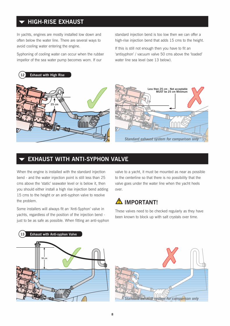
In yachts, engines are mostly installed low down and
often below the water line. There are several ways to
avoid cooling water entering the engine.
Syphoning of cooling water can occur when the rubber
impellor of the sea water pump becomes worn. If our
standard injection bend is too low then we can offer a
high-rise injection bend that adds 15 cms to the height.
If this is still not enough then you have to fit an
‘antisyphon’ / vacuum valve 50 cms above the ‘loaded’
water line sea level (see 13 below).
HIGH-RISE EXHAUST{
When the engine is installed with the standard injection
bend - and the water injection point is still less than 25
cms above the ‘static’ seawater level or is below it, then
you should either install a high rise injection bend adding
15 cms to the height or an anti-syphon valve to resolve
the problem.
Some installers will always fit an ‘Anti-Syphon’ valve in
yachts, regardless of the position of the injection bend -
just to be as safe as possible. When fitting an anti-syphon
valve to a yacht, it must be mounted as near as possible
to the centerline so that there is no possibility that the
valve goes under the water line when the yacht heels
over.
IMPORTANT!These valves need to be checked regularly as they have
been known to block up with salt crystals over time.
EXHAUST WITH ANTI-SYPHON VALVE{
25 cm
Less then 25 cm - Not acceptableMUST be 25 cm Minimum
12 Exhaust with High Rise
25 cm
Less then 25 cm - Not acceptableMUST be 25 cm Minimum
Standard exhaust system for comparison only
Standard exhaust system for comparison only
9
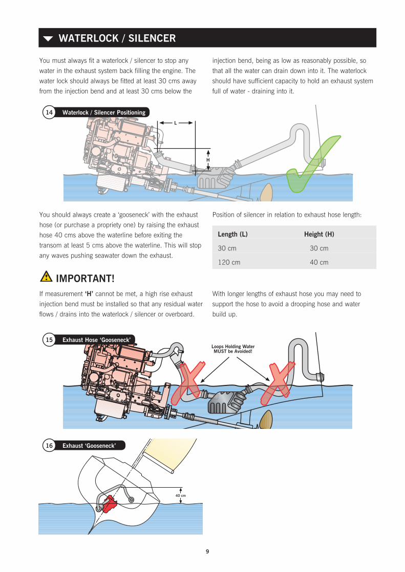
You should always create a ‘gooseneck’ with the exhaust
hose (or purchase a propriety one) by raising the exhaust
hose 40 cms above the waterline before exiting the
transom at least 5 cms above the waterline. This will stop
any waves pushing seawater down the exhaust.
IMPORTANT!If measurement ‘H’ cannot be met, a high rise exhaust
injection bend must be installed so that any residual water
flows / drains into the waterlock / silencer or overboard.
Position of silencer in relation to exhaust hose length:
With longer lengths of exhaust hose you may need to
support the hose to avoid a drooping hose and water
build up.
Length (L) Height (H)
30 cm 30 cm
120 cm 40 cm
WATERLOCK / SILENCER{
Loops Holding WaterMUST be Avoided!
15 Exhaust Hose ‘Gooseneck’
H
L
14 Waterlock / Silencer Positioning
40 cm
16 Exhaust ‘Gooseneck’
You must always fit a waterlock / silencer to stop any
water in the exhaust system back filling the engine. The
water lock should always be fitted at least 30 cms away
from the injection bend and at least 30 cms below the
injection bend, being as low as reasonably possible, so
that all the water can drain down into it. The waterlock
should have sufficient capacity to hold an exhaust system
full of water - draining into it.

10
4. A normal inlet sea cock type ‘A’ (as shown in 17
above) is recommended as this can be ‘rodded out’
to remove blockages. We do not recommend the use
of ‘Scoop’ type water pickups, because if fitted the
wrong way around the water will be forced through the
pump and into the exhaust system whilst the vessel
is sailing. This is very dangerous as the exhaust will
eventually fill and sea / raw water will back up into the
engine through the exhaust valve. Catastrophic failure
will result as soon as the engine is restarted.
18 Sea Water Inlet - Scoop
Sea Water Level
Sea Water Level
17 Sea Water Inlet / Filter
‘A’
‘B’
Your engine is fitted with a gear driven sea water pump
which sucks in seawater (raw water) to cool the closed
circuit system via the heat exchanger.
1. It is very important that the seawater inlet should have
a strainer system either ‘A’ built into the sea cock, or
‘B’ a high level system with visual inspection glass (as
shown) mounted just above the water line.
2. Good access to the inlet sea cock from inside your
boat is essential so that plastic bags or seaweed
trapped in the intake can be poked out.
3. All pipe work should have approved marine grade
stainless steel hose clips. Any loose clamps or bad
connections can cause flooding and sinking of the
vessel. It is accepted practice that two stainless steel
clips should be used at each end of raw water pipes
for security. Ensure that you use the correct grade of
hose.
Note: The maximum lift of the sea water pump is 2m
when primed.
SEA WATER INLET FOR HEAT EXCHANGER COOLED ENGINES{
Seacock Inlet / Seawater Engine Pump Hose I.D.
Beta 10 to Beta 38 19 mm (3/4“) min.
Beta 43 to Beta 60 25 mm (1“) min.
Beta 75 to Beta 105 28 mm (11/4”) min.

11
If your installation requires a water ‘bleed’ for stern gear
lubrication of the cutlass bearing it can be taken from the
engine as it leaves the heat exchanger.
19 Stern Bleed Feed
STERN GEAR LUBRICATION{
Beta 10 to Beta 60 - can be connected to the heat
exchanger end cap using our ‘Stern Bleed kit’ and drilling
and tapping the end cap.
Beta 75 upwards - need a ‘T’ piece with an 1/8” BSP
connection fitted just after the heat exchanger as shown
in the drawing. It is important that this ‘feed’ is taken
from the engine side of an anti-syphon valve or you can
‘hydraulic’ the engine with catastrophic results.
20 Standard Exhaust with Stern Bleed 21 Stern Bleed with Anti-syphon Valve

12
EXHAUST BACK PRESSURE{
Keep exhaust systems to a minimum length and have
gradual bends (NOT right angle elbows). Exhaust back
pressure should be as low as possible; it is increased
by long exhaust length and sharp bends. Back pressure
should be measured with the complete exhaust system
connected and the engine running at full speed. The
correct measuring point is before the injection bend (at
the manifold flange). We can supply a Manometer kit for
testing ‘Back Pressure’.
Engine Exhaust Back Pressure
Beta 10 to Beta 25 Max. 70 mm Hg
Beta 30 to Beta 60 Max. 80 mm Hg
Beta 75 & Beta 90 Max. 90 mm Hg
Beta 105 85 to 115 mmHg
EXHAUST HOSE{
Wet exhaust hose should be matched to the injection
bend diameter. An engine correctly installed in
accordance with this handbook will meet the emission
requirements of the RCD (Recreational Craft Directive).
Engine Exhaust Hose I.D.
Beta 10 to Beta 60 50 mm
Beta 75 & Beta 90 60 mm
Beta 105 75 mm
There must be a propeller clearance between the tip of
the propeller blade and the underside of the hull.
This should be a minimum of 10% of the diameter of the
propeller (some say 15%) to reduce ‘tip noise’.
PROPELLER CLEARANCE{
10% of Prop Dia.
x x
22 Propeller Clearance

13
FlexibleExhaust Hose
Silencer
Silencer
24 Dry Exhaust System
FlexibleExhaust Hose
Silencer
Silencer
a) An engine correctly installed in accordance with this
handbook will meet the emission requirements of the
RCD (see back of manual).
b) Keep exhaust systems to a minimum length and
have gradual bends, refer to ‘exhaust back pressure’
bottom of page 16 for futher information .
c) The dry exhaust system installed in a canal boat
or work boat should be 11/2” minimum internal
diameter.
The engine is fitted with a 11/2” BSP male connector
stub as standard - Valid for exhaust systems up to
3 metres in length. A flexible exhaust bellows and
dry exhaust silencer should be used. It is up to
the installer to work out his own pipe run but care
should be taken as follows:
• Never use a flexible exhaust bellow as a bend, it will
crack, always keep them straight.
• Ensure that rain water (or any other water - say from
the side of the loch) cannot enter the exhaust port
and run back down the system, flooding the silencer
and eventually the engine (see drawings below).
• The system should be lagged if there is any danger of
the crew getting near it.
• A dry exhaust system will give off considerable heat
and suitable insulation and ventilation must be
provided.
DRY EXHAUST INSTALLATION{
23 Dry Exhaust System
Ensure exhaust raises then falls to outlet
14
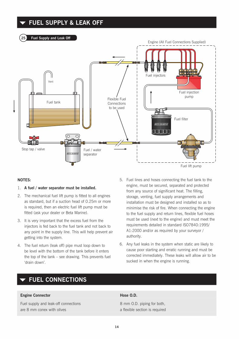
FUEL SUPPLY & LEAK OFF{
NOTES:
1. A fuel / water separator must be installed.
2. The mechanical fuel lift pump is fitted to all engines as standard, but if a suction head of 0.25m or more is required, then an electric fuel lift pump must be fitted (ask your dealer or Beta Marine).
3. It is very important that the excess fuel from the injectors is fed back to the fuel tank and not back to any point in the supply line. This will help prevent air getting into the system.
4. The fuel return (leak off) pipe must loop down to be level with the bottom of the tank before it enters the top of the tank – see drawing. This prevents fuel ‘drain down’.
5. Fuel lines and hoses connecting the fuel tank to the engine, must be secured, separated and protected from any source of significant heat. The filling, storage, venting, fuel supply arrangements and installation must be designed and installed so as to minimise the risk of fire. When connecting the engine to the fuel supply and return lines, flexible fuel hoses must be used (next to the engine) and must meet the requirements detailed in standard ISO7840:1995/A1:2000 and/or as required by your surveyor / authority.
6. Any fuel leaks in the system when static are likely to cause poor starting and erratic running and must be corrected immediately. These leaks will allow air to be sucked in when the engine is running.
Fuel tank
Stop tap / valve Fuel / water separator
Fuel filter
Fuel lift pump
Fuel injection pump
Engine (All Fuel Connections Supplied)
Flexible Fuel Connections to be used
Fuel injectors
Vent
25 Fuel Supply and Leak Off
FUEL CONNECTIONS{
Engine Connector Hose O.D.
Fuel supply and leak-off connections 8 mm O.D. piping for both,
are 8 mm conex with olives a flexible section is required

15
CALORIFIER SYSTEM{
a
a
26 Heat Exchanger Calorifier System
a
a
27 Keel Cooled Calorifier System
All Beta engines can be fitted with the calorifier
connections to allow the coolant from the closed circuit
cooling system to circulate through a calorifier tank,
which in turn heats up domestic water. Calorifier
connections on this range of engine are shown.
1. The big problem with a calorifier is to remove all the
air from the system. If this is not achieved then they
don’t work!
2. Try and keep the supply and return pipes either
horizontal or sloping down in a continuous fall
towards the calorifier. This avoids air pockets being
created.
3. Extra care must be taken when first connecting the
calorifier circuit system to the engine as the coolant
level in the heat exchanger may appear to be full but
it soon disappears into the calorifier pipe work. Run
the engine off load for 10 minutes then check the
level as described in ‘Filling The Fresh Water System’.
Also check to see if the pipe going to the calorifier is
getting warm. Top up the water level as required and
run for another ten minutes then repeat.
4. If the water level is steady but no warm water is
getting to the Calorifier then (with engine stopped)
very carefully remove the pressure/filler cap using
a large rag/cloth to protect you hand from scalding.
Now very carefully open the Calorifier bleed valve
(see manufacturers instructions) or if none is provided
then very carefully loosen the jubilee clip securing
the supply pipe to the Calorifier. Air should escape.
Refasten securely when no further bubbles are seen.
5. If the calorifier tank is fitted above the heat exchanger /
header tank then you will need to fit a remote header
tank slightly above the calorifier tank.
CAUTION: TO AVOID PERSONAL INJURY!
Do not do this when the engine is hot as scalding hot
water may be forced out of the pipe under pressure.
28
29
Calorifier connection
Calorifier connection

16
Most narrowboats on English canals have keel cooling,
and this is standard for our ‘Green Line’ Narrowboats’
and ‘Wide Beamers’ (heat exchanger cooling is available
as an option if required).
The Beta 75 and Beta 90 propulsion engines arranged
for keel cooling have both engine supply and return
copper pipes of 32mm diameter; requiring flexible
rubber hoses with a 32mm bore. These rubber hoses
should be designed and manufactured as hot water
heater hoses suitable for operation up to 100°C.
Narrowboats: With keel cooling the coolant (same fresh
water / antifreeze solution as heat exchanger cooling)
flows around the engine and also the keel cooling tanks,
before returning to the engine.
These keel cooling tanks are normally welded into the
‘swim’ of the narrowboat, using the 8mm steel plate hull
as one side of the tank to transfer the engine heat to the
canal water. The required surface area for keel cooling
our engines in narrowboats is as detailed.
CANAL BOATS WITH KEEL COOLERS{
Bleed Screw
Baffle
HotWater In
ColdWater Out
Baffle GapMin. ø D x1.5Max. ø D x 3.0
ø D
H
B
A
30 Ideal Keel Cooling Tank
NOTE: If you boat has a hydraulic drive, you will need to increase the surface area by approximately 30% percent.
Keel cooling pipes under the hull of yachts or work boats, that achieve the same surface area can also be used. If you
have any questions about keel cooling please refer to our design guidelines detailed on our website, or ask us.
The keel cooling tank size should have a
surface area exposed to the canal or sea water of:
0.25 x the bhp of the engine = the square feet
of cooling area required (for steel hulls)
A X B = SURFACE AREA(MUST BE BELOW WATER LEVEL)
17
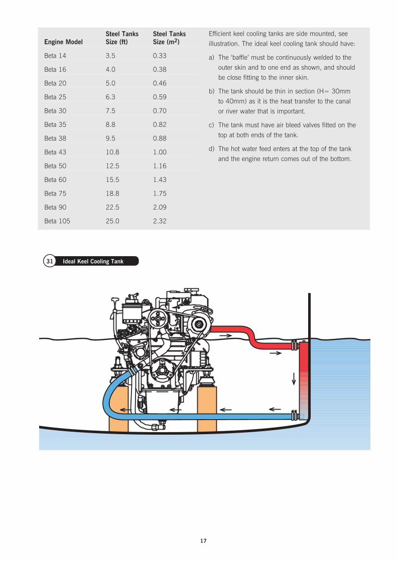
31 Ideal Keel Cooling Tank
Steel Tanks Steel Tanks Engine Model Size (ft) Size (m2)
Beta 14 3.5 0.33
Beta 16 4.0 0.38
Beta 20 5.0 0.46
Beta 25 6.3 0.59
Beta 30 7.5 0.70
Beta 35 8.8 0.82
Beta 38 9.5 0.88
Beta 43 10.8 1.00
Beta 50 12.5 1.16
Beta 60 15.5 1.43
Beta 75 18.8 1.75
Beta 90 22.5 2.09
Beta 105 25.0 2.32
Efficient keel cooling tanks are side mounted, see
illustration. The ideal keel cooling tank should have:
a) The ‘baffle’ must be continuously welded to the
outer skin and to one end as shown, and should
be close fitting to the inner skin.
b) The tank should be thin in section (H= 30mm
to 40mm) as it is the heat transfer to the canal
or river water that is important.
c) The tank must have air bleed valves fitted on the
top at both ends of the tank.
d) The hot water feed enters at the top of the tank
and the engine return comes out of the bottom.
18
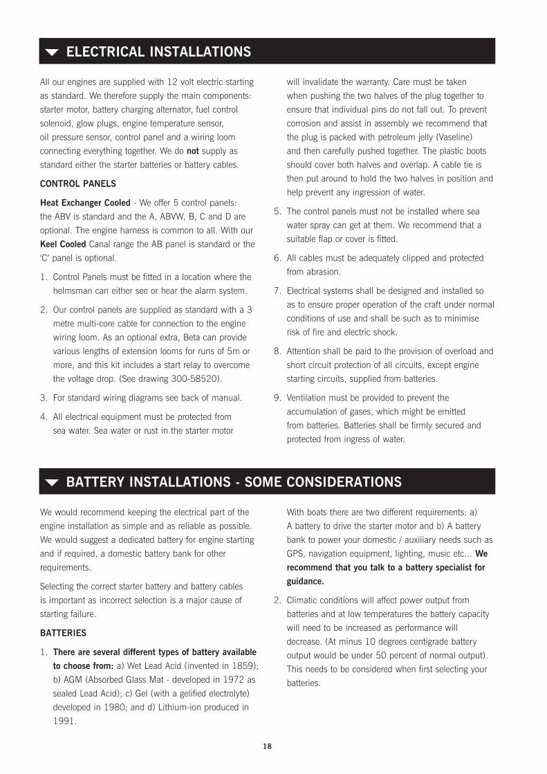
All our engines are supplied with 12 volt electric starting
as standard. We therefore supply the main components:
starter motor, battery charging alternator, fuel control
solenoid, glow plugs, engine temperature sensor,
oil pressure sensor, control panel and a wiring loom
connecting everything together. We do not supply as
standard either the starter batteries or battery cables.
CONTROL PANELS
Heat Exchanger Cooled - We offer 5 control panels:
the ABV is standard and the A, ABVW, B, C and D are
optional. The engine harness is common to all. With our
Keel Cooled Canal range the AB panel is standard or the
‘C’ panel is optional.
1. Control Panels must be fitted in a location where the
helmsman can either see or hear the alarm system.
2. Our control panels are supplied as standard with a 3
metre multi-core cable for connection to the engine
wiring loom. As an optional extra, Beta can provide
various lengths of extension looms for runs of 5m or
more, and this kit includes a start relay to overcome
the voltage drop. (See drawing 300-58520).
3. For standard wiring diagrams see back of manual.
4. All electrical equipment must be protected from
sea water. Sea water or rust in the starter motor
will invalidate the warranty. Care must be taken
when pushing the two halves of the plug together to
ensure that individual pins do not fall out. To prevent
corrosion and assist in assembly we recommend that
the plug is packed with petroleum jelly (Vaseline)
and then carefully pushed together. The plastic boots
should cover both halves and overlap. A cable tie is
then put around to hold the two halves in position and
help prevent any ingression of water.
5. The control panels must not be installed where sea
water spray can get at them. We recommend that a
suitable flap or cover is fitted.
6. All cables must be adequately clipped and protected
from abrasion.
7. Electrical systems shall be designed and installed so
as to ensure proper operation of the craft under normal
conditions of use and shall be such as to minimise
risk of fire and electric shock.
8. Attention shall be paid to the provision of overload and
short circuit protection of all circuits, except engine
starting circuits, supplied from batteries.
9. Ventilation must be provided to prevent the
accumulation of gases, which might be emitted
from batteries. Batteries shall be firmly secured and
protected from ingress of water.
ELECTRICAL INSTALLATIONS{
We would recommend keeping the electrical part of the
engine installation as simple and as reliable as possible.
We would suggest a dedicated battery for engine starting
and if required, a domestic battery bank for other
requirements.
Selecting the correct starter battery and battery cables
is important as incorrect selection is a major cause of
starting failure.
BATTERIES
1. There are several different types of battery available to choose from: a) Wet Lead Acid (invented in 1859);
b) AGM (Absorbed Glass Mat - developed in 1972 as
sealed Lead Acid); c) Gel (with a gelified electrolyte)
developed in 1980; and d) Lithium-ion produced in
1991.
With boats there are two different requirements: a)
A battery to drive the starter motor and b) A battery
bank to power your domestic / auxiliary needs such as
GPS, navigation equipment, lighting, music etc... We recommend that you talk to a battery specialist for guidance.
2. Climatic conditions will affect power output from
batteries and at low temperatures the battery capacity
will need to be increased as performance will
decrease. (At minus 10 degrees centigrade battery
output would be under 50 percent of normal output).
This needs to be considered when first selecting your
batteries.
BATTERY INSTALLATIONS - SOME CONSIDERATIONS{
19
3. All our engines are supplied with one battery charging
alternator, sometimes two. Our electric starting circuit
is nominal 12 volts and we fit as standard a 40 amp
battery charging alternator up to Beta 25, and a 70
amp alternator from the Beta 30.
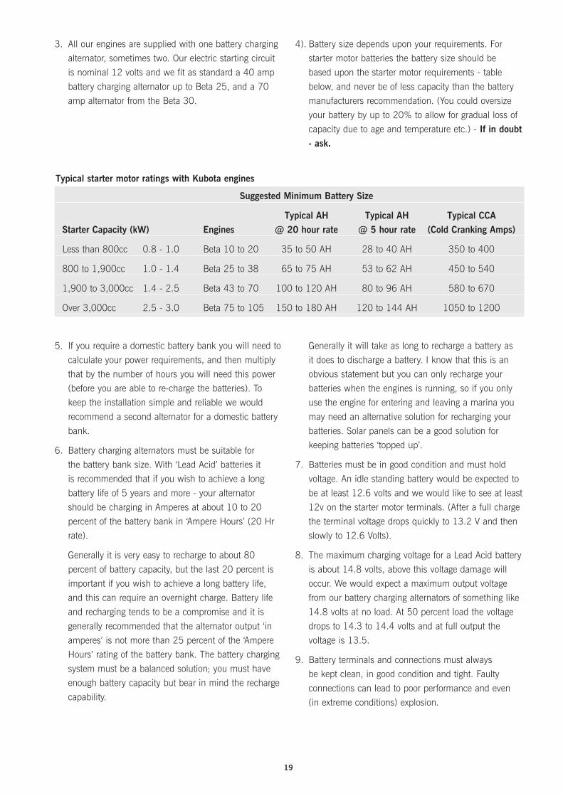
4). Battery size depends upon your requirements. For
starter motor batteries the battery size should be
based upon the starter motor requirements - table
below, and never be of less capacity than the battery
manufacturers recommendation. (You could oversize
your battery by up to 20% to allow for gradual loss of
capacity due to age and temperature etc.) - If in doubt - ask.
5. If you require a domestic battery bank you will need to
calculate your power requirements, and then multiply
that by the number of hours you will need this power
(before you are able to re-charge the batteries). To
keep the installation simple and reliable we would
recommend a second alternator for a domestic battery
bank.
6. Battery charging alternators must be suitable for
the battery bank size. With ‘Lead Acid’ batteries it
is recommended that if you wish to achieve a long
battery life of 5 years and more - your alternator
should be charging in Amperes at about 10 to 20
percent of the battery bank in ‘Ampere Hours’ (20 Hr
rate).
Generally it is very easy to recharge to about 80
percent of battery capacity, but the last 20 percent is
important if you wish to achieve a long battery life,
and this can require an overnight charge. Battery life
and recharging tends to be a compromise and it is
generally recommended that the alternator output ‘in
amperes’ is not more than 25 percent of the ‘Ampere
Hours’ rating of the battery bank. The battery charging
system must be a balanced solution; you must have
enough battery capacity but bear in mind the recharge
capability.
Generally it will take as long to recharge a battery as
it does to discharge a battery. I know that this is an
obvious statement but you can only recharge your
batteries when the engines is running, so if you only
use the engine for entering and leaving a marina you
may need an alternative solution for recharging your
batteries. Solar panels can be a good solution for
keeping batteries ‘topped up’.
7. Batteries must be in good condition and must hold
voltage. An idle standing battery would be expected to
be at least 12.6 volts and we would like to see at least
12v on the starter motor terminals. (After a full charge
the terminal voltage drops quickly to 13.2 V and then
slowly to 12.6 Volts).
8. The maximum charging voltage for a Lead Acid battery
is about 14.8 volts, above this voltage damage will
occur. We would expect a maximum output voltage
from our battery charging alternators of something like
14.8 volts at no load. At 50 percent load the voltage
drops to 14.3 to 14.4 volts and at full output the
voltage is 13.5.
9. Battery terminals and connections must always
be kept clean, in good condition and tight. Faulty
connections can lead to poor performance and even
(in extreme conditions) explosion.
Typical starter motor ratings with Kubota engines
Suggested Minimum Battery Size
Typical AH Typical AH Typical CCA Starter Capacity (kW) Engines @ 20 hour rate @ 5 hour rate (Cold Cranking Amps)
Less than 800cc 0.8 - 1.0 Beta 10 to 20 35 to 50 AH 28 to 40 AH 350 to 400
800 to 1,900cc 1.0 - 1.4 Beta 25 to 38 65 to 75 AH 53 to 62 AH 450 to 540
1,900 to 3,000cc 1.4 - 2.5 Beta 43 to 70 100 to 120 AH 80 to 96 AH 580 to 670
Over 3,000cc 2.5 - 3.0 Beta 75 to 105 150 to 180 AH 120 to 144 AH 1050 to 1200
20
1. Starter batteries should be as close to the engine as
practically possible. The reason for this is to ensure
that the maximum voltage from the battery is available
to the starter motor. The longer the cable run - the
more will be the voltage drop. This is due to the
resistance of the cables.
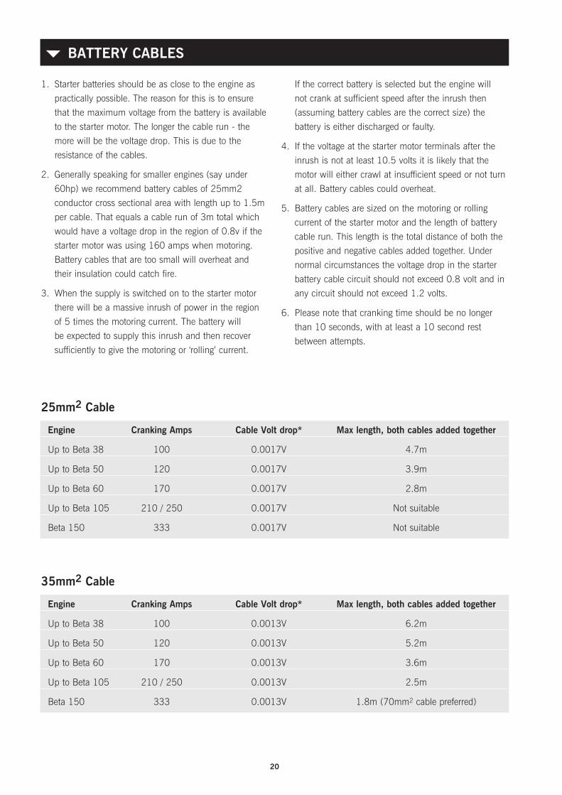
2. Generally speaking for smaller engines (say under
60hp) we recommend battery cables of 25mm2
conductor cross sectional area with length up to 1.5m
per cable. That equals a cable run of 3m total which
would have a voltage drop in the region of 0.8v if the
starter motor was using 160 amps when motoring.
Battery cables that are too small will overheat and
their insulation could catch fire.
3. When the supply is switched on to the starter motor
there will be a massive inrush of power in the region
of 5 times the motoring current. The battery will
be expected to supply this inrush and then recover
sufficiently to give the motoring or ‘rolling’ current.
If the correct battery is selected but the engine will
not crank at sufficient speed after the inrush then
(assuming battery cables are the correct size) the
battery is either discharged or faulty.
4. If the voltage at the starter motor terminals after the
inrush is not at least 10.5 volts it is likely that the
motor will either crawl at insufficient speed or not turn
at all. Battery cables could overheat.
5. Battery cables are sized on the motoring or rolling
current of the starter motor and the length of battery
cable run. This length is the total distance of both the
positive and negative cables added together. Under
normal circumstances the voltage drop in the starter
battery cable circuit should not exceed 0.8 volt and in
any circuit should not exceed 1.2 volts.
6. Please note that cranking time should be no longer
than 10 seconds, with at least a 10 second rest
between attempts.
BATTERY CABLES{
25mm2 Cable
Engine Cranking Amps Cable Volt drop* Max length, both cables added together
Up to Beta 38 100 0.0017V 4.7m
Up to Beta 50 120 0.0017V 3.9m
Up to Beta 60 170 0.0017V 2.8m
Up to Beta 105 210 / 250 0.0017V Not suitable
Beta 150 333 0.0017V Not suitable
35mm2 Cable
Engine Cranking Amps Cable Volt drop* Max length, both cables added together
Up to Beta 38 100 0.0013V 6.2m
Up to Beta 50 120 0.0013V 5.2m
Up to Beta 60 170 0.0013V 3.6m
Up to Beta 105 210 / 250 0.0013V 2.5m
Beta 150 333 0.0013V 1.8m (70mm2 cable preferred)

21
*Voltage drops for pvc insulated cables are ex table 9D1
of the IEE Wiring Regulations.
The above are based on a maximum conductor
temperature of 70°C in an ambient temperature of 30°C.
Please note that it is not practical to use table 9D1 of the
IEE Wiring Regulations for larger sizes. We are after all
talking about short duration power flow not continuous
ratings for the starter motor.
KEYSWITCH TERMINATIONS{
The standard panel keyswitch can be used to tap off a
switched positive ignition feed to power additional gauges.
In this way these gauges will only be live whilst the
engine is running, the engine is starting or the heaters are
being used.
For silver keyswitches, the terminal to achieve this ignition
switched positive is marked ‘AC’.
For panels without any keyswitch, gauges can be
driven from the 1 mm2 brown wire which terminates
at 11 way connector terminal 4. This is a lower power
switched positive, any additional power required from this
connection must be feed through a relay, as noted below.
Note: these keyswitch terminals are rated at 10 amps
maximum, since they are already utilised for panel and
alternator feeds Beta Marine recommend any additional
requirements from these terminals must be fed through
a relay. This relay should then be connected to it’s own
fused positive supply directly from the engine battery.
Beta drawing 202-06421 illustrating the wiring of a
typical electric fuel lift pump with ignition switched relay
can be supplied upon request.
70mm2 Cable
Engine Cranking Amps Cable Volt drop* Max length, both cables added together
Up to Beta 38 100 0.00063V 12.7m
Up to Beta 50 120 0.00063V 10.5m
Up to Beta 60 170 0.00063V 7.5m
Up to Beta 105 210 / 250 0.00063V 5.0m
Beta 150 333 0.00063V 3.8m
At the end of the day what matters is the voltage at the starter motor terminals before starting and whilst cranking, all without destroying the insulation on the cables.
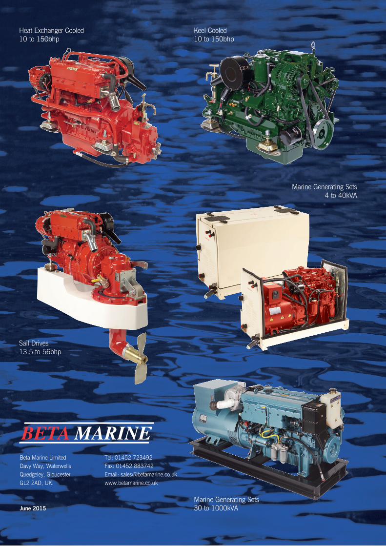
Beta Marine LimitedDavy Way, Waterwells Quedgeley, Gloucester GL2 2AD, UK.
Tel: 01452 723492 Fax: 01452 883742Email: [email protected]
June 2015
Keel Cooled10 to 150bhp
Marine Generating Sets 4 to 40kVA
Heat Exchanger Cooled10 to 150bhp
Sail Drives 13.5 to 56bhp
Marine Generating Sets 30 to 1000kVA
Related Documents