Welcome message from author
This document is posted to help you gain knowledge. Please leave a comment to let me know what you think about it! Share it to your friends and learn new things together.
Transcript

2 www.marinefendersintl .com Copyright 2010
MARINE FENDERS INTERNATIONAL, INC.
Marine Fenders International, Inc. is on the cutting edge of marine fendering and buoyancy system technologies.. As a driving force in themarine industry, Marine Fenders International’s advancements in polyurethane elastomers, a critical components in any composite buoy orfender system, are unparalleled in strength and durability. MFI’s staff has over 30 years of experience in the marine and polyurethaneindustries, which challenges the competition to keep up with our ever increasing standards of excellence through relentless research andtechnological innovation and application.
Byproducts of MFI’s experience are the efficient manufacturingprocesses and facility. These have been designed to provide thehighest quality yet lowest cost products in the world. Additionally, ourmechanical and chemical engineering staff’s Research andDevelopment programs constantly reevaluate these processesthrough constant and critical analysis. New products and designs arecontinuously being developed to meet today’s changing marineindustrial needs.
Marine Fenders International, Inc. is a member of the AmericanStandard and Testing Methods (ASTM) Fendering Task Group whichis responsible for authoring the next generation of marine fenderingspecification. The ASTM organization has recognized the value ofMFI’s experience and highly regard its opinion as these standardsare being established.
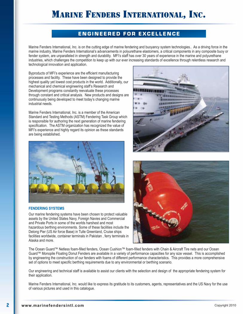
FENDERING SYSTEMS
Our marine fendering systems have been chosen to protect valuableassets by the United States Navy, Foreign Navies and Commercialand Private Ports in some of the worlds harshest and mosthazardous berthing environments. Some of these facilities include theDelong Pier (US Air force Base) in Tulle Greenland, Cruise shipsfacilities worldwide, container terminals in Pakistan , ferry terminals inAlaska and more.
The Ocean Guard™ Netless foam-filled fenders, Ocean Cushion™ foam-filled fenders with Chain & Aircraft Tire nets and our OceanGuard™ Monopile Floating Donut Fenders are available in a variety of performance capacities for any size vessel. This is accomplishedby engineering the construction of our fenders with foams of different performance characteristics. This provides a more comprehensiveset of options to meet specific berthing requirements due to any environmental or berthing scenario.
Our engineering and technical staff is available to assist our clients with the selection and design of the appropriate fendering system fortheir application.
Marine Fenders International, Inc. would like to express its gratitude to its customers, agents, representatives and the US Navy for the useof various pictures and used in this catalogue.
E N G I N E E R E D F O R E XC E L L E N C E

3www.marinefendersintl .com Copyright 2010
T A B L E O F C O N T E N T S
OCEAN GUARD™Netless Foam FilledFender
OCEAN CUSHION™Foam Filled Fenderwith Chain & AircraftTire Nets
OCEAN GUARD™Small Standard Duty
Foam Filled Fender
OCEAN GUARD™Monopile FloatingDonut Fender
OCEAN GUARD™Resilient Foam FilledBuoys
OCEAN GUARD™Resilient DredgeFloats
OCEAN GUARD™Port Security
Barriers Systems
OCEAN GUARD™Coated Piles
OCEAN CAMEL™Composite Camels
MARINEHARDWARE
4 www.marinefendersintl .com Copyright 2010
PERFORMANCE FEATURES
HIGH ENERGY ABSORPTION
Ocean Guard™ Netless Foam Filled Marine Fenders efficientlyabsorb significant amounts of energy with a low correspondingreaction force. By keeping these forces to a minimum significantstructural costs can be reduced when designing a new or upgradeto a berthing facility.
In comparison to equally sized pneumatic fenders Ocean Guard™Netless Foam-Filled Marine Fenders absorb up to 40% moreenergy.
The energy dissipation of the foam core construction allows for agentler recovery after compression. This virtually eliminates therebound effect vessels experience from other types of fenderingsystems such as hard rubber fenders, pile fenders, pneumaticfenders and panel fendering systems.
LOW REACTION FORCE
The advantages of utilizing foam-filled Ocean Guard™ NetlessFenders, with its relatively low reaction force for a given energyabsorption level, should not be overlooked.
The engineered design and construction of Ocean Guard™Netless Fenders produces a fendering system which absorbs agreater amount of energy while experiencing a lower reaction forcethan pneumatic or rubber buckling fender.
Since the reaction force of a fendering system is the force exertedon a berthing structure and the berthing vessel’s hull, pneumaticand buckling type fenders exert greater forces, or pressures, uponthese structures. The negative effect of this dynamic could resultin higher new construction design costs along with highermaintenance costs, over time, on new and existing structures.
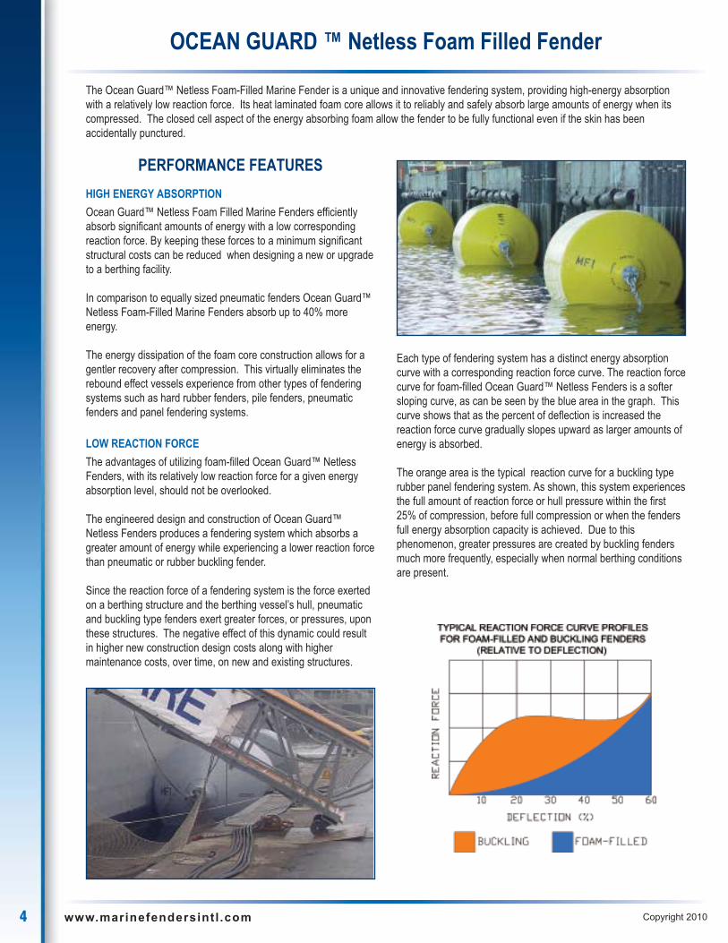
Each type of fendering system has a distinct energy absorptioncurve with a corresponding reaction force curve. The reaction forcecurve for foam-filled Ocean Guard™ Netless Fenders is a softersloping curve, as can be seen by the blue area in the graph. Thiscurve shows that as the percent of deflection is increased thereaction force curve gradually slopes upward as larger amounts ofenergy is absorbed.
The orange area is the typical reaction curve for a buckling typerubber panel fendering system. As shown, this system experiencesthe full amount of reaction force or hull pressure within the first25% of compression, before full compression or when the fendersfull energy absorption capacity is achieved. Due to thisphenomenon, greater pressures are created by buckling fendersmuch more frequently, especially when normal berthing conditionsare present.
The Ocean Guard™ Netless Foam-Filled Marine Fender is a unique and innovative fendering system, providing high-energy absorptionwith a relatively low reaction force. Its heat laminated foam core allows it to reliably and safely absorb large amounts of energy when itscompressed. The closed cell aspect of the energy absorbing foam allow the fender to be fully functional even if the skin has beenaccidentally punctured.
OCEAN GUARD ™ Netless Foam Filled Fender

5www.marinefendersintl .com Copyright 2010
HULL CONFORMING CAPABILITIES
The resilient nature of a foam-filled Ocean Guard™ NetlessFender give it the unique ability to conform to a vessel’s hullcontours and extremities, such as rub rails.
This hull conforming feature eliminates point loading, which occurswith panel type fenders, on hull contours and therefore evenlydistributes energies over a greater surface area. This results inmuch lower hull pressures.
UNSINKABLE AND SAFE
Because of the closed-cell foam core construction in the foam-filledOcean Guard™ Netless Fender design, it is unsinkable and will notexplode. Even if the skin is damaged, the fender will continue tofloat while maintaining its energy absorption and standoffcharacteristics before repairs can be made or the fender bereplaced.
NON MARKING SKIN
The nylon filament reinforced urethane elastomer skin is a non-marking material regardless of the color. This makes the non-marking properties of the foam-filled Ocean Guard™ NetlessFender ideal for light colored vessels, such as cruise ships andother highly visible vessels. Standard skin colors include black,gray, red, safety orange, white and yellow. Custom colorsavailable upon request.
6 www.marinefendersintl .com Copyright 2010
LOW MAINTENANCE
The design of the foam-filled Ocean Guard™ Netless Fender ishighly resistant to environmental hazards such as extremetemperatures, hydrocarbons, fresh and salt water, ozone andultraviolet radiation. The fender skin is even resistant to chemicalssuch as diesel fuels.
Additionally, since the internal construction consists of a solid heatlaminated foam core, there is no need to maintain air pressure,inflation or relief valves, as with pneumatic fenders
Hanging 4-point mounting arrangement Floating 2-point mounting arrangement
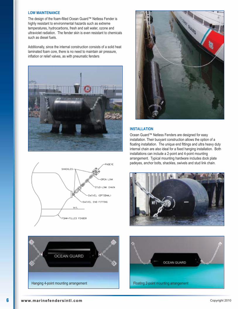
INSTALLATION
Ocean Guard™ Netless Fenders are designed for easyinstallation. Their buoyant construction allows the option of afloating installation. The unique end fittings and ultra heavy dutyinternal chain are also ideal for a fixed hanging installation. Bothinstallations can include a 2-point and 4-point mountingarrangement. Typical mounting hardware includes dock platepadeyes, anchor bolts, shackles, swivels and stud link chain.
7www.marinefendersintl .com Copyright 2010
CONSTRUCTION FEATURES
FOAM CORE
Construction begins with a resilient energy absorbing closed cellcross-linked polyethylene foam core which is heat laminated into aone piece solid foam core. This heat lamination process producesa thermal bond between the layers of foam which is stronger thanthe foam itself which, will not delaminate even under the mostabusive berthing conditions. This ensures that the foam coreconstruction of the fender will provide years of quality service andperformance.
Because of this foam core, if punctured the fender will notexperience a catastrophic failure as would pneumatic fenders.
REINFORCED ELASTOMERIC SKIN
The energy absorbing foam core is protected by a tough thickfilament nylon tire cord reinforced elastomer skin. This non-marking reinforced elastomer fender skin is the wear surface of thefender. The reinforcing filaments are continuously wound in a helixpattern through up to 90 % of the elastomer skin and wrap aroundthe fender swivel end fitting housings on each end of the fender.This continuous reinforcement of the elastomer skin not onlyincreases the tensile and tear strength of the elastomer but alsodistributes loads through out the fender skin.
Our elastomer skin is exemplifies the latest in urethane technology.This tough resilient material is specially formulated to withstand theworlds harshest environmental conditions providing superiorperformance in extreme temperatures, toxic environments, againsthydrocarbons, salt water, ozone, and ultraviolet radiation. Itssmooth sleek construction is not prone to snagging on dock or hullprotrusions.
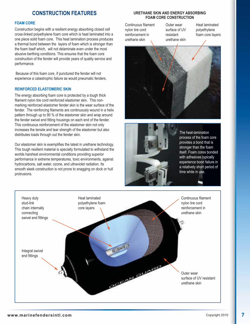
The heat-laminationprocess of the foam coreprovides a bond that isstronger than the foamitself. Foam cores bondedwith adhesives typicallyexperience bond failure ina relatively short period oftime while in use.
URETHANE SKIN AND ENERGY ABSORBINGFOAM CORE CONSTRUCTION
Continuous filamentnylon tire cordreinforcement inurethane skin
Heavy dutystud-linkchain internallyconnectingswivel end fittings
Integral swivelend fittings
Heat laminatedpolyethylene foamcore layers
Continuous filamentnylon tire cordreinforcement inurethane skin
Outer wearsurface of UV resistanturethane skin
Outer wearsurface of UVresistanturethane skin
Heat laminatedpolyethylenefoam core layers
8 www.marinefendersintl .com Copyright 2010
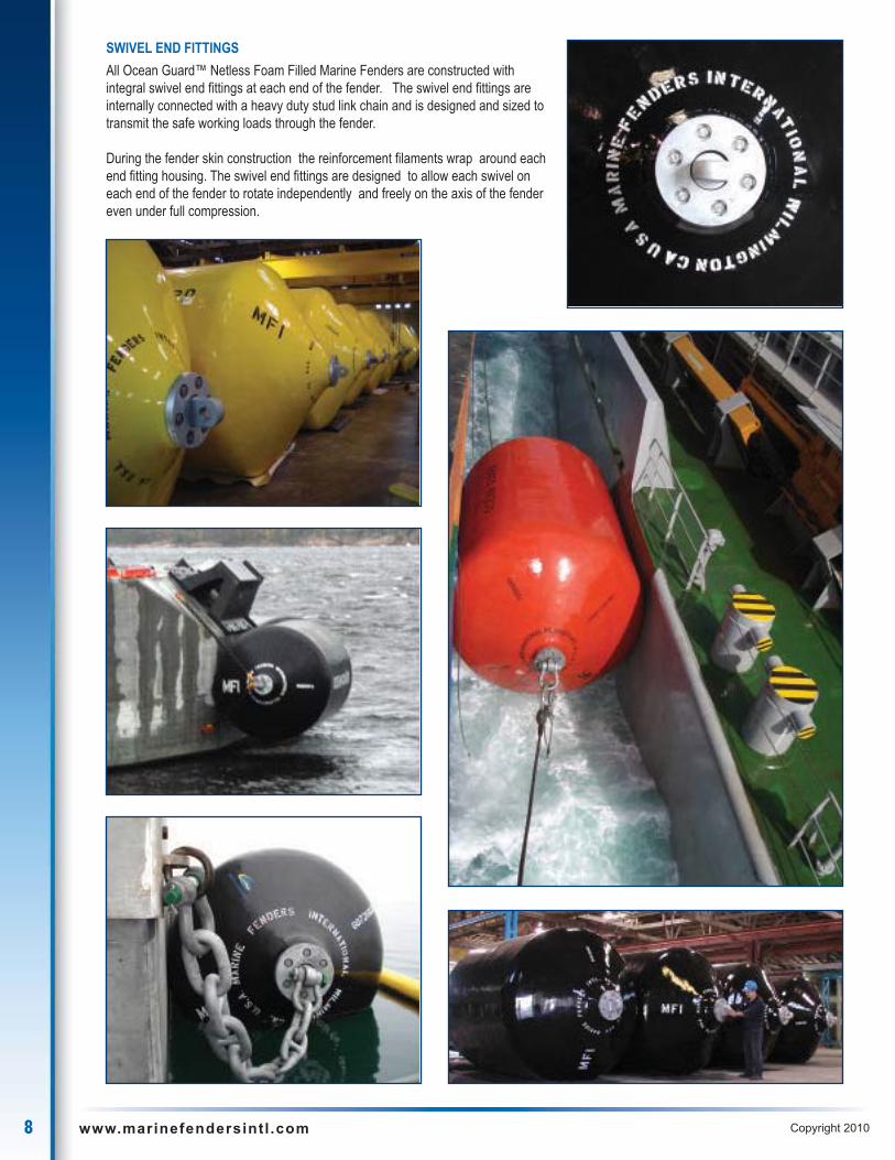
SWIVEL END FITTINGS
All Ocean Guard™ Netless Foam Filled Marine Fenders are constructed withintegral swivel end fittings at each end of the fender. The swivel end fittings areinternally connected with a heavy duty stud link chain and is designed and sized totransmit the safe working loads through the fender.
During the fender skin construction the reinforcement filaments wrap around eachend fitting housing. The swivel end fittings are designed to allow each swivel oneach end of the fender to rotate independently and freely on the axis of the fendereven under full compression.
9www.marinefendersintl .com Copyright 2010
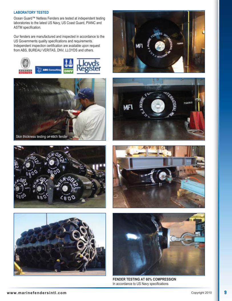
LABORATORY TESTED
Ocean Guard™ Netless Fenders are tested at independent testinglaboratories to the latest US Navy, US Coast Guard, PIANC andASTM specification.
Our fenders are manufactured and inspected in accordance to theUS Governments quality specifications and requirements.Independent inspection certification are available upon requestfrom ABS, BUREAU VERITAS, DNV, LLOYDS and others.
Skin thickness testing on each fender
FENDER TESTING AT 60% COMPRESSIONIn accordance to US Navy specifications

FENDERS LOW REACTION ENHANCED CAPACITY STANDARD CAPACITY ADVANCED CAPACITY HIGH CAPACITY
SIZE ENERGY REACTION ENERGY REACTION ENERGY REACTION ENERGY REACTION ENERGY REACTION
ENGLISH METRIC ABSORPTION FORCE ABSORPTION FORCE ABSORPTION FORCE ABSORPTION FORCE ABSORPTION FORCE
ft x ft m x m ft - kips ton-m kips tons ft - kips ton-m kips tons ft - kips ton-m kips tons ft - kips ton-m kips tons ft - kips ton-m kips tons
2 x 4 0.6 x 1.2 7 1 12 5 9 1 16 7 11 2 20 9 13 2 23 10 14 2 26 12
2 x 6 0.6 x 1.8 11 2 20 9 14 2 26 12 18 3 33 15 21 3 38 17 23 3 43 20
2 x 8 0.6 x 2.4 15 2 28 13 20 3 38 17 25 4 47 21 29 4 54 24 33 5 61 28
2 x 10 0.6 x 3.0 19 3 36 16 26 4 48 22 32 4 60 27 37 5 69 31 42 6 78 35
3 x 5 0.9 x 1.5 19 3 27 12 25 3 36 16 31 4 45 20 36 5 52 23 40 6 59 27
3 x 6 0.9 x 1.8 23 3 29 13 31 4 38 18 39 5 48 22 45 6 55 25 51 7 62 28
3 x 8 0.9 x 2.4 33 5 41 19 44 6 54 25 55 8 68 31 63 9 78 36 72 10 88 40
3 x 10 0.9 x 3.0 43 6 53 24 57 8 70 32 71 10 88 40 82 11 101 46 92 13 114 52
3 x 12 0.9 x 3.7 52 7 65 29 70 10 86 39 87 12 108 49 100 14 124 56 113 16 140 64
3 x 14 0.9 x 4.3 62 8 77 35 82 11 102 46 103 14 128 58 118 16 147 67 134 19 166 75
4 x 6 1.2 x 1.8 36 5 34 16 48 7 45 21 60 8 56 26 69 10 64 30 78 11 73 33
4 x 8 1.2 x 2.4 53 7 50 23 71 10 66 30 89 12 83 38 102 14 95 44 116 16 108 49
4 x 10 1.2 x 3.0 71 10 67 30 94 13 89 40 118 16 111 50 136 18 128 58 153 21 144 65
4 x 12 1.2 x 3.7 88 12 82 37 117 16 109 50 146 20 136 62 168 23 156 71 190 26 177 80
4 x 16 1.2 x 4.9 122 17 113 52 162 22 151 69 203 28 189 86 233 32 217 99 264 37 246 112
4 x 20 1.2 x 6.1 156 22 145 66 208 29 194 88 260 36 242 110 299 41 278 127 338 47 315 143
5 x 8 1.5 x 2.4 81 11 60 27 108 14 80 36 135 18 100 45 155 21 115 52 176 24 130 59
5 x 10 1.5 x 3.0 108 15 80 37 144 20 107 49 180 25 134 61 207 29 154 70 234 32 174 79
5 x 12 1.5 x 3.7 135 19 100 45 180 25 134 60 225 31 167 75 259 36 192 86 293 41 217 98
5 x 14 1.5 x 4.3 161 22 120 55 215 30 160 73 269 37 200 91 309 43 230 105 350 48 260 118
5 x 16 1.5 x 4.9 188 26 140 64 250 34 186 85 313 43 233 106 360 49 268 122 407 56 303 137
5 x 18 1.5 x 5.5 214 29 160 73 286 39 213 97 357 49 266 121 411 56 306 139 464 64 346 157
6 x 12 1.8 x 3.7 180 25 112 50 240 33 149 67 300 41 186 84 345 47 214 97 390 54 242 110
6 x 14 1.8 x 4.3 218 30 135 61 291 40 180 82 364 50 225 102 419 58 259 117 473 65 293 133
6 x 16 1.8 x 4.9 256 35 159 72 342 47 212 96 427 59 265 120 491 68 305 138 555 77 345 156
6 x 18 1.8 x 5.5 295 41 183 83 393 54 244 110 491 68 305 138 565 78 351 159 638 88 397 180
6 x 20 1.8 x 6.1 332 46 206 94 443 62 275 125 554 77 344 156 637 89 396 179 720 100 447 203
7 x 14 2.1 x 4.3 292 40 155 70 390 54 207 94 487 67 259 117 560 77 298 135 633 88 337 153
7 x 16 2.1 x 4.9 344 47 183 83 459 63 244 110 574 79 305 138 660 91 351 159 746 103 397 180
7 x 18 2.1 x 5.5 396 55 211 95 528 73 281 127 660 91 351 159 759 105 404 183 858 119 456 207
7 x 20 2.1 x 6.1 448 62 238 108 598 82 318 144 747 103 397 180 859 118 457 207 971 134 516 234
7 x 22 2.1 x 6.7 500 69 266 121 666 92 354 161 833 115 443 201 958 132 509 231 1083 150 576 261
8 x 12 2.4 x 3.7 319 44 148 67 425 58 197 89 531 73 246 111 611 84 283 128 690 95 320 145
8 x 14 2.4 x 4.3 371 51 173 78 495 68 230 104 619 85 288 130 712 98 331 150 805 111 374 170
8 x 16 2.4 x 4.9 440 61 205 93 586 81 273 124 733 101 341 155 843 116 392 178 953 132 443 201
8 x 18 2.4 x 5.5 508 70 236 107 678 94 315 143 847 117 394 179 974 135 453 206 1101 152 512 232
8 x 20 2.4 x 6.1 577 80 268 122 769 106 358 162 961 133 447 203 1105 153 514 233 1249 173 581 264
8 x 22 2.4 x 6.7 645 89 300 136 860 119 400 182 1075 149 500 227 1236 171 575 261 1398 193 650 295
9 x 14 2.7 x 4.3 467 65 193 88 623 86 258 117 779 108 322 146 896 124 370 168 1012 140 418 190
9 x 16 2.7 x 4.9 534 74 221 100 712 98 294 134 890 123 368 167 1024 141 423 192 1157 160 478 217
9 x 18 2.7 x 5.5 619 86 256 116 826 114 342 155 1032 143 427 194 1187 164 491 223 1342 186 555 252
9 x 20 2.7 x 6.1 705 98 292 132 940 130 389 176 1175 163 486 220 1351 187 559 253 1528 211 632 287
9 x 22 2.7 x 6.7 791 109 327 148 1054 146 436 198 1318 182 545 247 1516 209 627 284 1713 237 709 322
10 x 16 3.0 x 4.9 649 90 241 109 865 120 322 146 1081 150 402 182 1243 173 462 209 1405 194 523 237
10 x 18 3.0 x 5.5 755 104 281 127 1006 139 374 170 1258 174 468 212 1447 200 538 244 1635 226 608 276
10 x 20 3.0 x 6.1 861 119 320 145 1148 158 427 194 1435 198 534 242 1650 228 614 278 1866 258 694 315
10 x 22 3.0 x 6.7 967 134 360 163 1290 178 480 218 1612 223 600 272 1854 256 690 313 2096 290 780 354
10 x 24 3.0 x 7.3 1087 150 404 184 1449 200 539 245 1811 250 674 306 2083 288 775 352 2286 316 850 386
11 x 18 3.4 x 5.5 889 131 301 159 1186 175 401 212 1482 219 501 265 1704 252 576 305 1927 267 651 295
11 x 20 3.4 x 6.1 1018 145 344 167 1357 193 458 223 1696 241 573 279 1950 277 659 321 2141 296 745 338
11 x 22 3.4 x 6.7 1146 158 388 176 1528 211 517 234 1910 264 646 293 2197 304 743 337 2483 343 840 381
11 x 24 3.4 x 7.3 1250 173 422 191 1666 230 563 255 2083 288 704 319 2395 331 810 367 2709 375 916 415
12 x 20 3.7 x 6.1 1298 179 425 193 1730 239 566 257 2163 299 708 321 2487 344 814 369 2812 389 920 417
12 x 24 3.7 x 7.3 1557 215 510 231 2076 286 680 308 2595 358 850 385 2984 412 978 443 3374 467 1105 501
13 x 26 4.0 x 7.9 1944 269 591 268 2592 358 788 358 3240 448 985 447 3726 515 1133 514 4212 583 1281 581
14 x 28 4.3 x 8.5 2400 332 678 308 3200 442 904 410 4000 553 1130 513 4600 636 1300 590 5200 719 1469 665
10 www.marinefendersintl .com Copyright 2010
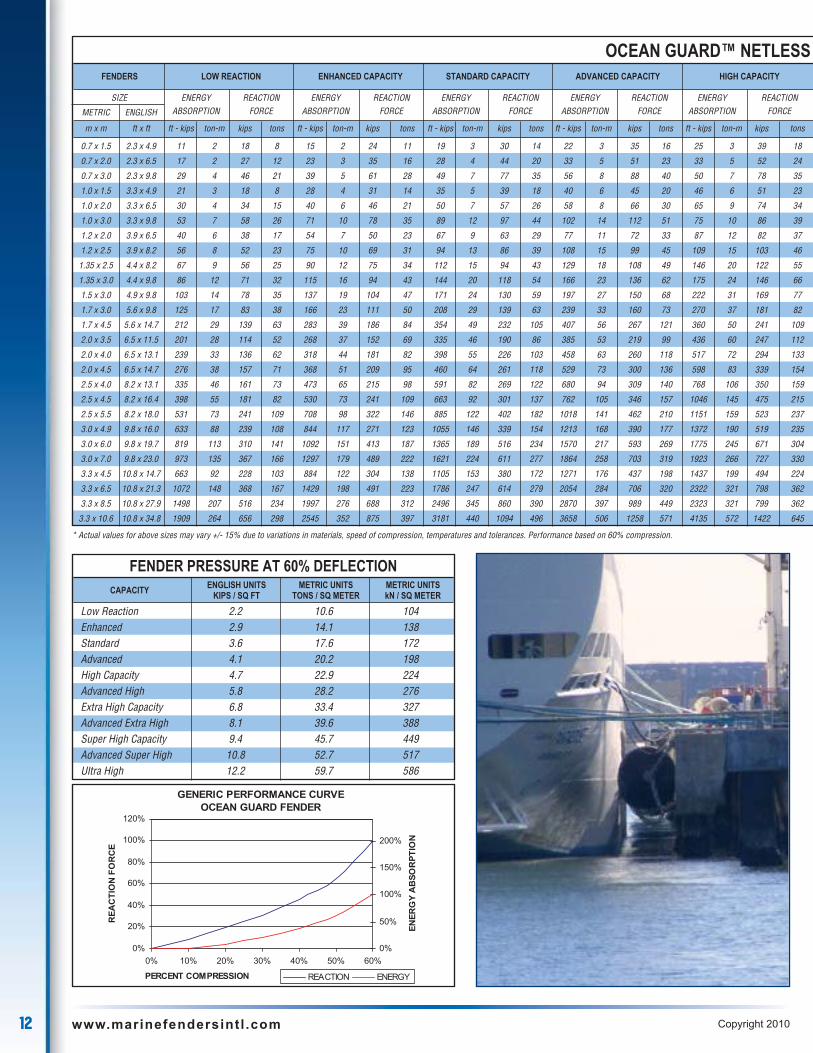
OCEAN GUARD™ NETLESS
* Actual values for above sizes may vary +/- 15% due to variations in materials, speed of compression, temperatures and tolerances. Performance based on 60% compression.
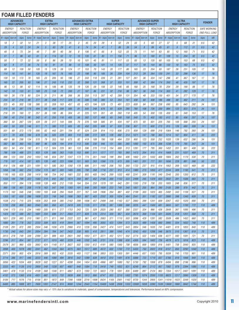
ADVANCED EXTRA ADVANCED EXTRA SUPER ADVANCED SUPER ULTRA FENDERHIGH CAPACITY HIGH CAPACITY HIGH CAPACITY HIGH CAPACITY HIGH CAPACITY HIGH CAPACITY
ENERGY REACTION ENERGY REACTION ENERGY REACTION ENERGY REACTION ENERGY REACTION ENERGY REACTION SAFE WORKINGABSORPTION FORCE ABSORPTION FORCE ABSORPTION FORCE ABSORPTION FORCE ABSORPTION FORCE ABSORPTION FORCE END PULL LOAD
ft - kips ton-m kips tons ft - kips ton-m kips tons ft - kips ton-m kips tons ft - kips ton-m kips tons ft - kips ton-m kips tons ft - kips ton-m kips tons kips kN
18 2 32 14 21 3 38 17 25 3 45 20 29 4 52 24 33 5 60 27 37 5 68 31 9.5 42
29 4 53 24 34 5 63 29 41 6 74 34 47 7 86 39 54 8 99 45 61 9 112 51 9.5 42
40 6 75 34 48 7 89 40 56 8 106 47 65 9 122 55 75 11 141 63 85 12 160 71 9.5 42
51 7 96 43 61 8 114 52 72 10 135 61 83 11 156 71 96 13 180 81 109 15 204 92 9.5 42
50 7 72 32 59 8 86 39 70 10 101 45 81 11 117 53 93 13 135 60 105 15 153 68 9.5 42
62 9 77 35 74 10 91 41 88 12 108 50 101 14 125 57 117 16 144 66 133 18 163 75 9.5 42
88 12 109 50 105 15 129 59 124 17 153 70 143 20 177 80 165 23 204 93 187 26 231 105 17 76
114 16 141 64 135 19 167 76 160 22 198 90 185 26 229 104 213 29 264 120 241 33 299 136 17 76
139 19 173 78 165 23 205 93 196 27 243 110 226 31 281 127 261 36 324 147 296 41 367 167 17 76
165 22 205 93 196 27 243 110 232 32 288 131 268 37 333 151 309 42 384 174 350 48 435 197 17 76
96 13 90 42 114 16 106 48 135 19 126 59 156 22 146 66 180 25 168 78 204 29 190 88 17 76
142 19 133 61 169 23 158 72 200 27 187 86 231 32 216 98 267 36 249 114 303 41 282 129 17 76
189 26 178 80 224 31 211 96 266 36 250 113 307 42 289 131 354 48 333 150 401 54 377 170 17 76
234 32 218 99 277 38 258 117 329 45 306 140 380 53 354 161 438 60 408 186 496 68 462 211 24 107
325 45 302 138 386 53 359 163 457 63 425 194 528 73 491 223 609 84 567 258 690 95 643 292 34 151
416 58 387 176 494 68 460 209 585 81 545 248 676 93 629 285 780 108 726 330 884 122 823 374 34 151
216 29 160 72 257 36 190 86 304 41 225 101 351 49 260 118 405 54 300 135 459 61 340 153 17 76
288 40 214 98 342 47 255 116 405 56 302 137 468 65 348 158 540 75 402 183 612 85 456 207 24 107
360 50 267 120 428 59 317 144 506 70 376 169 585 81 434 197 675 93 501 225 765 105 568 255 24 107
430 59 320 146 511 71 380 172 605 83 450 205 699 97 520 236 807 111 600 273 915 126 680 309 34 151
501 69 373 170 595 82 443 201 704 97 524 239 814 113 606 275 939 129 699 318 1064 146 792 360 34 151
571 78 426 194 678 94 505 229 803 110 599 272 928 128 692 314 1071 147 798 363 1214 167 904 411 50 222
480 66 298 134 570 79 353 160 675 92 419 189 780 108 484 220 900 123 558 252 1020 139 632 286 34 151
582 80 360 163 692 96 428 194 819 113 506 230 946 131 585 265 1092 150 675 306 1238 170 765 347 34 151
683 94 424 192 811 112 504 229 961 133 596 270 1110 154 689 313 1281 177 795 360 1452 201 901 408 50 222
786 109 488 221 933 129 580 263 1105 153 686 311 1277 177 793 360 1473 204 915 414 1669 231 1037 469 70 311
886 123 550 250 1053 146 654 297 1247 173 774 351 1440 199 894 406 1662 231 1032 468 1884 262 1170 530 70 311
779 107 414 187 925 128 492 223 1096 151 583 263 1266 175 673 305 1461 201 777 351 1656 228 881 398 50 222
918 126 488 221 1091 151 580 263 1292 178 686 311 1492 206 793 360 1722 237 915 414 1952 269 1037 469 50 222
1056 146 562 254 1254 173 667 303 1485 205 790 358 1716 237 913 414 1980 273 1053 477 2244 309 1193 541 70 311
1195 165 635 288 1419 196 754 342 1681 232 893 405 1942 269 1032 468 2241 309 1191 540 2540 350 1350 612 70 311
1333 184 709 322 1583 219 842 382 1874 259 997 452 2166 300 1152 523 2499 345 1329 603 2832 391 1506 683 70 311
850 117 394 178 1008 139 468 212 1195 164 554 250 1379 191 642 291 1593 219 738 333 1805 248 836 377 70 311
990 136 461 208 1176 163 547 248 1393 191 648 293 1609 223 749 340 1857 255 864 390 2105 289 979 442 70 311
1173 162 546 248 1393 193 648 294 1649 227 767 349 1906 264 887 402 2199 303 1023 465 2492 343 1159 527 70 311
1355 187 630 286 1609 223 749 340 1906 263 887 403 2202 305 1024 464 2541 351 1182 537 2880 398 1340 609 70 311
1538 213 715 325 1826 253 849 385 2162 299 1006 457 2499 346 1162 527 2883 399 1341 609 3267 452 1520 690 70 311
1720 238 800 363 2043 283 950 431 2419 335 1125 511 2795 387 1300 590 3225 447 1500 681 3655 507 1700 772 110 489
1246 173 515 234 1480 205 611 277 1753 243 725 329 2025 280 837 380 2337 324 966 438 2649 367 1095 496 70 311
1424 197 589 267 1691 234 699 317 2003 277 828 376 2314 320 957 434 2670 369 1104 501 3026 418 1251 568 70 311
1651 229 683 310 1961 271 811 368 2322 322 961 437 2683 371 1110 503 3096 429 1281 582 3509 486 1452 660 70 311
1880 261 778 352 2233 309 923 419 2644 367 1094 495 3055 423 1264 573 3525 489 1458 660 3995 554 1652 748 110 489
2109 291 872 395 2504 346 1036 470 2966 410 1226 556 3427 474 1417 643 3954 546 1635 741 4481 619 1853 840 110 489
1730 240 643 291 2054 284 764 347 2432 338 905 410 2811 389 1045 474 3243 450 1206 546 3675 510 1367 619 70 311
2013 278 749 339 2390 331 889 403 2831 392 1053 477 3271 452 1217 552 3774 522 1404 636 4277 592 1591 721 70 311
2296 317 854 387 2727 377 1015 460 3229 446 1202 545 3731 516 1388 630 4305 594 1602 726 4879 673 1816 823 110 489
2579 357 960 435 3063 424 1140 517 3627 502 1350 612 4191 580 1560 708 4836 669 1800 816 5481 758 2040 925 110 489
2898 400 1078 490 3341 462 1244 564 4075 563 1517 689 4572 632 1702 772 5433 750 2022 918 6157 850 2292 1040 110 489
2371 350 802 424 2816 389 952 432 3335 493 1127 596 3853 533 1303 591 4446 657 1503 795 5039 745 1703 901 110 489
2714 386 917 446 3223 446 1090 494 3816 542 1289 628 4410 610 1491 676 5088 723 1719 837 5766 819 1948 949 110 489
3056 422 1034 469 3629 502 1227 557 4298 594 1454 659 4966 687 1680 762 5730 792 1938 879 6494 898 2196 996 110 489
3333 461 1126 510 3959 548 1338 607 4687 648 1584 718 5418 749 1832 831 6249 864 2112 957 7082 979 2394 1085 110 489
3461 478 1133 514 4109 568 1346 611 4867 673 1593 722 5623 778 1841 835 6489 897 2124 963 7354 1017 2407 1091 110 489
4152 573 1360 616 4931 682 1615 733 5839 806 1913 866 6747 933 2210 1002 7785 1074 2550 1155 8823 1217 2890 1309 110 489
5184 717 1576 715 6156 851 1872 849 7290 1008 2216 1006 8424 1165 2561 1162 9720 1344 2955 1341 11016 1523 3349 1520 110 489
6400 885 1808 821 7600 1051 2147 974 9000 1244 2543 1154 10400 1438 2938 1333 12000 1659 3390 1539 13600 1880 3842 1744 110 489
11www.marinefendersintl .com Copyright 2010
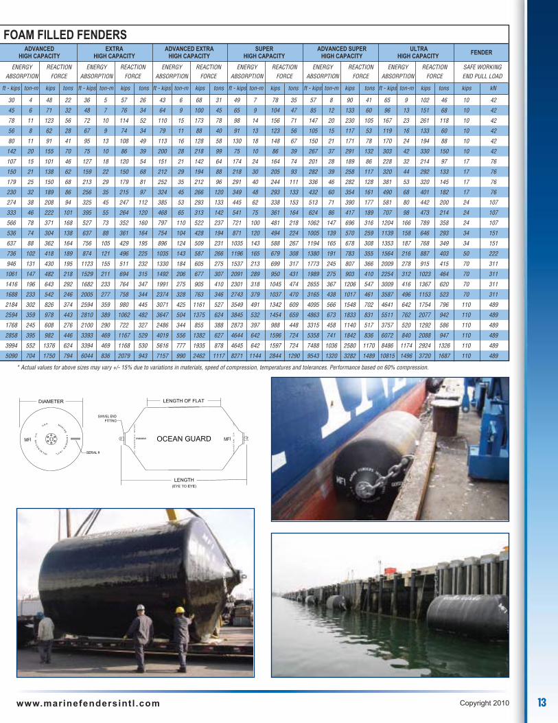
FOAM FILLED FENDERS
* Actual values for above sizes may vary +/- 15% due to variations in materials, speed of compression, temperatures and tolerances. Performance based on 60% compression.
12 www.marinefendersintl .com Copyright 2010
FENDERS LOW REACTION ENHANCED CAPACITY STANDARD CAPACITY ADVANCED CAPACITY HIGH CAPACITY
SIZE ENERGY REACTION ENERGY REACTION ENERGY REACTION ENERGY REACTION ENERGY REACTION
METRIC ENGLISH ABSORPTION FORCE ABSORPTION FORCE ABSORPTION FORCE ABSORPTION FORCE ABSORPTION FORCE
m x m ft x ft ft - kips ton-m kips tons ft - kips ton-m kips tons ft - kips ton-m kips tons ft - kips ton-m kips tons ft - kips ton-m kips tons
0.7 x 1.5 2.3 x 4.9 11 2 18 8 15 2 24 11 19 3 30 14 22 3 35 16 25 3 39 18
0.7 x 2.0 2.3 x 6.5 17 2 27 12 23 3 35 16 28 4 44 20 33 5 51 23 33 5 52 24
0.7 x 3.0 2.3 x 9.8 29 4 46 21 39 5 61 28 49 7 77 35 56 8 88 40 50 7 78 35
1.0 x 1.5 3.3 x 4.9 21 3 18 8 28 4 31 14 35 5 39 18 40 6 45 20 46 6 51 23
1.0 x 2.0 3.3 x 6.5 30 4 34 15 40 6 46 21 50 7 57 26 58 8 66 30 65 9 74 34
1.0 x 3.0 3.3 x 9.8 53 7 58 26 71 10 78 35 89 12 97 44 102 14 112 51 75 10 86 39
1.2 x 2.0 3.9 x 6.5 40 6 38 17 54 7 50 23 67 9 63 29 77 11 72 33 87 12 82 37
1.2 x 2.5 3.9 x 8.2 56 8 52 23 75 10 69 31 94 13 86 39 108 15 99 45 109 15 103 46
1.35 x 2.5 4.4 x 8.2 67 9 56 25 90 12 75 34 112 15 94 43 129 18 108 49 146 20 122 55
1.35 x 3.0 4.4 x 9.8 86 12 71 32 115 16 94 43 144 20 118 54 166 23 136 62 175 24 146 66
1.5 x 3.0 4.9 x 9.8 103 14 78 35 137 19 104 47 171 24 130 59 197 27 150 68 222 31 169 77
1.7 x 3.0 5.6 x 9.8 125 17 83 38 166 23 111 50 208 29 139 63 239 33 160 73 270 37 181 82
1.7 x 4.5 5.6 x 14.7 212 29 139 63 283 39 186 84 354 49 232 105 407 56 267 121 360 50 241 109
2.0 x 3.5 6.5 x 11.5 201 28 114 52 268 37 152 69 335 46 190 86 385 53 219 99 436 60 247 112
2.0 x 4.0 6.5 x 13.1 239 33 136 62 318 44 181 82 398 55 226 103 458 63 260 118 517 72 294 133
2.0 x 4.5 6.5 x 14.7 276 38 157 71 368 51 209 95 460 64 261 118 529 73 300 136 598 83 339 154
2.5 x 4.0 8.2 x 13.1 335 46 161 73 473 65 215 98 591 82 269 122 680 94 309 140 768 106 350 159
2.5 x 4.5 8.2 x 16.4 398 55 181 82 530 73 241 109 663 92 301 137 762 105 346 157 1046 145 475 215
2.5 x 5.5 8.2 x 18.0 531 73 241 109 708 98 322 146 885 122 402 182 1018 141 462 210 1151 159 523 237
3.0 x 4.9 9.8 x 16.0 633 88 239 108 844 117 271 123 1055 146 339 154 1213 168 390 177 1372 190 519 235
3.0 x 6.0 9.8 x 19.7 819 113 310 141 1092 151 413 187 1365 189 516 234 1570 217 593 269 1775 245 671 304
3.0 x 7.0 9.8 x 23.0 973 135 367 166 1297 179 489 222 1621 224 611 277 1864 258 703 319 1923 266 727 330
3.3 x 4.5 10.8 x 14.7 663 92 228 103 884 122 304 138 1105 153 380 172 1271 176 437 198 1437 199 494 224
3.3 x 6.5 10.8 x 21.3 1072 148 368 167 1429 198 491 223 1786 247 614 279 2054 284 706 320 2322 321 798 362
3.3 x 8.5 10.8 x 27.9 1498 207 516 234 1997 276 688 312 2496 345 860 390 2870 397 989 449 2323 321 799 362
3.3 x 10.6 10.8 x 34.8 1909 264 656 298 2545 352 875 397 3181 440 1094 496 3658 506 1258 571 4135 572 1422 645
OCEAN GUARD™ NETLESS
* Actual values for above sizes may vary +/- 15% due to variations in materials, speed of compression, temperatures and tolerances. Performance based on 60% compression.
FENDER PRESSURE AT 60% DEFLECTIONCAPACITY ENGLISH UNITS METRIC UNITS METRIC UNITS
KIPS / SQ FT TONS / SQ METER kN / SQ METER
Low Reaction 2.2 10.6 104Enhanced 2.9 14.1 138Standard 3.6 17.6 172Advanced 4.1 20.2 198High Capacity 4.7 22.9 224Advanced High 5.8 28.2 276Extra High Capacity 6.8 33.4 327Advanced Extra High 8.1 39.6 388Super High Capacity 9.4 45.7 449Advanced Super High 10.8 52.7 517Ultra High 12.2 59.7 586
GENERIC PERFORMANCE CURVEOCEAN GUARD FENDER
0%
20%
40%
60%
80%
100%
120%
0% 10% 20% 30% 40% 50% 60%
PERCENT COMPRESSION
REA
CTI
ON
FOR
CE
0%
50%
100%
150%
200%
ENER
GY
AB
SOR
PTIO
N
REACTION ENERGY
13www.marinefendersintl .com Copyright 2010
30 4 48 22 36 5 57 26 43 6 68 31 49 7 78 35 57 8 90 41 65 9 102 46 10 42
45 6 71 32 48 7 76 34 64 9 100 45 65 9 104 47 85 12 133 60 96 13 151 68 10 42
78 11 123 56 72 10 114 52 110 15 173 78 98 14 156 71 147 20 230 105 167 23 261 118 10 42
56 8 62 28 67 9 74 34 79 11 88 40 91 13 123 56 105 15 117 53 119 16 133 60 10 42
80 11 91 41 95 13 108 49 113 16 128 58 130 18 148 67 150 21 171 78 170 24 194 88 10 42
142 20 155 70 75 10 86 39 200 28 218 99 75 10 86 39 267 37 291 132 303 42 330 150 10 42
107 15 101 46 127 18 120 54 151 21 142 64 174 24 164 74 201 28 189 86 228 32 214 97 17 76
150 21 138 62 159 22 150 68 212 29 194 88 218 30 205 93 282 39 258 117 320 44 292 133 17 76
179 25 150 68 213 29 179 81 252 35 212 96 291 40 244 111 336 46 282 128 381 53 320 145 17 76
230 32 189 86 256 35 215 97 324 45 266 120 349 48 293 133 432 60 354 161 490 68 401 182 17 76
274 38 208 94 325 45 247 112 385 53 293 133 445 62 338 153 513 71 390 177 581 80 442 200 24 107
333 46 222 101 395 55 264 120 468 65 313 142 541 75 361 164 624 86 417 189 707 98 473 214 24 107
566 78 371 168 527 73 352 160 797 110 522 237 721 100 481 218 1062 147 696 316 1204 166 789 358 24 107
536 74 304 138 637 88 361 164 754 104 428 194 871 120 494 224 1005 139 570 259 1139 158 646 293 34 151
637 88 362 164 756 105 429 195 896 124 509 231 1035 143 588 267 1194 165 678 308 1353 187 768 349 34 151
736 102 418 189 874 121 496 225 1035 143 587 266 1196 165 679 308 1380 191 783 355 1564 216 887 403 50 222
946 131 430 195 1123 155 511 232 1330 184 605 275 1537 213 699 317 1773 245 807 366 2009 278 915 415 70 311
1061 147 482 218 1529 211 694 315 1492 206 677 307 2091 289 950 431 1989 275 903 410 2254 312 1023 464 70 311
1416 196 643 292 1682 233 764 347 1991 275 905 410 2301 318 1045 474 2655 367 1206 547 3009 416 1367 620 70 311
1688 233 542 246 2005 277 758 344 2374 328 763 346 2743 379 1037 470 3165 438 1017 461 3587 496 1153 523 70 311
2184 302 826 374 2594 359 980 445 3071 425 1161 527 3549 491 1342 609 4095 566 1548 702 4641 642 1754 796 110 489
2594 359 978 443 2810 389 1062 482 3647 504 1375 624 3845 532 1454 659 4863 673 1833 831 5511 762 2077 942 110 489
1768 245 608 276 2100 290 722 327 2486 344 855 388 2873 397 988 448 3315 458 1140 517 3757 520 1292 586 110 489
2858 395 982 446 3393 469 1167 529 4019 556 1382 627 4644 642 1596 724 5358 741 1842 836 6072 840 2088 947 110 489
3994 552 1376 624 3394 469 1168 530 5616 777 1935 878 4645 642 1597 724 7488 1036 2580 1170 8486 1174 2924 1326 110 489
5090 704 1750 794 6044 836 2079 943 7157 990 2462 1117 8271 1144 2844 1290 9543 1320 3282 1489 10815 1496 3720 1687 110 489
ADVANCED EXTRA ADVANCED EXTRA SUPER ADVANCED SUPER ULTRA FENDERHIGH CAPACITY HIGH CAPACITY HIGH CAPACITY HIGH CAPACITY HIGH CAPACITY HIGH CAPACITY
ENERGY REACTION ENERGY REACTION ENERGY REACTION ENERGY REACTION ENERGY REACTION ENERGY REACTION SAFE WORKINGABSORPTION FORCE ABSORPTION FORCE ABSORPTION FORCE ABSORPTION FORCE ABSORPTION FORCE ABSORPTION FORCE END PULL LOAD
ft - kips ton-m kips tons ft - kips ton-m kips tons ft - kips ton-m kips tons ft - kips ton-m kips tons ft - kips ton-m kips tons ft - kips ton-m kips tons kips kN
FOAM FILLED FENDERS
* Actual values for above sizes may vary +/- 15% due to variations in materials, speed of compression, temperatures and tolerances. Performance based on 60% compression.

14 www.marinefendersintl .com Copyright 2010
E N G I N E E R E D F O R E XC E L L E N C E
P R O V E N A P P L I C A T I O N S
Ferry Terminals
Coast Guard
Navy
Navy
Dredging Operations

15www.marinefendersintl .com Copyright 2010
E N G I N E E R E D F O R E XC E L L E N C E
P R O V E N A P P L I C A T I O N S
Container Terminals
16 www.marinefendersintl .com Copyright 2010
E N G I N E E R E D F O R E XC E L L E N C E
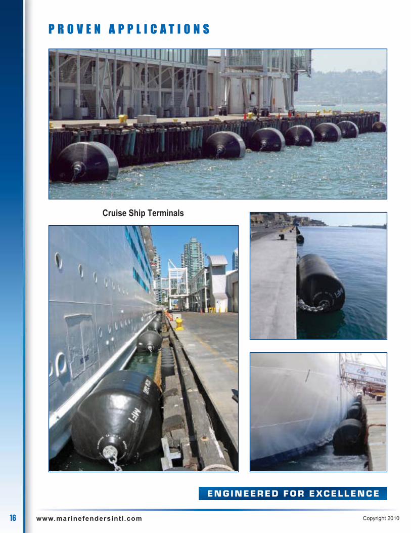
P R O V E N A P P L I C A T I O N S
Cruise Ship Terminals
17www.marinefendersintl .com Copyright 2010
E N G I N E E R E D F O R E XC E L L E N C E
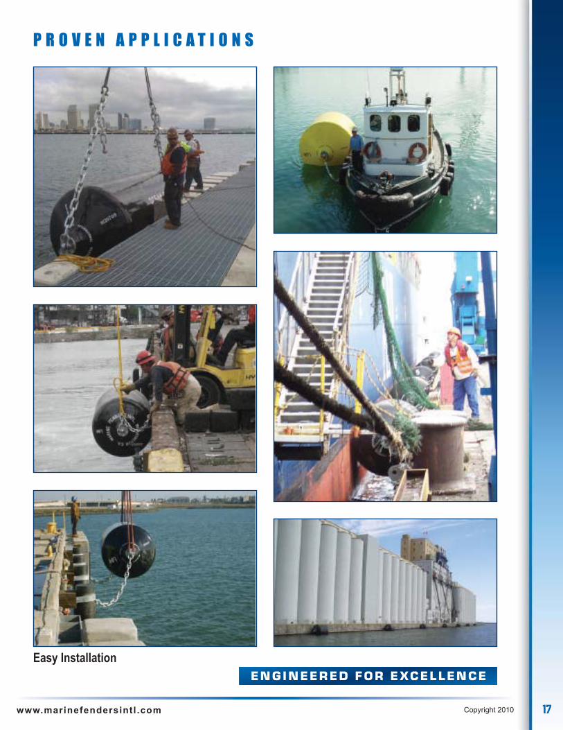
P R O V E N A P P L I C A T I O N S
Easy Installation

18 www.marinefendersintl .com Copyright 2010
OCEAN CUSHION ™ Foam Filled Marine Fenderwith Chain & Aircraft Tire Nets
LOW REACTION FORCE
Ocean Cushion™ Fenders, has the same low reaction force feature as ourOcean Guard ™Fenders producing a smoother, gentler berthing then hardrubber bucking fenders.
The gentle sloping reaction curve of the Ocean Cushion™ foam-filled fendersproduces a lower frequency of peak reaction force or hull pressure duringnormal berthing conditions.
PERFORMANCE FEATURES
HIGH ENERGY ABSORPTION
The foam-filled Ocean Cushion™ Fenders, with chain & aircraft tire nets, aredesigned to provide a high rate of energy absorption with a relatively lowreaction force.
Typically, Ocean Cushion™ foam-filled fenders, when compared to similarsized pneumatic fenders, absorb a greater amount of energy with up to 40%less reaction force.
The foam-filled Ocean Cushion™ Fenders, with chain & aircraft tire nets, are designed to provide a high rate of energy absorption with arelatively low reaction force. Constructed with the same high quality materials and innovative technology as our Ocean Guard ™ Netlessfoam filled fenders, their low maintenance proven design provides reliable performance in today's demanding marine environments.
LARGE STANDOFF
Ocean Cushion™ Fenders can provide a standoff unmatched bymany fendering systems. The chain & aircraft tire nets increase thediameter of the fender body achieving a standoff of up to 16 ft.
LOW MAINTENANCE
Unlike pneumatic fenders, Ocean Cushion™ foam-filledfenders are not inflated with air. The foam filled constructionrequires no air pressure or safety valves to maintain.
RELIABLE AND SAFE PERFORMANCE
The closed cell foam core construction of Ocean Cushion™Fenders insure that the fender will perform even when it is cutor punctured, when you need it most. It will not deflate likepneumatic fenders.
19www.marinefendersintl .com Copyright 2010
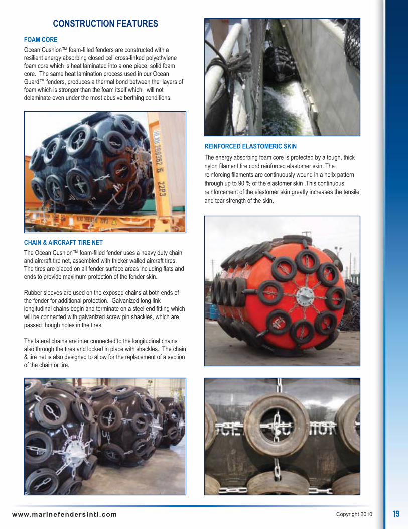
CONSTRUCTION FEATURES
FOAM CORE
Ocean Cushion™ foam-filled fenders are constructed with aresilient energy absorbing closed cell cross-linked polyethylenefoam core which is heat laminated into a one piece, solid foamcore. The same heat lamination process used in our OceanGuard™ fenders, produces a thermal bond between the layers offoam which is stronger than the foam itself which, will notdelaminate even under the most abusive berthing conditions.
CHAIN & AIRCRAFT TIRE NET
The Ocean Cushion™ foam-filled fender uses a heavy duty chainand aircraft tire net, assembled with thicker walled aircraft tires.The tires are placed on all fender surface areas including flats andends to provide maximum protection of the fender skin.
Rubber sleeves are used on the exposed chains at both ends ofthe fender for additional protection. Galvanized long linklongitudinal chains begin and terminate on a steel end fitting whichwill be connected with galvanized screw pin shackles, which arepassed though holes in the tires.
The lateral chains are inter connected to the longitudinal chainsalso through the tires and locked in place with shackles. The chain& tire net is also designed to allow for the replacement of a sectionof the chain or tire.
REINFORCED ELASTOMERIC SKIN
The energy absorbing foam core is protected by a tough, thicknylon filament tire cord reinforced elastomer skin. Thereinforcing filaments are continuously wound in a helix patternthrough up to 90 % of the elastomer skin .This continuousreinforcement of the elastomer skin greatly increases the tensileand tear strength of the skin.

20 www.marinefendersintl .com Copyright 2010
** ACTUAL VALUES FOR ABOVE SIZES MAY VARY +/- 15% DUE TO VARIATIONS IN MATERIALS, SPEED OF COMPRESSION,TEMPERATURES AND TOLERANCES.
Ocean Cushion foam filled fenders are also available in other sizes and capacity models,Low Reaction, High, Extra High, and Super High Capacity.
OCEAN CUSHION™ STANDARD CAPACITY FOAM FILLED FENDERSWITH CHAIN & AIRCRAFT TIRE NETS
ENGLISH SIZES
FENDERS STAND OFF STANDARD CAPACITY HIGH CAPACITYSIZE DIAMETER ENERGY REACTION ENERGY REACTION
ENGLISH METRIC UNCOMPRESSED ABSORPTION FORCE ABSORPTION FORCEft x ft m x m ft m ft - kips ton-m kips tons ft - kips ton-m kips tons
3 x 6 0.92 x 1.83 4.1 1.2 36 5 55 25 52 7 79 36
4 x 6 1.22 x1.83 5.3 1.6 65 9 72 33 94 13 103 47
4 x 8 1.22 x 2.44 5.3 1.6 85 12 98 44 123 17 138 63
5 x 10 1.53 x 3.05 6.5 2.0 165 23 152 69 239 33 214 97
5 x 16 1.53 x 4.88 6.5 2.0 259 36 240 109 375 52 338 153
6 x 12 1.83 x 3.66 7.5 2.3 295 41 217 98 428 59 306 139
7 x 14 2.13 x 4.27 8.5 2.6 450 62 260 118 652 90 366 166
8 x 12 2.44 x 3.66 9.8 3.0 465 64 268 122 674 93 377 171
8 x 16 2.44 x 4.88 9.8 3.0 662 92 380 172 959 133 535 243
9 x 14 2.75 x 4.27 10.8 3.3 730 101 373 169 1058 146 525 238
9 x 18 2.75 x 5.49 10.8 3.3 937 130 480 218 1358 188 676 307
10 x 16 3.05 x 4.88 11.8 3.6 976 135 450 204 1414 196 634 287
10 x 20 3.05 x 6.10 11.8 3.6 1,286 178 590 268 1864 258 831 377
11 x 18 3.35 x 5.49 12.8 3.9 1,386 192 581 264 2009 278 818 371
11 x 22 3.35 x 6.71 12.8 3.9 1,697 235 711 323 2459 340 1001 454
12 x 24 3.70 x 7.30 13.8 4.2 2,196 304 844 383 3183 440 1189 539
13 x 26 3.96 x 7.90 14.8 4.5 2,785 385 987 448 4036 558 1390 631
14 x 28 4.27 x 8.53 15.8 4.8 3,421 473 1,128 512 4958 686 1589 721
METRIC SIZES
FENDERS STAND OFF STANDARD CAPACITY HIGH CAPACITYSIZE DIAMETER ENERGY REACTION ENERGY REACTION
METRIC ENGLISH UNCOMPRESSED ABSORPTION FORCE ABSORPTION FORCEm x m ft x ft ft m ft - kips ton-m kips tons ft - kips ton-m kips tons
1.00 x 1.50 3.3 x 4.9 4.4 1.3 35 5 50 23 50 7 71 32
1.00 x 2.00 3.3 x 6.6 4.4 1.3 49 7 67 30 71 10 96 43
1.20 x 2.00 3.9 x 6.6 5.3 1.6 64 9 76 34 93 13 107 49
1.20 x 2.50 3.9 x 8.2 5.3 1.6 80 11 94 43 116 16 132 60
1.35 x 2.50 4.4 x 8.2 5.9 1.8 103 14 108 49 150 21 152 69
1.35 x 4.00 4.4 x 13.1 5.9 1.8 165 23 172 78 239 33 242 110
1.50 x 3.00 4.9 x 9.8 6.4 2.0 156 22 146 66 226 31 206 93
1.70 x 3.00 5.6 x 9.8 7.1 2.2 196 27 162 73 284 39 227 103
1.70 x 4.50 5.6 x 14.8 7.1 2.2 297 41 244 111 430 60 344 156
2.00 x 3.50 6.6 x 11.5 8.1 2.5 318 44 222 101 461 64 313 142
2.00 x 4.00 6.6 x 13.1 8.1 2.5 371 51 259 117 538 74 365 165
2.20 x 4.50 7.2 x 14.8 8.7 2.7 500 69 321 146 725 100 452 205
2.20 x 5.50 7.2 x 18.0 8.7 2.7 609 84 390 177 883 122 549 249
2.50 x 4.00 8.2 x 13.1 10.0 3.0 542 75 305 138 786 109 430 195
2.50 x 5.50 8.2 x 18.0 10.0 3.0 793 110 447 203 1149 159 629 285
3.00 x 6.00 9.8 x 19.7 11.6 3.5 1,213 168 571 259 1758 243 804 365
3.30 x 4.50 10.8 x 14.8 12.6 3.8 1,010 140 430 195 1464 202 606 275
3.30 x 6.50 10.8 x 21.3 12.6 3.8 1,581 219 675 306 2291 317 951 431
3.30 x 10.6 10.8 x 34.8 12.6 3.8 2,774 384 1,185 538 4020 556 1669 757
4.20 x 8.40 13.8 x 27.6 15.6 4.8 3,325 460 1,110 503 4819 666 1563 709
PERFORMANCE AT 60% COMPRESSION
PERFORMANCE AT 60% COMPRESSION
21www.marinefendersintl .com Copyright 2010
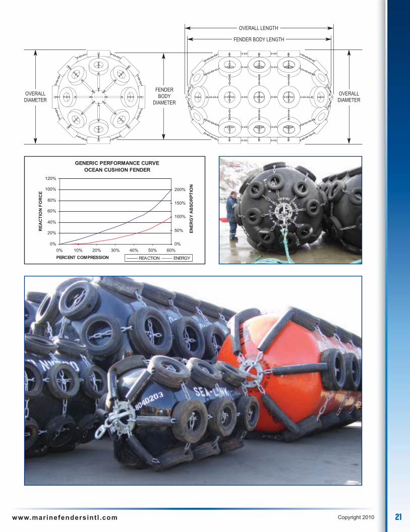
GENERIC PERFORMANCE CURVEOCEAN CUSHION FENDER
0%
20%
40%
60%
80%
100%
120%
0% 10% 20% 30% 40% 50% 60%PERCENT COMPRESSION
REA
CTI
ON
FOR
CE
0%
50%
100%
150%
200%EN
ERG
YA
BSO
RPT
ION
REACTION ENERGY
OVERALLDIAMETER
OVERALLDIAMETER
FENDERBODY
DIAMETER
OVERALL LENGTH
FENDER BODY LENGTH

22 www.marinefendersintl .com Copyright 2010
E N G I N E E R E D F O R E XC E L L E N C E
P R O V E N A P P L I C A T I O N S
23www.marinefendersintl .com Copyright 2010
E N G I N E E R E D F O R E XC E L L E N C E
P R O V E N A P P L I C A T I O N S
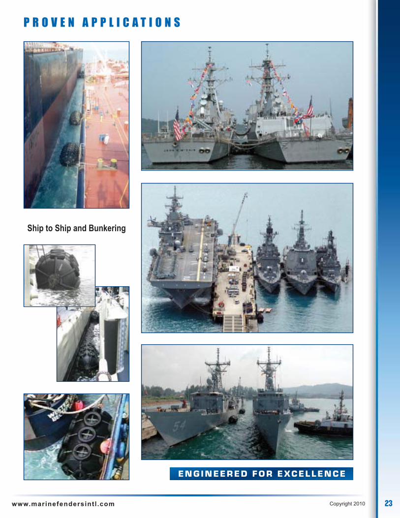
Ship to Ship and Bunkering

24 www.marinefendersintl .com Copyright 2010
Marine Fenders International, Inc. Ocean Guard ™ Small Standard Duty (SSD) & Ocean Guard ™ Small Standard Duty with Hawse Pipefitting (SSD-HP) foam filled marine fenders are designed for quick and convenient use. SSD fenders compact sizes are ideal for thelimited storage space available on board of Naval and Commercial Vessels. Their lightweight allows for easy installation and can behandled by one or two people.
OCEAN GUARD ™ Small Standard Duty Foam Filled Fender
OCEAN GUARD ™ SMALL STANDARD DUTY (SSD)
SSD fenders are constructed in accordance with US NavyTechnical Specifications. They are built with the same qualityconstruction and materials as OCEAN GUARD ™ fenders.
• Lightweight heat laminated closed cell resilient energyabsorbing foam core
• Tough non-marking nylon Tire Cord reinforced urethaneelastomeric skin
• Integral end fittings either stainless steel or galvanized• Optional internal through chain
DIAM
ETER
LENGTH
Pad-eye end fittingsinternally connected
with a chain
Continuous filamentnylon tire cord
reinforcement inurethane skin
25www.marinefendersintl .com Copyright 2010
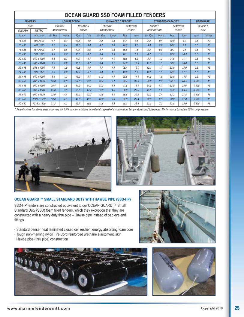
OCEAN GUARD ™ SMALL STANDARD DUTY WITH HAWSE PIPE (SSD-HP)
SSD-HP fenders are constructed equivalent to our OCEAN GUARD ™ SmallStandard Duty (SSD) foam filled fenders, which they exception that they areconstructed with a heavy duty thru pipe – Hawse pipe instead of pad eye endfittings.
• Standard denser heat laminated closed cell resilient energy absorbing foam core• Tough non-marking nylon Tire Cord reinforced urethane elastomeric skin• Hawse pipe (thru pipe) construction
OCEAN GUARD SSD FOAM FILLED FENDERSFENDERS LOW REACTION ENHANCED CAPACITY STANDARD CAPACITY HARDWARE
SIZE ENERGY REACTION ENERGY REACTION ENERGY REACTION SHACKLE
ENGLISH METRIC ABSORPTION FORCE ABSORPTION FORCE ABSORPTION FORCE SIZE
in x in mm x mm ft - kips ton-m kips tons ft - kips ton-m kips tons ft - kips ton-m kips tons tons inches
16 x 24 400 x 600 1.7 0.2 10.8 4.9 2.2 0.3 14.4 6.5 2.8 0.4 18.0 8.2 0.5 13
16 x 36 400 x 900 3.2 0.4 12.0 5.4 4.2 0.6 16.0 7.3 5.3 0.7 20.0 9.1 0.5 13
18 x 36 457 x 900 4.1 0.6 12.4 5.6 5.4 0.8 16.6 7.5 6.8 0.9 20.7 9.4 0.5 13
20 x 36 500 x 900 4.9 0.7 13.6 6.2 6.6 0.9 18.1 8.2 8.2 1.1 22.6 10.3 0.5 13
20 x 39 500 x 1000 5.3 0.7 14.7 6.7 7.0 1.0 19.6 8.9 8.8 1.2 24.5 11.1 0.5 13
20 x 48 500 x 1200 6.6 0.9 18.0 8.2 8.8 1.2 24.0 10.9 11.0 1.5 30.0 13.6 0.5 13
22 x 48 558 x 1200 7.3 1.0 19.8 9.0 9.8 1.3 26.4 12.0 12.2 1.7 33.0 15.0 0.5 13
24 x 36 600 x 900 6.3 0.9 14.7 6.7 8.4 1.2 19.6 8.9 10.5 1.5 24.5 11.1 0.5 13
24 x 48 600 x 1200 8.4 1.2 19.2 8.7 11.2 1.5 25.6 11.6 14.0 1.9 32.0 14.5 0.5 13
32 x 50 800 x 1270 16.8 2.3 64.8 29.1 22.4 3.1 86.4 38.8 28.0 3.9 108.0 48.5 0.625 16
36 x 48 900 x 1200 20.4 2.8 31.2 14.2 27.2 3.8 41.6 18.9 34.0 4.7 52.0 23.6 0.625 16
36 x 60 900 x 1500 25.0 3.5 39.0 17.7 33.3 4.6 52.0 23.6 41.6 5.8 65.0 29.5 0.625 16
36 x 72 900 x 1828 32.0 4.4 50.0 22.7 42.6 5.9 66.6 30.2 53.3 7.4 83.3 37.8 0.625 16
39 x 60 1000 x 1500 30.0 4.1 42.0 19.1 40.0 5.5 56.0 25.4 50.0 6.9 70.0 31.8 0.625 16
40 x 60 1016 x 1500 31.2 4.3 43.7 19.8 41.6 5.8 58.2 26.4 52.0 7.2 72.8 33.0 0.625 16
* Actual values for above sizes may vary +/- 15% due to variations in materials, speed of compression, temperatures and tolerances. Performance based on 60% compression.
26 www.marinefendersintl .com Copyright 2010
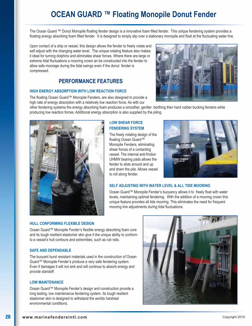
The Ocean Guard ™ Donut Monopile floating fender design is a innovative foam filled fender. This unique fendering system provides afloating energy absorbing foam filled fender. It is designed to simply slip over a stationary monopile and float at the fluctuating water line.
OCEAN GUARD ™ Floating Monopile Donut Fender
LOW SHEAR FORCEFENDERING SYSTEM
The freely rotating design of thefloating Ocean Guard™Monopile Fenders, eliminatingshear forces of a contactingvessel. The internal anti-frictionUHMW bearing pads allows thefender to slide around and upand down the pile. Allows vesselto roll along fender.
SELF ADJUSTING WITH WATER LEVEL & ALL TIDE MOORING
Ocean Guard™ Monopile Fender’s buoyancy allows it to freely float with waterlevels, maintaining optimal fendering. With the addition of a mooring crown thisunique feature provides all tide mooring. This eliminates the need for frequentmooring line adjustments during tidal fluctuations.
Upon contact of a ship or vessel, this design allows the fender to freely rotate andself adjust with the changing water level. The unique rotating feature also makesit ideal for turning dolphins and eliminates shear forces. Where there are large orextreme tidal fluctuations a mooring crown an be constructed into the fender toallow safe moorage during the tidal swings even if the donut fender iscompressed.
HULL CONFORMING FLEXIBLE DESIGN
Ocean Guard™ Monopile Fender’s flexible energy absorbing foam coreand its tough resilient elastomer skin give it the unique ability to conformto a vessel’s hull contours and extremities, such as rub rails.
SAFE AND DEPENDABLE
The buoyant burst resistant materials used in the construction of OceanGuard™ Monopile Fender’s produce a very safe fendering system.Even if damages it will not sink and will continue to absorb energy andprovide standoff.
LOW MAINTENANCE
Ocean Guard™ Monopile Fender’s design and construction provide along lasting, low maintenance fendering system. Its tough resilientelastomer skin is designed to withstand the worlds harshestenvironmental conditions.
PERFORMANCE FEATURES
HIGH ENERGY ABSORPTION WITH LOW REACTION FORCE
The floating Ocean Guard™ Monopile Fenders, are also designed to provide ahigh rate of energy absorption with a relatively low reaction force. As with ourother fendering systems the energy absorbing foam produces a smoother, gentler berthing then hard rubber bucking fenders whileproducing low reaction forces. Additional energy absorption is also supplied by the piling.

27www.marinefendersintl .com Copyright 2010
CONSTRUCTION FEATURES
FOAM CORE
The floating Ocean Guard™ Monopile Fenders are also constructed with aresilient energy absorbing 100% closed cell cross-linked polyethylene foamcore which is heat laminated into a one piece, solid foam core. The sameheat lamination process used in our Ocean Guard™ fenders, produces athermal bond between the layers of foam which is stronger than the foamitself which, will not delaminate even under the most abusive berthingconditions. Additionally, a number of foam variations are available for eachsize which provide higher capacity fenders.
HEAVY DUTY INTERNAL STRUCTURAL STEEL CORE
The internal steel core of the Ocean Guard Monopile Donut fenderis the foundation of the fender. Affixed to this heavy duty fabricated steel structureare the components of the fender, energy absorbing foam core, reinforcedelastomer skin, UHMW anti-friction bearing pads an optional mooring crown.
REINFORCED ELASTOMERIC SKIN
The energy absorbing foam core is protected by a tough, thick nylon filamenttire cord reinforced elastomer skin. The reinforcing filaments are continuouslywound in a helix pattern through up to 90 % of the elastomer skin .Thiscontinuous reinforcement of the elastomer skin greatly increases the tensileand tear strength of the skin. The elastomer skin is non-marking and highlyresistant to environmental hazards such as ozone and ultra-violet radiation.
ANTI-FRICTION BEARING PADS
The internal anti - friction UHMW bearing padsallows the fender to slide around and up and downthe pile. Their special design prevents the fenderfrom binding. Each anti-friction bearing pad ismachined to the radius of internal steel core and todiameter of the central piling. The anti-frictionbearing pads are designed to easily be replaced ifneeded.
Heat laminatedpolyethylene foamcore layers
Pile
Continuous filamentnylon tire cordreinforcement inurethane skin
Outer wearsurface of UVresistanturethane skin
Inner Steel CoreAnti-FrictionBearing Pads

28 www.marinefendersintl .com Copyright 2010
APPLICATIONS
DESIGN
The basic design principle of the floating Ocean Guard™Monopile Fender is to provide a innovative fenderingsystem that absorbs energy, adjust to tidal fluctuations andeliminates shear forces.
The ability of this fendering system to freely ride up anddown and rotate around the driven stationary central steelpile even under compression achieves this design goal.
The proven performance and versatility of the OceanGuard™ Monopile Fendering System make it ideal thetoughest mooring applications.
APPLICATIONS
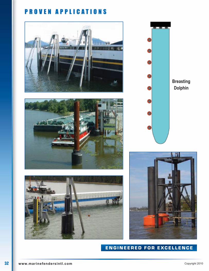
• Breasting Dolphins• Bridge protection• Corner protection• Dock fendering where large tidal changes occur• Dock fendering where vessels need roll along fenders for loading• Ferry vessel applications• Lock entrance• Turning dolphin applications
CUSTOM DESIGNS
As the worlds commerce gets smaller higher demands on portsand vessels are made to provide safer berthing operations. TheOcean Guard™ Donut Monopile fender reduces ship, vesseland dock maintenance costs. Marine Fenders International, Inc.works closely with the customer to design a custom OceanGuard™ Donut Monopile foam filled fender that is specific totheir needs in size, shape, and color.
29www.marinefendersintl .com Copyright 2010
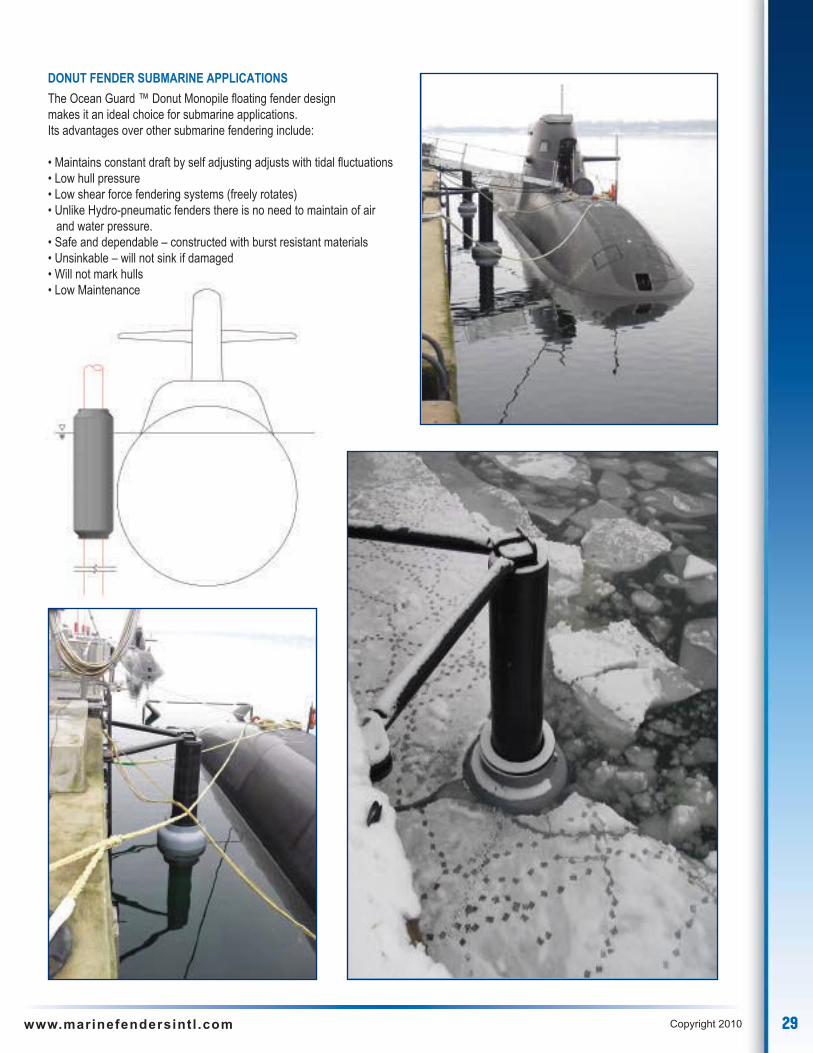
DONUT FENDER SUBMARINE APPLICATIONS
The Ocean Guard ™ Donut Monopile floating fender designmakes it an ideal choice for submarine applications.Its advantages over other submarine fendering include:
• Maintains constant draft by self adjusting adjusts with tidal fluctuations• Low hull pressure• Low shear force fendering systems (freely rotates)• Unlike Hydro-pneumatic fenders there is no need to maintain of air
and water pressure.• Safe and dependable – constructed with burst resistant materials• Unsinkable – will not sink if damaged• Will not mark hulls• Low Maintenance
30 www.marinefendersintl .com Copyright 2010
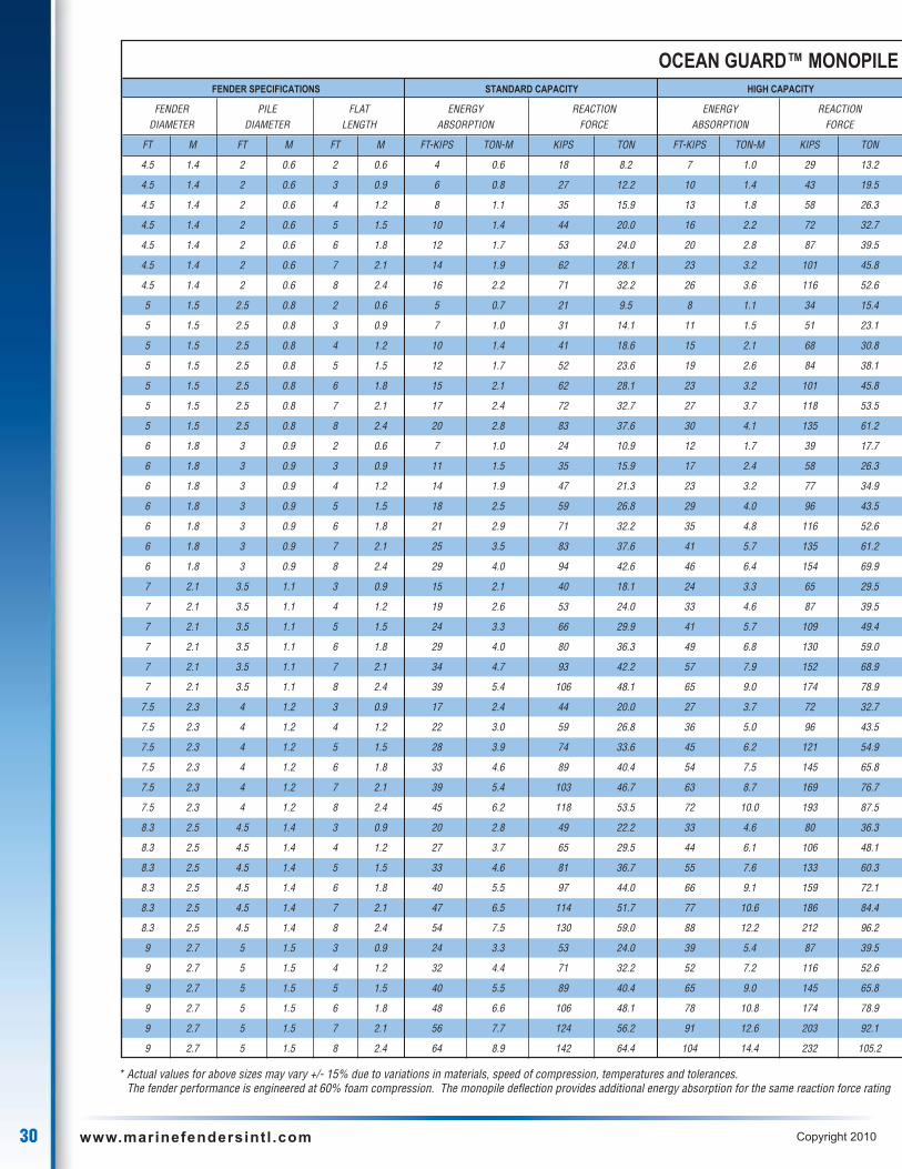
OCEAN GUARD™ MONOPILEFENDER SPECIFICATIONS STANDARD CAPACITY HIGH CAPACITY
FENDER PILE FLAT ENERGY REACTION ENERGY REACTIONDIAMETER DIAMETER LENGTH ABSORPTION FORCE ABSORPTION FORCE
FT M FT M FT M FT-KIPS TON-M KIPS TON FT-KIPS TON-M KIPS TON
4.5 1.4 2 0.6 2 0.6 4 0.6 18 8.2 7 1.0 29 13.2
4.5 1.4 2 0.6 3 0.9 6 0.8 27 12.2 10 1.4 43 19.5
4.5 1.4 2 0.6 4 1.2 8 1.1 35 15.9 13 1.8 58 26.3
4.5 1.4 2 0.6 5 1.5 10 1.4 44 20.0 16 2.2 72 32.7
4.5 1.4 2 0.6 6 1.8 12 1.7 53 24.0 20 2.8 87 39.5
4.5 1.4 2 0.6 7 2.1 14 1.9 62 28.1 23 3.2 101 45.8
4.5 1.4 2 0.6 8 2.4 16 2.2 71 32.2 26 3.6 116 52.6
5 1.5 2.5 0.8 2 0.6 5 0.7 21 9.5 8 1.1 34 15.4
5 1.5 2.5 0.8 3 0.9 7 1.0 31 14.1 11 1.5 51 23.1
5 1.5 2.5 0.8 4 1.2 10 1.4 41 18.6 15 2.1 68 30.8
5 1.5 2.5 0.8 5 1.5 12 1.7 52 23.6 19 2.6 84 38.1
5 1.5 2.5 0.8 6 1.8 15 2.1 62 28.1 23 3.2 101 45.8
5 1.5 2.5 0.8 7 2.1 17 2.4 72 32.7 27 3.7 118 53.5
5 1.5 2.5 0.8 8 2.4 20 2.8 83 37.6 30 4.1 135 61.2
6 1.8 3 0.9 2 0.6 7 1.0 24 10.9 12 1.7 39 17.7
6 1.8 3 0.9 3 0.9 11 1.5 35 15.9 17 2.4 58 26.3
6 1.8 3 0.9 4 1.2 14 1.9 47 21.3 23 3.2 77 34.9
6 1.8 3 0.9 5 1.5 18 2.5 59 26.8 29 4.0 96 43.5
6 1.8 3 0.9 6 1.8 21 2.9 71 32.2 35 4.8 116 52.6
6 1.8 3 0.9 7 2.1 25 3.5 83 37.6 41 5.7 135 61.2
6 1.8 3 0.9 8 2.4 29 4.0 94 42.6 46 6.4 154 69.9
7 2.1 3.5 1.1 3 0.9 15 2.1 40 18.1 24 3.3 65 29.5
7 2.1 3.5 1.1 4 1.2 19 2.6 53 24.0 33 4.6 87 39.5
7 2.1 3.5 1.1 5 1.5 24 3.3 66 29.9 41 5.7 109 49.4
7 2.1 3.5 1.1 6 1.8 29 4.0 80 36.3 49 6.8 130 59.0
7 2.1 3.5 1.1 7 2.1 34 4.7 93 42.2 57 7.9 152 68.9
7 2.1 3.5 1.1 8 2.4 39 5.4 106 48.1 65 9.0 174 78.9
7.5 2.3 4 1.2 3 0.9 17 2.4 44 20.0 27 3.7 72 32.7
7.5 2.3 4 1.2 4 1.2 22 3.0 59 26.8 36 5.0 96 43.5
7.5 2.3 4 1.2 5 1.5 28 3.9 74 33.6 45 6.2 121 54.9
7.5 2.3 4 1.2 6 1.8 33 4.6 89 40.4 54 7.5 145 65.8
7.5 2.3 4 1.2 7 2.1 39 5.4 103 46.7 63 8.7 169 76.7
7.5 2.3 4 1.2 8 2.4 45 6.2 118 53.5 72 10.0 193 87.5
8.3 2.5 4.5 1.4 3 0.9 20 2.8 49 22.2 33 4.6 80 36.3
8.3 2.5 4.5 1.4 4 1.2 27 3.7 65 29.5 44 6.1 106 48.1
8.3 2.5 4.5 1.4 5 1.5 33 4.6 81 36.7 55 7.6 133 60.3
8.3 2.5 4.5 1.4 6 1.8 40 5.5 97 44.0 66 9.1 159 72.1
8.3 2.5 4.5 1.4 7 2.1 47 6.5 114 51.7 77 10.6 186 84.4
8.3 2.5 4.5 1.4 8 2.4 54 7.5 130 59.0 88 12.2 212 96.2
9 2.7 5 1.5 3 0.9 24 3.3 53 24.0 39 5.4 87 39.5
9 2.7 5 1.5 4 1.2 32 4.4 71 32.2 52 7.2 116 52.6
9 2.7 5 1.5 5 1.5 40 5.5 89 40.4 65 9.0 145 65.8
9 2.7 5 1.5 6 1.8 48 6.6 106 48.1 78 10.8 174 78.9
9 2.7 5 1.5 7 2.1 56 7.7 124 56.2 91 12.6 203 92.1
9 2.7 5 1.5 8 2.4 64 8.9 142 64.4 104 14.4 232 105.2
* Actual values for above sizes may vary +/- 15% due to variations in materials, speed of compression, temperatures and tolerances.The fender performance is engineered at 60% foam compression. The monopile deflection provides additional energy absorption for the same reaction force rating

31www.marinefendersintl .com Copyright 2010
DONUT FLOATING FENDEREXTRA HIGH CAPACITY SUPER HIGH CAPACITY ULTRA HIGH CAPACITY
ENERGY REACTION ENERGY REACTION ENERGY REACTIONABSORPTION FORCE ABSORPTION FORCE ABSORPTION FORCE
FT-KIPS TON-M KIPS TON FT-KIPS TON-M KIPS TON FT-KIPS TON-M KIPS TON
10 1.4 44 20.0 15 2.1 66 29.9 20 2.8 90 40.8
15 2.1 66 29.9 22 3.0 99 44.9 30 4.1 135 61.2
20 2.8 88 39.9 30 4.1 132 59.9 40 5.5 180 81.6
25 3.5 110 49.9 37 5.1 165 74.8 51 7.1 225 102.1
30 4.1 132 59.9 44 6.1 198 89.8 61 8.4 270 122.5
35 4.8 154 69.9 52 7.2 230 104.3 71 9.8 315 142.9
40 5.5 176 79.8 59 8.2 263 119.3 81 11.2 360 163.3
12 1.7 51 23.1 17 2.4 77 34.9 24 3.3 105 47.6
17 2.4 77 34.9 26 3.6 115 52.2 35 4.8 157 71.2
23 3.2 103 46.7 35 4.8 154 69.9 47 6.5 210 95.3
29 4.0 128 58.1 43 5.9 192 87.1 59 8.2 262 118.8
35 4.8 154 69.9 52 7.2 230 104.3 71 9.8 315 142.9
40 5.5 180 81.6 60 8.3 269 122.0 83 11.5 367 166.5
46 6.4 205 93.0 69 9.5 307 139.3 94 13.0 419 190.1
18 2.5 59 26.8 26 3.6 88 39.9 36 5.0 120 54.4
26 3.6 88 39.9 40 5.5 132 59.9 54 7.5 180 81.6
35 4.8 117 53.1 53 7.3 176 79.8 72 10.0 240 108.9
44 6.1 147 66.7 66 9.1 219 99.3 90 12.4 300 136.1
53 7.3 176 79.8 79 10.9 263 119.3 108 14.9 360 163.3
62 8.6 205 93.0 92 12.7 307 139.3 126 17.4 419 190.1
70 9.7 234 106.1 105 14.5 351 159.2 144 19.9 479 217.3
37 5.1 99 44.9 56 7.7 148 67.1 76 10.5 202 91.6
49 6.8 132 59.9 74 10.2 198 89.8 101 14.0 270 122.5
62 8.6 165 74.8 93 12.9 247 112.0 126 17.4 337 152.9
74 10.2 198 89.8 111 15.4 296 134.3 152 21.0 404 183.3
87 12.0 231 104.8 130 18.0 346 156.9 177 24.5 472 214.1
99 13.7 264 119.8 148 20.5 395 179.2 202 27.9 539 244.5
41 5.7 110 49.9 62 8.6 165 74.8 84 11.6 225 102.1
55 7.6 147 66.7 82 11.3 219 99.3 112 15.5 300 136.1
69 9.5 183 83.0 103 14.2 274 124.3 140 19.4 375 170.1
82 11.3 220 99.8 120 16.6 329 149.2 169 23.4 449 203.7
96 13.3 256 116.1 144 19.9 384 174.2 197 27.2 524 237.7
110 15.2 293 132.9 165 22.8 439 199.1 225 31.1 599 271.7
50 6.9 121 54.9 75 10.4 181 82.1 102 14.1 247 112.0
66 9.1 161 73.0 100 13.8 241 109.3 136 18.8 330 149.7
83 11.5 201 91.2 124 17.1 302 137.0 170 23.5 412 186.9
100 13.8 242 109.8 149 20.6 362 164.2 204 28.2 494 224.1
116 16.0 282 127.9 174 24.1 422 191.4 238 32.9 577 261.7
133 18.4 322 146.1 199 27.5 483 219.1 272 37.6 659 298.9
59 8.2 132 59.9 89 12.3 198 89.8 121 16.7 270 122.5
79 10.9 176 79.8 119 16.5 263 119.3 162 22.4 360 163.3
99 13.7 220 99.8 148 20.5 329 149.2 202 27.9 449 203.7
119 16.5 264 119.8 178 24.6 395 179.2 243 33.6 539 244.5
138 19.1 308 139.7 207 28.6 461 209.1 283 39.1 629 285.3
158 21.9 352 159.7 237 32.8 527 239.0 324 44.8 719 326.1
32 www.marinefendersintl .com Copyright 2010
E N G I N E E R E D F O R E XC E L L E N C E
P R O V E N A P P L I C A T I O N S
BreastingDolphin
33www.marinefendersintl .com Copyright 2010
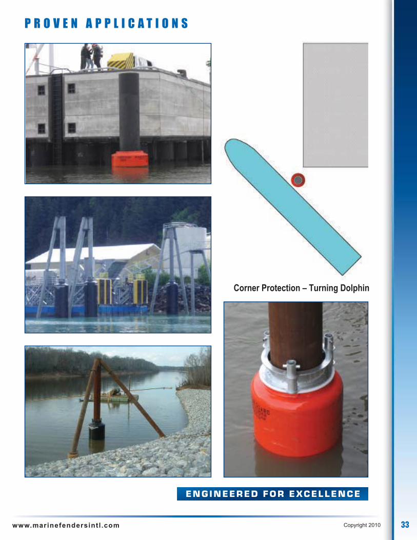
E N G I N E E R E D F O R E XC E L L E N C E
P R O V E N A P P L I C A T I O N S
Corner Protection – Turning Dolphin

34 www.marinefendersintl .com Copyright 2010
E N G I N E E R E D F O R E XC E L L E N C E
P R O V E N A P P L I C A T I O N S
Guiding Structures
35www.marinefendersintl .com Copyright 2010
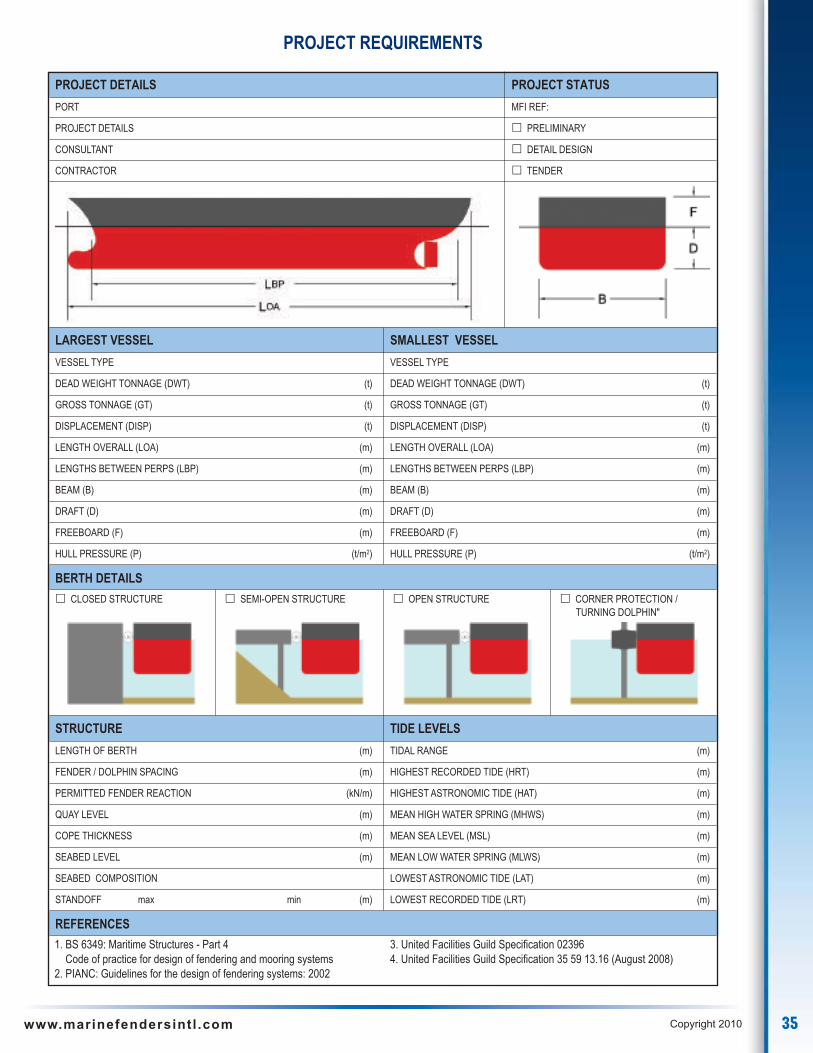
PROJECT REQUIREMENTS
PROJECT DETAILS PROJECT STATUS
PORT MFI REF:
PROJECT DETAILS � PRELIMINARY
CONSULTANT � DETAIL DESIGN
CONTRACTOR � TENDER
LARGEST VESSEL SMALLEST VESSEL
VESSEL TYPE VESSEL TYPE
DEAD WEIGHT TONNAGE (DWT) (t) DEAD WEIGHT TONNAGE (DWT) (t)
GROSS TONNAGE (GT) (t) GROSS TONNAGE (GT) (t)
DISPLACEMENT (DISP) (t) DISPLACEMENT (DISP) (t)
LENGTH OVERALL (LOA) (m) LENGTH OVERALL (LOA) (m)
LENGTHS BETWEEN PERPS (LBP) (m) LENGTHS BETWEEN PERPS (LBP) (m)
BEAM (B) (m) BEAM (B) (m)
DRAFT (D) (m) DRAFT (D) (m)
FREEBOARD (F) (m) FREEBOARD (F) (m)
HULL PRESSURE (P) (t/m2) HULL PRESSURE (P) (t/m2)
BERTH DETAILS
� CLOSED STRUCTURE � SEMI-OPEN STRUCTURE � OPEN STRUCTURE � CORNER PROTECTION /TURNING DOLPHIN"
STRUCTURE TIDE LEVELS
LENGTH OF BERTH (m) TIDAL RANGE (m)
FENDER / DOLPHIN SPACING (m) HIGHEST RECORDED TIDE (HRT) (m)
PERMITTED FENDER REACTION (kN/m) HIGHEST ASTRONOMIC TIDE (HAT) (m)
QUAY LEVEL (m) MEAN HIGH WATER SPRING (MHWS) (m)
COPE THICKNESS (m) MEAN SEA LEVEL (MSL) (m)
SEABED LEVEL (m) MEAN LOW WATER SPRING (MLWS) (m)
SEABED COMPOSITION LOWEST ASTRONOMIC TIDE (LAT) (m)
STANDOFF max min (m) LOWEST RECORDED TIDE (LRT) (m)
REFERENCES
1. BS 6349: Maritime Structures - Part 4 3. United Facilities Guild Specification 02396Code of practice for design of fendering and mooring systems 4. United Facilities Guild Specification 35 59 13.16 (August 2008)
2. PIANC: Guidelines for the design of fendering systems: 2002
36 www.marinefendersintl .com Copyright 2010
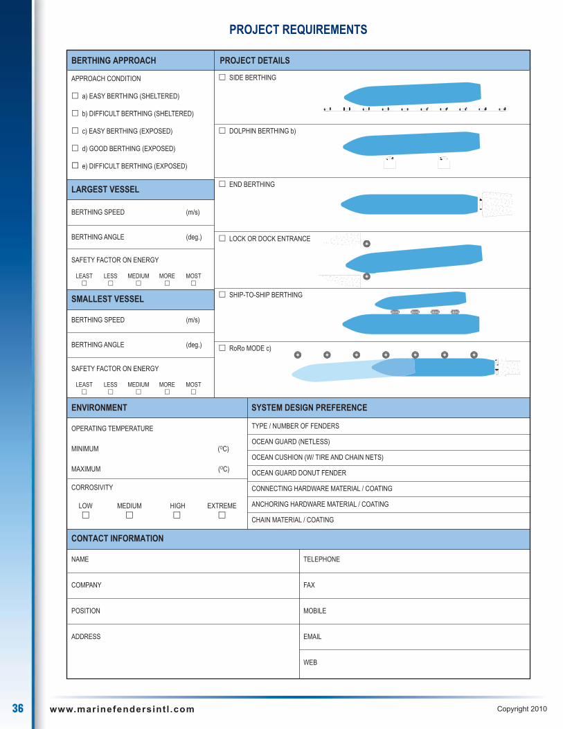
PROJECT REQUIREMENTS
BERTHING APPROACH PROJECT DETAILS
APPROACH CONDITION
� a) EASY BERTHING (SHELTERED)
� b) DIFFICULT BERTHING (SHELTERED)
� c) EASY BERTHING (EXPOSED)
� d) GOOD BERTHING (EXPOSED)
� e) DIFFICULT BERTHING (EXPOSED)
LARGEST VESSEL
BERTHING SPEED (m/s)
BERTHING ANGLE (deg.)
SAFETY FACTOR ON ENERGY
LEAST LESS MEDIUM MORE MOST � � � � �
SMALLEST VESSEL
BERTHING SPEED (m/s)
BERTHING ANGLE (deg.)
SAFETY FACTOR ON ENERGY
LEAST LESS MEDIUM MORE MOST � � � � �
ENVIRONMENT SYSTEM DESIGN PREFERENCE
OPERATING TEMPERATURE
MINIMUM (OC)
MAXIMUM (OC)
CORROSIVITY
LOW MEDIUM HIGH EXTREME� � � �
CONTACT INFORMATION
NAME TELEPHONE
COMPANY FAX
POSITION MOBILE
ADDRESS EMAIL
WEB
� SIDE BERTHING
� DOLPHIN BERTHING b)
� END BERTHING
� LOCK OR DOCK ENTRANCE
� SHIP-TO-SHIP BERTHING
� RoRo MODE c)
TYPE / NUMBER OF FENDERS
OCEAN GUARD (NETLESS)
OCEAN CUSHION (W/ TIRE AND CHAIN NETS)
OCEAN GUARD DONUT FENDER
CONNECTING HARDWARE MATERIAL / COATING
ANCHORING HARDWARE MATERIAL / COATING
CHAIN MATERIAL / COATING
OCEAN GUARDOCEAN GUARD
OCEAN GUARDOCEAN GUARD OCEAN GUARD OCEAN GUARDOCEAN GUARDOCEAN GUARD OCEAN GUARDOCEAN GUARD OCEAN GUARDOCEAN GUARD
OCE
AN G
UARD
OCE
AN G
UARD
OCEA
N G
UARD

37www.marinefendersintl .com Copyright 2010
The Ocean Guard™ Buoys resilient surfaces are constructed to withstand the toughest marine applications and environments the worldcan offer. The Ocean Guard™ Buoys constructed with the latest technology and materials exemplifies state-of-the-art technology in buoydesign and functionality. Marine Fenders International’s composite buoys are designed to absorb minor impacts without damaging thebuoy body or vessel.
OCEAN GUARD ™ Resilient Foam Filled Buoys
PERFORMANCE FEATURES
UNSINKABLE CONSTRUCTION
The Ocean Guard™ Buoys closed cell foam filled constructionprovides a buoy that is unsinkable even if its punctured.
IMPACT ABSORBING
The resilient outer foam layer and the reinforced elastomeric skin of theOcean Guard™ Buoys are designed to absorb impacts of vessels without damaging the buoy or the impacting vessel.
SUPERIOR TO STEEL BUOYS
The Ocean Guard™ Buoys are designed and constructed tobe lighter, more corrosion resistant, less maintenance, andeasier to handle than conventional steel buoys.The abrasionresistant urethane skin will resist the harshest environmentswithout corroding.
END FITTINGS
Ocean Guard™ Buoys end fittings are available in a variety of stylesincluding mooring tees, padeyes, quick release hooks, swivel eyes, bails,forged eyes, hawse pipe with capture plates, and navigational lights
CUSTOM DESIGNS
Maine Fenders International, Inc. engineers work closely withthe customer to select or custom design a Ocean Guard™Buoy to meet their specific requirements and needs.
NON MARKING
The tough, thick reinforced elastomeric urethane skin of Ocean Guard™Buoys is non marking and available in different colors and will not wear off.

38 www.marinefendersintl .com Copyright 2010
RIGID INNER CLOSED CELL URETHANE FOAM CORE
The second layer in Ocean Guard™ Buoys construction consistsof a US Coast Guard compliant rigid inner 100% closed cellurethane foam core. This strong foam core has excellentbuoyancy and compression strength properties. The foam ismolded directly onto the Internal Steel Central Strength Memberwhich provides an unsinkable buoy.
RESILIENT OUTER FOAM CORE
The third layer in Ocean Guard™ Buoys construction consists of aimpact absorbing closed cell cross-linked polyethylene foam corewhich is heat laminated into a one piece, solid foam core. Thesame heat lamination process used in our Ocean Guard™ fenders,produces a thermal bond between the layers of foam which isstronger than the foam itself which, will not delaminate even underthe most abusive berthing conditions. This impact absorbing foamcore is added to absorb vessel impacts without damaging the buoyor impacting the vessel.
REINFORCED ELASTOMERIC SKIN
The final layer, impact absorbing foam core is protected by a toughthick filament nylon tire cord reinforced elastomer skin. This non-marking reinforced elastomer fender skin is the wear surface of thefender. The reinforcing filaments are continuously wound in a helixpattern through up to 90 % of the elastomer skin and wrap aroundthe buoys end fittings. This continuous reinforcement of theelastomer skin not only increases the tensile and tear strength ofthe elastomer but also distributes loads through out the fender skin.
This tough resilient material is specially formulated to withstand theworlds harshest environmental conditions providing superiorperformance in extreme temperatures, toxic environments, againsthydrocarbons, salt water, ozone, and ultraviolet radiation.
CONSTRUCTION FEATURES
INTERNAL STEEL CENTRAL STRENGTH MEMBER
The Ocean Guard™ Buoys construction begins with a Ultra heavyduty internal steel central strength member which providesexcellent working load performance. The welded steel structurecontain load distribution plates which provide outstanding pullthrough performance.
• Ultra heavy duty central steal core load distribution construction
• Impact absorbing, resilientheat laminated cross-linkedpolyethylene foam core foam
• US Coast Guard approvedinner closed cell rigidurethane buoyancy foam
• Thick, tough filament nylon tire cordreinforced urethane skin
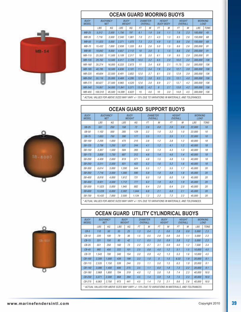
39www.marinefendersintl .com Copyright 2010
OCEAN GUARD MOORING BUOYSBUOY BUOYANCY BUOY DIAMETER HEIGHT HEIGHT WORKING
MODEL NET WEIGHT OVERALL BUOY BODY OVERALL LOAD
LBS KG LBS KG FT M FT M FT M LBS TONS
MB-25 5,512 2,500 1,756 797 6.1 1.9 3.6 1.1 7.6 2.3 100,000 45
MB-35 7,716 3,500 2,340 1,061 7.0 2.1 4.3 1.3 8.5 2.6 150,000 68
MB-50 11,023 5,000 2,371 1,075 7.5 2.3 4.9 1.5 8.6 2.6 150,000 68
MB-70 15,432 7,000 2,938 1,333 8.5 2.6 5.0 1.5 8.6 2.6 200,000 91
MB-90 19,842 9,000 4,657 2,112 10 3.0 5 1.5 8.6 2.6 200,000 91
MB-115 25,353 11,500 5,109 2,317 10 3.0 6.1 1.9 9.5 2.9 200,000 91
MB-135 29,762 13,500 6,017 2,729 10.5 3.2 6.5 2.0 10.0 3.0 300,000 136
MB-160 35,274 16,000 6,333 2,873 11 3.4 6.8 2.1 11.75 3.6 300,000 136
MB-185 40,785 18,500 6,836 3,101 11.1 3.4 7.8 2.4 12.7 3.9 300,000 136
MB-225 49,604 22,500 8,491 3,852 12.0 3.7 8.1 2.5 12.9 3.9 300,000 136
MB-250 55,116 25,000 9,469 4,295 12.5 3.8 8.3 2.5 13.1 4.0 300,000 136
MB-275 60,627 27,500 9,965 4,520 12.6 3.8 8.9 2.7 13.7 4.2 300,000 136
MB-340 74,957 34,000 11,841 5,371 13.83 4.2 9 2.7 13.8 4.2 300,000 136
MB-455 100,310 45,500 14,599 6,622 15 4.6 10 3.0 14.8 4.5 300,000 136
* ACTUAL VALUES FOR ABOVE SIZES MAY VARY +/- 15% DUE TO VARIATIONS IN MATERIALS, AND TOLERANCES.
OCEAN GUARD SUPPORT BUOYSBUOY BUOYANCY BUOY DIAMETER HEIGHT WORKING
MODEL NET WEIGHT OVERALL OVERALL LOAD
LBS KG LBS KG FT M FT M LBS TONS
SB-25 551 250 158 72 2.6 0.8 2.6 0.8 22,000 10
SB-50 1,102 500 285 129 3.2 1.0 3.2 1.0 22,000 10
SB-75 1,653 750 390 177 3.5 1.1 3.5 1.1 22,000 10
SB-100 2,205 1,000 475 215 3.8 1.2 3.8 1.2 40,000 18
SB-125 2,756 1,250 537 244 4.1 1.2 4.1 1.2 40,000 18
SB-150 3,307 1,500 584 265 4.3 1.3 4.3 1.3 40,000 18
SB-175 3,858 1,750 687 312 4.6 1.4 4.6 1.4 40,000 18
SB-200 4,409 2,000 819 371 4.8 1.5 4.8 1.5 40,000 18
SB-250 5,511 2,500 931 422 5.2 1.6 5.2 1.6 40,000 18
SB-300 6,614 3,000 1,200 544 5.5 1.7 5.5 1.7 45,000 20
SB-350 7,716 3,500 1,300 590 5.8 1.8 5.8 1.8 45,000 20
SB-400 8,818 4,000 1,612 731 6.0 1.8 6.0 1.8 45,000 20
SB-450 9,921 4,500 1,712 777 6.2 1.9 6.2 1.9 45,000 20
SB-500 11,023 5,000 1,945 882 6.4 2.0 6.4 2.0 45,000 20
SB-600 13,228 6,000 2,302 1,044 6.8 2.1 6.8 2.1 45,000 20
SB-700 15,432 7,000 2,500 1,134 7.2 2.2 7.2 2.2 45,000 20
* ACTUAL VALUES FOR ABOVE SIZES MAY VARY +/- 15% DUE TO VARIATIONS IN MATERIALS, AND TOLERANCES.
OCEAN GUARD UTILITY CYLINDRICAL BUOYSBUOY BUOYANCY BUOY DIAMETER BUOY HEIGHT WORKING
MODEL NET WEIGHT OVERALL HEIGHT OVERALL LOAD
LBS KG LBS KG FT M FT M FT M LBS TONS
CB-5 110 50 55 25 1.3 0.4 2 0.6 2.8 0.9 5,000 2.3
CB-10 220 100 79 36 1.5 0.5 2.8 0.8 3.6 1.1 5,000 2.3
CB-15 331 150 93 42 1.7 0.5 3.0 0.9 3.8 1.2 5,000 2.3
CB-25 551 250 160 73 2.2 0.7 3.1 0.9 4.0 1.2 7,500 3.4
CB-45 992 450 222 101 2.5 0.8 4.0 1.2 5.1 1.5 10,000 4.5
CB-70 1,543 700 340 154 3.0 0.9 4.2 1.3 5.3 1.6 10,000 4.5
CB-100 2,205 1,000 439 199 3.3 1.0 5 1.5 6.33 1.9 20,000 9.1
CB-115 2,535 1,150 539 244 3.5 1.1 5.0 1.5 6.3 1.9 20,000 9.1
CB-140 3,086 1,400 606 275 3.5 1.1 6.0 1.8 7.3 2.2 20,000 9.1
CB-180 3,968 1,800 704 319 4.0 1.2 5.8 1.8 7.4 2.3 40,000 18.0
CB-230 5,071 2,300 868 394 4.5 1.4 5.9 1.8 7.5 2.3 40,000 18.0
CB-275 6,063 2,750 973 441 4.5 1.4 7.0 2.1 8.6 2.6 40,000 18.0
* ACTUAL VALUES FOR ABOVE SIZES MAY VARY +/- 15% DUE TO VARIATIONS IN MATERIALS, AND TOLERANCES.

40 www.marinefendersintl .com Copyright 2010
OCEAN GUARD PENDANT BUOYSBUOY BUOYANCY BUOY DIAMETER BUOY HEIGHT WORKING
MODEL NET WEIGHT OVERALL LENGTH OVERALL LOAD
LBS KG LBS KG FT M FT M FT M LBS TONS
PB-25 5,511 2,500 1,223 555 4.5 1.4 6.8 2.1 7.3 2.2 150,000 68
PB-50 11,023 5,000 2,123 963 6.0 1.8 7.2 2.2 8.7 2.7 150,000 68
PB-75 16,534 7,500 3,184 1,444 6.5 2.0 9.2 2.8 9.2 2.8 150,000 68
PB-100 22,046 10,000 2,735 1,241 6.5 2.0 11.0 3.4 9.3 2.8 150,000 68
PB-150 33,069 15,000 4,020 1,823 8.0 2.4 11.5 3.5 10.9 3.3 150,000 68
PB-200 44,092 20,000 4,922 2,233 8.5 2.6 13.5 4.1 11.5 3.5 200,000 91
PB-250 55,115 25,000 5,827 2,643 9.0 2.7 15.0 4.6 11.8 3.6 200,000 91
PB-300 66,138 30,000 6,688 3,034 9.5 2.9 16.0 4.9 12.8 3.9 200,000 91
PB-350 77,160 35,000 10,581 4,800 10.3 3.1 16.8 5.1 14.5 4.4 250,000 114
PB-400 88,183 40,000 11,449 5,193 10.5 3.2 18.0 5.5 16.3 5.0 250,000 114
* ACTUAL VALUES FOR ABOVE SIZES MAY VARY +/- 15% DUE TO VARIATIONS IN MATERIALS, AND TOLERANCES.
OCEAN GUARD MODULAR ANCHOR PENDANT BUOYSBUOY BUOYANCY NUMBER DIAMETER THROUGH
MODEL NET OF MODULES OVERALL PIPE DIAMETER
LBS KG FT M IN MM
MAPB2-4 8,818 4,000 2 6.6 2.0 6.0 152
MAPB4-8 17,637 8,000 4 6.6 2.0 6.0 152
MAPB2-8 17,637 8,000 2 7.5 2.3 6.0 152
MAPB4-16 35,273 16,000 4 7.5 2.3 6.0 152
MAPB2-11 24,250 11,000 2 9.8 3.0 8.0 203
MAPB4-22 48,501 22,000 4 9.8 3.0 8.0 203
MAPB2-17 37,478 17,000 2 10.5 3.2 10.0 254
MAPB4-34 74,956 34,000 4 10.5 3.2 10.0 254
MAPB2-23 50,705 23,000 2 10.5 3.2 10.0 254
MAPB4-46 101,411 46,000 4 10.5 3.2 10.0 254
* ACTUAL VALUES FOR ABOVE SIZES MAY VARY +/- 15% DUE TO VARIATIONS IN MATERIALS, AND TOLERANCES.
OCEAN GUARD NAVIGATIONAL AND MARKER BUOYSBUOY BUOYANCY BUOY BUOY BUOY BODY
MODEL NET WEIGHT DIAMETER HEIGHT
LBS KG LBS KG FT M FT M
NAV-100 221 100 194 88 3.0 0.9 2.3 0.7
NAV-200 441 200 399 181 3.8 1.2 3.0 0.9
NAV-500 1,103 500 650 295 4.9 1.5 3.0 0.9
NAV-750 1,654 750 981 445 6.7 2.0 3.3 1.0
NAV-1000 2,205 1,000 1,816 824 8.5 2.6 4.2 1.3
NAV-3000 6,615 3,000 3,112 1,412 10.0 3.0 4.5 1.4
NAV-5000 11,025 5,000 4,462 2,024 10.2 3.1 6.0 1.8
NAV-7500 16,538 7,500 6,703 3,040 11.8 3.6 6.6 2.0
NAV-10000 22,050 10,000 7,845 3,558 13.2 4.0 6.0 1.8
* ACTUAL VALUES FOR ABOVE SIZES MAY VARY +/- 15% DUE TO VARIATIONS IN MATERIALS, AND TOLERANCES.
OCEAN GUARD OCEANOGRAPHIC BUOYSBUOY BUOYANCY FLOTATION TOTAL DIAMETER DIAMETER FLOTATION TOWER
MODEL NET WEIGHT WEIGHT OVERALL INTERNAL HEIGHT HEIGHT
LBS KG LBS KG LBS KG FT M FT M FT M FT M
OG-10 2,205 1,000 60 27 513 233 5.4 1.6 2.2 0.7 2.3 0.7 5.6 1.7
OG-15 3,307 1,500 72 33 606 275 6.1 1.9 2.3 0.7 2.4 0.7 5.6 1.7
OG-20 4,409 2,000 99 45 752 341 6.5 2.0 2.5 0.8 2.6 0.8 6.1 1.9
ATLAS-3 5,000 2,268 130 59 1,200 544 7.4 2.3 3.2 1.0 3.2 1.0 7.0 2.1
* ACTUAL VALUES FOR ABOVE SIZES MAY VARY +/- 15% DUE TO VARIATIONS IN MATERIALS, AND TOLERANCES.

41www.marinefendersintl .com Copyright 2010
OCEAN GUARD UNIVERSAL BUOYSBUOY NET BUOYANCY (MIN) BUOY WEIGHT BODY DIAMETER BODY HEIGHT OVERALL HEIGHT
MODEL LBS KG LBS KG FT M FT M FT M
UB-1500 1,500 680 710 322 4.2 1.3 2.5 0.8 4.3 1.3
UB-2000 2,000 907 801 363 4.2 1.3 3.3 1.0 5.5 1.7
UB-2500 2,500 1,134 689 313 5.0 1.5 2.9 0.9 5.0 1.5
UB-3000 3,000 1,361 929 421 5.0 1.5 3.3 1.0 5.5 1.7
UB-4000 4,000 1,814 1,488 675 6.0 1.8 3.3 1.0 5.5 1.7
UB-5000 5,000 2,268 1,570 712 6.0 1.8 3.8 1.1 6.0 1.8
* ACTUAL VALUES FOR ABOVE SIZES MAY VARY +/- 15% DUE TO VARIATIONS IN MATERIALS, AND TOLERANCES.
OCEAN GUARD CHAIN THROUGH BUOYSBUOY NET BUOY BODY BODY OVERALL THROUGH
MODEL BUOYANCY WEIGHT DIAMETER LENGTH LENGTH PIPE DIAMETER
LB KG LB KG FT M FT M FT M IN MM
CTB-100 2,205 1000 1,170 570 3.6 1.1 5.8 1.7 7.0 2.1 13.0 330
CTB-150 3,307 1,500 1,345 610 4.1 1.3 5.9 1.7 7.1 2.1 13.0 330
CTB-200 4,409 2,000 1,488 675 4.5 1.4 6.2 1.9 7.7 2.4 13.0 330
CTB-225 4,960 2,250 1,842 777 4.9 1.5 6.0 2.0 7.5 2.4 15.0 381
CTB-275 6,063 2,750 2,023 840 5.1 1.6 6.6 2.1 8.0 2.6 15.0 381
CTB-350 7,716 3,500 2,698 1,060 5.1 1.6 8.6 2.9 10.0 3.4 17.0 432
CTB-400 8,818 4,000 2,791 1,159 5.3 1.7 9.0 2.6 10.3 3.1 17.0 432
CTB-450 9,921 4,500 3,076 1,395 5.5 1.8 9.2 2.6 10.5 3.1 19.0 483
CTB-550 12,125 5,500 3,440 1,560 5.8 1.8 9.8 3.2 11.0 3.7 19.0 483
* ACTUAL VALUES FOR ABOVE SIZES MAY VARY +/- 15% DUE TO VARIATIONS IN MATERIALS, AND TOLERANCES.
OCEAN GUARD RECTANGULAR ANCHOR PENDANT BUOYSBUOY BUOYANCY BUOY BUOY DIMENSIONS WORKING
MODEL NET WEIGHT LENGTH HEIGHT WIDTH OVERALL HEIGHT LOAD
LBS KG LBS KG FT M FT M FT M FT M FT TONS
RPB-10 2,200 1000 408 185 3.0 0.9 5.0 1.5 3.0 0.9 7.3 2.2 150,000 68
RPB-20 4,400 2000 817 371 3.6 1.1 5.0 1.5 5.0 1.5 7.3 2.2 150,000 68
RPB-40 8,800 4000 1,470 667 4.5 1.4 6.0 1.8 6.0 1.8 9.9 3.0 150,000 68
RPB-60 13,200 6000 3,060 1,388 5.0 1.5 7.0 2.1 8.5 2.6 10.9 3.3 150,000 68
RPB-80 17,600 8000 3,514 1,594 5.4 1.6 7.5 2.3 8.5 2.6 11.4 3.5 150,000 68
RPB-100 22,000 10000 4,312 1,956 6.0 1.8 9.0 2.7 8.1 2.5 12.6 3.8 150,000 68
RPB-120 26,400 12000 4,641 2,105 6.5 2.0 9.5 2.9 8.4 2.6 13.4 4.1 150,000 68
RPB-140 30,800 14000 5,835 2,647 6.5 2.0 10.5 3.2 9.0 2.7 14.8 4.5 200,000 91
RPB-160 35,200 16000 6,442 2,922 6.5 2.0 10.5 3.2 10.5 3.2 14.6 4.5 200,000 91
RPB-180 39,600 18000 7,195 3,264 6.5 2.0 11.5 3.5 11.0 3.4 15.6 4.8 200,000 91
RPB-200 44,000 20000 7,533 3,417 8.0 2.4 11.0 3.4 10.7 3.3 14.8 4.5 200,000 91
RPB-250 55,000 25000 8,427 3,822 8.5 2.6 12.6 3.8 10.8 3.3 16.5 5.0 200,000 91
RPB-300 66,000 30000 9,918 4,499 8.5 2.6 14.4 4.4 11.1 3.4 18.2 5.5 200,000 91
* ACTUAL VALUES FOR ABOVE SIZES MAY VARY +/- 15% DUE TO VARIATIONS IN MATERIALS, AND TOLERANCES.
Bail eye Pad Eye Pick-up Tee Swivel Eye
Universal Buoy End Fittings

42 www.marinefendersintl .com Copyright 2010
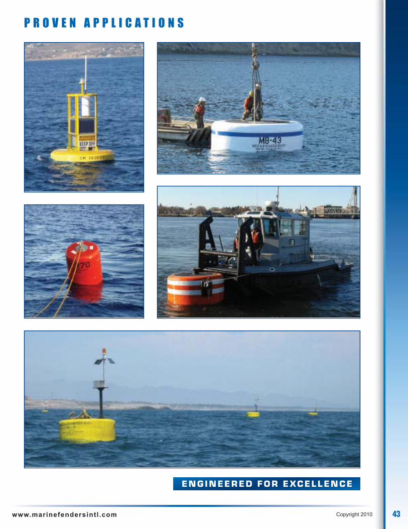
E N G I N E E R E D F O R E XC E L L E N C E
P R O V E N A P P L I C A T I O N S
43www.marinefendersintl .com Copyright 2010
E N G I N E E R E D F O R E XC E L L E N C E
P R O V E N A P P L I C A T I O N S
44 www.marinefendersintl .com Copyright 2010
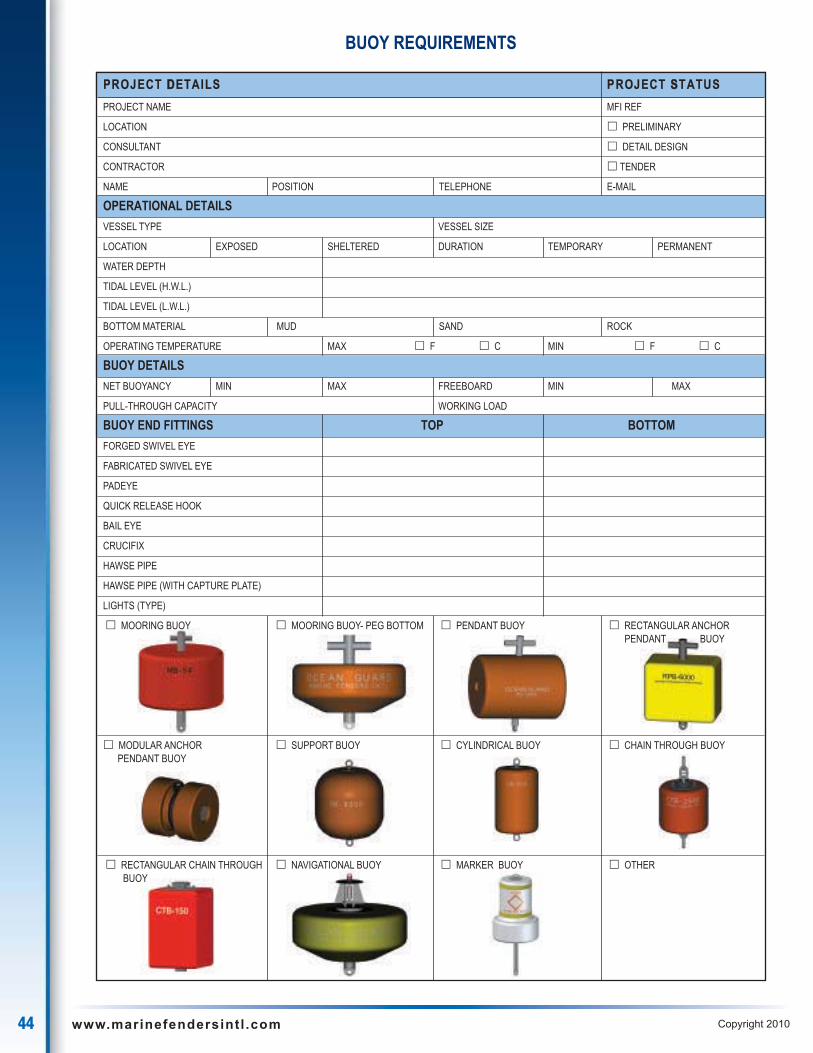
BUOY REQUIREMENTS
PROJECT DDETAILS PROJECT SSTATUS
PROJECT NAME MFI REF
LOCATION � PRELIMINARY
CONSULTANT � DETAIL DESIGN
CONTRACTOR � TENDER
NAME POSITION TELEPHONE E-MAIL
OPERATIONAL DETAILS
VESSEL TYPE VESSEL SIZE
LOCATION EXPOSED SHELTERED DURATION TEMPORARY PERMANENT
WATER DEPTH
TIDAL LEVEL (H.W.L.)
TIDAL LEVEL (L.W.L.)
BOTTOM MATERIAL MUD SAND ROCK
OPERATING TEMPERATURE MAX � F � C MIN � F � C
BUOY DETAILS
NET BUOYANCY MIN MAX FREEBOARD MIN MAX
PULL-THROUGH CAPACITY WORKING LOAD
BUOY END FITTINGS TOP BOTTOM
FORGED SWIVEL EYE
FABRICATED SWIVEL EYE
PADEYE
QUICK RELEASE HOOK
BAIL EYE
CRUCIFIX
HAWSE PIPE
HAWSE PIPE (WITH CAPTURE PLATE)
LIGHTS (TYPE)
� MOORING BUOY � MOORING BUOY- PEG BOTTOM � PENDANT BUOY � RECTANGULAR ANCHORPENDANT BUOY
� MODULAR ANCHOR � SUPPORT BUOY � CYLINDRICAL BUOY � CHAIN THROUGH BUOYPENDANT BUOY
� RECTANGULAR CHAIN THROUGH � NAVIGATIONAL BUOY � MARKER BUOY � OTHER BUOY
45www.marinefendersintl .com Copyright 2010
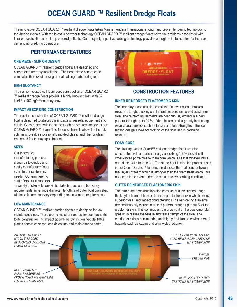
The innovative OCEAN GUARD ™ resilient dredge floats takes Marine Fenders International’s tough and proven fendering technology tothe dredge market. With the latest in polymer technology OCEAN GUARD ™ resilient dredge floats solve the problems associated withfiber or plastic slip-on or clamp on dredge floats. Our buoyant, impact absorbing technology provides a tough reliable solution for the mostdemanding dredging operations.
OCEAN GUARD ™ Resilient Dredge Floats
PERFORMANCE FEATURES
ONE PIECE - SLIP ON DESIGN
OCEAN GUARD ™ resilient dredge floats are designed andconstructed for easy installation. Their one piece constructioneliminates the risk of loosing or maintaining parts during use.
HIGH BUOYANCY
The resilient closed cell foam core construction of OCEAN GUARD™ resilient dredge floats provide a highly buoyant float, with 59lbs/ft3 or 950 kg/m3 net buoyancy.
IMPACT ABSORBING CONSTRUCTION
The resilient construction of OCEAN GUARD ™ resilient dredgefloat is designed to absorb the impacts of vessels, equipment anddebris. Constructed with the same tough proven technology as ourOCEAN GUARD ™ foam filled fenders, these floats will not crack,splinter or break as rotationally molded plastic and fiber or glassreinforced floats may upon impacts.
SIZES
Our innovativemanufacturing processallows us to quickly andeasily manufacture floatssized to our customersneeds. Our engineeringstaff offers our customersa variety of size solutions which take into account, buoyancyrequirements, inner pipe diameter, length, and outer float diameter.All these factors can vary depending on customers requirements.
LOW MAINTENANCE
OCEAN GUARD ™ resilient dredge floats are designed for lowmaintenance use. There are no metal or non resilient componentsto its construction. Its impact absorbing low friction flexible 100%plastic construction reduces downtime and maintenance costs.
CONSTRUCTION FEATURES
INNER REINFORCED ELASTOMERIC SKIN
The inner layer construction consists of a low friction, abrasionresistant, tough, thick nylon filament tire cord reinforced elastomerskin. The reinforcing filaments are continuously wound in a helixpattern through up to 90 % of the elastomer skin greatly increasingwear characteristics such as tensile and tear strengths. The lowfriction design allows for rotation of the float and is corrosionresistant
FOAM CORE
The floating Ocean Guard™ resilient dredge floats are alsoconstructed with a resilient energy absorbing 100% closed cellcross-linked polyethylene foam core which is heat laminated into aone piece, solid foam core. The same heat lamination process usedin our Ocean Guard™ fenders, produces a thermal bond betweenthe layers of foam which is stronger than the foam itself which, willnot delaminate even under the most abusive berthing conditions.
OUTER REINFORCED ELASTOMERIC SKIN
The outer layer construction also consists of a low friction, tough,thick nylon filament tire cord reinforced elastomer skin which offerssuperior wear and impact characteristics The reinforcing filamentsare continuously wound in a helix pattern through up to 90 % of theelastomer skin .This continuous reinforcement of the elastomer skingreatly increases the tensile and tear strength of the skin. Theelastomer skin is non-marking and highly resistant to environmentalhazards such as ozone and ultra-violet radiation.
INTERNAL FILAMENTNYLON TIRE CORDREINFORCED URETHANEELASTOMER SKIN
OUTER FILAMENT NYLON TIRECORD REINFORCED URETHANE
ELASTOMER SKIN
HEAT LAMINATED IMPACT ABSORBINGCROSSLINKED POLYETHYLENE FLOTATION FOAM CORE
HIGH VISIBILITY OUTERURETHANE ELASTOMER SKIN
TYPICALDREDGE PIPE

46 www.marinefendersintl .com Copyright 2010
OCEAN GUARD floating Port Security Barriers systems are designed to provide the highest level of security and quality for Port facilities.This highly visible floating physical barrier is designed for easy installation and maintenance. OCEAN GUARD floating Port SecurityBarriers systems are modular and available in a number of sizes. Smaller sizes are designed as demarcation barriers. The larger sizesare designed not only as demarcation barriers but also to physically restrict entry in sensitive areas.
OCEAN GUARD ™ Port Security Barriers Systems
PERFORMANCE FEATURES
• Physical deterrent
• Highly visible
• Low maintenance and long life construction
• Foam filled construction (will not fail if punctured)
• High tensile designs
• Modular design allows easy resizing and transportation
Barrier Buoys
PSB barrier modules
Anchors
OCEAN GUARD – PSB floating Port Security Barriers systemsare available with 2 different internal strength member designs.
• Ultra heavy duty integral swivel end fittings which are internallyconnected with a stud link chain. Each end fitting is undertension and swivels independently.
• Alternatively central hawse pipe with end flanges. A chain ispassed through the central pipe core and locked in place with aheavy duty locking plate.
OCEAN GUARD Barrier Buoys are specially designed tomaintain the Port Security Barrier System in located in theirdesignated locations. The substantial internal central strengthmember is design to moor barrier sections and absorb impactloads from the barrier system.
CONSTRUCTION FEATURES
• Impact absorbing heat laminated cross linked polyethylenefoam core.
• Tough, thick filament nylon tire cord reinforced urethaneskin – highly visible orange. Other colors available.
• Heavy duty integral steel strength members
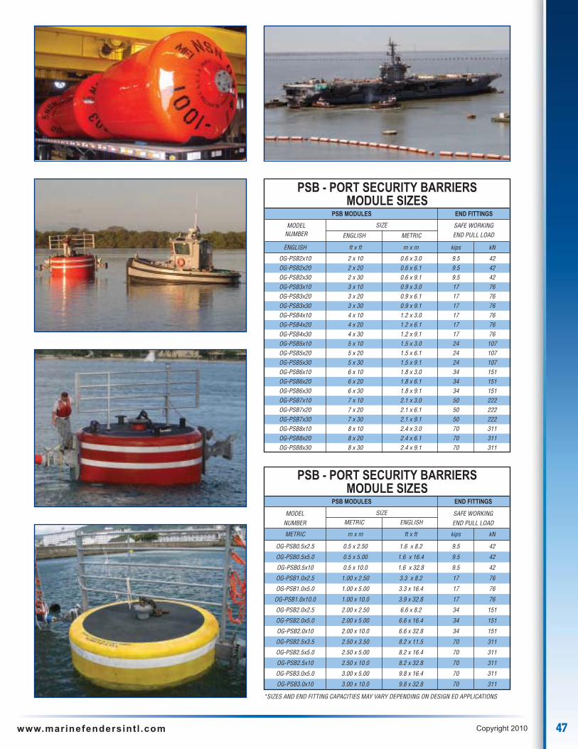
47www.marinefendersintl .com Copyright 2010
PSB - PORT SECURITY BARRIERSMODULE SIZES
PSB MODULES END FITTINGS
SIZE METRIC ENGLISH
METRIC m x m ft x ft kips kN
OG-PSB0.5x2.5 0.5 x 2.50 1.6 x 8.2 9.5 42
OG-PSB0.5x5.0 0.5 x 5.00 1.6 x 16.4 9.5 42
OG-PSB0.5x10 0.5 x 10.0 1.6 x 32.8 9.5 42
OG-PSB1.0x2.5 1.00 x 2.50 3.3 x 8.2 17 76
OG-PSB1.0x5.0 1.00 x 5.00 3.3 x 16.4 17 76
OG-PSB1.0x10.0 1.00 x 10.0 3.9 x 32.8 17 76
OG-PSB2.0x2.5 2.00 x 2.50 6.6 x 8.2 34 151
OG-PSB2.0x5.0 2.00 x 5.00 6.6 x 16.4 34 151
OG-PSB2.0x10 2.00 x 10.0 6.6 x 32.8 34 151
OG-PSB2.5x3.5 2.50 x 3.50 8.2 x 11.5 70 311
OG-PSB2.5x5.0 2.50 x 5.00 8.2 x 16.4 70 311
OG-PSB2.5x10 2.50 x 10.0 8.2 x 32.8 70 311
OG-PSB3.0x5.0 3.00 x 5.00 9.8 x 16.4 70 311
OG-PSB3.0x10 3.00 x 10.0 9.8 x 32.8 70 311
MODELNUMBER
SAFE WORKINGEND PULL LOAD
*SIZES AND END FITTING CAPACITIES MAY VARY DEPENDING ON DESIGN ED APPLICATIONS
PSB - PORT SECURITY BARRIERSMODULE SIZES
PSB MODULES END FITTINGS
SIZE
ENGLISH METRIC
ENGLISH ft x ft m x m kips kN
OG-PSB2x10 2 x 10 0.6 x 3.0 9.5 42OG-PSB2x20 2 x 20 0.6 x 6.1 9.5 42OG-PSB2x30 2 x 30 0.6 x 9.1 9.5 42OG-PSB3x10 3 x 10 0.9 x 3.0 17 76OG-PSB3x20 3 x 20 0.9 x 6.1 17 76OG-PSB3x30 3 x 30 0.9 x 9.1 17 76OG-PSB4x10 4 x 10 1.2 x 3.0 17 76OG-PSB4x20 4 x 20 1.2 x 6.1 17 76OG-PSB4x30 4 x 30 1.2 x 9.1 17 76OG-PSB5x10 5 x 10 1.5 x 3.0 24 107OG-PSB5x20 5 x 20 1.5 x 6.1 24 107OG-PSB5x30 5 x 30 1.5 x 9.1 24 107OG-PSB6x10 6 x 10 1.8 x 3.0 34 151OG-PSB6x20 6 x 20 1.8 x 6.1 34 151OG-PSB6x30 6 x 30 1.8 x 9.1 34 151OG-PSB7x10 7 x 10 2.1 x 3.0 50 222OG-PSB7x20 7 x 20 2.1 x 6.1 50 222OG-PSB7x30 7 x 30 2.1 x 9.1 50 222OG-PSB8x10 8 x 10 2.4 x 3.0 70 311OG-PSB8x20 8 x 20 2.4 x 6.1 70 311OG-PSB8x30 8 x 30 2.4 x 9.1 70 311
MODELNUMBER
SAFE WORKINGEND PULL LOAD

48 www.marinefendersintl .com Copyright 2010
As a leader in urethane polymer technology Marine Fenders International has developed the appropriate materials and processes toprovide superior protection and encapsulation of steel and timber pilings. Our OCEAN GUARD™ piling coatings can be applied as aencapsulate to creosote treated piling, preventing leashing of toxins into waterways. Additionally when applied to steel pilings, this resilientprotective coating will not chip or crack like brittle epoxy pile coatings.
STEEL PILINGS
OCEAN GUARD™ piling coatings provide aresilient flexible alternative to the brittle epoxypile coatings. Unlike epoxy paints and coatingsthis impact resistant coating will not crack ifdeflected or impacted . OCEAN GUARD™piling coatings provides a innovative lowmaintenance, corrosion resistant solution steelpile coatings.
TIMBER PILINGS
OCEAN GUARD™ piling coatings providean environmentally safe alternative totraditional chemically-treated wooden pilesand can be applied to both untreated andtreated wooden piles. The thick toughelastomeric coating penetrates and coatscracks, checks, and all surfaces. Thisencapsulation treatment keeps helpsprevent the micro organisms from attackingand deteriorating the wooden piles.
OCEAN CAMEL™
The OCEAN CAMEL™ marine timber camel extends the life of a traditional timbercamel. As Ports looking for environmentally safe solutions for chemically treatedcamels, OCEAN CAMEL™ marine timber camel coatings provide tough
encapsulation and protection of these untreated and treatedwooden camels. These camels are used to distribute vesselberthing loads across multiple fendering pings and alsoprovide standoff of the vessel from the pier.
OCEAN GUARD™ Coated Piles
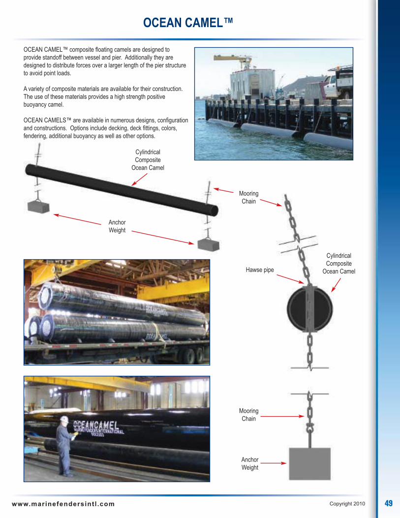
49www.marinefendersintl .com Copyright 2010
OCEAN CAMEL™ composite floating camels are designed toprovide standoff between vessel and pier. Additionally they aredesigned to distribute forces over a larger length of the pier structureto avoid point loads.
A variety of composite materials are available for their construction.The use of these materials provides a high strength positivebuoyancy camel.
OCEAN CAMELS™ are available in numerous designs, configurationand constructions. Options include decking, deck fittings, colors,fendering, additional buoyancy as well as other options.
OCEAN CAMEL™
Cylindrical Composite
Ocean Camel
Cylindrical Composite
Ocean Camel
AnchorWeight
AnchorWeight
MooringChain
MooringChain
Hawse pipe

50 www.marinefendersintl .com Copyright 2010
OCEAN CAMEL™
Non-slip decking
Extremely low maintenanceOceanTimber construction
Extremely low maintenanceOceanTimber construction
Additional buoyancyIf required
Additional buoyancyIf required
Non-slip decking
Hawse pipe

51www.marinefendersintl .com Copyright 2010
Fendering And Mooring Hardware
In any fendering or mooring system all components play a integral part in the durability and success of the system. All the basic componentsin the system must be appropriately matched in design function and strength to achieve the systems maximum performance and safety.
Marine Fenders International, Inc. offers a large variety of fendering and mooring marine hardware to ensure the performance of the designedfendering or mooring system. Our large selection of Anchors, Chains, Quick Release Hooks, Shackles, Swivels, Tow Plates are available forimmediate delivery. Available in a variety of grades, carbon steel or stainless steel with ABS Certificates.
DOCK PLATES – PAD EYES SYSTEMS
• Fender mounting pad eye are designed and constructed to meetthe performance requirements of a fendering system design
• 316 stainless steel embeds
• Epoxy Grout
CHAIN
• Dock Chain
• Long Link Chain
• Stud-Link Chain
• Available in Grade 1, Grade 2and Grade 3
• All chain is available in bothBlack and Galvanized.
QUICK RELEASE HOOKS(BUOY TYPE)
• Available in proof test of300,000 and 400,000 lbs
• Total Weight 375 lbs
SHACKLES
• Bolt Type Anchor Shackles
• Bolt Type Chain Shackles
• Screw Pin Anchor Shackles
• Screw Pin Chain Shackles
• Towing Shackles – High Capacity
• Shackles available in both Hot-Dipped
• Galvanized and Stainless Steel
SWIVELS
• Eye and Eye Swivels
• Jaw and Eye Swivels
TOW PLATES
• Available in 3 sizes • Three connection points• Accepts hardware from
1-1/2 inch to 4 inches
ANCHORS
• Stockless Anchors available from 200 lbs to 50,000 lb anchor weight• Workboat Anchors available from 20 lbs to 30,000 lb anchor weight
PRESENTED BY:
Related Documents