1 S.A. C-24 Manual Marine diesel engines Operator’s manual MINI-17 MINI-29 MINI-33 MINI-44 MINI-55 U_MIB3_EN Revision 2

Welcome message from author
This document is posted to help you gain knowledge. Please leave a comment to let me know what you think about it! Share it to your friends and learn new things together.
Transcript
1
Solé Diesel, S.A. C-243 b, km 2 · 08760 Martorell (Barcelona) ·Tel. +34 93 775 14 00 · www.solediesel.com · [email protected]
Manual del Operador Motores Diésel Marino. Revisión 0.07/2018
Marine diesel engines Operator’s manual
MINI-17
MINI-29
MINI-33
MINI-44
MINI-55
U_MIB3_EN
Revision 2


Solé, S.A. C-243 b, km 2 · 08760 Martorell (Barcelona) ·Tel. +34 93 775 14 00 · www.solediesel.com · [email protected] 3 Marine diesel engines. Operator’s manual
Introduction
Introduction
Presentation Dear Customer,
First of all, we would like to thank you for choosing a Solé Diesel product. We recommend that
you read this manual carefully before carrying out any of the operations and keep it close at hand,
near the engine, as it can be of great use in the future.
Our goal as a manufacturing company is that you enjoy our product, regardless of the use you
make of it. The equipment manufactured in Solé Diesel facilities is designed to offer the highest
performance in the most demanding operating conditions.
The images, text and information contained in this manual are based on the product’s
features at the time of publication. Solé Diesel reserves the right to modify this document without prior
notice.
Solé, S.A. C-243 b, km 2 · 08760 Martorell (Barcelona) ·Tel. +34 93 775 14 00 · www.solediesel.com · [email protected] 4 Marine diesel engines. Operator’s manual
Table of contents Table of contents
Introduction ………………………………………………………………………………………………………………………………..3
Safety precautions and instructions ..................................................................................................... 6
Solé Diesel warranty ........................................................................................................................... 10
Section 1 – Engine information .......................................................................................................... 13
1.1. Engine Identification ............................................................................................................... 13 1.2. Engine parts identification...................................................................................................... 14
Section 2 – Transport, handling and storage ..................................................................................... 15
2.1. Reception ................................................................................................................................ 15 2.2. Transport and handling the packed engine .......................................................................... 15 2.3. Transporting and handling the unpacked Engine ................................................................. 16 2.4. Storage of packed and unpacked engine .............................................................................. 16
Section 3 - Installation ........................................................................................................................ 17
3.1. Angle of installation ................................................................................................................ 17 3.2. Engine Installation .................................................................................................................. 17
Section 4 - Operation .......................................................................................................................... 18
4.1. Prestart checklist .................................................................................................................... 18 4.2. Cranking the engine ................................................................................................................ 18 4.3. Stopping engine ...................................................................................................................... 19 4.4. Engine operation at low temperatures .................................................................................. 19 4.5. Winterization and preservation .............................................................................................. 20 4.6. Maintenance during the storage ............................................................................................ 21 4.7. Restoration of operational conditions ................................................................................... 21
Section 5 – Systems and scheduled maintenance ............................................................................ 22
5.1. Safety and prevention ............................................................................................................. 22 5.2. Periodic maintenance schedule ............................................................................................. 22 5.3. General .................................................................................................................................... 24
Maintenance task. Screw tightening, fastening ................................................................................................................... 24 Maintenance task. Valve clearance inspection .................................................................................................................... 24 Maintenance task. Compression pressure inspection ......................................................................................................... 25
5.4. Lubrication system .................................................................................................................. 26 Circuit description .................................................................................................................................................................. 26 Oil specifications .................................................................................................................................................................... 26 Maintenance task. Oil filter change ...................................................................................................................................... 26 Maintenance task. Oil level check ........................................................................................................................................ 27 Maintenance task. Oil fill/Change......................................................................................................................................... 28
5.5. Fuel system ............................................................................................................................. 28 Circuit description .................................................................................................................................................................. 28 Fuel specifications ................................................................................................................................................................. 28 Maintenance task. Fuel level inspection .............................................................................................................................. 29 Maintenance task. Fuel tank clean ....................................................................................................................................... 29 Maintenance task. Water separator filter purge .................................................................................................................. 29 Maintenance task. Fuel filter change ................................................................................................................................... 29 Maintenance task. Injection pump inspection ..................................................................................................................... 29 Maintenance task. Injector inspection .................................................................................................................................. 30 Maintenance task. Bleeding air from the fuel system ......................................................................................................... 31
Solé, S.A. C-243 b, km 2 · 08760 Martorell (Barcelona) ·Tel. +34 93 775 14 00 · www.solediesel.com · [email protected] 5 Marine diesel engines. Operator’s manual
Table of contents 5.6. Cooling system ........................................................................................................................ 31
Coolant specifications............................................................................................................................................................ 32 Maintenance task. Coolant check ......................................................................................................................................... 32 Maintenance task. Coolant fill/change ................................................................................................................................. 32 Maintenance task. Seawater filter inspection ...................................................................................................................... 32 Maintenance task. Seawater pump impeller inspection ..................................................................................................... 33 Maintenance task. Zinc anode inspection ............................................................................................................................ 33
5.7. Inlet and exhaust system........................................................................................................ 34 Exhaust circuit description .................................................................................................................................................... 34 Maintenance task. Air filter inspection ................................................................................................................................. 35 Maintenance task. Exhaust gas, noise and vibrations inspection ...................................................................................... 35
5.8. Electrical system ..................................................................................................................... 36 Control Panel .......................................................................................................................................................................... 36 Battery .................................................................................................................................................................................... 36 Circuit protection .................................................................................................................................................................... 36 Relays ..................................................................................................................................................................................... 36 Maintenance task. Incandescent glow plug inspection ....................................................................................................... 37 Maintenance task. Starter motor inspection ........................................................................................................................ 37 Maintenance task. Alternator belt tension inspection ......................................................................................................... 37 Maintenance task. Battery level ............................................................................................................................................ 38
Section 6 - Troubleshooting ................................................................................................................ 39
Section 7 - Technical specifications ................................................................................................... 44
Section 8 – Tightening torques .......................................................................................................... 48
Section 9 – Wiring diagrams .............................................................................................................. 50
Section 10 – Overall dimensions ....................................................................................................... 53
Section 11 – Instructions to Replace and Remove ............................................................................ 59
Section 12 - Inspection prior to the delivery of propulsion engines ................................................... 61
Section 13 – Declaration of conformity for recreational Craft Propulsion Engines ............................ 63
Maintenance log ................................................................................................................................. 68
Solé, S.A. C-243 b, km 2 · 08760 Martorell (Barcelona) ·Tel. +34 93 775 14 00 · www.solediesel.com · [email protected] 6 Marine diesel engines. Operator’s manual
Safety precautions and
instructions Safety precautions and instructions
Solé Diesel is concerned for your safety and your machine’s condition. Safety Precautions and
Instructions are one of the primary ways to call your attention to the potential hazards associated with
our engine operation. Follow the precautions listed throughout the manual before and during operation
and maintenance procedures for your safety, the safety of others and the performance of your engine.
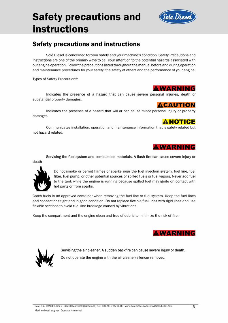
Types of Safety Precautions:
Indicates the presence of a hazard that can cause severe personal injuries, death or
substantial property damages.
Indicates the presence of a hazard that will or can cause minor personal injury or property
damages.
Communicates installation, operation and maintenance information that is safety related but
not hazard related.
Servicing the fuel system and combustible materials. A flash fire can cause severe injury or
death
Do not smoke or permit flames or sparks near the fuel injection system, fuel line, fuel
filter, fuel pump, or other potential sources of spilled fuels or fuel vapors. Never add fuel
to the tank while the engine is running because spilled fuel may ignite on contact with
hot parts or from sparks.
Catch fuels in an approved container when removing the fuel line or fuel system. Keep the fuel lines
and connections tight and in good condition. Do not replace flexible fuel lines with rigid lines and use
flexible sections to avoid fuel line breakage caused by vibrations.
Keep the compartment and the engine clean and free of debris to minimize the risk of fire.
Servicing the air cleaner. A sudden backfire can cause severe injury or death.
Do not operate the engine with the air cleaner/silencer removed.
Solé, S.A. C-243 b, km 2 · 08760 Martorell (Barcelona) ·Tel. +34 93 775 14 00 · www.solediesel.com · [email protected] 7 Marine diesel engines. Operator’s manual
Safety precautions and
instructions
Combustible materials. A fire can cause severe injury or death.
Engine fuels, fuel vapors and combustible materials are flammable and explosive.
Handle these materials carefully to minimize the risk of fire or explosion. Equip the
compartment or nearby area with a fully charged fire extinguisher.
In case of fire do not open sound shield compartment and follow these instructions:
- Shut down engine(s)
- Continuously discharge entire contents of a halon or CO2 portable fire extinguisher
(or other provision) immediately.
Carbon monoxide (CO) can cause severe nausea, fainting or death.
Engine exhaust gases contains carbon monoxide gas. Carbon monoxide is an
odourless, colourless, tasteless, no irritating gas that can cause death if inhaled for
even a short time.
Get fresh air and do not sit, lie down or fall asleep if anyone shows signs of carbon
monoxide poisoning:
- Light-headedness, dizziness
- Physical fatigue, weakness in joints and muscles. Sleepiness, mental fatigue,
inability to concentrate or speak clearly, blurred vision. Stomachache, vomiting,
nausea.
Keep the area around the battery well ventilated. While the engine is running or the battery is
charging, hydrogen gas is produced which can be easily ignited.
Never allow battery fluid (battery contains sulfuric acid) to come in contact with
clothing, skin or eyes. Always wear safety gloves and protective clothing when servicing
the battery. If battery fluid contacts the eyes and/or skin, immediately flush the
affected area with a large amount of clean water and obtain prompt medical treatment.
Moving parts. Keep hands, feet, hair, clothing and test leads away from the
belts and pulleys when the engine is running. Replace guards, screens and
covers before operating the engine.
Solé, S.A. C-243 b, km 2 · 08760 Martorell (Barcelona) ·Tel. +34 93 775 14 00 · www.solediesel.com · [email protected] 8 Marine diesel engines. Operator’s manual
Safety precautions and
instructions
Before working on the engine or connected equipment, disable the engine as follows:
Set the engine controller to OFF position.
(1) Disconnect the power input from battery.
(2) Disconnect the battery cables. Remove the negative (-) lead first when
disconnecting the battery. Reconnect the negative (-) lead last when reconnecting the
battery.
Follow these precautions to prevent the starting of the engine by engine controller, remote
start/stop switch, or engine start command from a remote computer.
Never remove the cooler cap if the engine is hot. Steam and hot engine coolant will
spurt out and seriously burn you. Allow the engine to cool down before you attempt to
remove the cooler cap.
Read the engine operator's manual and understand it before operation and maintenance of
the engine, to ensure that it continues operating practices and maintenance procedures.
Hearing protection. Use to avoid hearing loss when handling the motor.
1. The installer/operator of the engine has to wear suitable CLOTHING for the workplace and the
situation; in particular, avoid loose clothes, chains, bracelets, rings and all accessories that
could become entangled with moving parts.
2. The installer/operator of the engine has to wear personal protective equipment such as
gloves, work shoes, eye and hearing protection as required by the task.
3. The area in which the operator is working has to be kept tidy and free of oil and other liquid
spillages and solid waste (metal chips, etc.).

Solé, S.A. C-243 b, km 2 · 08760 Martorell (Barcelona) ·Tel. +34 93 775 14 00 · www.solediesel.com · [email protected] 9 Marine diesel engines. Operator’s manual
Safety precautions and
instructions Engine labels
If the engine does not start after several attempts to crank
may cause water entering the engine. In this situation it is
recommended:
1) Close the seacock.
2) Drain the water from the exhaust system in the
water trap.
3) Do not try to restart the engine until the cause of
the start fail is identified.
The engine and the gearbox are supplied without any fluid inside.
Consult the manual to follow the installation procedure and
commissioning as well as the fluid capacity - coolant, oil and oil of
gearbox -.
Dangerous voltage. Operate the engine only when all guards and electrical panels are ready.
Hot parts, coolant and steam. Stop the engine and let it cool
down before touching or removing any engine part.
Moving parts. Keep hands, feet, hair, clothing and test leads
away from the belts and pulleys when the engine is running.
Replace guards, screens and covers before operating the
engine.
Heavy Material. Engine is a heavy element, use the right tools
for transportation and handling.
Do not use the motor as a step. Use it as a step can cause
engine damage plus cause undesired operation.
Connection point of the battery cables to the engine. Red cable (positive)
and black cable (negative).
Engine exhaust line installation label, above and below the waterline. See 6.7. Intake and
exhaust system.

Solé, S.A. C-243 b, km 2 · 08760 Martorell (Barcelona) ·Tel. +34 93 775 14 00 · www.solediesel.com · [email protected] 10 Marine diesel engines. Operator’s manual
Solé Diesel warranty
Solé Diesel warranty
Read the manual and documents delivered with each engine before carrying out any of the
operations or presenting any queries. The engine is supplied without any liquids. Ensure that the
liquids used match the specifications contained in Solé Diesel manuals.
The application of the conditions described in this document shall only be effective for engines
or generator sets that have been invoiced after January 1, 2012.
Solé Diesel limited warranty
Solé Diesel guarantees that at the time of shipment all its engines and generator sets comply
with the provided specifications and do not have any manufacturing defects.
The limited warranty provided by Solé Diesel enters into force from the time of sale
to the firs end-purchaser or user of the engine or generator ser. In the event that the product is not
immediately delivered to the end-customer, the warranty shall enter into force 6 months after the date
of sale. Any limited warranty period that has not elapsed can be transferred to the following purchaser
(s).
Unless authorized otherwise by Solé Diesel, the warranty periods are applied
according to the time elapsed in months from the date of purchase or the limit of hours of operation
(whichever occurs first) listed in the following table:
Solé Diesel extended warranty
Solé Diesel an extended period of coverage for the following components: engine block,
cylinder head, crankshaft, camshaft, flywheel housing, timing gear housing, timing gear, conrod.
Limited Warranty Coverage Periods
Product Pleasure Work
Months Hours Months Hours
Propulsion Engines 24 1000 12 2000
Generators sets 24 1000 12 1000
Extended Coverage Periods
Product Pleasure Work
Months Hours Months Hours
Propulsion Engines 36 1500 - -
Generators sets 36 1000 - -
Solé, S.A. C-243 b, km 2 · 08760 Martorell (Barcelona) ·Tel. +34 93 775 14 00 · www.solediesel.com · [email protected] 11 Marine diesel engines. Operator’s manual
Solé Diesel warranty
Restrictions
Coverage:
a) To validate the warranty is necessary fill and send the inspection prior to the delivery of
propulsion engines or genset to Solé Diesel through an official installer. See SECTION 13.
b) The warranty covers any failure of the product under normal opera- ting conditions caused
by a defect in manufacturing.
c) The warranty covers the labour costs necessary to replace and/or repair the defective
original components, according to Solé Diesel standards of excellence. The time period
covered for these operatio- ns is limited to 4 hours.
d) The warranty covers reasonable costs of travel required to carry out the necessary
operations. The travel distance is limited to 300 kilome- tres in conjunction to a travel time
of 3 hours.
Excluded from coverage:
a) If Solé Diesel products are installed and used alongside other products not designed or
manufactured by Solé Diesel that affect their operation, the warranty shall apply exclusively to
the Solé Diesel products and shall not apply if the products from another manufacturer are
inappropriate for use alongside Solé Diesel products or are the cause of the failure or poor
operation of our products.
b) The warranty doesn’t will be effective if don't filled correctly and send the inspection prior to the
delivery of propulsion engines and genset to Solé through an official installer. SECTION 13.
c) The warranty shall not apply if the revisions and maintenance services indicated in the User and
Maintenance Manuals have not been adhered to properly. In case of implemented warranty,
supporting document of the revisions and maintenance service should be exhibited, proving the
requirements outlined in the manuals have been followed.
d) Deterioration resulting from time of storage exceeding 6 months and/or storage conditions that
do not comply with the procedures described in the User and Maintenance Manuals.
e) Deterioration resulting from not complying with the procedure for winter storage while the engine
is not in service, as described in the User and Maintenance Manuals.
f) Faults due to negligence, lack of service, accidents, abnormal use and inadequate service or
installation.
g) Faults due to the use of components not manufactured or sold by Solé Diesel.
h) Faults due to electrical installations that do not comply with Solé Diesel design specifications or
are not expressly approved by Solé Diesel.
i) Faults due to the use of and operation with fuels, oils or lubricants that are not authorised by Solé
Diesel.
j) Faults due to water entering the cylinder(s) through the exhaust system.
k) Faults in propulsion engines due to the use of a propeller that is inadequate for the load or
application. We recommend contacting Solé Diesel to consult the choice of the correct
propeller(s).
l) Failure for general omission of the procedures described in the User and Maintenance Manuals.
m) Components subjected to normal operating wear and tear.
n) Costs due to phone communications, loss of time or money, discomfort, launching, grounding,
removal or replacement of vessel parts or materials because the design of the vessel makes it
necessary to do so to access the engine, and damage and/or accidents caused as a result of a
failure.
Solé, S.A. C-243 b, km 2 · 08760 Martorell (Barcelona) ·Tel. +34 93 775 14 00 · www.solediesel.com · [email protected] 12 Marine diesel engines. Operator’s manual
Solé Diesel warranty
Responsibilities
Responsibilities of the manufacturer:
The obligations of Solé Diesel are restricted to repairing the defective parts or, IF DEEMED
APPROPRIATE BY SOLÉ DIESEL, returning the amount of the purchase or replacing the parts to prevent
poor operation resulting from defective materials or faults in the manufacture covered by the warranty.
Solé Diesel reserves the right to modify the design of any of its products without taking on any
obligation to modify a product that has been manufactured previously.
This manual, as well as technical documentation, manuals or pamphlets may undergo
modifications without prior notice.
Responsibilities of the purchaser:
The purchaser shall be responsible for the care, operation and maintenance of the product
in compliance with the contents of the User and Maintenance Manuals. The purchaser shall provide
proof of all the maintenance services performed on the product. The costs of said services and that
of the components and liquids replaced during said services shall be at the expense of the
purchaser.
The maintenance operations described in this manual shall be performed during the
Warranty Contract Periods (Limited and Extended Coverage) by an AUTHORISED SOLÉ DIESEL
DEALER. Non-compliance with this condition shall void the warranty in all its terms. In such an event,
the materials (oil, filters, etc.) and labour involved shall be at the expense of the purchaser. The
purchaser should keep the invoice of the work performed as proof.
If the service is not covered by the warranty, the purchaser must pay for all labour
performed, the associated materials and any other expense related to the service.
All shipments of products or components sent by the purchaser for inspection and repair
shall be paid in advance by the purchaser.
After-sales service contact Claims shall be presented during the warranty period to the nearest authorized Solé Diesel
dealer (see chart of Solé Diesel Dealers), who shall take care the service covered by the warranty.
The purchaser must provide a proof of purchase and date of purchase by presenting the
invoice to the authorized dealer for the purchase of the product served or a copy of it. Claims under
warranty shall not be dealt with by the dealer until the date of purchase has been verified.
The following information must also be provided by the purchaser:
a) Owner’s name, address and contact telephone number.
b) Product model and serial number.
c) Number of service hours of the product.
d) Detailed description of the problem.
e) Information regarding any repair or installation performed by a service not included in the
Solé Diesel distribution network, as well as the services performed.
For an updated list of our distribution network, visit Dealers section in our web page
www.solediesel.com
e-mail: [email protected]
Phone: +34 93 775 14 00Or request this information by contacting Solé Diesel at:

13
Engine information
Solé, S.A. C- Solé, S.A. C-243 b, km 2 · 08760 Martorell (Barcelona) ·Tel. +34 93 775 14 00 · www.solediesel.com · [email protected]
Operator’s Manual Marine Diesel Engines.
Section 1 – Engine information
1.1. Engine Identification
Identification label:
The nameplate is located above the refrigerator, for MINI-
17 and MINI-29, and on top of the rocker cover for the MINI-33,
MINI-44 and MINI-55.
Engine serial number:
In addition, all engines are marked with the serial number on the block.

Solé, S.A. C-243 b, km 2 · 08760 Martorell (Barcelona) ·Tel. +34 93 775 14 00 · www.solediesel.com · [email protected] 14 Marine diesel engines. Operator’s manual
Engine information
1.2. Engine parts identification
PIECE ELEMENT
1 Oil filler cap
2 Alternator
3 Cooling system
4 Starter
5 Cooling drain plug
6 Gearbox control lever
7 Fuel pump
8 Fuel filter
9 Relays cover
PIECE ELEMENT
10 Air filter
11 Solenoid switch
12 Oil filter
13 Injection pump
14 Seawater pump
15 Bolt engine hanger
16 Oil dipstick
17 Turbocharger
Solé, S.A. C-243 b, km 2 · 08760 Martorell (Barcelona) ·Tel. +34 93 775 14 00 · www.solediesel.com · [email protected] 15 Marine diesel engines. Operator’s manual
Transport, handling and
storage
Section 2 – Transport, handling and storage
2.1. Reception
When the engine is delivered make sure that the packing has not been damaged during
transport and that it has not been tampered with or that components inside the packing have been
removed (see information marked on covers, bases and cartons).
Place the packed engine as close as possible to the place of installation and remove the
packing material, checking that the goods supplied correspond to the order specifications.
If you notice damage or missing parts, inform SOLÉ S.A. after-sales departments and the
carrier immediately and forward photographic evidence of the damage.
After inspecting the goods if you notice damage, write a reservation on the delivery note. Have
the carrier countersign the note and advise SOLÉ S.A., preferably by mail ([email protected]).
2.2. Transport and handling the packed engine
When lifting and transporting the engine use EXCLUSIVELY a forklift or bridge crane of
appropriate load capacity, with chains equipped with safety hooks suitable for lifting the load.
The use of any other system automatically invalidates the insurance guarantee against
possible damage to the engine.
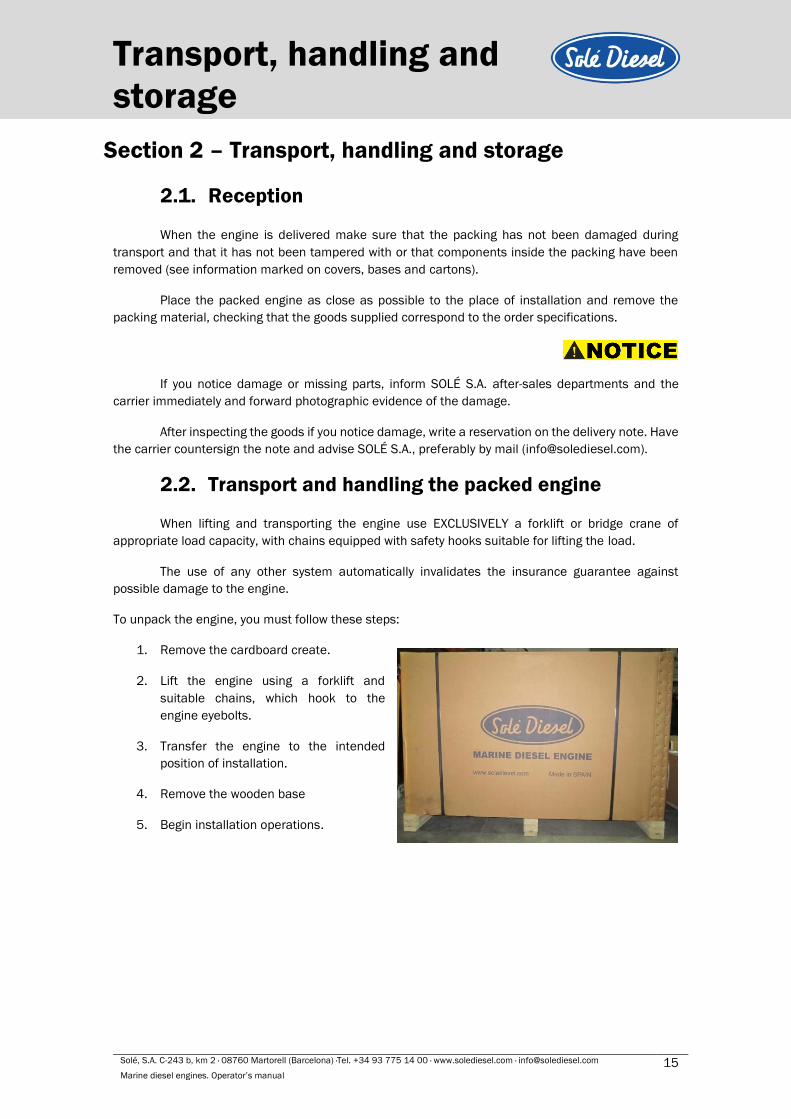
To unpack the engine, you must follow these steps:
1. Remove the cardboard create.
2. Lift the engine using a forklift and
suitable chains, which hook to the
engine eyebolts.
3. Transfer the engine to the intended
position of installation.
4. Remove the wooden base
5. Begin installation operations.
Solé, S.A. C-243 b, km 2 · 08760 Martorell (Barcelona) ·Tel. +34 93 775 14 00 · www.solediesel.com · [email protected] 16 Marine diesel engines. Operator’s manual
Transport, handling and
storage
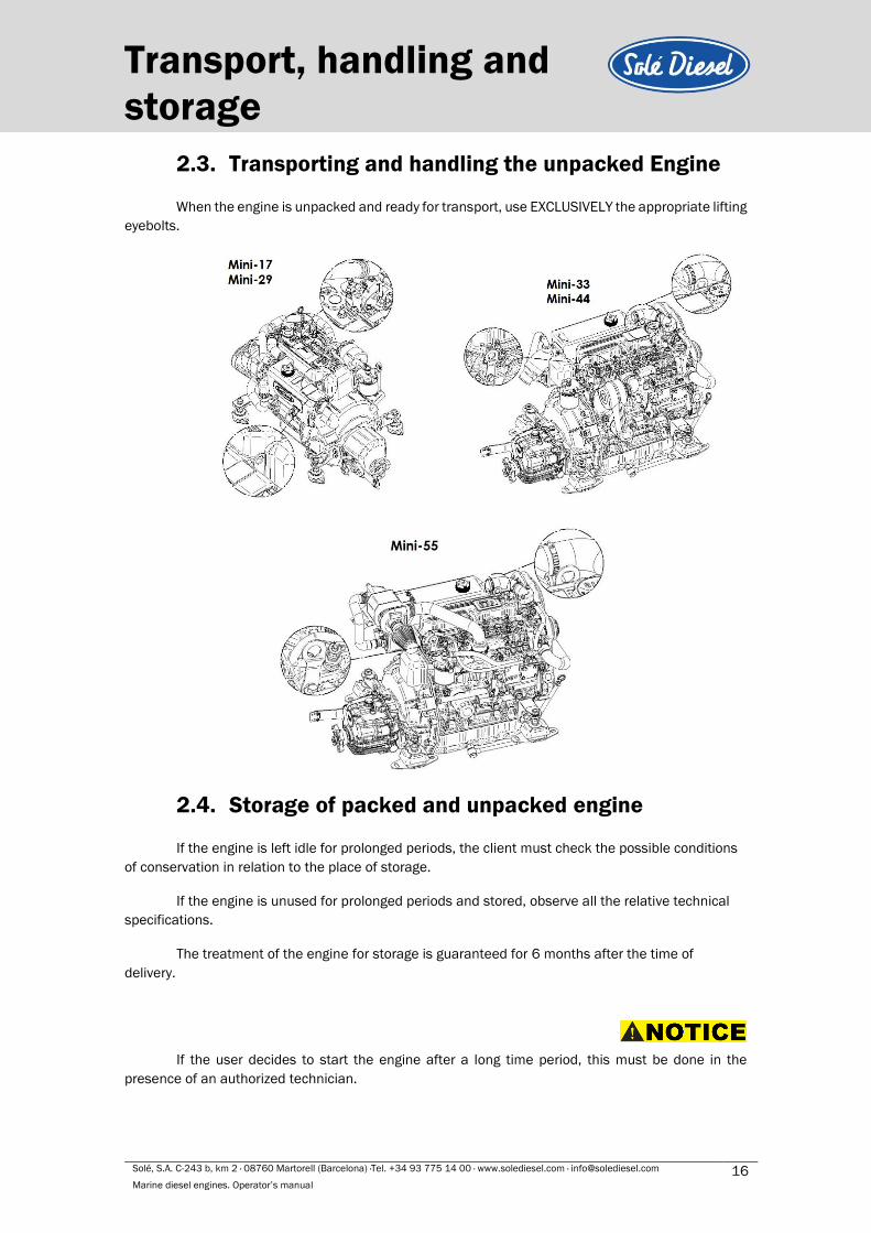
2.3. Transporting and handling the unpacked Engine
When the engine is unpacked and ready for transport, use EXCLUSIVELY the appropriate lifting
eyebolts.
2.4. Storage of packed and unpacked engine
If the engine is left idle for prolonged periods, the client must check the possible conditions
of conservation in relation to the place of storage.
If the engine is unused for prolonged periods and stored, observe all the relative technical
specifications.
The treatment of the engine for storage is guaranteed for 6 months after the time of
delivery.
If the user decides to start the engine after a long time period, this must be done in the
presence of an authorized technician.
Solé, S.A. C-243 b, km 2 · 08760 Martorell (Barcelona) ·Tel. +34 93 775 14 00 · www.solediesel.com · [email protected] 17 Marine diesel engines. Operator’s manual
Installation Section 3 - Installation
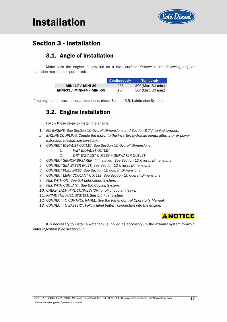
3.1. Angle of installation
Make sure the engine is installed on a level surface. Otherwise, the following angular
operation maximum is permitted:
Continuously Temporaly
MINI-17 / MINI-29 25º 30º (Max. 30 min.)
MINI-33 / MINI-44 / MINI-55 15º 30º (Max. 30 min.)
If the engine operates in these conditions, check Section 5.5. Lubrication System.
3.2. Engine Installation
Follow these steps to install the engine:
1. FIX ENGINE. See Section 10 Overall Dimensions and Section 8 Tightening torques.
2. ENGINE COUPLING. Couple the motor to the inverter, hydraulic pump, alternator or power
extraction mechanism correctly.
3. CONNECT EXHAUST OUTLET. See Section 10 Overall Dimensions
1. WET EXHAUST OUTLET
2. DRY EXHAUST OUTLET + SEAWATER OUTLET
4. CONNECT SIPHON BREAKER. (if installed) See Section 10 Overall Dimensions
5. CONNECT SEAWATER INLET. See Section 10 Overall Dimensions
6. CONNECT FUEL INLET. See Section 10 Overall Dimensions
7. CONNECT LEAK COOLANT OUTLET. See Section 10 Overall Dimensions
8. FILL WITH OIL. See 5.4 Lubrication System.
9. FILL WITH COOLANT. See 5.6 Cooling System.
10. CHECK EACH PIPE CONNECTION for oil or coolant leaks.
11. PRIME THE FUEL SYSTEM. See 5.5 Fuel System
12. CONNECT TO CONTROL PANEL. See the Panel Control Operator’s Manual..
13. CONNECT TO BATTERY. Follow label battery connection into the engine.
It is necessary to install a waterlock (supplied as accessory) in the exhaust system to avoid
water ingestion (See section 5.7)

Solé, S.A. C-243 b, km 2 · 08760 Martorell (Barcelona) ·Tel. +34 93 775 14 00 · www.solediesel.com · [email protected] 18 Marine diesel engines. Operator’s manual
Operation
Section 4 - Operation
4.1. Prestart checklist
Follow these checks and inspections to ensure the correct engine operation. In addition, some
checks require verification after unit starts.
AIR CLEANER: Check for a clean and installed air cleaner element to prevent unfiltered air
from entering the engine.
AIR INLETS: Check for clean and unobstructed air inlets.
BATTERY: Check for tight battery connections.
COOLANT LEVEL: Check the coolant level according to coolant circuit capacity.
DRIVE BELTS: Check the belt condition and tension of the coolant pump and battery charging
alternator belt.
EXHAUST SYSTEM: Check for exhaust leaks and blockages. Check the silencer and piping
condition and check for tight exhaust system connections.
Check that the exhaust outlet is unobstructed.
FUEL LEVEL: Check the fuel level and keep the tank(s) full to ensure adequate fuel supply.
OIL LEVEL: Maintain the oil level below dipstick high mark and above dipstick low mark.
OPERATING AREA: Check for obstructions that could block the flow of admission air.
SEAWATER PUMP PRIMING: Prime the seawater pump before initial startup. To prime the
pump:
- Close the seacock
- Remove the hose from the seawater-filter outlet
- Fill the hose and seawater pump with clean water
- Reconnect the hose to the water filter outlet
- Open the seacock
Confirm seawater pump operation on startup as indicated by water discharge from the
exhaust outlet.
4.2. Cranking the engine
1. TURN ON THE KEY POSITION. To start all instruments with fuel
pump.
2. TURN THE KEY TO PREHEATING POSITION. To heat the engine
for a few seconds before the start.
3. TURN THE KEY TO STARTER POSITION. To feed the starter and
start the engine.
Solé, S.A. C-243 b, km 2 · 08760 Martorell (Barcelona) ·Tel. +34 93 775 14 00 · www.solediesel.com · [email protected] 19 Marine diesel engines. Operator’s manual
Operation If the engine doesn't start after several attempts to start, may cause water entering in the
engine. See warning label on the engine.
After starting up the engine, check the following points. If you find anything wrong, immediately
stop the engine, and then investigate the cause.
1. Lubrication oil pressure should be from 0,29 to 0,39 MPa (3 to 4 kgf/cm2) (2,9 to 3,9
bar) at nominal speed.
2. Coolant temperature should be 75 to 85ºC.
3. Oil temperature should be 60 to 95ºC.
4. Check for leakage of oil, coolant and fuel.
5. Knocking should die away as coolant temperature rises. No other defective noise should
be heard.
6. Check for exhaust colour and abnormal odours.
4.3. Stopping engine
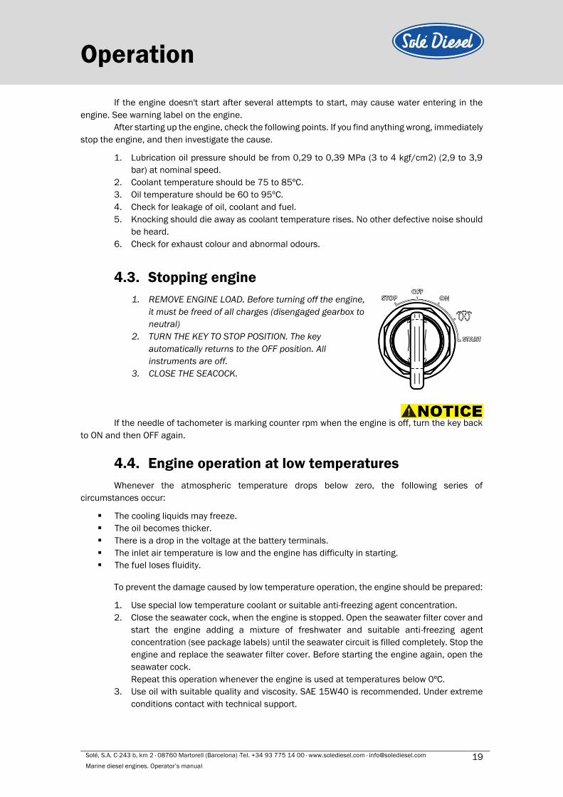
1. REMOVE ENGINE LOAD. Before turning off the engine,
it must be freed of all charges (disengaged gearbox to
neutral)
2. TURN THE KEY TO STOP POSITION. The key
automatically returns to the OFF position. All
instruments are off.
3. CLOSE THE SEACOCK.
If the needle of tachometer is marking counter rpm when the engine is off, turn the key back
to ON and then OFF again.
4.4. Engine operation at low temperatures
Whenever the atmospheric temperature drops below zero, the following series of
circumstances occur:
▪ The cooling liquids may freeze.
▪ The oil becomes thicker.
▪ There is a drop in the voltage at the battery terminals.
▪ The inlet air temperature is low and the engine has difficulty in starting.
▪ The fuel loses fluidity.
To prevent the damage caused by low temperature operation, the engine should be prepared:
1. Use special low temperature coolant or suitable anti-freezing agent concentration.
2. Close the seawater cock, when the engine is stopped. Open the seawater filter cover and
start the engine adding a mixture of freshwater and suitable anti-freezing agent
concentration (see package labels) until the seawater circuit is filled completely. Stop the
engine and replace the seawater filter cover. Before starting the engine again, open the
seawater cock.
Repeat this operation whenever the engine is used at temperatures below 0ºC.
3. Use oil with suitable quality and viscosity. SAE 15W40 is recommended. Under extreme
conditions contact with technical support.
Solé, S.A. C-243 b, km 2 · 08760 Martorell (Barcelona) ·Tel. +34 93 775 14 00 · www.solediesel.com · [email protected] 20 Marine diesel engines. Operator’s manual
Operation 4. Cover battery with an adequate material to protect it against the cold. Check that the
battery is fully charged.
It is also advisable to use a dielectric spray on the electrical connections.
5. When starting the engine, make sure that the glow plugs become hot enough.
6. If necessary, replace the diesel oil by a specified diesel oil type for low temperatures.
The accumulation of impurities in the fuel tank could cause faulty firing.
All engines not in use are subject to rusting and corrosion of machined surfaces that are not
protected with a paint coating. The degree of corrosion depends on meteorological changes and
climatic conditions. The following recommendations are therefore of a general nature but they will help
prevent or reduce the risk of damage due to rusting.
4.5. Winterization and preservation
If the boat is not going to be used for a long period of time or during the winter, certain tasks
must be carried out to keep it in perfect operating condition. Follow the steps indicated below carefully:
1. Clean the outer surface of the engine.
2. Bleed the seawater circuit by filling it with fresh water. Fill the seawater circuit again with a
mixture of fresh water and anti-freezing agent.
3. Remove the impeller from the seawater pump, clean it with fresh water and store it in place
protected from moisture and sunlight.
4. Renew and refill the heat exchanger to the maximum level with a mixture of fresh water and
anti-freezing agent.
5. Renew the oil in the engine.
6. Cover the air intake.
7. If the fuel tank is small, empty it completely and clean it; fill it up again with a mixture of
diesel and anti-corrosion additive. Solé S.A. recommends DIECYL PLUS. Add one measure of
this additive for every 25 liters of diesel. On the other hand, if the fuel tank is large, add 1
liter of this additive for every 500 liters of diesel.
8. Clean and dry the area where the engine is installed.
9. Loosen the belts.
10. Apply dielectric spray on the electrical connection, disassemble the battery and charge it
several times during the time it is not being used.
11. Apply moisture repellent spray on the motor.
Solé, S.A. C-243 b, km 2 · 08760 Martorell (Barcelona) ·Tel. +34 93 775 14 00 · www.solediesel.com · [email protected] 21 Marine diesel engines. Operator’s manual
Operation 4.6. Maintenance during the storage
During the long engine storage, it has to be stored inside a ventilated area and free of
humidity.
When the engine stay stopped for 3 months or more, inside parts can be oxidize and lost the
oil film. As a result, the engine could to size up after the storage. To avoid this, the engine must work
periodically during the storage.
Realize the following steps at least once per month:
1. In case that has a battery next to the engine, check the electrolyte level and fill it.
2. Start the engine during approximately 10 seconds.
3. Stop the engine during 1 minute. Repeat this action two or three times.
4. Be sure that oil pressure of the engine increase.
5. Get the engine work during 5 or 10 minutes without load, as maintenance operation.
4.7. Restoration of operational conditions
When starting up the engine again after winter lay-up, certain operations must be
performed. Follow these steps:
1. Fill the fuel tank with clean diesel. The mixture of diesel oil and anti-corrosion additive in
tank for winter lay-up can be used to operate the engine.
2. Check the fuel filter. If the filter is clogged, replace the filter.
3. Renew the oil in the engine.
4. Check the condition of coolant circuit’s rubber hoses.
5. Reconnect the battery and apply a layer of neutral Vaseline to the battery terminals.
6. Remove the nozzle supports and clean them. If possible, verify the setting of the nozzles
at a workshop. Then install the clean nozzles.
7. Connect the cooling and exhaust system. Open the seawater cock.
8. Verify whether there are any leaks in the fuel, coolant and oil systems.

Solé, S.A. C-243 b, km 2 · 08760 Martorell (Barcelona) ·Tel. +34 93 775 14 00 · www.solediesel.com · [email protected] 22 Marine diesel engines. Operator’s manual
Section 5 – Systems and scheduled maintenance
5.1. Safety and prevention Information of special tools required and basic safety precautions.
Disassembly:
✓ Use the correct tools and instruments. Serious injury or damage to the engine can result
from using the wrong tools and instruments.
✓ Use an overhaul stand or work bench if necessary. Also, use assembly bins to keep the
engine parts in order of removal.
✓ Lay down disassembled or cleaned parts in the order in which they were removed. This
will save you time at reassembly.
✓ Pay attention to the marks on assemblies, components and parts for positions or
directions. Put on your own marks, if necessary, to aid reassembly.
✓ Carefully check each part for faults during removal or cleaning. Signs of abnormal wear
will tell if parts or assemblies are functioning improperly.
✓ When lifting or carrying heavy parts, get someone to help you if the part is too awkward
for one person to handle. Use jacks and chain blocks when necessary.
Reassembly:
✓ Wash all engine parts, except oil seals, O-rings, rubber seals, etc. in cleaning solvent and
dry them.
✓ Use only the correct tools and instruments.
✓ Use only good quality lubricating oils and greases. Be sure to apply a coat of oil, grease,
or sealant to parts as specified.
✓ Use a torque wrench to tighten parts when specified tightening torques is required.
✓ Replace all gaskets and packing. Apply appropriate amount of adhesive or liquid gasket
when required.
✓ Increase the frequency of maintenance in harsh duty conditions (frequent stops and
starts, dusty surrounding, prolonged winter season, no-load running).
✓ Risk of burns during maintenance operations carried out when the engine is hot. Wear
suitable safety clothing.
✓ It is strictly forbidden to clean the engine with compressed air.
✓ It is strictly forbidden to perform maintenance/cleaning operations in the presence of
moving parts.
✓ Use gloves, overalls, etc. to protect the body from burns.
5.2. Periodic maintenance schedule The maintenance and fault diagnostic procedures involve risks that may cause severe injury
or even death. These procedures should therefore be carried out solely by qualified electrical and
mechanical specialists. Before any maintenance and cleaning work, make sure that there are no
moving parts that the generator housing has cooled to ambient temperature, that the electricity
generating set cannot be accidentally started up and that all procedures are strictly observed.
Systems and scheduled
maintenance

Solé, S.A. C-243 b, km 2 · 08760 Martorell (Barcelona) ·Tel. +34 93 775 14 00 · www.solediesel.com · [email protected] 23 Marine diesel engines. Operator’s manual
Systems and scheduled
maintenanceIntervals
Inspection Item Daily 1st 20h-
50h
Every
200h
Every
400h
Every
800h
Every
year
Every 2
years
Winter storage and
Preservation
General
Screw tightening, fastening. I I
Engine block. CL
Valve clearance. I
Exhaust gas, noise and vibrations. I
Compression pressure. I
Lubrication
system*
Engine oil. I C C C C
Oil filter. C C
Fuel sistem
Fuel level. I
Fuel tank. CL E/CL/I
Fuel filter. C
Water separator filter (if applicable). E C
Injection pump. I
Injector. I
Intake system Air filter. I C C I
Cooling system
Coolant. I C C
Sea water circuit. I/CL
Anode. I/C
Water filter. I CL CL
Sea water cock. I
Sea water pump impeller. I/C I I/CL
Electrical system
Incandescent glow plug. I
Starter motor and alternator 12/24V. I
Alternator 12/24V belt and tension. I I C I
Battery level. I I C
*Use oil with 15W40 viscosity and no less than ACEA E5 or API CH-4/SJ quality. I: Inspect, adjust or fill. E: Empty. C: Change. CL: Clean.
Solé, S.A. C-243 b, km 2 · 08760 Martorell (Barcelona) ·Tel. +34 93 775 14 00 · www.solediesel.com · [email protected] 24 Marine diesel engines. Operator’s manual
Systems and scheduled
maintenance
5.3. General Solé Diesel offers, for these engine models, the several Pack, consult on the web.
• Welcome pack.
• On board pack.
• Maintenance pack 50 hours.
• Maintenance pack 1600 hours.
• Maintenance pack 3000 hours.
Maintenance task. Screw tightening, fastening
For details of tightening torques see Section 8 Torques.
Maintenance task. Valve clearance inspection
The rocker cover must be dismounted to check the valve clearance. This operation must be
carried out when the engine is cold.
Item Assembly standard
Valve clearance (cold setting) Inlet
0,25 mm Exhaust
Inspection
1. Inspect the valve clearance in the injection sequence. To check, turn the crankshaft by the
specified crank angle in the normal direction to bring the piston to the top dead center of the
compression stroke.
Injection sequence Crank angle
MINI-17 1 - 2 240º
MINI-29 MINI-33 1 - 3 - 2 240º
MINI-44 MINI-55 1 – 3 - 4 - 2 180º
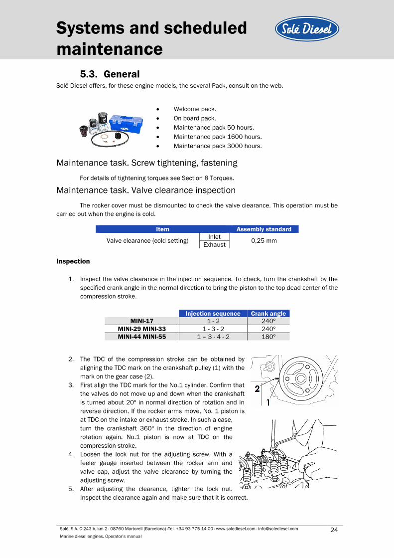
2. The TDC of the compression stroke can be obtained by
aligning the TDC mark on the crankshaft pulley (1) with the
mark on the gear case (2).
3. First align the TDC mark for the No.1 cylinder. Confirm that
the valves do not move up and down when the crankshaft
is turned about 20º in normal direction of rotation and in
reverse direction. If the rocker arms move, No. 1 piston is
at TDC on the intake or exhaust stroke. In such a case,
turn the crankshaft 360º in the direction of engine
rotation again. No.1 piston is now at TDC on the
compression stroke.
4. Loosen the lock nut for the adjusting screw. With a
feeler gauge inserted between the rocker arm and
valve cap, adjust the valve clearance by turning the
adjusting screw.
5. After adjusting the clearance, tighten the lock nut.
Inspect the clearance again and make sure that it is correct.

Solé, S.A. C-243 b, km 2 · 08760 Martorell (Barcelona) ·Tel. +34 93 775 14 00 · www.solediesel.com · [email protected] 25 Marine diesel engines. Operator’s manual
Systems and scheduled
maintenance 6. Turn the crankshaft 240º or 180º clockwise, according to your engine model (see table 8.
Injection sequence), from TDC of the No.1 cylinder, to set the No.2-cylinder TDC. Repeat from
step 1 to step 6. And the same procedure for No.3 and 4 cylinders.
7. After the valve clearance on the valves for all cylinders has been adjusted, turn the crankshaft
two or three times and make sure the valve clearance is correct.
Valve clearance should be inspected and adjusted when the engine is cold.
Adjusting
1. Loosen the lock nut of the adjusting screw. Adjust the
clearance by turning the screw in either direction to
the extent that the gauge is slightly gripped between
the rocker arm and valve cap.
2. After adjusting the clearance, tighten the lock nut.
Inspect the clearance again and make sure that it is
correct.
Maintenance task. Compression pressure inspection
Start by:
1. Make sure the engine oil level, air cleaner, starting
motor and battery are well-conditioned.
2. Start the engine and allow it to warm up
thoroughly, until 50ºC or more coolant
temperature.
Measure the compression pressure on all cylinders:
1. Remove the injection nozzle from the cylinder head where the compression pressure is to be
measured.
2. Attach the compression pressure gauge.
3. Disconnect the stop solenoid connector (the fuel supply shut off) and crank the engine by
means of the starter and read the compression pressure gauge indication when the engine is
running at specified speed.
4. If the compression pressure is lower than repair limit, check the engine parts affected.
- It is not a good practice to measure the compression pressure on only few cylinders, and
presume the compression on the remaining cylinders.
- Compression pressure varies with engine speed. Check engine speed when measuring the
compression pressure.
Engine
speed Compression pressure Repair limit
Máximum pressure
difference betwen
cylinders
MINI-17 280 rpm 2,7MPa (28 kgf/cm2) 2.2 MPa (22 kgf/cm2) 0,25 MPa (2.5 kgf/cm2)
MINI-29 280 rpm 2,7MPa (28 kgf/cm2) 2.2 MPa (22 kgf/cm2) 0,25 MPa (2.5 kgf/cm2)
MINI-33 290 rpm 2,94MPa (30 kgf/cm2) 2.65 MPa (27
kgf/cm2) 0,29 MPa (3 kgf/cm2)
MINI-44 290 rpm 2,94MPa (30 kgf/cm2) 2.65 MPa (27
kgf/cm2) 0,29 MPa (3 kgf/cm2)
MINI-55 290 rpm 2,94MPa (30 kgf/cm2) 2.65 MPa (27
kgf/cm2) 0,29 MPa (3 kgf/cm2)
- The compression pressure will be slightly higher in a new or overhauled engine due
to new piston rings, valve seats, etc
Solé, S.A. C-243 b, km 2 · 08760 Martorell (Barcelona) ·Tel. +34 93 775 14 00 · www.solediesel.com · [email protected] 26 Marine diesel engines. Operator’s manual
Systems and scheduled
maintenance
5.4. Lubrication system
Circuit description
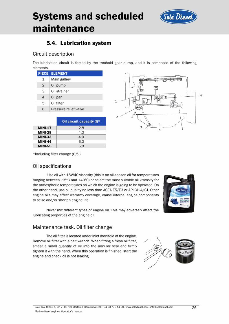
The lubrication circuit is forced by the trochoid gear pump, and it is composed of the following
elements.
PIECE ELEMENT
1 Main gallery
2 Oil pump
3 Oil strainer
4 Oil pan
5 Oil filter
6 Pressure relief valve
*Including filter change (0,5l)
Oil specifications
Use oil with 15W40 viscosity (this is an all-season oil for temperatures
ranging between -15ºC and +40ºC) or select the most suitable oil viscosity for
the atmospheric temperatures on which the engine is going to be operated. On
the other hand, use oil quality no less than ACEA E5/E3 or API CH-4/SJ. Other
engine oils may affect warranty coverage, cause internal engine components
to seize and/or shorten engine life.
Never mix different types of engine oil. This may adversely affect the
lubricating properties of the engine oil.
Maintenance task. Oil filter change
The oil filter is located under inlet manifold of the engine.
Remove oil filter with a belt wrench. When fitting a fresh oil filter,
smear a small quantity of oil into the annular seal and firmly
tighten it with the hand. When this operation is finished, start the
engine and check oil is not leaking.
Oil circuit capacity (l)*
MINI-17 2.8
MINI-29 4,0
MINI-33 4.0
MINI-44 6,0
MINI-55 6,0
Solé, S.A. C-243 b, km 2 · 08760 Martorell (Barcelona) ·Tel. +34 93 775 14 00 · www.solediesel.com · [email protected] 27 Marine diesel engines. Operator’s manual
Systems and scheduled
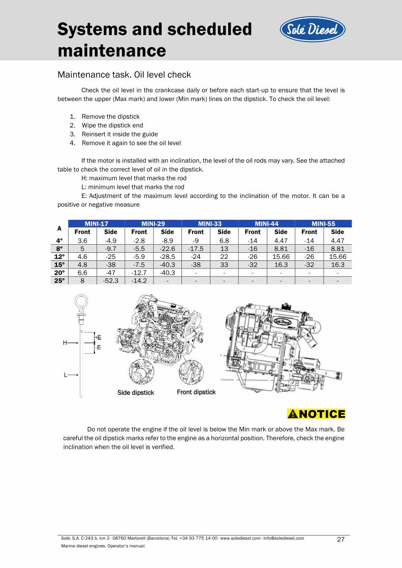
maintenance Maintenance task. Oil level check
Check the oil level in the crankcase daily or before each start-up to ensure that the level is
between the upper (Max mark) and lower (Min mark) lines on the dipstick. To check the oil level:
1. Remove the dipstick
2. Wipe the dipstick end
3. Reinsert it inside the guide
4. Remove it again to see the oil level
If the motor is installed with an inclination, the level of the oil rods may vary. See the attached
table to check the correct level of oil in the dipstick.
H: maximum level that marks the rod
L: minimum level that marks the rod
E: Adjustment of the maximum level according to the inclination of the motor. It can be a
positive or negative measure
A MINI-17 MINI-29 MINI-33 MINI-44 MINI-55
Front Side Front Side Front Side Front Side Front Side
4º 3.6 -4.9 -2.8 -8.9 -9 6.8 -14 4.47 -14 4.47
8º 5 -9.7 -5.5 -22.6 -17.5 13 -16 8.81 -16 8.81
12º 4.6 -25 -5.9 -28.5 -24 22 -26 15.66 -26 15.66
15º 4.8 -38 -7.5 -40.3 -38 33 -32 16.3 -32 16.3
20º 6.6 -47 -12.7 -40.3 - - - - - -
25º 8 -52.3 -14.2 - - - - - - -
Do not operate the engine if the oil level is below the Min mark or above the Max mark. Be
careful the oil dipstick marks refer to the engine as a horizontal position. Therefore, check the engine
inclination when the oil level is verified.
Side dipstick Front dipstick

Solé, S.A. C-243 b, km 2 · 08760 Martorell (Barcelona) ·Tel. +34 93 775 14 00 · www.solediesel.com · [email protected] 28 Marine diesel engines. Operator’s manual
Systems and scheduled
maintenance
Maintenance task. Oil fill/Change
Oil must be changed with hot engine so as to be sure the oil is fully drained. The procedure is
the following:
1. Drain the oil (follow steps below)
a. Stop the engine.
b. Disconnect the battery negative (-) terminal.
c. Remove the oil dipstick.
d. Connect the external oil pump to the end of the oil drain hose. Place the outlet of the
pump into an oil collection container.
e. Allow time for the engine oil to drain completely.
2. Replace the oil filter
3. Remove external oil pump. Do not insert oil dipstick.
4. Fill with oil according to oil capacity circuit.
5. Check for leaks.
6. Check oil level according to the oil level check procedure.
Never overfill. Overfilling may result in white exhaust smoke, engine overspeed or internal
damage. It is important to remove the dipstick to let the air out of the engine while the engine is filled
with oil, otherwise, bubbles can be create that make oil overflowing outside.
5.5. Fuel system
Circuit description
The fuel system is based on a fuel feed pump and an in-line mechanical injection pump.
PIECE ELEMENT
1 Fuel injection Nozzle
2 Fuel injection pipe
3 Fuel return pipe
4 Injection pump
5 Feed pump
6 Fuel filter
7 Tank (supplied as accessory)
8 Fuel decanting filter (accesory)
9 Fuel intake pipe (accessory)
Fuel specifications
Use ASTM diesel fuel No.2-D for the best engine performance, to prevent engine damage.
Never use kerosene, heavy diesel fuel or biodiesel. It is essential to use clean and filtered diesel oil.
The use of diesel oil that not complies with the technical specifications may affect warranty
coverage and cause serious damage in the injection system and internal engine components.
Solé, S.A. C-243 b, km 2 · 08760 Martorell (Barcelona) ·Tel. +34 93 775 14 00 · www.solediesel.com · [email protected] 29 Marine diesel engines. Operator’s manual
Systems and scheduled
maintenance Maintenance task. Fuel level inspection
Periodically, it is necessary to check the fuel level to assure the operation of the engine. On
top of that, if fuel pump sucks air when the fuel level is lower than pump suction, it could break.
Whenever possible, keep the fuel tank full. The temperature changes may cause
condensation of the damp air present in the tank and this water accumulates at the bottom. It can
cause an increase of corrosion or an impossibility of starting the engine if this water is aspired by the
fuel pump.
Maintenance task. Fuel tank clean
The fuel impurities could obstruct the suction pump. For this reason, drain out the content of
the fuel tank to remove condensate and any foreign material. Then, wash the tank with fuel and refill
it.
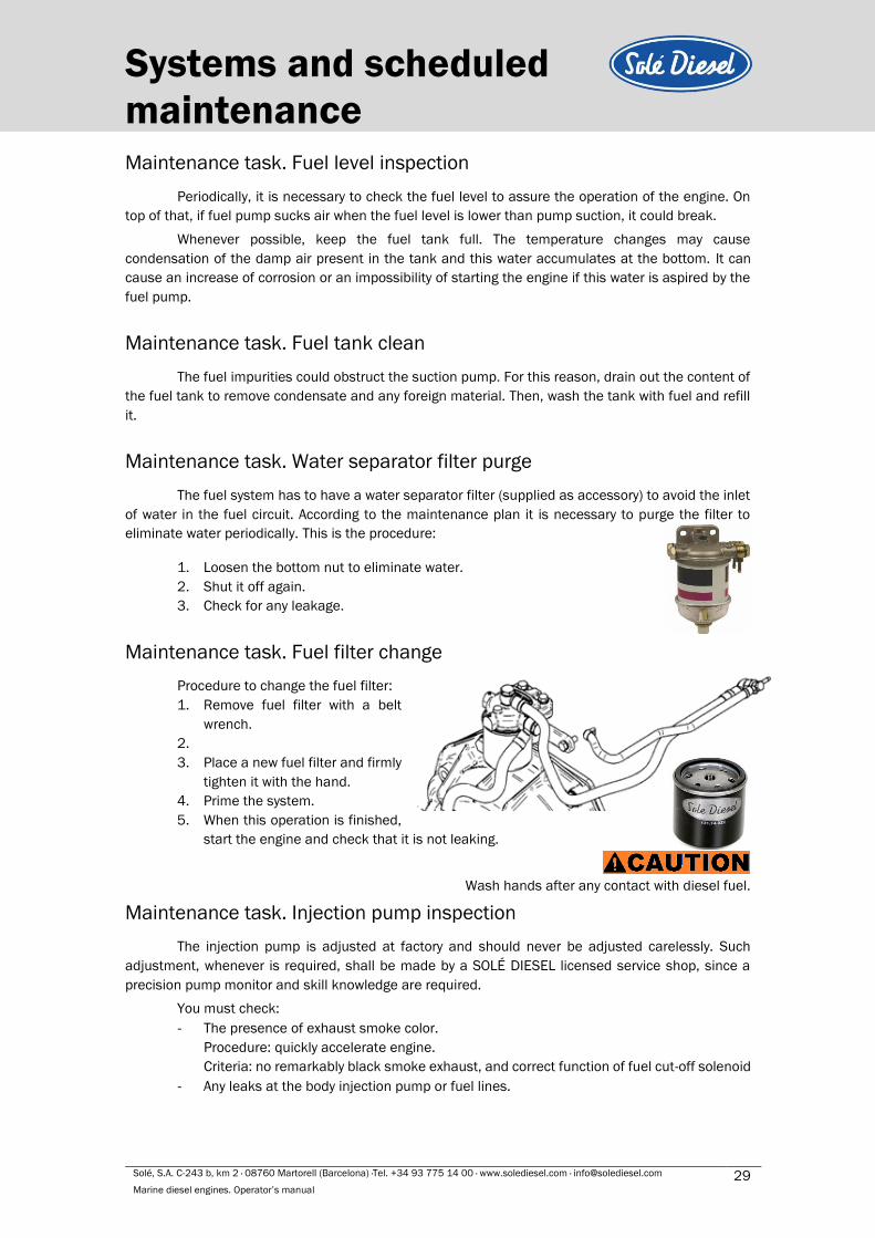
Maintenance task. Water separator filter purge
The fuel system has to have a water separator filter (supplied as accessory) to avoid the inlet
of water in the fuel circuit. According to the maintenance plan it is necessary to purge the filter to
eliminate water periodically. This is the procedure:
1. Loosen the bottom nut to eliminate water.
2. Shut it off again.
3. Check for any leakage.
Maintenance task. Fuel filter change
Procedure to change the fuel filter:
1. Remove fuel filter with a belt
wrench.
2.
3. Place a new fuel filter and firmly
tighten it with the hand.
4. Prime the system.
5. When this operation is finished,
start the engine and check that it is not leaking.
Wash hands after any contact with diesel fuel.
Maintenance task. Injection pump inspection
The injection pump is adjusted at factory and should never be adjusted carelessly. Such
adjustment, whenever is required, shall be made by a SOLÉ DIESEL licensed service shop, since a
precision pump monitor and skill knowledge are required.
You must check:
- The presence of exhaust smoke color.
Procedure: quickly accelerate engine.
Criteria: no remarkably black smoke exhaust, and correct function of fuel cut-off solenoid
- Any leaks at the body injection pump or fuel lines.

Solé, S.A. C-243 b, km 2 · 08760 Martorell (Barcelona) ·Tel. +34 93 775 14 00 · www.solediesel.com · [email protected] 30 Marine diesel engines. Operator’s manual
Systems and scheduled
maintenance
Maintenance task. Injector inspection
To check the injection pressure of injectors
(opening pressure) you have to follow these steps:
1. Remove nozzle and washer.
2. Install the injection nozzle on the tester. Slowly
operate the tester handle full strokes to bleed
(remove) air from the pipe and nozzle.
3. Make a slow increase in pressure by operating the
tester handle at a speed of more than one stroke
per second while observing the pressure gauge.
4. The pressure gauge reading will slowly increase
and, when the nozzle starts discharging fuel, it will
go down fast. Take the gauge reading right then as
the injection pressure.
Injection pressure 13,73 MPa (140 kgf/cm2)
5. To adjust the injection pressure, increase or decrease
the amount of shims fitted to the nozzle holder.
6. Look at the orifice discharge pattern (shape of discharge) when fluid begins to flow through
the injection nozzle. The discharge must be finely and uniformly atomized. Any change is an
indication of a bad nozzle.
7. If the nozzle is bad, remove the tip from the nozzle and wash
needle valve and body in clean washing solution.
And if the nozzle is still bad after the tip has been washed,
replace the tip.
8. When installing the new tip, remove synthetic resin film
from the tip and slide the needle valve in the body in clean
diesel fuel to wash off inhibitor completely.
9. The washer shown on Fig. 29 must be replaced.
When testing the injection nozzle, keep its tip pointed away from the operator. Fuel from the
orifices in the tip of the nozzle is under high pressure and can cause injury to the operator.

Solé, S.A. C-243 b, km 2 · 08760 Martorell (Barcelona) ·Tel. +34 93 775 14 00 · www.solediesel.com · [email protected] 31 Marine diesel engines. Operator’s manual
Systems and scheduled
maintenance Maintenance task. Bleeding air from the fuel system
Prime the fuel system to bleed the air from the circuit. Trapped air in the fuel system can
cause difficult starting and erratic engine operation. It is necessary to prime the system:
✓ Before starting the engine for the first time.
✓ After running out of fuel and adding fuel to the tank.
✓ After fuel system maintenance such as changing the fuel filter, draining the fuel/water
separator, or replacing a fuel system component.
For this operation you have to follow these steps:
1. Loosen all the injection pipes.
2. Start the engine to drive out air in the injection pipes and nozzles automatically.
3. When fuel overflows from an injection pipe, tighten it up and wait until fuel overflows from
another one. Repeat it until all injection pipes are tightened.
4. After bleeding, clean up fuel spillage.
When fuel overflows from the injection pipes, wipe thoroughly with a cloth. Spilled fuel is a fire
hazard.
5.6. Cooling system The engine cooling system is based on coolant circulation controlled by centrifugal pump with
thermostatic control and heat exchanger, where the coolant is refrigerated by sea water. Moreover,
the exhaust manifold is cooled also by sea water.
Coolant circuit capacity (l)
MINI-17 2,7
MINI-29 3,0
MINI-33 5.7
MINI-44 8,0
MINI-55 8,0
COOLANT CIRCUIT DESCRIPTION
PIECE ELEMENT
1 Coolant pump
2 Heat exchanger
3 Thermostat
SEAWATER CIRCUIT DESCRIPTION
PIECE ELEMENT
1 Bottom cock (supplied as
accessory)
2 Sea water filter
3 Sea water pump
4 Heat exchanger
5 Wet exhaust elbow

Solé, S.A. C-243 b, km 2 · 08760 Martorell (Barcelona) ·Tel. +34 93 775 14 00 · www.solediesel.com · [email protected] 32 Marine diesel engines. Operator’s manual
Systems and scheduled
maintenance
Coolant specifications
It is recommended use SOLÉ DIESEL 50% coolant or another coolant with similar
specifications. On the other hand, distilled water with an anti-freezing agent is also suitable. The anti-
freezing agent concentration according to operating conditions is specified in anti-freezing agent
package labels. It is advisable select the anti-freezing agent concentration based on a temperature
approx. 5ºC under the actual atmospheric temperature.
Other engine coolants may affect warranty coverage, cause an internal build-up of rust and
scale and/or shorten engine life.
Never mix different types of coolants. This may adversely affect the properties of the engine
coolant.
Maintenance task. Coolant check
Allow the engine to cool. Release pressure from the cooling system before removing the
pressure cap. To release pressure, cover the pressure cap with a thick cloth and then slowly turn the
cap counterclockwise. Remove the cap after pressure has been completely released and the engine
has cooled. Check the coolant level at the tank, the level must be approximately 3/4 full.
Maintenance task. Coolant fill/change
1. Drain off all the coolant by opening the two drain plugs, one in the heat exchanger and the
other in the cylinder block.
2. Close the drain plugs.
3. Remove bleeding bolt of thermostat holder (only Mini-17/29).
4. Refill to the hole in the tank cap with coolant.
Maintenance task. Seawater filter inspection
It is important to install a seawater filter (supplied as accessory) between seawater cock and
the seawater pump to avoid that any impurity might clog the seawater circuit or seawater pump.
To clean this filter:
1. Loosen the wing nut.
2. Remove the filtering component and clean it.
3. Fit it again taking care that the cover is well
seated on the o-ring.
4. Start the engine to check seawater leakages.
Solé, S.A. C-243 b, km 2 · 08760 Martorell (Barcelona) ·Tel. +34 93 775 14 00 · www.solediesel.com · [email protected] 33 Marine diesel engines. Operator’s manual
Systems and scheduled
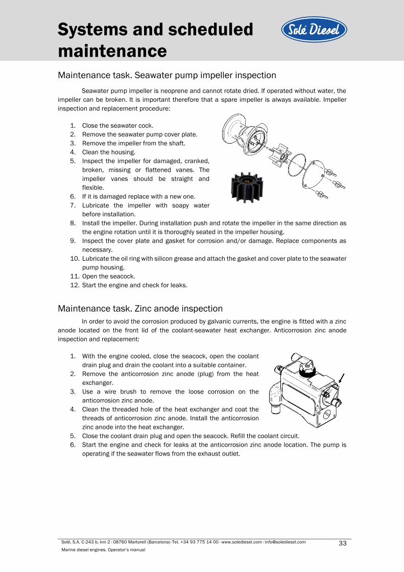
maintenance Maintenance task. Seawater pump impeller inspection
Seawater pump impeller is neoprene and cannot rotate dried. If operated without water, the
impeller can be broken. It is important therefore that a spare impeller is always available. Impeller
inspection and replacement procedure:
1. Close the seawater cock.
2. Remove the seawater pump cover plate.
3. Remove the impeller from the shaft.
4. Clean the housing.
5. Inspect the impeller for damaged, cranked,
broken, missing or flattened vanes. The
impeller vanes should be straight and
flexible.
6. If it is damaged replace with a new one.
7. Lubricate the impeller with soapy water
before installation.
8. Install the impeller. During installation push and rotate the impeller in the same direction as
the engine rotation until it is thoroughly seated in the impeller housing.
9. Inspect the cover plate and gasket for corrosion and/or damage. Replace components as
necessary.
10. Lubricate the oil ring with silicon grease and attach the gasket and cover plate to the seawater
pump housing.
11. Open the seacock.
12. Start the engine and check for leaks.
Maintenance task. Zinc anode inspection
In order to avoid the corrosion produced by galvanic currents, the engine is fitted with a zinc
anode located on the front lid of the coolant-seawater heat exchanger. Anticorrosion zinc anode
inspection and replacement:
1. With the engine cooled, close the seacock, open the coolant
drain plug and drain the coolant into a suitable container.
2. Remove the anticorrosion zinc anode (plug) from the heat
exchanger.
3. Use a wire brush to remove the loose corrosion on the
anticorrosion zinc anode.
4. Clean the threaded hole of the heat exchanger and coat the
threads of anticorrosion zinc anode. Install the anticorrosion
zinc anode into the heat exchanger.
5. Close the coolant drain plug and open the seacock. Refill the coolant circuit.
6. Start the engine and check for leaks at the anticorrosion zinc anode location. The pump is
operating if the seawater flows from the exhaust outlet.
Solé, S.A. C-243 b, km 2 · 08760 Martorell (Barcelona) ·Tel. +34 93 775 14 00 · www.solediesel.com · [email protected] 34 Marine diesel engines. Operator’s manual
Systems and scheduled
maintenance
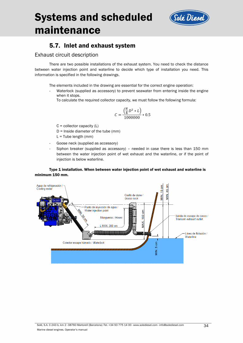
5.7. Inlet and exhaust system
Exhaust circuit description
There are two possible installations of the exhaust system. You need to check the distance
between water injection point and waterline to decide which type of installation you need. This
information is specified in the following drawings.
The elements included in the drawing are essential for the correct engine operation:
- Waterlock (supplied as accessory) to prevent seawater from entering inside the engine
when it stops.
To calculate the required collector capacity, we must follow the following formula:
𝐶 = (
𝜋4
𝐷2 ∗ 𝐿)
1000000∗ 0.5
C = collector capacity (L)
D = Inside diameter of the tube (mm)
L = Tube length (mm)
- Goose neck (supplied as accessory)
- Siphon breaker (supplied as accessory) – needed in case there is less than 150 mm
between the water injection point of wet exhaust and the waterline, or if the point of
injection is below waterline.
Type 1 installation. When between water injection point of wet exhaust and waterline is
minimum 150 mm.
Solé, S.A. C-243 b, km 2 · 08760 Martorell (Barcelona) ·Tel. +34 93 775 14 00 · www.solediesel.com · [email protected] 35 Marine diesel engines. Operator’s manual
Systems and scheduled
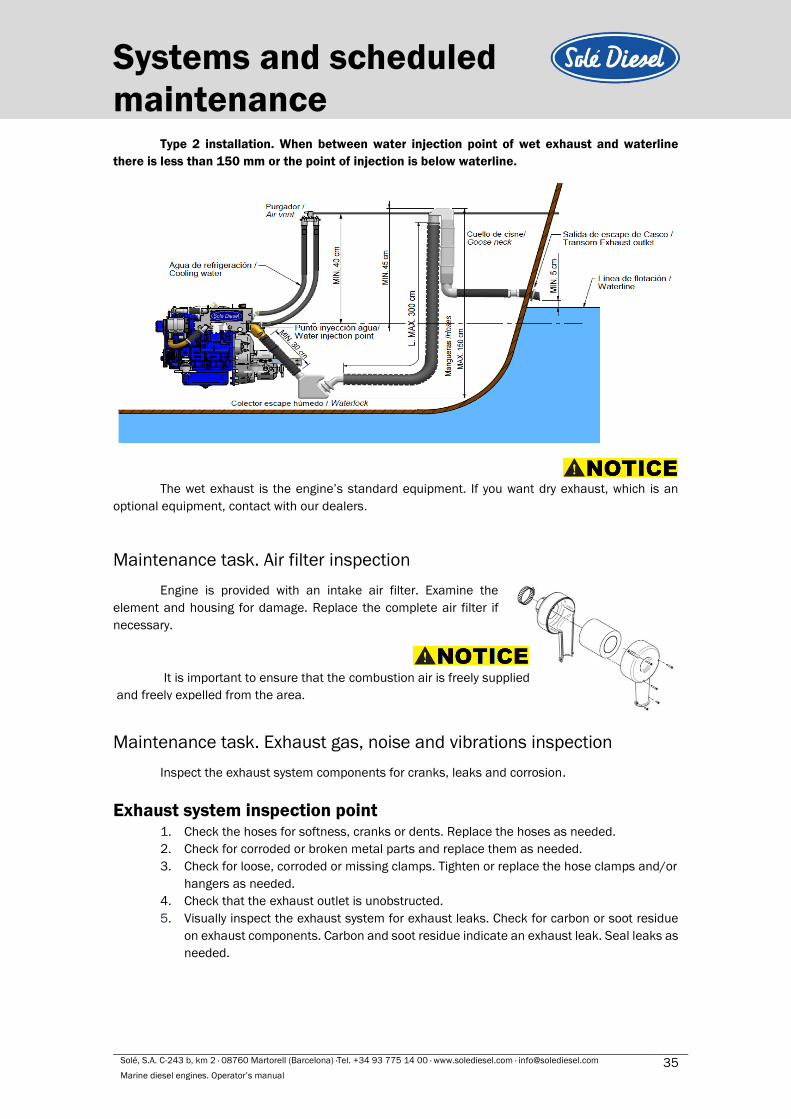
maintenance Type 2 installation. When between water injection point of wet exhaust and waterline
there is less than 150 mm or the point of injection is below waterline.
The wet exhaust is the engine’s standard equipment. If you want dry exhaust, which is an
optional equipment, contact with our dealers.
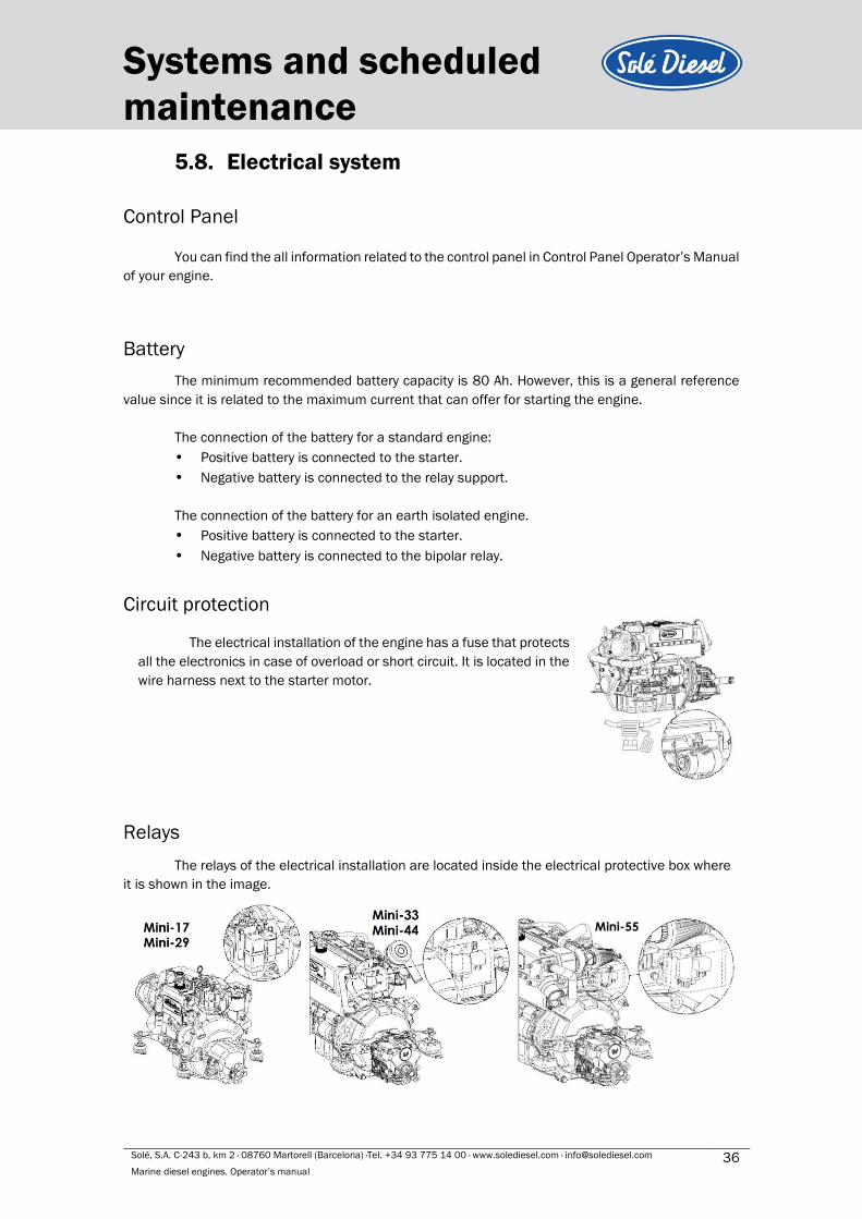
Maintenance task. Air filter inspection
Engine is provided with an intake air filter. Examine the
element and housing for damage. Replace the complete air filter if
necessary.
Maintenance task. Exhaust gas, noise and vibrations inspection
Inspect the exhaust system components for cranks, leaks and corrosion.
Exhaust system inspection point
1. Check the hoses for softness, cranks or dents. Replace the hoses as needed.
2. Check for corroded or broken metal parts and replace them as needed.
3. Check for loose, corroded or missing clamps. Tighten or replace the hose clamps and/or
hangers as needed.
4. Check that the exhaust outlet is unobstructed.
5. Visually inspect the exhaust system for exhaust leaks. Check for carbon or soot residue
on exhaust components. Carbon and soot residue indicate an exhaust leak. Seal leaks as
needed.
It is important to ensure that the combustion air is freely supplied
and freely expelled from the area.
Solé, S.A. C-243 b, km 2 · 08760 Martorell (Barcelona) ·Tel. +34 93 775 14 00 · www.solediesel.com · [email protected] 36 Marine diesel engines. Operator’s manual
Systems and scheduled
maintenance
5.8. Electrical system
Control Panel
You can find the all information related to the control panel in Control Panel Operator’s Manual
of your engine.
Battery
The minimum recommended battery capacity is 80 Ah. However, this is a general reference
value since it is related to the maximum current that can offer for starting the engine.
The connection of the battery for a standard engine:
• Positive battery is connected to the starter.
• Negative battery is connected to the relay support.
The connection of the battery for an earth isolated engine.
• Positive battery is connected to the starter.
• Negative battery is connected to the bipolar relay.
Circuit protection
Relays
The relays of the electrical installation are located inside the electrical protective box where
it is shown in the image.
The electrical installation of the engine has a fuse that protects
all the electronics in case of overload or short circuit. It is located in the
wire harness next to the starter motor.

Solé, S.A. C-243 b, km 2 · 08760 Martorell (Barcelona) ·Tel. +34 93 775 14 00 · www.solediesel.com · [email protected] 37 Marine diesel engines. Operator’s manual
Systems and scheduled
maintenance The earth isolated motors have bipolar relays, in the images can see the position.
Maintenance task. Incandescent glow plug inspection
1. Loosen nuts, and then remove connection plate and glow plug.
2. If the glow plug glows red when the positive (+) wire is connected to the portion A with the
portion B grounded, the plug can be used.
Maintenance task. Starter motor inspection
STARTER MOTOR:
1. Check if there is any impurity in pinion teeth.
2. Make sure that the pinion shaft turns freely when turned in the
direction of driving (clockwise) and it is locked when turned in the
opposite direction. If not, replace the overrunning clutch.
Maintenance task. Alternator belt tension inspection
Push the belt inward with thumb pressure exerted midway between the
pulleys, as shown, to check the belt tension (deflection). If the tension is
incorrect, loosen the adjusting bracket bolt and mounting bolt, and move the
alternator in or out.
Rated Voltage - Current 12 V 9,7 – 10,5 A
Element Assembly Standard
V-belt deflection 10-12 mm
1
Solé, S.A. C-243 b, km 2 · 08760 Martorell (Barcelona) ·Tel. +34 93 775 14 00 · www.solediesel.com · [email protected] 38 Marine diesel engines. Operator’s manual
Systems and scheduled
maintenance
An excessive tension may cause a quick wear of the belt and alternator bearings. Otherwise,
if the belt is excessively loose or has oil and insufficient load, it can cause the belt to skid.
Never adjust the belt tension with engine running or battery connected.
Maintenance task. Battery level
Battery requires a very careful handling and frequent checking. Proceed as shown below:
1. Keep battery dry and cleaned.
2. Check terminal cleanliness regularly. If dust is settled, terminals should be loosened,
cleaned and smeared with a neutral grease layer.
3. Metal objects must not be placed over the battery.
4. Add distilled water if the level is out of range
Solé, S.A. C-243 b, km 2 · 08760 Martorell (Barcelona) ·Tel. +34 93 775 14 00 · www.solediesel.com · [email protected] 39 Marine diesel engines. Operator’s manual
Troubleshooting
Section 6 - Troubleshooting
If a fault occurs in the engine, proceed as follows:
❖ Within the period of warranty
• Contact to Solé Diesel Official Service. See SOLÉ DIESEL WARRANTY
❖ Outside the period of warranty
• Contact to Solé Diesel Official Service. See SOLÉ DIESEL WARRANTY.
• Stop the engine, determine the cause and repair it before continuing driving the motor.
Solé, S.A. C-243 b, km 2 · 08760 Martorell (Barcelona) ·Tel. +34 93 775 14 00 · www.solediesel.com · [email protected] 40 Marine diesel engines. Operator’s manual
Troubleshooting
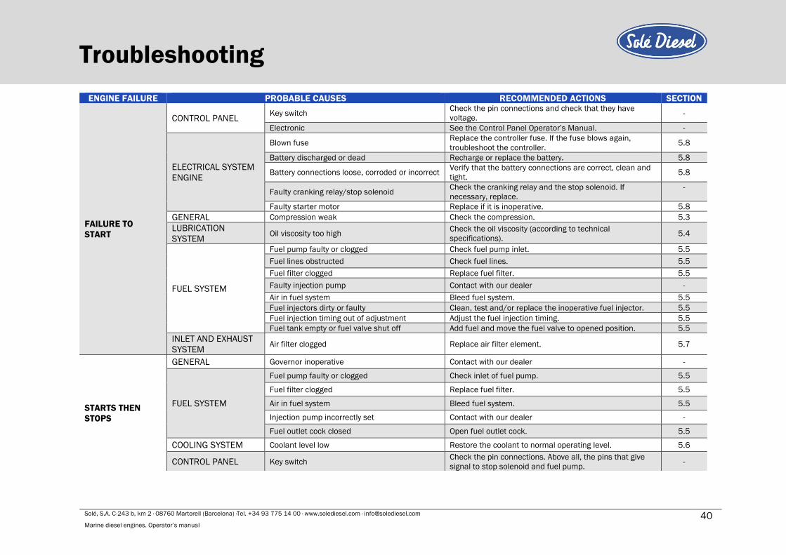
ENGINE FAILURE PROBABLE CAUSES RECOMMENDED ACTIONS SECTION
FAILURE TO
START
CONTROL PANEL Key switch
Check the pin connections and check that they have
voltage. -
Electronic See the Control Panel Operator’s Manual. -
ELECTRICAL SYSTEM
ENGINE
Blown fuse Replace the controller fuse. If the fuse blows again,
troubleshoot the controller. 5.8
Battery discharged or dead Recharge or replace the battery. 5.8
Battery connections loose, corroded or incorrect Verify that the battery connections are correct, clean and
tight. 5.8
Faulty cranking relay/stop solenoid Check the cranking relay and the stop solenoid. If
necessary, replace.
-
Faulty starter motor Replace if it is inoperative. 5.8
GENERAL Compression weak Check the compression. 5.3
LUBRICATION
SYSTEM Oil viscosity too high
Check the oil viscosity (according to technical
specifications). 5.4
FUEL SYSTEM
Fuel pump faulty or clogged Check fuel pump inlet. 5.5
Fuel lines obstructed Check fuel lines. 5.5
Fuel filter clogged Replace fuel filter. 5.5
Faulty injection pump Contact with our dealer -
Air in fuel system Bleed fuel system. 5.5
Fuel injectors dirty or faulty Clean, test and/or replace the inoperative fuel injector. 5.5
Fuel injection timing out of adjustment Adjust the fuel injection timing. 5.5
Fuel tank empty or fuel valve shut off Add fuel and move the fuel valve to opened position. 5.5
INLET AND EXHAUST
SYSTEM Air filter clogged Replace air filter element. 5.7
STARTS THEN
STOPS
GENERAL Governor inoperative Contact with our dealer -
FUEL SYSTEM
Fuel pump faulty or clogged Check inlet of fuel pump. 5.5
Fuel filter clogged Replace fuel filter. 5.5
Air in fuel system Bleed fuel system. 5.5
Injection pump incorrectly set Contact with our dealer -
Fuel outlet cock closed Open fuel outlet cock. 5.5
COOLING SYSTEM Coolant level low Restore the coolant to normal operating level. 5.6
CONTROL PANEL Key switch Check the pin connections. Above all, the pins that give
signal to stop solenoid and fuel pump. -
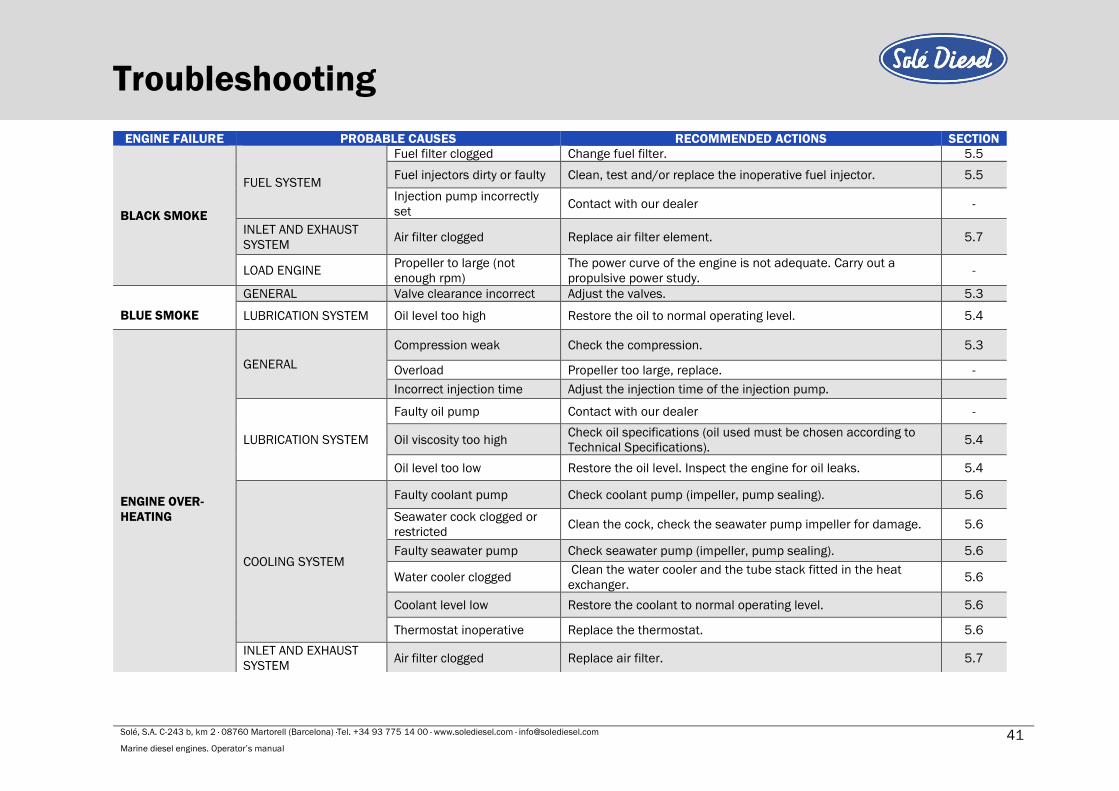
Solé, S.A. C-243 b, km 2 · 08760 Martorell (Barcelona) ·Tel. +34 93 775 14 00 · www.solediesel.com · [email protected] 41 Marine diesel engines. Operator’s manual
Troubleshooting
ENGINE FAILURE PROBABLE CAUSES RECOMMENDED ACTIONS SECTION
BLACK SMOKE
FUEL SYSTEM
Fuel filter clogged Change fuel filter. 5.5
Fuel injectors dirty or faulty Clean, test and/or replace the inoperative fuel injector. 5.5
Injection pump incorrectly
set Contact with our dealer -
INLET AND EXHAUST
SYSTEM Air filter clogged Replace air filter element. 5.7
LOAD ENGINE Propeller to large (not
enough rpm)
The power curve of the engine is not adequate. Carry out a
propulsive power study. -
BLUE SMOKE
GENERAL Valve clearance incorrect Adjust the valves. 5.3
LUBRICATION SYSTEM Oil level too high Restore the oil to normal operating level. 5.4
ENGINE OVER-
HEATING
GENERAL
Compression weak Check the compression. 5.3
Overload Propeller too large, replace. -
Incorrect injection time Adjust the injection time of the injection pump.
LUBRICATION SYSTEM
Faulty oil pump Contact with our dealer -
Oil viscosity too high Check oil specifications (oil used must be chosen according to
Technical Specifications). 5.4
Oil level too low Restore the oil level. Inspect the engine for oil leaks. 5.4
COOLING SYSTEM
Faulty coolant pump Check coolant pump (impeller, pump sealing). 5.6
Seawater cock clogged or
restricted Clean the cock, check the seawater pump impeller for damage. 5.6
Faulty seawater pump Check seawater pump (impeller, pump sealing). 5.6
Water cooler clogged Clean the water cooler and the tube stack fitted in the heat
exchanger. 5.6
Coolant level low Restore the coolant to normal operating level. 5.6
Thermostat inoperative Replace the thermostat. 5.6
INLET AND EXHAUST
SYSTEM Air filter clogged Replace air filter. 5.7
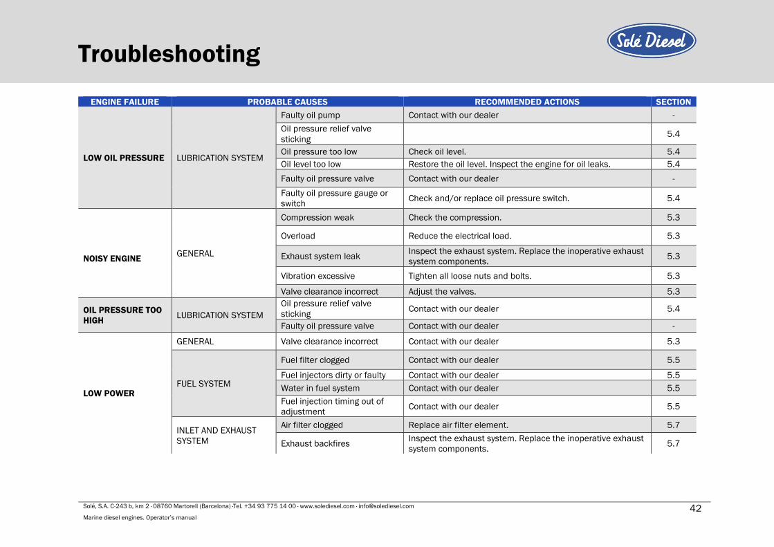
Solé, S.A. C-243 b, km 2 · 08760 Martorell (Barcelona) ·Tel. +34 93 775 14 00 · www.solediesel.com · [email protected] 42 Marine diesel engines. Operator’s manual
Troubleshooting ENGINE FAILURE PROBABLE CAUSES RECOMMENDED ACTIONS SECTION
LOW OIL PRESSURE LUBRICATION SYSTEM
Faulty oil pump Contact with our dealer -
Oil pressure relief valve
sticking 5.4
Oil pressure too low Check oil level. 5.4
Oil level too low Restore the oil level. Inspect the engine for oil leaks. 5.4
Faulty oil pressure valve Contact with our dealer -
Faulty oil pressure gauge or
switch Check and/or replace oil pressure switch. 5.4
NOISY ENGINE GENERAL
Compression weak Check the compression. 5.3
Overload Reduce the electrical load. 5.3
Exhaust system leak Inspect the exhaust system. Replace the inoperative exhaust
system components. 5.3
Vibration excessive Tighten all loose nuts and bolts. 5.3
Valve clearance incorrect Adjust the valves. 5.3
OIL PRESSURE TOO
HIGH LUBRICATION SYSTEM
Oil pressure relief valve
sticking Contact with our dealer 5.4
Faulty oil pressure valve Contact with our dealer -
LOW POWER
GENERAL Valve clearance incorrect Contact with our dealer 5.3
FUEL SYSTEM
Fuel filter clogged Contact with our dealer 5.5
Fuel injectors dirty or faulty Contact with our dealer 5.5
Water in fuel system Contact with our dealer 5.5
Fuel injection timing out of
adjustment Contact with our dealer 5.5
INLET AND EXHAUST
SYSTEM
Air filter clogged Replace air filter element. 5.7
Exhaust backfires Inspect the exhaust system. Replace the inoperative exhaust
system components. 5.7
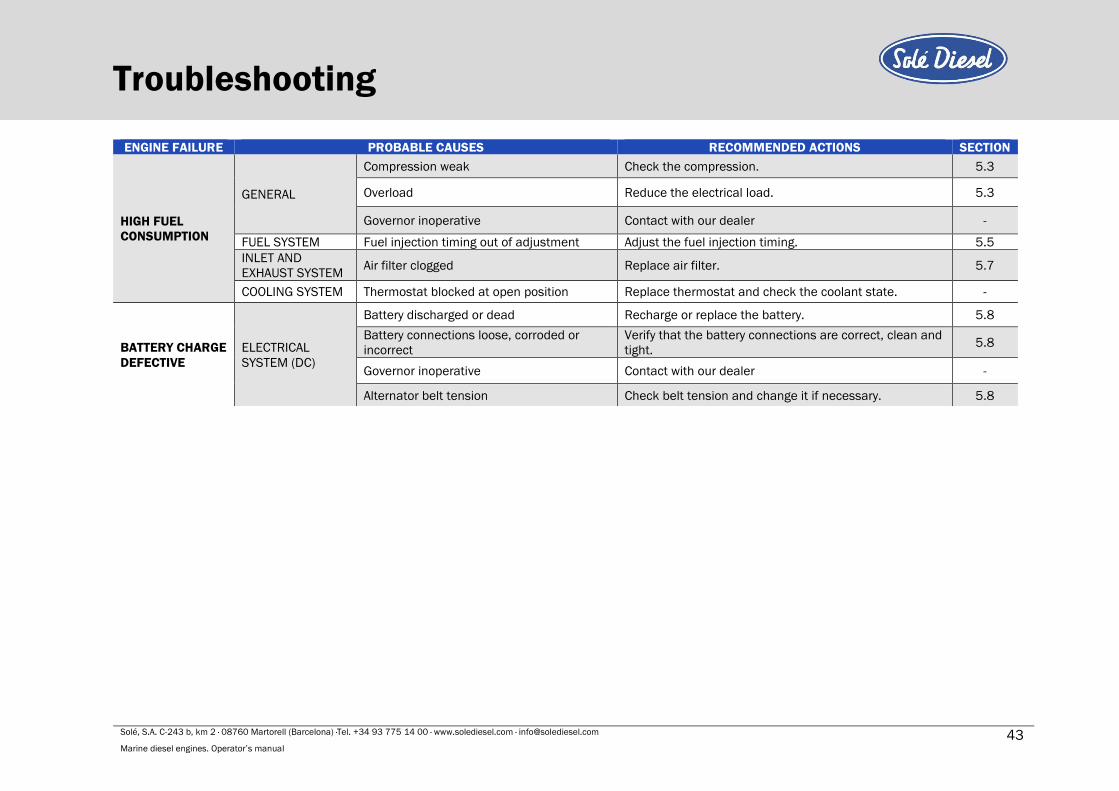
Solé, S.A. C-243 b, km 2 · 08760 Martorell (Barcelona) ·Tel. +34 93 775 14 00 · www.solediesel.com · [email protected] 43 Marine diesel engines. Operator’s manual
Troubleshooting
ENGINE FAILURE PROBABLE CAUSES RECOMMENDED ACTIONS SECTION
HIGH FUEL
CONSUMPTION
GENERAL
Compression weak Check the compression. 5.3
Overload Reduce the electrical load. 5.3
Governor inoperative Contact with our dealer -
FUEL SYSTEM Fuel injection timing out of adjustment Adjust the fuel injection timing. 5.5
INLET AND
EXHAUST SYSTEM Air filter clogged Replace air filter. 5.7
COOLING SYSTEM Thermostat blocked at open position Replace thermostat and check the coolant state. -
BATTERY CHARGE
DEFECTIVE
ELECTRICAL
SYSTEM (DC)
Battery discharged or dead Recharge or replace the battery. 5.8
Battery connections loose, corroded or
incorrect
Verify that the battery connections are correct, clean and
tight. 5.8
Governor inoperative Contact with our dealer -
Alternator belt tension Check belt tension and change it if necessary. 5.8

Technical specifications Section 7 - Technical specifications
MINI-17 MINI-29
DIESEL ENGINE
Ge
ne
ral
sp
ec
ific
ati
on
s
Type 4 cycle water-cooled, diesel cycle
Direction of rotation Anti-clockwise rotation as viewed from flywheel side
No. of cylinders - arrangement 2 in line 3 in line
Allowable Exhaust Back Pressure (kPa) Max. 6,57
Timing Pushrod and rocker arm with gear driven camshaft in
crankcase
Bore (mm) 76 76
Stroke (mm) 70 70
Total displacement (c.c.) 635 952
Compression ratio 23:1 22:1
Ignition sequence 1-2 1-3-2
Fuel injection timing APMS 17º APMS 19º
Injection pressure (kPa) 13,73 MPa (140 kg/cm2)
Inlet and exhaust valve clearance -
cold engine (mm) 0,25
Power (kW / HP) 11,8 / 16,05 20,0 / 27,20
RPM (rpm) 3600
Starting system Electric starting
Starting aid Glow plug
Lu
bri
ca
tio
n s
yste
m
System description Forced circulation by gear pump
Oil specifications Use oil with 15W40 viscosity and no less than ACEA
E5/E3 or API CH-4/SJ quality
Oil pump Gear type
Oil circuit capacity (l) 2,8 4,0
Lubrication oil pressure – nominal
speed (MPa) 0,29 (3 kgf/cm2) (2,9bar)
Min oil pressure - hot engine (MPa) 0,39 (4 kgf/cm2) (3,9bar)
Min oil pressure at idle speed (MPa) 0,098 (0,5 kg/cm2) (0,98 bar)
Oil temperature – nominal speed (ºC) 60 - 98
Maximum temperature of gearbox oil
(ºC) 95
Fu
el
syste
m System description Electric fuel pump and mechanic injection pump
Fuel specifications Diesel fuel ASTM diesel No.2-D
Fuel injection pump In line type
Fuel injection nozzle Throttle type

Solé, S.A. C-243 b, km 2 · 08760 Martorell (Barcelona) ·Tel. +34 93 775 14 00 · www.solediesel.com · [email protected] 45 Marine diesel engines. Operator’s manual
Technical specifications
1 For each curve of 90º of the installation, must increase 10 mm (for lengths superior to 3 m).
² Read the specific gearbox manual delivered together with the motor.
MINI-17 MINI-29
DIESEL ENGINE C
oo
lin
g s
yste
m
System description
Coolant circulation controlled by centrifugal pump with
thermostatic control and heat exchanger. Cooled
exhaust manifold.
Coolant specifications SOLÉ DIESEL50%
Coolant pump Centrifugal type
Sea water pump Flexible impeller type
Coolant circuit capacity (l) 2,7 3,0
Thermostat valve Start opening + 71ºC
End opnening + 85ºC
Coolant temperature – nominal speed
(ºC) 70 - 85
Inle
t a
nd
Exh
au
st
Syste
m Air supply Air cleaning by means of a dry-type air filter
Exhaust System
Air supply
Cooled exhaust manifold
Dry exhaust manifold (optional equipment)
Air cleaning by means of a dry-type air filter
Ele
ctr
ica
l
Sys
tem
Voltage – Polarity (V) 12V DC
Alternator DC (A) 75 75
Starter motor (kW) 1,2 1,2
Stop solenoid ETS
Insta
lla
tio
n
Ø Int. Hose, sea water inlet (mm) 20
Ø Int. Hose, diesel fuel inlet (mm) 8
Ø Int. Hose, exhaust outlet1 (mm) 40 50
Air admission displacement -max. rpm
(m3/h) 1 1,5
Minimum battery capacity (Ah) 45 (12 V) 60 (12 V)
Length of battery wire (m) ≤ 1,5
Minimal section of battery wire (mm2) 60
Oil
ca
pa
cit
y in
th
e i
nve
rte
r
(Lit
er)
.²
TMC 40 0.2 (ATF)
TMC 40P 0.2 (ATF)
SP60 2.8 (ATF)
TMC 60A 0.6 (ATF)
TMC 60P 0.65 (ATF)
TM-345 1.6 (SAE 15W40)
1.6 (SAE 15W40) TM-345A
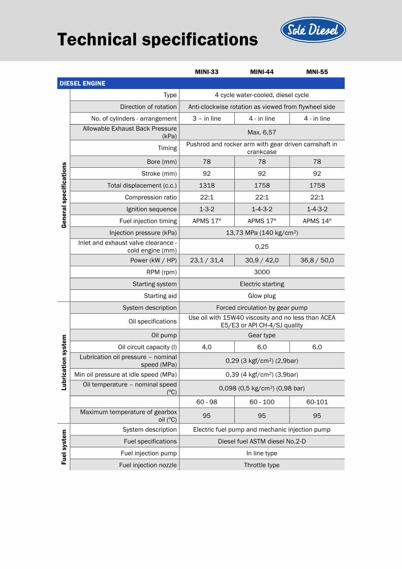
Technical specifications MINI-33 MINI-44 MNI-55
DIESEL ENGINE
Ge
ne
ral
sp
ec
ific
ati
on
s
Type 4 cycle water-cooled, diesel cycle
Direction of rotation Anti-clockwise rotation as viewed from flywheel side
No. of cylinders - arrangement 3 – in line 4 - in line 4 - in line
Allowable Exhaust Back Pressure
(kPa) Max. 6,57
Timing Pushrod and rocker arm with gear driven camshaft in
crankcase
Bore (mm) 78 78 78
Stroke (mm) 92 92 92
Total displacement (c.c.) 1318 1758 1758
Compression ratio 22:1 22:1 22:1
Ignition sequence 1-3-2 1-4-3-2 1-4-3-2
Fuel injection timing APMS 17º APMS 17º APMS 14º
Injection pressure (kPa) 13,73 MPa (140 kg/cm2)
Inlet and exhaust valve clearance -
cold engine (mm) 0,25
Power (kW / HP) 23,1 / 31,4 30,9 / 42,0 36,8 / 50,0
RPM (rpm) 3000
Starting system Electric starting
Starting aid Glow plug
Lu
bri
ca
tio
n s
yste
m
System description Forced circulation by gear pump
Oil specifications Use oil with 15W40 viscosity and no less than ACEA
E5/E3 or API CH-4/SJ quality
Oil pump Gear type
Oil circuit capacity (l) 4,0 6,0 6,0
Lubrication oil pressure – nominal
speed (MPa) 0,29 (3 kgf/cm2) (2,9bar)
Min oil pressure at idle speed (MPa) 0,39 (4 kgf/cm2) (3,9bar)
Oil temperature – nominal speed
(ºC) 0,098 (0,5 kg/cm2) (0,98 bar)
60 - 98 60 - 100 60-101
Maximum temperature of gearbox
oil (ºC) 95 95 95
Fu
el
syste
m System description Electric fuel pump and mechanic injection pump
Fuel specifications Diesel fuel ASTM diesel No.2-D
Fuel injection pump In line type
Fuel injection nozzle Throttle type
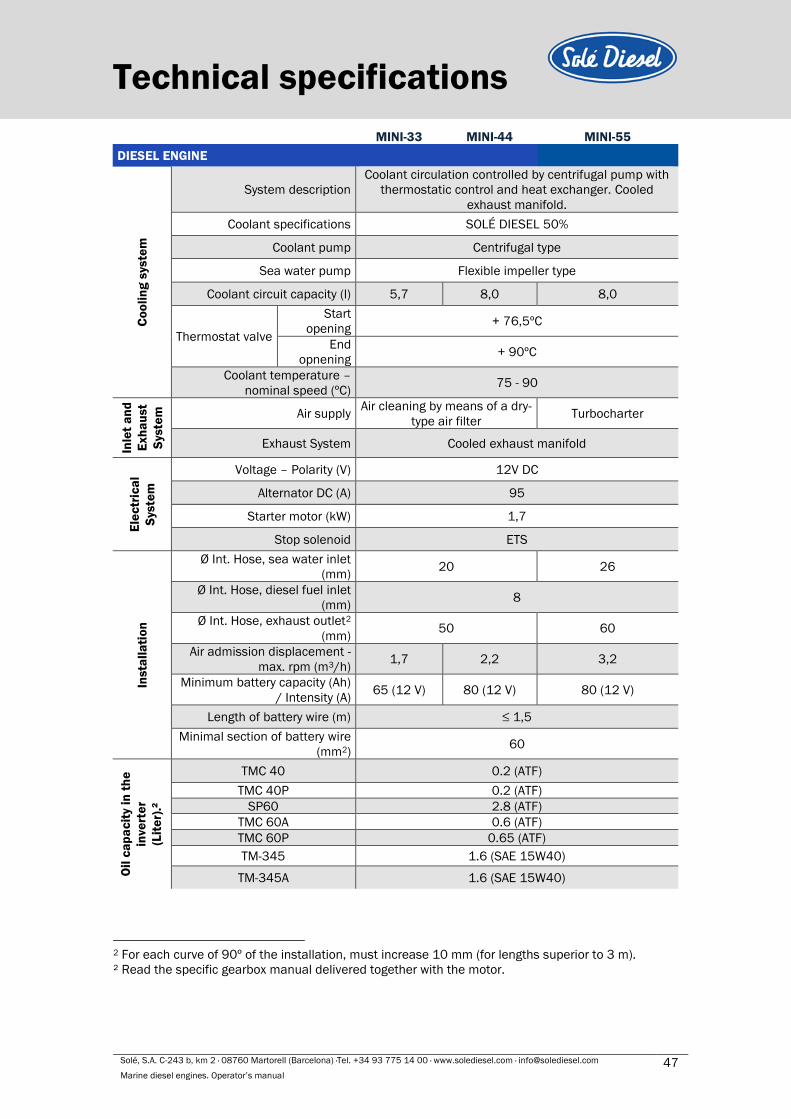
Solé, S.A. C-243 b, km 2 · 08760 Martorell (Barcelona) ·Tel. +34 93 775 14 00 · www.solediesel.com · [email protected] 47 Marine diesel engines. Operator’s manual
Technical specifications
2 For each curve of 90º of the installation, must increase 10 mm (for lengths superior to 3 m).
² Read the specific gearbox manual delivered together with the motor.
MINI-33 MINI-44 MINI-55
DIESEL ENGINE
Co
oli
ng
sys
tem
System description
Coolant circulation controlled by centrifugal pump with
thermostatic control and heat exchanger. Cooled
exhaust manifold.
Coolant specifications SOLÉ DIESEL 50%
Coolant pump Centrifugal type
Sea water pump Flexible impeller type
Coolant circuit capacity (l) 5,7 8,0 8,0
Thermostat valve
Start
opening + 76,5ºC
End
opnening + 90ºC
Coolant temperature –
nominal speed (ºC) 75 - 90
Inle
t a
nd
Exh
au
st
Syste
m
Air supply Air cleaning by means of a dry-
type air filter Turbocharter
Exhaust System Cooled exhaust manifold
Ele
ctr
ica
l
Sys
tem
Voltage – Polarity (V) 12V DC
Alternator DC (A) 95
Starter motor (kW) 1,7
Stop solenoid ETS
Insta
lla
tio
n
Ø Int. Hose, sea water inlet
(mm) 20 26
Ø Int. Hose, diesel fuel inlet
(mm) 8
Ø Int. Hose, exhaust outlet2
(mm) 50 60
Air admission displacement -
max. rpm (m3/h) 1,7 2,2 3,2
Minimum battery capacity (Ah)
/ Intensity (A) 65 (12 V) 80 (12 V) 80 (12 V)
Length of battery wire (m) ≤ 1,5
Minimal section of battery wire
(mm2) 60
Oil
ca
pa
cit
y in
th
e
inve
rte
r
(Lit
er)
.²
TMC 40 0.2 (ATF)
TMC 40P 0.2 (ATF)
SP60 2.8 (ATF)
TMC 60A 0.6 (ATF)
TMC 60P 0.65 (ATF)
TM-345 1.6 (SAE 15W40)
TM-345A 1.6 (SAE 15W40)

Tightening torques Section 8 – Tightening torques
Important nuts and screws:

Solé, S.A. C-243 b, km 2 · 08760 Martorell (Barcelona) ·Tel. +34 93 775 14 00 · www.solediesel.com · [email protected] 49 Marine diesel engines. Operator’s manual
Tightening torques

Wiring diagrams Section 9 – Wiring diagrams

DIBUJADO VERIFICADO FECHA CREACIÓN ÚLTIMA REVISIÓN
SOLÉ, S.A.RUBEN D.D. ROMARTÍNEZ 16/03/2017
PÁGINA
1 de 1E1380E02P_SVT
MINI-17 / MINI-29 / MINI-33 / MINI-44 / MINI-55
12V / 24VLEYENDA / LEGEND:
- N.S.: NO SUMINISTRADO / NOT SUPPLIED
- OPT.: OPCIONAL / OPTIONAL
MODELO MOTOR / ENGINE MODEL:
VOLTAGE MOTOR / ENGINE VOLTAGE:
C1.2
N.S.
N.S.
M
GD
B
W
C2.2
C2.4
C1.1
C1.4
C2.3
C2.1
C2.5
C1.5
C1.3
30
8586 87
BOMBA DE ALIMENTACIÓN DE CUMBUSTIBLE/FUEL FEED PUMP
C2.6
C1.6
10 A
86
30
85
87
85
86
CONECTOR 1: C1 /CONNECTOR 1: C1
TRANSMISOR DE PRESIÓN / PRESSURE SENSOR
TRANSMISOR DE TEMPERATURA / TEMPERATURE SENSOR
MANOCONTACTO / PRESSURE SWITCH
TERMOCONTACTO / TEMPERATURE SWITCH
ETS SOLENOIDE DE PARO / ETS STOP SOLENOID
PRECALENTAMIENTO / PREHEATING
MOTOR DE ARRANQUE / STARTER
ALTERNADOR / ALTERNATOR
Violeta / Purple
Negro / Black
Rojo / Red
Rosa / Pink
Rojo-Blanco / Red-White
Verde-Blanco / Green-White
Amarillo / Yellow
Blanco / White
Azul / Blue
Gris / Grey
Marrón / Brown
Verde / Green
30 8586 87
ARRANQUE / CRANKING
DETALLE RELE BUJIAS PRECALENTAMIENTO / PREHEATING RELAY
CONECTOR 2: C2 /CONNECTOR 2: C2
DETALLE RELE DE ARRANQUE /STARTER RELAY
6 5 4 3 2 1 1 2 3 4 5 6
30
8786
85

DIBUJADO VERIFICADO FECHA CREACIÓN ÚLTIMA REVISIÓN
SOLÉ, S.A.RUBEN D.D. ROMARTÍNEZ 30/03/2017
PÁGINA
1 de 1E1380B02P_SVT
MINI-17 / MINI-29 / MINI-33 / MINI-44 / MINI-55 LIBRE MASA / ISOLATED
12V / 24VLEYENDA / LEGEND:
- N.S.: NO SUMINISTRADO / NOT SUPPLIED
- OPT.: OPCIONAL / OPTIONAL
MODELO MOTOR / ENGINE MODEL:
VOLTAGE MOTOR / ENGINE VOLTAGE:
- C.I.: CABLE INDEPENDIENTE / SEPARATE CABLE
86
30
85
87
30
87
85
86
CONECTOR 1: C1 /CONNECTOR 1: C1
DETALLE RELÉ BUJIAS PRECALENTAMIENTO / PREHEATING RELAY
CONECTOR 2: C2 /CONNECTOR 2: C2
DETALLE RELÉS DE ARRANQUE /STARTER RELAY
6 5 4 3 2 1 1 2 3 4 5 6
C1.2
C2.2
C2.4
C1.1
C1.4
C2.1
C2.5
C1.5
C1.3
C2.6
C1.6
N.S.
N.S.
M
GD
B
W
Violeta/Purple
Negro/Black
Rojo/Red
Rosa/Pink
Rojo-Blanco/Red-White
Verde/Green
Verde-Blanco/Green-White
Amarillo/Yellow
Blanco/White
Azul/Blue
Gris/Grey
Marrón/Brown
ARRANQUE /CRANKING
RELÉ DESCONEXIÓN DE TIERRA /EARTH DISCONNECTING RELAY
Diodos 2,5 A
C.I.
TRANSMISOR DE PRESIÓN / PRESSURE SENSOR
TRANSMISOR DE TEMPERATURA / TEMPERATURE SENSOR
MANOCONTACTO / PRESSURE SWITCH
TERMOOCONTACTO / TEMPERATURE SWITCH
ETS SOLENOIDE DE PARO / ETS STOP SOLENOID
10 A
MOTOR DE ARRANQUE / STARTER
30 8586 87
30
8586
87 86 85
3087
ALTERNADOR / ALTERNATOR
PRECALENTAMIENTO / PREHEATING BOMBA DE ALIMENTACIÓN DE CUMBUSTIBLE/FUEL FEED PUMP
85(-)86(+)
87
30
DETALLE RELÉ AISLAMIENTO / ISOLATING RELAY
C2.3
86
85
Solé, S.A. C-243 b, km 2 · 08760 Martorell (Barcelona) ·Tel. +34 93 775 14 00 · www.solediesel.com · [email protected] 53 Marine diesel engines. Operator’s manual
Overall dimensions Section 10 – Overall dimensions

DIBUJADO VERIFICADO GRADO PRECISIÓN FECHA CREACIÓN ÚLTIMA REVISIÓN
MATERIAL TRATAMIENTO ESCALAPRESENTACIÓNACABADO
SOLÉ, S.A.
MOTOR MINI-17 v6 INV. TMC-40 2,00:1MINI-17 v6 ENGINE TMC-40 2.00:1 GBOX.
JOSE ---
13830263.6
./.
04/09/2017
67.5
100
259
DATOS TÉCNICOS / TECHNICAL DATA
Manguera entrada agua salada / Sea water hose intake: Ø20mm Manguera entrada combustible / Fuel hose intake: Ø8mm Manguera retorno combustible / Diesel Fuel return hose: Ø5mm
Pletina InversorGbox flange
63.5
H8
O
3
82.5
O
102
O10
4 Taladros a Ø10.5
40O
85.53
612.5
553.5
210
210
420
372.5
9376
9.5OO64
Especificaciones del producto pueden ser modificadas sin previo aviso(product specifications are subject to change without notice)
210 210
Max
. 72
Min
. 58
228.14 229.4
174.
1136
8
542.
11
189.5
484
457.54
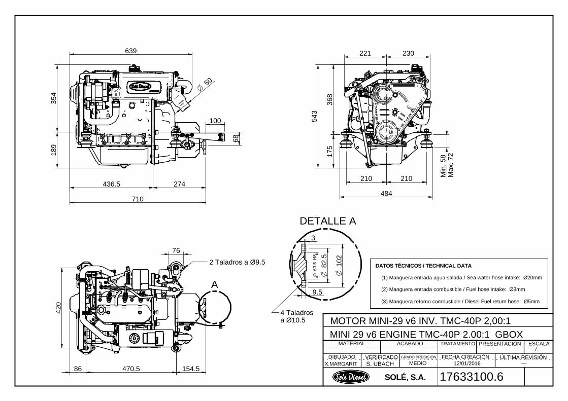
DIBUJADO VERIFICADO GRADO PRECISIÓN FECHA CREACIÓN ÚLTIMA REVISIÓN
MATERIAL TRATAMIENTO ESCALAPRESENTACIÓNACABADO
SOLÉ, S.A.
MOTOR MINI-29 v6 INV. TMC-40P 2,00:1MINI 29 v6 ENGINE TMC-40P 2.00:1 GBOX
X.MARGARIT S. UBACH MEDIO ---
17633100.6
./.
12/01/2016
DATOS TÉCNICOS / TECHNICAL DATA
(1) Manguera entrada agua salada / Sea water hose intake: Ø20mm
(2) Manguera entrada combustible / Fuel hose intake: Ø8mm
(3) Manguera retorno combustible / Diesel Fuel return hose: Ø5mm
354
189
639
50O
221 230
368
Min
. 58
Max
. 72
543
210 210
484
420
154.586
175
436.5 274
710
68
470.5
76
2 Taladros a Ø9.5
4 Taladros a Ø10.5
100
A
DETALLE A
63.5
H8
O
82.5
O
102
O
9.5
3
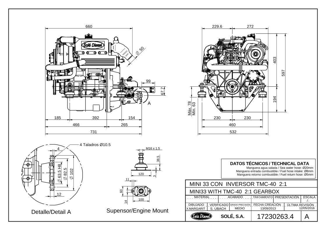
DIBUJADO VERIFICADO GRADO PRECISIÓN FECHA CREACIÓN ÚLTIMA REVISIÓN
MATERIAL TRATAMIENTO ESCALAPRESENTACIÓNACABADO
SOLÉ, S.A.
MINI 33 CON INVERSOR TMC-40 2:1MINI33 WITH TMC-40 2:1 GEARBOX
X.MARGARIT S. UBACH MEDIO 12/05/2016
17230263.4
./.
A13/09/2013
DATOS TÉCNICOS / TECHNICAL DATA Manguera agua salada / Sea water hose: Ø20mm
Manguera entrada combustible / Fuel hose intake: Ø8mm Manguera retorno combustible / Fuel return hose: Ø5mm
O 6
3.5
H8
4
O 8
2.5
O 1
02
12
4 Taladros Ø10.5
A
230230
460
532
194
403
597
272
185 392 154
466 265
731
67.7
50O
660
99
Máx
. 78
Mín
. 63
229.6
Detalle/Detail A
M16 x 1.5
60
338
.5
100
120
14
11
Supensor/Engine Mount

DIBUJADO VERIFICADO GRADO PRECISIÓN FECHA CREACIÓN ÚLTIMA REVISIÓN
MATERIAL TRATAMIENTO ESCALAPRESENTACIÓNACABADO
SOLÉ, S.A.
MOTOR MINI-44 v6 INV. TMC-60P 2,00:1MINI-44 v6 ENGINE TMC-60P 2.00:1 GBOX.
J.RODRÍGUEZ ---
17333483V6
./.
---01/06/2018
50O
230
230
460
480.5
110.5
184140
13
30
22
13
255.67 270.5
526.17
739.3
400.
8
DATOS TÉCNICOS (TECHNICAL DATA) Manguera agua salada (Sea water hose) : Ø20mm Manguera entrada combustible (Fuel hose, inlet): Ø8mm Manguera retorno combustible (Fuel Hose, outlet): Ø5mm
Especificaciones del producto pueden ser modificadas sin previo aviso(Product specifications are subject to change without notice)
Max
. 88
Min
. 74
75
O 6
3.5
H8
4
O 8
2.5
O 1
02
12
4x Ø10.5
Salida InversorOutput Gearbox
78.8
219.5
230.7130.5 100.2181.17 480.5
881.17
210.
66
611.
46
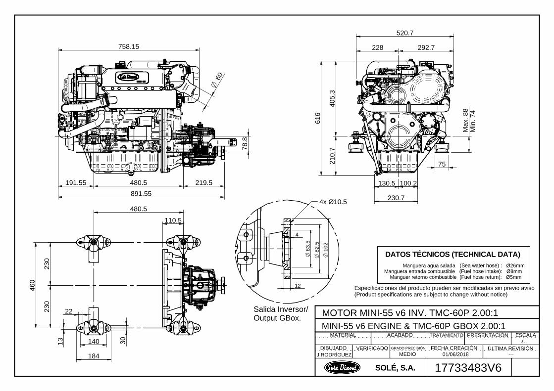
DIBUJADO VERIFICADO GRADO PRECISIÓN FECHA CREACIÓN ÚLTIMA REVISIÓN
MATERIAL TRATAMIENTO ESCALAPRESENTACIÓNACABADO
SOLÉ, S.A.
MOTOR MINI-55 v6 INV. TMC-60P 2.00:1MINI-55 v6 ENGINE & TMC-60P GBOX 2.00:1
J.RODRÍGUEZ MEDIO ---
17733483V6
./.
01/06/2018
DATOS TÉCNICOS (TECHNICAL DATA) Manguera agua salada (Sea water hose) : Ø26mm
Manguera entrada combustible (Fuel hose intake): Ø8mm Manguer retorno combustible (Fuel hose return): Ø5mm
Especificaciones del producto pueden ser modificadas sin previo aviso(Product specifications are subject to change without notice)
230
230
460
184
14013
22
30
60O
78.8
758.15
210.
740
5.3
616
228 292.7
520.7
Max
. 88
Min
. 74
480.5
110.5
100.2
891.55
O 6
3.5
4
O 8
2.5
O 1
02
12
4x Ø10.5
Salida Inversor/Output GBox.
230.7
130.5191.55 480.5 219.5
75
Solé, S.A. C-243 b, km 2 · 08760 Martorell (Barcelona) ·Tel. +34 93 775 14 00 · www.solediesel.com · [email protected] 59 Marine diesel engines. Operator’s manual
Instructions to Replace
and Remove Section 11 – Instructions to Replace and Remove
When you decide to replace the engine, please contact SOLÉ S.A.; will provide relevant
instructions regarding the laws in force at the time. When disposing of the whole or parts of this engine,
meets LAWS IN FORCE IN THE COUNTRY OF INSTALLATION.
For more information about the materials they are made of the individual components of the
engine, contact SOLÉ S.A.

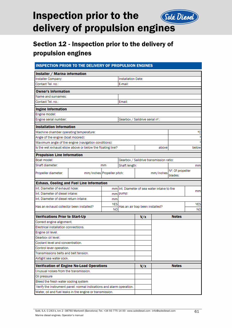
Solé, S.A. C-243 b, km 2 · 08760 Martorell (Barcelona) ·Tel. +34 93 775 14 00 · www.solediesel.com · [email protected] 61 Marine diesel engines. Operator’s manual
Inspection prior to the
delivery of propulsion engines
Section 12 - Inspection prior to the delivery of
propulsion engines
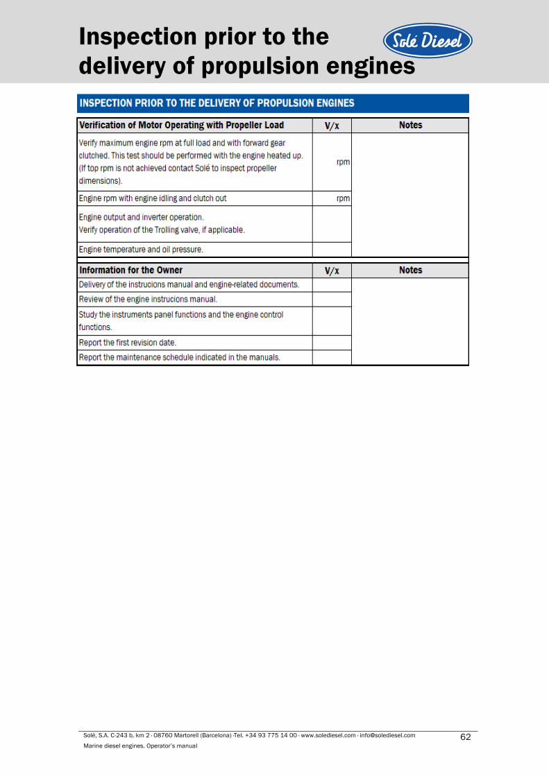
Solé, S.A. C-243 b, km 2 · 08760 Martorell (Barcelona) ·Tel. +34 93 775 14 00 · www.solediesel.com · [email protected] 62 Marine diesel engines. Operator’s manual
Inspection prior to the
delivery of propulsion engines
Solé, S.A. C-243 b, km 2 · 08760 Martorell (Barcelona) ·Tel. +34 93 775 14 00 · www.solediesel.com · [email protected] 63 Marine diesel engines. Operator’s manual
Declaration of conformity for
recreational Craft Propulsion Engines
Section 13 – Declaration of conformity for
recreational Craft Propulsion Engines
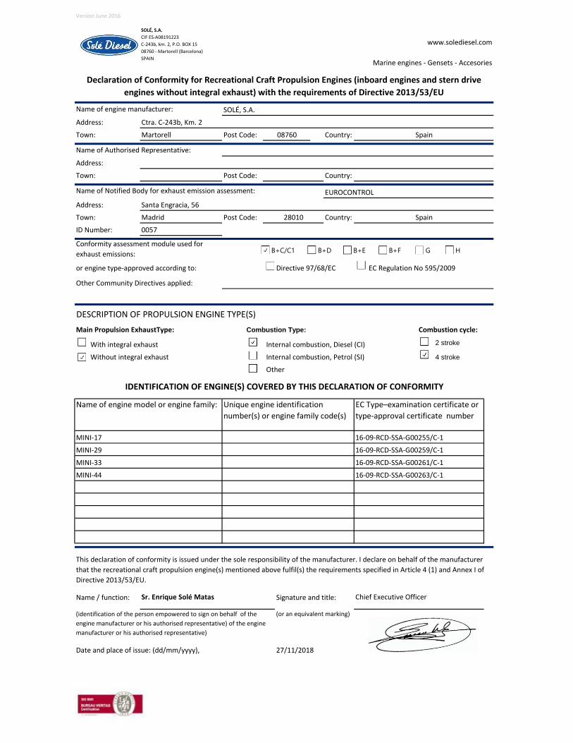
Version June 2016
0
Address:
Town: Martorell Post Code: Country:
Address:
Town: Post Code: Country:
Address:
Town: Madrid Post Code: Country:
ID Number: 0057
or engine type-approved according to: Directive 97/68/EC EC Regulation No 595/2009
Main Propulsion ExhaustType: Combustion cycle:
With integral exhaust Internal combustion, Diesel (CI) 2 stroke
Without integral exhaust Internal combustion, Petrol (SI) 4 stroke
Other
Name / function: Signature and title:
Name of engine model or engine family: EC Type–examination certificate or
type-approval certificate number
Unique engine identification
number(s) or engine family code(s)
MINI-17
Combustion Type:
27/11/2018Date and place of issue: (dd/mm/yyyy),
16-09-RCD-SSA-G00255/C-1
MINI-29 16-09-RCD-SSA-G00259/C-1
Sr. Enrique Solé Matas Chief Executive Officer
(identification of the person empowered to sign on behalf of the
engine manufacturer or his authorised representative) of the engine
manufacturer or his authorised representative)
(or an equivalent marking)
This declaration of conformity is issued under the sole responsibility of the manufacturer. I declare on behalf of the manufacturer
that the recreational craft propulsion engine(s) mentioned above fulfil(s) the requirements specified in Article 4 (1) and Annex I of
Directive 2013/53/EU.
MINI-33 16-09-RCD-SSA-G00261/C-1
Ctra. C-243b, Km. 2
IDENTIFICATION OF ENGINE(S) COVERED BY THIS DECLARATION OF CONFORMITY
DESCRIPTION OF PROPULSION ENGINE TYPE(S)
Other Community Directives applied:
08760 Spain
MINI-44 16-09-RCD-SSA-G00263/C-1
Name of Notified Body for exhaust emission assessment:
28010 Spain
Santa Engracia, 56
Conformity assessment module used for
exhaust emissions:
Name of engine manufacturer: SOLÉ, S.A.
Name of Authorised Representative:
EUROCONTROL
SOLÉ, S.A.
CIF ES-A08191223
C-243b, km. 2, P.O. BOX 15
08760 - Martorell (Barcelona)
SPAIN
www.solediesel.com
Marine engines - Gensets - Accesories
Declaration of Conformity for Recreational Craft Propulsion Engines (inboard engines and stern drive
engines without integral exhaust) with the requirements of Directive 2013/53/EU
B+C/C1 B+D B+E B+F G H
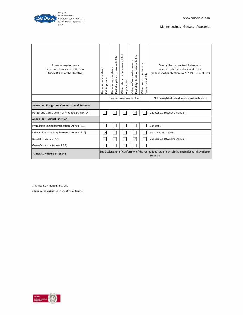
Durability (Annex I B.3)
Owner’s manual (Annex I B.4)
1. Annex I.C – Noise Emissions
2.Standards published in EU Official Journal
www.solediesel.com
Marine engines - Gensets - Accesories
Chapter 1.1 (Owner's Manual)
SOLÉ, S.A.
CIF ES-A08191223
C-243b, km. 2, P.O. BOX 15
08760 - Martorell (Barcelona)
SPAIN
Specify the harmonised 2 standards
or other reference documents used
(with year of publication like “EN ISO 8666:2002”)
Essential requirements
reference to relevant articles in
Annex IB & IC of the Directive)
All lines right of ticked boxes must be filled inTick only one box per line
Design and Construction of Products (Annex I A.)
Annex I.A - Design and Construction of ProductsH
arm
on
ised
sta
nd
ard
s
Full
Ap
plic
atio
n
Har
mo
nis
ed s
tan
dar
ds
Par
tial
ap
plic
atio
n, s
ee t
ech
. File
Oth
er r
efer
ence
do
cum
ents
1 F
ull
Ap
plic
atio
n
Oth
er r
efer
ence
do
cum
ents
Par
tial
Ap
plic
atio
n ,
see
tech
. File
Oth
er p
roo
f o
f co
nfo
rmit
y
See
tech
nic
al. F
ile
See Declaration of Conformity of the recreational craft in which the engine(s) has (have) been
installed Annex I.C – Noise Emissions
Exhaust Emission Requirements (Annex I B. 2)
Annex I.B – Exhaust Emissions
Propulsion Engine Identification (Annex I B.1) Chapter 1
EN ISO 8178-1:1996
Chapter 7.1 (Owner's Manual)

Version June 2016
0
Address:
Town: Martorell Post Code: Country:
Address:
Town: Post Code: Country:
Address:
Town: Bristol Post Code: Country:
ID Number: 1580
or engine type-approved according to: Directive 97/68/EC EC Regulation No 595/2009
Main Propulsion ExhaustType: Combustion cycle:
With integral exhaust Internal combustion, Diesel (CI) 2 stroke
Without integral exhaust Internal combustion, Petrol (SI) 4 stroke
Other
Name / function: Signature and title:
(identification of the person empowered to sign on behalf of the
engine manufacturer or his authorised representative) of the engine
manufacturer or his authorised representative)
(or an equivalent marking)
Date and place of issue: (dd/mm/yyyy), 27/11/2018
This declaration of conformity is issued under the sole responsibility of the manufacturer. I declare on behalf of the manufacturer
that the recreational craft propulsion engine(s) mentioned above fulfil(s) the requirements specified in Article 4 (1) and Annex I of
Directive 2013/53/EU.
Sr. Enrique Solé Matas Chief Executive Officer
MINI-55 (S4L2-T) e11*97/68KA*2004/26*0142*02
IDENTIFICATION OF ENGINE(S) COVERED BY THIS DECLARATION OF CONFORMITY
Name of engine model or engine family: Unique engine identification
number(s) or engine family code(s)
EC Type–examination certificate or
type-approval certificate number
DESCRIPTION OF PROPULSION ENGINE TYPE(S)
Combustion Type:
Other Community Directives applied:
Conformity assessment module used for
exhaust emissions:
Name of Notified Body for exhaust emission assessment: THE VEHICLE CERTIFICATION AGENCY
1 The Eastgate Office Centre
Ctra. C-243b, Km. 2
08760 Spain
Name of Authorised Representative:
Name of engine manufacturer: SOLÉ, S.A.
BS5 6XX United Kindom
SOLÉ, S.A.
CIF ES-A08191223
C-243b, km. 2, P.O. BOX 15
08760 - Martorell (Barcelona)
SPAIN
www.solediesel.com
Marine engines - Gensets - Accesories
Declaration of Conformity for Recreational Craft Propulsion Engines (inboard engines and stern drive
engines without integral exhaust) with the requirements of Directive 2013/53/EU
B+C/C1 B+D B+E B+F G H

Durability (Annex I B.3)
Owner’s manual (Annex I B.4)
1. Annex I.C – Noise Emissions
2.Standards published in EU Official Journal
Annex I.C – Noise Emissions See Declaration of Conformity of the recreational craft in which the engine(s) has (have) been
installed
Chapter 1
Exhaust Emission Requirements (Annex I B. 2) EN ISO 8178-1:1996
Chapter 7.1 (Owner's Manual)
Propulsion Engine Identification (Annex I B.1)
Design and Construction of Products (Annex I A.) Chapter 1.1 (Owner's Manual)
Annex I.B – Exhaust Emissions
Tick only one box per line All lines right of ticked boxes must be filled in
Annex I.A - Design and Construction of Products
Oth
er p
roo
f o
f co
nfo
rmit
y
See
tech
nic
al. F
ile
Specify the harmonised 2 standards
or other reference documents used
(with year of publication like “EN ISO 8666:2002”)
Essential requirements
reference to relevant articles in
Annex IB & IC of the Directive)
Har
mo
nis
ed s
tan
dar
ds
Full
Ap
plic
atio
n
Har
mo
nis
ed s
tan
dar
ds
Par
tial
ap
plic
atio
n, s
ee t
ech
. File
Oth
er r
efer
ence
do
cum
ents
1 F
ull
Ap
plic
atio
n
Oth
er r
efer
ence
do
cum
ents
Par
tial
Ap
plic
atio
n ,
see
tech
. File
SOLÉ, S.A.
CIF ES-A08191223
C-243b, km. 2, P.O. BOX 15
08760 - Martorell (Barcelona)
SPAIN
www.solediesel.com
Marine engines - Gensets - Accesories

Solé, S.A. C-243 b, km 2 · 08760 Martorell (Barcelona) ·Tel. +34 93 775 14 00 · www.solediesel.com · [email protected] 68 Marine diesel engines. Operator’s manual
Maintenance log Maintenance log
DATE HOURS DESCRIPTION SERVICE NAME

Solé, S.A. C-243 b, km 2 · 08760 Martorell (Barcelona) ·Tel. +34 93 775 14 00 · www.solediesel.com · [email protected] 70 Marine diesel engines. Operator’s manual
Maintenance log
U_MIB3_EN
Revision 2
03/2020
Related Documents