CAT MARINE AIR-ASSIST AFTERTREATMENT BECOME EPA TIER 4 / IMO III COMPLIANT WITH CAT’S SCR SOLUTION Applicable for Cat C32, 3500-series, C175 & C280 ONE SOURCE. ZERO STRESS.

Welcome message from author
This document is posted to help you gain knowledge. Please leave a comment to let me know what you think about it! Share it to your friends and learn new things together.
Transcript

CAT MARINE AIR-ASSIST AFTERTREATMENTBECOME EPA TIER 4 / IMO III COMPLIANT WITH CAT’S SCR SOLUTION
Applicable for Cat C32, 3500-series, C175 & C280
ONE SOURCE. ZERO STRESS.

Page 1 of 126
A&I GUIDE Air-Assist AftertreatmentU.S. EPA Tier 4 / IMO III
Applicable for Cat C32, 3500-series, C175 & C280

Warning: Paper copies of this document are uncontrolled. Page 2 of 126
Cat® Marine Air-Assist Aftertreatment A&I Guide LEBM0023-6
Caterpillar: Confidential Green
Table of Contents
1.1 Purpose ............................................................................................................................ 4 1.2 Scope ............................................................................................................................... 4 1.3 Terminology and Definitions .............................................................................................. 4
Acronyms ................................................................................................................. 4 1.4 EPA Tier 4 and IMO III Emissions Requirements .............................................................. 5 1.5 Basic SCR System Function ............................................................................................. 6 1.6 Air-Assist Solutions and Variations ................................................................................... 7
2. Mechanical Requirements ..................................................................................................... 9
2.1 Cat® Clean Emissions Module (CEM) ............................................................................... 9 Weight and Dimensions – C18, C32, and 3500 ...................................................... 11 Weight and Dimensions – C280 / MaK ................................................................... 13 Mounting – C18, C32, and 3500 ............................................................................. 16 Mounting – C280 / MaK ......................................................................................... 21 Thermal Growth ..................................................................................................... 26 Lifting – U-Flow & Z-Flow ....................................................................................... 27 Lifting – C280 / MaK ............................................................................................... 28 Service Access and Clearance – U-Flow & Z-Flow ................................................ 29 Service Access and Clearance – C280 .................................................................. 31
Connections .................................................................................................... 32 2.2 PETU / Dosing Cabinet ................................................................................................... 34
Weight and Dimensions ......................................................................................... 35 Mounting Orientation .............................................................................................. 36 Lifting ..................................................................................................................... 36 Service Access and Clearance............................................................................... 37 Installation and Venting .......................................................................................... 38 Connections ........................................................................................................... 40 Dosing Cabinet Operation & Schematic ................................................................. 41 Dosing Cabinet Air / DEF Purge ............................................................................. 42 Dosing Cabinet / PETU Symbols ............................................................................ 43
2.3 Optional Cat Supplied Transfer Pump ............................................................................. 44 Cat Transfer Pump Dimensions ............................................................................. 45 Cat Transfer Pump Schematic ............................................................................... 46
2.4 Diesel Exhaust Fluid (DEF) System ................................................................................ 47 Overview ................................................................................................................ 47 DEF Selection ........................................................................................................ 47 Material Selection for DEF ..................................................................................... 48 DEF Handling Procedure, Transport & Cleanliness ................................................ 49 Vessel DEF Tank ................................................................................................... 50 DEF Flow ............................................................................................................... 52 DEF Flow Schematic .............................................................................................. 53
2.5 Air System ...................................................................................................................... 54 Overview ................................................................................................................ 54 Air Supply Requirements........................................................................................ 54 Air Line Requirements (Dosing Cabinet to Injector) ................................................ 55 Water / Oil Separator ............................................................................................. 55 Air System Mechanical Schematic ......................................................................... 55
2.6 Exhaust System .............................................................................................................. 56 Overview ................................................................................................................ 56

Warning: Paper copies of this document are uncontrolled. Page 3 of 126
Cat® Marine Air-Assist Aftertreatment A&I Guide LEBM0023-6
Caterpillar: Confidential Green
Exhaust Backpressure Requirements .................................................................... 58 Joint Loading .......................................................................................................... 61 Thermal Management and Protection .................................................................... 61 Sound Attenuation.................................................................................................. 63
2.7 Overall System Considerations ....................................................................................... 64 Overall Mechanical Schematic ............................................................................... 64 Welding .................................................................................................................. 79 Painting .................................................................................................................. 79 Multiple Engine Installations ................................................................................... 79
2.8 Mechanical Connection Summary ................................................................................... 80
3. Electrical Requirements ........................................................................................................81
3.1 Overall System Considerations ....................................................................................... 81 3.2 Wiring Diagrams, Connectors and Pinouts ...................................................................... 82
Wiring Diagrams .................................................................................................... 82 Connectors ............................................................................................................ 87 Pinouts ................................................................................................................... 88
3.3 CDL and J1939 Control Wiring........................................................................................ 92 CDL (First Fit Only) ................................................................................................ 92 J1939 ..................................................................................................................... 92
3.4 24V Power Supply .......................................................................................................... 97 Customer Supplied................................................................................................. 97 Engine or Panel Supplied ....................................................................................... 98
3.5 AC Power Supply ............................................................................................................ 99 3.6 DEF Transfer Pump Control .......................................................................................... 100
DEF Transfer Pump Control with Multiple Dosing Cabinets .................................. 101 3.7 Main DEF Tank Level Switches .................................................................................... 102 3.8 Electrical Loads ............................................................................................................ 102 3.9 Temperature Limits ....................................................................................................... 103
4. Service and Maintenance Considerations ......................................................................... 105
4.1 Cleaning ....................................................................................................................... 105 High Pressure Wash ............................................................................................ 105 Spills & Basic Cleaning ........................................................................................ 105 HC Mitigation & EPA Codes ................................................................................. 105
5. Startup and Commissioning ............................................................................................... 106
5.1 Initial Startup ................................................................................................................. 106 5.2 Commissioning ............................................................................................................. 106
Delegated Final Assembly (DFA) ......................................................................... 106 Cat Engine ET Configuration ................................................................................ 107 Control Panel Configuration ................................................................................. 110
6. References ........................................................................................................................... 124
6.1 Links ............................................................................................................................. 124 6.2 A&I Literature ................................................................................................................ 124 6.3 A&I Newsletters ............................................................................................................ 124 6.4 Product News ............................................................................................................... 124 6.5 SISWeb Documents ...................................................................................................... 125 6.6 Miscellaneous ............................................................................................................... 125

Warning: Paper copies of this document are uncontrolled. Page 4 of 126
Cat® Marine Air-Assist Aftertreatment A&I Guide LEBM0023-6
Caterpillar: Confidential Green
Introduction
1.1 Purpose
This document is a reference and guide for the installation of Cat Air-Assist Selective Catalytic Reduction (SCR) system.
Note: The information in this document is subject to change as the aftertreatment system is revised and improved or as required for emission regulation standards.
Cat engines are designed and built to provide superior value, however, achieving the end user’s value expectations depends greatly on the performance of the complete installation to assure proper function and design life. Proper installation will allow the engine to produce rated power, expected fuel consumption, and meet emissions standards.
Caterpillar® does not guarantee or approve the validity or correctness of any installation. Caterpillar’s obligation with respect to any product is as set forth in the applicable Cat warranty statement.
It is the installer’s responsibility to consider and avoid possible hazardous conditions, which could develop from the systems involved in the installation. The suggestions provided in this guide should be considered general examples only and are in no way intended to cover every possible hazard in every installation.
The information in this document is the property of Caterpillar Inc. and/or its subsidiaries. Without written permission, any copying, transmissions to others, and any use except that for which it is intended is prohibited.
Contact the appropriate application support group for the latest information on Cat Air-Assist SCR guidelines.
1.2 Scope
The scope of this document covers the Cat Air-Assist SCR system for the C18, C32, 3500, C280, and MaK Marine products. This system is considered the Air-Assist system as compressed air is required in addition to DEF to meet EPA Tier 4 and IMO III engine solutions.
1.3 Terminology and Definitions
Acronyms
ASTM American Society for Testing and Materials
AT Aftertreatment
AUS Aqueous Urea Solution
CEM Clean Emissions Module
DEF Diesel Exhaust Fluid
DFA Delegated Final Assembly
ECM Engine Control Module
EDDC Engine Drawing Design Center
EPA U.S. Environmental Protection Agency
ISO International Organization for Standardization
JIC Joint Industry Council

Warning: Paper copies of this document are uncontrolled. Page 5 of 126
Cat® Marine Air-Assist Aftertreatment A&I Guide LEBM0023-6
Caterpillar: Confidential Green
NOx Nitrogen Oxides (NO & NO2)
OEM Original Equipment Manufacturer
OMM Operation and Maintenance Manual
ORS Oil Renewal System
OSHA Occupational Safety and Health Administration
P&ID Piping and Instrumentation Diagram
PETU Pump Electronic Tank Unit (also referred to as Dosing Cabinet)
PI Pressure Indicator
PM Particulate Matter
PS Pressure Sensor
SAE Society of Automotive Engineers
SCR Selective Catalytic Reduction
SIS Service Information System
STOR Straight Thread O-Ring
T4 Tier 4
TMI Technical Marketing Information (available from a Cat Dealer)
ULSD Ultra Low Sultur Diesel
1.4 EPA Tier 4 and IMO III Emissions Requirements
This Installation Guide is intended for use with engines that must comply with EPA Tier 4 or IMO III emission requirements. Proper fluids must be used to meet these requirements. Refer to the specific Operation and Maintenance Manual (OMM) for the Cat engine model being installed for the proper fuel, lubricants, and coolants that are to be used. The proper fluids enable the engine to produce its published rated power, fuel consumption, and emissions regulations.
JP8 Diesel fuel is not compatible with Cat Tier 4 and IMO III. U.S. EPA Tier 4 regulations require the use of commercial ULSD that conforms with the ASTM D975 specification of 15 ppm max sulfur fuel. (See publication SEBU6251 in SIS for more information). IMO III also requires that fuel sulfur levels are below 1,000 ppm.
Engine Operating Fluids
Fuel Tolerance – Sulfur (ppm) Tier 4 = 15 or less IMO III = 1,000 or less
Fuel Tolerance – biofuels (ASTM 6751-075 B100) B20 or less
Oil Tolerance (ash content) CJ-4 or better
Table 1: Tier 4 & IMO III Engine Operating Fluid Requirements
Oils that have more than 1% total sulfated ash should not be used in aftertreatment device equipped engines. To achieve expected ash service intervals, performance, and life, these engines require the use of Cat DEO-ULS or oils meeting the Cat ECF-3 specification and the API CJ-4 oil category. Oils that meet the Cat ECF-2 specification and that have a maximum sulfated ash level of 1% are also acceptable for use in most aftertreatment equipped engines. Use of oils

Warning: Paper copies of this document are uncontrolled. Page 6 of 126
Cat® Marine Air-Assist Aftertreatment A&I Guide LEBM0023-6
Caterpillar: Confidential Green
with more than 1% total sulfated ash in aftertreatment device equipped engines will cause the need for more frequent ash service intervals, and/or cause loss of performance. Refer to your engine specific Operation and Maintenance Manual, your aftertreatment device documentation, and fluids documents SEBU6251 and SEBU7003 for additional guidance.
Warning: Use of an Oil Renewal System (ORS) is strictly forbidden. Any ORS that extends the oil life through the combustion process and topping off the oil reservoir with new oil will damage the aftertreatment device. Failures that result from non-approved oil are not Cat factory defects therefore, the cost of repair would NOT be covered by the Cat warranty for materials and/or the warranty for workmanship.
1.5 Basic SCR System Function
The primary function of the SCR system is to reduce Nitrogen oxides (NOx), normal by-products of internal combustion engines, which are considered atmospheric pollutants. Through this process, DEF (an aqueous solution containing urea and deionized water) mixes with exhaust gases. Exhaust heat evaporates water from DEF, converting it to gaseous Ammonia (NH3). Ammonia, exhaust gases, and the catalysts react with NOx and oxygen resulting in gaseous particles of nitrogen, water, and CO2. The two main components of the SCR system are the CEM (Clean Emissions Module), a stainless-steel reactor containing catalysts (commonly referred to as “bricks”) and a Pump Electronic Tank Unit (PETU, commonly referred to as the Dosing Cabinet). The dosing cabinet contains a controller, DEF pump, and an air regulation system. The C18, C32, and 3500 CEMs have an inlet spool where DEF and air are injected into the system. The mixture will then flow through the CEM and catalysts within it, Figure 1.
Figure 1: Cat® C18, C32, & 3500 (shown) CEM and Dosing Cabinet

Warning: Paper copies of this document are uncontrolled. Page 7 of 126
Cat® Marine Air-Assist Aftertreatment A&I Guide LEBM0023-6
Caterpillar: Confidential Green
The C280 / MaK has a similar design but utilizes a separate longer mixing tube instead of an inlet spool. The piping between the mixing tube and CEM is shipyard supplied and must be stainless steel, Figure 2.
Figure 2: C280 (shown) / MaK CEM and Dosing Cabinet
1.6 Air-Assist Solutions and Variations
This guide covers two main types of Air-Assist Aftertreatment solutions for marine emissions compliance:
• First Fit: This refers to a matched engine and aftertreatment solution ordered from thefactory.
o 3500E EPA Tier 4 / IMO III and the C32 Tier 4 / IMO III: The engine andaftertreatment must be ordered and installed together for EPA Tier 4 emissionscompliance. This first fit solution is the only solution which meets U.S. EPA Tier 4regulations. These solutions are not switchable, meaning the aftertreatment isalways enabled.
o 3500E IMO II / III Switchable: This solution does not require the engine andaftertreatment to be ordered together and offers “switchability,” meaning theaftertreatment can be disabled for IMO II only compliance. Although thisconfiguration does include the same 3500E and aftertreatment system as the EPATier 4, any “switchable” configuration allowing the aftertreatment to be disabled willnot meet EPA Tier 4 regulations and will therefore only be certified to IMO III.
▪ Refer to Product News: LEXM0361 for applicable ratings.

Warning: Paper copies of this document are uncontrolled. Page 8 of 126
Cat® Marine Air-Assist Aftertreatment A&I Guide LEBM0023-6
Caterpillar: Confidential Green
• Retrofit (commonly referred to as Field Fit): This refers to an aftertreatment unit which can be added to an existing IMO II certified engine for IMO III compliance. This solution does not require the engine and aftertreatment to be ordered together and offers “switchability,” meaning the aftertreatment can be disabled for IMO II only compliance. This solution is not certified to U.S. EPA Tier 4 regulations. The retrofit aftertreatment is considered a prime product with its own prime product serial number. Information regarding this product can be found in SIS and other Caterpillar systems using the prime product serial number prefix EF5.
o Refer to Product News: LEXM0267 for applicable ratings.
First Fit Retrofit
EPA Tier 4 / IMO III 3500E IMO II/III
Switchable MaK IMO II/III
Switchable IMO II/III
Switchable
C18 X
C32 X X
3508C/12C/16C X
3512E/16E X X
C280 X
MaK X
Table 2: Types of Marine Air-Assist Aftertreatment Solutions

Warning: Paper copies of this document are uncontrolled. Page 9 of 126
Cat® Marine Air-Assist Aftertreatment A&I Guide LEBM0023-6
Caterpillar: Confidential Green
2. Mechanical Requirements
2.1 Cat Clean Emissions Module (CEM)
The largest component of the SCR system is the Cat Clean Emissions Module (CEM). Exhaust gases from the engine enter the inlet spool of the CEM along with DEF and air, which are injected into the exhaust stream. The atomized DEF and exhaust gases then flow through a mixer plate. Water evaporates from DEF, creating gaseous ammonia NH3.
The reaction through the catalysts converts gaseous ammonia (NH3), nitrous oxides (NOx), exhaust gases (CO(NH2)2), and oxygen (O2), into nitrogen (N2), water (H2O), and CO2.
There are two main types of CEM designs across the C18, C32, 3500, C280, and MaK platforms.
• C18, C32, and 3500: The CEM is a modular design with a varying number of “bricks” or SCR catalysts depending on the engine size, backpressure, and solution type. These are offered in a U-Flow and Z-Flow design, both offering flexible mounting orientations. With the U-Flow design, the exhaust enters and exits the CEM on the same side. With the Z-Flow design, the exhaust enters and exits the CEM on opposite sides. (Refer to Figure 3 and Figure 4)
Figure 3: C18, C32, & 3500 (shown) U-Flow CEM

Warning: Paper copies of this document are uncontrolled. Page 10 of 126
Cat® Marine Air-Assist Aftertreatment A&I Guide LEBM0023-6
Caterpillar: Confidential Green
Figure 4: C18, C32 & 3500 (shown) Z-Flow CEM
• C280 / MaK: The C280 / MaK is offered with a vertically mounted, rectangular shaped CEM. It varies in size based on the engine rating and the catalysts required but is the same general shape. This solution includes a separate mixing tube which is not connected to CEM from the factory. (Refer to Figure 5).
Figure 5: C280 / MaK Mixing Tube & CEM
Warning: Paper copies of this document are uncontrolled. Page 11 of 126
Cat® Marine Air-Assist Aftertreatment A&I Guide LEBM0023-6
Caterpillar: Confidential Green
Weight and Dimensions – C18, C32, and 3500
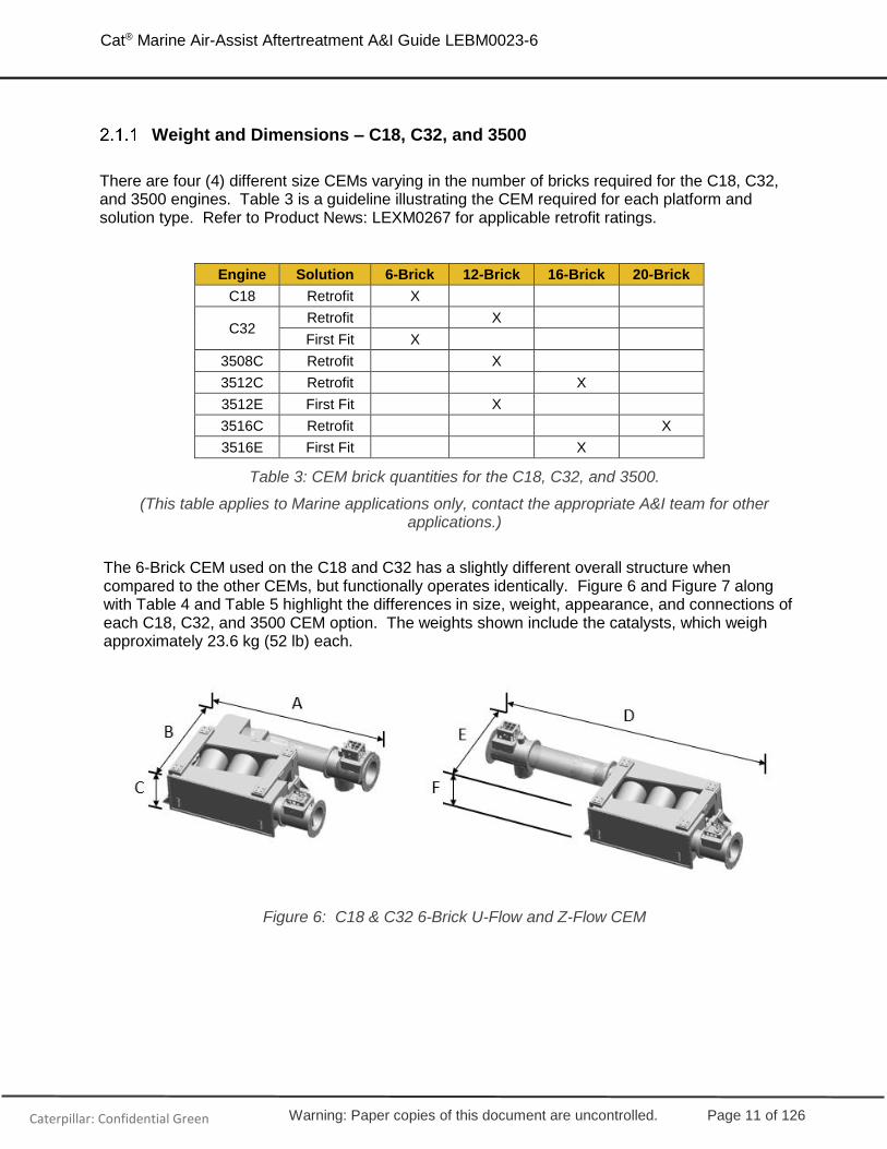
There are four (4) different size CEMs varying in the number of bricks required for the C18, C32, and 3500 engines. Table 3 is a guideline illustrating the CEM required for each platform and solution type. Refer to Product News: LEXM0267 for applicable retrofit ratings.
Engine Solution 6-Brick 12-Brick 16-Brick 20-Brick
C18 Retrofit X
C32 Retrofit X
First Fit X
3508C Retrofit X
3512C Retrofit X
3512E First Fit X
3516C Retrofit X
3516E First Fit X
Table 3: CEM brick quantities for the C18, C32, and 3500.
(This table applies to Marine applications only, contact the appropriate A&I team for other applications.)
The 6-Brick CEM used on the C18 and C32 has a slightly different overall structure when compared to the other CEMs, but functionally operates identically. Figure 6 and Figure 7 along with Table 4 and Table 5 highlight the differences in size, weight, appearance, and connections of each C18, C32, and 3500 CEM option. The weights shown include the catalysts, which weigh approximately 23.6 kg (52 lb) each.
Figure 6: C18 & C32 6-Brick U-Flow and Z-Flow CEM

Warning: Paper copies of this document are uncontrolled. Page 12 of 126
Cat® Marine Air-Assist Aftertreatment A&I Guide LEBM0023-6
Caterpillar: Confidential Green
Figure 7: C32 & 3500 12-Brick, 16-Brick, & 20-Brick U-Flow and Z-Flow CEM
U-Flow Z-Flow
CEM Size A
mm (in) B
mm (in) C
mm (in) Weight kg (lb)
D mm (in)
E mm (in)
F mm (in)
Weight kg (lb)
6-Brick 2,098 (83)
1,516 (60)
688 (28)
560 (1,235)
3,752 (148)
1,171 (47)
688 (28)
565 (1,246)
12-Brick 2,712 (107)
1,629 (65)
1,013 (40)
1,262 (2,782)
3,454 (136)
1,628 (65)
1,013 (40)
1,254 (2,765)
16-Brick 2,946 (116)
1,770 (70)
1,004 (40)
1,390 (3,064)
3,679 (145)
1,770 (70)
1,004 (40)
1,399 (3,084)
20-Brick 3,386 (134)
1,926 (76)
1,013 (40)
1,720 (3,792)
4,116 (163)
1,918 (76)
1,013 (40)
1,740 (3,836)
Table 4: CEM dry weights & dimensions for C18 - 3500 U-Flow and Z-Flow with catalysts installed
CEM Size Flange Size
6-Brick 12” ANSI Class 150 Modified – ½” thickness
12-Brick 14” ANSI Class 150 Modified – ½” thickness
16-Brick 18” ANSI Class 150 Modified – ½” thickness
20-Brick 20” ANSI Class 150 Modified – ½” thickness
Table 5: CEM Flange Sizes for the U-Flow & Z-Flow
NOTE: Always refer to the installation drawings available in EDDC and TMI for the most up -to-date and accurate information.

Warning: Paper copies of this document are uncontrolled. Page 13 of 126
Cat® Marine Air-Assist Aftertreatment A&I Guide LEBM0023-6
Caterpillar: Confidential Green
Weight and Dimensions – C280 / MaK
There is only one (1) style of CEM for the C280 / MaK, again it varies in bricks required based primarily on the number of cylinders of the engine. Table 6 illustrates the structure of the bricks inside the CEM. For example, 4x4x4 implies a cube of 4 bricks by 4 bricks by 4 bricks, totaling 64 bricks.
Engine Solution 4x4x2 4x4x3 4x4x4 5x5x4 6x6x3
C280-8 First Fit X
C280-12 First Fit X
C280-16 First Fit X
M20C First Fit X
6M25E First Fit X
8M25E / 9M25E First Fit X
M32E First Fit X
Table 6: CEM brick configurations for C280 / MaK engines.
Figure 8 along with Table 7, Table 8, Table 9, and Table 10 highlight the differences in size and weight of each C280 / MaK CEMs. The weights shown include the catalysts, which weigh approximately 20.9 kg (46 lb) each.
Note: Contact the Dealer Sales Support Team for additional MaK information.
Figure 8: C280 / MaK CEM & Mixing Tube

Warning: Paper copies of this document are uncontrolled. Page 14 of 126
Cat® Marine Air-Assist Aftertreatment A&I Guide LEBM0023-6
Caterpillar: Confidential Green
C280 CEM Mixing Tube
CEM Size #
Catalysts A
mm (in) B
mm (in) Weight kg (lb)
C mm (in)
D mm (in)
Weight kg (lb)
4x4x4 64 1,751
(69) 3,930 (155)
3,138 (6,918)
3,074 (122)
868 (35)
146 (322)
5x5x4 100 2,073 (82)
4,035 (159)
4,414 (9,731)
3,074 (121)
973 (39)
162 (357)
6x6x3 108 2,285 (90)
5,080 (200)
5,470 (12,059)
2,464 (97)
973 (39)
148 (326)
Table 7: C280 CEM & Mixing Tube dry weights & dimensions with catalysts installed. Dimensions are taken at the longest and widest section.
MaK CEM Mixing Tube
CEM Size Max #
Catalysts A
mm (in) B
mm (in) Weight kg (lb)
C mm (in)
D mm (in)
Weight kg (lb)
4x4x2 32 1,752 (69)
3,010 (119)
* 2,464 (97)
973 (39)
122 (269)
4x4x3 48 1,752 (69)
3,470 (137)
* 2,464 (97)
973 (39)
122 (269)
6x6x3 108 1,752 (69)
3,010 (119)
* 3,657 (144)
1192 (47)
264 (583)
Table 8: MaK CEM & Mixing Tube Dimensions. Dimensions are taken at the longest and widest section.
*Contact the Dealer Sales Support team for additional MaK information.

Warning: Paper copies of this document are uncontrolled. Page 15 of 126
Cat® Marine Air-Assist Aftertreatment A&I Guide LEBM0023-6
Caterpillar: Confidential Green
C280 CEM Mixing Tube
CEM Size # Catalysts Flange Size Flange Size
4x4x4 64 24” ANSI Class 150
Modified – ½” thickness 18” ANSI Class 150
Modified – ½” thickness
5x5x4 100 24” ANSI Class 150
Modified – ½” thickness 20” ANSI Class 150
Modified – ½” thickness
6x6x3 108 24” ANSI Class 150
Modified – ½” thickness 20” ANSI Class 150
Modified – ½” thickness
Table 9: C280 CEM & Mixing Tube Flange Sizes
MaK CEM Mixing Tube
CEM Size Max #
Catalysts Flange Size Flange Size
4x4x2 32 DN 500 DN 500
4x4x3 48 DN 600 DN 500
6x6x3 108 DN 900 DN 700
Table 10: MaK CEM & Mixing Tube Flange Sizes
NOTE: Always refer to the installation drawings available in EDDC and TMI for the most up -to-date and accurate information.

Warning: Paper copies of this document are uncontrolled. Page 16 of 126
Cat® Marine Air-Assist Aftertreatment A&I Guide LEBM0023-6
Caterpillar: Confidential Green
Mounting – C18, C32, and 3500
Mounting Orientation – U-Flow & Z-Flow
The C18, C32, and 3500 CEMs can be mounted in any orientation except with the service door down. Due to the weight of the catalysts, downward servicing is strongly discouraged. The service door is always located on the outlet side of the CEM, which can also aid in ensuring proper orientation. See Figure 9, Figure 10, and Figure 11 for examples. (Sensor box orientation will be covered later in this section.)
Figure 9: CORRECT Z-Flow orientation: Service Door & Sensor Box orientations are acceptable (covered later in this section)
Figure 10: INCORRECT Z-Flow orientation: Service Door Down (potential safety issue) & Sensor Box orientations are unacceptable (covered later in this section)

Warning: Paper copies of this document are uncontrolled. Page 17 of 126
Cat® Marine Air-Assist Aftertreatment A&I Guide LEBM0023-6
Caterpillar: Confidential Green
Figure 11: CORRECT Z-Flow orientation: Service Door & Sensor Box orientations are acceptable (covered later in this section)
Mounting Locations – U-Flow & Z-Flow
The U-Flow and Z-Flow CEMs provide several 4-bolt mounting pads (shown in orange in Figure 12). Although there are multiple pads, a proper mounting only requires using at least four (4) of them.
Four (4) sets of mounting brackets (shown in yellow in Figure 12) and 16 bolts (M20 x 2.5) are also provided. Each mounting bracket has an M28 hole for mounting the CEM. The shipyard can use their own mounting brackets as desired however, all brackets must be bolted to the mounting pads, welding is not permitted.

Warning: Paper copies of this document are uncontrolled. Page 18 of 126
Cat® Marine Air-Assist Aftertreatment A&I Guide LEBM0023-6
Caterpillar: Confidential Green
Figure 12: C18, C32, & 3500 (shown) Mounting Pads and Brackets
The provided brackets are not intended to be used in tension. If the CEM is mounted from above, a separate structure or vessel provided brackets must be used to support the weight of the CEM.
Figure 13: INCORRECT C18, C32, & 3500 Provided Mounting Bracket cannot be used in Tension
Mounting Orientation & Location – “Simplified” U-Flow & Z-Flow
The 3512E and 3516E also offer a simplified CEM. The simplified CEM only provides a bottom mounting support structure and therefore only four (4) mounting pad locations. The simplified CEM is offered in both a port and starboard orientation. (Refer to Figure 14).
Warning: Paper copies of this document are uncontrolled. Page 19 of 126
Cat® Marine Air-Assist Aftertreatment A&I Guide LEBM0023-6
Caterpillar: Confidential Green
Figure 14: Single Mounting Orientation for the Simplified 3500E U-Flow (shown) & Z-Flow
Mounting Method – U-Flow & Z-Flow
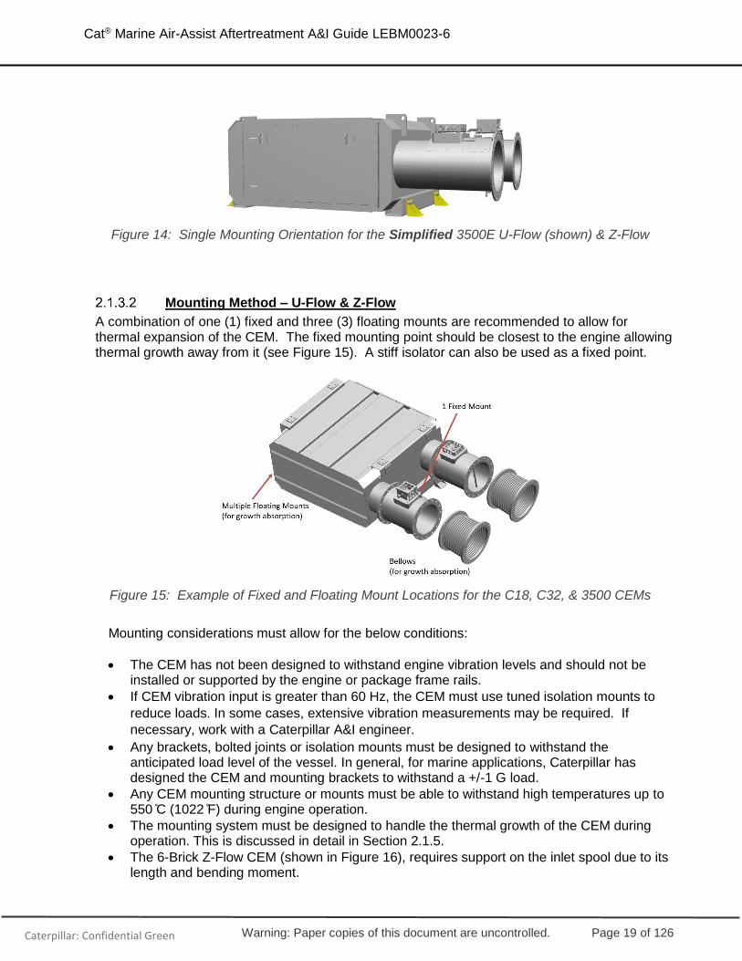
A combination of one (1) fixed and three (3) floating mounts are recommended to allow for thermal expansion of the CEM. The fixed mounting point should be closest to the engine allowing thermal growth away from it (see Figure 15). A stiff isolator can also be used as a fixed point.
Figure 15: Example of Fixed and Floating Mount Locations for the C18, C32, & 3500 CEMs
Mounting considerations must allow for the below conditions:
• The CEM has not been designed to withstand engine vibration levels and should not be installed or supported by the engine or package frame rails.
• If CEM vibration input is greater than 60 Hz, the CEM must use tuned isolation mounts to
reduce loads. In some cases, extensive vibration measurements may be required. If
necessary, work with a Caterpillar A&I engineer.
• Any brackets, bolted joints or isolation mounts must be designed to withstand the anticipated load level of the vessel. In general, for marine applications, Caterpillar has designed the CEM and mounting brackets to withstand a +/-1 G load.
• Any CEM mounting structure or mounts must be able to withstand high temperatures up to 550 C̊ (1022 F̊) during engine operation.
• The mounting system must be designed to handle the thermal growth of the CEM during operation. This is discussed in detail in Section 2.1.5.
• The 6-Brick Z-Flow CEM (shown in Figure 16), requires support on the inlet spool due to its length and bending moment.

Warning: Paper copies of this document are uncontrolled. Page 20 of 126
Cat® Marine Air-Assist Aftertreatment A&I Guide LEBM0023-6
Caterpillar: Confidential Green
Figure 16: C18 & C32 6-Brick Z-Flow CEM
Inlet and Outlet Spool Orientation – U-Flow & Z-Flow
The U-Flow and Z-Flow CEMS have inlet and outlet spools which are attached with a bolted flange connection. Both spools have a sensor box installed. The inlet spool also has a DEF injection lance installed opposite of the sensor box. This feature can be used to identify the inlet versus outlet spool.
The spools are installed via a bolted flange connection so that they can be easily removed and re-oriented during the installation. There are several requirements which must be considered when orienting the inlet and outlet spools.
• In a horizontal CEM installation as shown in Figure 17, the sensor boxes must be installed so the sensor box is oriented vertically in the upward direction (12 o’clock position). The spool can be rotated up to one (1) bolt hole in either direction (roughly the 11 o’clock to 1 o’clock position) but not further. This orientation prevents the pooling of moisture on the sensors.
Figure 17: Proper sensor box orientation on horizonal CEM orientations (inlet spool shown).
• In a vertical CEM installation, the inlet and outlet spools can be rotated freely without regard to the vertical sensor box orientation requirements, as shown previously in Figure 11.

Warning: Paper copies of this document are uncontrolled. Page 21 of 126
Cat® Marine Air-Assist Aftertreatment A&I Guide LEBM0023-6
Caterpillar: Confidential Green
• Clearance must be provided to remove and service the DEF injector lance, which is approximately 570 mm (22.4 in) for the C18, C32, and 3500.
• Clearance must be provided to service the electronics and sensors in the sensor boxes, which is approximately 150 mm (5.90 in)
Mounting – C280 / MaK
CEM Mounting Orientation
The C280 / MaK CEM must be installed in a vertical orientation; there is no option to install it in any other orientation.
The horizontally installed mixing tube will require additional piping to attach it to the CEM, see Figure 18. This piping must be stainless, preferably 316 or 409. Contact the proper Caterpillar A&I resource to discuss other mixing tube orientations.
Figure 18: C280 / MaK CEM & Mixing Tube Orientation

Warning: Paper copies of this document are uncontrolled. Page 22 of 126
Cat® Marine Air-Assist Aftertreatment A&I Guide LEBM0023-6
Caterpillar: Confidential Green
Mounting Locations – C280 / MaK
The C280 CEM must be secured on both the top and bottom.
1. Bottom Mounting
On the C280 / MaK vertical CEM modules, a total of eight (8) slotted 22 x 44 mm (0.87 x 1.73 in) mounts are provided on the bottom of the structure. All eight (8) of these mounting locations should be used for a proper installation.
The slots are located on two (2) sides of the CEM, four (4) on each side. The angular orientation of these slots, in conjunction with the Caterpillar provided spacer and mounting plate allow for thermal expansion of the CEM during operation. See Figure 19 highlighting one side of the CEM, showing four (4) slots and their orientation.
Figure 19: C280 / MaK CEM Bottom Mounting Slots
Each slot will utilize a Caterpillar provided spacer and mounting plate (Figure 20). These pieces will be used together as both a mounting an allowance for thermal expansion of the CEM.
Figure 20: Caterpillar provided Spacer and Mounting Plate

Warning: Paper copies of this document are uncontrolled. Page 23 of 126
Cat® Marine Air-Assist Aftertreatment A&I Guide LEBM0023-6
Caterpillar: Confidential Green
The spacer should be oriented in the slot such that it touches the outer most edge (Figure 21). As the CEM grows due to thermal expansion, it will expand outward along the spacer. (The spacers are intentionally taller than the foot of the CEM.) The mounting plate should be placed on top of the spacer and will aid in the ease of growth.
Figure 21: Correct placement of the Spacer (Left) and Mounting Plate (Right) to allow for Thermal Growth
Once all spacers and mounting plates are installed, both mounting sides of the CEM should look like Figure 22 and are now ready to be bolted into place.
Figure 22: C280 / MaK CEM Bottom Mount with Spacers and Mounting Plates installed

Warning: Paper copies of this document are uncontrolled. Page 24 of 126
Cat® Marine Air-Assist Aftertreatment A&I Guide LEBM0023-6
Caterpillar: Confidential Green
It is recommended to use eight (8) M20 (3/4”) SAE grade 8 bolts torqued to 250 +/- 40 Nm along with 2 washers (one on top of the mounting plate and one beneath the spacer) to mount the bottom of the CEM. Figure 23 shows the thickness of the bottom mounting structure. Note: It is mandatory that all mounting feet are contacting the mounting surface to distribute the load over the entire surface.
Figure 23: Thickness of the C280 / MaK CEM Bottom Mounting Prior to Torque being applied
2. Top Mounting On the top of the CEM, the four (4) lifting eye locations are used for securing it, preventing side motion. A 20-100 kN/mm (114,203 - 571,015 lbf/in) compressive spring load is required when the CEM is mounted in a cold resting state. This load should be oriented at 135 degrees to each side and align with the center of the CEM.
Figure 24: C280 / MaK CEM Top Mounting

Warning: Paper copies of this document are uncontrolled. Page 25 of 126
Cat® Marine Air-Assist Aftertreatment A&I Guide LEBM0023-6
Caterpillar: Confidential Green
Mixing Tube Orientation – C280 / MaK
With the C280 / MaK, the mixing tube is a separate piece from the CEM module and is installed horizontally. There are several requirements which must be considered when orienting this mixing tube:
• The sensor boxes on the mixing tube must be installed so that the sensor box is oriented vertically in the upward direction (12 o’clock position). This can be rotated up to one (1) bolt hole in either direction (roughly the 11 o’clock to 1 o’clock position), but not further. This requirement is the same as on the C32 and 3500 with the inlet and outlet spools and can be seen in Figure 17.
• Clearance must be provided to remove and service the DEF injector lance, which is approximately 723 mm (28.5 in) for the C280 and 938 mm (37 in) for the largest MaK CEM.
• Clearance must be provided to service the electronics and sensors in the sensor boxes, which is approximately 150 mm (5.90 in).
Mounting Method – C280 / MaK
Mounting considerations must allow for the below conditions:
• The CEM has not been designed to withstand engine vibration levels and should not be installed or supported by the engine or package frame rails.
• If CEM vibration input is greater than 60 Hz, the CEM must use tuned isolation mounts to
reduce loads. In some cases, extensive vibration measurements may be required. If
necessary, work with a Caterpillar A&I engineer.
• Any brackets, bolted joints or isolation mounts must be designed to withstand the anticipated load level of the vessel. In general, for marine applications, Caterpillar has designed the CEM and mounting brackets to withstand a +/-1 G load.
• Any CEM mounting structure or mounts must be able to withstand high temperatures up to 550 C̊ (1022 F̊) during engine operation.
The mounting system must be designed to handle the thermal growth of the CEM during operation. This is discussed previously in section 2.1.4.2 as well as the following section.

Warning: Paper copies of this document are uncontrolled. Page 26 of 126
Cat® Marine Air-Assist Aftertreatment A&I Guide LEBM0023-6
Caterpillar: Confidential Green
Thermal Growth
Due to the temperature in the exhaust system, the CEM will experience significant thermal growth, just like other exhaust components. The thermal growth rate for the stainless steel CEM is 0.0000124 m/m/ C̊ (0.00000689 in/in/ ̊F). This means that for every 100 deg C, the CEM will thermally expand 1.24mm per meter (for every 100 deg F, the CEM will expand 0.008 in/ft). Refer to Table 11 for a reference which can be used to estimate thermal growth of the CEM.
Temperature Rise (deg C)
Expansion Rate
(mm/m)
Net Expansion Per Total Original Length (mm)
1 meter 2 meters 3 meters 4 meters
100 1.2 1.2 2.4 3.6 /\4.8
200 2.4 2.4 4.8 7.2 9.6
300 3.7 3.7 7.4 11.1 14.8
400 5.0 5.0 10.0 15.0 20.0
500 6.2 6.2 12.4 19.5 24.8
600 7.4 7.4 14.8 22.2 29.6
Table 11: CEM estimated thermal expansion (Metric)
Figure 25: Example of the estimated thermal growth of the 12-brick U-Flow CEM due to a 500 deg C (932 deg F) temperature increase.
Compensation for thermal growth must be accounted for when mounting and installing exhaust piping, the CEM, and the mixing tube (for the C280). Recommendations include:
• Flexible exhaust bellows should be installed in the exhaust piping at the inlet and outlet of the CEM, or as close as possible. This will aid in minimizing additional stresses on the system due to thermal growth. Bellows are also recommended on the inlet of the mixing

Warning: Paper copies of this document are uncontrolled. Page 27 of 126
Cat® Marine Air-Assist Aftertreatment A&I Guide LEBM0023-6
Caterpillar: Confidential Green
tube for the C280 / MaK. Remember that all piping on the outlet side of the mixing tube to the inlet of the CEM, must be stainless steel.
• The C18, C32, and 3500 CEM mounting should use a combination of “fixed” and “floating” or “flexible” mounting locations. A floating or flexible mount refers to one which allows thermal growth in at least one direction. One (1) fixed or stiff isolator mounting should be used and positioned such that thermal growth is outward – away from the engine side. An example of this was shown in Figure 15.
• Additional details for the C280 / MaK CEM mounting information can be found in section 2.1.4.
Lifting – U-Flow & Z-Flow
The CEM is provided with four (4) M20x2.5 lifting eyes, all four (4) must be used during lifting. These can be removed and installed in any orientation required depending on the method of lift. Several examples are shown in Figure 26. These lifting eyes are rated to support the weight of the CEM only and should not be used to lift the CEM with any additional attachments. The lifting eyes have an acceptable lift angle of up to 90 degrees as shown in Figure 27. Due to the high temperatures seen by the CEM, all lifting eyes must be removed once the CEM is installed.
Figure 26: Example lifting methods for the CEM utilizing four (4) provided lifting eyes
Figure 27: Allowable lifting angle for provided lifting eyes
A spreader bar is not required provided the lifting straps do not contact the sensor boxes or DEF injection lance installed on the inlet and outlet spools.
Warning: Paper copies of this document are uncontrolled. Page 28 of 126
Cat® Marine Air-Assist Aftertreatment A&I Guide LEBM0023-6
Caterpillar: Confidential Green
When lifting or placing the CEM, it should not be allowed to rest on the inlet or outlet spools. If necessary, these spools can be removed during the lift. A fork truck should not be used to lift the CEM unless the CEM in placed on a suitable pallet. This is to prevent the forks from contacting and potentially damaging the CEM.
Lifting – C280 / MaK
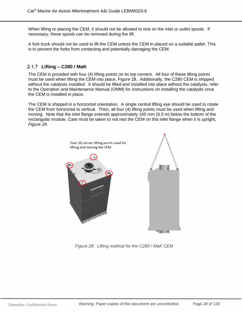
The CEM is provided with four (4) lifting points on its top corners. All four of these lifting points must be used when lifting the CEM into place, Figure 28. Additionally, the C280 CEM is shipped without the catalysts installed. It should be lifted and installed into place without the catalysts, refer to the Operation and Maintenance Manual (OMM) for instructions on installing the catalysts once the CEM is installed in place. The CEM is shipped in a horizontal orientation. A single central lifting eye should be used to rotate the CEM from horizontal to vertical. Then, all four (4) lifting points must be used when lifting and moving. Note that the inlet flange extends approximately 165 mm (6.5 in) below the bottom of the rectangular module. Care must be taken to not rest the CEM on this inlet flange when it is upright, Figure 29.
Figure 28: Lifting method for the C280 / MaK CEM

Warning: Paper copies of this document are uncontrolled. Page 29 of 126
Cat® Marine Air-Assist Aftertreatment A&I Guide LEBM0023-6
Caterpillar: Confidential Green
Figure 29: Lifting method to rotate the C280 / Mak CEM from horizontal to vertical
Service Access and Clearance – U-Flow & Z-Flow
DEF Injection Lance
To remove the DEF injection lance on the C18, C32, and 3500 CEMs, a minimum distance of 570 mm (22.4 in) is required as shown in Figure 30. If this clearance cannot be met due to equipment or structure interference, the inlet spool can be rotated, refer to section 2.1.3.3 for more details.
Figure 30: Service clearance required for DEF injection lance on the C18 / C32 / 3500.

Warning: Paper copies of this document are uncontrolled. Page 30 of 126
Cat® Marine Air-Assist Aftertreatment A&I Guide LEBM0023-6
Caterpillar: Confidential Green
Sensor Boxes
The inlet and outlet sensor boxes must be free from obstruction to allow access to service and replace sensors, at least 150 mm (5.90 in) is recommended.
Catalyst Removal
To remove and replace the C18, C32, and 3500 CEM catalysts, a minimum service clearance of 400mm (15.75 in) is required. Where possible, a clearance of 1000mm (39.4 in) is recommended. This is shown in Figure 31. Details on the procedure for installation and removal of the catalysts is given in the Disassembly and Assembly Instructions, M0075247. The lifting tool 399-9725 aids in catalyst removal, shown in Figure 32.
Figure 31: Recommended service clearance to remove and replace catalysts.
Figure 32: 399-9725 Lifting Tool in a Catalyst

Warning: Paper copies of this document are uncontrolled. Page 31 of 126
Cat® Marine Air-Assist Aftertreatment A&I Guide LEBM0023-6
Caterpillar: Confidential Green
Service Access and Clearance – C280
DEF Injection Lance
To remove the DEF injection lance on the C280 CEMs, a minimum distance of 723 mm (28.5 in) is required. The largest MaK lance removal is 938 mm (37 in). These can be seen in Figure 33. To provide this clearance, the inlet spool can be rotated, refer to section 2.1.3.3 for more details.
Figure 33: Service clearance required for DEF injection lance on the C280 & Largest MaK CEM
NOTE: Always refer to the installation drawings available in EDDC and TMI for the most up -to-date and accurate information.
Sensor Boxes
The inlet and outlet sensor boxes must be free from obstruction to allow access to service and replace sensors, at least 150 mm (5.90 in) is recommended.
Catalyst Removal
To remove and replace the C280 / MaK catalysts, a service door is provided at the top of one side of the CEM. The recommended clearance for the catalysts and support grid removal is given in Figure 34 and Table 12. Details on the procedure for installation and removal of the catalysts is given in the Assembly & Disassembly Instructions, UENR0127.

Warning: Paper copies of this document are uncontrolled. Page 32 of 126
Cat® Marine Air-Assist Aftertreatment A&I Guide LEBM0023-6
Caterpillar: Confidential Green
Figure 34: Recommended Clearance for Catalyst & Support Grid Removal for the C280 CEM
C280 CEM
CEM Size A
mm (in) B
Radius mm (in)
4x4x4 2411 (95) R1560 (R62)
5x5x4 2572 (102) R1560 (R62)
6x6x3 2737 (108) R1560 (R62)
Table 12: Recommended Clearance for Catalyst & Support Grid Removal for the C280 CEM
NOTE: Always refer to the installation drawings available in EDDC and TMI for the most up -to-date and accurate information.
Connections
Air and DEF are connected to the injection lance, located on the inlet spool (C18, C32, and 3500) or the mixing tube (C280 / MaK). Refer to Figure 35 as well as Table 13 for more information about these connection points.

Warning: Paper copies of this document are uncontrolled. Page 33 of 126
Cat® Marine Air-Assist Aftertreatment A&I Guide LEBM0023-6
Caterpillar: Confidential Green
Figure 35: CEM connections on injection lance.
Connection
Point Description Fitting Type
1 DEF inlet line to CEM 3/4"-16 STOR
2 Air inlet line to CEM 9/16”-18 JIC
Table 13: CEM connection details.
NOTE: Always refer to the installation drawings available in EDDC and TMI for the most up -to-date and accurate information.

Warning: Paper copies of this document are uncontrolled. Page 34 of 126
Cat® Marine Air-Assist Aftertreatment A&I Guide LEBM0023-6
Caterpillar: Confidential Green
2.2 PETU / Dosing Cabinet
The Dosing Cabinet or PETU has 3 primary functions / features that enable the system to maintain emissions compliance:
o Monitoring and dosing DEF o Monitoring and regulating compressed air o Housing an Aftertreatment Electronic Control Module (ECM)
A few key internal components are shown in Figure 36 below. Each dosing cabinet contains a DEF pump, which pulls DEF from the internal DEF Buffer tank to supply to the injector. The aftertreatment ECM will communicate with the engine over J1939 datalink via one of the front connection points (covered later in this section and shown in Table 15). Note: The Dosing Cabinet buffer tank only fills to 92% (this is discussed later in 2.2.8). Once the buffer tank level lowers to 62%, it will begin signaling for DEF from the Main Vessel DEF tank.
Figure 36: Internal view of the PETU / Dosing Cabinet

Warning: Paper copies of this document are uncontrolled. Page 35 of 126
Cat® Marine Air-Assist Aftertreatment A&I Guide LEBM0023-6
Caterpillar: Confidential Green
Weight and Dimensions
There are three variations of dosing cabinets available for the marine air-assist solution:
• 60 lph First Fit: Utilized on C32 and 3500 first fit solutions as well as MaK (6M20C, 8M20C, 9M20C, 6M25E, 8M25E, 9M25E, and 6M32E)
• 120 lph First Fit: Utilized on the C280 first fit solutions as well as MaK (8M32E & 9M32E)
• 60 lph Retrofit: Utilized on C18, C32, and 3500 retrofit IMO II/III switchable solutions The interface / connections are identical for the first fit Dosing Cabinets however, the space claim is different. The retro fit solution is similar but includes an additional top mounted display. A reference for overall dimensions and dry weight is given in Table 14. The two (2) variations (First fit & Retrofit) are also shown in Figure 37.
C32 / 3500 / MaK*
60 lph First Fit C280 / MaK*
120 lph First Fit C18 / C32 / 3500 60 lph Retro Fit
Length 940 mm (37.0 in)
1010 mm (39.8 in)
940 mm (37.0 in)
Width 500 mm (19.7 in)
553 mm (21.8 in)
500 mm (19.7 in)
Height 585 mm (23.0 in)
634 mm (25.0 in)
845 mm (33.3 in)
Dry Weight 100 kg (220 lb)
125 kg (276 lb)
123 kg (271 lb)
Table 14: Dosing cabinet reference dimensions and weight. *Note: MaK uses both First Fit cabinets, varying by product
Figure 37: Dosing cabinets; First Fit and Retro Fit NOTE: Always refer to the installation drawings available in EDDC and TMI for the most up-to-date and accurate information.

Warning: Paper copies of this document are uncontrolled. Page 36 of 126
Cat® Marine Air-Assist Aftertreatment A&I Guide LEBM0023-6
Caterpillar: Confidential Green
Mounting Orientation
The dosing cabinet must be installed in a level orientation with the mounting rails down as shown in Figure 37 (above). It is not acceptable to mount the dosing cabinet in any other orientation. Four (4) holes sized for an M10 bolt are provided in the bottom of the mounting rails and should be used for securing the dosing cabinet. The dosing cabinet is not designed to be subjected to engine vibration levels and should not be mounted to the engine or genset package frame. Multiple dosing cabinets can be mounted above one another if they are independently supported, ensuring the top cabinet is not resting directly on the cabinet beneath. If cabinets are mounted above each other, take special note of the control panel installed on the top of the retrofit cabinet, clearance must be provided for this unless it’s relocated to the side of the cabinet.
Lifting
To lift the dosing cabinet, insert two (2) straps through the slots of the mounting rails and lift from above. See Figure 38.
Figure 38: Dosing Cabinet Mounting Holes & Lifting Slots
Warning: Paper copies of this document are uncontrolled. Page 37 of 126
Cat® Marine Air-Assist Aftertreatment A&I Guide LEBM0023-6
Caterpillar: Confidential Green
Service Access and Clearance
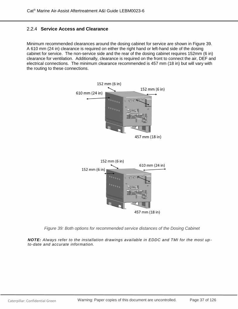
Minimum recommended clearances around the dosing cabinet for service are shown in Figure 39. A 610 mm (24 in) clearance is required on either the right hand or left-hand side of the dosing cabinet for service. The non-service side and the rear of the dosing cabinet requires 152mm (6 in) clearance for ventilation. Additionally, clearance is required on the front to connect the air, DEF and electrical connections. The minimum clearance recommended is 457 mm (18 in) but will vary with the routing to these connections.
Figure 39: Both options for recommended service distances of the Dosing Cabinet
NOTE: Always refer to the installation drawings available in EDDC and TMI for the most up -to-date and accurate information.

Warning: Paper copies of this document are uncontrolled. Page 38 of 126
Cat® Marine Air-Assist Aftertreatment A&I Guide LEBM0023-6
Caterpillar: Confidential Green
Installation and Venting
There are several requirements that must be considered when locating & venting the dosing cabinet in the vessel.
Figure 40: Example of a Dosing Cabinet Vent Line when the Vessel DEF Tank is below the Injector
(1) DEF line to Injector (2) Dosing Cabinet should be below the Injector (3) Dosing Cabinet Vent Line (4) Vessel DEF Tank Vent Line (5) OSHA DEF Overflow Container (shown in Figure 41)
Location (Refer to Figure 40)
• The top of the dosing cabinet must be installed below the level of the injector (2). The DEF line from the injector to the dosing cabinet must have a continuous downward slope of at least 10° above horizontal (if not vertical), with no loops or p-traps (1). This will allow DEF to easily return to the dosing cabinet and prevent potential plugging of the lines. Keep lines away from sharp edges and vibration.
• A maximum DEF pressure drop of 200 kPa (29 psi) from the dosing cabinet to the CEM cannot be exceeded (1).
• The dosing cabinet must be maintained at an ambient temperature between -11°C to 45°C (12°F to 113°F) when 32.5% DEF is used or 0°C to 45°C (32°F to 113°F) with 40% DEF usage. Installing the dosing cabinet in the stack or near exhaust components is not recommended. (Refer to Section 2.4 for information about the affects of temperature on DEF).

Warning: Paper copies of this document are uncontrolled. Page 39 of 126
Cat® Marine Air-Assist Aftertreatment A&I Guide LEBM0023-6
Caterpillar: Confidential Green
Venting (Refer to Figure 40 and Figure 41)
• The dosing cabinet DEF vent line must route continuously away from the vent port without any kinks or loops that would allow DEF pooling in the line (3).
• The vent line must be routed back to vessel DEF tank vent line or vented out of the vessel independently (3).
o Note: Routing back to the Vessel DEF tank itself creates the potential for DEF to flow into the dosing cabinet’s vent line, overfilling the buffer tank in the dosing cabinet.
• If the vessel DEF tank is located above the CEM injector, a local/OSHA approved container must be provided (compatible with DEF). This is required for the unlikely event of a dosing cabinet overfill. It is recommended to install a sensor in this overflow container to alert when liquid is present (5).
There is a Purge process enabling DEF in the line to the injector to be returned to the buffer tank in the dosing cabinet. Refer to section 2.2.8, for information about this Purge Process.
Figure 41: Example of a Dosing Cabinet Vent Line and Overflow Container when the Vessel DEF Tank is above the Injector
(Definitions are above the image)

Warning: Paper copies of this document are uncontrolled. Page 40 of 126
Cat® Marine Air-Assist Aftertreatment A&I Guide LEBM0023-6
Caterpillar: Confidential Green
Connections
The dosing cabinet controls external DEF, Air, and Electrical components via the connection points on the front face of the cabinet. Each connection is shown in Figure 42 and Table 15. Note: All lines carrying DEF must meet requirements stated in ISO 22241-1 (32.5%) and ISO 18611 (40%). Details of DEF, Air and Filter requirements into the dosing cabinet are found in sections 2.4 and 2.5.
Figure 42: Dosing Cabinet Connections
Connection Description Fitting Type
1 Service Tool Connector 9 Pin
2 Wiring harness connector to engine ECM 23 Pin Connector
3 Wiring harness connector to main DEF tank (level
sensor/transfer pump) 14 Pin Connector
4 Wiring harness connector to CEM 21 Pin Connector
5 DEF Vent Port ½” BARB
6 AC Power In Grommet for wiring & 3 terminal Blocks
7 DEF Outlet to CEM
3/8” Quick Connect SAE J2044
(No. 6 STOR (Straight Thread O-Ring) if Quick Connect Removed)
8 DEF Inlet 3/4-16” JIC
9 Air Outlet to CEM No. 6 STOR (Straight Thread O-Ring)
10 Air Inlet 9/16-18” JIC
11 DC Power for Display 3 pin Connector
Table 15: Dosing Cabinet Connections

Warning: Paper copies of this document are uncontrolled. Page 41 of 126
Cat® Marine Air-Assist Aftertreatment A&I Guide LEBM0023-6
Caterpillar: Confidential Green
Dosing Cabinet Operation & Schematic
The system goes through a start-up check, verifying air and DEF pressure sensor operation, and system readiness for dosing (Refer to Figure 43 and Figure 44). After all requirements are met, the Aftertreatment ECM will activate the dosing pump, moving DEF from the buffer tank to the injector. The Air Inlet Solenoid (S1) is energized (open) allowing air to the injector. The Aftertreatment ECM is constantly monitoring air and DEF pressure for system operational health.
The Aftertreatment ECM controls the DEF fill valve to the buffer tank. When the buffer tank’s level drops below 62%, the Aftertreatment ECM energizes the DEF Inlet Solenoid Valve (S3) to open and fill the buffer tank. The DEF pressure requirements to the tank are 34.5 - 69 kPa (5-10 psi) at a flow rate of 5.7 – 9.5 liters per minute (1.5 – 2.5 gpm).
Purging the system is accomplished by leaving the Air Inlet Solenoid (S1) energized (open), and de-energizing Purge Solenoid (S2) to open. This allows compressed air to assist DEF purge flow back to the buffer tank ensuring no DEF remains in the injection line (S3 is closed during the purge cycle). (Refer to the next section for more details.)
Figure 43: Schematic with Dosing Cabinet Details
The following components are REQUIRED unless noted:
(1) Customer Supplied: Air Pressure Regulator: 724-1068 kPa (105-155 psi) (2) Customer or Caterpillar Supplied: Filter/Oil Water Separator (Cat Option: 267-5286) (3) Cat Supplied: Dosing Cabinet Air Pressure Regulator: 442 +/- 27 kPa (64 +/- 4 psi) (4) Customer Supplied: DEF Filter: 100µm (recommended) (5) Customer Supplied: Pressure Regulator: 34.5-69 kPa (5-10 psi) (6) Customer Supplied: Pressure Relief Valve: 69 kPa (10 psi) (7) Customer or Caterpillar Supplied: DEF Filter: 40µm (Cat Option: 491-6779)
Dosing Cabinet Solenoid Valves
(S1) Air Inlet (S2) DEF Purge (S3) DEF Inlet

Warning: Paper copies of this document are uncontrolled. Page 42 of 126
Cat® Marine Air-Assist Aftertreatment A&I Guide LEBM0023-6
Caterpillar: Confidential Green
Dosing Cabinet Air / DEF Purge
When the engine shuts down, the system is designed to purge all DEF back to the buffer tank inside the dosing cabinet. This prevents a potential blockage that could occur due to DEF crystalizing in the lines or pump. DEF is also purged when a DEF related fault code is active. The purge cycle takes approximately 2 minutes to complete after the engine has been shut down. Do not remove the main power or keyswitch power from the aftertreatment system until the purge system has completed. If a purge process doesn’t complete, a diagnostic code is active upon the next start sequence. Once normal dosing operation is achieved, the code is cleared, but will show on logged ECM history. The buffer tank only fills to approximately 92% during normal operation. This allows ample space for DEF returning via the purge process.
Figure 44: Air / DEF flow through the Dosing Cabinet

Warning: Paper copies of this document are uncontrolled. Page 43 of 126
Cat® Marine Air-Assist Aftertreatment A&I Guide LEBM0023-6
Caterpillar: Confidential Green
Dosing Cabinet / PETU Symbols
Figure 45 below shows the symbols on the Dosing Cabinet / PETU
Figure 45: Dosing Cabinet / PETU Symbols

Warning: Paper copies of this document are uncontrolled. Page 44 of 126
Cat® Marine Air-Assist Aftertreatment A&I Guide LEBM0023-6
Caterpillar: Confidential Green
2.3 Optional Caterpillar Supplied Transfer Pump
In most vessels, a DEF Transfer Pump will be required to supply DEF at the required pressure 34.5-69 kPa (5-10 psi) during normal operation. A pressure regulator and relief valve are required prior to the dosing cabinet to ensure pressure does not exceed the 69kPa (10 psi) limit. It may be possible to obtain this pressure via a gravity feed from the vessel DEF tank (note that the Dosing Cabinet would have to be at least 3.66 m (12 feet) below the main tank to consider this option, assuming 9.81 kPa/m (0.433 psi/ft).
Caterpillar offers a DEF transfer pump capable of servicing several dosing cabinets and a combination of both of the Air Assisted and Airless DEF dosing systems (Refer to Figure 46). The Transfer Pump has two modes, manual and automatic. Manual mode is only used for testing and troubleshooting. When in automatic mode, the pump receives a fill command from the dosing cabinet control requesting DEF be supplied. When the DEF Transfer Pump receives a fill signal, it activates the pump to run until the fill signal terminates. The pump will then continue to run for a brief period (~30 minutes) before shutting off and waiting for the next fill signal. Also included with the DEF Transfer Pump is a primary DEF strainer and a secondary bypass screen. The secondary bypass may be used to continue operation while servicing the primary. Figure 47 shows the layout of the Cat Transfer Pump.
For more information about the DEF Transfer Pump and installation requirements, refer to:
• SISWeb for M0089817 (Transfer Pump Manual)
• SISWeb for UENR8335 (DEF Transfer Pump Electrical)
• TMI - physical data section
• TMI for a link to current EDDC drawings
Figure 46: Electrical Connections of one (1) Transfer Pump into Multiple Dosing Cabinets
The DEF transfer pump relay, shown in Figure 46, is part of the panel on the transfer pump skid. If the Cat transfer pump isn’t used, this relay will have to be provided by the customer/shipyard.

Warning: Paper copies of this document are uncontrolled. Page 45 of 126
Cat® Marine Air-Assist Aftertreatment A&I Guide LEBM0023-6
Caterpillar: Confidential Green
Figure 47: Layout of the Cat Transfer Pump
Cat Transfer Pump Dimensions
Figure 48: Cat DEF Transfer Pump Dimensions

Warning: Paper copies of this document are uncontrolled. Page 46 of 126
Cat® Marine Air-Assist Aftertreatment A&I Guide LEBM0023-6
Caterpillar: Confidential Green
Cat Transfer Pump Schematic
The below schematic highlights mechanical components of Cat Transfer Pump.
PI = Pressure Indicator, PS = Pressure Sensor, CV = Check Valve
Figure 49: Cat DEF Transfer Pump
The following components are REQUIRED unless noted: (1) Customer Supplied: DEF Filter: 100µm (recommended) (2) Caterpillar Supplied: Transfer Pump Pressure Relief Valve: 500 kPa (72.5 psi) (3) Customer Supplied: Pressure Regulator: 34.5-69 kPa (5-10 psi) (4) Customer Supplied: Pressure Relief Valve: 69 kPa (10 psi) (5) Caterpillar Supplied: Dosing Cabinet Vent (6) Customer or Caterpillar Supplied: DEF Filter: 40µm, (Cat Option: 491-6779) (7) Caterpillar Supplied: Dosing Cabinet Solenoid Refill Valve
• Pressure regulators must be installed before each Dosing Cabinet to ensure that the pressure at each Dosing Cabinet is between 34.5–69 kPa (5-10 psi).
• Pressure relief valve on the DEF Transfer Pump should be set at its maximum valve of 500 kPa (72.5 psi).
• Pressure relief valves should be placed between each pressure regulator and corresponding Dosing Cabinet. These pressure relief valves should be set to 69 kPa (10 psi). They will help purge any trapped pressure in the line between the pressure regulators and Dosing Cabinets back to the bulk tank.

Warning: Paper copies of this document are uncontrolled. Page 47 of 126
Cat® Marine Air-Assist Aftertreatment A&I Guide LEBM0023-6
Caterpillar: Confidential Green
2.4 Diesel Exhaust Fluid (DEF) System
Overview
Diesel Exhaust Fluid (DEF) is a relatively inexpensive urea solution that enables Cat engines equipped with Selective Catalytic Reduction (SCR) to reduce NOx emissions by up to 93%. DEF is a colorless liquid made up of high purity urea and deionized water.
DEF Selection
For Marine SCR applications, the required DEF solution must meet ISO 22241-1 (DEF 32.5%), ISO 18611 (DEF 40%), Caterpillar specifications SEBU6251, or DIN V70070 standards. These standards are designed around DEF solutions of approximately 32.5% and 40% concentrations. (Due to the high risk of contaminants that could potentially damage the SCR system, Caterpillar does not allow the use of agricultural grade urea in Cat SCR systems.)
The advantage of 32.5% concentration is that it provides the lowest possible freezing point, -11°C (12°F) while 40% concentration freezes is at 0°C (32°F). The 40% solution, having a higher concentration, has the advantage of using less DEF per the amount of fuel used and potentially a smaller main DEF tank design.
DEF 32.5% 40%
Freezing Point -11°C (12°F) 0°C (32°F)
Table 16: DEF Freezing Temperatures
The quality of DEF rapidly degrades when stored at high temperatures. The ideal storage temperature for DEF is shown in Table 17. DEF that is stored above 35°C (95°F) for longer than one month must be tested before use.
Refer to ISO 22241 & 18611 for the most updated information storage temperature information.
Expected DEF Life 32.5 % DEF Storage Temperature 40% DEF Storage Temperature
Ideal Storage Temperature -9°C to 25°C
(15°F to 77°F) 2°C to 25°C
(36°F to 77°F)
18 Months Below 25°C (77°F) Below 25°C (77°F)
12 Months 25°C to 30°C (77°F to 86°F)
25°C to 30°C (77°F to 86°F)
6 Months 30°C to 35°C (86°F to 95°F)
30°C to 35°C (86°F to 95°F)
1 Month – Test Before Use Above 35°C (95°F) Above 35°C (95°F)

Warning: Paper copies of this document are uncontrolled. Page 48 of 126
Cat® Marine Air-Assist Aftertreatment A&I Guide LEBM0023-6
Caterpillar: Confidential Green
Table 17: DEF Expected Life based on Storage Temperature
Changes in DEF concentration can occur for a variety of reasons, including evaporation of water, degradation of urea, or contamination. Caterpillar offers 2 Refractometers for concentration testing, a Brix Digital (360-0774), and an Analog Refractometer (431-7087).
DEF is typically colorless and clear. A visual inspection should also be performed as any changes in color and clarify indicate a quality issue.
Material Selection for DEF
Material compatibilities must be considered in the DEF storage and delivery system due to the caustic corrosive nature of the liquid. Refer to ISO 22241 and ISO 18611 prior to any material selection. RECOMMENDED Materials Include: ▪ Stainless Steel (304, 304L, 316, 316L, 409, 439)
▪ Highly alloyed austenitic Cr-Ni and Cr-Ni-Mo Steels
o Titanium
o Polyethylene
o Polypropylene
o Polyisobutylene
o Perfluoroalkoxyl alkane (PFA)
o Polyfluroethylene (PFE)
o Polyvinylidenefluoride (PVDF)
o Polytetrafluroethylene (PTFE)
o Teflon (PFA)
▪ Seal/Hose Materials – EPDM (1E0712B) and NBR (1E0741)
NON-RECOMMENDED Materials Include:
▪ Unalloyed Steel
▪ Galvanized Steel
▪ Aluminum / Aluminum Alloys
▪ Magnesium
▪ Copper
▪ Brass
▪ Metals and Plastics coated with Nickel
▪ Nonferrous Metals and Alloys (copper, copper alloys, zinc, and lead)
Figure 50: Cat® Brix & Analog Refractometer Offerings, 360-0774 and 431-7087

Warning: Paper copies of this document are uncontrolled. Page 49 of 126
Cat® Marine Air-Assist Aftertreatment A&I Guide LEBM0023-6
Caterpillar: Confidential Green
Refer to PELJ1160 for additional information on DEF fluids (available on catpublications.com).
DEF Handling Procedure, Transport & Cleanliness
Ensure that equipment used to transfer DEF is made from recommended materials. Any hoses or other non-metallic transfer equipment should be made from Nitrile Rubber (NBR), Fluoroelastomer (FKM), and/or Ethylene Propylene Diene Monomer (EPDM). (Refer to ISO 22241 and ISO 18611 prior to any material selection.) DEF should be transported between storage temperature recommendations shown in Table 17.
Contaminants can degrade the quality and life of DEF. Therefore, it is recommended to filter DEF as it’s dispensed using a DEF compatible filter, preferably a mesh-type of compatible metals, such as stainless steel. The filter should be used exclusively with DEF. (Refer to SEBU6251 - Contamination Control for detailed cleanliness recommendations)
When filling the dosing cabinet buffer tank manually, clean the filler cap and surrounding area prior to dispensing DEF.
Spills and leaks: Spills should be cleaned immediately, and surfaces wiped and rinsed with warm water. Use caution when dispensing DEF near an engine that has recently been running. Spilling DEF onto hot components will cause it to vaporize, which can be harmful.
Due to the corrosive nature of DEF, the condition of hoses and other non-metallic components should be monitored for signs of degradation. DEF leaks are easily recognizable by white urea crystals that accumulate at the site of the leak (
Figure 51). Solid DEF is very corrosive to galvanized or unalloyed steel, aluminum, copper, and brass, so leaks should be addressed immediately to ensure no damage to surrounding hardware.
.
Figure 51: DEF Crystallization

Warning: Paper copies of this document are uncontrolled. Page 50 of 126
Cat® Marine Air-Assist Aftertreatment A&I Guide LEBM0023-6
Caterpillar: Confidential Green
Vessel DEF Tank
Tank Shape, Temperature, and Connections
The shipyard or installer must provide a vessel DEF tank and delivery system. Consideration for both high and low temperatures must be considered with tank design. If the location of the tank within the vessel can’t meet temperature requirements, (see Table 17), then a way to cool or heat the fluid must be installed in the vessel DEF tanks.
If there is a possibility of DEF freezing, the tank would need a heater large enough to thaw it. The density of frozen DEF is lower than the liquid, so it would float. To ensure complete thawing, at least part of the heating source must be located at the bottom of the tank. As DEF is consumed, the level in the tank reduces and cold DEF approaches the heater. Adequate protection is recommended to keep frozen DEF, sludge and sediment from blocking the port.
Irregular tank shapes are acceptable if air pockets and/or frozen DEF inside the ridges or any contours of the tank can be avoided. To facilitate the thawing process, the tank should have a simple rectangular or trapezoidal shape so that the base of the tank is slightly larger than the top of the tank.
Tank Volume
DEF tanks must be sized such that sufficient DEF is always available to operate the SCR system. The amount of DEF consumed by the engine can be estimated as a fraction of the engine fuel burn. DEF consumption by the engine will be approximately 5-10% for C18, C32, 3500, and MaK engines and upwards of 15% for C280 engines. Consult TMI Performance Data or work with the Caterpillar A&I team for actual numbers for each engine rating.
Caterpillar recommends a capacity safety margin of 5% of the total tank volume to ensure adequate supply (2% of which is a margin for freeze protection). If a vessel operating in EPA areas runs out of DEF, the operator must report each instance to the EPA within 30 days. Each instance of insufficient amounts of DEF will be recorded in nonvolatile memory by the engine. Refer to the Operation & Maintenance Manual for recordable codes.
Guideline of DEF to Fuel Consumption
Engine Fuel DEF
C18/C32/3500 100% 5-10%
C280 100% 15%
MaK 100% 5-10%
Table 18: DEF to Fuel Consumption Guideline

Warning: Paper copies of this document are uncontrolled. Page 51 of 126
Cat® Marine Air-Assist Aftertreatment A&I Guide LEBM0023-6
Caterpillar: Confidential Green
Examples of DEF to Fuel Consumption
Engine Fuel 32.5% DEF 40% DEF
3516E 3386bhp / 2525bkW
EM1756 100% 6.0% 4.6%
3516E 2682bhp / 2000bkW
EM1766 100% 6.6% 5%
C280-12 4962bhp / 3700bkW
EM0850 100% 7.4% 5.7%
C32 Retro Fit 1600bhp / 1193bkW
EM2768 100% 3.2% 2.4%
Table 19: Example DEF to Fuel Ratio – Refer to TMI for the most up to date data
NOTE: Always refer to TMI or A&I personnel for the most up-to-date and accurate information.
Tank Materials
Non-crosslinked polyethylene (PE) is the material of choice for DEF tanks. It provides a wide temperature range of operation, has good strength properties, allows for flexibility in “shaping”, low weight, and has been used in other DEF applications. Stainless Steel tanks are also a viable option. If using a coating on a steel tank, make sure the coating is compatible with DEF and completely seals the tank to prevent contact with DEF. If DEF touches steel, it will dissolve the metal, plug valves, and other components of the aftertreatment system.
Tank Sensors
DEF Temperature Sensor
A vessel storage tank temperature sensor may be installed and connected to the Cat system.
Temperature sensor requirements include:
• Operating temperature range: –40°C and 150°C (probe end), –40°C and 120°C
(connector end)
• Vibration limits: 30Grms X 3 sigma for 0.03% of operational lifetime
• Painted using the Electrostatic painting process
• Salt and DEF corrosion-resistant.
DEF Level Sensor
A low level DEF tank sensor is required on the main DEF tank per EPA 1042 regulation
Warning: Paper copies of this document are uncontrolled. Page 52 of 126
Cat® Marine Air-Assist Aftertreatment A&I Guide LEBM0023-6
Caterpillar: Confidential Green
guidelines. Caterpillar provides a connection point on the dosing cabinet for a vessel DEF
tank sensor via the Dosing Cabinet Junction boxes, Terminals 19 & 20 on Circuits 410 &
A487 (shown in Figure 67, Figure 68, Figure 69, and Figure 70). The sensor needs to be salt
and DEF corrosion-resistant, with an operating temperature range of –40°C to 85°C.
If the main DEF tank low sensor is connected to the dosing cabinet junction box, the system
will warn the vessel operator that the DEF main tank is low. No reportable faults are
recorded for low main tank volume. A reportable fault is recorded if the buffer tank in the
dosing cabinet runs completely out of DEF. The low-level sensor input into the dosing
cabinet ECM is a switch input to GND.
DEF Level Warning Light
The installation of warning light indicating a low level of DEF in the main tank is
recommended. The warning light should be set at a level in the tank that would allow
adequate time to get quality DEF and refill the main tank.
DEF Flow
DEF into Vessel Tank
An inlet strainer is required to prevent large debris from entering the fill port of the Vessel DEF tank. The strainer should be made of stainless steel with 30-mesh / 500-micron filtration.
DEF into the Transfer Pump
A course 100-micron filter must be located at the end of the DEF pickup line in the tank to keep frozen chunks of DEF and debris out of the delivery system.
DEF into the Dosing Cabinet
A 40-micron with Beta > 1000 filter must be installed before the dosing cabinet. It must meet ISO 22241-1 (32.5%) or ISO 18611 (40%) quality requirements with a maximum particle size of 40 microns. The filter screen needs to be able to handle 5.67 liters/min within a pressure range of 34.5 to 69 kPa (5 to 10psi). The filter should be installed as close as possible to the inlet port of the dosing cabinet. An isolation valve may be considered for serviceability. Caterpillar has released a 491-6779 DEF filter which meets all requirements for DEF and flow into the dosing cabinet.
The dosing cabinet stainless-steel connection point for DEF, does include a screen, but this does not replace the need for the 40-micron filter.
If the system will be shutting down in freezing conditions or put into storage, the screen filter and supply line should be drained. The customer is responsible for protecting the DEF supply line from freezing and damage from foreign objects (a stainless-steel supply line is recommended).
Refer to Section 2.2 for Dosing Cabinet Mounting and Venting Information.

Warning: Paper copies of this document are uncontrolled. Page 53 of 126
Cat® Marine Air-Assist Aftertreatment A&I Guide LEBM0023-6
Caterpillar: Confidential Green
DEF into the CEM
DEF lines are to be installed following instructions based on DIN 20066 part 4. The line from the dosing cabinet to the injector must have a constant downward slope back to the dosing cabinet (if not vertical). DEF must be able to easily flow back to the dosing cabinet without any residual being left in the line. The maximum pressure drop from the cabinet to the injector is 200 kPa (29 psi) therefore, it is recommended that the inside diameter of the line be greater than 5.5 mm.
DEF Flow Schematic
The below schematic highlights Caterpillar vs customer supplied mechanical elements of the DEF system.
Figure 52: DEF Flow Schematic (assuming 3 engines)
The following components are REQUIRED unless noted:
(1) Customer Supplied: DEF Filter: 100µm (recommended) (2) Customer Supplied: Pressure Regulator: 34.5-69 kPa (5-10 psi) (3) Customer Supplied: Pressure Relief Valve: 69 kPa (10 psi) (4) Cat Supplied: Dosing Cabinet Vent (5) Customer or Caterpillar Supplied: DEF Filter: 40µm, (Cat Option: 491-6779) (L1) Low Level Sensor: Required on the vessel DEF tank per EPA regulations. (L2) High Level Sensor

Warning: Paper copies of this document are uncontrolled. Page 54 of 126
Cat® Marine Air-Assist Aftertreatment A&I Guide LEBM0023-6
Caterpillar: Confidential Green
2.5 Air System
Overview
This air-assisted aftertreatment system utilizes compressed air along with DEF for three main reasons:
• To assist in the atomizing of DEF as it is injected into the exhaust stream to improve NOx conversion and reduce DEF usage
• To keep the nozzle clean and cool, thus preventing any plugging.
• To purge the DEF line during shutdown to prevent DEF crystallization in the nozzle
Air Supply Requirements
The air supply to each dosing cabinet must meet the specifications in Table 20.
Air Supply Requirements
Air Quality (-40°C minimum air Temp)
Air Quality (3°C minimum air Temp)
ISO 8573.1:2010 [5:2:4]*
ISO 8573.1:2010 [5:4:4]*
Air Temperature -40C to 50C (-40F to 122F)
Air Flow for 3500/C280
Air Flow for C18/C32
Air Flow for C32 Retrofit
0.28 m3/min (10 SCFM)
0.113 m3/min (4 SCFM)
0.28 m3/min (10 SCFM)
Air Consumption Continuous during engine operation, purge, and after
shutdown
OEM Supply Operational Air Pressure
(Measured at Dosing Cabinet Air Strainer Inlet)
Minimum: 482 kPa (70 psi)
Recommended: 724 – 1068 kPa (105-155 psi)
Internally Regulated System Air Pressure Target
(Pressure used for System Diagnostics) 441 +/- 27 kPa (64 +/- 4 psi)
Air Pressure at Startup
Aftertreatment ECM will activate low air pressure alarm ONLY after CEM inlet temperature reaches a
temperature threshold – AND – system internally regulated pressure is <375 kPa. Alarm will de-activate
once pressure is >375 kPa.
Purge Air Pressure at Shutdown
(Purges back to buffer tank) >482 kPa (70 psi) for 180 sec
Maximum Airline Pressure Drop from Dosing Cabinet to Lance
6.89 kPa (1 psi)

Warning: Paper copies of this document are uncontrolled. Page 55 of 126
Cat® Marine Air-Assist Aftertreatment A&I Guide LEBM0023-6
Caterpillar: Confidential Green
Coalescing Filter / Separator – Min Rating
(OEM supplied or Cat 267-5286
90% Efficient
Pressure: 1069 kPag (155 psig)
Flow: 0.85 m3/min (30 SCFM)
Table 20: Air Supply Requirements
*ISO 8573.1:2010 [A:B:C] where:
A is the purity class for particles
B is the purity class for humidity and liquid water
C is the purity class for oil
Air Line Requirements (Dosing Cabinet to Injector)
The air supply line used to deliver air from the dosing cabinet to the injector must be able to provide 442 +/- 27 kPa (64 +/- 4 psi) at maximum flow capacity. All air lines must progress continuously without air locks or line bends that would allow condensation to form or prevent proper air flow through the system.
Water / Oil Separator
The dosing cabinet requires customer supplied air which meets the ISO 8573.1 requirements, specified in Table 20. The dosing cabinet does contain a secondary air screen filter at the dosing cabinet air inlet port (Male 3/8” JIC). It is required that an oil / water separator be installed prior to this connection to catch any water in the lines prior to the cabinet; the 267-5286 filter is available from Cat.
Air System Mechanical Schematic
The below schematic highlights Caterpillar vs customer supplied mechanical elements of the air system.

Warning: Paper copies of this document are uncontrolled. Page 56 of 126
Cat® Marine Air-Assist Aftertreatment A&I Guide LEBM0023-6
Caterpillar: Confidential Green
Figure 53: Air System Schematic
The following components are REQUIRED:
(1) Customer Supplied: Air Pressure Regulator: 724-1068 kPa (105-155 psi) (2) Customer or Caterpillar Supplied: Oil/Water Separator, (Cat Option: 267-5286) (3) Cat Supplied: Dosing Cabinet Air Pressure Regulator: 442 +/- 27 kPa (64 +/- 4 psi) (4) Cat Supplied: Dosing Cabinet Solenoid Valve
2.6 Exhaust System
Overview
Examples of the engine exhaust system with aftertreatment are shown in Figure 54, Figure 55, and Figure 56 below. The engine, CEM, and mixing tube (for the C280 / MaK) are supplied by Cat. The exhaust piping and muffler are supplied by the shipyard. The C280 / MaK does require OEM/Shipyard supplied stainless steel piping between the mixing tube and CEM. Caterpillar recommends 409 or 316 Stainless Steel for all piping between the DEF injector and CEM. The exhaust system must be insulated, except for the sensor boxes, which must not be covered. The spools and sensor boxes must be oriented such that there isn’t the potential for any pooling liquid, which could damage the sensors (refer to 2.1.3.3 for more information). On overview of the engine exhaust system with installed aftertreatment is shown in Figure 54, Figure 55, and Figure 56. (The engine and CEM module are Caterpillar supplied while the exhaust piping, muffler, bellows, insulation, and other exhaust components, are shipyard supplied.) Refer to the Exhaust Systems A&I guide LEBW4970 for additional details on best practices including exhaust support thermal expansion and backpressure.
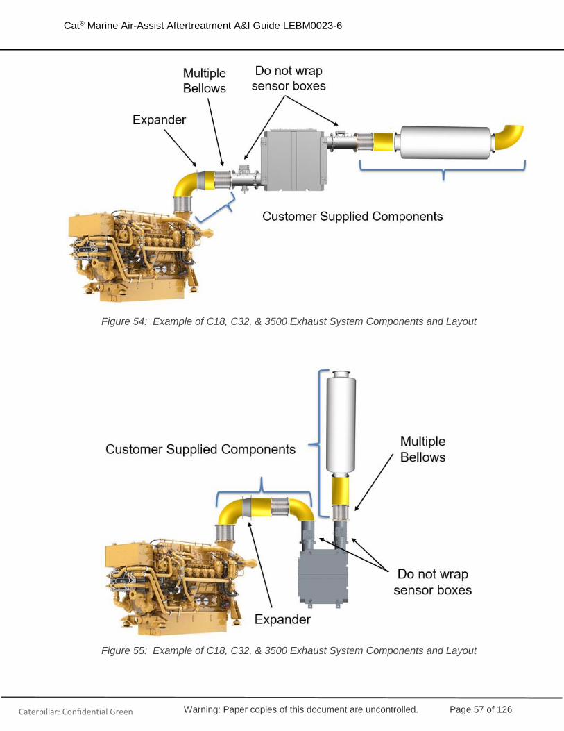
Warning: Paper copies of this document are uncontrolled. Page 57 of 126
Cat® Marine Air-Assist Aftertreatment A&I Guide LEBM0023-6
Caterpillar: Confidential Green
Figure 54: Example of C18, C32, & 3500 Exhaust System Components and Layout
Figure 55: Example of C18, C32, & 3500 Exhaust System Components and Layout

Warning: Paper copies of this document are uncontrolled. Page 58 of 126
Cat® Marine Air-Assist Aftertreatment A&I Guide LEBM0023-6
Caterpillar: Confidential Green
Figure 56: Example of C280 Exhaust System Components and Layout
Exhaust Backpressure Requirements
Because the CEM is a component of the exhaust system, it imposes backpressure on the engine. Therefore, its restriction must be considered when calculating the user allowance for backpressure. The data needed for each CEM restriction and total allowable restriction is provided in the System Data section of TMI & is linked to the engine performance number. Each engine rating may have a different backpressure allowance so TMI systems data should be referenced for this information. The pertinent TMI systems data includes the following three (3) items.
• MAXIMUM ALLOWABLE SYSTEM BACK PRESSURE – This provides the total allowable backpressure on the engine measured at the engine outlet. This would include the CEM, muffler, and any exhaust piping. This value can be found by looking up the engine’s performance data in TMI and navigating to the supplementary data section.
• MAXIMUM PRESSURE DROP ACROSS THE CEM – This provides the backpressure contribution from the CEM module. This value can be found by looking up the engine’s performance data in TMI and navigating to the supplementary data section.

Warning: Paper copies of this document are uncontrolled. Page 59 of 126
Cat® Marine Air-Assist Aftertreatment A&I Guide LEBM0023-6
Caterpillar: Confidential Green
• USER ALLOWANCE BACK PRESSURE – This provides the total backpressure allowance for the remaining vessel piping excluding the CEM. This value is calculated using the below equation and varies by rating.
The above exhaust restrictions are related by the below equation.
𝐌𝐀𝐗𝐈𝐌𝐔𝐌 𝐀𝐋𝐋𝐎𝐖𝐀𝐁𝐋𝐄 𝐒𝐘𝐒𝐓𝐄𝐌 𝐁𝐀𝐂𝐊 𝐏𝐑𝐄𝐒𝐒𝐔𝐑𝐄= 𝐌𝐀𝐗𝐈𝐌𝐔𝐌 𝐏𝐑𝐄𝐒𝐒𝐔𝐑𝐄 𝐃𝐑𝐎𝐏 𝐀𝐂𝐑𝐎𝐒𝐒 𝐓𝐇𝐄 𝐂𝐄𝐌 + 𝐔𝐒𝐄𝐑 𝐀𝐋𝐋𝐎𝐖𝐀𝐍𝐂𝐄 𝐁𝐀𝐂𝐊 𝐏𝐑𝐄𝐒𝐒𝐔𝐑𝐄
Refer to the Exhaust Systems A&I guide LEBW4970 for details on calculating and measuring exhaust backpressure of the total system. Refer to Product News LEXM0267 for Retrofit Ratings and Performance Numbers. Note: This information is not published in TMI for MaK products; consult the Order Execution or A&I Team for information.
Maximum Allowable
System Back Pressure Maximum Pressure Drop
Across the CEM User Allowance Back
Pressure
C32/3500 First Fit
Consult TMI: Varies by Rating
Consult TMI: Varies by Rating
27” H2O (6.7 kPa)
C280 First Fit 10” H2O (2.5 kPa)
C18/C32/3500 Retro Fit Consult TMI:
Varies by Rating
MaK Consult the MaK Order Execution Team
Table 21: Exhaust Backpressure
Examples Maximum Allowable
System Back Pressure Maximum Pressure Drop
Across the CEM User Allowance Back
Pressure
3516E First Fit 3386bhp / 2525bkW
EM1756 86” H2O (21.5 kPa) 59” H2O (14.8 kPa) 27” H2O (6.7 kPa)
3516E First Fit 2682bhp / 2000bkW
EM1766 65.6” H2O (16.3 kPa) 38.6” H2O (9.6 kPa) 27” H2O (6.7 kPa)
C280-12 First Fit 5444bhp / 4060bkW
EM0851 36” H2O (9 kPa) 26” H2O (6.5 kPa) 10” H2O (2.5 kPa)
C32 Retro Fit 1600bhp / 1193bkW
EM2768 40” H2O (10 kPa) 24” H2O (6 kPa) 16” H2O (4 kPa)
Table 22: Exhaust Backpressure Examples – Reference TMI for the most current information

Warning: Paper copies of this document are uncontrolled. Page 60 of 126
Cat® Marine Air-Assist Aftertreatment A&I Guide LEBM0023-6
Caterpillar: Confidential Green
Figure 57: 3500E & C32 EPA Tier 4 / IMO III Backpressure
Figure 58: C280 EPA Tier 4 & MaK Backpressure

Warning: Paper copies of this document are uncontrolled. Page 61 of 126
Cat® Marine Air-Assist Aftertreatment A&I Guide LEBM0023-6
Caterpillar: Confidential Green
Figure 59: C18, C32, & 3500C Retrofit Backpressure
Joint Loading
To minimize additional load on the exhaust flange, downstream exhaust piping must be self-supporting. A flexible joint should typically be installed to minimize cantilever type loads on the exhaust flange. Maximum allowable vertical load and bending moment limits are provided for each engine and rating in the Systems Data section of TMI. Dynamic loading for the CEM inlet and outlet can also be found for each engine rating in TMI. Refer to LEBW4970: Exhaust Systems as well as the Mounting and Thermal Growth sections of this document for more information.
Thermal Management and Protection
Care must be taken to ensure the exhaust temperature does not drop significantly between the engine and CEM inlet.
10% Load & Rated Speed
Maximum Allowable Temp Drop (Engine Outlet to CEM inlet)
C18 / C32 / 3500 10˚C
C280 / MaK 30˚C
Table 23: Maximum Temperature Drops from the Engine to the CEM

Warning: Paper copies of this document are uncontrolled. Page 62 of 126
Cat® Marine Air-Assist Aftertreatment A&I Guide LEBM0023-6
Caterpillar: Confidential Green
Exhaust piping between the engine outlet and CEM inlet must be insulated, except for the sensor boxes located on the CEM inlet and outlet as well as the sensor boxes on the mixing tube for C280 & MaK SCR system.. These sensor boxes must not be wrapped as the exhaust temperatures can lead to early failures of the sensors. The locations of these sensor boxes can be seen in Figure 60, Figure 61, Figure 62, and Figure 63 below. Caterpillar recommends thermally wrapping exhaust components to minimize ambient heat rejection and protect adjacent components from damage due to excessive temperatures. Additionally, refer to applicable marine society and SOLAS regulations which limit surface temperatures.
Figure 60: The two sensor boxes on the U-Flow and Z-Flow, shown in yellow, must NOT be wrapped with thermal insulation. (C18 / C32 / 3500 U-Flow)
Figure 61: The sensor box, shown in yellow, on the C280 / MaK Mixing Tube must NOT be wrapped with thermal insulation.

Warning: Paper copies of this document are uncontrolled. Page 63 of 126
Cat® Marine Air-Assist Aftertreatment A&I Guide LEBM0023-6
Caterpillar: Confidential Green
Figure 62: The sensor box, shown in yellow, on the C280 / MaK CEM inlet must NOT be wrapped with thermal insulation.
Figure 63: The sensor box, shown in yellow, on the C280 CEM outlet must NOT be wrapped with thermal insulation.
Sound Attenuation
The CEM provides some level of sound attenuation but is not designed to replace a muffler. A muffler will likely still be required on installations with aftertreatment systems. Refer to TMI Performance Data - Sound Data. The published information provides sound power levels after the CEM.

Warning: Paper copies of this document are uncontrolled. Page 64 of 126
Cat® Marine Air-Assist Aftertreatment A&I Guide LEBM0023-6
Caterpillar: Confidential Green
2.7 Overall System Considerations
Overall Mechanical Schematic
The below schematic highlights Caterpillar versus customer supplied mechanical connections of the overall aftertreatment system.
Figure 64: Overall System Schematic
The following components are REQUIRED unless noted: (1) Customer Supplied: Air Pressure Regulator: 724-1068 kPa (105-155 psi) (2) Customer or Caterpillar Supplied: Oil/Water Separator, Cat Option: 267-5286) (3) Customer Supplied: DEF Filter: 100µm (recommended) (4) Customer Supplied: Pressure Regulator: 34.5-69 kPa (5-10 psi) (5) Customer Supplied: Pressure Relief Valve: 69 kPa (10 psi) (6) Customer or Caterpillar Supplied: DEF Filter: 40µm, (Cat Option: 491-6779) (L1) Low Level Sensor: Required on the vessel DEF tank per EPA regulations. (L2) High Level Sensor
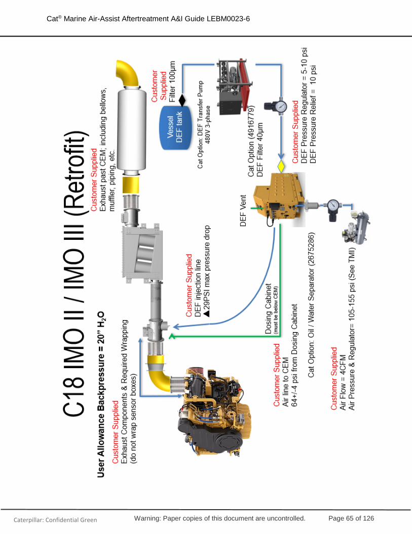
Warning: Paper copies of this document are uncontrolled. Page 65 of 126
Cat® Marine Air-Assist Aftertreatment A&I Guide LEBM0023-6
Caterpillar: Confidential Green

Warning: Paper copies of this document are uncontrolled. Page 66 of 126
Cat® Marine Air-Assist Aftertreatment A&I Guide LEBM0023-6
Caterpillar: Confidential Green
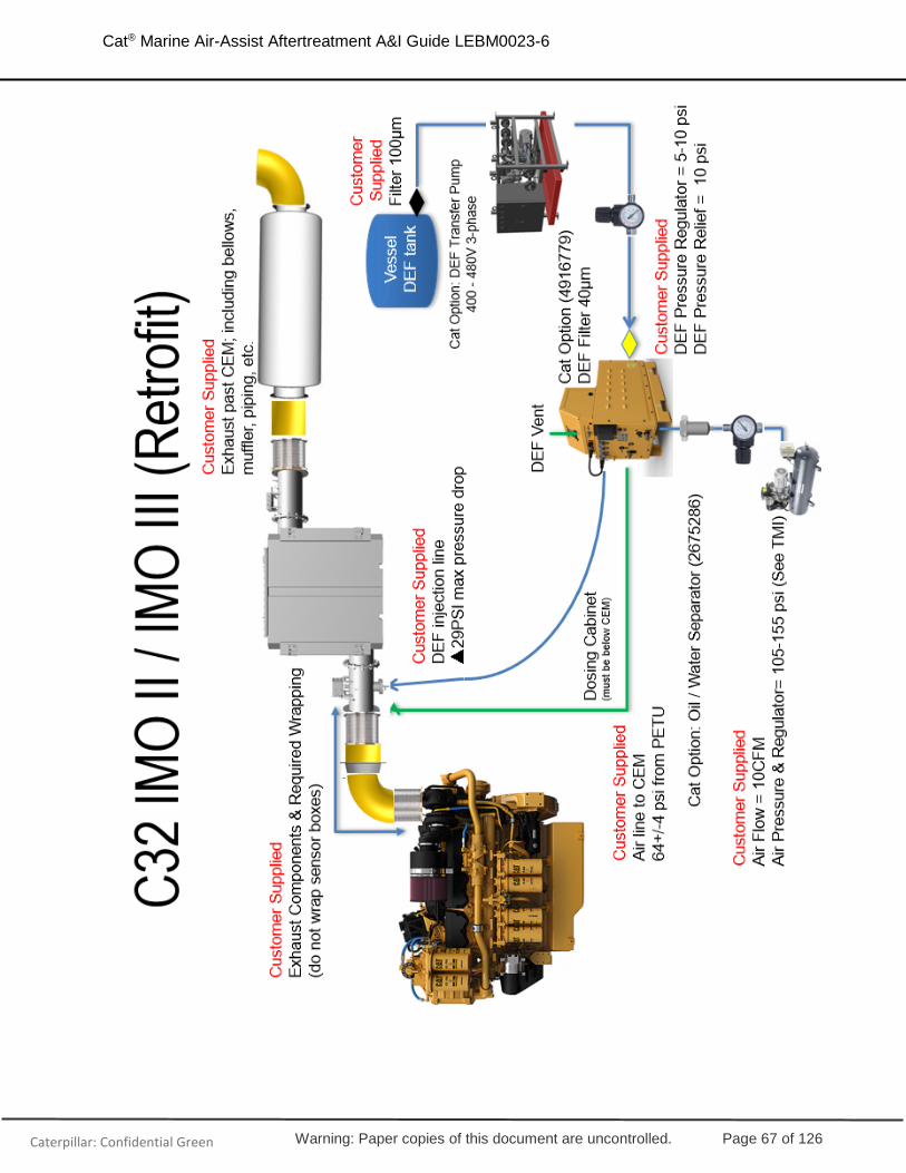
Warning: Paper copies of this document are uncontrolled. Page 67 of 126
Cat® Marine Air-Assist Aftertreatment A&I Guide LEBM0023-6
Caterpillar: Confidential Green

Warning: Paper copies of this document are uncontrolled. Page 68 of 126
Cat® Marine Air-Assist Aftertreatment A&I Guide LEBM0023-6
Caterpillar: Confidential Green

Warning: Paper copies of this document are uncontrolled. Page 69 of 126
Cat® Marine Air-Assist Aftertreatment A&I Guide LEBM0023-6
Caterpillar: Confidential Green

Warning: Paper copies of this document are uncontrolled. Page 70 of 126
Cat® Marine Air-Assist Aftertreatment A&I Guide LEBM0023-6
Caterpillar: Confidential Green

Warning: Paper copies of this document are uncontrolled. Page 71 of 126
Cat® Marine Air-Assist Aftertreatment A&I Guide LEBM0023-6
Caterpillar: Confidential Green

Warning: Paper copies of this document are uncontrolled. Page 72 of 126
Cat® Marine Air-Assist Aftertreatment A&I Guide LEBM0023-6
Caterpillar: Confidential Green

Warning: Paper copies of this document are uncontrolled. Page 73 of 126
Cat® Marine Air-Assist Aftertreatment A&I Guide LEBM0023-6
Caterpillar: Confidential Green

Warning: Paper copies of this document are uncontrolled. Page 74 of 126
Cat® Marine Air-Assist Aftertreatment A&I Guide LEBM0023-6
Caterpillar: Confidential Green

Warning: Paper copies of this document are uncontrolled. Page 75 of 126
Cat® Marine Air-Assist Aftertreatment A&I Guide LEBM0023-6
Caterpillar: Confidential Green

Warning: Paper copies of this document are uncontrolled. Page 76 of 126
Cat® Marine Air-Assist Aftertreatment A&I Guide LEBM0023-6
Caterpillar: Confidential Green

Warning: Paper copies of this document are uncontrolled. Page 77 of 126
Cat® Marine Air-Assist Aftertreatment A&I Guide LEBM0023-6
Caterpillar: Confidential Green

Warning: Paper copies of this document are uncontrolled. Page 78 of 126
Cat® Marine Air-Assist Aftertreatment A&I Guide LEBM0023-6
Caterpillar: Confidential Green

Warning: Paper copies of this document are uncontrolled. Page 79 of 126
Cat® Marine Air-Assist Aftertreatment A&I Guide LEBM0023-6
Caterpillar: Confidential Green
Welding
Welding of the CEM housing or mixing tube is strongly discouraged. It is permissible to add exhaust lagging pins to the reactor housing for insulation purposes. If welding is required, rods must be compatible with stainless steel, must not affect the thermal expansion movement of the CEM, or damage any electronics or sensors. Any failure due to improper welding will not be covered by warranty. Contact your Cat dealer prior to any welding.
Painting
Painting of the CEM is strongly discouraged. Skin temperatures of the CEM can reach as high as 525°C during operation and will cause charring and burning of the paint.
Multiple Engine Installations
Each engine requires its own dosing cabinet and CEM. (Refer to 2.2.1 and 2.2.2 for dosing cabinet sizes and mounting information.)
One transfer pump (if required) and one air compressor can be shared across multiple engines if sized correctly.
Depending on customer or regulatory requirements, some installations may require redundant DEF transfer pumps or air compressors. Two Cat DEF transfer pumps can be stacked and bolted to each other at the foot locations (refer to Figure 47 to see these locations.)

Warning: Paper copies of this document are uncontrolled. Page 80 of 126
Cat® Marine Air-Assist Aftertreatment A&I Guide LEBM0023-6
Caterpillar: Confidential Green
2.8 Mechanical Connection Summary
The below table summarizes the mechanical connections listed in this document.
Equipment Connection Fitting / Flange
Dosing Cabinet Service Tool Connector 9 Pin
Dosing Cabinet Wiring harness connector to engine ECM 23 Pin Connector
Dosing Cabinet Wiring harness connector to main DEF
tank (level sensor/transfer pump) 14 Pin Connector
Dosing Cabinet Wiring harness connector to CEM 21 Pin Connector
Dosing Cabinet DEF Vent Port ½” BARB
Dosing Cabinet AC Power In Grommet for wiring & 3 terminal Blocks
Dosing Cabinet
DEF Outlet to CEM 3/8” Quick Connect SAE J2044
(No. 6 STOR (Straight Thread O-Ring) if Quick Connect Removed)
Dosing Cabinet DEF Inlet 3/4-16” JIC
Dosing Cabinet Air Outlet to CEM No. 6 STOR (Straight Thread O-Ring)
Dosing Cabinet Air Inlet 9/16-18” JIC
Dosing Cabinet DC Power for Display 3 pin Connector
Injector DEF inlet line to CEM 3/4"-16 STOR
Injector Air inlet line to CEM 9/16”-18 JIC
C280 CEM 4x4x4 24” ANSI Class 150 Modified – ½” thickness
C280 CEM 5x5x4 24” ANSI Class 150 Modified – ½” thickness
C280 CEM 6x6x3 24” ANSI Class 150 Modified – ½” thickness
C280 Mixing Tube 4x4x4 18” ANSI Class 150 Modified – ½” thickness
C280 Mixing Tube 5x5x4 20” ANSI Class 150 Modified – ½” thickness
C280 Mixing Tube 6x6x3 20” ANSI Class 150 Modified – ½” thickness
Z-Flow & U-Flow 6-Brick 12” ANSI Class 150 Modified – ½” thickness
Z-Flow & U-Flow 12-Brick 14” ANSI Class 150 Modified – ½” thickness
Z-Flow & U-Flow 16-Brick 18” ANSI Class 150 Modified – ½” thickness
Z-Flow & U-Flow 20-Brick 20” ANSI Class 150 Modified – ½” thickness
Table 24: Mechanical Connection Summary
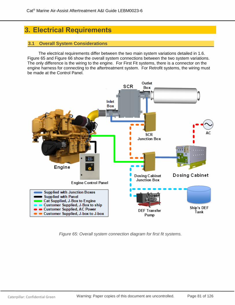
Warning: Paper copies of this document are uncontrolled. Page 81 of 126
Cat® Marine Air-Assist Aftertreatment A&I Guide LEBM0023-6
Caterpillar: Confidential Green
3. Electrical Requirements
3.1 Overall System Considerations
The electrical requirements differ between the two main system variations detailed in 1.6. Figure 65 and Figure 66 show the overall system connections between the two system variations. The only difference is the wiring to the engine. For First Fit systems, there is a connector on the engine harness for connecting to the aftertreatment system. For Retrofit systems, the wiring must be made at the Control Panel.
Figure 65: Overall system connection diagram for first fit systems.

Warning: Paper copies of this document are uncontrolled. Page 82 of 126
Cat® Marine Air-Assist Aftertreatment A&I Guide LEBM0023-6
Caterpillar: Confidential Green
Figure 66: Overall system connection diagram for retrofit systems.
3.2 Wiring Diagrams, Connectors and Pinouts
Wiring Diagrams
There are four main variations in wiring diagrams depending on:
• First fit or retrofit aftertreatment: First fit engines have a connection on the engine harness which is used for all aftertreatment connections while retrofit engines do not have this connection so all aftertreatment connections must be made at the control panel.
• Customer-supplier or panel-supplied power: Cat control panels provide a dedicated circuit breaker and keyswitch circuit for the aftertreatment which can be used. However, in some installations it may be preferred to use customer supplied power and keyswitch circuits.
Diagrams covering these four possible scenarios are shown below.

Warning: Paper copies of this document are uncontrolled. Page 83 of 126
Cat® Marine Air-Assist Aftertreatment A&I Guide LEBM0023-6
Caterpillar: Confidential Green
Figure 67: First fit, customer-supplied power.

Warning: Paper copies of this document are uncontrolled. Page 84 of 126
Cat® Marine Air-Assist Aftertreatment A&I Guide LEBM0023-6
Caterpillar: Confidential Green
Figure 68: First fit, panel-supplied power.
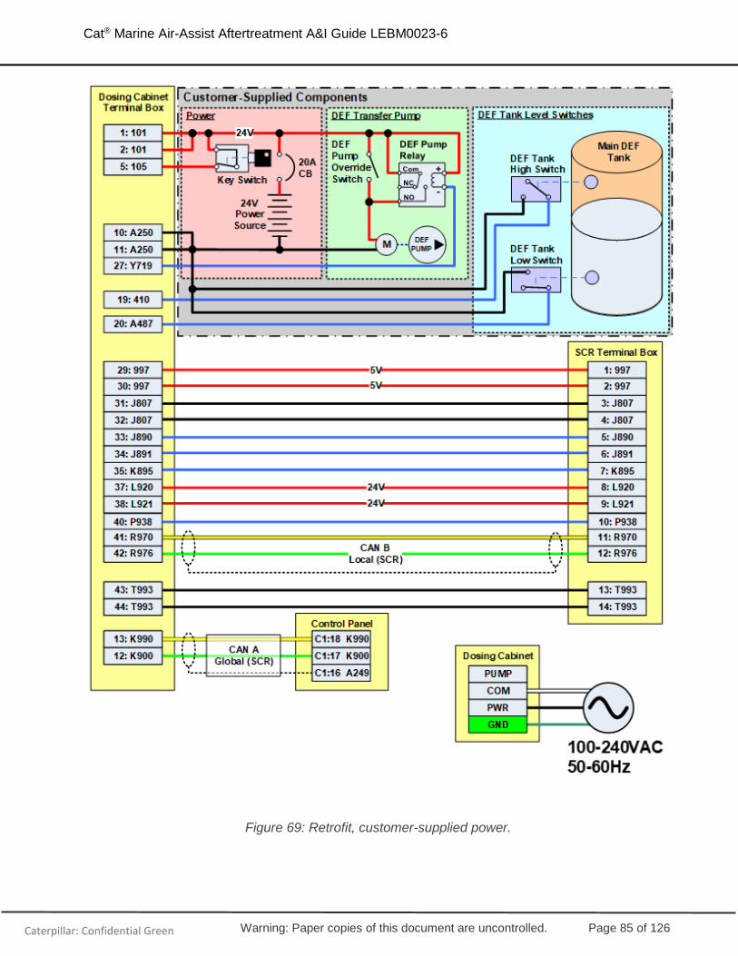
Warning: Paper copies of this document are uncontrolled. Page 85 of 126
Cat® Marine Air-Assist Aftertreatment A&I Guide LEBM0023-6
Caterpillar: Confidential Green
Figure 69: Retrofit, customer-supplied power.

Warning: Paper copies of this document are uncontrolled. Page 86 of 126
Cat® Marine Air-Assist Aftertreatment A&I Guide LEBM0023-6
Caterpillar: Confidential Green
Figure 70: Retrofit, panel-supplied power.

Warning: Paper copies of this document are uncontrolled. Page 87 of 126
Cat® Marine Air-Assist Aftertreatment A&I Guide LEBM0023-6
Caterpillar: Confidential Green
Connectors
First fit engines provide a connector for all aftertreatment connections on the engine. These connectors are shown in Figure 71 and Figure 72. All other connections are located on the terminal strips in the junction boxes and control boxes.
Figure 71: C18, C32, and 3500 aftertreatment connectors on engine.
Figure 72: C280 aftertreatment connectors on engine.
Retrofit engines do not have these engine connectors for the aftertreatment and the aftertreatment wiring connections can be made directly into connector C1 at the bottom of the panel using 8T-8730 sockets. This is shown in Figure 73.
Figure 73: Retrofit aftertreatment connections are made on the C1 connector on panel.

Warning: Paper copies of this document are uncontrolled. Page 88 of 126
Cat® Marine Air-Assist Aftertreatment A&I Guide LEBM0023-6
Caterpillar: Confidential Green
Pinouts
This section provides wiring information for each of the junction boxes. The pinouts are color-coded by destination and type for easy reference. The legend for this color coding is shown in Table 25.
Destination Description
Customer Supplied + VDC
SCR Terminal Box 0 VDC
Engine Connector Signal
Communications
Table 25: Pinout legend
Engine Connector – First Fit
Connector Pin ID Description Color Size Dosing Cabinet Terminal
B 945 CDL - BN 18 9
C 944 CDL + OR 18 8
J R976 Local CAN - GN 18 17
K R970 Local CAN + YL 18 16
P 101 System Power 24V RD 14 1
Q A250 System Power 0V BK 14 10
R 101 System Power 24V RD 14 2
S A250 System Power 0V BK 14 11
X 105 Keyswitch BR 18 5
Table 26: C18, C32, and 3500 first fit engine connector.
Connector Pin ID Description Color Size Dosing Cabinet Terminal
B 945 CDL - BN 18 9
C 944 CDL + OR 18 8
J R976 Local CAN - GN 18 17
K R970 Local CAN + YL 18 16
Q A250 System Power 0V BK 14 10
T 101 System Power 24V RD 14 1
V 101 System Power 24V RD 14 2
W A250 System Power 0V BK 14 11
X 105 Keyswitch BR 18 5
Table 27: C280 first fit engine connector.
Panel Connector – Retrofit
Control Panel ID Description Color Size Dosing Cabinet Terminal
C1:12 105 Keyswitch BR 18 5

Warning: Paper copies of this document are uncontrolled. Page 89 of 126
Cat® Marine Air-Assist Aftertreatment A&I Guide LEBM0023-6
Caterpillar: Confidential Green
C1:17 K900 Global CAN + YL 18 12
C1:18 K990 Global CAN - GN 18 13
C1:50 101 System Power 24V RD 14 1
C1:51 101 System Power 24V RD 14 2
C1:52 A250 System Power 0V BK 14 10
C1:53 A250 System Power 0V BK 14 11
Table 28: Retrofit panel connector.
Dosing Cabinet Terminal Box – First Fit
Terminal ID Description Color Size Destination
1 101 System Power 24V RD 14 Engine Connector pin P (C32), pin T (3500-C280)
2 101 System Power 24V RD 14 Engine Connector pin R (C32), pin V (3500-C280)
3 103 DEF Heater Relay 24V Not used
4 103 DEF Heater Relay 24V Not used
5 105 Keyswitch BR 18 Engine Connector pin X
6 229 DEF Heater Relay 0V Not used
7 229 DEF Heater Relay 0V Not used
8 944 CDL + OR 18 Engine Connector pin B
9 945 CDL - BN 18 Engine Connector pin C
10 A250 System Power 0V BK 14 Engine Connector pin Q
11 A250 System Power 0V BK 14 Engine Connector pin S (C32), pin W (3500-C280)
12 K900 Global CAN + Not used
13 K990 Global CAN - Not used
14 L838 DEF Heater Relay 24V Not used
15 P830 DEF Heater Relay 0V Not used
16 R970 Local CAN + YL 18 Engine Connector pin K
17 R976 Local CAN - GN 18 Engine Connector pin J
18 Y719 DEF Transfer Pump Switch
Not used
19 410 Ship's DEF Tank Hi Switch
WH 18 DEF Tank Hi Switch
20 A487 Ship's DEF Tank Lo Switch
PU 18 DEF Tank Lo Switch
21 H857 Local DEF Tank Level Sensor
Not used
22 K811 Local DEF Tank Temp Sensor
Not used
23 K839 DEF Heater Relay 24V Not used
24 L838 DEF Line Heater 0V Not used
25 P830 DEF Line Heater 24V Not used

Warning: Paper copies of this document are uncontrolled. Page 90 of 126
Cat® Marine Air-Assist Aftertreatment A&I Guide LEBM0023-6
Caterpillar: Confidential Green
26 T791 DEF Heater Relay 0V Not used
27 Y719 DEF Transfer Pump Switch
BU 18 DEF Pump Relay Coil -
28 Y947 Analog Sensor Return Not used
29 997 5V Analog Sensor Power OR 18 SCR Terminal Box terminal 1
30 997 5V Analog Sensor Power OR 18 SCR Terminal Box terminal 2
31 J807 Dout Return BK 18 SCR Terminal Box terminal 3
32 J807 Dout Return BK 18 SCR Terminal Box terminal 4
33 J890 SCR Inlet Gas Temp BU 18 SCR Terminal Box terminal 5
34 J891 SCR Outlet Gas Temp GN 18 SCR Terminal Box terminal 6
35 K895 Aft #1 Module ID BU 18 SCR Terminal Box terminal 7
36 L838 DEF Line Heater 0V Not used
37 L920 Intake NOx Sensor 24V BR 18 SCR Terminal Box terminal 8
38 L921 Outlet NOx Sensor 24V YL 18 SCR Terminal Box terminal 9
39 P830 DEF Line Heater 24V Not used
40 P938 SCR Abs Pressure WH 18 SCR Terminal Box terminal 10
41 R970 Local CAN + YL 18 SCR Terminal Box terminal 11
42 R976 Local CAN - GN 18 SCR Terminal Box terminal 12
43 T993 Analog Sensor Return BR 18 SCR Terminal Box terminal 13
44 T993 Analog Sensor Return BR 18 SCR Terminal Box terminal 14
Table 29: First fit Dosing Cabinet Terminal Box
Dosing Cabinet Terminal Box – Retrofit
Terminal ID Description Color Size Destination
1 101 System Power 24V RD 14 Control Panel C1:50
2 101 System Power 24V RD 14 Control Panel C1:51
3 103 DEF Heater Relay 24V Not used
4 103 DEF Heater Relay 24V Not used
5 105 Keyswitch BR 18 Control Panel C1:12
6 229 DEF Heater Relay 0V Not used
7 229 DEF Heater Relay 0V Not used
8 944 CDL + Not Used
9 945 CDL - Not Used
10 A250 System Power 0V BK 14 Control Panel C1:52
11 A250 System Power 0V BK 14 Control Panel C1:53
12 K900 Global CAN + YL 18 Control Panel C1:17
13 K990 Global CAN - GN 18 Control Panel C1:18
14 L838 DEF Heater Relay 24V Not used
15 P830 DEF Heater Relay 0V Not used
16 R970 Local CAN + Not used
17 R976 Local CAN - Not used
18 Y719 DEF Transfer Pump Switch Not used
19 410 Ship's DEF Tank Hi Switch WH 18 DEF Tank Hi Switch
20 A487 Ship's DEF Tank Lo Switch PU 18 DEF Tank Lo Switch

Warning: Paper copies of this document are uncontrolled. Page 91 of 126
Cat® Marine Air-Assist Aftertreatment A&I Guide LEBM0023-6
Caterpillar: Confidential Green
21 H857 Local DEF Tank Level Sensor
Not used
22 K811 Local DEF Tank Temp Sensor
Not used
23 K839 DEF Heater Relay 24V Not used
24 L838 DEF Line Heater 0V Not used
25 P830 DEF Line Heater 24V Not used
26 T791 DEF Heater Relay 0V Not used
27 Y719 DEF Transfer Pump Switch BU 18 DEF Pump Relay Coil -
28 Y947 Analog Sensor Return Not used
29 997 5V Analog Sensor Power OR 18 SCR Terminal Box terminal 1
30 997 5V Analog Sensor Power OR 18 SCR Terminal Box terminal 2
31 J807 Dout Return BK 18 SCR Terminal Box terminal 3
32 J807 Dout Return BK 18 SCR Terminal Box terminal 4
33 J890 SCR Inlet Gas Temp BU 18 SCR Terminal Box terminal 5
34 J891 SCR Outlet Gas Temp GN 18 SCR Terminal Box terminal 6
35 K895 Aft #1 Module ID BU 18 SCR Terminal Box terminal 7
36 L838 DEF Line Heater 0V Not used
37 L920 Intake NOx Sensor 24V BR 18 SCR Terminal Box terminal 8
38 L921 Outlet NOx Sensor 24V YL 18 SCR Terminal Box terminal 9
39 P830 DEF Line Heater 24V Not used
40 P938 SCR Abs Pressure WH 18 SCR Terminal Box terminal 10
41 R970 Local CAN + YL 18 SCR Terminal Box terminal 11
42 R976 Local CAN - GN 18 SCR Terminal Box terminal 12
43 T993 Analog Sensor Return BR 18 SCR Terminal Box terminal 13
44 T993 Analog Sensor Return BR 18 SCR Terminal Box terminal 14
Table 30: Retrofit Dosing Cabinet Terminal Box.
CEM Terminal Box – First Fit and Retrofit
CEM Terminal ID Description Color Size Dosing Cabinet Terminal
1 997 5V Analog Sensor Power OR 18 29
2 997 5V Analog Sensor Power OR 18 30
3 J807 Dout Return BK 18 31
4 J807 Dout Return BK 18 32
5 J890 SCR Inlet Gas Temp BU 18 33
6 J891 SCR Outlet Gas Temp GN 18 34
7 K895 Aft #1 Module ID BU 18 35
8 L920 Intake NOx Sensor 24V BR 18 37
9 L921 Outlet NOx Sensor 24V YL 18 38
10 P938 SCR Abs Pressure WH 18 40
11 R970 Local CAN + YL 18 41
12 R976 Local CAN - GN 18 42
13 T993 Analog Sensor Return BR 18 43
14 T993 Analog Sensor Return BR 18 44
Table 31: First Fit and Retrofit CEM Terminal Box

Warning: Paper copies of this document are uncontrolled. Page 92 of 126
Cat® Marine Air-Assist Aftertreatment A&I Guide LEBM0023-6
Caterpillar: Confidential Green
3.3 CDL and J1939 Control Wiring
CDL (First Fit Only)
Use twisted pair wires to connect the CDL wiring between the Dosing Cabinet Terminal Box and the Engine Connector as shown in Figure 74. First Fit systems transmit aftertreatment parameters over CDL to the engine ECM, which re-broadcasts them over the J1939 Global Data Link to the Control Panel and Remote Displays. This CDL connection cannot be used on retrofit systems.
Figure 74: CDL connection on first fit systems.
J1939
J1939 Architecture
The J1939 communication bus length must not exceed 40 meters with a max drop to each device of 1 meter. The bus is terminated at each end by 120 ohm resistors.
Figure 75: J1939 Architecture limits
If the vessel does not allow for the standard 40 meter bus, two separate busses can be connection using a J1939 repeater (available on the internet).
120 ΩResistor
120 ΩResistor
1 meter max
Device
Device Device
40 meters max

Warning: Paper copies of this document are uncontrolled. Page 93 of 126
Cat® Marine Air-Assist Aftertreatment A&I Guide LEBM0023-6
Caterpillar: Confidential Green
Figure 76: J1939 Repeater
First Fit Systems
Use approved J1939 cable to wire between the Dosing Cabinet Terminal Box and the SCR Terminal Box as shown in Figure 77. When using a Cat control panel, Cat engine and Cat aftertreatment system, there will be one (1) excess terminating resistor on CAN B Local (SCR) once the components are connected. The terminating resistor next to the engine ECM must be removed as shown in Figure 78.
Figure 77: J1939 connection on first fit systems.
120 ΩResistor
120 ΩResistor
1 meter max
Device
Device Device
40 meters max
J1939 Repeater
1 meter max
120 ΩResistor
120 ΩResistor
1 meter max
Device
Device Device
40 meters max
1 meter max

Warning: Paper copies of this document are uncontrolled. Page 94 of 126
Cat® Marine Air-Assist Aftertreatment A&I Guide LEBM0023-6
Caterpillar: Confidential Green
Figure 78: J1939 diagram for first fit systems showing removed terminating resistor.
Retrofit Systems
Use approved J1939 cable to wire between the Dosing Cabinet Terminal Box and the SCR Terminal Box as shown in
Figure 79. When using a Cat control panel, Cat engine and Cat aftertreatment system, there will be three (3) excess terminating resistors on CAN A Global once the components are connected. Remove one (1) terminating resistor from the Control Panel and the two (2) from the lower portion of the Dosing Cabinet as shown in Figure 80.
Figure 79: J1939 connection on retrofit systems.

Warning: Paper copies of this document are uncontrolled. Page 95 of 126
Cat® Marine Air-Assist Aftertreatment A&I Guide LEBM0023-6
Caterpillar: Confidential Green
Figure 80: J1939 diagram for retrofit systems showing removed terminating resistors.
J1939 Bus Parameters
Parameter Name PGN SPN First Fit 3516E Retrofit
Aftertreatment 1 SCR System State 61475 4332 Y Y
Aftertreatment 1 SCR Intake Temp 64830 4360 Y Y
Aftertreatment 1 SCR Outlet Temp 64830 4363 Y Y
Aftertreatment 1 SCR Intake Pressure 64831 6586 Y Y
Aftertreatment 1 Supply Air Pressure 64927 3485 Y Y
Aftertreatment 1 DEF Doser Pressure 64590 6875 Y Y
Aftertreatment 1 DEF Quick Thaw Temp 64829 4368 Y Y
Aftertreatment 1 DEF Doser 1 Temp 64833 4337 Y N
Aftertreatment 1 DEF Quick Thaw Tank Volume 64829 4367 Y Y
Aftertreatment 1 SCR Dosing Air Assist Valve 64833 4336 Y Y
Aftertreatment 1 DEF Dosing Unit 1 Diverter Valve 64828 4376 Y Y
Aftertreatment 1 DEF Tank Fill Valve Command 64828 5434 Y Y
Aftertreatment 1 DEF Pump Drive Percentage 64828 4375 Y Y
Aftertreatment 1 Total DEF Used 64701 5963 Y Y
Aftertreatment 1 SCR System Hydrocarbon 64514 7934 Y Y
Aftertreatment System Enable Status 33024 7851 Y Y
Aftertreatment System Enable Command 34048 8148 Y Y
Total Aftertreatment Operating Hour 64585 8629 N Y
Aftertreatment DEF Dosing Mode Command 64561 9175 Y N

Warning: Paper copies of this document are uncontrolled. Page 96 of 126
Cat® Marine Air-Assist Aftertreatment A&I Guide LEBM0023-6
Caterpillar: Confidential Green
Aftertreatment DEF Dosing Mode Status 64980 9176 Y N
Aftertreatment 2 SCR Intake Temp 64824 4413 Y (C280 only) N
Aftertreatment 2 SCR Outlet Temp 64824 4415 Y (C280 only) N
Aftertreatment 2 SCR Intake Pressure 64825 6587 Y (C280 only) N
Aftertreatment 2 Supply Air Pressure 64926 3499 Y (C280 only) N
Aftertreatment 2 DEF Doser Pressure 64589 6876 Y (C280 only) N
Aftertreatment 2 DEF Quick Thaw Temp 64820 4434 Y (C280 only) N
Aftertreatment 2 DEF Doser 1 Temp 64827 4390 Y (C280 only) N
Aftertreatment 2 DEF Quick Thaw Tank Volume 64820 4433 Y (C280 only) N
DEF Quality Malfunction Time ++ 64599 6818 Y N
Aftertreatment 1 SCR Intake High Temp Time++ 64487 8327 Y N
DEF Tank1 Empty Time++ 64599 6817 Y N
Engine speed 61444 190 Y Y
Boost Pressure 65270 102 Y Y
Boost Temp (IMT) 65270 105 Y Y
Fuel Rate 64737 1600 Y Y
Barometric Pressure 65269 108 Y Y
J1939 Diagnostics
In addition to the parameters listed above, the following SPNs can be transmitted as diagnostic messages (DM1).
Parameter Name SPN
Number of ECU Resets 152
Battery Potential / Power Input #1 168
Ambient Air Temperature 171
Engine Exhaust Gas Temperature 173
Calibration Memory 630
Calibration Module 631
J1939 Network #1 639
Heater Circuit #1 854
J1939 Network #2 1231
Aftertreatment #1 DEF Tank Volume #1 1761
Engine Exhaust Manifold Bank #1 Temperature #1 2434
Aftertreatment #1 Intake NOx 3216
Aftertreatment #1 Intake O2 3217
Aftertreatment #1 Outlet NOx 3226
Aftertreatment #1 Outlet O2 3227
Aftertreatment #2 Outlet NOx 3265
Aftertreatment #2 Outlet %O2 3266
Aftertreatment #1 DEF Controller 3360
Aftertreatment #1 DEF Dosing Unit Input Lines 3362
Sensor Supply Voltage 1 3509
Sensor Supply Voltage 2 3510

Warning: Paper copies of this document are uncontrolled. Page 97 of 126
Cat® Marine Air-Assist Aftertreatment A&I Guide LEBM0023-6
Caterpillar: Confidential Green
Aftertreatment #1 DEF Concentration 3516
Aftertreatment #1 SCR Dosing Air Assist Absolute Pressure 4335
Aftertreatment #1 DEF Line Heater #3 4356
Aftertreatment #1 DEF Line Heater #4 4357
Aftertreatment #1 SCR Catalyst Conversion Efficiency 4364
Aftertreatment #1 DEF Quick Thaw Heater 4372
Aftertreatment #1 DEF Line Heater Relay 5491
Aftertreatment #1 Identification 5576
Aftertreatment #1 DEF Pump Heater 5706
Aftertreatment #1 Intake Gas Sensor Power Supply 5758
Aftertreatment #1 Outlet Gas Sensor Power Supply 5759
Aftertreatment #2 Outlet Gas Sensor Power Supply 5761
Aftertreatment #1 SCR Intake Absolute Pressure 6797
ECU Interface Mismatch 6806
Aftertreatment #1 DEF Line Heater Relay #2 7069
Aftertreatment #1 Inconsistent Configuration Detected 7105
Aftertreatment #1 DEF Pump 7107
Aftertreatment #1 DEF Pump Power Relay 7416
Aftertreatment #1 DEF Control Module Circuit Breaker 7417
Aftertreatment #1 SCR System Sulfation Level 7504
3.4 24V Power Supply
Customer Supplied
A 24VDC power supply is required for the aftertreatment system. A 20-amp circuit breaker is recommended for proper operation of the system. A Keyswitch is recommended, the same Keyswitch must be used for the engine and its aftertreatment system. If different Keyswitches are used, a mismatch in the state of the different switches can cause the aftertreatment system to be inoperable while the engine is running.
Figure 81: Power supply diagram with customer supplied power.

Warning: Paper copies of this document are uncontrolled. Page 98 of 126
Cat® Marine Air-Assist Aftertreatment A&I Guide LEBM0023-6
Caterpillar: Confidential Green
Engine or Panel Supplied
If a factory MECP, MGCP II, or IIIB panel is installed, a circuit breaker is available specifically for the Aftertreatment System. There is an aftertreatment circuit breaker in the power distribution box for the 3500E and C280.
Engine Supplied - First Fit
The 24VDC power supply is connected to the engine connector. Depending on the distance between the engine and the aftertreatment system, a 20A circuit breaker may be desired. A Keyswitch is recommended. Operation of the Keyswitch during normal operation will reset the AFT ECM faults. It will not stop DEF dosing if the engine is already running. It will not stop a purge cycle.
Figure 82: Power supply diagram with panel supplied power on first fit applications.
Panel Supplied - Retrofit
The 24VDC power supply is connected to the C1 connector on the bottom of the control panel. Depending on the distance between the engine and the aftertreatment system, a 20A circuit breaker may be desired. A Keyswitch is recommended. Operation of the Keyswitch during normal operation will reset the AFT ECM faults. It will not stop DEF dosing if the engine is already running. It will not stop a purge cycle.
Figure 83: Power supply diagram with panel supplied power on retrofit applications.

Warning: Paper copies of this document are uncontrolled. Page 99 of 126
Cat® Marine Air-Assist Aftertreatment A&I Guide LEBM0023-6
Caterpillar: Confidential Green
3.5 AC Power Supply
The AC power connections are inside the Dosing Cabinet. They can be accessed by removing either the top or side panel. The terminal strip is marked COM for the white neutral wire, PWR for the black live wire, and GND for the green ground wire. The AC connection can be anywhere between 100 and 240 volts AC, at 50 or 60 Hertz.
Figure 84: Dosing Cabinet AC power requirements
Figure 85: Dosing Cabinet AC power requirements.
NOTE: If using a GFI outlet make sure it meets all the requirements and it is not tied with any other circuits as the load from dosing pump could cause the GFI outlet to trip.

Warning: Paper copies of this document are uncontrolled. Page 100 of 126
Cat® Marine Air-Assist Aftertreatment A&I Guide LEBM0023-6
Caterpillar: Confidential Green
3.6 DEF Transfer Pump Control
The Cat supplied DEF transfer pump or a 3rd party supplied pump can be used. The control of this pump by the aftertreatment ECM is the same regardless of source. When the local tank level in the Dosing Cabinet is low, the Dosing Cabinet will send a signal on terminals 27 and 18 (0V = active) to activate the DEF Transfer Pump Relay. It will also open the local Dosing Cabinet tank’s Fill Valve. A DEF Transfer Pump Override Switch can be installed if desired as shown in Figure 86. The configuration shown in Figure 86 uses the same 24V power supply as the Dosing Cabinet. If the DEF Transfer Pump requires a different voltage, it must be wired independently as shown in Figure 87. The DEF Pump Relay will still be powered by the Dosing Cabinet 24V and controlled by the signal on terminal 27 but the DEF Transfer Pump and DEF Pump Override Switch will be connected to the independent power source.
Figure 86: DEF transfer pump control with a common power source and DEF pump override switch.
Figure 87: DEF transfer pump control with an independent power source.

Warning: Paper copies of this document are uncontrolled. Page 101 of 126
Cat® Marine Air-Assist Aftertreatment A&I Guide LEBM0023-6
Caterpillar: Confidential Green
A DEF pump relay should be used even if a common power supply is used and sized appropriately for the pump. An override switch is recommended in to troubleshoot and in case of relay issues.
DEF Transfer Pump Control with Multiple Dosing Cabinets
It is possible to supply more than one engine with DEF with a single DEF transfer pump. If multiple Dosing Cabinets are connected to a single transfer pump, they can all activate the pump relay in parallel – this will not damage the ECM or cause an alarm. As shown in Figure 88, either Dosing Cabinet can activate the pump relay, but only the Dosing Cabinet that needs DEF will open its local fill solenoid.
Figure 88: Example of installation with DEF transfer pump and multiple Dosing Cabinets.
NOTE: The dosing cabinets shown above are for reference only, any number and combination Cat Dosing Cabinets may be connected in parallel as shown.

Warning: Paper copies of this document are uncontrolled. Page 102 of 126
Cat® Marine Air-Assist Aftertreatment A&I Guide LEBM0023-6
Caterpillar: Confidential Green
3.7 Main DEF Tank Level Switches
The ship’s main DEF tank level can be monitored by the Dosing Cabinet. If the “Tank High” or “Tank Low” switches are activated and connected to our system, the Dosing Cabinet ECM will broadcast an alarm on the J1939 bus. The alarm will be displayed by the Local control panel or display. If the dosing cabinets are being used to monitor main DEF tanks levels, it is recommended that at least two Dosing Cabinets from different engines (e.g. one propulsion engine, one generator set) be connected so the main DEF tank is always monitored, even if one engine or Dosing Cabinet is powered down. Both switches must be wired to be open during normal operation. The Dosing Cabinet should be connected to the low switch’s “common” and “normally closed” terminals (during normal operation, the float will open the switch). The Dosing Cabinet should also be connected to the high switch’s “common” and “normally open” terminals (the float will close the switch when the tank is high).
Figure 89: Main DEF tank level switches
3.8 Electrical Loads
Electrical loads for various aftertreatment components are provided in Table 32.
SCR Component Electrical Load
AC Max Amp DC Max Amp
3 3.9
Table 32: Aftertreatment system electrical loads.

Warning: Paper copies of this document are uncontrolled. Page 103 of 126
Cat® Marine Air-Assist Aftertreatment A&I Guide LEBM0023-6
Caterpillar: Confidential Green
3.9 Temperature Limits
The electrical sensors and wires on the CEM / Missing Tube have temperature limits that must be considered during the installation. Although the CEM must be insulated, the spools are already insulated from the factory. This insulation must be inspected, but no additional insulation should be installed. The sensor boxes and wiring must be open to air flow, as seen in Figure 90, and kept below the temperatures shown in Table 33. The wiring from the sensors must also be tied so that its weight doesn’t pull on the sensors once they’re installed.
Figure 90: Sensor Box
Component Temperature Limits
Component Temp Limit (C)
Temperature Sensors 120
NOx Sensor Control Box 100
Pressure Sensor 125
NOx Sensor Wire (from Probe end to Control Box)
200
Table 33: Electrical Component Temperature Limits

Warning: Paper copies of this document are uncontrolled. Page 104 of 126
Cat® Marine Air-Assist Aftertreatment A&I Guide LEBM0023-6
Caterpillar: Confidential Green
Figure 91 and Figure 92 show the locations of the 5 sensors on the spools. The pressure sensor may or may not be within the sensor box.
Figure 91: U-Flow / Z-Flow Inlet Spool Sensors (with sensor control box removed)
Figure 92: U-Flow / Z-Flow Outlet Spool Sensors

Warning: Paper copies of this document are uncontrolled. Page 105 of 126
Cat® Marine Air-Assist Aftertreatment A&I Guide LEBM0023-6
Caterpillar: Confidential Green
4. Service and Maintenance Considerations
4.1 Cleaning
High Pressure Wash
High pressure air and/or water may be used on the CEM and Dosing cabinet for cleaning purposes. The maximum allowable pressure for each is given in Table 34. Avoid spraying water directly on electrical connectors, connections, and components. Caution should always be exercised when using high pressure fluid and it can cause fluid and/or debris to be ejected. Always wear necessary personal protective equipment when cleaning components.
Fluid Maximum Pressure
Air 205 kPa (30 psi)
Water 275 kPa (40 psi)
Table 34: Allowable pressure for high pressure wash of aftertreatment components.
Wiring harness connector seals may experience failures if impacted directly with high pressure water. It is recommended to avoid direct exposure to these seals and, where not possible, install shielding to protect the connector.
Spills & Basic Cleaning
Any spills or leaks should be cleaned up immediately by wiping them clean and rinsing the area with water. Any DEF spilled onto hot components may cause harmful vapors. Care must be taken while dispensing DEF. Do not use containers or funnels that have been used with other materials previously as this may cause contamination.
HC Mitigation & EPA Codes
Refer to Engine Specific OMMs for HC Mitigation & EPA code details: SEBU9045 – C18
M0078454 – C32 M0065584 – 3500E SEBU9211 – C280-12 SEBU9351 – C280-16
Warning: Paper copies of this document are uncontrolled. Page 106 of 126
Cat® Marine Air-Assist Aftertreatment A&I Guide LEBM0023-6
Caterpillar: Confidential Green
5. Startup and Commissioning
5.1 Initial Startup
Refer to LEBM0088 Aftertreatment Initial Start-Up and Commissioning Guide Refer to LEBM0047 Start Up checklist for the SCR system Refer to Engine Specific OMMs: SEBU9045 – C18
M0078454 – C32 M0065584 – 3500E SEBU9211 – C280-12 SEBU9351 – C280-16
5.2 Commissioning
Refer to LEBM0088 Aftertreatment Initial Start-Up and Commissioning Guide Refer to LEBM0025 Marine Commissioning Guide
Delegated Final Assembly (DFA)
(1) Each installer shall enter into a delegated final assembly agreement (DFA) with Caterpillar, Inc.
as required by 40 C.F.R. § 1068.261. This publication fulfills Cat’s obligation under 40 C.F.R. §
1068.261 (c) (2) to provide installation instructions to ensure the engine will be installed in its
certified configuration. Refer to LEXM0281 (Product News: DFA Checklist) and LEDM0153
(A&I Newsletter: Marine DFA for EPA Tier 4 and IMO III)).
a. All aftertreatment systems (EPA and IMO III) must be documented in the DFA web
portal.
(2) The installer is required to follow Cat Application and Installation requirements for proper Cat
CEM integration with the engine.
(3) A full sea trial, as described in the marine commissioning procedure (LEBM0025), utilizing
CAMPAR, is required on all engines equipped with an SCR system. The completed sea trial
data must be uploaded by the authorized Cat dealer in Service Interlink. The following forms
must also be completed and uploaded into Service Interlink:
a. Design and Construction Review Form (SEHS8716)
b. Start Up checklist for the Engine:
i. LEBM0038 for C7-C32 Prop
ii. LEBM0039 for 3500-C280 Prop
iii. LEBM0053 for C7-C32 Aux
iv. LEBM0057 for 3500-C280 Aux
c. Start Up checklist for the SCR system (LEBM0047)
Any deviation from these instructions resulting in improper installation or connection of the Cat SCR system may be considered an emissions-related defect requiring the shipyard or installer to report to U.S. EPA pursuant to 40 C.F.R. § 1068.261 (h). Shipyard installations are subject to audit by Cat pursuant to 40 C.F.R. § 1068.261 (d)(3), as further set forth in the delegated final assembly agreement.

Warning: Paper copies of this document are uncontrolled. Page 107 of 126
Cat® Marine Air-Assist Aftertreatment A&I Guide LEBM0023-6
Caterpillar: Confidential Green
Note: If the available Cat CEM option does not meet the application/installation requirements, the installer must contact his or her respective Caterpillar A&I Representative.
Cat Engine ET Configuration
Cat ET
Connect Cat ET to the engine service tool connector.
Verifying Current Software Revision
Using the Dosing Cabinet software number listed in Cat ET, open SIS and verify that this is still the latest software part number. (If an update is made later, all parameters that have been configured will remain configured after the software update.)
Enabling Aftertreatment System
If it is not already enabled, change the Aftertreatment System Enable Status to Enabled.

Warning: Paper copies of this document are uncontrolled. Page 108 of 126
Cat® Marine Air-Assist Aftertreatment A&I Guide LEBM0023-6
Caterpillar: Confidential Green
Labeling Dosing Cabinet Disconnect Switches
It is recommended to label the Dosing Cabinet power disconnect switches with a warning:
Warning: Do not disconnect power to the Aftertreatment System unless the System State = “Dormant” or “Ready for Shutdown”
(System State is shown on the Local Control Panel or Display.) Parameters are saved once per hour into flash memory, disconnecting power when the system is not ready will cause data to be lost. The Dosing Cabinet must not be powered down during a Purge cycle, it will cause alarms and can lead to crystallized DEF in unpurged lines.
ECM ID and Serial Numbers
In the Dosing Cabinet ECM configuration in Cat ET, there are three ID numbers: Engine ECM S/N, Aftertreatment ID, and the Dosing Cabinet ID (Aftertreatment DEF Pump Electronics Tank Unit ID).
Program Engine ECM Serial Number
The Dosing Cabinet must be programmed with the Engine ECM Serial Number for the proper reporting in the Product Status Report.

Warning: Paper copies of this document are uncontrolled. Page 109 of 126
Cat® Marine Air-Assist Aftertreatment A&I Guide LEBM0023-6
Caterpillar: Confidential Green
Aftertreatment ID
Cat ET will auto-populate the field for the Aftertreatment ID based on the information it receives from the ID module mounted in the CEM electronics box.
Program Dosing Cabinet ID
The Dosing Cabinet ECM ID (Aftertreatment DEF Pump Electronics Tank Unit ID) must be programmed to match the ID of the Aftertreatment ID in the CEM connected to the Dosing Cabinet.

Warning: Paper copies of this document are uncontrolled. Page 110 of 126
Cat® Marine Air-Assist Aftertreatment A&I Guide LEBM0023-6
Caterpillar: Confidential Green
Program Engine Location
The Engine Location must also be configured.
Control Panel Configuration
There are three options for control panels.
Cat Panel – Aftertreatment Supported
This currently includes the LECP 2, LECP 3, MECP II, MECP IIIb, MGCP II and MGCP IIIb. (The RP410E supports aftertreatment when used with one of these panels.)
Cat Panel – Aftertreatment Not Supported
This currently includes the EMCP 4.2, DEIF, MECP I, MPD, and CMPD local control panels and the CMD helm display. Some of these displays (EMCP 4.2, DEIF, MECP I and CMD) will be updated to support Caterpillar supplied aftertreatment systems in the future but they do not currently support it. A third-party display is required to display parameters and alarms, and to control the aftertreatment system.
Cat Retrofit Aftertreatment Dosing Cabinet with Local Display
This option can be used in conjunction with either of the previous two options. The local display on the dosing cabinet will display aftertreatment parameters and alarms (which can also be monitored by other panels). It will also control the aftertreatment system (enable/disable) and the dosing mode (IMO II/III – airless systems only). In this case, the local display will be the only method of controlling the aftertreatment

Warning: Paper copies of this document are uncontrolled. Page 111 of 126
Cat® Marine Air-Assist Aftertreatment A&I Guide LEBM0023-6
Caterpillar: Confidential Green
system, no other device is allowed to take control. Since the control commands are continuously broadcast over J1939, a second device broadcasting contrary commands would prevent the system from operating correctly. If a Retrofit Cabinet with Local Display is installed, the local control panel must be configured to NOT broadcast control parameters. However, it can still be configured to display status parameters and alarms if desired.
Cat Panel Configuration (Aftertreatment Supported)
When using a Cat MECP/MGCP II or III panel, download the latest zip file containing factory default configurations from SIS, they contain the required configuration items to support a Cat aftertreatment system. If a manual configuration is required, follow the steps below.
Manual Configuration
Connect a laptop to the DCU as shown in the Programming Guide. You should see the screen below.
Select DCU, User Interface, Controls.

Warning: Paper copies of this document are uncontrolled. Page 112 of 126
Cat® Marine Air-Assist Aftertreatment A&I Guide LEBM0023-6
Caterpillar: Confidential Green
Enable Aftertreatment System Control [SPN 8148]
There are four options for Aftertreatment, they are highlighted by the red box below.
Setting “Enable Aftertreatment System Control” and “Enable Aftertreatment Operating Mode Control” to “Yes”, as shown, places the Aftertreatment System icon in the DCU Controls screen. The user can now toggle the system between Active and Inactive from the local control panel.
Local Mode Control of Aftertreatment System [SPN 8148]
If desired, a switch input can be used to control the Aftertreatment System. If this option is used, the DCU will no longer be able to control the system from the Controls menu.
Warning: Paper copies of this document are uncontrolled. Page 113 of 126
Cat® Marine Air-Assist Aftertreatment A&I Guide LEBM0023-6
Caterpillar: Confidential Green
Aftertreatment Modes
There are four (4) modes the aftertreatment can be put in across all airless and air assisted Marine aftertreatment systems. The appropriate configuration depends on the required emissions and the duration of time that the engine system will be outside regulated areas requiring SCR technology.
The four (4) modes are:
1. System Enabled
This mode means that the system is either actively dosing DEF or is ready to dose DEF when engine operation and exhaust conditions are met.
2. System Enabled - Reduced Dosing
This mode is available for the Airless and 3500E IMO II / III Switchable solutions.
• Airless: This mode allows for IMO II without removal of aftertreatment components. Some DEF is required to keep the injector cool and clean. Any warnings or alarms indicating low DEF should NOT be ignored.
• 3500E Switchable: This reduced dosing allows the engine to meet IMO II emissions with optimal fuel consumption.
3. System Disabled
This mode is available for IMO II / III engines and allows them to meet IMO II emissions. Since the aftertreatment components are still installed, the system will remain powered on.
• Airless: The airless system will require removal of the injector since there is no DEF being used to keep it cool during operation.
• Air Assist: The air assist system will continue to utilize air to cool the injector in this mode. (3500E and C32 EPA Tier 4 / IMO III are not intended to be run in this mode – it will be derated.)
4. System Disabled – Powered Off – Components Removed
• This mode is available for IMO II / III engines that will be operating at IMO II levels for longer durations (30 days). The system should be disabled, and powered off, with the NOx sensors and DEF injector removed. The air assist system should also have catalysts removed. This will prevent unnecessary component aging. (3500E and C32 EPA Tier 4 / IMO III are not intended to be run in this mode – it will be derated.)

Warning: Paper copies of this document are uncontrolled. Page 114 of 126
Cat® Marine Air-Assist Aftertreatment A&I Guide LEBM0023-6
Caterpillar: Confidential Green
Aftertreatment Modes
System Enabled System Enabled Reduced Dosing
System Disabled
System Disabled, Powered Off, Components
Removed
Time Indefinite Indefinite Short Term <30 days Long Term (Indefinite)
DCU Control
Dosing
No Dosing
Power
Airless IMO II / III
IMO III
IMO II
Reduced Dosing for Hardware Protection
IMO II
Injector Removed
IMO II
Injector & NOx Sensors Removed*
Retrofit Air Assist IMO II / III
IMO III Not Applicable IMO II
Air: On
IMO II
Air: Off
3500E Switchable Air Assist IMO II / III
IMO III
IMO II
Reduced Dosing for Optimal Fuel Efficiency
IMO II
Air: On
IMO II
Air: Off
Injector, NOx Sensors, & Catalysts Removed*
Air Assist Tier 4 / IMO III
Tier 4 / IMO III Not Applicable Engine will be
derated Engine will be
derated
*See OMM for additional component removal information
Table 35: Aftertreatment Modes

Warning: Paper copies of this document are uncontrolled. Page 115 of 126
Cat® Marine Air-Assist Aftertreatment A&I Guide LEBM0023-6
Caterpillar: Confidential Green
Disable Aftertreatment System Control [SPN 8148]
For the IMO II / III solutions, when aftertreatment inactive is selected, the engine is running at IMO II emissions.
For the airless solution, coolant from the engine cools the body of the DEF injector but not the tip. Instead, a small amount of DEF is sent to the injector when the exhaust is hot to cool the tip and prevent damage. In the air assisted system, cooling is done with compressed air, which remains on in this mode.
If the engine will be operating in the inactive mode for longer periods of time (30 days) or with the power off, the NOx sensors, DEF injector, and catalysts should be removed to prevent unnecessary wear on the components.
If the engine will be running while the aftertreatment system is powered off, the DEF injector and NOx sensors must be removed to prevent unnecessary wear on the components.
Enable Aftertreatment Operating Mode Control [SPN 9175]
For the 3500E IMO II / III solution Aftertreatment active with Aftertreatment Dosing Status [Reduced] selects IMO II emissions with reduced dosing.
When switching from IMO III [Standard Dosing] to IMO II [Reduced Dosing] emissions mode, the system must remain enabled if the engine is running.

Warning: Paper copies of this document are uncontrolled. Page 116 of 126
Cat® Marine Air-Assist Aftertreatment A&I Guide LEBM0023-6
Caterpillar: Confidential Green
Enable Aftertreatment Operating Mode Control [SPN 9175]
The below status, Aftertreatment Dosing Status [Standard], applies to both the airless and air assist systems running in IMO III.
Local Mode Control of Aftertreatment Operating Mode Control [SPN 9175]
If desired, a switch input can be used to control the Aftertreatment Dosing Status. If this option is used, the DCU will no longer be able to control the system from the Controls menu.
Graphic User Interface
The DCU in the Local Control Panel can now be configured to display the various parameters shown in section 3.3.2.1 J1939 Bus Parameters and 3.3.2.1 J1939 Diagnostics. Please see LEBM0063 Cat A&P Controls - Programming Guide for detailed instructions.

Warning: Paper copies of this document are uncontrolled. Page 117 of 126
Cat® Marine Air-Assist Aftertreatment A&I Guide LEBM0023-6
Caterpillar: Confidential Green
Air-Assist and C9.3
Example:
The following example shows how to activate one parameter and place it on a screen.
1. Connect to the DCU according to the instructions listed in LEBM0063.
2. Select DCU, I/O Configuration, J1939 and enter the desired SPN or signal name. For this example, we will use SPN 4360 for Aft #1 SCR Intake Temp.
3. Configure the display and alarm settings as desired and click Submit.

Warning: Paper copies of this document are uncontrolled. Page 118 of 126
Cat® Marine Air-Assist Aftertreatment A&I Guide LEBM0023-6
Caterpillar: Confidential Green
4. Navigate to DCU, User Interface, Pages. In this example, we are going to add a new page after page 4.
5. Once the page is inserted, click on the link under Select Page.
6. Now you can populate the slots on the new screen. The last input that was activated will be at the top of the list to make it easier to find.

Warning: Paper copies of this document are uncontrolled. Page 119 of 126
Cat® Marine Air-Assist Aftertreatment A&I Guide LEBM0023-6
Caterpillar: Confidential Green
7. After populating the slots, click Submit. The screen is now available on the DCU.
C18 Airless
Example:
C18 airless aftertreatment systems use two dosing cabinets connected to the same J1939 bus but using different source addresses. The standard J1939 parameters are not address-specific, so you must use the J1939 Node Signals as shown below. All other steps are the same.
1. Select DCU, I/O Configuration, J1939, Node Signals.

Warning: Paper copies of this document are uncontrolled. Page 120 of 126
Cat® Marine Air-Assist Aftertreatment A&I Guide LEBM0023-6
Caterpillar: Confidential Green
2. Select the Node (source address) for the first dosing cabinet (0x91, the second cabinet will use 0x92).
3. Now select the SPN and click Submit.
4. Now configure the display and alarm settings and click Submit again.
5. You will also need to assign a custom name or “J1939 Node Signal #1” will be used.

Warning: Paper copies of this document are uncontrolled. Page 121 of 126
Cat® Marine Air-Assist Aftertreatment A&I Guide LEBM0023-6
Caterpillar: Confidential Green
6. Repeat these steps for the second dosing cabinet. Tip: once the Node and SPN are selected for the second cabinet and the Submit button is clicked, you can copy the configuration from the previous node.
7. You can now assign a custom name for the second cabinet. If a custom name is not assigned, it will appear in the Pages list as simply J1939 Node Signal #2.
Third-party panels
Caterpillar highly recommends using Cat panels with Cat engines and aftertreatment systems, but sometimes third-party panels or displays are used. The SPNs for the J1939 status parameters and alarms are listed in Error! Reference source not found. Error! Reference source not found. and Error! Reference source not found. Error! Reference source not found.. Most are straightforward, but two SPNs must be sent to the dosing cabinets by the third-party panels. These are highlighted in yellow below. For all systems (including the non-C18 Airless systems), the SPNs can be broadcast to FF (all).
Overview
The following five SPNs are involved in controlling the dosing cabinet. Without these commands, the cabinet will report a 639-14 alarm. The two highlighted in yellow are broadcast by the DCU in Cat panels.
State Dosing Cabinet - 4332 (reporting actual state)

Warning: Paper copies of this document are uncontrolled. Page 122 of 126
Cat® Marine Air-Assist Aftertreatment A&I Guide LEBM0023-6
Caterpillar: Confidential Green
Enable System DCU - 8148 (command: enable/disable system) Dosing Cabinet - 7851 (reporting current status)
Dosing Mode DCU - 9175 (command: IMO II or IMO III) Dosing Cabinet - 9176 (reporting current status)
Details
The following table contains the message details for these SPNs.
SPN Source Name Purpose Details
4332 PETU Aftertreatment 1 SCR System 1 State
Actual state of SCR system
0000b = Dormant (sleep mode) 0001b = Preparing dosing readiness (wake up; prepare to operate; wait for start) 0010b = Normal dosing operation 0011b = System error pending 0100b = Purging (SCR dosing system is removing residual DEF from system prior to shutdown) 0101b = Protect mode against heat (pressure buildup) 0110b = Protect mode against cold (defreeze) 0111b = Shutoff (wait for after-run) 1000b = Diagnosis (after-run) 1001b = Service test mode, dosing allowed 1010b = Service test mode, dosing not allowed 1011b = Ok to Power Down (SCR dosing system has complete housekeeping and power may safely be removed.) 1100b = Priming (Pressure Buildup) 1101b = Reserved for future assignment by SAE 1110b = Error 1111b = Not available
7851 PETU Aftertreatment System Enable Status
Indicates that the aftertreatment system is enabled or disabled. Enabled indicates the system will dose at regular intervals.
00b = Aftertreatment System is Disabled 01b = Aftertreatment System is Enabled 10b = Error 11b = Not available Note: In some marine applications it may be desirable to enable or disable the aftertreatment system. To disable the system the user will need to get a migratory exemption from EPA 1042.915.
8148 DCU Aftertreatment System Enable Command
Request to enable Aftertreatment system.
00b = De-activate Aftertreatment System 01b = Activate Aftertreatment System 10b = Reserved 11b = Don't care/Take no Action

Warning: Paper copies of this document are uncontrolled. Page 123 of 126
Cat® Marine Air-Assist Aftertreatment A&I Guide LEBM0023-6
Caterpillar: Confidential Green
Note: In some marine applications it may be desirable to enable or disable the aftertreatment system. SPN 7851 indicates the status of the aftertreatment system.
9175 DCU Aftertreatment DEF Dosing Mode Command
Request the aftertreatment system to run in standard or reduced mode.
Standard indicates that the system will dose at higher capacity where the reduced mode will dose at a lower capacity. (e.g., IMO 3 to IMO 2 in Marine Applications) 000b = Standard DEF Dosing Mode 001b = Reduced DEF Dosing Mode 010b = Reserved 011b = Reserved 100b = Reserved 101b = Reserved 110b = Reserved for status error value (SPN 9176) 111b = Don't care/Take no Action
9176 PETU Aftertreatment SCR Dosing Mode Status
Indicates that the aftertreatment system is dosing in standard or reduced mode.
Standard indicates that the system will dose at maximum capacity where the reduced mode will dose at minimum capacity (e.g., IMO 3 to IMO 2 in Marine Applications). 000b = Standard SCR Dosing Mode 001b = Reduced SCR Dosing Mode 010b = Reserved 011b = Reserved 100b = Reserved 101b = Reserved 110b = Error 111b = Not Available Note: In some marine applications it may be desirable to enable a reduced aftertreatment system operating mode. SPN 9176 indicates the mode of the aftertreatment system. Reference SPN 7851 for Aftertreatment System Enable Status. SPN 7851 must indicate Aftertreatment System is Enabled for Standard or Reduced mode operation.

Warning: Paper copies of this document are uncontrolled. Page 124 of 126
Cat® Marine Air-Assist Aftertreatment A&I Guide LEBM0023-6
Caterpillar: Confidential Green
6. References
6.1 Links
EDDC https://enginedrawings.cat.com/
TMI https://tmiwebclassic.cat.com/tmi/servlet/TMIHomeServlet#
SISweb https://sisweb.cat.com/sisweb/servlet/cat.cis.sis.PController.CSSISMainServlet
Marine Power Net A&I Page
https://engines.cat.com/en/marine.html
DEF Reference Material
https://dealer.cat.com/en/products/standards-regulations/emissions-technology/scr-def-information.html
6.2 A&I Literature
LEBE0033 Retrofit Selective Catalytic Reduction System
LEBM0025 Marine Commissioning Procedure & Sea Trial Guide (Supersedes LEBM5081 – non current)
LEBM0038 C7-C32 Marine Prop Start Up & Commissioning Checklist
LEBM0039 3500-C280 Marine Prop Start Up & Commissioning Checklist
LEBM0040 Sea Trial & Commissioning Tables
LEBM0047 SCR Design & Construction Review Checklist
LEBM0053 C7-C32 Marine Aux Start Up & Commisioning Checklist
LEBM0057 3500-C280 Marine Aux Start Up & Commissioning Checklist
LEBM0063 Cat A&P Controls Programming Guide
LEBM0088 Marine Aftertreatment: Initial Start Up & Commissioning Guide
LEBW0019 Flushing & Cleaning of System Piping A&I Guide
LEBW4970 Exhaust Systems A&I Guide
LEEM0005 CAMPAR Tier 4 – Aftertreatment System Analysis Worksheet
LEGM0006 Marine Commissioning Procedure: Bollard Pull
6.3 A&I Newsletters
LEDM0131 A&I Newsletter: Sea Trial Sensor Location 900 Numbers Used for CAMPAR Analysis
LEDM0153 A&I Newsletter: Marine DFA for EPA Tier 4 and IMO III
6.4 Product News
LEBE0033 Retrofit Selective Catalytic Reduction System
LEXM0139 Product News: Includes IMO II/III Certificate Order Process
LEXM0267 Product News: C32 & 3500C IMO II/III Solutions – Open Order Board of SCR Pricelists
LEXM0281 Product News: DFA Checklist
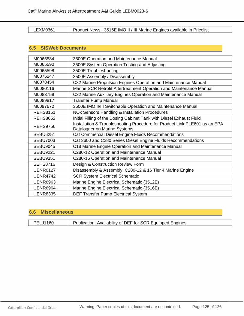
Warning: Paper copies of this document are uncontrolled. Page 125 of 126
Cat® Marine Air-Assist Aftertreatment A&I Guide LEBM0023-6
Caterpillar: Confidential Green
LEXM0361 Product News: 3516E IMO II / III Marine Engines available in Pricelist
6.5 SISWeb Documents
M0065584 3500E Operation and Maintenance Manual
M0065590 3500E System Operation Testing and Adjusting
M0065598 3500E Troubleshooting
M0075247 3500E Assembly / Disassembly
M0078454 C32 Marine Propulsion Engines Operation and Maintenance Manual
M0080116 Marine SCR Retrofit Aftertreatment Operation and Maintenance Manual
M0083759 C32 Marine Auxiliary Engines Operation and Maintenance Manual
M0089817 Transfer Pump Manual
M0097672 3500E IMO II/III Switchable Operation and Maintenance Manual
REHS8151 NOx Sensors Handling & Installation Procedures
REHS8652 Initial Filling of the Dosing Cabinet Tank with Diesel Exhaust Fluid
REHS9756 Installation & Troubleshooting Procedure for Product Link PLE601 as an EPA Datalogger on Marine Systems
SEBU6251 Cat Commercial Diesel Engine Fluids Recommendations
SEBU7003 Cat 3600 and C280 Series Diesel Engine Fluids Recommendations
SEBU9045 C18 Marine Engine Operation and Maintenance Manual
SEBU9221 C280-12 Operation and Maintenance Manual
SEBU9351 C280-16 Operation and Maintenance Manual
SEHS8716 Design & Construction Review Form
UENR0127 Disassembly & Assembly, C280-12 & 16 Tier 4 Marine Engine
UENR4742 SCR System Electrical Schematic
UENR6963 Marine Engine Electrical Schematic (3512E)
UENR6964 Marine Engine Electrical Schematic (3516E)
UENR8335 DEF Transfer Pump Electrical System
6.6 Miscellaneous
PELJ1160 Publication: Availability of DEF for SCR Equipped Engines

Warning: Paper copies of this document are uncontrolled. Page 126 of 126
Cat® Marine Air-Assist Aftertreatment A&I Guide LEBM0023-6
Caterpillar: Confidential Green
©2019 Caterpillar. All Rights Reserved. CAT, CATERPILLAR, LET’S DO THE WORK, their respective logos, "Caterpillar Yellow", the "Power Edge" and Cat “Modern Hex” trade dress as well as corporate and product identity used herein, are trademarks of Caterpillar and may not be used without permission.
LEBM0023-06
Related Documents