22102-CSA11357/1 Uen Rev A Marconi OMS 800 Optical MultiService Access Technical Product Description

Welcome message from author
This document is posted to help you gain knowledge. Please leave a comment to let me know what you think about it! Share it to your friends and learn new things together.
Transcript

22102-CSA11357/1 Uen Rev A
Marconi OMS 800 Optical MultiService Access
Technical Product Description

Marconi OMS 800 Optical MultiService Access
© Ericsson AB 2006 All rights reserved. The information in this document is the property of Ericsson. Except as specifically authorized in writing by Ericsson, the receiver of this document shall keep the information contained herein confidential and shall protect the same in whole or in part from disclosure and dissemination to third parties. Disclosure and disseminations to the receiver's employees shall only be made on a strict need to know basis. The information in this document is subject to change without notice and Ericsson assumes no responsibility for factual inaccuracies or typographical errors.
22102-CSA11357/1 Uen Rev A 12.02.2007 © Ericsson AB 2006 Commercial in confidence
2 (41)

Marconi OMS 800 Optical MultiService Access
Contents 1 Introduction............................................................................................ 8 1.1 Overview.................................................................................................. 8
2 Main Features and Benefits of the OMS 800 family.......................... 10
3 Product Overview ................................................................................ 14 3.1 OMS 846 ............................................................................................... 14 3.2 OMS 860 ............................................................................................... 15 3.3 OMS 870 ............................................................................................... 17
4 Features................................................................................................ 20 4.1 SDH Features........................................................................................ 20 4.1.1 Multiplexing Structure ............................................................................ 20 4.1.2 Mapping of Ethernet frames into VC-n .................................................. 20 4.1.3 STM-N Physical Layer........................................................................... 21 4.1.4 STM-N Regenerator and Multiplex Section layer .................................. 22 4.1.5 Concatenation schemes ........................................................................ 23 4.1.6 Protection .............................................................................................. 23 4.1.7 Performance monitoring ........................................................................ 24 4.1.8 Synchronisation ..................................................................................... 24 4.2 Ethernet over SDH Mapping.................................................................. 25 4.2.1 GFP ....................................................................................................... 25 4.2.2 VCAT and LCAS.................................................................................... 25 4.3 OMS 800 Ethernet features................................................................... 25 4.3.1 Ethernet Services .................................................................................. 26 4.3.2 Ethernet Functionality............................................................................ 28 4.3.3 Rate Limiting.......................................................................................... 32 4.3.4 Transport of user Traffic ........................................................................ 33 4.3.5 Performance Monitoring ........................................................................ 34 4.3.6 Ethernet Physical Layer......................................................................... 35 4.4 PDH Features........................................................................................ 36
5 DCN Features....................................................................................... 37
6 Technical Specifications..................................................................... 40 6.1 Mechanical design and requirements .................................................... 40 6.2 Safety .................................................................................................... 40 6.3 Environment .......................................................................................... 40 6.3.1 Electromagnetic compatibility (EMC)..................................................... 40 6.3.2 Climatic and Mechanical Environment................................................... 41
22102-CSA11357/1 Uen Rev A 12.02.2007 © Ericsson AB 2006 Commercial in confidence
3 (41)

Marconi OMS 800 Optical MultiService Access
List of Abbreviations AC Alternating Current ADM Add and drop multiplexer AIS Alarm Indication Signal AU Administrative Unit BALUN BALanced to Unbalanced BBE Background Block Error BPDU Bridge Protocol Data Unit CBR Committed Burst Rate CE Customer Edge CIR Committed Information Rate CLI Command Line Interface CLNP ConnectionLess Network Protocol COS Class Of Service CPE Customer Premises Equipment CRC Cyclic Redundancy Check CT Craft Terminal CWDM Cource Wavelength Division Mmultiplexing DC Direct Current DCC Data Communication Channel DCCX Data Communication Channel Cross-connect DCN Data Communication Network DEG Degradation DSUB Subminiature D connector DWDM Dense Wavelength Division Mmultiplexing DXC Digital Cross–Connect EBR Excessive Burst Rate EIR Excessive Information Rate E-LAN Ethernet LAN service E-LINE Ethernet LINE service EM Element manager EMC Electromagnetic Compatibility EOS Ethernet Over SDH EPL Ethernet Private Line EPLAN Ethernet Privat LAN ES Errored Second ESR Errored Second Ratio ET Exchange Terminal ETS European Telecommunications Standard ETSI European Telecommunication Standardization Institute EVC Ethernet Virtual Connection EVPL Ethernet Virtual Private Line EVPLAN Ethernet Virtual Privat LAN FC/PC Fibre Connector/Polished Contact FCS Frame Check Sequence FE Fast Ethernet GARP Generic Attribute Registration Protocol GE Gigabit Ethernet GFP Generic Framing Procedure
22102-CSA11357/1 Uen Rev A 12.02.2007 © Ericsson AB 2006 Commercial in confidence
4 (41)

Marconi OMS 800 Optical MultiService Access
GMRP GARP Multicast Registration Protocol GSM Global system for Mobile Communication GUI Graphical User Interface GVRP GARP VLAN Registration Protocol HDLC High-level Data Link Control IEC International Electrotechnical Commission IEEE Institute of Electrical and Electronics Engineers IETF Internet Engineering Task Force IGMP Internet Group Management Protocol IP Internet Protocol IPPM¨ Intermediate Path Performance Monitoring IPX Internetwork Packet eXchange ISDN Integrated Services Digital Network ISO International organisation for standardisation ITU International Telecommunication Union ITU-T International Telecommunication Union, Telecommunications
Sector L1 Layer 1 L1CC Layer 1 Communication Channel L2 Layer 2 LACP Link Aggregation Control Protocol LACPDU LACP Data Units LAG Link Aggregation Group LAN Local Area Network LAPS Link Access Procedure – SDH LC Lucent Connector LCAS Link Capacity Adjustment Scheme (for Virtual Concatenated
signals) LCT Local Craft Terminal LED Light Emitting Diode LFA Loss of Frame Alignment LFH Low Force Helix LLC Logical Link Control LOF Loss of Frame LOP Loss of Pointer LOS Loss of Signal LTU Line Termination Unit MAC Media Access Control MCN Management Communication Network MDI Medium Dependent Interface MEF Metro Ethernet Forum MEN Metro Ethernet Network MMF Multi Mode Fibre MPLS Multi protocol Label Switching MS Multiplex Section MSA Multi Source Agreement MS-AIS Multiplex Section – Alarm Indication Signal MSH Product name for Marconi SDH multiplexer MSOH Multiplex Section OverHead MSP Multiplex Section Protection MSPP Multi Service Provision Platform
22102-CSA11357/1 Uen Rev A 12.02.2007 © Ericsson AB 2006 Commercial in confidence
5 (41)

Marconi OMS 800 Optical MultiService Access
MSTP Multiple Spanning Tree Protocol MTBF Mean Time Between failures MUX Multiplexer NE Network Element NM Network manager NMS Network Management System NNI Network to Network Interface NSAP Network Service Access Point OAM Operation Administration Maintenance OSI Open System Interconnection OSPF Open Shortest Path First PC Personal Computer PDH Plesiochronous Digital Hierarchy PM Performance Monitoring POH Path Overhead POP Point Of Presence PPP Point to Point Protocol PRA Primary Rate Access PSU Power Supply Unit QoS Quality of Service RMON Remote MONitoring RSOH Regenerator Section OverHead RSTP Rapid Spanning Tree Protocol RU Rack Units SDH Synchronous Digital Hierarchy SDRAM Synchronous Dynamic Random Access Memory SEC SDH Equipment Clock SES Severely Errored Second SESR Severely Errored Second Ratio SETG Synchronous Equipment Timing Generator SETS Station Equipment Timing Synchronisation SFP Small Form Pluggable SLA Service Level Agreement SMF Single Mode Fibre SNC/I Sub Network Connection/Inherent SNC/N Sub Network Connection/Non Inherent SNCP Sub-Network Connection Protection SNMP Simple Network Management Protocol SoA Service on Access, Network Management System SOH Section OverHead SSU Synchronisation Supply Unit STM Synchronous Transport Module STM-N Synchronous Transport Module - N STP Spanning Tree Protocol TDM Time Division Multiplexing TE Terminal Equipment TLS Transparent LAN Service TM Terminal Multiplexer TMN Telecommunication Management Network TOS Type Of Service TPID Tag Protocol IDentifier
22102-CSA11357/1 Uen Rev A 12.02.2007 © Ericsson AB 2006 Commercial in confidence
6 (41)

Marconi OMS 800 Optical MultiService Access
TU Tributary Unit TUG Tributary Unit Group UAS Unavailable Seconds UNI User Network Interface VC Virtual Container VCG Virtual Container Group VID VLAN IDentifier VLAN Virtual Local Area Network WAN Wide Area Network
Foreword The product information contained herein is independent of product release. The technical information provided in this document is offered, in good faith, as an indication of Ericsson's intention to evolve its Optical Networks portfolio to meet the demands of the marketplace. Unless commercially agreed, the information contained herein should not to be taken as implying any commitment or obligation on the part of Ericsson. For details concerning availability and supported features please refer to the Product Area Optical Networks Commercial Roadmap.
22102-CSA11357/1 Uen Rev A 12.02.2007 © Ericsson AB 2006 Commercial in confidence
7 (41)

Marconi OMS 800 Optical MultiService Access
1 Introduction
1.1 Overview
The Ericsson OMS 800 product family has been designed as part of Ericsson’s OPTO product offering for converged metro and access transport, for mobile and fixed networks with necessary commonality such as service features and network management. Any mix of TDM and broadband data services can be delivered, and the different solutions are designed to give the operator the necessary tools for scalability and flexibility in the design of the different parts of the Access Network covering Business Customer, Mobile Radio Access, Broadband Access/DSLAM backhaul and Enterprise solutions.
OMS 800 is well positioned for network operator where the majority of the traffic today is based on TDM and where convergence towards packet transport is the major future growth. OMS 800 offers a comprehensive set of features in order to leverage the network operator’s investments taken into account everything from legacy SDH solutions to NG-SDH solutions when offering Ethernet services. All these features are implemented using the latest technology that makes it easy to introduce these new advanced Ethernet Services where service differentiation can be implemented including control mechanisms for customer SLA’s.
Three products form the OMS 800 product family, and the essential difference between the products are aggregate capacity, number of interfaces supported and cost as an important requirement in each part of the network.
• OMS 846 is an ADM-1 (2xSTM-1) delivered as two fixed variants, either with 4xFE (Layer 1) or 1xGE (Layer 1). In addition both variants have fixed 2xSTM-1 SFP tributary interfaces and 16xE1 interfaces.
• OMS 860 is an ADM-4 (2xSTM-1/4) delivered in two variants, either with or without 16 x E1 interfaces. Both variants have 2 slots for optional modules.
• OMS 870 is an ADM-16 platform where Aggregate and Tributary interfaces are decided by the plug-in modules selected for the 4 slots in the Base module. OMS 870 can also connect to either an SDH based or Packet based network.
The feature set of OMS 846, 860 and 870 are based on the same technology (HW and SW), and all managed on the same platform including Craft Terminal SW, Element and Subnetwork manager, Service On Optical.
The table below shows the capacities of the different variants.
22102-CSA11357/1 Uen Rev A 12.02.2007 © Ericsson AB 2006 Commercial in confidence
8 (41)

Marconi OMS 800 Optical MultiService Access
SDH E1 E3/T3 GE#Map FE/GE
L2 switching
MEF(CIR, CBS, EIR, EBS, RL)
Power Consump.
(W)OMS 846 4xSTM-1 16 - 4 2) 1 4/1 No Yes <20
OMS 8604xSTM-1 + 2xSTM-1/4 80 6 8 1 8/1 Yes Yes <50
OMS 870STM-1/4
/16
1) 24xSTM-1, 12xSTM-4, 3xSTM-16 189 18 24 3) 6 48/6 Yes Yes <120
Remark: 1
2 OMS 846 delivered as fixed configurations, either GE or FE.3 Some power limitations may be applicable
Aggr. Cap.
This example, one slot used for Aggregate and 3 slots for Tributaries.Other configurations are possible.
FESTM-1
STM-1/4
Table 1. OMS 800 Product comparison.
All three OMS 800 products are housed in small compact 19”/ETSI wide and1u high boxes.
All optical interfaces support pluggable SFP (Small Form-factor Pluggable) modules, and together with pluggable optional HW modules, except OMS 846 which is fixed, giving greater flexibility and cost savings when building and maintaining an optical network.
OMS 800 products are designed in accordance with telecommunication industry standards and provide the necessary carrier-class performance features required in this part of the network. All products are supported by a state-of-the-art management solution (Service On Optical) ensuring cost-efficient network operation and rapid introduction of new services across the complete Ericsson Optical product portfolio.
22102-CSA11357/1 Uen Rev A 12.02.2007 © Ericsson AB 2006 Commercial in confidence
9 (41)
Marconi OMS 800 Optical MultiService Access
2 Main Features and Benefits of the OMS 800 family
22102-CSA11357/1 Uen Rev A 12.02.2007 © Ericsson AB 2006 Commercial in confidence
10 (41)
OMS 800 is a well recognised and proven technology where operators are using the platform for grooming and transport of TDM and packet traffic. OMS 800 has been widely deployed with a high percentage of Ethernet ports shipped. Ethernet has been one of the main drivers for the development, and latest standards are implemented in order to offer flexibility in the process of establishing new packet based services. The main enhancements on latest releases focus on new Ethernet features, and lately more advanced policing functionality including Rate limitation, CIR, CBS, EIR and EBS together with high flexibility in how classification and VLAN handling is implemented in the OMS 800 platform.
SDH developments ha been important for the platform and all latest standard technology is supported such as GFP, VCAT and LCAS for easy transport of Ethernet.
DCN is also an important part in order to have flexibility when designing networks, and key features are interoperability with other vendors SDH equipment together with easy transport in any topology that the operators when rolling out a new telecom infrastructure.
The network elements are supported by a power full GUI and necessary wizards in order to do complicated tasks when installing the network elements or doing repetitive configurations where installation time is important.
One main difference in the way Ericsson has designed these network elements is shown by, for example, the OMS 870 with its dual bus structure where all TDM interfaces are connected to the TDM switching matrix and the packet based interfaces are connected to an Ethernet switching matrix (Layer 2 switching if applicable). This gives a great advantage when a mix of traffic is necessary in the Access part of the network to ensure resources such as Ethernet over SDH mappers are only used when traffic should be mapped into a WAN TDM circuit (i.e. one or number of VC-circuits). Local Ethernet traffic will be switched using the Ethernet switching matrix and do not need the SDH switching capacities in the core of the network.

Marconi OMS 800 Optical MultiService Access
Ethernet over SDH has been implemented by using GFP, VCAT and LCAS. Before Ethernet packets are mapped into SDH/TDM circuits they are measured according to a policing functionality based on the actual SLA (Service Level Agreement) that is applicable for the traffic. This policing functionality is applicable for both Ethernet Layer 1 and Layer 2 services or EPL, EVPL and ELAN services belonging to a given UNI (User Network Interface) and can be set based on a per port, CE-VLAN or a combination of CE-VLAN and priority. Policing functionality includes Rate Limitations in steps of 500 kbps for FE ports and 1 Mbps for GE ports, tag-in-tag (QinQ) for transparent customer traffic including customer control packets, priority and class of service treatment. Rate Limitation has been implemented using a dual bucket principle where packets are measured according to Committed Information Rate (CIR), Committed Burst Size (CBS), Excess Information Rate (EIR) and Excess Burst Size (EBS). Packets will be accordingly “coloured” green, yellow or red (dropped). All SLA parameters are subject for performance measurement and available for reporting through the management system.
The switching matrixes (SDH/TDM and Ethernet) are non-blocking. Thus, there is no need for resource planning of available capacity in the network element itself other than the available WAN capacity (i.e. the uplink capacity of each network element). The Ethernet can be switched at wire speed for all ports, again provided that the WAN capacity is sufficient.
TDM traffic is directly connected to the TDM/SDH matrix and for E1 (2Mpbs) interfaces different configurations are available such as support for ISDN PRA, G.703 and G.704 support. E3/T3 (34/45Mpbs) modules/interfaces are also available.
Main characteristics and features of OMS 800 platform are as follows;
• Easy implementation of new revenue generating services
• Multi-service device with a mix of E1, E3/T3, STM-1/4/16, 10/100/1000 Ethernet interfaces
• Aggregate speed up to 2,5 Gbit/s (SDH) or 1 GE (Ethernet)
• Optical interfaces based on SFP
• Support of CWDM (8 wave lengths)
• Support of Ring, star and linear topologies.
• Ethernet traffic is encapsulated and transported over SDH using Generic Framing Procedure (GFP) in accordance with ITU-T G.7041
• Virtual Concatenation (VCAT) in accordance with ITU-T G.707
• Link Capacity Adjustment Scheme (LCAS) in accordance with ITU-TG.7042
22102-CSA11357/1 Uen Rev A 12.02.2007 © Ericsson AB 2006 Commercial in confidence
11 (41)

Marconi OMS 800 Optical MultiService Access
• Ethernet Line-service (point-to-point) and Ethernet LAN-service (multipoint-to-multipoint) support.
• Ethernet Policing including rate limitation, CIR, CBS, EIR, EBS
• MSP 1+1 Protection
• SNCP protection in ring, dual parenting or meshed topology
• STP/RSTP Protection
• Link Aggregation
Ethernet Layer 1 mode supports the following features;
• Rate limitations per port/VLAN
• CIR, CBS, EIR, EBS
• Provider Tagging (802.1ad, QinQ)
• IEEE 802.1 p Priorities
Ethernet Layer 2 mode supports the following features:
• MAC multicast
• IGMP snooping
• IEEE 802.1q VLAN tagging
• GARP VLAN registration Protocol (GVRP)
• Provider Bridging
• Tunnelling of user traffic (QinQ)
• Tunnelling of user protocols
• Enhanced OAM
• Rate limitations per port/VLAN
• Spanning Tree Protocol (STP) in accordance with IEEE 802.1w
• Rapid Spanning Tree Protocol (RSTP) in accordance with IEEE 802.1w
• Rate limitations per port/VLAN
22102-CSA11357/1 Uen Rev A 12.02.2007 © Ericsson AB 2006 Commercial in confidence
12 (41)

Marconi OMS 800 Optical MultiService Access
• CIR, CBS, EIR, EBS
• IEEE 802.1 p Priorities
22102-CSA11357/1 Uen Rev A 12.02.2007 © Ericsson AB 2006 Commercial in confidence
13 (41)

Marconi OMS 800 Optical MultiService Access
3 Product Overview
3.1 OMS 846 OMS 846 has been optimised to provide a very cost effective solution. Two different variants are available, one with 4xFE interfaces and one with 1xGE interface. Both variants have 2 tributaries, SFP based, for drop of STM-1 and 16xE1 (75 Ohm or 120 Ohm). The figures below show the layout of the front panel.
Figure: 1. OMS 846 with 4xFE and 16xE1/RJ45 (120 Ohm)
Figure 2. OMS 846 with 1xGE and 16xE1 (75 Ohm)
OMS 846 has an uplink capacity of up to 4xSTM-1, SFP based optical and electrical interfaces, and supports terminal multiplexing, add drop multiplexing and cross connect functionality.
OMS 846 is delivered in standard version with -48 VDC power feeding. AC power supply is provided using an AC/DC adapter that can be fixed to the left hand 19” or ETSI rack mounting bracket.
22102-CSA11357/1 Uen Rev A 12.02.2007 © Ericsson AB 2006 Commercial in confidence
14 (41)

Marconi OMS 800 Optical MultiService Access
ACD
CAd
apte
r
STM-1-SFP
TDM Matrix
STM-1-SFP
24x24HO/LO
Slot #4(variant#2)
GE FE+MAP
Pow
er- 4
8 VD
C
Slot #4(variant#1)
Slot #3 Slot #2Trib
1 1 4 1 16 1 2 1 2
E1
SystemController
Slot #1Agg
ACD
CA
dapt
er
STM-1-SFP
TDM Matrix
STM-1-SFP
24x24HO/LO
Slot #4(variant#2)
GE FE+MAP
Pow
er- 4
8 VD
C
Slot #4(variant#1)
Slot #3 Slot #2Trib
1 1 41 4 1 16 1 21 21 2 1 21 21 2
E1
SystemControllerSystemController
Slot #1Agg
Figure 3: OMS 846 Architecture block diagram.
Applications:
• as a CPE to connect businesses, business parks, mobile network base stations, DSLAMs, WLAN/WiMAX hot-spots or other entities
• Linear topologies and rings at STM-1 level with optional STM-1 optical/electrical drop
System capacities:
• TDM matrix: 24x24 STM-1 non-blocking at VC-4, VC-3 and VC-12.
• Maximum power consumption: 25 Watts
3.2 OMS 860 OMS 860 has an uplink capacity of 2xSTM-1/4 selected by SFP modules, one fixed tributary with 16xE1 (120 Ohm) and 2 optional slots for hot insertion of optional tributaries. The figure below shows the layout of the front panel with the two optional slots to the Left.
Figure 4: OMS 860 front view with 16xE1 and two optional modules, 4xFE and 3xE3/T3.
22102-CSA11357/1 Uen Rev A 12.02.2007 © Ericsson AB 2006 Commercial in confidence
15 (41)

Marconi OMS 800 Optical MultiService Access
OMS 860 can run wire speed 1xGE in combination with E1/E3/T3 or FE depending on the type of optional module selected. The figure below shows the high level layout/architecture of OMS 860:
TDM Matrix Ethernet Cross-Bar
SDH
STM-1/4-SFP
24x24HO/LO
PDH
Slot #2(optional)
Slot #1(optional)
E1
• 4xFEL1/2+4 Map• 3xE3/T3• 32xE1
• 4xFEL1+4 Map• 3xE3/T3• 32xE1• 1xGE+1Map
Pow
er- 4
8 V
DC
AC
DC
Adap
terBase Unit
Slot#3
(optional.)
Slot#4
1 16 1 2
TDM Matrix Ethernet Cross-Bar
SDH
STM-1/4-SFP
24x24HO/LO
PDH
Slot #2(optional)
Slot #1(optional)
E1
• 4xFEL1/2+4 Map• 3xE3/T3• 32xE1
• 4xFEL1+4 Map• 3xE3/T3• 32xE1• 1xGE+1Map
Pow
e r- 4
8 V
DC
AC
DC
Adap
terBase Unit
Slot#3
(optional.)
Slot#4
1 16 1 2
Figure 4 : OMS 860 Architecture block diagram.
OMS 860 has an internal bus structure based on STM-4, and one tributary position with 2xSTM-4 (GE position) and one tributary position supporting Ethernet Layer 2. OMS 860 supports terminal multiplex, add drop multiplex, cross connect, layer 2 Ethernet switching, EoS (Ethernet over SDH) functionality.
Applications:
• As CPE to connect businesses, business parks, mobile network base station, DSLAM, WLAN/WiMAX hot-spots or other entities
• Linear topologies and rings at STM-1 and STM-4
• Optical or Electrical STM-1 drop (rel.1.3)
Following modules are available or planned for future releases:
• 32xE1-LFH
• 3xE3/T3
• 4xFE-L1+4xMAP
• 4xFE-L2+4xMAP
• 1xGE + 1x MAP
22102-CSA11357/1 Uen Rev A 12.02.2007 © Ericsson AB 2006 Commercial in confidence
16 (41)

Marconi OMS 800 Optical MultiService Access
• 4xSTM-1-SFP
System capacities:
• TDM matrix: 24x24 STM-1 non-blocking at VC-4, VC-3 and VC-12.
• Ethernet cross-bar: 5 Gbps
• Maximum power consumption: 50 Watts
3.3 OMS 870 OMS 870 is unique when comparing size and traffic capacity available in only 19” and a 1u high box.
The figure below shows the layout of the front panel
Picture 5: OMS 870 front view.
OMS 870 has two power slots for single or protected power (-48 VDC). For mains power an external AC/DC power adapter is provided.
OMS 870 has an internal bus structure based on STM-16 for TDM traffic and 2xGbps for interconnection of Ethernet modules. The figure below shows the high level layout/architecture of OMS 870:
22102-CSA11357/1 Uen Rev A 12.02.2007 © Ericsson AB 2006 Commercial in confidence
17 (41)

Marconi OMS 800 Optical MultiService Access
TDM Matrix Ethernet Cross-Bar
Service Mod. #4
64X64HO/LO
Service Mod. #3
Service Mod. #2
Service Mod. #1•8xFE+16Map•8xFE-SFP•2xGE+2Map•8/63xE1•6xE3/T3•8xSTM1-SFP•4xSTM4-SFP•1xSTM16-SFP
10 Gb
2x P
owe r
-48
VD
C
ANY COMBINATIONS
AC
DC
Adap
terBase Unit TDM Matrix Ethernet Cross-Bar
Service Mod. #4
64X64HO/LO
Service Mod. #3
Service Mod. #2
Service Mod. #1•8xFE+16Map•8xFE-SFP•2xGE+2Map•8/63xE1•6xE3/T3•8xSTM1-SFP•4xSTM4-SFP•1xSTM16-SFP
10 Gb
2x P
o we r
-48
VDC
ANY COMBINATIONS
AC
DC
Adap
terBase Unit
Figure 6: OMS 870 Architecture block diagram OMS 870 supports terminal multiplexing, add-drop multiplex, cross connect, layer 2 Ethernet switching, EoSDH functionality and combinations of those. Applications:
• as an Access grooming device in an operator’s point of presence (POP), towards the edge of the network
• as a high-end single customer CPE, or CPE to connect businesses, business parks, mobile network stations, DSLAMs, WLAN/WiMAX hot-spots or other entities.
• Supports Star, linear, ring, mesh or combined topologies, at STM-1, STM-4, STM-16, Ethernet (E), Fast Ethernet (FE) or Gigabit Ethernet (GE) levels.
Service modules (Trib/Agg) - 4 generic slots for plug-in of hot-swappable modules. Any module can be used in any position. Plug-in modules available:
• 8xFE LAN ports + 16xMAP. Module configurable as Layer 1 or Layer2, and has 16 Ethernet over SDH mappers that can be used as a resource for this specific module or a combination with other Ethernet modules in the system.
• 8xFE-SFP, LAN ports with SFP-based optical plug-in. Module configurable as Layer 1 or Layer 2. If mapping over SDH is required then this can be done by using the module resources above.
• 2xGE LAN ports, SFP-based + 2xMAP. Electrical and optical GE interfaces are supported with Layer 2 switching.
• 8xSTM-1-SFP interfaces
22102-CSA11357/1 Uen Rev A 12.02.2007 © Ericsson AB 2006 Commercial in confidence
18 (41)

Marconi OMS 800 Optical MultiService Access
• 4xSTM-4-SFP interfaces
• 1xSTM-16-SFP interface
• 63xE1-LFH interfaces
• 8xE1- RJ45 interfaces
• 6xE3/T3 interfaces, individually configurable to E3 or T3
• 21xE1 + 3xE3/T3 interfaces
• System capacities:
• TDM matrix: 64x64 STM-1equivalent non-blocking at VC-4, VC-3 and VC-12 level.
• Ethernet cross-bar: 10 Gbps
• Maximum power consumption: 120 Watts
22102-CSA11357/1 Uen Rev A 12.02.2007 © Ericsson AB 2006 Commercial in confidence
19 (41)

Marconi OMS 800 Optical MultiService Access
4 Features
4.1 SDH Features
4.1.1 Multiplexing Structure The OMS 800 products comply with the basic ITU-T and ETSI based SDH multiplexing principles. OMS 846 supports the multiplexing structure outlined in Figure 7. This is applicable for STM-1, OMS 860 multiplexing including STM-4 and OMS 870 including STM-16 level and support for mapping of asynchronous E1 (2 048 Kbps), E3 (34 368 Kbps) and T3 (44 736 Kbps) interfaces into VC-n.
Figure 7 Supported multiplexing structures
4.1.2 Mapping of Ethernet frames into VC-n OMS 800 supports GFP – F (Generic Framing Procedure – Framed Map), according go G.7041, to encapsulate variable length payload of various client packet/Ethernet traffic into VC-n and for subsequent transport over SDH networks as defined in the ITU-T G.707. OMS 800 also supports Ericsson AXXESSIT’s proprietary mapping scheme for mapping of Ethernet traffic into a number of VC-12 containers.
22102-CSA11357/1 Uen Rev A 12.02.2007 © Ericsson AB 2006 Commercial in confidence
20 (41)

Marconi OMS 800 Optical MultiService Access
4.1.3 STM-N Physical Layer All SDH optical interfaces are based on SFP’s, and following modules are qualified for OMS 800:
10-24-28-3/21280-1355622 080L-4.1
10-24-28-3/21500-15802 448 380L-16.2
10-24-27-3/21280-13552 448 380L-16.1
0-12-18-5/01261-13602 448 380S-16.1
10-24-28-3/21480-1580622 080L-4.2
0-12-28-15/-81293-1334/ 1274-1356
622 080S-4.1
10-28-34-5/01480-1580155 520L-1.2
10-28-34-5/01263-1360155 520L-1.1
0-12-28-15/-81261-1360155 520S-1.1
OpticalBudget dB
Sensitivity(min) dBm
Launched Power (min/max) dBm
Wavelength nm
Line ratekbps
Interface
Table 2. SDH STM-n SFP optical modules supported by OMS 800
10-30-320/51471, 1491, 1511, 1531, 1551, 1571, 1591, 1611
2 448 380
“L-16.2V”CWDM
10-31-320/51471, 1491, 1511, 1531, 1551, 1571, 1591, 1611
622 080“L-4.2V”CWDM
10-33-340/51471, 1491, 1511, 1531, 1551, 1571, 1591, 1611
155 520“L-1.2V”CWDM
10-26-280/51471, 1491, 1511, 1531, 1551, 1571, 1591, 1611
2 448 380
“L-16.2C”CWDM
10-27-280/51471, 1491, 1511, 1531, 1551, 1571, 1591, 1611
622 080“L-4.2C”CWDM
10-27-280/51471, 1491, 1511, 1531, 1551, 1571, 1591, 1611
155 520“L-.2C”CWDM
OpticalBudget
dB
Sensitivity(min) dBm
Launched Power
(min/max) dBm
Wavelength nm
(+/- 6.5 nm)
Line ratekbps
Interface
Table 3. SDH CWDM STM-n SFP optical modules supported by OMS 800 All optical interfaces are using LC-connector. The Following electrical STM-1 SFP is qualified for OMS 800:
0-12.7 dB at 78 MHz
Cable attenuation
NA
Cable length
1.0/2.3155 520STM-1e
Connector typeLine rate kbps
Interface
0-12.7 dB at 78 MHz
Cable attenuation
NA
Cable length
1.0/2.3155 520STM-1e
Connector typeLine rate kbps
Interface
Table 4. SDH STM-1 electrical SFP.
22102-CSA11357/1 Uen Rev A 12.02.2007 © Ericsson AB 2006 Commercial in confidence
21 (41)

Marconi OMS 800 Optical MultiService Access
4.1.4 STM-N Regenerator and Multiplex Section layer
22102-CSA11357/1 Uen Rev A 12.02.2007 © Ericsson AB 2006 Commercial in confidence
22 (41)
OMS 800 family implements the STM-N (N=1,4 and16) Regenerator and Multiplex Section layer functions in accordance to ITU-T G.783. OMS 846 supports STM-1, OMS 860 supports STM-1/4 and OMS 870 supports STM-1/4/16. VC-n/m Path layer OMS 800 family supports the following payloads:
• VC-4
• VC-4-4c (OMS 870 only)
• VC-4-Xv (OMS 860 and OMS 870)
• VC-3
• VC-3-Xv
• VC-12
• VC-12-Xv VC-4-Xc/VC-4/VC-3 POH implementation The OMS 800 supports VC-4-Xc/VC-4/VC-3 POH bytes according to ITU-T G.707.
VC-12 POH implementation The OMS800 supports VC-12 POH bytes as described in ITU-T G.707
Cross-connect support OMS 800 has a two stage cross connect, consisting of a higher order and a lower order part. The higher order and low order parts are non-blocking and equal to 64x64 STM-1 equivalents for OMS 870, 24x24 STM-1 equivalents for OMS 860 and 846 and offer connections for the following objects:
• VC-12
• VC-3
• VC-4
• VC-4-4c (OMS 870 only)
The OMS 800 cross connect matrix supports different cross connect basic types, which are used to build more complex cross connects.
• The basic cross connect types are:
o Uni-directional, un-protected point-to-point o Bi-directional, un-protected point-to-point o Uni-directional, protected point-to-point of type “add”

Marconi OMS 800 Optical MultiService Access
o Uni-directional, protected point-to-point of type “drop” o Bi-directional, protected point-to-point
4.1.5 Concatenation schemes OMS 800 family supports Virtual Concatenation (VCAT) and following VC-n-Xv are supported:
• VC-12-Xv
• VC-3-Xv
• VC-4-Xv Virtual concatenation is supported in conjunction with EOS mapping and is module dependent.
In addition, OMS 870 supports standard contiguous concatenation at VC-4-4c level.
4.1.6 Protection OMS 800 offers a vide range of different protection schemes such as;
• 1+1 MSP
• SNCP
• LCAS
4.1.6.1 MSP 1+1 Linear Protection OMS 800 offers 1+1 linear Multiplex Section Protection (MSP) on all STM-N interfaces.
The following rules apply for the 1+1 MSP protection:
• Protection can only be enabled between two ports of the same STM-N type In addition, applicable for OMS 870;
• Protection can be enabled between two ports located on different modules. Note that the ports on module 1 protect the ports on module 2 and the ports on module 3 protect the ports on module 4.
4.1.6.2 SNC Protection OMS 800 family supports two types of SNC protection, SNC/I (Sub Network Connection protection with Inherent monitoring) and SNC/N (Sub Network Connection protection with non-intrusive monitoring). SNC Protection (SNCP) is supported for the following layers:
• VC-12
• VC-3
22102-CSA11357/1 Uen Rev A 12.02.2007 © Ericsson AB 2006 Commercial in confidence
23 (41)
Marconi OMS 800 Optical MultiService Access
• VC-4
• VC-4-4c (OMS 870 only)
4.1.7 Performance monitoring OMS 800 family offers a wide range of performance monitoring mechanisms at different levels in the system. The following performance monitoring functions are available;
• Regenerator and multiplex section (ES, SES, BBE and UAS)
• Path (ES, SES, BBE and UAS)
• Intermediate Path (IPPM)
• SNCP (Protection switching count and Duration)
• MSP (Protection switching count and Duration)
• Pointer Justification (+/- pointer justifications of AU-4, AU-4-4c)
4.1.8 Synchronisation OMS 800 family contains a T0 synchronization selection process, operating in QL-enabled mode. The process is responsible for selecting the best signal source to be used as reference input for the SETS, generating the T0 clock. The selection is carried out from a number of nominated sources configured by the network operator as follows;
• SDH STM-N signals (N=1, 4, 16)
• 2 Mbps signal (E1), G.704 or ISDN PRA
• 2 MHz external synchronisation signal
• Free running mode (G.813 compliant) OMS 800 family supports typically up to 20 Nodes in serial without new reference clocking (acc.to ITU-T 803). The total number of nodes in serial is typically 60 nodes when reference clocks are used.
OMS 800 family also contains a selection process, responsible for selecting the reference source for the T4 ports (which is the synchronisation output port). This selection is done among ingress T1 signal sources contained in a selection list. The T4 output ports can also be locked to the internal T0 clock.
22102-CSA11357/1 Uen Rev A 12.02.2007 © Ericsson AB 2006 Commercial in confidence
24 (41)

Marconi OMS 800 Optical MultiService Access
4.2 Ethernet over SDH Mapping
22102-CSA11357/1 Uen Rev A 12.02.2007 © Ericsson AB 2006 Commercial in confidence
25 (41)
4.2.1 GFP OMS 800 family supports two different mapping schemes, one based on GFP mapping and one based on Ericsson AXXESSIT proprietary mapping. This section will only focus on standardised mapping (GFP). GFP-F mapping is according to ITU-T G.7041. GFP-F mapping scheme includes mapping protocol, concatenation scheme and control protocols. GFP support frame sizes from 64 bytes up to 9 Kbytes, and several alarm, event and performance parameters are monitored.
4.2.2 VCAT and LCAS OMS 800 family supports Virtual Concatenation according to ITU-T G.707 and the following mapping schemes are available:
• FE (Fast Ethernet) mapper interface; • VC-12-nV, where n=1..50 • VC-3-nV, where n=1..3 • VC-4-nV, where n=1
• GE (Gigabit Ethernet) mapper interface;
• VC-3-nV, where n=1..21
• VC-4-nV, where n=1..7 OMS 800 family supports the LCAS protocol in conjunction with VCAT as defined in ITU-T G.7042, and two different modes has been implemented; VCAT with or without LCAS enabled.
4.3 OMS 800 Ethernet features OMS 800 family has been implemented with different options related to whether the network operator wants to offer point to point Ethernet services (EPL), virtual point to point services (EVPL) where several customers can share a VC channel or a group of VC-nV and multipoint services or ELAN/EVLAN where the operator can offer services where they can share VC channels or group of VC-nV. Ethernet interfaces that support Layer 1 contain one or more Ethernet over SDH (EOS) mappers. The EOS mappers are used to map the Ethernet traffic over SDH, or VC-n/VC-nV channels. The modules that support Switching contain an Ethernet switch in addition to the Ethernet interfaces and the EOS mappers. The OMS 870 offers in addition a scalable distributed switching scheme. Each Ethernet module (FE and GE) has a Layer 2 switch and they are again connected through a crossbar on the aggregate module, and that makes OMS 870 behave like one switch consisting of multiple switching modules.

Marconi OMS 800 Optical MultiService Access
This makes it possible to switch traffic between different modules without using the EOS mapper capacities in the Node. Two types of EOS mappers are supported:
• Mapping of Fast Ethernet (FE) port into Virtual Containers (NxVC-12/3/4) • Mapping of Gigabit Ethernet (GE) port into Virtual Containers (NxVC-3/4)
4.3.1 Ethernet Services The technical definition of an Ethernet service is defined in terms of what is seen by each Customer Edge (CE). This includes the User Network Interface (UNI), which is the physical demarcation point between Service Provider and Subscriber (see figure below).
UNI
Metro Ethernet Network
User NetworkInterface
UNI
Customer Edge Customer Edge
EVC
UNI
Metro Ethernet Network
User NetworkInterface
UNI
Customer Edge Customer Edge
EVC
Figure 8 Ethernet Service Model Ethernet Services and attributes supported in OMS 800 family are based on Metro Ethernet Forum (MEF), MEF 9 and MEF 14. OMS 860 and OMS 870 are EPL, EVPL and ELAN certified. OMS 846 will be certified when released for commercial use. Ethernet services are using Ethernet Virtual Connection (EVC) for transport of traffic between 2 or more UNI’s, and two types of EVC’s are defined, i.e. point-to-point and multipoint to multipoint. In a point to point EVC, exactly two UNI’s are associated with one another. An ingress Service Frame to the EVC at one UNI does not result in an egress Service Frame at a UNI other than the UNI in the EVC. The figure below illustrates two point to point EVC’s.
22102-CSA11357/1 Uen Rev A 12.02.2007 © Ericsson AB 2006 Commercial in confidence
26 (41)

Marconi OMS 800 Optical MultiService Access
UNI2
Metro Ethernet Network
Customer Edge Customer Edge
EVC1
UNI3
UNI1
EVC2
Customer Edge
UNI2
Metro Ethernet Network
Customer Edge Customer Edge
EVC1
UNI3
UNI1
EVC2
Customer Edge
Figure 9. Point to point EVC. In a multipoint to multipoint EVC, two ore more UNI’s are associated with one another. An ingress Service Frame to the EVC at one of the UNI’s does not result in an egress Service Frame at a UNI that is not in the EVC. The rules under which a frame is delivered to a UNI in the EVC are specific to the particular service definition. Typically, a single broadcast or multicast ingress Service Frame (as determined from the destination MAC address) at a given UNI would be replicated in the Metro Ethernet Network and single copy would be delivered to each of the other UNI’s in the EVC. The figure below illustrates a multipoint to multipoint EVC.
UNI2
Metro Ethernet Network
Customer Edge
Customer Edge
UNI3
UNI1
Customer Edge
UNI2
Metro Ethernet Network
Customer Edge
Customer Edge
UNI3
UNI1
Customer Edge
Figure 10: Multipoint to multipoint EVC
The UNI List for an EVC is a list of UNI identifiers. The list has exactly one UNI Identifier for each UNI in the EVC. There are a number of different service frames; Unicast, multicast, broadcast and L2 control protocols service frames. Layer 2 protocols have to be processed and managed in the network based on destination MAC address. Layer 2 customer control packets may also be desirable to be carried across a Service Provider network, called Layer 2 control protocol tunneling.
22102-CSA11357/1 Uen Rev A 12.02.2007 © Ericsson AB 2006 Commercial in confidence
27 (41)

Marconi OMS 800 Optical MultiService Access
Service frames at ingress and egress of a UNI may use a 802.1Q tag or not. It is also possible to specify whether the VLAN part and/or the COS shall be preserved.
22102-CSA11357/1 Uen Rev A 12.02.2007 © Ericsson AB 2006 Commercial in confidence
28 (41)
For a given EVC at a given UNI, the Service Provider defines which Layer 2 protocols will be tunnelled via the EVC and which will be discarded.
4.3.2 Ethernet Functionality This section gives an overview of Ethernet functionality supported by the different Ethernet modules used in OMS 846, OMS 860 and OMS 870.
4.3.2.1 Physical Interfaces Auto-negotiation Fast Ethernet (FE) – RJ45 (Copper based) ports support 10 Mbps and 100 Mbps line rates. The FE optical ports only support 100 Mbps line rate and the Gigabit Ethernet (GE) supports only 1000 Mbps optical (SFP) or copper (RJ-45). Each LANx port supports both half and full duplex, and back pressure (half duplex) or flow control (full duplex). Operational mode can either be fixed by the operator’s setting from the management system or by auto-negotiation. Auto crossover OMS 800 supports auto crossover allowing connection to a Switch or Router by an ordinary Ethernet cable. Ethernet frame size OMS 800 family supports frame sizes up to 9K octets for Layer 1 traffic and up to 6144 octets for Layer 2 traffic. Default maximum frame size is 1536 octets. MAC address Each physical port has a MAC address allocated that can either be the same as the management port or a unique address for the specified port. LED indicators The Ethernet copper interfaces have two LED’s to indicate the link status and speed of the link and the optical has one LED to indicate link status. Forced LAN down Forced LAN down is a feature that deactivates a LANx port if the WAN channel is down (only applicable for Layer 1).
4.3.2.2 Ethernet Switching Ethernet modules supporting Layer 2 includes transparent switching (bridging) which means that it has the following features:
• Promiscuous listing on all its ports and store and forwarding between ports. • Self Learning (MAC addresses).

Marconi OMS 800 Optical MultiService Access
• Rapid Spanning Tree protocol per device (RSTP) Promiscuous listening means that the switch listens to all traffic sent on all its ports and frames that should be sent to other ports are identified and sent to appropriate ports. The bridge is able to learn MAC addresses and store them together with information about its port. When a frame arrives with a known MAC address, the bridge can forward the frame to that port only and avoiding broadcasting to all ports. MAC addresses are stored and maintained in a forwarding cache. To avoid the cache is fillling up with irrelevant MAC addresses, OMS 800 applies ageing to the entries in the cache. MAC address table (Forwarding cache) size is configurable up to a maximum of 32,000 entries. Static MAC addresses OMS 800 family supports static MAC address per port, configurable from the management system. Ageing algorithm does not apply for static MAC addresses.
4.3.2.3 VLAN VLAN makes it possible to create several logical LANs on one physical LAN. OMS 800 family supports Port-based VLAN, which is the most common way of specifying members of a VLAN. Each member of the VLAN is specified by the device to which it belongs (switch, hub, host) and its port number. A frame originating from the VLAN, is communicated only on the ports that are members of that VLAN.
Several VLANs can be defined on a single physical Ethernet; therefore some physical links in the physical Ethernet may be used for traffic of several VLANs. Other links carry traffic from a single VLAN only, as shown in the figure below;
Figure 11 Small Ethernet with two VLANs, four access links and one trunk. When a VLAN-tagged frame arrives at the switch, the OMS 800 family product looks up the VLAN on the device with the same tag as the tag found in the frame. Both the VLAN tag and the MAC address
22102-CSA11357/1 Uen Rev A 12.02.2007 © Ericsson AB 2006 Commercial in confidence
29 (41)

Marconi OMS 800 Optical MultiService Access
are used in the look up process. When a known VLAN frame is found then the switch sends the frame out on the ports listed as members of identified VLAN, if not the frame is discarded.’
22102-CSA11357/1 Uen Rev A 12.02.2007 © Ericsson AB 2006 Commercial in confidence
30 (41)
GARP VLAN Registration Protocol (GVRP) OMS 800 family supports GARP (Generic Attributes Registration Protocol) VLAN Registration Protocol (GVRP) used to automatically distribute VLAN membership information among VLAN-aware switches. Use of dynamic configuration of VLANs may be appropriate on ports where the VLAN configuration is inherently dynamic, where users of particular VLANs can connect to the network via different ports on an ad hoc basis, or where it is desirable to allow dynamic reconfiguration in the face of Spanning Tree topology changes. In particular, if the “core” of the Virtual Bridged LAN contains redundant paths that are pruned by the operation of Spanning Tree, then it is desirable for Bridge ports that form the core network to be dynamically configured.
Use of both static and dynamic configuration of VLANs may be appropriate on ports where it is desirable to place restrictions on the configuration of some VLANs, while maintaining the flexibility of dynamic registration for others. For example, on ports serving mobile end user devices, this would maintain the benefits of dynamic VLAN registration from the point of view of traffic reduction, while still allowing administrative control over access to some VLANs via that port.
Multicast Traffic Multicast is a method of sending one packet to multiple destinations. Multicasting is used for applications such as video conferencing, and for distribution of certain information like some routing protocols. A standard IEEE 802.1D bridge forwards multicast frames on all ports that are members of the same VLAN as the port receiving such frames. This might not be desirable if the there is a lot of multicast traffic being transported through a multi-port bridge where the recipients are connected on only one (or a few) of the bridge port(s).
To alleviate unnecessary bandwidth consumption, the OMS 800 family supports specific tables to control the forwarding of Multicast traffic if desired including both static and dynamic configuration of MAC multicast addresses.
The static entries are configured from the TMN system. Entries may be added or deleted. The deletion may be performed immediately, after reset or dynamically aged out. It is possible to configure which ports are used or which ports that are not used.
The OMS 800 family also supports IGMP (Internet Group Management Protocol) snooping which is used to dynamically update the dynamic multicast table based on the IGMP messaging between end nodes and IP multicast routers.
The total number of VLAN and multicast groups supported is 4000 since they share the same table resource.
Ethernet Protection Spanning Tree Protocol (STP) is a Layer 2 link management protocol that provides path redundancy while preventing loops in the network. For a Layer 2 Ethernet network to function properly, only one active path can exist between any two stations. Spanning-tree operation is transparent to end stations, which cannot detect whether they are connected to a single LAN segment or a switched LAN of multiple segments.
The spanning-tree algorithm calculates the best loop-free path throughout a switched Layer 2 network. Switches send and receive spanning-tree frames, called bridge protocol data units (BPDU),

Marconi OMS 800 Optical MultiService Access
at regular intervals. Switches supporting STP do not forward these frames, but use the frames to construct a loop-free path. Each switch uses the STP information in its own tables to create the BPDU it sends on to its neighbours. Switches not supporting STP forward the BPDU untouched, for its STP supporting neighbours to use.
22102-CSA11357/1 Uen Rev A 12.02.2007 © Ericsson AB 2006 Commercial in confidence
31 (41)
Spanning tree defines a tree with a root switch and a loop-free path from the root to all switches in the Layer 2 network. Spanning tree forces redundant data paths into a standby (blocked) state.
When two interfaces on a switch are part of a loop, the spanning-tree port priority and path cost settings determine which interface is put in the forwarding state and which is put in the blocking state. The port priority value represents the location of an interface in the network topology and how well it is located to pass traffic. The path cost value represents the media speed.
Note that only a single instance of the spanning tree can be used regardless of VLAN configuration.
Rapid STP The RSTP mechanism adapts to changes in physical network topology (that is, links going down and coming up) faster than the traditional STP variant. The STP variant may use in the order of a minute to adapt to a change, while the RSTP adapts in less than a second.
RSTP may be used together with its corresponding traditional (slow) variant. Note that RSTP reverts to the STP algorithm on ports connected to equipment that only support STP.
OMS 800 family supports RSTP in according to the standard IEEE 802.1w (2004).
Traffic Priority OMS 800 family supports traffic priority according to IEEE 802.1p. The IEEE specifies eight levels, and in OMS 800 family 4 levels have been implemented with 4 priority queues. A default mapping is shown in below table (recommended by IEEE). Other mapping schemes are configurable from the management system.
Priority Level Class of Service
6, 7 3
4, 5 2
0, 3 1
1, 2 0
Table 5 Recommended mapping for a switch with four output queues per port OMS 800 family supports strict priority as a scheduling policy applied between the queues at an output port. Strict policy means that no traffic is sent from a queue with a given priority, unless all queues of higher priority are empty
For strict policy, the most distinctive advantage is that critical traffic can be sent at the same rate as it arrives at the queue, with no traffic loss, as long as the arrival rate is less or equal to the total capacity of the output port.
Ethernet Service Classification One or multiple Ethernet services are supported on a physical Ethernet port. The maximum number of services on a FE port is 16 and on a GE port is 64.

Marconi OMS 800 Optical MultiService Access
The Ethernet services can be classified according to certain parameters in the Ethernet header. The following classification criteria are supported:
22102-CSA11357/1 Uen Rev A 12.02.2007 © Ericsson AB 2006 Commercial in confidence
32 (41)
• Per physical port • Per EVC
Ethernet Virtual Connection (EVC) Classification An EVC is identified at an UNI by the CE-VLAN ID (customer VLAN ID) to EVC mapping table. The CE-VLAN ID for an IEEE 802.1Q tagged service frame is the value of the VLAN ID (if not 0) in the tag. Untagged and priority tagged service frames are allocated a default VLAN ID which can be configured per UNI through the management system. Note that more than one CE-VLAN ID may point to the same EVC. In OMS 800 family, an EVC at an UNI is identified by one or several ranges of CE-VLAN ID. Note that a FE port supports a maximum of 32 (respectively 64) ranges and a GE port supports a maximum of 64 ranges.
4.3.3 Rate Limiting
4.3.3.1 SDH The rate limiting features for SDH are performed in the EOS mapper. The WAN capacity is used to set the maximum rate of the input port and the following step sizes are used.
• NxVC-12 for N is from 1 to 50 • NxVC-3 for N is from 1 to 21 • NxVC-4 for N is from 1 to 7
It is possible to map 2.24 Mbps into a VC-12 container 48.38 Mbps for a VC-3 container and 149.76 Mbps for a VC-4 container.
Ethernet Rate limiting for Ethernet traffic may be performed on all LANx ports configured as User Network Interfaces (UNI). The rate limiter is flexible and it processes the traffic on per port or per flow basis. The rate limiter uses a dual token bucket mechanism as described in IETF RFC2698. The rate limiter is controlled by the relevant traffic parameters (e.g. CIR, CBS, EIR, EBS, CF and CM) as described in MEF 10. Only the colour-blind mode is supported. It is possible to process up to 16 different flows on a FE port and 64 flows on a GE port.
The CIR and EIR parameters can be set from 0 Mbps to 100 Mbps in steps of 500 Kbps for a FE port and from 0 Mbps to 1 Gbps in steps of 1 Mbps for a GE port. The CBS and EBS can be set up to 16 K for a FE port and for a GE port in steps of 512 bytes.
Rate limiting is supported for ingress traffic on all LANx ports. Non-conformant, i.e. red, traffic is always dropped.
Broadcast and Multicast Storm Protection It is possible to limit the ingress multicast and/or broadcast traffic for an LANx port configured as an UNI.

Marconi OMS 800 Optical MultiService Access
The amount of multicast and/or broadcast traffic is measured over a period of time (1 second) and compared with a user specified threshold. The multicast and/or broadcast traffic that is higher than the threshold is dropped. It is possible to specify the threshold from the ServiceOn Optical network management system, and to see the number of multicast and broadcast packets dropped due to the storm protection mechanism.
22102-CSA11357/1 Uen Rev A 12.02.2007 © Ericsson AB 2006 Commercial in confidence
33 (41)
4.3.4 Transport of user Traffic User traffic shall be transparent through the provider network and special treatments of user traffic such as VLAN separation and tunneling of control packets are important. Following paragraphs are the main mechanisms provided by the OMS 800 products for this purpose.
Provider bridging It is possible to tunnel the subscriber traffic through the operator’s network without setting any requirements about the content of the subscriber Ethernet traffic. The basic Ethernet format must of course be according to the Ethernet standards, but the subscriber does not have any limitation on the VLAN information.
It is equally important to tunnel the user traffic to prevent the L2 control protocols from the subscriber interacting with the operator’s network. OMS 800 provides the possibility to remove or to tunnel the relevant control protocols through the operator’s network.
Provider VLAN also makes the service providers network more scalable by removing the 4K VLAN limitation and the size limitation of the spanning tree since the number of hops in the operator’s network is not a part of the calculation by the user spanning tree.
Priority bit Mapping The priority field in the provider tag can be set from a number of different sources depending on whether the port operates as an UNI port or not.
For LANx ports in non-UNI mode, the priority in the provider tag can be decided based on port or priority information copied from the customer VLAN tag.
For LANx port in UNI mode, the priority in the provider tag can be decided in the rate limiter. Each service (flow) defined in the rate limiting function has a colour to priority mapping table based on 802.1p.
Tunneling of user traffic
Tunnelling of user traffic is supported with a double tagging solution. Two similar double tagging schemes exist, but only Q in Q is supported in currently supported and IEE 802.1ad in later releases:
• Q in Q (Cisco proprietary) • IEEE 802.1ad (TPID 88a8)
Q in Q
Marconi OMS 800 Optical MultiService Access
An additional VLAN tag is inserted in the ingress traffic when the Ethernet frame enters the operator’s network. The VLAN tag is removed from the egress traffic when the Ethernet frame leaves the operator’s. Internally in the service providers network it is treated as an ordinary VLAN Ethernet frame. The only difference is that the size of the Ethernet frame is increased with four bytes. IEEE 802.1ad The frame format for 802.1ad is similar to the Q in Q scheme. An additional tag is inserted. The Ethertype or tag protocol identifier (TPID) is 88a8. But in order to support pre-standard values, the Ethertype is programmable from the TMN system. The following values are supported:
• 0x8100
• 0x88a8
• 0xFFFF.
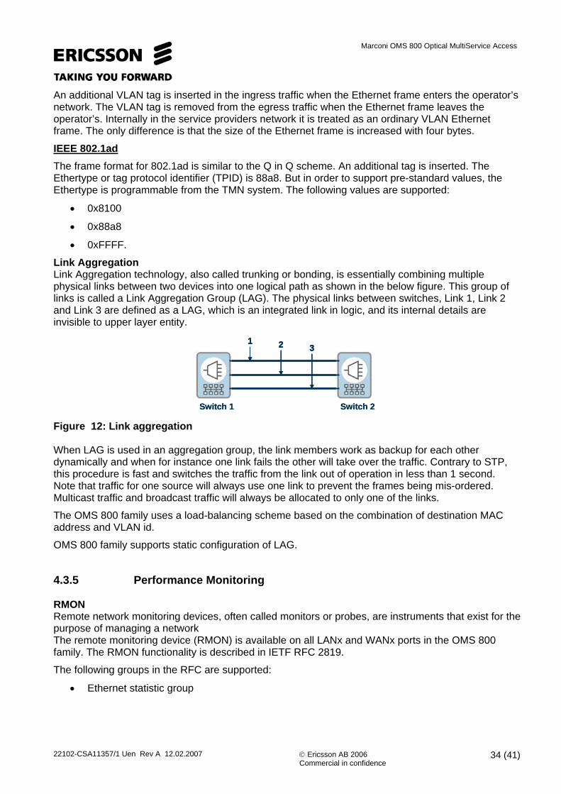
Link Aggregation Link Aggregation technology, also called trunking or bonding, is essentially combining multiple physical links between two devices into one logical path as shown in the below figure. This group of links is called a Link Aggregation Group (LAG). The physical links between switches, Link 1, Link 2 and Link 3 are defined as a LAG, which is an integrated link in logic, and its internal details are invisible to upper layer entity.
1 2 3
Switch 1 Switch 2
1 2 31 2 3
Switch 1 Switch 2 Figure 12: Link aggregation When LAG is used in an aggregation group, the link members work as backup for each other dynamically and when for instance one link fails the other will take over the traffic. Contrary to STP, this procedure is fast and switches the traffic from the link out of operation in less than 1 second. Note that traffic for one source will always use one link to prevent the frames being mis-ordered. Multicast traffic and broadcast traffic will always be allocated to only one of the links.
The OMS 800 family uses a load-balancing scheme based on the combination of destination MAC address and VLAN id.
OMS 800 family supports static configuration of LAG.
4.3.5 Performance Monitoring RMON Remote network monitoring devices, often called monitors or probes, are instruments that exist for the purpose of managing a network The remote monitoring device (RMON) is available on all LANx and WANx ports in the OMS 800 family. The RMON functionality is described in IETF RFC 2819.
The following groups in the RFC are supported:
• Ethernet statistic group
22102-CSA11357/1 Uen Rev A 12.02.2007 © Ericsson AB 2006 Commercial in confidence
34 (41)

Marconi OMS 800 Optical MultiService Access
• History control group • Alarm group • Event group
PM per flow OMS 800 family provides performance monitoring per flow. It is possible to monitor the number of transmitted (i.e. ingress) green, yellow and red frames and octets.
PM data is available for all flows. The available time periods are:
• 15 minutes • 24 hours
The number of historical time periods is:
• 32x15 minutes • 1x24 hours
Port Mirroring OMS 800 family provides the possibility to monitor traffic on a port. Both the received traffic and the transmitted traffic are forwarded to a user-selected port.
4.3.6 Ethernet Physical Layer OMS 800 family supports both electrical and Optical interfaces. Electrical interfaces are either provided by modules inserted into the system or directly as fixed interfaces on the device itself (i.e. OMS 846). Optical interfaces are provided by SFP modules, and following modules are supported by OMS 800 product family;
-24-3/21540-15701 250 000SMF1000BASE-”ZX”
-19-11.5/-31270-13551 250 000SMF1000BASE-LX
-17-11.5/-3.5770-8601 250 00062.5/50um MMF1000BASE-SX
-24.8-15/-81260-1360125 000SMF100BASE-LX10
-31-20/-141270-1380125 00062.5um MMF100BASE-FX
Sensitivity(min) dBm
Launched Power (min/max) dBm
Wavelength nm
Line ratekbps
Fibre typeInterface
Table 6. Ethernet SFP modules.
NA
NA
Cable attenuation dB
RJ-45100100 000100BASE-TX
RJ-4510010 00010BASE-T
Connector typeCable length mLine rate kbpsInterface
NA
NA
Cable attenuation dB
RJ-45100100 000100BASE-TX
RJ-4510010 00010BASE-T
Connector typeCable length mLine rate kbpsInterface
22102-CSA11357/1 Uen Rev A 12.02.2007 © Ericsson AB 2006 Commercial in confidence
35 (41)

Marconi OMS 800 Optical MultiService Access
Table 7. Ethernet Electrical interface characteristics.
4.4 PDH Features OMS 800 family supports PDH interfaces such as E1 (2Mbps), E3 (23Mbps) and T3 (45Mbps). The number of interfaces delivered depends on the product and/or module selected. E1 features E1 interfaces are provided by a fixed number of connectors or by modules inserted in the network element. Additional modules are provided using a high density connector named LFH that provides 32xE1 per connector and optional patch panels with various connector types, both unbalanced 75 Ohm (coaxial connectors) directly on the OMS 846 by 1.0/2.3 or by patch panels with 1.0/2.3 or BT-43, and balanced 120 Ohm can be provided directly on the module/box by RJ-45 connectors or by patch panels with RJ-45 or KRONE connectors. The E1 interfaces provide a number of different services as follows:
• Transparent leased line • Framed leased line • ISDN primary rate access (PRA)
It is possible to configure E1 interfaces individually to support the different services. OMS 800 family includes a special feature to reduce jitter and wander. The pointer processing for the interface is switched off and controlled frame slips are performed if the frequency of the SDH timing is not synchronised to the frequency of the PDH interface. No frame loss, multiframe loss or CRC-4 errors are generated when controlled frame slips are performed. This feature is only supported in the framed leased line and the ISDN PRA modes. The total number of operational modes is five as shown below:
• TRA Transparent leased line • FRA Framed lease line • FRA-FIXED Framed lease line with fixed pointer • PRA ISDN PRA lease line • PRA-FIXED ISDN PRA with fixed pointer
Loopbacks can be activated at line side and terminal side. E3/T3 features E3 and T3 transparent services are provided from the same modules and can be individually programmed. The service is symmetrical in both directions and only supports point-to-point connections. An alarm indication signal (AIS) is inserted toward the network if loss of signal (LOS) is detected from the customer. Connector is coaxial 1.0/2.3. AIS is inserted towards the customer if LOS or other major alarms are detected from the networks. Loopbacks can be activated at line side and terminal side.
22102-CSA11357/1 Uen Rev A 12.02.2007 © Ericsson AB 2006 Commercial in confidence
36 (41)
Marconi OMS 800 Optical MultiService Access
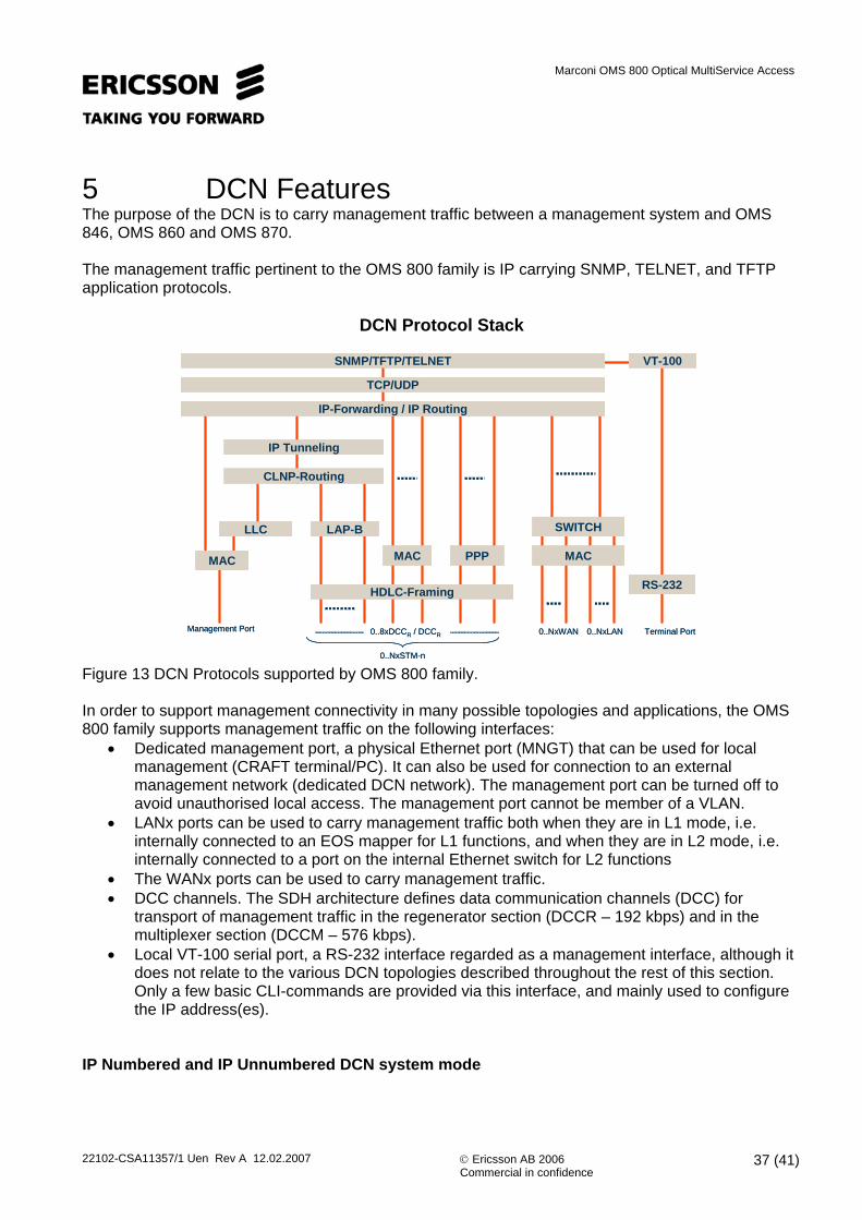
5 DCN Features The purpose of the DCN is to carry management traffic between a management system and OMS 846, OMS 860 and OMS 870. The management traffic pertinent to the OMS 800 family is IP carrying SNMP, TELNET, and TFTP application protocols.
DCN Protocol Stack
SNMP/TFTP/TELNET
IP Tunneling
LLC
MAC
HDLC-Framing RS-232
VT-100
SWITCH
TCP/UDP
IP-Forwarding / IP Routing
CLNP-Routing
LAP-B
MAC PPP MAC
Management Port Terminal Port
0..NxSTM-n
0..NxLAN0..NxWAN0..8xDCCR / DCCR
SNMP/TFTP/TELNET
IP Tunneling
LLC
MAC
HDLC-Framing RS-232
VT-100
SWITCH
TCP/UDP
IP-Forwarding / IP Routing
CLNP-Routing
LAP-B
MAC PPP MAC
Management Port Terminal Port
0..NxSTM-n
0..NxLAN0..NxWAN0..8xDCCR / DCCR
Figure 13 DCN Protocols supported by OMS 800 family. In order to support management connectivity in many possible topologies and applications, the OMS 800 family supports management traffic on the following interfaces:
• Dedicated management port, a physical Ethernet port (MNGT) that can be used for local management (CRAFT terminal/PC). It can also be used for connection to an external management network (dedicated DCN network). The management port can be turned off to avoid unauthorised local access. The management port cannot be member of a VLAN.
• LANx ports can be used to carry management traffic both when they are in L1 mode, i.e. internally connected to an EOS mapper for L1 functions, and when they are in L2 mode, i.e. internally connected to a port on the internal Ethernet switch for L2 functions
• The WANx ports can be used to carry management traffic. • DCC channels. The SDH architecture defines data communication channels (DCC) for
transport of management traffic in the regenerator section (DCCR – 192 kbps) and in the multiplexer section (DCCM – 576 kbps).
• Local VT-100 serial port, a RS-232 interface regarded as a management interface, although it does not relate to the various DCN topologies described throughout the rest of this section. Only a few basic CLI-commands are provided via this interface, and mainly used to configure the IP address(es).
IP Numbered and IP Unnumbered DCN system mode
22102-CSA11357/1 Uen Rev A 12.02.2007 © Ericsson AB 2006 Commercial in confidence
37 (41)

Marconi OMS 800 Optical MultiService Access
The OMS 800 family DCN solution supports two main modes, referred to as system modes:
22102-CSA11357/1 Uen Rev A 12.02.2007 © Ericsson AB 2006 Commercial in confidence
38 (41)
IP Numbered, which means that all management interfaces are allocated with and IP address, or IP Unnumbered, which means that no specific IP address is allocated to the management interfaces. In IP unnumbered mode the OMS 800 uses the same IP address as configured for the system (i.e. the management port). The configuration of the system mode (numbered or unnumbered) applies to the whole network element. OMS 860 and OMS 870 can also serve as a gateway from an external DCN to other OMS860 and OMS 870 nodes in the SDH network. IP forwarding IP forwarding implies that the device can have multiple IP interfaces, i.e. that it can be a multi homed IP host. The OMS 800 family supports the ability to forward IP datagrams between interfaces supported by routing protocols (RIP, OSPF). IP forwarding is SW based (low capacity) and intended for management traffic only. External DCN “External DCN” means that the management station connects to the OMS 800 family member via a separate DCN by using the physical management port on the device. Both IP/Eternet and CLNP/802.x are supported. In-band DCN OMS 800 family can be configured to carry management traffic together with customer traffic, giving the possibility to reach the device in topologies where the SDH network, or part of it, is owned by a different operator that does not allow a third party to use the DCC channel. In-band DCN is supported by LAN ports in the device and operation is dependent on whether the ports are in L1- or L2-mode. A LANx port in L2 mode is connected to a switch, and may carry in-band management traffic if an IP-address is assigned to the port, or to the VLAN to which it belongs. User traffic is separated by dedicated LANx/WANx ports or dedicated VLANs for management traffic. LANx ports in L1 mode - the management traffic is identified by means of a proprietary Ericsson MAC address. OSI/DCC DCN In this operational mode, OMS 800 family IP-based management traffic will be transported through the DCC channels of a general mutli-vendor SDH network by means of standard OSI-protocols at Layer 2 and Layer 3. All the interfaces of the device that have the OSI option enabled will be connected to the internal CLNP router. This implies that also third party DCC-traffic will be routed across the OMS 800 family CLNP router. PPP/DCC DCN In the PPP/DCN mode management IP-traffic is carried in PPP over the SDH DCC channels. DCC Transparency Features To overcome 3rd. party vendors proprietary or uncommonly used protocols for management connectivity, OMS 800 family has the ability to ‘transparently’ forward the management signals

Marconi OMS 800 Optical MultiService Access
through their nodes. This is typically useful when OMS 800 family is part of a multi-vendor ring configuration.
22102-CSA11357/1 Uen Rev A 12.02.2007 © Ericsson AB 2006 Commercial in confidence
39 (41)
If the DCC channels in the network is heavily loaded then optional channels for transport is recommended. Protection If the in-band DCN option is used on a protected SDH path the switchover will be transparent for higher levels.

Marconi OMS 800 Optical MultiService Access
6 Technical Specifications
6.1 Mechanical design and requirements The OMS 846, OMS 860 and OMS 870 are housed in a shelf that is compatible with “19” or ETSI equipment practice. The shelf comprises a sub-rack with room for an aggregate module that may have fixed tributary interfaces or for some devices have optional hot insertion tributary interface modules and a fan module.
The height of the unit is 1 U (44.45 mm).
It is possible to mount one single shelf including cable terminating and cable handling facilities within an enclosure with external dimensions:
Width: 450 mm Height: 44.45 mm Depth: 280 mm
The mechanical design of the OMS 800 family meets the requirements of EN/IEC 60950. The OMS 800 family can also be used as a desktop solution or wall mounted using dedicated brackets.
The total weight of the OMS 846 and 860base unit is less than 3,5 Kg, and for OMS 860 fully equipped less than 4 Kg. The total weight of the OMS 870 fully equipped does not exceed 5 kg.
6.2 Safety OMS 846, 860 and 870 are designed not to cause any harm or danger to personnel installing, maintaining or operating the equipment, and not to create any damage to the network or other equipment connected to it.
The OMS 800 family is designed to meet European safety standards such as:
Electrical safety:
• EN 60950
Optical Safety :
• EN 60825 (Classification and optical safety)
6.3 Environment
6.3.1 Electromagnetic compatibility (EMC) The OMS 846, 860 and 870 meet the requirement for EMC as specified in EN 300 386 for use in both inside Telecom Centres and outside Telecom Centres.
22102-CSA11357/1 Uen Rev A 12.02.2007 © Ericsson AB 2006 Commercial in confidence
40 (41)

Marconi OMS 800 Optical MultiService Access
6.3.2 Climatic and Mechanical Environment
22102-CSA11357/1 Uen Rev A 12.02.2007 © Ericsson AB 2006 Commercial in confidence
41 (41)
The OMS 846, 860 and 870 meet the requirements for operational, transportation and storage environment as specified in ETS 300 019, and are classified as follows;
Requirement Specification Classes Temp Range
Storage ETS 300 019-2-1
Class 1.1 -40 to + 70 0C
Transportation ETS 300 019-2-2
Class 2.1, 2.2 and 2.3
-25 to + 70 0C
Operational (mandatory)
ETS 300 019-2-3
Class 3.1, 3.1E and 3.2
- 5 to +45 0C
Table 4. Environmental classifications
- End of Document -
Related Documents