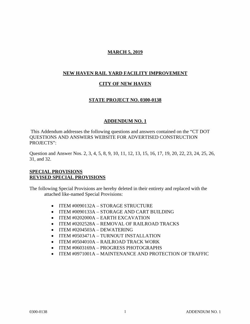
0300-0138 ADDENDUM NO. 1 MARCH 5, 2019 NEW HAVEN RAIL YARD FACILITY IMPROVEMENT CITY OF NEW HAVEN STATE PROJECT NO. 0300-0138 ADDENDUM NO. 1 This Addendum addresses the following questions and answers contained on the “CT DOT QUESTIONS AND ANSWERS WEBSITE FOR ADVERTISED CONSTRUCTION PROJECTS”: Question and Answer Nos. 2, 3, 4, 5, 8, 9, 10, 11, 12, 13, 15, 16, 17, 19, 20, 22, 23, 24, 25, 26, 31, and 32. SPECIAL PROVISIONS REVISED SPECIAL PROVISIONS The following Special Provisions are hereby deleted in their entirety and replaced with the attached like-named Special Provisions: ITEM #0090132A – STORAGE STRUCTURE ITEM #0090133A – STORAGE AND CART BUILDING ITEM #0202000A – EARTH EXCAVATION ITEM #0202528A – REMOVAL OF RAILROAD TRACKS ITEM #0204503A – DEWATERING ITEM #0503471A – TURNOUT INSTALLATION ITEM #0504010A – RAILROAD TRACK WORK ITEM #0603169A – PROGRESS PHOTOGRAPHS ITEM #0971001A – MAINTENANCE AND PROTECTION OF TRAFFIC 1

Welcome message from author
This document is posted to help you gain knowledge. Please leave a comment to let me know what you think about it! Share it to your friends and learn new things together.
Transcript
0300-0138 ADDENDUM NO. 1
MARCH 5, 2019
NEW HAVEN RAIL YARD FACILITY IMPROVEMENT
CITY OF NEW HAVEN
STATE PROJECT NO. 0300-0138
ADDENDUM NO. 1
This Addendum addresses the following questions and answers contained on the “CT DOT QUESTIONS AND ANSWERS WEBSITE FOR ADVERTISED CONSTRUCTION PROJECTS”:
Question and Answer Nos. 2, 3, 4, 5, 8, 9, 10, 11, 12, 13, 15, 16, 17, 19, 20, 22, 23, 24, 25, 26, 31, and 32.
SPECIAL PROVISIONS REVISED SPECIAL PROVISIONS
The following Special Provisions are hereby deleted in their entirety and replaced with the
attached like-named Special Provisions:
ITEM #0090132A – STORAGE STRUCTURE ITEM #0090133A – STORAGE AND CART BUILDING ITEM #0202000A – EARTH EXCAVATION ITEM #0202528A – REMOVAL OF RAILROAD TRACKS ITEM #0204503A – DEWATERING ITEM #0503471A – TURNOUT INSTALLATION ITEM #0504010A – RAILROAD TRACK WORK ITEM #0603169A – PROGRESS PHOTOGRAPHS ITEM #0971001A – MAINTENANCE AND PROTECTION OF TRAFFIC
1
0300-0138 ADDENDUM NO. 1
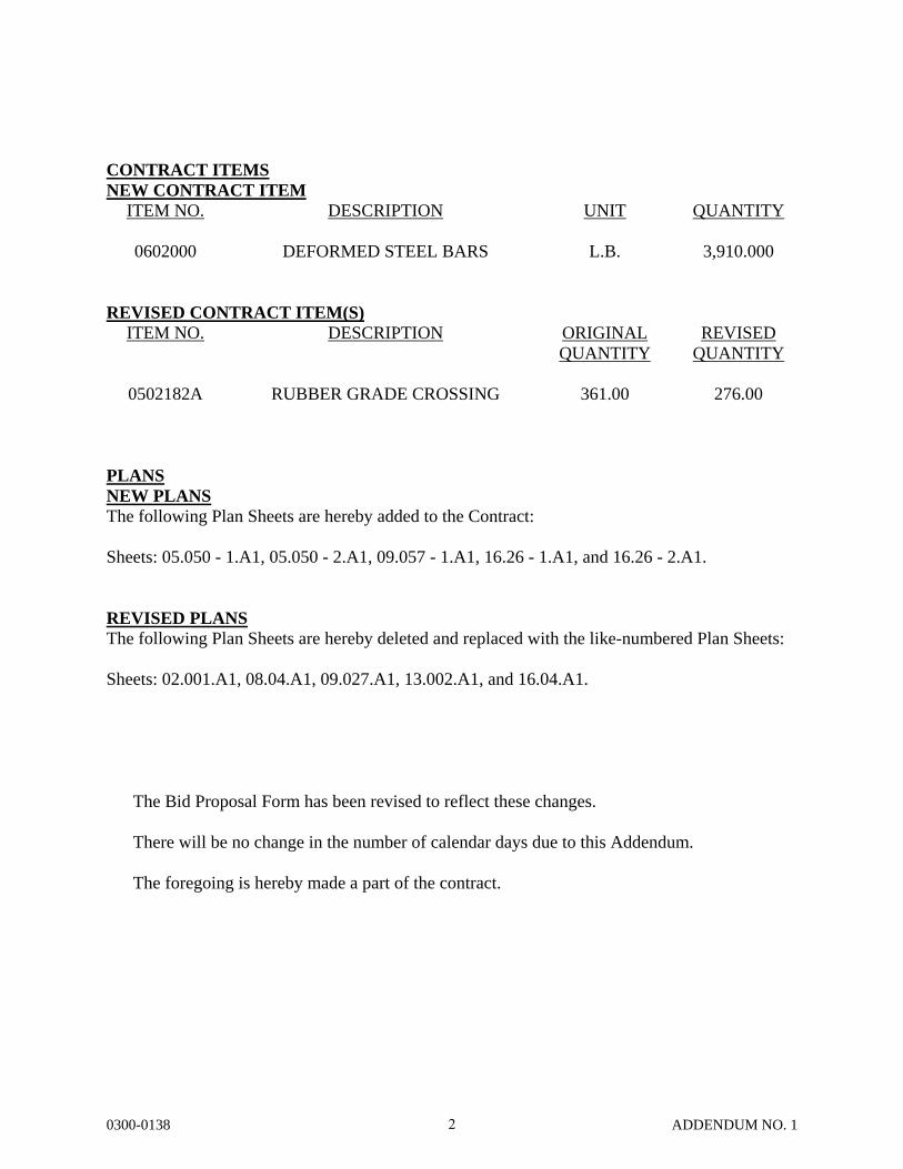
CONTRACT ITEMS NEW CONTRACT ITEM
ITEM NO.
0602000
DESCRIPTION
DEFORMED STEEL BARS
UNIT
L.B.
QUANTITY
3,910.000
REVISED CONTRACT ITEM(S)
ITEM NO.
0502182A
DESCRIPTION
RUBBER GRADE CROSSING
ORIGINAL QUANTITY
361.00
REVISED QUANTITY
276.00
PLANS NEW PLANS The following Plan Sheets are hereby added to the Contract: Sheets: 05.050 - 1.A1, 05.050 - 2.A1, 09.057 - 1.A1, 16.26 - 1.A1, and 16.26 - 2.A1. REVISED PLANS The following Plan Sheets are hereby deleted and replaced with the like-numbered Plan Sheets:
Sheets: 02.001.A1, 08.04.A1, 09.027.A1, 13.002.A1, and 16.04.A1. The Bid Proposal Form has been revised to reflect these changes. There will be no change in the number of calendar days due to this Addendum. The foregoing is hereby made a part of the contract.
2
Rev. Date 2/27/19
0300-0138 ITEM#0090132A ADDENDUM NO. 1
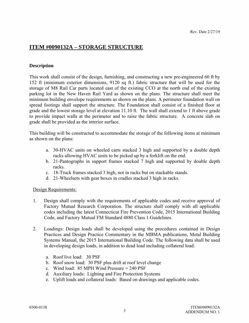
ITEM #0090132A – STORAGE STRUCTURE Description This work shall consist of the design, furnishing, and constructing a new pre-engineered 60 ft by 152 ft (minimum exterior dimensions, 9120 sq ft.) fabric structure that will be used for the storage of M8 Rail Car parts located east of the existing CCO at the north end of the existing parking lot in the New Haven Rail Yard as shown on the plans. The structure shall meet the minimum building envelope requirements as shown on the plans. A perimeter foundation wall on spread footings shall support the structure. The Foundation shall consist of a finished floor at grade and the lowest storage level at elevation 11.10 ft. The wall shall extend to 1 ft above grade to provide impact walls at the perimeter and to raise the fabric structure. A concrete slab on grade shall be provided as the interior surface. This building will be constructed to accommodate the storage of the following items at minimum as shown on the plans:
a. 30-HVAC units on wheeled carts stacked 3 high and supported by a double depth racks allowing HVAC units to be picked up by a forklift on the end.
b. 21-Pantographs in support frames stacked 7 high and supported by double depth racks.
c. 18-Truck frames stacked 3 high, not in racks but on stackable stands. d. 21-Wheelsets with gear boxes in cradles stacked 3 high in racks.
Design Requirements:
1. Design shall comply with the requirements of applicable codes and receive approval of
Factory Mutual Research Corporation. The structure shall comply with all applicable codes including the latest Connecticut Fire Prevention Code, 2015 International Building Code, and Factory Mutual FM Standard 4880 Class 1 Guidelines.
2. Loadings: Design loads shall be developed using the procedures contained in Design
Practices and Design Practice Commentary in the MBMA publications, Metal Building Systems Manual, the 2015 International Building Code. The following data shall be used in developing design loads, in addition to dead load including collateral load:
a. Roof live load: 30 PSF b. Roof snow load: 30 PSF plus drift at roof level change c. Wind load: 85 MPH Wind Pressure = 240 PSF d. Auxiliary loads: Lighting and Fire Protection Systems e. Uplift loads and collateral loads: Based on drawings and applicable codes.
3

Rev. Date 2/27/19
0300-0138 ITEM#0090132A ADDENDUM NO. 1
3. The structural drawings are for bidding only and not for construction. All footing design has been based on the design criteria contained herein and on assumed loads and stiffness of pre-engineered structural members. Contractor shall not start foundation reinforcing shop drawings until he has submitted actual superstructure reactions to the Engineer and revised foundation detail drawings accommodating these reactions have been issued by the Engineer. Structural Contractor shall coordinate with Foundation Contractor.
4. Framing and Structural Members:
a. Structural steel members shall be designed in accordance with AISC publication.
Specification for the Design, Fabrication, and Erection of Structural Steel for Buildings.
b. Structural, cold-formed, steel framing members shall be designed in accordance with AISI publication. Specification for the Design of Cold-Formed Steel Structural Members.
c. Framed openings shall be designed to structurally replace the covering and framing
displaced.
d. Welding of steel shall conform to the requirements of AWS Dl.1 and D1.3. e. Wind uplift ratings for standing seam roof system: Obtain from UL testing conducted
in accordance with “Tests for Wind Uplift Resistance of Roof Assemblies”, UL580. Specific information shall be obtained in UL “Building Material Directory” and applicable state codes.
5. The following additional building requirements and standards shall be met:
a. An overhead rollup door (20 ft x 16 ft) with overhead electrical operator and a 36”
wide personnel door on the southerly and westerly walls. All doors shall be equipped with MNR approved locks. See plans for details.
b. A two foot wide zone on all sides that allows for the building frame and fabric.
c. Positive drainage away from the structure to promote surface runoff as shown on the plans.
d. The Connecticut Building Code (paragraph 3102.3.1.2) requires that the fabric be flameproof.
e. Fabric membrane shall be water and mildew resistant, insect proof, withstand extreme climatic variations, and contain UV inhibitors to reduce degradation by the sun’s rays.
f. Interior warehouse lighting, exterior egress lighting and lighted exit signs must be provided to meet all relevant codes. Lighted exit signs shall be equipped with battery
4
Rev. Date 2/27/19
0300-0138 ITEM#0090132A ADDENDUM NO. 1
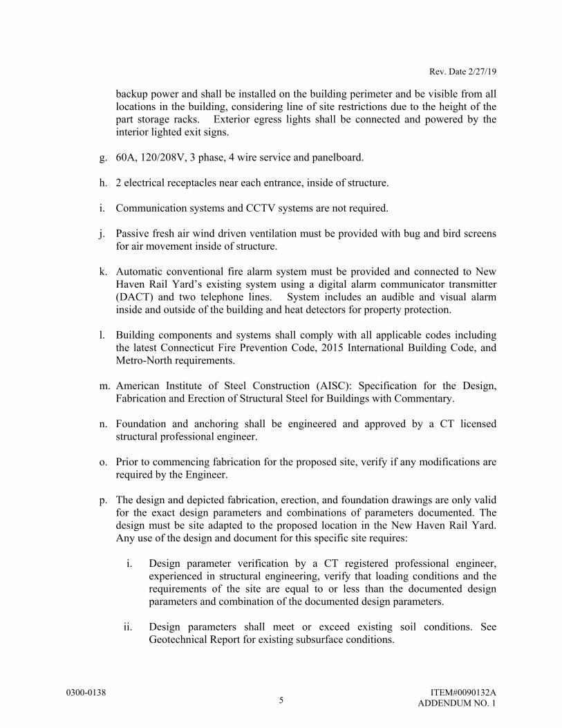
backup power and shall be installed on the building perimeter and be visible from all locations in the building, considering line of site restrictions due to the height of the part storage racks. Exterior egress lights shall be connected and powered by the interior lighted exit signs.
g. 60A, 120/208V, 3 phase, 4 wire service and panelboard.
h. 2 electrical receptacles near each entrance, inside of structure.
i. Communication systems and CCTV systems are not required.
j. Passive fresh air wind driven ventilation must be provided with bug and bird screens for air movement inside of structure.
k. Automatic conventional fire alarm system must be provided and connected to New Haven Rail Yard’s existing system using a digital alarm communicator transmitter (DACT) and two telephone lines. System includes an audible and visual alarm inside and outside of the building and heat detectors for property protection.
l. Building components and systems shall comply with all applicable codes including the latest Connecticut Fire Prevention Code, 2015 International Building Code, and Metro-North requirements.
m. American Institute of Steel Construction (AISC): Specification for the Design, Fabrication and Erection of Structural Steel for Buildings with Commentary.
n. Foundation and anchoring shall be engineered and approved by a CT licensed structural professional engineer.
o. Prior to commencing fabrication for the proposed site, verify if any modifications are required by the Engineer.
p. The design and depicted fabrication, erection, and foundation drawings are only valid for the exact design parameters and combinations of parameters documented. The design must be site adapted to the proposed location in the New Haven Rail Yard. Any use of the design and document for this specific site requires:
i. Design parameter verification by a CT registered professional engineer,
experienced in structural engineering, verify that loading conditions and the requirements of the site are equal to or less than the documented design parameters and combination of the documented design parameters.
ii. Design parameters shall meet or exceed existing soil conditions. See
Geotechnical Report for existing subsurface conditions.
5
Rev. Date 2/27/19
0300-0138 ITEM#0090132A ADDENDUM NO. 1
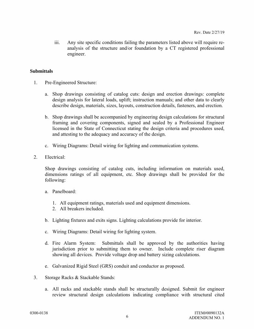
iii. Any site specific conditions failing the parameters listed above will require re-analysis of the structure and/or foundation by a CT registered professional engineer.
Submittals
1. Pre-Engineered Structure:
a. Shop drawings consisting of catalog cuts: design and erection drawings: complete design analysis for lateral loads, uplift; instruction manuals; and other data to clearly describe design, materials, sizes, layouts, construction details, fasteners, and erection.
b. Shop drawings shall be accompanied by engineering design calculations for structural
framing and covering components, signed and sealed by a Professional Engineer licensed in the State of Connecticut stating the design criteria and procedures used, and attesting to the adequacy and accuracy of the design.
c. Wiring Diagrams: Detail wiring for lighting and communication systems.
2. Electrical:
Shop drawings consisting of catalog cuts, including information on materials used, dimensions ratings of all equipment, etc. Shop drawings shall be provided for the following:
a. Panelboard:
1. All equipment ratings, materials used and equipment dimensions. 2. All breakers included.
b. Lighting fixtures and exits signs. Lighting calculations provide for interior.
c. Wiring Diagrams: Detail wiring for lighting system. d. Fire Alarm System: Submittals shall be approved by the authorities having
jurisdiction prior to submitting them to owner. Include complete riser diagram showing all devices. Provide voltage drop and battery sizing calculations.
e. Galvanized Rigid Steel (GRS) conduit and conductor as proposed.
3. Storage Racks & Stackable Stands:
a. All racks and stackable stands shall be structurally designed. Submit for engineer
review structural design calculations indicating compliance with structural cited
6
Rev. Date 2/27/19
0300-0138 ITEM#0090132A ADDENDUM NO. 1
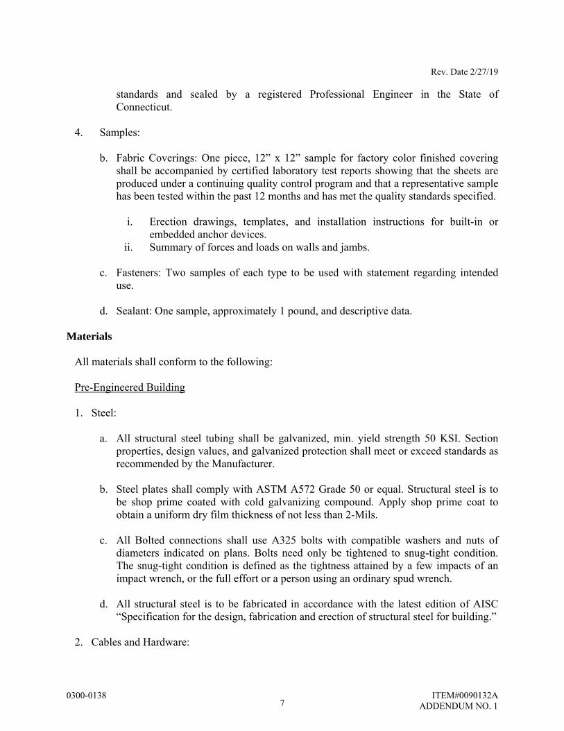
standards and sealed by a registered Professional Engineer in the State of Connecticut.
4. Samples:
b. Fabric Coverings: One piece, 12” x 12” sample for factory color finished covering shall be accompanied by certified laboratory test reports showing that the sheets are produced under a continuing quality control program and that a representative sample has been tested within the past 12 months and has met the quality standards specified.
i. Erection drawings, templates, and installation instructions for built-in or
embedded anchor devices. ii. Summary of forces and loads on walls and jambs.
c. Fasteners: Two samples of each type to be used with statement regarding intended
use.
d. Sealant: One sample, approximately 1 pound, and descriptive data.
Materials
All materials shall conform to the following:
Pre-Engineered Building 1. Steel:
a. All structural steel tubing shall be galvanized, min. yield strength 50 KSI. Section
properties, design values, and galvanized protection shall meet or exceed standards as recommended by the Manufacturer.
b. Steel plates shall comply with ASTM A572 Grade 50 or equal. Structural steel is to
be shop prime coated with cold galvanizing compound. Apply shop prime coat to obtain a uniform dry film thickness of not less than 2-Mils.
c. All Bolted connections shall use A325 bolts with compatible washers and nuts of
diameters indicated on plans. Bolts need only be tightened to snug-tight condition. The snug-tight condition is defined as the tightness attained by a few impacts of an impact wrench, or the full effort or a person using an ordinary spud wrench.
d. All structural steel is to be fabricated in accordance with the latest edition of AISC
“Specification for the design, fabrication and erection of structural steel for building.”
2. Cables and Hardware:
7
Rev. Date 2/27/19
0300-0138 ITEM#0090132A ADDENDUM NO. 1
a. All cable shall be galvanized steel, multipurpose, 7 x 7 (≤ 1/4” Dia.) or 7 x 19 (5/16” & 3/8” Dia.) or 6 x 26 (1/2” dia.) class strand core commercial grade, or diameter indicated, unless otherwise noted.
b. Cable sleeves shall be installed per manufacturer’s recommendations.
c. Use thimbles with cable sleeves in all loop-end applications.
d. Tension cables at turnbuckle to taut condition (straight and not slack or loose).
e. Tighten cables sequentially to avoid twisting or deforming structural elements during erection. Recheck previously tightened cables until all cables achieve taut condition.
3. Electric Service:
a. 60A, 120/208V, 3 phase, 4 wire electrical service shall be provided to the warehouse
location from the location as shown on the plans. The contractor shall provide minimum (4) #2 & (1) #6 ground wire in 3” rigid galvanized steel conduit below ground. The service feeder indicated is a minimum required and will vary based on the determined origin of the electric service and voltage drop calculation. The engineer’s approval will be required for final feeder sizing. (1) 60A, 3 pole breaker shall be provided in the selected origin panelboard. The type and rating of the circuit breaker shall match existing. (1) 100A bus, 30 pole panelboard shall be provided within the warehouse space. The panelboard shall be equipped with a 60A main circuit breaker, (22) 20A, single pole circuit breakers and (8) spare spaces. The short circuit rating shall match that of the feeder breaker.
b. There shall be (4) 20A, 120V GFI, duplex receptacles provided with weatherproof
covers. The receptacles shall be located on the inside of the building, 2 on either side of the building near the entryways.
c. Electrical components and systems shall comply with all applicable codes including
the Connecticut Fire Prevention and Building Codes, and Metro-North requirements for approval by Factory Mutual Research Corporation of specific building systems.
d. Other applicable codes include but are not limited to the following:
NFPA 70 – National Electric Code NFPA 72 – National Fire Alarm and Signaling code NFPA 101 – Life Safety Code
4. Lighting:
a. Interior lighting; High-bay LED style, rugged die-cast aluminum housing UL rated
for wet location, low temperature use. Provide with 6’-0” cord, hook and 15A twist lock plug. Each fixture shall have an integral 360 degree motion sensor on/off wet location. Lighting levels provided shall be 25-30 foot candles with an average to
8
Rev. Date 2/27/19
0300-0138 ITEM#0090132A ADDENDUM NO. 1
minimum ratio of 3:1. Source shall be 4000k with an 80 CRI. Optics, .375” thick borosilicate glass that is silicone rubber gasketed. ¾” NPS threaded hub standard that is suitable for pendant, hook or loop mounting. An interior receptacle for fixture plug in controlled via toggle switch shall be provided for manual override and shall control all lighting fixtures.
b. Emergency lighting drivers (batteries) shall be provided within a certain amount of
interior high bay fixtures such that in the event of power failure 1fc average is provided at the floor level and no spot on the floor shall be less than .1fc (in accordance with NFPA 101).
c. Exterior Egress Lighting: Located above each egress man door (2 total) on the
exterior, an emergency wall mount style fixture shall be provided. The fixture shall be LED type rated for exterior, low temperature use. The fixture shall be equipped with an emergency battery. Source shall 4000k with an 80 CRI.
5. Exit Signage:
a. Access to exits must be clearly marked by visible signs. At a minimum, emergency
exit signage shall be provided above each egress man door (2 total) on the interior side. Additional exit signage and/or directional signage shall be provided as required when signage above doors is not visible due to location of storage racks and equipment stands. The fixture shall be LED type rated for exterior, low temperature use. The fixture shall be equipped with an emergency battery and shall meet the requirements of NFPA 101.
6. Fire Alarm System:
a. A conventional fire alarm system meeting all requirements of NFPA 72 shall be
provided. The system shall be connected to New Haven Rail Yard’s existing system using form C contacts to transmit alarm, trouble and supervisory signals for remote monitoring. This specification includes wiring from this FACP to the FACP in the CCO building for remote monitoring. Provide surge suppression on each signal line between buildings. FACP shall also be supplied with DACT and internet monitoring modules for future connections if needed. The method of connection and monitoring of the new system shall be coordinated with the owner and must be compatible with the existing FACP in the CCO building. The existing FACP in the CCO building shall be programmed to monitor the signals from this FACP. At a minimum the design shall include (2) pull stations at each exit door, horn strobe units to provide proper audio/visual coverage, and rate of rise type heat detectors for 100% detection coverage. Also included shall be a weatherproof audible and visual alarm outside of the building. All wiring shall be class B. The FACP shall be housed in a NEMA 3R enclosure that provides heating and cooling to meet the operating range of the installed FACP. Any monitor modules for addressable devices must also be housed in a separate NEMA 3R enclosure that provides heating and cooling to meet the operating range of the installed monitor modules.
9
Rev. Date 2/27/19
0300-0138 ITEM#0090132A ADDENDUM NO. 1
b. Manufacturers: Subject to compliance with requirements, manufacturers offering
products that may be incorporated into the Work, include, but are not limited to, the following:
i. Fire Lite Alarms MS-5UD by Honeywell.
ii. Faraday by Siemens. iii. Simplex Grinnell by Tyco. iv. Or approved equal.
c. Heat Detectors: Single circuit fixed temperature with rate of rise detection, 135 deg
F. Coverage shall be derated as specified for ceiling height per NFPA 72. System Sensor model 5601P or approved equal. Must be compatible with FACP.
d. Manual Pull Stations: Non-coded, red dual-action manually activated signaling boxes meeting ADA 5 lb. maximum pull-force. System Sensor BG-12 or approved equal.
e. Notification Appliances: Red Horn/strobes, synchronized on Class B circuits, Listed to UL 1971 and UL 464 and shall operate on a non-coded power supply with field selectable candela settings. System Sensor L-series P2RL or approved equal.
Electrical Materials:
1. General materials and workmanship:
a. Materials and apparatus required for the work shall be new, of first-class quality, and
shall be furnished, delivered, erected, connected, finished in every detail, and shall be so selected and arranged as to fit properly into the building spaces in compliance with all requirements.
b. Manufacturer's catalog numbers listed are not necessarily complete. Products provided shall be a standard product which has a history of successful installation and operation for a minimum period of two years. Prototype or custom made equipment is not acceptable unless so specified.
c. Manufacturer's instructions shall be obtained and used for the installation of all equipment and devices where such manufacturers' instructions are available.
2. Conductors and cables:
a. Available Manufacturers: Subject to compliance with requirements, manufacturers
offering products that may be incorporated into the Work include, but are not limited to, the following:
i. Alpha Wire Company. ii. American Insulated Wire Corp.; a Leviton Company.
10
Rev. Date 2/27/19
0300-0138 ITEM#0090132A ADDENDUM NO. 1
iii. Belden Inc. iv. Cerro Wire LLC. v. General Cable Corporation.
vi. Senator Wire & Cable Company. vii. Southwire Company.
b. Copper Conductors: Comply with NEMA WC 70/ICEA S-95-658.
c. Conductor Insulation: Comply with NEMA WC 70/ICEA S-95-65 and type RHW-3.
d. Multiconductor Cable: Comply with NEMA WC 70 for metal-clad cable, Type MC with ground wire.
e. MC Metal Clad Cable: 90° C dry THHN copper conductors, maximum voltage 600V.
Include green insulated grounding conductor. Steel or aluminum armor.
3. Connectors and splices: a. Description: Factory-fabricated connectors and splices of size, ampacity rating,
material, type, and class for application and service indicated.
b. Available Manufacturers: Subject to compliance with requirements, manufacturers offering products that may be incorporated into the Work include, but are not limited to, the following:
i. AFC Cable Systems, Inc. ii. Hubbell Power Systems, Inc.
iii. O-Z/Gedney; EGS Electrical Group LLC. iv. 3M; Electrical Products Division. v. Tyco Electronics Corp.
4. Conductor Material Applications:
a. Feeders: Copper. Solid for No. 10 AWG and smaller; stranded for No. 8 AWG and
larger. b. Branch Circuits: Copper. Solid for No. 10 AWG and smaller; stranded for No. 8
AWG and larger.
5. Conductor insulation and multiconductor cable applications: a. Service Entrance: Type THWN, single conductors in raceway.
b. Feeders: Type THHN-THWN, single conductors in raceway.
c. Exposed Branch Circuits: Type THHN-THWN, single conductors in raceway.
11
Rev. Date 2/27/19
0300-0138 ITEM#0090132A ADDENDUM NO. 1
d. Class 1 Control Circuits: Type THHN-THWN, in raceway. e. Class 2 Control Circuits: Type THHN-THWN, in raceway.
f. Feeders and branch circuits underground in conduits or duct banks and outside the
perimeter of the building: type RHW-2 single conductors in raceway.
6. Conductor identification materials: a. Color-Coding Conductor Tape: Colored, self-adhesive vinyl tape not less than 3 mils
(0.08 mm) thick by 1 to 2 inches (25 to 50 mm) wide.
b. Self-Adhesive Vinyl Labels: Preprinted, flexible label laminated with a clear, weather- and chemical-resistant coating and matching wraparound adhesive tape for securing ends of legend label.
c. Snap-Around Labels: Slit, pretensioned, flexible, preprinted, color-coded acrylic sleeve, with diameter sized to suit diameter of raceway or cable it identifies and to stay in place by gripping action.
d. Snap-Around, Color-Coding Bands: Slit, pretensioned, flexible, solid-colored acrylic sleeve, 2 inches (50 mm) long, with diameter sized to suit diameter of raceway or cable it identifies and to stay in place by gripping action.
e. Marker Tapes: Vinyl or vinyl-cloth, self-adhesive wraparound type, with circuit identification legend machine printed by thermal transfer or equivalent process.
f. Write-On Tags: Polyester tag, 0.010 inch (0.25 mm) thick, with corrosion-resistant grommet and cable tie for attachment to conductor or cable.
g. Marker for Tags: Permanent, waterproof, black ink marker recommended by tag manufacturer.
7. Equipment Identification Labels:
a. Self-Adhesive, Engraved, Laminated Acrylic, or Melamine Label: Adhesive backed
letters on a dark-gray background. Minimum letter height shall be 3/8 inch (10 mm).
b. Stenciled Legend: In nonfading, waterproof, black ink or paint. Minimum letter height shall be 1 inch (25 mm).
8. Cable Ties:
a. General-Purpose Cable Ties: Fungus inert, self-extinguishing, one piece, self-
locking, Type 6/6 nylon.
12

Rev. Date 2/27/19
0300-0138 ITEM#0090132A ADDENDUM NO. 1
i. Minimum Width: 3/16 inch (5 mm).
ii. Tensile Strength at 73 deg F (23 deg C), According to ASTM D 638: 12,000 psi (82.7 MPa).
iii. Temperature Range: Minus 40 to plus 185 deg F (Minus 40 to plus 85 deg C). iv. Color: Black except where used for color-coding.
9. Miscellaneous Identification Products:
a. Fasteners for Labels and Signs: Self-tapping, stainless-steel screws or stainless-steel
machine screws with nuts and flat and lock washers. Panelboards
1. Enclosures: Flush- and surface-mounted cabinets.
a. Rated for environmental conditions at installed location.
i. Indoor Dry and Clean Locations: NEMA 250, Type 1.
ii. Outdoor Locations: NEMA 250, Type 3R.
b. Front: Secured to box with concealed trim clamps. For surface-mounted fronts, match box dimensions; for flush-mounted fronts, overlap box.
c. Hinged Front Cover: Entire front trim hinged to box and with standard door within hinged trim cover.
d. Skirt for Surface-Mounted Panelboards: Same gauge and finish as panelboard front
with flanges for attachment to panelboard, wall, and ceiling or floor.
e. Gutter Extension and Barrier: Same gauge and finish as panelboard enclosure; integral with enclosure body. Arrange to isolate individual panel sections.
f. Finishes:
i. Panels and Trim: Steel, factory finished immediately after cleaning and
pretreating with manufacturer's standard two-coat, baked-on finish consisting of prime coat and thermosetting topcoat.
ii. Back Boxes: Galvanized steel.
g. Directory Card: Inside panelboard door, mounted in metal frame with transparent protective cover.
h. Incoming Mains Location: Top and bottom. i. Phase, Neutral, and Ground Buses:
13
Rev. Date 2/27/19
0300-0138 ITEM#0090132A ADDENDUM NO. 1
i. Material: Copper.
ii. Equipment Ground Bus: Adequate for feeder and branch-circuit equipment grounding conductors; bonded to box.
j. Conductor Connectors: Suitable for use with conductor material and sizes.
i. Material: Hard-drawn copper, 98 percent conductivity. ii. Main and Neutral Lugs: Compression type.
iii. Ground Lugs and Bus-Configured Terminators: Compression type. iv. Feed-Through Lugs: Compression type, suitable for use with conductor
material. Locate at opposite end of bus from incoming lugs or main device. v. Subfeed (Double) Lugs: Compression type suitable for use with conductor
material. Locate at same end of bus as incoming lugs or main device.
k. Service Equipment Label: NRTL labeled for use as service equipment for panelboards with one or more main service disconnecting and overcurrent protective devices.
l. Future Devices: Mounting brackets, bus connections, filler plates, and necessary appurtenances required for future installation of devices.
m. Panelboard Short-Circuit Current Rating: Fully rated to interrupt symmetrical short-circuit current available at terminals.
2. Lighting and Appliance Branch-circuit Panelboards:
a. Basis-of-Design Product: Subject to compliance with requirements, provide Square
D; a brand of Schneider Electric, or comparable product by one of the following:
i. Eaton Electrical Inc.; Cutler-Hammer Business Unit. ii. General Electric Company; GE Consumer & Industrial - Electrical
Distribution. iii. Siemens Energy & Automation, Inc.
b. Panelboards: NEMA PB 1, lighting and appliance branch-circuit type.
c. Mains: Circuit breaker or lugs only.
d. Branch Overcurrent Protective Devices: Bolt-on circuit breakers, replaceable without
disturbing adjacent units.
e. Doors: Concealed hinges; secured with flush latch with tumbler lock; keyed alike.
3. Disconnecting and Overcurrent Protective Devices:
14
Rev. Date 2/27/19
0300-0138 ITEM#0090132A ADDENDUM NO. 1
a. Molded-Case Circuit Breaker (MCCB): Comply with UL 489, with interrupting capacity to meet available fault currents.
i. Thermal-Magnetic Circuit Breakers: Inverse time-current element for low-
level overloads, and instantaneous magnetic trip element for short circuits. Adjustable magnetic trip setting for circuit-breaker frame sizes 250 A and larger.
ii. Electronic trip circuit breakers with rms sensing; field-replaceable rating plug or field-replicable electronic trip; and the following field-adjustable settings:
1) Instantaneous trip. 2) Long- and short-time pickup levels. 3) Long- and short-time time adjustments. 4) Ground-fault pickup level, time delay, and I2t response.
iii. Current-Limiting Circuit Breakers: Frame sizes 400 A and smaller; let-
through ratings less than NEMA FU 1, RK-5.
iv. GFCI Circuit Breakers: Single- and two-pole configurations with Class A ground-fault protection (6-mA trip).
v. Ground-Fault Equipment Protection (GFEP) Circuit Breakers: Class B ground-fault protection (30-mA trip).
vi. Molded-Case Circuit-Breaker (MCCB) Features and Accessories:
1) Standard frame sizes, trip ratings, and number of poles. 2) Lugs: Compression style, suitable for number, size, trip ratings, and
conductor materials. 3) Application Listing: Appropriate for application; Type SWD for
switching fluorescent lighting loads; Type HID for feeding fluorescent and high-intensity discharge (HID) lighting circuits.
4) Ground-Fault Protection: Integrally mounted relay and trip unit with adjustable pickup and time-delay settings, push-to-test feature, and ground-fault indicator.
5) Shunt Trip: 120V trip coil energized from separate circuit, set to trip at 55 percent of rated voltage.
6) Undervoltage Trip: Set to operate at 35 to 75 percent of rated voltage without intentional time delay.
7) Auxiliary Contacts: One SPDT switch with "a" and "b" contacts; "a" contacts mimic circuit-breaker contacts and "b" contacts operate in reverse of circuit-breaker contacts.
8) Multipole units enclosed in a single housing or factory assembled to operate as a single unit.
9) Handle Padlocking Device: Fixed attachment, for locking circuit-breaker handle in on or off position.
15
Rev. Date 2/27/19
0300-0138 ITEM#0090132A ADDENDUM NO. 1
10) Handle Clamp: Loose attachment, for holding circuit-breaker handle in on position.
4. Panelboard Suppressors (spd): a. Basis-of-Design Product: Subject to compliance with requirements, provide Square
D; a brand of Schneider Electric, or comparable product by one of the following:
i. Eaton Electrical Inc.; Cutler-Hammer Business Unit. ii. General Electric Company; GE Consumer & Industrial - Electrical
Distribution. iii. Siemens Energy & Automation, Inc.
b. Surge Protection Device: IEEE C62.41-compliant, integrally mounted, bolt-on, solid-
state, parallel-connected, modular (with field-replaceable modules) type, with sine-wave tracking suppression and filtering modules, UL 1449, second edition, short-circuit current rating matching or exceeding the panelboard short-circuit rating, and with the following features and accessories:
i. Accessories:
1) Fuses rated at 200-kA interrupting capacity. 2) Fabrication using bolted compression lugs for internal wiring. 3) Integral disconnect switch. 4) Redundant suppression circuits. 5) Redundant replaceable modules. 6) Arrangement with wire connections to phase buses, neutral bus, and
ground bus. 7) LED indicator lights for power and protection status. 8) Audible alarm, with silencing switch, to indicate when protection has
failed. 9) Form-C contacts rated at 5 A and 250-V ac, one normally open and
one normally closed, for remote monitoring of system operation. Contacts shall reverse position on failure of any surge diversion module or on opening of any current-limiting device. Coordinate with building power monitoring and control system.
10) Six-digit, transient-event counter set to totalize transient surges.
ii. Peak Single-Impulse Surge Current Rating: 120 kA per mode/240 kA per phase.
iii. Minimum single-impulse current ratings, using 8-by-20-mic.sec. waveform described in IEEE C62.41.2.
1) Line to Neutral: 70,000 A. 2) Line to Ground: 70,000 A.
16
Rev. Date 2/27/19
0300-0138 ITEM#0090132A ADDENDUM NO. 1
3) Neutral to Ground: 50,000 A.
iv. Withstand Capabilities: 12,000 IEEE C62.41, Category C3 (10 kA), 8-by-20-mic.sec. surges with less than 5 percent change in clamping voltage.
v. Protection modes and UL 1449 SVR for grounded wye circuits with 480Y/277 and 208Y/120-V, three-phase, four-wire circuits shall be as follows:
1) Line to Neutral: 800 V for 480Y/277, 400 V for 208Y/120. 2) Line to Ground: 800 V for 480Y/277, 400 V for 208Y/120. 3) Neutral to Ground: 800 V for 480Y/277, 400 V for 208Y/120V.
c. Accessory components and features:
i. Accessory Set: Include tools and miscellaneous items required for
overcurrent protective device test, inspection, maintenance, and operation. ii. Portable Test Set: For testing functions of solid-state trip devices without
removing from panelboard. Include relay and meter test plugs suitable for testing panelboard meters and switchboard class relays.
Wiring Devices
1. General: a. Wiring Devices, Components, and Accessories: Listed and labeled as defined in
NFPA 70, by a qualified testing agency, and marked for intended location and application.
b. Comply with NFPA 70.
c. Devices that are manufactured for use with modular plug-in connectors may be
substituted under the following conditions:
i. Connectors shall comply with UL 2459 and shall be made with stranding building wire.
ii. Devices shall comply with the requirements in this Section.
2. Straight-blade Receptacles: a. Convenience Receptacles, 125 V, 20 A: Comply with NEMA WD 1, NEMA WD
Configuration 5-20R, UL 498, and FS W-C-596.
i. Products: Subject to compliance with requirements, provide one of the following:
17
Rev. Date 2/27/19
0300-0138 ITEM#0090132A ADDENDUM NO. 1
1) Cooper; 5351 (single), CR5362 (duplex). 2) Hubbell; HBL5351 (single), HBL5352 (duplex). 3) Leviton; 5891 (single), 5352 (duplex). 4) Pass & Seymour; 5361 (single), 5362 (duplex).
3. GFCI Receptacles: a. General Description:
i. Straight blade, non-feed-through type.
ii. Comply with NEMA WD 1, NEMA WD 6, UL 498, UL 943 Class A, and
FS W-C-596. iii. Include indicator light that shows when the GFCI has malfunctioned and no
longer provides proper GFCI protection.
b. Duplex GFCI Convenience Receptacles, 125 V, 20 A:
i. Products: Subject to compliance with requirements, provide one of the following:
1) Cooper; VGF20. 2) Hubbell; GFR5352L. 3) Pass & Seymour; 2095. 4) Leviton; 7590.
4. Twist-locking Receptacles:
a. Single Convenience Receptacles, 125 V, 20 A: Comply with NEMA WD 1, NEMA
WD 6 Configuration L5-20R, and UL 498.
i. Products: Subject to compliance with requirements, provide one of the following:
1) Cooper; CWL520R. 2) Hubbell; HBL2310. 3) Leviton; 2310. 4) Pass & Seymour; L520-R.
5. Toggle switches:
a. Comply with NEMA WD 1, UL 20, and FS W-S-896.
b. Switches, 120/277 V, 20 A:
i. Products: Subject to compliance with requirements, provide one of the
following:
18
Rev. Date 2/27/19
0300-0138 ITEM#0090132A ADDENDUM NO. 1
1) Single Pole:
a) Cooper; AH1221. b) Hubbell; HBL1221. c) Leviton; 1221-2. d) Pass & Seymour; CSB20AC1.
2) Three Way:
a) Cooper; AH1223. b) Hubbell; HBL1223. c) Leviton; 1223-2. d) Pass & Seymour; CSB20AC3.
3) Four Way:
a) Cooper; AH1224. b) Hubbell; HBL1224. c) Leviton; 1224-2. d) Pass & Seymour; CSB20AC4.
6. Wall Plates:
a. Single and combination types shall match corresponding wiring devices:
i. Plate-Securing Screws: Metal with head color to match plate finish. ii. Material for Finished Spaces: 0.035-inch- (1-mm-) thick, satin-finished,
Type 302 stainless steel. iii. Material for Unfinished Spaces: Galvanized steel. iv. Material for Damp Locations: Die cast aluminum with spring-loaded lift
cover, and listed and labeled for use in wet and damp locations. v. Wet-Location, Weatherproof Cover Plates: NEMA 250, complying with
Type 3R, weather-resistant, die-cast aluminum with lockable cover, labeled for use in wet locations.
7. Finishes:
a. Device Color:
i. Wiring Devices Connected to Normal Power System: Gray unless otherwise indicated or required by NFPA 70 or device listing.
ii. Wiring Devices Connected to Emergency Power System: Red.
8. Disconnect switches:
a. Basis-of-Design Product: Subject to compliance with requirements, provide Square D; a brand of Schneider Electric, or comparable product by one of the following:
19
Rev. Date 2/27/19
0300-0138 ITEM#0090132A ADDENDUM NO. 1
i. Eaton Electrical Inc.; Cutler-Hammer Business Unit.
ii. General Electric Company; GE Consumer & Industrial - Electrical Distribution.
iii. Siemens Energy & Automation, Inc.
b. Type HD, Heavy Duty, Single Throw, 600-V ac, 1200 A and Smaller: UL 98 and NEMA KS 1, horsepower rated, with clips or bolt pads to accommodate specified fuses, lockable handle with capability to accept three padlocks, and interlocked with cover in closed position.
c. Accessories: i. Equipment Ground Kit: Internally mounted and labeled for copper and
aluminum ground conductors. ii. Neutral Kit: Internally mounted; insulated, capable of being grounded and
bonded; labeled for copper and aluminum neutral conductors. iii. Isolated Ground Kit: Internally mounted; insulated, capable of being
grounded and bonded; labeled for copper and aluminum neutral conductors. iv. Class R Fuse Kit: Provides rejection of other fuse types when Class R fuses
are specified. v. Auxiliary Contact Kit: One NO/NC (Form "C") auxiliary contact(s), arranged
to activate before switch blades open. vi. Hookstick Handle: Allows use of a hookstick to operate the handle.
vii. Lugs: Compression type, suitable for number, size, and conductor material.
9. Nonfusible switches: a. Basis-of-Design Product: Subject to compliance with requirements, provide Square
D; a brand of Schneider Electric, or comparable product by one of the following:
i. Eaton Electrical Inc.; Cutler-Hammer Business Unit. ii. General Electric Company; GE Consumer & Industrial - Electrical
Distribution. iii. Siemens Energy & Automation, Inc.
b. Type HD, Heavy Duty, Single Throw, 600-V ac, 1200 A and Smaller: UL 98 and
NEMA KS 1, horsepower rated, lockable handle with capability to accept three padlocks, and interlocked with cover in closed position.
c. Accessories:
i. Equipment Ground Kit: Internally mounted and labeled for copper and aluminum ground conductors.
ii. Neutral Kit: Internally mounted; insulated, capable of being grounded and bonded; labeled for copper and aluminum neutral conductors.
20

Rev. Date 2/27/19
0300-0138 ITEM#0090132A ADDENDUM NO. 1
iii. Isolated Ground Kit: Internally mounted; insulated, capable of being grounded and bonded; labeled for copper and aluminum neutral conductors.
iv. Auxiliary Contact Kit: One NO/NC (Form "C") auxiliary contact(s), arranged to activate before switch blades open.
v. Hookstick Handle: Allows use of a hookstick to operate the handle. vi. Lugs: Compression type, suitable for number, size, and conductor material.
10. Molded-case circuit breakers:
a. Basis-of-Design Product: Subject to compliance with requirements, provide Square
D; a brand of Schneider Electric, or comparable product by one of the following:
i. Eaton Electrical Inc.; Cutler-Hammer Business Unit. ii. General Electric Company; GE Consumer & Industrial - Electrical
Distribution. iii. Siemens Energy & Automation, Inc.
b. General Requirements: Comply with UL 489, NEMA AB 1, and NEMA AB 3, with
interrupting capacity to comply with available fault currents.
c. Thermal-Magnetic Circuit Breakers: Inverse time-current element for low-level overloads and instantaneous magnetic trip element for short circuits. Adjustable magnetic trip setting for circuit-breaker frame sizes 250 A and larger.
d. Current-Limiting Circuit Breakers: Frame sizes 400 A and smaller, and let-through ratings less than NEMA FU 1, RK-5.
e. Ground-Fault, Circuit-Interrupter (GFCI) Circuit Breakers: Single- and two-pole
configurations with Class A ground-fault protection (6-mA trip).
f. Ground-Fault, Equipment-Protection (GFEP) Circuit Breakers: With Class B ground-fault protection (30-mA trip).
g. Features and Accessories:
i. Standard frame sizes, trip ratings, and number of poles. ii. Lugs: Compression type, suitable for number, size, trip ratings, and conductor
material. iii. Application Listing: Appropriate for application; Type SWD for switching
fluorescent lighting loads; Type HID for feeding fluorescent and high-intensity discharge lighting circuits.
iv. Ground-Fault Protection: Comply with UL 1053; integrally mounted, self-powered type with mechanical ground-fault indicator; relay with adjustable pickup and time-delay settings, push-to-test feature, internal memory, and shunt trip unit; and three-phase, zero-sequence current transformer/sensor.
21
Rev. Date 2/27/19
0300-0138 ITEM#0090132A ADDENDUM NO. 1
v. Shunt Trip: Trip coil energized from separate circuit, with coil-clearing contact.
vi. Undervoltage Trip: Set to operate at 35 to 75 percent of rated voltage without intentional time delay.
vii. Auxiliary Contacts: One SPDT switch with "a" and "b" contacts; "a" contacts mimic circuit-breaker contacts, "b" contacts operate in reverse of circuit-breaker contacts.
11. Molded-case Switches:
a. Basis-of-Design Product: Subject to compliance with requirements, provide Square
D; a brand of Schneider Electric, or comparable product by one of the following:
i. Eaton Electrical Inc.; Cutler-Hammer Business Unit. ii. General Electric Company; GE Consumer & Industrial - Electrical
Distribution. iii. Siemens Energy & Automation, Inc.
b. General Requirements: MCCB with fixed, high-set instantaneous trip only, and
short-circuit withstand rating equal to equivalent breaker frame size interrupting rating.
c. Features and Accessories:
i. Standard frame sizes and number of poles. ii. Lugs: Compression type, suitable for number, size, trip ratings, and conductor
material. iii. Ground-Fault Protection: Comply with UL 1053; remote-mounted and
powered type with mechanical ground-fault indicator; relay with adjustable pickup and time-delay settings, push-to-test feature, internal memory, and shunt trip unit; and three-phase, zero-sequence current transformer/sensor.
iv. Shunt Trip: Trip coil energized from separate circuit, with coil-clearing contact.
v. Undervoltage Trip: Set to operate at 35 to 75 percent of rated voltage without intentional time delay.
vi. Auxiliary Contacts: One SPDT switch with "a" and "b" contacts; "a" contacts mimic switch contacts, "b" contacts operate in reverse of switch contacts.
12. Enclosures:
a. Enclosed Switches and Circuit Breakers: NEMA AB 1, NEMA KS 1, NEMA 250,
and UL 50, to comply with environmental conditions at installed location.
i. Indoor, Dry and Clean Locations: NEMA 250, Type 1. ii. Outdoor Locations: NEMA 250, Type 3R.
iii. Wet or Damp, Indoor Locations: NEMA 250, Type 3R
22
Rev. Date 2/27/19
0300-0138 ITEM#0090132A ADDENDUM NO. 1
Storage Racks
1. General:
a. The material storage equipment shall conform to the design indicated and shall be placed in accordance with the general arrangement as shown on the Contract Drawings. The general arrangement may be modified to improve operating efficiency. Any modifications required to the building design to accommodate the equipment shall be the responsibility of the Contractor and shall be provided by the Contractor at no additional cost to CTDOT. Changes shall be specifically approved by the Engineer.
2. Design Requirements:
a. Provide products of one of the following manufacturers or engineer approved equal:
i. Speedrack Products Group, Ltd
7903 Venture Avenue Sparta, MI 49345 800-752-7352 www.speedrack.net
ii. Equipto Consolidated Storage Companies, Inc.
225 Main Street Tatamy, PA 18085 800-323-0801 www.equipto.com
iii. Lyon 420 North Main Street Montgomery, IL 60538 800-433-8488 www.lyonworkspace.com
3. All pallet racks within this facility shall be provided by the same manufacturer to ensure compatibility and interchangeability.
4. Each beam shall be adjustable at approximately 1½ inch intervals.
5. All pallet rack beams shall be designed to carry a minimum 8,000 pound evenly
distributed load per rack per shelf, unless otherwise noted. Support beams shall positively lock into the uprights.
6. Provide additional rack end frames per the layout as shown on Contract Drawing.
23
Rev. Date 2/27/19
0300-0138 ITEM#0090132A ADDENDUM NO. 1
7. Each beam shall be adjustable at approximately 1½ inch intervals.
8. All pallet rack beams shall be designed to carry a minimum 8,000 pound evenly
distributed load per rack per shelf, unless otherwise noted. Support beams shall positively lock into the uprights.
9. Provide additional rack end frames per the layout as shown on Contract Drawing.
10. Provide corner post protection, minimum 24” high, on all frame posts at the end of aisle ways exposed to forklift travel.
11. Provide back to back ties per the layout as shown on the Contract Drawings.
12. Provide footplates at bottom of each rack upright leg.
13. Shims shall be provided as required to level the pallet racks and anchors shall be provided at each rack leg to properly anchor each leg to the floor.
14. HVAC Unit Pallet Racks:
a. The HVAC Unit pallet racks shall each store 2 HVAC units mounted on their carts on
structural channels attached to the racks and one cart at the floor level between the uprights. The HVAC unit carts are approximately 15’-4” long x 7’-0” wide x 4’-10” high with the HVAC unit.
b. Provide 10 double depth pallet racks each consisting of two pallet rack systems, each
with an 48 inch upright depth and a height of 12’-0” welded together with two (2) - 14’-0” long C8 channels as shown on contract drawings. The C8 structural channels shall be spaced 5’-10” center to center to correspond to the distance between wheels of the HVAC transport cart, contractor to verify the dimensions in the field. Each upright shall be placed so that the distance between the front and rear racks is 6’-0” as shown on contract drawing.
c. Beam lengths shall provide 108 inches between centerlines of uprights. Each rack
shall have two (2) beams with their tops 6’-0” and 12’-0” above the finished floor. There shall be no beams at the floor level.
d. Eight inch wide structural steel channels shall be laid on their web, with legs upright,
welded to all beams of each pallet rack. There shall be ½ inch thick plates welded to the channels on both ends, to cap the end to prevent carts rolling off racks.
15. Pantograph Pallet Racks:
a. The pantographs are mounted to frames that consist of various sized structural tubing.
The structural steel tubing will support the pantographs in storage. Pantographs to be stored seven (7) high on the rack system.
24
Rev. Date 2/27/19
0300-0138 ITEM#0090132A ADDENDUM NO. 1
b. Provide 3 pallet racks, each shall be double depth, having two pallet rack systems
each with an upright depth of each 42 inches and a height of 14’-0” tied together with 12 inch long row spacers. Beams shall provide 120 inches between centerlines of uprights. Each rack shall have six (6) beams spaced 2’-4” between their tops. There shall be no beams at the floor level. The tops of the bottom beams shall be 2’-4” above the floor level.
c. Pantograph pallet rack beams shall be designed to carry a minimum 4,000 pound evenly distributed load per rack per shelf. Support beams shall positively lock into the uprights.
d. Minimum upright column size shall be 3 inches by 3 inches.
16. Wheelset Pallet Racks:
a. Provide 7 pallet rack systems each with an upright depth of each 42 inches and a height of 10’-0”. Beams shall provide 108 inches between centerlines of uprights. Each rack shall have two (2) beams spaced 4’-3” between their tops. There shall be no beams at the floor level. The tops of the bottom beams shall be 4’-3” above the floor level.
b. Wheelsets with gearboxes but without motors shall be mounted in Metro-North standard wheelset cradles for storage on the rack system. Contractor shall verify dimension in field. Wheelsets with gear boxes in cradles shall be stored three (3) high on the rack system.
Truck Frame Stackable Stands
1. Provide 36 truck frame stands, each shall be a structural steel welded frame, fabricated from minimum 4” x 4” x ½” structural square tubing.
2. Two (2) stands shall be required to support each stored truck frame.
3. Provide cross bracing as necessary to be structurally capable of stacking 6,000# truck frames, 3 high on these stands.
4. Submit for engineer review structural design calculations indicating compliance with structural cited standards and sealed by a registered Professional Engineer in the State of Connecticut.
5. Each stand shall consist of a hyper rectangular frame with outside dimensions of
approximately 18 inches wide by 24 inches high by 86 inches deep.
25
Rev. Date 2/27/19
0300-0138 ITEM#0090132A ADDENDUM NO. 1
6. Provide a single forklift sleeve 8 inches by 4 inches on the ends inside the top of each stand the full depth of the stand.
7. Each stand shall have at least two (2) protruding alignment pins on top and bottom face,
at least 1 inch in diameter and 1 inch long, that key into holes or depressions in the truck frame on corners of the fabricated stands.
8. Provide all truck stands with clearly marked, at each end, on the top frame with 3 inch high letters, “UP” with built up weld material that is painted a contrasting color to the balance of the stands.
9. Provide 12 truck stands without protruding pins on the bottom of the frame to be used on the concrete floor slab. Each of these stands shall be clearly marked, on the bottom frame, at each end, with 3 inch high letters, “BOT” with built up weld material, that is painted a contrasting color to the balance of the stands.
10. The contractor shall be required to measure the truck frames on site at the New Haven Yard to determine the exact dimensions required for the stands and configuration of outstanding alignment pins.
Painting
11. Non-stainless steel equipment shall be given a primer coat of factory applied rust
inhibiting paint to dry film thickness of 1.5 mils. Provide two finish coats of the manufacturer’s standard enamel paint that shall be factory applied over the primer coat. Colors shall be manufacturer standard colors.
12. Surfaces shall be free of rust, scale dirt, and oil before painting. Matching touch-up paint
shall be provided in the amount of one quart of each color used to permit retouching.
Floor Finish
1. The Storage Structure floor shall be prepared and finished to have a non-slip coating applied as recommended by the manufacturer.
2. Contractor shall prepare concrete floors according to the manufacturer’s requirements. Concrete floor surface must be clean, sound, and dry. Contractor shall perform moisture testing in accordance with ASTM F2170 and submit results to the Engineer to obtain approval prior to applying the coatings to ensure concrete meets the manufacturer’s requirements.
3. Primer: Sika Floor 90 as manufactured by the Sika Corporation or approved equal, with an appropriate coverage of 150 sq. ft/gal.
4. Two component, high solids, non-slip, textured, epoxy coating. Sika Floor 7530 as manufactured by the Sika Corporation or approved equal. Two coats of Sika Floor 7530
26
Rev. Date 2/27/19
0300-0138 ITEM#0090132A ADDENDUM NO. 1
with an approximate coverage of 100 sq. ft/gal at 17 mils wet. Finish color to be determined as directed by the Engineer.
5. Effective thickness of wearing course approximately 31 mils with 2 coats.
6. One coat of primer and two coats of epoxy finish shall be required.
7. Provide skid-resistant surface by adding 10% by weight of an oven-dried sand, 50-140 (0.1-0.3 mm) gradation, to the top coat mix.
Construction Methods
1. General:
a. The erector is responsible for designing and furnishing all temporary bracing, shoring, and/or sequences. The structure is designed to function as a unit upon completion. The structural engineer assumes no liability for the structure during erection.
b. No opening (other than those shown on the drawings) shall be made in any structural member, and no modification or alteration shall be made to any structural member or connection without the written approval of the design engineer.
c. All methods of construction shall conform to the requirements as stipulated in the Manufacturer’s Specifications. A representative of the supplier should verify installation of trusses, connection points, and fabric material.
d. All electrical conduit feeding lighting fixtures and devices above grade shall be run exposed on the steel warehouse frame. Junction boxes and device boxes shall be provided as required.
e. Coordinate additional mounting requirements/restrictions with selected manufacturer.
f. Except for specified components and accessories including, but not limited to: prefabricated building components and systems shall be the products of fabric building manufacturer. The responsibility for weather-tight construction and warrantees for wall and roof systems and associated accessories shall be the manufacturers and its approved erector.
g. The fabric building manufacturer and its approved erector shall accept full responsibility for compliance with the Connecticut Fire Prevention and Building Code, other applicable codes for wall and roof assemblies in their entirety and shall ensure that all components are compatible and weather-tight.
h. The building erector shall ensure the connection between the fabric structure and the foundation are water-tight. Also, the erector shall ensure the connection between the main fabric structure and fabric end walls is water-tight.
27
Rev. Date 2/27/19
0300-0138 ITEM#0090132A ADDENDUM NO. 1
i. Perform quality control inspection, testing and reporting. Provide written
Certification that the building conforms to specifications and applicable codes.
j. The fabric building manufacturer shall approve the erection contractor.
k. Fabrication shall be in accordance with all specifications and approved shop drawings.
l. The Contractor shall install the material storage equipment in accordance with the manufacturer’s instructions.
m. It shall be the Contractor’s responsibility to assure that all information regarding the scheduling, delivery, and preparations necessary for setting up the shelving to be supplied under this specification to be verified with the equipment manufacturer and reviewed by the Engineer prior to commencement of the Work.
n. Coordinate rack layout, details and installation with the Engineer and Metro-North, and provide access between and behind racks as necessary.
o. Shims and anchors shall be provided as required to level the pallet racks and properly anchor them to the floor.
2. Fire Alarm installation:
a. Heat detector spacing shall comply with NFPA 72 Appendix A for irregular ceiling
construction. Detectors shall not be located closer than 36 inches from any part of lighting fixtures. FACP shall be located not more than 72” above finished floor. All wiring for the fire alarm system shall be in complete separate conduit and wiring color codes shall be maintained and identified throughout the installation. System testing shall comply with “Testing” section of NFPA 72 and reported on the forms provided in NFPA 72. Installation of conductors and cables
b. Conceal cables in finished walls, ceilings, and floors, unless otherwise indicated.
c. Use manufacturer-approved pulling compound or lubricant where necessary; compound used must not deteriorate conductor or insulation. Do not exceed manufacturer's recommended maximum pulling tensions and sidewall pressure values.
d. Use pulling means, including fish tape, cable, rope, and basket-weave wire/cable grips that will not damage cables or raceway.
e. Install exposed cables parallel and perpendicular to surfaces of exposed structural members, and follow surface contours where possible.
28
Rev. Date 2/27/19
0300-0138 ITEM#0090132A ADDENDUM NO. 1
f. Identify and color-code conductors and cables with the requirements listed herein.
3. Connections:
a. Tighten electrical connectors and terminals according to manufacturer's published torque-tightening values. If manufacturer's torque values are not indicated, use those specified in UL 486A and UL 486B.
b. Make splices and taps that are compatible with conductor material and that possess equivalent or better mechanical strength and insulation ratings than unspliced conductors.
c. Use oxide inhibitor in each splice and tap conductor for aluminum conductors.
d. Wiring at Outlets: Install conductor at each outlet, with at least 6 inches (150 mm) of slack.
e. Sleeve and sleeve-seal installation for electrical penetrations.
f. Install sleeves and sleeve seals at penetrations of exterior floor and wall assemblies.
g. Comply with all requirements listed herein.
4. Firestopping:
a. Apply firestopping to electrical penetrations of fire-rated floor and wall assemblies to restore original fire-resistance rating of assembly.
5. Panelboards:
a. Receive, inspect, handle, and store panelboards according to NEMA PB 1.1.
b. Examine panelboards before installation. Reject panelboards that are damaged or rusted or have been subjected to water saturation.
c. Examine elements and surfaces to receive panelboards for compliance with installation tolerances and other conditions affecting performance of the Work.
d. Proceed with installation only after unsatisfactory conditions have been corrected.
e. Install panelboards and accessories according to NEMA PB 1.1.
f. Attach panelboard to the vertical finished or structural surface behind the panelboard.
g. Comply with mounting and anchoring requirements as required.
29
Rev. Date 2/27/19
0300-0138 ITEM#0090132A ADDENDUM NO. 1
h. Mount top of trim 90 inches (2286 mm) above finished floor unless otherwise indicated. Mount panelboard cabinet plumb and rigid without distortion of box. Mount recessed panelboards with fronts uniformly flush with wall finish and mating with back box.
i. Install overcurrent protective devices and controllers not already factory installed.
j. Install filler plates in unused spaces. Arrange conductors in gutters into groups and bundle and wrap with wire ties. Comply with NECA 1.
k. After installing conductors and cables and before electrical circuitry has been
energized, test service entrance and feeder conductors, and conductors feeding critical equipment and services for compliance with requirements.
l. Perform each visual and mechanical inspection and electrical test stated in NETA Acceptance Testing Specification. Certify compliance with test parameters.
m. Remove and replace malfunctioning units and retest as specified above. n. Test Reports: Prepare a written report to record the following: Test procedures used,
test results that comply with requirements. Test results that do not comply with requirements and corrective action taken to achieve compliance with requirements
6. Identification: a. Identify field-installed conductors, interconnecting wiring, and components; provide
warning signs in accordance with electrical codes and regulations.
b. Create a directory to indicate installed circuit loads; incorporate Owner's final room designations. Obtain approval before installing. Use a computer or typewriter to create directory; handwritten directories are not acceptable.
c. Panelboard Nameplates: Label each panelboard with a nameplate complying with requirements for identification.
d. Device Nameplates: Label each branch circuit device in distribution panelboards with a nameplate complying with requirements for identification.
e. Manufacturer's Field Service: Engage a factory-authorized service representative to inspect components, assemblies, and equipment installations, including connections, and to assist in testing.
f. Test insulation resistance for each panelboard bus, component, connecting supply, feeder, and control circuit. Test continuity of each circuit.
30
Rev. Date 2/27/19
0300-0138 ITEM#0090132A ADDENDUM NO. 1
g. Trade malfunctioning units on-site, where possible, and retest to demonstrate compliance; otherwise, replace with new units and retest. Panelboards will be considered defective if they do not pass tests and inspections.
h. Prepare test and inspection reports, including a certified report that identifies panelboards included. Include notation of deficiencies detected, remedial action taken and observations after remedial action.
i. Adjust moving parts and operable component to function smoothly, and lubricate as recommended by manufacturer.
j. Set field-adjustable circuit-breaker trip ranges as specified as required.
k. Comply with NECA 1, including mounting heights listed in that standard, unless otherwise indicated.
7. Coordination with Other Trades:
a. Protect installed devices and their boxes. Do not place wall finish materials over
device boxes and do not cut holes for boxes with routers that are guided by riding against outside of boxes.
b. Keep outlet boxes free of plaster, drywall joint compound, mortar, cement, concrete, dust, paint, and other material that may contaminate the raceway system, conductors, and cables.
c. Install device boxes in brick or block walls so that the cover plate does not cross a joint unless the joint is troweled flush with the face of the wall.
d. Install wiring devices after all wall preparation, including painting, is complete.
8. Conductors: a. Do not strip insulation from conductors until right before they are spliced or
terminated on devices.
b. Strip insulation evenly around the conductor using tools designed for the purpose. Avoid scoring or nicking of solid wire or cutting strands from stranded wire.
c. The length of free conductors at outlets for devices shall meet provisions of NFPA 70, Article 300, without pigtails.
d. Replace devices that have been in temporary use during construction and that were installed before building finishing operations were complete.
31
Rev. Date 2/27/19
0300-0138 ITEM#0090132A ADDENDUM NO. 1
e. Keep each wiring device in its package or otherwise protected until it is time to connect conductors.
f. Do not remove surface protection, such as plastic film and smudge covers, until the last possible moment.
g. Connect devices to branch circuits using pigtails that are not less than 6 inches (152 mm) in length.
h. Use a torque screwdriver when a torque is recommended or required by manufacturer.
i. When conductors larger than No. 12 AWG are installed on 15- or 20-A circuits, splice No. 12 AWG pigtails for device connections.
j. Tighten unused terminal screws on the device.
k. When mounting into metal boxes, remove the fiber or plastic washers used to hold device-mounting screws in yokes, allowing metal-to-metal contact.
9. Receptacle Orientation: a. Install ground pin of vertically mounted receptacles up, and on horizontally mounted
receptacles to the right.
b. Device Plates: Do not use oversized or extra-deep plates. Repair wall finishes and remount outlet boxes when standard device plates do not fit flush or do not cover rough wall opening.
c. Arrangement of Devices: Unless otherwise indicated, mount flush, with long dimension vertical and with grounding terminal of receptacles on top. Group adjacent switches under single, multigang wall plates.
d. Adjust locations of floor service outlets and service poles to suit arrangement of partitions and furnishings.
10. GFCI Receptacles:
a. Install non-feed-through-type GFCI receptacles where protection of downstream
receptacles is not required.
b. Use instruments that comply with UL 1436.
11. Tests for Convenience Receptacles:
32
Rev. Date 2/27/19
0300-0138 ITEM#0090132A ADDENDUM NO. 1
a. Line Voltage: Acceptable range is 105 to 132 V. Percent Voltage Drop under 15-A Load: A value of 6 percent or higher is unacceptable.
b. Ground Impedance: Values of up to 2 ohms are acceptable.
c. GFCI Trip: Test for tripping values specified in UL 1436 and UL 943.
d. Using the test plug, verify that the device and its outlet box are securely mounted.
e. Tests shall be diagnostic, indicating damaged conductors, high resistance at the circuit breaker, poor connections, inadequate fault current path, defective devices, or similar problems. Correct circuit conditions, remove malfunctioning units and replace with new ones, and retest as specified above.
f. Wiring device will be considered defective if it does not pass tests and inspections.
g. Prepare test and inspection reports.
12. Enclosures:
a. Examine elements and surfaces to receive enclosed switches and circuit breakers for compliance with installation tolerances and other conditions affecting performance of the Work.
b. Proceed with installation only after unsatisfactory conditions have been corrected.
c. Install individual wall-mounted switches and circuit breakers with tops at uniform height unless otherwise indicated.
d. Temporary Lifting Provisions: Remove temporary lifting eyes, channels, and brackets and temporary blocking of moving parts from enclosures and components.
e. Install fuses in fusible devices.
f. Comply with NECA 1.
g. Identify field-installed conductors, interconnecting wiring, and components; provide warning signs.
h. Label each enclosure with engraved metal or laminated-plastic nameplate.
13. Perform tests and inspections: a. Manufacturer's Field Service: Engage a factory-authorized service representative to
inspect components, assemblies, and equipment installations, including connections, and to assist in testing.
33
Rev. Date 2/27/19
0300-0138 ITEM#0090132A ADDENDUM NO. 1
b. Acceptance Testing Preparation:
i. Test insulation resistance for each enclosed switch and circuit breaker, component, connecting supply, feeder, and control circuit.
ii. Test continuity of each circuit. iii. Tests and Inspections:
1) Perform each visual and mechanical inspection and electrical test stated in
NETA Acceptance Testing Specification. Certify compliance with test parameters.
2) Correct malfunctioning units on-site, where possible, and retest to demonstrate compliance; otherwise, replace with new units and retest.
3) Test and adjust controls, remote monitoring, and safeties. Replace damaged and malfunctioning controls and equipment.
4) Enclosed switches and circuit breakers will be considered defective if they do not pass tests and inspections.
14. Adjusting:
Adjust moving parts and operable components to function smoothly, and lubricate as recommended by manufacturer.
15. Installation: a. Verify identity of each item before installing identification products.
b. Location: Install identification materials and devices at locations for most convenient
viewing without interference with operation and maintenance of equipment.
c. Apply identification devices to surfaces that require finish after completing finish work.
d. Self-Adhesive Identification Products: Clean surfaces before application, using materials and methods recommended by manufacturer of identification device.
e. Attach signs and plastic labels that are not self-adhesive type with mechanical fasteners appropriate to the location and substrate.
f. Marker Labels and Metal Tags: Secure tight to surface of conductor or cable at a location with high visibility and accessibility.
g. Cable Ties: For attaching tags. Use general-purpose type, except as listed below:
i. Outdoors: UV-stabilized nylon. ii. In Spaces Handling Environmental Air: Plenum rated.
34
Rev. Date 2/27/19
0300-0138 ITEM#0090132A ADDENDUM NO. 1
h. Painted Identification: Comply with requirements in Division 09 painting Sections
for surface preparation and paint application.
16. Identification schedule a. Power-Circuit Conductor Identification, 600 V or Less: For conductors in vaults, pull
and junction boxes, manholes, and handholes, use color-coding conductor tape to identify the phase.
i. Color-Coding for Phase and Voltage Level Identification, 600 V or Less: Use colors listed below for ungrounded service, feeder and branch-circuit conductors.
b. Color shall be factory applied or field applied for sizes larger than No. 8 AWG, if
authorities having jurisdiction permit.
i. Colors for 208/120-V Circuits:
1) Phase A: Black. 2) Phase B: Red. 3) Phase C: Blue.
ii. Colors for 480/277-V Circuits:
1) Phase A: Brown. 2) Phase B: Orange. 3) Phase C: Yellow.
c. Field-Applied, Color-Coding Conductor Tape: Apply in half-lapped turns for a
minimum distance of 6 inches (150 mm) from terminal points and in boxes where splices or taps are made. Apply last two turns of tape with no tension to prevent possible unwinding. Locate bands to avoid obscuring factory cable markings.
i. Install instructional sign including the color-code for grounded and ungrounded conductors using adhesive-film-type labels.
ii. Conductors to Be Extended in the Future: Attach write-on tags to conductors and list source.
iii. Auxiliary Electrical Systems Conductor Identification: Identify field-installed alarm, control, and signal connections. 1) Identify conductors, cables, and terminals in enclosures and at junctions,
terminals, and pull points. Identify by system and circuit designation. Control wire shall include “to” or “from”.
2) Use system of marker tape designations that is uniform and consistent with system used by manufacturer for factory-installed connections.
35
Rev. Date 2/27/19
0300-0138 ITEM#0090132A ADDENDUM NO. 1
3) Coordinate identification with Project Drawings, manufacturer's wiring diagrams, and the Operation and Maintenance Manual.
d. Workspace Indication: Install floor marking tape to show working clearances in the
direction of access to live parts. Workspace shall be as required by NFPA 70 and 29 CFR 1926.403 unless otherwise indicated. Do not install at flush-mounted panelboards and similar equipment in finished spaces.
e. Warning Labels for Indoor Cabinets, Boxes, and Enclosures for Power and Lighting: Self-adhesive warning labels.
i. Comply with 29 CFR 1910.145. ii. Identify system voltage with black letters on an orange background.
iii. Apply to exterior of door, cover, or other access. iv. For equipment with multiple power or control sources, apply to door or cover
of equipment including, but not limited to, the following: 1) Power transfer switches. 2) Controls with external control power connections.
f. Operating Instruction Signs: Install instruction signs to facilitate proper operation
and maintenance of electrical systems and items to which they connect. Install instruction signs with approved legend where instructions are needed for system or equipment operation.
g. Emergency Operating Instruction Signs: Install instruction signs with white legend on a red background with minimum 3/8-inch- (10-mm-) high letters for emergency instructions at equipment used for power transfer.
h. Equipment Identification Labels: On each unit of equipment, install unique designation label that is consistent with wiring diagrams, schedules, and the Operation and Maintenance Manual. Apply labels to disconnect switches and protection equipment, central or master units, control panels, control stations, terminal cabinets, and racks of each system. Systems include power, lighting, control, communication, signal, monitoring, and alarm systems unless equipment is provided with its own identification.
17. Labeling Instructions:
a. Indoor Equipment: Self-adhesive, engraved, laminated acrylic or melamine label.
Unless otherwise indicated, provide a single line of text with 1/2-inch- (13-mm-) high letters on 1-1/2-inch- (38-mm-) high label; where two lines of text are required, use labels 2 inches (50 mm) high.
b. Outdoor Equipment: Stenciled legend 4 inches (100 mm) high.
36
Rev. Date 2/27/19
0300-0138 ITEM#0090132A ADDENDUM NO. 1
c. Elevated Components: Increase sizes of labels and letters to those appropriate for viewing from the floor.
d. Unless provided with self-adhesive means of attachment, fasten labels with appropriate mechanical fasteners that do not change the NEMA or NRTL rating of the enclosure.
18. Equipment to Be Labeled:
a. Panelboards: Typewritten directory of circuits in the location provided by panelboard manufacturer. Panelboard identification shall be self-adhesive, engraved, laminated acrylic or melamine label.
i. Enclosures and electrical cabinets. ii. Enclosed switches.
Warranty and Certifications
1. Membrane - Provide a twenty (20) year warranty to include coverage for exterior surfaces, including main structure fabric and end wall fabric, against ripping, tearing, or puncturing. Include coverage for weather tightness of building enclosure elements after installation. Warranty to include equipment, labor, and all associated costs.
2. Structure - Manufacturer’s written weather tightness warranty for a period of fifty (50)
years against defects in workmanship and leaks in roof panels arising out of or caused by ordinary wear and tear under normal weather and atmospheric conditions. Warranty to include all metal components, including main frame and end wall framing, bracing, and connections to foundation, to cover corrosion resistance.
3. Inspection and Report Services: Fabric manufacturer or his authorized agent shall perform an inspection of the entire system and submit a written report to the Engineer detailing all conditions requiring maintenance and repair by parties under the above warranties. Inspections and reports shall be performed once every other year over the weathertight warranty period.
4. Manufacturer’s Certification: Submit written certification signed by the manufacturer stating that the fabric structure system manufacturer will provide warranties and inspections specified herein. Also include certification of the manufacturer’s compliance with AISC-MB category.
5. All electrical lighting fixtures and devices shall have a minimum manufacturers 5 year general warranty. Warranty to include equipment, labor, and all associated costs.
37

Rev. Date 2/27/19
0300-0138 ITEM#0090132A ADDENDUM NO. 1
Method of Measurement The “Storage Structure” will be paid on a lump sum basis and will not be measured for payment. The limits of all above and underground utilities, to be included in the lump sum price for “Storage Structure”, shall be 5 feet from the outside faces of the foundation walls. All electrical, lighting, fire alarm system, storage racks, ventilation devices, roll up doors, entry doors, finishes, and all items to complete the structure are included in this item and will not be measured for payment. Foundation, concrete slab work, structure excavation, sawcutting, deformed steel bars – epoxy coated, welded wire fabric – epoxy coated, and bituminous pavement are not included in this item and will be measured separately under their individual contract items. Basis of Payment Payment for this work will be at the contract lump sum price for “Storage Structure” complete in place which shall include all work necessary and incidental to fabricate, deliver and install the pre-engineered fabric and truss frame structure. Foundation and Concrete slab work shall be paid under “Structure Excavation – Earth (Complete)”, “Granular Fill”, “Class “F” Concrete”, “Cut Bituminous Concrete Pavement”, “Bituminous Concrete Pavement”, “Deformed Steel Bars – Epoxy Coated”, and “Welded Wire Fabric – Epoxy Coated” items.
Pay Item Pay Unit
Storage Structure L.S.
38
ITEM #0090133A ADDENDUM NO. 1 0300-0138
Rev. Date 2/27/19
ITEM #0090133A – STORAGE AND CART BUILDING
Description:
Fabricate, deliver and install a pre-engineered rigid steel frame building over foundation by the Contractor as shown on the plans. Provide all utility and electric connections. Foundation and slab work will not be included in this item.
Building dimensions and floor layouts are as shown on the plans. The roof shall monoslope of ¼” per foot, sloping away from the 12’ roll up doors. The minimum eaves height is 13’-8”.
The building shall incorporate the following:
The building shall be painted white.
Building shall have insulation R rating: Walls R-21, Ceiling R-38
Qty. Description
2- 3'-0" x 7'-0", 16 gauge, single door, dead bolt, hydraulic closer, weather stripping, door sweep, open and close latch and 3" drip cap
2- 12' OW x 10' OH roll up garage type doors with locks and OHD electrical operators with interior pushbutton operator controls. R value of 8.0 minimum.
1- 6' W x 10' OH roll up garage type door with lock and OHD electrical operator, with interior pushbutton operator controls. R value of 8.0 minimum.
1- 3' W x 3' H window with anodized aluminum frame and inserts of industrial quality with active window panel to slide horizontally on stainless steel ball bearing rollers. Windows to include inside positive locking device. Windows to be glazed with ¼” clear tempered safety glass. R value 0f 8.0 minimum.
1- 2" (R- 4.4) insulation on refrigerant piping minimum.
1- 24” x 24” Acoustical Ceiling Tiles, square edge, white mineral fiber, Class A, CAC range 35-39, NRC range 0.65 – 0.7, with Grid suspension system
1- Ceiling mounted unit heater with wall thermostat, 8kW heat for Plumbing Storage Room and Cart garage
1 - Forced hot and cold air, vertical cabinet style, Heat Pump; 40K BTU of heat, 3.0 ton of AC and
39
ITEM #0090133A ADDENDUM NO. 1 0300-0138
Rev. Date 2/27/19
1100 CFM min; motorized outside air damper via HRV, thermostat controlled, fan motor with 208 volt three phase, 60 hertz operation, typical, or equals; Mitsubishi Models: MXZ-8C36NHZ & MVZ-A36AA4, LG Model: LVN360HV4/ LUU368HV & Model: ANEH033B1 or Samsung Models AC036KNZDCH/AA AC036JXSCCH/AA
1- 208V AC, 400 amp, Three phase electrical distribution system
1- 400 amp main breaker
12- 120Volt duplex power outlets
16- 2 bulb 4' LED interior lights and lens, support these pendant hung fixtures from approved and
listed for use Unistrut or B-line type channel, spanning and secured to structural roof framing.
Fixtures would then be hung from the channel in locations as shown on the lighting plan on an
approved and listed for use chain or cable system to a mounting height of 9’ AFF.
7- 2’X2’ LED Troffer, support fixtures by laying in the ceiling grid, then per code requirements
provide approved grid attachments listed for use at two points to secured each fixture in the
grid and per manufacturer’s instructions. Where independent annealed support wires are used
for safety per NEC 300.11(B), they must be attached at two points securely at each end of the
fixture and then to the structural roof framing. The fixtures will be mounted in the grid to a
height of 9’ AFF.
1- Photo electric smoke detectors, 1 each in Garage, Soap storage and Plumbing storage
1- Horn and strobe fire protection system with pull stations, FACP and annunciator
1- Fire alarm control system, digital addressable system with interface to master FA system
2- Sump and grate
1- Floor mounted water closet
2- Wall mounted toilet lavatory, ADA compliant in Accessible Unisex Toilet
2- 6", 150CFM exhaust fan (Toilet), Call for Aid in (ADA) Accessible Unisex Toilet
1- 42”, ADA compliant Grab bar in Accessible Unisex Toilet
40
ITEM #0090133A ADDENDUM NO. 1 0300-0138
Rev. Date 2/27/19
2- GFCI outlets (Toilet)
2- 26 watt LED exterior light with photo cell operator or programmable timer at or over each door
2- 18” x 30” stainless steel angle frame and shelf mirror
2- Surface mounted, roll type towel dispenser
1- 19 gallon minimum capacity floor model slop sink, fiberglass reinforced polyester resin
1- 20 gallon electric Hot water heater, 208V, 2P. Water Heater to drain to Janitor’s sink
Design Loads:
Snow Loads
Ground Snow Load Pg = 30 PSF
Snow Importance Factor, Is 1.0
Thermal Coefficient factor, Ct 1.0
Snow Exposure Factor, Ce 1.1 Wind
Basic Wind Speed (3 second gust) 110 MPH
Wind Importance Factor, Iw 1.15
Wind Exposure Category C Seismic
Occupancy Category II
Seismic Importance Factor 1.5
Site Class E
Seismic Design Category D
Short Period Spectral Acceleration, Ss 0.181
1-Second Period Spectral Acceleration, S1 0.062
The structure shall be designed to conform, but not limited to the following codes:
Connecticut State Building Code 2016 or Latest Edition with supplements
ASCE 7, American Society of Civil Engineers, Minimum Design Loads for Buildings and Other Structures, Latest Edition
AISC 360, American Institute of Steel Construction Specification for Structural Steel Buildings, Latest Edition
41
ITEM #0090133A ADDENDUM NO. 1 0300-0138
Rev. Date 2/27/19
AISC 341, American Institute of Steel Construction Seismic Provisions for Structural Steel Buildings including Supplement No. 1 dated 2006.
ACI 318, American Concrete Institute Building Code Requirements for Structural Concrete 2014 or Latest Edition
ACI 530/530.1, American Concrete Institute Building Code Requirements & Specifications for Masonry Structures 2013 or Latest Edition
AWS D1.1-04 American Welding Society Structures Welding Code – Steel
2015 International Building Code
2015 International Energy Conservation Code
2015 International Fire Code (Part III)
2015 International Plumbing Code
2012 International Mechanical Code
2015 NFPA 101, Life Safety Code (Part IV)
2015 NFPA 1 – Fire Code
2017 NFPA 70, National Electrical Code
Certification:
Submit written certification and design calculations prepared and signed by a Professional Engineer, registered to practice in the State of Connecticut verifying that the building design and metal roof system (including panel, clips and support system components) meet indicated loading requirements and codes of authorities having jurisdiction. The certification must reference specific dead loads, live loads, snow loads, wind loads/speeds, tributary area load reductions (if applicable), concentrated loads, collateral loads, seismic loads, end use categories, governing code bodies including year and load applications.
Material Testing:
In addition to mill certifications of structural steel, the manufacturer shall provide, upon request, evidence of compliance with specifications through testing independent of the manufacturer’s suppliers. The quality assurance testing to include structural bolts, nuts, screw fasteners, mastic and metal coatings (primary, metallic coated products and painted coil products).
Warranties:
1. Provide manufacturer’s written weather tightness warranty for a maximum of twenty (20) years against leaks in roof panels arising out of or caused by ordinary wear and tear under normal weather and atmospheric conditions. Warranty shall be signed by both the metal roofing system manufacturer and metal roofing system contractor. Maximum liability of warranty shall be no less than $ 1.00 per square foot of roof area.
2. Provide manufacturer’s standard written warranty for twenty (20) years against perforation of metal roof panels due to corrosion under normal weather and atmospheric conditions. Warranty shall be signed by metal roofing system manufacturer.
42
ITEM #0090133A ADDENDUM NO. 1 0300-0138
Rev. Date 2/27/19
3. Provide manufacturer’s standard paint film written warranty for twenty (20) years against cracking,
peeling, chalking and fading of the coating on painted wall panels, painted roof panels and soffit panels. Warranty shall be signed by the building system or roof system manufacturer. Manufacturer warrants that coating shall not blister, peel, crack, chip or experience material rust through for 20 years. For a period of 20 years chalking shall not exceed #8 – ASTM and fading shall be 5∆E Hunter units or less.
4. Inspection and Report Services: Metal roof system manufacturer or his authorized agent shall perform inspection of the entire roof system and shall submit a written report to the Owner detailing all conditions requiring maintenance and repair by parties under the above warranties. Inspections and reports shall be performed once every other year over the twenty (20) year weather tightness warranty period. Cost of inspection and Report services shall be included in the contract amount.
5. Manufacturer’s Certification: Submit written Certification, by the signed manufacturer one week prior
to bid date stating that the metal roof system manufacturer will provide warranties and Inspection and Report service specified herein. NOTE: Warranty terms shall be submitted with the bid. Also included in this submittal will be certification of the manufacturer’s compliance with AISC-MB category.
Submittals:
1. Product Data: Submit manufacturer’s product information, specifications and installation instructions for building components, accessories, and finishes.
2. Erection Drawings: Submit complete erection drawings showing roof framing, transverse cross sections, covering and trim details and accessory installation details to clearly indicate proper assembly of building components.
3. Submit certification verifying that the metal roofing system has been tested and approved by Underwriter’s Laboratory as Class 90. Submit certification that the metal roofing system, has been tested and approved by the US Army Corps of Engineers Guide Specification 07146 (Test Method for Structural Performance of Standing Seam Metal Roof Systems by Uniform Static Air Pressure) (MR-24®, CMR-24® and VSR™).
4. Dealers Certification: Submit certification that the building component system supplier and/or the metal roofing system supplier is a manufacturer’s authorized and franchised dealer of the system to be furnished. Certification shall state date on which authorization was granted.
5. Installer Certification: Submit certificate that the building roof system installer has regularly engaged in the installation of building systems of the same or equal construction of the system specified.
6. Samples: Submit samples, two (2) each of the following for Engineer’s review. Samples will be used as basis for evaluating quality of finished roof and wall systems. a. Twelve inch long by actual width of roofing, liner panel and sliding panels with required finishes. b. Fasteners (including standing seam roof clips) for application of roofing, sliding and soffit panels.
43
ITEM #0090133A ADDENDUM NO. 1 0300-0138
Rev. Date 2/27/19
c. Twelve (12) inch long (min.) x twelve (12) inch wide (min.) of actual standing seam side lap seams for both sides of a typical panel including sealants and closures.
Materials:
Structural Steel Design:
All structural mill sections or welded plate sections shall be designed in accordance with the latest edition of ASIC “Specifications for Design, Fabrication and Erection of Structural Steel Buildings,” and all cold formed steel members shall be designed in accordance with the latest edition of AISI “Specification for the Design of Cold-Formed Steel Structural Members.”
Primary Framing:
Rigid Frames: Frame shall consist of welded-up plate section or rolled section columns and roof beams complete with necessary splice plates for bolted field assembly. All bolts for field assembly of frame members shall be high strength bolts as indicated on the erection drawings.
Endwall Structurals: The endwall structural shall be cold-formed channel members designed in accordance with the latest edition of AISI Specifications or welded-up plates sections designed in accordance with the latest edition AISC Specifications. Endwall frames shall consist of endwall corner posts, endwall roof beams and endwall posts as required by design criteria.
Secondary Structural Members:
Purlins and Girts: Purlins and Girts shall be “Z” shaped, precision roll formed.
Eave Strut: Eave Struts shall be factory pre-punched “C” sections.
Bracing: Bracing shall be located as indicated on the drawings.
Structural Painting:
1. Prior to painting all steel shall be cleaned of loose rust, loose mill scale, dirt and other foreign material. Unless otherwise specified, the fabricator shall not sand blast, flame clean or pickle prior to painting.
2. Factory cover all steel with one coat of red oxide primer paint formulated to equal or exceed the performance of Federal Specification TT-P-636D, TT-P-664C and SSPC Paint-25.
Primary Frames:
1. Clean all steel per SSPC-SP2.
2. Apply one coat of water reducible alkyd primer by spray or dip method to a minimum coating thickness of 1.0 mil.
Secondary Structurals:
1. Clean all steel per SSPC-SP8.
44

ITEM #0090133A ADDENDUM NO. 1 0300-0138
Rev. Date 2/27/19
2. Apply one coat of coil applied polyester primer to a minimum coating thickness of 0.5 mil (Purlins and Girts).
Roof:
The roof shall be covered with a roof system furnished by the manufacturer and installed in accordance with the manufacturer’s instructions.
Component Description:
Roof Panels:
Roof panels shall be roll formed panels 24” wide, with 2 major corrugation, 2” high (2-3/4” including seam) 24” on center. The flat of the panel shall contain cross flutes 6” on center perpendicular to the major corrugations the entire length of the panel to reduce wind noise and improve workability.
Panel material as specified shall be 24 gauge steel coated both sides with a layer of aluminum zinc alloy (approximately 55% aluminum and 45% zinc) applied by the continuous hot dip method. Minimum 0.55 ounce coated weight per square foot as determined by the triple spot test per ASTM Specification A792.
System Design:
All components for the roof paneling system shall be designed in accordance with sound engineering methods and practices.
Roof panels shall be designed in accordance with the latest edition of AISI “Specifications for the Design of Light-Gage, Cold Formed Steel Structural Members.”
Paneling system shall be designed to support design live loads.
All endwall trims and roof transition flashings shall allow the roof panel to move relative to the wall panels and/or parapets as the roof expands and contracts with temperature change.
Roof Panel Fasteners:
All connections of panels to structural members, except at eaves, shall be made with clips with moveable tabs that are seamed into the standing seam sidelap.
Panel clips shall be fastened to structural members with fasteners as per manufacturer’s erection drawings, using factory pre-punched holes in structural members. Scrubolts™ or approved equal, shall contain a metal backed rubber washer which serves as a torque indicator.
Panel to panel connections shall be made with a positive, field formed standing double lock seam, formed by a special seaming machine. The machine field forms the final 180� of a 360� Pittsburgh double-lock standing seam; all sidelap sealant shall be factory applied.
Fasteners penetrating the metal membrane at the following locations must not exceed the frequency listed:
Basic Panel System 0 per sq. ft. High Eave (no parapet) 2 per lin. Ft.
Exterior Eave Gutter 2 per sq. ft. Panel Splices 2 per lin. Ft.
45

ITEM #0090133A ADDENDUM NO. 1 0300-0138
Rev. Date 2/27/19
Gable Trim (no parapet) 2 per lin. ft. High Side Transition 1 per lin. Ft.
Ridge 1 per lin. Ft.
In lieu of pre-punched secondaries and panels, pre-drilling of the structural members is mandatory in order to maintain proper alignment of the roof system.
Accessories:
The building shall have ventilators, gutters. Downspouts, gable trim and eave trim.
Performance Testing:
Underwriters Laboratories – UL Class 90 Rating (UL Test 580)
The roof system shall carry a UL wind uplift classification Class 90 rating to ensure structural integrity.
Provision for Expansion/Contraction:
Provision for thermal expansion movement of the panels shall be accomplished by the use of clips with a moveable tab. The stainless steel tab shall be factory centered on the roof clip when installed to assure full movement in either direction. A force of no more than 8 pounds will be required to initiate tab movement. Each clip shall accommodate a minimum of 1¼” in either direction.
Exterior Wall:
Exterior walls shall be covered with precision roll-formed panels.
Panel Description:
Panel shall be 3’ wide with four major corrugations, 1½” high, and 12” on center with two minor corrugations between each of the major corrugations the entire length of the panel.
Panels shall be one piece from base to building eave.
The upper end of panels shall be fabricated with mitered cut to match corrugations of roof panels.
The bottom end of panels shall be straight cut.
Panel Design:
Panel design shall be in accordance with the latest edition of AISI “Specifications for the Design of Light-Gage, Cold-Formed Steel Structural Members,” and in accordance with sound engineering methods and practices.
Panel Material and Finish:
26 gage galvanized, per ASTM A525 and painted with exterior color of the manufacturer’s finish system, a full strength fluoropolymer coating. Manufacturer warrants that coating shall not blister, peel, crack, chip or experience material rust through for 20 years. For a period of 20 years chalking shall not exceed #8 – ASTM and fading shall be 5∆E Hunter units or less.
46
ITEM #0090133A ADDENDUM NO. 1 0300-0138
Rev. Date 2/27/19
Panels shall be sealed at the base with foam or rubber closures.
Trim material shall be as follow:
All exterior trim shall be of the same finish as the exterior color of the wall panel except the following:
1. All gutters, downspouts, eave trim, gable trim, door side flashings to be pre-painted galvanized steel with fluoropolymer coating.
2. All gutter, downspouts, eave trim and gable trim shall be Charcoal.
3. Door side flashing and door header flashing shall be in Charcoal.
All interior trim shall be painted.
All flashings, trims, closures and similar items shall be detailed on drawings as supplied by the manufacturer of the panel.
Wall Panel Fasteners:
Wall panel to structural connections shall be made with Torx® head fasteners, Torx® head self-drilling screws or Lock-Rivet™ fasteners or approved equal. Panel to Panel connections shall be made with Torx® heads self-drilling screws, or Lock-Rivet™ fasteners or approved equal.
All exposed fasteners shall be pre-painted to match wall color or shall be covered with plastic color caps to match wall color.
Insulation:
The roof and exterior walls shall be made with faced fiberglass insulation blanket with a minimum R-value of 38 and 21 respectively. The insulation facing shall be foil reinforced kraft, 0.00035” minimum thick aluminum foil laminated to kraft paper, reinforced with fiberglass scrim, which is adhered to the blanket insulation. The assembly of blanket and facing shall have a flame spread rating of 25 and U/L label shall be furnished upon request.
Deadbolt Lock:
The door hardware shall have a removable core. Metro-North shall determine the exact brand and model that will be used.
Interior Walls:
All interior walls shall be made of Laminated FRP panels (Minimum 3/8” thick). Exterior walls shall be covered with precision roll-formed panels.
Floor Finish:
All rooms shall have Vinyl flooring and Vinyl Cove base, excluding the Soap Storage/Cleaning Supply room,
47
ITEM #0090133A ADDENDUM NO. 1 0300-0138
Rev. Date 2/27/19
Plumbing Storage room, Cart Storage area and the passage.
The Soap Storage/Cleaning Supply Room, Plumbing Storage Room, Cart Storage Area, and the Passage shall be prepared and finished to have a non-slip coating applied as recommended by the manufacturer. Contractor shall prepare concrete floors according to the manufacturer’s requirements. Concrete floor surface must be clean, sound, and dry. Contractor shall perform moisture testing in each room in accordance with ASTM F2170 and submit results to the Engineer to obtain approval prior to applying the coatings to ensure concrete meets the manufacturer’s requirements.
Primer: Sika Floor 90 as manufactured by the Sika Corporation or approved equal, with an appropriate coverage of 150 sq. ft/gal.
Two component, high solids, non-slip, textured, epoxy coating. Sika Floor 7530 as manufactured by the Sika Corporation or approved equal. Two coats of Sika Floor 7530 with an approximate coverage of 100 sq. ft/gal at 17 mils wet. Finish color to be determined as directed by the Engineer.
Effective thickness of wearing course approximately 31 mils with 2 coats.
One coat of primer and two coats of epoxy finish shall be required.
Provide skid-resistant surface by adding 10% by weight of an oven-dried sand, 50-140 (0.1-0.3 mm) gradation, to the top coat mix.
Mechanical:
All ducts shall be fabricated in accordance with the latest edition on SMACNA standards and International Mechanical Code.
Dust tape shall not be permitted as sealant. Fiberglass duct system is not permitted. Duct sizes indicated on the drawings are inner clear dimensions. Diffuser neck size shall be same as flexible duct size, unless noted otherwise. Unless noted otherwise, all changes in direction shall be made with radius elbows with
radius to centerline equal to 1.5 times the duct diameter.
Accessories:
Volume dampers shall comply with SMACNA. Provide damper on each branch runout and where required for adequate balancing. Where volume dampers are not readily accessible, provide remote operator.
Flexible ducts shall be acoustical type with CPE inner fabric inner liner similar to Flexmaster SM. Length of flexible duct shall not exceed 6feet in length to diffusers. Special conditions must be approved by the engineer to limit flexible duct more than 6feet and less than 14feet in length. Flexible ducts shall not be installed above inaccessible ceilings.
Flexible faced fiberglass ductwork insulation shall be John-Manville Microtite with FSK factory applied foil scrim kraft facing or approved equal.
Provide staples, bands, wires, tape, anchors, corner angles and similar accessories as recommended by the insulation manufacturer for the application indicated.
Supply ductwork shall be 1-1/2” thick flexible faced fiberglass.
48
ITEM #0090133A ADDENDUM NO. 1 0300-0138
Rev. Date 2/27/19
Electrical:
All materials and equipment provided under this section shall be new, first grade, best of their section and shall meet the requirements of all standards set up to govern the manufacture of electrical materials and comply with all applicable codes and standards.
All equipment and materials shall be specification grade and bear underwriter’s (U.L.) label.
Conductors shall be U.L. listed, 600 Volts, 90 Deg. C. Single Conductor type THWN/THHN. 98% conductivity annealed uncoated cooper with PVC insulation covered with nylon sheath jacket. Tested in accordance with the requirements of the underwriter’s laboratories standard 83. Wire shall be identified by surface marking indicating manufacturer's identification, conductor size and metal, voltage rating, UL symbol and type designation. Conductors shall be stranded. Minimum size shall be #12awg unless otherwise indicated as manufactured by Essex, Rome cable, Triangle cable or General cable.
Electric metallic tubing (EMT) shall be zinc coated steel.
Armored cable shall be of galvanized steel interlocking armor construction, color coded thermoplastic insulated copper conductors, 9 deg. C, 600 volts. Conductor sizes shall be as indicated on the drawings. If not indicated, the sizes of power and lighting conductors shall not be less than size #12awg as manufactured by American flexible conduit, Triangle or Southwire. Connectors shall be squeeze type, die cast zinc, or malleable iron - cadmium plated as manufactured by Z Gedney, Appleton or Thomas-Betts.
Conduit straps shall be snap-type, double ribbed steel - zinc plated. Metal clad cable and flexible metallic conduit connectors shall be malleable iron-zinc plated, male hub threads with locknut.
Recessed outlet boxes shall be drawn steel, galvanized with a minimum depth of 1-1/2inches. Minimum size shall be 4 inch x 4 inch square. Provide and install plaster rings as required.
Outlet boxes for surface mounted switches and receptacles shall be type FD, cast ferroalloy with threaded hubs. Provide gasketed cover as required.
Switches shall be 120-277VAC 20 amp, single pole. Color shall be Ivory.
Receptacle and switch cover plates shall be smooth thermoplastic Ivory.
Panelboards shall be NEMA PB 1, circuit breaker type.
Provide and install markers for all conduits. Markers shall be “Brady” type adhesive-backed, plastic-faced of suitable color. Marker shall identify system and electrical
49

ITEM #0090133A ADDENDUM NO. 1 0300-0138
Rev. Date 2/27/19
characteristics. Install markers at point of origin, termination, adjacent to each intermediate splice, and all boxes in run.
Identify all conductors at origin, termination and at intermediate boxes by means of “Brady” type, pressure sensitive, plastic coated face, stick-on labels except feeders shall have phenolic tags engraved with circuit designations and attached with plastic tie-wraps.
Plumbing:
Soil, waste and vent piping below grade or floor slab shall be cast iron pipe, ASTM A74 Service weight, fitting: Cast iron, Joints: Hub-and-Spigot, CISPI HSN compression type with ASTM C564 Neoprene gaskets or Plastic pipe: ASTM D2665 Polyvinyl chloride (PVC), schedule 40, Fitting: PVC. Joints: ASTM D2855, Solvent weld.
Soil waste and Vent piping above grade or floor slab shall be Cast iron pipe: CISPS 301, Hubless, Service weight. Fittings: Cast iron. Joints: Neoprene gaskets and stainless steel clamp and shield assemblies. OR Copper pipe: ASTM B306, DMW, Fittings: ANSI/ASME B16.3, Cast Bronze, or ANSI/ASME Bb16.29, Wrought Copper. Joints: ANSI/ASTM B32, Solder Grade 50B, or Plastic pipe: ASTM D2665, Polyvinyl chloride (PVC) Schedule 40, Fittings: PVC joints: ASTM D2855, Solvent weld.
Domestic water piping above grade shall be Type l hard copper tubing with Wrought Copper solder joint fittings, made with Lead free (95% Tin - 5% Antimony) or Propress mechanical fittings, as approved by the engineer.
Domestic water system valves shall be Milwaukee, Nibco, or Hammond, 125 #Ball, Gate, Globe and check types selected for the intended service per manufacturer's standards. Provide individual shutoff valves for each fixture or piece of equipment.
Secure all piping to structure using clevis or split ring type except where a t bar is used to support pipe groups. Hanger rods shall be steel except hangers supporting copper pipe shall be brass, bronze, or cooper plated steel. Minimum hanger rod sizes and spacing as follows:
MIN SPACING, FEET MIN DIAMETER PIPE SIZE COPPER STEELCPVC ROD HANGER
½,3/4 5 7 4 3/8”
1 6 7 4-1/2 3/8”
1-1/4 7 7 5 3/8”
1-1/2 8 9 5 3/8”
1-1/2 8 10 6 3/8”
2 8 10 6 ½”
2-1/2 8 10 6 ½”
3 8 10 6 ½”
4 8 10 6 ½”
50

ITEM #0090133A ADDENDUM NO. 1 0300-0138
Rev. Date 2/27/19
Piping insulation shall be Preformed Fiberglass, 0.25 K-factor at 75deg.F. Mean temperature; Schuller Micro-Lok w/ all service jacket (ASJ), and Zeston PVC fitting covers. Insulate piping subject to heat loss, heat gain and condensation, as follows:
PIPE SIZE INSULATION THICKNESS
1-1/2” & BELOW 1-1/2”
ABOVE 1-1/2” 2”
All exposed pipe and fittings in mechanical equipment rooms shall be additionally covered with a PVC jacket.
Wall Cleanouts: Wade #W-8550-S Cleanout ferrule with countersunk plugs and W-8480-S Access frame and cover. Equals by Zurn or Jasam accepted.
Individual fixture stop valves: Chicago Faucet Company #441 for 3/8" supply, # 442 for 1/2" supply, angle stops, slow compression type with cross handle, polished chrome finish.
Flow control devices: Dole flow regulators, Eaton Corp, Controls division: Lavatories #FMA-0.5 GPM; Kitchen Sink: #FMC-2.0 GPM, Hose Bibbs: #GC-3.0 GPM.
Vacuum relief valve (on Cold water supply to water heater): Watts #36A or equal, complying with ANSI Z21.22 and Connecticut Plumbing Code. Valve shall have a cross sectional area equal to one pipe size smaller than the supply pipe in which it is to be installed.
Water pressure reducing valves: Watts regulator Co. No. 2238, adjustable 25PSI to 75PSI range, Bronze construction with thermal expansion bypass feature.
Construction Methods: The Contractor shall erect the structure, seal the building after installation of electrical, mechanical and plumbing systems, to form a weather tight enclosure. Method of Measurement: “Storage and Cart Building” will be paid on a lump sum basis and will not be measured for payment. The limits of all underground utilities, to be included in the lump sum price for “Storage and Cart Building”, shall be 5’ from the outside faces of the foundation walls. Foundation and Concrete slab work will not be included in this item. Basis of Payment: Payment for this work will be at the contract lump sum price for “Storage and Cart Building” complete in place which shall include all work necessary and incidental to fabricate and install the building including all Plumbing, Electrical, Mechanical and Fire protection system and all appurtenances and finishes mentioned in these specifications and drawings and or as needed per building code requirements. Foundation and Concrete slab work shall be paid under “Structure Excavation – Earth (Complete)”, “Class “F” Concrete”, “Deformed Steel Bars- Epoxy Coated” and “Welded Wire Fabric – Epoxy Coated” items.
51

ITEM #0090133A ADDENDUM NO. 1 0300-0138
Rev. Date 2/27/19
Pay Item Pay Unit Storage and Cart Building Lump Sum
52
Rev. Date 02/27/19
0300-0138 ITEM #0202000A ADDENDUM NO. 1
ITEM #0202000A - EARTH EXCAVATION Earth Excavation shall be performed in accordance with Section 2.02, supplemented and amended as follows: Article 2.03.01 – Description: Add the following
Earth Excavation shall include the ballast and tie removal required under “Removal of Railroad Tracks” and the disposal of ties determined not to be contaminated. Article 2.02.04 – Method of Measurement: Add the following: Earth Excavation for ballast and tie removal shall be measured from a plane at the base of the tie to the top of tie and extend one (1) foot out from each end of tie. The disposal of the ties determined not to be contaminated shall be the actual measured volume of these ties. Excavations beyond the payment limits will be considered “Unauthorized Excavation” and will not be paid for. Any soil generated by unauthorized excavations will be stockpiled separately and the Contractor shall assume the additional costs of environmental testing, stockpiling, off-site disposal of controlled and/or clean soils, and placement and compaction of suitable backfill. Article 02.02.05 – Basis of Payment: Add the following: Ballast and tie removal and disposal of tested ties determined not to be contaminated shall be paid as Earth Excavation. The New Haven Rail Yard is considered an area of environmental concern. For additional information refer to “Dewatering”, “Controlled Materials Handling”, and “Disposal of Controlled Materials” Specifications. Ballast material and cross ties shall be tested for contamination at the WSA to determine proper disposition.
53
Rev. Date 2/27/19
0300-0138 ITEM #0202528A ADDENDUM NO. 1
ITEM #0202528A – REMOVAL OF RAILROAD TRACKS Description: Work for this item shall include removing turnouts, rail, ties, rail guard rail, and all appurtenances beyond installation limits and new work limits shown on the Contract Drawings in order to meet minimum rail length requirements for both track and turnouts, and all other track materials and appurtenances; all power and signal materials and appurtenances, (cable, wire, conduit, trunking, track connections, rail bonding, and other appurtenances secured to the ties or rails) that are in the trackway which will be required to be removed in order to provide for the changes in the tracks within the limits shown on the Contract Drawings and as determined by the Engineer; also all cleaning up, including the removal and disposal of all debris and incidental work. Ballast and railroad ties shall be removed under the Earth Excavation item. Concrete shall be removed under the Rock Excavation item. Contaminated railroad ties shall be disposed under the Disposal of Contaminated Railroad Ties item. Materials: The Contractor shall comply with provisions of Codes, Specifications, Standards and recommended practices of the most recent edition and addenda thereto of:
AREMA Manual: American Railway Engineering and Maintenance–Of-Way Association, Manual for Railway Engineering. MNRR: Metro North Railroad.
Construction Methods: The Contractor’s attention is called to the fact that the tracks to be removed are now under operations. The Contractor shall remove tracks at such time and under such conditions as has been approved by the Engineer prior to the start of such work. Rails shall be cut at the limit of removal using a rail saw and not with a torch. Demolition and removal of work shall be carried out in a systematic manner, with the least possible disturbance to existing traffic on adjacent tracks. Trackwork removal shall include all rails, ties, concrete and hardware. The Contractor shall remove and collect certain track materials not required for reinstallation, from existing track shown on the Contract Drawings. These Materials shall remain the property of CTDOT unless specifically released to the Contractor through written direction from the
54
Rev. Date 2/27/19
0300-0138 ITEM #0202528A ADDENDUM NO. 1
Engineer. All CTDOT retained material shall be delivered by the Contractor to the CTDOT material storage yard as directed by the Engineer. Except where otherwise shown on the Contract Drawings or directed by the Engineer, materials to be removed and collected by the Contractor for return to CTDOT shall include:
1. All in-service rails, frogs, switch points and stock rails in good condition as determined by the Engineer.
2. All hand thrown switch stands.
All cross ties and switch ties to be removed by the Contractor shall be transported to the waste stockpile area for environmental testing by others. Disposal of the tested ties determined to be contaminated shall not be covered under this item but shall be covered under the item Disposal of Contaminated Railroad Ties. Railroad ties determined not to be contaminated shall be disposed of under the item Earth Excavation. Method of Measurement: This item shall be measured for payment by the actual number of linear feet of railroad tracks removed and measured along the centerline of tracks, including disposal of all trackwork materials. Basis of Payment: This work will be paid for at the contract unit price per linear foot for “Removal of Railroad Tracks”, which price shall include the removal of track and hardware, disposal of materials, and for all labor, tools, equipment and incidentals necessary to complete the work. Railroad tie and ballast removal and disposal of tested ties determined not to be contaminated shall be paid as Earth Excavation. Concrete Excavation shall be paid as Rock Excavation. Pay Item Pay Unit Removal of Railroad Tracks LF
55

Rev. Date 2/27/19
0300-0138 ITEM #0204503A ADDENDUM NO. 1
ITEM #0204503A – DEWATERING
Description: Work under this item shall consist of the construction of flow diversions, barriers or other such protective facilities and methods as are necessary to prevent intrusion of water (surface and subsurface) into excavated areas located within the limits of the project. Such work shall be understood to mean any temporary type of protective facility which the Contractor elects to build or use to ensure that the temporary and permanent structures or utilities will be in the dry, excluding sheet piling material left in place. The handling of flood flows and the protection of existing structures, and any or all finished construction during high water, are included in the scope of work under this item.
Special Note: During the West End Yard (WEY) project, an existing off-site groundwater treatment system, located at 333 Waterfront Street in New Haven, CT, will be in operation for other CTDOT projects to use. The groundwater treatment system is expected to have sufficient capacity to treat up to 300 gallons per minute of dewatering fluid from the Project. The location of the Department’s treatment facility is depicted in Drawing ENV-002 of the Project plans. The design, construction, operation, and maintenance of the treatment system from the project will remain the responsibility of the Department or their designee. The Contractor will be responsible for collection, temporary containment, and transportation of dewatering effluent from the EEC project to the Department’s off-site treatment facility.
This item does not apply to the possible diversion of existing storm water flow around the construction site during Project activities. Diversion of existing storm water or surface flows shall be completed in accordance with the Contract and all applicable permits.
This item also includes management and transportation of contaminated groundwater that may be generated during dewatering operations associated with Project work. The Contractor shall furnish temporary containment of contaminated groundwater encountered during construction operations (i.e., free draining liquid from excavated Controlled Materials and water from dewatering activities during construction). After temporary containment, the Contractor shall transport the contaminated groundwater off-site to the Department’s permitted facility for treatment/disposal.
The Contractor shall be responsible for designing, procuring, installing, operating, cleaning, decontaminating, and dismantling the temporary groundwater containment and transportation system, and for securing all necessary authorizations for the transportation of the contaminated groundwater.
56
Rev. Date 2/27/19
0300-0138 ITEM #0204503A ADDENDUM NO. 1
Submittals: The Contractor shall submit details of the proposed dewatering system to the Engineer for approval. The submittal shall include: the flow rate for the system, wellpoint location and/or pump locations, installation procedures, depth of wellpoints and pumping wells and other data as required to completely detail the dewatering system, and shall be stamped by a Connecticut Licensed P.E.
Temporary Containment Tank and Transport Plan: The Contractor shall submit for the Engineer's review and approval, the proposed temporary groundwater containment system. Such system shall not release contaminated groundwater into the environment.
This submittal shall include schematics of proposed pump set-ups in excavations, sedimentation controls, probable location of temporary containment tanks, schematics of proposed method to transfer liquids from temporary containment tanks to transport vehicles, and the schematic of proposed method to off-load liquids at the off-site disposal facility. All transport vehicles shall provide documentation that they hold a current "Waste Transportation Permit" per Connecticut General Statutes (CGS) 22a-454. No claim for delay or request for additional time will be considered based upon the Contractor's failure to design a system to meet this performance specification.
Materials: The Contractor shall use wellpoints, high speed pumps, and other equipment customarily used for utility excavations, etc.
Any and all materials utilized in conjunction with this section shall be non-reactive with the chemical constituents present in the groundwater at the project site.
The Contractor shall provide leak-free containment tanks (e.g. Baker Tanks, Highland Tanks, or Manufacturing brand tanks), for temporary containment of contaminated groundwater and he shall also provide and operate pumps, hoses, transport vehicles (e.g. vac trucks) and safety equipment to transfer those fluids from the temporary containment tanks to the off-site treatment facility. The proposed temporary groundwater containment system shall be grounded in accordance with the latest edition of the National Electric Code and Metro-North Railroad requirements.
Construction Methods: The Contractor shall maintain a groundwater level of at least six inches below the bottom of the excavation until the pipes or structures have been installed. At demolition and removal operations the groundwater shall be maintained at the bottom of the excavation. Allowing water to seep into the bottom of the excavation will not be permitted. Dewatering effluent shall be discharged to the temporary containment tanks specified herein.
57

Rev. Date 2/27/19
0300-0138 ITEM #0204503A ADDENDUM NO. 1
The Contractor shall be aware that the project area is in a tidal area and the groundwater elevations may fluctuate due to the tidal influences and storm events. Dewatering shall be performed by pumps, pumping wells, wellpoints and/or well point systems including all miscellaneous work required. The method used shall be the Contractor's responsibility. The Contractor shall provide, operate and maintain at all times the proper machinery of sufficient capacity to meet the requirements for removal of subsurface and surface water which may be encountered in the excavation, and shall keep on hand additional pumps of sufficient capacity to provide reasonable backup for any breakdown. The dewatering method shall preserve the strength of the foundation soils, prevent loss of fines from foundation and adjacent soils, cause no damage to existing or proposed structures, stabilize foundation and adjacent soils and trench bottoms, and control groundwater to permit proper excavation of the work. Wellpoints shall be located close to the excavation area and shall surround the excavation. Direct pumping from trenches is not acceptable. The method used shall minimize suspended sediment in the effluent. In the event of failure or shutdown of the dewatering pumps, the Contractor shall take all necessary measures to prevent any newly installed concrete, structures or pipes from damage or becoming buoyant. Unless otherwise provided or directed, all such temporary protective work shall be removed and disposed of in an approved manner in accordance with local, state and federal regulations when no longer required. The Contractor shall be responsible for scheduling of work under this item so as not to interfere with any sequence of operations developed for this project. Delays as a result of work required under this item shall not constitute a claim for extension of contract time or an increase in monetary compensation. All discharge permit requirements will be addressed under the Department’s existing discharge permit established for the treatment facility. However, at a minimum, the Contractor will be required to coordinate delivery of effluent to be treated with the treatment facility operator to ensure the maximum permitted flow rates are not exceeded. In addition, the Contractor will be required to work cooperatively to address any permit exceedance events. The Contractor shall operate the dewatering equipment at a rate that removes the groundwater that naturally infiltrates the excavation. The Contractor shall not cause a hydraulic gradient that draws groundwater into the excavation at an excessive rate. Further, the Contractor will be required to coordinate with the treatment facility operator to ensure the maximum established project flow rates are not exceeded.
58
Rev. Date 2/27/19
0300-0138 ITEM #0204503A ADDENDUM NO. 1
Equipment Decontamination All equipment shall be provided to the worksite free of gross contamination. The Engineer may prohibit from the project site any equipment that has in his opinion has not been thoroughly decontaminated prior to arrival. Any decontamination of the Contractor’s equipment prior to arrival at the site shall be at the expense of the Contractor. The Contractor is prohibited from decontaminating equipment on the Project that has not been decontaminated prior to arrival. The Contractor shall furnish all labor, materials, tools, and equipment for decontamination of all equipment and supplies that are used to handle contaminated groundwater. Decontamination shall be conducted at an area designated by the Engineer and shall be required prior to equipment and supplies leaving the Project area. The Contractor shall be responsible for the collection and disposal of any liquid wastes that may be generated by its decontamination activities in accordance with all applicable laws and regulations. Contaminated groundwater dewatered from excavations shall be conveyed at the point of dewatering to temporary above-ground containment tank(s) for the purpose of initial settlement of suspended solids from the dewatering fluids. The Contractor shall provide a sufficient number of containment tanks required to ensure that the dewatering fluids being conveyed to the Department’s treatment facility is less than 200 mg/L of settleable solids (or as approved by the Engineer). The Contractor shall discontinue filling any temporary containment tank when it reaches 90 percent of its capacity. When the sediment level in a temporary containment tank exceeds 500 mm (20 inches), the tank shall be cleaned. The sediments shall be brought to the designated Waste Stockpile Area (WSA) for testing and characterization by others. Solidification of sediments shall be completed as required and as directed by the Engineer prior to being transported to the WSA. Transport and Disposal of Contaminated Groundwater
The contaminated groundwater encountered within the Project area during the construction operations shall be temporarily containerized. The containerized contaminated groundwater shall then be transported off-site and treated at the Department’s treatment facility. All shipping papers or bills of lading utilized to accompany the transportation of the contaminated groundwater shall be prepared by the Contractor and signed by an authorized Department representative, as Generator, for each truckload of contaminated groundwater that leaves the site. The Contractor shall forward the appropriate original copies of all shipping papers or bills of lading to the Engineer the same day the contaminated groundwater leaves the Project Site. A load-specific certificate of disposal, signed by the authorized agent representing the treatment facility, shall be obtained by the Contractor and promptly delivered to the Engineer for each load.
59
Rev. Date 2/27/19
0300-0138 ITEM #0204503A ADDENDUM NO. 1
It is anticipated that this work may involve specialty services and/or proprietary products. As specified above, the temporary containment shall be leak-free containment tanks (e.g. Baker Tanks, Highland Tanks, or Manufacturing brand tanks). Such tanks shall be emptied when the tank is 90 percent full. The Contractor must use the following Department and CTDEEP-approved facility for treatment/disposal of contaminated groundwater:
STATE OF CONNECTICUT DEPARTMENT OF TRANSPORTATION CENTRAL GROUNDWATER TREATMENT FACILITY 333 WATERFRONT STREET NEW HAVEN, CT
All transport vehicles shall provide documentation that they hold a current "Waste Transportation Permit" per Connecticut General Statutes (CGS) 22a-454. If the sediment level in any tank or other containment vessel used to contain dewatering fluids exceeds 20 inches, the tank or containment vessel shall be cleaned. The Contractor shall bring such sediments to the designated WSA for characterization by the Engineer.
Method of Measurement: This work shall include all the work as described above which may be necessary to properly complete the project. Dewatering will not be paid on a "daily" basis, nor will it be paid on a "per gallon" basis. Conveying dewatering fluid from the dewatering point to the groundwater treatment facility is included in this Item.
Basis of Payment: Payment for this work shall be at the contract lump sum for "Dewatering" and shall include: all materials, equipment, electric power, lighting, labor and work incidental to the construction; pumping of existing structures to remove standing water; any reconstruction if required; dewatering; sand bags for water/debris containment enclosures; the removal and disposal of all protective works or facilities; damages incurred by the Contractor, and any damages to existing facilities. Also included shall be all equipment, materials, tools and labor incidental to conveyance of contaminated groundwater to the temporary containment tanks, the initial equipment design, transport of contaminated groundwater to the Department’s treatment facility, as well as equipment decontamination, solidification of sediments, and removal.
Pay Item Pay Unit
Dewatering LS
60
Rev. Date 2/27/19
0300-0138 ITEM #0503471A, #0504010A ADDENDUM NO. 1
ITEM #0503471A - TURNOUT INSTALLATION ITEM #0504010A - RAILROAD TRACK WORK Description: This work consists of required track survey work, furnishing and installation of all new timber ties, tie plates, rails, rail attachments, new turnouts, integration of new track construction with existing track and special trackwork including, but not limited to, furnishing and installation of new turnouts, and switches, others track appurtenances on a track subgrade, furnishing and installation of various systems of directly affixed track, final track aligning and surfacing, all within the limits of trackwork by Contractor as shown on the Contract Drawings. Materials: All materials necessary to construct the track structure shall conform to the American Railway Engineering and Maintenance-of-Way Association’s (AREMA) Manual for Railway Engineering and the Metro-North Railroad Recommended Practice for the Inspection, Maintenance, and Construction of Track (MW-4).
1. Owner-Furnished Materials – Solar-Powered Switch Machines will be furnished and installed by MNR.
2. Contractor Furnished Materials - New 136 RE Head Hardened Rail and new No. 8
Turnouts will be furnished and installed by the Contractor. Contractor will deliver rail to New Haven Yard in 1,100 foot long strings, cut the rail as required and move the rail to the Contractor’s work location. Location of storage will be finalized by MNR once a delivery date is established. The Contractor shall move the rail within the work site to the final installation location. The contractor has the option to furnish and install 80 foot long strings instead of 1,100 foot long strings and weld into CWR strings on site at no additional cost to the Project. The welding and testing shall meet the requirements of this specification for rail welding and production testing of thermite welds. Turnouts will be furnished with all steelwork including switch point rails, stock rails, frog per AREMA Plan 641-03, guard rails, other turnout rails, standard and special work non-canted tie plates, joint bar assemblies; fastenings, OTM, and 9 foot switch ties. The switch portion of the turnout will be furnished panelized on 9 foot ties and with all other materials packaged. Turnouts will be stockpiled within the rail yard and shall be relocated to the installation site by the Contractor. All turnouts shall be fully assembled and inspected by a 3rd party inspection company prior to shipment from the manufacturer. All inspected track materials and related inspection reports shall be distributed to all parties.
3. Contractor Furnished Materials per AREMA and MNR MW4 and the following:
a. Crossties: New 7” x 9” x 8’-6” treated hardwood crossties per Metro-North Commuter Railroad Specifications for Cross Ties & Bracket Ties, attached to the end of this special provision.
61

Rev. Date 2/27/19
0300-0138 ITEM #0503471A, #0504010A ADDENDUM NO. 1
b. Switch Timbers: New 7” x 9” in lengths of 9’, 10’, 11’, 12’, 13’, 14’, 15’ and 16’ per AREMA and MNR MW-4 as required for turnouts shown in the Drawings.
c. Tie Plates: Canted double shoulder for 6-inch base rail, new or relay, not less than 14-3/4-inches in length per AREMA. For use in existing track only.
d. Spikes: New, 5/8” x 6” high carbon steel track cut spikes per AREMA. For use in existing track only.
e. Joint Bars: New or fit, produced in matched pairs, standard six hole punching per
AREMA Chapter 4, Part 3 Specifications for Quenched Carbon-Steel Joint Bars, Microalloyed Joint Bars and Forged Compromise Joint Bars, compatible with the rail provided by MNR and the existing rail at the connection points. Permanent bolted joints shall use new joint bars.
f. Compromise Joints: New or fit, six hole forged steel compromise joints per
AREMA. Permanent compromise joints shall use new joint bars. g. Bolt Assemblies: New, proper size for the rail and joint bars provided, per
AREMA, SAE and ASTM standards. Standard joint bar bolts and nuts shall be heat treated carbon steel as per AREMA, with sulfur composition not exceeding 0.05%. Spring washers shall be in accordance with AREMA and ASTM F-436 (Standard Specification for Hardened Steel Washers Inch and Metric Dimensions).
h. Rail Anchors: New or fit re-formed per AREMA. For use in existing track only.
i. Elastic Rail Fastening Assemblies - All newly constructed track and turnouts
shall use elastic rail fastening assemblies as follows:
1) Tie Plates – New, Pandrol plates or a manufactured in USA and approved equal with 1:40 canted double shoulder design, not less than 16 inches in length, for new or fit second hand six-inch base rail with round holes for screw spikes. Plates can be rolled, punched, machined or forged. Plates shall be in accordance with AREMA and ASTM A67 (Standard Specification for Steel Tie Plates, Low-Carbon and High-Carbon-Hot-Worked).
2) Elastic rail clips – New, Pandrol model “e”-2055 or a manufactured in USA and approved equal. For joint bars furnish either Pandrol “J” model clips or the Pandrol “C” clip assembly or approved alternative.
3) Screw Spikes / Coach Screws – New, Pandrol screw spikes and coach
screws or a manufactured in USA and approved equal 15/16” diameter by 6” length per AREMA and ASTM A66 (Standard Specification for Steel Screw Spikes).
62
Rev. Date 2/27/19
0300-0138 ITEM #0503471A, #0504010A ADDENDUM NO. 1
j. Thermite Weld Kits: Furnish welding kits and all necessary tools and accessories to field weld all new rail joints and connections to existing rail from Orgo-Thermit, Inc., Railtech Boutet, Inc. or approved equal. Kits for compromise welds may be needed to connect to existing rails.
k. Track Bumpers: Furnish new Type “WA” bumping posts as manufactured by Western-Cullen-Hayes, Inc. or a manufactured in USA and approved equal.
Submittals:
A. Include in the costs for track construction the contractor shall prepare and forward submittals, with appropriate detail including manpower, equipment, material, superintendence, survey data, saleable drawings and schedule for any construction, including track construction, which CTDOT or its representatives may deem to impact upon the operations of the New Haven rail Yard or any other operating railroad or outside party. This submittal shall be known as the “Work Plan”. The contractor must take measures, at no additional costs to CTDOT, to comply with comments or directions given for the Work Plan by CTDOT or its representative.
B. Rail operations in the New Haven yard may require construction during other than
normal business hours including weekends, holidays, and night time. The contractor may be required by rail operations to construct track by means or methods other than normal common construction practices and these costs shall be included in the contractors bid price.
C. Shop Drawings
1. Submit layout plans showing rail types, continuous welded rail lengths,
buffer rails, field welds, and detailed turnout plans.
D. Work Plan
1. Prepare and submit to the Engineer a general construction procedure to meet the trackwork requirements and tolerances listed herein. The work plan shall include the following description and sketches:
a. Construction sequence;
b. Material handling procedure (outline);
c. Placement of Subballast;
d. Placement of Ballast;
e. CWR handling and installation; and
63
Rev. Date 2/27/19
0300-0138 ITEM #0503471A, #0504010A ADDENDUM NO. 1
f. Rail anchorage plan
E. Field Welding
1. Submit, prior to initiation of field welding, a detailed specification of proposed method and procedure for thermite welding. Include name of manufacturer and manufacturer’s requirements and details for the following:
a. Rail preparation; b. Rail Spacing and tolerances;
c. Rail alignment;
d. Placing and bolting of molds;
e. Preheating rail, including temperature, method, and time;
f. Crucible tapping procedure, including of weld and cooling time;
and
g. Trimming and grinding weld at red heat
2. Submit field welders’ qualification certifications and certified laboratory
test results for thermite welding tests as specified herein.
3. Submit field weld record of all welds, as specified herein.
F. Samples
1. Submit samples of materials as required by the CTDOT or MNR.
G. Submit identity, location and classification of licensed incinerator and landfill facilities proposed for railroad tie disposal. Identified facilities must be approved by the Authority prior to the commencement of the disposal process. The Engineer shall provide written notice to the Contractor of the suitability of the incinerator facility within 2 weeks (or 3 weeks, if DEP review is required) of the submittal by the Contractor.
64

Rev. Date 2/27/19
0300-0138 ITEM #0503471A, #0504010A ADDENDUM NO. 1
H. The contractor shall submit the name and number of the licensed hauler to the Engineer for review prior to removing the railroad ties off site. The Contractor shall provide the Engineer with a copy of manifest and certified weight slip for each quantity shipped, unloaded, and properly disposed of at the licensed facility.
Construction Methods: Track installation shall comply with provisions of Specifications, Standards, and recommended practices of the most recent edition, and addenda thereto, of the AREMA Manual and the Metro-North MW-4. The existing grade shall be leveled and compacted following the clearing and grubbing operation. Subballast and ballast shall be furnished and installed in accordance with the specifications and as shown on the plans or as directed by the Engineer. Contractor will deliver rail to the rail yard and turnouts will be stockpiled within the rail yard ready for relocation, assembly and installation by the Contractor. Installation of ties, rail and turnouts shall proceed in a sequence approved by the Engineer to yield as little impact as possible upon yard operations. Following final surfacing, all rail will be set to the neutral temperature specified in the MNR MW-4. Installation and adjustment of Solar-Powered Switch Machines will be performed by MNR forces. Surveying Requirements:
A. Contractor shall maintain established control points and reference points for the duration of the Project.
B. The identification and location of survey monuments are indicated on the Contract Drawings, including coordinates and elevations, for use by Contractor in establishing track geometry. Monuments damaged by Contractor will be replaced by the Engineer at the expense of Contractor.
C. The Engineer may choose to relocate monumentation to accommodate as-built structure conditions. In case monuments must be relocated, they will be relocated by the Engineer at no expense to Contractor.
D. The use of controls for survey other than the monumentation described above shall be at
Contractor's risk.
65
Rev. Date 2/27/19
0300-0138 ITEM #0503471A, #0504010A ADDENDUM NO. 1
Track Criteria
1. Gauge: Standard gauge of track shall be 4 feet 8-1/2 inches.
a. Gauge shall be measured with a standard track gauge. It shall be measured at right angles to rails between points 5/8 inch below top of rails. The Contractor’s track gauges shall be checked at frequent intervals for accuracy.
2. Alignment, Grade, Super Elevation, Track Centers and Cross Level: Definitions are as follows:
a. Alignment: Horizontal location of track as described by curves and tangents.
(Alignment shall be as established on the Drawings.)
b. Grade: Ratio of rise, or fall, of the grade line to its length. (Grade shall be as established by the profiles shown on the Drawings.)
c. Track centers: The distance between center lines of adjacent tracks, measured in a
horizontal plane and at right angles to one of the tracks.
d. Cross Level: The difference in elevation of the tops of opposing rails of a track measured in a horizontal plane at right angles to the alignment.
3. Tolerances: Deviation from established gauge, cross level, profile grade and horizontal
alignment shall not exceed the criteria specified.
TRACK SURFACE AND ALIGNMENT TOLERANCES a. Deviation from a true gauge of 4 feet – 8 ½ inches,
measured at a plane 5/8 inch below top of rail on the inside face shall not exceed
1/8”
b. Gauge variation within 31 feet of track shall not exceed 1/8” c. Total deviation from design horizontal alignment shall
not exceed 1/2"
d. Deviation from alignment on either rail at the mid-ordinate of a 62 foot chord shall not exceed
1/4”
e. Total deviation from design profile shall not exceed 1/2" f. Deviation from uniform profile on either rail at the mid-
ordinate of a 62 foot chord may not exceed 1/4”
g. Deviation from zero cross level shall not exceed 1/8" h. Cross level variation within 31 feet of track shall not
exceed 1/8"
i. Deviation from zero cross level at any two points less than 62 feet apart on tangents or curves may not exceed
1/4”
66
Rev. Date 2/27/19
0300-0138 ITEM #0503471A, #0504010A ADDENDUM NO. 1
General Track Installation Procedures
1. Ballast which is located more than 4 inches below the final bottom of crosstie elevation will be known as “bottom ballast” and shall be placed and compacted prior to the construction of track. Ballast above that elevation shall be placed subsequent to the construction of skeleton track on the prepared bottom ballast.
2. Distribute and compact subballast and bottom ballast uniformly in layers not exceeding a
compacted depth of 4 inches for each lift as per the cross sections in the Contract Drawings.
3. Thoroughly compact subballast and ballast until the stones are firmly interlocked and the
surface is true and unyielding. Compact each lift with not less than four passes of a roller or a vibratory compactor subject to the following requirements:
a. Compact by rolling using a self-propelled roller of such weight that will provide
compression of not less than 350 lb per linear inch of tread or roller.
b. Compact by vibration using vibration compactors of either the roller or pad type. Dynamic force for either type shall be not less than 20,000 lb and the frequency range shall be 1100 to 1500 vpm.
c. The compacting equipment selected by the Contractor shall be approved in
advance by the Engineer.
4. Place timber ties normal to the centerline of track spaced at 19-1/2” on center so that the heartwood of the ties is down and the bottom surface of the ties have uniform bearing against the ballast. The ends of 8’-6” ties shall be brought to a uniform line, 18 ½” from the edge of the base of rail on the line side. The line side shall be the northern side of the track in tangent and curved track and the straight side of each turnout. When placing ties care shall be taken not to damage ties with picks and spiking hammers. Tie tongs, lining bars, or other suitable tools or tie spacing equipment shall be used.
5. Install tie plates on the longitudinal centerline of each tie and place square to the
centerline of the rail so that the outside shoulder of the plate bears fully against the rail base. Place plate with the downward cant toward the center of the track. Where using conventional tie plates and spikes, (in existing track only) rail shall be spiked with a minimum of two rail holding spikes and one plate holding spike (two spikes for curves and within turnouts) per tie plate. Where using Pandrol plates, (to be used in construction of all new track) place one screw spike on the gauge side of the rail and one screw spike on the field side (place two screw spikes on both the gauge and field sides of the rail for curves and turnouts). Holes shall be pre-bored in the ties for the screw spikes.
6. Crosstie Replacement: Furnish and Replace defective crossties in existing tracks on
approaches to new tracks work as directed by the Engineer. The Engineer will designate
67

Rev. Date 2/27/19
0300-0138 ITEM #0503471A, #0504010A ADDENDUM NO. 1
a maximum of 200 ties at each of the two track connections to be replaced concurrent with track installation.
7. Rail and Joint Bars:
a. Rail joints shall be staggered by a minimum of 36” and configured as suspended joints so as to facilitate thermite welding. When drilling bolt holes in the rail end, omit the end hole on each rail end and bolt-up six hole bars using only four bolt assemblies, leaving the joint in a condition suitable for thermite welding. Permanent bolted joints at the ends of CWR strings shall have all six holes drilled and bolted.
b. Outside of turnouts, the minimum length of rail allowed is 20 feet. c. Compromise joint bars shall be fabricated and installed in such a manner that any
horizontal mismatch of rail ends is less than 1/16” and a vertical mismatch that is no greater than 1/16”. The rail on existing Track 38 at the interface with new track and turnout installation shall be investigated by the Contractor in advance of ordering compromise bars. The new rail to be supplied by MNR will be 136 RE.
d. If CWR strings are installed when the rail temperature is below 95 degrees Fahrenheit, rail neutral temperature shall be adjusted in accordance with procedures in the AREMA Manual and Metro-North’s MW-4.
e. When cutting rails, cuts must be clean and square using a rail saw or abrasive cutting disc only. Bolt holes shall be drilled. Hole locations shall be determined using a template or measured and marked to ensure correct hole location. Do not cut rails with a torch.
f. All joints assembled by the Contractor shall be welded including connections to existing rails. Field welds shall be located at least 14' away from a field weld in the same rail, at least 4' from a plant weld in the same rail and at least 9-1/2” from a bolt hole. Field welding shall be completed as soon as track has been surfaced and aligned.
g. The Contractor’s methods shall minimize the number of rail cuts, shorter rail lengths and welds necessary to complete the work.
8. Rail Anchoring:
a. Anchoring shall not proceed until the track has been sufficiently ballasted to prevent tie or track movement due to thermal expansion or contraction and until the track has been initially raised, tamped and aligned. Anchoring shall not proceed if the ambient temperature is less than 20 degree F. Anchors shall be applied flush to the side of the tie, on each rail with every other tie fully box-anchored. Anchors shall be omitted from at all locations where it is not possible to install anchors on each rail such as joint bars. Drive-on type anchors shall be applied to switch stock rails, applied from the field side of the track. Care shall be taken in application of anchors so as not to interfere with switch rods. For strings of welded rail, every tie within 200 feet on each side of the rail joint at the end of the string shall be fully box-anchored and every tie within 200 feet of special trackwork and grade crossings shall be fully box-anchored.
68
Rev. Date 2/27/19
0300-0138 ITEM #0503471A, #0504010A ADDENDUM NO. 1
b. Omit rail anchors on tracks and turnouts constructed with Pandrol elastic rail fastenings.
9. Surface and align track by methods which will prevent undue bending of the rail, straining of joints or damaging rail fastening assemblies, and only after the cribs have been filled with ballast. No surfacing or aligning work shall be performed on track when the ambient rail temperature is greater than the temperature of the rail at the time it was anchored, nor less than 20 degrees Fahrenheit. Rail temperature shall be measured using a rail thermometer as specified in the current AREMA Manual, Chapter 5 by placing the rail thermometer on the shaded side of the rail base and leaving it in place for a minimum of five minutes or until there is no change in its reading.
10. When tamping ties, the ballast shall be thoroughly compacted under both sides of the tie
from a point 15 inches inside of the rails to the ends of the tie. Do not tamp at the center of the tie outside of the limits indicated.
11. Final surfacing and aligning of the track and turnouts shall be in accordance with the
geometries listed in the Contract Drawings. The final raise shall consist of a lift of no greater than 2 inches to bring the track surface to the final grade indicated on the Contract Drawings. Where tracks constructed by this contract connect to existing tracks, run out the surfacing into the adjoining tracks a distance as indicated by MNR’s MW-4.
12. After the final surfacing and aligning of the track and turnouts, ballast shall be adjusted
so that all cribs, excepting those beneath switch rails, are full. Leave the cribs open beneath switch rails and switch rods so that there is a minimum of 5 inches of clear space beneath them. Dress the ballast shoulder so that it extends beyond the ends of the ties of at least one foot horizontally in the plane of the top of tie at which point the shoulder may drop at a maximum rate of 2 horizontal to 1 vertical. Excess ballast shall not be left on top of the ties or timbers and shall not be allowed in flangeways or between stock rails and switch points. Final surfacing and alignment shall be within the tolerances listed in this specification.
13. Turnouts shall be installed in the same general manner as listed above in accordance with
the geometric criteria in the Contract Documents. Survey is required to layout the Point of Switch, PITO and Point of Frog prior to installation and to be confirmed after completion of turnout installation. MNR will furnish and install switch machines and make final switch adjustments.
14. In order to determine the acceptability of the completed track and turnouts, the Engineer
will verify that the track structure was constructed according to the Contract Documents. The Contractor shall submit appropriate scale reproducible final As built survey drawings of the trackwork for this verification. The As Built survey drawings shall indicate points on each rail at 50 foot stations as well as all points of curvature including tangent to curve, compound curve, curve to tangent points, points of vertical curves and tangents, start and end points, and all points of switch, PITO’s and frog points. Drawings shall
69
Rev. Date 2/27/19
0300-0138 ITEM #0503471A, #0504010A ADDENDUM NO. 1
conform to the Connecticut General Statues, Section 20-300b with a Horizontal Accuracy of A-1 and a Vertical Accuracy of V-2. Once verified, the Engineer will schedule MNR to make a final inspection to establish that the track and turnout construction is within the tolerances specified herein. The Contractor shall correct track deviations, as disclosed by the inspection, which exceed tolerances specified herein at no additional cost. The Contractor shall notify the Engineer two weeks in advance of the anticipated date(s) when the track will be ready for MNR inspections.
15. Install Track Bumpers at the locations shown on the Contract Drawings. Bumpers shall be installed per manufacturer’s instructions and recommendations.
Rail Welding
A. Welding shall be done in accordance with AREMA MRE Chapter 4, Part 3, Specification for the Quality Assurance of Thermite Welding of Rail and Specification for Fabrication of Continuous Welded Rail and MNR’s MW-4, except as modified in these Specifications.
B. Preparation of Rail Ends: Rail ends shall be either saw-cut or ground at right angles to the rail to provide a smooth and clean surface. The surface of the rails for a length of approximately 6-inches from the end of the rails shall be cleaned by grinding to remove all grease, dirt, loose oxide, oxidized metal, scale, and moisture. All burrs and lipped metal that would interfere with the fit of the mold shall be removed.
C. Weld Gap: At the time of field thermite welding the rails shall have the rail gap recommended by the manufacturer of the weld kit and the approved welding procedures.
D. Weld Alignment: Rail head shall be aligned to produce a weld which, with respect to alignment, shall comply with AREMA MRE and the following:
1. The ends of the rails to be welded shall be properly gapped and aligned to produce a weld that shall conform to the alignment tolerances below. Alignment of rail shall be done on the head of the rail. The rail gap and alignment shall be held without change during the complete welding cycle.
2 Vertical alignment shall provide for a flat running surface. Any difference of height of the rails shall be in the base.
3 Horizontal alignment shall be done in such a manner that any difference in the width of heads of rails shall occur on the field side. Horizontal offsets shall not exceed 0.04-inch in the head and/or 0.12-inch in the base. If welding rails of a different section, a mold shall be used that is custom-made for the rail sections to be joined.
G. Surface Misalignment Tolerance: Combined vertical offset and crown camber shall not exceed 0.04-inch per foot at 600-degrees Fahrenheit or less. Combined vertical offset and dip camber shall not exceed 0.01-inch per foot at 600-degrees Fahrenheit or less.
H. Gauge Misalignment Tolerance: Combined horizontal offset and horizontal kink camber shall not exceed 0.04-inch per foot at 600-degrees Fahrenheit or less.
70
Rev. Date 2/27/19
0300-0138 ITEM #0503471A, #0504010A ADDENDUM NO. 1
I. Thermite Weld Preheating: The rail ends shall be pre-heated prior to welding to a sufficient temperature and for sufficient time as indicated in the approved welding procedure to ensure full fusion of the weld metal to the rail ends without cracking of the rail or weld.
J. Thermite Weld Cooling: The molds shall be left in place after tapping for sufficient time to permit complete solidification of the molten metal and proper cooling to prevent cracking and provide a complete weld with proper hardness and ductility.
K. Weld Finish: Welded joints in the finished track shall be brought to a true surface and alignment by means of a proper grinding or planing machine (shear). Finish grinding shall be performed with an approved grinder operated by a skilled worker grinding evenly and leaving the joints in a smooth and satisfactory condition. The completed weld shall be finished by mechanically controlled grinding in conformance with the following requirements:
1. The top and gauge side of the weld at the rail head shall be finished to within plus or minus 0.010-inch of the parent section. The bottom and sides of the rail base shall be finished to within 0.010-inch of the lowest rail.
2. The remainder of the rail weld shall be finished to within plus 1/8-inch or minus 0.020-inch of the parent section. Finishing shall eliminate cracks visible to the unaided eye.
3. Notches created by offset conditions shall be eliminated by grinding to blend variations. Protrusions and gouges in the welded area shall be removed, and the weld area shall be blended into the rail contour by grinding in a manner that will eliminate fatigue crack origins. Defects visible to the unaided eye shall be removed by grinding, except that if removal by grinding cannot be accomplished without damaging the rail, the weld shall be removed. Grinding pressure that would overheat the rail surface shall not be permitted.
4. Heavy grinding or shearing of weld-up set metal shall be completed while the weld is still hot from welding.
5. Welds produced by welding kits which are specially designed to produce reinforced welds need not be ground in the finishing area except as necessary to remove fins, burrs, cracks, etc.
L. Weld Quality: Each completed weld shall have full penetration and complete fusion and be entirely free of cracks or fissures. Welds shall meet the acceptance criteria given in American Welding Society D1.1 (Structural Welding Code-Steel). All welds shall be visually inspected at the time of welding. Inspect all thermite welds ultrasonically and as otherwise required by AREMA MRE.
M. Weld Numbering: Semi-permanently mark a sequential weld number on the rail immediately adjacent to the weld using a quality lead paint marker at the time the weld is made. Welds shall be numbered sequentially in the order in which they are made. The Engineer will provide Contractor with the initial weld number. Defective welds that are
71
Rev. Date 2/27/19
0300-0138 ITEM #0503471A, #0504010A ADDENDUM NO. 1
replaced shall be assigned a new sequential number by adding a letter to the defective weld number (i.e. defective weld 347 would be replaced by 347A).
N. Weld Recording: Record pertinent data on each field weld using the Record of Field Welds at the end of this Section or a similar form. Records of field welds shall be submitted to the Engineer on a weekly basis.
Production Testing of Thermite Welds
A. All production thermite welds shall be visually and ultrasonically tested in the field for defects. Testing shall be performed before the final track inspection. The testing shall be performed by a technician certified to have met American Society for Nondestructive Testing (ASNT) TC-1A (Personnel Qualification and Certification in Nondestructive Testing), Level II or III qualifications. Ultrasonic inspection of welds shall be performed in accordance with ASTM E 164 (Standard Practice for Contact Ultrasonic Testing of Weldments). Magnetic particle testing shall be performed in accordance with ASTM E 709 (Standard Guide for Magnetic Particle Testing). Visual testing will be in accordance with AREMA MRE.
B. Ultrasonic Testing. Prior to testing of welds, the technician proposed for testing of thermite rail welds shall be certified in accordance with ASNT TC-1A, Level II or III and shall have at least one year’s experience in testing for defects in rail.
C. The following equipment shall be used for ultrasonic testing:
1. Ultrasonic, pulsed echo, instrument normally used for inspection of rails with calibrated decibel gain control of minimum 2-decibel increments, operating in the range 1-5-MHz, with CRT screen and scale. Equipment shall be capable of detecting a 3/64-inch discontinuity 6-1/2-inches below top of rail.
2. Calibrated paper tape recording attachments to record accurately the CRT screen indications when a non-complying weld is located.
3. 2.25 MHz angle beam transducers 1/2-inch by 1-inch at 70-degrees and 45-degrees.
4. Suitable high viscosity couplants of good wetting characteristics.
5. Standard IIW calibration blocks of rail steel for primary reference response and to construct distance-amplitude correction curve, and DSC blocks of rail steel for calibration checks.
6 A "calibration rail" 18-inches long with a 3/64-inch diameter round bottom hole 6-1/2-inches below top of rail and in which other 1/8-inch diameter flat bottom hole patterns have been drilled as provided by Contractor.
D. Incorporate the following in the test procedure:
1. Scanning level shall be plus 20-decibels minimum.
72
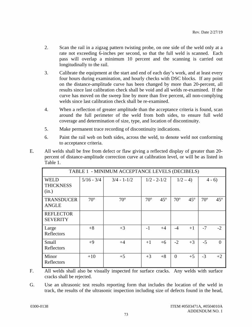
Rev. Date 2/27/19
0300-0138 ITEM #0503471A, #0504010A ADDENDUM NO. 1
2. Scan the rail in a zigzag pattern twisting probe, on one side of the weld only at a rate not exceeding 6-inches per second, so that the full weld is scanned. Each pass will overlap a minimum 10 percent and the scanning is carried out longitudinally to the rail.
3. Calibrate the equipment at the start and end of each day’s work, and at least every four hours during examination, and hourly checks with DSC blocks. If any point on the distance-amplitude curve has been changed by more than 20-percent, all results since last calibration check shall be void and all welds re-examined. If the curve has moved on the sweep line by more than five percent, all non-complying welds since last calibration check shall be re-examined.
4. When a reflection of greater amplitude than the acceptance criteria is found, scan around the full perimeter of the weld from both sides, to ensure full weld coverage and determination of size, type, and location of discontinuity.
5. Make permanent trace recording of discontinuity indications.
6. Paint the rail web on both sides, across the weld, to denote weld not conforming to acceptance criteria.
E. All welds shall be free from defect or flaw giving a reflected display of greater than 20-percent of distance-amplitude correction curve at calibration level, or will be as listed in Table 1.
TABLE 1 - MINIMUM ACCEPTANCE LEVELS (DECIBELS)
WELD THICKNESS (in.)
5/16 - 3/4 3/4 - 1-1/2 1/2 - 2-1/2 1/2 – 4) 4 - 6)
TRANSDUCER ANGLE
70o 70o 70o 45o 70o 45o 70o 45o
REFLECTOR SEVERITY
Large Reflectors
+8 +3 -1 +4 -4 +1 -7 -2
Small Reflectors
+9 +4 +1 +6 -2 +3 -5 0
Minor Reflectors
+10 +5 +3 +8 0 +5 -3 +2
F. All welds shall also be visually inspected for surface cracks. Any welds with surface cracks shall be rejected.
G. Use an ultrasonic test results reporting form that includes the location of the weld in track, the results of the ultrasonic inspection including size of defects found in the head,
73
Rev. Date 2/27/19
0300-0138 ITEM #0503471A, #0504010A ADDENDUM NO. 1
web or base of rail, shape identity and location of all reflections, trace record, the results of the visual inspection, name of inspector, and other information as needed.
Method of Measurement: Turnouts will be measured for payment by the count of turnouts furnished and installed. One turnout includes switch ties, head block timbers, frog, switch points and stock rails, closure rails, and all throw rods. Each turnout unit shall be considered as beginning at the Number Zero tie ahead of the point of switch and extending to the Last Long Timber beyond the frog. Other track outside of that zone will be measured by the linear foot as indicated above. Railroad Track Work will be measured for payment by the actual number of lineal feet measured along the centerline of track, installed and accepted excluding the length of turnouts. Track consists of two rails, connecting ties, bumping posts and all appurtenances. Where rail ends are staggered, the average of the two rail ends shall be used as the point of measurement. The allotment of 400 ties to be furnished and installed as directed by the Engineer concurrent with track installation shall not be measured for payment, but shall be considered as incidental to the Railroad Track Work item. Basis of Payment: This work will be paid for at the contract unit price per “Each” for Turnout Installation which price shall include furnishing and installing turnouts complete in place including all materials, equipment, tools, and labor incidental thereto and “Linear Feet” for Railroad Track Work, complete in place, which price shall include all material, equipment, tools, welding, testing, and labor incidental thereto. The cost for excavation below the finished grade of the track, backfilling, subballast, ballast and disposal of surplus material will not be paid under this section, but will be paid for under their respective contract items. Pay Item Pay Unit Turnout Installation EA.
Railroad Track Work L.F
74
TECHNICAL
SPECIFICATION
CODE: SPC-CBST-08
PAGE 1 of 21
REV. DATE: 02/02/2016 V1.0
TECHNICAL SPECIFICATION
TREATED CROSSTIES, BRACKET TIES,
SWITCH TIES AND TIE BLOCKS
REVISION HISTORY
REV. DESCRIPTION OF CHANGE AUTHOR EFFECTIVE DATE
0 First Issue 03/01/1984
1 11/25/1985
2 10/08/1986
3 02/11/1993
4 12/23/1997
5 06/12/2000
6 12/21/2010
7 New format 06/05/2015
8 Added specs from AREMA
and AWPA
2/2/2016
0300-0138 ITEM #0503471A, #0504010AADDENDUM NO. 1
75
BurkeMJ
Line
TECHNICAL
SPECIFICATION
CODE: SPC-CBST-08
PAGE 2 of 21
REV. DATE: 02/02/2016 V1.0
Disclaimer
This document was prepared for use on Metro North Railroad (MNR) network only.
MNR makes no warranties, express or implied, that compliance with the contents of this document shall be sufficient to ensure safe
systems or work or operation. It is the document user’s sole responsibility to ensure that the copy of the document it is viewing is
the current version of the document as in use by MNR.
MNR accepts no liability whatsoever in relation to the use of this document by any party, and MNR excludes any liability which
arises in any matter by the use of this document.
Copyright
The information in this document is owned by MNR and no part of this document may be reproduced, altered, stored or transmitted
by any person without the prior consent of MNR.
0300-0138 ITEM #0503471A, #0504010AADDENDUM NO. 1
76
BurkeMJ
Line
TECHNICAL
SPECIFICATION
CODE: SPC-CBST-08
PAGE 3 of 21
REV. DATE: 02/02/2016 V1.0
Contents
PART 1 – GENERAL ................................................................................................................................................... 4 1.1 INTRODUCTION ............................................................................................................................................ 4 1.2 STANDARDS .................................................................................................................................................. 4 PART 2 – MATERIALS ............................................................................................................................................... 5 2.1 TYPE OF WOOD............................................................................................................................................. 5 PART 3 – REQUIREMENTS ....................................................................................................................................... 6 3.1 GENERAL REQUIREMENTS ........................................................................................................................ 6 3.2 DIMENSIONAL REQUIREMENTS ............................................................................................................... 7 3.3 PHYSICAL REQUIREMENTS ..................................................................................................................... 10 3.4 MECHANICAL REQUIREMENTS .............................................................................................................. 12 3.5 CONDITIONING PRIOR TO TREATMENT ............................................................................................... 13 3.6 MARKING ..................................................................................................................................................... 14 PART 4 – PROCESSING ............................................................................................................................................ 15 4.1 INCISING ...................................................................................................................................................... 15 4.2 TIMBER IDENTIFICATION ........................................................................................................................ 15 4.3 AIR SEASONING.......................................................................................................................................... 15 4.4 ANTI-SPLITTING DEVICES ....................................................................................................................... 16 4.5 PRESERVATIVE TREATMENT.................................................................................................................. 16 PART 5 – QUALITY ASSURANCE .......................................................................................................................... 18 5.1 ACTION SUBMITTAL ................................................................................................................................. 18 5.2 INSPECTION ................................................................................................................................................. 18 5.3 TESTING ....................................................................................................................................................... 19 PART 6 – SHIPMENT AND ACCEPTANCE ........................................................................................................... 20 6.1 SHIPMENT .................................................................................................................................................... 20 6.2 ACCEPTANCE .............................................................................................................................................. 21
0300-0138 ITEM #0503471A, #0504010AADDENDUM NO. 1
77
BurkeMJ
Line
TECHNICAL
SPECIFICATION
CODE: SPC-CBST-08
PAGE 4 of 21
REV. DATE: 02/02/2016 V1.0
PART 1 – GENERAL
1.1 INTRODUCTION
This document includes specifications for manufacturing and delivery of crossties, bracket ties, switch
ties and tie blocks for use in rail transit track throughout the entire Metro-North Railroad (MNR) territory
in New York and Connecticut, including Grand Central Terminal.
1.2 STANDARDS
The following referenced documents are indispensable for the application of this document. For dated
references, only the edition cited applies. For undated references, the latest edition of the referenced
document (including any amendments) applies.
A. ASTM: American Society for Testing and Material.
ASTM E84: Flame Spread and Smoke Developed Fire Testing.
ASTM E119: Standard Test Methods for Fire Tests of Building Construction and Materials.
ASTM A240: Standard Specification for Chromium and Chromium-Nickel Stainless Steel Plate,
Sheet, and Strip for Pressure Vessels and for General Applications.
ASTM A653: Standard Specification for Steel Sheet, Zinc-Coated (Galvanized) or Zinc-Iron
Alloy-Coated (Galvannealed) by the Hot-Dip Process.
B. AWPA: American Wood Protection Association
AWPA M2: Standard for Inspection of Wood Products Treated with Preservatives.
AWPA M3: Standard Quality Control Procedures for Wood Preserving Plants.
AWPA P2: Standard for Creosote Solutions.
AWPA U1: Use Category System: User Specification for Treated Wood.
AWPA T1: Use Category System: Processing and Treatment Standard.
C. AREMA: American Railroad Engineering and Maintenance of Way Association Manual for
Railroad Engineering (Latest Edition.)
D. RTA: Railway Tie Association – Specifications Timber Crossties and Switch Ties.
E. WCLIB: West Coast Lumber Inspection Bureau.
F. AREA Manual for Railway Engineering.
G. ISO 9001:2008 or Association of American Railroads AAR-M1003 Section J for Quality Assurance.
H. NFPA: National Fire Protection Association.
NFPA 130, Standard for Fixed Guideway and Passenger Rail Systems.
0300-0138 ITEM #0503471A, #0504010AADDENDUM NO. 1
78
BurkeMJ
Line
TECHNICAL
SPECIFICATION
CODE: SPC-CBST-08
PAGE 5 of 21
REV. DATE: 02/02/2016 V1.0
PART 2 – MATERIALS
2.1 TYPE OF WOOD
2.1.1 GENERAL
A. Unless otherwise indicated, crossties, bracket ties, switch ties and tie blocks shall conform to all
relevant requirements of current AREMA practice and recognized standards existing in countries
where the timber is harvested and/or where the products are produced.
2.1.2 ACCEPTABLE SPECIES
A. The following woods shall be acceptable species for the manufacture of crossties, tie blocks,
switch ties and bracket ties:
Group A: Black Locust, Black Walnut , Honey Locust , Red Oak and White Oak.
Group B: Beech, Birches, Catalpa, Cherries, Elms, Hackberry, Hard Maples, Mulberries,
Sassafras, Soft Maples, Sycamore and White Walnut.
B. No Water Oak or Ash will be accepted.
C. Unless otherwise specified, a minimum of 85 percent of any order shall be filled from the Group
A materials, and a maximum of 15 percent from Group B materials.
0300-0138 ITEM #0503471A, #0504010AADDENDUM NO. 1
79
BurkeMJ
Line

TECHNICAL
SPECIFICATION
CODE: SPC-CBST-08
PAGE 6 of 21
REV. DATE: 02/02/2016 V1.0
PART 3 – REQUIREMENTS
3.1 GENERAL REQUIREMENTS
3.1.1 DEFINITIONS
Definitions for switch ties and crossties shall be in accordance with the current Chapter 30 of the
AREMA Manual for Railway Engineering, except as otherwise indicated below:
A. A crosstie, a switch tie or a bracket tie is any tie of nominal maximum length greater than 52
inches.
B. A tie block is any tie of nominal maximum length less than or equal to 52 inches.
C. A bark seam is a pocket or patch of bark partially or wholly enclosed in the wood.
D. Slanting grain is a deviation of the fiber from a line parallel to the sides of the piece.
E. A large knot is a knot greater than ¼ of the width of the surface on which it appears.
F. Numerous knots shall be any number of knots equaling a large knot in damaging effect.
G. A large hole is either:
1. A cavity within the rail bearing area of the tie or tie block which is more than ½ inch in
diameter and more than 1 ½ inches deep, or a hole of any diameter less than ½ inch but up
to 3 inches deep, the section of the tie between twenty inches (20”) and forty inches (40”)
from its middle.
2. A cavity outside the rail bearing area the tie or tie block which is greater in diameter than ¼
the width of the surface on which it appears and more than 1 ½ inches deep.
H. Numerous holes shall be any number of holes equaling a large hole in damaging effect. Such
holes may be caused in manufacture or otherwise.
I. End check is a separation of the wood along any end surface of a crosstie or tie block.
J. A check is a separation of the wood along only one face of the crosstie or tie block. Do not
count the end as a surface.
K. A ring shake is a separation along the grain between annual growth rings.
L. An edge is the intersection of two surfaces.
0300-0138 ITEM #0503471A, #0504010AADDENDUM NO. 1
80
BurkeMJ
Line
TECHNICAL
SPECIFICATION
CODE: SPC-CBST-08
PAGE 7 of 21
REV. DATE: 02/02/2016 V1.0
M. A split is a separation of the wood extending from one surface, through the piece, to an
opposite surface or to an adjacent surface.
N. Ends are considered to be both a surface and a face.
O. Twist means that any point of a face is not on the plane defined by three of the adjacent corners
of that face.
P. Bow means that the piece is bent either in its horizontal or vertical plane, but its ends are
parallel to each other and without relative rotation with respect to each other.
Q. A corner is the intersection of three edges.
R. Top is the horizontal face farthest from the heartwood or the narrowest horizontal face if the
heartwood is centered. Sides are the vertical faces immediately adjacent to the top face.
3.1.2 QUALITY
A. Except as hereinafter specified, all ties shall be free from any defects that may impair their
durability or strength, such as decay, splits, large checks, large shakes, slanting grain, large or
numerous holes or knots.
B. Except as hereinafter provided, all ties shall be straight, well sawed, cut square at the ends, have
bottom and top parallel, and have bark entirely removed.
C. As a general rule, wood defects within the two rail-bearing areas [the regions from eleven inches
(11”) to thirty-one inches (31”) from each end of an 8’-6” tie] can cause serious problems and
shall be avoided.
D. All crossties, bracket ties, switch ties and tie blocks shipped to MNR must be production (mill)
runs produced specifically for MNR. MNR must be given the opportunity for mill inspection as
specified hereinafter.
3.2 DIMENSIONAL REQUIREMENTS
3.2.1 DIMENSIONS
A. All timber ties shall be sawed on top, bottom and sides, and shall be sized according to drawings,
and switch timber shall be as specified. Dry or treated timber may be ¼ inch thinner or narrower
than the specified sizes. Ties exceeding these dimensions by more than 1 inch shall be rejected.
B. Crossties, bracket ties, switch ties and tie blocks: All rail-bearing areas shall have seven inches
(7”) grade crossties (except for tie blocks). The grade of each tie shall be determined at the point
of most wane on the top face of the tie within the rail-bearing areas. The rail-bearing areas are
those sections between 20” and 40” from the center of the tie. The top of the tie shall be
0300-0138 ITEM #0503471A, #0504010AADDENDUM NO. 1
81
BurkeMJ
Line
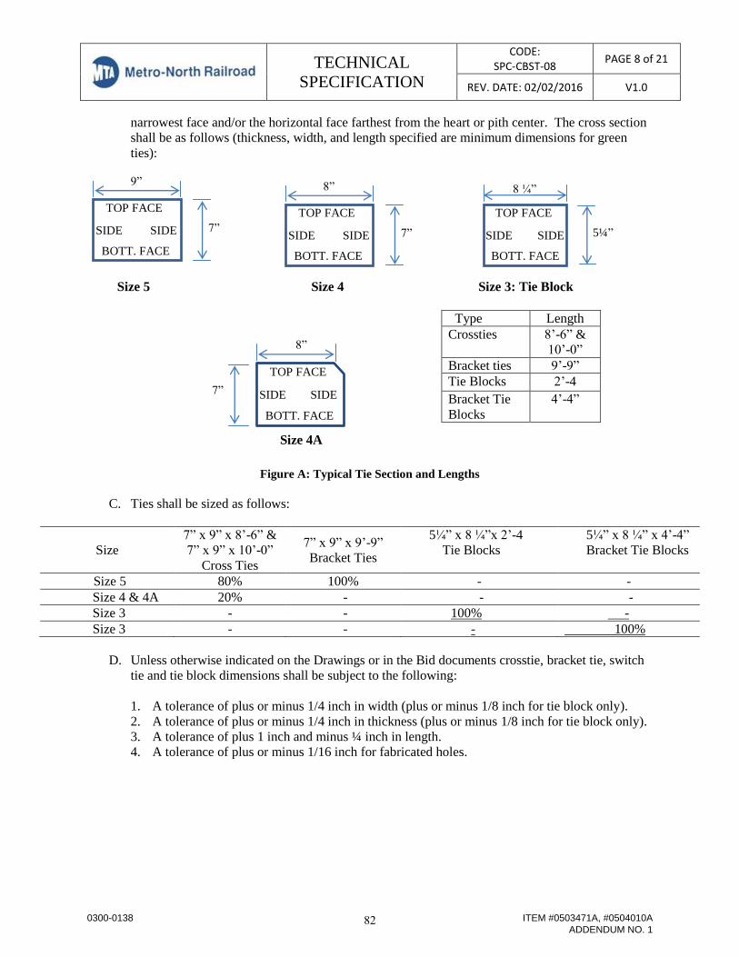
TECHNICAL
SPECIFICATION
CODE: SPC-CBST-08
PAGE 8 of 21
REV. DATE: 02/02/2016 V1.0
TOP FACE
SIDE SIDE
BOTT. FACE
7”
9”
TOP FACE
SIDE SIDE
BOTT. FACE
7”
8” 8 ¼”
5¼”
TOP FACE
SIDE SIDE
BOTT. FACE
TOP FACE
SIDE SIDE
BOTT. FACE
7”
8”
narrowest face and/or the horizontal face farthest from the heart or pith center. The cross section
shall be as follows (thickness, width, and length specified are minimum dimensions for green
ties):
Size 5 Size 4 Size 3: Tie Block
Size 4A
Figure A: Typical Tie Section and Lengths
C. Ties shall be sized as follows:
Size
7” x 9” x 8’-6” &
7” x 9” x 10’-0”
Cross Ties
7” x 9” x 9’-9”
Bracket Ties
5¼” x 8 ¼”x 2’-4
Tie Blocks
5¼” x 8 ¼” x 4’-4”
Bracket Tie Blocks
Size 5 80% 100% - -
Size 4 & 4A 20% - - -
Size 3 - - 100% -
Size 3 - - - 100%
D. Unless otherwise indicated on the Drawings or in the Bid documents crosstie, bracket tie, switch
tie and tie block dimensions shall be subject to the following:
1. A tolerance of plus or minus 1/4 inch in width (plus or minus 1/8 inch for tie block only).
2. A tolerance of plus or minus 1/4 inch in thickness (plus or minus 1/8 inch for tie block only).
3. A tolerance of plus 1 inch and minus ¼ inch in length.
4. A tolerance of plus or minus 1/16 inch for fabricated holes.
Type Length
Crossties 8’-6” &
10’-0”
Bracket ties 9’-9”
Tie Blocks 2’-4
Bracket Tie
Blocks
4’-4”
0300-0138 ITEM #0503471A, #0504010AADDENDUM NO. 1
82
BurkeMJ
Line
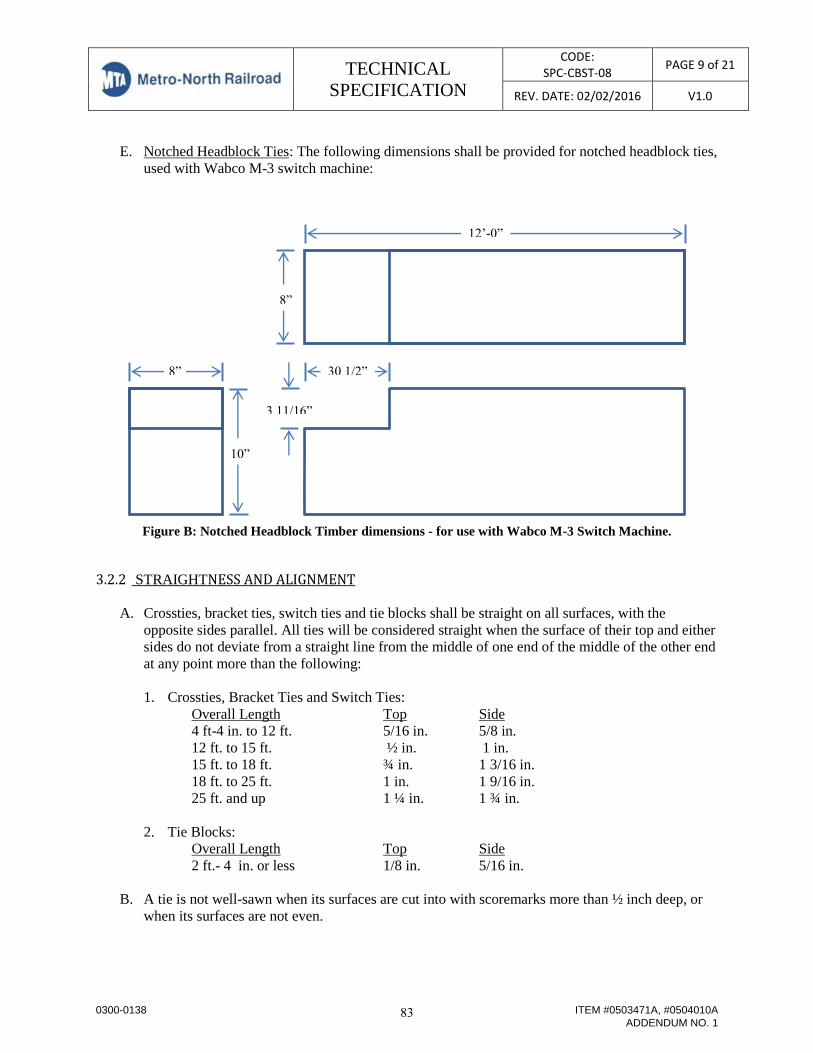
TECHNICAL
SPECIFICATION
CODE: SPC-CBST-08
PAGE 9 of 21
REV. DATE: 02/02/2016 V1.0
E. Notched Headblock Ties: The following dimensions shall be provided for notched headblock ties,
used with Wabco M-3 switch machine:
Figure B: Notched Headblock Timber dimensions - for use with Wabco M-3 Switch Machine.
3.2.2 STRAIGHTNESS AND ALIGNMENT
A. Crossties, bracket ties, switch ties and tie blocks shall be straight on all surfaces, with the
opposite sides parallel. All ties will be considered straight when the surface of their top and either
sides do not deviate from a straight line from the middle of one end of the middle of the other end
at any point more than the following:
1. Crossties, Bracket Ties and Switch Ties:
Overall Length Top Side
4 ft-4 in. to 12 ft. 5/16 in. 5/8 in.
12 ft. to 15 ft. ½ in. 1 in.
15 ft. to 18 ft. ¾ in. 1 3/16 in.
18 ft. to 25 ft. 1 in. 1 9/16 in.
25 ft. and up 1 ¼ in. 1 ¾ in.
2. Tie Blocks:
Overall Length Top Side
2 ft.- 4 in. or less 1/8 in. 5/16 in.
B. A tie is not well-sawn when its surfaces are cut into with scoremarks more than ½ inch deep, or
when its surfaces are not even.
8”
10”
12’-0”
8”
30 1/2”
3 11/16”
0300-0138 ITEM #0503471A, #0504010AADDENDUM NO. 1
83
BurkeMJ
Line
TECHNICAL
SPECIFICATION
CODE: SPC-CBST-08
PAGE 10 of 21
REV. DATE: 02/02/2016 V1.0
C. For proper seating of nail plates, tie ends must be flat, and will be considered square with a sloped
end of up to 1/2 inch, which equals a 1 in 20 cant.
3.3 PHYSICAL REQUIREMENTS
3.3.1 DECAY AND PITH
A. All ties having decay and/or pith will be rejected. Brown-to-red and white-to-yellow mold stains
are not allowed. “Blue Stain” is not decay and is permissible in any wood.
B. Soft, discolored areas are typically an indication of the presence of decay fungi will be rejected.
3.3.2 HOLES
A. All ties with large holes cannot support the stresses placed on the track, therefore they cannot be
placed into service.
B. A large hole is defined as per Section 3.1.1 above.
3.3.3 KNOTS
A. A large knot is one whose average diameter exceeds one-third (1/3) the width of the surface on
which it appears; but such a knot may be allowed if it occurs outside the bearing areas. Numerous
knots are any number equaling one-half of a large knot in damage effect.
3.3.4 BARK SEAMS
A. Bark Seam will be allowed provided they are not more than two inches (2”) below surface, one-
quarter inch (1/4”) wide and /or ten inches (10”) long.
3.3.5 SLOPE GRAIN (CROSSGRAIN)
A. Except in woods with interlocking grain, crossties shall not exceed slope of grain in excess of 1 in
15.
3.3.6 WANE
A. Wane is defined as bark or the lack of wood. Timber wane shall not exceed one inch (1”) wide on
the surface on which appears and/or over one-sixth (1/6) the length of the timber. See section
3.2.1.B for rail-bearing area.
0300-0138 ITEM #0503471A, #0504010AADDENDUM NO. 1
84
BurkeMJ
Line
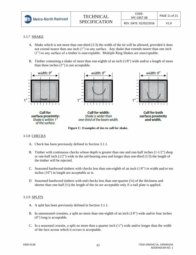
TECHNICAL
SPECIFICATION
CODE: SPC-CBST-08
PAGE 11 of 21
REV. DATE: 02/02/2016 V1.0
3.3.7 SHAKE
A. Shake which is not more than one-third (1/3) the width of the tie will be allowed, provided it does
not extend nearer than one inch (1”) to any surface. Any shake that extends nearer than one inch
(1”) to any surface of a timber is unacceptable. Multiple Ring Shakes are unacceptable.
B. Timber containing a shake of more than one-eighth of an inch (1/8") wide and/or a length of more
than three inches (3”) is not acceptable.
Figure C: Examples of ties to cull for shake.
3.3.8 CHECKS
A. Check has been previously defined in Section 3.1.1.
B. Timber with continuous checks whose depth is greater than one and one-half inches (1-1/2”) deep
or one-half inch (1/2”) wide in the rail-bearing area and longer than one-third (1/3) the length of
the timber will be rejected.
C. Seasoned hardwood timbers with checks less than one-eighth of an inch (1/8”) in width and/or ten
inches (10”) in length are acceptable as is.
D. Seasoned hardwood timbers with end checks less than one-quarter (¼) of the thickness and
shorter than one-half (½) the length of the tie are acceptable only if a nail plate is applied.
3.3.9 SPLITS
A. A split has been previously defined in Section 3.1.1.
B. In unseasoned crossties, a split no more than one-eighth of an inch (1⁄8”) wide and/or four inches
(4”) long is acceptable.
C. In a seasoned crosstie, a split no more than a quarter inch (¼”) wide and/or longer than the width
of the face across which it occurs is acceptable.
0300-0138 ITEM #0503471A, #0504010AADDENDUM NO. 1
85
BurkeMJ
Line

TECHNICAL
SPECIFICATION
CODE: SPC-CBST-08
PAGE 12 of 21
REV. DATE: 02/02/2016 V1.0
D. In seasoned cross-ties, a split exceeding the limit is acceptable, provided split limitations and anti-
splitting devices are approved by “MNR”.
E. End splits and shrinkage cracks that do not impair the ability of the wood to hold a fastening or
that does not affect the strength of the material will be permitted.
3.3.10 TWIST
A. Any twist in a timber shall not exceed One-eight inch (1/8 ”) in any Eight feet (8’) length.
3.3.11 MANUFACTURING
A. Any timber containing a manufacturing defect will be evaluated by the inspector and judged
accordingly.
B. Ties need to be bark-free, free of warp, and cut squarely. For proper seating of nail plates, tie ends
must be flat, and will be considered square with a sloped end of up to half inch (1/2”).
3.4 MECHANICAL REQUIREMENTS
A. These properties are represented as the average mechanical properties of the oak wood species,
most commonly measured and represented as “strength properties” for design, as shown in the
following table, for use in crossties, bracket ties, switch ties and tie blocks:
Table 1. Strength Properties for some commercial wood used for MNR Crossties, Bracket Ties, Switch Ties
and Tie Blocks
Static Bending
Common and botanical
names of species
Moisture
Content
Modulus of
Rupture
(psi)
Modulus of
Elasticity
(x106 psi)
Compression
parallel to
grain (psi)
Shear
parallel to
grain (psi)
Oak, Red
Black Green 8,200 1.18 3,470 1,220
12% 13,900 1.64 6,520 1,910
Cherrybark Green 10,800 1.79 4,620 1,320
12% 18,100 2.28 8,740 2,000
Laurel Green 7,900 1.39 3,170 1,180
12% 12,600 1.69 6,980 1,830
Northern Red Green 8,300 1.35 3,440 1,210
12% 14,300 1.82 6,760 1,780
Pin Green 8,300 1.32 3,680 1,290
12% 14,000 1.73 6,820 2,080
Scarlet Green 10,400 1.48 4,090 1,410
12% 17,400 1.91 8,330 1,890
0300-0138 ITEM #0503471A, #0504010AADDENDUM NO. 1
86
BurkeMJ
Line

TECHNICAL
SPECIFICATION
CODE: SPC-CBST-08
PAGE 13 of 21
REV. DATE: 02/02/2016 V1.0
Southern Red Green 6,900 1.14 3,030 930
12% 10,900 1.49 6,090 1,390
Willow Green 7,400 1.29 3,000 1,180
12% 14,500 1.90 7,040 1,650
Oak, White
Bur Green 7,200 0.88 3,290 1,350
12% 10,300 1.03 6,060 1,820
Chesnut Green 8,000 1.37 3,520 1,210
12% 13,300 1.59 6,830 1,490
Live Green 11,900 1.58 5,430 2,210
12% 18,400 1.98 8,900 2,660
Overcup Green 8,000 1.15 3,370 1,320
12% 12,600 1.42 6,200 2,000
Post Green 8,100 1.09 3,480 1,280
12% 13,200 1.51 6,600 1,840
Swamp chesnut Green 8,500 1.35 3,540 1,260
12% 13,99 1.77 7,270 1,990
Swamp white Green 9,900 1.59 4,360 1,300
12% 17,700 2.05 8,600 2,000
Source: General Technical Report FPL–GTR–190
3.5 CONDITIONING PRIOR TO TREATMENT
A. Timber Crossties shall be shall be seasoned in accordance with the current American Wood
Preservers Association (AWPA) Standard C6, Crossties and Switch Ties-Preservative Treatment
by Pressure Processes, except as follows:
1. Timber crossties shall be conditioned by either air seasoning, steam conditioning, vapor
drying, Boulton process or kiln drying, except that the duration of air seasoning shall be that
which results in a final moisture content of the wood below 50% prior to treatment for oaks
or 45% for mixed hardwoods (moisture levels shall be determined by a moisture meter.
2. Timber crossties shall be dressed on the top and bottom surfaces to the required dimensions
prior to treatment.
3. After seasoning, the top and bottom surfaces of tie blocks, crossties and timbers shall be
finished to the required dimensions. “To finish to the required dimensions” means to produce
flat and even surfaces of the specified dimensional tolerances, and free of any defects
produced by the handling of the piece by a mechanical device such as excess score marks,
rough surface cuts, indentations or steps, grooves, etc.
0300-0138 ITEM #0503471A, #0504010AADDENDUM NO. 1
87
BurkeMJ
Line
TECHNICAL
SPECIFICATION
CODE: SPC-CBST-08
PAGE 14 of 21
REV. DATE: 02/02/2016 V1.0
3.6 MARKING
A. Switch ties, crossties, bracket ties and tie blocks shall be marked after seasoning in accordance
with the AREMA Manual, Chapter 30, Specifications for Timber Crossties, Marking Ties to
Indicate Size Acceptance, except as specified below:
1. Marking shall indicate the manufacturer’s name or trademark, the month and year of
production and the manufacturer’s plant identification in figures at least ½ inch high. If dating
nails are used, only the last two digits of the year of manufacture shall be shown.
2. Marking shall be by dating nails, hot-iron branding or tagging. When anti-splitting devices are
applied, brands or tags shall appear. Tags, if used, shall be of stainless steel conforming to ASTM
Designation A240. Dating nails shall conform to the requirements of the AREA Manual for
Railway Engineering chapter 3 Ties and Wood Preservation, section 1.8, Specifications for
Dating Nails, dated 1975 or later.
B. Each bundle of switch ties, crossties, bracket ties and tie blocks accepted by MNR shall be
branded by MNR’s inspector by hammering a distinctive mark approved by MNR for this
purpose. The exposed face of each tie or tie block in each bundle and the end of each tie or tie
block in the bundle shall be clearly marked.
0300-0138 ITEM #0503471A, #0504010AADDENDUM NO. 1
88
BurkeMJ
Line
TECHNICAL
SPECIFICATION
CODE: SPC-CBST-08
PAGE 15 of 21
REV. DATE: 02/02/2016 V1.0
PART 4 – PROCESSING
4.1 INCISING
A. All timbers shall be incised on four sides in accordance with AREMA incising pattern as
described in Part 3 Section 3.6. The incisions prior to surfacing shall be three-quarters inch (¾”)
deep with teeth not more than seven-thirty seconds inch (7/32”) thick.
B. This pattern produces a nominal 17 incisions in any Six inch by Six inch (6”x6”) area and each
timber shall have a minimum of 14 incisions in any Six inch by Six inch (6”x6”) area of the sides.
4.2 TIMBER IDENTIFICATION
A. Timber for the Railroad shall be identified by a distinctive “MNR” marking on one end of the
timber, in accordance with metal plate identification shown on the plans.
B. Marking shall be so placed that it may be read correctly, with the wider heart- wood of the timber
faced downward.
C. “MNR” brand Marking Iron shall be supplied by Vendor, subject to Railroad approval, or in
accordance to plans.
D. Timber shall be marked to indicate manufacturer, year, , Bridge number, and tie number.
Markings shall be subject to approval by the Railroad.
4.3 AIR SEASONING
A. Timbers shall be conditioned prior to treatment by a procedure which will render it receptive to
penetration by preservative without reducing its strength
B. Moisture determination shall be made on a representative sample of each lot ready for seasoned
inspection. Moisture determination and allowable moisture contents shall be in accordance with
the American Railway Engineering and Maintenance-of-Way Association Manual for Railway
Engineering (AREMA) part 3 section 3.6.3 and the American Wood Protection Association
(AWPA) standard M2, section 2.
C. All stacks of seasoning timbers shall be supported on treated or non-decaying sills, and the first
layer shall be off the ground 12” or more. Space between rows of stacks shall not be less than 3
feet.
D. Crossing timbers shall be stacked using the “German” ricking method.
0300-0138 ITEM #0503471A, #0504010AADDENDUM NO. 1
89
BurkeMJ
Line
TECHNICAL
SPECIFICATION
CODE: SPC-CBST-08
PAGE 16 of 21
REV. DATE: 02/02/2016 V1.0
E. “Boulton Conditioning” may be used when time constraints make air seasoning impractical with
the prior approval of the railway
4.4 ANTI-SPLITTING DEVICES
A. All timber ties shall have an anti-splitting device on each ends. Splits longer than four inches (4”)
can be gang plated before treatment. After application, the nail plate must be flush with the tie
ends and there must be no observed separation along the plane on split line.
B. The nail plates shall be sufficiently sized to fully cover the split. The plates shall be at least 18
gauge-galvanized steel with four to five 9/16” teeth per square inch. The steel sheet shall meet
ASTM A653 structural steel (SS) grade 40 or better with a minimum coating designation G60
(0.60 oz./ft2).
4.5 PRESERVATIVE TREATMENT
A. All ties shall be preservative treated with any of the following preservatives. Any other
preservative treatment shall be submitted to MNR for review and approval.
1. Coal tar creosote in accordance with the current AWPA Standard P1, Standard for Coal Tar
Creosote for Land and Fresh Water Use.
2. Creosote coal tar solution in accordance with the current AWPA Standard P2, Standard for
Creosote and Creosote Solutions, Grade A.
3. Creosote petroleum solution in accordance with the current AWPA Standard C6.
4. Copper Naphthenate solution, as follows:
4.1. Preservative treatment of crossties and timbers shall be by the pressure process and in
accordance with the latest AWPA Standards and AASHTO Designation M133.
4.2. Crossties and timbers to be treated with Copper Naphthenate shall be in accordance with
AWPA P9 Type A Hydrocarbon Solvent.
B. Treatment shall be in accordance with AWPA U1 of the American Wood Preservers Association
by the Empty Cell Process with Initial Air.
C. Retention shall be seven (7) lbs. of solution per cubic foot of wood determined as specified in the
AWPA Standards.
D. All retentions shall be calculated by cubic foot volumes for ties supplied to the Railroad.
E. Complete plant treating reports shall be submitted with each shipment in accordance with
AREMA, Wood Preservative, "Records of Treatment and Reports of Inspection”.
0300-0138 ITEM #0503471A, #0504010AADDENDUM NO. 1
90
BurkeMJ
Line
TECHNICAL
SPECIFICATION
CODE: SPC-CBST-08
PAGE 17 of 21
REV. DATE: 02/02/2016 V1.0
F. AREMA Part 3 section 3.6.3 a through 3.6.3d shall be considered as guideline in determining
whether wood is dry enough to treat. The railway however ultimately reserves the right to specify
acceptable moisture content for any hardwood or softwood specie before treatment.
F. Timbers shall be treated in accordance with the latest edition of American Railway Engineering
and Maintenance of Way (AREMA), Part 3, Section 3.6 “Wood Preserving”, However, ties
designated as “High Density” timbers, those ties destined for installation site within the
“Deterioration Zone” as identified as Zones 3, 4, and 5 in AWPA U1, shall receive the following
treatment in lieu of that outlined in AREMA:
Red Oak 7.0 lb. /cu ft. Preservative Solution P2
Gum & Hard Maple 7.0 lb./cu ft. Preservative Solution P2
Under no circumstances shall “High Density” timbers consist of White Oak.
0300-0138 ITEM #0503471A, #0504010AADDENDUM NO. 1
91
BurkeMJ
Line
TECHNICAL
SPECIFICATION
CODE: SPC-CBST-08
PAGE 18 of 21
REV. DATE: 02/02/2016 V1.0
PART 5 – QUALITY ASSURANCE
5.1 ACTION SUBMITTAL
C. The supplier shall submit the following information;
1. Procedure for inspection of treated crossties.
2. Compliance: Supplier or manufacture’s certification that the materials delivered to the site are
in compliance with this specification.
3. Test: Certified test results, as required to demonstrate compliance.
5.2 INSPECTION
A. Inspection shall be performed by vendor to the standards described herein and as per AWPA M2
“Inspection of treated timber products”. An inspection procedure shall be submitted to the
Railroad for approval. Vendor shall send one copy of the daily inspection report for the
Railroad’s Director of Contract Administration and Procurement and one copy to a designated
representative of the Railroad for each day’s production. The Railroad reserves the right to
inspect timber both before and after treating and at any time during the treating process.
B. Inspectors shall make a reasonably close examination of the top, bottom, sides and ends of each
timber. Each timer shall be judged independently, without regard for the decisions on others in
the same lot. Rafted or boomed timbers too muddied for ready examination shall be rejected.
Timbers handled by hoists shall be turned over as inspected, at the expense of the vendor.
C. The treating plant shall provide, free of charge, suitable facilities and any equipment and
assistance necessary for the Railroad’s inspector to work efficiency.
D. MNR shall have the right at any time to test the preservative to be used in treating its ties.
Samples may be taken from any container in which the preservative is stored or used. As shall be
examined in accordance with American Wood Preservers’ Association Standard M2, latest
revision.
E. MNR’s representative shall have the right to examine any of the equipment used on any process
or method of treatment at any stage in the treatment
F. Timber ties and all materials and processes, shall be subject to inspection prior to shipment to
MNR’s facilities. The vendor (contractor) shall afford MNR’s inspector, at no additional cost to
MNR, all necessary facilities, equipment and labor at the manufacturer’s plant to enable MNR’s
inspector to perform proper inspections, as deemed necessary by MNR, during normal working
hours.
0300-0138 ITEM #0503471A, #0504010AADDENDUM NO. 1
92
BurkeMJ
Line
TECHNICAL
SPECIFICATION
CODE: SPC-CBST-08
PAGE 19 of 21
REV. DATE: 02/02/2016 V1.0
G. MNR inspector will make reasonably close inspection of the top, bottom, sides and ends of each
switch ties, crossties, bracket ties and tie blocks subsequent to seasoning. Each tie or tie block
shall be judged independently without regard for decisions on other ties or tie blocks in the same
lot.
H. MNR’s inspector will inspect the processes relative to seasoning switch ties, crossties, bracket
ties and tie blocks in accordance with these specifications.
I. Inspection of switch ties, crossties, bracket ties and tie blocks regarding their conformance with
the moisture content requirements shown in paragraph 3.5.B.1.shall be performed using a
Brookhuis FMD Moisture Meter, or functional equivalent (if an equivalent moisture meter is
used, it must have any of the wood species listed in paragraph 2.1.2 pre-programmed as one of
the choices). Moisture content shall be determined at a depth of not less than one inch from the
top or bottom surface at the approximate mid-point of the length of the tie block, tie or timber.
J. MNR reserves the right to make any additional inspections of all ties prior to seasoning and
subsequent to seasoning, during fabrication and after delivery to determine conformity to these
specifications. However, the plant inspection will be considered final with respect to the
preservative treatment materials and processes.
5.3 TESTING
A. The vendor (contractor) shall, at no additional cost to MNR, have performed all tests necessary to
assure that all switch ties, crossties, bracket ties and tie blocks are in accordance with these
specifications.
B. If the results of any test indicate that any switch ties, crossties or tie blocks do not conform to
these specifications, an additional test shall be made on a further group of switch tie, crosstie,
bracket tie and tie block specimens from the same lot. If the results of the additional tests indicate
that any switch ties, crossties, bracket ties or tie blocks do not conform to these specifications,
then the entire lot may be rejected.
0300-0138 ITEM #0503471A, #0504010AADDENDUM NO. 1
93
BurkeMJ
Line
TECHNICAL
SPECIFICATION
CODE: SPC-CBST-08
PAGE 20 of 21
REV. DATE: 02/02/2016 V1.0
PART 6 – SHIPMENT AND ACCEPTANCE
6.1 SHIPMENT
6.1.1 GENERAL
A. All ties shall be shipped to the locations indicated in the Bid Documents.
B. When specified, timber ties shall be identified for installation purposes with numerals not less
than half inch (1/2”) in height, stamped on metal tags and affixed to the tie on the mark end as
shown in the contract plans.
C. Switch ties, crossties, bracket ties and tie blocks shall be banded in bundles of the same size and
type. Unless otherwise indicated, the ties and timber shall be packaged as follows:
1. Ties and tie blocks less than 10 feet in length shall be banded in bundles of 20, except for
bracket ties as noted below.
2. Bracket ties (9’-9” in length) shall be banded in bundles of 15.
3. Ties equal or greater than 11 feet but less than 18 feet in length shall be banded in bundles of
15.
4. Ties equal to or greater than 18 feet in overall length shall be banded in bundles of 10.
D. Switch tie bundles shall be identified with, the name of the vendor, the description and the
quantity of ties or timber contained therein. Bundle all timber ties with number tags facing in the
same direction.
E. Switch ties bundles shall be banded with at least two (2) metallic straps. The banded bundles shall
be further banded together in units weighing less than 6,000 pounds each. Breathing strips can be
used in all bundles to allow air circulation
6.1.2 DELIVERY AND GENERAL PROVISIONS
A. Switch ties, crossties, bracket ties and tie blocks shall be delivered via flatbed trucks, or logging
trucks to the locations indicated in the Bid Documents.
B. MNR shall provide proper and adequate flagging protection to facilitate the delivery operations,
as is deemed necessary by the railroad.
C. On Railroad Premises: Timber shall be delivered and stacked as specified in the purchase
agreement. If they are to be inspected, they must be placed so all the timbers are accessible to the
inspector.
0300-0138 ITEM #0503471A, #0504010AADDENDUM NO. 1
94
BurkeMJ
Line
TECHNICAL
SPECIFICATION
CODE: SPC-CBST-08
PAGE 21 of 21
REV. DATE: 02/02/2016 V1.0
6.2 ACCEPTANCE
A. Ties that do not comply with this specification or which, notwithstanding tests, inspection or
acceptance at any previous time or location are found to contain deficiencies shall be subject to
rejection and returned to the supplier.
B. Final acceptance of switch ties, crossties, bracket ties and tie blocks will be subject to verification
of count and inspection after delivery to the locations indicated in the Bid Documents and receipt
of required shipping documents and inspection reports.
C. The supplier shall be entitled to a joint inspection of the defective timber ties at the railroad
premises.
D. The vendor (contractor) shall bear the cost of handling and transporting (in both directions)
rejected material, regardless of when or where the rejection was made within thirty (30) days after
the date of the inspection. All rejected material not removed by the end of this period will become
the property of the railroad.
0300-0138 ITEM #0503471A, #0504010AADDENDUM NO. 1
95
BurkeMJ
Line

Rev. Date 2/27/19
0300-0138 ITEM #0603169A ADDENDUM NO. 1
ITEM #0603169A - PROGRESS PHOTOGRAPHS
General:
Scope:
A. Under this item, the Contractor shall engage a qualified commercial photographer to take comprehensive construction documentation. The photographer shall be a firm or an individual of established reputation for not less than 5 years and as further defined within.
Comprehensive documentation includes:
1. Digital photographic documentation of the construction process progressively and at selected milestones.
2. Native mobile application and mobile website for Apple iOS and Android OS devices to
provide direct mobile access to online documentation and mobile application-supported software features.
3. Documentation inclusive of electronic indexing, navigation, cloud-based hosting, storage
and remote access, as applicable, throughout construction. B. Rights to all photographs and/or documents taken, paid for, and uploaded (submitted) by/to
the Department shall be the Departments property. Once uploaded, neither the Contractor nor Photographer may claim rights to the photo documentation.
Qualifications: A. The Contractor shall engage in services utilized within this specification with Multivista or
similar firm approved as equal to the qualifications below. 1. Demonstrable minimum experience of five (5) years in operation providing digital
photography construction documentation using advanced indexing/navigation systems.
2. Proficiency in the execution of digital photography including use and knowledge of associated equipment.
3. Representative portfolio of completed construction projects of similar type, size, duration and complexity as the Project.
4. At least three (3) references may be required.
B. The Contractor must have a local office and be able to respond to site visit requests with qualified personnel within twenty four (24) hours of notice.
96
Rev. Date 2/27/19
0300-0138 ITEM #0603169A ADDENDUM NO. 1
Documentation Platform and Delivery Method: A. Photographic Documentation:
1. Documentation indexing and navigation system will utilize actual construction drawings
(project plans) or equivalent as the basis for an interactive online interface.
2. For all photographic documentation referenced herein, indexing and navigation must be organized by both time (date-stamped) and location throughout the Project.
3. Documentation activity can be queried by date range via activity searches.
4. Documentation will combine indexing and navigation system with inspection-grade high-
resolution digital photography, designed to capture actual conditions throughout construction and at critical milestones.
5. Contractor documentation will be accessible online within 24 hours after each shoot
through the use of an Internet connection.
6. Documentation will allow for multiple-user access, simultaneously, online.
7. Access shall adhere to industry standards for information security and protection of data.
8. Multi-tiered access levels shall be achievable through use of individual accounts and passwords. Users of a sufficient tier will be able to identify other authorized users.
9. Online interface will allow users to upload digital photographic images to the
documentation indexing and navigation system.
a. Users will be able to link images to the project plans for customized location-based indexing.
b. The acting administrative user will be able to define permissions and access to uploaded
images. Access, per image, can be set to (1) the acting user only, (2) all project users or a (3) subset of project users.
10. Online interface will allow users to upload files to the documentation indexing and
navigation system. Supported file formats will include, at minimum, PDF, Microsoft Word documents, and Microsoft Excel spreadsheets, Microsoft PowerPoint presentations, JPEG, PNG. GIF, MPEG and Folders.
a. Users will be able to link files to the project floor for customized location-based
indexing.
97
Rev. Date 2/27/19
0300-0138 ITEM #0603169A ADDENDUM NO. 1
b. The acting administrative user will be able to define permissions and access to uploaded files. Access, per file, can be set to (1) the acting user only, (2) all project users or a (3) subset of project users.
11. Online interface will provide a repository where users can upload and store digital
photographic images and other files for the Project, separate from the construction drawings.
12. Online interface will allow users to create customizable tags that can be utilized with the
integrated reporting functionality to generate issue-specific image reports.
a. These reports must be made available through PDF export and a standalone link.
b. All image reports will identify the time, date and location of each image, and will include associated comments that can be archived indefinitely.
13. Online interface will allow users to mark-up images using integrated annotation
functionality.
14. Online interface will allow users to sort specific sets of images into custom albums.
a. Users will be able to select one or more images to create new custom albums.
b. Users will be able to add images to their existing custom albums.
c. Custom albums can contain a combination of user images who have access.
15. Online interface will support batch actions by allowing users to multi-select images and other files for viewing, exporting and saving.
a. When files are batch exported or saved, the quality of the images shall be of original
quality, but not to exceed 5MB in size per photo.
16. Online interface will allow users to tag images as “Favorites”. Users will be able to view all of their “Favorite” images from a centralized location.
B. Mobile App: All documentation that is accessible online through an Internet connection will
be accessible via a native mobile application (“mobile app”). The operation of supported features on the mobile app may vary from the online interface (standard/desktop web-browser interface) to accommodate the mobile application environment and improve the mobile experience. Mobile app will be supported for Apple iOS and Android OS devices, and will be available for download via the Apple App Store and Google Play Store.
1. Mobile app will utilize the same user credentials as the online access interface.
98

Rev. Date 2/27/19
0300-0138 ITEM #0603169A ADDENDUM NO. 1
2. Users will be able access photographic documentation by selecting photo sets (shoots and albums) or by navigating the project plans to the desired locations of photographs.
3. Mobile app will support date and location indexing for all photographic documentation.
Users will be able to switch between the two indexing options, either viewing all dated images associated with a single, selected location or viewing the entire project on a single, selected date.
4. Users will be able to upload their own photographic images.
a. If using a camera-enabled mobile device, users will be able to take a new photo to
upload from within the mobile app.
b. Users will be able to select from existing photos that are accessible from their mobile devices. Single and batch upload operations will be supported for existing photos.
c. Prior to uploading, the acting user will be able to do the following:
i. Select an existing custom album for the project to which the uploaded photo/batch
will be added.
ii. Add a comment to accompany the photo/batch.
iii. Specify a date on which the photo/batch was taken.
iv. Define permissions and access to the uploaded photo/batch. Access can be set to (1) the acting user only, (2) all project users or a (3) subset of project users.
5. Users will be able to view the following details for each image within the mobile app:
a. The date on which the photo was taken.
b. The title of the shoot for which the photo was taken (if captured as part of user
documentation).
c. The photo number corresponding to the project plan to which the photo is attached (if captured as part of user documentation).
d. The title of the album in which the photo is contained (if any).
6. Mobile app will support zoom functionality on photographic documentation. Zooming in
and out will be possible via double-tap and pinch-/stretch-to-zoom gestures.
C. Mobile Web-Browser Access to Documentation: All documentation that is accessible online through an Internet connection will be accessible via mobile devices, such as tablets and smart
99
Rev. Date 2/27/19
0300-0138 ITEM #0603169A ADDENDUM NO. 1
phones, in a format optimized for mobile-browser viewing and navigation. It is acknowledged that not all software features will be available in the mobile-browser version and functionality may vary from the “full site” version to optimize the mobile experience. Mobile access must be supported for at least the following mobile operating systems: Apple iOS, Android OS.
Contractor Support; Hosting; Client Access; Client Usage Rights; and Contractor Deliverables: A. The photographer contracted shall grant for any photographic documentation completed under
this construction contract to the publisher, the Department, and successors in interest, a non-exclusive, no fee copyright license to reproduce, publish, and display in any media.
B. Field personnel to undertake the documentation provided exclusively by the Contractor. Field personnel shall be OSHA certified and Metro-North Railroad Contractor Safety trained, if applicable, per the Project-specific safety programs. Coordination with project teams will be accomplished through a designated representative on-site at the Project, typically a Superintendent or Project Manager or their designee. Contractor’s operations team will provide regular updates regarding the status of the documentation, including completed elements of the documentation, the availability of recent documentation on-line and anticipated future shoot dates.
C. All on-line domain/web hosting, industry standard security measures and redundant server
back-up of the documentation are furnished by Contractor for the duration of the contract.
D. Contractor furnishes technical support related to using the system or service, including site visits when required and/or requested.
E. Upon completion of the Project, final copies of the documentation (the “Permanent Record”)
will be provided in a digital media format. On-line access terminates upon delivery of the Permanent Record or as agreed between Contractor and Client. Intellectual property rights associated with the digital media prepared in direct service of the Project shall transfer, along with the media itself, to the Client.
Construction Methods:
A. General: Take photographs with maximum depth of field and in focus.
a. Maintain internet based interactive key plan with each set of construction photographs that identifies each photographic location and orientation.
B. Preconstruction Photographs session: Before commencement of project work, take
photographs of Project site and surrounding properties, including existing items to remain during construction, from different vantage points, as directed by the Engineer.
a. Flag construction limits before taking construction photographs.
100

Rev. Date 2/27/19
0300-0138 ITEM #0603169A ADDENDUM NO. 1
b. Take photographs to show existing conditions before starting the work. The Engineer
will inform photographer of desired vantage points. c. Take photographs to show existing conditions adjacent to property before starting the
Work. d. Take photographs of existing buildings/structures either on or adjoining property to
accurately record physical conditions at start of construction. e. Take additional photographs as required to record settlement, cracking, or any other
deficiencies of adjacent structures, pavements, and improvements.
C. Periodic Construction Photographs sessions: Take photographs monthly coinciding as closely as possible with the completion of a major construction phase. In coordination with the Engineer, select vantage points to show status of construction and progress since last photographs were taken. Prior to taking any photographs review the proposed vantage points with the Engineer.
D. Final Completion Construction Photographs session: Take photographs after the date of
Substantial Completion for submission as Project Record Documents. The Engineer will inform photographer of desired vantage points.
E. Additional Photographic documentation and/or Video documentation: The Engineer may
request photographs in addition to periodic photographs specified. Additional documentation will be paid for by Change Order and are not included in the Contract Sum.
a. Three days' notice will be given, where feasible.
b. In emergency situations, take additional photographs within 24 hours of request. c. Circumstances that could require additional photographs include, but are not limited
to, the following: Special events / scheduled milestone events planned at Project site. d. Immediate follow-up when on-site events result in construction damage or losses. e. Photographs to be taken at fabrication locations away from Project site. These
photographs are not subject to unit prices or unit-cost allowances.
f. Substantial Completion of a major phase or component of the Work. g. Extra record photographs at time of final acceptance. h. Owner's request for special publicity photographs.
101

Rev. Date 2/27/19
0300-0138 ITEM #0603169A ADDENDUM NO. 1
Method of Measurement:
This work will be measured for payment by itemized photographic sessions outlined within as submitted to the Engineer. Photographic sessions are priced at a unit costs for each session regardless the final sum of photos taken and submitted.
Basis of Payment:
This work will be paid for at the Contract unit price each for "Progress Photographs" which price shall include all material, equipment, and labor incidental thereto. Where any submission's image files do not conform to the requirements herein, the Contractor shall not receive any payment for the item.
Pay item Pay Unit
Progress Photographs EA.
102
Rev. Date 2/27/19
0300-0138
ITEM #0971001A ADDENDUM NO. 1
ITEM #0971001A - MAINTENANCE AND PROTECTION OF TRAFFIC
Work shall conform to Section 9.71 of the Standard Specifications, supplemented as follows: Description: The Contractor shall maintain and protect traffic as noted in this Section. At no time, unless otherwise approved by the Engineer, shall the Contractor close or cause to be closed any portion of roadways beyond what is stipulated herein, or on the plans, as necessary to perform the work. The Contractor’s work operations shall be performed in the protected construction zones as shown on the Construction Traffic Control Plans and shall not encroach upon, nor be performed from the maintained vehicular travel paths. Work on adjacent projects may be going on at the same time as this project. Coordination between projects is mandatory so that proper traffic flow can be maintained at all times. The Contractor shall provide suitable lighted barriers or barricades erected and maintained at all times, around open trenches or excavations, or other work potentially dangerous to pedestrians and vehicular traffic. Payment shall be included in the lump sum price for Maintenance and Protection of Traffic Should the Contractor or the Contractor’s employees neglect to place and maintain barricades or lights, as required, the Engineer immediately, and without notice, may furnish, install and maintain barricades or lights. The cost thereof shall be borne by the Contractor and may be deducted from any amount due to become due to the Contractor under this Contract. The Contractor shall provide 4’ high temporary construction orange safety fence with 6’ – 2”x2” wooden stakes at 6’ spacing to secure the work areas as shown in the Staging Plans or as directed by the Engineer. If stakes cannot be installed in the ground, the Contractor shall use 5 Gallon buckets to encase the stakes with concrete for supporting the fence. Contractor is responsible to install, maintain, relocate, and remove the fence as required throughout the duration of the Project. Contractor may have to temporarily relocate the fence during storm events and during the winter season for snow removal or as directed by the Engineer. Any damaged fence shall be repaired by the Contractor at no additional cost. The Contractor shall ensure the fence does not encroach the right of way of active tracks throughout the Yard. The Contractor shall ensure a secure perimeter of the yard is maintained throughout the project duration.
103
Rev. Date 2/27/19
0300-0138
ITEM #0971001A ADDENDUM NO. 1
9.71.05—Basis of Payment: When the item of “Maintenance and Protection of Traffic” appears in the Contract, this work will be paid for at the Contract lump sum price for “Maintenance and Protection of Traffic.” This price shall include all costs for labor, equipment and services involved in the procurement, installation, maintenance, moving, adjusting, cleaning, relocating and storing of temporary construction signs, barricades, furnishing and installation of concrete blocks, temporary construction orange safety fence, maintaining portable speed bumps, drums, traffic cones and delineators furnished by the Contractor as well as all costs of labor and equipment involved in the maintenance of traffic lanes and detours, except for pavement markings, ordered or included in the approved scheme for maintenance of traffic. “Maintenance and Protection of Traffic” does not include the cost of permanent signs or the furnishing and placing of materials such as borrow, gravel, crushed stone, and bituminous concrete. These items will be paid for at Contract unit prices, or in the absence of applicable Contract unit prices, as extra work. If the Engineer requires the Contractor to provide facilities in excess of the requirements of the adopted scheme for maintenance and protection of traffic, the Contractor shall perform the required work; and payment for the cost thereof will be made at applicable Contract unit prices, or in the absence of applicable Contract unit prices, as extra work. Pay Item Pay Unit Maintenance and Protection of Traffic L.S.
104
Related Documents