March 3, 2005 1 Structures and Weights 2 PDR Michael Michael Caldwell Caldwell Jeff Haddin Jeff Haddin Asif Hossain Asif Hossain James Kobyra James Kobyra John McKinnis John McKinnis Kathleen Mondino Kathleen Mondino Andrew Rodenbeck Andrew Rodenbeck Jason Tang Jason Tang Joe Taylor Joe Taylor Tyler Wilhelm Tyler Wilhelm AAE 451: Team AAE 451: Team 2 2

March 3, 20051 Structures and Weights 2 PDR Michael Caldwell Jeff Haddin Asif Hossain James Kobyra John McKinnis Kathleen Mondino Andrew Rodenbeck Jason.
Dec 21, 2015
Welcome message from author
This document is posted to help you gain knowledge. Please leave a comment to let me know what you think about it! Share it to your friends and learn new things together.
Transcript

March 3, 2005
1
Structures and Weights 2 PDR
Michael CaldwellMichael CaldwellJeff HaddinJeff Haddin
Asif HossainAsif HossainJames KobyraJames KobyraJohn McKinnisJohn McKinnis
Kathleen MondinoKathleen MondinoAndrew RodenbeckAndrew RodenbeckJason TangJason TangJoe TaylorJoe TaylorTyler WilhelmTyler Wilhelm
AAE 451: Team 2AAE 451: Team 2

March 3, 2005 2[ Overview | 3-View | Landing Gear 1 2 | CG | Weight | Cost | V-n Diagram
| Structures 1 2 3 4 5 6 | Wing Loading Analysis 1 2 3 4 5 6 7 ]
Overview
Landing Gear Center of Gravity Weight and Cost Estimation V-n Diagram Structures
Wing Fuselage Tail
Wing Loading Analysis

March 3, 2005 3[ Overview | 3-View | Landing Gear 1 2 | CG | Weight | Cost | V-n Diagram
| Structures 1 2 3 4 5 6 | Wing Loading Analysis 1 2 3 4 5 6 7 ]
Aircraft 3-View
Mission Requirements
15 min. endurance
Take-off distance ≤ 60 ft.
Vstall ≤ 15 ft/s
Vloiter ≤ 25 ft/s
35 ft. turn radius

March 3, 2005 4[ Overview | 3-View | Landing Gear 1 2 | CG | Weight | Cost | V-n Diagram
| Structures 1 2 3 4 5 6 | Wing Loading Analysis 1 2 3 4 5 6 7 ]
Landing Gear
Wire mounting Rigid Lightweight Inexpensive Easy to construct
Interchangeable Smooth takeoff and
landing on AstroTurf®Pictures courtesy of http://www.dubro.com

March 3, 2005 5[ Overview | 3-View | Landing Gear 1 2 | CG | Weight | Cost | V-n Diagram
| Structures 1 2 3 4 5 6 | Wing Loading Analysis 1 2 3 4 5 6 7 ]
Location 2 front gears by canard 2 back gears by wing
Configuration Wire strut attached to bottom
stringer of outer fuselage with mounting bracket
Interchangeable with wheels, skis, floats attached to mounting blocks
Gear Configuration
Pictures courtesy of http://www.dubro.com
Fuselage Attachment Wheel/Ski/Float Attachment

March 3, 2005 6[ Overview | 3-View | Landing Gear 1 2 | CG | Weight | Cost | V-n Diagram
| Structures 1 2 3 4 5 6 | Wing Loading Analysis 1 2 3 4 5 6 7 ]
Center of Gravity
Xcg = 1.708 ft
Xnp = 1.856 ft
Static Margin = 14.8%

March 3, 2005 7[ Overview | 3-View | Landing Gear 1 2 | CG | Weight | Cost | V-n Diagram
| Structures 1 2 3 4 5 6 | Wing Loading Analysis 1 2 3 4 5 6 7 ]
Weight (lbf)Wing 0.4615
Fuselages 0.3170Receiver 0.3125
Tail 0.1460Canard 0.1057
Motor 0.1000Landing Gear 0.0625
Monokote 0.0625Epoxy 0.0625
Batteries 0.0525Speed Controller 0.0200
Propeller 0.0063Total 1.7089
Weight EstimationWing26%
Fuselages19%
Receiver18%
Tail9%
Canard6%
Motor6%
Landing Gear4%
Monokote4%
Epoxy4%
Batteries3%
Speed Controller1%
Propeller0%

March 3, 2005 8[ Overview | 3-View | Landing Gear 1 2 | CG | Weight | Cost | V-n Diagram
| Structures 1 2 3 4 5 6 | Wing Loading Analysis 1 2 3 4 5 6 7 ]
Cost Estimation
CostsWing $5.00
Fuselages $6.50Receiver $89.99
Landing Gear $10.00Tail $6.00
Canard $1.50Motor $55.10
Monokote $36.00Epoxy $8.59
Batteries $21.50Speed Controller $65.90
Propeller $1.88Total $307.96
(without electronics) $96.97
Wing5%
Fuselages7%
Landing Gear10%
Tail6%
Canard2%
Monokote37%
Epoxy9%
Batteries22%
Propeller2%
* Costs of 11 lbf /ft3 balsa estimated for wing, fuselages, tails, and canard
March 3, 2005 9[ Overview | 3-View | Landing Gear 1 2 | CG | Weight | Cost | V-n Diagram
| Structures 1 2 3 4 5 6 | Wing Loading Analysis 1 2 3 4 5 6 7 ]
V-n Diagram Level Flight
Turning Flight
Max Load Factor
Vdive ~ 50% higher than Vcruise
nmax=2.7778-g @ Vloiter = 25 ft/sec
22max stallVVn
W
SVCnL L
22
1
maxmax
SVCWL stallL2
21
max
Typical limit load factors for general aviation (npositive = 3.0-g, nnegative = -1.5-g)from Raymer, Daniel P., Aircraft Design: A Conceptual Approach p.407
March 3, 2005 10[ Overview | 3-View | Landing Gear 1 2 | CG | Weight | Cost | V-n Diagram
| Structures 1 2 3 4 5 6 | Wing Loading Analysis 1 2 3 4 5 6 7 ]
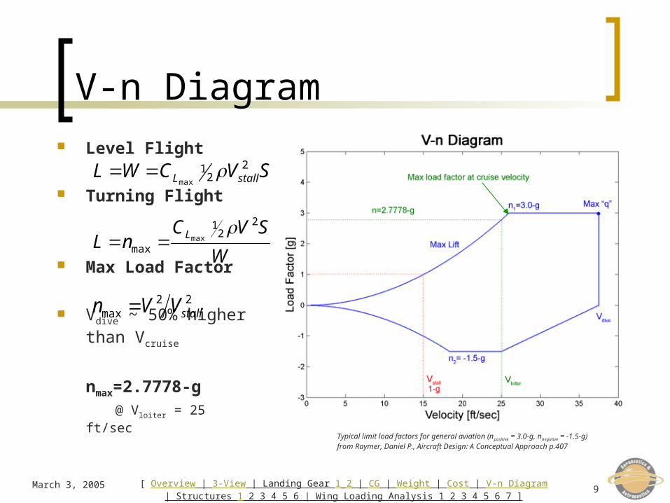
Properties of Wing Box
Shear Web 1.6 in. x 0.125 in. (0.1333 ft. x 0.0104 ft.) Two stringers: 0.25 in. x 0.25 in. (0.0208 ft. x 0.0208 ft.)
Wing Spar Central I beam located at maximum wing thickness With shear web and two stringers
Ribs 20 ribs spaced approximately every 3 inches
Stringers 0.375 in. x 0.375 in. (0.03125 ft. x 0.03125 ft.)
leading edge stringer 0.375 in. x 0.75 in. (0.03125 ft. x 0.0625 ft.)
trailing edge stringer for mounting aileron
March 3, 2005 11[ Overview | 3-View | Landing Gear 1 2 | CG | Weight | Cost | V-n Diagram
| Structures 1 2 3 4 5 6 | Wing Loading Analysis 1 2 3 4 5 6 7 ]
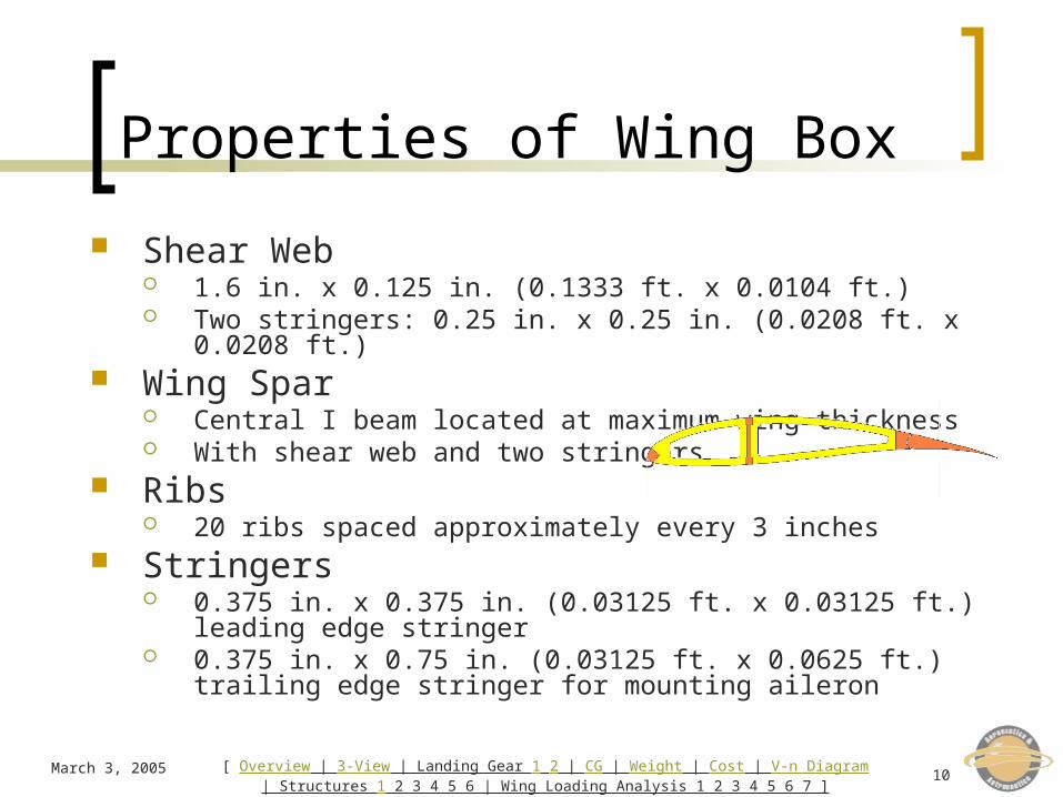
Material Properties
Density (lbf/ft3) Young’s Modulus (ksi) Yield Stress (psi)
Balsa 11 625 1725
Spruce 34 1500 8600
EPS Foam 1.5 320-360 72.5
EPP Foam 1.3 1000 4000
Epoxy 0.0625 lb/ft2 500 14500
Ultrakote 0.0156 lb/ft2 N/A N/A
Values from Fall ’04 AAE 451 projects and http://www.matweb.com

March 3, 2005 12[ Overview | 3-View | Landing Gear 1 2 | CG | Weight | Cost | V-n Diagram
| Structures 1 2 3 4 5 6 | Wing Loading Analysis 1 2 3 4 5 6 7 ]
Balsa construction Lightweight Simple, quick construction
Ultrakote wing covering All parts: 11 lbf/ft3 balsa High safety factor
(oversized web/stringers)
Structural Geometry

March 3, 2005 13[ Overview | 3-View | Landing Gear 1 2 | CG | Weight | Cost | V-n Diagram
| Structures 1 2 3 4 5 6 | Wing Loading Analysis 1 2 3 4 5 6 7 ]
Wing – Fuselage Attachment

March 3, 2005 14[ Overview | 3-View | Landing Gear 1 2 | CG | Weight | Cost | V-n Diagram
| Structures 1 2 3 4 5 6 | Wing Loading Analysis 1 2 3 4 5 6 7 ]
Fuselage Structure
Formers Outer Fuselage (each):
Six - 1” radius Main Fuselage:
Four - 2” radiusOne - 1” radius
Stringers Outer Fuselage (each):
Seven – 1/8” x 1/8” x 36” One – 1/8” x 1/2” x 36” (for landing gear mounts)
Main Fuselage:Eight – 1/8” x 1/8” x 20”
Balsa sticks
March 3, 2005 15[ Overview | 3-View | Landing Gear 1 2 | CG | Weight | Cost | V-n Diagram
| Structures 1 2 3 4 5 6 | Wing Loading Analysis 1 2 3 4 5 6 7 ]
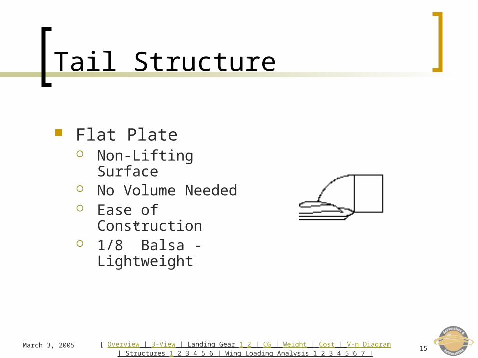
Tail Structure
Flat Plate Non-Lifting Surface No Volume Needed Ease of
Construction 1/8” Balsa -
Lightweight

March 3, 2005 16[ Overview | 3-View | Landing Gear 1 2 | CG | Weight | Cost | V-n Diagram
| Structures 1 2 3 4 5 6 | Wing Loading Analysis 1 2 3 4 5 6 7 ]
Wing Loading Analysis
Moments and Products of Inertia Constraints Analysis
Load Distribution at Maximum Wing Loading
Maximum Wing Root Bending Moment Maximum Torsional Moment Maximum Wing Tip Deflection
March 3, 2005 17[ Overview | 3-View | Landing Gear 1 2 | CG | Weight | Cost | V-n Diagram
| Structures 1 2 3 4 5 6 | Wing Loading Analysis 1 2 3 4 5 6 7 ]
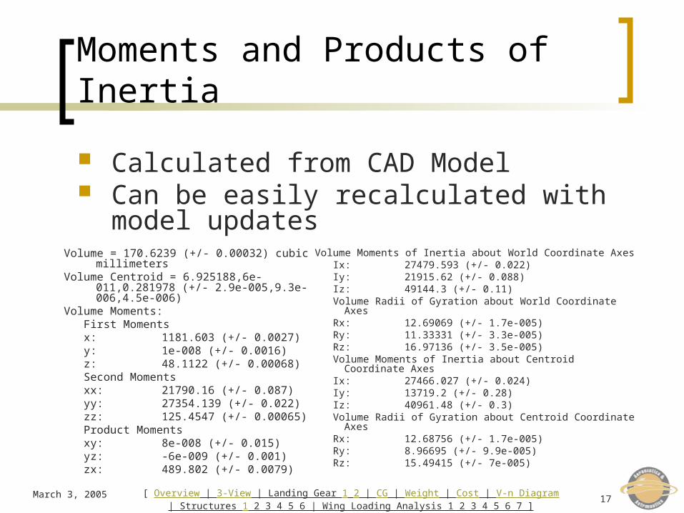
Moments and Products of Inertia
Volume Moments of Inertia about World Coordinate Axes Ix: 27479.593 (+/- 0.022) Iy: 21915.62 (+/- 0.088) Iz: 49144.3 (+/- 0.11) Volume Radii of Gyration about World Coordinate Axes Rx: 12.69069 (+/- 1.7e-005) Ry: 11.33331 (+/- 3.3e-005) Rz: 16.97136 (+/- 3.5e-005) Volume Moments of Inertia about Centroid Coordinate Axes Ix: 27466.027 (+/- 0.024) Iy: 13719.2 (+/- 0.28) Iz: 40961.48 (+/- 0.3) Volume Radii of Gyration about Centroid Coordinate Axes Rx: 12.68756 (+/- 1.7e-005) Ry: 8.96695 (+/- 9.9e-005) Rz: 15.49415 (+/- 7e-005)
Volume = 170.6239 (+/- 0.00032) cubic millimeters
Volume Centroid = 6.925188,6e-011,0.281978 (+/- 2.9e-005,9.3e-006,4.5e-006)
Volume Moments: First Moments x: 1181.603 (+/- 0.0027) y: 1e-008 (+/- 0.0016) z: 48.1122 (+/- 0.00068) Second Moments xx: 21790.16 (+/- 0.087) yy: 27354.139 (+/- 0.022) zz: 125.4547 (+/- 0.00065) Product Moments xy: 8e-008 (+/- 0.015) yz: -6e-009 (+/- 0.001) zx: 489.802 (+/- 0.0079)
Calculated from CAD Model Can be easily recalculated with model
updates

March 3, 2005 18[ Overview | 3-View | Landing Gear 1 2 | CG | Weight | Cost | V-n Diagram
| Structures 1 2 3 4 5 6 | Wing Loading Analysis 1 2 3 4 5 6 7 ]
Bending
Worst case simplification cantilevered beam uniform load distribution negligible outer fuselage mass/support
0q
March 3, 2005 19[ Overview | 3-View | Landing Gear 1 2 | CG | Weight | Cost | V-n Diagram
| Structures 1 2 3 4 5 6 | Wing Loading Analysis 1 2 3 4 5 6 7 ]
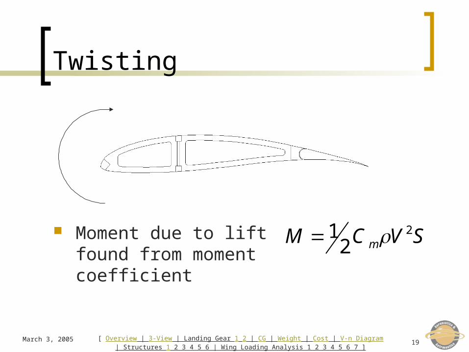
Twisting
Moment due to lift found from moment coefficient
212 mM C V S

March 3, 2005 20[ Overview | 3-View | Landing Gear 1 2 | CG | Weight | Cost | V-n Diagram
| Structures 1 2 3 4 5 6 | Wing Loading Analysis 1 2 3 4 5 6 7 ]
Constraints
Twisting: less than one degree of twist
Bending: bending stress less than balsa yield stress (w/ safety factor of 2)
ML
GI 21
2 mM C V S
My
I 2
01
2M q L

March 3, 2005 21[ Overview | 3-View | Landing Gear 1 2 | CG | Weight | Cost | V-n Diagram
| Structures 1 2 3 4 5 6 | Wing Loading Analysis 1 2 3 4 5 6 7 ]
Analysis
Maximum wing load: 1.97 lbs of lift, assuming uniform
distribution and span Maximum bending moment (at root):
1.308 ft-lbs
Maximum torsional moment (from Cm): 0.194 ft-lbs

March 3, 2005 22[ Overview | 3-View | Landing Gear 1 2 | CG | Weight | Cost | V-n Diagram
| Structures 1 2 3 4 5 6 | Wing Loading Analysis 1 2 3 4 5 6 7 ]
Maximum Wing Tip Vertical Deflection
Wing loading updated from uniform load to an elliptical distribution
Load assumed concentrated on central I beam section
Maximum tip deflection: 0.3605 in.

March 3, 2005 23[ Overview | 3-View | Landing Gear 1 2 | CG | Weight | Cost | V-n Diagram
| Structures 1 2 3 4 5 6 | Wing Loading Analysis 1 2 3 4 5 6 7 ]
Summary
Landing Gear Center of Gravity Weight and Cost Estimation V-n Diagram Structures
Wing Fuselage Tail
Wing Loading Analysis
Questions?

March 3, 2005 24[ Overview | 3-View | Landing Gear 1 2 | CG | Weight | Cost | V-n Diagram
| Structures 1 2 3 4 5 6 | Wing Loading Analysis 1 2 3 4 5 6 7 ]
Appendix

March 3, 2005 25[ Overview | 3-View | Landing Gear 1 2 | CG | Weight | Cost | V-n Diagram
| Structures 1 2 3 4 5 6 | Wing Loading Analysis 1 2 3 4 5 6 7 ]
Airfoil Selection: Wing
Wortmann FX 63-137
Wortmann FX 63-137: M.S.Selig,J.F.Donovan and D.B.Fraser,"AIRFOIL AT LOW SPEEDS” – Wind Tunnel
March 3, 2005 26[ Overview | 3-View | Landing Gear 1 2 | CG | Weight | Cost | V-n Diagram
| Structures 1 2 3 4 5 6 | Wing Loading Analysis 1 2 3 4 5 6 7 ]
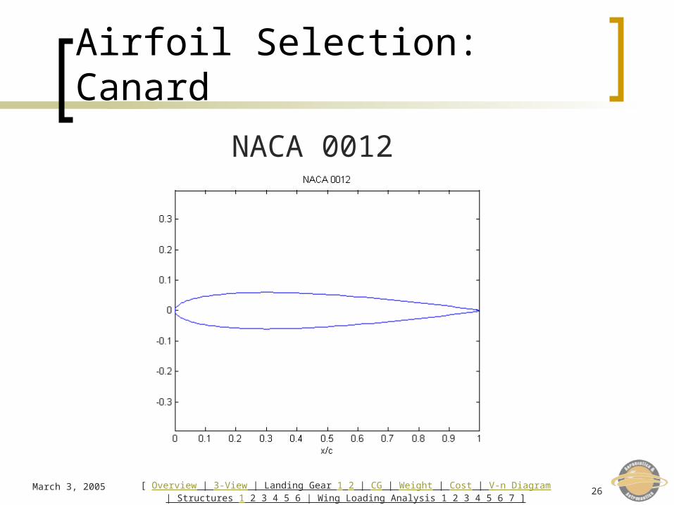
Airfoil Selection: Canard
NACA 0012
March 3, 2005 27[ Overview | 3-View | Landing Gear 1 2 | CG | Weight | Cost | V-n Diagram
| Structures 1 2 3 4 5 6 | Wing Loading Analysis 1 2 3 4 5 6 7 ]
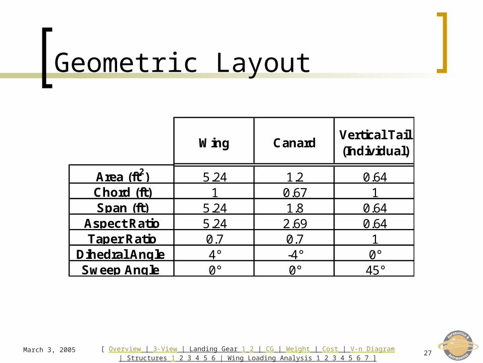
Geometric Layout
Wing Canard Vertical Tail (Individual)
Area (ft2) 5.24 1.2 0.64Chord (ft) 1 0.67 1Span (ft) 5.24 1.8 0.64
Aspect Ratio 5.24 2.69 0.64Taper Ratio 0.7 0.7 1
Dihedral Angle 4° -4° 0°Sweep Angle 0° 0° 45°
Related Documents