MAR-2000 Hardware User’s Manual Edition 2.0, February 2017 www.moxa.com/product © 2017 Moxa Inc. All rights reserved.

Welcome message from author
This document is posted to help you gain knowledge. Please leave a comment to let me know what you think about it! Share it to your friends and learn new things together.
Transcript

MAR-2000 Hardware User’s Manual
Edition 2.0, February 2017
www.moxa.com/product
© 2017 Moxa Inc. All rights reserved.

MAR-2000 Hardware User’s Manual
The software described in this manual is furnished under a license agreement and may be used only in accordance with the terms of that agreement.
Copyright Notice
© 2017 Moxa Inc. All rights reserved.
Trademarks
The MOXA logo is a registered trademark of Moxa Inc. All other trademarks or registered marks in this manual belong to their respective manufacturers.
Disclaimer
Information in this document is subject to change without notice and does not represent a commitment on the part of Moxa. Moxa provides this document as is, without warranty of any kind, either expressed or implied, including, but not limited to, its particular purpose. Moxa reserves the right to make improvements and/or changes to this manual, or to the products and/or the programs described in this manual, at any time. Information provided in this manual is intended to be accurate and reliable. However, Moxa assumes no responsibility for its use, or for any infringements on the rights of third parties that may result from its use. This product might include unintentional technical or typographical errors. Changes are periodically made to the information herein to correct such errors, and these changes are incorporated into new editions of the publication.
Technical Support Contact Information
www.moxa.com/support
Moxa Americas Toll-free: 1-888-669-2872 Tel: +1-714-528-6777 Fax: +1-714-528-6778
Moxa China (Shanghai office) Toll-free: 800-820-5036 Tel: +86-21-5258-9955 Fax: +86-21-5258-5505
Moxa Europe Tel: +49-89-3 70 03 99-0 Fax: +49-89-3 70 03 99-99
Moxa Asia-Pacific Tel: +886-2-8919-1230 Fax: +886-2-8919-1231
Moxa India Tel: +91-80-4172-9088 Fax: +91-80-4132-1045
Table of Contents
1. Introduction ...................................................................................................................................... 1-1 Overview ........................................................................................................................................... 1-2 Package Checklist ............................................................................................................................... 1-2 Product Features ................................................................................................................................ 1-2 Product Hardware Specifications ........................................................................................................... 1-3
2. Appearance and Dimensions ............................................................................................................. 2-1 Appearance ........................................................................................................................................ 2-2 Dimensions ........................................................................................................................................ 2-3 Hardware Block Diagram ..................................................................................................................... 2-4 LED Indicators .................................................................................................................................... 2-4 Reset Button ...................................................................................................................................... 2-5 Real Time Clock .................................................................................................................................. 2-5
3. Mounting Options .............................................................................................................................. 3-1 Wall or Cabinet Mounting ..................................................................................................................... 3-2 DIN Rail Assembly .............................................................................................................................. 3-2
4. Hardware Connection Description ..................................................................................................... 4-1 Wiring Requirements ........................................................................................................................... 4-2 Connecting the Power ......................................................................................................................... 4-2 Grounding the MAR-2000 .................................................................................................................... 4-3 Connecting to the Network ................................................................................................................... 4-3 Connecting a Serial Device ................................................................................................................... 4-3 Connecting to the Console Port ............................................................................................................. 4-4 CompactFlash .................................................................................................................................... 4-5 SIM Card ........................................................................................................................................... 4-6 USB .................................................................................................................................................. 4-6 Digital Inputs/Outputs ......................................................................................................................... 4-6
Digital Input Wiring ..................................................................................................................... 4-6 Digital Output Wiring ................................................................................................................... 4-6
A. Regulatory Approval Statements ....................................................................................................... A-1

1 1. Introduction
Thank you for purchasing the Moxa MAR-2000 programmable RISC-platform multi-WAN router.
The MAR-2000 is a multi-WAN router with 802.11n, GPS, and 3G GSM/HSPA+ interfaces. It features 2 RS-232/422/485 serial ports, 2 Ethernet ports, 4 digital input channels, 4 digital output channels, a CompactFlash socket, and 2 USB 2.0 ports. The MAR-2000 is particularly well-suited for rolling stock or other vehicle applications, giving a solid, convenient foundation for configuring an intelligent, cost-effective, multiple-WAN mobile communications environment.
This manual introduces the hardware of the MAR-2000 multi-WAN router, with a focus on installing and configuring the hardware.
The following topics are covered in this chapter:
Overview
Package Checklist
Product Features
Product Hardware Specifications

MAR-2000 Hardware Introduction
1-2
Overview The MAR-2000 series is a compact programmable RISC-based wireless mobile router with strong wireless routing capabilities. Featuring a built-in GPS module, HSPA+ cellular and 802.11 a/b/g/n wireless capabilities, independent power switches on its cellular module connectors and high thermal tolerance, the MAR-2000 is compliant with a portion of EN 50155 specifications. The built-in 32 MB NOR Flash ROM and 512 MB SDRAM give you enough memory to your application software, and the 512 MB NAND Flash can be used to provide additional data storage. The MAR-2000 also provides one CompactFlash socket for future storage expansion. The built-in GPS module supports geo-fencing functionality, making it ideal for managing wireless connections in cross-WAN environments, such as are found in rolling stock or other vehicle applications.
The MAR-2000 offers optimal data routing with the built-in dynamic routing feature. When a train travels to a different region, it often faces different wireless interface switches, such as WiFi, UMTS and HSPA+. Through multiple-WAN support and backup, the MAR-2000 helps ensure that your wireless connections are always available.
The MAR-2000 series includes wide temperature models designed to operate reliably in extreme temperatures ranging from -25 to 70°C.
The MAR-2000 provides an easy way to configure the routing between your various network interfaces. Advantages of MAR-2000 include the following:
• Intelligent policy configuration: Users can easily automate system configuration for heterogeneous networks.
• Multiple routing technology: Network bandwidth efficiency is easily optimized and network traffic jams are easily avoided.
Package Checklist All models of the MAR-2000 Series are shipped with the following items:
• 1 MAR-2000 multi-WAN router • Wallmount assembly • DIN rail mount assembly • CBL-4PINDB9F-100: 100 cm 4-pin-to-DB9 (female-to-female) console port cable, to connect to the
onboard 4-pin male RS-232 header connector • Quick installation guide • Documentation & software CD • Warranty card
NOTE: Please notify your sales representative if any of the above items are missing or damaged.
Product Features • Intel XScale IXP435 processor, 533 MHz • 512 MB DDR2 SDRAM • 512 MB NAND Flash for data storage • 32 MB NOR Flash to store OS • Multi-WAN dynamic routing • Policy-based routing management • Simple web management user interface • IEEE 802.11a/b/g/n wireless AP/bridge/client • Five-band UMTS/HSPA+ and quad-band GSM/GPRS/EDGE industrial IP-modems • Complies with a portion of EN 50155 specifications • Built-in 50-channel GPS for location-based applications • -25 to 70°C wide temperature range (EN 50155 Class T3)
MAR-2000 Hardware Introduction
1-3
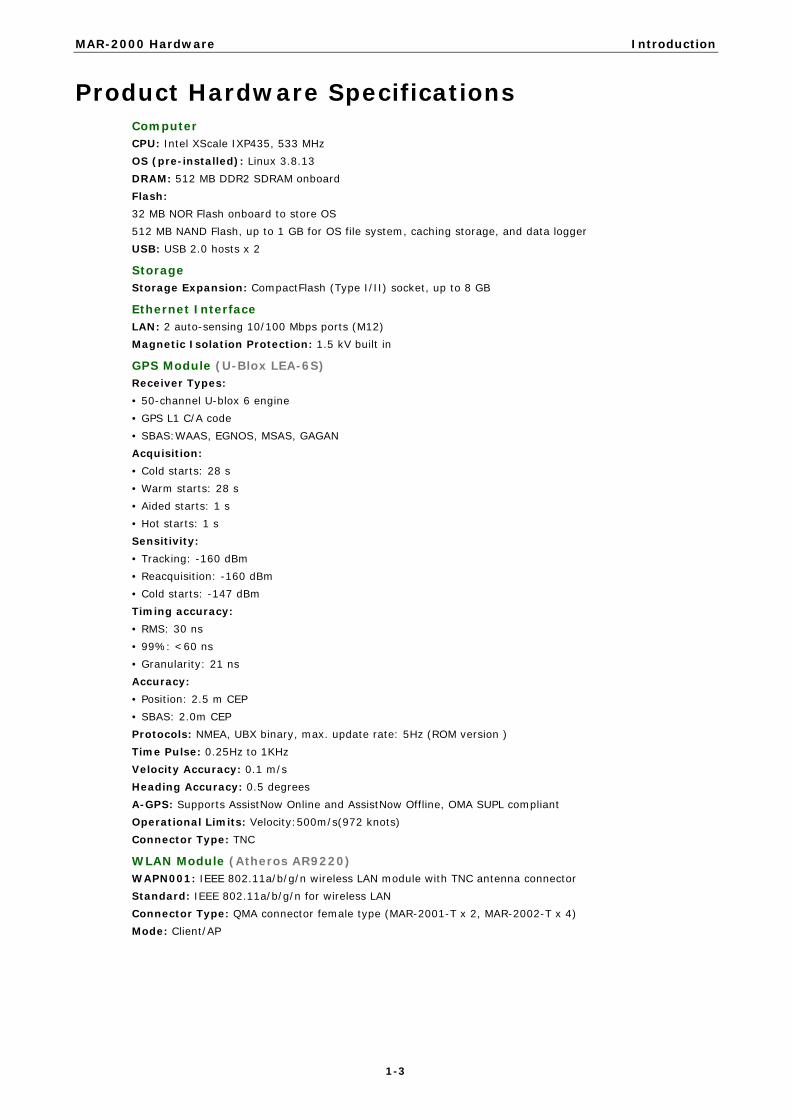
Product Hardware Specifications Computer CPU: Intel XScale IXP435, 533 MHz OS (pre-installed): Linux 3.8.13 DRAM: 512 MB DDR2 SDRAM onboard Flash: 32 MB NOR Flash onboard to store OS 512 MB NAND Flash, up to 1 GB for OS file system, caching storage, and data logger USB: USB 2.0 hosts x 2
Storage Storage Expansion: CompactFlash (Type I/II) socket, up to 8 GB
Ethernet Interface LAN: 2 auto-sensing 10/100 Mbps ports (M12) Magnetic Isolation Protection: 1.5 kV built in
GPS Module (U-Blox LEA-6S) Receiver Types: • 50-channel U-blox 6 engine • GPS L1 C/A code • SBAS:WAAS, EGNOS, MSAS, GAGAN Acquisition: • Cold starts: 28 s • Warm starts: 28 s • Aided starts: 1 s • Hot starts: 1 s Sensitivity: • Tracking: -160 dBm • Reacquisition: -160 dBm • Cold starts: -147 dBm Timing accuracy: • RMS: 30 ns • 99%: <60 ns • Granularity: 21 ns Accuracy: • Position: 2.5 m CEP • SBAS: 2.0m CEP Protocols: NMEA, UBX binary, max. update rate: 5Hz (ROM version ) Time Pulse: 0.25Hz to 1KHz Velocity Accuracy: 0.1 m/s Heading Accuracy: 0.5 degrees A-GPS: Supports AssistNow Online and AssistNow Offline, OMA SUPL compliant Operational Limits: Velocity:500m/s(972 knots) Connector Type: TNC
WLAN Module (Atheros AR9220) WAPN001: IEEE 802.11a/b/g/n wireless LAN module with TNC antenna connector Standard: IEEE 802.11a/b/g/n for wireless LAN Connector Type: QMA connector female type (MAR-2001-T x 2, MAR-2002-T x 4) Mode: Client/AP

MAR-2000 Hardware Introduction
1-4
Cellular Module (Cinterion PH8) Frequency Bands: GSM/GPRS/EDGE/UMTS/HSPA+ Band Options: • Five band UMTS(WCDMA/FDD) • 800/850/1900 AWS and 2100 MHz • Quad-band GSM: 850/900/1800/1900 MHz HSDPA/HSUPA Data Rates: DL: 3.6/7.2/14.4 Mbps; UL: 2.0/5.76 Mbps UMTS Data Rates: DL: max 384 Kbps; UL: max 384 Kbps EDGE Class 12: DL: max 237 Kbps; UL: max 237 Kbps GPRS Class 12: DL: max 85.6 Kbps; UL: max 85.6 Kbps Connector Type: QMA connector female type (MAR-2001-T x 2, MAR-2002-T x 3)
Serial Interface Serial Standards: 2 RS-232/422/485 ports, software-selectable (DB9) Console Port: RS-232 (TxD, RxD, GND), 4-pin pin header output (115200, n, 8, 1)
Serial Signals RS-232: TxD, RxD, DTR, DSR, RTS, CTS, DCD, GND RS-422: TxD+, TxD-, RxD+, RxD-, GND RS-485-4w: TxD+, TxD-, RxD+, RxD-, GND RS-485-2w: Data+, Data-, GND
Serial Communication Parameters Data Bits: 5, 6, 7, 8 Stop Bits: 1, 1.5, 2 Parity: None, Even, Odd, Space, Mark Flow Control: RTS/CTS, XON/XOFF, ADDC® (automatic data direction control) for RS-485 Baudrate: 50 bps to 921.6 Kbps (supports non-standard baudrates; see user’s manual for details)
Digital Input Input Channels: 4, source type Input Voltage: 0 to 30 VDC Digital Input Levels for Dry Contacts: • Logic level 0: Close to GND • Logic level 1: Open Digital Input Levels for Wet Contacts: • Logic level 0: +3 V max. • Logic level 1: +10 V to +30 V (COM to DI) Connector Type: 10-pin screw terminal block (4 points, COM, GND) Isolation: 2 KV optical isolation
Digital Output Output Channels: 4, sink type Output Current: Max. 200 mA per channel On-state Voltage: 24 VDC nominal, open collector to 30 V Connector Type: 10-pin screw terminal block (4 points, GND)
LEDs System: Power, Ready, Storage, Programmable LAN: 10M/Link x 2, 100M/Link x 2 (on connector) Serial: TxD x 2, RxD x 2 Reset Button: Supports “Reset to Factory Default”

MAR-2000 Hardware Introduction
1-5
Physical Characteristics Housing: SECC sheet metal (1 mm) Weight: 1.2 kg Dimensions: 200 x 57 x 120 mm (7.87 x 2.24 x 4.72 in) Mounting: DIN rail, wall
Environmental Limits Operating Temperature: Standard Models: -25 to 55°C (-13 to 131°F) Wide Temp. Models: -25 to 70°C (-13 to 158°F) Storage Temperature: Standard Models: -25 to 75°C (-13 to 167°F) Wide Temp. Models: -40 to 80°C (-40 to 176°F) Ambient Relative Humidity: 5 to 95% (non-condensing) Anti-vibration: IEC 61373 standard Anti-shock: IEC 61373 standard
Power Requirements Input Voltage: 24 VDC (9 to 48 V), M12 connector Power Consumption: 20 W • 833 mA @ 24 VDC
Standards and Certifications Safety: UL 60950-1 EMC: EN 55032 Class A, EN 61000-4-2, EN 61000-4-3, EN 61000-4-4, FCC Part 15 Subpart B Class A Rail Traffic: EN 50155*, EN 50121-4, IEC 61373 *Complies with a portion of EN 50155 specifications. Please contact Moxa or a Moxa distributor for details.
Reliability Alert Tools: Built-in buzzer and RTC (real-time clock)
Warranty Warranty Period: 5 years (does not apply to cellular module) Details: See www.moxa.com/warranty Note: These hardware specifications describe the embedded computer unit itself, but not its official accessories. In particular, the wide temperature specification does not apply to accessories such as power adaptors and cables.

2 2. Appearance and Dimensions
The following topics are covered in this chapter:
Appearance
Dimensions
Hardware Block Diagram
LED Indicators
Reset Button
Real Time Clock

MAR-2000 Hardware Appearance and Dimensions
2-2
Appearance Front View
Top View
Rear View
NOTE The Configuration Switch, which is for turning on the power, is available by request

MAR-2000 Hardware Appearance and Dimensions
2-3
Dimensions
Unit = mm (inch)
MAR-2001-T
MAR-2002-T

MAR-2000 Hardware Appearance and Dimensions
2-4
Hardware Block Diagram The following block diagram shows the layout of the MAR-2000’s internal components.
LED Indicators The MAR-2000 has 14 LED indicators on the top panel. Refer to the following table for information about each LED.
LED Name LED Color LED Function
Power Green Power is on and functioning normally
Off Power is off, or there is a power malfunction
Storage Yellow CF card has been detected
Off CF card has not been detected
Ready Green The system is ready
Off The system is not ready
X1 (programmable)
Green This LED must be defined by the user, as a “programmable function”
Off This LED must be defined by the user, as a “programmable function”
LAN (1, 2)
Green 100 Mbps Ethernet mode
Yellow 10 Mbps Ethernet mode
Off No LAN activity
Tx, Tx (P1-P2) Green Serial ports P1-P2 transmitting data
Off Serial ports P1-P2 not transmitting data
Rx, Rx (P1-P2) Yellow Serial ports P1-P2 receiving data
Off Serial ports P1-P2 not receiving data

MAR-2000 Hardware Appearance and Dimensions
2-5
Reset Button The button labeled Reset returns the MAR-2000 to its factory-default configuration.
Press the Reset button continuously for at least 5 seconds to load the factory-default configuration. After the factory defaults have been loaded, the system will reboot automatically. The Ready LED maintains a steady glow once the system has rebooted.
We recommend that you only use this function under extreme circumstances, such as when the software is not working properly and you must reload the device’s default settings.
WARNING
Existing configuration will be erased after the you reset the device to the factory defaults."
Real Time Clock The MAR-2000’s real time clock is powered by a lithium battery. We strongly recommend that you do not replace the lithium battery without help from a qualified Moxa support engineer. If you need to change the battery, contact the Moxa RMA service team.
WARNING
There is a risk of explosion if the battery is replaced by an incorrect type.

3 3. Mounting Options
The following topics are covered in this chapter:
Wall or Cabinet Mounting
DIN Rail Assembly

MAR-2000 Hardware Mounting Options
3-2
Wall or Cabinet Mounting The two metal brackets that come standard with the MAR-2000 are used to attach the MAR-2000 to a wall or the inside of a cabinet. First, use two screws (M3 type, torque 4.5±0.5 kgf-cm) per bracket to attach the brackets to the bottom of the MAR-2000 (Fig. A). Next, use two screws per bracket to attach the MAR-2000 to a wall or cabinet (Fig. B).
Figure A: MAR-2000 Embedded Computer—Wall Mounting Assembly (bottom view)
Figure B: MAR-2000 Embedded Computer—Wall Mounting Assembly (top view)
DIN Rail Assembly An aluminum DIN rail attachment plate is included with the product. When attaching the rail mount to the MAR-2000, make sure the metal spring is situated towards the top, as shown in the following figures.
STEP 1: Insert the top of the DIN rail into the slot, just below the stiff metal spring.
STEP 2: The DIN rail attachment unit will snap into place as shown below.
To remove the MAR-2000 from the DIN rail, simply reverse Steps 1 and 2.

4 4. Hardware Connection Description
This section describes how to connect the MAR-2000 to serial devices for initial testing purposes.
The following topics are covered in this chapter:
Wiring Requirements
Connecting the Power
Grounding the MAR-2000
Connecting to the Network
Connecting a Serial Device
Connecting to the Console Port
CompactFlash
SIM Card
USB
Digital Inputs/Outputs
Digital Input Wiring
Digital Output Wiring

MAR-2000 Hardware Hardware Connection Description
4-2
Wiring Requirements
ATTENTION
Safety First! Be sure to disconnect the power cord before installing and/or wiring your MAR-2000.
Wiring Caution! Calculate the maximum possible current in each power wire and common wire. Observe all electrical codes dictating the maximum current allowable for each wire size. If the current goes above the maximum ratings, the wiring could overheat, causing serious damage to your equipment.
Temperature Caution! Be careful when handling the MAR-2000. When plugged in, the MAR-2000’s internal components generate heat, and the outer casing may feel hot to the touch.
You should also observe the following common wiring rules:
• Use separate paths to route wiring for power and devices. If power wiring and device wiring paths must cross, make sure the wires are perpendicular at the intersection point. NOTE: Do not run signal or communication wiring and power wiring in the same wire conduit. To avoid interference, wires with different signal characteristics should be routed separately.
• You can use the type of signal transmitted through a wire to determine which wires should be kept separate. The rule of thumb is that wiring that shares similar electrical characteristics can be bundled together.
• Keep input wiring and output wiring separate. • Where necessary, we strongly recommend that you label all system wiring, for all devices in the system.
Connecting the Power The MAR-2000 has a 5-pin M12 connector for the 24 VDC power input (see the attention note below).
The following figures show how the power input connects to an external power source. If the power is properly supplied, the Ready LED turns solid green after about five minutes.
ATTENTION
The power for this product should be supplied by a listed power supply unit rated to deliver 12 to 48 VDC at a minimum of 1280 mA for 12 VDC, and 300 mA for 48 VDC.

MAR-2000 Hardware Hardware Connection Description
4-3
Grounding the MAR-2000 Grounding and wire routing help limit the effects of noise from electromagnetic interference (EMI). Run the ground connection from the ground screw to the grounding surface prior to connecting devices.
ATTENTION
This product is intended to be mounted to a well-grounded mounting surface, such as a metal panel.
SG: The Grounding Connector and the central pin in the power connector (see the figure to the left) are on the same grounding plane and should both be properly connected to a shielding ground.
Connecting to the Network Connect one end of the Ethernet cables to one of the MAR-2000’s 10/100M Ethernet ports (M12), and the other end of the cable to the Ethernet network. See the adjacent figure for the M12 Ethernet connector pin assignments:
Recommend M12 Connector and Cable
Connector M12D-4P-IP68: Field-installation D-coded screw-in Ethernet connector, 4-pin male M12 connector, IP68-rated
Cable CBL-M12D(MM4P)/RJ45-100 IP67: 1-meter D-coded M12-to-RJ45 Cat-5C UTP Ethernet cable, 4-pin male M12 connector, IP67-rated
Connecting a Serial Device Use properly wired serial cables to connect the MAR-2000 to serial devices. The MAR-2000’s serial ports (P1 to P2) use 9-pin male DB9 connectors. The ports can be configured for RS-232, RS-422, or 2-wire RS-485 from the MAR-2000’s management Web page. The pin assignments are shown in the following table:
Pin RS-232 RS-422/
RS-485-4w RS-485-2w
1 DCD TxD-(A) –
2 RxD TxD+(B) –
3 TxD RxD+(B) Data+(B)
4 DTR RxD-(A) Data-(A)
5 GND GND GND
6 DSR – –
7 RTS – –
8 CTS – –

MAR-2000 Hardware Hardware Connection Description
4-4
Connecting to the Console Port The MAR-2000’s console port is an RS-232 4-pin header connector. Refer to the following figure for pin assignments on the console port cable. Use the CBL-4PINDB9F-100 cable included with the MAR-2000 to connect a PC to the MAR-2000’s serial console port.
Pinouts for the Serial Console Port Serial Console Cable
Pin Signal
1 TxD 2 RxD 3 NC 4 GND
The console port is located just below the CompactFlash socket, on the opposite side of the motherboard. Use a screwdriver to remove the two screws that secure the cover to the embedded computer’s housing.
Refer to the following figure to see the precise location of the console port.

MAR-2000 Hardware Hardware Connection Description
4-5
CompactFlash The MAR-2000 provides one CompactFlash (CF) slot that supports CompactFlash type I/II card expansion.
WARNING
Be sure to power off the computer before inserting or removing the CompactFlash card.
The following description explains the installation process for CompactFlash cards.
You must remove the shell’s protective cover before you can access the CompactFlash socket. Two screws (shown at right) secure the cover in place.
The CF socket is located on the motherboard, as shown below.
If you need device drivers for other kinds of mass storage cards, contact Moxa for information on how to initiate a cooperative development project.

MAR-2000 Hardware Hardware Connection Description
4-6
SIM Card The MAR-2000 comes with three SIM card sockets that can be used to install three SIM cards for cellular communications. To insert a SIM card, remove the cover on the front panel and insert the SIM card into one of the three slots.
USB For additional storage expansion, the MAR-2000 provides two USB 2.0 ports on the rear panel.
Digital Inputs/Outputs The MAR-2000 has 4 digital outputs and 4 digital inputs. The pinouts for the I/O are shown in the following figures with suggested wiring:
Digital Input Wiring
Dry Contact
Wet Contact
Note: Power for wet contacts is supplied by the COM channel.
Digital Output Wiring

A A. Regulatory Approval Statements
This device complies with part 15 of the FCC Rules. Operation is subject to the following two conditions: (1) This device may not cause harmful interference, and (2) this device must accept any interference received, including interference that may cause undesired operation.
Related Documents