Top Banner
Mapping ER Diagram to a Relational Database Step 1:- Map the strong entities in the ER diagram. M1 For strong entities create a new table (relation)for each strong entity and make the indicated key of the strong entity the primary key of the table. If more than one candidate key is indicated on the ER diagram, choose one as the primary key for the table.
37

Mapping ER Diagram to a Relational Database · Mapping ER Diagram to a Relational Database Step 1:-Map the strong entities in the ER diagram. M1 — For strong entities — create

Mar 18, 2020

Download

Documents

dariahiddleston
Welcome message from author
This document is posted to help you gain knowledge. Please leave a comment to let me know what you think about it! Share it to your friends and learn new things together.
Transcript
Page 1: Mapping ER Diagram to a Relational Database · Mapping ER Diagram to a Relational Database Step 1:-Map the strong entities in the ER diagram. M1 — For strong entities — create

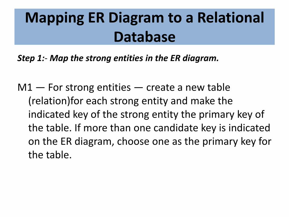
Mapping ER Diagram to a Relational Database

Step 1:- Map the strong entities in the ER diagram.

M1 — For strong entities — create a new table (relation)for each strong entity and make the indicated key of the strong entity the primary key of the table. If more than one candidate key is indicated on the ER diagram, choose one as the primary key for the table.

Page 2: Mapping ER Diagram to a Relational Database · Mapping ER Diagram to a Relational Database Step 1:-Map the strong entities in the ER diagram. M1 — For strong entities — create

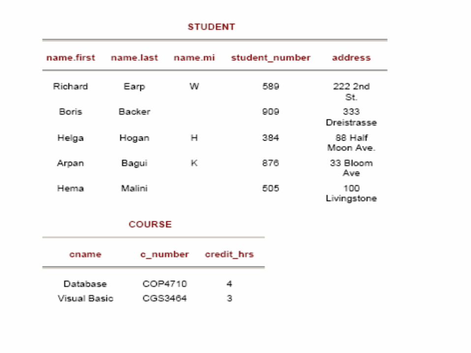
• M1a — Mapping atomic attributes from an entity — For entities with atomic attributes: Map entities to a table (relation) by forming columns from the atomic attributes for that entity.

• M1b — For entities with composite attributes, form columns from the elementary (atomic) parts of the composite attributes.

Page 3: Mapping ER Diagram to a Relational Database · Mapping ER Diagram to a Relational Database Step 1:-Map the strong entities in the ER diagram. M1 — For strong entities — create
Page 4: Mapping ER Diagram to a Relational Database · Mapping ER Diagram to a Relational Database Step 1:-Map the strong entities in the ER diagram. M1 — For strong entities — create

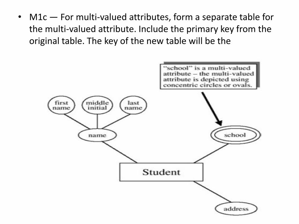
• M1c — For multi-valued attributes, form a separate table for the multi-valued attribute. Include the primary key from the original table. The key of the new table will be the

Page 5: Mapping ER Diagram to a Relational Database · Mapping ER Diagram to a Relational Database Step 1:-Map the strong entities in the ER diagram. M1 — For strong entities — create
Page 6: Mapping ER Diagram to a Relational Database · Mapping ER Diagram to a Relational Database Step 1:-Map the strong entities in the ER diagram. M1 — For strong entities — create

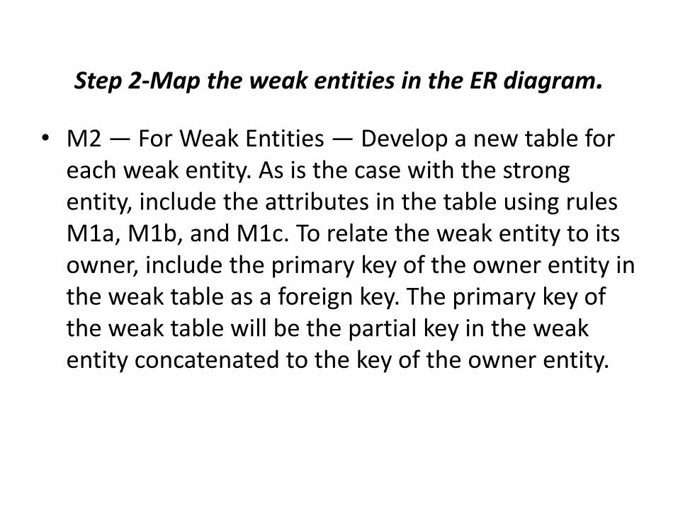
Step 2-Map the weak entities in the ER diagram.

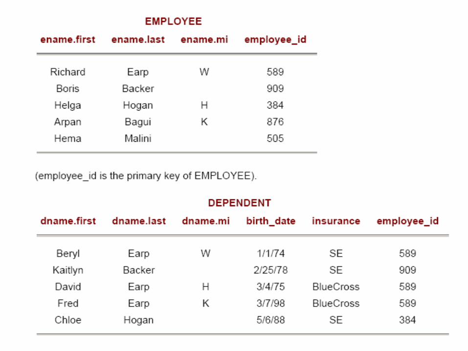
• M2 — For Weak Entities — Develop a new table for each weak entity. As is the case with the strong entity, include the attributes in the table using rules M1a, M1b, and M1c. To relate the weak entity to its owner, include the primary key of the owner entity in the weak table as a foreign key. The primary key of the weak table will be the partial key in the weak entity concatenated to the key of the owner entity.

Page 7: Mapping ER Diagram to a Relational Database · Mapping ER Diagram to a Relational Database Step 1:-Map the strong entities in the ER diagram. M1 — For strong entities — create
Page 8: Mapping ER Diagram to a Relational Database · Mapping ER Diagram to a Relational Database Step 1:-Map the strong entities in the ER diagram. M1 — For strong entities — create
Page 9: Mapping ER Diagram to a Relational Database · Mapping ER Diagram to a Relational Database Step 1:-Map the strong entities in the ER diagram. M1 — For strong entities — create
Page 10: Mapping ER Diagram to a Relational Database · Mapping ER Diagram to a Relational Database Step 1:-Map the strong entities in the ER diagram. M1 — For strong entities — create

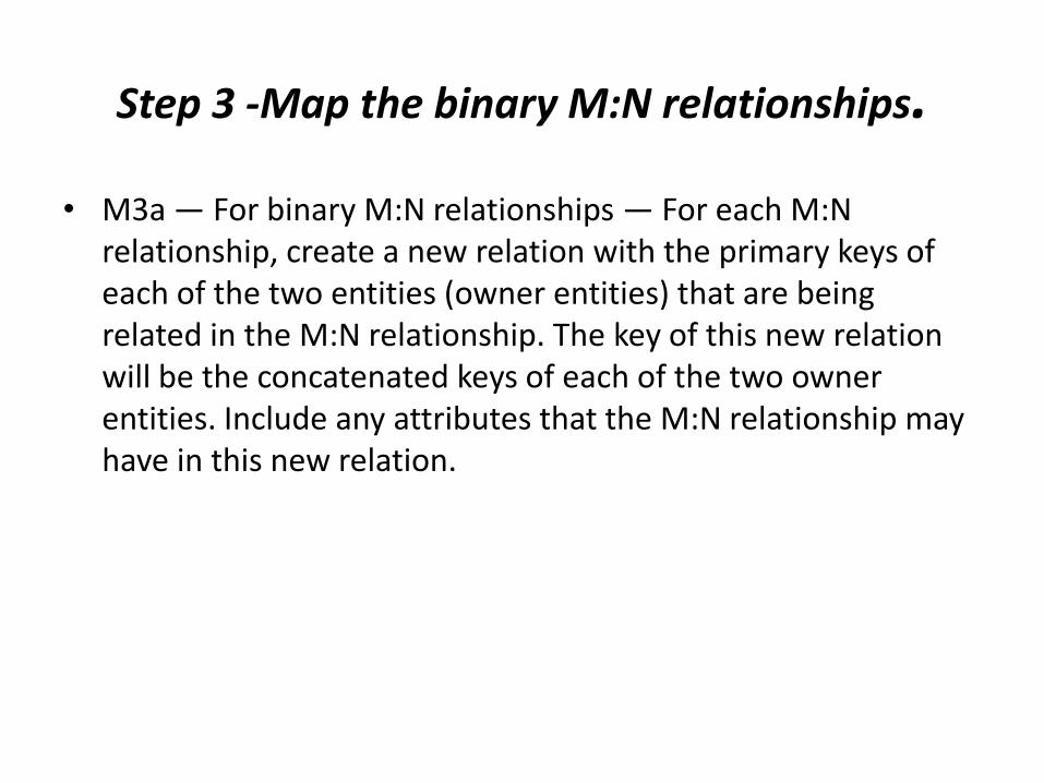
Step 3 -Map the binary M:N relationships.

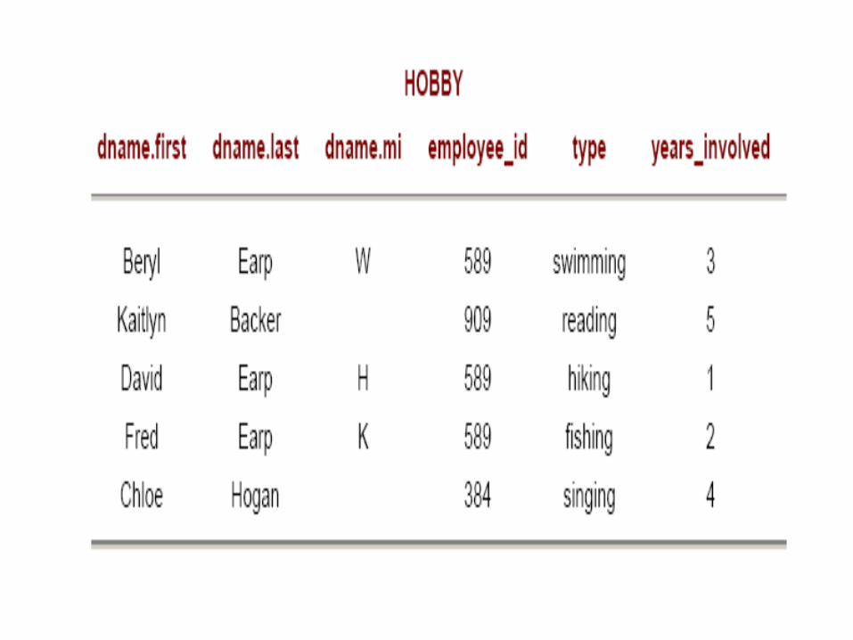
• M3a — For binary M:N relationships — For each M:N relationship, create a new relation with the primary keys of each of the two entities (owner entities) that are being related in the M:N relationship. The key of this new relation will be the concatenated keys of each of the two owner entities. Include any attributes that the M:N relationship may have in this new relation.

Page 11: Mapping ER Diagram to a Relational Database · Mapping ER Diagram to a Relational Database Step 1:-Map the strong entities in the ER diagram. M1 — For strong entities — create
Page 12: Mapping ER Diagram to a Relational Database · Mapping ER Diagram to a Relational Database Step 1:-Map the strong entities in the ER diagram. M1 — For strong entities — create
Page 13: Mapping ER Diagram to a Relational Database · Mapping ER Diagram to a Relational Database Step 1:-Map the strong entities in the ER diagram. M1 — For strong entities — create
Page 14: Mapping ER Diagram to a Relational Database · Mapping ER Diagram to a Relational Database Step 1:-Map the strong entities in the ER diagram. M1 — For strong entities — create

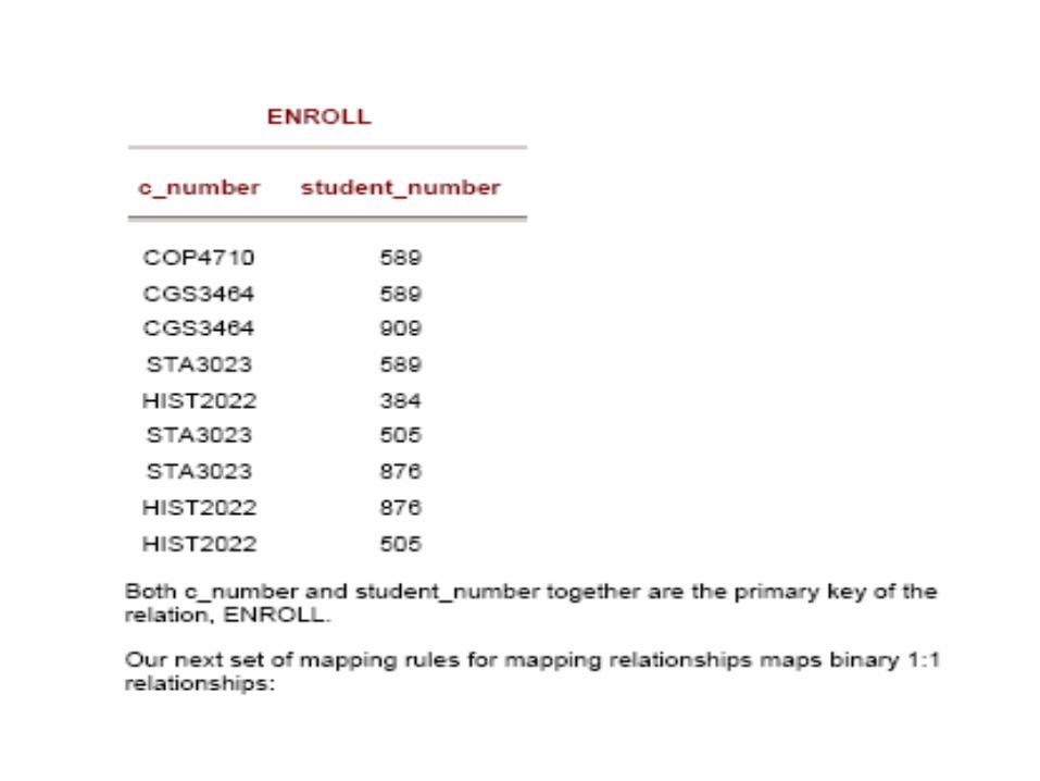
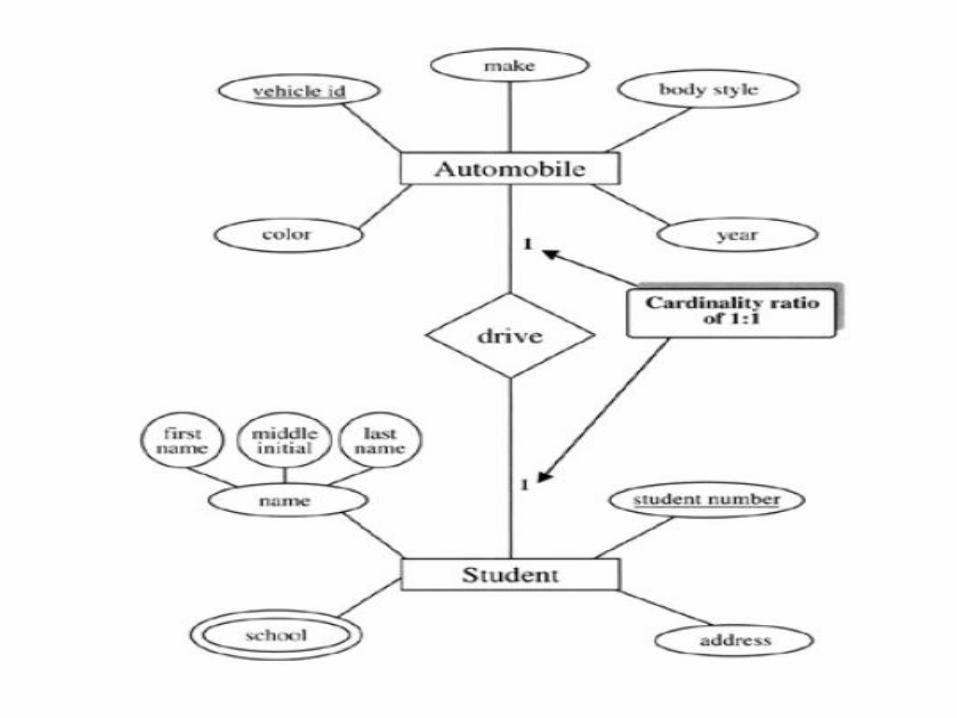
Step 4-Map the binary 1:1 relationships

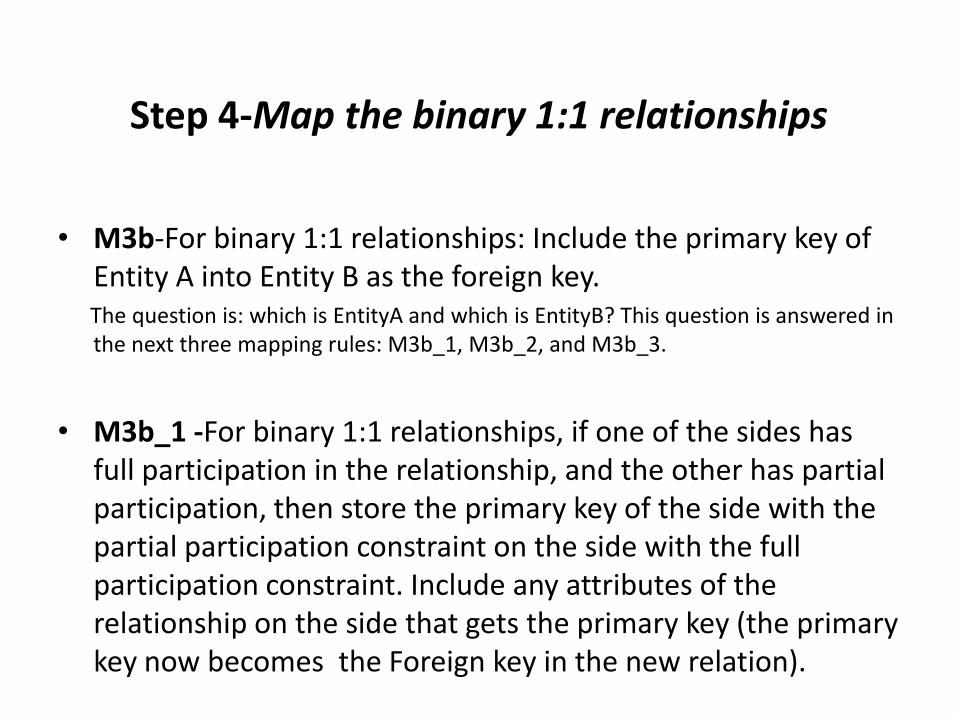
• M3b-For binary 1:1 relationships: Include the primary key of Entity A into Entity B as the foreign key.

The question is: which is EntityA and which is EntityB? This question is answered in the next three mapping rules: M3b_1, M3b_2, and M3b_3.

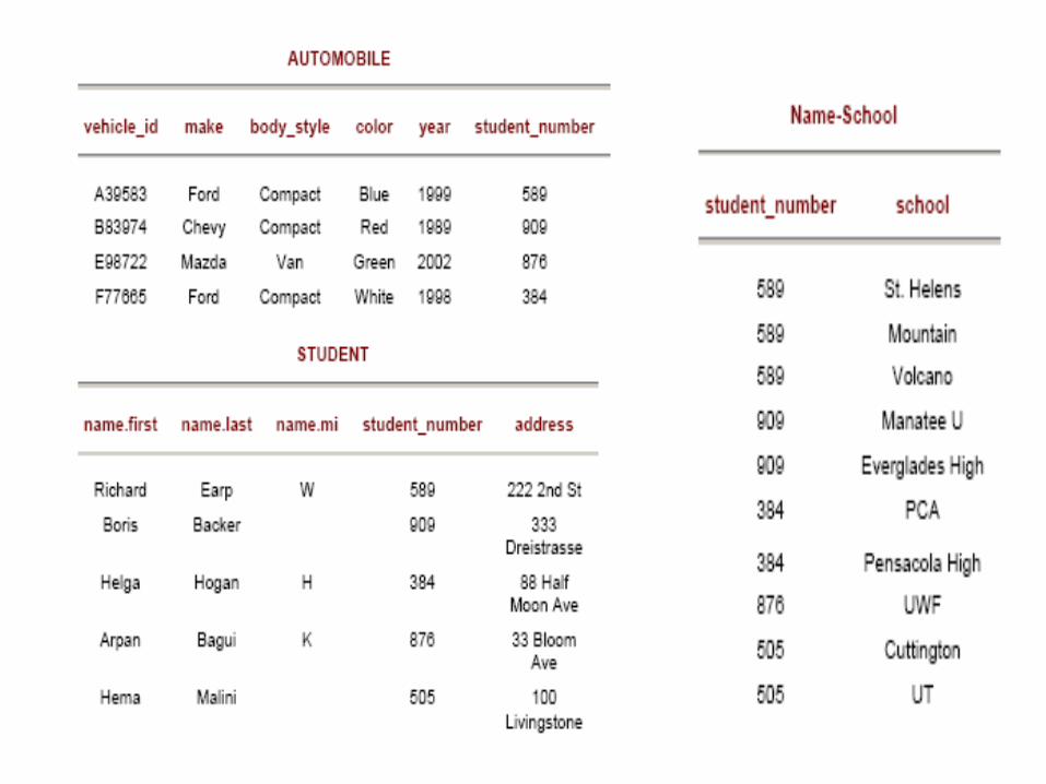
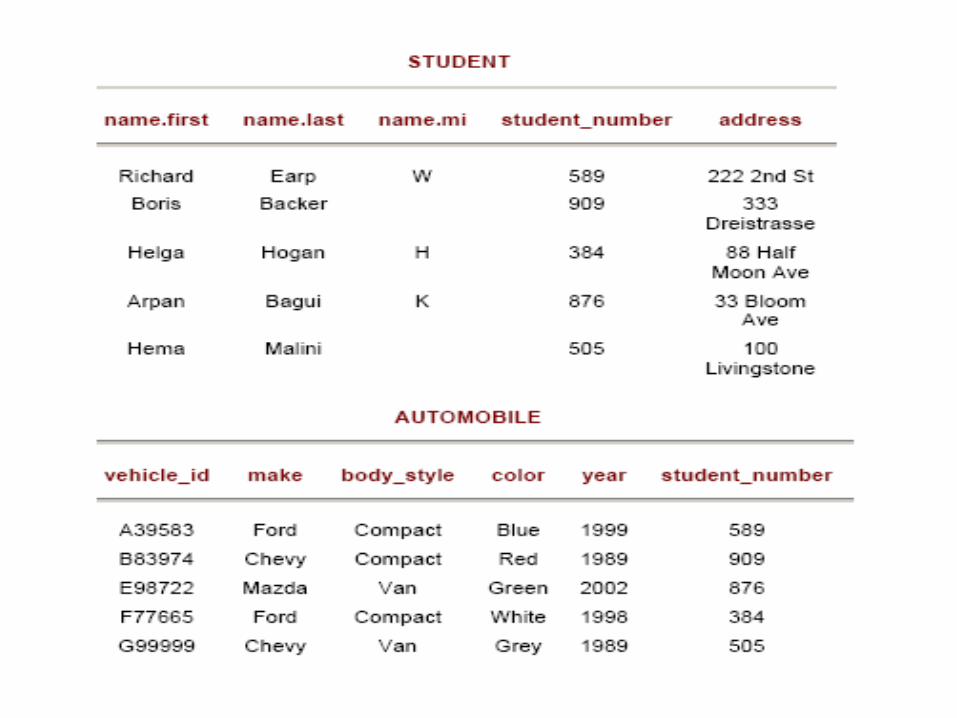
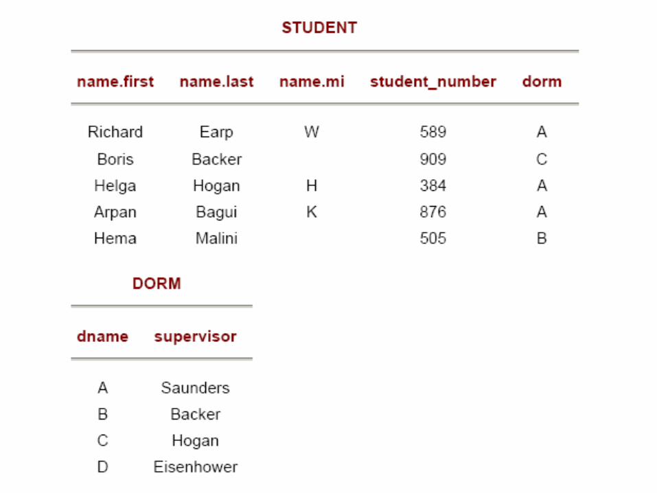
• M3b_1 -For binary 1:1 relationships, if one of the sides has full participation in the relationship, and the other has partial participation, then store the primary key of the side with the partial participation constraint on the side with the full participation constraint. Include any attributes of the relationship on the side that gets the primary key (the primary key now becomes the Foreign key in the new relation).

Page 15: Mapping ER Diagram to a Relational Database · Mapping ER Diagram to a Relational Database Step 1:-Map the strong entities in the ER diagram. M1 — For strong entities — create
Page 16: Mapping ER Diagram to a Relational Database · Mapping ER Diagram to a Relational Database Step 1:-Map the strong entities in the ER diagram. M1 — For strong entities — create
Page 17: Mapping ER Diagram to a Relational Database · Mapping ER Diagram to a Relational Database Step 1:-Map the strong entities in the ER diagram. M1 — For strong entities — create

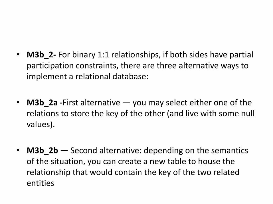
• M3b_2- For binary 1:1 relationships, if both sides have partial participation constraints, there are three alternative ways to implement a relational database:

• M3b_2a -First alternative — you may select either one of the relations to store the key of the other (and live with some null values).

• M3b_2b — Second alternative: depending on the semantics of the situation, you can create a new table to house the relationship that would contain the key of the two related entities

Page 18: Mapping ER Diagram to a Relational Database · Mapping ER Diagram to a Relational Database Step 1:-Map the strong entities in the ER diagram. M1 — For strong entities — create
Page 19: Mapping ER Diagram to a Relational Database · Mapping ER Diagram to a Relational Database Step 1:-Map the strong entities in the ER diagram. M1 — For strong entities — create
Page 20: Mapping ER Diagram to a Relational Database · Mapping ER Diagram to a Relational Database Step 1:-Map the strong entities in the ER diagram. M1 — For strong entities — create

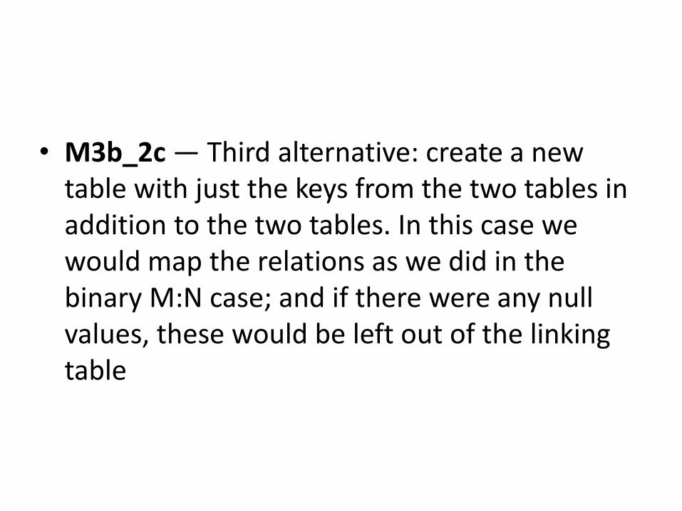
• M3b_2c — Third alternative: create a new table with just the keys from the two tables in addition to the two tables. In this case we would map the relations as we did in the binary M:N case; and if there were any null values, these would be left out of the linking table

Page 21: Mapping ER Diagram to a Relational Database · Mapping ER Diagram to a Relational Database Step 1:-Map the strong entities in the ER diagram. M1 — For strong entities — create
Page 22: Mapping ER Diagram to a Relational Database · Mapping ER Diagram to a Relational Database Step 1:-Map the strong entities in the ER diagram. M1 — For strong entities — create

• M3b_3 — For binary 1:1 relationships, if both sides have full participation constraints, you can use the semantics of the relationship to select which table should contain the key of the other. It would be inappropriate to include foreign keys in both tables as you would be introducing redundancy in the database. Include any attributes on the relationship, on the table that is getting the foreign key. This situation may be better handled using the new table rule M3a

Page 23: Mapping ER Diagram to a Relational Database · Mapping ER Diagram to a Relational Database Step 1:-Map the strong entities in the ER diagram. M1 — For strong entities — create
Page 24: Mapping ER Diagram to a Relational Database · Mapping ER Diagram to a Relational Database Step 1:-Map the strong entities in the ER diagram. M1 — For strong entities — create

Step 5: Map the binary 1:N relationships

• M3c — Although most binary 1:N relationships are mapped with the PK/FK method, the separate table per rule M3a can be used. To use the PK/FK method for binary 1:N relationships, we have to check what kind of participation constraints the N side of the relation has:

• M3c_1 — For binary 1:N relationships, if the N-side has full participation, include the key of the entity from the 1 side in the table on the N side as a foreign key in the N side table. If the N side is weak with no primary key, a key from the 1 side will be required in the N side table concatenated to the weak partial key. The key of this table will be the weak partial key plus the foreign key. Include any attributes that were on the relationship, in the table that is getting the foreign key (the N side).

Page 25: Mapping ER Diagram to a Relational Database · Mapping ER Diagram to a Relational Database Step 1:-Map the strong entities in the ER diagram. M1 — For strong entities — create
Page 26: Mapping ER Diagram to a Relational Database · Mapping ER Diagram to a Relational Database Step 1:-Map the strong entities in the ER diagram. M1 — For strong entities — create
Page 27: Mapping ER Diagram to a Relational Database · Mapping ER Diagram to a Relational Database Step 1:-Map the strong entities in the ER diagram. M1 — For strong entities — create

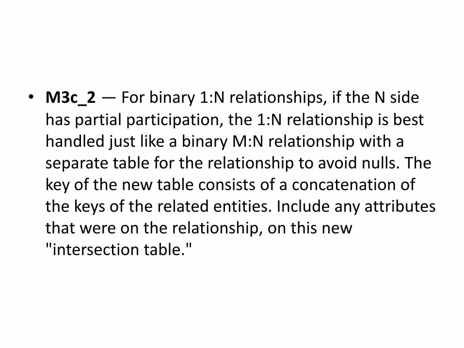
• M3c_2 — For binary 1:N relationships, if the N side has partial participation, the 1:N relationship is best handled just like a binary M:N relationship with a separate table for the relationship to avoid nulls. The key of the new table consists of a concatenation of the keys of the related entities. Include any attributes that were on the relationship, on this new "intersection table."

Page 28: Mapping ER Diagram to a Relational Database · Mapping ER Diagram to a Relational Database Step 1:-Map the strong entities in the ER diagram. M1 — For strong entities — create

Step 6: Map recursive relationships.

• M5 — For recursive entities, two types of mapping rules

have been developed:

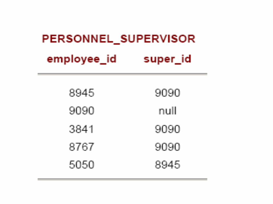
• M5a — For 1:N recursive relationships, reinclude the primary key of the table with the recursive relationship in the same table, giving the key some other name.

Page 29: Mapping ER Diagram to a Relational Database · Mapping ER Diagram to a Relational Database Step 1:-Map the strong entities in the ER diagram. M1 — For strong entities — create
Page 30: Mapping ER Diagram to a Relational Database · Mapping ER Diagram to a Relational Database Step 1:-Map the strong entities in the ER diagram. M1 — For strong entities — create
Page 31: Mapping ER Diagram to a Relational Database · Mapping ER Diagram to a Relational Database Step 1:-Map the strong entities in the ER diagram. M1 — For strong entities — create

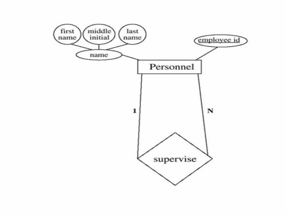
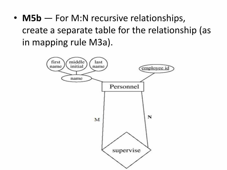
• M5b — For M:N recursive relationships, create a separate table for the relationship (as in mapping rule M3a).

Page 32: Mapping ER Diagram to a Relational Database · Mapping ER Diagram to a Relational Database Step 1:-Map the strong entities in the ER diagram. M1 — For strong entities — create
Page 33: Mapping ER Diagram to a Relational Database · Mapping ER Diagram to a Relational Database Step 1:-Map the strong entities in the ER diagram. M1 — For strong entities — create

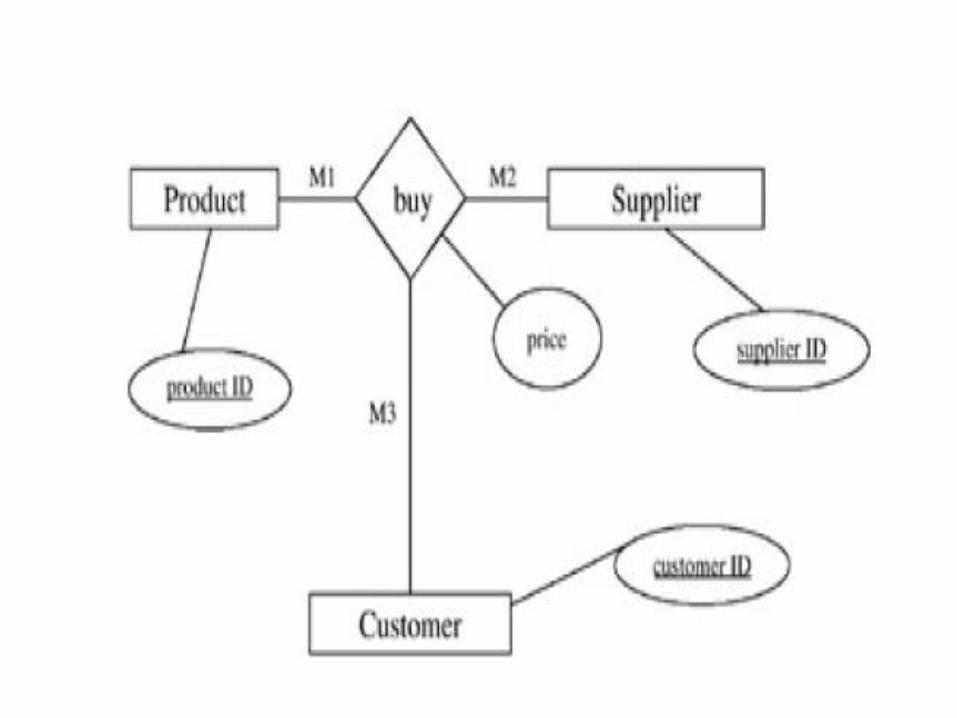
Step 7: Map n-ary (higher than binary) relationships.

• M6 — For n -ary relationships — For each n –ary relationship, create a new table. In the table, include all attributes of the relationship. Then include all keys of connected entities as foreign keys and make the concatenation of the foreign keys the primary key of

the new table.

Page 34: Mapping ER Diagram to a Relational Database · Mapping ER Diagram to a Relational Database Step 1:-Map the strong entities in the ER diagram. M1 — For strong entities — create
Page 35: Mapping ER Diagram to a Relational Database · Mapping ER Diagram to a Relational Database Step 1:-Map the strong entities in the ER diagram. M1 — For strong entities — create
Page 36: Mapping ER Diagram to a Relational Database · Mapping ER Diagram to a Relational Database Step 1:-Map the strong entities in the ER diagram. M1 — For strong entities — create

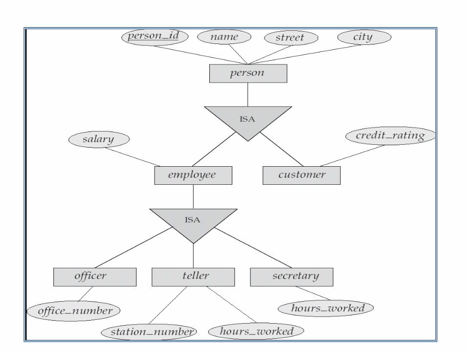
Step 8: Map generalizations/specializations.

• M7 — For each generalization/specialization entity situation, create one table for the generalization entity and create one table for each specialization entity. Put the attributes for each entity in the corresponding table. Add the primary key of the generalization entity into the specialization entity. The primary key of the specialization will be the same primary key as the generalization

Page 37: Mapping ER Diagram to a Relational Database · Mapping ER Diagram to a Relational Database Step 1:-Map the strong entities in the ER diagram. M1 — For strong entities — create