1 Introduction The Kinetis family of devices are pre-manufactured with Kinetis bootloader in either the ROM or flash memory of the device, and can boot into the Kinetis bootloader application. A PC host or master can connect to the Kinetis bootloader device via USB-HID or UART interface, and uses the bootloader’s command protocol interface in programming the image on the Kinetis device. The latest version of the Manufacturing tool (MfgTool) application supports the Kinetis bootloader and can be used in factory production environment much the same way as with other MfgTool supported devices. The MfgTool application can detect the presence of the Kinetis bootloader device connected to PC and invokes “blhost.exe” to program the image on the target Kinetis device. The Kinetis bootloader and blhost utility are documented in great detail at www.nxp.com/ KBOOT. This document provides a user’s guide on how to use MfgTool for the Kinetis device manufacturing. 2 Directory structure Freescale Semiconductor Document Number: KBLMFGTOOLUG User's Guide Rev. 0, 04/2016 Manufacturing Tool v.2.0.0 (MfgTool2) for Kinetis Bootloader User's Guide © 2016 Freescale Semiconductor, Inc. Contents 1 Introduction................................................................1 2 Directory structure..................................................... 1 3 Initialization files....................................................... 3 4 GUI elements.............................. .............................. 4 5 Troubleshooting guide..................... ....................... 11 6 Revision history.......................... ............................ 14

Welcome message from author
This document is posted to help you gain knowledge. Please leave a comment to let me know what you think about it! Share it to your friends and learn new things together.
Transcript

1 IntroductionThe Kinetis family of devices are pre-manufactured withKinetis bootloader in either the ROM or flash memory of thedevice, and can boot into the Kinetis bootloader application. APC host or master can connect to the Kinetis bootloader devicevia USB-HID or UART interface, and uses the bootloader’scommand protocol interface in programming the image on theKinetis device.
The latest version of the Manufacturing tool (MfgTool)application supports the Kinetis bootloader and can be used infactory production environment much the same way as withother MfgTool supported devices. The MfgTool applicationcan detect the presence of the Kinetis bootloader deviceconnected to PC and invokes “blhost.exe” to program theimage on the target Kinetis device. The Kinetis bootloader andblhost utility are documented in great detail at www.nxp.com/KBOOT. This document provides a user’s guide on how touse MfgTool for the Kinetis device manufacturing.
2 Directory structure
Freescale Semiconductor Document Number: KBLMFGTOOLUG
User's Guide Rev. 0, 04/2016
Manufacturing Tool v.2.0.0(MfgTool2) for Kinetis BootloaderUser's Guide
© 2016 Freescale Semiconductor, Inc.
Contents
1 Introduction................................................................1
2 Directory structure.....................................................1
3 Initialization files.......................................................3
4 GUI elements.............................. .............................. 4
5 Troubleshooting guide..................... ....................... 11
6 Revision history.......................... ............................ 14
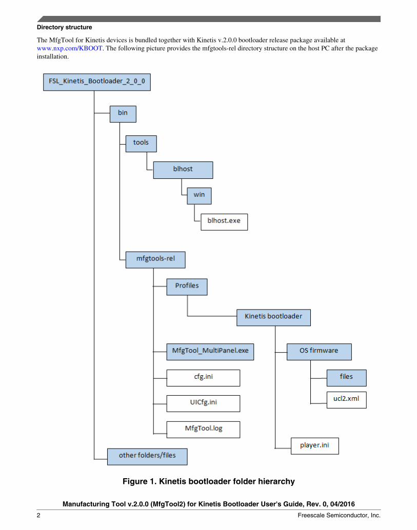
The MfgTool for Kinetis devices is bundled together with Kinetis v.2.0.0 bootloader release package available atwww.nxp.com/KBOOT. The following picture provides the mfgtools-rel directory structure on the host PC after the packageinstallation.
Figure 1. Kinetis bootloader folder hierarchy
Directory structure
Manufacturing Tool v.2.0.0 (MfgTool2) for Kinetis Bootloader User's Guide, Rev. 0, 04/2016
2 Freescale Semiconductor, Inc.
In the package, the mfgtools-rel folder appears under the bin/tools folder along with blhost folder.
The blhost.exe appears under the blhost/win folder and the MfgTool executable 'MfgTool2.exe' appears under the mfgtools-relfolder.
The Profiles folder contains the profile for the Kinetis bootloader device that includes an ‘OS Firmware' folder and player.inifile.
The files folder under ‘OS Firmware’ folder may include along with custom files the application image to download on thedevice.
The ucl2.xml file under the ‘OS Firmware’ folder is the main XML that MfgTool processes. It contains the flow of themanufacturing process for the device, which includes identification parameters for the device and blhost commandssequenced to query the device and program the image. The example ucl2.xml is delivered with USB device identificationparameters to identify the Kinetis bootloader device connected to the PC host and a set of blhost commands required forupdating the image on the device. The ucl2.xml file can be customized to suit custom setup or manufacturing process flow.The folder contain several example xml files for customer's reference
The player.ini in the ‘Kinetis bootloader’ profile folder contain configurable parameters for the manufacturing toolapplication.
The cfg.ini and UICfg.ini files provide customizable parameters for the look and feel of the tool’s GUI.
The MfgTool.log text file is a useful tool to debug failures reported on MfgTool UI. The MfgTool logs the entire commandline string it used to invoke blhost, and also collects the output response text the blhost puts out on stdout into theMfgTool.log file. The log file is the first place to look at for troubleshooting. The troubleshooting guide section at the end ofthis document discusses more on the information the tool logs into MfgTool.log text file.
3 Initialization filesThis section focuses on the parameters controlling the appearance of MfgTool User Interface and other behavior that can becontrolled via the initialization files with .ini extension. The initialization files can be edited using any text editor.
• The UICfg.ini file is used to configure the number of ports that indicates number of devices that can be simultaneouslyattached to multiple USB ports of the host PC and can be programmed simultaneously. Mfgtool presents one panel foreach port on its GUI.
The format of the UICfg.ini file is as indicated below:
[UICfg]PortMgrDlg=1
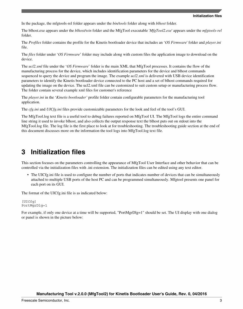
For example, if only one device at a time will be supported, "PortMgrDlg=1" should be set. The UI display with one dialogor panel is shown in the picture below:
Initialization files
Manufacturing Tool v.2.0.0 (MfgTool2) for Kinetis Bootloader User's Guide, Rev. 0, 04/2016
Freescale Semiconductor, Inc. 3
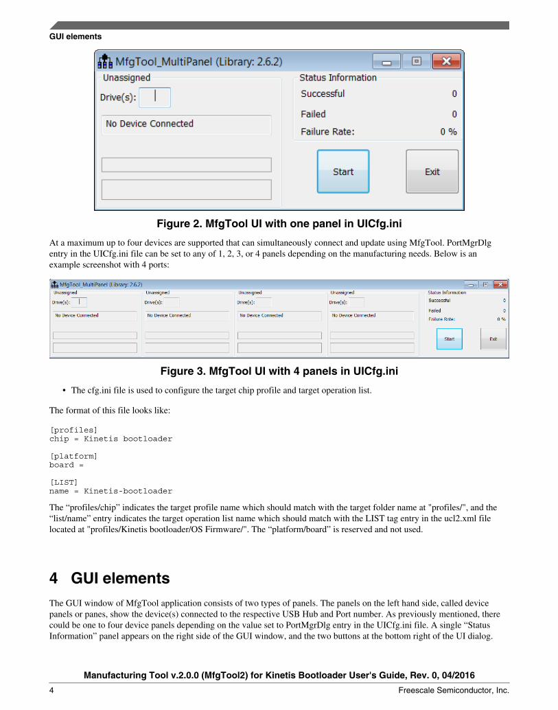
Figure 2. MfgTool UI with one panel in UICfg.ini
At a maximum up to four devices are supported that can simultaneously connect and update using MfgTool. PortMgrDlgentry in the UICfg.ini file can be set to any of 1, 2, 3, or 4 panels depending on the manufacturing needs. Below is anexample screenshot with 4 ports:
Figure 3. MfgTool UI with 4 panels in UICfg.ini
• The cfg.ini file is used to configure the target chip profile and target operation list.
The format of this file looks like:
[profiles]chip = Kinetis bootloader
[platform]board =
[LIST]name = Kinetis-bootloader
The “profiles/chip” indicates the target profile name which should match with the target folder name at "profiles/", and the“list/name” entry indicates the target operation list name which should match with the LIST tag entry in the ucl2.xml filelocated at "profiles/Kinetis bootloader/OS Firmware/". The “platform/board” is reserved and not used.
4 GUI elementsThe GUI window of MfgTool application consists of two types of panels. The panels on the left hand side, called devicepanels or panes, show the device(s) connected to the respective USB Hub and Port number. As previously mentioned, therecould be one to four device panels depending on the value set to PortMgrDlg entry in the UICfg.ini file. A single “StatusInformation” panel appears on the right side of the GUI window, and the two buttons at the bottom right of the UI dialog.
GUI elements
Manufacturing Tool v.2.0.0 (MfgTool2) for Kinetis Bootloader User's Guide, Rev. 0, 04/2016
4 Freescale Semiconductor, Inc.

Figure 4. UI showing one device connected to PC Host in the idle state
4.1 Device panel
The device panel shows the PC hub and port numbers at the top of the pane to which the Kinetis bootloader device isconnected.
The UI element “Drive(s)” is not applicable for Kinetis bootloader devices.
The next UI element shows the type of device connected in the idle state. Kinetis bootloader device connected in USB-HIDmode the display shows ‘HID-compliant device’, and when connected in UART mode the text shows the respective virtualCOM port number along with the description of the device as appears in the Windows® OS device manager. Whilemanufacturing (non-idle state), the same element shows the command in execution. When MfgTool is complete, thecommand sequences succesfully, the element can be made to display text such as ‘Done’, which will be discussed later in thisdocument. When the manufacturing process is halted by the user using the "Stop" button, the text reverts back to the devicedescription. The example screen capture below shows four Kinetis devices connected to four USB ports in HID and CDCmodes in the idle state.
Figure 5. UI showing 4 Kinetis devices connected to the PC Host in the idle state
The last two UI elements of the device pane are progress bars that show progress while manufacturing. The first elementshows the progress of current blhost command being executed, and the second element shows the overall progress tocomplete execution of all the commands listed in the ucl2.xml file. The progress bar can appear in three different colors. Blueindicates that the manufacturing is in process, green indicates that manufacturing completed successfully, and red indicatesan error has occurred. The error information will be logged into Mfgtool.log file for decoding purposes.
4.2 Status information panel
The Status Information panel have three data points, Successful Operations shows number of Kinetis bootloader devicessuccessfully manufactured, Failed Operations shows number of devices failed and Failure Rate show the percentage failure.
The image below shows manufacturing in progress.
GUI elements
Manufacturing Tool v.2.0.0 (MfgTool2) for Kinetis Bootloader User's Guide, Rev. 0, 04/2016
Freescale Semiconductor, Inc. 5
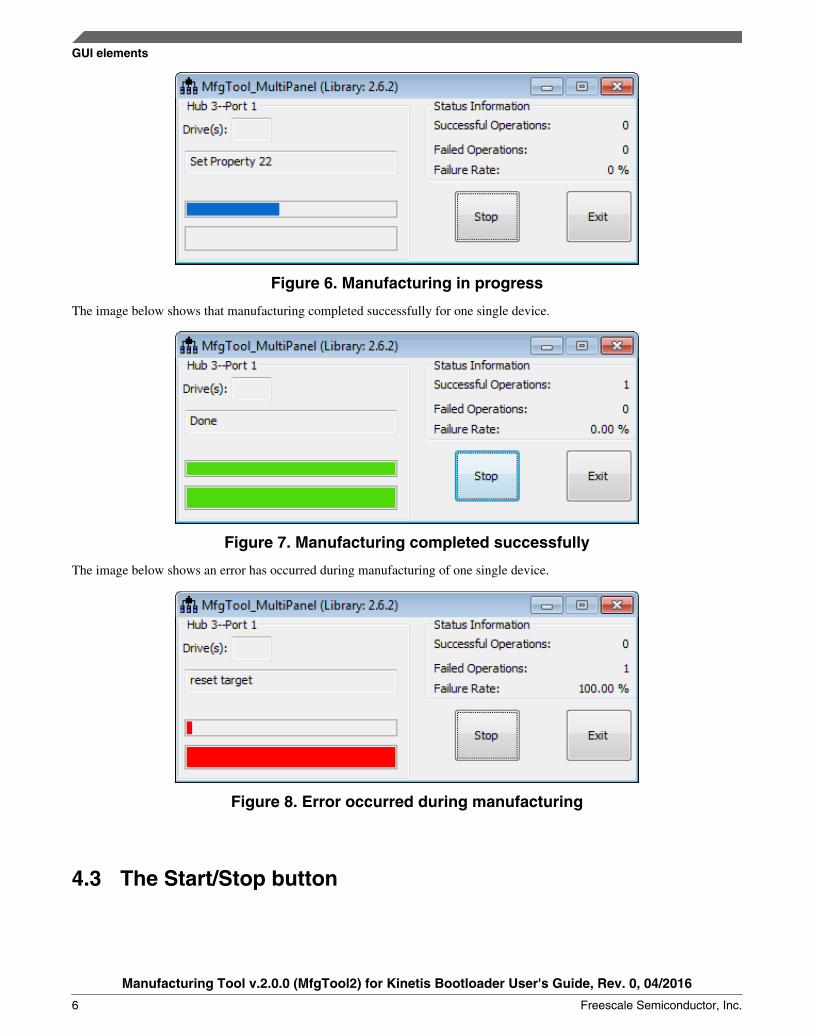
Figure 6. Manufacturing in progress
The image below shows that manufacturing completed successfully for one single device.
Figure 7. Manufacturing completed successfully
The image below shows an error has occurred during manufacturing of one single device.
Figure 8. Error occurred during manufacturing
4.3 The Start/Stop button
GUI elements
Manufacturing Tool v.2.0.0 (MfgTool2) for Kinetis Bootloader User's Guide, Rev. 0, 04/2016
6 Freescale Semiconductor, Inc.
The "Start" button for the UI element appears in the idle state when the manufacturing process has either stopped or has notyet begun. To begin the manufacturing process, the "Start" button should be pressed. After pressing the "Start" button, thetext on the button changes to “Stop” and acts like a stop button. The Stop button should be pressed after completion of themanufacturing process, or pressed at any time to halt the process. The "Stop" button should be used carefully, in order to notstop while command is in execution. Otherwise, an incomplete update may result in an unresponsive device.
4.3.1 Exit button
The "Exit" button can be pressed to close the MfgTool application. The "Exit" button can only work in the idle state, or when"Start" button is active. The "Exit" button does not work while the device manufacturing is in progress. An error messagedialog will appear if the "Exit" button is pressed while manufacturing. The "Stop" button should be pressed first to stop themanufacturing process, which activates the "Start" button. Then, the "Exit" button can be used to close the window andshutdown the MfgTool application.
4.4 Firmware update process
The chapter and subsections below describe the process of device manufacturing using the Freescale MfgTool application forthe Kinetis bootloader devices.
4.4.1 Kinetis bootloader device identification
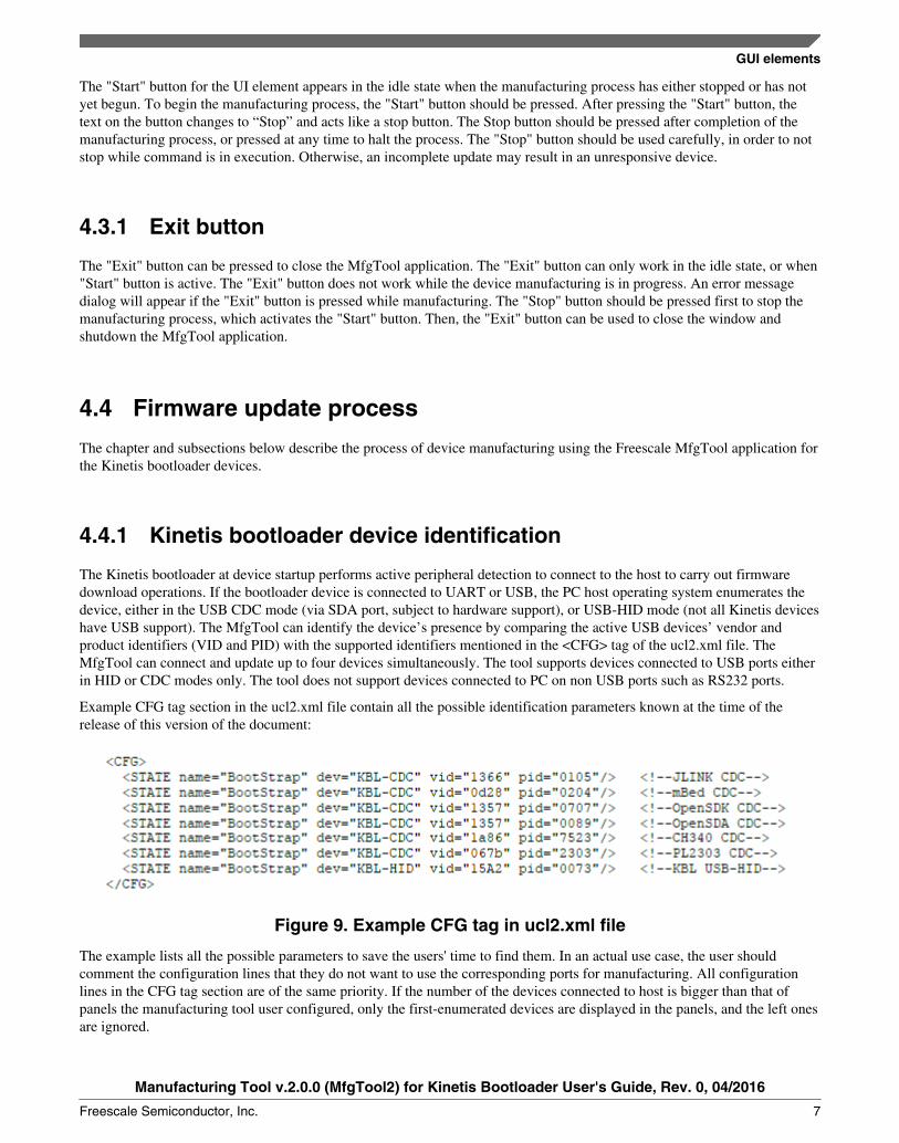
The Kinetis bootloader at device startup performs active peripheral detection to connect to the host to carry out firmwaredownload operations. If the bootloader device is connected to UART or USB, the PC host operating system enumerates thedevice, either in the USB CDC mode (via SDA port, subject to hardware support), or USB-HID mode (not all Kinetis deviceshave USB support). The MfgTool can identify the device’s presence by comparing the active USB devices’ vendor andproduct identifiers (VID and PID) with the supported identifiers mentioned in the <CFG> tag of the ucl2.xml file. TheMfgTool can connect and update up to four devices simultaneously. The tool supports devices connected to USB ports eitherin HID or CDC modes only. The tool does not support devices connected to PC on non USB ports such as RS232 ports.
Example CFG tag section in the ucl2.xml file contain all the possible identification parameters known at the time of therelease of this version of the document:
Figure 9. Example CFG tag in ucl2.xml file
The example lists all the possible parameters to save the users' time to find them. In an actual use case, the user shouldcomment the configuration lines that they do not want to use the corresponding ports for manufacturing. All configurationlines in the CFG tag section are of the same priority. If the number of the devices connected to host is bigger than that ofpanels the manufacturing tool user configured, only the first-enumerated devices are displayed in the panels, and the left onesare ignored.
GUI elements
Manufacturing Tool v.2.0.0 (MfgTool2) for Kinetis Bootloader User's Guide, Rev. 0, 04/2016
Freescale Semiconductor, Inc. 7

The below image shows Windows OS device manager showing one Kinetis bootloader device connected in USB-HID mode,and two devices connected in USB CDC mode, accessible via serial COM ports 3 and 6.
Figure 10. Windows OS Device Manager showing Kinetis devices connected in USB-HIDand UART modes
The image below shows the corresponding 4-panel MfgTool user interface picture for the above connected devices showingone device connected in HID mode, two devices connected in CDC mode, and the last panel displaying as "No deviceconnected".
GUI elements
Manufacturing Tool v.2.0.0 (MfgTool2) for Kinetis Bootloader User's Guide, Rev. 0, 04/2016
8 Freescale Semiconductor, Inc.
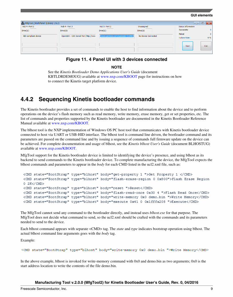
Figure 11. 4 Panel UI with 3 devices connected
NOTESee the Kinetis Bootloader Demo Applications User's Guide (documentKBTLDRDEMOUG) available at www.nxp.com/KBOOT page for instructions on howto connect the Kinetis target platform device.
4.4.2 Sequencing Kinetis bootloader commands
The Kinetis bootloader provides a set of commands to enable the host to find information about the device and to performoperations on the device’s flash memory such as read memory, write memory, erase memory, get or set properties, etc. Thelist of commands and properties supported by the Kinetis bootloader are documented in the Kinetis Bootloader ReferenceManual available at www.nxp.com/KBOOT.
The blhost tool is the NXP implementation of Windows OS PC host tool that communicates with Kinetis bootloader deviceconnected to host via UART or USB-HID interface. The blhost tool is command line driven, the bootloader command and itsparameters are passed on the command line and by issuing a sequence of commands full firmware update on the device canbe achieved. For complete documentation and usage of blhost, see the Kinetis blhost User's Guide (document BLHOSTUG)available at www.nxp.com/KBOOT.
MfgTool support for the Kinetis bootloader device is limited to identifying the device’s presence, and using blhost as itsbackend to send commands to the Kinetis bootloader device. To complete manufacturing the device, the MfgTool expects theblhost commands and parameters to appear in the body for each CMD listed in the ucl2.xml file, such as:
The MfgTool cannot send any command to the bootloader directly, and instead uses blhost.exe for that purpose. TheMfgTool does not decide what command to send, so the ucl2.xml should be crafted with the commands and its parametersneeded to send to the device.
Each blhost command appears with separate <CMD> tag. The state and type indicates bootstrap operation using blhost. Theactual blhost command line arguments goes with the body tag.
Example:
In the above example, blhost is invoked for write-memory command with 0x0 and demo.bin as two arguments; 0x0 is thestart address location to write the contents of the file demo.bin.
GUI elements
Manufacturing Tool v.2.0.0 (MfgTool2) for Kinetis Bootloader User's Guide, Rev. 0, 04/2016
Freescale Semiconductor, Inc. 9
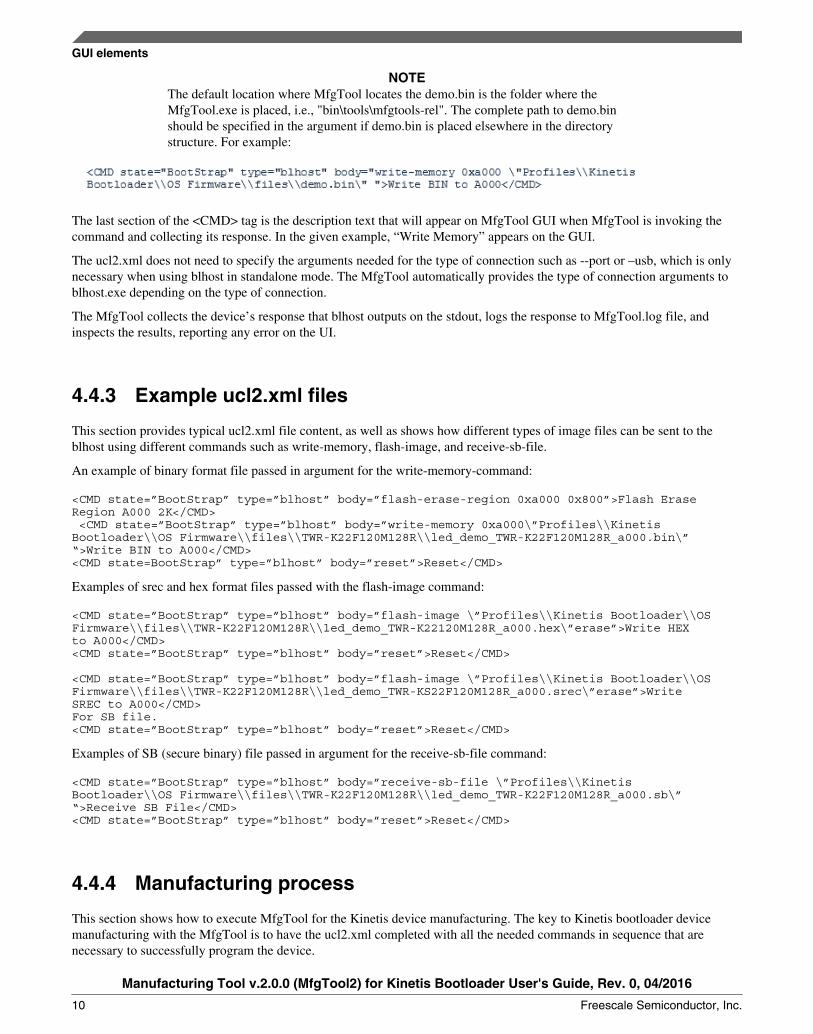
NOTEThe default location where MfgTool locates the demo.bin is the folder where theMfgTool.exe is placed, i.e., "bin\tools\mfgtools-rel". The complete path to demo.binshould be specified in the argument if demo.bin is placed elsewhere in the directorystructure. For example:
The last section of the <CMD> tag is the description text that will appear on MfgTool GUI when MfgTool is invoking thecommand and collecting its response. In the given example, “Write Memory” appears on the GUI.
The ucl2.xml does not need to specify the arguments needed for the type of connection such as --port or –usb, which is onlynecessary when using blhost in standalone mode. The MfgTool automatically provides the type of connection arguments toblhost.exe depending on the type of connection.
The MfgTool collects the device’s response that blhost outputs on the stdout, logs the response to MfgTool.log file, andinspects the results, reporting any error on the UI.
4.4.3 Example ucl2.xml files
This section provides typical ucl2.xml file content, as well as shows how different types of image files can be sent to theblhost using different commands such as write-memory, flash-image, and receive-sb-file.
An example of binary format file passed in argument for the write-memory-command:
<CMD state=”BootStrap” type=”blhost” body=”flash-erase-region 0xa000 0x800”>Flash Erase Region A000 2K</CMD> <CMD state=”BootStrap” type=”blhost” body=”write-memory 0xa000\”Profiles\\KinetisBootloader\\OS Firmware\\files\\TWR-K22F120M128R\\led_demo_TWR-K22F120M128R_a000.bin\”“>Write BIN to A000</CMD> <CMD state=BootStrap” type=”blhost” body=”reset”>Reset</CMD>
Examples of srec and hex format files passed with the flash-image command:
<CMD state=”BootStrap” type=”blhost” body=”flash-image \”Profiles\\Kinetis Bootloader\\OS Firmware\\files\\TWR-K22F120M128R\\led_demo_TWR-K22120M128R_a000.hex\”erase”>Write HEX to A000</CMD><CMD state=”BootStrap” type=”blhost” body=”reset”>Reset</CMD>
<CMD state=”BootStrap” type=”blhost” body=”flash-image \”Profiles\\Kinetis Bootloader\\OS Firmware\\files\\TWR-K22F120M128R\\led_demo_TWR-KS22F120M128R_a000.srec\”erase”>Write SREC to A000</CMD>For SB file.<CMD state=”BootStrap” type=”blhost” body=”reset”>Reset</CMD>
Examples of SB (secure binary) file passed in argument for the receive-sb-file command:
<CMD state=”BootStrap” type=”blhost” body=”receive-sb-file \”Profiles\\KinetisBootloader\\OS Firmware\\files\\TWR-K22F120M128R\\led_demo_TWR-K22F120M128R_a000.sb\”“>Receive SB File</CMD><CMD state=”BootStrap” type=”blhost” body=”reset”>Reset</CMD>
4.4.4 Manufacturing process
This section shows how to execute MfgTool for the Kinetis device manufacturing. The key to Kinetis bootloader devicemanufacturing with the MfgTool is to have the ucl2.xml completed with all the needed commands in sequence that arenecessary to successfully program the device.
GUI elements
Manufacturing Tool v.2.0.0 (MfgTool2) for Kinetis Bootloader User's Guide, Rev. 0, 04/2016
10 Freescale Semiconductor, Inc.

The typical setup at manufacturing is depicted in the image below with four devices connected to four USB ports to the PCrunning MfgTool application.
Figure 12. Typical setup at manufacturing
The manufacturing process begins once the operator launches the MfgTool application and selects the Start button.
The MfgTool provides UI to show device update progress for each device connected to the PC. As mentioned earlier, UI alsoshows the description text as appears in ucl2.xml for the command that is in execution. To indicate end of programming for adevice, a dummy command can be placed at the end of ucl2.xml file with the text “Done” to conveniently identifycompletion of the update so that the operator or the user can know when to switch to the new blank device. Example dummycommand to indicate completion of the update can look like:
<CMD state="BootStrap" type="blhost" body="Update Complete!">Done</CMD>
The MfgTool is in a continuous update mode until it is stopped by the user by pressing the "Stop" button. No user interactionis necessary on the UI once the "Start" button is pressed, except for pulling off the manufactured device once complete andconnecting to the new blank device.
5 Troubleshooting guide
Troubleshooting guide
Manufacturing Tool v.2.0.0 (MfgTool2) for Kinetis Bootloader User's Guide, Rev. 0, 04/2016
Freescale Semiconductor, Inc. 11
The MfgTool logs the command and response from the device into the MfgTool.log. When the device returns a failure codefor a command or timed out or for any other reason, the MfgTool UI indicates the occurrence of the failure. The cause can bediagnosed by inspecting the MfgTool.log file. To open the MfgTool.log file, it is recommended to stop the MfgTool usingthe "Stop" button, as MfgTool continuously logs information to the file.
Example:
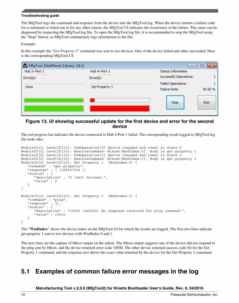
In this example the “Get Property 1” command was sent to two devices. One of the device failed and other succeeded. Hereis the corresponding MfgTool UI:
Figure 13. UI showing successful update for the first device and error for the seconddevice
The red progress bar indicates the device connected to Hub 4-Port 1 failed. The corresponding result logged to MfgTool.logfile looks like:
ModuleID[2] LevelID[10]: CmdOperation[0] device changed and reset to state 0ModuleID[2] LevelID[10]: ExecuteCommand--Blhost[WndIndex:0], Body is get-property 1 ModuleID[2] LevelID[10]: CmdOperation[1] device changed and reset to state 0ModuleID[2] LevelID[10]: ExecuteCommand--Blhost[WndIndex:1], Body is get-property 1 ModuleID[2] LevelID[10]: Get Property 1 [WndIndex:0] { "command" : "get-property", "response" : [ 1258357504 ], "status" : { "description" : "0 (0x0) Success.", "value" : 0 }}
ModuleID[2] LevelID[10]: Get Property 1 [WndIndex:1] { "command" : "ping", "response" : [], "status" : { "description" : "10500 (0x2904) No response received for ping command.", "value" : 10500 }}
The “WndIndex” shows the device index on the MfgTool UI for which the results are logged. The first two lines indicateget-property 1 sent to two devices with WndIndex 0 and 1.
The next lines are the capture of blhost output on the stdout. The blhost output suggests one of the device did not respond tothe ping sent by blhost, and the device returned error code 10500. The other device returned success code (0) for the GetProperty 1 command, and the response text shows the exact value returned by the device for the Get Property 1 command.
5.1 Examples of common failure error messages in the log
Troubleshooting guide
Manufacturing Tool v.2.0.0 (MfgTool2) for Kinetis Bootloader User's Guide, Rev. 0, 04/2016
12 Freescale Semiconductor, Inc.

5.1.1 Cannot find ..\blhost\win\blhost.exe
The failure reports for missing blhost.exe in the folder blhost\win\. The tool searches for blhost.exe in the bin\tools\blhost\win folder. Make sure it is available in the correct folder.
5.1.2 No response received for the ping command
{ "command" : "flash-erase-all-unsecure", "response" : [], "status" : { "description" : "10000 (0x2710) kStatus_UnknownCommand", "value" : 10000 }}
There could be several reasons for such an error. Here are some troubleshooting steps:• See the reference manual for the device to ensure the device is supported by the Kinetis bootloader.• Check whether the device is powered up.• The device may boot off the image on the flash and not the kinetis bootloader image from ROM or flash. Erase the
flash memory and try again to allow the device to boot in the Kinetis bootloader mode.• Direct boot feature might be enabled. Erase the flash and try again to boot into Kinetis bootloader.
5.1.3 UnknownCommand
{"command" : "flash-erase-all-unsecure", "response" : [], "status" : { "description" : "10000 (0x2710) kStatus_UnknownCommand", "value" : 10000 }}
The blhost.exe can execute all Kinetis bootloader commands. However, the command itself may not be supported by thetarget Kinetis bootloader device. See the ROM Bootloader/Flashloader chapter of the device reference manual to checkwhether the command is supported.
5.1.4 Command disallowed when security is enabled
{ "command" : "flash-erase-all", "response" : [], "status" : { "description" : "10001 (0x2711) Command disallowed when security is enabled.", "value" : 10001 }}
The device is in secure state and cannot be programmed. To program a secured device the unlock command should be addedto the ucl2.xml file.
Troubleshooting guide
Manufacturing Tool v.2.0.0 (MfgTool2) for Kinetis Bootloader User's Guide, Rev. 0, 04/2016
Freescale Semiconductor, Inc. 13
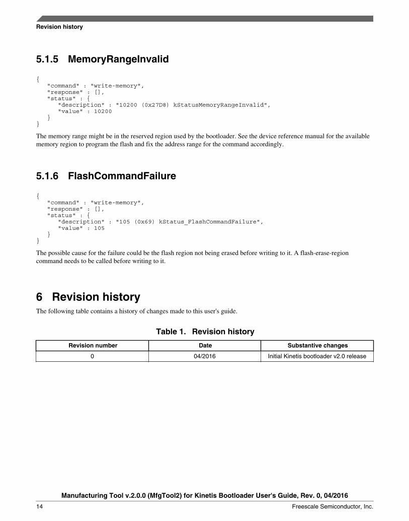
5.1.5 MemoryRangeInvalid
{ "command" : "write-memory", "response" : [], "status" : { "description" : "10200 (0x27D8) kStatusMemoryRangeInvalid", "value" : 10200 }}
The memory range might be in the reserved region used by the bootloader. See the device reference manual for the availablememory region to program the flash and fix the address range for the command accordingly.
5.1.6 FlashCommandFailure
{ "command" : "write-memory", "response" : [], "status" : { "description" : "105 (0x69) kStatus_FlashCommandFailure", "value" : 105 }}
The possible cause for the failure could be the flash region not being erased before writing to it. A flash-erase-regioncommand needs to be called before writing to it.
6 Revision historyThe following table contains a history of changes made to this user's guide.
Table 1. Revision history
Revision number Date Substantive changes
0 04/2016 Initial Kinetis bootloader v2.0 release
Revision history
Manufacturing Tool v.2.0.0 (MfgTool2) for Kinetis Bootloader User's Guide, Rev. 0, 04/2016
14 Freescale Semiconductor, Inc.

Document Number: KBLMFGTOOLUGRev. 004/2016
Information in this document is provided solely to enable system and software
implementers to use Freescale products. There are no express or implied copyright
licenses granted hereunder to design or fabricate any integrated circuits based on the
information in this document.
Freescale reserves the right to make changes without further notice to any products
herein. Freescale makes no warranty, representation, or guarantee regarding the
suitability of its products for any particular purpose, nor does Freescale assume any
liability arising out of the application or use of any product or circuit, and specifically
disclaims any and all liability, including without limitation consequential or incidental
damages. “Typical” parameters that may be provided in Freescale data sheets and/or
specifications can and do vary in different applications, and actual performance may
vary over time. All operating parameters, including “typicals,” must be validated for
each customer application by customer’s technical experts. Freescale does not convey
any license under its patent rights nor the rights of others. Freescale sells products
pursuant to standard terms and conditions of sale, which can be found at the following
address: nxp.com/SalesTermsandConditions.
How to Reach Us:Home Page: nxp.com
Web Support: nxp.com/support
Freescale, the Freescale logo, and Kinetis are trademarks of Freescale
Semiconductor, Inc., Reg. U.S. Pat. & Tm. Off. All other product or service names are
the property of their respective owners. All rights reserved.
© 2016 Freescale Semiconductor, Inc.
Related Documents