MANUFACTURING & TESTING OF COMPOSITE HYBRID LEAF SPRIGN FOR AUTOMOTIVE APPLICATIONS by Himal Agrawal A Thesis Submitted to the Faculty of Purdue University In Partial Fulfillment of the Requirements for the degree of Master of Science in Aeronautics and Astronautics School of Aeronautics & Astronautics West Lafayette, Indiana August 2019

Welcome message from author
This document is posted to help you gain knowledge. Please leave a comment to let me know what you think about it! Share it to your friends and learn new things together.
Transcript
MANUFACTURING & TESTING OF COMPOSITE HYBRID LEAF
SPRIGN FOR AUTOMOTIVE APPLICATIONS by
Himal Agrawal
A Thesis
Submitted to the Faculty of Purdue University
In Partial Fulfillment of the Requirements for the degree of
Master of Science in Aeronautics and Astronautics
School of Aeronautics & Astronautics
West Lafayette, Indiana
August 2019
2
THE PURDUE UNIVERSITY GRADUATE SCHOOL
STATEMENT OF COMMITTEE APPROVAL
Dr. R. Byron Pipes, Chair
Department of Aeronautics and Astronautics
Dr. Wenbin Yu
Department of Aeronautics and Astronautics
Dr. Johnathan Goodsell
Department of Aeronautics and Astronautics
Approved by:
Dr. Wayne Chen
Head of the Graduate Program

3
Dedicated to my parents Rajesh and Ruchi Agrawal
4
ACKNOWLEDGMENTS
I am deeply indebted to Dr. R. Byron Pipes for giving me an opportunity to work with him
at Purdue University. He has been a constant source of motivation and always helped me push my
boundaries to achieve a goal. Not only I learned the technical knowledge related to composites
from him but also to deal with problems pragmatically with a never-ending smile on the face. His
confidence in my abilities helped me solve problems which otherwise I could have not solved
alone. It won’t be an exaggeration to say that experience of working with him would be an integral
part of success in my life ahead. I would also like to thank Mike Bogdanor for the financial support
during my masters. Working with him always inspired me to expand my horizon and learn more
about different topics. I will be grateful for all the technical knowledge learnt from him.
I would also express my sincere gratitude to Sergey Kravchenko, Tim Tsai and Miguel
Ramirez for all the support and help during my masters. Their help was instrumental in initial
stages of the project. I also want to acknowledge the help of Bill Applegate whose practical
manufacturing experience and knowledge helped me build and test things. I am also thankful to
Dr. Ronald Sterkenburg, Tyler Futch and Garam Kim for helping me operate different machines
in the lab. Also, to Orzuri Rique Garaizar, Akshay Jacob Thomas, Sushrut Karmarkar, Ben Denos,
Drew Sommer, Becky Cutting, Jorge Ramirez and Eduardo Barocio, I thank them for moral
support and being supportive in my research endeavors. I would like to thank Purdue University
for a great research atmosphere and intellectually amazing peers I met.
The work would have not been possible without the support from my parents who always
encouraged and supported me to follow my dreams and have a constant source of motivation and
guidance in life.
5
TABLE OF CONTENTS
LIST OF TABLES .......................................................................................................................... 7
LIST OF FIGURES ........................................................................................................................ 8
ABSTRACT .................................................................................................................................. 11
1. INTRODUCTION ................................................................................................................. 12
Overview of composites ................................................................................................... 12
Overview of leaf spring .................................................................................................... 15
Previous work in composite leaf springs .......................................................................... 18
2. THEORY BEHIND LEAF SPRING DESIGN ..................................................................... 29
Design elements for leaf spring ........................................................................................ 29
2.1.1 Spring Eyes ................................................................................................................ 29
2.1.2 Leaf Ends ................................................................................................................... 30
2.1.3 Center Bolt ................................................................................................................. 31
2.1.4 Center Clamp ............................................................................................................. 32
2.1.5 Shackles ..................................................................................................................... 33
2.1.6 Variable rate leaf spring ............................................................................................. 33
Design considerations and calculations for leaf spring ..................................................... 34
3. MANUFACTRING OF LEAF SPRING ............................................................................... 49
Fixture Manufacturing ...................................................................................................... 49
Fixture FEM Simulation and Laser Scanning of leaf spring ............................................ 52
Tool machining and part trimming ................................................................................... 53
Problems while manufacturing leaf spring ....................................................................... 57
4. RESULTS .............................................................................................................................. 60
Results for mechanical properties of glass fiber laminates ............................................... 60
Experimental setup ............................................................................................................ 63
Static and fatigue testing of metal and hybrid leaf spring ................................................ 65
Fatigue testing of composite beams with Aspect Ratio 10 ............................................... 76
Fatigue testing of composite beams with Aspect Ratio 30 ............................................... 82
5. SUMMARY AND CONCLUSION ...................................................................................... 82
Summary ........................................................................................................................... 91

6
Conclusion ........................................................................................................................ 92
REFRENCES ................................................................................................................................ 93
7
LIST OF TABLES
Table 2.1 - Stiffening factor for different loading conditions ....................................................... 37
Table 3.1 – Glass Fiber prepreg properties ................................................................................... 49
Table 4.1 - Characterized mechanical properties of glass fiber laminates ................................... 60
Table 4.2 - Unclamped stiffness of metal and hybrid leaf spring ................................................. 67
Table 4.3 - Clamped stiffness of metal and hybrid leaf spring ..................................................... 68
Table 4.4 - Stress and strains adjacent to clamping region ........................................................... 74
Table 4.5 - Max load, corresponding disp. and stiffness for flexure samples, Aspect Ratio 10 ... 77
Table 4.6 - Results for failure load, displacement and sample stiffness, Aspect Ratio 30 ........... 83
Table 4.7 - Initial and final stiffness after cyclic loading comparison for different specimens ... 90
8
LIST OF FIGURES
Figure 1.1 - Molecular structure for thermoplastic and thermoset resins [3] ............................... 13
Figure 1.2 - Process explaining making of laminates using prepregs ........................................... 14
Figure 1.3 - Large size autoclave .................................................................................................. 14
Figure 1.4 - Process of making part using compression molding [5] ........................................... 15
Figure 1.5 - Leaf spring assembly in automotive application [6] ................................................. 16
Figure 1.6 - Shackle attachment at one end of the leaf spring [7] ................................................ 16
Figure 1.7 - Overslung vs underslung leaf spring [8] ................................................................... 17
Figure 1.8 - Mono leaf spring made using carbon and glass fiber with bolted end fasteners [10] 19
Figure 1.9 - Testing of spring bolted end fasteners for longitudinal forces [10] .......................... 20
Figure 1.10 - Constant area leaf with hyperbolic profile for compression molding [11] ............. 21
Figure 1.11 – Steel prototype spring [12] ..................................................................................... 22
Figure 1.12 - Fatigue and stiffness testing jig for composite leaf spring [12] .............................. 22
Figure 1.13 - Optimization of cross sectional design using genetic algorithm [13] ..................... 23
Figure 1.14 - Double tapered composite mono leaf spring [16] ................................................... 24
Figure 1.15 - Process for making charge and compression molding of leaf spring [17] .............. 24
Figure 1.16 - Multicavity tool for resin transfer molding of leaf springs [19] ............................. 26
Figure 1.17 - Transverse composite leaf spring for Volvo XC90 [20] ......................................... 26
Figure 1.18 - Use of rolled prepregs for leaf spring compression molding [21] .......................... 27
Figure 1.19 - Compression molding press [21] ............................................................................ 27
Figure 1.20 - Attachment of leaf spring using metal fasteners [21] ............................................. 28
Figure 2.1 - Different ends (eyes) for the leaf spring assembly. Adapted from [22] .................... 29
Figure 2.2 - Different types of leaf ends. Adapted from [22] ....................................................... 31
Figure 2.3 - U bolt assembly used for clamping leaf spring to axle ............................................. 32
Figure 2.4 - Side view of multistage variable rate leaf spring. Adapted from [22] ...................... 33
Figure 2.5 - Different views for uniform strength beam. Adapted from [22] ............................... 34
Figure 2.6 - Original and deflected geometry of complete and half leaf spring. Adapted from [22]
....................................................................................................................................................... 38
Figure 2.7 - Uniform overhang and thickness spring. Adapted from [22] ................................... 40
Figure 2.8 - Stresses in leafs with and without assembly stresses. Adapted from [22] ................ 41
9
Figure 2.9 - Effect of assembly stresses on short and long leaves. Adapted from [22] ................ 42
Figure 2.10 - Windup of symmetric spring. Adapted from [22] ................................................... 46
Figure 2.11 - Vertical displacement and rotation coupling in unsymmetrical spring. Adapted
from [22] ....................................................................................................................................... 47
Figure 3.1 - Isometric CAD view for designed fixtures ............................................................... 50
Figure 3.2 - Cutting of side plate using waterjet process .............................................................. 50
Figure 3.3 - Isometric view of side trolley of fixture .................................................................... 51
Figure 3.4 - Fixture and leaf spring assembly ............................................................................... 51
Figure 3.5 - Stress distribution in the fixture due to maximum loading ....................................... 52
Figure 3.6 – Laser scanning the geometry of leaf spring .............................................................. 53
Figure 3.7 - Machining of the tooling board ................................................................................. 53
Figure 3.8 - Machined tool for layup ............................................................................................ 54
Figure 3.9 - Trimming of the composite leaf ................................................................................ 55
Figure 3.10 - Assembled hybrid leaf spring .................................................................................. 56
Figure 3.11 - Cracking of composite 3rd leaf ................................................................................ 57
Figure 3.12 - Observed damage due to curved surface and high bolt torque ............................... 57
Figure 3.13 - Microscopy of cracked surface ............................................................................... 58
Figure 3.14 - Use of silicone dams to avoid resin spill ................................................................. 59
Figure 3.15 - Leaf spring assembly after replacing cracked third leaf ......................................... 59
Figure 4.1 - Stress vs Strain for loading in 1 direction ................................................................. 61
Figure 4.2 - Stress vs Strain for loading in 2 direction ................................................................. 61
Figure 4.3 - Stress vs Strain for shear loading .............................................................................. 62
Figure 4.4 - Failure of specimens from loading in 1 direction ..................................................... 62
Figure 4.5 - Failure of specimens from loading in 2 direction ..................................................... 63
Figure 4.6 - Failure of specimens from shear loading .................................................................. 63
Figure 4.7 - Experimental test setup ............................................................................................. 64
Figure 4.8 - Deflection of spring in unclamped condition ............................................................ 65
Figure 4.9 - Loading of composite spring in unclamped and clamped condition ......................... 66
Figure 4.10 - Load vs Displacement of metal and composite leaf spring in unclamped condition
....................................................................................................................................................... 67
Figure 4.11 - Load vs Displacement of metal and composite leaf spring in clamped condition .. 68
10
Figure 4.12 - Stiffness vs cycles for metal spring, 5.5 in max displacement ................................ 69
Figure 4.13 - Stiffness vs cycles for hybrid spring, 6.5 in max displacement .............................. 70
Figure 4.14 - Metal spring being loaded using spacer block and plate to enhance displacements71
Figure 4.15 - Stiffness vs cycles for metal spring, extreme loading ............................................. 71
Figure 4.16 - Load vs cycles for metal spring, extreme loading ................................................... 72
Figure 4.17 - Stiffness vs cycles for hybrid spring, extreme loading ........................................... 73
Figure 4.18 - Load vs cycles for hybrid spring, extreme loading ................................................. 73
Figure 4.19 - Location of strain gauges on the main leaf ............................................................. 74
Figure 4.20 - 3-point flexure fixture for composite specimens .................................................... 76
Figure 4.21 - Failure of samples quasi-statically, Aspect Ratio 10 .............................................. 77
Figure 4.22 - Side view of samples failed quasi-statically, Aspect Ratio 10 ................................ 78
Figure 4.23 - Bottom view of samples failed quasi-statically, Aspect Ratio 10 ........................... 78
Figure 4.24 - Stiffness vs cycles for specimen 1, Aspect Ratio 10 ............................................... 79
Figure 4.25 - Stiffness vs cycles for specimen 2, Aspect Ratio 10 ............................................... 79
Figure 4.26 - Stiffness vs cycles for specimen 3, Aspect Ratio 10 ............................................... 80
Figure 4.27 - Stiffness vs cycles for specimen 4, Aspect Ratio 10 ............................................... 80
Figure 4.28 - Side view for failure of specimens in cyclic loading, Aspect Ratio 10 .................. 81
Figure 4.29 - Top view for failure of specimens in cyclic loading, Aspect Ratio 10 ................... 81
Figure 4.30 - Load vs Displacement for quasi-static testing, Aspect Ratio 30 ............................. 82
Figure 4.31 - Prismatic connection to ensure vertical motion of the jaw ..................................... 84
Figure 4.32 - Slotted pin used for holding samples ...................................................................... 84
Figure 4.33 - Stiffness vs cycles for sample 1, Aspect Ratio 30 .................................................. 85
Figure 4.34 - Stiffness vs cycles for sample 2, Aspect Ratio 30 .................................................. 85
Figure 4.35 - Stiffness vs cycles for sample 3, Aspect Ratio 30 .................................................. 86
Figure 4.36 - Stiffness vs cycles for sample 4, Aspect Ratio 30 .................................................. 86
Figure 4.37 - Bottom view of specimens after cyclic loading, Aspect Ratio 30 .......................... 87
Figure 4.38 - Load vs cycles for sample 1, Aspect Ratio 30 ........................................................ 88
Figure 4.39 - Load vs cycles for sample 2, Aspect Ratio 30 ........................................................ 88
Figure 4.40 - Load vs cycles for sample 3, Aspect Ratio 30 ........................................................ 89
Figure 4.41 - Load vs cycles for sample 4, Aspect Ratio 30 ........................................................ 89
11
ABSTRACT
Author: Agrawal, Himal. MSAAE Institution: Purdue University Degree Received: August 2019 Title: Manufacturing and Testing of Composite Hybrid Leaf Spring for Automotive
Applications. Committee Chair: Dr. R. Byron Pipes
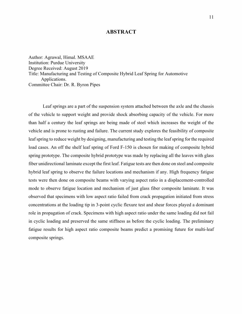
Leaf springs are a part of the suspension system attached between the axle and the chassis
of the vehicle to support weight and provide shock absorbing capacity of the vehicle. For more
than half a century the leaf springs are being made of steel which increases the weight of the
vehicle and is prone to rusting and failure. The current study explores the feasibility of composite
leaf spring to reduce weight by designing, manufacturing and testing the leaf spring for the required
load cases. An off the shelf leaf spring of Ford F-150 is chosen for making of composite hybrid
spring prototype. The composite hybrid prototype was made by replacing all the leaves with glass
fiber unidirectional laminate except the first leaf. Fatigue tests are then done on steel and composite
hybrid leaf spring to observe the failure locations and mechanism if any. High frequency fatigue
tests were then done on composite beams with varying aspect ratio in a displacement-controlled
mode to observe fatigue location and mechanism of just glass fiber composite laminate. It was
observed that specimens with low aspect ratio failed from crack propagation initiated from stress
concentrations at the loading tip in 3-point cyclic flexure test and shear forces played a dominant
role in propagation of crack. Specimens with high aspect ratio under the same loading did not fail
in cyclic loading and preserved the same stiffness as before the cyclic loading. The preliminary
fatigue results for high aspect ratio composite beams predict a promising future for multi-leaf
composite springs.
12
1. INTRODUCTION
Overview of composites
The increase in regulations against pollution and the race to achieve higher efficiency has forced
the industries to focus on alternate materials which are lighter and can be easily processed.
Composites fit in the solution to the problem. Composites are a combination of two or more
different materials whose combination produce completely different properties compared to
individual material properties[1]. The materials in composites can be distinguished using
appropriate methods as they do not blend into each other. Composites occur naturally and are also
made in the industries. Examples of naturally occurring composites include wood which is a
combination of long cellulose fibers and lignin which is a weaker substance and holds the fibers
together. Cotton also contains cellulose but lacks lignin and hence there is nothing to bind the
fibers which makes it much weaker to wood for structural applications. Another example of
composite is the bone in human body which is made of hydroxyapatite and collagen which is a
soft and flexible material and binds hydroxyapatite together. All these examples have one thing in
common which is that there is a binder, also called matrix, which binds the fibers or fragments of
other material which is also called the reinforcement. Different types of fibers are available in the
market and the most commonly used fibers are glass and carbon. There are different polymers
available for binding the fibers and the polymers are broadly categorized into two categories which
are thermosets and thermoplastics. The main difference between thermosets and thermoplastics is
that thermoplastics can be melted back to conform to the original shape whereas thermosets once
formed cannot be conformed back into original shape by applying temperature[2]. Thermoplastic
polymers flow with the increase of temperature and solidify when cooled. The polymer chains
flow to restructure themselves but no chemical reaction takes place between the strands of the
chain whereas with the thermoset polymers there is chemical reaction which takes place between
different chains which cannot be reserved and hence the chains are entangled and cannot retain
their original shape with the increase in temperature.
13
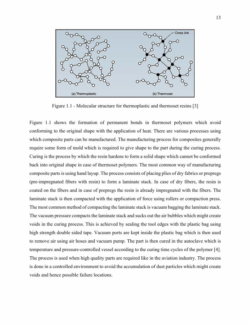
Figure 1.1 - Molecular structure for thermoplastic and thermoset resins [3]
Figure 1.1 shows the formation of permanent bonds in thermoset polymers which avoid
conforming to the original shape with the application of heat. There are various processes using
which composite parts can be manufactured. The manufacturing process for composites generally
require some form of mold which is required to give shape to the part during the curing process.
Curing is the process by which the resin hardens to form a solid shape which cannot be conformed
back into original shape in case of thermoset polymers. The most common way of manufacturing
composite parts is using hand layup. The process consists of placing plies of dry fabrics or prepregs
(pre-impregnated fibers with resin) to form a laminate stack. In case of dry fibers, the resin is
coated on the fibers and in case of prepregs the resin is already impregnated with the fibers. The
laminate stack is then compacted with the application of force using rollers or compaction press.
The most common method of compacting the laminate stack is vacuum bagging the laminate stack.
The vacuum pressure compacts the laminate stack and sucks out the air bubbles which might create
voids in the curing process. This is achieved by sealing the tool edges with the plastic bag using
high strength double sided tape. Vacuum ports are kept inside the plastic bag which is then used
to remove air using air hoses and vacuum pump. The part is then cured in the autoclave which is
temperature and pressure-controlled vessel according to the curing time cycles of the polymer [4].
The process is used when high quality parts are required like in the aviation industry. The process
is done in a controlled environment to avoid the accumulation of dust particles which might create
voids and hence possible failure locations.
14
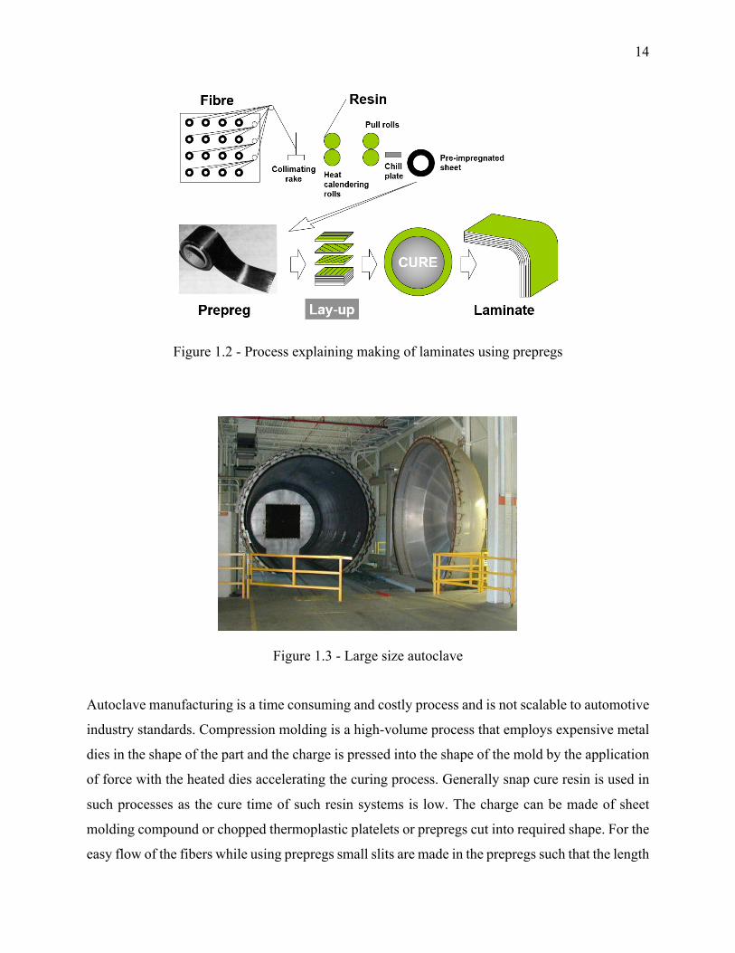
Figure 1.2 - Process explaining making of laminates using prepregs
Figure 1.3 - Large size autoclave
Autoclave manufacturing is a time consuming and costly process and is not scalable to automotive
industry standards. Compression molding is a high-volume process that employs expensive metal
dies in the shape of the part and the charge is pressed into the shape of the mold by the application
of force with the heated dies accelerating the curing process. Generally snap cure resin is used in
such processes as the cure time of such resin systems is low. The charge can be made of sheet
molding compound or chopped thermoplastic platelets or prepregs cut into required shape. For the
easy flow of the fibers while using prepregs small slits are made in the prepregs such that the length
15
of the fibers reduces or the long fibers will not flow in small dimensions of the tool. The typical
process for SMC’s includes cutting them in required shape to form the charge and the charge is
heated with the mold to the point where the viscosity of the charge is minimum and the mold is
then pressed at the required temperature. The feasibility of compression molding is being explored
on a vast scale in aviation as well as automotive industry. Automakers are studying the feasibility
to make exterior car body panels using carbon fiber SMC’s to take advantage of the high stiffness
to weight ratio of composites. New snap cure resins are being developed to prevent micro-cracking,
UV, impact and moisture resistance with required surface quality demands.
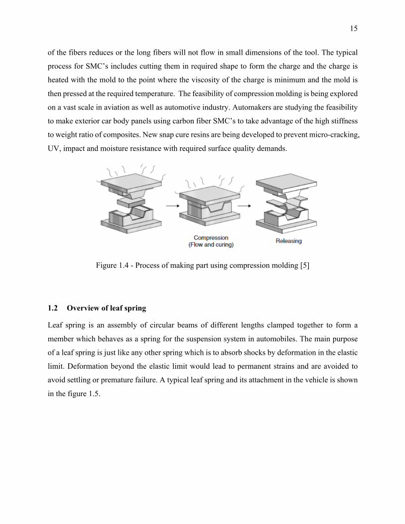
Figure 1.4 - Process of making part using compression molding [5]
Overview of leaf spring
Leaf spring is an assembly of circular beams of different lengths clamped together to form a
member which behaves as a spring for the suspension system in automobiles. The main purpose
of a leaf spring is just like any other spring which is to absorb shocks by deformation in the elastic
limit. Deformation beyond the elastic limit would lead to permanent strains and are avoided to
avoid settling or premature failure. A typical leaf spring and its attachment in the vehicle is shown
in the figure 1.5.
16
Figure 1.5 - Leaf spring assembly in automotive application [6]
The leaf spring can also be used as a structural member or attaching linkage unlike coil springs or
torsion springs. This advantage is utilized while designing leaf spring to avoid extra linkage
weights. The spring rate is defined as change in load per unit deflection and is different throughout
the spring. The spring rate is also different in uninstalled and installed conditions due to clamping
effects on the chassis which reduce the active length of the spring and thus increasing the clamped
stiffness of the spring. One end of the spring is pinned with the chassis and at the other end shackle
is attached to the vehicle. A shackle is a link with one end hinged to the chassis and the other to
the leaf spring. Shackle eliminates the direct attachment of both the spring ends to the chassis
which would lead to an indeterminate system.
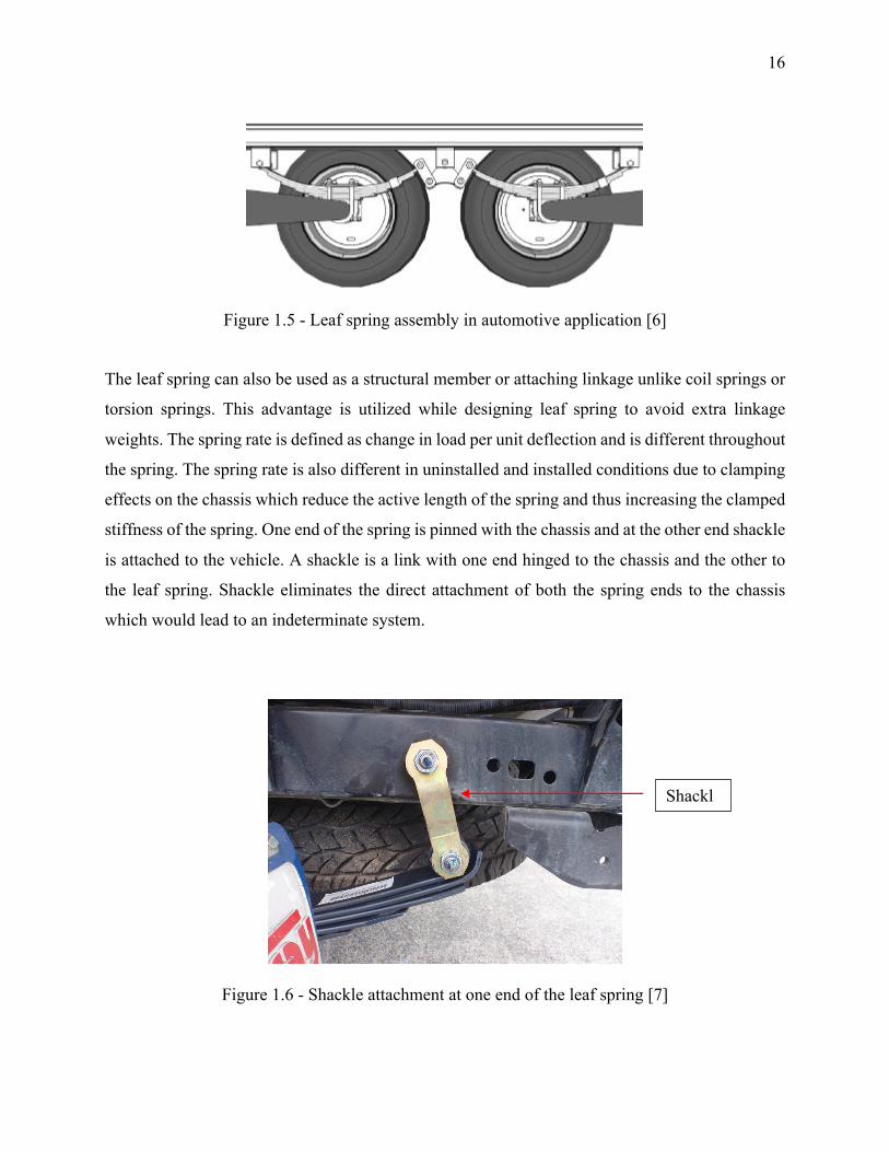
Figure 1.6 - Shackle attachment at one end of the leaf spring [7]
Shackl
e
17
The hinging of one end of the spring to the chassis and the other to the shackle allows the
movement of leaf spring due to deflection from the load. The spring stiffness also varies as a
function of shackle angle and hence the stiffness is variable when the leaf spring is attached in the
automobile with the shackles. A big consideration while designing the suspension system is the
ride comfort. A soft ride would require low stiffness of the suspension system and hence higher
deflection of the spring. This can have a negative effect on many factors which are listed below:
1. A softer spring would lead to higher deflection and hence would be heavy due to increased
length.
2. The softer spring would require larger ride clearance (distance between chassis and the
spring) due to higher defection.
3. The standing deflection of the vehicle due to its own weight would be much larger for a
more flexible spring.
The standing deflection of the vehicle also affects braking, stability and cornering and hence due
to space and design considerations it is not possible to make the suspension system as soft as
possible. Ride clearance plays a major role in deciding the static deflection of the vehicle.
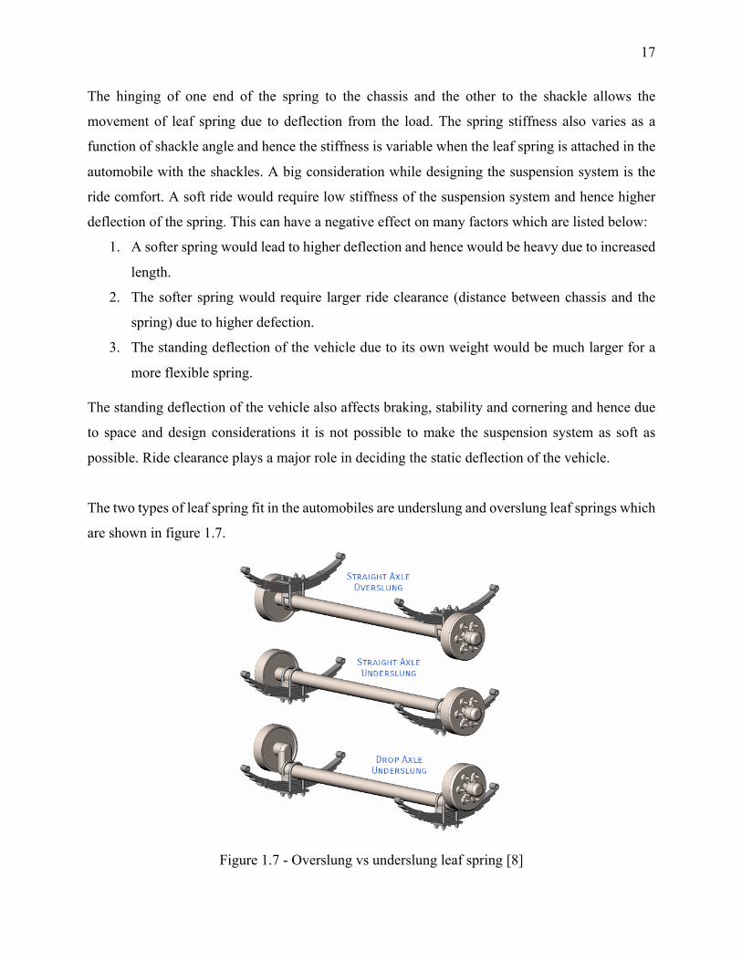
The two types of leaf spring fit in the automobiles are underslung and overslung leaf springs which
are shown in figure 1.7.
Figure 1.7 - Overslung vs underslung leaf spring [8]
18
Figure 1.7 shows the difference between the overslung and the underslung springs. Overslung
springs are supported at the top of the axle and the underslung are supported at the bottom of the
axle using a U bolt. The low position of the spring in case of underslung spring lowers down the
center of gravity of vehicle and helps in vertical stability but must be mounted low for stability
from horizontal forces and this reduces the ground clearance of the vehicle. Another disadvantage
of underslung leaf spring is that the clearance between the chassis and the axle is reduced which
might lead to metal-metal contact between the chassis and the axle.
Previous work in composite leaf springs
The potential of saving upto 400 kg of weight from heavy commercial vehicle composite spring
have been an interesting study topic for automotive industries. With the advancement of
technology, composite springs are steadily finding its way for the suspension system for rail
transportation. Composites being one-fifth the weight with almost same structural strength offer
enhanced ride properties due to decreased unsprung weight and enhanced lateral stiffness.
Extensive studies were done by the automobile industries in the late 1970s for checking the
feasibility of composite leaf springs. The following studies done by various industries over a period
of 10 years around 1970s is summarized below and details have been added to list out the gaps in
the studies performed.
Bruce E. Kirkham et. al. [9] developed corvette liteflex composite spring. The target was to obtain
half a million cycles without failure with less than 5% of the load drop which was successful. A
random production composite spring even passed 10 million cycles to failure. Composite spring
was also tested at low and high temperatures and after exposure to various chemicals like
transmission oil, brake fluid, gasoline, water and many more. Stress relaxation with the number of
cycles, noise isolation and vehicle handling were also studied. The spring was fit above the
differential axle and near the exhaust and was subject to high temperatures from exhaust radiation
as well as heating of differential. No problems occurred during the test which constituted of
800,000 durability kilometers and 4.5 million fleet test kilometers.
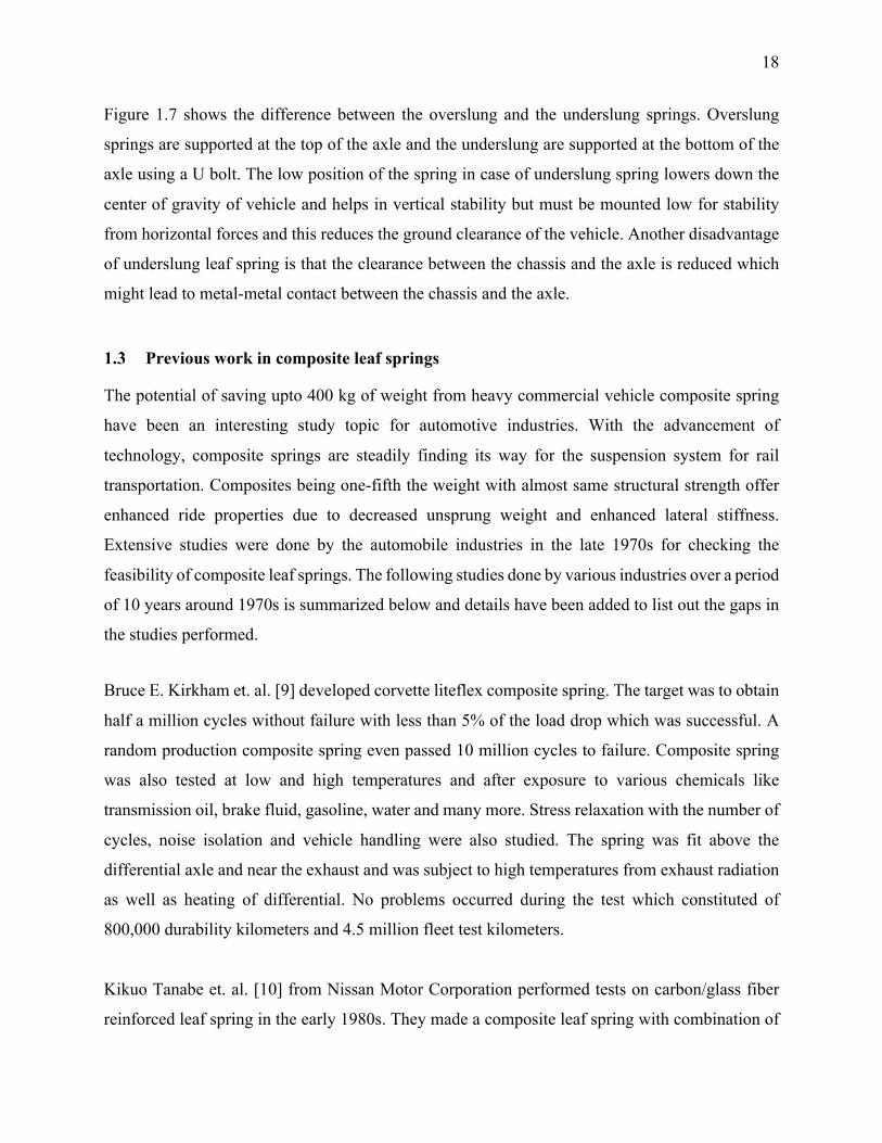
Kikuo Tanabe et. al. [10] from Nissan Motor Corporation performed tests on carbon/glass fiber
reinforced leaf spring in the early 1980s. They made a composite leaf spring with combination of
19
glass and carbon fiber to increase spring stiffness. The figure 1.8 shows the schematic of the spring
design.
Figure 1.8 - Mono leaf spring made using carbon and glass fiber with bolted end fasteners [10]
The spring was made with constant width but varying thickness along the length and steel eyes
related to the composite beam using bolts. The beam was used with a combination of glass and
carbon fiber with woven glass fiber and the ends and the center and unidirectional carbon fiber
between the ends and the center to provide enhanced stiffness. The geometry of the mono leaf
spring was made such that it is equally stiffer to the steel spring. It was found that the endurance
of the composite spring was much higher than the steel spring and the static rate of the spring was
equal to the steel spring with a 76% weight reduction. The lateral rate was however found to be
77% of the steel spring but the decrease in lateral rate on lateral shake and ride handling was
observed to be not significant. Both composite and steel spring had the same handling and lateral
shake characteristics. The decrease in friction forces for composite leaf spring gives better ride
handling on smooth roads. The composite leaf spring was also tested for stone chippings by testing
the vehicle on rough road for 2000 kms. The damage observed was insignificant and had almost
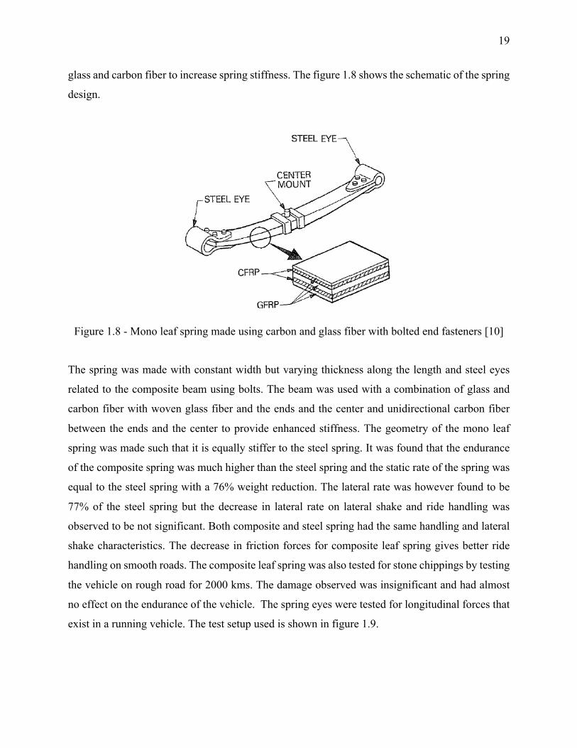
no effect on the endurance of the vehicle. The spring eyes were tested for longitudinal forces that
exist in a running vehicle. The test setup used is shown in figure 1.9.
20
Figure 1.9 - Testing of spring bolted end fasteners for longitudinal forces [10]
The test vehicle considered had longitudinal forces for the spring around 10,000 N in the vehicle
and the eye was loaded to 50,000 N without observing significant damage. The test was then
stopped due to high observed factor of safety.
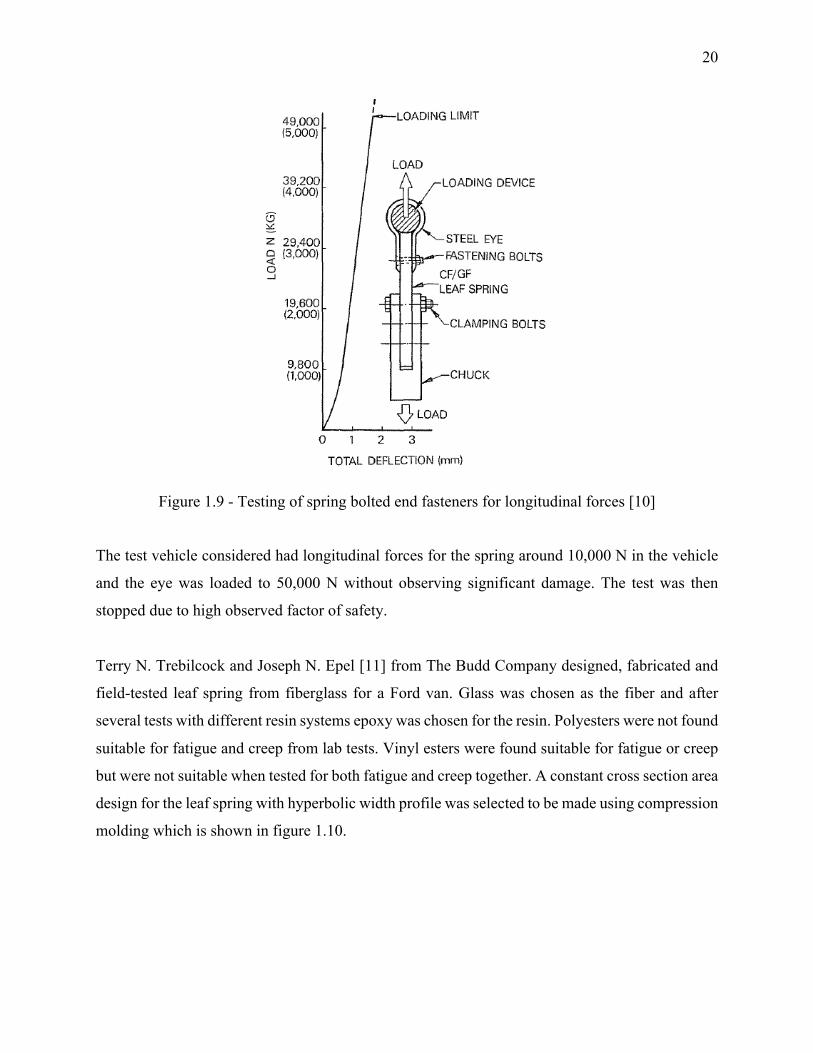
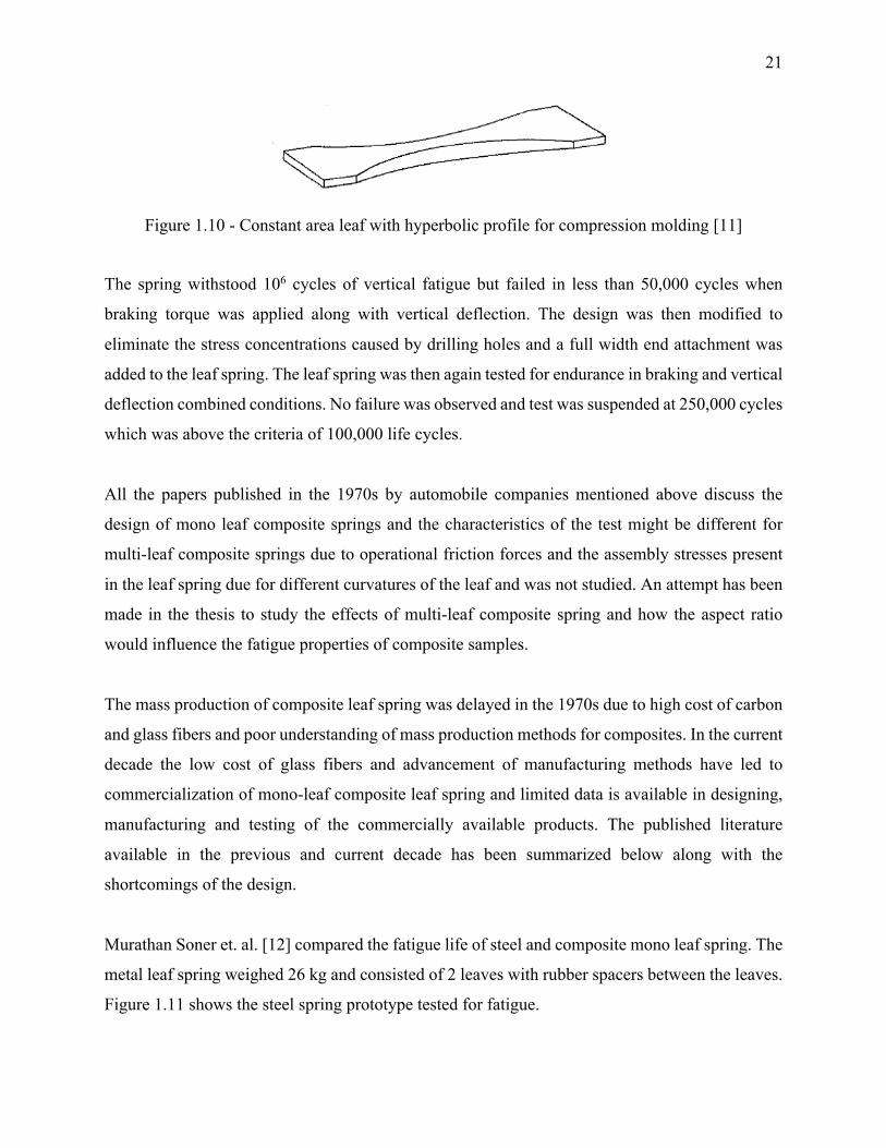
Terry N. Trebilcock and Joseph N. Epel [11] from The Budd Company designed, fabricated and
field-tested leaf spring from fiberglass for a Ford van. Glass was chosen as the fiber and after
several tests with different resin systems epoxy was chosen for the resin. Polyesters were not found
suitable for fatigue and creep from lab tests. Vinyl esters were found suitable for fatigue or creep
but were not suitable when tested for both fatigue and creep together. A constant cross section area
design for the leaf spring with hyperbolic width profile was selected to be made using compression
molding which is shown in figure 1.10.
21
Figure 1.10 - Constant area leaf with hyperbolic profile for compression molding [11]
The spring withstood 106 cycles of vertical fatigue but failed in less than 50,000 cycles when
braking torque was applied along with vertical deflection. The design was then modified to
eliminate the stress concentrations caused by drilling holes and a full width end attachment was
added to the leaf spring. The leaf spring was then again tested for endurance in braking and vertical
deflection combined conditions. No failure was observed and test was suspended at 250,000 cycles
which was above the criteria of 100,000 life cycles.
All the papers published in the 1970s by automobile companies mentioned above discuss the
design of mono leaf composite springs and the characteristics of the test might be different for
multi-leaf composite springs due to operational friction forces and the assembly stresses present
in the leaf spring due for different curvatures of the leaf and was not studied. An attempt has been
made in the thesis to study the effects of multi-leaf composite spring and how the aspect ratio
would influence the fatigue properties of composite samples.
The mass production of composite leaf spring was delayed in the 1970s due to high cost of carbon
and glass fibers and poor understanding of mass production methods for composites. In the current
decade the low cost of glass fibers and advancement of manufacturing methods have led to
commercialization of mono-leaf composite leaf spring and limited data is available in designing,
manufacturing and testing of the commercially available products. The published literature
available in the previous and current decade has been summarized below along with the
shortcomings of the design.
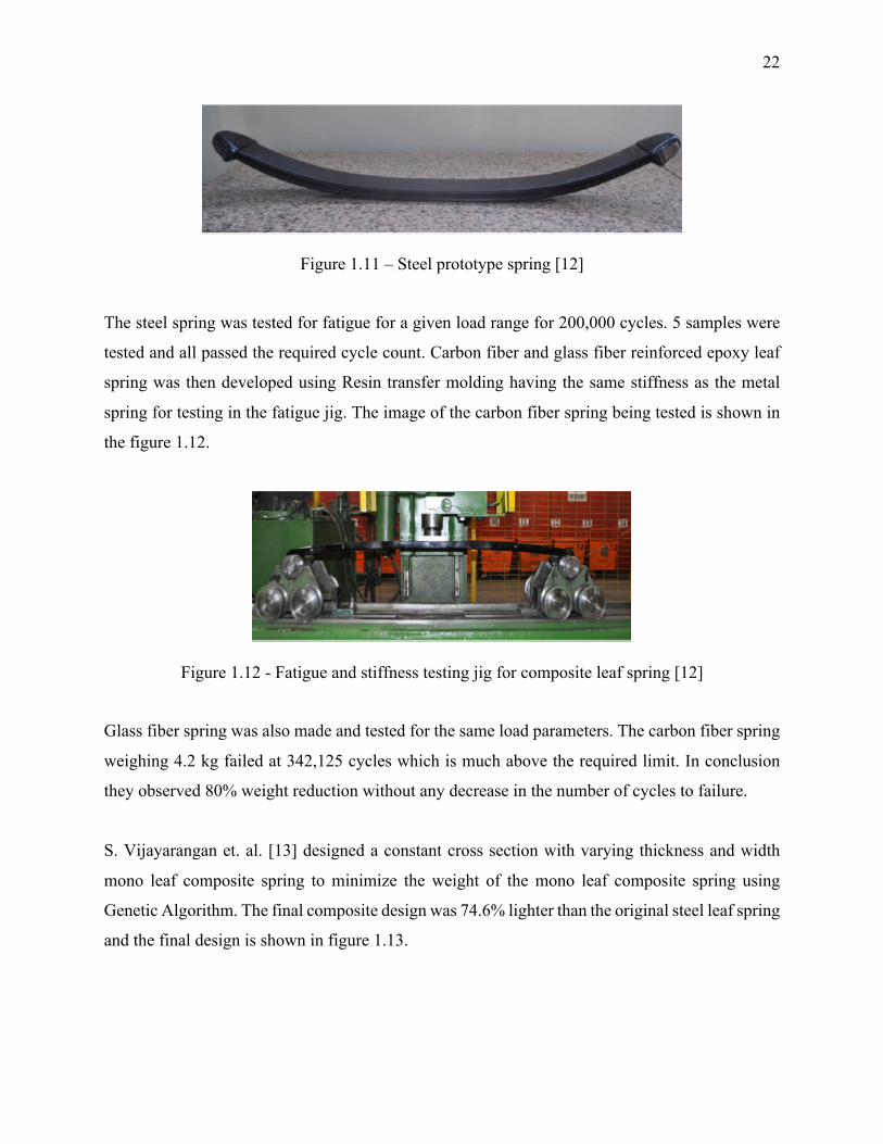
Murathan Soner et. al. [12] compared the fatigue life of steel and composite mono leaf spring. The
metal leaf spring weighed 26 kg and consisted of 2 leaves with rubber spacers between the leaves.
Figure 1.11 shows the steel spring prototype tested for fatigue.
22
Figure 1.11 – Steel prototype spring [12]
The steel spring was tested for fatigue for a given load range for 200,000 cycles. 5 samples were
tested and all passed the required cycle count. Carbon fiber and glass fiber reinforced epoxy leaf
spring was then developed using Resin transfer molding having the same stiffness as the metal
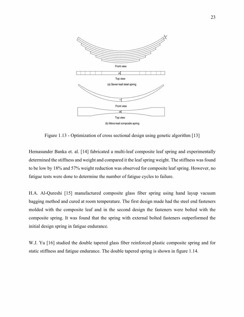
spring for testing in the fatigue jig. The image of the carbon fiber spring being tested is shown in
the figure 1.12.
Figure 1.12 - Fatigue and stiffness testing jig for composite leaf spring [12]
Glass fiber spring was also made and tested for the same load parameters. The carbon fiber spring
weighing 4.2 kg failed at 342,125 cycles which is much above the required limit. In conclusion
they observed 80% weight reduction without any decrease in the number of cycles to failure.
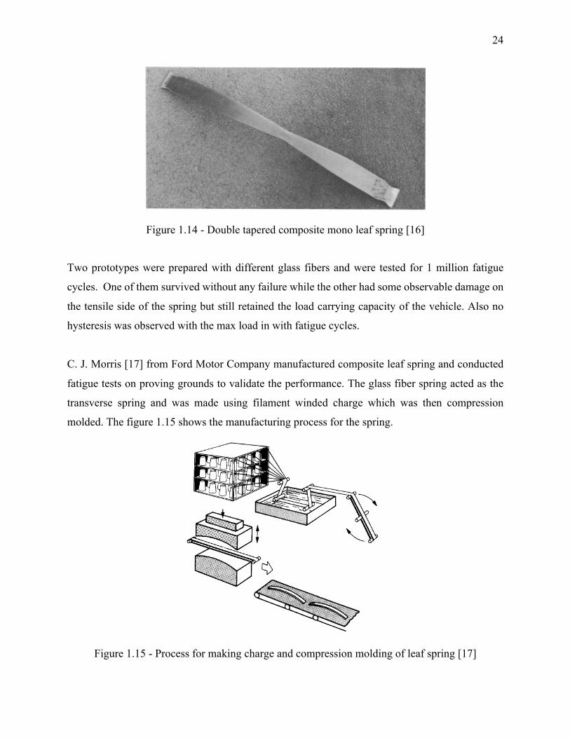
S. Vijayarangan et. al. [13] designed a constant cross section with varying thickness and width
mono leaf composite spring to minimize the weight of the mono leaf composite spring using
Genetic Algorithm. The final composite design was 74.6% lighter than the original steel leaf spring
and the final design is shown in figure 1.13.
23
Figure 1.13 - Optimization of cross sectional design using genetic algorithm [13]
Hemasunder Banka et. al. [14] fabricated a multi-leaf composite leaf spring and experimentally
determined the stiffness and weight and compared it the leaf spring weight. The stiffness was found
to be low by 18% and 57% weight reduction was observed for composite leaf spring. However, no
fatigue tests were done to determine the number of fatigue cycles to failure.
H.A. Al-Qureshi [15] manufactured composite glass fiber spring using hand layup vacuum
bagging method and cured at room temperature. The first design made had the steel end fasteners
molded with the composite leaf and in the second design the fasteners were bolted with the
composite spring. It was found that the spring with external bolted fasteners outperformed the
initial design spring in fatigue endurance.
W.J. Yu [16] studied the double tapered glass fiber reinforced plastic composite spring and for
static stiffness and fatigue endurance. The double tapered spring is shown in figure 1.14.
24
Figure 1.14 - Double tapered composite mono leaf spring [16]
Two prototypes were prepared with different glass fibers and were tested for 1 million fatigue
cycles. One of them survived without any failure while the other had some observable damage on
the tensile side of the spring but still retained the load carrying capacity of the vehicle. Also no
hysteresis was observed with the max load in with fatigue cycles.
C. J. Morris [17] from Ford Motor Company manufactured composite leaf spring and conducted
fatigue tests on proving grounds to validate the performance. The glass fiber spring acted as the
transverse spring and was made using filament winded charge which was then compression
molded. The figure 1.15 shows the manufacturing process for the spring.
Figure 1.15 - Process for making charge and compression molding of leaf spring [17]
25
The spring was tested in severe conditions at Dearbon proving grounds and no damage was
observed to the composite spring but the end effectors to the spring used for the attachment to the
chassis were damaged. They were then repaired and the test was continued and at the end no failure
was observed to the composite spring.
In the current decade a new method for high rate manufacturing of composite leaf spring is being
developed which involves the use of high-pressure resin transfer molding. Epoxy prepregs required
the use of autoclave for high quality product part which is required in the aerospace industry but
is time consuming and costly. New resin systems are formulated which are much lower in viscosity
than traditional epoxy and require a fraction of curing time as compared to traditional epoxies.
Loctile Max 2 resin developed by Henkel has a high modulus of 2800 MPa with a tensile strength
of 80 MPa and high toughness which translates to fatigue resistance. Benteler-SGL and Henkel
collaborated to use the newly developed resin Loctile Max 2 resin and reduced the curing time
from 30 mins to a mere of 8 mins with urethane. The resin system was characterized to find the
suitable injection temperature for viscosity as low as 30 mPas which leads to ultra-high injection
speed of 100g to 300g to resin flow per second. Max 3 resin system was then launched by Henkel
which also included a mold release agent with the formulation.
Snap cure resin systems are also being developed for medium to high volume production for
composites. They provide fast cure but long enough injection window for impregnating the fibers.
These chemicals are being developed by Momentive Specialty Chemicals based in Columbus,
Ohio. At such high injection speed preform binder is very important to avoid the distortion of
fibers with resin injection and negatively affect permeability of the preform. Low viscosity for
flow and high impregnation time were essential for ensuring good quality of the part. EPIKOTE
05475 resin with EPIKURE 05443 curing agent developed by the company cures the part within
5 mins at 120°C. Combination of EPIKOTE 05475 resin, EPIKURE 05500 curing agent with
Heloxy 112 internal mold release agent cures within 2 mins at 115°C [18].
Transverse leaf spring made of composite materials offer weight reduction as well as reduced
number of elements. For transverse leaf spring conventional steel elements such as antiroll bar
26
mounts and links, coil springs and two control arms are eliminated. The damping of composite
structures leads to reduced transmission of vibration noise to adjacent structures.
Benteler-SGL and IFC composites in Germany are two of the few companies who have
successfully commercialized the composite transverse leaf spring fitted in automobiles. Benteler-
SGL uses HP-RTM for composite leaf spring production where as IFC uses compression molding
of preforms for manufacturing leaf springs. Henkel’s Loctile max 2 resin is used in high pressure
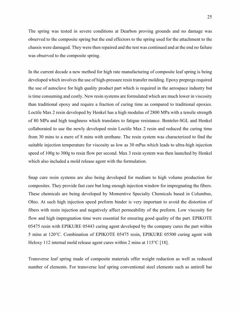
RTM and with multiple cavities production rate as high as 500,000 parts per year can be achieved.
The multicavity mold used for HP-RTM is shown in figure 1.16.
Figure 1.16 - Multicavity tool for resin transfer molding of leaf springs [19]
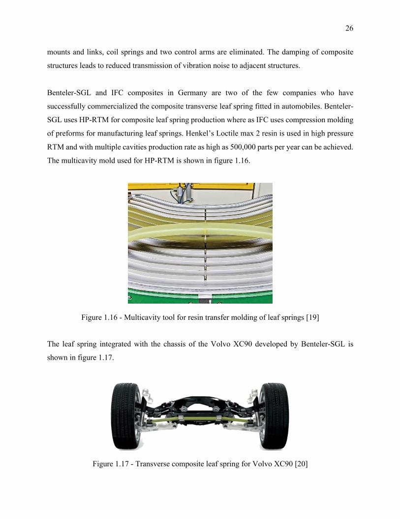
The leaf spring integrated with the chassis of the Volvo XC90 developed by Benteler-SGL is
shown in figure 1.17.
Figure 1.17 - Transverse composite leaf spring for Volvo XC90 [20]
27
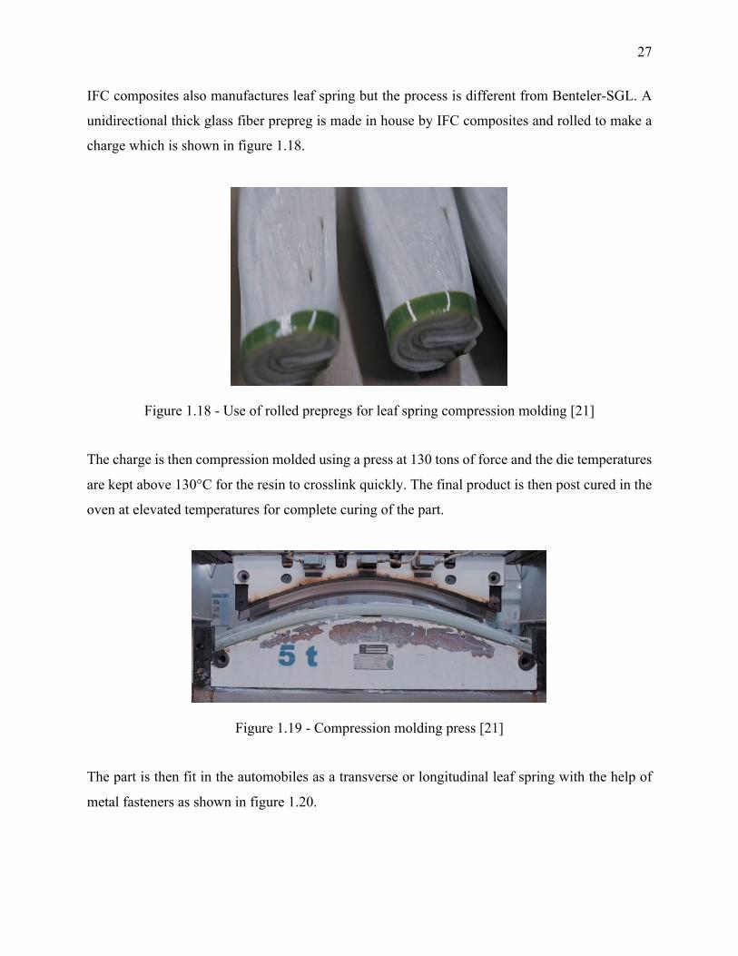
IFC composites also manufactures leaf spring but the process is different from Benteler-SGL. A
unidirectional thick glass fiber prepreg is made in house by IFC composites and rolled to make a
charge which is shown in figure 1.18.
Figure 1.18 - Use of rolled prepregs for leaf spring compression molding [21]
The charge is then compression molded using a press at 130 tons of force and the die temperatures
are kept above 130°C for the resin to crosslink quickly. The final product is then post cured in the
oven at elevated temperatures for complete curing of the part.
Figure 1.19 - Compression molding press [21]
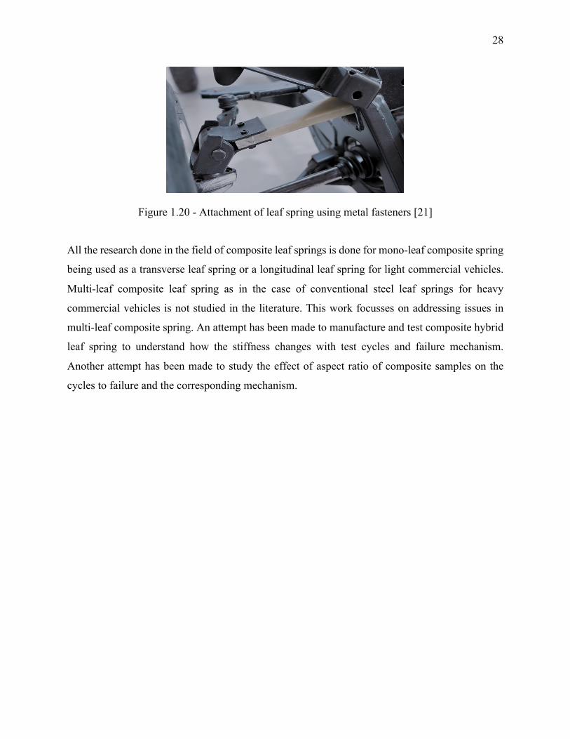
The part is then fit in the automobiles as a transverse or longitudinal leaf spring with the help of
metal fasteners as shown in figure 1.20.
28
Figure 1.20 - Attachment of leaf spring using metal fasteners [21]
All the research done in the field of composite leaf springs is done for mono-leaf composite spring
being used as a transverse leaf spring or a longitudinal leaf spring for light commercial vehicles.
Multi-leaf composite leaf spring as in the case of conventional steel leaf springs for heavy
commercial vehicles is not studied in the literature. This work focusses on addressing issues in
multi-leaf composite spring. An attempt has been made to manufacture and test composite hybrid
leaf spring to understand how the stiffness changes with test cycles and failure mechanism.
Another attempt has been made to study the effect of aspect ratio of composite samples on the
cycles to failure and the corresponding mechanism.
29
2. THEORY BEHIND LEAF SPRING DESIGN
Design elements for leaf spring
2.1.1 Spring Eyes
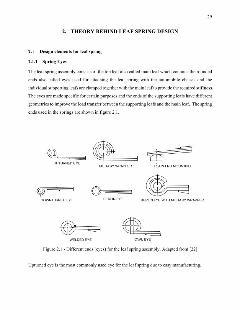
The leaf spring assembly consists of the top leaf also called main leaf which contains the rounded
ends also called eyes used for attaching the leaf spring with the automobile chassis and the
individual supporting leafs are clamped together with the main leaf to provide the required stiffness.
The eyes are made specific for certain purposes and the ends of the supporting leafs have different
geometries to improve the load transfer between the supporting leafs and the main leaf. The spring
ends used in the springs are shown in figure 2.1.
Figure 2.1 - Different ends (eyes) for the leaf spring assembly. Adapted from [22]
Upturned eye is the most commonly used eye for the leaf spring due to easy manufacturing.
+ +
++
+
UPTURNED EYEMILITARY WRAPPER PLAIN END MOUNTING
DOWNTURNED EYE BERLIN EYE BERLIN EYE WITH MILITARY WRAPPER
OVAL EYEWELDED EYE
+
30
Military wrapper design is widely used for military vehicles as the second leaf provides emergency
support in case the main leaf eye breaks. The second leaf eye may also assist the main leaf eye in
severe loads and rebounces where the two leafs come in contact and provide extra strength.
The plain end mounting type is used where the shackles cannot be fit due to space restrictions and
the curved or flat end of the leaf spring is then supported against the curved of flat rubber pads for
accommodating the change in length of the leaf spring due to deflection.
Downturned eye is used to provide a certain suspension motion to improve power steering or axle
control and is not recommended if the support from the second leaf is required.
Berlin eye is used when horizontal forces are significant and the geometry avoids the eye to unwrap
as compared to upturned eye. Berlin eye with military wrapper has the same function as military
wrapper discussed above.
The welded eye is used where the horizontal forces are too high and might lead to unwrapping of
the eye. The welding ensures that the eye is not unwrapped. The welding must be done before the
heat treatment of the spring to avoid the formation of residual stresses.
Oval eye is used to reduce the magnitude of the horizontal forces in the suspension system and
have rubber bushings with different rates in the vertical and the horizontal direction.
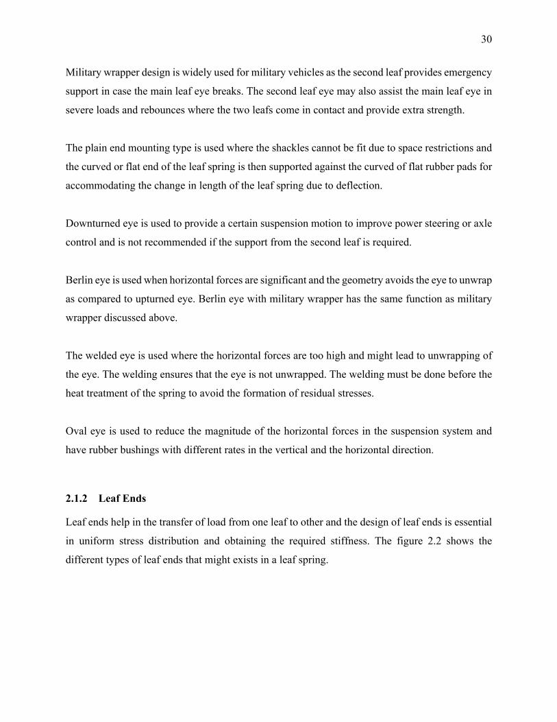
2.1.2 Leaf Ends
Leaf ends help in the transfer of load from one leaf to other and the design of leaf ends is essential
in uniform stress distribution and obtaining the required stiffness. The figure 2.2 shows the
different types of leaf ends that might exists in a leaf spring.
31
Figure 2.2 - Different types of leaf ends. Adapted from [22]
Square end – The edge of the leaf directly rubs on the leaf above thus creating stress concentrations
due to the sharp edge and leads to increase in friction. It is a poor design for uniform strength
spring and is heavier in weight than uniform stress spring.
End Tapered - The leafs are tapered using a roller and the tapering increases the contact area which
leads to better load distribution and the taper can be controlled to give very close uniform stress
distribution state for the leaf spring.
End trimmed with diamond point – The diamond point design is a better design than square end
design and is a better approximation of the uniform stress state of the spring. The load transfer is
slightly improved than the square end design for the leaf spring.
End squared and then trimmed – It is like the tapered end except to the fact that the end is later
trimmed after the tapering operation and thus giving the maximum area of contact.
2.1.3 Center Bolt
Center Bolt – The center bolt is required to hold all leafs together and the head of the bolt is used
for locating the position of installation on the axle. The head of the bolt should be below the
END SQUARE AS SHEARED END TAPERED
END TRIMMED WITH DIAMOND POINTEND SQUARE THEN TRIMMED
BURRS AWAY FROM BEARING SURFACE
32
shortest leaf for overslung spring and above the main leaf for underslung spring. The torque applied
to the bolt is high to cause deformations in the bolt so that the bolt does not loosen up due to
vibrations. The portion of the leaf where center bolt is attached is not active while the leaf spring
is in action due to fact that the area surrounding the center bolt is clamped and attached to the axle.
The inactive length of the leaf spring depends upon the installation setup and generally vary
between 8-15% of the leaf spring length. Since the region around the center bolt is clamped and
inactive the stress concentrations occurring due to the hole geometry are not substantial to consider
while designing. The diameter of the center bolt is recommended to be at least the thickness of the
heaviest leaf to enable cold punching otherwise heating the area may be required to punch the hole
of required size.
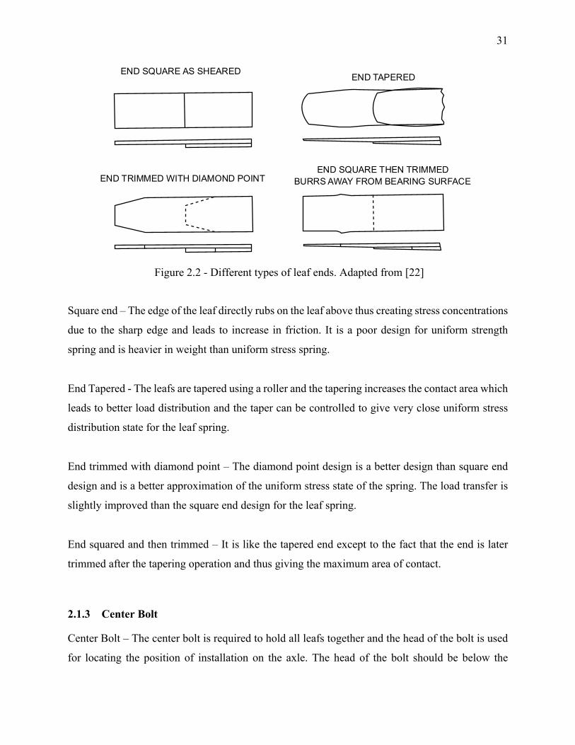
2.1.4 Center Clamp
Center Clamp – It is used to permanently tie the leaf spring with the seat surface on the axle of the
vehicle using U bolts. The benefit of center clamp is that the spring remains in position and avoids
the breaking of the center bolt due to horizontal forces. The width of the clamp reduces the active
length of the spring and the ends are well rounded to avoid any sharp contact with the leaf spring.
To effectively control the noise transmission rubber pads are used between the leaf spring and the
clamp and the amount of softness is dictated by road holding, axle control and steering control.
Figure 2.3 - U bolt assembly used for clamping leaf spring to axle
Clamping
using U bolt
33
2.1.5 Shackles
Shackle – Shackles are necessary links between the chassis and the leaf spring which allow the
motion of one end of the leaf spring relative to the other with deflection of the spring. This avoids
the problem of indeterminate system which would have been the case if both the ends of the leaf
spring were hinged with the chassis. Shackles affect the rate of the spring with its angular position
which lead to different ride characteristics from design. The figures 1.5 and 1.6 show the
attachment of leaf spring in the vehicle.
2.1.6 Variable rate leaf spring
These types of leaf spring provide variable spring rate with the increase in load after a certain load.
They are mainly used to vehicles in which the load variation is too high and ride comfort is required.
Low stiffness for initial loads ensures better ride quality and the stiffness increases with the
increase in load after a specific load limit. This ensures low stiffness at low loads and hence better
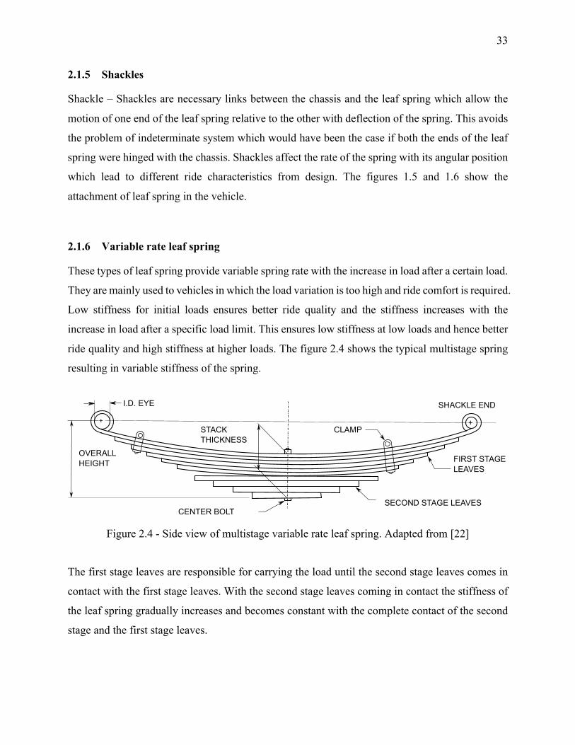
ride quality and high stiffness at higher loads. The figure 2.4 shows the typical multistage spring
resulting in variable stiffness of the spring.
Figure 2.4 - Side view of multistage variable rate leaf spring. Adapted from [22]
The first stage leaves are responsible for carrying the load until the second stage leaves comes in
contact with the first stage leaves. With the second stage leaves coming in contact the stiffness of
the leaf spring gradually increases and becomes constant with the complete contact of the second
stage and the first stage leaves.
SECOND STAGE LEAVESCENTER BOLT
STACK THICKNESS
FIRST STAGELEAVES
CLAMP
OVERALLHEIGHT
+ +
I.D. EYE SHACKLE END
34
Design considerations and calculations for leaf spring
Beams in bending have a uniform cross section throughout the length and the variation in bending
moment leads to non-uniform stress distribution across the length of the leaf spring. This leads to
wastage of material as all section of material are not completely loaded to the max stress. The
stress formula in a beam is given by equation 2.1.
𝜎 = #$% (2.1)
where M is the applied moment, y is the distance from the neutral axis and I is the moment of
inertia. With the change in M, if the moment of inertia is also changed so that the stress remains
at peak with a factor of safety then the resulting beam is called a beam with uniform strength. This
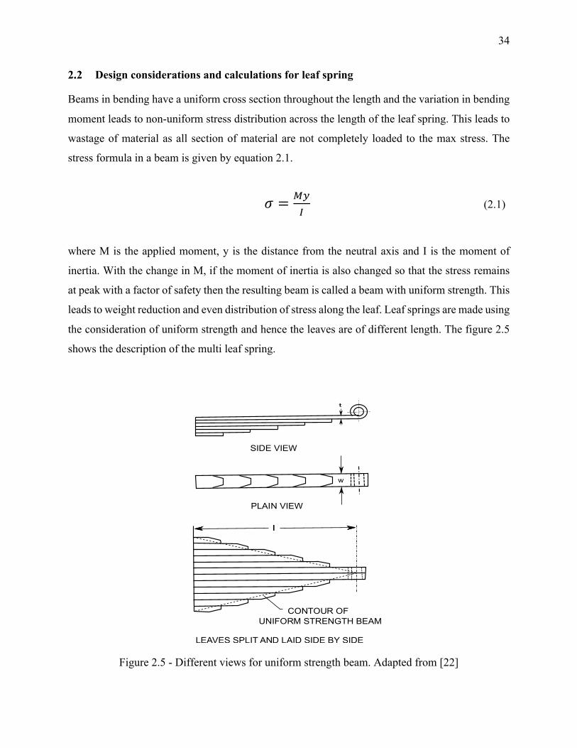
leads to weight reduction and even distribution of stress along the leaf. Leaf springs are made using
the consideration of uniform strength and hence the leaves are of different length. The figure 2.5
shows the description of the multi leaf spring.
Figure 2.5 - Different views for uniform strength beam. Adapted from [22]
w
t
SIDE VIEW
PLAIN VIEW
CONTOUR OFUNIFORM STRENGTH BEAM
LEAVES SPLIT AND LAID SIDE BY SIDE
35
Uniform section spring with the same load, length, thickness and stress produces two-third of the
deflection and weighs twice as much as the uniform strength spring. Hence, the uniform strength
spring is thrice as efficient as uniform section spring. By applying the Euler Bernoulli beam
formulas, the stress and deflection can be found out using the load and the geometry of the beam.
The stress can be calculated from load as well as deflection and both formulas give an insight to
the design of leaf spring. The stress from load formula is stated in the equation 2.2.
𝜎 = #$%= '()*
+*,= '()
+*- (2.2)
Where h is the leaf thickness, L the length of cantilever beam, b the width of the beam and P the applied load. From formula 2.2 the stress is directly proportional to the length of the beam and inversely
proportional to the square of the thickness of the beam. The stress from deflection formula states
that the stress is directly proportional to the thickness of the beam and inversely proportional to
the length square of the beam. The two formula seem paradoxical but in the stress from load
formula the deflection is not considered and the stress from deflection formula can be obtained by
substituting the load with stiffness times the deflection.
𝜎 = #$%= '()
+*-= './)
+*- (2.3)
For a cantilever beam with load applied at one tip the deflection and load are related and given in
equation 2.4.
𝛿 = (),
12%,𝐾 = (
/= 12%
), (2.4)
Substituting the value of k from equation 2.4 in equation 2.3 we get
𝜎 = 6 ∗ 12%),∗ /)+*-
= 17∗ 2*/
)- (2.5)
36
The equation 2.5 directly relates the stress and displacement and states the stress is directly
proportional to the leaf thickness and inversely proportional to the length square. The formula
signifies that for given stress and deflection the thickness of the leaf is directly proportional to the
square of the length. Since thin leafs cannot provide enough strength to the spring eyes the length
of the spring should be increased to account for the increased thickness. Also, the windup stiffness
varies as square of the length and hence it is desirable to have large length but the length is also
constrained to the available space and the mounting points on the chassis.
Stiffening factor – The approximation of uniform strength for a leaf spring is not completely valid
and the stresses need to be adjusted using a stiffening factor. The factors described below
determine how closely the leaf spring matches the approximation for the uniform strength spring.
1. Length of the leaves is not consistent with the uniform strength formula and this is
specifically done for reduce the stress in the eye region. The length of the second leaf is
sometimes made equal to the length of the main leaf to reduce the stress in the eye region.
2. Leaf ends of different geometries provide an approximation of uniform strength since they
exceed the outline of the triangular beam.
3. Centre clamp reduces the active length of the spring and the procedure states testing of the
leaf spring without the center clamp as the formulae are derived for the unclamped
condition. The length in the formulae can be replaced by active length by subtracting the
clamped length from the total length of the spring. The active length in the spring depends
upon the clamping parts and the rubber pads used for support in the clamping of the leaf
spring. In case of semi-elliptic cantilever beams the active length extends into the seat area
and hence the active length is larger than the distance between the outside edge of the clamp
and the point of application of load. In case of springs without liner material the active
length is the distance from the load point to the inside edge of the clamp bolt.
The effect of the above-mentioned factors needs to be accounted for in the formulae with a
stiffening factor which is denoted by SF. SF has an exact value of 1 when the leaves follow the
length and thickness according to the ones derived from uniform strength formula. The farther the
spring deviates from the uniform strength parameters the higher would be the stiffening factor.
The value of SF ranges from 1 to 1.50 and the value 1 corresponds to uniform strength design
37
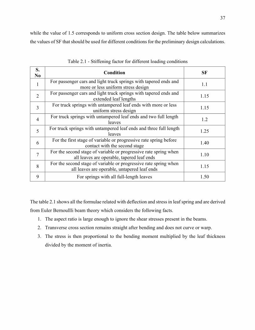
while the value of 1.5 corresponds to uniform cross section design. The table below summarizes
the values of SF that should be used for different conditions for the preliminary design calculations.
Table 2.1 - Stiffening factor for different loading conditions
S. No Condition SF
1 For passenger cars and light truck springs with tapered ends and more or less uniform stress design 1.1
2 For passenger cars and light truck springs with tapered ends and extended leaf lengths 1.15
3 For truck springs with untampered leaf ends with more or less uniform stress design 1.15
4 For truck springs with untampered leaf ends and two full length leaves 1.2
5 For truck springs with untampered leaf ends and three full length leaves 1.25
6 For the first stage of variable or progressive rate spring before contact with the second stage 1.40
7 For the second stage of variable or progressive rate spring when all leaves are operable, tapered leaf ends 1.10
8 For the second stage of variable or progressive rate spring when all leaves are operable, untapered leaf ends 1.15
9 For springs with all full-length leaves 1.50
The table 2.1 shows all the formulae related with deflection and stress in leaf spring and are derived
from Euler Bernoullli beam theory which considers the following facts.
1. The aspect ratio is large enough to ignore the shear stresses present in the beams.
2. Transverse cross section remains straight after bending and does not curve or warp.
3. The stress is then proportional to the bending moment multiplied by the leaf thickness
divided by the moment of inertia.
38
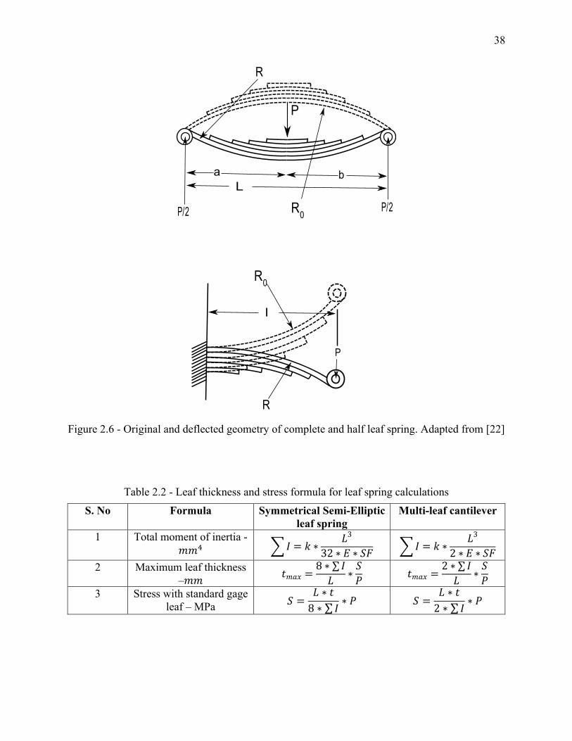
Figure 2.6 - Original and deflected geometry of complete and half leaf spring. Adapted from [22]
Table 2.2 - Leaf thickness and stress formula for leaf spring calculations
S. No Formula Symmetrical Semi-Elliptic leaf spring
Multi-leaf cantilever
1 Total moment of inertia - 𝑚𝑚9 :𝐼 = 𝑘 ∗
𝐿3
32 ∗ 𝐸 ∗ 𝑆𝐹 :𝐼 = 𝑘 ∗𝐿3
2 ∗ 𝐸 ∗ 𝑆𝐹
2 Maximum leaf thickness –𝑚𝑚 𝑡𝑚𝑎𝑥 =
8 ∗ ∑ 𝐼𝐿 ∗
𝑆𝑃 𝑡𝑚𝑎𝑥 =
2 ∗ ∑ 𝐼𝐿 ∗
𝑆𝑃
3 Stress with standard gage leaf – MPa 𝑆 =
𝐿 ∗ 𝑡8 ∗ ∑ 𝐼 ∗ 𝑃 𝑆 =
𝐿 ∗ 𝑡2 ∗ ∑ 𝐼 ∗ 𝑃
La b
P
R
P/2 P/2
P
l
R0
R0
R
39
The formulas in table 2.2 are valid for semi-elliptical leaf spring where the span of the spring on
either side of the center bolt is equal. If the span is unequal and the span ratio is greater than a
certain number then the formulas in table 2.2 cannot be used and different set of formulas should
be used.
L- length of the semi-elliptic spring
l- length of cantilever spring
a – front length of the semi elliptic spring
b – rear length of the semi elliptic spring
P – load on spring
f – deflection on spring
k – load rate
∑I – total moment of inertia
tmax – maximum leaf thickness
S – stress with selected gauge
SF – stiffening factor
The formulas discussed in table 2.2 are required for preliminary design calculations for spring.
The first formula establishes the moment of inertia for the required rate and length. The 2nd formula
tell the permissible leaf thickness at a corresponding load for a given max stress and the 3rd formula
is used to calculate the maximum stress in the spring. For unsymmetrical springs with the length
ratio of less than 1.3 the formulae corresponding to the symmetrical beams can be used but the
results will not be completely accurate and within 3% of those obtained from complicated
unsymmetrical beam formulae.
Leaf thickness obtained from the formulae signify the maximum leaf thickness that can be used
but all leafs are not made with the same maximum gauge thickness. The main leaf is generally one
gauge thicker than the shorter leafs and this is done to provide more strength to the eyes of the
spring and more tolerance on quench radius on the shorter leaves. One other big reason for
choosing leaves with different thicknesses is that the required moment of inertia is achieved more
closely than using leaves with same gauge thickness. This helps in obtaining the load rate close to
what is required in practice.
40
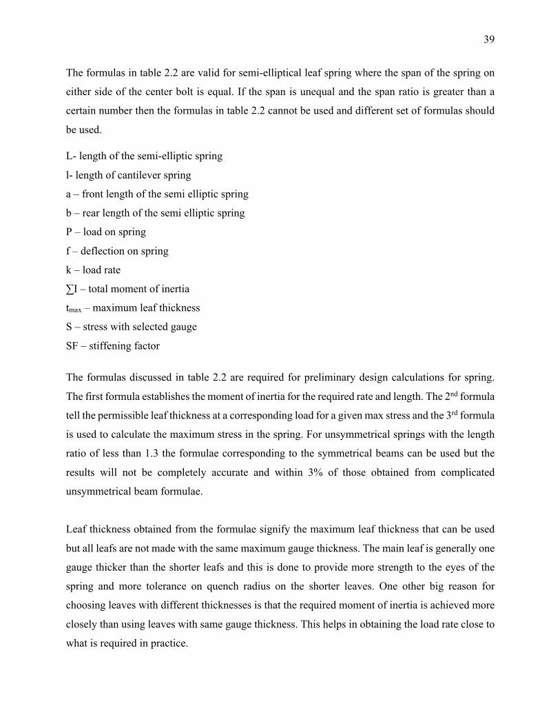
Stepping – The length of different leaves in the spring determine the stress distribution along the
length of the leaf. The shape and rate of the spring under load is determined by leaves length,
thickness and leaf radii. The center of pressure is the point on the leaf where it contacts the upper
leaf and the load transfer takes place and is different from the end of the leaf. In case of blunt ends
the it may be 10 mm inside of the leaf end or in case of tapered leaf the distance may be as large
as 50 mm inside the leaf. The distance between a point of contact and the adjacent point of contact
is called the overhang. To determine the overhang of the shortest leaf the geometry of the clamp
should be considered. All the overhangs summed together determine the active length of the spring.
In case of beams shown in figure 2.7 where all the leaves are made of same thickness and radii,
equal overhang or step would be given to resemble uniform strength spring as close as possible.
Figure 2.7 - Uniform overhang and thickness spring. Adapted from [22]
If the spring has different gauge thickness, then the step should be given proportional to t3. This
would make the stresses uniform along the length of the leaf, but different leaves may be stresses
differently which may not be beneficial for fatigue life endurance. Sometimes the second leaf is as
the same length of the main leaf and this is done to reduce the stresses near the eye area and results
in increase in stiffness of the spring. However, the stress at the edge of the clamps remain the same
and if the load is increased then the stress would increase too no matter the length of other leaves.
If springs with different curvatures are assembled together then assembly stresses are set up which
are desirable for various other reasons. With the introduction of assembly stresses, it is impossible
to have a uniform stress distribution across the length of the leaf for all loads. With suitable
assembly stresses and leaf stepping the stresses can be made uniform along the length for a load.
The spring when assembly with assembly stresses or assembled dead (same curvature for all leaf)
have the same stiffness value for the same leaf radii, thickness and length.
w
t
SIDE VIEW
PLAIN VIEW
CONTOUR OFUNIFORM STRENGTH BEAM
LEAVES SPLIT AND LAID SIDE BY SIDE
41
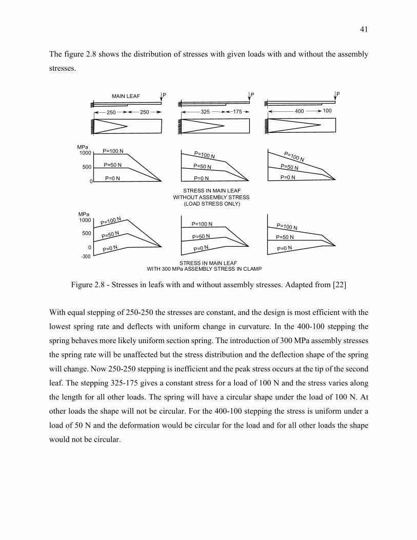
The figure 2.8 shows the distribution of stresses with given loads with and without the assembly
stresses.
Figure 2.8 - Stresses in leafs with and without assembly stresses. Adapted from [22]
With equal stepping of 250-250 the stresses are constant, and the design is most efficient with the
lowest spring rate and deflects with uniform change in curvature. In the 400-100 stepping the
spring behaves more likely uniform section spring. The introduction of 300 MPa assembly stresses
the spring rate will be unaffected but the stress distribution and the deflection shape of the spring
will change. Now 250-250 stepping is inefficient and the peak stress occurs at the tip of the second
leaf. The stepping 325-175 gives a constant stress for a load of 100 N and the stress varies along
the length for all other loads. The spring will have a circular shape under the load of 100 N. At
other loads the shape will not be circular. For the 400-100 stepping the stress is uniform under a
load of 50 N and the deformation would be circular for the load and for all other loads the shape
would not be circular.
STRESS IN MAIN LEAFWITH 300 MPa ASSEMBLY STRESS IN CLAMP
STRESS IN MAIN LEAFWITHOUT ASSEMBLY STRESS
(LOAD STRESS ONLY)
P=100 N
P=100 N
P=100 N
P=50 N
P=0 N
P=50 N
P=0 N
P=100 N
P=50 N
P=0 N
P=50 N
P=0 N
P=100 N
P=0 N
P=50 N
P=0 N
P=50 N
P=100 N
MPa
MPa
1000
1000
500
0
500
0-300
MAIN LEAF P P P
250 250 325 175 400 100
42
Figure 2.9 - Effect of assembly stresses on short and long leaves. Adapted from [22]
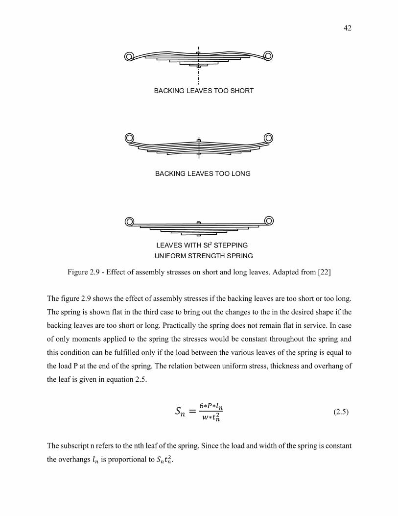
The figure 2.9 shows the effect of assembly stresses if the backing leaves are too short or too long.
The spring is shown flat in the third case to bring out the changes to the in the desired shape if the
backing leaves are too short or long. Practically the spring does not remain flat in service. In case
of only moments applied to the spring the stresses would be constant throughout the spring and
this condition can be fulfilled only if the load between the various leaves of the spring is equal to
the load P at the end of the spring. The relation between uniform stress, thickness and overhang of
the leaf is given in equation 2.5.
𝑆I ='∗(∗JKL∗MK-
(2.5)
The subscript n refers to the nth leaf of the spring. Since the load and width of the spring is constant
the overhangs 𝑙I is proportional to 𝑆I𝑡I7.
BACKING LEAVES TOO SHORT
BACKING LEAVES TOO LONG
LEAVES WITH St2 STEPPINGUNIFORM STRENGTH SPRING
43
𝑙I ∝ 𝑆I𝑡I7 (2.6)
Since the introduction to assembly stresses lead to uniform stress distribution only for a load it is
important to decide what load should be selected for uniform stress distribution. For over the road
vehicles experience has shown that if the stresses under the normal load are made uniform then
best service is obtained.
The load transfer can take place between the leaves at a point or along the complete curvature.
These two assumptions are called “point pressure” and “common curvature”. For the point
pressure method the leaves touch only at the ends and at the clamp center. This can be observed
by the location of wear and tear after the spring has been in service. After calculating the tip load
each individual spring can be considered as an individual beam for calculation. Generally, spacers
are provided between the leaf at the center clamp to enable point contact and nylon pads are
provided at the ends of the leafs to avoid metal to metal contact for friction and heat purposes.
Common curvatures mean that all the length of the spring is in contact with the other leaf and the
load transfer happens through the common curvature. This assumption leads to simpler
calculations. In some cases the assumption of point pressure and common curvature leads to same
results.
The analysis and design of a leaf spring can thus be considered as a combination of 4 stages:
1. Preliminary calculations for no of leaves, leaf thickness and stress.
2. Finding leaf length and radii of individual leaf and stress distribution at one load.
3. Finding stress at various points in the spring by common curvature or point pressure
method.
4. Find the accuracy of the assumptions using a FEM model or strain gauges.
Strength of spring eyes – The eye of the spring will tend to open with the application of longitudinal
forces due to braking or other shock forces. The formula for calculating the stress due to the
horizontal forces is given in equation 2.7.
𝑆 = 1P(RSM)M-L
(2.7)
44
The stress formula given in the equation applies to upturned, downturned and berlin eyes except
in the case of berlin eyes that the stress is zero in case of compressive longitudinal forces which
gives an added benefit to berlin eyes over the other two. In Hotchkiss drive suspension system a
high factor of safety should be considered due to the presence of large horizontal braking and
driving longitudinal forces. Hence, the maximum stress should not be allowed to increase than 350
MPa to ensure high safety factor.
Stresses due to press fitting of bushing in the eye can also be calculated from the formula 2.8.
𝑆 = 9U∗ ∆2M(RSM)-
(2.8)
The stress due to press fit and longitudinal forces are additive in nature. Also, the axial force and
torque obtained without slipping between the eye and the bushing will depend upon the finish,
hardness and degree of lubrication of the engaging surfaces.
∆ −Difference between OD of bushing and ID of eye
𝑆 −Stress
𝐷 − ID of the spring eye
𝑡 −Thickness of leaf at eye
𝑤 − Width of the leaf at eye
𝐸 − Modulus of elasticity (200 GPa)
𝐹 − Longitudinal forces
Installation effects – For the measurement of the spring stiffness the spring is deflected with load
applied on the clamping area and rollers on the support for the spring to roll due to change in length
of the spring. However, the spring stiffness varies when it is installed in the vehicles due to the
installation of center clamps and shackles. By understanding the underlying mechanics of shackles
and center clamp extensive installation testing can be avoided and the knowledge will be useful in
obtaining the desired static or variable rates as required with the use of shackles.
45
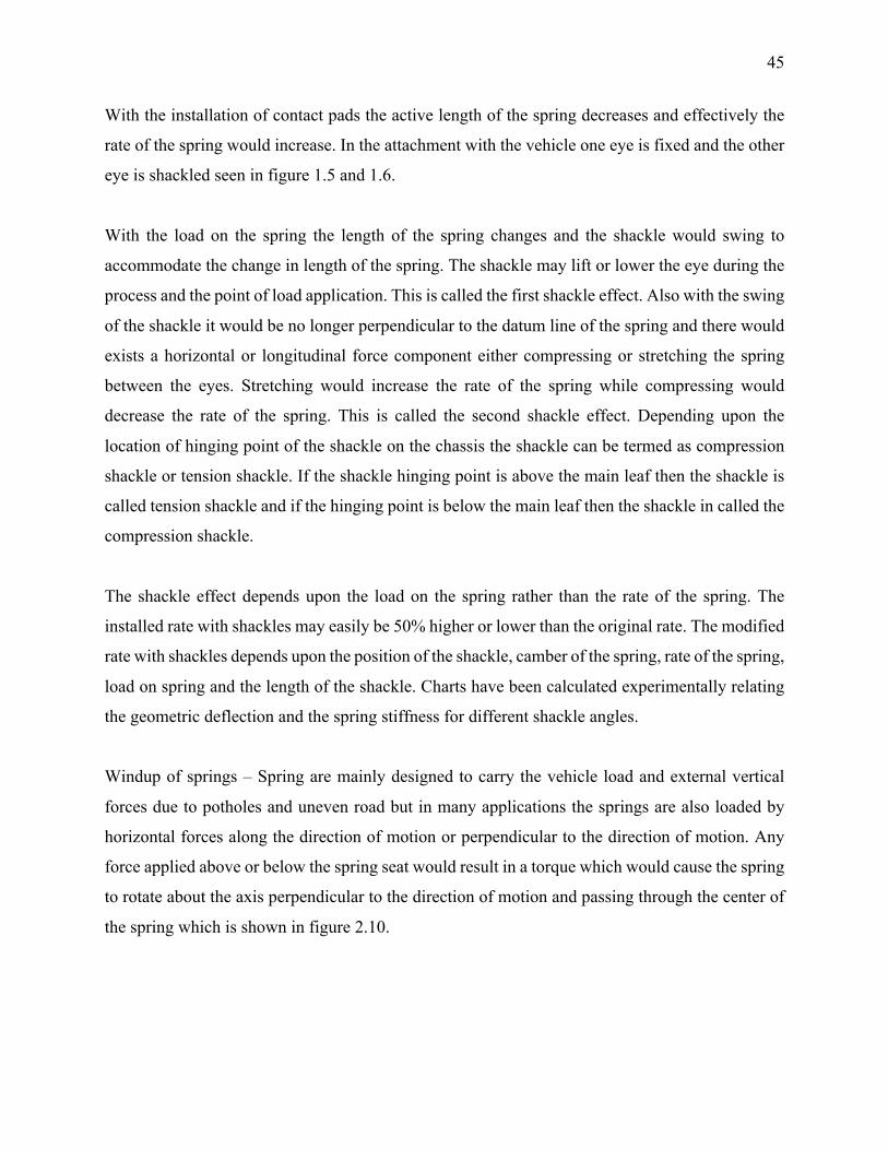
With the installation of contact pads the active length of the spring decreases and effectively the
rate of the spring would increase. In the attachment with the vehicle one eye is fixed and the other
eye is shackled seen in figure 1.5 and 1.6.
With the load on the spring the length of the spring changes and the shackle would swing to
accommodate the change in length of the spring. The shackle may lift or lower the eye during the
process and the point of load application. This is called the first shackle effect. Also with the swing
of the shackle it would be no longer perpendicular to the datum line of the spring and there would
exists a horizontal or longitudinal force component either compressing or stretching the spring
between the eyes. Stretching would increase the rate of the spring while compressing would
decrease the rate of the spring. This is called the second shackle effect. Depending upon the
location of hinging point of the shackle on the chassis the shackle can be termed as compression
shackle or tension shackle. If the shackle hinging point is above the main leaf then the shackle is
called tension shackle and if the hinging point is below the main leaf then the shackle in called the
compression shackle.
The shackle effect depends upon the load on the spring rather than the rate of the spring. The
installed rate with shackles may easily be 50% higher or lower than the original rate. The modified
rate with shackles depends upon the position of the shackle, camber of the spring, rate of the spring,
load on spring and the length of the shackle. Charts have been calculated experimentally relating
the geometric deflection and the spring stiffness for different shackle angles.
Windup of springs – Spring are mainly designed to carry the vehicle load and external vertical
forces due to potholes and uneven road but in many applications the springs are also loaded by
horizontal forces along the direction of motion or perpendicular to the direction of motion. Any
force applied above or below the spring seat would result in a torque which would cause the spring
to rotate about the axis perpendicular to the direction of motion and passing through the center of
the spring which is shown in figure 2.10.
46
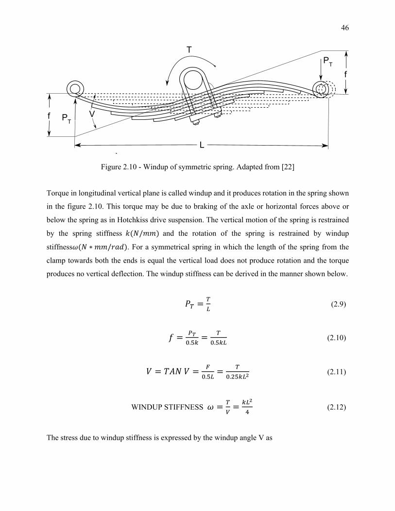
Figure 2.10 - Windup of symmetric spring. Adapted from [22]
Torque in longitudinal vertical plane is called windup and it produces rotation in the spring shown
in the figure 2.10. This torque may be due to braking of the axle or horizontal forces above or
below the spring as in Hotchkiss drive suspension. The vertical motion of the spring is restrained
by the spring stiffness 𝑘(𝑁/𝑚𝑚) and the rotation of the spring is restrained by windup
stiffness𝜔(𝑁 ∗ 𝑚𝑚/𝑟𝑎𝑑). For a symmetrical spring in which the length of the spring from the
clamp towards both the ends is equal the vertical load does not produce rotation and the torque
produces no vertical deflection. The windup stiffness can be derived in the manner shown below.
𝑃_ =_)
(2.9)
𝑓 = (ab.de
= _b.de)
(2.10)
𝑉 = 𝑇𝐴𝑁𝑉 = Pb.d)
= _b.7de)-
(2.11)
WINDUP STIFFNESS 𝜔 = _i= e)-
9 (2.12)
The stress due to windup stiffness is expressed by the windup angle V as
L
f
f
PT
`
PT
T
V
47
𝑆j =72M)∗ 𝑉 ∗ 𝑆𝐹 (2.13)
The equation 2.13 can also be expressed by torque T as
𝑆j =k2Me),
∗ 𝑇 ∗ 𝑆𝐹 = 7_e)∗ lm
(2.14)
where S is the stress caused by the deflection f, SF is the stiffening factor and V is the windup
angle.
The formula 2.14 indicate the importance of length in distribution of stresses due to rotation which
is inversely proportional to L and the effect of length on windup stiffness which is inversely
proportional to L2 which can be seen in formula 2.12. Hence large leaf length increases the windup
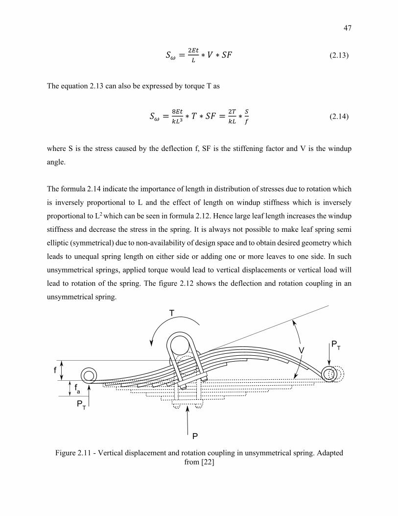
stiffness and decrease the stress in the spring. It is always not possible to make leaf spring semi
elliptic (symmetrical) due to non-availability of design space and to obtain desired geometry which
leads to unequal spring length on either side or adding one or more leaves to one side. In such
unsymmetrical springs, applied torque would lead to vertical displacements or vertical load will
lead to rotation of the spring. The figure 2.12 shows the deflection and rotation coupling in an
unsymmetrical spring.
Figure 2.11 - Vertical displacement and rotation coupling in unsymmetrical spring. Adapted from [22]
f
fa
P
PT
PTV
T
48
Twist of springs – Other factor to consider while designing is the twist of the spring which may
occur due to pothole or/and obstacle under one wheel of an axle. Twisting of leaf spring by 𝛼
degrees in length l will produce a shear stress of
𝑆 = o9bbMpJ
𝑀𝑃𝑎(𝐴𝑝𝑟𝑟𝑜𝑥. ) (2.15)
And torque:
𝑇 = 97bLM,pJ
𝑁 ∗ 𝑚𝑚(𝐴𝑝𝑝𝑟𝑜𝑥. ) (2.16)
To keep the length of twist as long as possible the clips used to hold leafs together for alignment
should not stop the main leaf from twisting. With the shackles and brackets being flexible the
stresses developed due to twisting of the spring would reduce.
49
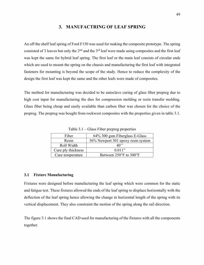
3. MANUFACTRING OF LEAF SPRING
An off the shelf leaf spring of Ford F150 was used for making the composite prototype. The spring
consisted of 3 leaves but only the 2nd and the 3rd leaf were made using composites and the first leaf
was kept the same for hybrid leaf spring. The first leaf or the main leaf consists of circular ends
which are used to mount the spring on the chassis and manufacturing the first leaf with integrated
fasteners for mounting is beyond the scope of the study. Hence to reduce the complexity of the
design the first leaf was kept the same and the other leafs were made of composites.
The method for manufacturing was decided to be autoclave curing of glass fiber prepreg due to
high cost input for manufacturing the dies for compression molding or resin transfer molding.
Glass fiber being cheap and easily available than carbon fiber was chosen for the choice of the
prepreg. The prepreg was bought from rockwest composites with the properties given in table 3.1.
Table 3.1 – Glass Fiber prepreg properties
Fiber 64% 300 gsm Fiberglass E-Glass Resin 36% Newport 301 epoxy resin system
Roll Width 40’’ Cure ply thickness 0.011” Cure temperature Between 250°F to 300°F
Fixture Manufacturing
Fixtures were designed before manufacturing the leaf spring which were common for the static
and fatigue test. These fixtures allowed the ends of the leaf spring to displace horizontally with the
deflection of the leaf spring hence allowing the change in horizontal length of the spring with its
vertical displacement. They also constraint the motion of the spring along the rail direction.
The figure 3.1 shows the final CAD used for manufacturing of the fixtures with all the components
together.
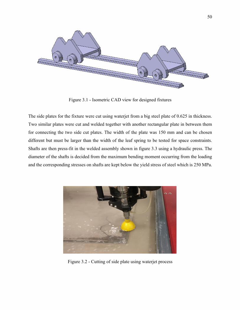
50
Figure 3.1 - Isometric CAD view for designed fixtures
The side plates for the fixture were cut using waterjet from a big steel plate of 0.625 in thickness.
Two similar plates were cut and welded together with another rectangular plate in between them
for connecting the two side cut plates. The width of the plate was 150 mm and can be chosen
different but must be larger than the width of the leaf spring to be tested for space constraints.
Shafts are then press-fit in the welded assembly shown in figure 3.3 using a hydraulic press. The
diameter of the shafts is decided from the maximum bending moment occurring from the loading
and the corresponding stresses on shafts are kept below the yield stress of steel which is 250 MPa.
Figure 3.2 - Cutting of side plate using waterjet process
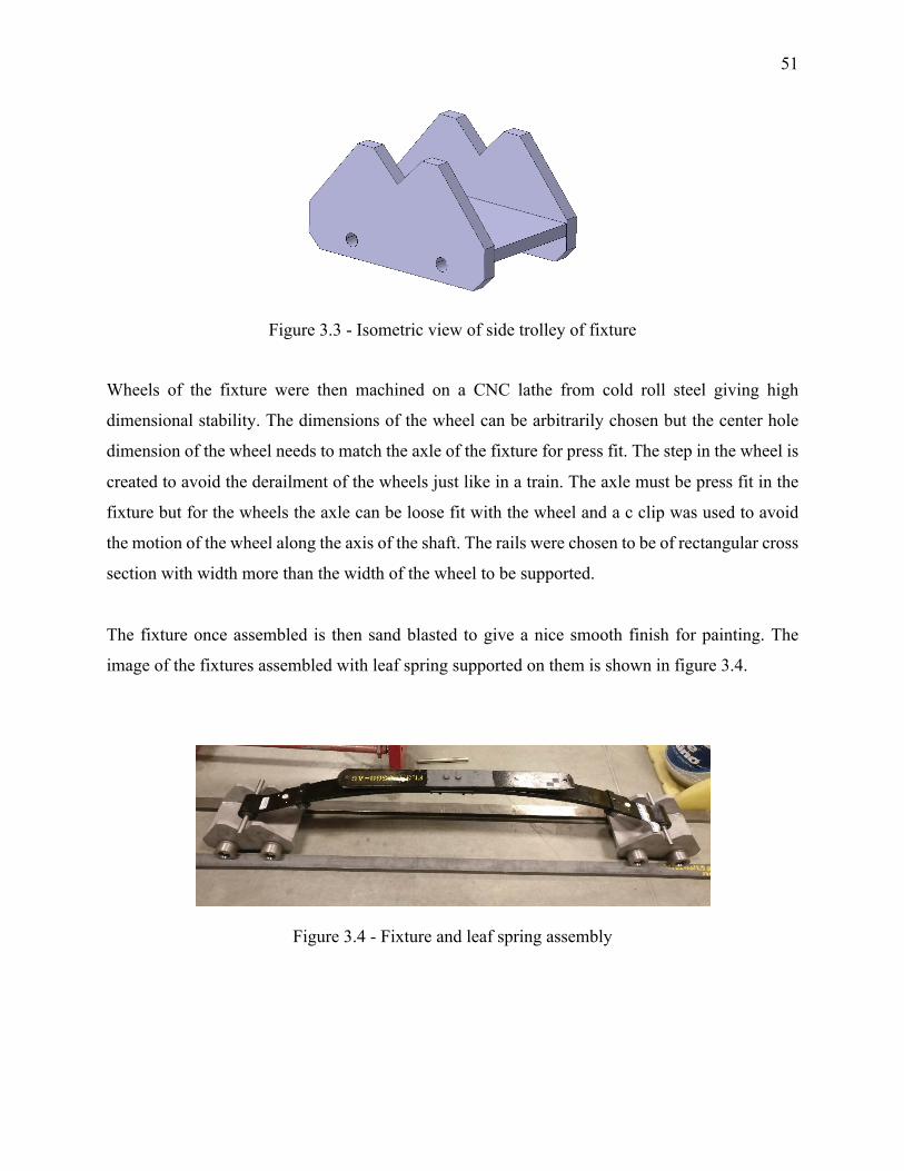
51
Figure 3.3 - Isometric view of side trolley of fixture
Wheels of the fixture were then machined on a CNC lathe from cold roll steel giving high
dimensional stability. The dimensions of the wheel can be arbitrarily chosen but the center hole
dimension of the wheel needs to match the axle of the fixture for press fit. The step in the wheel is
created to avoid the derailment of the wheels just like in a train. The axle must be press fit in the
fixture but for the wheels the axle can be loose fit with the wheel and a c clip was used to avoid
the motion of the wheel along the axis of the shaft. The rails were chosen to be of rectangular cross
section with width more than the width of the wheel to be supported.
The fixture once assembled is then sand blasted to give a nice smooth finish for painting. The
image of the fixtures assembled with leaf spring supported on them is shown in figure 3.4.
Figure 3.4 - Fixture and leaf spring assembly
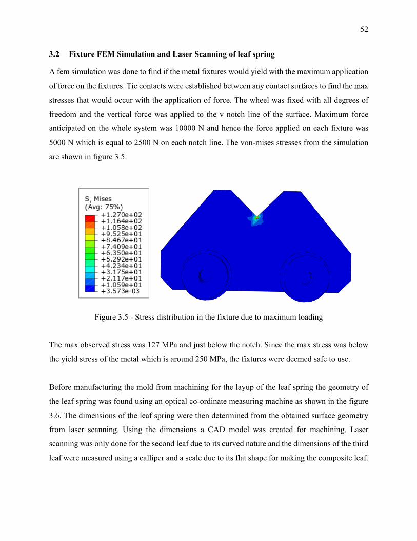
52
Fixture FEM Simulation and Laser Scanning of leaf spring
A fem simulation was done to find if the metal fixtures would yield with the maximum application
of force on the fixtures. Tie contacts were established between any contact surfaces to find the max
stresses that would occur with the application of force. The wheel was fixed with all degrees of
freedom and the vertical force was applied to the v notch line of the surface. Maximum force
anticipated on the whole system was 10000 N and hence the force applied on each fixture was
5000 N which is equal to 2500 N on each notch line. The von-mises stresses from the simulation
are shown in figure 3.5.
Figure 3.5 - Stress distribution in the fixture due to maximum loading
The max observed stress was 127 MPa and just below the notch. Since the max stress was below
the yield stress of the metal which is around 250 MPa, the fixtures were deemed safe to use.
Before manufacturing the mold from machining for the layup of the leaf spring the geometry of
the leaf spring was found using an optical co-ordinate measuring machine as shown in the figure
3.6. The dimensions of the leaf spring were then determined from the obtained surface geometry
from laser scanning. Using the dimensions a CAD model was created for machining. Laser
scanning was only done for the second leaf due to its curved nature and the dimensions of the third
leaf were measured using a calliper and a scale due to its flat shape for making the composite leaf.
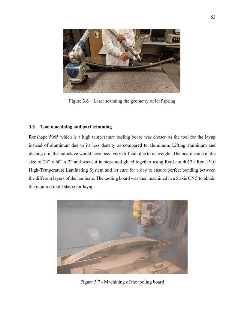
53
Figure 3.6 – Laser scanning the geometry of leaf spring
Tool machining and part trimming
Renshape 5065 which is a high temperature tooling board was chosen as the tool for the layup
instead of aluminum due to its less density as compared to aluminum. Lifting aluminum and
placing it in the autoclave would have been very difficult due to its weight. The board came in the
size of 24” x 60” x 2” and was cut in steps and glued together using RenLam 4017 / Ren 1510
High-Temperature Laminating System and let cure for a day to ensure perfect bonding between
the different layers of the laminate. The tooling board was then machined in a 5 axis CNC to obtain
the required mold shape for layup.
Figure 3.7 - Machining of the tooling board
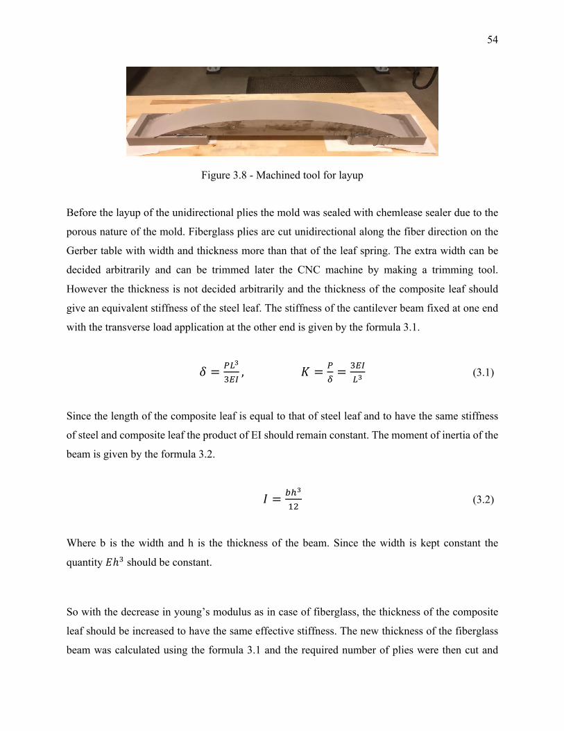
54
Figure 3.8 - Machined tool for layup
Before the layup of the unidirectional plies the mold was sealed with chemlease sealer due to the
porous nature of the mold. Fiberglass plies are cut unidirectional along the fiber direction on the
Gerber table with width and thickness more than that of the leaf spring. The extra width can be
decided arbitrarily and can be trimmed later the CNC machine by making a trimming tool.
However the thickness is not decided arbitrarily and the thickness of the composite leaf should
give an equivalent stiffness of the steel leaf. The stiffness of the cantilever beam fixed at one end
with the transverse load application at the other end is given by the formula 3.1.
𝛿 = (),
12%,𝐾 = (
/= 12%
), (3.1)
Since the length of the composite leaf is equal to that of steel leaf and to have the same stiffness
of steel and composite leaf the product of EI should remain constant. The moment of inertia of the
beam is given by the formula 3.2.
𝐼 = +*,
o7 (3.2)
Where b is the width and h is the thickness of the beam. Since the width is kept constant the
quantity 𝐸ℎ1 should be constant.
So with the decrease in young’s modulus as in case of fiberglass, the thickness of the composite
leaf should be increased to have the same effective stiffness. The new thickness of the fiberglass
beam was calculated using the formula 3.1 and the required number of plies were then cut and
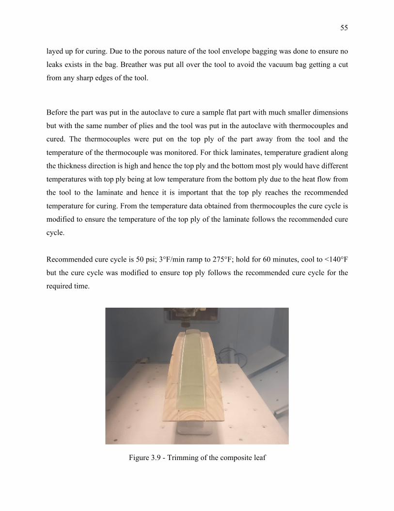
55
layed up for curing. Due to the porous nature of the tool envelope bagging was done to ensure no
leaks exists in the bag. Breather was put all over the tool to avoid the vacuum bag getting a cut
from any sharp edges of the tool.
Before the part was put in the autoclave to cure a sample flat part with much smaller dimensions
but with the same number of plies and the tool was put in the autoclave with thermocouples and
cured. The thermocouples were put on the top ply of the part away from the tool and the
temperature of the thermocouple was monitored. For thick laminates, temperature gradient along
the thickness direction is high and hence the top ply and the bottom most ply would have different
temperatures with top ply being at low temperature from the bottom ply due to the heat flow from
the tool to the laminate and hence it is important that the top ply reaches the recommended
temperature for curing. From the temperature data obtained from thermocouples the cure cycle is
modified to ensure the temperature of the top ply of the laminate follows the recommended cure
cycle.
Recommended cure cycle is 50 psi; 3°F/min ramp to 275°F; hold for 60 minutes, cool to <140°F
but the cure cycle was modified to ensure top ply follows the recommended cure cycle for the
required time.
Figure 3.9 - Trimming of the composite leaf
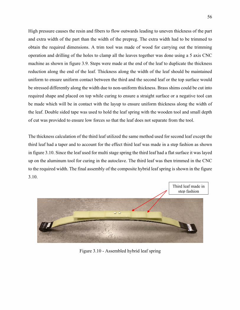
56
High pressure causes the resin and fibers to flow outwards leading to uneven thickness of the part
and extra width of the part than the width of the prepreg. The extra width had to be trimmed to
obtain the required dimensions. A trim tool was made of wood for carrying out the trimming
operation and drilling of the holes to clamp all the leaves together was done using a 5 axis CNC
machine as shown in figure 3.9. Steps were made at the end of the leaf to duplicate the thickness
reduction along the end of the leaf. Thickness along the width of the leaf should be maintained
uniform to ensure uniform contact between the third and the second leaf or the top surface would
be stressed differently along the width due to non-uniform thickness. Brass shims could be cut into
required shape and placed on top while curing to ensure a straight surface or a negative tool can
be made which will be in contact with the layup to ensure uniform thickness along the width of
the leaf. Double sided tape was used to hold the leaf spring with the wooden tool and small depth
of cut was provided to ensure low forces so that the leaf does not separate from the tool.
The thickness calculation of the third leaf utilized the same method used for second leaf except the
third leaf had a taper and to account for the effect third leaf was made in a step fashion as shown
in figure 3.10. Since the leaf used for multi stage spring the third leaf had a flat surface it was layed
up on the aluminum tool for curing in the autoclave. The third leaf was then trimmed in the CNC
to the required width. The final assembly of the composite hybrid leaf spring is shown in the figure
3.10.
Figure 3.10 - Assembled hybrid leaf spring
Third leaf made in step fashion
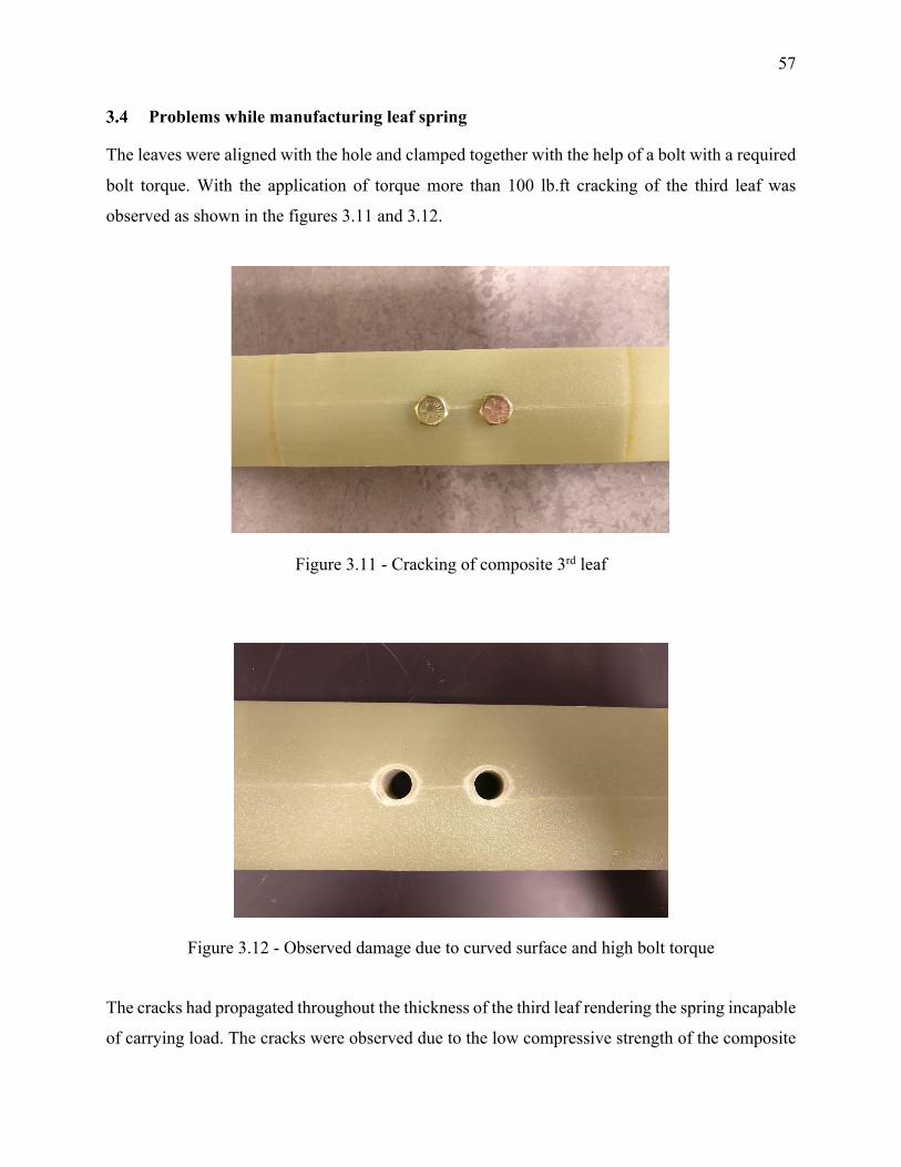
57
Problems while manufacturing leaf spring
The leaves were aligned with the hole and clamped together with the help of a bolt with a required
bolt torque. With the application of torque more than 100 lb.ft cracking of the third leaf was
observed as shown in the figures 3.11 and 3.12.
Figure 3.11 - Cracking of composite 3rd leaf
Figure 3.12 - Observed damage due to curved surface and high bolt torque
The cracks had propagated throughout the thickness of the third leaf rendering the spring incapable
of carrying load. The cracks were observed due to the low compressive strength of the composite
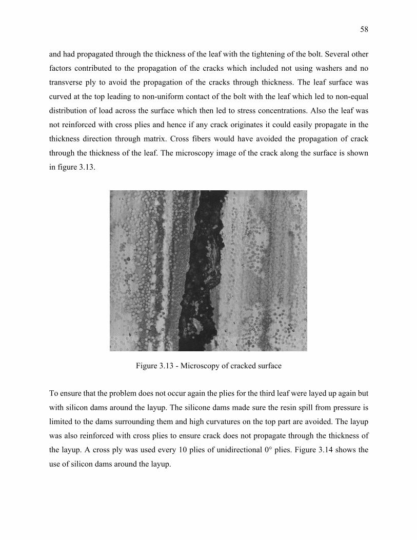
58
and had propagated through the thickness of the leaf with the tightening of the bolt. Several other
factors contributed to the propagation of the cracks which included not using washers and no
transverse ply to avoid the propagation of the cracks through thickness. The leaf surface was
curved at the top leading to non-uniform contact of the bolt with the leaf which led to non-equal
distribution of load across the surface which then led to stress concentrations. Also the leaf was
not reinforced with cross plies and hence if any crack originates it could easily propagate in the
thickness direction through matrix. Cross fibers would have avoided the propagation of crack
through the thickness of the leaf. The microscopy image of the crack along the surface is shown
in figure 3.13.
Figure 3.13 - Microscopy of cracked surface
To ensure that the problem does not occur again the plies for the third leaf were layed up again but
with silicon dams around the layup. The silicone dams made sure the resin spill from pressure is
limited to the dams surrounding them and high curvatures on the top part are avoided. The layup
was also reinforced with cross plies to ensure crack does not propagate through the thickness of
the layup. A cross ply was used every 10 plies of unidirectional 0° plies. Figure 3.14 shows the
use of silicon dams around the layup.
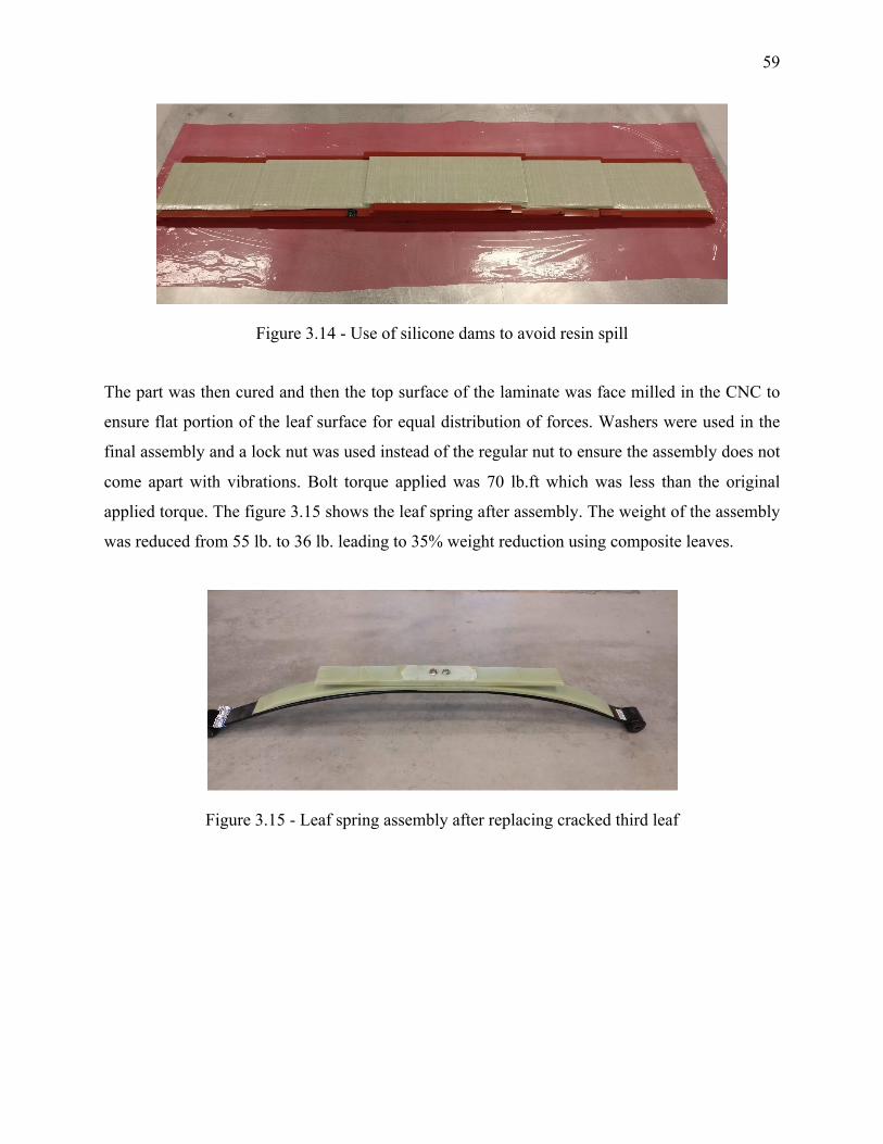
59
Figure 3.14 - Use of silicone dams to avoid resin spill
The part was then cured and then the top surface of the laminate was face milled in the CNC to
ensure flat portion of the leaf surface for equal distribution of forces. Washers were used in the
final assembly and a lock nut was used instead of the regular nut to ensure the assembly does not
come apart with vibrations. Bolt torque applied was 70 lb.ft which was less than the original
applied torque. The figure 3.15 shows the leaf spring after assembly. The weight of the assembly
was reduced from 55 lb. to 36 lb. leading to 35% weight reduction using composite leaves.
Figure 3.15 - Leaf spring assembly after replacing cracked third leaf
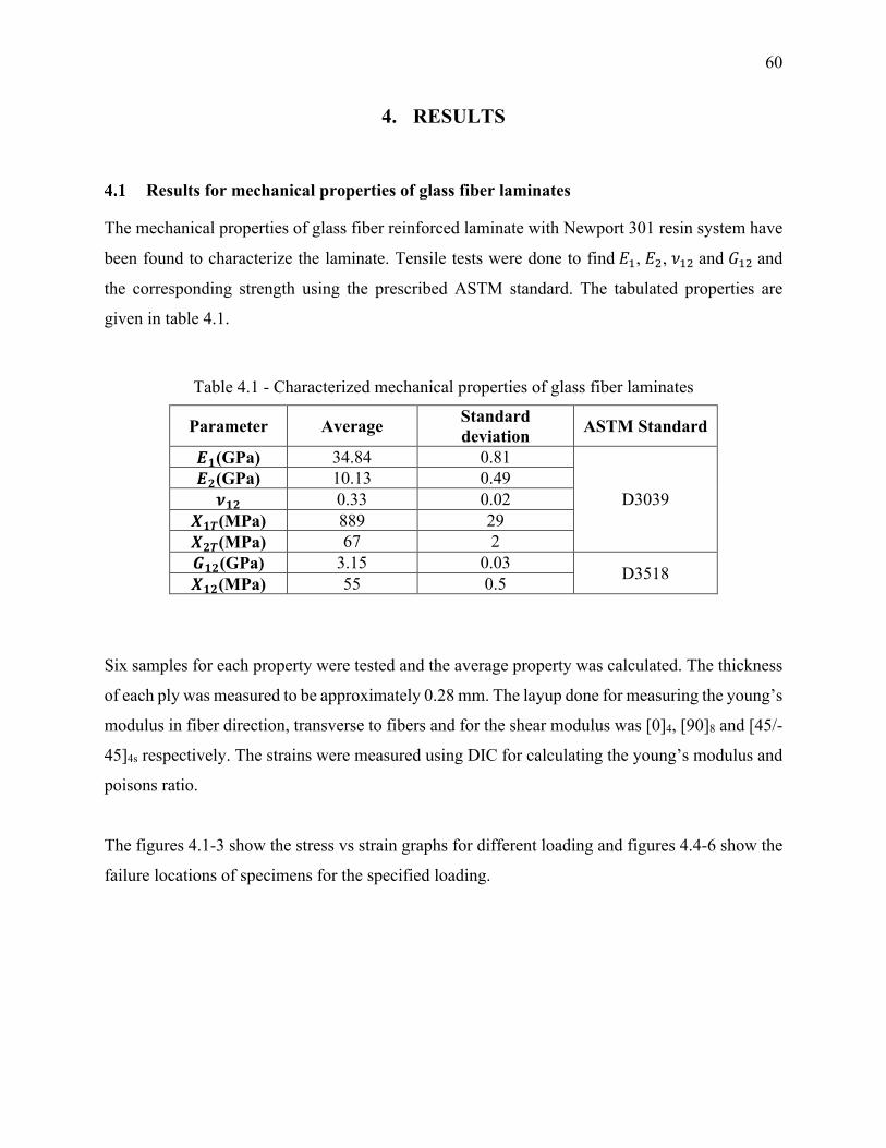
60
4. RESULTS
Results for mechanical properties of glass fiber laminates
The mechanical properties of glass fiber reinforced laminate with Newport 301 resin system have
been found to characterize the laminate. Tensile tests were done to find𝐸o, 𝐸7, 𝜈o7 and 𝐺o7 and
the corresponding strength using the prescribed ASTM standard. The tabulated properties are
given in table 4.1.
Table 4.1 - Characterized mechanical properties of glass fiber laminates
Parameter Average Standard deviation ASTM Standard
𝑬𝟏(GPa) 34.84 0.81
D3039 𝑬𝟐(GPa) 10.13 0.49 𝝂𝟏𝟐 0.33 0.02
𝑿𝟏𝑻(MPa) 889 29 𝑿𝟐𝑻(MPa) 67 2 𝑮𝟏𝟐(GPa) 3.15 0.03 D3518 𝑿𝟏𝟐(MPa) 55 0.5
Six samples for each property were tested and the average property was calculated. The thickness
of each ply was measured to be approximately 0.28 mm. The layup done for measuring the young’s
modulus in fiber direction, transverse to fibers and for the shear modulus was [0]4, [90]8 and [45/-
45]4s respectively. The strains were measured using DIC for calculating the young’s modulus and
poisons ratio.
The figures 4.1-3 show the stress vs strain graphs for different loading and figures 4.4-6 show the
failure locations of specimens for the specified loading.
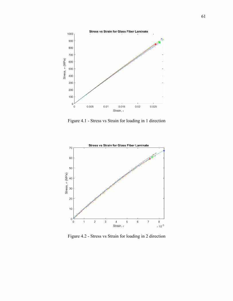
61
Figure 4.1 - Stress vs Strain for loading in 1 direction
Figure 4.2 - Stress vs Strain for loading in 2 direction
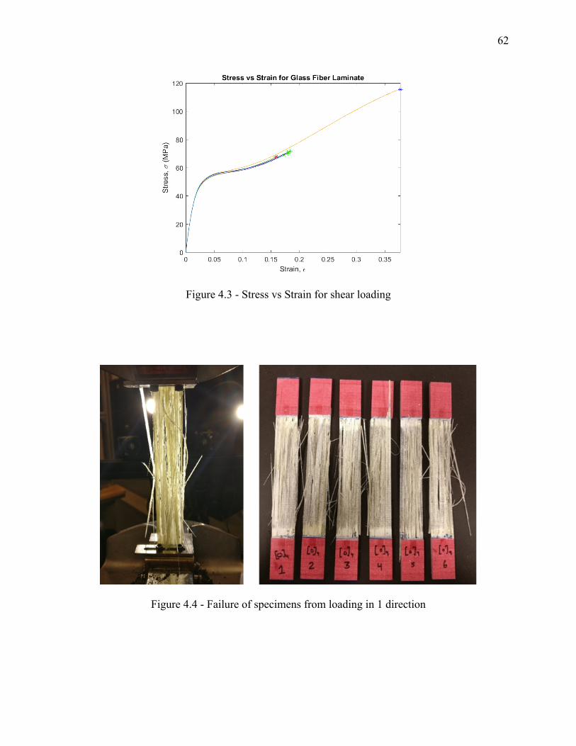
62
Figure 4.3 - Stress vs Strain for shear loading
Figure 4.4 - Failure of specimens from loading in 1 direction
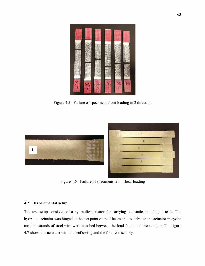
63
Figure 4.5 - Failure of specimens from loading in 2 direction
- Figure 4.6 - Failure of specimens from shear loading
Experimental setup
The test setup consisted of a hydraulic actuator for carrying out static and fatigue tests. The
hydraulic actuator was hinged at the top point of the I beam and to stabilize the actuator in cyclic
motions strands of steel wire were attached between the load frame and the actuator. The figure
4.7 shows the actuator with the leaf spring and the fixture assembly.
1
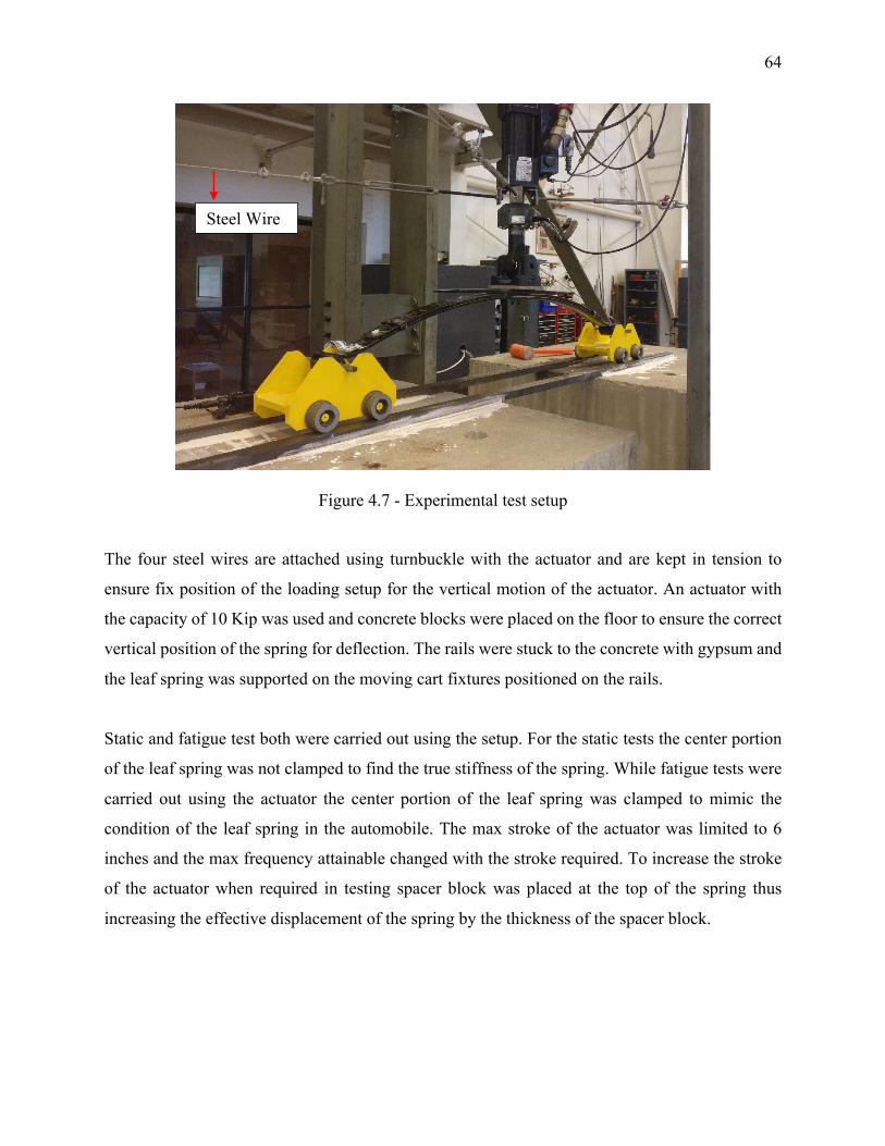
64
Figure 4.7 - Experimental test setup
The four steel wires are attached using turnbuckle with the actuator and are kept in tension to
ensure fix position of the loading setup for the vertical motion of the actuator. An actuator with
the capacity of 10 Kip was used and concrete blocks were placed on the floor to ensure the correct
vertical position of the spring for deflection. The rails were stuck to the concrete with gypsum and
the leaf spring was supported on the moving cart fixtures positioned on the rails.
Static and fatigue test both were carried out using the setup. For the static tests the center portion
of the leaf spring was not clamped to find the true stiffness of the spring. While fatigue tests were
carried out using the actuator the center portion of the leaf spring was clamped to mimic the
condition of the leaf spring in the automobile. The max stroke of the actuator was limited to 6
inches and the max frequency attainable changed with the stroke required. To increase the stroke
of the actuator when required in testing spacer block was placed at the top of the spring thus
increasing the effective displacement of the spring by the thickness of the spacer block.
Steel Wire
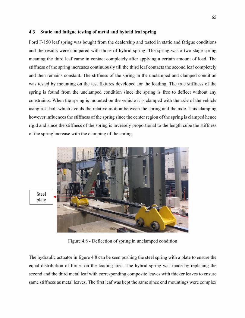
65
Static and fatigue testing of metal and hybrid leaf spring
Ford F-150 leaf spring was bought from the dealership and tested in static and fatigue conditions
and the results were compared with those of hybrid spring. The spring was a two-stage spring
meaning the third leaf came in contact completely after applying a certain amount of load. The
stiffness of the spring increases continuously till the third leaf contacts the second leaf completely
and then remains constant. The stiffness of the spring in the unclamped and clamped condition
was tested by mounting on the test fixtures developed for the loading. The true stiffness of the
spring is found from the unclamped condition since the spring is free to deflect without any
constraints. When the spring is mounted on the vehicle it is clamped with the axle of the vehicle
using a U bolt which avoids the relative motion between the spring and the axle. This clamping
however influences the stiffness of the spring since the center region of the spring is clamped hence
rigid and since the stiffness of the spring is inversely proportional to the length cube the stiffness
of the spring increase with the clamping of the spring.
Figure 4.8 - Deflection of spring in unclamped condition
The hydraulic actuator in figure 4.8 can be seen pushing the steel spring with a plate to ensure the
equal distribution of forces on the loading area. The hybrid spring was made by replacing the
second and the third metal leaf with corresponding composite leaves with thicker leaves to ensure
same stiffness as metal leaves. The first leaf was kept the same since end mountings were complex
Steel plate
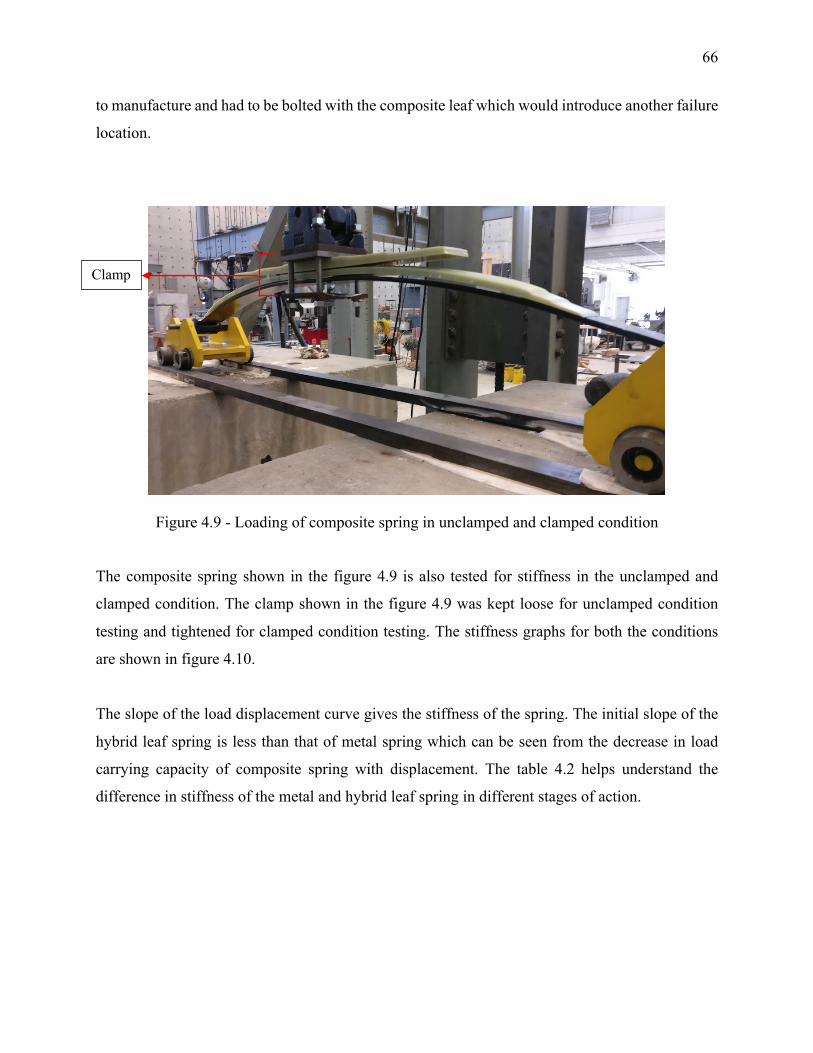
66
to manufacture and had to be bolted with the composite leaf which would introduce another failure
location.
Figure 4.9 - Loading of composite spring in unclamped and clamped condition
The composite spring shown in the figure 4.9 is also tested for stiffness in the unclamped and
clamped condition. The clamp shown in the figure 4.9 was kept loose for unclamped condition
testing and tightened for clamped condition testing. The stiffness graphs for both the conditions
are shown in figure 4.10.
The slope of the load displacement curve gives the stiffness of the spring. The initial slope of the
hybrid leaf spring is less than that of metal spring which can be seen from the decrease in load
carrying capacity of composite spring with displacement. The table 4.2 helps understand the
difference in stiffness of the metal and hybrid leaf spring in different stages of action.
Clamp
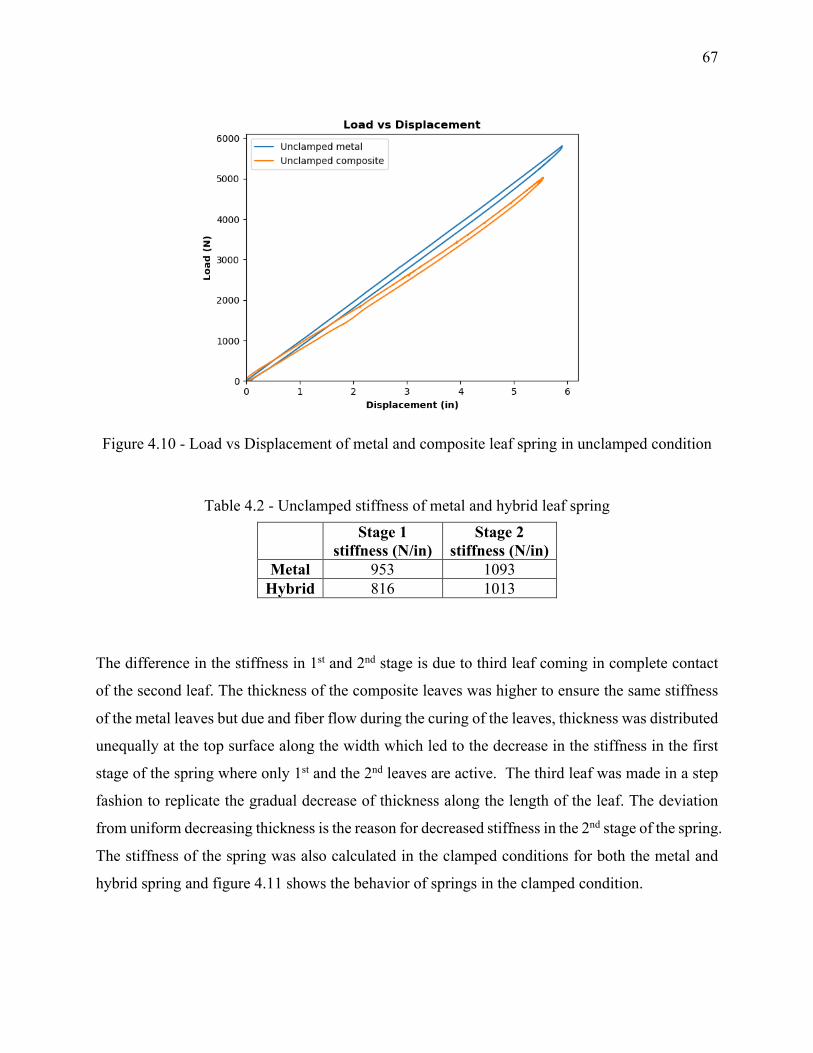
67
Figure 4.10 - Load vs Displacement of metal and composite leaf spring in unclamped condition
Table 4.2 - Unclamped stiffness of metal and hybrid leaf spring
Stage 1 stiffness (N/in)
Stage 2 stiffness (N/in)
Metal 953 1093 Hybrid 816 1013
The difference in the stiffness in 1st and 2nd stage is due to third leaf coming in complete contact
of the second leaf. The thickness of the composite leaves was higher to ensure the same stiffness
of the metal leaves but due and fiber flow during the curing of the leaves, thickness was distributed
unequally at the top surface along the width which led to the decrease in the stiffness in the first
stage of the spring where only 1st and the 2nd leaves are active. The third leaf was made in a step
fashion to replicate the gradual decrease of thickness along the length of the leaf. The deviation
from uniform decreasing thickness is the reason for decreased stiffness in the 2nd stage of the spring.
The stiffness of the spring was also calculated in the clamped conditions for both the metal and
hybrid spring and figure 4.11 shows the behavior of springs in the clamped condition.
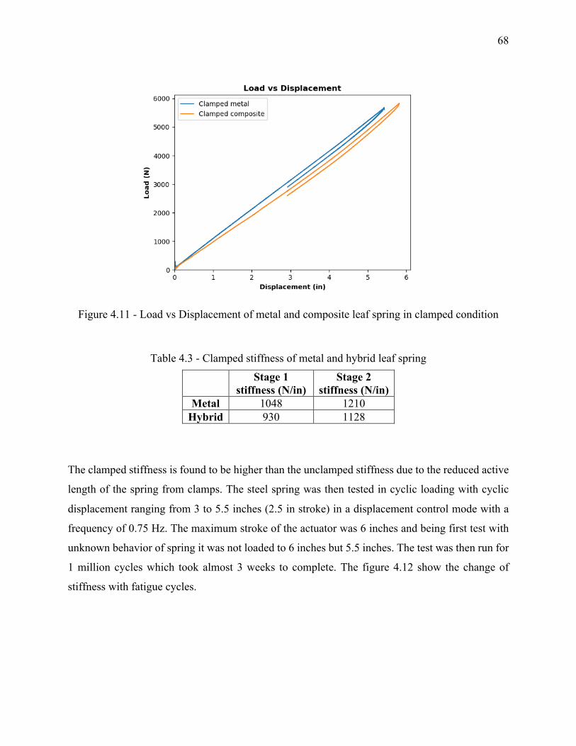
68
Figure 4.11 - Load vs Displacement of metal and composite leaf spring in clamped condition
Table 4.3 - Clamped stiffness of metal and hybrid leaf spring
Stage 1 stiffness (N/in)
Stage 2 stiffness (N/in)
Metal 1048 1210 Hybrid 930 1128
The clamped stiffness is found to be higher than the unclamped stiffness due to the reduced active
length of the spring from clamps. The steel spring was then tested in cyclic loading with cyclic
displacement ranging from 3 to 5.5 inches (2.5 in stroke) in a displacement control mode with a
frequency of 0.75 Hz. The maximum stroke of the actuator was 6 inches and being first test with
unknown behavior of spring it was not loaded to 6 inches but 5.5 inches. The test was then run for
1 million cycles which took almost 3 weeks to complete. The figure 4.12 show the change of
stiffness with fatigue cycles.
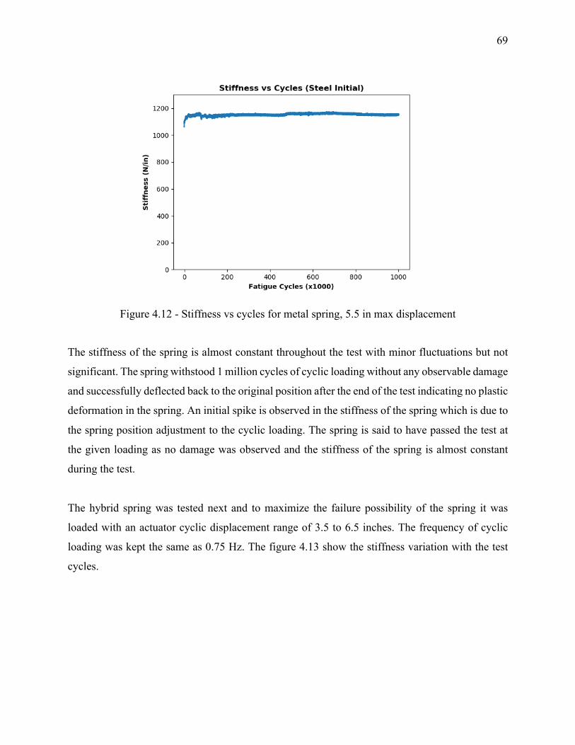
69
Figure 4.12 - Stiffness vs cycles for metal spring, 5.5 in max displacement
The stiffness of the spring is almost constant throughout the test with minor fluctuations but not
significant. The spring withstood 1 million cycles of cyclic loading without any observable damage
and successfully deflected back to the original position after the end of the test indicating no plastic
deformation in the spring. An initial spike is observed in the stiffness of the spring which is due to
the spring position adjustment to the cyclic loading. The spring is said to have passed the test at
the given loading as no damage was observed and the stiffness of the spring is almost constant
during the test.
The hybrid spring was tested next and to maximize the failure possibility of the spring it was
loaded with an actuator cyclic displacement range of 3.5 to 6.5 inches. The frequency of cyclic
loading was kept the same as 0.75 Hz. The figure 4.13 show the stiffness variation with the test
cycles.
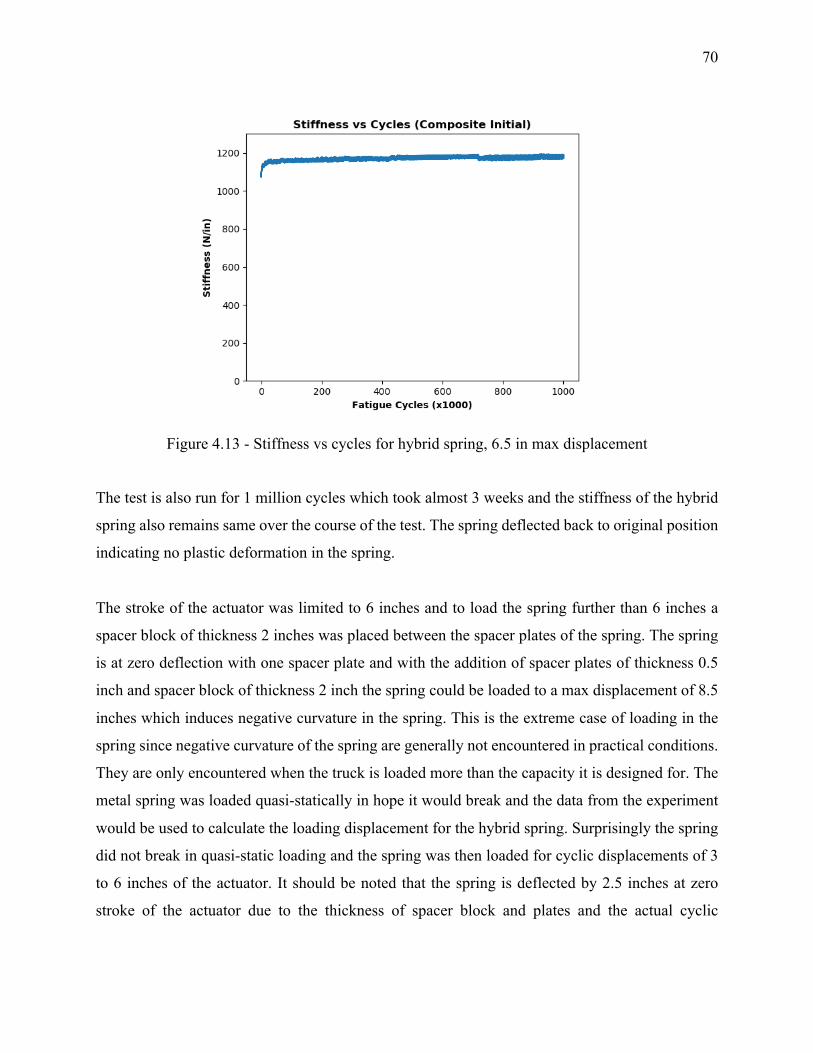
70
Figure 4.13 - Stiffness vs cycles for hybrid spring, 6.5 in max displacement
The test is also run for 1 million cycles which took almost 3 weeks and the stiffness of the hybrid
spring also remains same over the course of the test. The spring deflected back to original position
indicating no plastic deformation in the spring.
The stroke of the actuator was limited to 6 inches and to load the spring further than 6 inches a
spacer block of thickness 2 inches was placed between the spacer plates of the spring. The spring
is at zero deflection with one spacer plate and with the addition of spacer plates of thickness 0.5
inch and spacer block of thickness 2 inch the spring could be loaded to a max displacement of 8.5
inches which induces negative curvature in the spring. This is the extreme case of loading in the
spring since negative curvature of the spring are generally not encountered in practical conditions.
They are only encountered when the truck is loaded more than the capacity it is designed for. The
metal spring was loaded quasi-statically in hope it would break and the data from the experiment
would be used to calculate the loading displacement for the hybrid spring. Surprisingly the spring
did not break in quasi-static loading and the spring was then loaded for cyclic displacements of 3
to 6 inches of the actuator. It should be noted that the spring is deflected by 2.5 inches at zero
stroke of the actuator due to the thickness of spacer block and plates and the actual cyclic
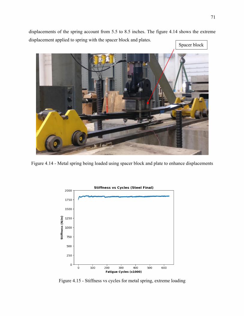
71
displacements of the spring account from 5.5 to 8.5 inches. The figure 4.14 shows the extreme
displacement applied to spring with the spacer block and plates.
Figure 4.14 - Metal spring being loaded using spacer block and plate to enhance displacements
Figure 4.15 - Stiffness vs cycles for metal spring, extreme loading
Spacer block
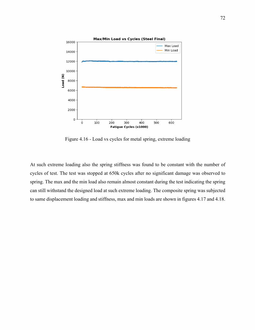
72
Figure 4.16 - Load vs cycles for metal spring, extreme loading
At such extreme loading also the spring stiffness was found to be constant with the number of
cycles of test. The test was stopped at 650k cycles after no significant damage was observed to
spring. The max and the min load also remain almost constant during the test indicating the spring
can still withstand the designed load at such extreme loading. The composite spring was subjected
to same displacement loading and stiffness, max and min loads are shown in figures 4.17 and 4.18.
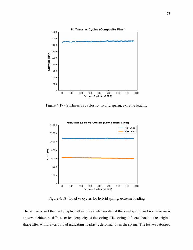
73
Figure 4.17 - Stiffness vs cycles for hybrid spring, extreme loading
Figure 4.18 - Load vs cycles for hybrid spring, extreme loading
The stiffness and the load graphs follow the similar results of the steel spring and no decrease is
observed either in stiffness or load capacity of the spring. The spring deflected back to the original
shape after withdrawal of load indicating no plastic deformation in the spring. The test was stopped
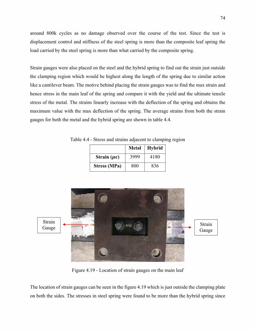
74
around 800k cycles as no damage observed over the course of the test. Since the test is
displacement control and stiffness of the steel spring is more than the composite leaf spring the
load carried by the steel spring is more than what carried by the composite spring.
Strain gauges were also placed on the steel and the hybrid spring to find out the strain just outside
the clamping region which would be highest along the length of the spring due to similar action
like a cantilever beam. The motive behind placing the strain gauges was to find the max strain and
hence stress in the main leaf of the spring and compare it with the yield and the ultimate tensile
stress of the metal. The strains linearly increase with the deflection of the spring and obtains the
maximum value with the max deflection of the spring. The average strains from both the strain
gauges for both the metal and the hybrid spring are shown in table 4.4.
Table 4.4 - Stress and strains adjacent to clamping region
Metal Hybrid
Strain (𝝁𝝐) 3999 4180
Stress (MPa) 800 836
Figure 4.19 - Location of strain gauges on the main leaf
The location of strain gauges can be seen in the figure 4.19 which is just outside the clamping plate
on both the sides. The stresses in steel spring were found to be more than the hybrid spring since
Strain Gauge
Strain Gauge
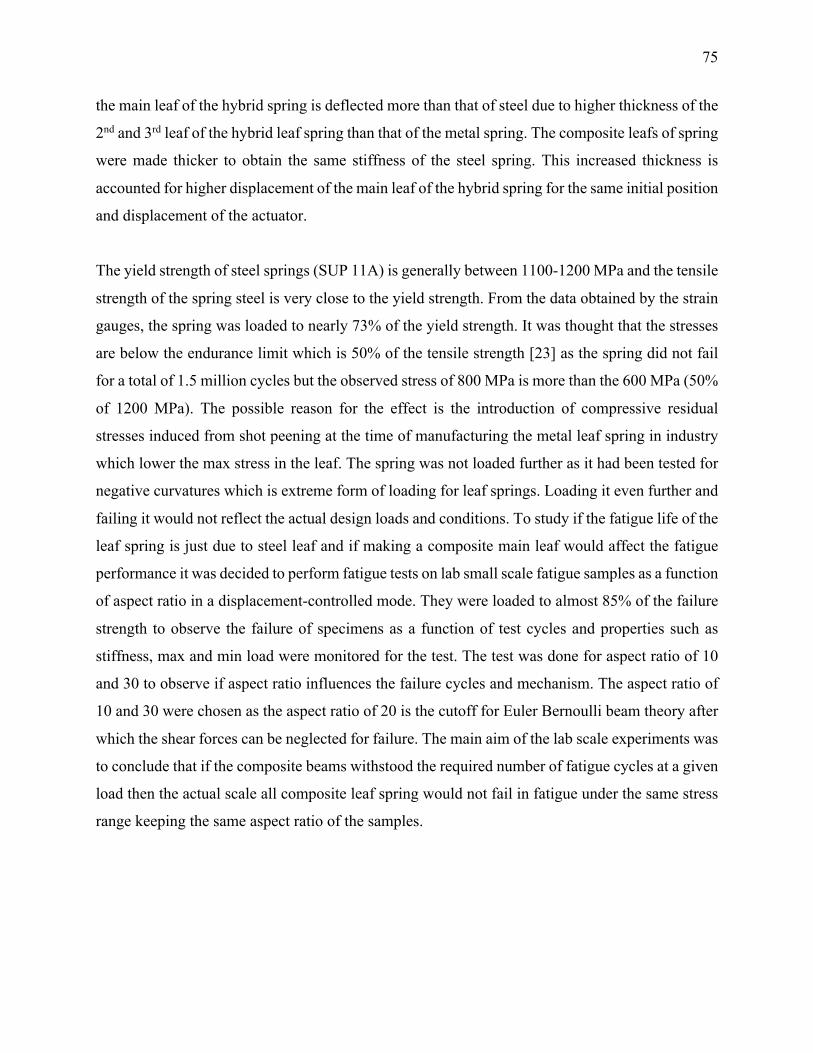
75
the main leaf of the hybrid spring is deflected more than that of steel due to higher thickness of the
2nd and 3rd leaf of the hybrid leaf spring than that of the metal spring. The composite leafs of spring
were made thicker to obtain the same stiffness of the steel spring. This increased thickness is
accounted for higher displacement of the main leaf of the hybrid spring for the same initial position
and displacement of the actuator.
The yield strength of steel springs (SUP 11A) is generally between 1100-1200 MPa and the tensile
strength of the spring steel is very close to the yield strength. From the data obtained by the strain
gauges, the spring was loaded to nearly 73% of the yield strength. It was thought that the stresses
are below the endurance limit which is 50% of the tensile strength [23] as the spring did not fail
for a total of 1.5 million cycles but the observed stress of 800 MPa is more than the 600 MPa (50%
of 1200 MPa). The possible reason for the effect is the introduction of compressive residual
stresses induced from shot peening at the time of manufacturing the metal leaf spring in industry
which lower the max stress in the leaf. The spring was not loaded further as it had been tested for
negative curvatures which is extreme form of loading for leaf springs. Loading it even further and
failing it would not reflect the actual design loads and conditions. To study if the fatigue life of the
leaf spring is just due to steel leaf and if making a composite main leaf would affect the fatigue
performance it was decided to perform fatigue tests on lab small scale fatigue samples as a function
of aspect ratio in a displacement-controlled mode. They were loaded to almost 85% of the failure
strength to observe the failure of specimens as a function of test cycles and properties such as
stiffness, max and min load were monitored for the test. The test was done for aspect ratio of 10
and 30 to observe if aspect ratio influences the failure cycles and mechanism. The aspect ratio of
10 and 30 were chosen as the aspect ratio of 20 is the cutoff for Euler Bernoulli beam theory after
which the shear forces can be neglected for failure. The main aim of the lab scale experiments was
to conclude that if the composite beams withstood the required number of fatigue cycles at a given
load then the actual scale all composite leaf spring would not fail in fatigue under the same stress
range keeping the same aspect ratio of the samples.
76
Fatigue testing of composite beams with Aspect Ratio 10
Specimens with a span length of 3 in and thickness of 0.3 in with a width of 0.5 in were made to
obtain an aspect ratio of 10. The samples were first tested quasi-statically and then in fatigue to
observe the effect of fatigue cycles on the stiffness of the specimens. Since the aspect ratio for the
samples is lower than considerations for Euler Bernoulli beam theory it is expected that shear
would play a dominant role in failure of specimens quasi-statically as well in fatigue. The samples
were tested using 3-point bending fixtures in a 5 Kip hydraulic machine.
Figure 4.20 - 3-point flexure fixture for composite specimens
The results for the quasi-static flexure failure for the samples with aspect ratio of 10 are shown in
the figure 4.21.
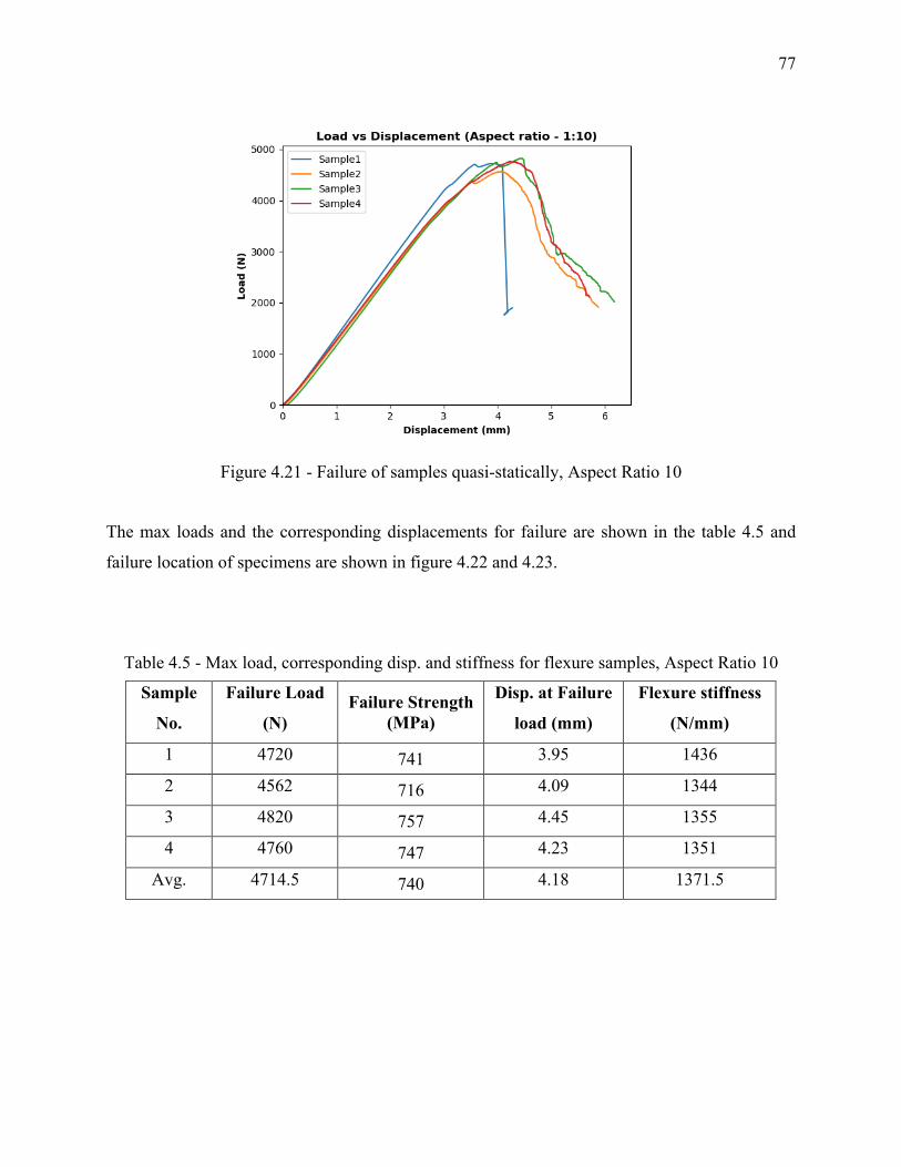
77
Figure 4.21 - Failure of samples quasi-statically, Aspect Ratio 10
The max loads and the corresponding displacements for failure are shown in the table 4.5 and
failure location of specimens are shown in figure 4.22 and 4.23.
Table 4.5 - Max load, corresponding disp. and stiffness for flexure samples, Aspect Ratio 10
Sample
No.
Failure Load
(N) Failure Strength
(MPa)
Disp. at Failure
load (mm)
Flexure stiffness
(N/mm)
1 4720 741 3.95 1436
2 4562 716 4.09 1344
3 4820 757 4.45 1355
4 4760 747 4.23 1351
Avg. 4714.5 740 4.18 1371.5
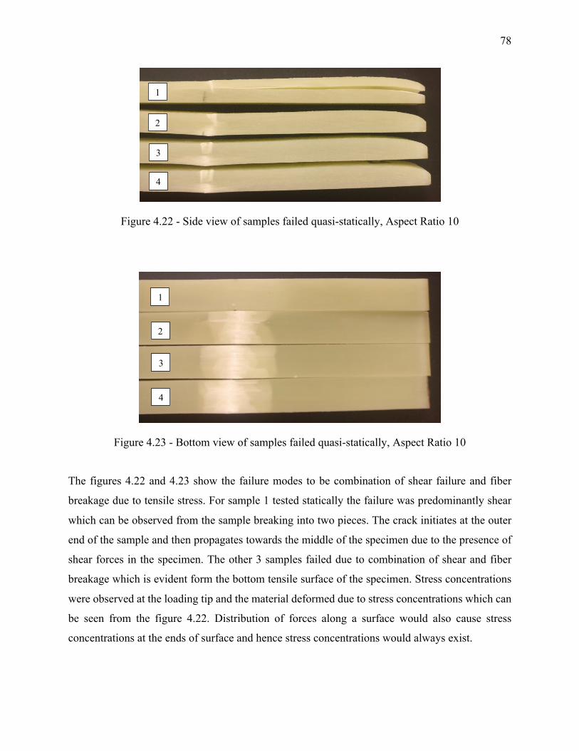
78
Figure 4.22 - Side view of samples failed quasi-statically, Aspect Ratio 10
Figure 4.23 - Bottom view of samples failed quasi-statically, Aspect Ratio 10
The figures 4.22 and 4.23 show the failure modes to be combination of shear failure and fiber
breakage due to tensile stress. For sample 1 tested statically the failure was predominantly shear
which can be observed from the sample breaking into two pieces. The crack initiates at the outer
end of the sample and then propagates towards the middle of the specimen due to the presence of
shear forces in the specimen. The other 3 samples failed due to combination of shear and fiber
breakage which is evident form the bottom tensile surface of the specimen. Stress concentrations
were observed at the loading tip and the material deformed due to stress concentrations which can
be seen from the figure 4.22. Distribution of forces along a surface would also cause stress
concentrations at the ends of surface and hence stress concentrations would always exist.
1
2
3
4
1
2
3
4
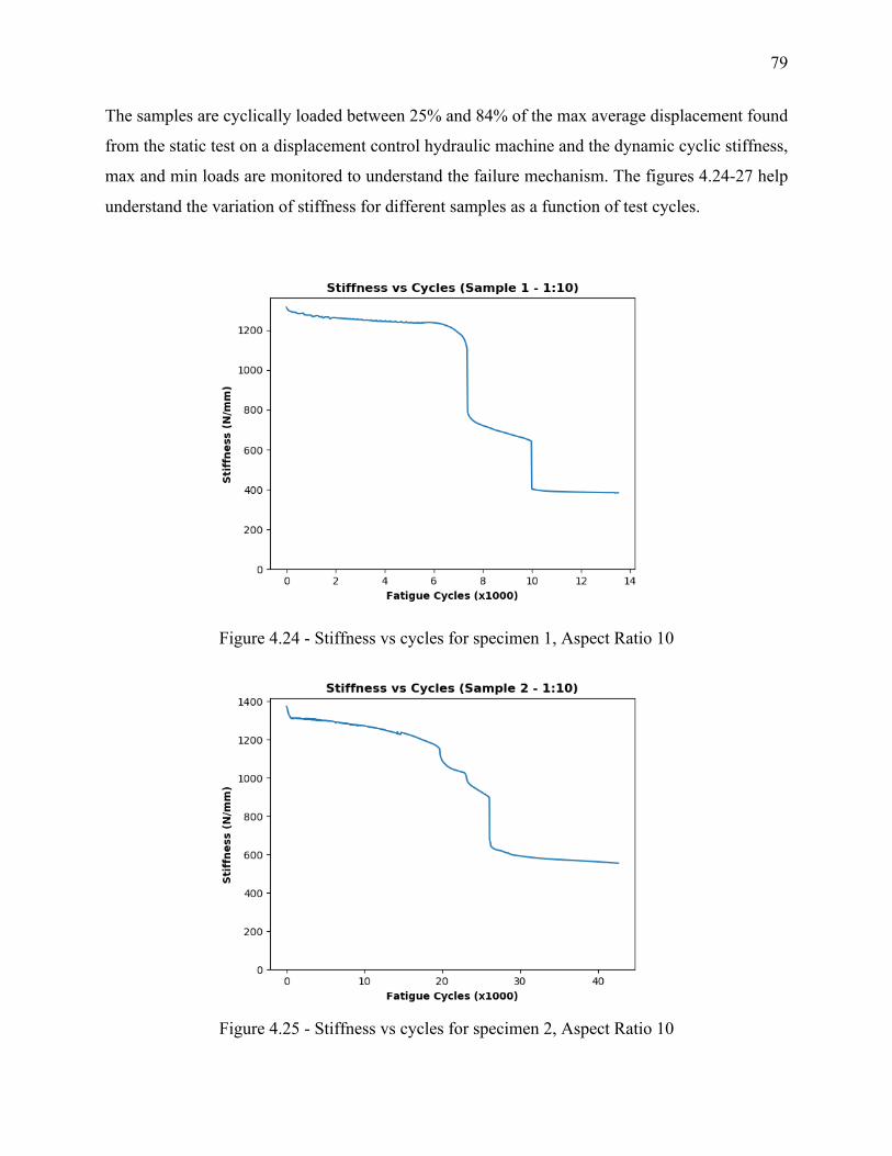
79
The samples are cyclically loaded between 25% and 84% of the max average displacement found
from the static test on a displacement control hydraulic machine and the dynamic cyclic stiffness,
max and min loads are monitored to understand the failure mechanism. The figures 4.24-27 help
understand the variation of stiffness for different samples as a function of test cycles.
Figure 4.24 - Stiffness vs cycles for specimen 1, Aspect Ratio 10
Figure 4.25 - Stiffness vs cycles for specimen 2, Aspect Ratio 10
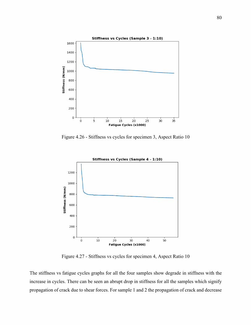
80
Figure 4.26 - Stiffness vs cycles for specimen 3, Aspect Ratio 10
Figure 4.27 - Stiffness vs cycles for specimen 4, Aspect Ratio 10
The stiffness vs fatigue cycles graphs for all the four samples show degrade in stiffness with the
increase in cycles. There can be seen an abrupt drop in stiffness for all the samples which signify
propagation of crack due to shear forces. For sample 1 and 2 the propagation of crack and decrease
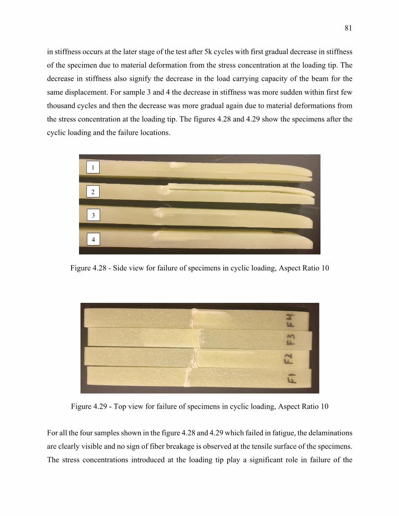
81
in stiffness occurs at the later stage of the test after 5k cycles with first gradual decrease in stiffness
of the specimen due to material deformation from the stress concentration at the loading tip. The
decrease in stiffness also signify the decrease in the load carrying capacity of the beam for the
same displacement. For sample 3 and 4 the decrease in stiffness was more sudden within first few
thousand cycles and then the decrease was more gradual again due to material deformations from
the stress concentration at the loading tip. The figures 4.28 and 4.29 show the specimens after the
cyclic loading and the failure locations.
Figure 4.28 - Side view for failure of specimens in cyclic loading, Aspect Ratio 10
Figure 4.29 - Top view for failure of specimens in cyclic loading, Aspect Ratio 10
For all the four samples shown in the figure 4.28 and 4.29 which failed in fatigue, the delaminations
are clearly visible and no sign of fiber breakage is observed at the tensile surface of the specimens.
The stress concentrations introduced at the loading tip play a significant role in failure of the
1
2
3
4
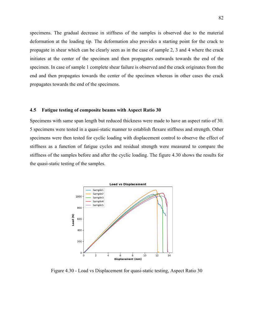
82
specimens. The gradual decrease in stiffness of the samples is observed due to the material
deformation at the loading tip. The deformation also provides a starting point for the crack to
propagate in shear which can be clearly seen as in the case of sample 2, 3 and 4 where the crack
initiates at the center of the specimen and then propagates outwards towards the end of the
specimen. In case of sample 1 complete shear failure is observed and the crack originates from the
end and then propagates towards the center of the specimen whereas in other cases the crack
propagates towards the end of the specimens.
Fatigue testing of composite beams with Aspect Ratio 30
Specimens with same span length but reduced thickness were made to have an aspect ratio of 30.
5 specimens were tested in a quasi-static manner to establish flexure stiffness and strength. Other
specimens were then tested for cyclic loading with displacement control to observe the effect of
stiffness as a function of fatigue cycles and residual strength were measured to compare the
stiffness of the samples before and after the cyclic loading. The figure 4.30 shows the results for
the quasi-static testing of the samples.
Figure 4.30 - Load vs Displacement for quasi-static testing, Aspect Ratio 30
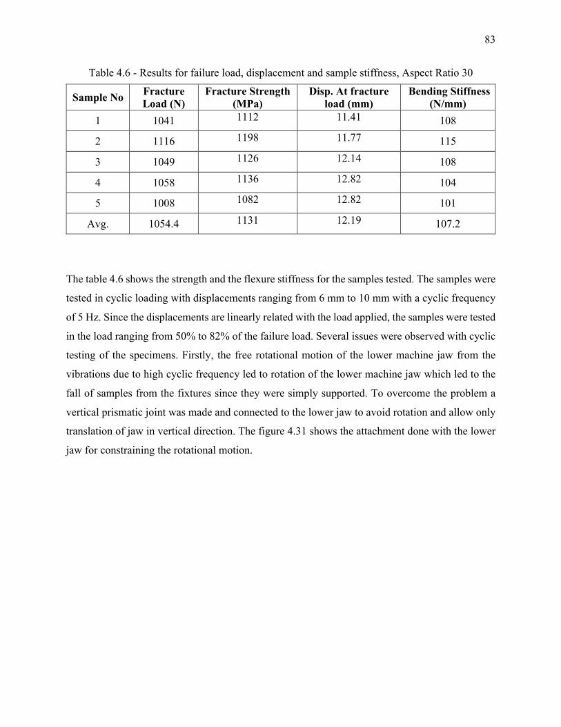
83
Table 4.6 - Results for failure load, displacement and sample stiffness, Aspect Ratio 30
Sample No Fracture Load (N)
Fracture Strength (MPa)
Disp. At fracture load (mm)
Bending Stiffness (N/mm)
1 1041 1112 11.41 108
2 1116 1198 11.77 115
3 1049 1126 12.14 108
4 1058 1136 12.82 104
5 1008 1082 12.82 101
Avg. 1054.4 1131 12.19 107.2
The table 4.6 shows the strength and the flexure stiffness for the samples tested. The samples were
tested in cyclic loading with displacements ranging from 6 mm to 10 mm with a cyclic frequency
of 5 Hz. Since the displacements are linearly related with the load applied, the samples were tested
in the load ranging from 50% to 82% of the failure load. Several issues were observed with cyclic
testing of the specimens. Firstly, the free rotational motion of the lower machine jaw from the
vibrations due to high cyclic frequency led to rotation of the lower machine jaw which led to the
fall of samples from the fixtures since they were simply supported. To overcome the problem a
vertical prismatic joint was made and connected to the lower jaw to avoid rotation and allow only
translation of jaw in vertical direction. The figure 4.31 shows the attachment done with the lower
jaw for constraining the rotational motion.
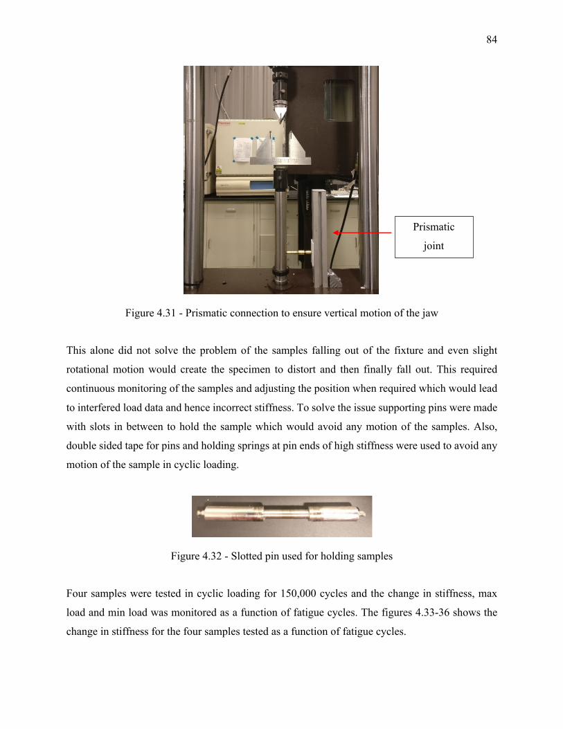
84
Figure 4.31 - Prismatic connection to ensure vertical motion of the jaw
This alone did not solve the problem of the samples falling out of the fixture and even slight
rotational motion would create the specimen to distort and then finally fall out. This required
continuous monitoring of the samples and adjusting the position when required which would lead
to interfered load data and hence incorrect stiffness. To solve the issue supporting pins were made
with slots in between to hold the sample which would avoid any motion of the samples. Also,
double sided tape for pins and holding springs at pin ends of high stiffness were used to avoid any
motion of the sample in cyclic loading.
Figure 4.32 - Slotted pin used for holding samples
Four samples were tested in cyclic loading for 150,000 cycles and the change in stiffness, max
load and min load was monitored as a function of fatigue cycles. The figures 4.33-36 shows the
change in stiffness for the four samples tested as a function of fatigue cycles.
Prismatic
joint
mechanism
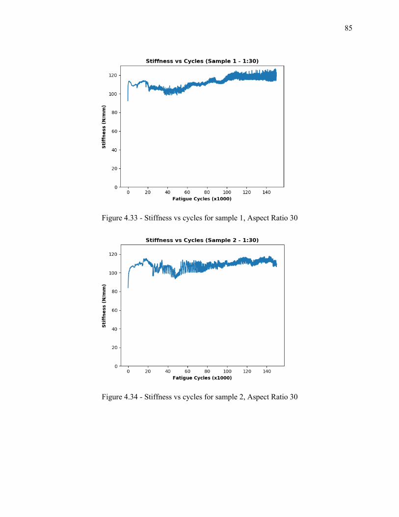
85
Figure 4.33 - Stiffness vs cycles for sample 1, Aspect Ratio 30
Figure 4.34 - Stiffness vs cycles for sample 2, Aspect Ratio 30
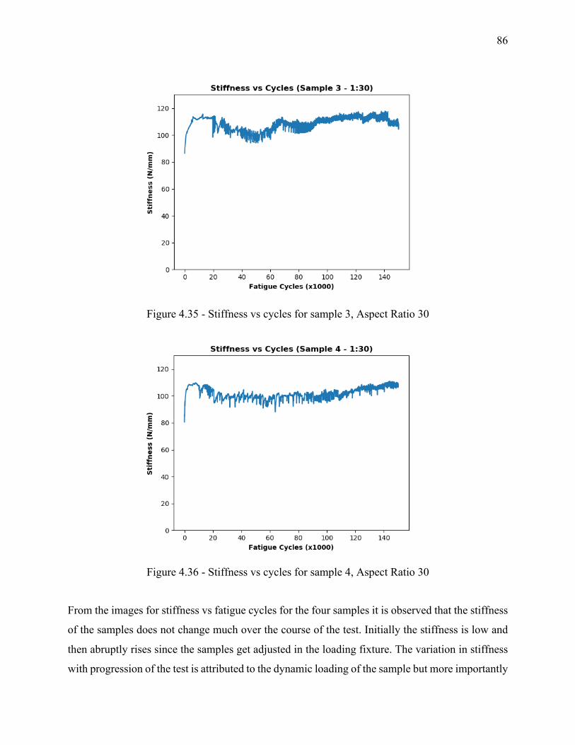
86
Figure 4.35 - Stiffness vs cycles for sample 3, Aspect Ratio 30
Figure 4.36 - Stiffness vs cycles for sample 4, Aspect Ratio 30
From the images for stiffness vs fatigue cycles for the four samples it is observed that the stiffness
of the samples does not change much over the course of the test. Initially the stiffness is low and
then abruptly rises since the samples get adjusted in the loading fixture. The variation in stiffness
with progression of the test is attributed to the dynamic loading of the sample but more importantly
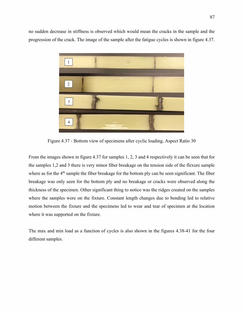
87
no sudden decrease in stiffness is observed which would mean the cracks in the sample and the
progression of the crack. The image of the sample after the fatigue cycles is shown in figure 4.37.
Figure 4.37 - Bottom view of specimens after cyclic loading, Aspect Ratio 30
From the images shown in figure 4.37 for samples 1, 2, 3 and 4 respectively it can be seen that for
the samples 1,2 and 3 there is very minor fiber breakage on the tension side of the flexure sample
where as for the 4th sample the fiber breakage for the bottom ply can be seen significant. The fiber
breakage was only seen for the bottom ply and no breakage or cracks were observed along the
thickness of the specimen. Other significant thing to notice was the ridges created on the samples
where the samples were on the fixture. Constant length changes due to bending led to relative
motion between the fixture and the specimens led to wear and tear of specimen at the location
where it was supported on the fixture.
The max and min load as a function of cycles is also shown in the figures 4.38-41 for the four
different samples.
1
2
3
4
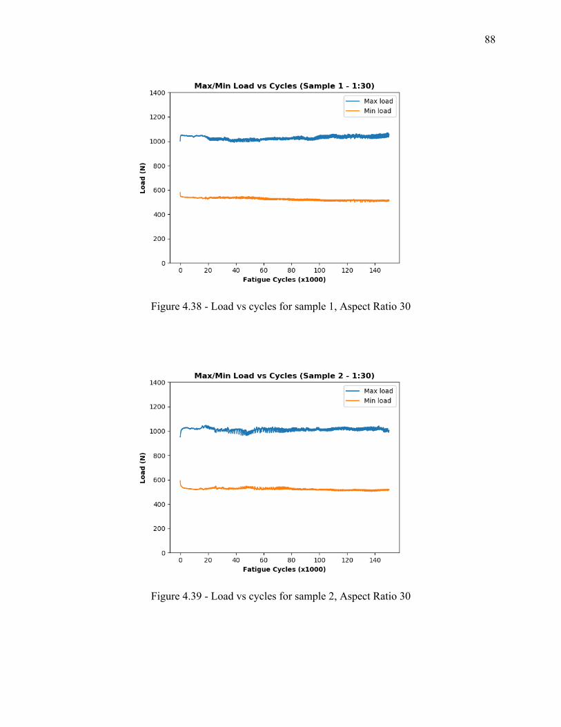
88
Figure 4.38 - Load vs cycles for sample 1, Aspect Ratio 30
Figure 4.39 - Load vs cycles for sample 2, Aspect Ratio 30
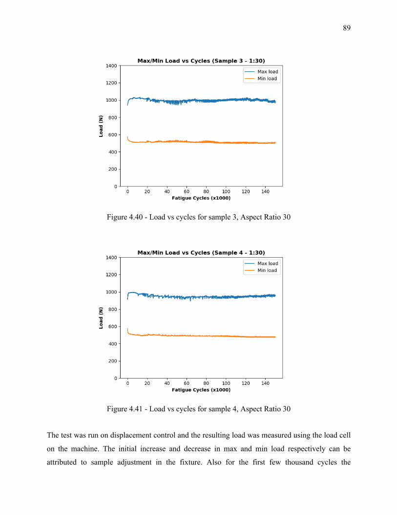
89
Figure 4.40 - Load vs cycles for sample 3, Aspect Ratio 30
Figure 4.41 - Load vs cycles for sample 4, Aspect Ratio 30
The test was run on displacement control and the resulting load was measured using the load cell
on the machine. The initial increase and decrease in max and min load respectively can be
attributed to sample adjustment in the fixture. Also for the first few thousand cycles the
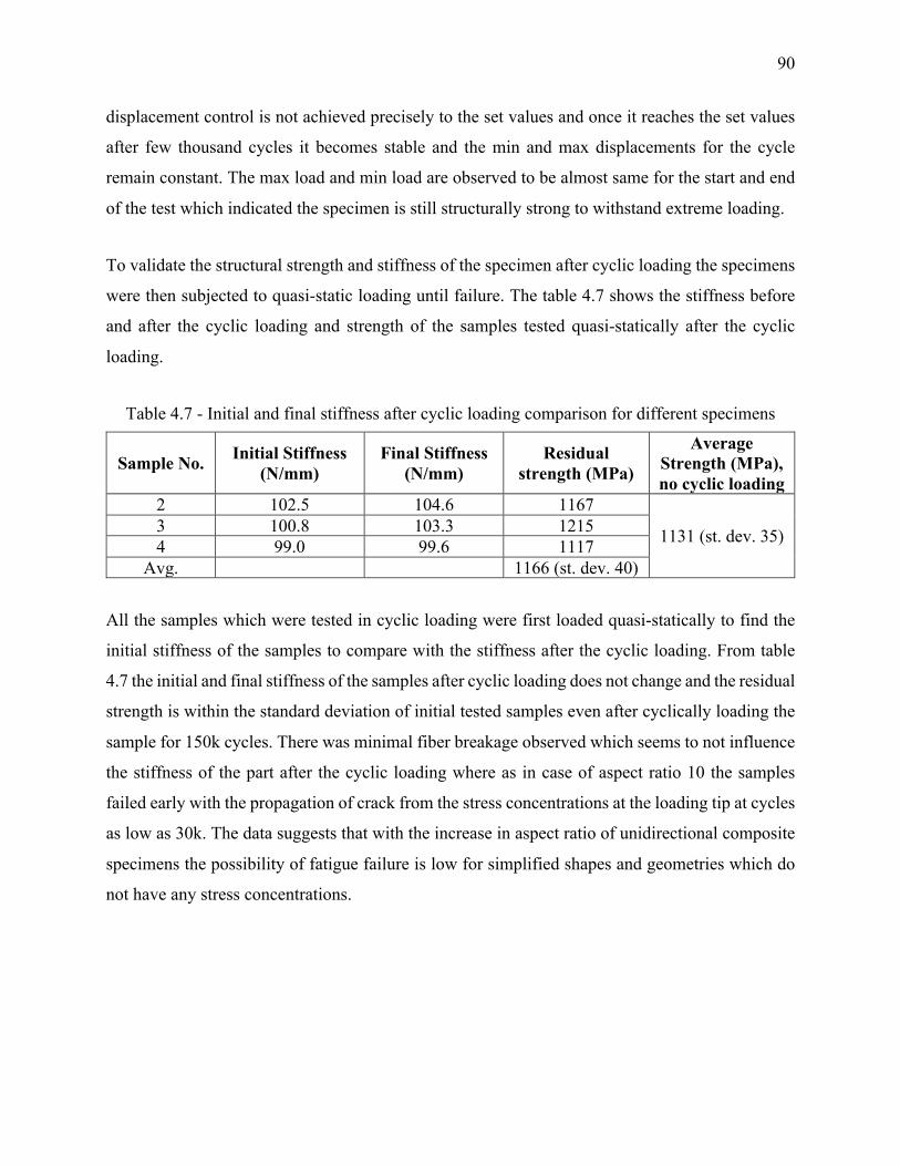
90
displacement control is not achieved precisely to the set values and once it reaches the set values
after few thousand cycles it becomes stable and the min and max displacements for the cycle
remain constant. The max load and min load are observed to be almost same for the start and end
of the test which indicated the specimen is still structurally strong to withstand extreme loading.
To validate the structural strength and stiffness of the specimen after cyclic loading the specimens
were then subjected to quasi-static loading until failure. The table 4.7 shows the stiffness before
and after the cyclic loading and strength of the samples tested quasi-statically after the cyclic
loading.
Table 4.7 - Initial and final stiffness after cyclic loading comparison for different specimens
Sample No. Initial Stiffness (N/mm)
Final Stiffness (N/mm)
Residual strength (MPa)
Average Strength (MPa), no cyclic loading
2 102.5 104.6 1167
1131 (st. dev. 35) 3 100.8 103.3 1215 4 99.0 99.6 1117
Avg. 1166 (st. dev. 40)
All the samples which were tested in cyclic loading were first loaded quasi-statically to find the
initial stiffness of the samples to compare with the stiffness after the cyclic loading. From table
4.7 the initial and final stiffness of the samples after cyclic loading does not change and the residual
strength is within the standard deviation of initial tested samples even after cyclically loading the
sample for 150k cycles. There was minimal fiber breakage observed which seems to not influence
the stiffness of the part after the cyclic loading where as in case of aspect ratio 10 the samples
failed early with the propagation of crack from the stress concentrations at the loading tip at cycles
as low as 30k. The data suggests that with the increase in aspect ratio of unidirectional composite
specimens the possibility of fatigue failure is low for simplified shapes and geometries which do
not have any stress concentrations.
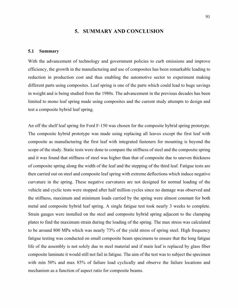
91
5. SUMMARY AND CONCLUSION
Summary
With the advancement of technology and government policies to curb emissions and improve
efficiency, the growth in the manufacturing and use of composites has been remarkable leading to
reduction in production cost and thus enabling the automotive sector to experiment making
different parts using composites. Leaf spring is one of the parts which could lead to huge savings
in weight and is being studied from the 1980s. The advancement in the previous decades has been
limited to mono leaf spring made using composites and the current study attempts to design and
test a composite hybrid leaf spring.
An off the shelf leaf spring for Ford F-150 was chosen for the composite hybrid spring prototype.
The composite hybrid prototype was made using replacing all leaves except the first leaf with
composite as manufacturing the first leaf with integrated fasteners for mounting is beyond the
scope of the study. Static tests were done to compare the stiffness of steel and the composite spring
and it was found that stiffness of steel was higher than that of composite due to uneven thickness
of composite spring along the width of the leaf and the stepping of the third leaf. Fatigue tests are
then carried out on steel and composite leaf spring with extreme deflections which induce negative
curvature in the spring. These negative curvatures are not designed for normal loading of the
vehicle and cyclic tests were stopped after half million cycles since no damage was observed and
the stiffness, maximum and minimum loads carried by the spring were almost constant for both
metal and composite hybrid leaf spring. A single fatigue test took nearly 3 weeks to complete.
Strain gauges were installed on the steel and composite hybrid spring adjacent to the clamping
plates to find the maximum strain during the loading of the spring. The max stress was calculated
to be around 800 MPa which was nearly 73% of the yield stress of spring steel. High frequency
fatigue testing was conducted on small composite beam specimens to ensure that the long fatigue
life of the assembly is not solely due to steel material and if main leaf is replaced by glass fiber
composite laminate it would still not fail in fatigue. The aim of the test was to subject the specimen
with min 50% and max 85% of failure load cyclically and observe the failure locations and
mechanism as a function of aspect ratio for composite beams.
92
Aspect ratio of 10 and 30 were chosen for the fatigue test of composite beams. The samples were
first subjected to quasi-static test to find failure stress and then tested in cyclic conditions. For the
samples with aspect ratio 10 it was found that the samples failed in combination of shear and
bending stress in cyclic loading. Stress concentrations at the loading tip led to material deformation
which then lead to initiation site for crack propagation due to shear. The samples failed at an early
stage of cyclic loading at around 5k cycles. Abrupt drop in stiffness was observed which was from
crack propagation due to shear forces. Samples with aspect ratio of 30 were subjected to same tests
but the number of test cycles were limited to 150k to shorten the duration of the test as the samples
did not fail under the same displacement conditions. Flexure stiffness of the composite beams was
measured before and after the test and no drop was observed in bending stiffness of the samples
after cyclic loading of 150k cycles. Residual strength of the beams was also measured after cyclic
loading and compared with the strength of the specimens tested quasi-statically to failure without
cyclic loading. The residual strength was found to be within the standard deviation of the strengths
of the initially tested specimens without cyclic loading indicating no drop in the strength after
cyclic loading of specimens.
Conclusion
The fatigue testing of samples with aspect ratio 10 and 30 give an insight into failure locations and
mechanism. The results for cyclic loading of samples with aspect ratio 30 indicate that with high
enough aspect ratio to neglect shear forces and without the presence of stress concentrations the
probability of failure of composite structures in fatigue is low in flexure. Extending the same
analogy to leaf springs made using composites it can be concluded that keeping a large enough
aspect ratio to neglect shear forces with no stress concentrations chances of failure due to fatigue
loading are low and leaf springs can be successfully used for automotive applications.
93
REFRENCES
[1] “https://www.rsc.org/Education/Teachers/Resources/Inspirational/Resources/4.3.1.pdf”
[2] “Thermoset vs. Thermoplastics,” Modor Plastics. .
[3] “Thermoplastics vs Thermosetting Plastics | Recycled Plastic.”: http://www.recycledplastic.com/index.html%3Fp=10288.html.
[4] “Fabrication methods.”: https://www.compositesworld.com/ariticles/fabrication-methods.
[5] C. H. Park and W. I. Lee, “3 - Compression molding in polymer matrix composites,” in Manufacturing Techniques for Polymer Matrix Composites (PMCs), S. G. Advani and K.-T. Hsiao, Eds. Woodhead Publishing, 2012, pp. 47–94.
[6] “LEAF SPRING vs. TORSION: HOW NOT TO GET WRAPPED AROUND THE AXLE » Grandville Trailer Blog,” Grandville Trailer Blog, 02-Dec-2016. .
[7] “http://www.bamgarage.com/gallery/kun-toyota-hilux-suspension-repair-fixing-a-foreign-suspension-kit-after-only-12months-in-use/"
[8] “Overslung or Underslung Trailer Springs?,” Mechanical Elements, 09-Jan-2019. .
[9] B. E. Kirkham, L. S. Sullivan, and R. E. Bauerle, “Development of the Liteflex tm Suspension Leaf Spring,” SAE Transactions, vol. 91, pp. 663–673, 1982.
[10] K. Tanabe, T. Seino, and Y. Kajio, “Characteristics of Carbon/Glass Fiber Reinforced Plastic Leaf Spring,” SAE Transactions, vol. 91, pp. 1628–1636, 1982.
[11] T. N. Trebilcock and J. N. Epel, “Light Truck FRP Leaf Spring Development,” presented at the SAE International Congress and Exposition, 1981, p. 810325.
[12] M. Soner et al., “Design and Fatigue Life Comparison of Steel and Composite Leaf Spring,” presented at the SAE 2012 World Congress & Exhibition, 2012, pp. 2012-01–0944.
[13] I. Rajendran and S. Vijayarangan, “Optimal design of a composite leaf spring using genetic algorithms,” Computers & Structures, vol. 79, no. 11, pp. 1121–1129, Apr. 2001.
[14] H. Banka, R. Muluka, and V. Reddy, “Fabrication and Experimental Analysis of Epoxy-Glass Fiber Composite Leaf Spring,” presented at the International Conference on Advances in Design, Materials, Manufacturing and Surface Engineering for Mobility, 2017, pp. 2017-28–1985.
[15] H. A. Al-Qureshi, “Automobile leaf springs from composite materials,” Journal of Materials Processing Technology, vol. 118, no. 1, pp. 58–61, Dec. 2001.
94
[16] W. J. Yu and H. C. Kim, “Double tapered FRP beam for automotive suspension leaf spring,” Composite Structures, vol. 9, no. 4, pp. 279–300, Jan. 1988.
[17] C. J. Morris, “Composite integrated rear suspension,” Composite Structures, vol. 5, no. 3, pp. 233–242, Jan. 1986.
[18] “Composite leaf springs: Saving weight in production.”: https://www.compositesworld.com/ariticles/composite-leaf-springs-saving-weight-in-production-suspension-systems.
[19] “500,000 parts per year? No problem!”: https://www.compositesworld.com/blog/post/500000-parts-per-year-no-problem-.
[20] “Volvo XC90 features polyurethane composite leaf spring,” Materials Today. [Online]. Available: https://www.materialstoday.com/composite-applications/news/volvo-xc90-features-polyurethane-composite-leaf/.
[21] IMG Sachsen-Anhalt, IFC Composite GmbH (en). .
[22] S. of A. E. S. Committee, Spring Design Manual. Society of Automotive Engineers, 1996.
[23] R. G. Budynas and J. K. Nisbett, Shigley’s mechanical engineering design, 9th ed. New York: McGraw-Hill, 2011.
Related Documents