MANUFACTURING & INSTALLATION GUIDELINES & GUIDE SPECIFICATIONS for STRUCTURAL PRECAST www.FabconPrecast.com CONTENTS: 2 Manufacturing Tolerances 4 Installation Tolerances 5 Definitions

Welcome message from author
This document is posted to help you gain knowledge. Please leave a comment to let me know what you think about it! Share it to your friends and learn new things together.
Transcript

MANUFACTURING & INSTALLATION
GUIDELINES & GUIDE SPECIFICATIONSfor STRUCTURAL
PRECASTwww.FabconPrecast.com
CONTENTS:2 Manufacturing Tolerances4 Installation Tolerances5 Definitions

FABCONPRECAST.COM 1
FABCON DESIGN GUIDELINES FOR PRECAST CONCRETE WALL PANELS
Fabcon is committed to construction innovation and safety. Through continuous
improvement in quality and efficiency, Fabcon delivers high quality products and
services of exceptional value. This document provides guidelines for designing precast
concrete wall panels to Fabcon’s manufacturing and installation tolerances. Based
heavily on the quality control manual for precast and prestressed concrete plants
published by the Precast/Prestressed Concrete Institute (PCI) MNL 116, these
tolerances reflect Fabcon’s unique manufacturing processes and patented products.
As a designer, manufacturer and installer of precast products, Fabcon delivers a
complete wall panel system. These tolerances represent our acceptable manufacturing
and installation guidelines. They do not represent an exhaustive criteria for rejection.
These guidelines are intended as a reference for licensed designers and construction
professionals. Nothing in these guidelines shall relieve the designer of record from
responsibility for the structure’s design and proper interface of the precast panel
system with the building structure. Fabcon is not responsible for deficiencies in building
design.
REMEDIES - Fabcon may elect one or more of the following solutions:
- Bring the product into tolerance by industry-standard repair methods.
- Provide calculations that demonstrate that the product/installation meets acceptable structural and
architectural performance criteria.
- Demonstrate that the completed systems meets acceptable structural and architectural requirements or
offer modifications to meet design requirements.
Due to the inherent nature of concrete, hydration, handling, and shipping of precast,
some chipping and or cracking may occur. Product may require routine finishing such
as blending for texture and color after installation. Fabcon bases our scope of work on
a completed wall panel system and specifically excludes project specifications granting
the unilateral right to reject product that is correctable utilizing standard industry
repair methods or can be demonstrated to meet structural and/or architectural
performance criteria.

VersaCore+Green WALL PANEL MANUFACTURING TOLERANCES
ü
ü
N/A
ü
N/A
N/A
ü
ü
ü
ü
FABCON MNL116
k2 = LOCATION OF STRAND Parallel to Plane of Panel
................................................................± ½" [± 13mm]
l1 = LOCATION of Embedment..................± 1" [± 13mm]
l2 = TIPPING and Flushness of Embedment
..................................................................± ¼" [± 6mm]
l3 = CONCRETE Surface Between Embedments toReceive Continuous Ledger, Relative to Plane ofEmbedments ............................................. - ¼", + 0" [- 6mm, + 0mm]
n1 = LOCATION of Blockouts.....................± 1" [± 25mm]
n2 = SIZE of Blockout..............................± ½" [± 13mm]
p = LOCATION of Inserts for Structural Connections
...............................................................± 1" [± 25mm]*
*for further details contact your Sales Engineer
t1 = SIZE of Architectural Feature.............± ¼" [± 6mm]
t2 = LOCATION of Architectural Feature..................................................................± ¼" [± 6mm]
x = WEIGHT....................Actual measured value shall notexceed 110 percent of the nominal published unit weight used in the design.
i = BOW..........................................Length/360 maximum
i1 = DIFFERENTIAL BOWING Between Adjacent Panels of the Same Design ................................................................± ½" [± 13mm]
j = WARP.............± 1/16" per foot [± 1.5mm per 300mm]
± 1”
ü
ü
ü
ü
ü
± ½"
± ⅛"
± ⅛”
ü
ü
ü
ü
FABCON MNL116
a = LENGTH..........................................± ½" [± 13mm]
b = WIDTH (overall)................................± ¼" [± 6mm]
b1 = WEB WIDTH
The total web width defined by the sum of the actual measured values of “b1” shall not be less than 85 percent of the sum of the nominal web widths “b1 nominal”
c = DEPTH (overall)...............................± ¼" [± 6mm]
c1 = TOP FLANGE DEPTH
Top flange area defined by the actual measured values of average “c1” x “b” shall not average less than 85 percent of the nominal area calculated by “c1 nominal” x ” “b nominal”.............................................................≥ ¾" [≥ 18mm]
c2 = BOTTOM FLANGE DEPTH Bottom flange area defined by the actual measured values of average “c2” x “b” shall not be less than 85 percent of the nominal area calculated by “c2 nominal” x “b nominal”
..............................................................≥ ¾" [≥ 18mm]
d = VARIATION from Specified Plan End Squareness of Skew............................± ⅛" per 12" width, ± ½" maximum...........[± 3mm per 300 mm width, ± 13mm maximum]
e = VARIATION from Specified Elevation End Squareness or Skew...............................± ⅛" per 12" [± 3mm per 300 mm]
f = SWEEP.......................................± ⅛" per 20", ±⅜" maximum ............................[± 3mm per 6m, ± 10 mm maximum]
k1 = LOCATION OF STRAND Perpendicular to Plane of
Panel...............................................................± ¼" [± 6mm]
Concrete is a variable material. Even after final finishing, there will be a range of color and texture in the surface. Some variations are to be expected.
Tolerances shown should be considered as guidelines for an acceptable range and not limits for rejection. If these tolerances are met, the unit should be accepted. If these tolerances are exceeded, the unit may still be acceptable if it meets any of the following criteria:
1. Exceeding the tolerance does not affect the structural integrity of the unit. 2. The unit can be brought within tolerance by structurally satisfactory means. 3. The total erected assembly can be modified to meet all structural requirements.
2 FABCONPRECAST.COM
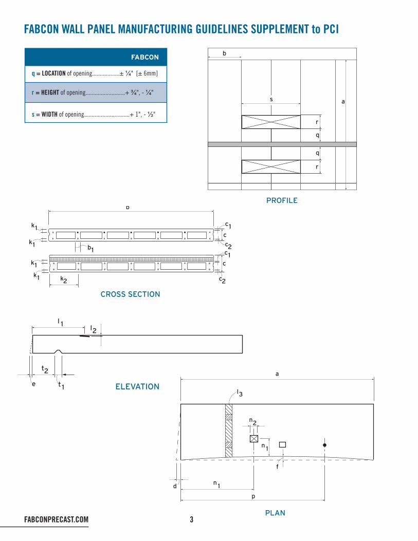
FABCON WALL PANEL MANUFACTURING GUIDELINES SUPPLEMENT to PCI
q = LOCATION of opening..................± ¼" [± 6mm]
r = HEIGHT of opening..........................+ ¾", - ¼"
s = WIDTH of opening..............................+ 1", - ½"
FABCON
CROSS SECTION
b
b1
k1
k1
k1
k1 k2
c1c
c2c1
c
c2
PLAN
l3
a
n2
f
p
n 1d
n 1
ELEVATION
l 1l2
t2
e t 1
PROFILE
b
s
r
r
q
q
a
FABCONPRECAST.COM 3

4 FABCONPRECAST.COM
a = Plan location from building grid datum.................. ± ½" ü
a1 = Plan location from centerline of steel support........ ± ½" ü
b = Top elevation from nominal top elevation;
Exposed individual panel........................................ ± ½" ü
Non-exposed individual panel.................................± ¾" ü
Exposed relative to adjacent panel......................... ± ½" ü
Non-exposed relative to adjacent panel..................± ¾" ü
c = Support elevation from nominal elevation:
Maximum low.............................................................. ½" ü
Maximum high............................................................ ¼" ü
d = Maximum plumb variation over height of structure or over 100 ft. whichever is less*.............. ± 1" ü *For precast buildings in excess of 100' tall tolerances “a” and “d” can increase at a rate of ⅛" (3mm) per story to a maximum 2" (50mm).
e = Plumb in any 10 ft. of element height.....................± ¼" ü
f = Maximum jog in alignment of matching edges....... ± ½" ü
g = Joint width (governs over joint taper)......................± ⅜" ü
g1 = Form Side.................................................½" ± ⅜" N/A g2 = Top Face Side............................................ ¾" ± ⅜" N/A g3 = Top Face Side............................................ ⅞" ± ⅜" N/A
h = Joint taper over height.............................................± ¾" ½”
h10 = Joint taper over 10 ft. height................................... ± ⅜" ü
i = Maximum jog in alignment of matching faces:
Exposed to view....................................................... ± ⅜" ü
Not exposed to view................................................. ± ¾" ü
j = Differential bowing or camber as erected between adjacent members of the same design................... ± ½" ü
FABCON MNL135
VersaCore+Green WALL PANEL FIELD INSTALLATION TOLERANCES
PLAN
Buildinggrid datuma
ai
a of Steelstructure
Steelstructure
1
SECTION
d d
b
e e
c
10’-
0”
Footing Buildingelevationdatum
NOMINAL JOINTWIDTH ELEVATION
f h
h10
10’-
0”
g
TYPICAL PANEL JOINT
= NOMINAL, 1/8” to 7/8”inclusive of tolerances
Chamfered edgefrom pallet
Formed sideof panel
Top, tooledside of panel
Rounded edgesfrom tooling
Caulking may lookslightly wider due to radiused, chamferedor tooled edges.
g1
g2
= NOMINAL, 1/8” to 7/8”inclusive of tolerances
Chamfered edgesfrom pallet
Formed sideof panel
Top, tooledside of panel
Rounded edgesfrom tooling
Caulking may lookslightly wider due to radiused, chamferedor tooled edges.
TYPICAL PANEL JOINT
g1
The recommended erection tolerance values are those to which the member primary control surfaces are to be set. It is the position dimensions of the primary erection control surfaces which should be controlled during erection. Theremaining position dimensions of the member features and secondary control surfaces of the member will be the result of the combination of the erection tolerances and the appropriate product tolerances. Erection and product tolerances for some features of a precast concrete member may be additive.

FABCONPRECAST.COM 5
DEFINITIONS
CAMBER – The deflection that occurs in prestressed concrete members due to the net bending resulting from the eccentricity of the prestress force.
CLEARANCE – Interface space (distance) between two elements. Clearance is normally specified to allow for the effects of product and erection tolerances and for anticipated movement (e.g. deflection, thermal movement).
COVER – The least distance between the surface of the reinforcement and the surface approxi-mates a plane.
FLATNESS – The degree to which a surface approximates a plane.
HARPED (DEFLECTED) STRAND – The path ofa prestressing strand in a member may be altered from the horizontal to increase load carrying capacity or to control member stresses, or both. This practice is referred to as harping, deflecting or depressing the strand.
SMOOTHNESS – Due to Fabcon’s uniquemanufacturing process normal PCI “smoothness” tolerances do not apply. Consult your Fabcon engineer for finish specific tolerances.
SWEEP – A variation in horizontal alignment from a straight line parallel to centerline of member (horizontal bowing).
TOLERANCE – Permissible variation from speci-fied requirements.
BOWING – An overall our-of-plane curvature of a surface whose edges remain parallel.
WARPING – The twisting of a member resulting in an overall out-of-plane curvature of surfaces, characterized by non-parallel edges.
CROSS SECTIONCONVEX BOWING
CROSS SECTIONCONCAVE BOWING
Length of bowExposed face
Length of bow
Max. bowing (j)Max. bowing (j)
PANEL BOWED in BOTHELEVATION and CROSS SECTION
len
gth
of
bow
Exposedface (convex)
Exposedface (concave)
Max.bowing (j)
Precastconcretepanel
Bowing (l)(elevation)
Lengthof bow(elevation)
Bowing(cross section)
Length of bow(cross section)
True plane
Distance to farthest adjacent corner
Distan
ce to
nea
rest
adja
cent
corn
er

6 FABCONPRECAST.COM
PLANT - PRECAST STRUCTURAL CONCRETE PANELS
PART 1 - GENERAL
1.1 SUMMARY
A. Section includes:
1. Precast, prestressed, insulated structural concrete panels.
B. Related work specified elsewhere:
Section 03 3000 – Cast-in-place concrete. Section 05 1200 – Structural steel framing. Section 05 5000 – Metal fabrications. Section 07 6200 – Sheet metal flashing and trim. Section 07 9200 – Joint sealants: Perimeter joints with sealant and backing. Section 09 9000 – Painting and coating: Preparation of concrete surfaces beyond specified level of concrete finish required prior to painting.
C. Work furnished and installed by others:
1. Receivers or Reglets for flashing .
2. Elevator guides.
3. Steel required for bar joist bearing unless otherwise noted.
4. Deck angle, if required .
5. All loose steel and connections for beams where they attach to precast unless otherwise noted.
6. Hollow core plank, support steel, all connection steel, caulk and connections between precast wall panels and hollow core plank unless otherwise noted.
7. Any steel frames at openings. Not required for structural reasons. If needed for aesthetics, to be furnished and installed by others.
8. Caulk between precast wall panels and adjacent materials.

FABCONPRECAST.COM 7
1.2 REFERENCES
A. The publications listed below form a part of this specification to the extent referenced. Applicable sections of these publications are referenced within the text.
B. AWS – American Welding Society
ASTM – ASTM International
PCI – Precast/Prestressed Concrete Institute.
ACI – American Concrete Institute
1.3 SUBMITTALS
A. Submittal procedures: Submit all submittals electronically in PDF format via email, unless other wise specified.
B. Shop drawings:
1. Plans, elevations, and details indicating panel locations, design loads, construction (including welding requirements, finish, and openings etc.), identify product provided by the manufacturer.
2. Shop drawings shall be signed and sealed by a professional engineer licensed in the jurisdiction in which the project is located.
C. Product design criteria: Design calculations shall be performed by an engineer experienced in precast, prestressed concrete design. Design calculations, signed by a professional engineer licensed in the jurisdiction in which the project is located, shall be submitted upon request. Information shall include:
1. Dead, live, wind, and seismic loads as identified in contract documents and as required by applicable codes.
2. Temporary bracing loads if required

8 FABCONPRECAST.COM
D. Test reports: Test reports on concrete and other materials used in fabrication. Submittal is not required unless specifically requested, reports to be maintained reports on file with the manufacturer and available upon request.
1.4 QUALITY ASSURANCE
A. Manufacturer’s qualifications: The manufacturer’s precast concrete production facility shall be certified by PCI Plant Certification Program. Manufacturer shall have produced product similar to what is specified for a minimum of two years.
B. Erector’s qualifications:
1. Regularly engaged for a minimum of five years in the erection of precast structural concrete similar to the requirements of this project.
2. Erection crews shall be certified by PCI Field Certification Program prior to start of precast installation.
C. Welders’ qualifications:
1. In accordance with AWS D1.1/1.1M and D1.4/1.4M.
1.5 DELIVERY, STORAGE, AND HANDLING
A. Transport, handle, store, and protect products in compliance with manufacturer’s recommendations.
B. Support panels during shipment on shock-absorbing material.
C. Store units with adequate bracing and protect units to prevent contact with soil, to prevent staining, and to prevent cracking, distortion, warping or other physical damage.
1. Store units with dunnage across full width of each bearing point unless otherwise indicated.
2. Place adequate dunnage of even thickness between each unit.
3. Place stored units so identification marks are clearly visible and units can be inspected.
D. Handle and transport units in a position consistent with their shape and design.
E. Lift and support units only at designated points shown on shop drawings and/or per manufacturer’s recommendations.

FABCONPRECAST.COM 9
PART 2 - PRODUCTS
2.1 PRECAST CONCRETE WALL PANEL MANUFACTURER
A. Fabcon: Savage, MN; Pleasanton, KS; Grove City, OH; and Mahanoy City, PA.
2.2 WALL PANELS
A. Precast, prestressed insulated sandwich wall panels and/or VersaCore+Green by Fabcon, as indicated on drawings.
2.3 DESIGN CRITERIA AND REGULATORY REQUIREMENTS
A. Comply with the design recommendations in PCI MNL 120. Comply with applicable building codes.
B. Calculated Fire-Test-Response characteristics: provide precast concrete units with fire-resistance rating indicated as calculated according to PCI MNL 124 and acceptable to authorities having jurisdiction.
2.4 MATERIALS
A. Portland Cement: ASTM C 150.
B. Admixtures: 1. Air-entraining admixtures: ASTM C 260.
2. Water reducing, retarding, accelerating, high-range water reducing admixtures: ASTM C 494.
3. Fly ash as required by the manufacturer.
C. Aggregates: ASTM C 33 or C 330.
D. Water: Potable and free of foreign materials in amounts harmful to concrete, aggregate, or embedded steel.

10 FABCONPRECAST.COM
E. Steel reinforcing:
1. Reinforcing bars: deformed billet steel: ASTM A 615, deformed rail steel ASTM A616, deformed axle steel ASTM A617, deformed low alloy steel ASTM A706.
2. Wire: cold-drawn steel: ASTM A 82.
3. Wire fabric:
a. Welded steel: ASTM A 185.
b. Welded deformed steel: ASTM A 497.
F. Strand: Uncoated, 7-wire, stress relieved or low relaxation steel strand: ASTM A 416 (including supplement) Grade 250K or 270K.
G. Anchors and inserts: Structural steel, ASTM A 36, manufacturer’s standard finish.
H. Wythe connectors: Polypropylene.
I. Rigid insulation: Expanded polystyrene board insulation and expanded polystyrene billets.
J. Bearing pads: High density plastic or hardboard shims or combination of both as recommended by precast concrete fabricator.
K. Sand-cement grout:
1. Portland Cement: ASTM C 150, Type I.
2. Clean, natural sand: ASTM C 144 or ASTM C 404.
L. Joint sealant: Sikaflex 2c NS by Sika Corporation, (800) 933-7452 or (201) 933-8800.
1. Color selection to be from manufacturer’s standard palette and matched to adjacent precast concrete wall panel color, unless selected/approved by owner’s representative.
2.5 CONCRETE MIXES
A. Mix design for the project, to provide concrete with the following properties:
1. Compressive strength: 7000 psi min. at 28 days.
2. Release strength: 3500 psi min.
3. Calcium chloride, chloride ions, and/or other salts are not permitted.

4. Entrained air: 4 percent min. entrained air concrete at exposed surfaces. 9.5 percent +/- 1.5 percent on structural portion of panels.
2.6 GROUT MIXES
A. Portland Cement and sand with minimum water required for placement and hydration.
2.7 FABRICATION
A. Manufacturing procedures shall be in general compliance with PCI MNL 116.
B. Manufacturing tolerances shall generally comply with PCI plant certification for structural products.
C. Finishes: In general, finishes will comply with Grade B per PCI MNL 116, 4th addition, Appendix C
1. Standard underside: (Formed Finish).
a. Provide finish produced by casting against approved forms using good industry practice in cleaning forms, design of concrete mix, placing and curing.
b. Small surface holes caused by air bubbles, normal color variation, normal form joints, minor chips and spalls shall be tolerated. No major or unsightly imperfections, honeycombs or other defects shall be permitted unless they are nonstructural in nature and are patched per industry standards.
2. Standard top: (Exposed Unformed Surface finish):
a. Extent of finishes as indicated on the drawings.
b. Provide finish resulting from vibratory screed and additional hand finishing.
c. Normal color variation, minor indentations, minor chips and spalls shall be permitted. No major imperfections, honeycombs or defects shall be permitted unless they are nonstructural in nature and are patched per industry standards.
d. Colors: per design requirements
D. Openings:
1. Openings may be plant cast or sawn (either in plant or field). Plant fabricate openings 12 inches round or square and larger as indicated on the approved shop drawings. Openings included at the time of manufacture will have a minimum of 3” of solid concrete at the perimeter. In cases where the insulation extends to the opening, window/door frames for insulated panels must be of sufficient width to cover insulation and allow anchorage into FABCONPRECAST.COM 11

the structural portion. Openings smaller than 12 inches are to be field cut by the trade requiring the opening after the precast, prestressed products have been erected. All openings shall be approved by the architect/engineer and the precast manufacturer before drilling or cutting.
2. For insulated panels, to minimize the risk of leaks, full depth head flashing is required at all openings. Penetrating the head flashing or failure to follow this detail may result in leaks, which are not the responsibility of the manufacturer.
E. Patching:
1. Maintain structural integrity.
2. Conform to panel fabricator’s recommendations and directions.
F. Fasteners: Cast in structural inserts, bolts, and plates as indicated on shop drawings.
G. Insulation: Place full length of panel and space across panel width between reinforcing strands.
H. Identify pickup points of precast structural concrete units and orientation in structure with permanent markings, complying with markings indicated on shop drawings. Imprint or permanently mark casting date on each precast structural concrete unit on a surface that will not show in finished structure.
I. Cure concrete according to requirements in PCI MNL 116 by moisture retention without heat or by accelerated heat curing using low-pressure live steam or radiant heat and moisture. Cure units until compressive strength is high enough to ensure that stripping does not have an effect on performance or appearance of final product.
2.8 SOURCE QUALITY CONTROL
A. Quality-control testing: In general compliance with testing provisions in PCI MNL 116, Manual for Quality Control for Plants and Production of Precast, Prestressed Concrete Products. Testing will be performed by manufacturer’s qualified personnel at the production facility.
PART 3 - EXECUTION
3.1 PREPARATION - Responsibilities of the General Contractor (GC) and/or Construction Manager (CM)
A. Provide suitable access to and around building with proper drainage and firm, level bearing for hauling and erection equipment. Provide a stable, compacted, and drainable 40-foot wide all-weather aggregate
12 FABCONPRECAST.COM

surfacing, capable of accommodating up to 90,000 pounds gross weight, to remain in place throughout panel erection. Coordinate with precast manufacturer for location. All equipment, including but not limited to cranes, trucks, forklifts and manlifts, must be capable of moving under their own power in an unobstructed manner so as not to cause erection delays for the duration of the erector’s work on site.
B. Provide true, level bearing surfaces on field placed bearing walls and other field placed bearing structures. Ensure that all foundations are completed, properly cured and ready to receive precast per the approved erection sequence and durations. Maintain bearing surface in a “clean” condition until precast is installed.
C. Excavating is recognized as one of the most hazardous construction operations. GC shall meet all requirements set forth by OSHA in Subpart P, Excavations, of 29 CFR 1926.650, 29 CFR 1926.651, and 29 CFR 1926.652. This includes meeting the conditions prior to a panel being set as well as after the panel is set as this may cause hazards due to a cave in against a set panel.
D. Place and align anchor bolts, plates or dowels in column footings, grade beams and other field placed bearing structures.
E. Establish and maintain control points and benchmarks in an undisturbed condition for the use of the erector until final completion and acceptance of the project. Control points shall consist of permanent pins inserted into the top of the footing by the Surveyor of Record at all building corners at a maximum of 75’ intervals, along the footing foundation and at the tops and bottoms of all steps in the foundation. Benchmark finished floor elevation markers are required to be permanently established within the building pad.
F. Remove or de-energize all power lines per OSHA 1926.1410 guidelines, mark underground utilities, secure permits, including those for airport access, e.g. FAA permit for crane clearance.
3.2 INSTALLATION
A. Installation of precast, prestressed concrete shall be performed by the manufacturer or manufacturer’s approved erector under the PCI Certified Erector Program.
a. Members shall be lifted by means of suitable lifting devices at points provided by the manufacturer.
b. Temporary shoring and bracing, if necessary, as shown on the approved shop drawings, shall comply with the manufacturer’s recommendations. B. Seal joints between the precast panels and install fire stopping material as shown, if required, on the approved shop drawings in joints. Install in compliance with manufacturer’s instructions and recommendations.
C. Field Welding: Perform field welding by qualified welders using equipment and materials in accordance with AWS D1.1/1.1M and D1.4/1.4M.
D. Round or square openings less than 12 inches in size shall be located and field drilled or cut by the trade requiring the opening after the panels have been erected unless indicated otherwise on the approved shop
FABCONPRECAST.COM 13
drawings. Coordinate with the precast concrete panel fabricator to locate field cut openings to avoid unnecessary cutting of panel reinforcement. Field cut openings shall be verified by the manufacturer to maintain structural integrity of the work.
3.3 ALIGNMENT
A. Erect precast structural concrete units level, plumb, square, true, and in alignment in general compliance with the erection tolerances of PCI MNL 135. Members shall be properly aligned and leveled as required by the approved shop drawings.
B. Variations between adjacent slab members shall be reasonably leveled out by jacking, loading, or other industry standard method recommended by fabricator.
3.4 FIELD QUALITY CONTROL
A. Inspect all installed precast panels for conformance with approved shop drawings and industry standards. Field quality control testing and inspection shall be at the discretion and expense of the GC or CM and/or Owner as necessary to assure compliance with contract requirements.
B. Manufacturer to cooperate with GC or CM and/or Owner in any discretionary testing and inspection.
3.5 CLEANING AND PROTECTION
A. Comply with manufacturer’s instructions and recommendations for cleaning precast concrete panels when panel erection is complete.
B. Following installation, the GC and/or CM shall be responsible for protecting the product from the elements to prevent damage, discoloration and/or moisture infiltration.
14 FABCONPRECAST.COM
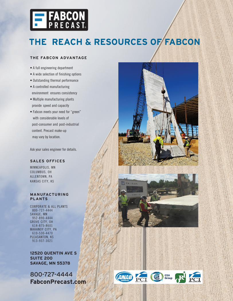
THE REACH & RESOURCES OF FABCON
THE FABCON ADVANTAGE
• A full engineering department
• A wide selection of finishing options
• Outstanding thermal performance
• A controlled manufacturing
environment ensures consistency
• Multiple manufacturing plants
provide speed and capacity
• Fabcon meets your need for “green”
with considerable levels of
post-consumer and post-industrial
content. Precast make-up
may vary by location.
Ask your sales engineer for details.
SALES OFFICES
MINNEAPOLIS, MNCOLUMBUS, OH ALLENTOWN, PAKANSAS CITY, KS
MANUFACTURINGPLANTS
CORPORATE & ALL PLANTS 800-727-4444SAVAGE, MN 952-890-4444GROVE CITY, OH 614-875-8601MAHANOY CITY, PA 610-530-4470PLEASANTON, KS 913-937-3021
12520 QUENTIN AVE S SUITE 200 SAVAGE, MN 55378
800-727-4444 FabconPrecast.com
Related Documents