Manufacturing Processes Chapters Ten & Eleven: Fundamentals of Metal Casting & Metals For Casting Dr. Eng. Yazan Al-Zain Department of Industrial Engineering

Manufacturing Ch10 and 11 - Casting - GearTeam
Dec 24, 2015
metal casting principles
Welcome message from author
This document is posted to help you gain knowledge. Please leave a comment to let me know what you think about it! Share it to your friends and learn new things together.
Transcript
Manufacturing Processes
Chapters Ten & Eleven:
Fundamentals of Metal Casting & MetalsFor Casting
Dr. Eng. Yazan Al-ZainDepartment of Industrial Engineering
Introduction
• In casting, the starting work material is either a liquid or is in a highlyplastic condition, and a part is created through solidification of thematerial.
• Casting and molding processes dominate this category of shapingprocesses.
• The solidification processes can be classified according toengineering material processed: :
– Metals.
– Ceramics, specifically glasses.
– Polymers and polymer matrix composites (PMCs).
Introduction
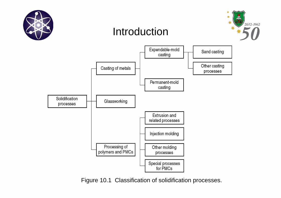
Figure 10.1 Classification of solidification processes.
Introduction
• Casting is the process in which molten metal flows by gravity or otherforce into a mold where it solidifies in the shape of the mold cavity.
• The term casting is also applied to the part that is made by thisprocess.
• Principle of casting is pretty simple:
– Melt the metal.
– Pour it into a mold.
– Let it freeze.
• However, to accomplish a successful casting, many variables and factorsmust be considered.
Introduction
• Casting include both the casting of ingots andthe casting of shapes.
– Ingot casting: it describes a large casting that issimple in shape and intended for subsequentreshaping by processes such as rolling or forging.
– Shape casting: involves the production of morecomplex geometries that are much closer to the finaldesired shape.
Introduction
• Casting capabilities and advantages can be summarized as follows:
– Casting can create complex part geometries, including bothexternal and internal shapes.
– Some casting processes are capable of producing net shape;others are capable of producing near net shape (need furtherprocessing).
– Casting can be used to produce very large parts.
– Can be performed on any metal that can be heated to the liquidstate.
– Some casting processes are suited to mass production.
Introduction
• Casting processes have also disadvantages; differentdisadvantages for different casting methods:
– Limitations on mechanical properties.
– Porosity.
– Poor dimensional accuracy and surface finish for some processes.
– Safety hazards to humans when processing hot molten metals.
– Environmental problems.
Overview of Casting Technology
• Casting is usually performed in a foundry by foundrymen.
- A foundry: a factory equipped for making molds,melting and handling molten metal, performing thecasting process, and cleaning the finished casting.
- Foundrymen: are those workers who perform casting.
Overview of Casting Technology;Casting Processes
• Discussion of casting begins with molds.
– A mold contains a cavity whose geometry determines the shapeof the cast part.
– The actual size and shape of cavity must be slightly oversized toallow for shrinkage that occurs in the metal during solidificationand cooling.
– Amount of shrinkage depends on metal type, so design must bemade for the particular metal being cast.
– Molds are made of a variety of materials, including sand, plaster,ceramic, and metal.
Overview of Casting Technology;Casting Processes
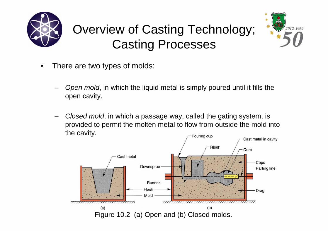
• There are two types of molds:
– Open mold, in which the liquid metal is simply poured until it fills theopen cavity.
– Closed mold, in which a passage way, called the gating system, isprovided to permit the molten metal to flow from outside the mold intothe cavity.
Figure 10.2 (a) Open and (b) Closed molds.
Overview of Casting Technology;Casting Processes
• There are two broad categories of casting:
– Expandable mold casting processes, in which an expendable mold isused and must be destroyed to remove casting. These molds are madeout of sand, plaster, whose form is maintained by using binders. Abilityto produce complex geometries is an advantage of the expandablemold casting.
– Permanent mold casting processes, in which a permanent mold can beused over and over again. It is made of metal (or, less commonly, aceramic refractory material). The mold is composed of two sections thatcan be separated from each other to remove the casting. Example isdie casting. Some permanent mold casting processes have certaineconomic advantages.
Overview of Casting Technology;Sand Casting Molds
• Sand casting is by far the most important casting process.
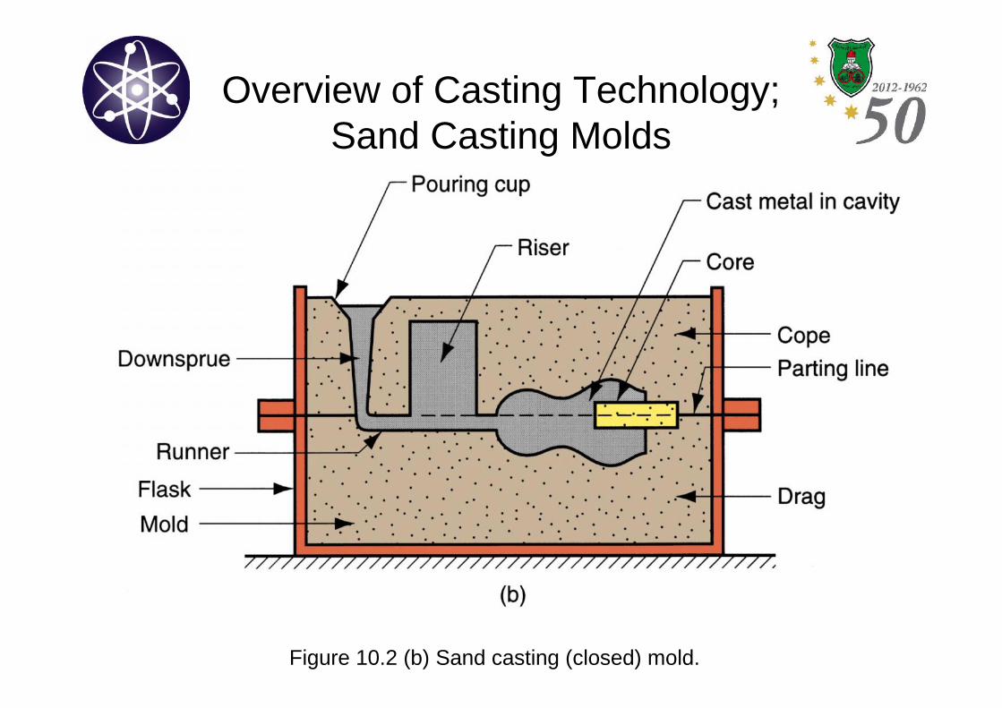
– Mold consists of 2 halves; cope and drag.
• Cope is the upper half of the mold.• Drag is the bottom half of the mold.
– Cope and drag are contained in a box called flask. The flask is alsodivided into 2 halves; one for the cope and the other for the drag.
– Parting line: separates the two halves of the mold.
Overview of Casting Technology;Sand Casting Molds
Figure 10.2 (b) Sand casting (closed) mold.
Overview of Casting Technology;Sand Casting Molds
• In sand casting and other expandable mold processes:
– Pattern: the mold cavity is formed by means of a pattern.
• It is made of wood, metal, plastic, etc, and has the shape of thepart to be cast.
• The cavity is formed by packing sand around the pattern.
• Usually made oversized to allow for shrinkage as the metalsolidifies.
• The cavity in the mold provides the external surfaces of the castpart.
• The core; the internal surfaces are determined by means of a core,which is a form placed inside the mold cavity to define the interiorgeometry of the part. “Generally made from sand in sand casting”.
Overview of Casting Technology;Sand Casting Molds
• In sand casting and other expandable mold processes:
– Gating system: is a channel or network of channels, bywhich molten metal flows into the cavity from outside themold.
• The gating system consists of a downsprue (or simply sprue),through which a metal enters a runner that leads into themain cavity.
• Pouring cup, found at the top of the downsprue. It is oftenused to minimize splash and turbulence as the metal flowsinto the downsprue.
Overview of Casting Technology;Sand Casting Molds
• In sand casting and other expandable mold processes:
– Riser: is a reservoir in the mold that serves as a source ofliquid metal for the casting to compensate for shrinkageduring solidification .
• It is designed to freeze after the main casting in order tosatisfy its function
Overview of Casting Technology;Sand Casting Molds
• The air that previously occupied the cavity, as well ashot gases formed by the reactions of the molten metal,must be evacuated so that the metal will completely fillthe empty space.
– In sand casting, the natural porosity of the sand mold permitsthe air and gases to escape through the walls of the cavity.
– In permanent metal molds, small vent holes are drilled into themold or machined into the parting line to permit removal of airand gases.
Heating and PouringHeating the Metal
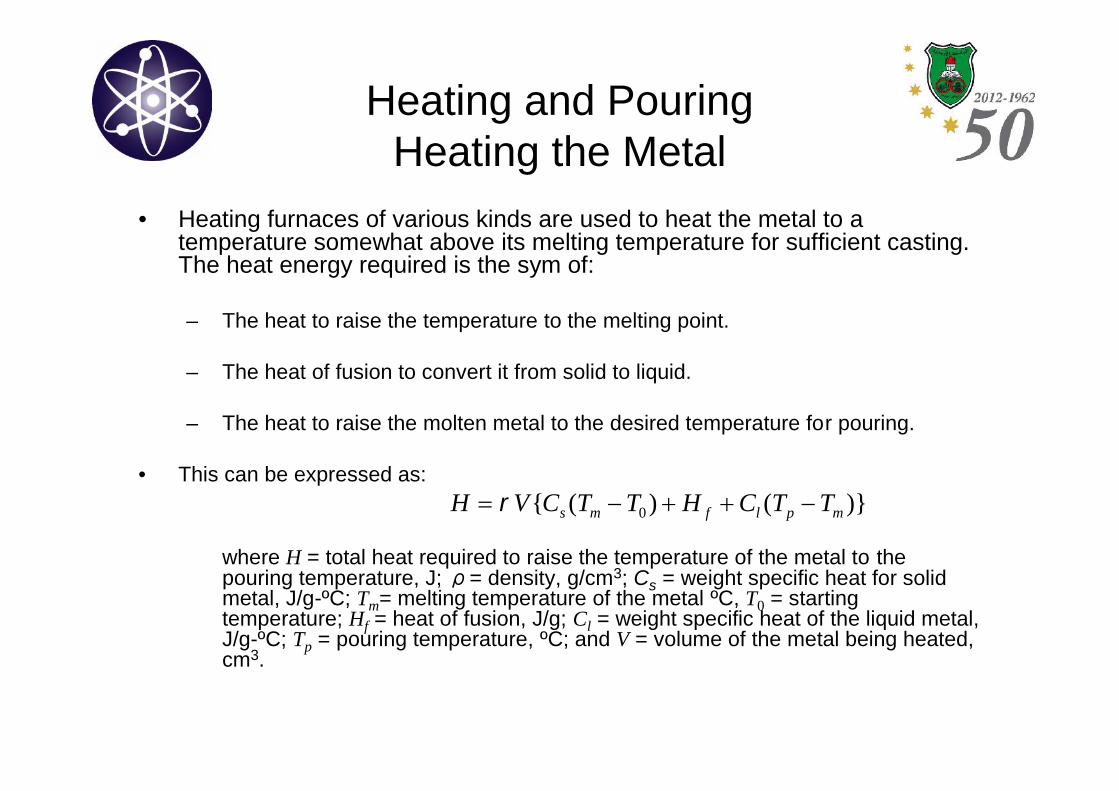
• Heating furnaces of various kinds are used to heat the metal to atemperature somewhat above its melting temperature for sufficient casting.The heat energy required is the sym of:
– The heat to raise the temperature to the melting point.
– The heat of fusion to convert it from solid to liquid.
– The heat to raise the molten metal to the desired temperature for pouring.
• This can be expressed as:
where H = total heat required to raise the temperature of the metal to thepouring temperature, J; ρ= density, g/cm3; Cs = weight specific heat for solidmetal, J/g-ºC; Tm= melting temperature of the metal ºC, T0 = startingtemperature; Hf = heat of fusion, J/g; Cl = weight specific heat of the liquid metal,J/g-ºC; Tp = pouring temperature, ºC; and V = volume of the metal being heated,cm3.
)}()({ 0 mplfms TTCHTTCVH
Heating and PouringPouring the Molten Metal
• For this step to be successful, metal must flow into allregions of the mold, most importantly the main cavity,before solidifying. Factors affecting the pouringoperation include:
– The pouring temperature: temperature of the metal introducedinto the mold. Here, superheat is important; the differencebetween the temperature at pouring and the temperature atwhich freezing begins.
– The pouring rate: volumetric rate at which the molten metal ispoured into the mold. Too slow rates will cause freezing beforemetal fills the cavity and excessive rates will cause turbulence.
– Turbulence: sudden variations in the magnitude and velocitythroughout the liquid. It tends to accelerate the formation ofmetal oxides. It also aggravates mold erosion due to impact ofthe flowing molten metal.
Heating and PouringEngineering Analyses of Pouring
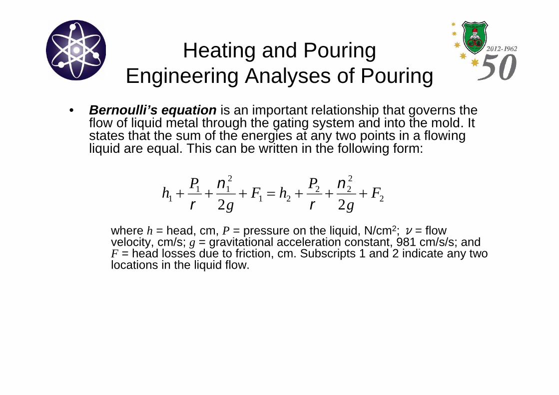
• Bernoulli’s equation is an important relationship that governs theflow of liquid metal through the gating system and into the mold. Itstates that the sum of the energies at any two points in a flowingliquid are equal. This can be written in the following form:
where h = head, cm, P = pressure on the liquid, N/cm2;ν= flowvelocity, cm/s; g = gravitational acceleration constant, 981 cm/s/s; andF = head losses due to friction, cm. Subscripts 1 and 2 indicate any twolocations in the liquid flow.
2
222
21
211
1 22F
g
PhF
g
Ph
Heating and PouringEngineering Analyses of Pouring
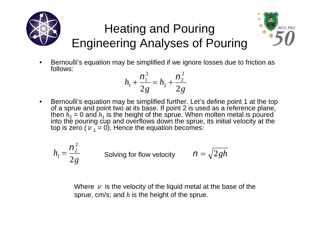
• Bernoulli’s equation may be simplified if we ignore losses due to friction asfollows:
• Bernoulli’s equation may be simplified further. Let’s define point 1 at the topof a sprue and point two at its base. If point 2 is used as a reference plane,then h2 = 0 and h1 is the height of the sprue. When molten metal is pouredinto the pouring cup and overflows down the sprue, its initial velocity at thetop is zero (ν1 = 0). Hence the equation becomes:
gh
gh
22
22
2
21
1
gh
2
22
1
gh2Solving for flow velocity
Whereν is the velocity of the liquid metal at the base of thesprue, cm/s; and h is the height of the sprue.
Heating and PouringEngineering Analyses of Pouring
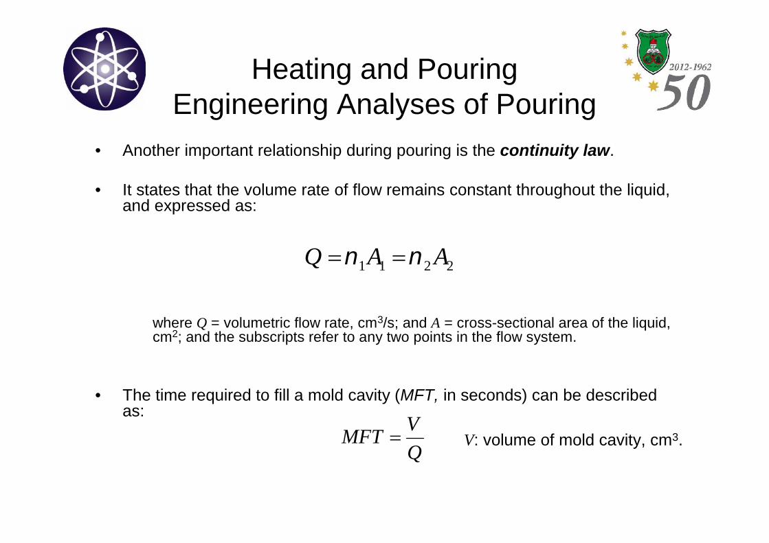
• Another important relationship during pouring is the continuity law.
• It states that the volume rate of flow remains constant throughout the liquid,and expressed as:
where Q = volumetric flow rate, cm3/s; and A = cross-sectional area of the liquid,cm2; and the subscripts refer to any two points in the flow system.
• The time required to fill a mold cavity (MFT, in seconds) can be describedas:
2211 AAQ
Q
VMFT V: volume of mold cavity, cm3.
Heating and PouringFluidity
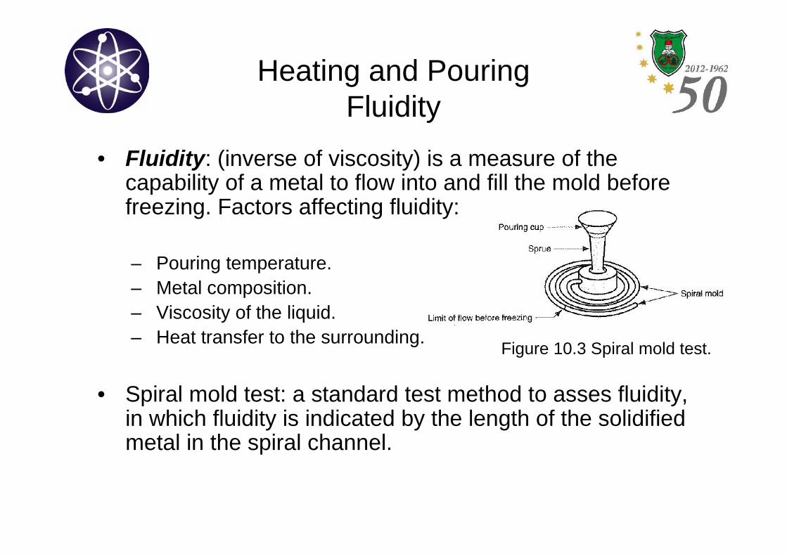
• Fluidity: (inverse of viscosity) is a measure of thecapability of a metal to flow into and fill the mold beforefreezing. Factors affecting fluidity:
– Pouring temperature.– Metal composition.– Viscosity of the liquid.– Heat transfer to the surrounding.
• Spiral mold test: a standard test method to asses fluidity,in which fluidity is indicated by the length of the solidifiedmetal in the spiral channel.
Figure 10.3 Spiral mold test.
Solidification and CoolingSolidification of Metals
• Solidification: the transformation of the molten metalback into the solid state. (differs depending oncomposition and purity). Pure metals freeze at aconstant temperature while alloys, except for theeutectic compositions, freeze over a temperature range.
• Fluidity of pure metals are better than that of alloys.When solidification occurs over a temperature range, thepartially solidified portion interferes with the flow of theliquid portion, hence reducing fluidity.
Solidification and CoolingSolidification of Metals
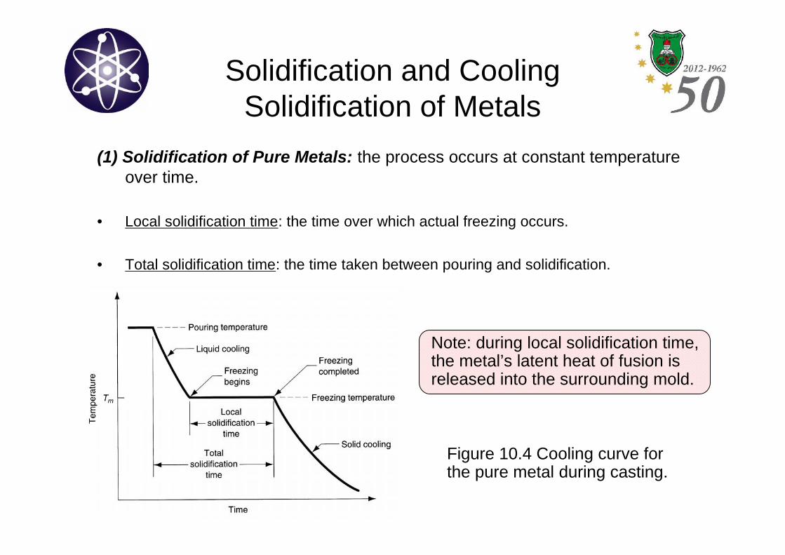
(1) Solidification of Pure Metals: the process occurs at constant temperatureover time.
• Local solidification time: the time over which actual freezing occurs.
• Total solidification time: the time taken between pouring and solidification.
Figure 10.4 Cooling curve forthe pure metal during casting.
Note: during local solidification time,the metal’s latent heat of fusion isreleased into the surrounding mold.
Solidification and CoolingSolidification of Metals
• Because of the chilling action of the mold wall, a thinskin of solid metal is initially formed at the interfaceimmediately after pouring.
• Skin thickness increases to form a shell around themolten metal as solidification progresses inward towardthe center of the cavity.
• Rate of freezing depends on heat transfer into mold, aswell as the thermal properties of the metal.
Solidification and CoolingSolidification of Metals
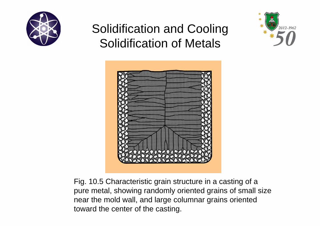
• The metal which forms the initial skin has been rapidlycooled by the extraction of heat through the mold wall.This causes the grains in the skin to be fine, equiaxed,and randomly oriented.
• Further grain formation and growth occurs in a directionaway from the heat transfer. The grains grow inwardlyas needles of solid metal since the heat transfer isthrough skin and mold wall (slower cooling rate). Thistype of grain growth is referred to as dendritic growth.See Fig. 10.5.
Solidification and CoolingSolidification of Metals
Fig. 10.5 Characteristic grain structure in a casting of apure metal, showing randomly oriented grains of small sizenear the mold wall, and large columnar grains orientedtoward the center of the casting.
Solidification and CoolingSolidification of Metals
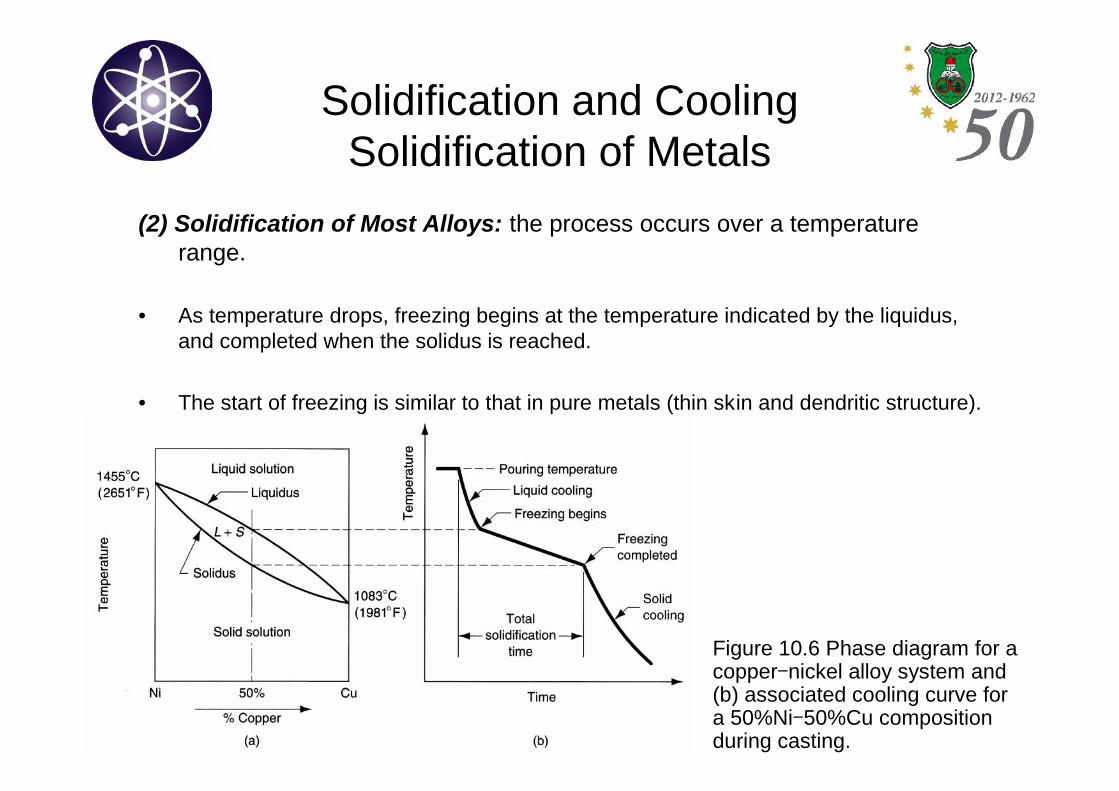
(2) Solidification of Most Alloys: the process occurs over a temperaturerange.
• As temperature drops, freezing begins at the temperature indicated by the liquidus,and completed when the solidus is reached.
• The start of freezing is similar to that in pure metals (thin skin and dendritic structure).
Figure 10.6 Phase diagram for acopper-nickel alloy system and(b) associated cooling curve fora 50%Ni-50%Cu compositionduring casting.
Solidification and CoolingSolidification of Metals
• Mushy zone: a solid-liquid region that has a soft consistency.
• The slower the heat transfer and the wider the difference between liquidusand solidus, the broader the mushy zone.
• The liquid islands in the dendritic matrix solidify gradually as thetemperature of the casting drops.
• The dendritic structure favors the metal with the highest melting point. Inother words, there would become a composition imbalance between themetal that has solidified and the remaining molten metal (variations inchemical composition throughout the casting).
• This leads to segregation of elements in the casting (called ingotsegregation).
Solidification and CoolingSolidification of Metals
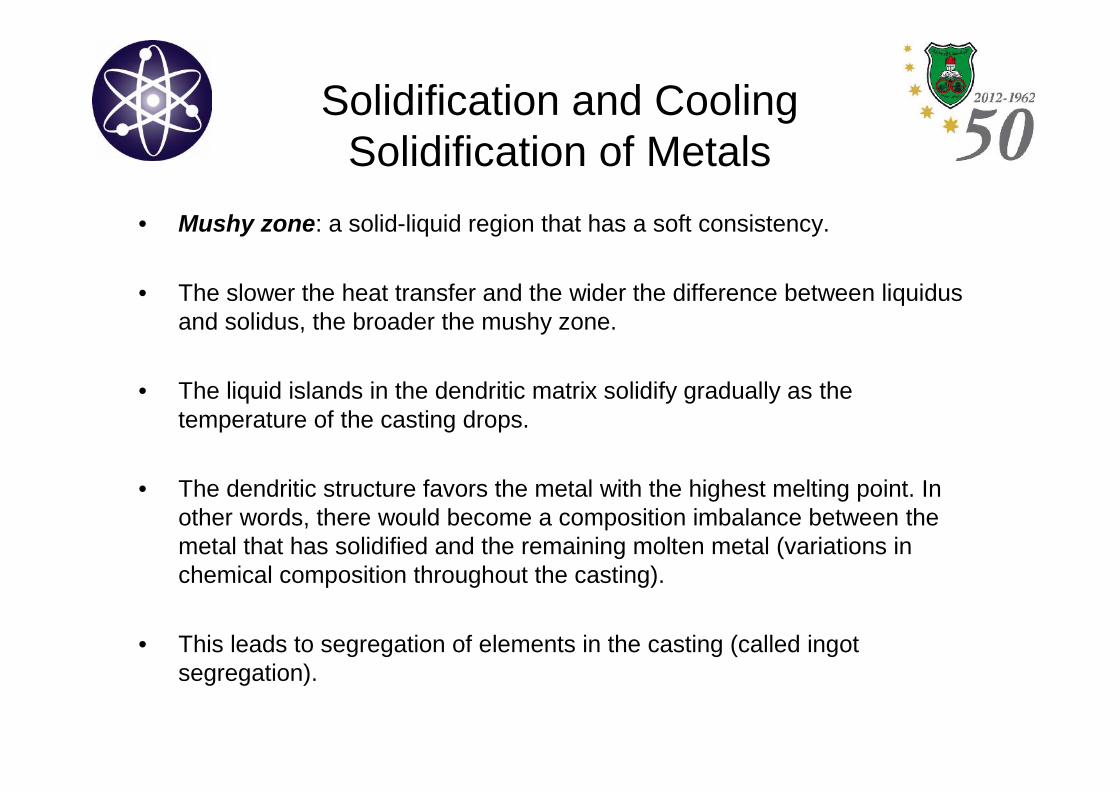
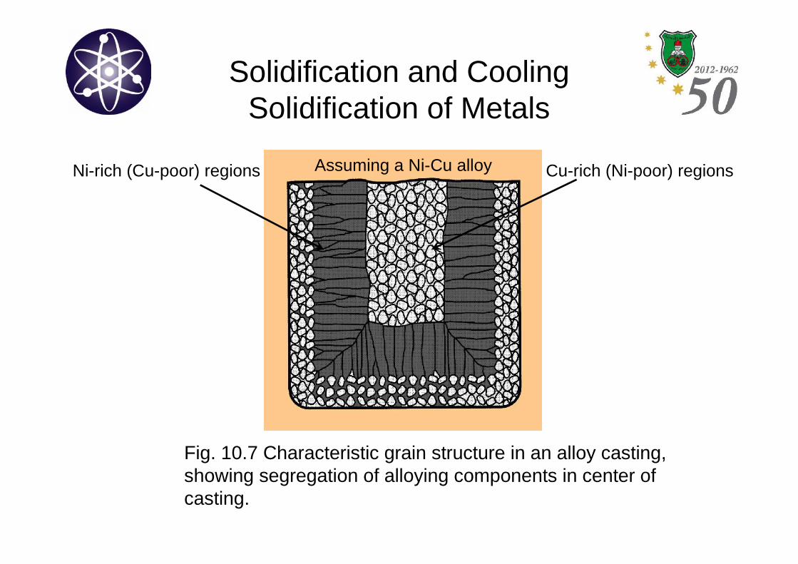
Fig. 10.7 Characteristic grain structure in an alloy casting,showing segregation of alloying components in center ofcasting.
Assuming a Ni-Cu alloyNi-rich (Cu-poor) regions Cu-rich (Ni-poor) regions
Solidification and CoolingSolidification of Metals
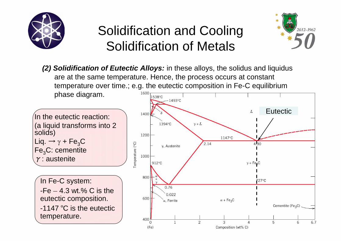
(2) Solidification of Eutectic Alloys: in these alloys, the solidus and liquidusare at the same temperature. Hence, the process occurs at constanttemperature over time.; e.g. the eutectic composition in Fe-C equilibriumphase diagram.
Eutectic
In Fe-C system:-Fe – 4.3 wt.% C is theeutectic composition.-1147 ºC is the eutectictemperature.
In the eutectic reaction:(a liquid transforms into 2solids)Liq.→ + Fe3CFe3C: cementiteγ: austenite
Solidification and CoolingSolidification Time
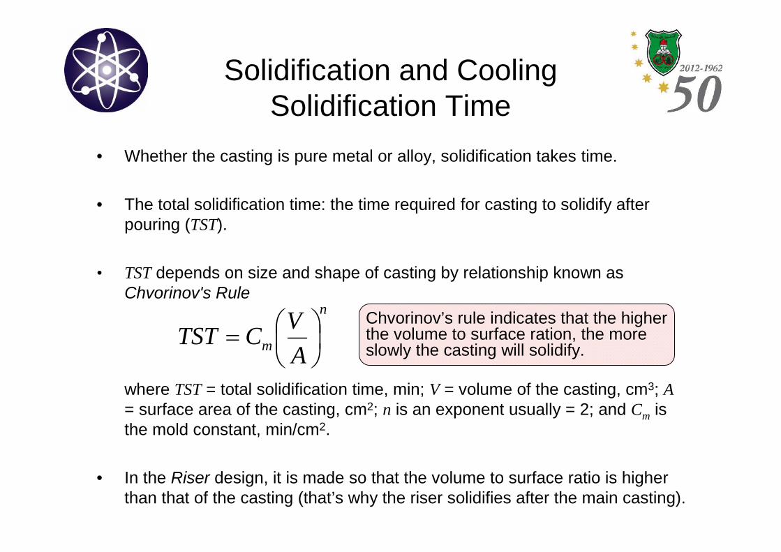
• Whether the casting is pure metal or alloy, solidification takes time.
• The total solidification time: the time required for casting to solidify afterpouring (TST).
• TST depends on size and shape of casting by relationship known asChvorinov's Rule
where TST = total solidification time, min; V = volume of the casting, cm3; A= surface area of the casting, cm2; n is an exponent usually = 2; and Cm isthe mold constant, min/cm2.
• In the Riser design, it is made so that the volume to surface ratio is higherthan that of the casting (that’s why the riser solidifies after the main casting).
n
m A
VCTST
Chvorinov’s rule indicates that the higherthe volume to surface ration, the moreslowly the casting will solidify.
Solidification and CoolingShrinkage
• During cooling, shrinkage occurs in three steps:
– Liquid contraction during cooling prior to solidification.
– Contraction during the phase change from liquid to solid, calledsolidification shrinkage.
– Thermal contraction of the solidified casting during cooling toroom temperature.
Solidification and CoolingShrinkage
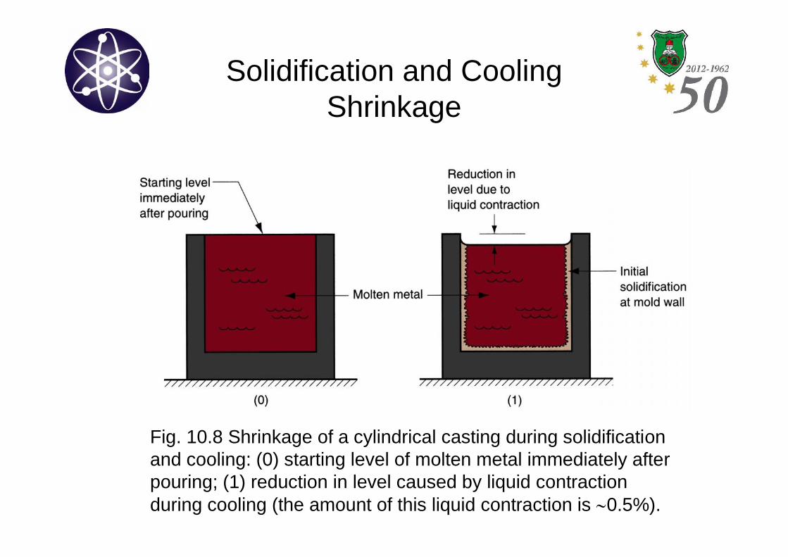
Fig. 10.8 Shrinkage of a cylindrical casting during solidificationand cooling: (0) starting level of molten metal immediately afterpouring; (1) reduction in level caused by liquid contractionduring cooling (the amount of this liquid contraction is 0.5%).
Solidification and CoolingShrinkage
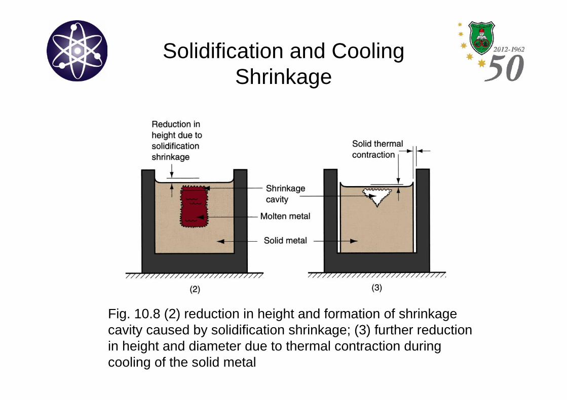
Fig. 10.8 (2) reduction in height and formation of shrinkagecavity caused by solidification shrinkage; (3) further reductionin height and diameter due to thermal contraction duringcooling of the solid metal
Solidification and CoolingShrinkage
• Solidification shrinkage occurs in nearly all metalsbecause the solid phase has a higher density than theliquid phase.
• The phase transformation that accompaniessolidification causes a reduction in volume per unitweight of metal.
• Cast iron with high carbon content is an exception asgraphitization during final stages of freezing causesexpansion that tends to counteract the volumetricdecrease associated with the phase change.
Solidification and CoolingShrinkage
• Patternmakers account for solidificationshrinkage and thermal contraction by makingthe mold cavities oversized.
• The amount by which the mold must be madelarger relative to final casting size is calledpattern shrinkage allowance.
Solidification and CoolingDirectional Solidification
• In order to minimize the damaging effects of shrinkage, it isdesirable for the regions of the casting most distant from the liquidmetal supply to freeze first and for solidification to progress fromthese remote regions toward the riser(s).
• In this way, the molten metal will continually be available from therisers to prevent shrinkage voids during freezing.
• The term directional solidification is used to describe this aspectof the freezing process and the methods by which it is controlled.
Solidification and CoolingDirectional Solidification
• The directional solidification is achieved by observing Chvorinov'sRule in the design of the casting itself, its orientation within the mold,and the design of the riser system that feeds it.
• For example, by locating sections of the casting with lower V / Aratios away from the riser, freezing will occur first in these regionsand the supply of liquid metal for the rest of the casting will remainopen until the bulkier sections solidify.
Solidification and CoolingDirectional Solidification
• The directional solidification may also be achieved by the use ofchills; internal or external heat sinks that cause rapid freezing incertain regions of the casting.
– Internal chills: small metal parts placed inside the cavity before pouringso that molten metal will solidify first around these parts.
– External chills: metal inserts in the walls of the mold cavity that canremove heat from the molten metal more rapidly than the surroundingsand in order to promote solidification.
Solidification and CoolingDirectional Solidification
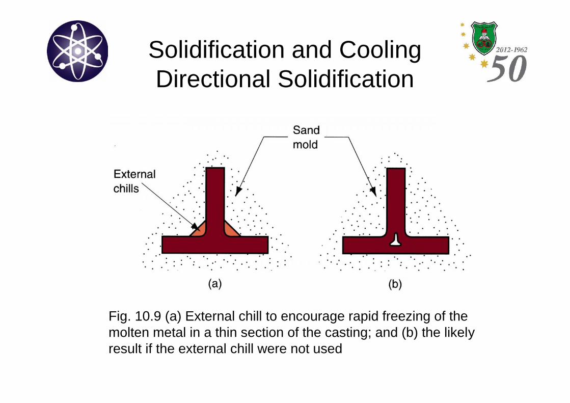
Fig. 10.9 (a) External chill to encourage rapid freezing of themolten metal in a thin section of the casting; and (b) the likelyresult if the external chill were not used
Solidification and CoolingRiser Design
• Riser is used in sand casting to feed liquid metal to the castingduring freezing to compensate for solidification shrinkage.
• The riser must remain molten until after the casting solidifies.
• Chvorinov’s Rule is used to compute the size of the riser thatsatisfies this requirement.
• As the riser is not a part of the casting, it will be separated from thecast part after casting is finished. Hence, it is desirable for thevolume of metal in the riser to be minimum.
Solidification and CoolingRiser Design
• Risers can be designed in various forms:
– Side riser: attached to the side of the casting by means of a smallchannel.
– Top riser: connected to the top surface of the casting.
• Risers can be open or blind:
– Open riser: exposed to the outside at the top surface of the cope(disadvantageous as heat will escape faster).
– Blind riser: entirely closed within the mold.
Solidification and CoolingRiser Design
• Example 10.3: Riser design using Chvorinov’s Rule.
End of Chapter 10
Sand Casting
• Sand casting is by far most widely used casting process.
• Nearly all alloys can be sand casted.
• Sand casting is one of the few processes that can beused for metals with high melting points, such as steeland nickel.
• Parts from small to large sizes and quantities from oneto millions can be sand-casted.
Sand Casting
• Sand casting consists of:
– Pouring molten metal into sand mold.
– Allowing the metal to solidify.
– Breaking up the mold to remove the casting.
– Cleaning and inspecting the casting.
– Heat treatment is sometimes required to improve metallurgicalproperties
Sand Casting
• The cavity in the sand mold is formed by packing sandaround a pattern, and then separating the mold into twohalves to remove the pattern.
• The mold also contains the gating and riser system.
• If casting is to have internal surfaces, a core must beincluded in the mold.
• A new sand mold must be made for each partproduced, since the mold is sacrificed to remove thecasting.
Sand CastingPatterns and Cores
• The pattern is a full-sized model of the part, enlarged to accountfor shrinkage and machining allowances.
• Made of plastic, wood or metals.
• Wood is cheap and easy to machine.
• Wood however, tend to wrap. Thus, limiting the number of times itcan be used.
• Metal is more expensive, but it can be a good choice if the numberof parts to be made is high.
• Plastic represent a compromise between wood and metal.
Sand CastingPatterns and Cores
• There are various types of patterns:
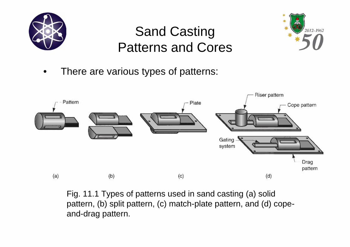
– Solid pattern: simplest type and easiest to fabricate. However,it is not the easiest to use in making a sand mold (difficult todetermine the parting line, also incorporating the raiser andgating system needs high skill).
– Split patterns: consist of 2 pieces, dividing the part along aline coinciding with the mold’s parting line. These patterns areappropriate for complex part geometries and moderatequantities.
Sand CastingPatterns and Cores
• There are various types of patterns:
– Match-plate patterns: appropriate for high productionquantities. In these patterns, the two pieces of the split patternare attached to opposite sides of a wood or metal plate. Holesin the plate allow the cope and drag of the mold to be alignedaccurately.
– Cope-and-drag patterns: appropriate for high productionquantities. Similar to match-plate patterns except that splitpattern halves are attached to separate plates so that the cope-and-drag sections can be fabricated independently, instead ofusing the same tooling for both.
Sand CastingPatterns and Cores
• There are various types of patterns:
Fig. 11.1 Types of patterns used in sand casting (a) solidpattern, (b) split pattern, (c) match-plate pattern, and (d) cope-and-drag pattern.
Sand CastingPatterns and Cores
• The core defines the internal features of a casting.
• Usually made of sand, compacted into the desiredshape.
• As with the pattern, the actual size of the core mustaccount for the shrinkage and machining.
• Chaplets: supports for the core. The may or may notbe necessary depending on the part’s geometry. Theyare made of metals that have higher melting pointsthan the casting.
Sand CastingPatterns and Cores
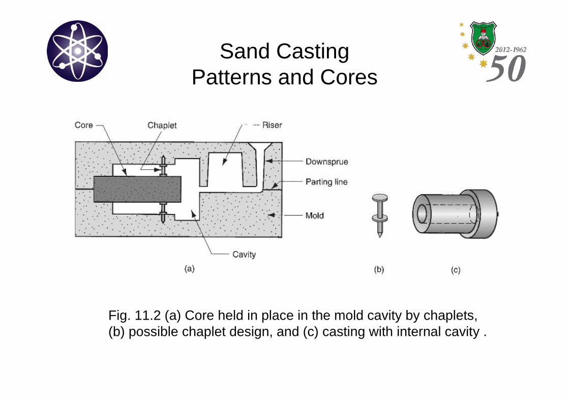
Fig. 11.2 (a) Core held in place in the mold cavity by chaplets,(b) possible chaplet design, and (c) casting with internal cavity .
Sand CastingMolds and mold making
• Foundry sands are silica, or silica mixed with other minerals.
• Sand should be able to stand high temperatures without melting ordegrading.
• Sand should have appropriate size to provide a good surfacefinish on the cast part and allow for gases to escape duringpouring.
• Small sizes provide a good surface finish but have lowerpermeability compared to large sizes.
• Sand particles are held together by water and clay (by volume:90%, 3% and 7%, respectively).
Sand CastingMolds and mold making
• The mold cavity is formed by compacting thesand around the pattern for both cope and dragcontained in the flask.
• The simplest packing process is handhammering, accomplished manually by afoundry worker.
• In addition, various machines have beendeveloped to mechanize the packing procedure.
Sand CastingMolds and mold making
• The quality of the sand mold is determined by:
– Strength: the mold’s ability to maintain its shape and resist erosioncaused by the flow of molten metal. It depends on grain size andshape and binders quality.
– Permeability: ability of the mold to allow gases to pass through thesand voids.
– Thermal stability: ability of the sand at the surface of the mold cavity toresist cracking and buckling upon contact with the molten metal.
– Collapsibility: ability of the sand to give way and allow the casting toshrink without cracking the casting. It also refers to the ability toremove the sand from the casting during cleaning.
– Reusability: ability to reuse the sand to make other molds.
Sand CastingMolds and mold making
• Sand molds classifications:
– Green-sand molds: made of sand, clay and water. Theycontain moisture at the time of pouring. They possess goodstrength, good collapsibility and permeability, good reusabilityand the least expensive of the molds. Moisture however, cancause some defects in the castings.
– Dry-sand molds: made of organic binders. The mold is backedin an oven at temperatures between 200 and 320 ºC forstrengthening and hardening reasons. Better dimensionalaccuracy compared to green-sand molds but more expensive.
– Skin-dried mold: the advantages of dry-sand molds are partiallyachieved by drying the surface of a green-sand mold to a depthof 10 to 25 mm.
Sand CastingThe Casting Operation
• After the core is positioned and the two halves of the mold are clampedtogether, the casting is performed.
• The gating and the riser system in the system must be designed to deliverliquid metal into the cavity, and provide for a sufficient reservoir of moltenmetal during solidification shrinkage.
• Air and gasses must be allowed to escape.
• Following solidification and cooling, the sand mold is broken away fromthe casting to retrieve the part.
• The part is then cleaned, gating and riser system is separated and sand isremoved.
• Finally, casting is inspected.
Sand CastingThe Casting Operation
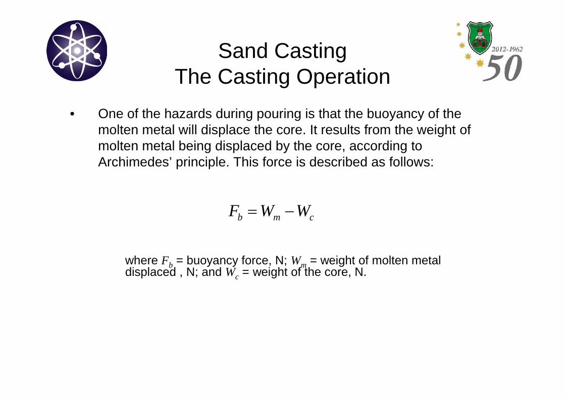
• One of the hazards during pouring is that the buoyancy of themolten metal will displace the core. It results from the weight ofmolten metal being displaced by the core, according toArchimedes’ principle. This force is described as follows:
cmb WWF
where Fb = buoyancy force, N; Wm = weight of molten metaldisplaced , N; and Wc = weight of the core, N.
Other Expandable-Mold-CastingProcesses
• Other casting processes that have beendeveloped to meet special needs.
• The difference between these methods are in:
– The composition of the mold material.
– Or the manner in which the mold is made.
– Or in the way the pattern is made.
Other Expandable-Mold-CastingProcesses
Shell Molding• Shell molding: is a casting process in which the mold is a thin
shell made of sand held together by thermosetting resin binder.
• Was developed in Germany in the early 1940s.
• Steps of shell molding: (See next figures).
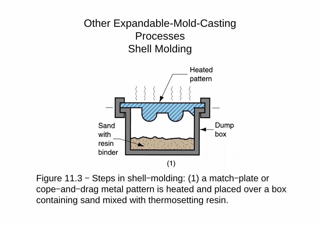
Figure 11.3 - Steps in shell-molding: (1) a match-plate orcope-and-drag metal pattern is heated and placed over a boxcontaining sand mixed with thermosetting resin.
Other Expandable-Mold-CastingProcesses
Shell Molding
Other Expandable-Mold-CastingProcesses
Shell Molding
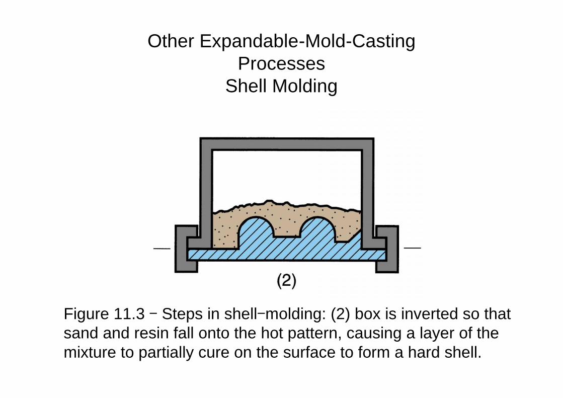
Figure 11.3 - Steps in shell-molding: (2) box is inverted so thatsand and resin fall onto the hot pattern, causing a layer of themixture to partially cure on the surface to form a hard shell.
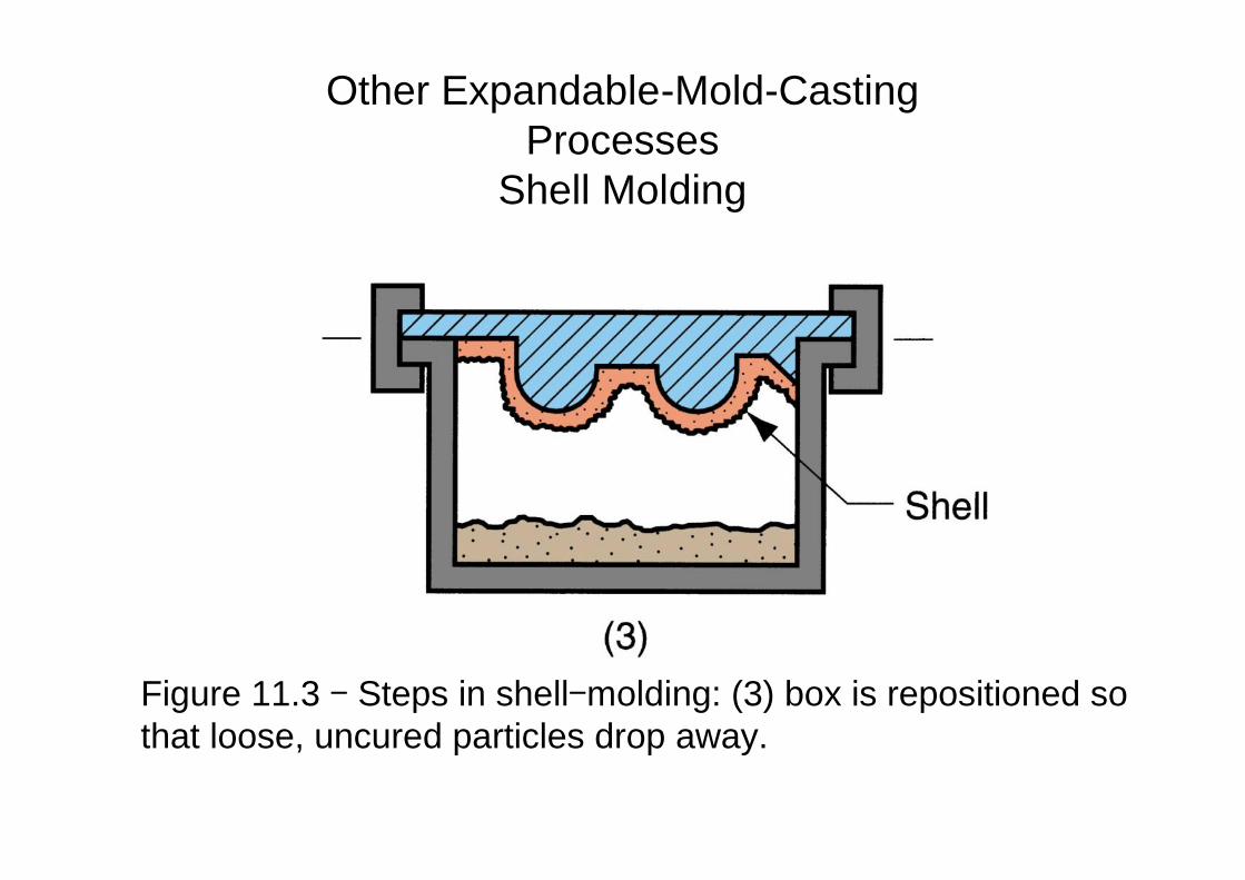
Figure 11.3 - Steps in shell-molding: (3) box is repositioned sothat loose, uncured particles drop away.
Other Expandable-Mold-CastingProcesses
Shell Molding
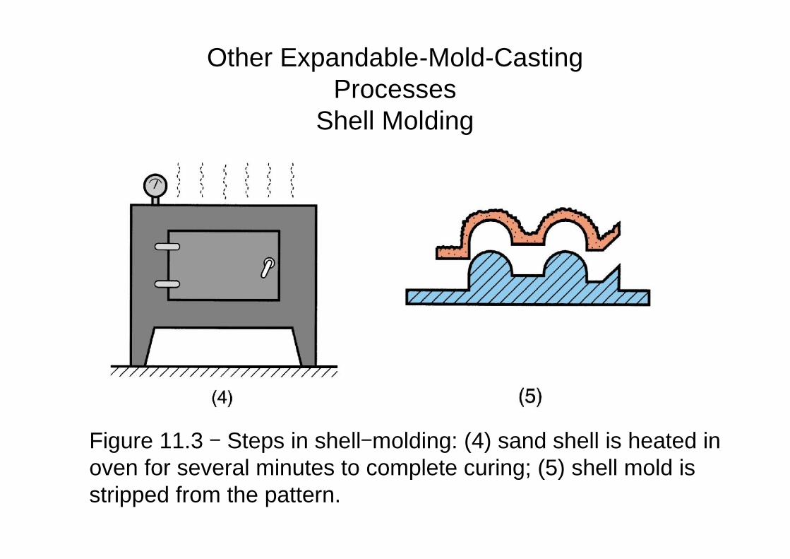
Figure 11.3 - Steps in shell-molding: (4) sand shell is heated inoven for several minutes to complete curing; (5) shell mold isstripped from the pattern.
Other Expandable-Mold-CastingProcesses
Shell Molding
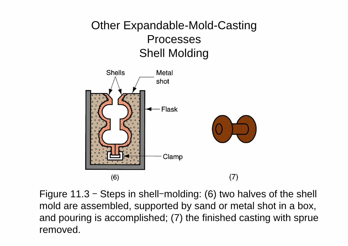
Figure 11.3 - Steps in shell-molding: (6) two halves of the shellmold are assembled, supported by sand or metal shot in a box,and pouring is accomplished; (7) the finished casting with sprueremoved.
Other Expandable-Mold-CastingProcesses
Shell Molding
Other Expandable-Mold-CastingProcesses
Shell Molding• There are many advantages of shell molding:
– The surface of the shell mold cavity is smoother than in a conventionalgreen-sand mold.
– This smoothness permits easier flow of molten metal during pouringand better surface finish on casting.
– Good dimensional accuracy (due to good finish and accuracy, theneed for machining is minimized).
– Sufficient mold collapsibility to avoid tearing and cracking of casting.
– Can be mechanized for mass production.
– Very economical for large quantities.
Other Expandable-Mold-CastingProcesses
Shell Molding• There are also some disadvantages of shell molding:
– More expensive metal pattern than the correspondingpattern for green-sand molding. This makes the shellmolding difficult to justify for small quantities.
• Examples of parts made using shell molding:
– Gears.
– Camshafts.
Other Expandable-Mold-CastingProcesses
Vacuum Molding• Vacuum molding: it uses a sand mold held together by vacuum
pressure rather than a chemical binder.
• Was developed in Japan around 1970.
• Steps of vacuum molding: (See next figures).
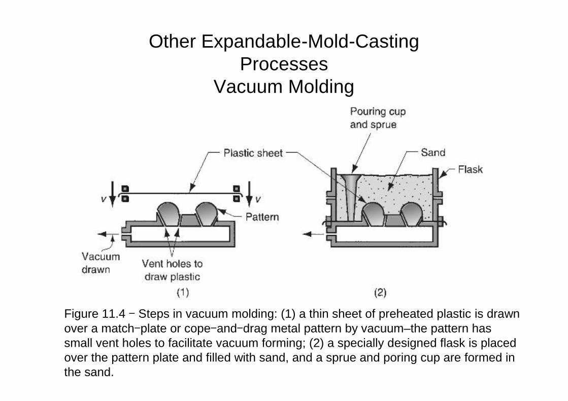
Figure 11.4 - Steps in vacuum molding: (1) a thin sheet of preheated plastic is drawnover a match-plate or cope-and-drag metal pattern by vacuum–the pattern hassmall vent holes to facilitate vacuum forming; (2) a specially designed flask is placedover the pattern plate and filled with sand, and a sprue and poring cup are formed inthe sand.
Other Expandable-Mold-CastingProcesses
Vacuum Molding
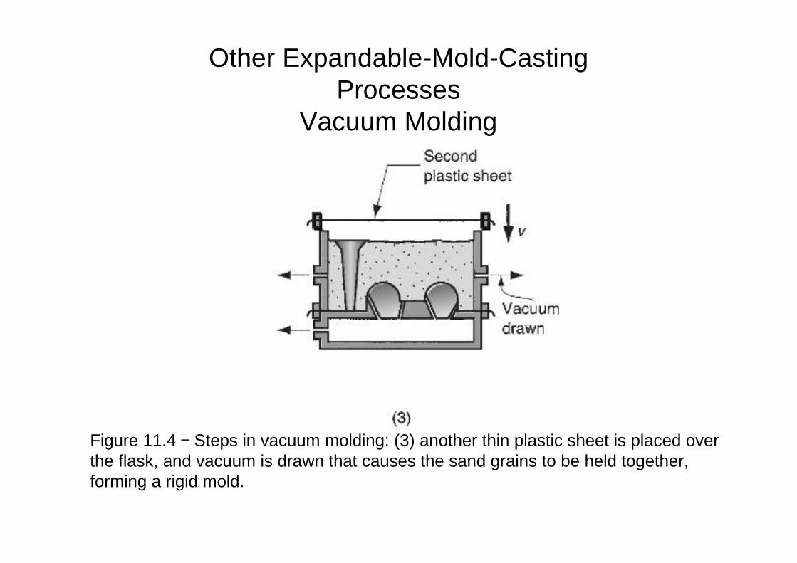
Figure 11.4 - Steps in vacuum molding: (3) another thin plastic sheet is placed overthe flask, and vacuum is drawn that causes the sand grains to be held together,forming a rigid mold.
Other Expandable-Mold-CastingProcesses
Vacuum Molding
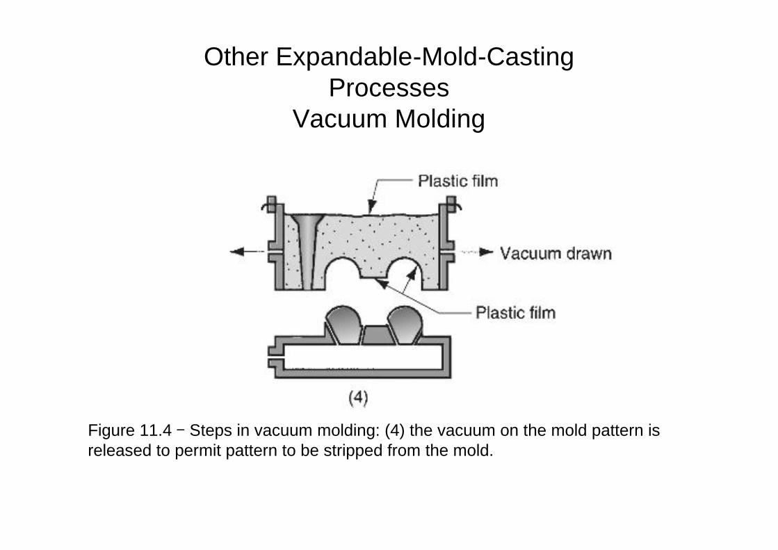
Figure 11.4 - Steps in vacuum molding: (4) the vacuum on the mold pattern isreleased to permit pattern to be stripped from the mold.
Other Expandable-Mold-CastingProcesses
Vacuum Molding
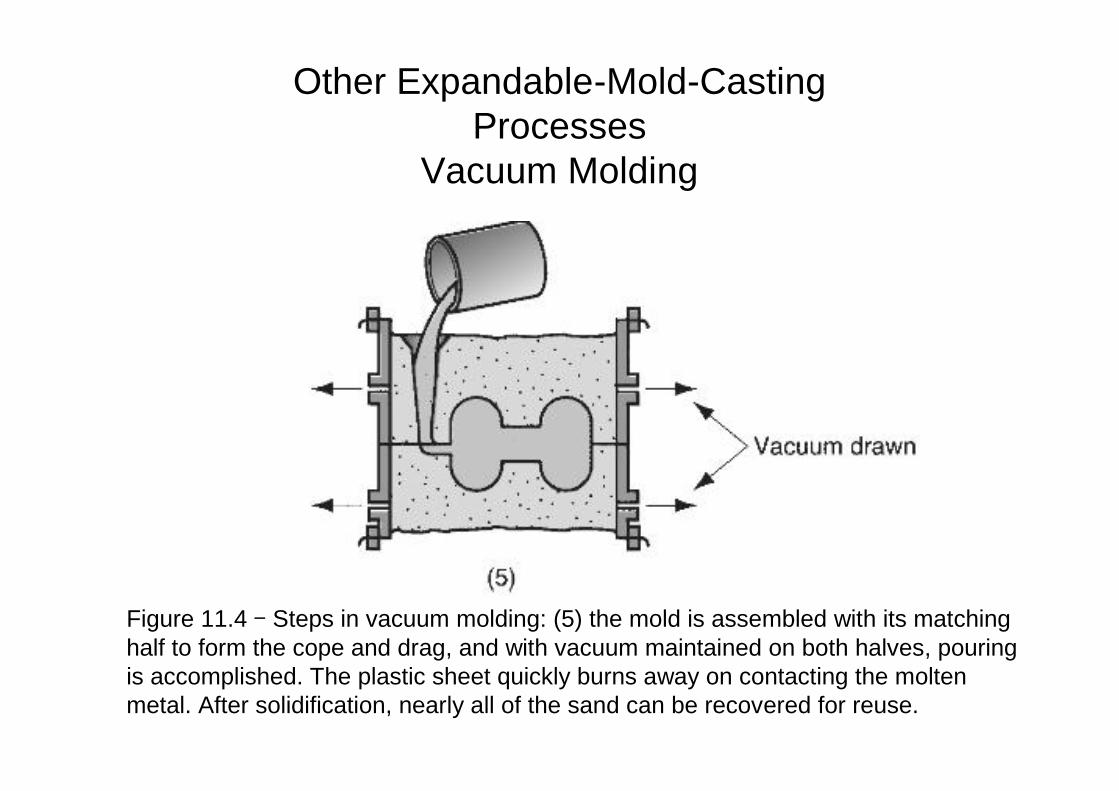
Figure 11.4 - Steps in vacuum molding: (5) the mold is assembled with its matchinghalf to form the cope and drag, and with vacuum maintained on both halves, pouringis accomplished. The plastic sheet quickly burns away on contacting the moltenmetal. After solidification, nearly all of the sand can be recovered for reuse.
Other Expandable-Mold-CastingProcesses
Vacuum Molding
Other Expandable-Mold-CastingProcesses
Vacuum Molding• Advantages of vacuum molding:
– Since no binders are used, sand recovery is almost a perfect process.
– The sand does not require extensive mechanical reconditioningnormally done when binders are used in the molding sand.
– Since no water is mixed with the sand, moisture-related defects areabsent from the product.
• Disadvantages are:
– It is relatively slow.
– Not readily adaptable to mechanization.
Other Expandable-Mold-CastingProcesses
Expanded Polystyrene Process• The expanded polystyrene process uses a mold of sand packed
around a polystyrene foam pattern, which vaporizes when themolten metal is poured into the mold.
• Also known as: lost-foam process, lost pattern process,evaporative-foam process, and full-mold process.
• The polystyrene pattern includes the sprue, risers, gating system,and may contain internal cores (if needed), thus eliminating theneed for a separate core in the mold.
• Since the foam pattern itself becomes the cavity in the mold,considerations of draft and parting lines can be ignored.
• The mold does not have to be opened into cope and drag sections.
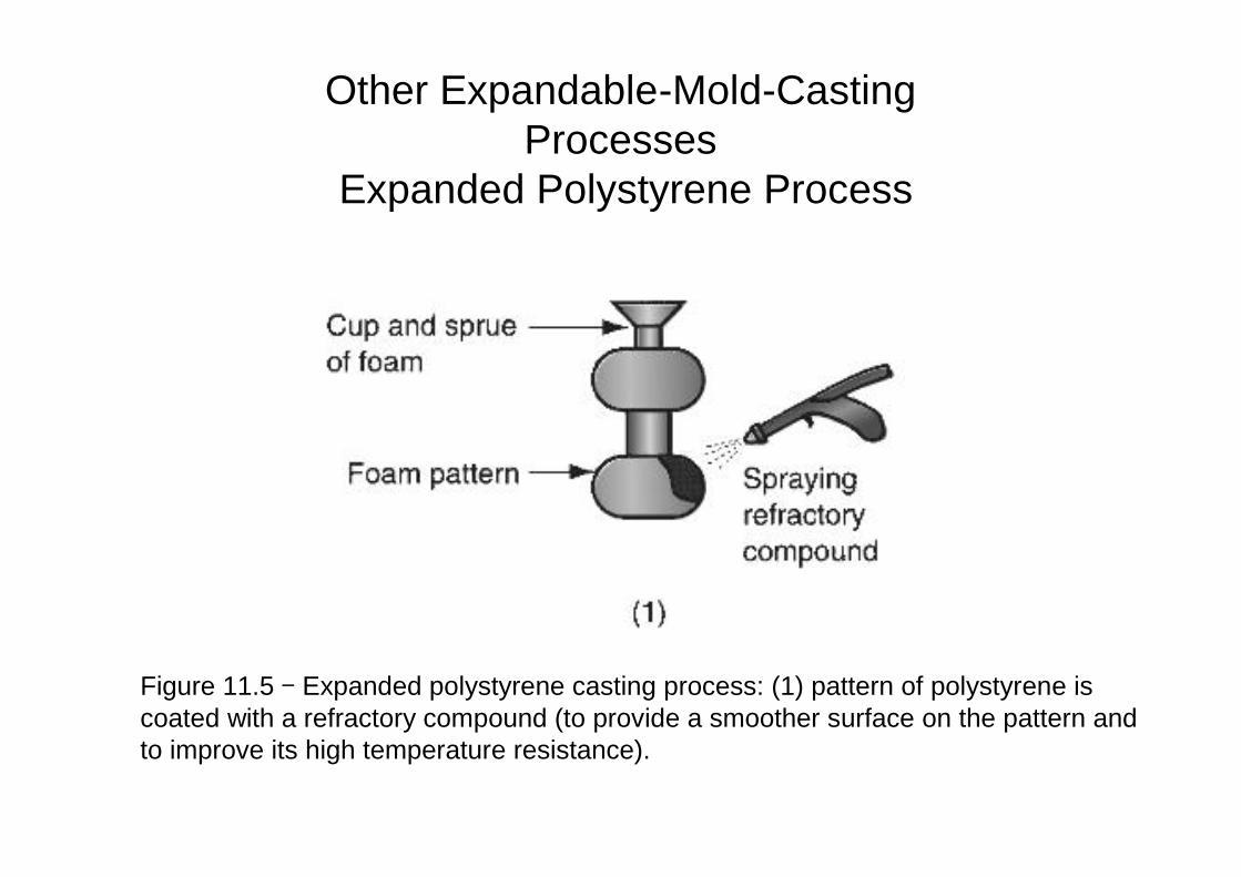
Figure 11.5 - Expanded polystyrene casting process: (1) pattern of polystyrene iscoated with a refractory compound (to provide a smoother surface on the pattern andto improve its high temperature resistance).
Other Expandable-Mold-CastingProcesses
Expanded Polystyrene Process
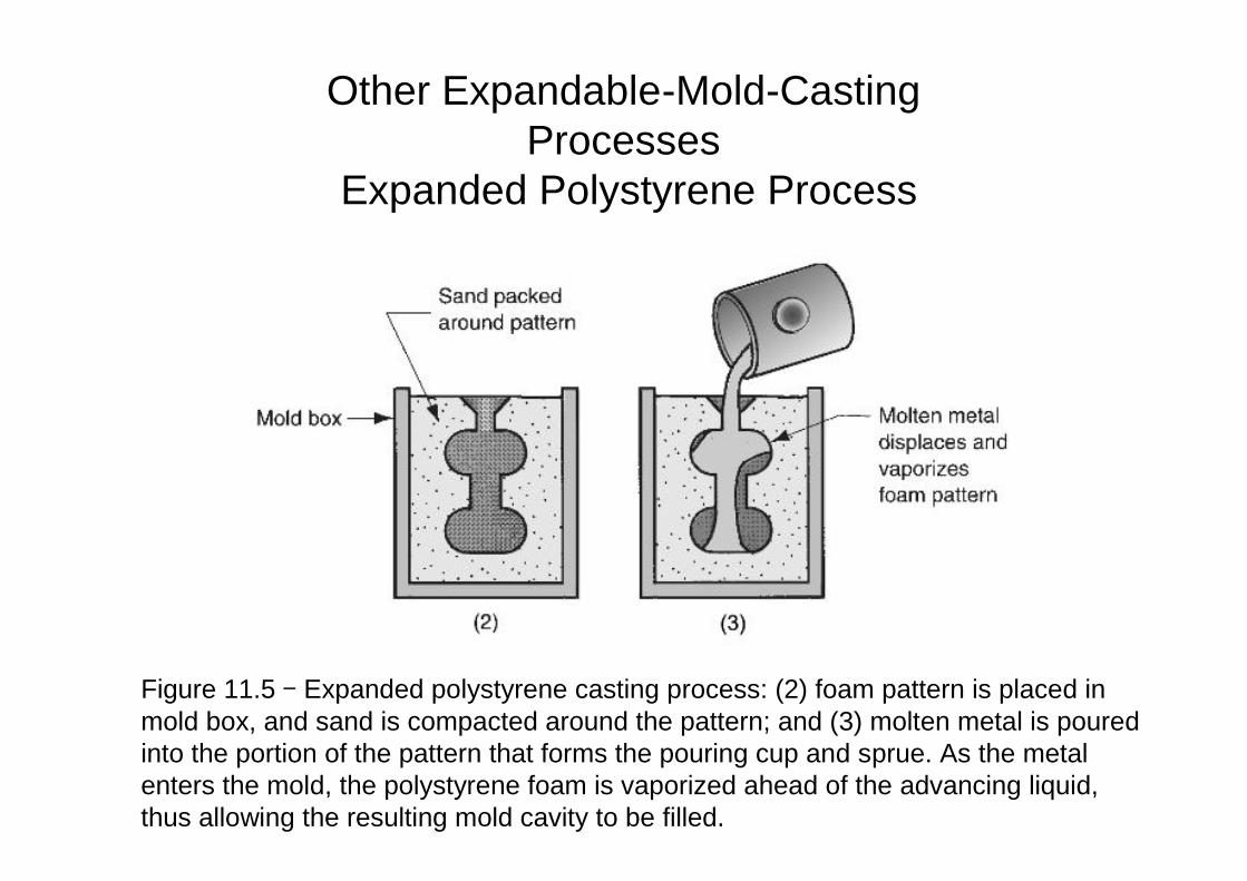
Figure 11.5 - Expanded polystyrene casting process: (2) foam pattern is placed inmold box, and sand is compacted around the pattern; and (3) molten metal is pouredinto the portion of the pattern that forms the pouring cup and sprue. As the metalenters the mold, the polystyrene foam is vaporized ahead of the advancing liquid,thus allowing the resulting mold cavity to be filled.
Other Expandable-Mold-CastingProcesses
Expanded Polystyrene Process
• Advantages of this process include:
– Pattern need not be removed from the mold.
– The steps of incorporating cores and gating and riser system, thepreparation of two mold halves with a proper parting line, allowances,etc, which are necessary for green-sand molding are built into thefoam pattern itself.
• Disadvantage is:
– A new pattern is needed for every casting.
• An example of parts made with the expanded polystyrene processis automobiles engines.
Other Expandable-Mold-CastingProcesses
Expanded Polystyrene Process
Other Expandable-Mold-CastingProcesses
Investment Casting• In investment casting: a pattern made of wax is coated with a
refractory material to make the mold, after which wax is meltedaway prior to pouring the molten metal.
• The term investment comes from one of the less familiardefinitions of the word invest - "to cover completely," this referringto coating of refractory material around the wax pattern.
• It is a precision casting process, as it is capable of makingcastings of high accuracy and intricate detail.
• It dates back to the ancient Egypt, and is also know as the lost-wax process, because the wax pattern is lost from the mold priorto casting.
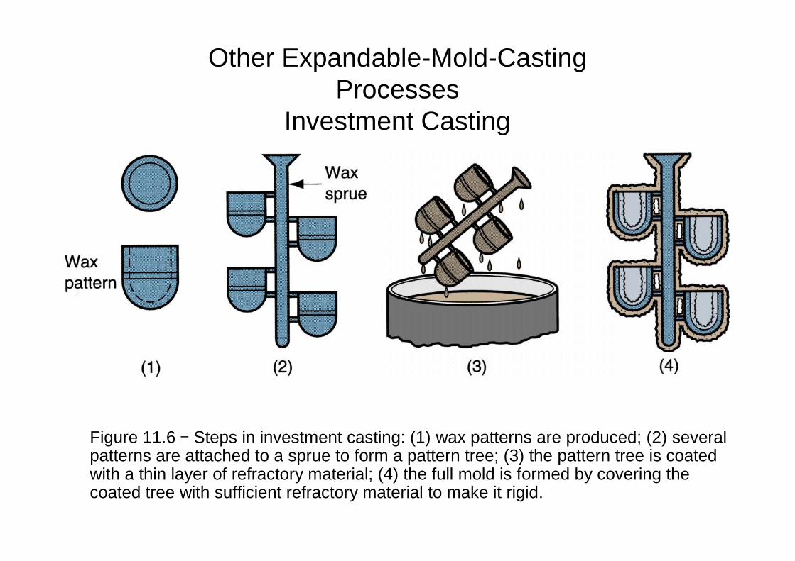
Figure 11.6 - Steps in investment casting: (1) wax patterns are produced; (2) severalpatterns are attached to a sprue to form a pattern tree; (3) the pattern tree is coatedwith a thin layer of refractory material; (4) the full mold is formed by covering thecoated tree with sufficient refractory material to make it rigid.
Other Expandable-Mold-CastingProcesses
Investment Casting
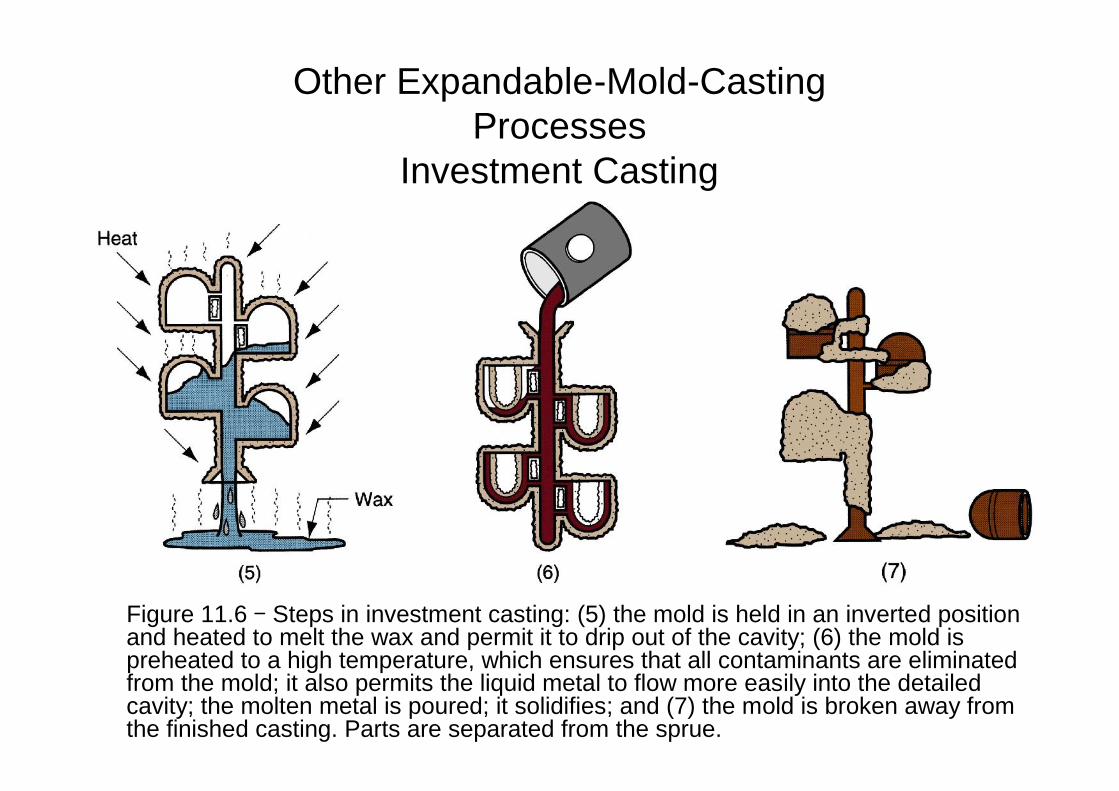
Figure 11.6 - Steps in investment casting: (5) the mold is held in an inverted positionand heated to melt the wax and permit it to drip out of the cavity; (6) the mold ispreheated to a high temperature, which ensures that all contaminants are eliminatedfrom the mold; it also permits the liquid metal to flow more easily into the detailedcavity; the molten metal is poured; it solidifies; and (7) the mold is broken away fromthe finished casting. Parts are separated from the sprue.
Other Expandable-Mold-CastingProcesses
Investment Casting
• Advantages of investment casting are:
– Parts of great complexity can be cast.
– Close dimensional control and good surface finish.
– Wax can usually be recovered for reuse.
– Additional machining is not normally required - this is a net shapeprocess.
• Disadvantage are:
– Since many processing steps are required, it is an expensive process.
– Parts are usually small in size.
• Examples of parts made with this process are blades and jewelry.
Other Expandable-Mold-CastingProcesses
Investment casting
Other Expandable-Mold-CastingProcesses
Plaster-Mold Casting• The Plaster-Mold Casting is similar to sand casting except that
the mold is made of plaster of Paris (gypsum - CaSO4-2H2O) .
• Additives like talc and silica flour are mixed with the plaster tocontrol the setting time, reduce cracking and increase strength.
• In making the mold, plaster and water mixture is poured over aplastic or metal pattern in a flask and allowed to set. Woodenpattern are unsatisfactory due to extended contact with water inthe plaster.
• The fluid consistency permits the plaster mixture to readily flowaround the pattern, capturing its details and surface finish.
• Advantages of this type of casting are:
– Good surface finish and dimensional accuracy.
– Capability to make thin cross-sections in casting.
• Disadvantage are:
– Moisture: long baking times are required to remove moisture.However, too much dehydration will cause the mold to lose itsstrength. A balance must be achieved between theseundesirable alternatives.
– Plaster molds cannot stand the same high temperatures assand molds. They are therefore limited to the casting of low-melting-point alloys.
Other Expandable-Mold-CastingProcesses
Plaster-Mold Casting
Other Expandable-Mold-CastingProcesses
Ceramic-Mold Casting• The Ceramic-Mold Casting is similar to plaster-mold casting
except that the mold is made of refractory ceramic material thatcan withstand higher temperatures than plaster.
• Ceramic molding can be used to cast high-temperature alloyssuch as steels, cast irons, and others.
• Its applications (molds and relatively intricate parts) are similar tothose of plaster-mold casting except for the metals cast.
• Its advantages are also similar to those of plaster-mold casting.
Permanent Mold Casting Processes
• The economic disadvantage of any of theexpendable mold processes is that a new moldis required for every casting.
• In permanent-mold casting, the mold is reusedmany times.
Permanent Mold Casting ProcessesThe Basic Permanent-Mold Process
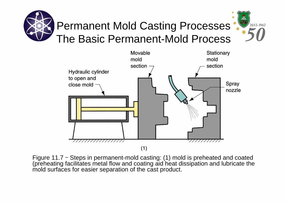
• Permanent-mold casting uses a metal mold constructed of twosections that are designed for easy, precise opening and closing.
• The molds are commonly made of steel or cast iron. Examples ofmetals cast in these molds are Al, Mg, Cu-base alloys and cast-iron. For cast iron however, the mold must be made of refractorymaterial.
• To provide good dimensional accuracy and surface finish, thecavity, with gating system are machined into two halves.
• Metallic cores can be used in permanent molds. However, theyshould be removable, otherwise sand cores can be used. In thelater case, the process is referred to as semipermanent-moldcasting.
• Steps in the basic permanent-mold casting: see next figures.
Permanent Mold Casting ProcessesThe Basic Permanent-Mold Process
Figure 11.7 - Steps in permanent-mold casting: (1) mold is preheated and coated(preheating facilitates metal flow and coating aid heat dissipation and lubricate themold surfaces for easier separation of the cast product.
Permanent Mold Casting ProcessesThe Basic Permanent-Mold Process
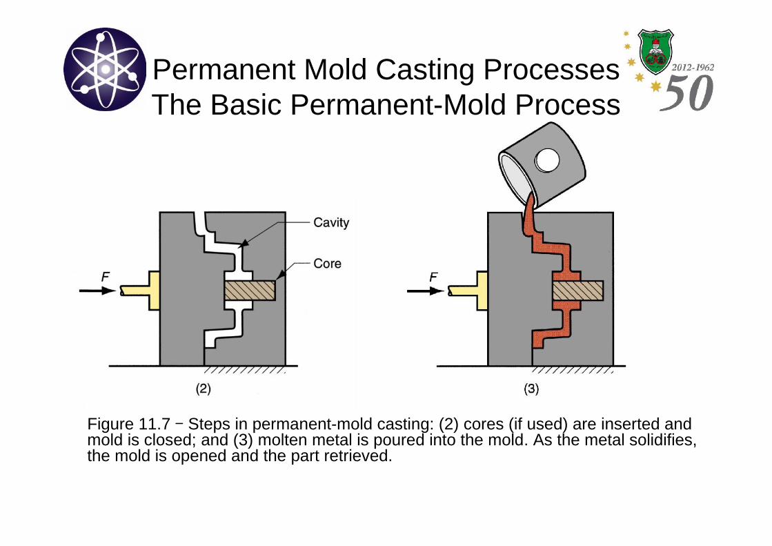
Figure 11.7 - Steps in permanent-mold casting: (2) cores (if used) are inserted andmold is closed; and (3) molten metal is poured into the mold. As the metal solidifies,the mold is opened and the part retrieved.
Permanent Mold Casting ProcessesThe Basic Permanent-Mold Process
• Advantages of permanent-mold casting:
– Good surface finish and close dimensional accuracy.
– More rapid solidification caused by the metal mold results in afiner grain structure, so stronger castings are produced.
• Limitations:
– Generally limited to metals of lower melting points.
– Simple part geometries compared to sand casting because ofthe need to open the mold.
– The expense of the mold.
• Examples of castings are automotive pistons and pump bodies.
Permanent Mold Casting ProcessesDie Casting
• Die casting is a permanent mold casting process inwhich molten metal is injected into mold cavity underhigh pressure (7 to 350 MPa).
• The pressure is maintained during solidification, afterwhich the mold is opened and part is removed.
• The molds in this casting operation are called dies;hence the name die casting.
• The use of high pressure to force the metal into diecavity is the most notable feature that distinguishes thisprocess from others in the permanent mold category.
Permanent Mold Casting ProcessesDie Casting
• Die-casting machines are designed to hold andaccurately close the two mold halves, and keep themclosed while the liquid metal is forced into the cavity.
• There are two main types of die-casting machines,depending on how the molten metal is injected into thecavity:
(1) Hot-chamber.
(2) Cold-chamber.
Permanent Mold Casting ProcessesDie Casting
(1) In hot-chamber machines:
– The metal is melted in a container attached to the machine,and a piston is used to inject the liquid metal under highpressure into the die.
– Production rates up to 500 parts / hour are not uncommon.
– Hot-chamber die casting imposes a special hardship on theinjection system because most of it is submerged into themolten metal.
– Hence, the applications are limited to low melting-point metals(Zn, Sn and Pb) that do not chemically attack plunger and othermechanical components.
Permanent Mold Casting ProcessesDie Casting
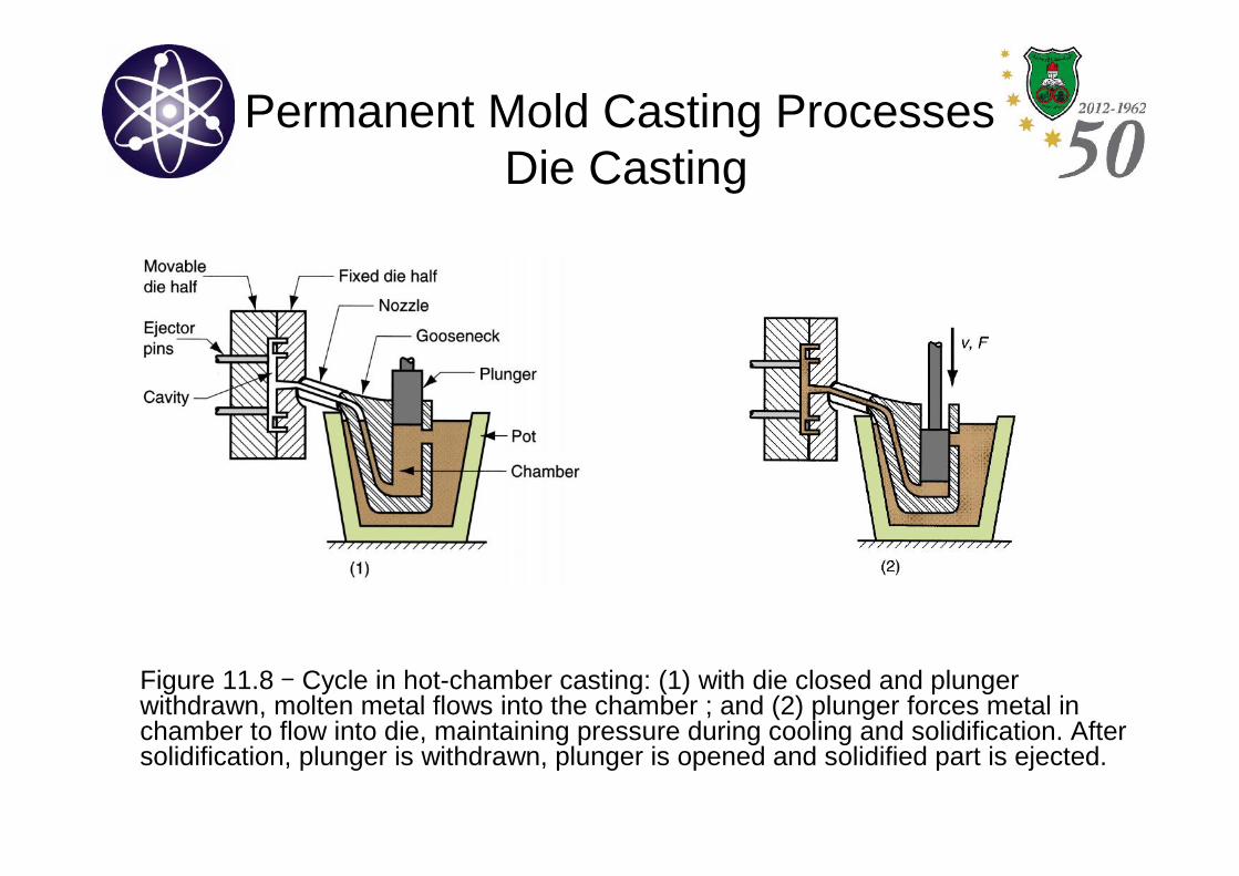
Figure 11.8 - Cycle in hot-chamber casting: (1) with die closed and plungerwithdrawn, molten metal flows into the chamber ; and (2) plunger forces metal inchamber to flow into die, maintaining pressure during cooling and solidification. Aftersolidification, plunger is withdrawn, plunger is opened and solidified part is ejected.
Permanent Mold Casting ProcessesDie Casting
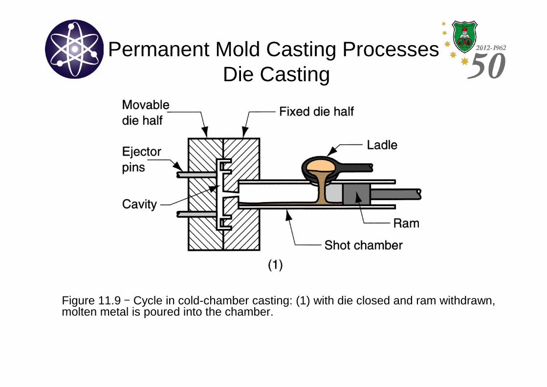
(1) In cold-chamber machines:
– The molten metal is poured into an unheated chamber from anexternal melting container, and a piston is used to inject themetal under high pressure into the die cavity (14 to 140 MPa).
– Compared to hot-chamber machines, cycle rates are notusually as fast because of the need to ladle the liquid metalinto the chamber from an external source (still its highproduction operation).
– Typical for casting: Al, Cu–Zn and Mg alloys.
Permanent Mold Casting ProcessesDie Casting
Figure 11.9 - Cycle in cold-chamber casting: (1) with die closed and ram withdrawn,molten metal is poured into the chamber.
Permanent Mold Casting ProcessesDie Casting
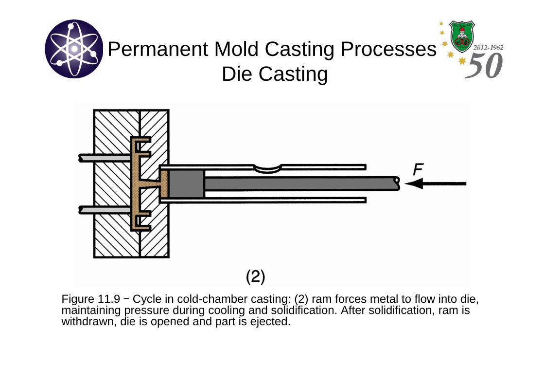
Figure 11.9 - Cycle in cold-chamber casting: (2) ram forces metal to flow into die,maintaining pressure during cooling and solidification. After solidification, ram iswithdrawn, die is opened and part is ejected.
Permanent Mold Casting ProcessesDie Casting
• The molds for die-casting are usually made of tool steel or moldsteel.
• Tungsten and molybdenum with good refractory qualities are alsoused.
• Ejector pins are required to remove the part from the die when itopens.
• Lubricants must be sprayed into the cavity to prevent sticking.
• Vent holes built into the mold (since no natural porosity).
Permanent Mold Casting ProcessesDie Casting
• Advantages of die casting:
– High production rates.
– Economical for large production quantities.
– Close tolerance and good surface finish.
– Thin sections down to 0.5 mm are possible.
– Rapid cooling provides small grain size and good strength to thecasting.
• Limitations:
– Generally limited to metals of lower melting points.
– Part geometry must allow removal from die cavity.
Permanent Mold Casting ProcessesCentrifugal Casting
• Centrifugal casting refers to several castingmethods in which the mold is rotated at high-speed so that centrifugal force distributes themolten metal to the outer regions of the diecavity.
• The group includes:
(1) True centrifugal casting.
(2) Semicentrifugal casting.
(3) Centrifuge casting.
Permanent Mold Casting ProcessesCentrifugal Casting
• In True Centrifugal Casting, molten metal is poured into arotating mold to produce a tubular part.
• Parts made by this process include pipes, tubes and rings.
• In some operations, mold rotation commences after pouring hasoccurred rather than beforehand.
• The high-speed rotation results in centrifugal forces that cause themetal to take the shape of the mold cavity. Thus, the outsideshape of the casting can be round, octagonal, hexagonal, and soon. However, the inside shape of the casting is (theoretically)perfectly round, due to the radially symmetric forces at work.
Permanent Mold Casting ProcessesCentrifugal Casting
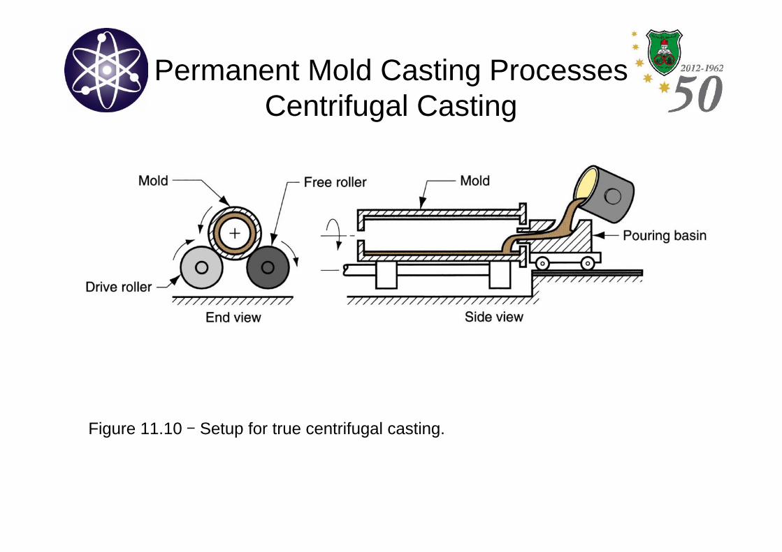
Figure 11.10 - Setup for true centrifugal casting.
Permanent Mold Casting ProcessesCentrifugal Casting
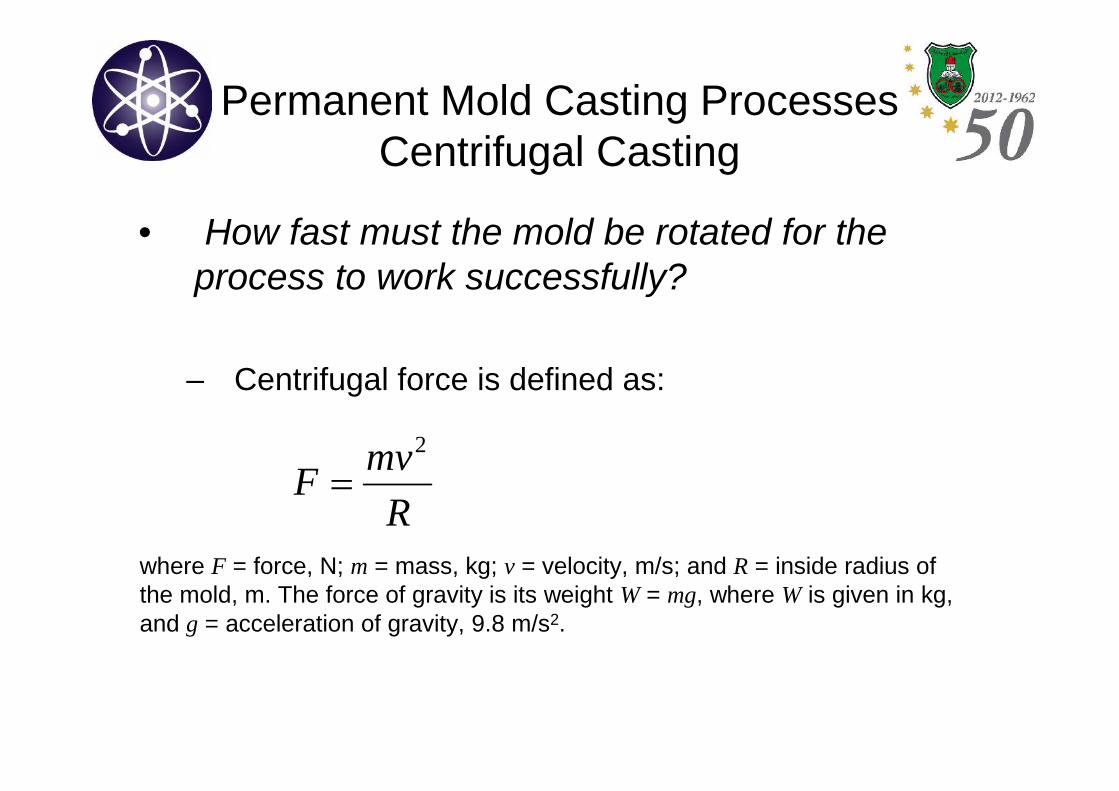
• How fast must the mold be rotated for theprocess to work successfully?
– Centrifugal force is defined as:
R
mvF
2
where F = force, N; m = mass, kg; v = velocity, m/s; and R = inside radius ofthe mold, m. The force of gravity is its weight W = mg, where W is given in kg,and g = acceleration of gravity, 9.8 m/s2.
Permanent Mold Casting ProcessesCentrifugal Casting
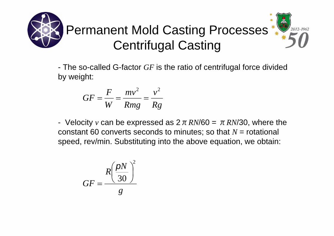
- The so-called G-factor GF is the ratio of centrifugal force dividedby weight:
- Velocity v can be expressed as 2πRN/60 =πRN/30, where theconstant 60 converts seconds to minutes; so that N = rotationalspeed, rev/min. Substituting into the above equation, we obtain:
Rg
v
Rmg
mv
W
FGF
22
g
NR
GF
2
30
Permanent Mold Casting ProcessesCentrifugal Casting
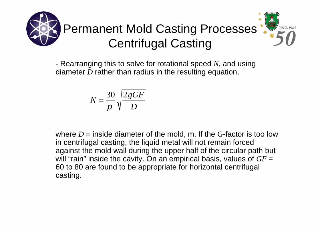
- Rearranging this to solve for rotational speed N, and usingdiameter D rather than radius in the resulting equation,
where D = inside diameter of the mold, m. If the G-factor is too lowin centrifugal casting, the liquid metal will not remain forcedagainst the mold wall during the upper half of the circular path butwill “rain” inside the cavity. On an empirical basis, values of GF =60 to 80 are found to be appropriate for horizontal centrifugalcasting.
D
gGFN
230
Foundry Practice
• In all casting processes, the metal must be heated to the moltenstate to be poured or otherwise forced into the mold. Heating andmelting are accomplished in a furnace.
• The types of furnaces most commonly used in foundries are (1)cupolas, (2) direct fuel-fired furnaces, (3) crucible furnaces, (4)electric-arc furnaces, and (5) induction furnaces.
• Selection of the most appropriate furnace depends on :
– The casting alloy.
– Its melting and pouring temperatures.
– capacity requirements of the furnace.
– costs of investment.
– operation, maintenance, and environmental pollution considerations.
Foundry PracticeFurnaces
• Electric-Arc Furnaces: the charge is melted by heat generatedfrom an electric arc. Power consumption is high, but have highcapacity (23,000–45,000 kg/hr). Used primarily for casting steel.
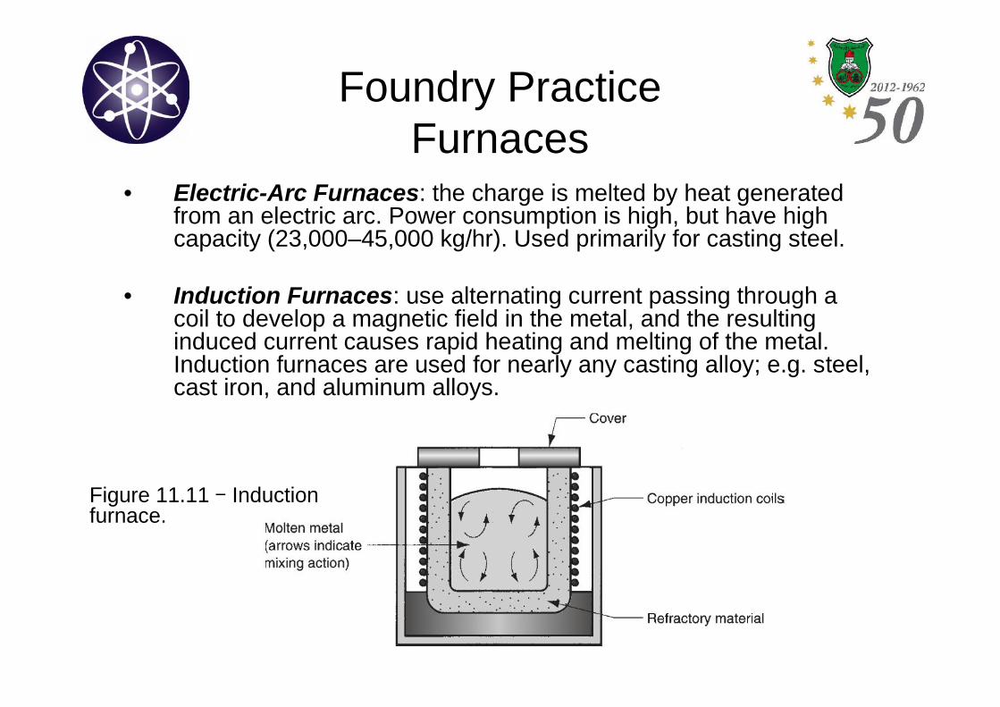
• Induction Furnaces: use alternating current passing through acoil to develop a magnetic field in the metal, and the resultinginduced current causes rapid heating and melting of the metal.Induction furnaces are used for nearly any casting alloy; e.g. steel,cast iron, and aluminum alloys.
Figure 11.11 - Inductionfurnace.
Foundry PracticePouring, Cleaning & Heat Treatment
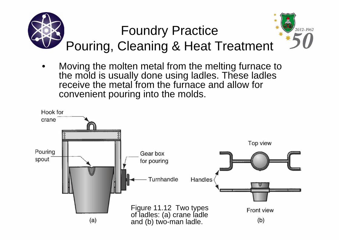
• Moving the molten metal from the melting furnace tothe mold is usually done using ladles. These ladlesreceive the metal from the furnace and allow forconvenient pouring into the molds.
Figure 11.12 Two typesof ladles: (a) crane ladleand (b) two-man ladle.
Foundry PracticePouring, Cleaning & Heat Treatment
• After the casting has solidified and been removed fromthe mold, a number of additional steps are usuallyrequired: (1) trimming, (2) removing the core, (3)surface cleaning, (4) inspection, (5) repair, if required,and (6) heat treatment. Steps (1) to (5) are referred toas “cleaning”.
• Trimming: involves removal of sprues, runners, risers,parting-line flash, fins, chaplets, and any other excessmetal from the cast part.
• Core removal: If cores have been used to cast the part,they must be removed.
Foundry PracticePouring, Cleaning & Heat Treatment
• Surface cleaning: involves removal of sand from thesurface of the casting and otherwise enhancing theappearance of the surface; e.g. using sand blasting.
• Inspection: to detect the presence of defects, andrepairing the castings if possible.
• Heat treatment: often done to enhance the propertiesof the castings, either for subsequent processingoperations such as machining or to bring out thedesired properties for application of the part.
Casting Quality
• There are numerous opportunities for things to gowrong in a casting operation, resulting in quality defectsin the cast product.
• Some of the defects are common to any and all castingprocess. They include: Misruns, Cold shuts, Cold shots,Shrinkage cavities, Microporosity, and Hot tearing.
• Other defects found primarily in sand casting include:Sand blows, Pinholes, Sand wash, Scab, Penetration,Mold shifts, Core shifts, and Mold Cracks.
Casting Quality
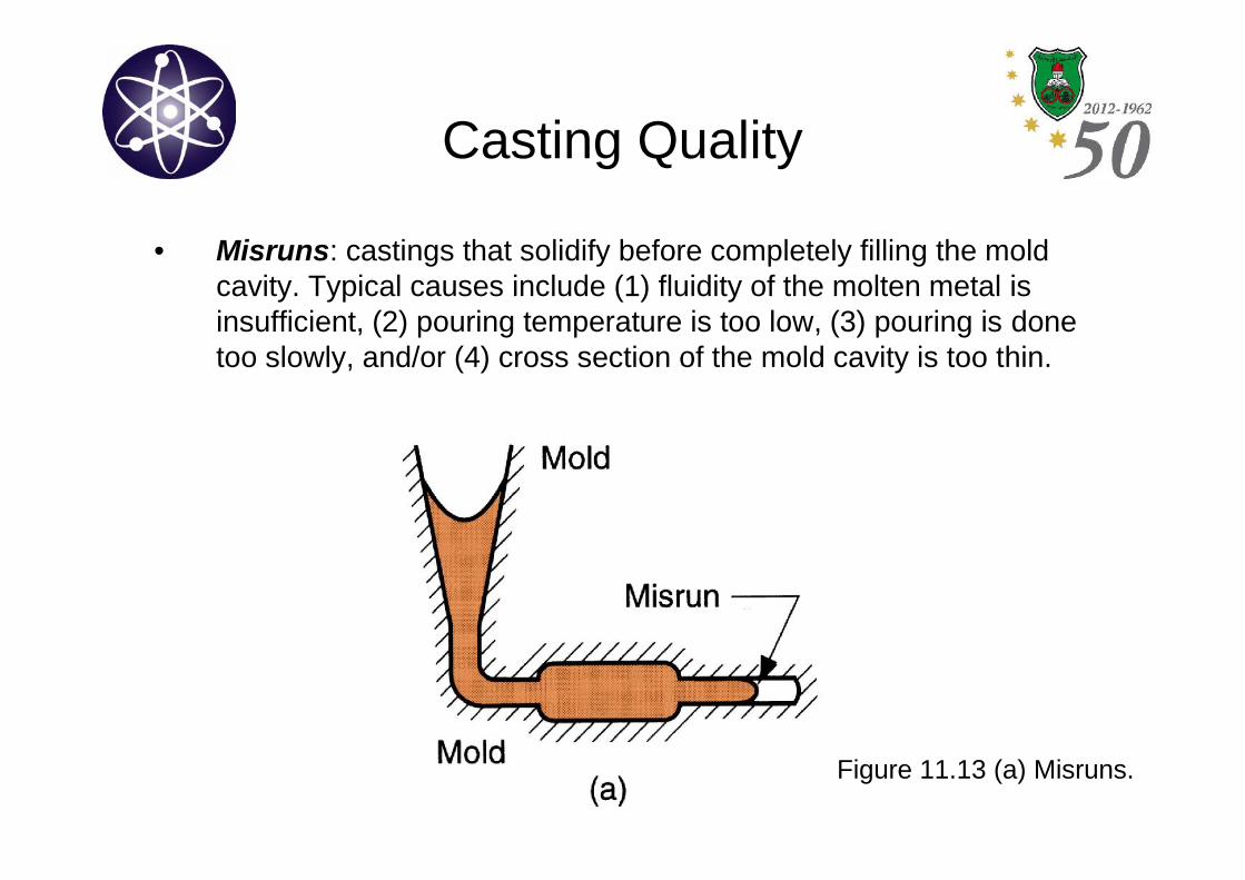
• Misruns: castings that solidify before completely filling the moldcavity. Typical causes include (1) fluidity of the molten metal isinsufficient, (2) pouring temperature is too low, (3) pouring is donetoo slowly, and/or (4) cross section of the mold cavity is too thin.
Figure 11.13 (a) Misruns.
Casting Quality
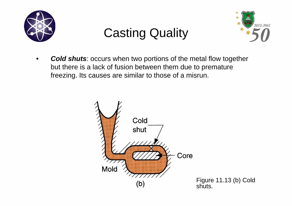
• Cold shuts: occurs when two portions of the metal flow togetherbut there is a lack of fusion between them due to prematurefreezing. Its causes are similar to those of a misrun.
Figure 11.13 (b) Coldshuts.
Casting Quality
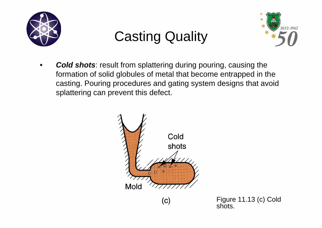
• Cold shots: result from splattering during pouring, causing theformation of solid globules of metal that become entrapped in thecasting. Pouring procedures and gating system designs that avoidsplattering can prevent this defect.
Figure 11.13 (c) Coldshots.
Casting Quality
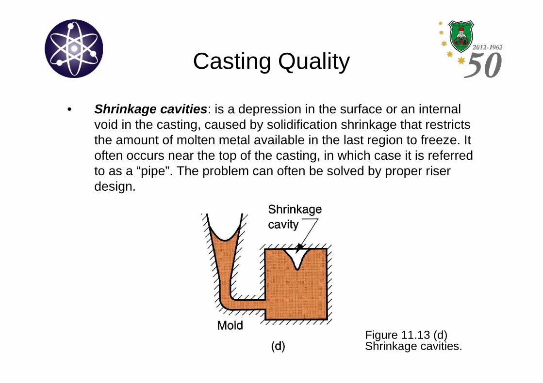
• Shrinkage cavities: is a depression in the surface or an internalvoid in the casting, caused by solidification shrinkage that restrictsthe amount of molten metal available in the last region to freeze. Itoften occurs near the top of the casting, in which case it is referredto as a “pipe”. The problem can often be solved by proper riserdesign.
Figure 11.13 (d)Shrinkage cavities.
Casting Quality
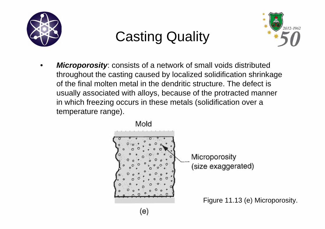
• Microporosity: consists of a network of small voids distributedthroughout the casting caused by localized solidification shrinkageof the final molten metal in the dendritic structure. The defect isusually associated with alloys, because of the protracted mannerin which freezing occurs in these metals (solidification over atemperature range).
Figure 11.13 (e) Microporosity.
Casting Quality
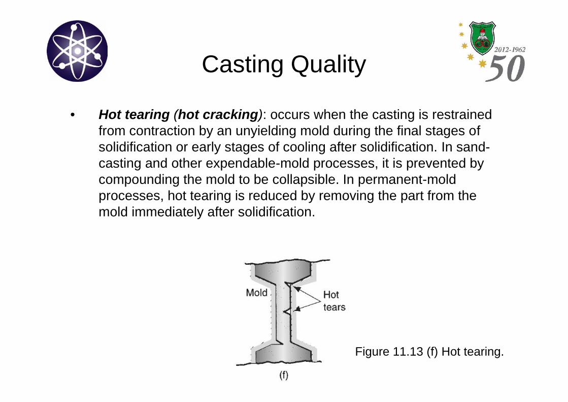
• Hot tearing (hot cracking): occurs when the casting is restrainedfrom contraction by an unyielding mold during the final stages ofsolidification or early stages of cooling after solidification. In sand-casting and other expendable-mold processes, it is prevented bycompounding the mold to be collapsible. In permanent-moldprocesses, hot tearing is reduced by removing the part from themold immediately after solidification.
Figure 11.13 (f) Hot tearing.
Casting Quality
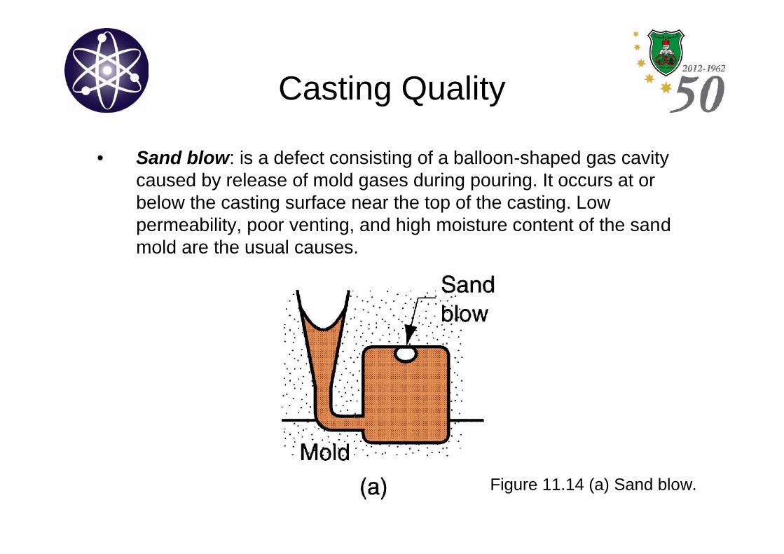
• Sand blow: is a defect consisting of a balloon-shaped gas cavitycaused by release of mold gases during pouring. It occurs at orbelow the casting surface near the top of the casting. Lowpermeability, poor venting, and high moisture content of the sandmold are the usual causes.
Figure 11.14 (a) Sand blow.
Casting Quality
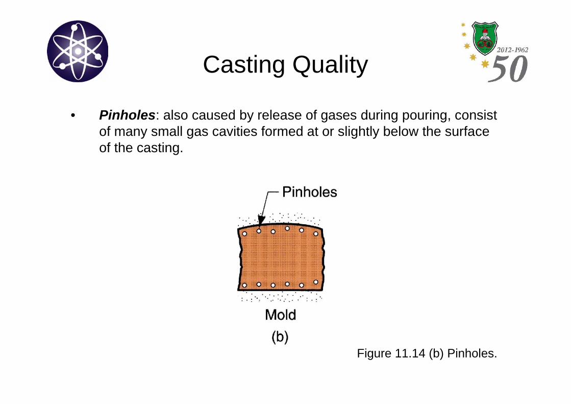
• Pinholes: also caused by release of gases during pouring, consistof many small gas cavities formed at or slightly below the surfaceof the casting.
Figure 11.14 (b) Pinholes.
Casting Quality
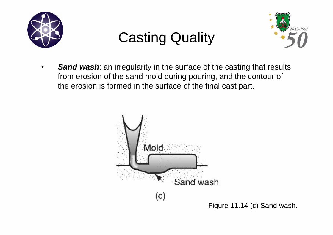
• Sand wash: an irregularity in the surface of the casting that resultsfrom erosion of the sand mold during pouring, and the contour ofthe erosion is formed in the surface of the final cast part.
Figure 11.14 (c) Sand wash.
Casting Quality
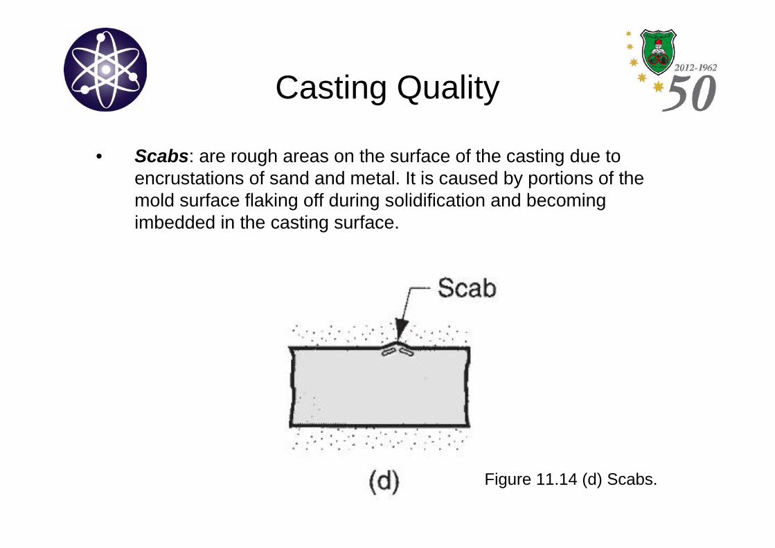
• Scabs: are rough areas on the surface of the casting due toencrustations of sand and metal. It is caused by portions of themold surface flaking off during solidification and becomingimbedded in the casting surface.
Figure 11.14 (d) Scabs.
Casting Quality
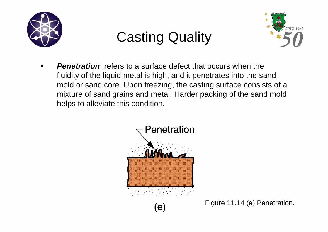
• Penetration: refers to a surface defect that occurs when thefluidity of the liquid metal is high, and it penetrates into the sandmold or sand core. Upon freezing, the casting surface consists of amixture of sand grains and metal. Harder packing of the sand moldhelps to alleviate this condition.
Figure 11.14 (e) Penetration.
Casting Quality
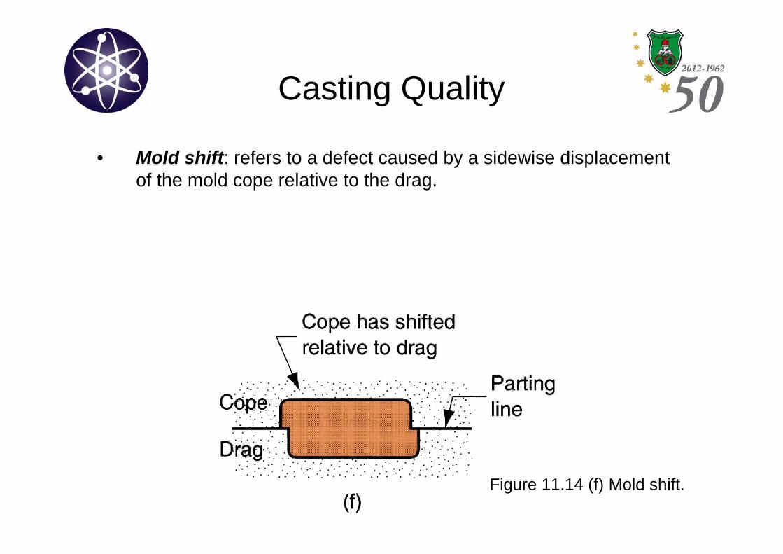
• Mold shift: refers to a defect caused by a sidewise displacementof the mold cope relative to the drag.
Figure 11.14 (f) Mold shift.
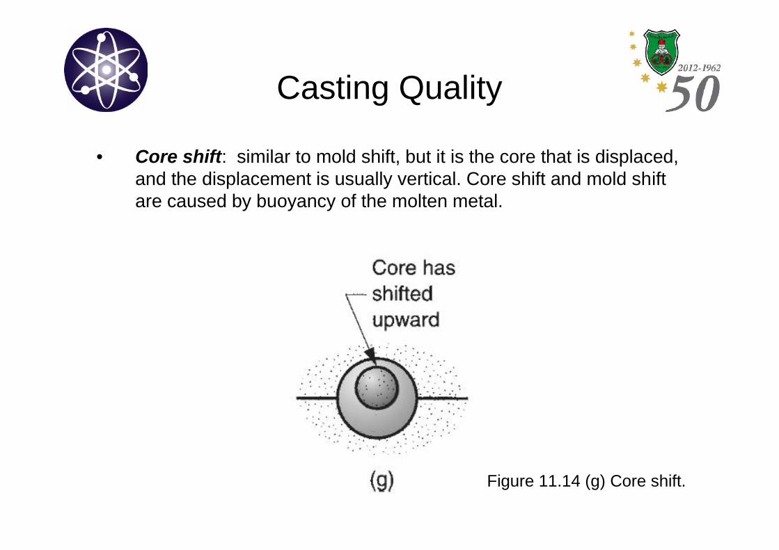
Casting Quality
• Core shift: similar to mold shift, but it is the core that is displaced,and the displacement is usually vertical. Core shift and mold shiftare caused by buoyancy of the molten metal.
Figure 11.14 (g) Core shift.
Casting Quality
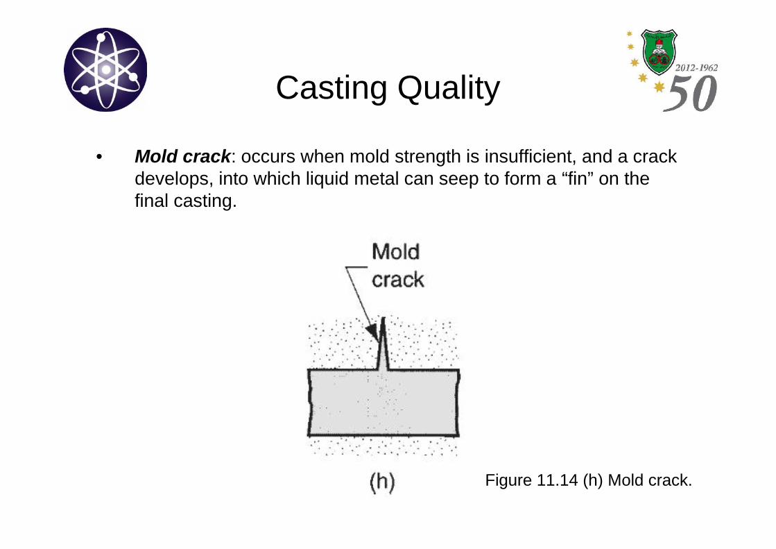
• Mold crack: occurs when mold strength is insufficient, and a crackdevelops, into which liquid metal can seep to form a “fin” on thefinal casting.
Figure 11.14 (h) Mold crack.
Casting Quality
• Inspection methods include:
– Visual inspection to detect defects such as misruns, cold shuts andsevere surface flows.
– Dimensional measurements to ensure that tolerances have been met.
– Metallurgical, chemical, physical and other tests concerned with theinherent quality of the cast material.
Metals for Casting
• Most commercial castings are made of alloys ratherthan pure metals.
• Alloys are generally easier to cast, and the propertiesof the resulting product are better.
• Casting alloys can be classified as:
– Ferrous (steel and cast iron).
– Nonferrous.
Metals for CastingFerrous Casting Alloys
• Cast Iron: is the most important of all casting alloys. The tonnageof cast iron castings is several times that of all other metalscombined.
• There are several types of cast iron:
– Gray cast iron.
– Nodular iron.
– White cast iron.
– Malleable iron.
• Typical pouring temperatures for cast iron are around 1400 ºC,depending on composition.
Metals for CastingFerrous Casting Alloys
• Steel: the mechanical properties of steel make it an attractiveengineering material, and the capability to create complexgeometries makes casting an appealing process. However, greatdifficulties are faced by the foundry specializing in steel:
– The melting point of steel is considerably higher than for most othermetals that are commonly cast.
– The solidification range for low-carbon steels begins at 1540 ºC.
– The pouring temperature required for steel is very high (1650 ºC).
– Due to high pouring temperature, steel readily oxidizes, so specialprocedures must be used during melting and pouring to isolate themolten metal from air.
– Molten steel has relatively poor fluidity, and this limits the design ofthin sections in components cast out of steel.
Metals for CastingFerrous Casting Alloys
• However, several characteristics of steel castings makeit worth the effort to solve these problems:
– Tensile strength is higher than for most other castingmetals, ranging upward from about 410 MPa.
– Steel castings have better toughness than most othercasting alloys.
– The properties of steel castings are isotropic; strength isvirtually the same in all directions.
– Steel castings can be readily welded without significantloss of strength.
Metals for CastingNonferrous Casting Alloys
• Aluminum alloys: generally considered to be verycastable.
– The melting point of pure aluminum is 660 ºC, so pouringtemperatures for Al casting alloys are low compared to castiron and steel.
– Their properties make them attractive for castings: light weight,wide range of strength properties attainable through heattreatment, and ease of machining.
• Magnesium alloys:
– The lightest of all casting metals.
– Other properties include corrosion resistance, as well as highstrength-to-weight and stiffness-to-weight ratios.
Metals for CastingNonferrous Casting Alloys
• Copper alloys: include bronze (Cu–Sn), brass (Cu–Zn), and aluminum bronze.
– Good corrosion resistance.
– Attractive appearance.
– Good bearing (strength) properties.
– However, the high cost of Cu is a limitation on the use of itsalloys.
• Tin-based alloys: are easy to cast and they have goodcorrosion resistance. However, they have poormechanical strength.
Metals for CastingNonferrous Casting Alloys
• Zinc alloys: commonly used in die-casting.
– Low melting point and good fluidity, making it highly castable.
– Its major weakness is low creep strength, so its castingscannot be subjected to prolonged high stresses.
• Nickel alloys:
– Good hot strength and corrosion resistance, which make themsuited to high-temperature applications; e.g. jet engines.
– Ni alloys however, have a high melting point, so not easy tocast.
Metals for CastingNonferrous Casting Alloys
• Titanium alloys: commonly used in die-casting.
– Corrosion resistant and possess high strength-to-weight ratios.
– However, they are difficult to cast as Ti has a high melting point,low fluidity, and a tendency to oxidize at high temperatures.
Product Design Considerations
• In casting, certain guidelines should be followed tofacilitate production of the part and avoid many of thedefects discussed earlier.
• These include: (1) Geometric Simplicity, (2) Corners,(3) Section Thicknesses, (4) Draft, (5) Use of Cores,(6) Dimensional Tolerance and Surface Finishesand (7) Machining Allowances.
Product Design Considerations
(1) Geometric Simplicity:
- Simplifying the part design will improve its castability. Avoidingunnecessary complexities simplifies mold making, reduces theneed for cores, and improves the strength of the casting.
(2) Corners:
- Sharp corners and angles should be avoided, because they aresources of stress concentrations and may cause hot tearing andcracks in the casting. Generous fillets should be designed oninside corners, and sharp edges should be blended.
Product Design Considerations
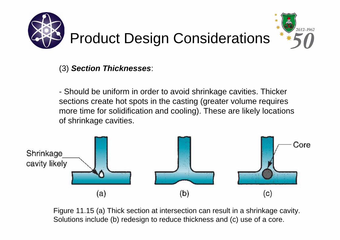
(3) Section Thicknesses:
- Should be uniform in order to avoid shrinkage cavities. Thickersections create hot spots in the casting (greater volume requiresmore time for solidification and cooling). These are likely locationsof shrinkage cavities.
Figure 11.15 (a) Thick section at intersection can result in a shrinkage cavity.Solutions include (b) redesign to reduce thickness and (c) use of a core.
Product Design Considerations
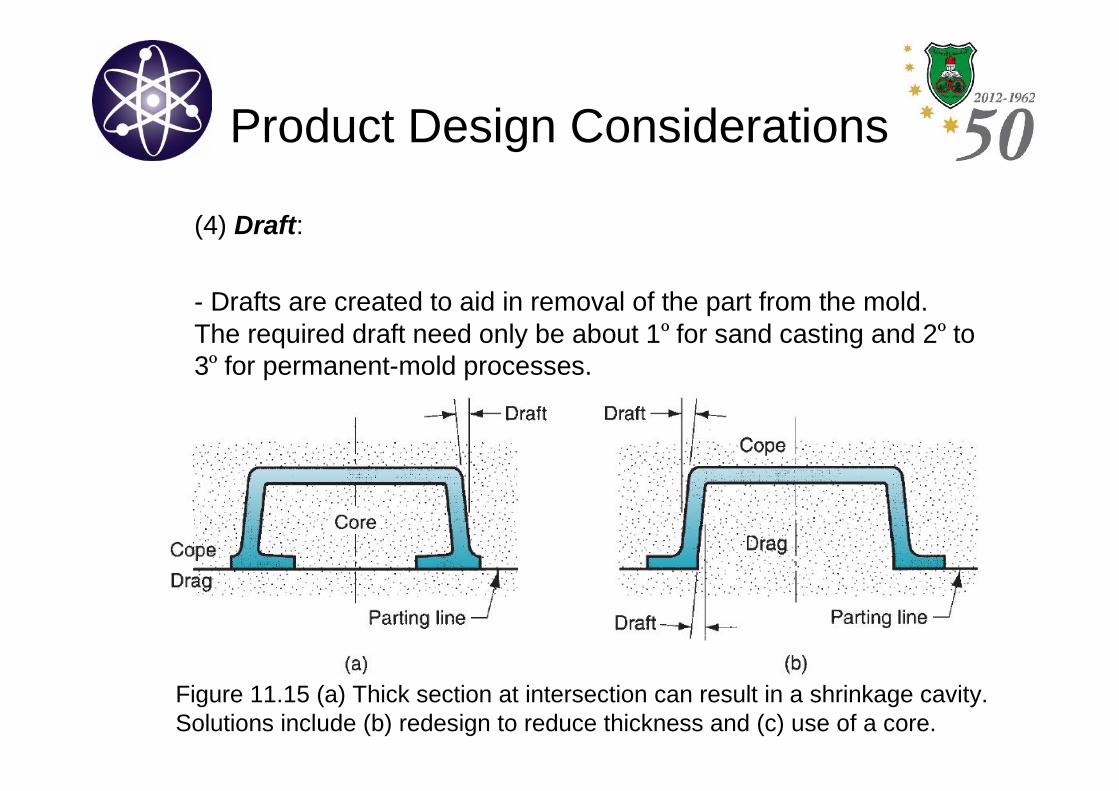
(4) Draft:
- Drafts are created to aid in removal of the part from the mold.The required draft need only be about 1º for sand casting and 2º to3º for permanent-mold processes.
Figure 11.15 (a) Thick section at intersection can result in a shrinkage cavity.Solutions include (b) redesign to reduce thickness and (c) use of a core.
Product Design Considerations
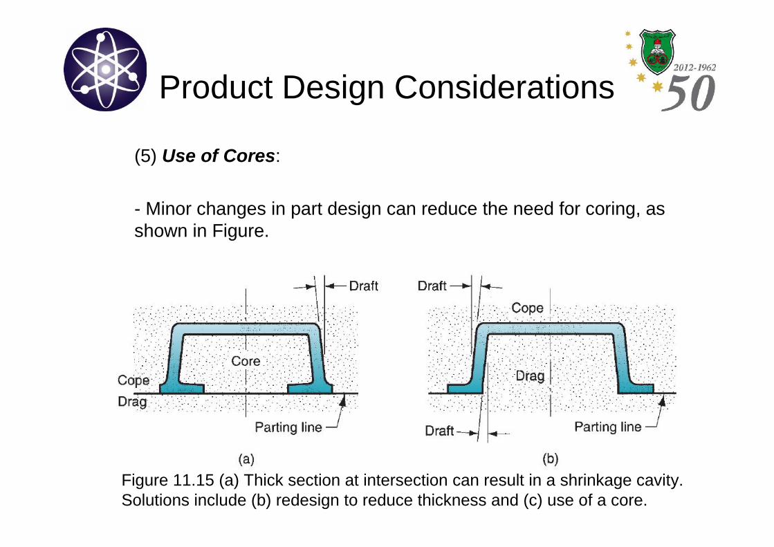
(5) Use of Cores:
- Minor changes in part design can reduce the need for coring, asshown in Figure.
Figure 11.15 (a) Thick section at intersection can result in a shrinkage cavity.Solutions include (b) redesign to reduce thickness and (c) use of a core.
Product Design Considerations
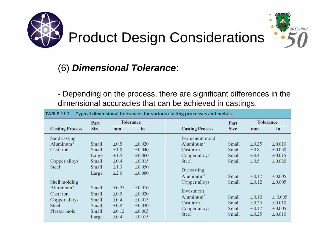
(6) Dimensional Tolerance:
- Depending on the process, there are significant differences in thedimensional accuracies that can be achieved in castings.
Product Design Considerations
(6) Surface Finish:
- Typical surface roughness achieved in sand casting is around 6μm. Similarly poor finishes are obtained in shell molding, whileplaster-mold and investment casting produce much betterroughness values: 0.75μm.
- Among the permanent-mold processes, die casting is noted forgood surface finishes at around 1μm
Product Design Considerations
(7) Machining Allowances:
- Tolerances achievable in many casting processes are insufficientto meet functional needs in many applications (sand casting is theworst). So machining is required.
- Therefore, additional material, called the machining allowance, isleft on the casting for machining those surfaces where necessary.Typical machining allowances for sand castings range between1.5 and 3 mm
Related Documents