Journal of University of Babylon, Engineering Sciences, Vol.(26), No.(4): 2018. 104 Manufacturing A Refrigerator with Heat Recovery Unit Mustafa Mohammed Kadhim Department of Dairy Technology, College of Food Sciences, Al-Qasim Green University [email protected] Abstract This study aims to exploite the rejected heating energy from condenser and benefit from it to reheat the foods and other materials. It can also be employed to improve the coefficient of performance of a refrigerator at the same time by using approximately the same consumption electrical energy used to operate the compressor and refrigerator in general. This idea has been implemented by manufacturing of a refrigerator with using additional part has the same metal and condenser pipe diameters but its surface area does not exceed 40% from total surface area of the condenser and its design as an insulated cabinet from all sides to prevent heat leakage through it and located between the compressor and the condenser. Small electrical fan has been added inside this cabinet to provide a suitable air circulation and a homogenous temperature distribution inside the cabinet space. It is expected that the super heating energy of refrigerant (R134a) which comes out of the compressor would be removed inside this cabinet and this insist to condensate the refrigerant (cooling fluid) with a rate higher than that used in the normal refrigerator only. Three magnetic valves have been used in order to control the refrigerant flow in state of operation the refrigerator only or to gather with heating cabinet. To measure the temperatures at each process of the simple vapor compression refrigeration cycle, nine temperature sensors at input and output of each compressor, condenser and an evaporator in additional to input of cabinet and inside it and on evaporator surface have been provided. Five pressure gages have been used to measure the value of pressure and compare it for the two states of operation. The consumption of electrical energy can be calculated by adding an ammeter and a voltmeter and compare between the consumption energy of both states. The obtained results show that there is an improvement in the coeffecient of performance in state of operation the refrigerator with heat recovery cabinet by 20% more than that of the operation of refrigerator only. This improvement is due to the reduction in the condenser exit temperature by 4 to 6 C˚, and the super heat removing process in reheating cabinet. The temperature of the cabinet reachs to 60 C˚ which is a sufficient for the food heating. A small amount of refrigerant pressure reduction due to these additions, and its effect on the preformace of the refrigerator may be not considerable. Key words: Refrigerator, Heat recovery cabinet, Refrigeration cycle, Coefficient of performance ˚ ˚ . brought to you by CORE View metadata, citation and similar papers at core.ac.uk provided by Journals of University of Babylon

Welcome message from author
This document is posted to help you gain knowledge. Please leave a comment to let me know what you think about it! Share it to your friends and learn new things together.
Transcript

Journal of University of Babylon, Engineering Sciences, Vol.(26), No.(4): 2018.
104
Manufacturing A Refrigerator with Heat Recovery Unit
Mustafa Mohammed Kadhim
Department of Dairy Technology, College of Food Sciences, Al-Qasim Green University
Abstract This study aims to exploite the rejected heating energy from condenser and benefit from it to reheat
the foods and other materials. It can also be employed to improve the coefficient of performance of a
refrigerator at the same time by using approximately the same consumption electrical energy used to
operate the compressor and refrigerator in general. This idea has been implemented by manufacturing of a
refrigerator with using additional part has the same metal and condenser pipe diameters but its surface area
does not exceed 40% from total surface area of the condenser and its design as an insulated cabinet from all
sides to prevent heat leakage through it and located between the compressor and the condenser. Small
electrical fan has been added inside this cabinet to provide a suitable air circulation and a homogenous
temperature distribution inside the cabinet space. It is expected that the super heating energy of refrigerant
(R134a) which comes out of the compressor would be removed inside this cabinet and this insist to
condensate the refrigerant (cooling fluid) with a rate higher than that used in the normal refrigerator only.
Three magnetic valves have been used in order to control the refrigerant flow in state of operation the
refrigerator only or to gather with heating cabinet. To measure the temperatures at each process of the
simple vapor compression refrigeration cycle, nine temperature sensors at input and output of each
compressor, condenser and an evaporator in additional to input of cabinet and inside it and on evaporator
surface have been provided. Five pressure gages have been used to measure the value of pressure and
compare it for the two states of operation. The consumption of electrical energy can be calculated by
adding an ammeter and a voltmeter and compare between the consumption energy of both states. The
obtained results show that there is an improvement in the coeffecient of performance in state of operation
the refrigerator with heat recovery cabinet by 20% more than that of the operation of refrigerator only. This
improvement is due to the reduction in the condenser exit temperature by 4 to 6 C˚, and the super heat
removing process in reheating cabinet. The temperature of the cabinet reachs to 60 C˚ which is a sufficient
for the food heating. A small amount of refrigerant pressure reduction due to these additions, and its effect
on the preformace of the refrigerator may be not considerable.
Key words: Refrigerator, Heat recovery cabinet, Refrigeration cycle, Coefficient of performance
˚
˚
.
brought to you by COREView metadata, citation and similar papers at core.ac.uk
provided by Journals of University of Babylon

Journal of University of Babylon, Engineering Sciences, Vol.(26), No.(4): 2018.
105
1. Introduction Air conditioning apparatuses have been become one of the most important
requirements of the daily life, especially in the zones which have hot weather in order to
provide the best conditions for the people. Moreover They are widely used in cooling
and saving foods and in the different industrial applications.
The development in all fields of life made the designers, air conditioning and
refrigeration apparatuses manufacturers take into consideration two essential factors: the
first factor is energy conservation and how to save on it and how to use it in other fields
additional to the cooling and refrigeration processes such as heating as example, the
second factor is economic benefit for work to obtain high performance with less cost.
As air conditioning and refrigeration systems have been used widely in our daily
life , therefore, it is necessary to take into account these systems and the suitable methods
to avoid energy consumption.
The energy consumed in operating the cooling apparatuses represents large part of
the total consumption energy in houses and other locations which depend in their air
condition on cooling apparatuses. The percentage of the consumption energy for this
purpose reached to 63% from the overall consumption of the houses energy, therefore,
many studies attempted to investigate the methods of reduction and benefit from this
consumption energy on cooling purpose and using it in the best form. One of these
studies is proposed by (SADC,1999) which discussed the heat recovery by using the
cooling cycle as heat pump arrangement with closed cycle behavior in which the fresh
out door air flowed through pipes of condenser coil has been heated and provided to a
certain room. Then the remained heat in the returned air has been used in evaporating the
refrigerant through the evaporator coil before air expelling and then the principle of
energy conservation is applied in cooling cycle. (Thomas, 2003) explained the possibility
of heat recovery from the condenser cooling water in water refrigeration chiller units and
benefit from it to heat or reheat the internal domestic water in hospitals by using
dedicated heat recovery chiller (DHRC) which contain heat exchanger in which heat
transfers between condenser water and required domestic water. In additional to heat
exchanger the system also includes water collector vessel and circulation pumps. This
study explains coefficient of performance improvement of refrigeration units when the
heat recovery exchanger is operated with a high percentage. This study also deals with
the reduction in energy consumption of compressor unit. After a few years (SADC,
2006)used Ethylene glycol fluid as a refrigerant in a closed cycle which contains two
heat exchangers: one of them has been used to absorb heat from the outside air and
cooling it and the other one has been used to absorb heat from exhaust air before exit to
external surround. Heat transfer efficiency was not less than 60% and circulation pump
has been used between these heat exchangers. In other hand heat recovery unit has been
used by (Michael, 2008) to recover the super heat from the refrigerant R22 in split air
conditioner unit and use it to heat the required air for other purposes. This study explains
the possibility of keeping 15% - 18% of the required energy to water heating. In 2011,
[Ali abdul Whaab Ismiael] discuses the possibility of heat recovry from the superheated
vapour (R22) in the discharge of compressor of the simple vapor compression
refrigeration cycle for a purpose of using it in heating process, i.e. operating as heat
pump.

Journal of University of Babylon, Engineering Sciences, Vol.(26), No.(4): 2018.
106
Generally the simple vapor compression refrigeration cycle consists of the
following basic parts: compressor, condenser, expansion valve or capillary tube and
evaporator. The condenser and evaporator are heat exchangers of different forms. In
evaporator heat transfers from foods and other materials to the cooling fluid while in
condenser the heating energy transfers from cooling fluid to the air surrounding it. To do
both processes in evaporator and condenser there is work should be done in compressor
or electrical energy consumed to operate the compressor.
Note that there is a continuous loss in the heat energy through the condenser to the
external surrounding. Therefore, the idea of this research aims to exploite the rejected
heating energy from condenser and benefit from it to reheat the foods and other materials
and improving the coefficient of performance of refrigerator at the same time by using
approximately the same consumption electrical energy to operate the compressor and
refrigerator in general. This idea has been implimented by manufacturing of refrigerator
with heat recovery unit for food heating, and this refrigerator is charged by refrigerant
R134a as it is shown in the figure (1).
Fig. (1): Refrigerator with Heat Recovery System and Main Sensors
2. Simple Vapor Compression Refrigeration Cycle To understand the way of adding a heat recovery cabinet and its effect on the
compression refrigeration cycle, it is necessary to investigate the simple vapor
compression refrigeration cycle in details (Stoecker, 1982).
Refrigeration cycle with compression refrigeration system consists of four essential
parts which are respectively evaporator, compressor, condenser and expansion valve as
shown in figures (2 and 3), and this cycle operates at saturated conditions for refrigerant
which is charged in the refrigeration cycle. This cycle is a theoretical cycle assumed that
refrigerant vapor exits from evaporator as a dry saturated vapor and enters to the
compressor at a saturated temperature of the evaporator pressure. The condensate

Journal of University of Babylon, Engineering Sciences, Vol.(26), No.(4): 2018.
107
refrigerant leaves the condenser at a saturated state and is saturated liquid at a saturated
temperature of the condenser pressure. The compressor do to draw refrigerant vapor
which is in dry saturated state from evaporator and compressed it from the evaporator
pressure to the condenser pressure. In this state external work has been added to the
refrigerant vapor with constant entropy. The refrigerant vapor exits from compressor as
super heated vapor at a high temperature and enters to condenser to lose super heat and
converts to saturated vapor with a constant pressure and then loses the latent heat to
convert it to saturated liquid with a constant pressure also. The connected pipe from
compressor to condenser is called the discharge line and the connected pipe from
evaporator to compressor is called the suction line. The refrigerant exits from condenser
as a saturated liquid and enters to the device of expansion which is a capillary tube in
small refrigeration units and expansion valve for large refrigeration units. Expansion
device job is to reduce the pressure and the temperature of the refrigerant. The refrigerant
exits from the expansion device as a mixture of liquid and vapor (wet vapor). This wet
vapor enters the evaporator to absorb an amount of heat from the evaporated space (the
latent heat of evaporation) to convert it to a dry saturated vapor with a constant pressure
and a constant temperature and exits to suction line oriented to the compressor. The
above basic processes are the origin for each actual refrigeration cycle has mechanical
compression process to refrigerant vapor by compressor.
Fig. (2): Diagram of Simple Vapor Compression Refrigeration Cycle
Fig.(3): Layout of Simple Vapor Compression Refrigeration Machine
Journal of University of Babylon, Engineering Sciences, Vol.(26), No.(4): 2018.
108
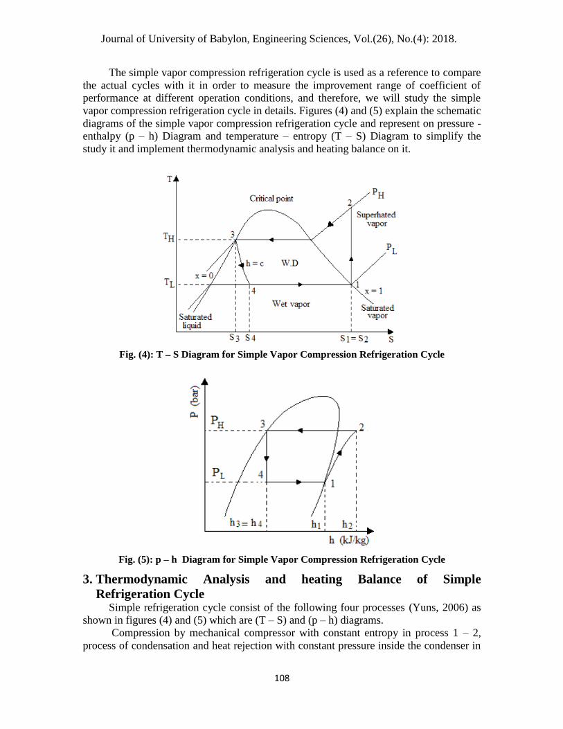
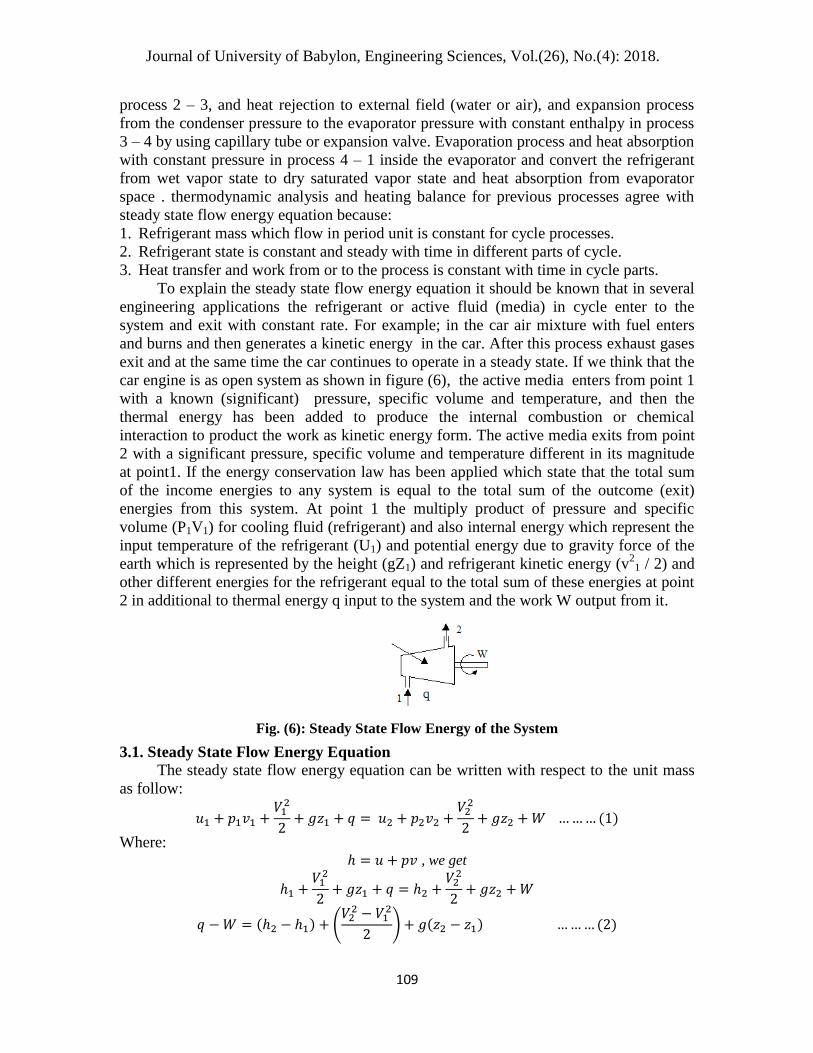
The simple vapor compression refrigeration cycle is used as a reference to compare
the actual cycles with it in order to measure the improvement range of coefficient of
performance at different operation conditions, and therefore, we will study the simple
vapor compression refrigeration cycle in details. Figures (4) and (5) explain the schematic
diagrams of the simple vapor compression refrigeration cycle and represent on pressure -
enthalpy (p – h) Diagram and temperature – entropy (T – S) Diagram to simplify the
study it and implement thermodynamic analysis and heating balance on it.
Fig. (4): T – S Diagram for Simple Vapor Compression Refrigeration Cycle
Fig. (5): p – h Diagram for Simple Vapor Compression Refrigeration Cycle
3. Thermodynamic Analysis and heating Balance of Simple
Refrigeration Cycle Simple refrigeration cycle consist of the following four processes (Yuns, 2006) as
shown in figures (4) and (5) which are (T – S) and (p – h) diagrams.
Compression by mechanical compressor with constant entropy in process 1 – 2,
process of condensation and heat rejection with constant pressure inside the condenser in
Journal of University of Babylon, Engineering Sciences, Vol.(26), No.(4): 2018.
109
process 2 – 3, and heat rejection to external field (water or air), and expansion process
from the condenser pressure to the evaporator pressure with constant enthalpy in process
3 – 4 by using capillary tube or expansion valve. Evaporation process and heat absorption
with constant pressure in process 4 – 1 inside the evaporator and convert the refrigerant
from wet vapor state to dry saturated vapor state and heat absorption from evaporator
space . thermodynamic analysis and heating balance for previous processes agree with
steady state flow energy equation because:
1. Refrigerant mass which flow in period unit is constant for cycle processes.
2. Refrigerant state is constant and steady with time in different parts of cycle.
3. Heat transfer and work from or to the process is constant with time in cycle parts.
To explain the steady state flow energy equation it should be known that in several
engineering applications the refrigerant or active fluid (media) in cycle enter to the
system and exit with constant rate. For example; in the car air mixture with fuel enters
and burns and then generates a kinetic energy in the car. After this process exhaust gases
exit and at the same time the car continues to operate in a steady state. If we think that the
car engine is as open system as shown in figure (6), the active media enters from point 1
with a known (significant) pressure, specific volume and temperature, and then the
thermal energy has been added to produce the internal combustion or chemical
interaction to product the work as kinetic energy form. The active media exits from point
2 with a significant pressure, specific volume and temperature different in its magnitude
at point1. If the energy conservation law has been applied which state that the total sum
of the income energies to any system is equal to the total sum of the outcome (exit)
energies from this system. At point 1 the multiply product of pressure and specific
volume (P1V1) for cooling fluid (refrigerant) and also internal energy which represent the
input temperature of the refrigerant (U1) and potential energy due to gravity force of the
earth which is represented by the height (gZ1) and refrigerant kinetic energy (v2
1 / 2) and
other different energies for the refrigerant equal to the total sum of these energies at point
2 in additional to thermal energy q input to the system and the work W output from it.
Fig. (6): Steady State Flow Energy of the System
3.1. Steady State Flow Energy Equation
The steady state flow energy equation can be written with respect to the unit mass
as follow:
Where: , we get
(
)

Journal of University of Babylon, Engineering Sciences, Vol.(26), No.(4): 2018.
110
The left side of the last equation consists of two parts, the first part is the amount of
added heat to the process, and the second part is the amount of the output work from the
process. The right side of this equation consists of three parts: the first part is the change
in the internal energy and the stream work (enthalpy change), the second part is the
change of kinetic energy between the input and the output of the system, and the third
part is the change in potential energy.
3.2. Process of Evaporation and Heat Absorption in the Evaporator
Process 4 – 1 is the evaporation process of the refrigerant with a constant pressure
and temperature which is called isobaric process or isothermal process. In this process the
refrigerant enters to the evaporator at point 4 as a mixture of the saturated liquid and the
dry saturated vapor. The actual refrigeration is produced by the amount of the saturated
liquid in the mixture which absorbs the latent heat and it converts to dry saturated vapor
at point 1. The required latent heat to evaporate the refrigerant is absorbed from the space
in the evaporator which is foods, gas liquors or other products.
Fig. (7): Heat Balance of Various Type of Evaporators
The used evaporators in refrigeration industry are generally heat exchangers which
consist of thermal insulation box as shown in figure (8) to reduce heat loss or heat
leakage from the external surrounding which has a higher temperature to inside
evaporator which has less temperature. The evaporators are divided to two essential types
according to the purpose of using. Some evaporators are used to save foods and solid
products and other evaporators are used to the liquids refrigeration like water, dairy
products or juices.
The principle of work of these evaporators depends on heat transfer from the foods
inside the evaporator to the refrigerant by the natural convection due to different in
density and air temperature inside evaporator space, or by forced convection by using
electrical fan to produce air circulation inside the evaporator. The heat amount which is
absorbed by refrigerant due to it’s flow through the evaporator and specific enthalpy
change for it from wet vapor state at point 4 to dry saturated vapor state at point 1 with
constant flow rate of refrigerant (m˙) and symbol (Qe) which is evaporator capacity and is
calculated by apply the equation of steady state flow energy with neglect the potential
energy of gravitation and kinetic energy because there is not find change in height
between the input and output of evaporator as well as input speed equals to output speed
of the refrigerant, and heat transfer happens with constant pressure and there is no work
done in this process [Yuns A. Cengel, 2006].

Journal of University of Babylon, Engineering Sciences, Vol.(26), No.(4): 2018.
111
3.3. Condensation Process and Heat Rejection in Condenser
The used condensers in refrigeration applications are heat exchangers which use air
or water to cooling it. The super heated vapor exits from compressor at high temperature
enters to the condenser to loss super heat and reduces the temperature to the saturated
temperature of the condensation pressure, and the refrigerant begins to condensate by
losing the latent heat to convert to the saturated liquid at the condenser exit. In the
condensers cooled by air or water the rejected heat from the refrigerant equal to the
income (gained) heat of water or air flowed on condenser surface. The air cooled
condensers have two types, the first type is cooled by the forced convection of air and in
which the air current is provided by using fan operates by electrical motor and this air
carries the rejected heat from the condenser type A in figure (8).
The second type of the condensers is cooled by the free convection of air and in
which the refrigerant enters from the higher point of a condenser to lose its heat and exits
from the lower point and the rejected heat transfer to the surrounded air through pipes of
the condenser and fins which are fixed on it to increase heat transfer rate and then air is
heated and reduce it’s density and moves to the upper point and locate instead of air layer
has low temperature, therefore, this behavior of heat transfer is called free or natural
convection as shown in type B in figure (8). While in the condensers cooled by water, the
super heated vapor for refrigerant input to the condenser from upper point and condensate
on the pipes which contain water inside it and exits from the lower point of the
condenser as shown in type C of figure (8) (Stoecker, 1982).
Fig. (8): Various Types of Condenser for Refrigeration Cycles

Journal of University of Babylon, Engineering Sciences, Vol.(26), No.(4): 2018.
112
In all the types of the condensers cooled by air or water the refrigerant enters to the
condenser as super heated vapor with a high temperature and enthalpy at state 2 and exit
from it as saturated liquid with low temperature and enthalpy at state 3 with a refrigerant
flow rate m˙. The rejected heat from the condenser with constant pressure which is
condenser capacity Qc measured by the steady state flow energy equation (2) after neglect
the potential energy change and the kinetic energy change because there is not find
change of height and refrigerant speed at input and output of the condenser, and heat
transfer in the condenser occurs with constant pressure and there is no work done in this
process (Yuns, 2006).
We should be taken in to consideration that the input temperature of cooling fluid
(air or water) which is used to cooling the condenser must be less than the saturating
refrigerant temperature at the condenser pressure with difference 5 – 10 C˚ in order to
condensate the refrigerant with high efficiency.
3.4. Expansion Process
Expansion process occurs with a constant enthalpy when the refrigerant pressure is
reduced and expanded from the high pressure (condenser pressure) to the low pressure
(evaporator pressure). This expansion occurs through capillary tube or expansion valve
and the refrigerant temperature is reduced from the condenser temperature to the
evaporator temperature by the flashing phenomena which is a rapid evaporation for a
small part of the liquid to vapor. Process 3 – 4 is expansion by throttling in which the
specific enthalpy of the refrigerant is constant at start and end of this process with no heat
loss through the pipes and the valves and without preformed work. By apply the general
steady state flow energy equation (2) with negligible potential and kinetic energy because
there is no change in height and speed of the refrigerant at input and output of the
expansion valve, and there is no heat transfer or work done in this process.
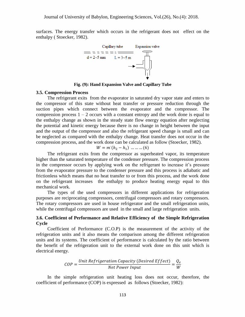
The capillary tube is used in the house’s refrigerators and in the small refrigeration
units, while the expansion valves are used in the large refrigeration units as shown in
figure (9). The capillary tubes are copper tubes with diameter d = 2 ~ 5 mm and length L
= 3 ~ 5 m. The refrigerant pressure reduction is due to hydraulic losses. When it flows
through these tubes the rough metal surface resists the liquid flow and reduce the
pressure. There are three types of expansion valves: hand expansion valve, automatic
expansion valve and the high quality and efficiency type which is thermostatic expansion
valve. The theory of hand expansion valve work depends on the refrigerant flow through
a nozzle produce throttling and pressure reduction with constant enthalpy. It is possible to
control the levels of high and low pressure and also the refrigerant flow rate by a metal
needle which is used to increase or decrease the hole area of the nozzle by the hand. In
expansion process with a constant enthalpy the refrigerant exits from expansion valve as
mixture of saturated liquid and saturated dry vapor at pressure and temperature of the
evaporator. The entropy change during the expansion process caused by heating energy
transfer in the refrigerant due to internal friction between refrigerant particles and metal
Journal of University of Babylon, Engineering Sciences, Vol.(26), No.(4): 2018.
113
surfaces. The energy transfer which occurs in the refrigerant does not effect on the
enthalpy ( Stoecker, 1982).
Fig. (9): Hand Expansion Valve and Capillary Tube
3.5. Compression Process
The refrigerant exits from the evaporator in saturated dry vapor state and enters to
the compressor of this state without heat transfer or pressure reduction through the
suction pipes which connect between the evaporator and the compressor. The
compression process 1 – 2 occurs with a constant entropy and the work done is equal to
the enthalpy change as shown in the steady state flow energy equation after neglecting
the potential and kinetic energy because there is no change in height between the input
and the output of the compressor and also the refrigerant speed change is small and can
be neglected as compared with the enthalpy change. Heat transfer does not occur in the
compression process, and the work done can be calculated as follow (Stoecker, 1982).
The refrigerant exits from the compressor as superheated vapor, its temperature
higher than the saturated temperature of the condenser pressure. The compression process
in the compressor occurs by applying work on the refrigerant to increase it’s pressure
from the evaporator pressure to the condenser pressure and this process is adiabatic and
frictionless which means that no heat transfer to or from this process, and the work done
on the refrigerant increases the enthalpy to produce heating energy equal to this
mechanical work.
The types of the used compressors in different applications for refrigeration
purposes are reciprocating compressors, centrifugal compressors and rotary compressors.
The rotary compressors are used in house refrigerator and the small refrigeration units,
while the centrifugal compressors are used in the small and large refrigeration units.
3.6. Coefficient of Performance and Relative Efficiency of the Simple Refrigeration
Cycle
Coefficient of Performance (C.O.P) is the measurement of the activity of the
refrigeration units and it also means the comparison among the different refrigeration
units and its systems. The coefficient of performance is calculated by the ratio between
the benefit of the refrigeration unit to the external work done on this unit which is
electrical energy.
In the simple refrigeration unit heating loss does not occur, therefore, the
coefficient of performance (COP) is expressed as follows (Stoecker, 1982):

Journal of University of Babylon, Engineering Sciences, Vol.(26), No.(4): 2018.
114
The relative efficiency ηR of the refrigeration unit is the ratio between the
coefficient of performance of the simple refrigeration cycle to the coefficient of
performance of the Carnot cycle which operates at the same conditions of pressures and
temperatures:
From the previous explanation of the simple vapor compression refrigeration cycle
we note that the condenser job through process 2 – 3 is to reject the heat gain of the
refrigerant to the surround continuously without benefit from it. To implement the
objective of this research which is manufacturing and using the refrigerator as heat pump
of recover heat, the following parts have been added to the refrigeration system which is
represent the simple vapor compression refrigeration cycle.
4. Heating Cabinet Heating cabinet has been designed with the following internal dimensions (heating
space): width 52 cm, height 20 cm and depth 48 cm, while the external dimensions are
width 64 cm, height 32 cm and depth 60 cm. Heating recovery coil has been put inside
the heating space of the cabinet which is small coil and has the same pipes diameters
and metal of the refrigerator condenser ( diameter 4 mm and length 200 cm). The total
area of this coil represents 40 % of the total area of the original refrigerator condenser
which is the required area to remove the super heat from the superheated vapor of the
refrigerant and convert it to saturated liquid. The cabinet structure is thermally insulated
by using a glass wool (thermal insulator) with thickness of 3 cm to obtain good insulation
(ASHRAE, 1983). Thermal interaction occurs between the super heated vapor and the
cabinet air which surrounds the foods by using a small fan which has been connected
(constructed) inside the cabinet to increase the activity of the supper heat drawing and
benefit from it in food heating as shown in figure (10).
Fig. (10): Heating Cabinet

Journal of University of Babylon, Engineering Sciences, Vol.(26), No.(4): 2018.
115
5. By – Bass Line Joint of T form has been added and mounted directly on the discharge line of the
compressor and mounted on it the required valves to reverse the super heated vapor flow
which exits from the compressor in the direction of the reheating coil of the cabinet
instead of it’s moving in the direction of the condenser.
6. Solenoid Valves (Magnetic Valves) Three magnetic valves have been added to this system, two of which operate at the
same time special for the cabinet operation, and the third valve is special for the
refrigerator operation in state of operating it without the cabinet and connected directly
by the condenser. The operation of the third valve is opposite to the first and second
valves as shown in the figure (11).
Fig. (11): By – Pass Line and Solenoid Valves
7. The Electrical and Examination Circuit of Refrigerator with Heat Recovery
System
As it is known the electrical circuit of the refrigerator consists of the electrical
motor coils of the compressor which are represented by the running or (operation) coils
and the starting coils. The circuit contains also an over load , a relay and a control unit of
the required temperature (Thermostat control), as well as groups of electrical wires. The
electrical circuit is modified to become more suitable with the object of this study. A
special electrical circuit has been implemented in state of using the magnetic valves
(solenoid valves) as shown in figure (12). Electrical switch has been added to provide the
electrical current to the magnetic valves. The cabinet fan is operated to reheat the foods.
The electrical circuit is operated as a heat pump or as a simple refrigeration cycle.

Journal of University of Babylon, Engineering Sciences, Vol.(26), No.(4): 2018.
116
Fig. (12) Electrical Circuit of Refrigerator with Heat Recovery Coil
The examination circuit has been designed to implement the objective of this
research. Group of pressure and temperature gauges have been added to measure the
pressure and temperature of the refrigerant and air inside the heating and cooling cabinets
and their details and locations are explained in figure (13). The mechanical circuit is
constructed by using the welding joints and the pipes lines joints. Finally the refrigerator
is charged by the refrigerant R134a with magnitude of 90 g.
Capillary tubeFilter DrierSide Glass
Compressor
Hea
t E
xch
an
ger
Co
nd
en
ser
Ev
ap
ora
tor
Discharge Line
Suction LIne
Solenoid Valve 1
Solenoid Valve 2
Solenoid Valve 3
Discharge
Pressure Gage
Condenser Exit
Pressure Gage
Cabinet Pressure
Gage
Suction
Pressure Gage
T2
T1
T6
T8
T3
T7
T4
T5
Evaporator
Input Pressure
Gage
Heat recovery
coil
Fig. (13:) Mechanical Circuit of Refrigerator with Heat Recovery Coil
8. Results Discussion Several experiments have been implemented on the manufactured refrigerator in
order to explain the effect of the addition of the heat recovery coil on the coefficient of

Journal of University of Babylon, Engineering Sciences, Vol.(26), No.(4): 2018.
117
performance (C.O.P.). The refrigerator has been operated without the heat recovery coil
continuously for one hour, and the readings have been recorded every 10 minutes without
stopping in the compressor operation to show the refrigerator performance during the
long operation (Ali, 2011). The readings of the examination refrigerator have been
recorded in the laboratory with normal thermal conditions ( temperature is 25 ~ 27 C˚ and
good ventilation state), and then the refrigerator has been operated at the same thermal
conditions with the heat recovery coil and these readings are showed in tables (1) and (2).
Table (1): Refrigerator Operation Only
Time
min
Pressure (Bar) Temperature (C˚)
Ga
ug
e 1
Ga
ug
e 2
Ga
ug
e 3
Ga
ug
e 4
Ga
ug
e 5
Su
ctio
n L
ine
T1
Dis
cha
rge
Lin
e T
2 Co
nd
ense
r
Inp
ut
T6
Co
nd
ense
r
Ex
it T
3 Eva
po
rato
r
Inp
ut
T4
Eva
po
rato
r
Ex
it T
5 Eva
po
rato
r
Su
rfa
ce T
7
Co
oli
ng
Ca
bin
et
10 12.3 - 12 0.9 0.4 18 59 51 44 -4 11 -9 28
20 12.3 - 12 0.9 0.4 16 66 56 45 -6 5 -17 21
30 12.2 - 12 0.8 0.4 14.5 71 59 46 -9 3 -19 17
40 12.2 - 12 0.8 0.3 13 76 62 46 -10 2 -20 15
50 12.2 - 12 0.8 0.3 12 80 65 47 -11 1 -20 12
60 12.2 - 12 0.7 0.3 12 84 67 48 -11 1 -21 10
Table(2): Refrigerator Operation with Heat Recovery Cabinet
Tim
e min
Pressure (Bar) Temperature (C˚)
Ga
ug
e 1
Ga
ug
e 2
Ga
ug
e 3
Ga
ug
e 4
Ga
ug
e 5
Su
ctio
n L
ine
T1
Dis
cha
rge
Lin
e T
2 C
on
den
ser
Inp
ut
T6
Co
nd
ense
r
Ex
it T
3 Eva
po
rato
r
Inp
ut
T4
Eva
po
rato
r
Ex
it
T5
Eva
po
rato
r
Su
rfa
ce T
7
Co
oli
ng
Ca
bin
et H
eati
ng
Ca
bin
et T
8
Hea
tin
g
Ca
bin
et
10 10 10 9.8 0.8 0.3 17 57 47 39 -9 8 -9 28 49 40
20 10.5 10.4 10.3 0.8 0.3 15 64 48.
5 41 -11 4 -18 21 56 46
30 11 10.9 10.7 0.8 0.4 13.5 70 49.
5 42 -12.5 2 -20 15 62 50
40 11.3 11.1 11 0.9 0.4 11 74 50 43 -13 1 -21 13 66 53
50 11.5 11.3 11.2 0.9 0.4 10 77 50.
5 43.
5 -12.5 -0.5 -22 11 70 56
60 11.7 11.3 11.2 0.9 0.4 9.5 80 51 44 -13 -1 -22.5 9.5 74 59.5
The essential factors (parameters) of the research can be discussed from the above
practicable readings as follow:

Journal of University of Babylon, Engineering Sciences, Vol.(26), No.(4): 2018.
118
8.1. Refrigerant Temperature
It can be noted that the refrigerant temperature which leaves the condenser T3 when
the refrigerator is operated as the refrigeration cycle with the heat recovery system is
reduced by the value of 4 C˚ to 6 C˚ less than their values in the refrigerator operation
state as the refrigeration cycle only. This means that when the refrigerant flow has been
reversed in direction of the heat recovery coil led to increase the value of the refrigerant
cooling (sub cooling liquid) in the condenser and before enters to the heat exchanger
which consists of the capillary tube of the liquid line and the suction line of the
compressor. This increasing in the refrigeration is rather high in the houses refrigerators
which depend on the natural air refrigeration (cooling) (Roy, 2002; Hand Book of
Refrigeration,1977). This leads to increase the amount of the absorbed heat in the
evaporator coil which increases the refrigeration effect of the cycle as shown in the
figure (14).
Fig. (14): Outlet Condenser Temperature for Simple Vapor Compression Refrigeration
Cycle With or Without Heat Recovery Coil
8.2. Heat Recovery Cabinet
From table (2) can be noted that the air temperature inside the reheating cabinet is
approximately not less than 40 C˚ after 10 minutes of operation to reach 60 C˚ after one
hour of operation with the increasing rate approximately reach to 4 C˚ every 10 minutes
of operation.
This temperature can be increased with the continuous operation over one hour or
at increasing the degree of vapor super heat which is incoming from the compressor
during the operation of the refrigeration cycle, as well as , that the air circulation inside
the heating cabinet by using the fan will make the temperature inside the cabinet always
high, and then the benefit ability from it in food reheating or saving it in hot state at less
(ASHRAE, 1981).
8.3. Super heat Removing Zone
The refrigeration cycle and (P – H) diagram of the refrigerator with or without the
reheat cabinet are explained in figures (15) and (16) which explain that when the

Journal of University of Babylon, Engineering Sciences, Vol.(26), No.(4): 2018.
119
additional valves are used in the cycle, the heat recovery process or superheat removing
process will be limited between point 6 and 8, and which in assumption is removed heat
out the condenser in state of operation the refrigerator only, but benefit from it to heating
the foods in the heat recovery coil.
Heat Exchanger
Evaporator
Condenser
Expansion Valve
Compressor
1
2
4
3
5
6
3'
T5
T2
T1
T3T6
T3'
T4
Fig. (15): Simple Vapor Compression Refrigeration Cycle Only

Journal of University of Babylon, Engineering Sciences, Vol.(26), No.(4): 2018.
120
Heat Exchanger
Evaporator
Condenser
Cabinet Heat
Exchanger
Valve 1Valve 3
Valve 2
Expansion Valve
Compressor
Ref
rige
rati
on
Ope
rati
on O
nly
Ref
rige
rati
on O
pera
tion
wit
h C
abin
et
1
2
4
3
5
6 8
3'
T5
T2
T1
T3T8T6
T3'
T4
Fig. (16) : Simple Vapor Compression Refrigeration Cycle With Heat Recovery Coil
8.4. Coefficient of Performance (C.O.P.)
The coefficient of performance is calculated in both operation conditions from the
equation (7) which depends on the enthalpy change of the refrigerant and is found from
(P – H) diagram of the refrigerant R134a. All values of the coefficient of performance of
the readings for both operation state have been inserted in figure (17), and note that there
is an improve in the coefficient of performance when the refrigerant flow is reversed in
the direction of the heat recovery cabinet with a percentage reach to 20 % more than it’s
values when the refrigerator is operated only.

Journal of University of Babylon, Engineering Sciences, Vol.(26), No.(4): 2018.
121
Fig. (17): Coefficient of performance of the refrigerator with or with out cabinet
8.5. Pressure Reduction
The value of the refrigerant pressure reduction due to the addition of the magnetic
values and the heat recovery coil has been calculated. Generally the rates of pressure
difference between both state of operation are small and can be neglected because the
pipe diameter of the heat recovery coil is the same pipe diameter of the condenser, and
due to small distance between valves location or between the heat recovery coil and the
main parts of the refrigeration cycle , thus the addition lengths are small. Then the rates
of pressure reduction are constant and suitable with the designed rates of the
refrigeration cycle in the refrigerators industry (Althouse, 1988 ; Wang, 2001).
8.6. The Energy Consumption
The intensity of the electrical current and the voltage are calculated during the
operation of the refrigerator only or with the heat recovery cabinet by using ammeter and
voltmeter, then the consumed power can be calculated from the following equation
(William, 1995).
Where : P is the consumed electrical power (W), I is the drawn electrical current
(Amper) and V is the drawn voltage (volt). It can be shown from table (3) that the
electrical power is approximately constant in the both state of operation and the
difference does not exceed 25 W and this value is the fan and the magnetic valves
consumption which are very small in comparison with the refrigerator consumption.
Table (3): The Energy Consumption
Time
(min)
Frequency
(Hz)
Voltage
(volt)
Refrigerator Only
Refrigerator With
Heat Recovery
Cabinet
Current
(A)
Power
(W)
Current
(A)
Power
(W)
10 50 220 0.889 195.58 0.891 196.02
20 50 220 0.881 193.82 0.886 194.92
30 50 220 0.879 193.38 0.882 194.04
40 50 220 0.878 193.16 0.880 193.60
50 50 220 0.878 193.16 0.880 193.60
60 50 220 0.878 193.16 0.880 193.60

Journal of University of Babylon, Engineering Sciences, Vol.(26), No.(4): 2018.
122
8.7. The Initial and Operation Cost
When you are doing any change or modification in the refrigeration cycles, you
should be aware of effect of this development on the economical cost. In general, the cost
is divided into initial cost and operation cost. The initial cost represents the apparatus
manufacturing or buy it which is different according to the company of the manufacture,
manufacture properties and the refrigerator capacity (ASHRAE, 1999). Thus the idea of
refrigerator manufacture has three functions which are freezing, cooling and reheating
process in the heat recovery cabinet in stead of two functions (freezing and cooling only)
does not mean in necessary rise the initial cost due to the difference between the adopted
methods of manufacture in the companies , as well as, to the several variables such as
impost and prices change in markets.
The operation cost is represented by the cost of the electrical energy consumption
which is provided to the operation, and finally maintenance cost. This study explains
that no difference approximately between the consumed electrical power in the both
states of operation and the limited time for the cabinet operation or part of this time
occurs at the same time of the refrigeration cycle operation, this means in the same period
of the compressor work (operation), the process of heat recovery in the cabinet occurs in
the same period. Thus the increase in the consumed energy cost is not taken in to
consideration.
The maintenance cost is represented by repair costs or exchange damage parts . The
suggested additions on the refrigerator such as fan and valves are simple additions and
not complex thus do not need to the high maintenance cost, as example the fan motor can
be replaced immediately after it’s failure or doing the maintenance with out stopping the
operation of the refrigerator, and this case is similar to the valves (Automatic, 1997).
9. Conclusions From this study which is refrigerator manufacture with heat recovery system and
the obtained results, we can conclude the following points:
1. The benefit ability from the rejected heat of the compression refrigeration cycle of the
refrigerator by super heat recovery to reheat the foods or saving it hot at least, and also
the refrigerator operation as heat pump at the same time.
2. The coefficient of performance can be improved when the refrigerator is operated with
heat recovery system (heating cabinet).
3. The use of magnetic valves (solenoid valves) does not effect on the coefficient of
performance of the refrigeration cycle and the obtained results show that there is an
improvement in the coefficient of performance of the refrigeration cycle in state of the
cabinet operation with magnetic valves.
4. Generally the pressure reduction is small and approximately not considerable and then
does not effect on the performance of the refrigeration cycle of manufactured
refrigerator.
5. All the suggested additions are part of the operation cost which are the fan
maintenance and the magnetic valves. The consumed electrical energy to operate these
additions is small thus it can be manufacture a refrigerator has three functions which
are freezing, cooling and heating at the same time.

Journal of University of Babylon, Engineering Sciences, Vol.(26), No.(4): 2018.
123
References
“ASHRAE Hand Book of Equipment”,1983 , Chapter 38, American Society of
Heating, Refrigeration and Air Conditioning Engineering, Page 4 – 6.
“ASHRAE Hand Book of Equipment”,1985, Chapter 20, American Society of Heating,
Refrigeration and Air Conditioning Engineering, Page 21 – 28.
“ASHRAE Hand Book of Fundamentals”,1981, Chapter 31, American Society of
Heating, Refrigeration and Air Conditioning Engineering, Page 1 – 9.
“ASHRAE Handbook of Applications”,1999 ,American society of Heating,
Refrigeration and air-conditioning engineering, chapter 35.
“Hand Book of Refrigeration”,1977, Chapter 8, Trane Air Conditioning Company,
page 35 – 37.
Ali abdul Whaab Ismiael,2011, “Applied Study to Demonstrate the Potential of the
Work of the Refrigerator to Work as a Heat Recovery Device”, Engineering and
Technology Journal , October.
Althouse ,1988, “Modern Refrigeration and Air Conditioning”, Chapter 5, Page 141 –
159.
Automatic Controls for Refrigeration plant and Air conditioning systems Danfoss. Catalogue RK.00.H5.02, 1997.
Michael Yogesh, May 2008, “Heat Recovery from Vapor Compression air
Conditioning”.
Roy. J. Dossat ,2002, “Principles of Refrigeration”, Chapter 11, Part 3, Page 134 – 139.
SADC, 2006, Energy Efficiency Guide for Industry in Asia.
SADC. Energy Sector Module 15. Heat Recovery Systems, 1999 , “Heat Pump
Arrangement”, Industrial Energy Management Project for Candia.
Stoecker W. F. ,1982, “Refrigeration and Air Conditioning”, Chapter 10, Page 195 –
204.
Stoecker W. F. ,1982, “Refrigeration and Air Conditioning”, Chapter 12, Page 233 –
259.
Stoecker W. F. , 1982,“Refrigeration and Air Conditioning”, Chapter 13, Page 260 –
280.
Thomas H. Durkin, P.E, 2003, “Dedicated Heat Recovery Chiller”, ASHRAE Journal,
October.
Wang R. Z. , July, 2001, “performance Improvement of Adsorption Cooling by Heat and
Mass Recovery Operation”, International Journal of Refrigeration, Volume 24,
Issue 7.
William. C. Whitman , 1995, “Refrigeration & Air conditioning Technology”.
Yuns A. Cengel , 2006, “Thermodynamic an Engineering Approach”, Chapter 12, Page
651 – 680.
Yuns A. Cengel , 2006, “Thermodynamic an Engineering Approach”, Chapter 11, Page
610 – 614.
Related Documents