User Manual Indoor: MSS-8/MSS-4 + Outdoor: ODU300 / MPT-HC / MPT- HC V2 / MPT-MC 9500 MPR 3DB18809AAAA Issue 1 Rel. 3.1 May 2011 Downloaded from www.Manualslib.com manuals search engine

Welcome message from author
This document is posted to help you gain knowledge. Please leave a comment to let me know what you think about it! Share it to your friends and learn new things together.
Transcript

User Manual
Indoor: MSS-8/MSS-4 + Outdoor: ODU300 / MPT-HC / MPT-HC V2 / MPT-MC
9500 MPR
3DB18809AAAAIssue 1
Rel. 3.1
May 2011
Downloaded from www.Manualslib.com manuals search engine

Status: RELEASED
All rights reserved.Passing on and copying of this document,
use and communication of its contents is not permittedwithout written authorization from Alcatel-Lucent.
3DB18809AAAA Issue 1
Alcatel, Lucent, Alcatel-Lucent and the Alcatel-Lucent logo are trademarks of Alcatel-Lucent.
All other trademarks are the property of their respective owners.
The information presented is subject to change without notice. Alcatel-Lucent assumes no responsibility for inaccuracies contained herein.
Copyright © 2011 Alcatel-Lucent
Downloaded from www.Manualslib.com manuals search engine

User Manual
Table of Contents
9500 MPR Rel. 3.1
3DB18809AAAA Issue 1 1/980
TABLE OF CONTENTS
LIST OF FIGURES ......................................................................................................................... 7
LIST OF TABLES ........................................................................................................................... 21
PREFACE......................................................................................................................................... 23Preliminary Information.............................................................................................................. 23Applicability................................................................................................................................. 24Scope ........................................................................................................................................... 24History.......................................................................................................................................... 24Change notes .............................................................................................................................. 25Handbook Structure ................................................................................................................... 25General on Alcatel-Lucent Customer Documentation ............................................................ 26
1 SAFETY, EMC, EMF, ESD NORMS AND EQUIPMENT LABELLING ........................................ 311.1 Declaration of conformity to CE marking and Countries List ......................................... 321.2 Specific label for MPR-E equipment .................................................................................. 331.3 Applicable standards and recommendations ................................................................... 341.4 Safety Rules ......................................................................................................................... 34
1.4.1 General Rules................................................................................................................. 341.4.2 Labels Indicating Danger, Forbiddance, Command........................................................ 35
1.5 Electromagnetic Compatibility (EMC norms).................................................................... 391.6 Equipment protection against electrostatic discharges .................................................. 401.7 Cautions to avoid equipment damage ............................................................................... 40
2 PRODUCT INFORMATION AND PLANNING ............................................................................. 412.1 Purpose and Function......................................................................................................... 44
2.1.1 Innovative solutions ........................................................................................................ 442.1.2 Description...................................................................................................................... 472.1.3 MSS Purpose, Function and Description........................................................................ 482.1.4 Stacking configuration..................................................................................................... 512.1.5 ODU300.......................................................................................................................... 532.1.6 MPT-HC .......................................................................................................................... 542.1.7 MPT-MC.......................................................................................................................... 552.1.8 MPT-HC V2..................................................................................................................... 562.1.9 Power Extractor .............................................................................................................. 572.1.10 MSS to Outdoor Unit interconnections.......................................................................... 582.1.11 Antennas....................................................................................................................... 73
2.2 Radio capacity, channelling and modulation .................................................................... 742.2.1 ODU300.......................................................................................................................... 742.2.2 MPT-HC/MPT-HC V2/MPT-MC....................................................................................... 76
2.3 Standard Features ............................................................................................................... 802.4 Radio Configurations .......................................................................................................... 812.5 Typical System Configurations .......................................................................................... 812.6 Environmental and Electrical Characteristics................................................................... 85
2.6.1 System Parameters ........................................................................................................ 852.6.2 ODU300.......................................................................................................................... 872.6.3 MPT-HC/MPT-HC V2 ...................................................................................................... 882.6.4 MPT-MC.......................................................................................................................... 892.6.5 Radio performances ....................................................................................................... 902.6.6 General characteristics (Power Injector)......................................................................... 902.6.7 General characteristics (Power Extractor) ...................................................................... 91
2.7 Parts Lists............................................................................................................................. 922.7.1 Indoor items .................................................................................................................... 92
Downloaded from www.Manualslib.com manuals search engine

User Manual
Table of Contents
9500 MPR Rel. 3.1
3DB18809AAAA Issue 12/980
2.7.2 ODU300 (with internal lightning surge suppressor) ........................................................ 962.7.3 MPT-HC with internal diplexer ........................................................................................ 1102.7.4 MPT-HC V2 with internal diplexer ................................................................................... 1122.7.5 MPT-MC with internal diplexer ........................................................................................ 1142.7.6 Part lists of MPT-HC/MPT-HC V2/MPT-MC with external diplexer ................................. 1162.7.7 MPT-HC optical interface (mandatory for 1+1 configuration).......................................... 1192.7.8 MPT-HC V2 external modules (option) ........................................................................... 1202.7.9 MPT-HC/MPT-HC V2/MPT-MC couplers ........................................................................ 120
2.8 Functional description ........................................................................................................ 1212.8.1 MSS (Indoor Unit) ........................................................................................................... 1212.8.2 Power Extractor .............................................................................................................. 1362.8.3 Power Injector................................................................................................................. 1362.8.4 ODU300.......................................................................................................................... 1382.8.5 MPT-HC .......................................................................................................................... 1422.8.6 MPT-HC V2..................................................................................................................... 1502.8.7 MPT-MC.......................................................................................................................... 1512.8.8 Protection schemes ........................................................................................................ 1532.8.9 Stacking for EAS unit/MPT Access unit .......................................................................... 1602.8.10 Ethernet Ring Protection............................................................................................... 1602.8.11 Radio Transmission Features with ODU300................................................................. 1642.8.12 Radio Transmission Features with MPT-HC/MPT-HC V2/MPT-MC.............................. 1682.8.13 TMN interfaces ............................................................................................................. 1712.8.14 Admission control in Adaptive Modulation (only with ODU300).................................... 1712.8.15 Managed Services and profiles .................................................................................... 1762.8.16 TDM and Ethernet traffic management......................................................................... 1782.8.17 ATM Traffic Management.............................................................................................. 1832.8.18 Ethernet Traffic Management ....................................................................................... 1902.8.19 LAG (Link Aggregation Group) ..................................................................................... 1922.8.20 Quality Of Services (QoS) ............................................................................................ 1942.8.21 Cross-connections ........................................................................................................ 1992.8.22 Synchronization for PDH/SDH/DATA............................................................................ 2112.8.23 Synchronization for E1 ports with ASAP unit ................................................................ 2182.8.24 Synchronization distribution from 9500 MPR to 9400 AWY.......................................... 2182.8.25 Synchronization connection in Stacking configuration with Core protection ................. 219
3 NE MANAGEMENT BY SOFTWARE APPLICATION................................................................. 2213.1 WebEML start ....................................................................................................................... 2213.2 WebEML Main View ............................................................................................................. 223
3.2.1 Tab-panels ...................................................................................................................... 2243.2.2 Main Tool Bar Area ......................................................................................................... 2263.2.3 Severity Alarm Area........................................................................................................ 2273.2.4 Domain Alarm Synthesis Area........................................................................................ 2283.2.5 Management State Control Area .................................................................................... 2283.2.6 Selection Criteria ............................................................................................................ 229
3.3 How to configure a new equipment ................................................................................... 2303.4 Menu Configuration ............................................................................................................. 231
3.4.1 Menu NE Time ................................................................................................................ 2313.4.2 Menu Network Configuration .......................................................................................... 2323.4.3 Menu Alarm Severities.................................................................................................... 2383.4.4 Menu System Settings.................................................................................................... 2403.4.5 Menu Cross connections ................................................................................................ 2433.4.6 AUX Cross Connections ................................................................................................. 2943.4.7 Menu XPIC Configuration ............................................................................................... 2973.4.8 Menu VLAN Configuration .............................................................................................. 297
Downloaded from www.Manualslib.com manuals search engine
User Manual
Table of Contents
9500 MPR Rel. 3.1
3DB18809AAAA Issue 1 3/980
3.4.9 Traffic Descriptors........................................................................................................... 2973.4.10 Menu Profile Management............................................................................................ 2993.4.11 Ethernet Features Shell ................................................................................................ 305
3.5 Menu Diagnosis ................................................................................................................... 3413.5.1 Alarms............................................................................................................................. 3413.5.2 Log Browsing .................................................................................................................. 3483.5.3 Remote Inventory ........................................................................................................... 3513.5.4 Abnormal Condition List.................................................................................................. 3523.5.5 Summary Block Diagram View ....................................................................................... 3533.5.6 Current Configuration View............................................................................................. 370
3.6 Menu Supervision................................................................................................................ 3713.6.1 Access State ................................................................................................................... 3713.6.2 Restart NE ...................................................................................................................... 3723.6.3 Restart MPT.................................................................................................................... 3723.6.4 MIB Management ........................................................................................................... 3733.6.5 SW Licence..................................................................................................................... 375
3.7 Menu SW Download............................................................................................................. 3763.7.1 Server Access Configuration .......................................................................................... 3763.7.2 Init Sw Download ............................................................................................................ 3773.7.3 Sw Status........................................................................................................................ 3783.7.4 How to upgrade the software from an older version ....................................................... 379
3.8 Tab-panel Equipment........................................................................................................... 3803.8.1 General ........................................................................................................................... 3803.8.2 Starting From Scratch ..................................................................................................... 3833.8.3 Tab panels in the Resource Detail Area.......................................................................... 3843.8.4 Alarms tab-panel............................................................................................................. 3843.8.5 Settings tab-panel ........................................................................................................... 3853.8.6 Remote Inventory tab-panel............................................................................................ 3923.8.7 How to configure a new equipment ................................................................................ 392
3.9 Tab-panel Protection Schemes........................................................................................... 3933.9.1 Equipment Protection Management ............................................................................... 3983.9.2 Rx Radio Protection Management .................................................................................. 4013.9.3 HSB Protection Management ......................................................................................... 403
3.10 Tab-panel Synchronization ............................................................................................... 4053.10.1 Synchronization Sources assignment........................................................................... 4063.10.2 Synchronization sources assignment rules .................................................................. 4073.10.3 Allowed synchronization sources assignment .............................................................. 4073.10.4 SSM Summary Table .................................................................................................... 408
3.11 Tab-panel Connections...................................................................................................... 4093.12 PDH VIEW for PDH DOMAIN (this menu opens with double click on a PDH unit)....... 410
3.12.1 General information on the PDH domain menu............................................................ 4103.12.2 Alarms & Settings ......................................................................................................... 4103.12.3 Loopback ...................................................................................................................... 416
3.13 SDH VIEW for SDH DOMAIN (this menu opens with double click on an SDH unit) .... 4183.13.1 General information on the SDH unit ............................................................................ 4183.13.2 Alarms........................................................................................................................... 4193.13.3 Settings for SDHACC unit (Transparent mode) ............................................................ 4193.13.4 Settings for SDHCHAN unit (Channelized mode)......................................................... 420
3.14 EAS VIEW for EAS DOMAIN.............................................................................................. 4243.14.1 EAS Domain ................................................................................................................. 424
3.15 Ethernet Ring Configuration View.................................................................................... 4283.15.1 ERP Configuration ........................................................................................................ 4283.15.2 ERP Configuration procedure....................................................................................... 4343.15.3 Configuration example of an Ethernet ring ................................................................... 440
Downloaded from www.Manualslib.com manuals search engine
User Manual
Table of Contents
9500 MPR Rel. 3.1
3DB18809AAAA Issue 14/980
3.16 XPIC configuration............................................................................................................. 4413.16.1 1+0 XPIC ...................................................................................................................... 4423.16.2 1+1 XPIC ...................................................................................................................... 4443.16.3 How to remove the XPIC association ........................................................................... 444
3.17 RADIO VIEW for RADIO DOMAIN ..................................................................................... 4453.17.1 General information on the Radio domain menu .......................................................... 4453.17.2 Alarms........................................................................................................................... 4463.17.3 Settings......................................................................................................................... 4463.17.4 Measurement................................................................................................................ 4693.17.5 Loopback ...................................................................................................................... 4713.17.6 Power Source ............................................................................................................... 474
3.18 ATM view for ATM DOMAIN (this menu opens with double click on an ASAP unit).... 4763.18.1 E1 Layer ....................................................................................................................... 4763.18.2 IMA Layer ..................................................................................................................... 4773.18.3 ATM Layer..................................................................................................................... 4793.18.4 ATM PW Layer.............................................................................................................. 485
3.19 Core-E VIEW for Core-E and ETHERNET DOMAIN (this menu opens with double click on a Core-E unit) .............................................................................................................................. 487
3.19.1 Core-E domain.............................................................................................................. 4873.20 AUX view for AUX DOMAIN (this menu opens with double click on the AUX peripheral unit)498
3.20.1 Settings......................................................................................................................... 4983.20.2 External Points.............................................................................................................. 499
3.21 WT Performance Monitoring Suite ................................................................................... 5013.21.1 How to start the WT Performance Monitoring Suite...................................................... 5013.21.2 Tool bar ......................................................................................................................... 5023.21.3 Menu bar....................................................................................................................... 5043.21.4 Feature bar area ........................................................................................................... 5063.21.5 PM counter view area ................................................................................................... 5063.21.6 How to start and stop the PM ....................................................................................... 5073.21.7 PM selectable options................................................................................................... 5113.21.8 Ethernet Statistics ......................................................................................................... 5123.21.9 RADIO PMs .................................................................................................................. 5233.21.10 Adaptive Modulation ................................................................................................... 5323.21.11 PDH Performance Monitoring ..................................................................................... 5353.21.12 IMA Layer Statistics .................................................................................................... 5413.21.13 ATM Interface Statistics .............................................................................................. 5443.21.14 RSL History................................................................................................................. 547
3.22 VLAN management ............................................................................................................ 5483.22.1 802.1D .......................................................................................................................... 5483.22.2 802.1Q .......................................................................................................................... 5493.22.3 Ethernet Ring................................................................................................................ 553
3.23 Annex A: Network Element Overview.............................................................................. 5543.23.1 Main view...................................................................................................................... 5543.23.2 NE Configuration area .................................................................................................. 5553.23.3 Status & Alarms area .................................................................................................... 5573.23.4 Supervision Function .................................................................................................... 5573.23.5 Menu bar....................................................................................................................... 5583.23.6 CS (Community String) ................................................................................................. 560
4 INSTALLATION............................................................................................................................ 5634.1 Hardware Installation........................................................................................................... 563
4.1.1 Power consumption ........................................................................................................ 5644.1.2 Rack Installation ............................................................................................................. 565
Downloaded from www.Manualslib.com manuals search engine

User Manual
Table of Contents
9500 MPR Rel. 3.1
3DB18809AAAA Issue 1 5/980
4.1.3 MSS Indoor Installation................................................................................................... 5804.1.4 Power Injector Indoor Installation.................................................................................... 6304.1.5 ODU300 Installation........................................................................................................ 6324.1.6 MPT-HC Installation ........................................................................................................ 6534.1.7 MPT-HC V2 Installation................................................................................................... 7144.1.8 MPT-MC Installation........................................................................................................ 7294.1.9 Power Extractor .............................................................................................................. 7654.1.10 Nose Adapter for MPT-HC/V2 and MPT-MC ................................................................ 7664.1.11 Flextwists for MPT-HC/V2 and MPT-MC....................................................................... 7664.1.12 Antenna Alignment ....................................................................................................... 767
4.2 Software local copy ............................................................................................................. 7784.2.1 Getting Started................................................................................................................ 7794.2.2 PC Characteristics .......................................................................................................... 7794.2.3 Local copy of the Software Package (SWP) to the PC................................................... 7804.2.4 Local copy of the WebEML and TCO Suite Software to PC ........................................... 7824.2.5 Configure PC Network Card to Connect to NE............................................................... 7904.2.6 Download Software Package to NE................................................................................ 794
5 PROVISIONING............................................................................................................................ 8015.1 Provisioning by Provisioning Tool..................................................................................... 801
5.1.1 Start Provisioning Tool .................................................................................................... 8015.2 Provisioning by WebEML.................................................................................................... 834
5.2.1 Start WebEML................................................................................................................. 8345.2.2 Provisioning .................................................................................................................... 837
6 MAINTENANCE AND TROUBLE-CLEARING ............................................................................ 8916.1 Introduction .......................................................................................................................... 8916.2 Maintenance Philosophy..................................................................................................... 8926.3 Personal Computer (PC)/Laptop ........................................................................................ 8926.4 Troubleshooting................................................................................................................... 892
6.4.1 Before Going to Site Checklist ........................................................................................ 8926.4.2 Troubleshooting Basics................................................................................................... 8936.4.3 Troubleshooting Path Problems...................................................................................... 9166.4.4 Troubleshooting Configuration Problems........................................................................ 9186.4.5 Troubleshooting Ethernet Problems ............................................................................... 9186.4.6 Troubleshooting TMN Problems ..................................................................................... 919
6.5 Card Removal and REPLACEMENT................................................................................... 9206.5.1 Core-E Card Removal and Replacement – Core-E Protected Radio ............................. 9226.5.2 Flash card replacement procedure ................................................................................. 9226.5.3 ODU300 or MPT-HC V2 or MPT-MC removal and replacement..................................... 9236.5.4 MPT-HC removal and replacement................................................................................. 923
6.6 Upgrade from Not Protected to a Protected Radio (with ODU300) ................................. 9246.6.1 1+0 Adaptive Modulation to 1+1 HSB Adaptive Modulation and 1+1 EPS..................... 9246.6.2 1+0 Static Modulation to 1+1 HSB Static Modulation and 1+1 EPS ............................... 9256.6.3 1+0 to 1+1 Frequency Diversity and 1+1 EPS................................................................ 925
6.7 Upgrade from Not Protected to a Protected Radio (with MPT-HC/MPT-HC V2 or MPT-MC)926
6.7.1 1+0 Adaptive Modulation to 1+1 HSB/FD Adaptive Modulation and 1+1 EPS............... 9266.7.2 1+0 Static Modulation to 1+1 HSB/FD Static Modulation and 1+1 EPS ......................... 927
6.8 Downgrade from Protected to a Not Protected Radio (with ODU300) ............................ 9286.8.1 1+1 HSB Adaptive Modulation and 1+1 EPS to 1+0 Adaptive Modulation..................... 9286.8.2 1+1 HSB Static Modulation and 1+1 EPS to 1+0 Static Modulation ............................... 9296.8.3 1+1 FD to 1+0................................................................................................................. 929
6.9 Downgrade from Protected to a Not Protected Radio (with MPT-HC/MPT-HC V2 or MPT-MC)931
Downloaded from www.Manualslib.com manuals search engine

User Manual
Table of Contents
9500 MPR Rel. 3.1
3DB18809AAAA Issue 16/980
6.9.1 1+1 HSB/FD Adaptive Modulation and 1+1 EPS to 1+0 Adaptive Modulation ............... 9316.9.2 1+1 HSB/FD Static Modulation and 1+1 EPS to 1+0 Static Modulation ......................... 932
6.10 Cleaning.............................................................................................................................. 932
7 LINE–UP AND COMMISSIONING ............................................................................................... 9337.1 Introduction .......................................................................................................................... 934
7.1.1 General ........................................................................................................................... 9347.1.2 Safety–EMC–EMF–ESD norms and cautions to avoid equipment damage................... 9357.1.3 Conventions.................................................................................................................... 9357.1.4 Summary of the line–up, commissioning, and acceptance phases ................................ 9367.1.5 General information about test bench drawings ............................................................. 937
7.2 Commissioning of STATION A – phase 1 (Turn up).......................................................... 9387.2.1 Turn–on preliminary operations ...................................................................................... 9387.2.2 Powering up the MSS(s) with ODU(s) connected........................................................... 939
7.3 Commissioning of STATION B – phase 1 (Turn up).......................................................... 9407.4 Fine antenna alignment and preliminary checks – Stations A & B................................. 940
7.4.1 Fine antenna alignment .................................................................................................. 9407.4.2 Preliminary checks.......................................................................................................... 940
7.5 End of commissioning phase 1 (Turn up) in STATION A ................................................. 9447.6 Commissioning station A – phase 2 (acceptance test) .................................................... 945
7.6.1 Installation and cabling visual inspection ........................................................................ 9477.6.2 System configuration ...................................................................................................... 9477.6.3 P32E1 unit ...................................................................................................................... 9527.6.4 STM-1 unit ...................................................................................................................... 9557.6.5 16E1/DS1 ASAP unit ...................................................................................................... 9587.6.6 AUX unit.......................................................................................................................... 9587.6.7 EAS unit .......................................................................................................................... 9597.6.8 Core-E unit...................................................................................................................... 9597.6.9 NE configuration ............................................................................................................. 9597.6.10 Data/Time settings ........................................................................................................ 9607.6.11 E1 Hop stability test ...................................................................................................... 9607.6.12 STM-1 Hop stability test................................................................................................ 9627.6.13 Ethernet Traffic stability test.......................................................................................... 9647.6.14 ATM Traffic stability test ................................................................................................ 9687.6.15 64 kbit/s Service Channel functionality test (optional) .................................................. 970
7.7 Commissioning station B – Phase 2 (acceptance Test) ................................................... 9717.8 Final operations ................................................................................................................... 9717.9 Annex A: fine antenna alignment ....................................................................................... 971
ABBREVIATIONS ............................................................................................................................ 973
CUSTOMER DOCUMENTATION FEEDBACK.............................................................................. 979
Downloaded from www.Manualslib.com manuals search engine

User Manual
List of Figures
9500 MPR Rel. 3.1
3DB18809AAAA Issue 1 7/980
LIST OF FIGURES
Figure 1. Multiservice Aggregation Layer ......................................................................................... 44Figure 2. Service Awareness ............................................................................................................ 45Figure 3. Packet Node ...................................................................................................................... 46Figure 4. Service-driven Packet Adaptive Modulation ...................................................................... 46Figure 5. Naming Convention ........................................................................................................... 47Figure 6. MSS-8 shelf ....................................................................................................................... 48Figure 7. MSS-4 shelf ....................................................................................................................... 48Figure 8. MSS-8 block diagram ........................................................................................................ 50Figure 9. MSS-4 block diagram ........................................................................................................ 50Figure 10. Stacking configuration with 3 MSS .................................................................................. 51Figure 11. Stacking configuration with 3 MSS with Core protection.................................................. 52Figure 12. ODU300........................................................................................................................... 53Figure 13. MPT-HC (11-38 GHz on the left side; 6 GHz on the right side) ....................................... 54Figure 14. MPT-MC........................................................................................................................... 55Figure 15. MPT-HC V2...................................................................................................................... 56Figure 16. Power Extractor ............................................................................................................... 57Figure 17. MSS to ODU300 interconnection..................................................................................... 58Figure 18. MSS to MPT-HC interconnection..................................................................................... 59Figure 19. MSS to MPT-HC interconnection..................................................................................... 60Figure 20. MSS to MPT-HC interconnection..................................................................................... 61Figure 21. MSS to MPT-HC interconnection..................................................................................... 62Figure 22. MPT-HC connection through the Power Injector Box ...................................................... 63Figure 23. MPT-HC connection through the Power Injector Plug-in installed in the MSS................ 64Figure 24. MSS to MPT-HC V2 interconnection ............................................................................... 65Figure 25. MSS to MPT-HC V2 interconnection ............................................................................... 66Figure 26. MSS to MPT-HC V2 interconnection ............................................................................... 67Figure 27. MPT-HC V2 connection through the Power Injector Box................................................. 68Figure 28. MPT-HC V2 connection through the Power Injector Plug-in installed in the MSS ........... 69Figure 29. MPT-HC/MPT-HC V2 directly connected to the battery ................................................... 70Figure 30. MSS to MPT-MC interconnection .................................................................................... 71Figure 31. MPT-MC connection through the Power Injector Box...................................................... 72Figure 32. MPT-MC connection through the Power Injector Plug-in installed in the MSS ................ 73Figure 33. PDH/ATM Over Ethernet Packet Node - Mapping of 32 E1 and �16 E1 ATM on Ethernet..................................................................................................................... 82Figure 34. PDH/SDH/ATM and Ethernet Terminal Packet Transport 32 E1, 2xSTM-1 and �16 E1 ATM Access, 1 Radio Direction .............................................................................................. 82Figure 35. PDH/SDH/ATM and Ethernet Add/Drop Packed Node-Ethernet and 32 E1, 2xSTM-1 and 16 E1 ATM Local Access, 1 Back Link, 1 Haul Link .............................................................................. 83Figure 36. PDH/SDH/ATM and Ethernet Terminal Packet Node-Ethernet and 32 E1, 2xSTM-1 and �16 E1 ATM Local Access, 2 Back Links............................................................................................ 83Figure 37. PDH/SDH/ATM and Ethernet Add/Drop Packet Node-Ethernet and 32 E1, 2xSTM-1 and �16 E1 ATM Local Access, 1 Back Link and 2 Haul Links.................................................................. 84Figure 38. PDH/SDH/ATM and Ethernet Add/Drop Packet Node-Ethernet and 32 E1, 2xSTM-1 and �16 E1 ATM Local Access, 2 Haul Links and 2 Back Links................................................................ 84Figure 39. Power Distribution Architecture ....................................................................................... 122Figure 40. +24 Vdc/-48 Vdc Converter unit....................................................................................... 123Figure 41. Core-E unit....................................................................................................................... 124Figure 42. Core-E unit....................................................................................................................... 126Figure 43. 32xE1 Local Access unit.................................................................................................. 126Figure 44. PDH Access unit.............................................................................................................. 127Figure 45. 2xSTM-1 Local Access unit ............................................................................................. 127Figure 46. STM-1 Access unit........................................................................................................... 128
Downloaded from www.Manualslib.com manuals search engine

User Manual
List of Figures
9500 MPR Rel. 3.1
3DB18809AAAA Issue 18/980
Figure 47. ASAP simplified block diagram........................................................................................ 130Figure 48. ASAP unit ........................................................................................................................ 131Figure 49. Modem unit ...................................................................................................................... 131Figure 50. Modem unit ...................................................................................................................... 132Figure 51. MPT Access unit (with PFoE) block diagram................................................................... 133Figure 52. MPT Access Unit (with PFoE) ......................................................................................... 134Figure 53. EAS unit block diagram ................................................................................................... 135Figure 54. EAS unit........................................................................................................................... 135Figure 55. Power Extractor ............................................................................................................... 136Figure 56. Power Injector plug-in ...................................................................................................... 137Figure 57. Power Injector box ........................................................................................................... 137Figure 58. Power Injector front panel................................................................................................ 137Figure 59. ODU300 housing ............................................................................................................. 138Figure 60. ODU block diagram ......................................................................................................... 139Figure 61. MPT system..................................................................................................................... 143Figure 62. 11-38 GHz MPT-HC housing ........................................................................................... 143Figure 63. 6 GHz MPT-HC housing .................................................................................................. 143Figure 64. 7-8 GHz MPT-HC housing ............................................................................................... 144Figure 65. MPT-HC block diagram.................................................................................................... 144Figure 66. 7/8 GHz MPT-HC architecture ......................................................................................... 147Figure 67. 11 to 38 GHz MPT-HC architecture ................................................................................. 148Figure 68. MPT-HC V2 housing (6 GHz and 11 GHz to 38 GHz) ..................................................... 150Figure 69. 6 GHz and from 11 to 38 GHz MPT-MC housing............................................................. 151Figure 70. 7-8 GHz MPT-MC housing............................................................................................... 151Figure 71. MPT-HC/MPT-HC V2 protection schemes....................................................................... 154Figure 72. MPT-MC protection schemes .......................................................................................... 156Figure 73. Normal Operation (No-fault) ............................................................................................ 161Figure 74. Single link failure.............................................................................................................. 162Figure 75. Multiple ERPS instances (Normal No-fault Operation) .................................................... 163Figure 76. Multiple ERPS instances (Single Link Failure) ................................................................ 163Figure 77. Single 2+0 XPIC .............................................................................................................. 165Figure 78. Double 1+1 HSB co-channel XPIC.................................................................................. 166Figure 79. Available loopbacks ......................................................................................................... 167Figure 80. Available loopbacks ......................................................................................................... 169Figure 81. Example of traffic in case of 28MHz bandwidth and Admission Control Enabled............ 172Figure 82. Example of traffic in case of 28MHz bandwidth and modulation downgraded to 16QAM 173Figure 83. Example of traffic in case of 28MHz bandwidth and modulation downgraded to 4QAM . 173Figure 84. Example of traffic in case of 28MHz bandwidth and Admission Control Disabled........... 174Figure 85. Example of traffic in case of 28MHz bandwidth and modulation downgraded to 16QAM 175Figure 86. Example of traffic in case of 28MHz bandwidth and modulation downgraded to 4QAM . 175Figure 87. Traffic profiles .................................................................................................................. 178Figure 88. Traffic profiles .................................................................................................................. 179Figure 89. E1 Traffic.......................................................................................................................... 180Figure 90. E1 Traffic.......................................................................................................................... 181Figure 91. STM-1 Traffic ................................................................................................................... 182Figure 92. E1 Traffic.......................................................................................................................... 182Figure 93. ATM Traffic Management - General block diagram ......................................................... 183Figure 94. Block diagram for ATM Ingress (ATM -> Packet) direction .............................................. 184Figure 95. ATM Traffic Management on Modem card - Block diagram............................................. 187Figure 96. Radio LAG overview ........................................................................................................ 192Figure 97. Radio LAG ....................................................................................................................... 193Figure 98. Ethernet LAG................................................................................................................... 193Figure 99. QoS in the Core-E unit..................................................................................................... 194Figure 100. QoS in the Modem unit .................................................................................................. 196
Downloaded from www.Manualslib.com manuals search engine

User Manual
List of Figures
9500 MPR Rel. 3.1
3DB18809AAAA Issue 1 9/980
Figure 101. Cross-connection........................................................................................................... 199Figure 102. Synchronization distribution from MPR to AWY............................................................. 218Figure 103. Synchronization connection in Stacking configuration with Core protection.................. 219Figure 104. MSS-8 Main view........................................................................................................... 223Figure 105. MSS-4 Main view........................................................................................................... 224Figure 106. Alarm Severities Profile ................................................................................................. 238Figure 107. System Settings menu................................................................................................... 240Figure 108. Main Cross-Connections View....................................................................................... 244Figure 109. Cross-connections Example .......................................................................................... 246Figure 110. Creating cross-connection between PDH and radio ...................................................... 247Figure 111. Cross-connections buttons............................................................................................. 247Figure 112. Segregated Port View (default configuration) ................................................................ 248Figure 113. ....................................................................................................................................... 248Figure 114. ....................................................................................................................................... 249Figure 115. Segregated Ports ........................................................................................................... 249Figure 116. Actual coloured view example ....................................................................................... 251Figure 117. PDH to Radio configuration dialog................................................................................. 253Figure 118. Completed PDH to Radio cross-connection .................................................................. 254Figure 119. Radio to Radio configuration dialog ............................................................................... 254Figure 120. Completed Radio to Radio cross-connection ................................................................ 255Figure 121. Radio/MPT-ACC to Ethernet configuration dialog (ranges) ........................................... 256Figure 122. Radio/MPT-ACC to Ethernet configuration dialog (values)............................................ 256Figure 123. Completed Radio/MPT-ACC to Ethernet cross-connection ........................................... 257Figure 124. PDH to Ethernet configuration dialog ............................................................................ 257Figure 125. Completed PDH to Ethernet cross-connection .............................................................. 258Figure 126. No protection ................................................................................................................. 258Figure 127. 1+1 radio protection between NE B and C .................................................................... 259Figure 128. 1+1 EPS protection in NE A........................................................................................... 259Figure 129. PDH to Radio cross-connection modification ................................................................ 260Figure 130. Modifying a Radio to Radio cross-connection ............................................................... 260Figure 131. Modifying a Radio/MPT-ACC to Ethernet cross-connection .......................................... 261Figure 132. Modifying a PDH to Ethernet cross-connection ............................................................. 262Figure 133. SDH to Radio configuration dialog................................................................................. 263Figure 134. Completed SDH to Radio cross-connection .................................................................. 263Figure 135. Radio to Radio configuration dialog............................................................................... 264Figure 136. Completed Radio to Radio cross-connection ................................................................ 264Figure 137. SDH to Radio cross-connection modification ................................................................ 265Figure 138. Modifying a Radio to Radio cross-connection ............................................................... 266Figure 139. SDH to Radio configuration dialog................................................................................. 267Figure 140. Completed SDH to Radio cross-connection .................................................................. 267Figure 141. RDH to SDH configuration dialog .................................................................................. 268Figure 142. Completed PDH to SDH cross-connection .................................................................... 268Figure 143. SDH to Radio cross-connection modification ................................................................ 269Figure 144. Modifying a PDH to SDH cross-connection ................................................................... 270Figure 145. ASAP-Radio configuration dialog (ODU300) ................................................................. 271Figure 146. ASAP-Radio configuration dialog (MPT-HC or MPT-MC) .............................................. 272Figure 147. Completed ASAP-radio cross-connection ..................................................................... 272Figure 148. Radio-radio configuration dialog .................................................................................... 273Figure 149. Traffic Descriptor............................................................................................................ 273Figure 150. Completed radio-radio cross-connection ....................................................................... 274Figure 151. Radio-Ethernet configuration dialog .............................................................................. 275Figure 152. Completed Radio-Ethernet cross-connection ................................................................ 275Figure 153. ASAP-Ethernet configuration dialog .............................................................................. 276Figure 154. Completed ASAP-Ethernet cross-connection................................................................ 277
Downloaded from www.Manualslib.com manuals search engine

User Manual
List of Figures
9500 MPR Rel. 3.1
3DB18809AAAA Issue 110/980
Figure 155. ASAP-radio cross-connection modification.................................................................... 278Figure 156. Modifying a Radio-Radio cross-connection ................................................................... 278Figure 157. Modifying a Radio-Ethernet cross-connection ............................................................... 279Figure 158. Modifying an ASAP-Ethernet cross-connection............................................................. 279Figure 159. Radio LAG to Ethernet LAG configuration dialog .......................................................... 280Figure 160. Completed Radio LAG to Ethernet LAG cross-connection............................................ 281Figure 161. Radio LAG to Radio LAG configuration dialog .............................................................. 281Figure 162. Completed Radio LAG to Radio LAG cross-connection ................................................ 282Figure 163. Ethernet LAG to Radio LAG cross-connection modification .......................................... 283Figure 164. Modifying a Radio to Radio cross-connection ............................................................... 284Figure 165. PDH to Radio configuration dialog................................................................................. 285Figure 166. Completed PDH to Ring cross-connection .................................................................... 286Figure 167. Radio to Ring configuration dialog................................................................................. 286Figure 168. Radio to Ring cross-connections ................................................................................... 287Figure 169. Completed Radio to Ring cross-connection .................................................................. 287Figure 170. Ethernet to Ring configuration dialog............................................................................. 288Figure 171. Radio to Ring cross-connections ................................................................................... 288Figure 172. Completed Ethernet to Ring cross-connection .............................................................. 289Figure 173. Pass-through configuration dialog ................................................................................. 289Figure 174. Pass-through cross-connections ................................................................................... 290Figure 175. Completed Pass-through cross-connection................................................................... 290Figure 176. PDH to Radio cross-connection modification ................................................................ 291Figure 177. Modifying a Radio to Ring cross-connection ................................................................. 292Figure 178. Modifying an Ethernet to Ring cross-connection ........................................................... 292Figure 179. Modifying a Pass-through cross-connection.................................................................. 293Figure 180. Auxiliary Cross Connections menu................................................................................ 295Figure 181. New AUX Cross Connection.......................................................................................... 295Figure 182. Delete an AUX Cross Connection ................................................................................. 296Figure 183. Traffic Description View ................................................................................................. 297Figure 184. Login window ................................................................................................................. 299Figure 185. Login Failed ................................................................................................................... 300Figure 186. Profiles Management..................................................................................................... 301Figure 187. Create User ................................................................................................................... 301Figure 188. Delete user confirmation................................................................................................ 303Figure 189. Confirm Administrator Password to Delete a User ........................................................ 303Figure 190. Change Password of User by Admin............................................................................. 303Figure 191. Change User Password................................................................................................. 304Figure 192. Summary block diagram ................................................................................................ 353Figure 193. 1+0 block diagram (PDH unit) (without Core-E protection)............................................ 355Figure 194. 1+0 block diagram (PDH unit) (with Core-E protection)................................................. 355Figure 195. 1+1 block diagram (PDH units) (without Core-E protection).......................................... 356Figure 196. 1+1 block diagram (PDH units) (with Core-E protection)............................................... 356Figure 197. 1+0 block diagram (SDH unit) (without Core protection) ............................................... 357Figure 198. 1+0 block diagram (SDH unit) (with Core protection) .................................................... 357Figure 199. 1+1 block diagram (SDH unit) (without Core protection) ............................................... 358Figure 200. 1+1 block diagram (SDH unit) (with Core protection) .................................................... 358Figure 201. 1+0 block diagram (Radio unit) (without Core-E protection).......................................... 359Figure 202. 1+0 block diagram (Radio unit) (with Core-E protection)............................................... 360Figure 203. 1+1 FD block diagram (Radio units) (without Core-E protection) .................................. 360Figure 204. 1+1 FD block diagram (Radio units) (with Core-E protection) ....................................... 361Figure 205. 1+1 Hot Standby block diagram (Radio units) (without Core-E protection) ................... 361Figure 206. 1+1 Hot Standby block diagram (Radio units) (with Core-E protection) ........................ 362Figure 207. 1+0 block diagram (MPT-ACC unit) (without Core-E protection) ................................... 363Figure 208. 1+0 block diagram (MPT-ACC unit) (with Core-E protection) ........................................ 363
Downloaded from www.Manualslib.com manuals search engine

User Manual
List of Figures
9500 MPR Rel. 3.1
3DB18809AAAA Issue 1 11/980
Figure 209. 1+1 FD block diagram (MPT-ACC units) (without Core-E protection) ........................... 364Figure 210. 1+1 FD block diagram (MPT-ACC units) (with Core-E protection) ................................ 364Figure 211. 1+1 Hot Standby block diagram (MPT-ACC units) (without Core-E protection) ............. 365Figure 212. 1+1 Hot Standby block diagram (MPT-ACC units) (with Core-E protection).................. 365Figure 213. 1+0 block diagram (MPT-ACC unit) (without Core protection)....................................... 366Figure 214. 1+0 block diagram (MPT-ACC unit) (with Core protection)............................................ 366Figure 215. 1+1 Hot Standby block diagram (MPT-ACC units) (without Core protection) ................ 367Figure 216. 1+1 Hot Standby block diagram (MPT-ACC units) (with Core protection) ..................... 367Figure 217. 1+1 FD block diagram (MPT-ACC units) (without Core protection) ............................... 368Figure 218. 1+1 FD block diagram (MPT-ACC units) (with Core protection) .................................... 368Figure 219. 1+0 XPIC ....................................................................................................................... 369Figure 220. 1+1 XPIC ....................................................................................................................... 369Figure 221. Panel 1 (Committed software) ....................................................................................... 378Figure 222. Panel 2 (Stand by software)........................................................................................... 379Figure 223. Available ODUs ............................................................................................................. 382Figure 224. Equipment View (starting from scratch) with MSS-8...................................................... 383Figure 225. Core-E unit Ethernet port configuration ......................................................................... 386Figure 226. MPT Access settings ..................................................................................................... 386Figure 227. SDH unit configuration................................................................................................... 386Figure 228. P8ETH unit configuration............................................................................................... 387Figure 229. Protection Example........................................................................................................ 388Figure 230. How to configure the protection ..................................................................................... 389Figure 231. Protected configuration with MPT-HC............................................................................ 390Figure 232. Protection configuration with STM-1 units ..................................................................... 390Figure 233. Protection scheme screen ............................................................................................. 394Figure 234. 1+1 PDH unit block diagram.......................................................................................... 394Figure 235. 1+1 SDH unit block diagram.......................................................................................... 395Figure 236. 1+1 FD Radio unit block diagram (ODU300) ................................................................. 395Figure 237. 1+1 HSB Radio unit block diagram (ODU300) .............................................................. 396Figure 238. 1+1 FD Radio unit block diagram (MPT-HC) ................................................................. 396Figure 239. 1+1 HSB Radio unit block diagram (MPT-HC)............................................................... 397Figure 240. 1+1 FD Radio unit block diagram (MPT-MC)................................................................. 397Figure 241. 1+1 HSB Radio unit block diagram (MPT-MC) .............................................................. 398Figure 242. Synchronization Settings view ....................................................................................... 405Figure 243. SSM Summary Table ..................................................................................................... 408Figure 244. Cross-Connections View ............................................................................................... 409Figure 245. Node timing.................................................................................................................... 415Figure 246. E1 Loopbacks ................................................................................................................ 416Figure 247. EAS Main view............................................................................................................... 424Figure 248. Ethernet Ring example .................................................................................................. 440Figure 249. Modem unit without Adaptive Modulation settings (ODU300) ....................................... 447Figure 250. Modem unit with Adaptive Modulation settings (ODU300) ............................................ 448Figure 251. MPT Access unit without Adaptive Modulation settings (MPT-HC) ............................... 454Figure 252. MPT Access unit with Adaptive Modulation settings (MPT-HC) .................................... 455Figure 253. MPT Access unit without Adaptive Modulation settings (MPT-MC) ............................... 462Figure 254. MPT Access unit with Adaptive Modulation settings (MPT-MC) .................................... 463Figure 255. Loopback with ODU300................................................................................................. 472Figure 256. Loopback with MPT-HC and MPT-MC........................................................................... 472Figure 257. Power Source ................................................................................................................ 474Figure 258. ASAP E1 Layer view...................................................................................................... 476Figure 259. ASAP IMA Layer view.................................................................................................... 477Figure 260. IMA Link Monitoring ....................................................................................................... 478Figure 261. IMA Group Monitoring.................................................................................................... 478Figure 262. ATM Interface type......................................................................................................... 479
Downloaded from www.Manualslib.com manuals search engine

User Manual
List of Figures
9500 MPR Rel. 3.1
3DB18809AAAA Issue 112/980
Figure 263. ASAP ATM Layer view................................................................................................... 480Figure 264. VP Layer Configuration.................................................................................................. 480Figure 265. Ingress Traffic Description ............................................................................................. 481Figure 266. VC Layer Configuration ................................................................................................. 483Figure 267. ASAP ATM PW Layer view............................................................................................ 485Figure 268. Core-E Main view .......................................................................................................... 487Figure 269. Core-E Main view (with optical SFP Ethernet port#5) ................................................... 488Figure 270. Settings tab-panel .......................................................................................................... 498Figure 271. Input External Point View............................................................................................... 499Figure 272. Output External Points View .......................................................................................... 500Figure 273. Export: Save .................................................................................................................. 504Figure 274. Exported files ................................................................................................................. 505Figure 275. Print ............................................................................................................................... 505Figure 276. Selection tree and start button....................................................................................... 507Figure 277. Example of PM counters display ................................................................................... 508Figure 278. How start and stop the PM ............................................................................................ 508Figure 279. Saving the current NE status ......................................................................................... 509Figure 280. Offline: archive name..................................................................................................... 509Figure 281. Offline: current status saving ......................................................................................... 509Figure 282. Offline Mode: select the NE ........................................................................................... 509Figure 283. Types of PM................................................................................................................... 511Figure 284. Ethernet Aggregate Tx................................................................................................... 513Figure 285. Port 1 Aggregate Rx ..................................................................................................... 514Figure 286. Customized View Builder ............................................................................................... 515Figure 287. Overview........................................................................................................................ 516Figure 288. Bird’s Eye View.............................................................................................................. 516Figure 289. MPT ACC unit statistics ................................................................................................. 517Figure 290. Configurations of the MPTACC...................................................................................... 518Figure 291. Ethernet Aggregate Per Queue (Queue #01) ................................................................ 519Figure 292. Aggr.Tx and Queues Custom view ................................................................................ 520Figure 293. Overview (Modem unit).................................................................................................. 521Figure 294. Bird’s Eye View - MPT Access unit (Default Counters) ................................................. 521Figure 295. Bird’s Eye View (Elaborated Counters).......................................................................... 522Figure 296. Radio sections ............................................................................................................... 523Figure 297. Radio PMs ..................................................................................................................... 525Figure 298. Radio PMs: Radio Hop Ch 1 counters........................................................................... 526Figure 299. Radio PMs: Analog Hop Rx Ch #1 ................................................................................ 527Figure 300. Radio: Customized View Builder ................................................................................... 528Figure 301. Manage Thresholds: display.......................................................................................... 529Figure 302. Manage Threshold: create............................................................................................. 530Figure 303. Manage Thresholds: threshold 2 creation ..................................................................... 530Figure 304. Adaptive Modulation PMs .............................................................................................. 532Figure 305. Adaptive Modulation PMs: Hop Ch 1 counters .............................................................. 533Figure 306. Adaptive Modulation: Custom View ............................................................................... 534Figure 307. P32E1DS1 Incoming (15 Min) ....................................................................................... 536Figure 308. Manage Thresholds ....................................................................................................... 538Figure 309. Overview........................................................................................................................ 540Figure 310. Bird’s Eye View.............................................................................................................. 540Figure 311. IMA Group and IMA Link statistics ................................................................................. 541Figure 312. IMA Link......................................................................................................................... 542Figure 313. Custom View.................................................................................................................. 543Figure 314. ATM Interface Statistics ................................................................................................. 544Figure 315. Logical VPs Statistics Monitoring................................................................................... 545Figure 316. Not Logical VPs Statistics Monitoring ............................................................................ 546
Downloaded from www.Manualslib.com manuals search engine

User Manual
List of Figures
9500 MPR Rel. 3.1
3DB18809AAAA Issue 1 13/980
Figure 317. 802.1D VLAN management........................................................................................... 548Figure 318. 802.1Q VLAN management (default VLAN only) .......................................................... 549Figure 319. 802.1Q VLAN management (default VLAN only) with LAG........................................... 550Figure 320. VLAN Table Management.............................................................................................. 551Figure 321. 802.1Q VLAN management........................................................................................... 552Figure 322. R-APS VID..................................................................................................................... 553Figure 323. NEtO main view: initial screen ....................................................................................... 554Figure 324. NEtO main view: reduced screen .................................................................................. 555Figure 325. NEtO NE Configuration View: NE Information............................................................... 555Figure 326. NEtO NE Configuration View: NE Description............................................................... 556Figure 327. NEtO NE Configuration View: Command Buttons ......................................................... 556Figure 328. Main View: Status & Alarms........................................................................................... 557Figure 329. NEtO List Management ................................................................................................. 558Figure 330. Community String request step 1................................................................................... 560Figure 331. Community String request step 2................................................................................... 560Figure 332. WEB Interface: Community String menu ....................................................................... 561Figure 333. Fixing the Rack to Floor (1) ........................................................................................... 566Figure 334. Fixing the Rack to Floor (2) ........................................................................................... 567Figure 335. Floor file drilling template............................................................................................... 568Figure 336. Example of securing rack assembly to computer floor .................................................. 569Figure 337. Laborack ........................................................................................................................ 570Figure 338. MSS-8 Subrack.............................................................................................................. 571Figure 339. MSS-4 Subrack.............................................................................................................. 571Figure 340. Fix the subrack with screws........................................................................................... 572Figure 341. Subrack grounding point (bracket on the right side) (Note) ........................................... 572Figure 342. Top Rack Unit (T.R.U.) ................................................................................................... 573Figure 343. Top Rack Unit - Front/Rear ............................................................................................ 573Figure 344. Top Rack Unit - Fixed to rack......................................................................................... 573Figure 345. TRU Connections .......................................................................................................... 575Figure 346. TRU Grounding position on Laborack ........................................................................... 575Figure 347. ETSI Rack - Ground connection .................................................................................... 576Figure 348. Laborack - Ground connection ...................................................................................... 576Figure 349. 2W2C Connector and Cable.......................................................................................... 576Figure 350. Battery Access Card on subrack ................................................................................... 577Figure 351. +24 Vdc Power Supply connections .............................................................................. 577Figure 352. Mechanical Support (Two brackets) .............................................................................. 578Figure 353. Installation kit to fix the mechanical support .................................................................. 578Figure 354. MSS 8 Fixed on wall mounting ...................................................................................... 579Figure 355. SCSI 68 male connector................................................................................................ 582Figure 356. Protection Panel 32E1 SCSI 68 - 1.0/2.3 75 ohm (Front/Rear) (3DB16104AAAA)....... 589Figure 357. Protection Panel RJ45 120 ohm (Front/Rear) (1AF15245ABAA)................................. 589Figure 358. Protection Panel 32E1 SCSI 68 - 1.6/5.6 75 ohm (Front) (1AF15243AAAA) ................ 589Figure 359. Protection Panel 32E1 BNC 75 ohm (Front) (1AF15244AAAA) .................................... 589Figure 360. Connector support 1.6/5.6 75 ohm Panel 1U (3CC08061AAAA) .................................. 589Figure 361. Connector support BNC 75 ohm Panel 1U (3CC08061ABAA)...................................... 589Figure 362. Support 19 Inch modules 120 ohm Panel 3U (3CC07810AAAA).................................. 590Figure 363. E1 Protection SCSI 68/Sub-D 37 (Front/Rear) (3DB16102AAAA) ................................ 590Figure 364. Core-E Card................................................................................................................... 590Figure 365. Modem Card (to inteface ODU300) ............................................................................... 590Figure 366. MPT Access Card (to interface MPT-HC) ...................................................................... 590Figure 367. 32xE1 PDH Access Card............................................................................................... 591Figure 368. 16xE1 ATM ASAP Card................................................................................................. 591Figure 369. AUX Peripheral Card ..................................................................................................... 591Figure 370. STM-1 Access Card....................................................................................................... 591
Downloaded from www.Manualslib.com manuals search engine

User Manual
List of Figures
9500 MPR Rel. 3.1
3DB18809AAAA Issue 114/980
Figure 371. EAS P8ETH Card .......................................................................................................... 591Figure 372. Installation subrack and 4 cord N/QMA Kit .................................................................... 593Figure 373. Installation Card............................................................................................................. 593Figure 374. Installation Accessory .................................................................................................... 593Figure 375. Connection Cables ........................................................................................................ 594Figure 376. Repeater 2x1+0 32E1 (1 PBA PDH) towards customer DDF 120 Ohms 3U................. 595Figure 377. Repeater 2x1+0 32E1 (1 PBA PDH) towards customer DDF 120 Ohms 3U................. 595Figure 378. Repeater 2x1+0 32E1 (1 PBA PDH) towards internal DDF 120 Ohms 3U.................... 596Figure 379. Repeater 2x1+0 32E1 (1 PBA PDH) towards internal DDF 120 Ohms 3U.................... 596Figure 380. Repeater 2x1+0 32E1 (1 PBA PDH) towards 2xinternal DDF 75 Ohms BNC 2x1U with cords 3CC52134AAAA (1 SCSI68 to 2 DB37) ........................................................................................... 597Figure 381. Repeater 2x1+0 32E1 (1 PBA PDH) towards 2xinternal DDF 75 Ohms BNC 2x1U with cords 3CC52134AAAA (1 SCSI68 to 2 DB37) ........................................................................................... 597Figure 382. Repeater 2x1+0 32E1 (1 PBA PDH) towards 2xinternal DDF 75 Ohms BNC 2x1U with cords 3CC52134AAAA (1 SCSI68 to 2 DB37) ........................................................................................... 598Figure 383. Repeater 2x1+0 32E1 (2 PBA PDH) towards 2xinternal DDF 75 Ohms BNC 2x1U with cords 3CC52164AAXX (2 SCSI68 to 2 DB37) ........................................................................................... 598Figure 384. Repeater 2x1+0 32E1 (2 PBA PDH) towards 2xinternal DDF 75 Ohms BNC 2x1U with cords 3CC52164AAXX (2 SCSI68 to 2 DB37) ........................................................................................... 599Figure 385. Repeater 2x1+0 64E1 (2 PBA PDH) towards customer DDF 120 Ohms ...................... 600Figure 386. Repeater 2x1+0 64E1 (2 PBA PDH) towards customer DDF 120 Ohms ...................... 600Figure 387. Repeater 2x1+0 64E1 (2 PBA PDH) towards customer DDF 120 Ohms ...................... 601Figure 388. Repeater 2x1+0 32E1 (1 PBA PDH) towards internal DDF 75 Ohms 1.6/5.6 2U.......... 602Figure 389. Repeater 2x1+0 32E1 (1 PBA PDH) towards internal DDF 75 Ohms 1.6/5.6 2U.......... 602Figure 390. Repeater 2x1+0 64E1 (2 PBA PDH) towards internal DDF 75 Ohms RJ45 2U ............ 603Figure 391. Repeater 2x1+0 64E1 (2 PBA PDH) towards internal DDF 75 Ohms RJ45 2U ............ 603Figure 392. Repeater 2x1+0 64E1 (2 PBA PDH) towards internal DDF 120 Ohms 3U.................... 604Figure 393. Repeater 2x1+0 64E1 (2 PBA PDH) towards internal DDF 120 Ohms 3U.................... 604Figure 394. Repeater 2x1+0 64E1 (2 PBA PDH) towards internal DDF 120 Ohms 3U.................... 605Figure 395. Terminal 1+0 64E1 (2 PBA PDH) towards customer DDF 120 Ohms ........................... 606Figure 396. Terminal 1+0 64E1 (2 PBA PDH) towards customer DDF 120 Ohms ........................... 606Figure 397. Terminal 1+0 64E1 (2 PBA PDH) towards internal DDF 75 Ohms BNC 3U .................. 607Figure 398. Terminal 1+0 64E1 (2 PBA PDH) towards internal DDF 75 Ohms BNC 3U .................. 607Figure 399. Terminal 1+0 64E1 (2 PBA PDH) towards internal DDF 120 Ohms 3U......................... 608Figure 400. Terminal 1+0 64E1 (2 PBA PDH) towards internal DDF 120 Ohms 3U......................... 608Figure 401. Terminal 1+1 32E1 Full protected (2 PBA PDH) towards internal DDF 75 Ohms 1.0/2.3 1U609Figure 402. Terminal 1+1 32E1 Full protected (2 PBA PDH) towards internal DDF 75 Ohms 1.0/2.3 1U609Figure 403. Terminal 1+1 32E1 Full protected (2 PBA PDH) towards internal DDF 75 Ohms RJ45 2U610Figure 404. Terminal 1+1 32E1 Full protected (2 PBA PDH) towards internal DDF 75 Ohms RJ45 2U610Figure 405. Terminal 1+1 32E1 Full protected with 2 cords 3CC52157AAAA (2 PBA PDH) towards internal DDF 120 Ohms 3U ........................................................................................................................... 611Figure 406. Terminal 1+1 32E1 Full protected with 2 cords 3CC52157AAAA (2 PBA PDH) towards internal DDF 120 Ohms 3U ........................................................................................................................... 611Figure 407. Terminal 1+1 32E1 Radio protected (1 PBA PDH) towards customer DDF 120 Ohms. 612Figure 408. Terminal 1+1 32E1 Radio protected (1 PBA PDH) towards customer DDF 120 Ohms. 612Figure 409. Terminal 1+1 32E1 Radio protected (1 PBA PDH) towards internal DDF 75 Ohms 1.0/2.3 1U613Figure 410. Terminal 1+1 32E1 Radio protected (1 PBA PDH) towards internal DDF 75 Ohms 1.0/2.3 1U613Figure 411. Terminal 1+1 32E1 Radio protected (1 PBA PDH) towards internal DDF 120 Ohms 3U 614
Downloaded from www.Manualslib.com manuals search engine

User Manual
List of Figures
9500 MPR Rel. 3.1
3DB18809AAAA Issue 1 15/980
Figure 412. Terminal 1+1 32E1 Radio protected (1 PBA PDH) towards internal DDF 120 Ohms 3U 614Figure 413. Terminal 1+1 64E1 Radio protected (2 PBA PDH) towards 2xinternal DDF 75 Ohms 1.0/2.3 1U615Figure 414. Terminal 1+1 64E1 Radio protected (2 PBA PDH) towards 2xinternal DDF 75 Ohms 1.0/2.3 1U615Figure 415. Terminal 1+1 64E1 Radio protected (2 PBA PDH) towards 2xinternal DDF 75 Ohms 1.0/2.3 1U616Figure 416. Terminal 1+1 64E1 Radio protected (2 PBA PDH) towards 2xinternal DDF 120 Ohms 3U617Figure 417. Terminal 1+1 64E1 Radio protected (2 PBA PDH) towards 2xinternal DDF 120 Ohms 3U617Figure 418. Terminal 1+1 64E1 Radio protected (2 PBA PDH) towards 2xinternal DDF 120 Ohms 3U618Figure 419. Terminal 1+1 64E1 Radio protected (2 PBA PDH) towards customer DDF 120 Ohms. 619Figure 420. Terminal 1+1 64E1 Radio protected (2 PBA PDH) towards customer DDF 120 Ohms. 619Figure 421. MPT Access peripheral unit electrical connections........................................................ 620Figure 422. MPT Access peripheral unit optical connections ........................................................... 620Figure 423. 2xE1 SFP and EoSDH SFP........................................................................................... 621Figure 424. STM-1 units ................................................................................................................... 621Figure 425. DTE-DCE Interface........................................................................................................ 626Figure 426. Alarm Polarity ................................................................................................................ 627Figure 427. Polarity of the alarm....................................................................................................... 628Figure 428. Power Injector box + Bracket 3DB77008ACXX............................................................. 630Figure 429. Grounding ...................................................................................................................... 630Figure 430. Power supply connector ................................................................................................ 631Figure 431. Power Injector plug-in .................................................................................................... 631Figure 432. ODU (with the internal Lightning Surge Suppressor)..................................................... 632Figure 433. ODU and Mounting Collar.............................................................................................. 633Figure 434. Andrew Pole Mount and ODU Mounting Collar ............................................................. 634Figure 435. RFS Pole Mount and Mounting Collar ........................................................................... 634Figure 436. Precision Pole Mounting and ODU Mounting Collar...................................................... 634Figure 437. Andrew ODU Collar and Polarization Rotator................................................................ 635Figure 438. RFS Rotator................................................................................................................... 636Figure 439. ODU orientation for Vertical or Horizontal Polarization .................................................. 636Figure 440. Remote Mount: front view.............................................................................................. 638Figure 441. Remote Mount: rear view............................................................................................... 638Figure 442. Remote Mount with an ODU installed: front view .......................................................... 639Figure 443. Remote Mount with an ODU installed: rear view ........................................................... 639Figure 444. Remote Mount with the 1+1 coupler installed................................................................ 640Figure 445. Remote Mount with the 1+1 coupler and one ODU installed......................................... 640Figure 446. Coupler fitted to Antenna ............................................................................................... 645Figure 447. Coupler Installation with ODUs�(NB: The external ligthning suppressors are no more needed) ........................................................ 646Figure 448. Coupler Installation with ODUs: Rear View�(NB: The external ligthning suppressors are no more needed) ........................................................ 646Figure 449. Locations for Cable Grounds ......................................................................................... 650Figure 450. Views of MPT-HC with embedded diplexer (11-38 GHz) ............................................... 654Figure 451. Views of MPT-HC with embedded diplexer (6 GHz) ...................................................... 655Figure 452. Views of MPT-HC with external diplexer (7 GHz and 8 GHz) ........................................ 655Figure 453. Views of MPT-HC with embedded diplexer (11-38 GHz) ............................................... 657Figure 454. Views of MPT-HC with external diplexer (7 GHz and 8 GHz) ........................................ 658Figure 455. Views of MPT-HC with embedded diplexer (6 GHz) ...................................................... 659Figure 456. Composition of MPT-HC with external diplexer ............................................................. 660Figure 457. MPT-HC TRANSCEIVER and BRANCHING boxes coupling surfaces ......................... 661
Downloaded from www.Manualslib.com manuals search engine
User Manual
List of Figures
9500 MPR Rel. 3.1
3DB18809AAAA Issue 116/980
Figure 458. Label affixed on the MPT-HC and MPT-HC TRANSCEIVER box.................................. 662Figure 459. Label affixed inside the MPT-HC BRANCHING box ...................................................... 663Figure 460. MPT-HC RF coupler views (Bands 6-7-8 GHz) ............................................................. 666Figure 461. MPT-HC RF coupler view (Bands from 11 to 38 GHz)................................................... 667Figure 462. Example of integrated antenna Pole Mounting �(with antenna and nose adapter) ...................................................................................................... 668Figure 463. "Pole Mounting for Remote ODU" Installation kit (3DB10137AAXX)............................ 669Figure 464. Example of antenna polarization change (“1+0” MPT-HC integrated antenna) ............. 670Figure 465. Putting silicone grease on O-ring before MPT-HC insertion .......................................... 671Figure 466. MPT-HC 1+0 installation for integrated antenna (11-38 GHz) ....................................... 671Figure 467. MPT-HC 1+0 installation for integrated antenna (6-7-8 GHz: vertical polarization) ....... 672Figure 468. MPT-HC 1+0 installation for integrated antenna (6-7-8 GHz: horizontal polarization) ... 672Figure 469. "Pole Mounting for Remote ODU" installation................................................................ 673Figure 470. Putting silicone grease on O-ring before MPT-HC insertion .......................................... 673Figure 471. MPT-HC 1+0 installation for not integrated antenna (11-38 GHz with pole mounting �P/N 3DB 10137 AAAB) ..................................................................................................................... 674Figure 472. MPT-HC 1+0 installation for not integrated antenna (6-7-8 GHz with pole mounting �P/N 3DB10137AAXX) ....................................................................................................................... 674Figure 473. Coupler Polarization Change (11-38 GHz) - 1st Step and 2nd step .............................. 675Figure 474. Coupler Polarization Change (11-38 GHz) - 1st Step execution................................... 675Figure 475. Coupler Polarization Change (11-38 GHz) - 2nd Step execution ................................. 676Figure 476. Coupler Polarization Change (11-38 GHz) - Screws fixing ............................................ 676Figure 477. Putting silicone grease on O-ring before RF coupler insertion (11-38 GHz).................. 677Figure 478. Installing the RF coupler to the radio support (11-38 GHz)............................................ 677Figure 479. Putting silicone grease on RF coupler’s O-ring before MPT-HC insertion (11-38 GHz) 678Figure 480. Installing the MPT-HC 1+1 on the RF coupler (11-38 GHz)........................................... 678Figure 481. Views of MPT-HC 1+1 integrated antenna after installation (11-38 GHz)...................... 679Figure 482. Coupler Polarization Change (6-7-8 GHz)..................................................................... 680Figure 483. Installing the RF coupler to the radio support (6-7-8 GHz) ............................................ 682Figure 484. Putting silicone grease on O-ring before MPT-HC insertion (6-7-8 GHz) ...................... 682Figure 485. Installing the MPT-HC 1+1 on the RF coupler (6-7-8 GHz) ........................................... 683Figure 486. "Pole Mounting for Remote ODU" installation................................................................ 684Figure 487. Putting silicone grease on O-ring before RF coupler insertion ...................................... 684Figure 488. 11-38 GHz RF coupler installation (with pole mounting P/N 3DB 10137 AAXX) ........... 685Figure 489. Putting silicone grease on RF coupler’s O-ring before MPT-HC insertion (11-38 GHz) 685Figure 490. Installation of MPT-HC 1+1 (11-38 GHz) ....................................................................... 686Figure 491. "Pole Mounting for Remote ODU" installation................................................................ 687Figure 492. Putting silicone grease on O-ring before RF coupler insertion ...................................... 687Figure 493. 6-7-8 GHz RF coupler installation (with pole mounting P/N 3DB 10137 AAAB)............ 688Figure 494. Putting silicone grease on O-ring before MPT-HC insertion (6-7-8 GHz) ...................... 688Figure 495. Installing the MPT-HC 1+1 on the RF coupler (7-8 GHz) .............................................. 689Figure 496. MPT-HC 1+1 installed on the RF coupler (6-7-8 GHz) .................................................. 689Figure 497. Locations for Cable Grounds ......................................................................................... 710Figure 498. Views of MPT-HC V2 with embedded diplexer (6 GHz and 11-38 GHz) ....................... 715Figure 499. RPS module................................................................................................................... 717Figure 500. XPIC + RPS module ...................................................................................................... 717Figure 501. External module installed............................................................................................... 718Figure 502. Correct screw position ................................................................................................... 718Figure 503. Views of MPT-HC V2 with embedded diplexer (6 GHz and 11-38 GHz) ....................... 720Figure 504. Views of MPT-HC V2 with external diplexer (7 GHz and 8 GHz)................................... 721Figure 505. Fully equipped MPT-HC V2 ........................................................................................... 722Figure 506. Label affixed on the MPT-HC V2 and MPT-HC V2 TRANSCEIVER box....................... 723Figure 507. Label affixed inside the MPT-HC V2 BRANCHING box................................................. 724Figure 508. LC/Q-XCO to LC Fiber cord........................................................................................... 726
Downloaded from www.Manualslib.com manuals search engine

User Manual
List of Figures
9500 MPR Rel. 3.1
3DB18809AAAA Issue 1 17/980
Figure 509. RPS Q-XCO to Q-XCO optical jumper .......................................................................... 727Figure 510. XPIC connector position ................................................................................................ 727Figure 511. XPIC cable interconnection............................................................................................ 728Figure 512. Views of MPT-MC with embedded diplexer (6 and 11-38 GHz)..................................... 730Figure 513. Views of MPT-MC with external diplexer (7 GHz and 8 GHz)........................................ 731Figure 514. Views of MPT-MC with embedded diplexer (6 and 11-38 GHz)..................................... 732Figure 515. Views of MPT-MC with external diplexer (7 GHz and 8 GHz)........................................ 732Figure 516. Composition of MPT-MC with external diplexer ............................................................. 733Figure 517. MPT-MC TRANSCEIVER and BRANCHING boxes coupling surfaces ......................... 734Figure 518. 7-8 GHz MPT-MC BRANCHING box mistake-proofing ................................................. 735Figure 519. Label affixed on the MPT-MC and MPT-MC TRANSCEIVER box................................. 736Figure 520. Label affixed inside the MPT-MC BRANCHING box...................................................... 737Figure 521. Example of antenna polarization change (“1+0” MPT-MC integrated antenna)............. 740Figure 522. Putting silicone grease on O-ring before MPT-MC insertion.......................................... 741Figure 523. MPT-MC 1+0 installation for integrated antenna (6 GHz and 11-38 GHz)..................... 741Figure 524. MPT-MC 1+0 installation for integrated antenna (7-8 GHz: vertical polarization) .......... 742Figure 525. MPT-MC 1+0 installation for integrated antenna (7-8 GHz: horizontal polarization)...... 742Figure 526. "Pole Mounting for Remote ODU" installation................................................................ 743Figure 527. Putting silicone grease on O-ring before MPT-MC insertion.......................................... 743Figure 528. MPT-MC 1+0 installation for not integrated antenna (with pole mounting �P/N 3DB 10137 AAAB) ..................................................................................................................... 744Figure 529. Coupler Polarization Change (6 GHz and 11-38 GHz) - 1st Step and 2nd step ............ 745Figure 530. Coupler Polarization Change (6 GHz and 11-38 GHz) - 1st Step execution ................ 745Figure 531. Coupler Polarization Change (6 GHz and 11-38 GHz) - 2nd Step execution ............... 746Figure 532. Coupler Polarization Change (6 GHz and 11-38 GHz) - Screws fixing.......................... 746Figure 533. Putting silicone grease on O-ring before RF coupler insertion (6 GHz and 11-38 GHz) 747Figure 534. Installing the RF coupler to the radio support (6 GHz and 11-38 GHz) ......................... 747Figure 535. Putting silicone grease on RF coupler’s O-ring before MPT-MC insertion (6 GHz and 11-38 GHz).................................................................................................................................................. 748Figure 536. Installing the MAIN MPT-MC 1+1 on the RF coupler (6 GHz and 11-38 GHz) .............. 748Figure 537. Installing the PROTECTION MPT-MC 1+1 on the RF coupler (6 GHz and 11-38 GHz) 749Figure 538. Coupler Polarization Change (7-8 GHz) ........................................................................ 750Figure 539. Installing the RF coupler to the radio support (7-8 GHz) ............................................... 752Figure 540. Putting silicone grease on O-ring before MPT-MC insertion (7-8 GHz) ......................... 753Figure 541. Installing the MPT-MC 1+1 on the RF coupler (7-8 GHz) .............................................. 753Figure 542. "Pole Mounting for Remote ODU" installation................................................................ 754Figure 543. Putting silicone grease on O-ring before RF coupler insertion ...................................... 754Figure 544. 6 GHz and 11-38 GHz RF coupler installation (with pole mounting �P/N 3DB10137AAXX) ....................................................................................................................... 755Figure 545. Putting silicone grease on RF coupler’s O-ring before MPT-MC insertion�(6 GHz and 11-38 GHz) .................................................................................................................... 755Figure 546. Installation of MPT-MC 1+1 (6 GHz and 11-38 GHz)..................................................... 756Figure 547. "Pole Mounting for Remote ODU" installation................................................................ 757Figure 548. Putting silicone grease on O-ring before RF coupler insertion ...................................... 757Figure 549. 7-8 GHz RF coupler installation (with pole mounting P/N 3DB10137AAAB) ................. 758Figure 550. Putting silicone grease on O-ring before MPT-MC insertion (7-8 GHz) ......................... 758Figure 551. MPT-MC 1+1 installed on the RF coupler (7-8 GHz) ..................................................... 759Figure 552. Plug kit R2CT................................................................................................................. 760Figure 553. Plug kit R2CT items ....................................................................................................... 760Figure 554. MPT/AWY Service Cord ................................................................................................ 769Figure 555. XPD measurement ........................................................................................................ 772Figure 556. Checking Feedhead Flange with a Spirit level............................................................... 773Figure 557. Indicative head-on signal pattern for a parabolic antenna ............................................. 776Figure 558. Example Tracking Path Signals ..................................................................................... 777
Downloaded from www.Manualslib.com manuals search engine

User Manual
List of Figures
9500 MPR Rel. 3.1
3DB18809AAAA Issue 118/980
Figure 559. Example Tracking Path Signals on the First Side Lobe................................................. 777Figure 560. TCO Convergence (MPR Tools) .................................................................................... 782Figure 561. TCO Convergence (MPR Tools) .................................................................................... 801Figure 562. MSS-4/MSS-8................................................................................................................ 802Figure 563. TCO Main Menu ............................................................................................................ 802Figure 564. Provisioning Tool Connectivity ....................................................................................... 803Figure 565. Provisioning Tool Connectivity ....................................................................................... 803Figure 566. Provisioning Tool Screen (off-line working).................................................................... 804Figure 567. Provisioning Tool Screen (direct connection to the NE)................................................. 804Figure 568. Clear Database and Restart NE .................................................................................... 805Figure 569. Configuration Options Screen........................................................................................ 806Figure 570. Core-E Configuration (Sheet 1 of 2) .............................................................................. 807Figure 571. Core-E Configuration (Sheet 2 of 2) .............................................................................. 808Figure 572. E1 Configuration ............................................................................................................ 809Figure 573. STM-1 Configuration (SDHACC) ................................................................................... 810Figure 574. STM-1 Configuration (SDHCHAN) ................................................................................ 811Figure 575. Modem Provisioning (without Adaptive Modulation)...................................................... 812Figure 576. Modem Provisioning (with Adaptive Modulation)........................................................... 813Figure 577. MPT Access configuration (1+0).................................................................................... 814Figure 578. MPT-Access Provisioning (without Adaptive Modulation).............................................. 815Figure 579. MPT-HC V2 with XPIC................................................................................................... 816Figure 580. MPT-Access Provisioning (with Adaptive Modulation)................................................... 817Figure 581. MPT Access configuration (protection enabling: 1+1) ................................................... 818Figure 582. MPT-Access Provisioning (without Adaptive Modulation) (1+1) .................................... 819Figure 583. MPT-Access Provisioning (with Adaptive Modulation) (1+1) ......................................... 820Figure 584. Synchronization Configuration (Master) ........................................................................ 821Figure 585. Synchronization Configuration (Slave) .......................................................................... 822Figure 586. XPIC Configuration ........................................................................................................ 823Figure 587. Ring Configuration ......................................................................................................... 824Figure 588. Cross Connections Configuration .................................................................................. 825Figure 589. Segregated Port Configuration ...................................................................................... 826Figure 590. 802.1D management ..................................................................................................... 827Figure 591. 802.1Q management ..................................................................................................... 828Figure 592. VLAN Management ....................................................................................................... 829Figure 593. Port VLan configuration ................................................................................................. 830Figure 594. Network Configuration ................................................................................................... 831Figure 595. Trusted Managers screen .............................................................................................. 832Figure 596. Typical Report Panel...................................................................................................... 833Figure 597. Network Element Overview ........................................................................................... 834Figure 598. How to Login.................................................................................................................. 835Figure 599. Provisioning sequence................................................................................................... 837Figure 600. Enable SFP optical plug-in ............................................................................................ 839Figure 601. Enable Spare Core-E Card ............................................................................................ 840Figure 602. Enabling E1 Access Card .............................................................................................. 841Figure 603. Enabling E1 Access Card on the same row (to implement protected configuration)..... 841Figure 604. Enabling E1 Access Card protection ............................................................................. 842Figure 605. Enabling STM-1 Access Card........................................................................................ 843Figure 606. Enabling SFP for SDHACC ........................................................................................... 844Figure 607. Enabling SFP for SDHCHAN......................................................................................... 844Figure 608. Enabling STM-1 Access Card on the same row (to implement protected configuration) 845Figure 609. Enabling STM-1 Access Card protection....................................................................... 845Figure 610. Enabling Modem Card ................................................................................................... 846Figure 611. Enabling Modem Card on the same row (to implement protected configuration) .......... 847Figure 612. Enabling Modem Card protection .................................................................................. 847
Downloaded from www.Manualslib.com manuals search engine

User Manual
List of Figures
9500 MPR Rel. 3.1
3DB18809AAAA Issue 1 19/980
Figure 613. Enabling MPT Access Card........................................................................................... 848Figure 614. Enabling one port in the MPT Access card.................................................................... 848Figure 615. Enabling MPT Access Card - 1...................................................................................... 849Figure 616. Enabling one port in the MPT Access card - 1 .............................................................. 849Figure 617. Enabling Protection configuration with MPT-HC/MPT-MC............................................. 850Figure 618. Enabling ASAP Card ..................................................................................................... 851Figure 619. Enabling EAS Card........................................................................................................ 852Figure 620. Enabling AUX Card........................................................................................................ 853Figure 621. Enabling Fan Unit .......................................................................................................... 854Figure 622. Core-E Card Provisioning (Ethernet ports 1-4) .............................................................. 855Figure 623. Core-E Card Provisioning (Ethernet port 5)................................................................... 856Figure 624. PDH Access Card Provisioning (TDM2TDM) ................................................................ 857Figure 625. PDH Access Card Provisioning (TDM2ETH)................................................................. 858Figure 626. PDH Access Card Details .............................................................................................. 859Figure 627. SDH Access Card Provisioning (SDHACC)................................................................... 860Figure 628. SDH Access Card Provisioning (SDHCHAN) ................................................................ 862Figure 629. SDH Access Card Provisioning (SDHCHAN) ................................................................ 863Figure 630. Modem Card Provisioning, Presetting Mode (Sheet 1 of 2) .......................................... 865Figure 631. Modem Card Provisioning, Presetting Mode (Sheet 2 of 2) .......................................... 866Figure 632. Modem Card Provisioning, Adaptive Modulation Mode (Sheet 1 of 3) .......................... 867Figure 633. Modem Card Provisioning, Adaptive Modulation Mode (Sheet 2 of 3) .......................... 868Figure 634. Modem Card Provisioning, Adaptive Modulation Mode (Sheet 3 of 3) .......................... 869Figure 635. Power Source configuration........................................................................................... 870Figure 636. MPT Access Card Provisioning, Presetting Mode (Sheet 1 of 2) .................................. 871Figure 637. MPT Access Card Provisioning, Presetting Mode (Sheet 2 of 2) .................................. 872Figure 638. MPT Access Card Provisioning, Adaptive Modulation Mode (Sheet 1 of 2) .................. 873Figure 639. MPT Access Card Provisioning, Adaptive Modulation Mode (Sheet 2 of 2) .................. 874Figure 640. ASAP Card Provisioning................................................................................................ 875Figure 641. EAS Card Provisioning .................................................................................................. 876Figure 642. AUX Card Provisioning .................................................................................................. 877Figure 643. Provisioning NTP protocol ............................................................................................. 878Figure 644. NE Time Provisioning .................................................................................................... 879Figure 645. Auxiliary Cross Connections menu................................................................................ 881Figure 646. LAG creation.................................................................................................................. 882Figure 647. System Setting............................................................................................................... 883Figure 648. Local Configuration Provisioning ................................................................................... 884Figure 649. TMN Ethernet Port Configuration Provisioning.............................................................. 885Figure 650. Ethernet Port 4 Configuration Provisioning.................................................................... 886Figure 651. TMN In-band Configuration Provisioning....................................................................... 887Figure 652. IP Static Routing Provisioning........................................................................................ 888Figure 653. OSPF Static Routing Provisioning ................................................................................. 889Figure 654. Relative positions of stations A and B ........................................................................... 935Figure 655. Received power check................................................................................................... 942Figure 656. Power measurements .................................................................................................... 942Figure 657. Received power details.................................................................................................. 943Figure 658. IF Cable loopback.......................................................................................................... 950Figure 659. Core-facing loopback..................................................................................................... 951Figure 660. Test bench for tributary functionality check with ODU300 ............................................. 953Figure 661. Test bench for tributary functionality check with MPT-HC/MPT-HC V2/MPT-MC........... 954Figure 662. Tributary alarm status monitoring .................................................................................. 955Figure 663. Test bench for tributary functionality check with ODU300 ............................................. 956Figure 664. Test bench for tributary functionality check with MPT-HC/MPT-HC V2/MPT-MC........... 957Figure 665. Test bench for hop stability test with ODU300 ............................................................... 961Figure 666. Test bench for tributary functionality check with MPT-HC/MPT-HC V2/MPT-MC........... 961
Downloaded from www.Manualslib.com manuals search engine

User Manual
List of Figures
9500 MPR Rel. 3.1
3DB18809AAAA Issue 120/980
Figure 667. Test bench for hop stability test with ODU300 ............................................................... 962Figure 668. Test bench for tributary functionality check with MPT-HC/MPT-HC V2/MPT-MC........... 963Figure 669. Test bench for optional Ethernet Data Channel functionality with 1 additional PC and 1 Ethernet cable................................................................................................................................... 965Figure 670. Test bench for optional Ethernet Data Channel functionality with 2 additional PCs ..... 966Figure 671. Test bench for optional Ethernet Data Channel functionality with �2 Ethernet Data Analyzers ................................................................................................................ 967Figure 672. Test bench for ATM traffic .............................................................................................. 969Figure 673. Test bench for 64 kbit/s Service Channel functionality check ........................................ 970
Downloaded from www.Manualslib.com manuals search engine
User Manual
List of Tables
9500 MPR Rel. 3.1
3DB18809AAAA Issue 1 21/980
LIST OF TABLES
Table 1. Radio capacity, channelling scheme and modulation (Static Modulation) ........................... 74Table 2. Radio capacity, channelling scheme and modulation (Adaptive Modulation)...................... 75Table 3. Radio capacity, channelling scheme and modulation (Static Modulation) ........................... 76Table 4. Modem Profiles for High Capacity application..................................................................... 78Table 5. XPIC Modem Profiles .......................................................................................................... 78Table 6. XPIC SDH Modem Profiles ................................................................................................. 78Table 7. Radio capacity, channelling scheme and modulation (Adaptive Modulation)...................... 79Table 8. MSS item codes .................................................................................................................. 92Table 9. Power Injector item codes ................................................................................................... 93Table 10. Licence and software codes.............................................................................................. 93Table 11. MPT-HC codes with internal diplexer................................................................................. 110Table 12. MPT-HC V2 codes with internal diplexer ........................................................................... 112Table 13. MPT-MC codes with internal diplexer ................................................................................ 114Table 14. 7 GHz MPT-MC codes with external diplexer.................................................................... 116Table 15. 7 GHz MPT-HC codes with external diplexer .................................................................... 116Table 16. 7 GHz MPT-HC V2 codes with external diplexer............................................................... 117Table 17. 7 GHz MPT-HC V2 High Power codes with external diplexer ........................................... 117Table 18. 7 GHz Branching assemblies (for MPT-HC and MPT-MC)................................................ 117Table 19. 8 GHz MPT-MC codes with external diplexer.................................................................... 118Table 20. 8 GHz MPT-HC codes with external diplexer .................................................................... 118Table 21. 8 GHz MPT-HC V2 codes with external diplexer............................................................... 118Table 22. 8 GHz MPT-HC V2 High Power codes with external diplexer ........................................... 119Table 23. 8 GHz Branching assemblies (for MPT-HC and MPT-MC)................................................ 119Table 24. MPT-HC optical interface (mandatory for 1+1 configuration) ............................................ 119Table 25. MPT-HC V2 external modules........................................................................................... 120Table 26. MPT-HC/MPT-HC V2/MPT-MC couplers........................................................................... 120Table 27. RSSI Table ........................................................................................................................ 140Table 28. Waveguide Flange Data .................................................................................................... 141Table 29. RSSI Table ........................................................................................................................ 149Table 30. Waveguide Flange Data .................................................................................................... 149Table 31. 802.1p mapping................................................................................................................. 185Table 32. RR weights ........................................................................................................................ 186Table 33. PW label EXP bits ............................................................................................................. 187Table 34. Command priority list......................................................................................................... 400Table 35. Command priority list......................................................................................................... 402Table 36. Command priority list......................................................................................................... 404Table 37. SCSI 68 pins FW cable colors........................................................................................... 582Table 38. Pin Function: Tributaries 1-16 (32E1 PDH card/16E1 ASAP card) ................................... 622Table 39. Pin Function: Tributaries 17-32 (32E1 PDH card) ............................................................. 623Table 40. Service channel 1 pin functions......................................................................................... 625Table 41. Service channel 2 pin functions......................................................................................... 625Table 42. Housekeeping connector pin function ............................................................................... 627Table 43. 2xE1 SFP pin functions ..................................................................................................... 629Table 44. Waveguide Flange Data .................................................................................................... 642Table 45. MPT-HC external interfaces ............................................................................................. 656Table 46. RF interface...................................................................................................................... 656Table 47. Codes, characteristics and views of RF couplers for bands from 6 to 8 GHz ................... 666Table 48. Codes, characteristics and views of RF couplers for bands from 11 to 38 GHz................ 667Table 49. MPT-HC Output flanges with external antenna ................................................................. 707Table 50. 6-7-8GHz Flextwist waveguide.......................................................................................... 708Table 51. 11-38GHz Flextwist waveguide ......................................................................................... 708Table 52. MPT-HC V2 external interfaces........................................................................................ 719
Downloaded from www.Manualslib.com manuals search engine

User Manual
List of Tables
9500 MPR Rel. 3.1
3DB18809AAAA Issue 122/980
Table 53. RF interface...................................................................................................................... 719Table 54. MPT-MC external interfaces............................................................................................. 731Table 55. RF interface...................................................................................................................... 731Table 56. Alarm Matrix ...................................................................................................................... 894Table 57. Modem Card and ODU300 Alarm Matrix .......................................................................... 905Table 58. MPT Access Peripheral Card and MPT-HC/MPT-HC V2 Alarm Matrix ............................. 908Table 59. MPT Access Peripheral Card and MPT-MC Alarm Matrix................................................. 913Table 60. TMN Network Troubleshooting ........................................................................................ 919Table 61. Test and commissioning instruments ................................................................................ 934
Downloaded from www.Manualslib.com manuals search engine

User Manual
Preface
9500 MPR Rel. 3.1
3DB18809AAAA Issue 1 23/980
PREFACE
Preliminary Information
WARRANTY
Any warranty must be referred exclusively to the terms of the contract of sale of the equipment to which this handbook refers to.
Alcatel–Lucent makes no warranty of any kind with regards to this manual, and specifically disclaims the implied warranties of merchantability and fitness for a particular purpose. Alcatel–Lucent will not be liable for errors contained herein or for damages, whether direct, indirect, consequential, inci-dental, or special, in connection with the furnishing, performance, or use of this material.
INFORMATION
The product specification and/or performance levels contained in this document are for information purposes only and are subject to change without notice. They do not represent any obligation on the part of Alcatel–Lucent.
COPYRIGHT NOTIFICATION
The technical information of this manual is the property of Alcatel–Lucent and must not be copied, reproduced or disclosed to a third party without written consent.
SAFETY RECOMMENDATIONS
The safety recommendations here below must be considered to avoid injuries on persons and/or damage to the equipment:
1) Service PersonnelInstallation and service must be carried out by authorized persons having appropriate technical training and experience necessary to be aware of hazardous operations during installation and service, so as to prevent any personal injury or danger to other persons, as well as prevent-damaging the equipment.
2) Access to the EquipmentAccess to the Equipment in use must be restricted to Service Personnel only.
3) Safety RulesRecommended safety rules are indicated in Chapter 1 from page 31.
Downloaded from www.Manualslib.com manuals search engine

User Manual
Preface
9500 MPR Rel. 3.1
3DB18809AAAA Issue 124/980
Local safety regulations must be used if mandatory. Safety instructions in this handbook should be used in addition to the local safety regulations. In case of conflict between safety instructions stated in this manual and those indicated in local regulations, mandatory local norms will pre-vail. Should not local regulations be mandatory, then safety rules stated in this manual will pre-vail.
SERVICE PERSONNEL SKILL
Service Personnel must have an adequate technical background on telecommunications and in par-ticular on the equipment subject of this handbook.
An adequate background is required to properly install, operate and maintain equipment. The fact of merely reading this handbook is considered as not enough.
Applicability
This handbook applies to the following product–release:
Scope
This document aims to describe the hardware and software functionalities of the 9500 MPR-E.
This document is intended to the technicians involved in Planning, in Operation and Maintenance and in Commissioning of the 9500 MPR-E.
History
PRODUCT
9500 MPR
PRODUCT RELEASE
MSS-8/MSS-4 + ODU300/MPT-HC/MPT-HC V2/MPT-MC 3.1.0
ISSUE DATE DESCRIPTIONS
01 May 2011
Downloaded from www.Manualslib.com manuals search engine

User Manual
Preface
9500 MPR Rel. 3.1
3DB18809AAAA Issue 1 25/980
Change notes
Handbook Structure
This handbook has been edited according to the Alcatel-Lucent standardized “drawing-up guides" com-plying with such suggestion.
This handbook is divided into the main topics described in the table of contents:
PREFACE It contains general information as preliminary information, hand-book scope, history. Furthermore, it describes the handbook struc-ture and the customer documentation.
SAFETY This section includes all the safety instructions.
PRODUCT INFORMATIONAND PLANNING
This section provides the equipment description (at system, MSS and ODU levels), introduces the basic information regarding the HW architecture, and gives its technical characteristics.
NE MANAGEMENT BYSOFTWARE APPLICATIONS
This section gives the description and use of the SW tools available for the NE management.
INSTALLATION This section provides whole information regarding Equipment hard-ware installation. �Moreover, it contains the whole operative information on:– provisioning of equipment items (P/Ns, equipping rules)– their physical position in the system– unit assembly and front panel drawings, with the description
on the access point usage (connectors, visual indicators, but-tons).
This section provides also the whole operative instructions for the preparation of the WebEML for the Line–Up and Commissioning of the two NEs making up the radio link.
PROVISIONING This section gives all the instructions to provision (to configure) the NE.
MAINTENANCE AND TROUBLE-CLEARING
This section contains the whole logical and operative information for the equipment maintenance and system upgrade.
LINE-UP AND COMMISSIONING
This section provides all the instructions for the line-up and com-missioning of the NE.
ABBREVIATIONS The abbreviation list is supplied.
CUSTOMER DOCUMENTA-TION FEEDBACK
It contains info regarding customer opinions collection about this documentation.
Downloaded from www.Manualslib.com manuals search engine

User Manual
Preface
9500 MPR Rel. 3.1
3DB18809AAAA Issue 126/980
General on Alcatel-Lucent Customer Documentation
This paragraph describes in general the Alcatel–Lucent Customer Documentation system, details the association between the product levels and the associated documentation, and explains Customer Doc-umentation characteristics as well as the policies for its delivery and updating.
Customer–Independent Standard Customer Documentation
a) DefinitionStandard Customer Documentation, referred to hereafter, must be always meant as plant–indepen-dent and is always independent of any Customization.Plant–dependent and/or Customized documentation, if envisaged by the contract, is subjected to commercial criteria as far as contents, formats and supply conditions are concerned.N.B. Plant–dependent and Customized documentation is not described here.
b) Aims of standard Customer DocumentationStandard system, hardware and software documentation is meant to give the Customer personnel the possibility and the information necessary for installing, commissioning, operating, and maintain-ing the equipment according to Alcatel–Lucent Laboratory design and Installation Dept. choices. In particular:• the contents of the chapters associated to the software applications focus on the explanation
of the man–machine interface and of the operating procedures allowed by it;• maintenance is described down to faulty PCB location and replacement.N.B. No supply to Customers of design documentation (like PCB hardware design andproduction documents and files, software source programs, programming tools, etc.) is envisaged.
Product levels and associated Customer Documentation
a) ProductsA “product” is defined by the network hierarchical level where it can be inserted and by the whole of performances and services that it is meant for.E.g. 9500 MPR-E is a product.
b) Product-releasesA ”product” evolves through successive “product–releases”, which are the real products marketed for their delivery at a certain ”product–release” availability date. A certain ”product–release” performs more functionalities than the previous one.E.g. Rel.1.0 and Rel.2.0 are two successive “product–releases” of the same “product”.A “product–release” comprehends a set of hardware components and at least one “Software Pack-age” (SWP); as a whole, they identify the possible network applications and the equipment perfor-mances that the specific “product–release” has been designed, engineered, and marketed for.
c) Configurations and Network ElementsIn some cases, a “product–release” includes different possible “configurations” which are distin-guished from one another by different “Network Element” (NE) types and, from the management point of view, by different SWPs.
d) SWP releases, versions, and CD–ROMs• Each SWP is distributed by means of a specific SWP CD–ROM.• A SWP is identified by its “Denomination”, “P/N” (Part Number) and “CS” (Change Status), that
are printed on the CD–ROM’s label:– the first and second digits of the “Denomination” (e.g. 2.0) correspond to the “HW product–
release” number;– the third digit of the of the “Denomination” (e.g. 2.0.2) identifies the Version Level of the
SWP.
Downloaded from www.Manualslib.com manuals search engine

User Manual
Preface
9500 MPR Rel. 3.1
3DB18809AAAA Issue 1 27/980
• A SWP with new Version Level, providing main features in addition to those of the previous Ver-sion Level SWP, is distributed by means of a SWP CD–ROM having new “Denomination”,“P/N” (Part Number), and “CS” restarting from 01
• A SWP patch version, if any, is created to correct SW bugs, and/or to add minor features, andis distributed by means of a SWP CD–ROM, that can be identified:– by the same “P/N” of the former CD–ROM, but with an incremented “CS” number
(e.g.CS=02 instead of previous CS=01)– or by a new “P/N”, and “CS” restarting from 01.
Handbook Updating
The handbooks associated to the "product-release" are listed in “History“ on page 24.
Each handbook is identified by: – the name of the "product–release" (and "version" when the handbook is applicable to the versions
starting from it, but not to the previous ones), – the handbook name, – the handbook Part Number, – the handbook edition (usually first edition=01),– the handbook issue date. The date on the handbook does not refer to the date of print but to the date
on which the handbook source file has been completed and released for the production.
Changes introduced in the same product–release (same handbook P/N)
The edition and date of issue might change on future handbook versions for the following reasons:
– only the date changes (pointed out in the Table of Contents) when modifications are made to the edi-torial system not changing the technical contents of the handbook.
– the edition, hence the date, is changed because modifications made concern technical contents. In this case:
• the changes with respect to the previous edition are listed in “History” on page 24;• in affected chapters, revision bars on the left of the page indicate modifications in text and draw-
ings.
Changes concerning the technical contents of the handbook cause the edition number increase (e.g. from Ed.01 to Ed.02). Slight changes (e.g. for corrections) maintain the same edition but with the addition of a version character (e.g. from Ed.02 to Ed.02A). Version character can be used for draft or proposal edi-tions.
NOTES FOR HANDBOOKS RELEVANT TO SOFTWARE APPLICATIONSHandbooks relevant to software applications (typically the Operator's Handbooks) are not modified unless the new software "version" distributed to Customers implies man-machine interface changes or in case of slight modifications not affecting the understanding of the explained procedures.
Moreover, should the screen prints included in the handbook contain the product–release's "version" marking, they are not replaced in the handbooks related to a subsequent version, if the screen contents are unchanged.
Supplying updated handbooks to Customers
Supplying updated handbooks to Customers who have already received previous issues is submitted to commercial criteria.By updated handbook delivery it is meant the supply of a complete copy of the handbook new issue (sup-plying errata-corrige sheets is not envisaged).
Downloaded from www.Manualslib.com manuals search engine

User Manual
Preface
9500 MPR Rel. 3.1
3DB18809AAAA Issue 128/980
Changes due to new product version
A new product version changes the handbook P/N and the edition starts from 01. In this case the modified parts of the handbook are not listed.
Customer documentation on CD-ROM
In the following by 'CD-ROM' it is meant 'Customer Documentation on CD-ROM'
Contents, creation and production of a CD-ROM
In most cases, a CD-ROM contains in read-only eletronic format the documentation of one product-release(-version) and for a certain language.In some other cases, the same CD-ROM can contain the documentation of different product-release(-ver-sion)s for a certain language.
As a general rule:
– CD-ROMs for Network Management products do not contain:
• the Installation Guides
• the documentation of system optional features that Customers could not buy from Alcatel-Lucent together with the main applicative SW.
– CD-ROMs for Network Elements products do not contain:
• the documentation of system optional features (e.g. System Installation Handbooks related to racks that Customers could not buy from Alcatel-Lucent together with the main equipment).
A CD-ROM is obtained collecting various handbooks and documents in .pdf format. Bookmarks and hyperlinks make the navigation easier. No additional information is added to each handbook, so that the documentation present in the CD-ROMs is exactly the same the Customer would receive on paper.
The files processed in this way are added to files/images for managing purpose and a master CD-ROM is recorded.
Suitable checks are made in order to have a virus-free product.
After a complete functional check, the CD-ROM image is electronically transferred to the archive of the Production Department, so that the CD-ROM can be produced and delivered to Customers.
Use of the CD-ROM
The CD-ROM can be used both in PC and Unix WS environments.
The CD-ROM starts automatically with autorun and hyperlinks from the opened “Index" document permit to visualize the .pdf handbooksOther hyperlinks permit to get, from the Technical handbooks, the specific .pdf setting documents.
In order to open the .pdf documents Adobe Acrobat Reader Version 4.0 (minimum) must have been installed on the platform.The CD-ROM doesn't contain the Adobe Acrobat Reader program. The Customer is in charge of getting and installing it.ReadMe info is present on the CD-ROM to this purpose.
Then the Customer is allowed to read the handbooks on the PC/WS screen, using the navigation and zooming tools included in the tool, and to print selected parts of the documentation through a local printer.
Downloaded from www.Manualslib.com manuals search engine

User Manual
Preface
9500 MPR Rel. 3.1
3DB18809AAAA Issue 1 29/980
CD-ROM identification
Each CD-ROM is identified:
1) by external identifiers, that are printed on the CD-ROM upper surface:– the name of the "product-release(s)" (and "version" if applicable) – a writing indicating the language(s),– the CD-ROM Part Number), – the CD-ROM edition (usually first edition=01)
2) and, internally, by the list of the source handbooks and documents (P/Ns and editions) by whose collection and processing the CD-ROM itself has been created.
CD-ROM updating
The list of source handbook/document P/Ns-editions indicated in previous para. point 2) , in association with the CD-ROM's own P/N-edition, is also loaded in the Alcatel-Information-System as a structured list.Whenever a new edition of any of such handbooks/documents is released in the Alcatel-Lucent archive system, a check in the Alcatel-Information-System is made to identify the list of CD-ROMs that must be updated to include the new editions of these handbooks/documents.This causes the planning and creation of a new edition of the CD-ROM.
Updating of CD-ROMs always follows, with a certain delay, the updating of the single handbooks com-posing the collection.
Downloaded from www.Manualslib.com manuals search engine

User Manual
Preface
9500 MPR Rel. 3.1
3DB18809AAAA Issue 130/980
Downloaded from www.Manualslib.com manuals search engine

User Manual
Safety, EMC, EMF, ESD Norms and Equipment Label-
9500 MPR Rel. 3.1
3DB18809AAAA Issue 1 31/980
1 Safety, EMC, EMF, ESD Norms and Equipment Labelling
This chapter describes the equipment labelling and the norms mandatory or suggested that must be con-sidered to avoid injuries on persons and/or damage to the equipment.
This chapter is organized as follows:
– Declaration of conformity to CE marking and Countries List
– Specific label for MPR-E equipment
– Applicable standards and recommendations
– Safety Rules
– Electromagnetic Compatibility (EMC norms)
– Equipment protection against electrostatic discharges
– Cautions to avoid equipment damage
Downloaded from www.Manualslib.com manuals search engine

User Manual
Safety, EMC, EMF, ESD Norms and Equipment Label-
9500 MPR Rel. 3.1
3DB18809AAAA Issue 132/980
1.1 Declaration of conformity to CE marking and Countries List
Indication of the countries where the equipment is intended to be used: Austria (AT) - Belgium (BE) - Bulgaria (BG) - Switzerland/Liechtenstein (CH) - Cyprus (CY) - Czech Republic (CZ) - Germany (DE) - Denmark (DK) - Estonia (EE) - Finland (FI) - France (FR) - Greece (GR) - Hungary (HU) – Italy (IT) - Ireland (IE) - Iceland (IS) - Lithuania (LT) – Luxembourg (LU) - Latvia (LV) - Malta (MT) - Netherlands (NL) - Norway (NO) –Poland (PL) – Portugal (PT) - Romania (RO) – Spain (SP) - Sweden (SE) - Slovenia (SI) - Slovak Republic (SK) -United Kingdom (UK)
Indication of the intended use of the equipment: Point to Point PDH/Ethernet Transport radio Link
Downloaded from www.Manualslib.com manuals search engine

User Manual
Safety, EMC, EMF, ESD Norms and Equipment Label-
9500 MPR Rel. 3.1
3DB18809AAAA Issue 1 33/980
1.2 Specific label for MPR-E equipment
NB1: – 40.5V / - 57.6V ; 10.2A / 7.2A NB2: – 40.5V / - 57.6V ; 7.2A / 5.0A
Field Field Name Note
A Alcatel-Lucent Logo
B Equipment acronym
C Power Supply Version MSS-8 See NB 1
Power Supply Version MSS-4 See NB 2
D Feeding to continuous current
E European Community Logo
F Not harmonized frequency logo
G WEEE Logo
H Electrostatic Device Logo
Downloaded from www.Manualslib.com manuals search engine

User Manual
Safety, EMC, EMF, ESD Norms and Equipment Label-
9500 MPR Rel. 3.1
3DB18809AAAA Issue 134/980
1.3 Applicable standards and recommendations
1999/5/CE of 09 March 1999
Safety: EN 60950, EN 60825-1, EN 60825-2, EN 50385
EMC: EN 301 489-1, EN 301 489-4
Spectrum: EN 302 217-2-2
1.4 Safety Rules
Equipment intended for installation in Restricted Access Location
Equipment is only to be accessed by trained service personnel
1.4.1 General Rules
Before carrying out any installation, turn-on, tests or operation and maintenance operations, read carefully the related sections of this Manual, in particular:
– Hardware Installation
– Commissioning
– Maintenance and Upgrade
Observe safety rules
– When equipment is operating nobody is allowed to have access inside on the equipment parts which are protected with Cover Plate Shields removable with tools.
– In case of absolute need to have access inside, on the equipment parts when it is operating this is allowed exclusively to service personnel, where for Service Personnel or Technical assistance is meant:
• "personnel which has adequate Technical Knowledge and experience necessary to be aware of the danger that he might find in carrying out an operation and of the necessary measure-ments to reduce danger to minimum for him and for others".
• The Service Personnel can only replace the faulty units with spare parts.
• The Service Personnel is not allowed to repair: hence the access to the parts no specified is not permitted.
• The keys and/or the tools used to open doors, hinged covers to remove parts which give access to compartments in which are present high dangerous voltages must belong exclusively to the service personnel.
Downloaded from www.Manualslib.com manuals search engine

User Manual
Safety, EMC, EMF, ESD Norms and Equipment Label-
9500 MPR Rel. 3.1
3DB18809AAAA Issue 1 35/980
– For the eventual cleaning of the external parts of the equipment, absolutely do not use any inflam-mable substance or substances which in some way may alter the markings, inscriptions ect.
– It is recommended to use a slightly wet cleaning cloth.
The Safety Rules stated in the handbook describe the operations and/or precautions to observe to safe-guard service personnel during the working phases and to guarantee equipment safety, i.e., not exposing persons, animals, things to the risk of being injured/damaged.
Whenever the safety protection features have been impaired, REMOVE POWER.
To cut off power proceed to switch off the power supply units as well as cut off power station upstream (rack or station distribution frame).
The safety rules described in this handbook are distinguished by the following symbol and statement:
1.4.2 Labels Indicating Danger, Forbiddance, Command
It is of utmost importance to follow the instructions printed on the labels affixed to the units and assemblies.
– dangerous electrical voltages
– harmful optical signals
– risk of explosion
– moving mechanical parts
– heat-radiating Mechanical Parts
– microwave radiations
Pay attention to the information stated in the following, and proceed as instructed.
The symbols presented in following paragraphs are all the possible symbols that could be present on Alca-tel-Lucent equipment, but are not all necessarily present on the equipment this handbook refers to.
Dangerous Electrical Voltages
[1] Labeling
The following warning label is affixed next to dangerous voltages (>42.4 Vp; >60 Vdc).
Note
Downloaded from www.Manualslib.com manuals search engine

User Manual
Safety, EMC, EMF, ESD Norms and Equipment Label-
9500 MPR Rel. 3.1
3DB18809AAAA Issue 136/980
If it is a Class 1 equipment connected to mains, then the label associated to it will state that the equip-ment will have to be grounded before connecting it to the power supply voltage, e.g.:
[2] Safety instructions
DANGER! Possibility of personal injury:
Carefully observe the specific procedures for installation / turn-up and commissioning / maintenance of equipment parts where D.C. power is present, described in the relevant installation / turn-up and commissioning / maintenance documents and the following general rules:
• Personal injury can be caused by -48VDC. Avoid touching powered terminals with any exposed part of your body.
• Short circuiting, low-voltage, low-impedance, DC circuits can cause severe arcing that can result in burns and/or eye damage. Remove rings, watches, and other metal jewelry before working with primary circuits. Exercise caution to avoid shorting power input terminals.
Risks of Explosions: labeling and safety instructions
This risk is present when batteries are used, and it is signaled by the following label:
Therefore, slits or apertures are made to let air circulate freely and allow dangerous gasses to down flow (battery-emitted hydrogen). A 417-IEC-5641 Norm. compliant label is affixed next to it indicating that the openings must not be covered up.
Downloaded from www.Manualslib.com manuals search engine

User Manual
Safety, EMC, EMF, ESD Norms and Equipment Label-
9500 MPR Rel. 3.1
3DB18809AAAA Issue 1 37/980
Moving Mechanical Parts: labeling and safety instructions
The following warning label is affixed next to fans or other moving mechanical parts:
Before carrying out any maintenance operation see that all the moving mechanical parts have been stopped.
Equipment connection to earth
Terminals for equipment connection to earth , to be done according to international safety standards, are pointed out by the suitable symbol:
The position of earth connection terminals is specified in the Hardware Installation section.
Heat-radiating Mechanical Parts: labeling and safety instructions
The presence of heat-radiating mechanical parts is indicated by the following warning label in compliancy with IEC 417 Norm, Fig.5041:
DANGER! Possibility of personal injury:
Carefully observe the specific procedures for installation / turn-up and commissioning / maintenance of equipment parts where heat-radiating mechanical parts are present, described in the relevant installation / turn-up and commissioning / maintenance documents and the following general rule:
Personal injury can be caused by heat. Avoid touching powered terminals with any exposed part of your body.
Downloaded from www.Manualslib.com manuals search engine

User Manual
Safety, EMC, EMF, ESD Norms and Equipment Label-
9500 MPR Rel. 3.1
3DB18809AAAA Issue 138/980
Optical safety
The equipment contains Class 1 laser component according to IEC 60825-1 (par. 5).
The laser source is placed in the optional SFP plug-in, which has to be installed in the Core-E unit. The laser source is placed in the left side of the SFP plug-in.
According to the IEC 60825-1 the explanatory label is not sticked on the equipment due to the lack of space.
Microwave radiations (EMF norms)
Equipment emitting RF power (Reminder from site preparation procedure):
The site must be compliant with ICNIRP guidelines or local regulation if more restrictive.
The following rules should be strictly applied by Customer:
– Non authorized persons should not enter the compliance boundaries, if any, for the general public. – Compliance RF boundaries, if any, related to Electro Magnetic Field exposure must be marked. – Workers should be allowed to switch-off the power if they have to operate inside compliance bound-
aries. – Assure good cable connection. – Install the antenna as high as possible from floor or area with public access (if possible the cylinder
delimitating the compliance boundaries, if any, or the cylinder corresponding to the transmission area directly in front of antenna with the same diameter as the antenna, more than 2 meters high).
– Install the antenna as far as possible from other existing equipment emitting RF power.
Anyway remind that someone standing in front of the 9500 MPR-E antenna may cause traffic shutdown.
Place the relevant stickers:
On the site when applicable (when people can cross the compliance boundaries and/or the transmission area of the antenna, i.e. roof top installation)
– Warning label "Do not stand on the antenna axis"
On the mast (front side)
– EMF emission warning sign (Yellow and black) to be placed at bottom of antenna, visible by someone moving in front of the antenna (roof top installation)
On the antenna (rear side)
– EMF emission warning sign, placed on the antenna.
CLASS 1 LASER PRODUCT
EMF emission warning sign
Downloaded from www.Manualslib.com manuals search engine

User Manual
Safety, EMC, EMF, ESD Norms and Equipment Label-
9500 MPR Rel. 3.1
3DB18809AAAA Issue 1 39/980
1.5 Electromagnetic Compatibility (EMC norms)
The equipment's EMC norms depend on the type of installation being carried out (cable termination, grounding etc.,) and on the operating conditions (equipment, setting options of the electrical/electronic units, presence of dummy covers, etc.).
Before carrying out any installation, turn-on, tests & operation and maintenance operations, read carefully the related sections of this Manual, in particular:
– Hardware Installation – Maintenance and Upgrade
The norms set down to guarantee EMC compatibility, are distinguished inside this Manual by the symbol and term:
[1] EMC General Norms - Installation
• All connections (towards the external source of the equipment) made with shielded cables use only cables and connectors suggested in this Manual or in the relevant Plant Documentation, or those specified in the Customer's "Installation Norms" (or similar documents)
• Shielded cables must be suitably terminated
• Install filters outside the equipment as required
• Ground connect the equipment utilizing a conductor with proper diameter and impedance
• Mount shields (if utilized), previously positioned during the installation phase, but not before having cleaned and degrease it.
• Before inserting the shielded unit proceed to clean and degrease all peripheral surfaces (con-tact springs and connection points, etc.)
• Screw fasten the units to the subrack.
• To correctly install EMC compatible equipment follow the instructions given.
[2] EMC General Norms - Turn-on, Tests & Operation
• Preset the electrical units as required to guarantee EMC compatibility
• Check that the equipment is operating with all the shields properly positioned (dummy covers, ESD connector protections, etc.)
• To properly use EMC compatible equipment observe the information given
[3] EMC General Norms - Maintenance
• Before inserting the shielded unit, which will replace the faulty or modified unit, proceed to clean and degrease all peripheral surfaces (contact springs and connection points, etc.)
• Clean the dummy covers of the spare units as well.
• Screw fasten the units to the subrack.
EMC Norms ATTENTION
Downloaded from www.Manualslib.com manuals search engine

User Manual
Safety, EMC, EMF, ESD Norms and Equipment Label-
9500 MPR Rel. 3.1
3DB18809AAAA Issue 140/980
1.6 Equipment protection against electrostatic discharges
Before removing the ESD protections from the monitors, connectors etc., observe the precautionary mea-sures stated. Make sure that the ESD protections have been replaced and after having terminated the maintenance and monitoring operations.
Most electronic devices are sensitive to electrostatic discharges, to this concern the following warning labels have been affixed:
Observe the precautionary measures stated when having to touch the electronic parts during the instal-lation/maintenance phases.
Workers are supplied with anti static protection devices consisting of:
– an elasticized band worn around the wrist
– a coiled cord connected to the elasticized band and to the stud on the subrack
1.7 Cautions to avoid equipment damage
a. Anti static protection device kit
Whenever is necessary to handle spare parts and cards out of their own box, this kit (Illustration below) must be always warn and its termination must be connected to a grounded structure, to avoid the possible damage of the electronic devices for electrostatic discharges.
Anti static protection device kit
b. Screw fixing
In normal operation conditions, all screws (for unit box closing, cable fixing, etc.) must be always tightened to avoid item detachment and to ensure the equipment EMI-EMC performance.The screw tightening torque must be:
2.8 kg x cm (0.28 Newton x m) ±10 %2.4317 in lb (0.2026 ft lb) ±10 %
Exceeding this value may result in screw breaking.
c. MSS-ODU cable disconnection / connection
Before to disconnect or connect the MSS-ODU cable (at MSS or ODU side) switch off the corre-sponding MSS Unit.
Downloaded from www.Manualslib.com manuals search engine
User Manual
Product information and planning
9500 MPR Rel. 3.1
3DB18809AAAA Issue 1 41/980
2 Product information and planning– Purpose and Function (par. 2.1 on page 44)
• Innovative solutions (par. 2.1.1 on page 44) • Description (par. 2.1.2 on page 47) • MSS Purpose, Function and Description (par. 2.1.3 on page 48)• Stacking configuration (par. 2.1.4 on page 51)• ODU300 (par. 2.1.5 on page 53)• MPT-HC (par. 2.1.6 on page 54)• MPT-MC (par. 2.1.7 on page 55)• MPT-HC V2 (par. 2.1.8 on page 56)• Power Extractor (par. 2.1.9 on page 57)• MSS to Outdoor Unit interconnections (par. 2.1.10 on page 58)
– MSS to ODU300 interconnection (par. 2.1.10.1 on page 58)– MSS to MPT-HC interconnection (par. 2.1.10.2 on page 59)– MSS to MPT-HC V2 interconnection (par. 2.1.10.3 on page 65)– How to connect the MPT-HC/MPT-HC V2 to the station battery (par. 2.1.10.4 on page 70)– MSS to MPT-MC interconnection (par. 2.1.10.5 on page 71)
• Antennas (par. 2.1.11 on page 73)
– Radio capacity, channelling and modulation (par. 2.2 on page 74)• ODU300 (par. 2.2.1 on page 74)• MPT-HC/MPT-HC V2/MPT-MC (par. 2.2.2 on page 76)
– Standard Features (par. 2.3 on page 80)
– Radio Configurations (par. 2.4 on page 81)
– Typical System Configurations (par. 2.5 on page 81)
– Environmental and Electrical Characteristics (par. 2.6 on page 85)• System Parameters (par. 2.6.1 on page 85)• ODU300 (par. 2.6.2 on page 87)
– 6 to 15 GHz (par. 2.6.2.1 on page 87)– 18 to 38 GHz (par. 2.6.2.2 on page 87)
• MPT-HC/MPT-HC V2 (par. 2.6.3 on page 88)– 6 to 13 GHz (par. 2.6.3.1 on page 88)– 15 to 38 GHz (par. 2.6.3.2 on page 88)
• MPT-MC (par. 2.6.4 on page 89)– 6 to 13 GHz (par. 2.6.4.1 on page 89)– 15 to 38 GHz (par. 2.6.4.2 on page 90)
• Radio performances (par. 2.6.5 on page 90) • General characteristics (Power Injector) (par. 2.6.6 on page 90) • General characteristics (Power Extractor) (par. 2.6.7 on page 91)
– Parts Lists (par. 2.7 on page 92)• Indoor items (par. 2.7.1 on page 92) • ODU300 (with internal lightning surge suppressor) (par. 2.7.2 on page 96) • MPT-HC with internal diplexer (par. 2.7.3 on page 110)
Downloaded from www.Manualslib.com manuals search engine

User Manual
Product information and planning
9500 MPR Rel. 3.1
3DB18809AAAA Issue 142/980
• MPT-HC V2 with internal diplexer (par. 2.7.4 on page 112) • MPT-MC with internal diplexer (par. 2.7.5 on page 114) • Part lists of MPT-HC/MPT-HC V2/MPT-MC with external diplexer (par. 2.7.6 on page 116)• MPT-HC optical interface (mandatory for 1+1 configuration) (par. 2.7.7 on page 119)• MPT-HC V2 external modules (option) (par. 2.7.8 on page 120)• MPT-HC/MPT-HC V2/MPT-MC couplers (par. 2.7.9 on page 120)
– Functional description (par. 2.8 on page 121)• MSS (Indoor Unit) (par. 2.8.1 on page 121)
– Power distribution (par. 2.8.1.1 on page 122)– +24 Vdc/-48 Vdc Converter unit (par. 2.8.1.2 on page 123)– Core-E unit (par. 2.8.1.3 on page 124)– 32xE1 Local Access unit (par. 2.8.1.4 on page 126)– 2xSTM-1 Local Access unit (par. 2.8.1.5 on page 127)– ASAP unit (par. 2.8.1.6 on page 129)– Modem unit (par. 2.8.1.7 on page 131)– MPT Access Unit (with PFoE) (par. 2.8.1.8 on page 133)– EAS unit (par. 2.8.1.9 on page 135)
• Power Extractor (par. 2.8.2 on page 136)• Power Injector (par. 2.8.3 on page 136)• ODU300 (par. 2.8.4 on page 138)
– ODU block diagram (par. 2.8.4.1 on page 139)– RSSI Monitoring Point (par. 2.8.4.2 on page 140)– Waveguide Flange Data (par. 2.8.4.3 on page 140)– ODU Coupler (par. 2.8.4.4 on page 141)
• MPT-HC (par. 2.8.5 on page 142)– MPT-HC block diagram (par. 2.8.5.1 on page 144)– RSSI Monitoring Point (par. 2.8.5.2 on page 149)– Waveguide Flange Data (par. 2.8.5.3 on page 149)– MPT-HC Coupler (par. 2.8.5.4 on page 149)
• MPT-HC V2 (par. 2.8.6 on page 150)• MPT-MC (par. 2.8.7 on page 151)
– MPT-MC Coupler (par. 2.8.7.1 on page 152)• Protection schemes (par. 2.8.8 on page 153)
– Protection schemes with ODU300 (par. 2.8.8.1 on page 153)– Protection schemes with MPT-HC/MPT-HC V2 (par. 2.8.8.2 on page 154)– Protection schemes with MPT-MC (par. 2.8.8.3 on page 156)– Core-E protection (par. 2.8.8.4 on page 158)
• Stacking for EAS unit/MPT Access unit (par. 2.8.9 on page 160)• Ethernet Ring Protection (par. 2.8.10 on page 160)
– Definitions (par. 2.8.10.1 on page 160)– ERPS operation (par. 2.8.10.2 on page 161)
• Radio Transmission Features with ODU300 (par. 2.8.11 on page 164)– Frequency Agility (par. 2.8.11.1 on page 164)– Automatic Transmit Power Control (ATPC) (par. 2.8.11.2 on page 164)– Transmitted power control: RTPC function (par. 2.8.11.3 on page 164)– Power Monitoring (par. 2.8.11.4 on page 164)– Adaptive Equalization (par. 2.8.11.5 on page 164)– XPIC (with MPT-HC V2 only) (par. 2.8.11.6 on page 165)– Link identifier (par. 2.8.11.7 on page 166)– Loopbacks with ODU300 (par. 2.8.11.8 on page 167)
• Radio Transmission Features with MPT-HC/MPT-HC V2/MPT-MC (par. 2.8.12 on page 168)– Frequency Agility (par. 2.8.12.1 on page 168)– Automatic Transmit Power Control (ATPC) (par. 2.8.12.2 on page 168)
Downloaded from www.Manualslib.com manuals search engine

User Manual
Product information and planning
9500 MPR Rel. 3.1
3DB18809AAAA Issue 1 43/980
– Transmitted power control: RTPC function (par. 2.8.12.3 on page 168)– Power Monitoring (par. 2.8.12.4 on page 168)– Adaptive Equalization (par. 2.8.12.5 on page 168)– Link identifier (par. 2.8.12.6 on page 169)– Loopbacks with MPT-HC/MPT-HC V2/MPT-MC (par. 2.8.12.7 on page 169)– Loopback activation (par. 2.8.12.8 on page 170)– Loopback life time (par. 2.8.12.9 on page 170)
• TMN interfaces (par. 2.8.13 on page 171)• Admission control in Adaptive Modulation (only with ODU300) (par. 2.8.14 on page 171)
– What does “Admission Control” mean? (par. 2.8.14.1 on page 171)– Radio capacity in case of adaptive modulation (par. 2.8.14.2 on page 171)– Adaptive modulation and admission control enabled (par. 2.8.14.3 on page 171)– Adaptive modulation and admission control disabled (par. 2.8.14.4 on page 173)
• Managed Services and profiles (par. 2.8.15 on page 176)• TDM and Ethernet traffic management (par. 2.8.16 on page 178)
– TDM2TDM (par. 2.8.16.1 on page 180)– TDM2Eth (par. 2.8.16.2 on page 181)– SDH2SDH (par. 2.8.16.3 on page 182)– ETH2ETH (par. 2.8.16.4 on page 182)
• ATM Traffic Management (par. 2.8.17 on page 183)– ATM Traffic Management on ASAP - PW Label Exp bits and scheduling type (par. 2.8.17.1
on page 187)– ATM Traffic Management on Modem card - Block biagram for ATM PW Flow policer (par.
2.8.17.2 on page 187)– Support of ATMoMPLS Protocl Stack (with or without MPLS Tunnel Label (par. 2.8.17.3
on page 187)• Ethernet Traffic Management (par. 2.8.18 on page 190)
– Bridge type change (par. 2.8.18.1 on page 190)– Reserved Multicast Addresses (par. 2.8.18.2 on page 190)
• LAG (Link Aggregation Group) (par. 2.8.19 on page 192)– LAG overview (par. 2.8.19.1 on page 192)
• Quality Of Services (QoS) (par. 2.8.20 on page 194)– QoS in the Core-E unit (par. 2.8.20.1 on page 194)– QoS in the Modem unit (par. 2.8.20.2 on page 196)– QoS in the MPT-HC/MPT-MC (par. 2.8.20.3 on page 198)
• Cross-connections (par. 2.8.21 on page 199)– E1 Cross-connections (par. 2.8.21.1 on page 199)– STM-1 Cross-connections (par. 2.8.21.2 on page 199)– Radio-Radio Cross-connections (par. 2.8.21.3 on page 199)– Ethernet Cross-connections (par. 2.8.21.4 on page 200)– ATM PW cross-connections (par. 2.8.21.5 on page 200)– Port Segregation (par. 2.8.21.6 on page 206)
• Synchronization for PDH/SDH/DATA (par. 2.8.22 on page 211)– Synchronization overview (par. 2.8.22.1 on page 211)– Synchronization Sources and protection policy (par. 2.8.22.2 on page 213)– Synchronization Sources assignment (par. 2.8.22.3 on page 214)– Synchronization sources assignment rules (par. 2.8.22.4 on page 216)– Allowed synchronization sources assignment (par. 2.8.22.5 on page 216)
• Synchronization for E1 ports with ASAP unit (par. 2.8.23 on page 218)• Synchronization distribution from 9500 MPR to 9400 AWY (par. 2.8.24 on page 218)• Synchronization connection in Stacking configuration with Core protection (par. 2.8.25 on page
219)
Downloaded from www.Manualslib.com manuals search engine
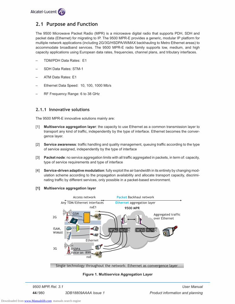
User Manual
Product information and planning
9500 MPR Rel. 3.1
3DB18809AAAA Issue 144/980
2.1 Purpose and Function
The 9500 Microwave Packet Radio (MPR) is a microwave digital radio that supports PDH, SDH and packet data (Ethernet) for migrating to IP. The 9500 MPR-E provides a generic, modular IP platform for multiple network applications (including 2G/3G/HSDPA/WiMAX backhauling to Metro Ethernet areas) to accommodate broadband services. The 9500 MPR-E radio family supports low, medium, and high capacity applications using European data rates, frequencies, channel plans, and tributary interfaces.
– TDM/PDH Data Rates: E1
– SDH Data Rates: STM-1
– ATM Data Rates: E1
– Ethernet Data Speed: 10, 100, 1000 Mb/s
– RF Frequency Range: 6 to 38 GHz
2.1.1 Innovative solutions
The 9500 MPR-E innovative solutions mainly are:
[1] Multiservice aggregation layer: the capacity to use Ethernet as a common transmission layer to transport any kind of traffic, independently by the type of interface. Ethernet becomes the conver-gence layer.
[2] Service awareness: traffic handling and quality management, queuing traffic according to the type of service assigned, independently by the type of interface
[3] Packet node: no service aggregation limits with all traffic aggregated in packets, in term of: capacity, type of service requirements and type of interface
[4] Service-driven adaptive modulation: fully exploit the air bandwidth in its entirety by changing mod-ulation scheme according to the propagation availability and allocate transport capacity, discrimi-nating traffic by different services, only possible in a packet-based environment.
[1] Multiservice aggregation layer
Figure 1. Multiservice Aggregation Layer
nxE1
Ethernet
ISAM, WiMAX
2GAggregated trafficover Ethernet
Packet Backhaul network
Ethernet aggregation layer
Access network
Any TDM/Ethernet interfaces
nxE1
3G HSDPAVoice on R99
9500 MPR
GSM
Single technology throughout the network: Ethernet as convergence layer
Downloaded from www.Manualslib.com manuals search engine

User Manual
Product information and planning
9500 MPR Rel. 3.1
3DB18809AAAA Issue 1 45/980
9500 MPR-E aggregates and carries over a COMMON PACKET LAYER: TDM 2G, 3G and IP/Ethernet. This allows sharing of common packet transmission infrastructures, regardless of the nature of carried traffic.
Due to the nature of Ethernet, each service can be discriminated based on several parameters like quality of service.
Mapping different access technologies over Ethernet is achieved by standardized protocols like circuit emulation and pseudo-wire.
[2] Service awareness
Figure 2. Service Awareness
Service awareness means the ability to discriminate the different traffic types carried over the converged Ethernet stream. The traffic flow can be composed by E1, STM-1, ATM and/or IP/Eth, coming from different sources, and therefore having different requirements.
For instance ATM traffic from a 3G base stations can carry voice (high priority, real time service) and data (lower priority and possibly non real time with high variability load, such as internet browsing, music download or video streaming).
Service awareness is what allows identifying the traffic types, and in case of the non real time variable bit rate one, optimize the band with overbooking of the radio scarce resource.
Downloaded from www.Manualslib.com manuals search engine

User Manual
Product information and planning
9500 MPR Rel. 3.1
3DB18809AAAA Issue 146/980
[3] Packet node
Figure 3. Packet Node
9500 MPR-E offers a SINGLE PACKET MATRIX able to switch, aggregate and handle any of the possible incoming traffic types with virtually no capacity limits (up to 10 GBps).
[4] Service-driven adaptive modulation
Figure 4. Service-driven Packet Adaptive Modulation
Traffic with high priority will always have bandwidth available, like voice (deterministic approach).
Broadband traffic is discriminated by QoS dynamically, with modulation scheme changes driven by propagation conditions.
Address new data services in the best way: packet natively
Downloaded from www.Manualslib.com manuals search engine
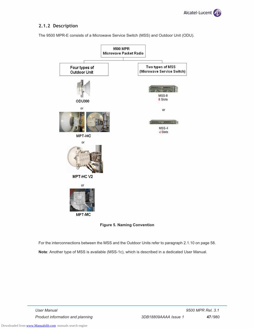
User Manual
Product information and planning
9500 MPR Rel. 3.1
3DB18809AAAA Issue 1 47/980
2.1.2 Description
The 9500 MPR-E consists of a Microwave Service Switch (MSS) and Outdoor Unit (ODU).
Figure 5. Naming Convention
For the interconnections between the MSS and the Outdoor Units refer to paragraph 2.1.10 on page 58.
Note: Another type of MSS is available (MSS-1c), which is described in a dedicated User Manual.
Downloaded from www.Manualslib.com manuals search engine

User Manual
Product information and planning
9500 MPR Rel. 3.1
3DB18809AAAA Issue 148/980
2.1.3 MSS Purpose, Function and Description
The MSS shelf houses the indoor cards. It is available in two versions:
– MSS-8– MSS-4
The MSS provides cross-connection, port aggregation, switching, and equipment management.
The MSS shelf consists of card cage and backplane in which mounts access and radio peripheral and Core-E control plug-in cards (see Figure 6. and Figure 7.).
Figure 6. MSS-8 shelf
Figure 7. MSS-4 shelf
The Core-E modules provide six Ethernet user interfaces (4 electrical interfaces as default + 2 electrical/optical interfaces available with optional SFP. Note: for the available SFPs refer to par. 2.8.1.3), the local WebEML interface and the local debug interface. The Main Core-E and the Spare Core-E modules have a different role.
The Main Core-E is always provided. It performs key node management and control functions, and provides various dc rails from the -48 Vdc input. It also incorporates a plug-in flash card, which holds node configuration and license data.
The Main Core-E also includes the cross-connection matrix, which implements all the cross-connections between the Transport modules, between the Ethernet user ports and between the Ethernet user ports and the Transport modules. The matrix is a standard Ethernet switch, based on VLAN, assigned by the WebEML.
The Ethernet ports of the Core-E can be configured in 2 ways:
1) to be used as GigaEthernet interface for Ethernet traffic (Note: for port#5 and port#6 the optional SFP must be installed);
2) to be used to connect an MPT: MPT-HC or MPT-MC to port#1 to port#4; an MPT-HC only to port#5 and port#6.
Transportmodule
Transportmodule
Transportmodule
Transportmodule
Transportmodule
Transport module or AUX peripheral module
Main Core-Emodule
Spare Core-Emodule
FANSmodule
Transportmodule
Transport module or AUX peripheral module
Main Core-Emodule
Spare Core-Emodule
FANSmodule
Downloaded from www.Manualslib.com manuals search engine

User Manual
Product information and planning
9500 MPR Rel. 3.1
3DB18809AAAA Issue 1 49/980
The Spare Core-E is an optional unit to provide aggregated traffic protection and control platform protection.
The following Transport modules are supported:
– TDM 32E1/DS1 local access module: provides the external interfaces for up to 32xE1 tributaries, manages the encapsulation/reconstruction of PDH data to/from standard Ethernet packets and sends/receives standard Ethernet packets to/from both Core-E modules; it contains the switch for the EPS Core-E protection and the DC/DC converter unit.
– STM-1 local access module: provides the external interfaces for up to 2 electrical or optical STM-1 signals, manages the encapsulation/reconstruction of SDH data to/from standard Ethernet packets and sends/receives standard Ethernet packets to/from both Core-E modules; it contains the switch for the EPS Core-E protection and the DC/DC converter unit.
– ASAP module: provides the external interfaces for up to 16xE1 tributaries carrying ATM cells, manages the encapsulation/reconstruction of ATM cells (according to the PWE3 standard) to/from standard Ethernet packets and sends/receives standard Ethernet packets to/from both Core-E modules; it contains the DC/DC converter unit.
– ODU300 Access module: this module is used to interface one ODU300. It sends/receives standard Ethernet packets to/from both Core-E modules, manages the radio frame (on Ethernet packet form) generation/termination, the interface to/from the alternate Radio module (for RPS management), the cable interface functions to ODU; it contains the logic for the EPS Core-E protection, the RPS logic and the DC/DC converter unit.For each radio direction with ODU300, one ODU300 Access module in the MSS and one associated ODU300 has to be provisioned in case of 1+0 radio configuration. Two radio access modules and two associated ODU300 have to be provisioned in case of 1+1 radio configurations.
– MPT Access (with PFoE) module: this module is used to interface up to two MPT-HC or the MPT-MC. This module provides the Power Feed over Ethernet to the MPT (only one cable to carry Ethernet traffic and power supply). The interface to the MPT-HC is a standard GbEth interface (electrical or optical) and a power supply cable. The interface to the MPT-MC is a standard GbEth interface (electrical). It sends/receives standard Ethernet packets to/from both Core-E modules. It contains the logic for the EPS Core-E protection and the DC/DC converter unit. For each radio direction with MPT, one MPT Access module in the MSS and one associated MPT has to be provisioned in case of 1+0 radio configuration. One (or two) MPT Access modules and two associated MPT have to be provisioned in case of 1+1 radio configurations.
– EAS Peripheral (P8ETH) module: provides access for customer Ethernet traffic.It supports the following traffic external interfaces:• 4xEthernet 10/100/1000 Base-T• 4xEthernet SFP 4x1000 Base-X optical, Base-T, or Copper Cable access directly available on
the EAS module. Interfaces can be 1000BASE-LX (GbE LX 10 km) or 1000BASE-SX (GbE SX 550 m) or 1000BASE-CX (GbE CX 25 m)
According to the transport modules installed different configurations can be implemented.
The optional AUX peripheral module provides 2x64 kbit/s service channels and the housekeeping alarms.
The optional +24 Vdc/-48 Vdc Converter module (to be installed in transport slot 4, 6 or 8 for MSS-8 and in transport slot 3 or 4 for MSS-4) can be used to power supply the MSS for +24 Vdc office applications.
A simplified block diagram of the MSS is shown in Figure 8. for MSS-8 and in Figure 9. for MSS-4.
Downloaded from www.Manualslib.com manuals search engine
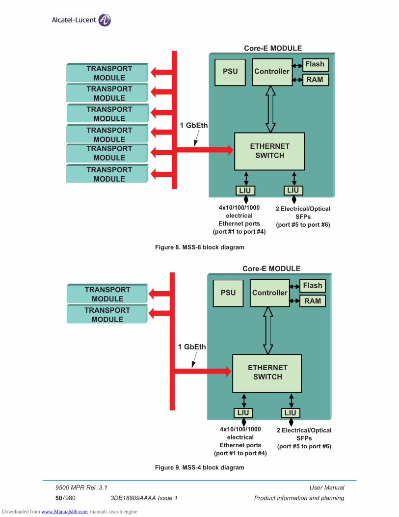
User Manual
Product information and planning
9500 MPR Rel. 3.1
3DB18809AAAA Issue 150/980
Figure 8. MSS-8 block diagram
Figure 9. MSS-4 block diagram
TRANSPORTMODULE
TRANSPORTMODULE
TRANSPORTMODULE
TRANSPORTMODULE
TRANSPORTMODULE
TRANSPORTMODULE
PSU ControllerFlash
RAM
ETHERNETSWITCH
Core-E MODULE
4x10/100/1000electrical
Ethernet ports(port #1 to port #4)
1 GbEth
LIU
2 Electrical/Optical SFPs
(port #5 to port #6)
LIU
TRANSPORTMODULE
TRANSPORTMODULE
PSU ControllerFlash
RAM
ETHERNETSWITCH
Core-E MODULE
1 GbEth
LIU LIU
4x10/100/1000electrical
Ethernet ports(port #1 to port #4)
2 Electrical/Optical SFPs
(port #5 to port #6)
Downloaded from www.Manualslib.com manuals search engine
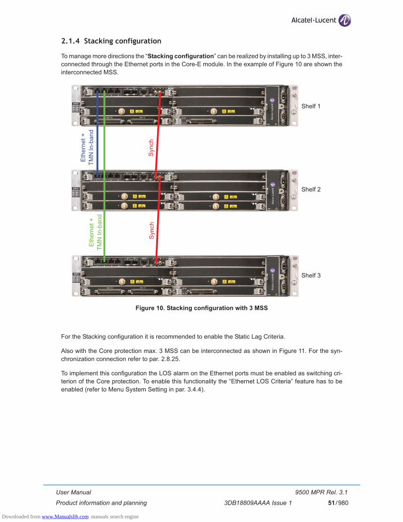
User Manual
Product information and planning
9500 MPR Rel. 3.1
3DB18809AAAA Issue 1 51/980
2.1.4 Stacking configuration
To manage more directions the “Stacking configuration” can be realized by installing up to 3 MSS, inter-connected through the Ethernet ports in the Core-E module. In the example of Figure 10 are shown the interconnected MSS.
Figure 10. Stacking configuration with 3 MSS
For the Stacking configuration it is recommended to enable the Static Lag Criteria.
Also with the Core protection max. 3 MSS can be interconnected as shown in Figure 11. For the syn-chronization connection refer to par. 2.8.25.
To implement this configuration the LOS alarm on the Ethernet ports must be enabled as switching cri-terion of the Core protection. To enable this functionality the “Ethernet LOS Criteria” feature has to be enabled (refer to Menu System Setting in par. 3.4.4).
Eth
erne
t +TM
N In
-ban
d
Syn
chS
ynch
Eth
erne
t +TM
N In
-ban
d
Shelf 1
Shelf 2
Shelf 3
Downloaded from www.Manualslib.com manuals search engine

User Manual
Product information and planning
9500 MPR Rel. 3.1
3DB18809AAAA Issue 152/980
Figure 11. Stacking configuration with 3 MSS with Core protection
Eth
erne
t +TM
N In
-ban
d
Eth
erne
t +TM
N In
-ban
d
Shelf 1
Shelf 2
Shelf 3
Eth
erne
t +TM
N In
-ban
d
Eth
erne
t +TM
N In
-ban
d
Downloaded from www.Manualslib.com manuals search engine
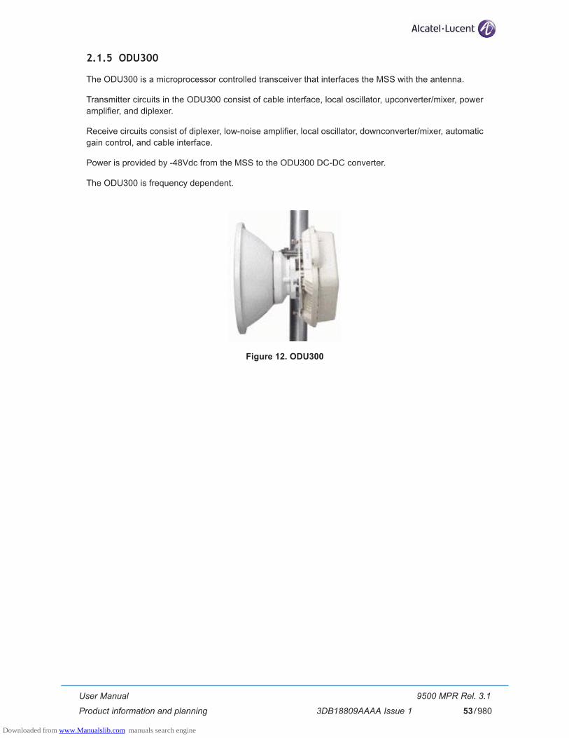
User Manual
Product information and planning
9500 MPR Rel. 3.1
3DB18809AAAA Issue 1 53/980
2.1.5 ODU300
The ODU300 is a microprocessor controlled transceiver that interfaces the MSS with the antenna.
Transmitter circuits in the ODU300 consist of cable interface, local oscillator, upconverter/mixer, power amplifier, and diplexer.
Receive circuits consist of diplexer, low-noise amplifier, local oscillator, downconverter/mixer, automatic gain control, and cable interface.
Power is provided by -48Vdc from the MSS to the ODU300 DC-DC converter.
The ODU300 is frequency dependent.
Figure 12. ODU300
Downloaded from www.Manualslib.com manuals search engine
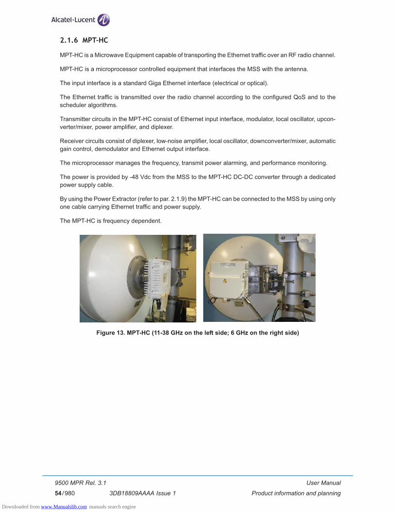
User Manual
Product information and planning
9500 MPR Rel. 3.1
3DB18809AAAA Issue 154/980
2.1.6 MPT-HC
MPT-HC is a Microwave Equipment capable of transporting the Ethernet traffic over an RF radio channel.
MPT-HC is a microprocessor controlled equipment that interfaces the MSS with the antenna.
The input interface is a standard Giga Ethernet interface (electrical or optical).
The Ethernet traffic is transmitted over the radio channel according to the configured QoS and to the scheduler algorithms.
Transmitter circuits in the MPT-HC consist of Ethernet input interface, modulator, local oscillator, upcon-verter/mixer, power amplifier, and diplexer.
Receiver circuits consist of diplexer, low-noise amplifier, local oscillator, downconverter/mixer, automatic gain control, demodulator and Ethernet output interface.
The microprocessor manages the frequency, transmit power alarming, and performance monitoring.
The power is provided by -48 Vdc from the MSS to the MPT-HC DC-DC converter through a dedicated power supply cable.
By using the Power Extractor (refer to par. 2.1.9) the MPT-HC can be connected to the MSS by using only one cable carrying Ethernet traffic and power supply.
The MPT-HC is frequency dependent.
Figure 13. MPT-HC (11-38 GHz on the left side; 6 GHz on the right side)
Downloaded from www.Manualslib.com manuals search engine
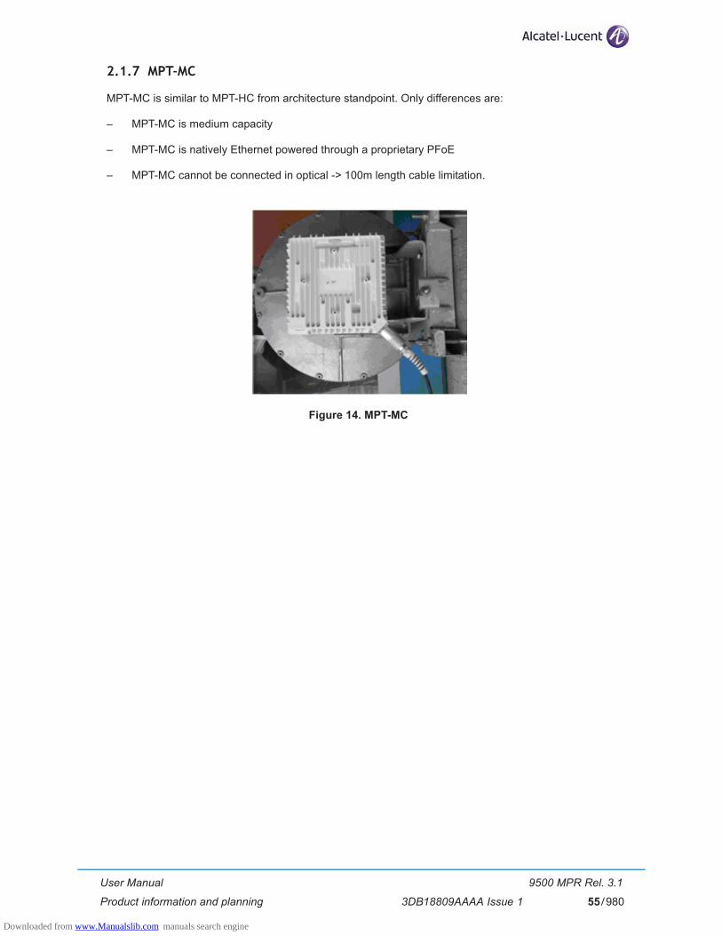
User Manual
Product information and planning
9500 MPR Rel. 3.1
3DB18809AAAA Issue 1 55/980
2.1.7 MPT-MC
MPT-MC is similar to MPT-HC from architecture standpoint. Only differences are:
– MPT-MC is medium capacity
– MPT-MC is natively Ethernet powered through a proprietary PFoE
– MPT-MC cannot be connected in optical -> 100m length cable limitation.
Figure 14. MPT-MC
Downloaded from www.Manualslib.com manuals search engine

User Manual
Product information and planning
9500 MPR Rel. 3.1
3DB18809AAAA Issue 156/980
2.1.8 MPT-HC V2
MPT-HC V2 is similar to MPT-HC from architecture standpoint and can be used as spare part of the MPT-HC. The differences are:
– MPT-HC V2 can be natively Ethernet powered through a proprietary PFoE (or as alternative by using two cables, one coaxial cable for the Power Supply and one optical cable for the Ethernet Traffic (as MPT-HC)
– MPT-HC V2 is XPIC-ready by the installation of a dedicated module.
Figure 15. MPT-HC V2
Downloaded from www.Manualslib.com manuals search engine

User Manual
Product information and planning
9500 MPR Rel. 3.1
3DB18809AAAA Issue 1 57/980
2.1.9 Power Extractor
The Power Extractor is an Outdoor Device, to be installed close to the MPT-HC, which receives on one cable the “Power Feed over Ethernet” (Ethernet traffic and Power Supply), provided by the MPT Access unit, and separates the Power Supply from the Ethernet traffic to be separately sent to the MPT-HC.
Figure 16. shows the Power Extractor.
Figure 16. Power Extractor
The Power Extractor has 3 connectors:
– DC+DATA In (PFoE from the MPT Access unit)
– DC Out (Power Supply to MPT-HC)
– Data Out (Ethernet traffic to MPT-HC)
Downloaded from www.Manualslib.com manuals search engine

User Manual
Product information and planning
9500 MPR Rel. 3.1
3DB18809AAAA Issue 158/980
2.1.10 MSS to Outdoor Unit interconnections
2.1.10.1 MSS to ODU300 interconnection
A single 50 ohm coaxial cable connects a ODU300 Modem unit to its ODU. The max. cable length is up to 150 m. ODU cable, connectors and grounding kits are separatly provided.
The ODU cable carries DC power supply for the ODU and five signals:
– Tx telemetry
– Reference signal to synchronize the ODU IQ Mod/Demod oscillator
– 311 MHz IQ modulated signal from the ODU300 Radio Interface (transmit IF)
– Rx telemetry
– 126 MHz IQ modulated signals from the ODU (receive IF)
Figure 17. MSS to ODU300 interconnection
Downloaded from www.Manualslib.com manuals search engine

User Manual
Product information and planning
9500 MPR Rel. 3.1
3DB18809AAAA Issue 1 59/980
2.1.10.2 MSS to MPT-HC interconnection
The MPT-HC can be connected in 4 different ways:
– Two cables (MPT Access unit to MPT-HC) - par. 2.1.10.2.1
– One cable (MPT Access unit to MPT-HC) - par. 2.1.10.2.2
– Two cables (Core-E unit to MPT-HC) - par. 2.1.10.2.3
– One cable (Core-E unit to MPT-HC) - par. 2.1.10.2.4
2.1.10.2.1 Two cables (MPT Access unit to MPT-HC)
Two cables connect an MPT-HC Access unit in the MSS to its MPT-HC (Figure 18 and Figure 19):
– One cable is a 50 ohm coaxial cable to send the power supply to the MPT-HC.
– The second cable is an Ethernet cable (optical or electrical).The max cable length for electrical Ethernet connection is 100 m.The max cable length for optical Ethernet connection is 450 m.The standard delivery is up to 300 m. The cable for up to 450 m is available on demand.
The Ethernet electrical cable is provided with connectors to be mounted on site with the specific RJ45 tool (1AD160490001). The Ethernet optical cable is preassembled and available in different lengths.
Figure 18. MSS to MPT-HC interconnection
Downloaded from www.Manualslib.com manuals search engine
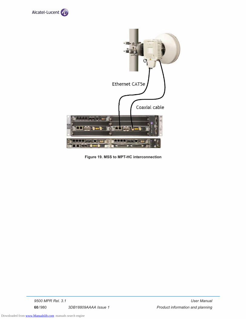
User Manual
Product information and planning
9500 MPR Rel. 3.1
3DB18809AAAA Issue 160/980
Figure 19. MSS to MPT-HC interconnection
Downloaded from www.Manualslib.com manuals search engine
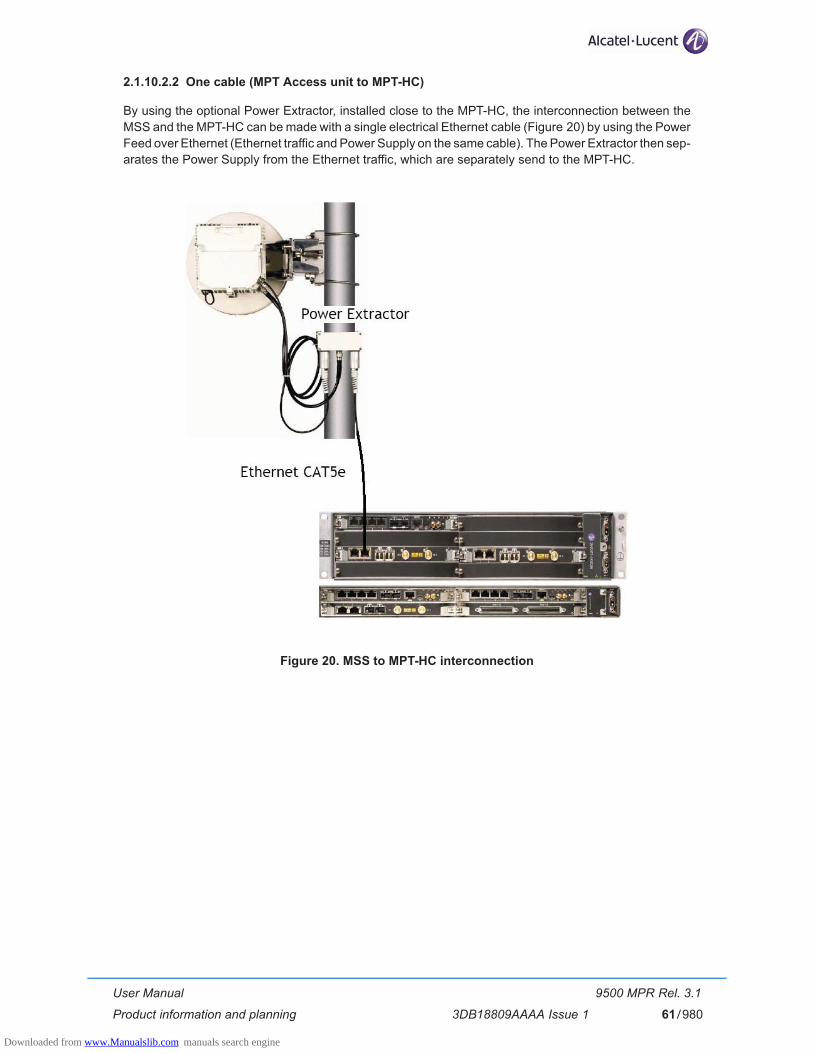
User Manual
Product information and planning
9500 MPR Rel. 3.1
3DB18809AAAA Issue 1 61/980
2.1.10.2.2 One cable (MPT Access unit to MPT-HC)
By using the optional Power Extractor, installed close to the MPT-HC, the interconnection between the MSS and the MPT-HC can be made with a single electrical Ethernet cable (Figure 20) by using the Power Feed over Ethernet (Ethernet traffic and Power Supply on the same cable). The Power Extractor then sep-arates the Power Supply from the Ethernet traffic, which are separately send to the MPT-HC.
Figure 20. MSS to MPT-HC interconnection
Downloaded from www.Manualslib.com manuals search engine

User Manual
Product information and planning
9500 MPR Rel. 3.1
3DB18809AAAA Issue 162/980
2.1.10.2.3 Two cables (Core-E unit to MPT-HC)
Two cables connect the MPT:
– one optical cable connected to port#5 or port #6 of the Core-E unit or one electrical cable connected to the electrical ports (port#1 to port#4) of the Core-E unit.
– a coaxial cable connected to the station battery to provide the power supply.
Figure 21. MSS to MPT-HC interconnection
Note: MPT-HC must be connected to a fuse or a breaker on a customer power distribution box. The recommended value is 3 Amps.
For the connection to the station battery refer to paragraph 2.1.10.4 on page 70.
Downloaded from www.Manualslib.com manuals search engine

User Manual
Product information and planning
9500 MPR Rel. 3.1
3DB18809AAAA Issue 1 63/980
2.1.10.2.4 One cable (Core-E unit to MPT-HC)
A possible option is to use only one single CAT5e cable. In this case the Power Injector is needed to merge DC+data and the Power Extractor is needed to separate them toward MPT-HC.
The max cable length is 100 m.
In Figure 22. and Figure 23. are shown the connections implemented with the two available Power Injec-tors.
The Power Injector box is an indoor device to be installed in a 19”/21” rack.
The Power Injector plug-in is a unit to be installed in an MSS.
Figure 22. MPT-HC connection through the Power Injector Box
Downloaded from www.Manualslib.com manuals search engine
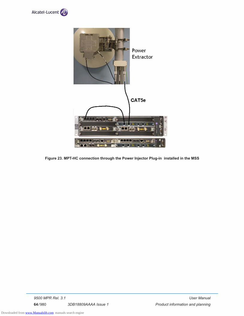
User Manual
Product information and planning
9500 MPR Rel. 3.1
3DB18809AAAA Issue 164/980
Figure 23. MPT-HC connection through the Power Injector Plug-in installed in the MSS
Downloaded from www.Manualslib.com manuals search engine

User Manual
Product information and planning
9500 MPR Rel. 3.1
3DB18809AAAA Issue 1 65/980
2.1.10.3 MSS to MPT-HC V2 interconnection
The MPT-HC V2 can be connected in 4 different ways:
– One cable (MPT Access unit to MPT-HC V2) - par. 2.1.10.3.1
– Two cables (MPT Access unit to MPT-HC V2) - par. 2.1.10.3.2
– Two cables (Core-E unit to MPT-HC V2) - par. 2.1.10.3.3
– One cable (Core-E unit to MPT-HC V2) - par. 2.1.10.3.4
2.1.10.3.1 One cable (MPT Access unit to MPT-HC V2)
One electrical Ethernet cable connects an MPT Access unit in the MSS to its MPT-HC V2 (the MPT Access unit provides the PFoE).
The max cable length is 100 m.
The Ethernet electrical cable is provided with connectors to be mounted on site with the specific RJ45 tool (1AD160490001).
Figure 24. MSS to MPT-HC V2 interconnection
Downloaded from www.Manualslib.com manuals search engine

User Manual
Product information and planning
9500 MPR Rel. 3.1
3DB18809AAAA Issue 166/980
2.1.10.3.2 Two cables (MPT Access unit to MPT-HC V2)
Two cables connect an MPT Access unit in the MSS to its MPT-HC V2:
– One cable is a 50 ohm coaxial cable to send the power supply to the MPT-HC V2:
• for length lower or equal to 100 m the power cable can be CAT5E cable to send the power sup-ply to the MPT-HC V2 . The Ethernet electrical cable is provided with connectors to be mounted on site with the specific RJ45 tool (1AD160490001);
• for length higher than 100m, the cable is a 50 ohm coaxial cable to send the power supply to the MPT-HC V2
Note: In case of length lower than 100m and presence in the field of 1 coaxial alredy installed�and free it is recomended to use the coax cable to minimise the installation effort.
– The second cable is an Ethernet optical cable.The Ethernet optical cable is preassembled and available in different lengths (up to 450 m).
Note: A special cord adapter must be connected to the coaxial cable on the MPT-HC V2.
Figure 25. MSS to MPT-HC V2 interconnection
Downloaded from www.Manualslib.com manuals search engine

User Manual
Product information and planning
9500 MPR Rel. 3.1
3DB18809AAAA Issue 1 67/980
2.1.10.3.3 Two cables (Core-E unit to MPT-HC V2)
Two cables connect the MPT:
– one optical cable connected to port#5 or port #6 of the Core-E unit or port #6 of the Core-E unit or one electrical cable connected to the electrical ports (port#1 to port#4) of the Core-E unit.
– a coaxial cable connected to the station battery to provide the power supply.
Figure 26. MSS to MPT-HC V2 interconnection
Note: MPT-HC V2 must be connected to a fuse or a breaker on a customer power distribution box. The recommended value is 3 Amps.
For the connection to the station battery refer to paragraph 2.1.10.4 on page 70.
Downloaded from www.Manualslib.com manuals search engine

User Manual
Product information and planning
9500 MPR Rel. 3.1
3DB18809AAAA Issue 168/980
2.1.10.3.4 One cable (Core-E unit to MPT-HC V2)
The MPT-HC V2 is connected to a Power Injector through one electrical Ethernet cable.
The max cable length is 100 m.
In Figure 31. and Figure 32. are shown the connections implemented with the two available Power Injec-tors.
The Power Injector box is an indoor device to be installed in a 19”/21” rack.
The Power Injector plug-in is a unit to be installed in the MSS.
Figure 27. MPT-HC V2 connection through the Power Injector Box
Downloaded from www.Manualslib.com manuals search engine

User Manual
Product information and planning
9500 MPR Rel. 3.1
3DB18809AAAA Issue 1 69/980
Figure 28. MPT-HC V2 connection through the Power Injector Plug-in installed in the MSS
Downloaded from www.Manualslib.com manuals search engine

User Manual
Product information and planning
9500 MPR Rel. 3.1
3DB18809AAAA Issue 170/980
2.1.10.4 How to connect the MPT-HC/MPT-HC V2 to the station battery
Figure 29. shows the devices used to connect an MPT directly to a battery.
From front to back:
– Coaxial cable with N connector
– Wall mount support 3CC50149AAXX (max 4 MPT)
– Lightning arrestor with its grounding cable
– Low pass filter
– Cable N to two wires ("pigtail")
Figure 29. MPT-HC/MPT-HC V2 directly connected to the battery
Downloaded from www.Manualslib.com manuals search engine

User Manual
Product information and planning
9500 MPR Rel. 3.1
3DB18809AAAA Issue 1 71/980
2.1.10.5 MSS to MPT-MC interconnection
The MPT-MC can be connected in 2 different ways:
– One cable (MPT Access unit to MPT-MC) - par. 2.1.10.5.1
– One cable (Core-E unit to MPT-MC) - par. 2.1.10.5.2
2.1.10.5.1 One cable (MPT Access unit to MPT-MC)
One electrical Ethernet cable connects an MPT Access unit in the MSS to its MPT-MC (the MPT Access unit provides the PFoE).
The max cable length is 100 m.
The Ethernet electrical cable is provided with connectors to be mounted on site with the specific RJ45 tool (1AD160490001).
Figure 30. MSS to MPT-MC interconnection
Downloaded from www.Manualslib.com manuals search engine

User Manual
Product information and planning
9500 MPR Rel. 3.1
3DB18809AAAA Issue 172/980
2.1.10.5.2 One cable (Core-E unit to MPT-MC)
The MPT-MC is connected to a Power Injector through one electrical Ethernet cable.
The max cable length is 100 m.
In Figure 31. and Figure 32. are shown the connections implemented with the two available Power Injec-tors.
The Power Injector box is an indoor device to be installed in a 19”/21” rack.
The Power Injector plug-in is a unit to be installed in a MSS.
Figure 31. MPT-MC connection through the Power Injector Box
Downloaded from www.Manualslib.com manuals search engine
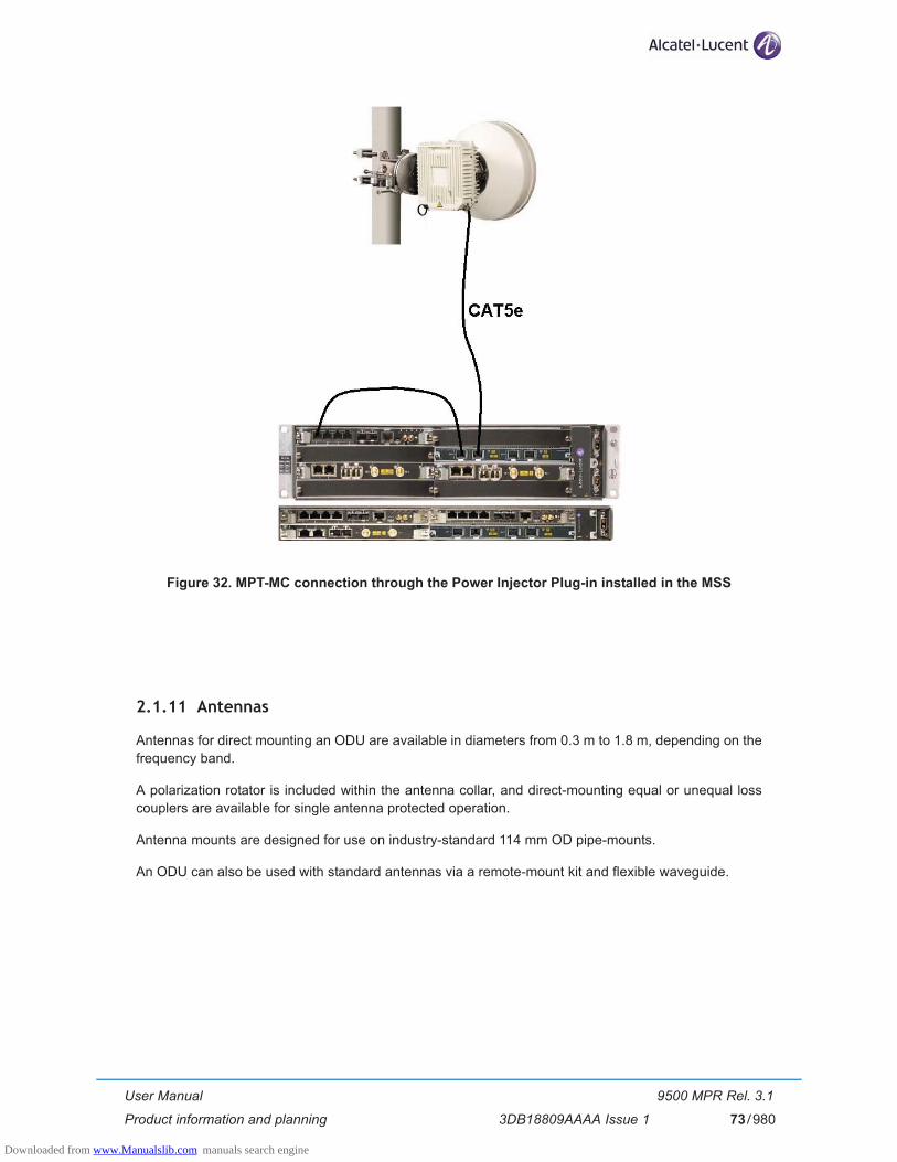
User Manual
Product information and planning
9500 MPR Rel. 3.1
3DB18809AAAA Issue 1 73/980
Figure 32. MPT-MC connection through the Power Injector Plug-in installed in the MSS
2.1.11 Antennas
Antennas for direct mounting an ODU are available in diameters from 0.3 m to 1.8 m, depending on the frequency band.
A polarization rotator is included within the antenna collar, and direct-mounting equal or unequal loss couplers are available for single antenna protected operation.
Antenna mounts are designed for use on industry-standard 114 mm OD pipe-mounts.
An ODU can also be used with standard antennas via a remote-mount kit and flexible waveguide.
Downloaded from www.Manualslib.com manuals search engine
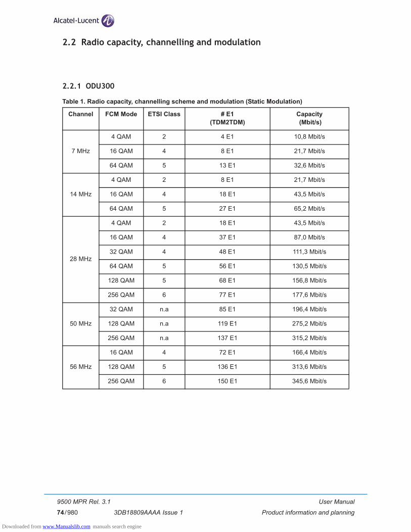
User Manual
Product information and planning
9500 MPR Rel. 3.1
3DB18809AAAA Issue 174/980
2.2 Radio capacity, channelling and modulation
2.2.1 ODU300
Table 1. Radio capacity, channelling scheme and modulation (Static Modulation)
Channel FCM Mode ETSI Class # E1 (TDM2TDM)
Capacity (Mbit/s)
7 MHz
4 QAM 2 4 E1 10,8 Mbit/s
16 QAM 4 8 E1 21,7 Mbit/s
64 QAM 5 13 E1 32,6 Mbit/s
14 MHz
4 QAM 2 8 E1 21,7 Mbit/s
16 QAM 4 18 E1 43,5 Mbit/s
64 QAM 5 27 E1 65,2 Mbit/s
28 MHz
4 QAM 2 18 E1 43,5 Mbit/s
16 QAM 4 37 E1 87,0 Mbit/s
32 QAM 4 48 E1 111,3 Mbit/s
64 QAM 5 56 E1 130,5 Mbit/s
128 QAM 5 68 E1 156,8 Mbit/s
256 QAM 6 77 E1 177,6 Mbit/s
50 MHz
32 QAM n.a 85 E1 196,4 Mbit/s
128 QAM n.a 119 E1 275,2 Mbit/s
256 QAM n.a 137 E1 315,2 Mbit/s
56 MHz
16 QAM 4 72 E1 166,4 Mbit/s
128 QAM 5 136 E1 313,6 Mbit/s
256 QAM 6 150 E1 345,6 Mbit/s
Downloaded from www.Manualslib.com manuals search engine
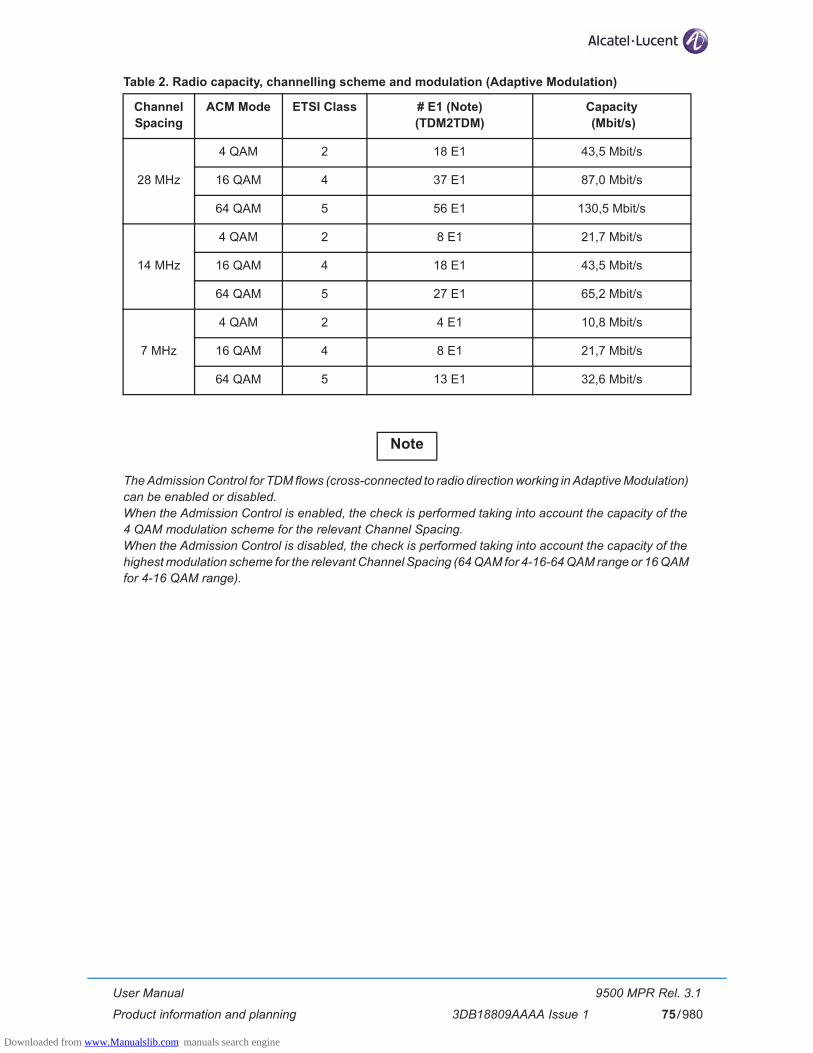
User Manual
Product information and planning
9500 MPR Rel. 3.1
3DB18809AAAA Issue 1 75/980
Table 2. Radio capacity, channelling scheme and modulation (Adaptive Modulation)
The Admission Control for TDM flows (cross-connected to radio direction working in Adaptive Modulation) can be enabled or disabled. �When the Admission Control is enabled, the check is performed taking into account the capacity of the 4 QAM modulation scheme for the relevant Channel Spacing. �When the Admission Control is disabled, the check is performed taking into account the capacity of the highest modulation scheme for the relevant Channel Spacing (64 QAM for 4-16-64 QAM range or 16 QAM for 4-16 QAM range).
Channel Spacing
ACM Mode ETSI Class # E1 (Note)(TDM2TDM)
Capacity (Mbit/s)
28 MHz
4 QAM 2 18 E1 43,5 Mbit/s
16 QAM 4 37 E1 87,0 Mbit/s
64 QAM 5 56 E1 130,5 Mbit/s
14 MHz
4 QAM 2 8 E1 21,7 Mbit/s
16 QAM 4 18 E1 43,5 Mbit/s
64 QAM 5 27 E1 65,2 Mbit/s
7 MHz
4 QAM 2 4 E1 10,8 Mbit/s
16 QAM 4 8 E1 21,7 Mbit/s
64 QAM 5 13 E1 32,6 Mbit/s
Note
Downloaded from www.Manualslib.com manuals search engine
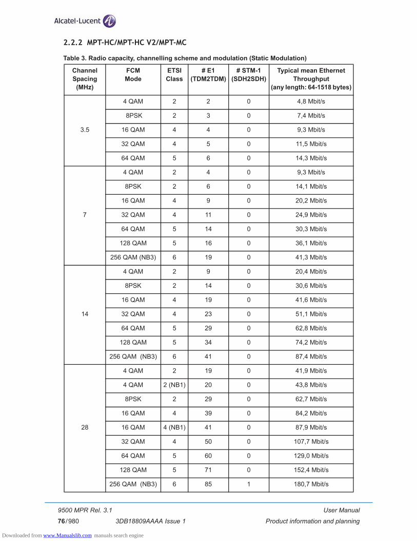
User Manual
Product information and planning
9500 MPR Rel. 3.1
3DB18809AAAA Issue 176/980
2.2.2 MPT-HC/MPT-HC V2/MPT-MC
Table 3. Radio capacity, channelling scheme and modulation (Static Modulation)
Channel Spacing
(MHz)
FCM Mode
ETSI Class
# E1(TDM2TDM)
# STM-1(SDH2SDH)
Typical mean Ethernet Throughput
(any length: 64-1518 bytes)
3.5
4 QAM 2 2 0 4,8 Mbit/s
8PSK 2 3 0 7,4 Mbit/s
16 QAM 4 4 0 9,3 Mbit/s
32 QAM 4 5 0 11,5 Mbit/s
64 QAM 5 6 0 14,3 Mbit/s
7
4 QAM 2 4 0 9,3 Mbit/s
8PSK 2 6 0 14,1 Mbit/s
16 QAM 4 9 0 20,2 Mbit/s
32 QAM 4 11 0 24,9 Mbit/s
64 QAM 5 14 0 30,3 Mbit/s
128 QAM 5 16 0 36,1 Mbit/s
256 QAM (NB3) 6 19 0 41,3 Mbit/s
14
4 QAM 2 9 0 20,4 Mbit/s
8PSK 2 14 0 30,6 Mbit/s
16 QAM 4 19 0 41,6 Mbit/s
32 QAM 4 23 0 51,1 Mbit/s
64 QAM 5 29 0 62,8 Mbit/s
128 QAM 5 34 0 74,2 Mbit/s
256 QAM (NB3) 6 41 0 87,4 Mbit/s
28
4 QAM 2 19 0 41,9 Mbit/s
4 QAM 2 (NB1) 20 0 43,8 Mbit/s
8PSK 2 29 0 62,7 Mbit/s
16 QAM 4 39 0 84,2 Mbit/s
16 QAM 4 (NB1) 41 0 87,9 Mbit/s
32 QAM 4 50 0 107,7 Mbit/s
64 QAM 5 60 0 129,0 Mbit/s
128 QAM 5 71 0 152,4 Mbit/s
256 QAM (NB3) 6 85 1 180,7 Mbit/s
Downloaded from www.Manualslib.com manuals search engine

User Manual
Product information and planning
9500 MPR Rel. 3.1
3DB18809AAAA Issue 1 77/980
N.B.1: New ETSI mask.
N.B.2: MPT-MC does not support this Channel Spacing.
N.B.3: MPT-MC does not support this FCM mode.
N.B.4: Applicable only for 6 GHz and 11 GHz RF bands.
40 (NB2) (NB4)
64 QAM 5 88 1 186,6 Mbit/s
128 QAM 5 104 1 220,6 Mbit/s
50
64 QAM n.a 110 1 234,2 Mbit/s
128 QAM n.a 130 1 276,3 Mbit/s
256 QAM (NB3) n.a 148 1 314,4 Mbit/s
56 (NB2)
4 QAM 2 (NB1) 37 0 80,5 Mbit/s
8PSK 2 (NB1) 56 0 120,2 Mbit/s
16 QAM 4 75 1 159,9 Mbit/s
16 QAM 4 (NB1) 76 1 161,9 Mbit/s
32 QAM 4 92 1 196,2 Mbit/s
64 QAM 5 119 1 252,6 Mbit/s
128 QAM 5 141 1 298,6 Mbit/s
256 QAM (NB3) 6 160 2 339,8 Mbit/s
Channel Spacing
(MHz)
FCM Mode
ETSI Class
# E1(TDM2TDM)
# STM-1(SDH2SDH)
Typical mean Ethernet Throughput
(any length: 64-1518 bytes)
Downloaded from www.Manualslib.com manuals search engine
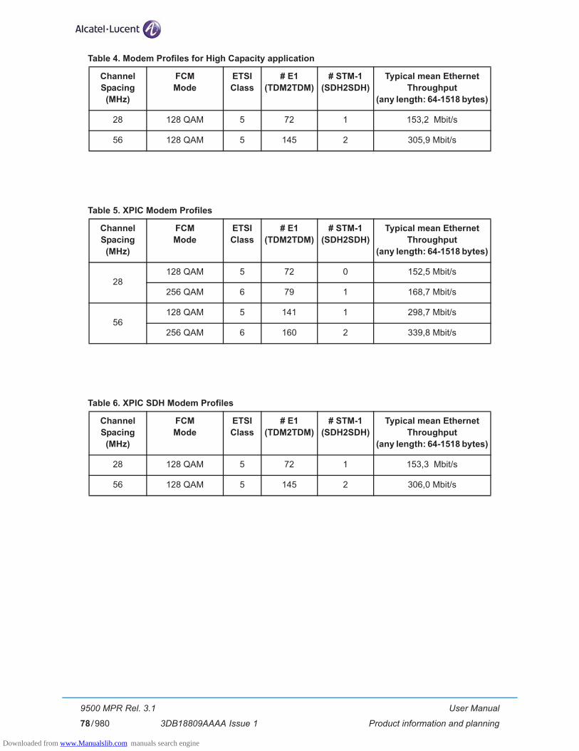
User Manual
Product information and planning
9500 MPR Rel. 3.1
3DB18809AAAA Issue 178/980
Table 4. Modem Profiles for High Capacity application
Table 5. XPIC Modem Profiles
Table 6. XPIC SDH Modem Profiles
Channel Spacing
(MHz)
FCM Mode
ETSI Class
# E1(TDM2TDM)
# STM-1(SDH2SDH)
Typical mean Ethernet Throughput
(any length: 64-1518 bytes)
28 128 QAM 5 72 1 153,2 Mbit/s
56 128 QAM 5 145 2 305,9 Mbit/s
Channel Spacing
(MHz)
FCM Mode
ETSI Class
# E1(TDM2TDM)
# STM-1(SDH2SDH)
Typical mean Ethernet Throughput
(any length: 64-1518 bytes)
28128 QAM 5 72 0 152,5 Mbit/s
256 QAM 6 79 1 168,7 Mbit/s
56128 QAM 5 141 1 298,7 Mbit/s
256 QAM 6 160 2 339,8 Mbit/s
Channel Spacing
(MHz)
FCM Mode
ETSI Class
# E1(TDM2TDM)
# STM-1(SDH2SDH)
Typical mean Ethernet Throughput
(any length: 64-1518 bytes)
28 128 QAM 5 72 1 153,3 Mbit/s
56 128 QAM 5 145 2 306,0 Mbit/s
Downloaded from www.Manualslib.com manuals search engine

User Manual
Product information and planning
9500 MPR Rel. 3.1
3DB18809AAAA Issue 1 79/980
Table 7. Radio capacity, channelling scheme and modulation (Adaptive Modulation)
N.B.1: MPT-MC does not support this Channel Spacing.
N.B.2: New ETSI mask.
Channel Spacing(MHz)
ACM ModeReference
ETSI Class
Modulation range Ethernet guaranteed rate(mean) (Mbps)
3.54 QAM 2 4 QAM to 64 QAM 4,8 Mbit/s
16 QAM 4 16 QAM to 64 QAM 9,3 Mbit/s
7
4 QAM 2 4 QAM to 256 QAM 9,3 Mbit/s
16 QAM 4 16 QAM to 256 QAM 20,2 Mbit/s
32 QAM 4 32 QAM to 256 QAM 24,9 Mbit/s
64 QAM 5 64 QAM to 256 QAM 30,3 Mbit/s
14
4 QAM 2 4 QAM to 256 QAM 20,4 Mbit/s
16 QAM 4 16 QAM to 256 QAM 41,6 Mbit/s
32 QAM 4 32 QAM to 256 QAM 51,1 Mbit/s
64 QAM 5 64 QAM to 256 QAM 62,8 Mbit/s
28
4 QAM 2 4 QAM to 256 QAM 41,9 Mbit/s
4 QAM 2 (NB2) 4 QAM to 256 QAM 43,8 Mbit/s
16 QAM 4 16 QAM to 256 QAM 84,2 Mbit/s
16 QAM 4 (NB2) 16 QAM to 256 QAM 87,9 Mbit/s
32 QAM 4 32 QAM to 256 QAM 107,7 Mbit/s
64 QAM 5 64 QAM to 256 QAM 129,0 Mbit/s
40 (NB1) 64 QAM 5 64 QAM to 256 QAM 186,6 Mbit/s
56 (NB1)
4 QAM 2 (NB2) 4 QAM to 256 QAM 80,5 Mbit/s
16 QAM 4 16 QAM to 256 QAM 159,9 Mbit/s
16 QAM 4 (NB2) 16 QAM to 256 QAM 161,9 Mbit/s
32 QAM 4 32 QAM to 256 QAM 196,2 Mbit/s
64 QAM 5 64 QAM to 256 QAM 252,6 Mbit/s
Downloaded from www.Manualslib.com manuals search engine

User Manual
Product information and planning
9500 MPR Rel. 3.1
3DB18809AAAA Issue 180/980
2.3 Standard Features
More radio and site scalability and flexibility for installation teams:
– Limited need for factory presetting channel frequency or bandwidth
– Interchangeable hardware units
– Supports cellular mobile networks, and microcellular network back and common carrier, private carrier and data networks, and utility haul applications.
– 2G, 2.5G, and 3G network compatible
– Intelligent indoor nodal unit that supports up to 12 outdoor units, expandable to 36 with the stacking configuration (with MPT)
– Flexible aggregate capacity sharing between E1, STM-1 and Ethernet
– Adaptive packet transport that improves performance for priority services
– Output power agility
– ATPC
– Adaptive Modulation
– XPIC
– Packet-based internal cross-connect
– E1 MEF8 encapsulation
– STM-1 encapsulation
– EoSDH feature
– ATM over PW according to RFC 4717
– Radio and Ethernet LAGs
– Ethernet Ring
– Electrical and optical GE interfaces
– Software-based configuration
– Multiservice Switching Capacity greater than 16 Gb/s
– No single point of failure
Downloaded from www.Manualslib.com manuals search engine

User Manual
Product information and planning
9500 MPR Rel. 3.1
3DB18809AAAA Issue 1 81/980
2.4 Radio Configurations
– 1+0
– 1+1 Hot-Standby (HSB)
• two types of coupler for ODU300:
– 3 dB/3 dB balanced coupler or 1.5 dB/6.0 dB unbalanced coupler
• two types of coupler for MPT-HC/MPT-MC:
– 3 dB/3 dB balanced coupler or 1 dB/10 dB unbalanced coupler
– 1+1 Hot-Standby Space Diversity (HSB SD) (no coupler)
– 1+1/2x(1+0) Frequency Diversity (FD) (co-polar)
– 1+1/2x(1+0) Frequency Diversity (FD) (cross-polar)
– 1+0/1+1 XPIC (with MPT-HC V2 only)
N.B. The 1+1 configuration with MPT-MC does not require any interconnection cable between the two ODUs. The protection is implemented by the “virtual cable” feature.
N.B. In 1+1 configuration the 2 Outdoor Units must be of the same types.
2.5 Typical System Configurations
– PDH/ATM Over Ethernet Packet Node - Mapping of 32 E1 and 16 E1 ATM on Ethernet (Figure 33.)
– PDH/SDH/ATM and Ethernet Terminal Packet Transport 32 E1, 2xSTM-1 and 16 E1 ATM Access, 1 Radio Direction (Figure 34.)
– PDH/SDH/ATM and Ethernet Add/Drop Packed Node-Ethernet and 32 E1, 2xSTM-1 and 16 E1 ATM Local Access, 1 Back Link, 1 Haul Link (Figure 35.)
– PDH/SDH/ATM and Ethernet Terminal Packet Node-Ethernet and 32 E1, 2xSTM-1 and 16 E1 ATM Local Access, 2 Back Links (Figure 36.)
– PDH/SDH/ATM and Ethernet Add/Drop Packet Node-Ethernet and 32 E1, 2xSTM-1 and 16 E1 ATM Local Access, 1 Back Link and 2 Haul Links (Figure 37.)
– PDH/SDH/ATM and Ethernet Add/Drop Packet Node-Ethernet and 32 E1, 2xSTM-1 and 16 E1 ATM Local Access, 2 Haul Links and 2 Back Links (Figure 38.)
N.B. Radio LAG and Ethernet LAGs can be created to increase the capacity and availability.
Downloaded from www.Manualslib.com manuals search engine
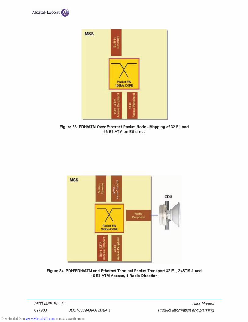
User Manual
Product information and planning
9500 MPR Rel. 3.1
3DB18809AAAA Issue 182/980
Figure 33. PDH/ATM Over Ethernet Packet Node - Mapping of 32 E1 and 16 E1 ATM on Ethernet
Figure 34. PDH/SDH/ATM and Ethernet Terminal Packet Transport 32 E1, 2xSTM-1 and 16 E1 ATM Access, 1 Radio Direction
2xS
TM-1
Acce
ss P
erip
hera
l
Downloaded from www.Manualslib.com manuals search engine
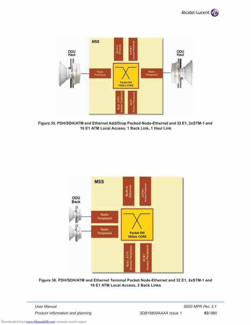
User Manual
Product information and planning
9500 MPR Rel. 3.1
3DB18809AAAA Issue 1 83/980
Figure 35. PDH/SDH/ATM and Ethernet Add/Drop Packed Node-Ethernet and 32 E1, 2xSTM-1 and 16 E1 ATM Local Access, 1 Back Link, 1 Haul Link
Figure 36. PDH/SDH/ATM and Ethernet Terminal Packet Node-Ethernet and 32 E1, 2xSTM-1 and 16 E1 ATM Local Access, 2 Back Links
2xS
TM-1
Acc
ess
Per
iphe
ral
2xS
TM-1
Acc
ess
Per
iphe
ral
Downloaded from www.Manualslib.com manuals search engine

User Manual
Product information and planning
9500 MPR Rel. 3.1
3DB18809AAAA Issue 184/980
Figure 37. PDH/SDH/ATM and Ethernet Add/Drop Packet Node-Ethernet and 32 E1, 2xSTM-1 and 16 E1 ATM Local Access, 1 Back Link and 2 Haul Links
Figure 38. PDH/SDH/ATM and Ethernet Add/Drop Packet Node-Ethernet and 32 E1, 2xSTM-1 and 16 E1 ATM Local Access, 2 Haul Links and 2 Back Links
2xS
TM-1
Acce
ss P
erip
hera
l
2
xSTM
-1Ac
cess
Per
iphe
ral
Downloaded from www.Manualslib.com manuals search engine

User Manual
Product information and planning
9500 MPR Rel. 3.1
3DB18809AAAA Issue 1 85/980
2.6 Environmental and Electrical Characteristics
– System Parameters (par. 2.6.1)
– ODU300 (par. 2.6.2)
– MPT-HC/MPT-HC V2 (par. 2.6.3)
– MPT-MC (par. 2.6.4)
– Radio performances (par. 2.6.5)
– General characteristics (Power Injector) (par. 2.6.6)
– General characteristics (Power Extractor) (par. 2.6.7)
2.6.1 System Parameters
General with ODU300
Operating Frequency Range 6 - 38 GHz
Max Ethernet throuput from 10 up to 310 Mbit/s
Modulation Options in FCM 4 QAM, 16 QAM, 32 QAM, 64 QAM, 128 QAM, 256 QAM
Adaptive Modulation 4 QAM, 16 QAM, 64 QAM,
General with MPT-HC/MPT-HC V2
Operating Frequency Range 6 - 38 GHz
Max Ethernet throuput 340 Mbit/s
Bandwidth up to 56 MHz
Modulation Options in FCM 4 QAM, 16 QAM, 32 QAM, 64 QAM, 128 QAM, 256 QAM
Adaptive Modulation 4 QAM, 16 QAM, 32 QAM, 64 QAM, 128 QAM, 256 QAM
General with MPT-MC
Operating Frequency Range 6 - 38 GHz
Max Ethernet throuput 155 Mbit/s
Bandwidth up to 28 MHz
Modulation Options in FCM 4 QAM, 16 QAM, 32 QAM, 64 QAM, 128 QAM
Adaptive Modulation 4 QAM, 16 QAM, 32 QAM, 64 QAM, 128 QAM
Radio Path Protection Options
Non Protected, 1+0Protected Hot Standby, 1+1Space Diversity, 1+1Frequency Diversity, 1+1XPIC 1+0/1+1 (with MPT-HC V2)Radio LAG with four radio channels (with MPT-HC/MPT-HC V2/MPT-MC)
Downloaded from www.Manualslib.com manuals search engine
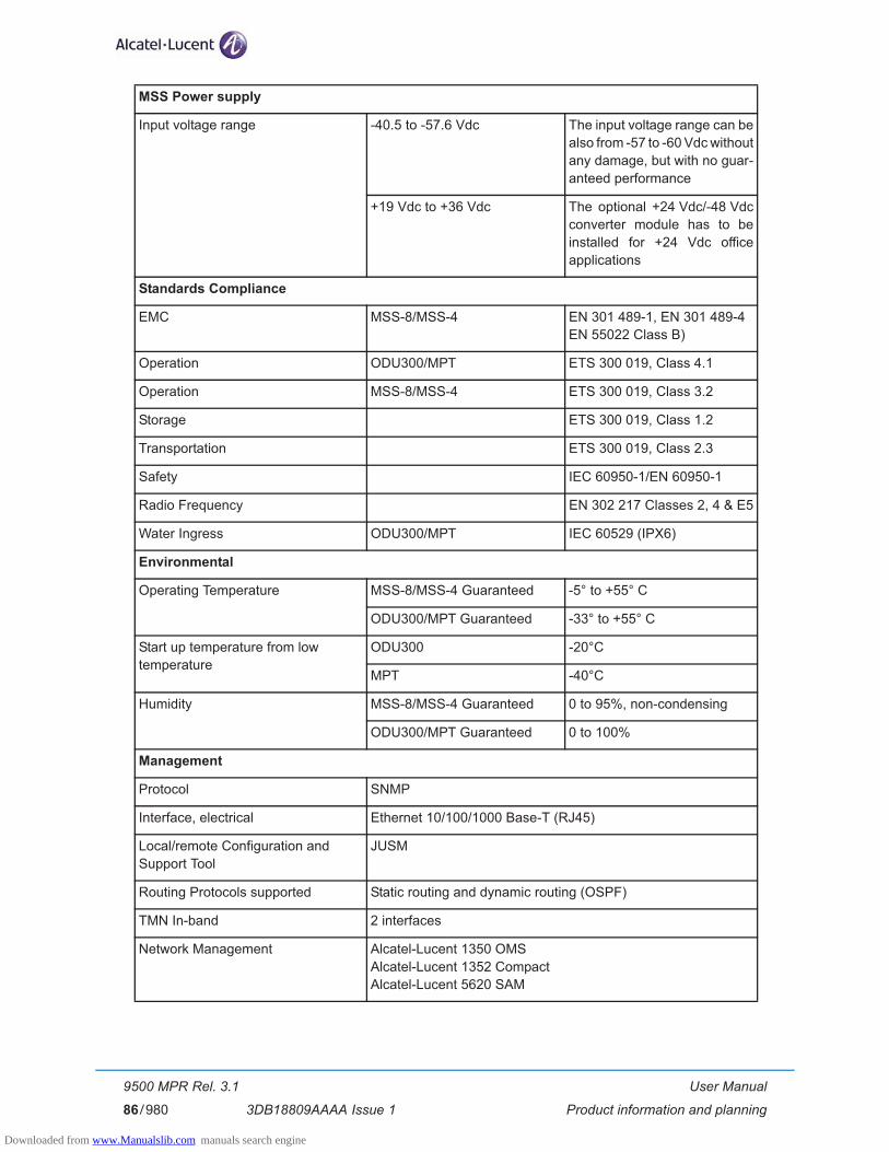
User Manual
Product information and planning
9500 MPR Rel. 3.1
3DB18809AAAA Issue 186/980
MSS Power supply
Input voltage range -40.5 to -57.6 Vdc The input voltage range can be also from -57 to -60 Vdc without any damage, but with no guar-anteed performance
+19 Vdc to +36 Vdc The optional +24 Vdc/-48 Vdc converter module has to be installed for +24 Vdc office applications
Standards Compliance
EMC MSS-8/MSS-4 EN 301 489-1, EN 301 489-4 EN 55022 Class B)
Operation ODU300/MPT ETS 300 019, Class 4.1
Operation MSS-8/MSS-4 ETS 300 019, Class 3.2
Storage ETS 300 019, Class 1.2
Transportation ETS 300 019, Class 2.3
Safety IEC 60950-1/EN 60950-1
Radio Frequency EN 302 217 Classes 2, 4 & E5
Water Ingress ODU300/MPT IEC 60529 (IPX6)
Environmental
Operating Temperature
MSS-8/MSS-4 Guaranteed -5° to +55° C
ODU300/MPT Guaranteed -33° to +55° C
Start up temperature from low �temperature
ODU300 -20°C
MPT -40°C
Humidity
MSS-8/MSS-4 Guaranteed 0 to 95%, non-condensing
ODU300/MPT Guaranteed 0 to 100%
Management
Protocol SNMP
Interface, electrical Ethernet 10/100/1000 Base-T (RJ45)
Local/remote Configuration and�Support Tool
JUSM
Routing Protocols supported Static routing and dynamic routing (OSPF)
TMN In-band 2 interfaces
Network Management Alcatel-Lucent 1350 OMSAlcatel-Lucent 1352 CompactAlcatel-Lucent 5620 SAM
Downloaded from www.Manualslib.com manuals search engine
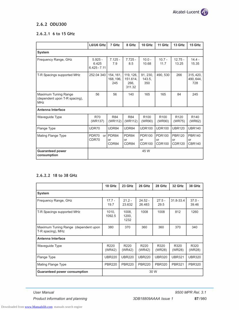
User Manual
Product information and planning
9500 MPR Rel. 3.1
3DB18809AAAA Issue 1 87/980
2.6.2 ODU300
2.6.2.1 6 to 15 GHz
2.6.2.2 18 to 38 GHz
L6/U6 GHz 7 GHz 8 GHz 10 GHz 11 GHz 13 GHz 15 GHz
System
Frequency Range, GHz 5.925 - 6.425
6.425 - 7.11
7.125 - 7.9
7.725 - 8.5
10.0 - 10.68
10.7 - 11.7
12.75 - 13.25
14.4 - 15.35
T-R Spacings supported MHz 252.04 340 154, 161, 168, 196,
245
119, 126, 151.614,
266, 311.32
91, 230, 143.5, 350
490, 530 266 315, 420, 490, 644,
728
Maximum Tuning Range (dependent upon T-R spacing), MHz
56 56 140 165 165 84 245
Antenna Interface
Waveguide Type R70 (WR137)
R84 (WR112)
R84 (WR112)
R100 (WR90)
R100 (WR90)
R120 (WR75)
R140 (WR62)
Flange Type UDR70 UDR84 UDR84 UDR100 UDR100 UBR120 UBR140
Mating Flange Type PDR70 or CDR70
PDR84 or CDR84
PDR84 or CDR84
PDR100 or CDR100
PDR100 or CDR100
PBR120 or CDR120
PBR140 or CBR140
Guaranteed power consumption
45 W
18 GHz 23 GHz 26 GHz 28 GHz 32 GHz 38 GHz
System
Frequency Range, GHz 17.7 - 19.7
21.2 - 23.632
24.52 - 26.483
27.5 - 29.5
31.8-33.4 37.0 - 39.46
T-R Spacings supported MHz 1010, 1092.5
1008, 1200, 1232
1008 1008 812 1260
Maximum Tuning Range (dependent upon T-R spacing), MHz
380 370 360 360 370 340
Antenna Interface
Waveguide Type R220 (WR42)
R220 (WR42)
R220 (WR42)
R320 (WR28)
R320 (WR28)
R320 (WR28)
Flange Type UBR220 UBR220 UBR220 UBR320 UBR321 UBR320
Mating Flange Type PBR220 PBR220 PBR220 PBR320 PBR321 PBR320
Guaranteed power consumption 30 W
Downloaded from www.Manualslib.com manuals search engine

User Manual
Product information and planning
9500 MPR Rel. 3.1
3DB18809AAAA Issue 188/980
2.6.3 MPT-HC/MPT-HC V2
2.6.3.1 6 to 13 GHz
2.6.3.2 15 to 38 GHz
L6 GHz U6 GHz 7 GHz 8 GHz 11 GHz 13 GHz
System
Frequency Range, GHz 5.925 - 6.425
6.425 - 7.11
7.125 - 7.9
7.725 - 8.5
10.7 - 11.7
12.75 - 13.25
T-R Spacings supported MHz 252.04 340 154, 161, 168,
196, 245
119; 126; 151.614;
208; 213,5; 266; 294; 305;
311.32
490-500-530
266
Antenna Interface
Waveguide Type WR137 WR137 WR112 WR113 WR75 WR62
Typical power consumption (MPT-HC) 38 W
Guaranteed power consumption (MPT-HC) 40 W
Typical power consumption (MPT-HC V2) 37 W
Guaranteed power consumption (MPT-HC V2) 39 W
Typical power consumption (MPT-HC V2 with RPS module)
38 W
Guaranteed power consumption (MPT-HC V2 with RPS module)
40 W
Typical power consumption (MPT-HC V2 with XPIC-RPS module)
45 W
Guaranteed power consumption (MPT-HC V2 with XPIC-RPS module)
47 W
15 GHz 18 GHz 23 GHz 26 GHz 38 GHz
System
Frequency Range, GHz 14.4 - 15.35
17.7 - 19.7
21.2 - 23.632
24.52 - 26.483
37.0 - 39.46
T-R Spacings supported MHz 308-315-322, 420, 490, 644,
728
1008-1010,
1560, 340
1008, 1050-1200-1232
1008 1260
Antenna Interface
Waveguide Type WR62 WR42 WR42 WR42 WR28
Downloaded from www.Manualslib.com manuals search engine
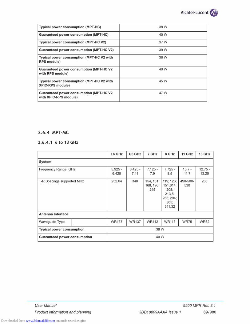
User Manual
Product information and planning
9500 MPR Rel. 3.1
3DB18809AAAA Issue 1 89/980
2.6.4 MPT-MC
2.6.4.1 6 to 13 GHz
Typical power consumption (MPT-HC) 38 W
Guaranteed power consumption (MPT-HC) 40 W
Typical power consumption (MPT-HC V2) 37 W
Guaranteed power consumption (MPT-HC V2) 39 W
Typical power consumption (MPT-HC V2 with RPS module)
38 W
Guaranteed power consumption (MPT-HC V2 with RPS module)
40 W
Typical power consumption (MPT-HC V2 with XPIC-RPS module)
45 W
Guaranteed power consumption (MPT-HC V2 with XPIC-RPS module)
47 W
L6 GHz U6 GHz 7 GHz 8 GHz 11 GHz 13 GHz
System
Frequency Range, GHz 5.925 - 6.425
6.425 - 7.11
7.125 - 7.9
7.725 - 8.5
10.7 - 11.7
12.75 - 13.25
T-R Spacings supported MHz 252.04 340 154, 161, 168, 196,
245
119; 126; 151.614;
208; 213,5;
266; 294; 305;
311.32
490-500-530
266
Antenna Interface
Waveguide Type WR137 WR137 WR112 WR113 WR75 WR62
Typical power consumption 38 W
Guaranteed power consumption 40 W
Downloaded from www.Manualslib.com manuals search engine
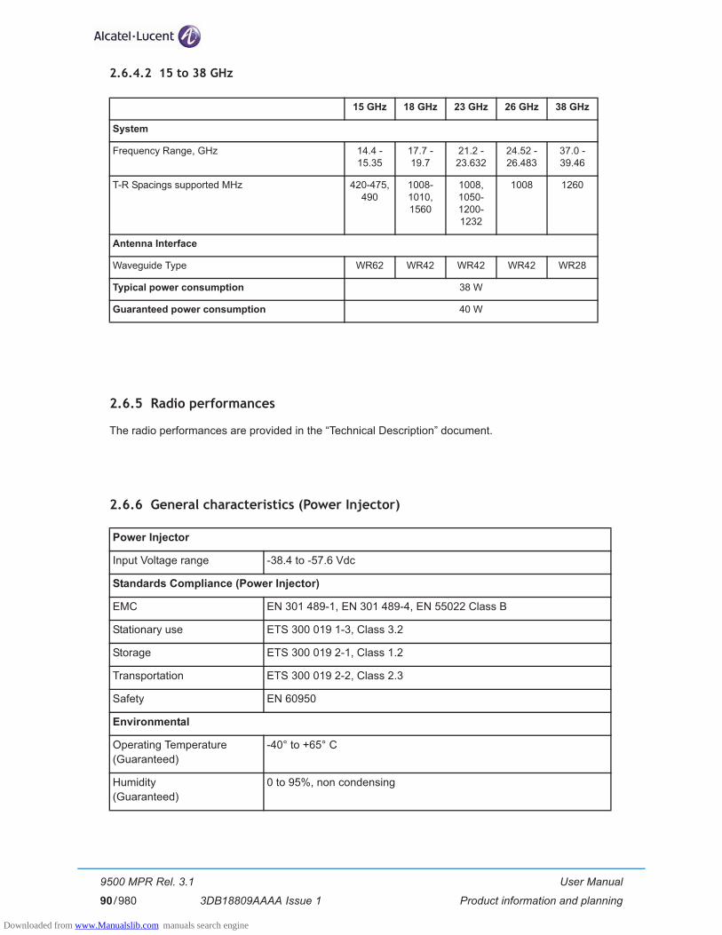
User Manual
Product information and planning
9500 MPR Rel. 3.1
3DB18809AAAA Issue 190/980
2.6.4.2 15 to 38 GHz
2.6.5 Radio performances
The radio performances are provided in the “Technical Description” document.
2.6.6 General characteristics (Power Injector)
15 GHz 18 GHz 23 GHz 26 GHz 38 GHz
System
Frequency Range, GHz 14.4 - 15.35
17.7 - 19.7
21.2 - 23.632
24.52 - 26.483
37.0 - 39.46
T-R Spacings supported MHz 420-475, 490
1008-1010, 1560
1008, 1050-1200-1232
1008 1260
Antenna Interface
Waveguide Type WR62 WR42 WR42 WR42 WR28
Typical power consumption 38 W
Guaranteed power consumption 40 W
Power Injector
Input Voltage range -38.4 to -57.6 Vdc
Standards Compliance (Power Injector)
EMC EN 301 489-1, EN 301 489-4, EN 55022 Class B
Stationary use ETS 300 019 1-3, Class 3.2
Storage ETS 300 019 2-1, Class 1.2
Transportation ETS 300 019 2-2, Class 2.3
Safety EN 60950
Environmental
Operating Temperature(Guaranteed)
-40° to +65° C
Humidity(Guaranteed)
0 to 95%, non condensing
Downloaded from www.Manualslib.com manuals search engine

User Manual
Product information and planning
9500 MPR Rel. 3.1
3DB18809AAAA Issue 1 91/980
2.6.7 General characteristics (Power Extractor)
Standards Compliance (Power Extractor)
EMC EN 301 489-1, EN 301 489-4, EN 55022 Class B
Stationary use ETS 300 019 2-4, Class 4M5 sinusoidal, random and shock
Storage ETS 300 019, Class 1.3
Transportation ETS 300 019 2-2, Class 2.3
Safety EN 60950
Environmental
Operating Temperature(Guaranteed)
-40° to +65° C
Start up temperature from low�temperature
-40° C
Humidity(Guaranteed)
0 to 100%
Downloaded from www.Manualslib.com manuals search engine

User Manual
Product information and planning
9500 MPR Rel. 3.1
3DB18809AAAA Issue 192/980
2.7 Parts Lists
2.7.1 Indoor items
Table 8. MSS item codes
APR Name APR Code Remarks
MSS-8 slot shelf 3DB18485AAXX
MSS-4 slot shelf 3DB18219ABXX
Core-E Card 3DB18326ABXX
Fan Card 3DB18134BAXX To be used in MSS-8
FAN1 Module 3DB18218ACXX To be used in MSS-4
STM-1 Access Card 3DB18735AAXX Up to 2 STM-1 signals
E1 Access Card 3DB18126ADXX Up to 32 E1 TDM stream
EAS Card 3DB18206ACXX Up to 8 Ethernet traffic interfaces. For the last four interfaces the dedicated SFP must be installed
ASAP Card 3DB18602AAXX Up to 16 E1 streams with ATM cells
AUX peripheral Card 3DB18236ABXX
Modem 300 Card 3DB18136ACXX To interface the ODU300 to be used with 56 MHz bandwidth (no adaptive modulation)
3DB18136ADXX
Modem 300EN Card 3DB18538AAXX To interface the ODU300 to be used with bandwidth up to 28 MHz (with or without adaptive modulation)
3DB18538ABXX
MPT Access Card (with PFoE) 3DB18634ABXX To interface one or two MPT-HC or MPT-MC or one MPT-HC and one MPT-MC
+24 Vdc/-48 Vdc Converter Card 3DB18763AAXX Two converters on the card for +24 Vdc office applications
+24 Vdc/-48 Vdc Converter Card 3DB18763ABXX One converter on the card for +24 Vdc office applications
+24 Vdc/-48 Vdc Converter 3DB18764AAXX To replace a failed converter on the +24 Vdc/-48 Vdc Converter Card
Front plate 3DB18163ABXX
SFP plug-in STM-1 L1.1 1AB194670005 To be installed in the STM-1 Access card (option)
SFP plug-in STM-1 S1.1 1AB194670007 To be installed in the STM-1 Access card (option)
SFP plug-in STM-1 Copper 1AB210170001 To be installed in the STM-1 Access card (option)
Downloaded from www.Manualslib.com manuals search engine

User Manual
Product information and planning
9500 MPR Rel. 3.1
3DB18809AAAA Issue 1 93/980
Table 9. Power Injector item codes
Table 10. Licence and software codes
SFP plug-in 1000Base-Lx 1AB383760002 To be installed in the Core-E card or EAS card (option)
SFP plug-in 1000Base-Sx 1AB383760001 To be installed in the Core-E card or EAS card or MPT Access Card (option)
SFP plug-in 1000Base-T(Copper Transceiver)
1AB359780002 To be installed in the Core-E card or EAS card (option)
SFP 2xE1 3DB78012AAAA To be installed in the Core-E card (option)
SFP S1.1 GE over STM-1 1AB380750003 To be installed in the Core-E card (option)
APR Name APR Code Remarks
Power Injector box 3CC50129AAXX To be installed in a 19”/21” rack to provide the PFoE to the MPT-MC
Power Injector plug-in 3CC50128AAXX To be installed in a MSS shelf to provide the PFoE to the MPT-MC or to the MPT-HC V2
Bracket 3DB77008ACXX Bracket to be used to install the Power Injector box in a 19” rack
21” Adapter kit 3CC50065AAAA Kit to be used with bracket item to install the Power Injector box in a 21” rack
APR name APR Code License String
Flash Cards 3.1.0
MPR Memory L6TD-210 3DB18659ABAA R/12Cap040
MPR Memory M1TD-210 3DB18660ABAA R/11Cap040/1Cap080
MPR Memory M2TD-210 3DB18661ABAA R/10Cap040/2Cap080
MPR Memory M6TD-210 3DB18662ABAA R/6Cap040/6Cap080
MPR Memory H1TD-210 3DB18663ABAA R/11Cap040/1Cap100
MPR Memory H2TD-210 3DB18664ABAA R/10Cap040/2Cap100
MPR Memory H6TD-210 3DB18666ABAA R/6Cap040/6Cap100
MPR Memory V1TD-210 3DB18667ABAA R/11Cap040/1Cap150
APR Name APR Code Remarks
Downloaded from www.Manualslib.com manuals search engine
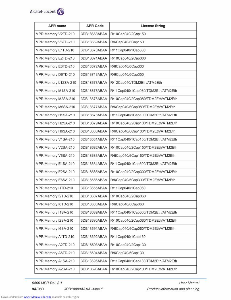
User Manual
Product information and planning
9500 MPR Rel. 3.1
3DB18809AAAA Issue 194/980
MPR Memory V2TD-210 3DB18668ABAA R/10Cap040/2Cap150
MPR Memory V6TD-210 3DB18669ABAA R/6Cap040/6Cap150
MPR Memory E1TD-210 3DB18670ABAA R/11Cap040/1Cap300
MPR Memory E2TD-210 3DB18671ABAA R/10Cap040/2Cap300
MPR Memory E6TD-210 3DB18672ABAA R/6Cap040/6Cap300
MPR Memory D6TD-210 3DB18718ABAA R/6Cap040/6Cap350
MPR Memory L12SA-210 3DB18673ABAA R/12Cap040/TDM2Eth/ATM2Eth
MPR Memory M1SA-210 3DB18675ABAA R/11Cap040/1Cap080/TDM2Eth/ATM2Eth
MPR Memory M2SA-210 3DB18676ABAA R/10Cap040/2Cap080/TDM2Eth/ATM2Eth
MPR Memory M6SA-210 3DB18677ABAA R/6Cap040/6Cap080/TDM2Eth/ATM2Eth
MPR Memory H1SA-210 3DB18678ABAA R/11Cap040/1Cap100/TDM2Eth/ATM2Eth
MPR Memory H2SA-210 3DB18679ABAA R/10Cap040/2Cap100/TDM2Eth/ATM2Eth
MPR Memory H6SA-210 3DB18680ABAA R/6Cap040/6Cap100/TDM2Eth/ATM2Eth
MPR Memory V1SA-210 3DB18681ABAA R/11Cap040/1Cap150/TDM2Eth/ATM2Eth
MPR Memory V2SA-210 3DB18682ABAA R/10Cap040/2Cap150/TDM2Eth/ATM2Eth
MPR Memory V6SA-210 3DB18683ABAA R/6Cap040/6Cap150/TDM2Eth/ATM2Eth
MPR Memory E1SA-210 3DB18684ABAA R/11Cap040/1Cap300/TDM2Eth/ATM2Eth
MPR Memory E2SA-210 3DB18685ABAA R/10Cap040/2Cap300/TDM2Eth/ATM2Eth
MPR Memory E6SA-210 3DB18686ABAA R/6Cap040/6Cap300/TDM2Eth/ATM2Eth
MPR Memory I1TD-210 3DB18665ABAA R/11Cap040/1Cap060
MPR Memory I2TD-210 3DB18687ABAA R/10Cap040/2Cap060
MPR Memory I6TD-210 3DB18688ABAA R/6Cap040/6Cap060
MPR Memory I1SA-210 3DB18689ABAA R/11Cap040/1Cap060/TDM2Eth/ATM2Eth
MPR Memory I2SA-210 3DB18690ABAA R/10Cap040/2Cap060/TDM2Eth/ATM2Eth
MPR Memory I6SA-210 3DB18691ABAA R/6Cap040/6Cap060/TDM2Eth/ATM2Eth
MPR Memory A1TD-210 3DB18692ABAA R/11Cap040/1Cap130
MPR Memory A2TD-210 3DB18693ABAA R/10Cap040/2Cap130
MPR Memory A6TD-210 3DB18694ABAA R/6Cap040/6Cap130
MPR Memory A1SA-210 3DB18695ABAA R/11Cap040/1Cap130/TDM2Eth/ATM2Eth
MPR Memory A2SA-210 3DB18696ABAA R/10Cap040/2Cap130/TDM2Eth/ATM2Eth
APR name APR Code License String
Downloaded from www.Manualslib.com manuals search engine
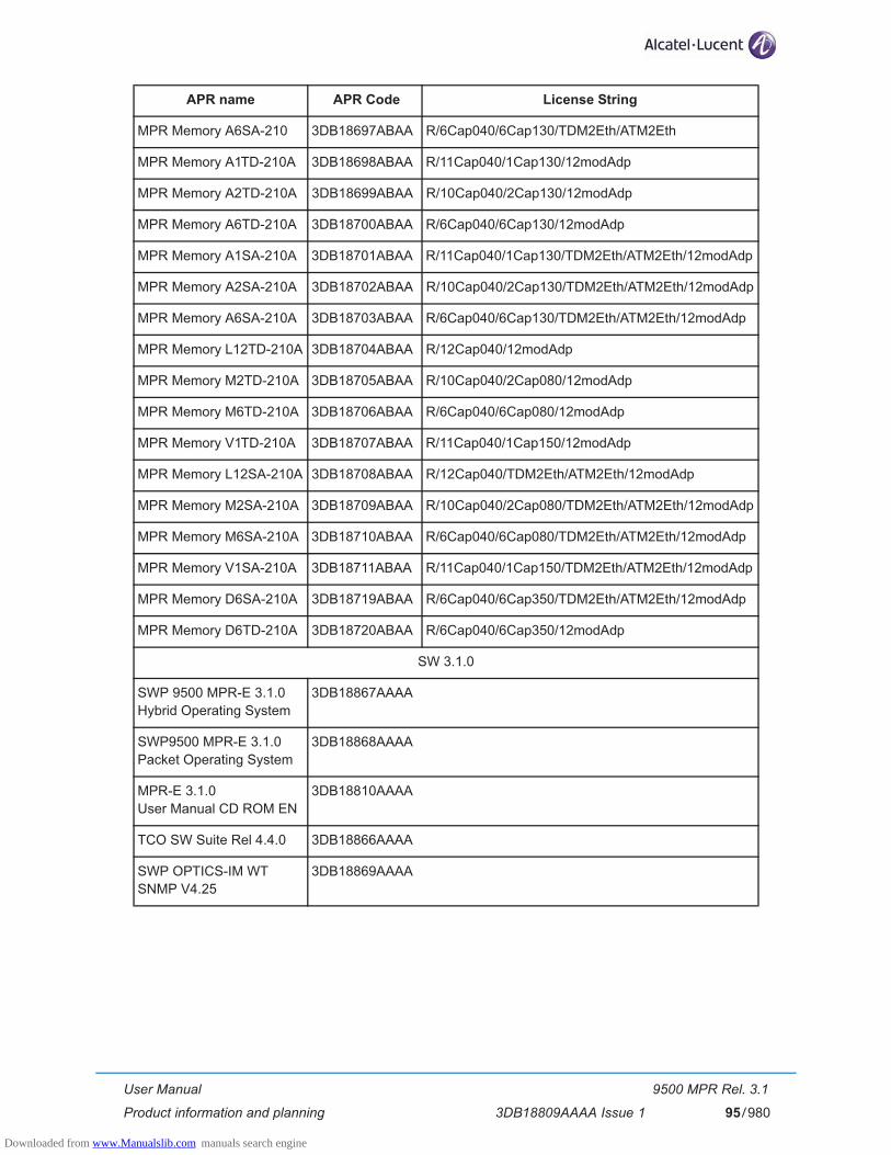
User Manual
Product information and planning
9500 MPR Rel. 3.1
3DB18809AAAA Issue 1 95/980
MPR Memory A6SA-210 3DB18697ABAA R/6Cap040/6Cap130/TDM2Eth/ATM2Eth
MPR Memory A1TD-210A 3DB18698ABAA R/11Cap040/1Cap130/12modAdp
MPR Memory A2TD-210A 3DB18699ABAA R/10Cap040/2Cap130/12modAdp
MPR Memory A6TD-210A 3DB18700ABAA R/6Cap040/6Cap130/12modAdp
MPR Memory A1SA-210A 3DB18701ABAA R/11Cap040/1Cap130/TDM2Eth/ATM2Eth/12modAdp
MPR Memory A2SA-210A 3DB18702ABAA R/10Cap040/2Cap130/TDM2Eth/ATM2Eth/12modAdp
MPR Memory A6SA-210A 3DB18703ABAA R/6Cap040/6Cap130/TDM2Eth/ATM2Eth/12modAdp
MPR Memory L12TD-210A 3DB18704ABAA R/12Cap040/12modAdp
MPR Memory M2TD-210A 3DB18705ABAA R/10Cap040/2Cap080/12modAdp
MPR Memory M6TD-210A 3DB18706ABAA R/6Cap040/6Cap080/12modAdp
MPR Memory V1TD-210A 3DB18707ABAA R/11Cap040/1Cap150/12modAdp
MPR Memory L12SA-210A 3DB18708ABAA R/12Cap040/TDM2Eth/ATM2Eth/12modAdp
MPR Memory M2SA-210A 3DB18709ABAA R/10Cap040/2Cap080/TDM2Eth/ATM2Eth/12modAdp
MPR Memory M6SA-210A 3DB18710ABAA R/6Cap040/6Cap080/TDM2Eth/ATM2Eth/12modAdp
MPR Memory V1SA-210A 3DB18711ABAA R/11Cap040/1Cap150/TDM2Eth/ATM2Eth/12modAdp
MPR Memory D6SA-210A 3DB18719ABAA R/6Cap040/6Cap350/TDM2Eth/ATM2Eth/12modAdp
MPR Memory D6TD-210A 3DB18720ABAA R/6Cap040/6Cap350/12modAdp
SW 3.1.0
SWP 9500 MPR-E 3.1.0�Hybrid Operating System
3DB18867AAAA
SWP9500 MPR-E 3.1.0�Packet Operating System
3DB18868AAAA
MPR-E 3.1.0�User Manual CD ROM EN
3DB18810AAAA
TCO SW Suite Rel 4.4.0 3DB18866AAAA
SWP OPTICS-IM WTSNMP V4.25
3DB18869AAAA
APR name APR Code License String
Downloaded from www.Manualslib.com manuals search engine

User Manual
Product information and planning
9500 MPR Rel. 3.1
3DB18809AAAA Issue 196/980
2.7.2 ODU300 (with internal lightning surge suppressor)
APR CODES Freq. TRsp (MHz)
Frequency Range
Description
3DB23216HAXX 6 GHz 340 6430-6590 ODU 300, 06GHz, T-R 340MHz, 6430-6590MHz, HP, TX LOW
3DB23216HBXX 6770-6930 ODU 300, 06GHz, T-R 340MHz, 6770-6930MHz, HP, TX HIGH
3DB23216HCXX 6515-6675 ODU 300, 06GHz, T-R 340MHz, 6515-6675MHz, HP, TX LOW
3DB23216HDXX 6855-7015 ODU 300, 06GHz, T-R 340MHz, 6855-7015MHz, HP, TX HIGH
3DB23216HEXX 6600-6760 ODU 300, 06GHz, T-R 340MHz, 6600-6760MHz, HP, TX LOW
3DB23216HFXX 6940-7100 ODU 300, 06GHz, T-R 340MHz, 6940-7100MHz, HP, TX HIGH
3DB23214HAXX 6 GHz 160/170
6540-6610 ODU 300, 06GHz, T-R 160/170MHz, 6540-6610MHz, HP, TX LOW
3DB23214HBXX 6710-6780 ODU 300, 06GHz, T-R 160/170MHz, 6710-6780MHz, HP, TX HIGH
3DB23214HCXX 6590-6660 ODU 300, 06GHz, T-R 160/170MHz, 6590-6660MHz, HP, TX LOW
3DB23214HDXX 6760-6830 ODU 300, 06GHz, T-R 160/170MHz, 6760-6830MHz, HP, TX HIGH
3DB23214HEXX 6640-6710 ODU 300, 06GHz, T-R 160/170MHz, 6640-6710MHz, HP, TX LOW
3DB23214HFXX 6800-6870 ODU 300, 06GHz, T-R 160/170MHz, 6800-6870MHz, HP, TX HIGH
3DB23215HAXX 6 GHz 252 5930-6020 ODU 300, 06GHz, T-R 252MHz, 5930-6020MHz, HHP, TX LOW
3DB23215HDXX 6182-6273 ODU 300, 06GHz, T-R 252MHz, 6182-6273MHz, HP TX HIGH
3DB23215HBXX 5989-6079 ODU 300, 06GHz, T-R 252MHz, 5989-6079MHz, HP, TX LOW
3DB23215HEXX 6241-6332 ODU 300, 06GHz, T-R 252MHz, 6241-6332MHz, HP, TX HIGH
3DB23215HCXX 6078-6168 ODU 300, 06GHz, T-R 252MHz, 6078-6168MHz, HP, TX LOW
3DB23215HFXX 6330-6421 ODU 300, 06GHz, T-R 252MHz, 6330-6421MHz, HP, TX HIGH
Downloaded from www.Manualslib.com manuals search engine

User Manual
Product information and planning
9500 MPR Rel. 3.1
3DB18809AAAA Issue 1 97/980
3DB23027HAXX 7 GHz 154 7184-7240 ODU 300, 07GHz, T-R 154MHz, 7184-7240MHz, HP, TX LOW
3DB23027HBXX 7338-7394 ODU 300, 07GHz, T-R 154MHz, 7338-7394MHz, HP, TX HIGH
3DB23028HBXX 7 GHz 161 7124-7184 ODU 300, 07GHz, T-R 161MHz, 7124-7184MHz, HP, TX LOW
3DB23028HGXX 7282-7342 ODU 300, 07GHz, T-R 161MHz, 7282-7342MHz, HP, TX HIGH
3DB23028HCXX 7170-7230 ODU 300, 07GHz, T-R 161MHz, 7170-7230MHz, HP, TX LOW
3DB23028HIXX 7331-7391 ODU 300, 07GHz, T-R 161MHz, 7331-7391MHz, HP TX HIGH
3DB23028HDXX 7208-7268 ODU 300, 07GHz, T-R 161MHz, 7208-7268MHz, HP, TX LOW
3DB23028HKXX 7366-7426 ODU 300, 07GHz, T-R 161MHz, 7366-7426MHz, HP, TX HIGH
3DB23028HOXX 7549-7606 ODU 300, 07GHz, T-R 161MHz, 7549-7606MHz, HP, TX LOW
3DB23028HRXX 7710-7767 ODU 300, 07GHz, T-R 161MHz, 7710-7767MHz, HP, TX HIGH
3DB23028HPXX 7598-7655 ODU 300, 07GHz, T-R 161MHz, 7598-7655MHz, HP, TX LOW
3DB23028HSXX 7759-7816 ODU 300, 07GHz, T-R 161MHz, 7759-7816MHz, HP, TX HIGH
3DB23028HQXX 7633-7690 ODU 300, 07GHz, T-R 161MHz, 7633-7690MHz, HP, TX LOW
3DB23028HTXX 7794-7851 ODU 300, 07GHz, T-R 161MHz, 7794-7851MHz, HP, TX HIGH
3DB23026HAXX 7 GHz 154/161/168
7424-7488 ODU 300, 07GHz, T-R 154/161/168MHz, 7424-7488MHz, HP, TX LOW
3DB23026HDXX 7581-7649 ODU 300, 07GHz, T-R 154/161/168MHz, 7581-7649MHz, HP, TX HIGH
3DB23026HBXX 7480-7544 ODU 300, 07GHz, T-R 154/161/168MHz, 7480-7544MHz, HP, TX LOW
3DB23026HEXX 7637-7705 ODU 300, 07GHz, T-R 154/161/168MHz, 7637-7705MHz, HP, TX HIGH
3DB23026HCXX 7512-7568 ODU 300, 07GHz, T-R 154/161/168MHz, 7512-7568MHz, HP, TX LOW
3DB23026HFXX 7666-7729 ODU 300, 07GHz, T-R 154/161/168MHz, 7666-7729MHz, HP, TX HIGH
APR CODES Freq. TRsp (MHz)
Frequency Range
Description
Downloaded from www.Manualslib.com manuals search engine

User Manual
Product information and planning
9500 MPR Rel. 3.1
3DB18809AAAA Issue 198/980
3DB23028HAXX 7 GHz 161 7114-7170 ODU 300, 07GHz, T-R 161MHz, 7114-7170MHZ, HP, TX LOW
3DB23028HFXX 7275-7331 ODU 300, 07GHz, T-R 161MHz, 7275-7331MHZ, HP, TX HIGH
3DB23028HUXX 7298-7358 ODU 300, 07GHZ, T-R 161MHZ, 7298-7358MHZ, HP, TX LOW
3DB23028HVXX 7459-7519 ODU 300, 07GHZ, T-R 161MHZ, 7459-7519MHZ, HP, TX HIGH
3DB23296HAXX 7125-7191 ODU 300, 07GHZ, T-R 161MHZ, 7125-7191MHZ, HP, TX LOW
3DB23296HBXX 7282-7352 ODU 300, 07GHZ, T-R 161MHZ, 7282-7352MHZ, HP, TX HIGH
3DB23296HCXX 7209-7275 ODU 300, 07GHZ, T-R 161MHZ, 7209-7275MHZ, HP, TX LOW
3DB23296HDXX 7367-7436 ODU 300, 07GHZ, T-R 161MHZ, 7367-7436MHZ, HP, TX HIGH
3DB23298HAXX 7 GHz 154/161/168
7480-7554 ODU 300, 07GHz, T-R 154/161/168MHz, 7480-7554MHz, HP, TX HIGH
3DB23299HAXX 7637-7715 ODU 300, 07GHz, T-R 154/161/168MHz, 7637-7715MHz, HP, TX HIGH
3DB23026HGXX 7421-7491 ODU 300, 07GHz, T-R 154/161/168MHz, 7421-7491MHz, HP, TX HIGH
3DB23026HHXX 7581-7652 ODU 300, 07GHz, T-R 154/161/168MHz, 7581-7652MHz, HP, TX HIGH
3DB23028HEXX 7 GHz 161 7247-7309 ODU 300, 07GHz, T-R 161/168MHz, 7247-7309MHz, HP, TX LOW
3DB23028HLXX 7408-7470 ODU 300, 07GHz, T-R 161/168MHz, 7408-7470MHz, HP, TX HIGH
3DB23028HWXX 7333,5-7393 ODU 300, 07GHz, T-R 161/168MHz, 7333,5-7393MHz, HP, TX LOW
3DB23028HXXX 7494,5-7554 ODU 300, 07GHz, T-R 161/168MHz, 7494,5-7554MHz, HP, TX HIGH
3DB23189HAXX 7 GHz 245 7428-7512 ODU 300, 07GHz, T-R 245MHz, 7428-7512MHz, HP, TX LOW
3DB23189HBXX 7673-7757 ODU 300, 07GHz, T-R 245MHz, 7673-7757MHz, HP, TX HIGH
APR CODES Freq. TRsp (MHz)
Frequency Range
Description
Downloaded from www.Manualslib.com manuals search engine
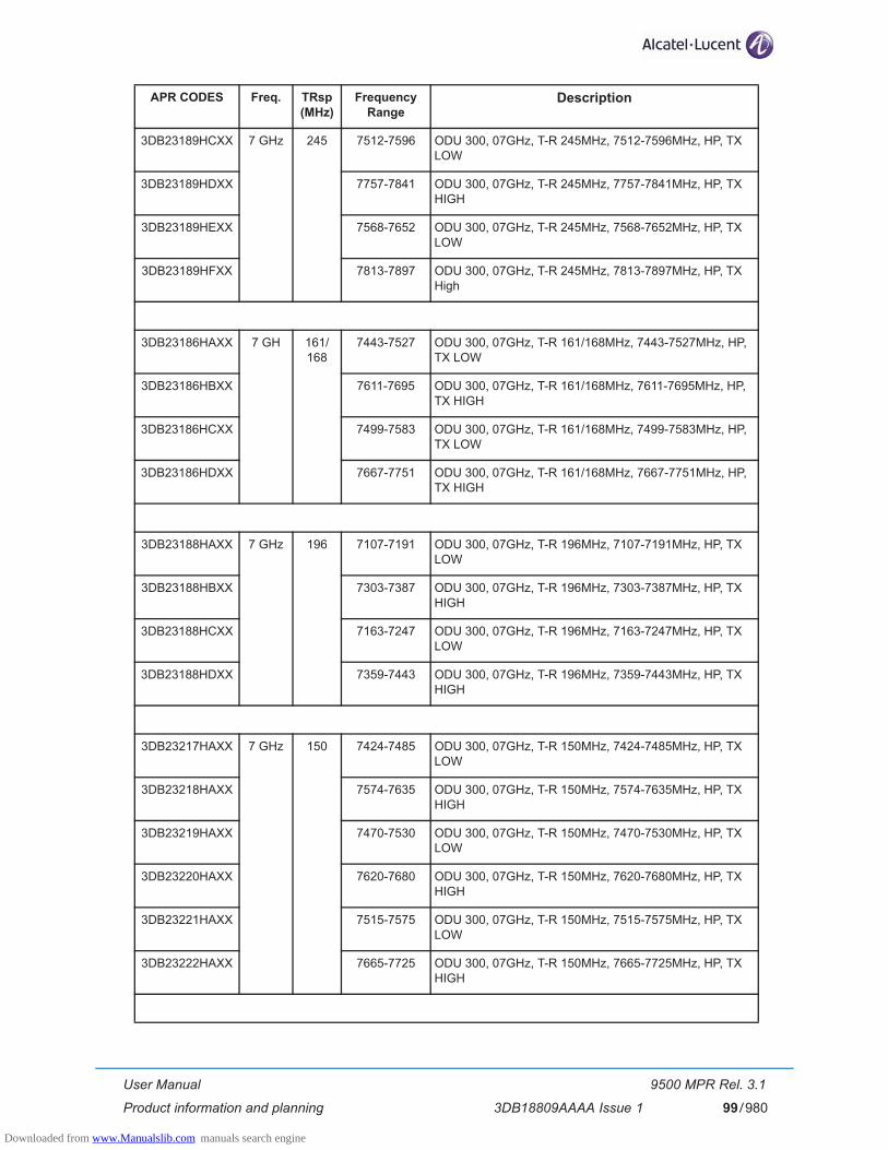
User Manual
Product information and planning
9500 MPR Rel. 3.1
3DB18809AAAA Issue 1 99/980
3DB23189HCXX 7 GHz 245 7512-7596 ODU 300, 07GHz, T-R 245MHz, 7512-7596MHz, HP, TX LOW
3DB23189HDXX 7757-7841 ODU 300, 07GHz, T-R 245MHz, 7757-7841MHz, HP, TX HIGH
3DB23189HEXX 7568-7652 ODU 300, 07GHz, T-R 245MHz, 7568-7652MHz, HP, TX LOW
3DB23189HFXX 7813-7897 ODU 300, 07GHz, T-R 245MHz, 7813-7897MHz, HP, TX High
3DB23186HAXX 7 GH 161/168
7443-7527 ODU 300, 07GHz, T-R 161/168MHz, 7443-7527MHz, HP, TX LOW
3DB23186HBXX 7611-7695 ODU 300, 07GHz, T-R 161/168MHz, 7611-7695MHz, HP, TX HIGH
3DB23186HCXX 7499-7583 ODU 300, 07GHz, T-R 161/168MHz, 7499-7583MHz, HP, TX LOW
3DB23186HDXX 7667-7751 ODU 300, 07GHz, T-R 161/168MHz, 7667-7751MHz, HP, TX HIGH
3DB23188HAXX 7 GHz 196 7107-7191 ODU 300, 07GHz, T-R 196MHz, 7107-7191MHz, HP, TX LOW
3DB23188HBXX 7303-7387 ODU 300, 07GHz, T-R 196MHz, 7303-7387MHz, HP, TX HIGH
3DB23188HCXX 7163-7247 ODU 300, 07GHz, T-R 196MHz, 7163-7247MHz, HP, TX LOW
3DB23188HDXX 7359-7443 ODU 300, 07GHz, T-R 196MHz, 7359-7443MHz, HP, TX HIGH
3DB23217HAXX 7 GHz 150 7424-7485 ODU 300, 07GHz, T-R 150MHz, 7424-7485MHz, HP, TX LOW
3DB23218HAXX 7574-7635 ODU 300, 07GHz, T-R 150MHz, 7574-7635MHz, HP, TX HIGH
3DB23219HAXX 7470-7530 ODU 300, 07GHz, T-R 150MHz, 7470-7530MHz, HP, TX LOW
3DB23220HAXX 7620-7680 ODU 300, 07GHz, T-R 150MHz, 7620-7680MHz, HP, TX HIGH
3DB23221HAXX 7515-7575 ODU 300, 07GHz, T-R 150MHz, 7515-7575MHz, HP, TX LOW
3DB23222HAXX 7665-7725 ODU 300, 07GHz, T-R 150MHz, 7665-7725MHz, HP, TX HIGH
APR CODES Freq. TRsp (MHz)
Frequency Range
Description
Downloaded from www.Manualslib.com manuals search engine

User Manual
Product information and planning
9500 MPR Rel. 3.1
3DB18809AAAA Issue 1100/980
3DB23223HAXX 7 GHz 175 7124-7185 ODU 300, 07GHz, T-R 175MHz, 7124-7185MHz, HP, TX LOW
3DB23224HAXX 7299-7360 ODU 300, 07GHz, T-R 175MHz, 7299-7360MHz, HP, TX HIGH
3DB23225HAXX 7157.5-7217.5 ODU 300, 07GHz, T-R 175MHz, 7157.5-7217.5MHz, HP, TX LOW
3DB23226HAXX 7332.5-7392.5 ODU 300, 07GHz, T-R 175MHz, 7332.5-7392.5MHz, HP, TX HIGH
3DB23227HAXX 7190-7250 ODU 300, 07GHz, T-R 175MHz, 7190-7250MHz, HP, TX LOW
3DB23228HAXX 7365-7425 ODU 300, 07GHz, T-R 175MHz, 7365-7425MHz, HP, TX HIGH
3DB23289HAXX 8 GHz 195 7718-7802 ODU 300, 08GHz, T-R 195MHz, 7718-7802MHz, HP, TX LOW
3DB23289HBXX 7913-7997 ODU 300, 08GHz, T-R 195MHz, 7913-7997MHz, HP, TX HIGH
3DB23033HEXX 8 GHz 300/310/
311.32/305.56
7722,5-7859 ODU 300, 08GHz, T-R 300/310/311.32/305.56MHz, 7722,5-7859MHz, HP, TX LOW
3DB23033HGXX 8025-8171 ODU 300, 08GHz, T-R 300/310/311.32/305.56MHz, 8025-8171MHz, HP, TX LOW
3DB23033HFXX 7844-7981 ODU 300, 08GHz, T-R 300/310/311.32/305.56MHz, 7844-7981MHz, HP, TX LOW
3DB23033HHXX 8145-8287 ODU 300, 08GHz, T-R 300/310/311.32/305.56MHz, 8145-8287MHz, HP, TX LOW
3DB23030HAXX 8 GHz 151 8204-8275 ODU 300, 08GHz, T-R 151MHz, 8204-8275MHz, HP, TX LOW
3DB23030HCXX 8355-8426 ODU 300, 08GHz, T-R 151MHz, 8355-8426MHz, HP, TX HIGH
3DB23030HBXX 8273-8345 ODU 300, 08GHz, T-R 151MHz, 8273-8345MHz, HP, TX LOW
3DB23030HDXX 8425-8496 ODU 300, 08GHz, T-R 151MHz, 8425-8496MHz, HP, TX HIGH
APR CODES Freq. TRsp (MHz)
Frequency Range
Description
Downloaded from www.Manualslib.com manuals search engine
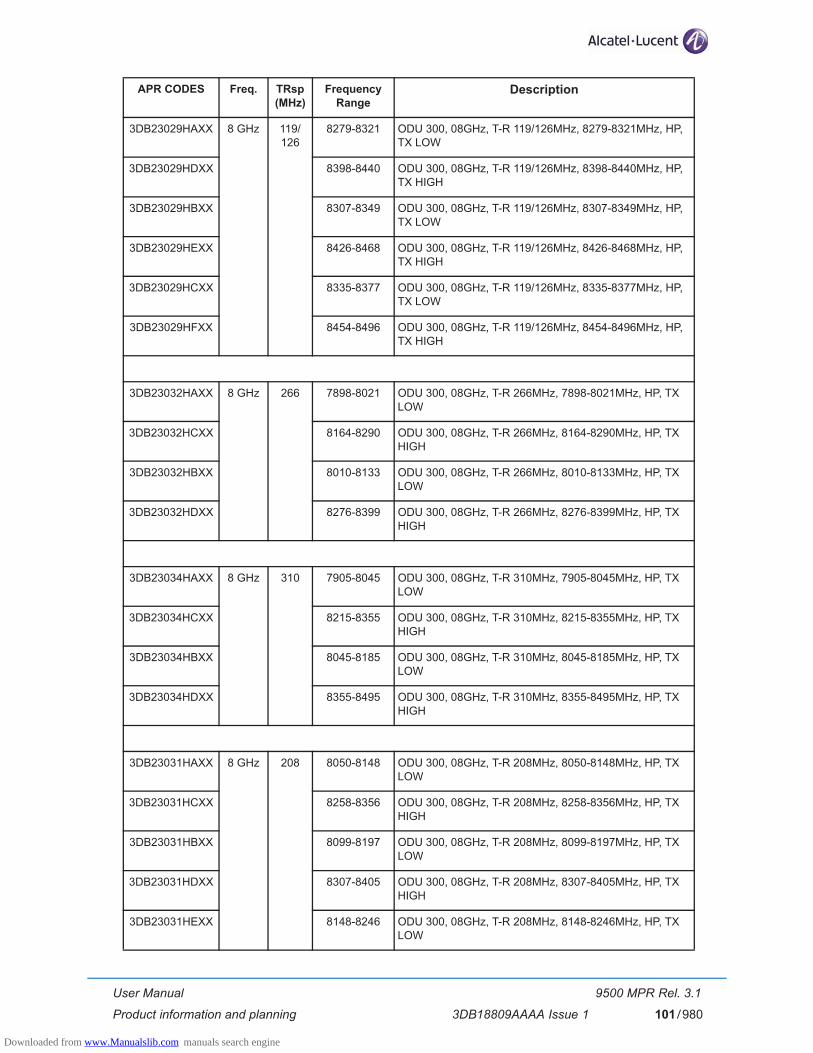
User Manual
Product information and planning
9500 MPR Rel. 3.1
3DB18809AAAA Issue 1 101/980
3DB23029HAXX 8 GHz 119/126
8279-8321 ODU 300, 08GHz, T-R 119/126MHz, 8279-8321MHz, HP, TX LOW
3DB23029HDXX 8398-8440 ODU 300, 08GHz, T-R 119/126MHz, 8398-8440MHz, HP, TX HIGH
3DB23029HBXX 8307-8349 ODU 300, 08GHz, T-R 119/126MHz, 8307-8349MHz, HP, TX LOW
3DB23029HEXX 8426-8468 ODU 300, 08GHz, T-R 119/126MHz, 8426-8468MHz, HP, TX HIGH
3DB23029HCXX 8335-8377 ODU 300, 08GHz, T-R 119/126MHz, 8335-8377MHz, HP, TX LOW
3DB23029HFXX 8454-8496 ODU 300, 08GHz, T-R 119/126MHz, 8454-8496MHz, HP, TX HIGH
3DB23032HAXX 8 GHz 266 7898-8021 ODU 300, 08GHz, T-R 266MHz, 7898-8021MHz, HP, TX LOW
3DB23032HCXX 8164-8290 ODU 300, 08GHz, T-R 266MHz, 8164-8290MHz, HP, TX HIGH
3DB23032HBXX 8010-8133 ODU 300, 08GHz, T-R 266MHz, 8010-8133MHz, HP, TX LOW
3DB23032HDXX 8276-8399 ODU 300, 08GHz, T-R 266MHz, 8276-8399MHz, HP, TX HIGH
3DB23034HAXX 8 GHz 310 7905-8045 ODU 300, 08GHz, T-R 310MHz, 7905-8045MHz, HP, TX LOW
3DB23034HCXX 8215-8355 ODU 300, 08GHz, T-R 310MHz, 8215-8355MHz, HP, TX HIGH
3DB23034HBXX 8045-8185 ODU 300, 08GHz, T-R 310MHz, 8045-8185MHz, HP, TX LOW
3DB23034HDXX 8355-8495 ODU 300, 08GHz, T-R 310MHz, 8355-8495MHz, HP, TX HIGH
3DB23031HAXX 8 GHz 208 8050-8148 ODU 300, 08GHz, T-R 208MHz, 8050-8148MHz, HP, TX LOW
3DB23031HCXX 8258-8356 ODU 300, 08GHz, T-R 208MHz, 8258-8356MHz, HP, TX HIGH
3DB23031HBXX 8099-8197 ODU 300, 08GHz, T-R 208MHz, 8099-8197MHz, HP, TX LOW
3DB23031HDXX 8307-8405 ODU 300, 08GHz, T-R 208MHz, 8307-8405MHz, HP, TX HIGH
3DB23031HEXX 8148-8246 ODU 300, 08GHz, T-R 208MHz, 8148-8246MHz, HP, TX LOW
APR CODES Freq. TRsp (MHz)
Frequency Range
Description
Downloaded from www.Manualslib.com manuals search engine

User Manual
Product information and planning
9500 MPR Rel. 3.1
3DB18809AAAA Issue 1102/980
3DB23031HFXX 8356-8454 ODU 300, 08GHz, T-R 208MHz,8356-8454MHz, HP, TX HIGH
3DB23303HAXX 8 GHz 360 7750-7900 ODU 300, 08GHz, T-R 360MHz, 7750-7900MHz, HP, TX LOW
3DB23304HAXX 8110-8260 ODU 300, 08GHz, T-R 360MHz, 8110-8260MHz, HP, TX HIGH
3DB23305HAXX 7870-8020 ODU 300, 08GHz, T-R 360MHz, 7870-8020MHz, HP, TX LOW
3DB23306HAXX 8230-8380 ODU 300, 08GHz, T-R 360MHz, 8230-8380MHz, HP, TX HIGH
3DB23307HAXX 7990-8140 ODU 300, 08GHz, T-R 360MHz, 7990-8140MHz, HP, TX HIGH
3DB23308HAXX 8350-8500 ODU 300, 08GHz, T-R 360MHz, 8350-8500MHz, HP, TX HIGH
3DB23261HAXX 10 GHz 350 10150.5-10252
ODU 300, 10GHz, T-R 350MHz, 10150.5-10252MHz, EP, TX LOW
3DB23261HBXX 10500.5-10602
ODU 300, 10GHz, T-R 350MHz, 10500.5-10602MHz, EP, TX HIGH
3DB23261HCXX 10196-10297.5
ODU 300, 10GHz, T-R 350MHz, 10196-10297.5MHz, EP, TX LOW
3DB23261HDXX 10546-10647.5
ODU 300, 10GHz, T-R 350MHz, 10546-10647.5MHz, EP, TX HIGH
3DB23255HAXX 10 GHz 91 10500.5-10516.3
ODU 300, 10GHz, T-R 91MHz, 10500.5-10516.3MHz, EP, TX LOW
3DB23255HBXX 10591.5-10607.3
ODU 300, 10GHz, T-R 91MHz, 10591.5-10607.3MHz, EP, TX HIGH
3DB23255HCXX 10514.5-10530.3
ODU 300, 10GHz, T-R 91MHz, 10514.5-10530.3MHz, EP, TX LOW
3DB23255HDXX 10605.5-10621.3
ODU 300, 10GHz, T-R 91MHz, 10605.5-10621.3MHz, EP, TX HIGH
3DB23255HEXX 10528.5-10544.3
ODU 300, 10GHz, T-R 91MHz, 10528.5-10544.3MHz, EP, TX LOW
3DB23255HFXX 10619.5-10635.3
ODU 300, 10GHz, T-R 91MHz, 10619.5-10635.3MHz, EP, TX HIGH
3DB23255HGXX 10542.5-10558.3
ODU 300, 10GHz, T-R 91MHz, 10542.5-10558.3MHz, EP, TX LOW
3DB23255HHXX 10633.5-10649.3
ODU 300, 10GHz, T-R 91MHz, 10633.5-10649.3MHz, EP, TX HIGH
APR CODES Freq. TRsp (MHz)
Frequency Range
Description
Downloaded from www.Manualslib.com manuals search engine
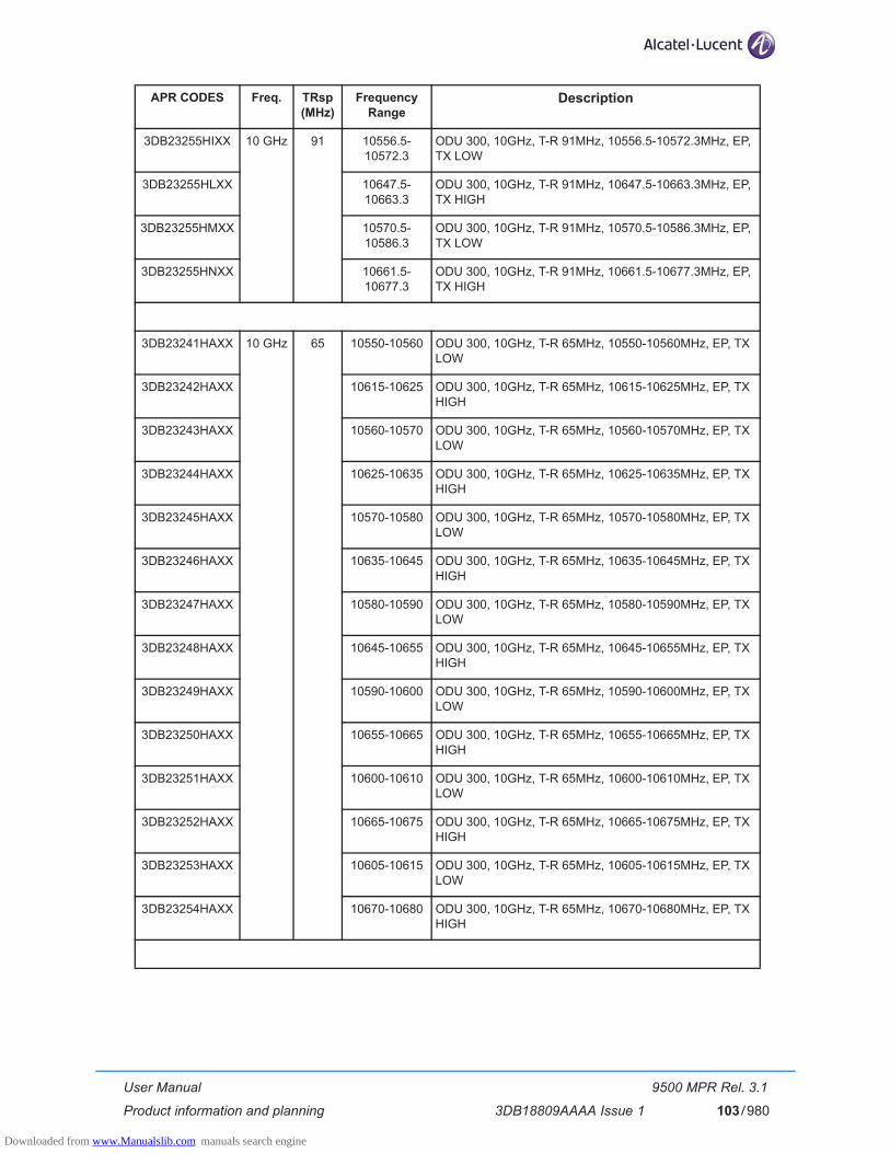
User Manual
Product information and planning
9500 MPR Rel. 3.1
3DB18809AAAA Issue 1 103/980
3DB23255HIXX 10 GHz 91 10556.5-10572.3
ODU 300, 10GHz, T-R 91MHz, 10556.5-10572.3MHz, EP, TX LOW
3DB23255HLXX 10647.5-10663.3
ODU 300, 10GHz, T-R 91MHz, 10647.5-10663.3MHz, EP, TX HIGH
3DB23255HMXX 10570.5-10586.3
ODU 300, 10GHz, T-R 91MHz, 10570.5-10586.3MHz, EP, TX LOW
3DB23255HNXX 10661.5-10677.3
ODU 300, 10GHz, T-R 91MHz, 10661.5-10677.3MHz, EP, TX HIGH
3DB23241HAXX 10 GHz 65 10550-10560 ODU 300, 10GHz, T-R 65MHz, 10550-10560MHz, EP, TX LOW
3DB23242HAXX 10615-10625 ODU 300, 10GHz, T-R 65MHz, 10615-10625MHz, EP, TX HIGH
3DB23243HAXX 10560-10570 ODU 300, 10GHz, T-R 65MHz, 10560-10570MHz, EP, TX LOW
3DB23244HAXX 10625-10635 ODU 300, 10GHz, T-R 65MHz, 10625-10635MHz, EP, TX HIGH
3DB23245HAXX 10570-10580 ODU 300, 10GHz, T-R 65MHz, 10570-10580MHz, EP, TX LOW
3DB23246HAXX 10635-10645 ODU 300, 10GHz, T-R 65MHz, 10635-10645MHz, EP, TX HIGH
3DB23247HAXX 10580-10590 ODU 300, 10GHz, T-R 65MHz, 10580-10590MHz, EP, TX LOW
3DB23248HAXX 10645-10655 ODU 300, 10GHz, T-R 65MHz, 10645-10655MHz, EP, TX HIGH
3DB23249HAXX 10590-10600 ODU 300, 10GHz, T-R 65MHz, 10590-10600MHz, EP, TX LOW
3DB23250HAXX 10655-10665 ODU 300, 10GHz, T-R 65MHz, 10655-10665MHz, EP, TX HIGH
3DB23251HAXX 10600-10610 ODU 300, 10GHz, T-R 65MHz, 10600-10610MHz, EP, TX LOW
3DB23252HAXX 10665-10675 ODU 300, 10GHz, T-R 65MHz, 10665-10675MHz, EP, TX HIGH
3DB23253HAXX 10605-10615 ODU 300, 10GHz, T-R 65MHz, 10605-10615MHz, EP, TX LOW
3DB23254HAXX 10670-10680 ODU 300, 10GHz, T-R 65MHz, 10670-10680MHz, EP, TX HIGH
APR CODES Freq. TRsp (MHz)
Frequency Range
Description
Downloaded from www.Manualslib.com manuals search engine
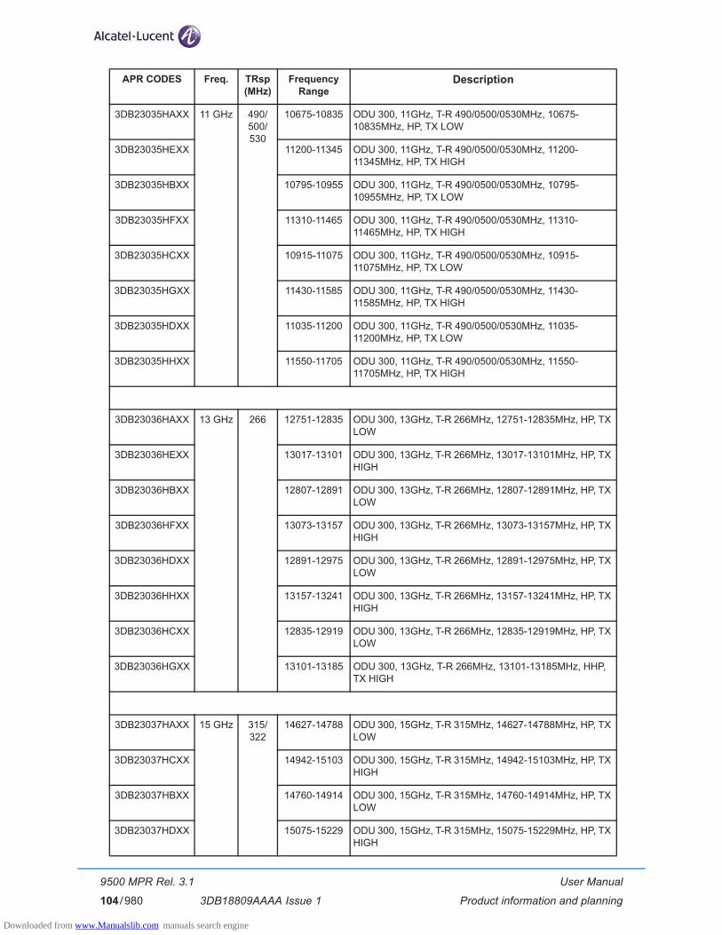
User Manual
Product information and planning
9500 MPR Rel. 3.1
3DB18809AAAA Issue 1104/980
3DB23035HAXX 11 GHz 490/500/530
10675-10835 ODU 300, 11GHz, T-R 490/0500/0530MHz, 10675-10835MHz, HP, TX LOW
3DB23035HEXX 11200-11345 ODU 300, 11GHz, T-R 490/0500/0530MHz, 11200-11345MHz, HP, TX HIGH
3DB23035HBXX 10795-10955 ODU 300, 11GHz, T-R 490/0500/0530MHz, 10795-10955MHz, HP, TX LOW
3DB23035HFXX 11310-11465 ODU 300, 11GHz, T-R 490/0500/0530MHz, 11310-11465MHz, HP, TX HIGH
3DB23035HCXX 10915-11075 ODU 300, 11GHz, T-R 490/0500/0530MHz, 10915-11075MHz, HP, TX LOW
3DB23035HGXX 11430-11585 ODU 300, 11GHz, T-R 490/0500/0530MHz, 11430-11585MHz, HP, TX HIGH
3DB23035HDXX 11035-11200 ODU 300, 11GHz, T-R 490/0500/0530MHz, 11035-11200MHz, HP, TX LOW
3DB23035HHXX 11550-11705 ODU 300, 11GHz, T-R 490/0500/0530MHz, 11550-11705MHz, HP, TX HIGH
3DB23036HAXX 13 GHz 266 12751-12835 ODU 300, 13GHz, T-R 266MHz, 12751-12835MHz, HP, TX LOW
3DB23036HEXX 13017-13101 ODU 300, 13GHz, T-R 266MHz, 13017-13101MHz, HP, TX HIGH
3DB23036HBXX 12807-12891 ODU 300, 13GHz, T-R 266MHz, 12807-12891MHz, HP, TX LOW
3DB23036HFXX 13073-13157 ODU 300, 13GHz, T-R 266MHz, 13073-13157MHz, HP, TX HIGH
3DB23036HDXX 12891-12975 ODU 300, 13GHz, T-R 266MHz, 12891-12975MHz, HP, TX LOW
3DB23036HHXX 13157-13241 ODU 300, 13GHz, T-R 266MHz, 13157-13241MHz, HP, TX HIGH
3DB23036HCXX 12835-12919 ODU 300, 13GHz, T-R 266MHz, 12835-12919MHz, HP, TX LOW
3DB23036HGXX 13101-13185 ODU 300, 13GHz, T-R 266MHz, 13101-13185MHz, HHP, TX HIGH
3DB23037HAXX 15 GHz 315/322
14627-14788 ODU 300, 15GHz, T-R 315MHz, 14627-14788MHz, HP, TX LOW
3DB23037HCXX 14942-15103 ODU 300, 15GHz, T-R 315MHz, 14942-15103MHz, HP, TX HIGH
3DB23037HBXX 14760-14914 ODU 300, 15GHz, T-R 315MHz, 14760-14914MHz, HP, TX LOW
3DB23037HDXX 15075-15229 ODU 300, 15GHz, T-R 315MHz, 15075-15229MHz, HP, TX HIGH
APR CODES Freq. TRsp (MHz)
Frequency Range
Description
Downloaded from www.Manualslib.com manuals search engine
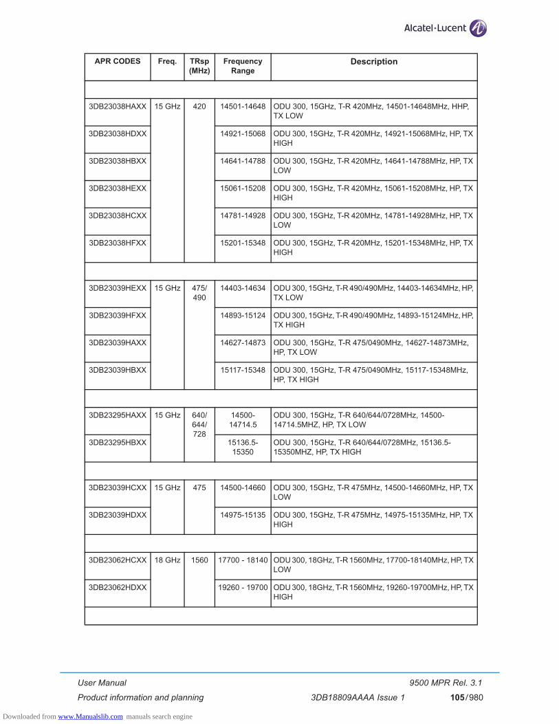
User Manual
Product information and planning
9500 MPR Rel. 3.1
3DB18809AAAA Issue 1 105/980
3DB23038HAXX 15 GHz 420 14501-14648 ODU 300, 15GHz, T-R 420MHz, 14501-14648MHz, HHP, TX LOW
3DB23038HDXX 14921-15068 ODU 300, 15GHz, T-R 420MHz, 14921-15068MHz, HP, TX HIGH
3DB23038HBXX 14641-14788 ODU 300, 15GHz, T-R 420MHz, 14641-14788MHz, HP, TX LOW
3DB23038HEXX 15061-15208 ODU 300, 15GHz, T-R 420MHz, 15061-15208MHz, HP, TX HIGH
3DB23038HCXX 14781-14928 ODU 300, 15GHz, T-R 420MHz, 14781-14928MHz, HP, TX LOW
3DB23038HFXX 15201-15348 ODU 300, 15GHz, T-R 420MHz, 15201-15348MHz, HP, TX HIGH
3DB23039HEXX 15 GHz 475/490
14403-14634 ODU 300, 15GHz, T-R 490/490MHz, 14403-14634MHz, HP, TX LOW
3DB23039HFXX 14893-15124 ODU 300, 15GHz, T-R 490/490MHz, 14893-15124MHz, HP, TX HIGH
3DB23039HAXX 14627-14873 ODU 300, 15GHz, T-R 475/0490MHz, 14627-14873MHz, HP, TX LOW
3DB23039HBXX 15117-15348 ODU 300, 15GHz, T-R 475/0490MHz, 15117-15348MHz, HP, TX HIGH
3DB23295HAXX 15 GHz 640/644/728
14500-14714.5
ODU 300, 15GHz, T-R 640/644/0728MHz, 14500-14714.5MHZ, HP, TX LOW
3DB23295HBXX 15136.5-15350
ODU 300, 15GHz, T-R 640/644/0728MHz, 15136.5-15350MHZ, HP, TX HIGH
3DB23039HCXX 15 GHz 475 14500-14660 ODU 300, 15GHz, T-R 475MHz, 14500-14660MHz, HP, TX LOW
3DB23039HDXX 14975-15135 ODU 300, 15GHz, T-R 475MHz, 14975-15135MHz, HP, TX HIGH
3DB23062HCXX 18 GHz 1560 17700 - 18140 ODU 300, 18GHz, T-R 1560MHz, 17700-18140MHz, HP, TX LOW
3DB23062HDXX 19260 - 19700 ODU 300, 18GHz, T-R 1560MHz, 19260-19700MHz, HP, TX HIGH
APR CODES Freq. TRsp (MHz)
Frequency Range
Description
Downloaded from www.Manualslib.com manuals search engine
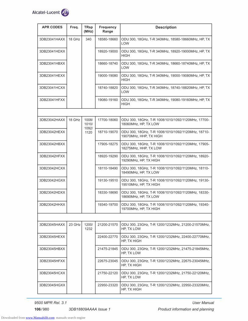
User Manual
Product information and planning
9500 MPR Rel. 3.1
3DB18809AAAA Issue 1106/980
3DB23041HAXX 18 GHz 340 18580-18660 ODU 300, 18GHz, T-R 340MHz, 18580-18660MHz, HP, TX LOW
3DB23041HDXX 18920-19000 ODU 300, 18GHz, T-R 340MHz, 18920-19000MHz, HP, TX HIGH
3DB23041HBXX 18660-18740 ODU 300, 18GHz, T-R 340MHz, 18660-18740MHz, HP, TX LOW
3DB23041HEXX 19000-19080 ODU 300, 18GHz, T-R 340MHz, 19000-19080MHz, HP, TX HIGH
3DB23041HCXX 18740-18820 ODU 300, 18GHz, T-R 340MHz, 18740-18820MHz, HP, TX LOW
3DB23041HFXX 19080-19160 ODU 300, 18GHz, T-R 340MHz, 19080-19160MHz, HP, TX HIGH
3DB23042HAXX 18 GHz 1008/1010/1092/1120
17700-18060 ODU 300, 18GHz, T-R 1008/1010/1092/1120MHz, 17700-18060MHz, HP, TX LOW
3DB23042HEXX 18710-19070 ODU 300, 18GHz, T-R 1008/1010/1092/1120MHz, 18710-19070MHz, HHP, TX HIGH
3DB23042HBXX 17905-18275 ODU 300, 18GHz, T-R 1008/1010/1092/1120MHz, 17905-18275MHz, HHP, TX LOW
3DB23042HFXX 18920-19290 ODU 300, 18GHz, T-R 1008/1010/1092/1120MHz, 18920-19290MHz, HP, TX HIGH
3DB23042HCXX 18110-18490 ODU 300, 18GHz, T-R 1008/1010/1092/1120MHz, 18110-18490MHz, HP, TX LOW
3DB23042HGXX 19130-19510 ODU 300, 18GHz, T-R 1008/1010/1092/1120MHz, 19130-19510MHz, HP, TX HIGH
3DB23042HDXX 18330-18690 ODU 300, 18GHz, T-R 1008/1010/1092/1120MHz, 18330-18690MHz, HP, TX LOW
3DB23042HHXX 19340-19700 ODU 300, 18GHz, T-R 1008/1010/1092/1120MHz, 19340-19700MHz, HP, TX HIGH
3DB23045HAXX 23 GHz 1200/1232
21200-21570 ODU 300, 23GHz, T-R 1200/1232MHz, 21200-21570MHz, HP, TX LOW
3DB23045HEXX 22400-22770 ODU 300, 23GHz, T-R 1200/1232MHz, 22400-22770MHz, HP, TX HIGH
3DB23045HBXX 21475-21845 ODU 300, 23GHz, T-R 1200/1232MHz, 21475-21845MHz, HP, TX LOW
3DB23045HFXX 22675-23045 ODU 300, 23GHz, T-R 1200/1232MHz, 22675-23045MHz, HP, TX HIGH
3DB23045HCXX 21750-22120 ODU 300, 23GHz, T-R 1200/1232MHz, 21750-22120MHz, HP, TX LOW
3DB23045HGXX 22950-23320 ODU 300, 23GHz, T-R 1200/1232MHz, 22950-23320MHz, HP, TX HIGH
APR CODES Freq. TRsp (MHz)
Frequency Range
Description
Downloaded from www.Manualslib.com manuals search engine
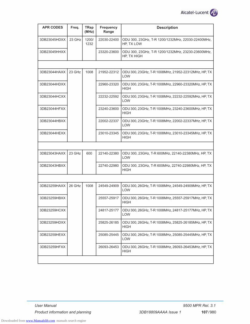
User Manual
Product information and planning
9500 MPR Rel. 3.1
3DB18809AAAA Issue 1 107/980
3DB23045HDXX 23 GHz 1200/1232
22030-22400 ODU 300, 23GHz, T-R 1200/1232MHz, 22030-22400MHz, HP, TX LOW
3DB23045HHXX 23320-23600 ODU 300, 23GHz, T-R 1200/1232MHz, 23230-23600MHz, HP, TX HIGH
3DB23044HAXX 23 GHz 1008 21952-22312 ODU 300, 23GHz, T-R 1008MHz, 21952-22312MHz, HP, TX LOW
3DB23044HDXX 22960-23320 ODU 300, 23GHz, T-R 1008MHz, 22960-23320MHz, HP, TX HIGH
3DB23044HCXX 22232-22592 ODU 300, 23GHz, T-R 1008MHz, 22232-22592MHz, HP, TX LOW
3DB23044HFXX 23240-23600 ODU 300, 23GHz, T-R 1008MHz, 23240-23600MHz, HP, TX HIGH
3DB23044HBXX 22002-22337 ODU 300, 23GHz, T-R 1008MHz, 22002-22337MHz, HP, TX LOW
3DB23044HEXX 23010-23345 ODU 300, 23GHz, T-R 1008MHz, 23010-23345MHz, HP, TX HIGH
3DB23043HAXX 23 GHz 600 22140-22380 ODU 300, 23GHz, T-R 600MHz, 22140-22380MHz, HP, TX LOW
3DB23043HBXX 22740-22980 ODU 300, 23GHz, T-R 600MHz, 22740-22980MHz, HP, TX HIGH
3DB23259HAXX 26 GHz 1008 24549-24909 ODU 300, 26GHz, T-R 1008MHz, 24549-24909MHz, HP, TX LOW
3DB23259HBXX 25557-25917 ODU 300, 26GHz, T-R 1008MHz, 25557-25917MHz, HP, TX HIGH
3DB23259HCXX 24817-25177 ODU 300, 26GHz, T-R 1008MHz, 24817-25177MHz, HP, TX LOW
3DB23259HDXX 25825-26185 ODU 300, 26GHz, T-R 1008MHz, 25825-26185MHz, HP, TX HIGH
3DB23259HEXX 25085-25445 ODU 300, 26GHz, T-R 1008MHz, 25085-25445MHz, HP, TX LOW
3DB23259HFXX 26093-26453 ODU 300, 26GHz, T-R 1008MHz, 26093-26453MHz, HP, TX HIGH
APR CODES Freq. TRsp (MHz)
Frequency Range
Description
Downloaded from www.Manualslib.com manuals search engine
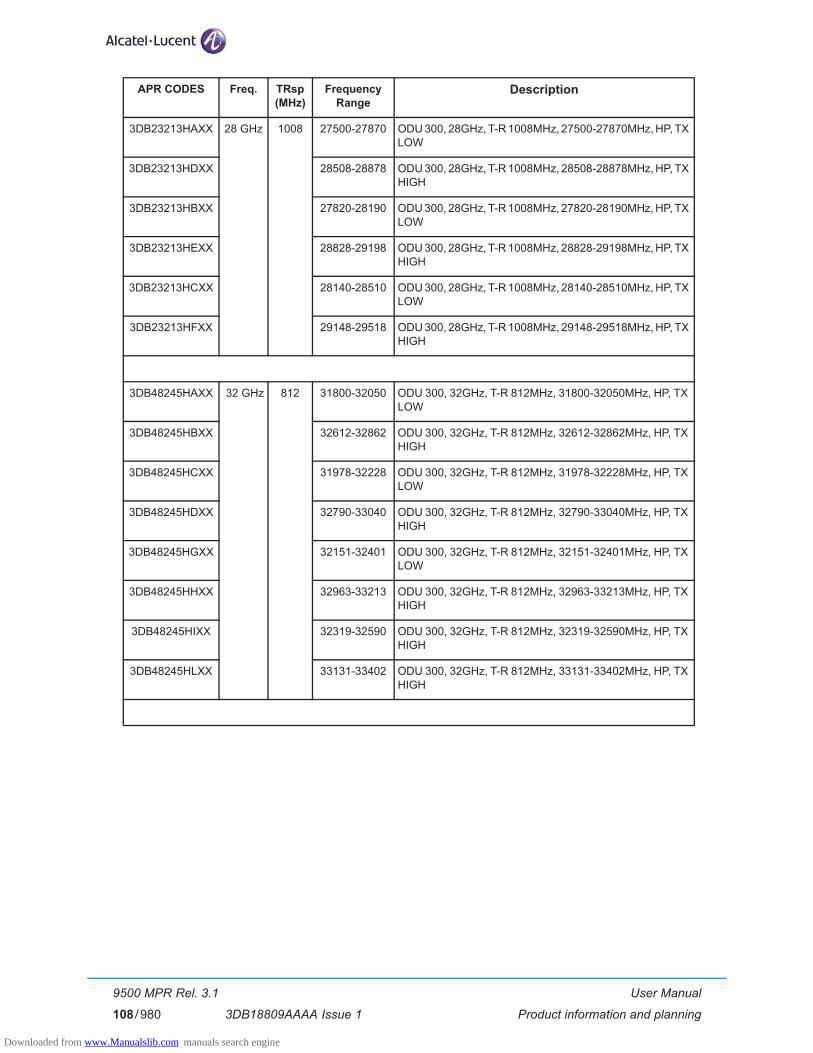
User Manual
Product information and planning
9500 MPR Rel. 3.1
3DB18809AAAA Issue 1108/980
3DB23213HAXX 28 GHz 1008 27500-27870 ODU 300, 28GHz, T-R 1008MHz, 27500-27870MHz, HP, TX LOW
3DB23213HDXX 28508-28878 ODU 300, 28GHz, T-R 1008MHz, 28508-28878MHz, HP, TX HIGH
3DB23213HBXX 27820-28190 ODU 300, 28GHz, T-R 1008MHz, 27820-28190MHz, HP, TX LOW
3DB23213HEXX 28828-29198 ODU 300, 28GHz, T-R 1008MHz, 28828-29198MHz, HP, TX HIGH
3DB23213HCXX 28140-28510 ODU 300, 28GHz, T-R 1008MHz, 28140-28510MHz, HP, TX LOW
3DB23213HFXX 29148-29518 ODU 300, 28GHz, T-R 1008MHz, 29148-29518MHz, HP, TX HIGH
3DB48245HAXX 32 GHz 812 31800-32050 ODU 300, 32GHz, T-R 812MHz, 31800-32050MHz, HP, TX LOW
3DB48245HBXX 32612-32862 ODU 300, 32GHz, T-R 812MHz, 32612-32862MHz, HP, TX HIGH
3DB48245HCXX 31978-32228 ODU 300, 32GHz, T-R 812MHz, 31978-32228MHz, HP, TX LOW
3DB48245HDXX 32790-33040 ODU 300, 32GHz, T-R 812MHz, 32790-33040MHz, HP, TX HIGH
3DB48245HGXX 32151-32401 ODU 300, 32GHz, T-R 812MHz, 32151-32401MHz, HP, TX LOW
3DB48245HHXX 32963-33213 ODU 300, 32GHz, T-R 812MHz, 32963-33213MHz, HP, TX HIGH
3DB48245HIXX 32319-32590 ODU 300, 32GHz, T-R 812MHz, 32319-32590MHz, HP, TX HIGH
3DB48245HLXX 33131-33402 ODU 300, 32GHz, T-R 812MHz, 33131-33402MHz, HP, TX HIGH
APR CODES Freq. TRsp (MHz)
Frequency Range
Description
Downloaded from www.Manualslib.com manuals search engine
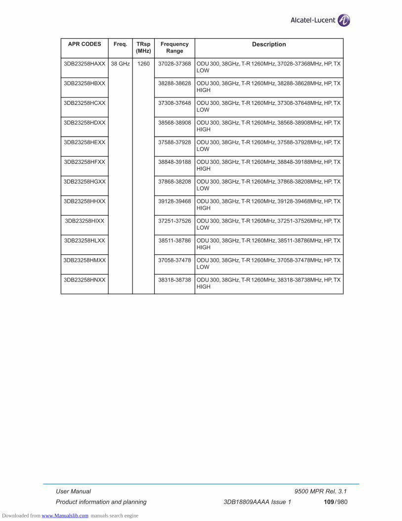
User Manual
Product information and planning
9500 MPR Rel. 3.1
3DB18809AAAA Issue 1 109/980
3DB23258HAXX 38 GHz 1260 37028-37368 ODU 300, 38GHz, T-R 1260MHz, 37028-37368MHz, HP, TX LOW
3DB23258HBXX 38288-38628 ODU 300, 38GHz, T-R 1260MHz, 38288-38628MHz, HP, TX HIGH
3DB23258HCXX 37308-37648 ODU 300, 38GHz, T-R 1260MHz, 37308-37648MHz, HP, TX LOW
3DB23258HDXX 38568-38908 ODU 300, 38GHz, T-R 1260MHz, 38568-38908MHz, HP, TX HIGH
3DB23258HEXX 37588-37928 ODU 300, 38GHz, T-R 1260MHz, 37588-37928MHz, HP, TX LOW
3DB23258HFXX 38848-39188 ODU 300, 38GHz, T-R 1260MHz, 38848-39188MHz, HP, TX HIGH
3DB23258HGXX 37868-38208 ODU 300, 38GHz, T-R 1260MHz, 37868-38208MHz, HP, TX LOW
3DB23258HHXX 39128-39468 ODU 300, 38GHz, T-R 1260MHz, 39128-39468MHz, HP, TX HIGH
3DB23258HIXX 37251-37526 ODU 300, 38GHz, T-R 1260MHz, 37251-37526MHz, HP, TX LOW
3DB23258HLXX 38511-38786 ODU 300, 38GHz, T-R 1260MHz, 38511-38786MHz, HP, TX HIGH
3DB23258HMXX 37058-37478 ODU 300, 38GHz, T-R 1260MHz, 37058-37478MHz, HP, TX LOW
3DB23258HNXX 38318-38738 ODU 300, 38GHz, T-R 1260MHz, 38318-38738MHz, HP, TX HIGH
APR CODES Freq. TRsp (MHz)
Frequency Range
Description
Downloaded from www.Manualslib.com manuals search engine

User Manual
Product information and planning
9500 MPR Rel. 3.1
3DB18809AAAA Issue 1110/980
2.7.3 MPT-HC with internal diplexer
Table 11. MPT-HC codes with internal diplexer
Band (GHz) Shifter (MHz) Tx sub-band APR codes Tx frequency (MHz)
L6 252 1 3DB20441ABXX 5930-6049
1P 3DB20443ABXX 6182-6302
2 3DB20442ABXX 6048-6168
2P 3DB20444ABXX 6301-6420
U6 340 1 3DB20437ABXX 6420-6600
1P 3DB20439ABXX 6760-6940
2 3DB20438ABXX 6565-6745
2P 3DB20440ABXX 6905-7085
3 3DB20464ABXX 6595-6775
3P 3DB20465ABXX 6935-7115
11 530-490 1 3DB20371ABXX 10695-10955
1P 3DB20547ABXX 11205-11485
2 3DB20546ABXX 10935-11205
2P 3DB20548ABXX 11445-11705
13 266 1 3DB20372ABXX 12750-12865
1P 3DB20420ABXX 13016-13131
2 3DB20419ABXX 12861-12980
2P 3DB20421ABXX 13127-13246
15 308-315-322 1 3DB20466ABXX 14630-14766
1P 3DB20468ABXX 14945-15081
2 3DB20467ABXX 14759-14899
2P 3DB20469ABXX 15074-15215
420-475 1 3DB20373ABXX 14500-14724
1P 3DB20423ABXX 14920-15144
420 2 3DB20422ABXX 14710-14941
2P 3DB20424ABXX 15130-15361
490 1 3DB20425ABXX 14400-14635
1P 3DB20427ABXX 14890-15125
2 3DB20426ABXX 14625-14860
2P 3DB20428ABXX 15115-15350
640-644-728 1 3DB20448ABXX 14500-14700
1P 3DB20449ABXX 15144-15348
Downloaded from www.Manualslib.com manuals search engine

User Manual
Product information and planning
9500 MPR Rel. 3.1
3DB18809AAAA Issue 1 111/980
18 1560 1 3DB20432ABXX 17700-18140
1P 3DB20433ABXX 19260-19700
340 1 3DB20549ABXX 18581-18700
1P 3DB20551ABXX 18920-19040
2 3DB20550ABXX 18701-18820
2P 3DB20552ABXX 19040-19160
1008-1010 1 3DB20374ABXX 17700-18201
1P 3DB20430ABXX 18710-19211
2 3DB20429ABXX 18180-18690
2P 3DB20431ABXX 19190-19700
23 1200-1232 1 3DB20473ABXX 21198-21819
1P 3DB20475ABXX 22400-23019
1050-1200-1232 2 3DB20474ABXX 21781-22400
2P 3DB20476ABXX 22981-23600
1008 1 3DB20375ABXX 22000-22315
1P 3DB20471ABXX 23008-23323
2 3DB20470ABXX 22300-22600
2P 3DB20472ABXX 23308-23608
25 1008 1 3DB20376ABXX 24540-24997
1P 3DB20554ABXX 25548-26005
2 3DB20553ABXX 24994-25448
2P 3DB20555ABXX 26002-26456
38 1260 1 3DB20458ABXX 37050-37620
1P 3DB20460ABXX 38310-38880
2 3DB20459ABXX 37619-38180
2P 3DB20461ABXX 38879-39440
Band (GHz) Shifter (MHz) Tx sub-band APR codes Tx frequency (MHz)
Downloaded from www.Manualslib.com manuals search engine

User Manual
Product information and planning
9500 MPR Rel. 3.1
3DB18809AAAA Issue 1112/980
2.7.4 MPT-HC V2 with internal diplexer
Table 12. MPT-HC V2 codes with internal diplexer
Band (GHz) Shifter (MHz) Tx sub-band APR codes Tx frequency (MHz)
L6 252 1 3DB20441BAXX 5930-6049
1P 3DB20443BAXX 6182-6302
2 3DB20442BAXX 6048-6168
2P 3DB20444BAXX 6301-6420
U6 340 1 3DB20437BAXX 6420-6600
1P 3DB20439BAXX 6760-6940
2 3DB20438BAXX 6565-6745
2P 3DB20440BAXX 6905-7085
3 3DB20464BAXX 6595-6775
3P 3DB20465BAXX 6935-7115
11 530-490 1 3DB20371BAXX 10695-10955
1P 3DB20547BAXX 11205-11485
2 3DB20546BAXX 10935-11205
2P 3DB20548BAXX 11445-11705
13 266 1 3DB20372BAXX 12750-12865
1P 3DB20420BAXX 13016-13131
2 3DB20419BAXX 12861-12980
2P 3DB20421BAXX 13127-13246
15 308-315-322 1 3DB20466BAXX 14630-14766
1P 3DB20468BAXX 14945-15081
2 3DB20467BAXX 14759-14899
2P 3DB20469BAXX 15074-15215
420-475 1 3DB20373BAXX 14500-14724
1P 3DB20423BAXX 14920-15144
420 2 3DB20422BAXX 14710-14941
2P 3DB20424BAXX 15130-15361
490 1 3DB20425BAXX 14400-14635
1P 3DB20427BAXX 14890-15125
2 3DB20426BAXX 14625-14860
2P 3DB20428BAXX 15115-15350
640-644-728 1 3DB20448BAXX 14500-14700
1P 3DB20449BAXX 15144-15348
Downloaded from www.Manualslib.com manuals search engine
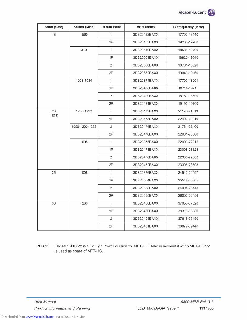
User Manual
Product information and planning
9500 MPR Rel. 3.1
3DB18809AAAA Issue 1 113/980
N.B.1: The MPT-HC V2 is a Tx High Power version vs. MPT-HC. Take in account it when MPT-HC V2�is used as spare of MPT-HC.
18 1560 1 3DB20432BAXX 17700-18140
1P 3DB20433BAXX 19260-19700
340 1 3DB20549BAXX 18581-18700
1P 3DB20551BAXX 18920-19040
2 3DB20550BAXX 18701-18820
2P 3DB20552BAXX 19040-19160
1008-1010 1 3DB20374BAXX 17700-18201
1P 3DB20430BAXX 18710-19211
2 3DB20429BAXX 18180-18690
2P 3DB20431BAXX 19190-19700
23(NB1)
1200-1232 1 3DB20473BAXX 21198-21819
1P 3DB20475BAXX 22400-23019
1050-1200-1232 2 3DB20474BAXX 21781-22400
2P 3DB20476BAXX 22981-23600
1008 1 3DB20375BAXX 22000-22315
1P 3DB20471BAXX 23008-23323
2 3DB20470BAXX 22300-22600
2P 3DB20472BAXX 23308-23608
25 1008 1 3DB20376BAXX 24540-24997
1P 3DB20554BAXX 25548-26005
2 3DB20553BAXX 24994-25448
2P 3DB20555BAXX 26002-26456
38 1260 1 3DB20458BAXX 37050-37620
1P 3DB20460BAXX 38310-38880
2 3DB20459BAXX 37619-38180
2P 3DB20461BAXX 38879-39440
Band (GHz) Shifter (MHz) Tx sub-band APR codes Tx frequency (MHz)
Downloaded from www.Manualslib.com manuals search engine
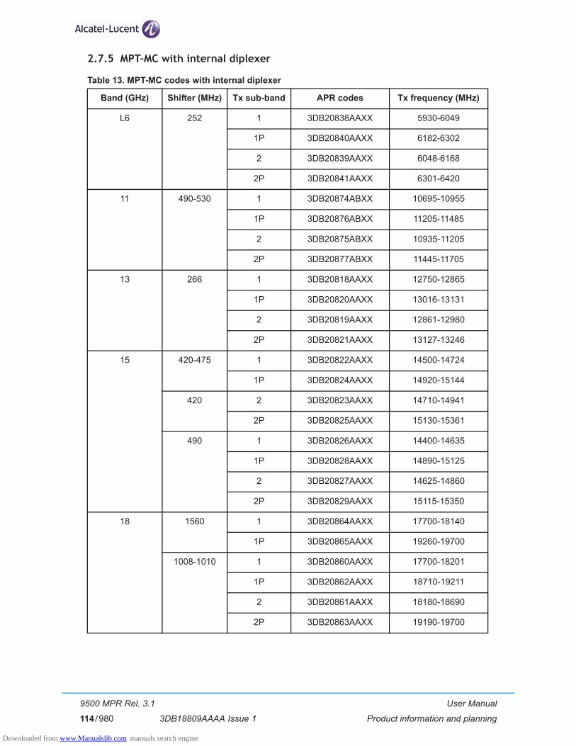
User Manual
Product information and planning
9500 MPR Rel. 3.1
3DB18809AAAA Issue 1114/980
2.7.5 MPT-MC with internal diplexer
Table 13. MPT-MC codes with internal diplexer
Band (GHz) Shifter (MHz) Tx sub-band APR codes Tx frequency (MHz)
L6 252 1 3DB20838AAXX 5930-6049
1P 3DB20840AAXX 6182-6302
2 3DB20839AAXX 6048-6168
2P 3DB20841AAXX 6301-6420
11 490-530 1 3DB20874ABXX 10695-10955
1P 3DB20876ABXX 11205-11485
2 3DB20875ABXX 10935-11205
2P 3DB20877ABXX 11445-11705
13 266 1 3DB20818AAXX 12750-12865
1P 3DB20820AAXX 13016-13131
2 3DB20819AAXX 12861-12980
2P 3DB20821AAXX 13127-13246
15 420-475 1 3DB20822AAXX 14500-14724
1P 3DB20824AAXX 14920-15144
420 2 3DB20823AAXX 14710-14941
2P 3DB20825AAXX 15130-15361
490 1 3DB20826AAXX 14400-14635
1P 3DB20828AAXX 14890-15125
2 3DB20827AAXX 14625-14860
2P 3DB20829AAXX 15115-15350
18 1560 1 3DB20864AAXX 17700-18140
1P 3DB20865AAXX 19260-19700
1008-1010 1 3DB20860AAXX 17700-18201
1P 3DB20862AAXX 18710-19211
2 3DB20861AAXX 18180-18690
2P 3DB20863AAXX 19190-19700
Downloaded from www.Manualslib.com manuals search engine
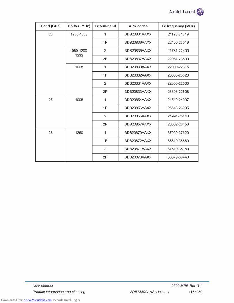
User Manual
Product information and planning
9500 MPR Rel. 3.1
3DB18809AAAA Issue 1 115/980
23 1200-1232 1 3DB20834AAXX 21198-21819
1P 3DB20836AAXX 22400-23019
1050-1200-1232
2 3DB20835AAXX 21781-22400
2P 3DB20837AAXX 22981-23600
1008 1 3DB20830AAXX 22000-22315
1P 3DB20832AAXX 23008-23323
2 3DB20831AAXX 22300-22600
2P 3DB20833AAXX 23308-23608
25 1008 1 3DB20854AAXX 24540-24997
1P 3DB20856AAXX 25548-26005
2 3DB20855AAXX 24994-25448
2P 3DB20857AAXX 26002-26456
38 1260 1 3DB20870AAXX 37050-37620
1P 3DB20872AAXX 38310-38880
2 3DB20871AAXX 37619-38180
2P 3DB20873AAXX 38879-39440
Band (GHz) Shifter (MHz) Tx sub-band APR codes Tx frequency (MHz)
Downloaded from www.Manualslib.com manuals search engine

User Manual
Product information and planning
9500 MPR Rel. 3.1
3DB18809AAAA Issue 1116/980
2.7.6 Part lists of MPT-HC/MPT-HC V2/MPT-MC with external diplexer
The diplexer included in the available BRANCHING assemblies refers to ITU–R F.385, 386 and RF special CUSTOMERS channelling with Tx/Rx separation specified in following Table 18. and Table 23. Each diplexer is a 3-port passive device with two band–pass filters as described hereafter.
Each BRANCHING assembly has two different variants by duplex spacing, depending on the RF_Tx out-put frequency band as described on the table below:
The arrangement between each filters on the same branching device is described below:
WARNING: f1, f2, f3 and f4 frequencies of the branching filters refer to the extreme channel frequencies and not to the cut–off frequencies of the filters.
Table 14. 7 GHz MPT-MC codes with external diplexer
Table 15. 7 GHz MPT-HC codes with external diplexer
3DB Variant Channel
3DB xxxxx AAXX 1_1p
3DB xxxxx ABXX 2_2p
Band (GHz) Shifter (MHz) Tx sub-band APR codes Tx frequency (MHz)
7/8 NA Lower 3DB20858AAXX 7107 - 8370
Upper 3DB20859AAXX 7261 - 8496
Band (GHz) Shifter (MHz) Tx sub-band APR codes Tx frequency (MHz)
7/8 NA Lower 3DB20454ADXX 7107 - 8370
Upper 3DB20456ADXX 7261 - 8496
Downloaded from www.Manualslib.com manuals search engine
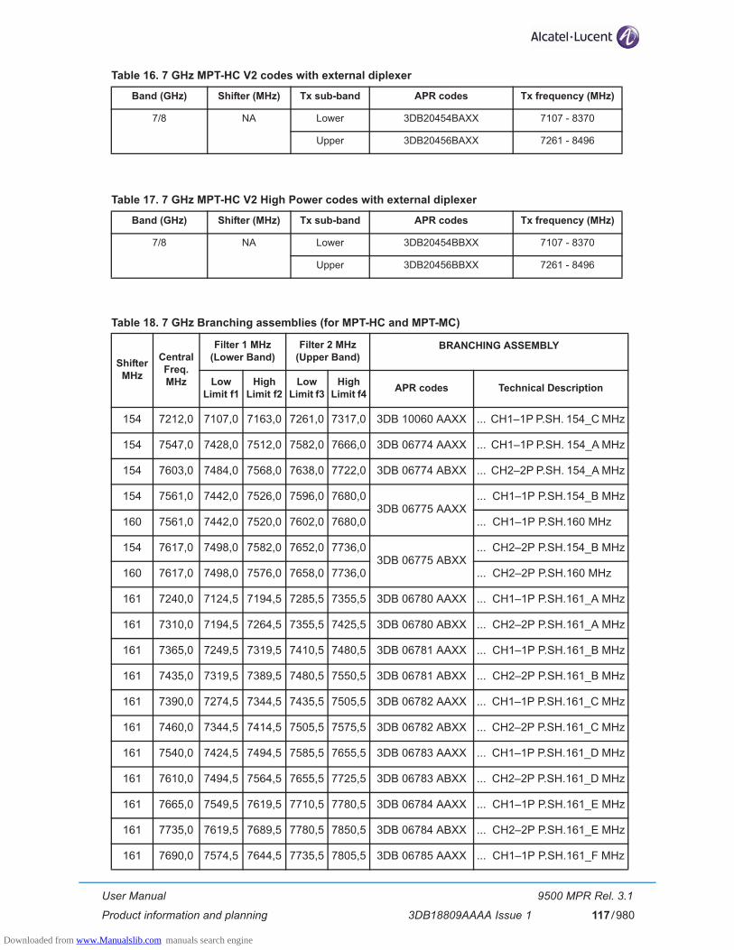
User Manual
Product information and planning
9500 MPR Rel. 3.1
3DB18809AAAA Issue 1 117/980
Table 16. 7 GHz MPT-HC V2 codes with external diplexer
Table 17. 7 GHz MPT-HC V2 High Power codes with external diplexer
Table 18. 7 GHz Branching assemblies (for MPT-HC and MPT-MC)
Band (GHz) Shifter (MHz) Tx sub-band APR codes Tx frequency (MHz)
7/8 NA Lower 3DB20454BAXX 7107 - 8370
Upper 3DB20456BAXX 7261 - 8496
Band (GHz) Shifter (MHz) Tx sub-band APR codes Tx frequency (MHz)
7/8 NA Lower 3DB20454BBXX 7107 - 8370
Upper 3DB20456BBXX 7261 - 8496
Shifter MHz
Central Freq. MHz
Filter 1 MHz (Lower Band)
Filter 2 MHz(Upper Band)
BRANCHING ASSEMBLY
Low Limit f1
High Limit f2
Low Limit f3
High Limit f4 APR codes Technical Description
154 7212,0 7107,0 7163,0 7261,0 7317,0 3DB 10060 AAXX ... CH1–1P P.SH. 154_C MHz
154 7547,0 7428,0 7512,0 7582,0 7666,0 3DB 06774 AAXX ... CH1–1P P.SH. 154_A MHz
154 7603,0 7484,0 7568,0 7638,0 7722,0 3DB 06774 ABXX ... CH2–2P P.SH. 154_A MHz
154 7561,0 7442,0 7526,0 7596,0 7680,03DB 06775 AAXX
... CH1–1P P.SH.154_B MHz
160 7561,0 7442,0 7520,0 7602,0 7680,0 ... CH1–1P P.SH.160 MHz
154 7617,0 7498,0 7582,0 7652,0 7736,03DB 06775 ABXX
... CH2–2P P.SH.154_B MHz
160 7617,0 7498,0 7576,0 7658,0 7736,0 ... CH2–2P P.SH.160 MHz
161 7240,0 7124,5 7194,5 7285,5 7355,5 3DB 06780 AAXX ... CH1–1P P.SH.161_A MHz
161 7310,0 7194,5 7264,5 7355,5 7425,5 3DB 06780 ABXX ... CH2–2P P.SH.161_A MHz
161 7365,0 7249,5 7319,5 7410,5 7480,5 3DB 06781 AAXX ... CH1–1P P.SH.161_B MHz
161 7435,0 7319,5 7389,5 7480,5 7550,5 3DB 06781 ABXX ... CH2–2P P.SH.161_B MHz
161 7390,0 7274,5 7344,5 7435,5 7505,5 3DB 06782 AAXX ... CH1–1P P.SH.161_C MHz
161 7460,0 7344,5 7414,5 7505,5 7575,5 3DB 06782 ABXX ... CH2–2P P.SH.161_C MHz
161 7540,0 7424,5 7494,5 7585,5 7655,5 3DB 06783 AAXX ... CH1–1P P.SH.161_D MHz
161 7610,0 7494,5 7564,5 7655,5 7725,5 3DB 06783 ABXX ... CH2–2P P.SH.161_D MHz
161 7665,0 7549,5 7619,5 7710,5 7780,5 3DB 06784 AAXX ... CH1–1P P.SH.161_E MHz
161 7735,0 7619,5 7689,5 7780,5 7850,5 3DB 06784 ABXX ... CH2–2P P.SH.161_E MHz
161 7690,0 7574,5 7644,5 7735,5 7805,5 3DB 06785 AAXX ... CH1–1P P.SH.161_F MHz
Downloaded from www.Manualslib.com manuals search engine
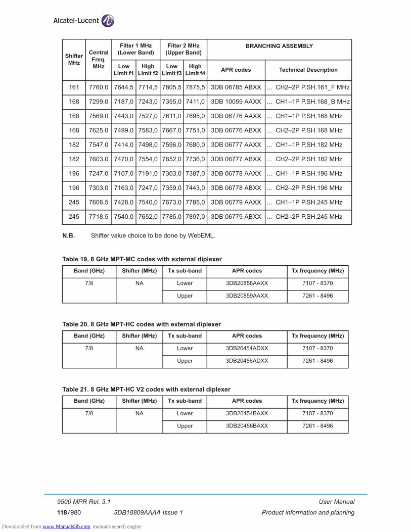
User Manual
Product information and planning
9500 MPR Rel. 3.1
3DB18809AAAA Issue 1118/980
N.B. Shifter value choice to be done by WebEML.
Table 19. 8 GHz MPT-MC codes with external diplexer
Table 20. 8 GHz MPT-HC codes with external diplexer
Table 21. 8 GHz MPT-HC V2 codes with external diplexer
161 7760,0 7644,5 7714,5 7805,5 7875,5 3DB 06785 ABXX ... CH2–2P P.SH.161_F MHz
168 7299,0 7187,0 7243,0 7355,0 7411,0 3DB 10059 AAXX ... CH1–1P P.SH.168_B MHz
168 7569,0 7443,0 7527,0 7611,0 7695,0 3DB 06776 AAXX ... CH1–1P P.SH.168 MHz
168 7625,0 7499,0 7583,0 7667,0 7751,0 3DB 06776 ABXX ... CH2–2P P.SH.168 MHz
182 7547,0 7414,0 7498,0 7596,0 7680,0 3DB 06777 AAXX ... CH1–1P P.SH.182 MHz
182 7603,0 7470,0 7554,0 7652,0 7736,0 3DB 06777 ABXX ... CH2–2P P.SH.182 MHz
196 7247,0 7107,0 7191,0 7303,0 7387,0 3DB 06778 AAXX ... CH1–1P P.SH.196 MHz
196 7303,0 7163,0 7247,0 7359,0 7443,0 3DB 06778 ABXX ... CH2–2P P.SH.196 MHz
245 7606,5 7428,0 7540,0 7673,0 7785,0 3DB 06779 AAXX ... CH1–1P P.SH.245 MHz
245 7718,5 7540,0 7652,0 7785,0 7897,0 3DB 06779 ABXX ... CH2–2P P.SH.245 MHz
Band (GHz) Shifter (MHz) Tx sub-band APR codes Tx frequency (MHz)
7/8 NA Lower 3DB20858AAXX 7107 - 8370
Upper 3DB20859AAXX 7261 - 8496
Band (GHz) Shifter (MHz) Tx sub-band APR codes Tx frequency (MHz)
7/8 NA Lower 3DB20454ADXX 7107 - 8370
Upper 3DB20456ADXX 7261 - 8496
Band (GHz) Shifter (MHz) Tx sub-band APR codes Tx frequency (MHz)
7/8 NA Lower 3DB20454BAXX 7107 - 8370
Upper 3DB20456BAXX 7261 - 8496
Shifter MHz
Central Freq. MHz
Filter 1 MHz (Lower Band)
Filter 2 MHz(Upper Band)
BRANCHING ASSEMBLY
Low Limit f1
High Limit f2
Low Limit f3
High Limit f4 APR codes Technical Description
Downloaded from www.Manualslib.com manuals search engine

User Manual
Product information and planning
9500 MPR Rel. 3.1
3DB18809AAAA Issue 1 119/980
Table 22. 8 GHz MPT-HC V2 High Power codes with external diplexer
Table 23. 8 GHz Branching assemblies (for MPT-HC and MPT-MC)
2.7.7 MPT-HC optical interface (mandatory for 1+1 configuration)
Table 24. MPT-HC optical interface (mandatory for 1+1 configuration)
Band (GHz) Shifter (MHz) Tx sub-band APR codes Tx frequency (MHz)
7/8 NA Lower 3DB20454BBXX 7107 - 8370
Upper 3DB20456BBXX 7261 - 8496
Shifter MHz
Central Freq. MHz
Filter 1 MHz (Lower Band)
Filter 2 MHz(Upper Band)
BRANCHING ASSEMBLY
Low Limit f1
High Limit f2
Low Limit f3
High Limit f4 APR codes Technical Description
119 8366.5 8286.0 8328.0 8405.0 8447.03DB 06789 AAXX
... CH1–1P P.SH.119 MHz
126 8366.5 8282.5 8324.5 8408.5 8450.5 ... CH1–1P P.SH.126 MHz
119 8408.5 8328.0 8370.0 8447.0 8489.03DB 06789 ABXX
... CH2–2P P.SH.119 MHz
126 8408.5 8324.5 8366.5 8450.5 8492.5 ... CH2–2P P.SH.126 MHz
151.614 8315.010 8204.217 8274.189 8355.831 8425.803 3DB 06787 AAXX ... CH1–1P P.SH.151 MHz
151.614 8384.982 8274.189 8344.161 8425.803 8495.775 3DB 06787 ABXX ... CH2–2P P.SH.151 MHz
208 8217.0 8064.0 8162.0 8272.0 8370.0 3DB 10073 AAXX ... CH1–1P P.SH.208 MHZ
208 8301.0 8148.0 8246.0 8356.0 8454.0 3DB 10073 ABXX ... CH2–2P P.SH.208 MHZ
266 8097.5 7905.0 8024.0 8171.0 8290.0 3DB 06788 AAXX ... CH1–1P P.SH.266 MHZ
266 8209.5 8017.0 8136.0 8283.0 8402.0 3DB 06788 ABXX ... CH2–2P P.SH.266 MHZ
294.440
7947.835
7749.755
7851.475 8044.195
8145.915
3DB 06786 AAXX ... CH1–1PP.SH.294/305/311 MHZ305.560 7738.635 8157.035
311.320 7732.875 8162.795
311.320 8066.435 7851.475
7970.075
8162.795 8281.395
3DB 06786 ABXX ... CH2–2PP.SH.294/305/311 MHZ294.440
8063.7407862.965
8157.4058264.515
305.560 7851.845 8275.635
213.5 8147.0 8035.0 8046.0 8248.0 8259.0 3DB 10103 AAXX ... CH1–1P P.SH. 213.5 MHZ
Description APR Codes Remarks
SFP 1000Base-Sx Transceiver 1AB383760001 Optical SFP module to be installed optionally in the MPT-HC to provide the optical interface
SFP 1000Base-Lx Transceiver 1AB187280040
Downloaded from www.Manualslib.com manuals search engine
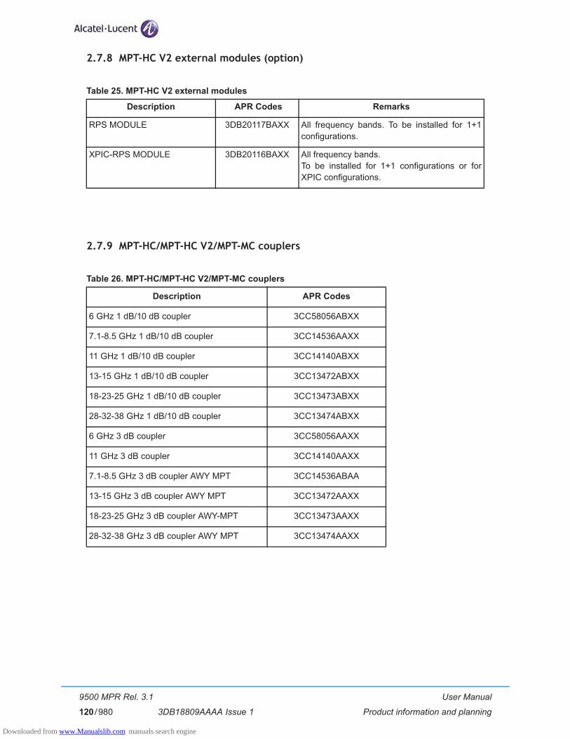
User Manual
Product information and planning
9500 MPR Rel. 3.1
3DB18809AAAA Issue 1120/980
2.7.8 MPT-HC V2 external modules (option)
Table 25. MPT-HC V2 external modules
2.7.9 MPT-HC/MPT-HC V2/MPT-MC couplers
Table 26. MPT-HC/MPT-HC V2/MPT-MC couplers
Description APR Codes Remarks
RPS MODULE 3DB20117BAXX All frequency bands. To be installed for 1+1 configurations.
XPIC-RPS MODULE 3DB20116BAXX All frequency bands. To be installed for 1+1 configurations or for XPIC configurations.
Description APR Codes
6 GHz 1 dB/10 dB coupler 3CC58056ABXX
7.1-8.5 GHz 1 dB/10 dB coupler 3CC14536AAXX
11 GHz 1 dB/10 dB coupler 3CC14140ABXX
13-15 GHz 1 dB/10 dB coupler 3CC13472ABXX
18-23-25 GHz 1 dB/10 dB coupler 3CC13473ABXX
28-32-38 GHz 1 dB/10 dB coupler 3CC13474ABXX
6 GHz 3 dB coupler 3CC58056AAXX
11 GHz 3 dB coupler 3CC14140AAXX
7.1-8.5 GHz 3 dB coupler AWY MPT 3CC14536ABAA
13-15 GHz 3 dB coupler AWY MPT 3CC13472AAXX
18-23-25 GHz 3 dB coupler AWY-MPT 3CC13473AAXX
28-32-38 GHz 3 dB coupler AWY MPT 3CC13474AAXX
Downloaded from www.Manualslib.com manuals search engine
User Manual
Product information and planning
9500 MPR Rel. 3.1
3DB18809AAAA Issue 1 121/980
2.8 Functional description
2.8.1 MSS (Indoor Unit)
The MSS incorporates the base–band processing and also modem functionalities only when ODU300 is connected. MSS offers tributaries interfaces as well as supervision. The MSS is frequency–independent.
Two MSS are available:
– MSS-8
– MSS-4
The MSS-8 is made of:
– 1 subrack (MSS-8 shelf)
– 1 or 2 Core-E Modules (Working & Spare)
– up to 6 Transport Modules
– 1 AUX Peripheral Module (option: to be installed in Transport slot #8)
– 1 +24 Vdc/-48 Vdc Converter Module (option for +24 Vdc office application: to be installed in Transport slot #4, #6 or #8)
– 1 Fans unit
The MSS-4 is made of:
– 1 subrack (MSS-4 shelf)
– 1 or 2 Core-E Modules (Working & Spare)
– up to 2 Transport Modules
– 1 AUX Peripheral Module (option: to be installed in Transport slot #4)
– 1 +24 Vdc/-48 Vdc Converter Module (option for +24 Vdc office application: to be installed in Transport slot #3 or #4)
– 1 Fans unit
There are six types of Transport Modules:
– 32xE1 Local Access Module
– 16xE1 ATM Local Access - ASAP Module
– 2xSTM-1 Local Access Module
– Modem Module: to interface the ODU300
– MPT Access Module: to interface up to two MPT. It can provide the PFoE
– EAS Module: provides the access of up to 8 Ethernet traffic interfaces.
In the right part of the MSS shelf there are two sub-D 2-pole power supply connectors.
Downloaded from www.Manualslib.com manuals search engine

User Manual
Product information and planning
9500 MPR Rel. 3.1
3DB18809AAAA Issue 1122/980
2.8.1.1 Power distribution
The system receives the Battery input through 2 power connectors mounted on the Subrack structure and connected directly to the Backplane.
Each board, in which a DC/DC converter is mounted, is provided with fuses and diodes on all the lines, in order to be fully independent from the other ones.
The ODU300 Modem unit provides the power supply to the ODU300.
The MPT Access unit can provide the PFoE to MPT to supply the MPT by using the same cable used also to carry the Ethernet traffic.
On the output section the Core-E (Main) board provides +3.3V in parallel with the Core-E (Spare) board to supply the Fan Unit.
A 3.3V, coming from the two Core-E units, is provided to read the EEPROM present on each board also when the DC/DC converter, present on its board, is out of order.
Figure 39. Power Distribution Architecture
Batt. A-48 Vdc +15%/-20%
Core-E(Spare)
32E1/ASAP/STM-1
MPTAccess
ODU300MODEM
FAN UNIT
BACK PLANE
Batt. B-48 Vdc +15%/-20%
Core-E(MAIN)
Downloaded from www.Manualslib.com manuals search engine

User Manual
Product information and planning
9500 MPR Rel. 3.1
3DB18809AAAA Issue 1 123/980
2.8.1.2 +24 Vdc/-48 Vdc Converter unit
When office power configuration consists of +24 Vdc a +24/-48 volt power converter is required to con-dition office power to -48 Vdc for the MSS-4/8 shelf.
The power converter resides in slot 3 or 4 of the MSS-4 shelf and either slot 4, 6, or 8 in the MSS-8 shelf.
Office power (+24 Vdc) is connected to the PDU which in turn connects to the power converter.
The output of the Power Converter (-48 Vdc) is then connected to the MSS-4/8 shelf power connector(s).
The Power Converter supports both unprotected and protected power arrangements.
The same PDU power cables are used to connect between the PDU and the power converter.
Keyed power cables are used to connect between the power converter and the MSS-4/8 shelf.
Figure 40. +24 Vdc/-48 Vdc Converter unit
Downloaded from www.Manualslib.com manuals search engine
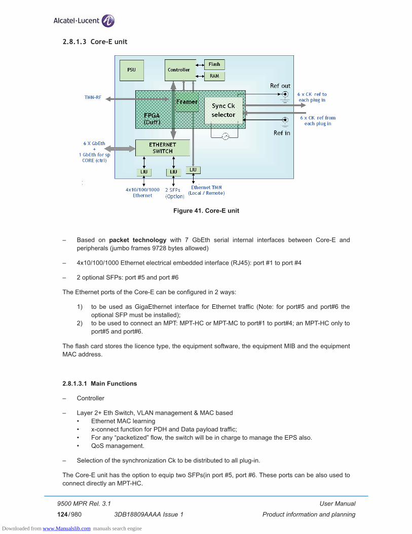
User Manual
Product information and planning
9500 MPR Rel. 3.1
3DB18809AAAA Issue 1124/980
2.8.1.3 Core-E unit
Figure 41. Core-E unit
– Based on packet technology with 7 GbEth serial internal interfaces between Core-E and peripherals (jumbo frames 9728 bytes allowed)
– 4x10/100/1000 Ethernet electrical embedded interface (RJ45): port #1 to port #4
– 2 optional SFPs: port #5 and port #6
The Ethernet ports of the Core-E can be configured in 2 ways:
1) to be used as GigaEthernet interface for Ethernet traffic (Note: for port#5 and port#6 the optional SFP must be installed);
2) to be used to connect an MPT: MPT-HC or MPT-MC to port#1 to port#4; an MPT-HC only to port#5 and port#6.
The flash card stores the licence type, the equipment software, the equipment MIB and the equipment MAC address.
2.8.1.3.1 Main Functions
– Controller
– Layer 2+ Eth Switch, VLAN management & MAC based• Ethernet MAC learning • x-connect function for PDH and Data payload traffic;• For any “packetized” flow, the switch will be in charge to manage the EPS also.• QoS management.
– Selection of the synchronization Ck to be distributed to all plug-in.
The Core-E unit has the option to equip two SFPs(in port #5, port #6. These ports can be also used to connect directly an MPT-HC.
Downloaded from www.Manualslib.com manuals search engine

User Manual
Product information and planning
9500 MPR Rel. 3.1
3DB18809AAAA Issue 1 125/980
2.8.1.3.2 Available SFPs for port #5 and port #6
The following SFPs are available:
– 1000BASE-LX (optical interface for Ethernet traffic)
– 1000BASE-SX (optical interface for Ethernet traffic)
– 1000BASE-T (electrical interface for Ethernet traffic)
– 2xE1 (electrical interface for 2 E1 streams)
– EoSDH (optical interface for STM-1 signal with Ethernet traffic encapsulation)
2.8.1.3.2.1 2xE1 SFP
The 2xE1 SFP is an SFP module supporting MEF8 circuit emulation of up to 2 E1.
This module supports:
– differential clock recovery
– node timing
– loop timing
This module is Synchronous Ethernet capable and it is compliant to optical SFP 1000BASE-X. It can deliver the clock recovered from one of two tributaries to hosting card through the standard SFP pin-out.
SFP module supports TDM2TDM and TDM2ETH services.
The port, in which the SFP has been installed, must be enabled by the WebEML as an optical port, then all the configuration must be done with an Enhanced Configuration File.
Note: The SFP must be installed after the Configuration File has been downloaded. If the SFP has�been installed before, remove it and then plug it again.
2.8.1.3.2.2 EoSDH SFP
The Ethernet over SDH SFP is an SFP module supporting the delivery of Ethernet traffic over SDH layer by GFP encapsulation.
The module is compliant to 1000BASE-X specification and support one STM1 interface.
The NE manages the EoSDH SFP as an optical User Ethernet interface. Synchronous operation mode and SSM support are not available, when EoSDH SFP is hosted as optical User Ethernet interface.
Note: For the correct operation of the EoSDH SFP it is necessary to disable the autonegotiation via �WebEML or via the Configuration File (refer to paragraph 4.2 of the Configuration File User�Manual).
Downloaded from www.Manualslib.com manuals search engine

User Manual
Product information and planning
9500 MPR Rel. 3.1
3DB18809AAAA Issue 1126/980
Figure 42. Core-E unit
Warning: The optional optical SFP plug-in, which has to be installed in port #5 and port #6 of the Core-E unit, contains a Class 1 laser source. The laser source is placed in the left side of the SFP plug-in.According to the IEC 60825-1 the explanatory label is not sticked on the equipment due to the lack of space.
2.8.1.4 32xE1 Local Access unit
Figure 43. 32xE1 Local Access unit
In the TX direction, the E1 PDH card (E1 Access) processes and encapsulates up to 32 E1 input lines into an Ethernet packet that is sent to the Core-E card(s).
In the RX direction, the E1 Access card extracts data from the Ethernet data packets and processes the data to provide up to 32 E1 output lines.
CES32 E1 LIUs
wk core
sp core
wk core
sp core
FPGA(Ceres)
Downloaded from www.Manualslib.com manuals search engine
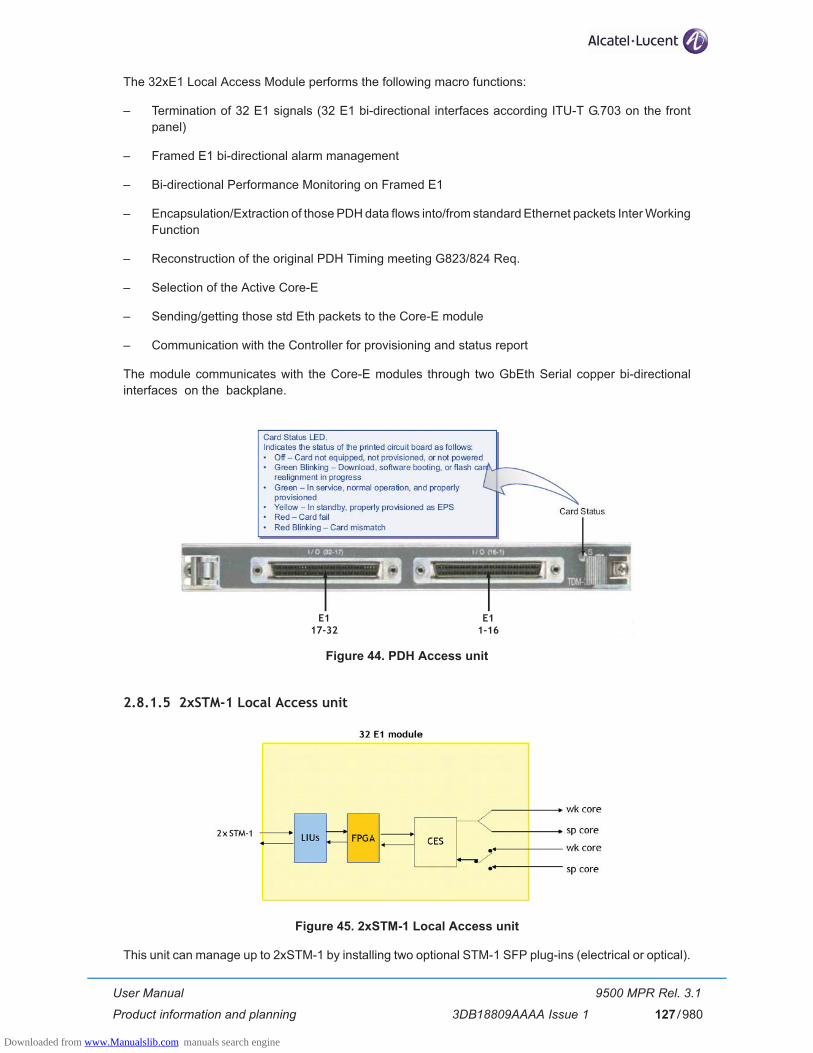
User Manual
Product information and planning
9500 MPR Rel. 3.1
3DB18809AAAA Issue 1 127/980
The 32xE1 Local Access Module performs the following macro functions:
– Termination of 32 E1 signals (32 E1 bi-directional interfaces according ITU-T G.703 on the front panel)
– Framed E1 bi-directional alarm management
– Bi-directional Performance Monitoring on Framed E1
– Encapsulation/Extraction of those PDH data flows into/from standard Ethernet packets Inter Working Function
– Reconstruction of the original PDH Timing meeting G823/824 Req.
– Selection of the Active Core-E
– Sending/getting those std Eth packets to the Core-E module
– Communication with the Controller for provisioning and status report
The module communicates with the Core-E modules through two GbEth Serial copper bi-directional interfaces on the backplane.
Figure 44. PDH Access unit
2.8.1.5 2xSTM-1 Local Access unit
Figure 45. 2xSTM-1 Local Access unit
This unit can manage up to 2xSTM-1 by installing two optional STM-1 SFP plug-ins (electrical or optical).
E117-32
E11-16
Downloaded from www.Manualslib.com manuals search engine

User Manual
Product information and planning
9500 MPR Rel. 3.1
3DB18809AAAA Issue 1128/980
The STM-1 unit can be used in two different working modes, addressing two different network scenarios:
– STM-1 channelized – STM-1 transparent
The STM-1 channelized mode is available by provision the unit as "SDHCHAN" and the STM-1 transparent mode is available by provision the unit as "SDHACC".
The STM-1 unit can support 1 channelized STM-1 or up to 2 transparent STM-1 interfaces.
The STM-1 channelized interface works as a terminal multiplexer; it terminates or originates the SDH frame. It multiplexes NxE1 into an STM-1 electrical/optical line connection. The clock source can be “Loop time” or “Node time”. Typical application is a direct connection to SDH add-drop multiplexers (ADMs). STM-1 card manages one 155 Mbit/s STM1 interface and up to 63xE1. Standard VC4 mapping of lower-order E1 traffic streams to/from STM-1 is applied, that means that a VC4 directly maps up to 63xVC12 into an STM-1 signal (in turn each VC12 contains 1xE1).
Link options include:
– 1+0 non-protected operation – 1+1 EPS protection (available ONLY with the optical interface)
When the protection of the unit is required (1+1 EPS protection), two STM-1 units must be installed.
Clock source from the incoming STM-1 signal can be selected as Network Element source clock. In the event the clock source is lost, clocking falls back to the internal clock or to other of any synch in options.
In the Tx direction, the STM-1 Local Access unit processes and encapsulates up to 2xSTM-1 input lines into an Ethernet packet that is sent to the Core-E card(s).
In the Rx direction, the STM-1 Local Access unit extracts data from the Ethernet data packets and processes the data to provide up to 2 STM-1 output lines.
The 2xSTM-1 Local Access Unit performs the following macro functions:
– Transparent or channelized transport of the STM-1– Encapsulation/Extraction of the STM-1 into/from standard Ethernet packets Inter Working Function– Reconstruction of the original STM-1 Timing– Selection of the Active Core-E– Sending/getting those std Eth packets to the Core-E module– Communication with the Controller for provisioning and status report
The unit communicates with the Core-E modules through two GbEth Serial copper bi-directional interfaces on the backplane.
Figure 46. STM-1 Access unit
Optional SFP (electrical or optical)
Downloaded from www.Manualslib.com manuals search engine
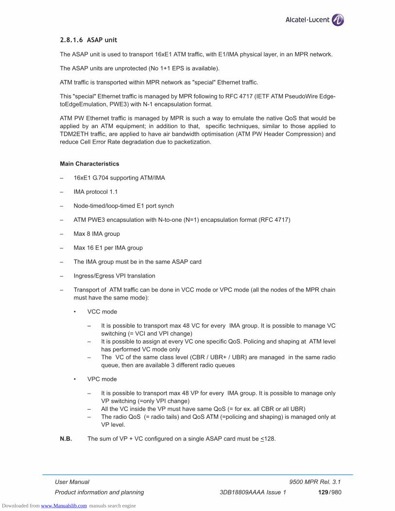
User Manual
Product information and planning
9500 MPR Rel. 3.1
3DB18809AAAA Issue 1 129/980
2.8.1.6 ASAP unit
The ASAP unit is used to transport 16xE1 ATM traffic, with E1/IMA physical layer, in an MPR network.
The ASAP units are unprotected (No 1+1 EPS is available).
ATM traffic is transported within MPR network as "special" Ethernet traffic.
This "special" Ethernet traffic is managed by MPR following to RFC 4717 (IETF ATM PseudoWire Edge-toEdgeEmulation, PWE3) with N-1 encapsulation format.
ATM PW Ethernet traffic is managed by MPR is such a way to emulate the native QoS that would be applied by an ATM equipment; in addition to that, specific techniques, similar to those applied to TDM2ETH traffic, are applied to have air bandwidth optimisation (ATM PW Header Compression) and reduce Cell Error Rate degradation due to packetization.
Main Characteristics
– 16xE1 G.704 supporting ATM/IMA
– IMA protocol 1.1
– Node-timed/loop-timed E1 port synch
– ATM PWE3 encapsulation with N-to-one (N=1) encapsulation format (RFC 4717)
– Max 8 IMA group
– Max 16 E1 per IMA group
– The IMA group must be in the same ASAP card
– Ingress/Egress VPI translation
– Transport of ATM traffic can be done in VCC mode or VPC mode (all the nodes of the MPR chain must have the same mode):
• VCC mode
– It is possible to transport max 48 VC for every IMA group. It is possible to manage VC switching (= VCI and VPI change)
– It is possible to assign at every VC one specific QoS. Policing and shaping at ATM level has performed VC mode only
– The VC of the same class level (CBR / UBR+ / UBR) are managed in the same radio queue, then are available 3 different radio queues
• VPC mode
– It is possible to transport max 48 VP for every IMA group. It is possible to manage only VP switching (=only VPI change)
– All the VC inside the VP must have same QoS (= for ex. all CBR or all UBR)– The radio QoS (= radio tails) and QoS ATM (=policing and shaping) is managed only at
VP level.
N.B. The sum of VP + VC configured on a single ASAP card must be <128.
Downloaded from www.Manualslib.com manuals search engine

User Manual
Product information and planning
9500 MPR Rel. 3.1
3DB18809AAAA Issue 1130/980
Interfaces
– 16 E1 G.704 - SCSI Connectors– 75 ohm or 120 ohm (at NE level)
Block Diagram
(Refer to Figure 47. on page 130).
The 16xE1 ATM streams enter the ASAP unit on the front panel.
The block diagram is divided in 3 parts:
– LIU/Framer– Network Processor– Confederation FPGA
The main functions implemented by the LIU/Framer are:
– Internal termination supported: 75 ohm, 120 ohm.– Line code supported: HDB3.– Pulse shape: digitally programmable – Framing to G.704 E1 signals and to CRC-4 multi-frame alignment signals.– Detection of alarm conditions as loss of signal, loss of frame, loss of signaling multi-frame and loss
of CRC multi-frame.
The Network Processor is the heart of the ASAP card and provides the implementation of the protocols to be supported as well as data forwarding. ATM-IMA over PseudoWire, SAToP (like on the PDH card), CESoP, ML-PPP can be supported by the SW application controlling the Data Path and running on a dif-ferent MIPS processor embedded on the same chip.
The main function implemented in the confederation FPGA is the clock management.
The right-hand side is the backplane with the 1 Gb bus shared among the other slots and hence common with the other units (PDH units and Modem units).
Figure 47. ASAP simplified block diagram
Downloaded from www.Manualslib.com manuals search engine
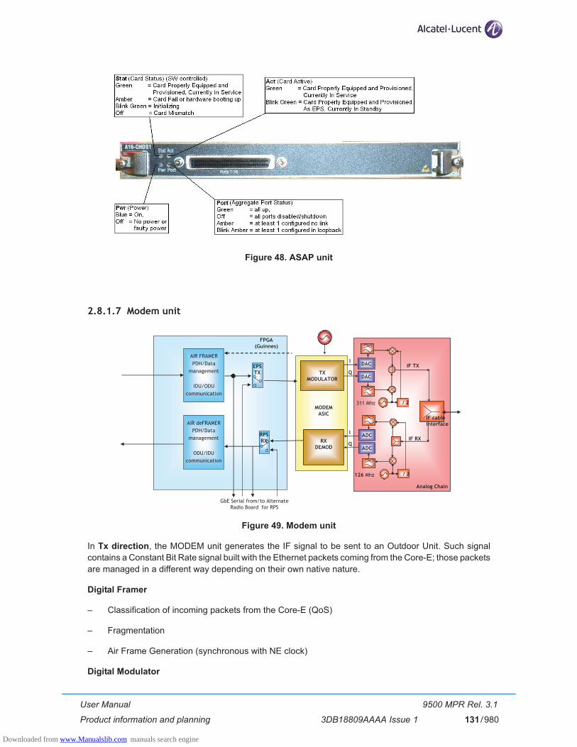
User Manual
Product information and planning
9500 MPR Rel. 3.1
3DB18809AAAA Issue 1 131/980
Figure 48. ASAP unit
2.8.1.7 Modem unit
Figure 49. Modem unit
In Tx direction, the MODEM unit generates the IF signal to be sent to an Outdoor Unit. Such signal contains a Constant Bit Rate signal built with the Ethernet packets coming from the Core-E; those packets are managed in a different way depending on their own native nature.
Digital Framer
– Classification of incoming packets from the Core-E (QoS)
– Fragmentation
– Air Frame Generation (synchronous with NE clock)
Digital Modulator
Analog ChainAnalog Chain
GbE Serial from/to Alternate Radio Board for RPS
TXMODULATOR
RXDEMOD
MODEMASIC
DAC
/ 2
DAC
I
Q
IF RX
311 Mhz
ADC
/ 2
ADC
I
Q
126 Mhz
IF cableinterface
AIR FRAMERPDH/Data
management
IDU/ODUcommunication
EPSTX
AIR deFRAMERPDH/Data
management
ODU/IDUcommunication
RPS RX
FPGA(Guinnes)
IF TX
Downloaded from www.Manualslib.com manuals search engine

User Manual
Product information and planning
9500 MPR Rel. 3.1
3DB18809AAAA Issue 1132/980
TX Analog Chain
– DAC & low pass filtering
– Modulation to 311 MHz IF TX
In Rx direction, the MODEM 300 Module terminates the IF signal coming from the ODU300 extracting the original CBR and then the original Ethernet packets to be given the Core-E which distributes them to the proper Module.
RX Analog Chain
– 126 MHz IF RX demodulation to I & Q
– low pass filtering & ADC
Digital Demodulator
– Carrier & CK recovery
– Equalisation
– Error Correction
Digital Deframer
– RPS (hitless)
– Defragmentation
Figure 50. Modem unit
Transmitter connected to the antenna
Downloaded from www.Manualslib.com manuals search engine

User Manual
Product information and planning
9500 MPR Rel. 3.1
3DB18809AAAA Issue 1 133/980
2.8.1.8 MPT Access Unit (with PFoE)
Figure 51. MPT Access unit (with PFoE) block diagram
The MPT Access Unit is the interface for two MPT: MPT-HC or MPT-MC.
Two MPT-HC or MPT-MC can be connected to one MPT Access unit.
The two MPT can be configured in unprotected or protected configuration.
The connection to the MPT-HC can be realized:
a) by using two connectors:• one DC power Supply connector to send the power supply to the MPT-HC• one Gigabit Ethernet connector (electrical or optical) to send the Ethernet traffic and the Ether-
net control frames to the MPT-HC
b) or by using only one electrical Ethernet cable with the enabling of the PFoE (Power Feed over Ether-net) function (Ethernet traffic + Power Supply on the same cable).
If the optical port has to be used, an SFP plug-in must be installed.
N.B. If has been enabled port #1 (optical or electrical), the associated Power Supply port is #1.
N.B. If has been enabled port #2 (optical or electrical), the associated Power Supply port is #2.
The connection to the MPT-MC is realized by using only one electrical Ethernet cable with the enabling of the PFoE (Power Feed over Ethernet) function (Ethernet traffic + Power Supply on the same cable).
Main Functions
– Provide the power supply interface and the Ethernet interface– Provide the Power Feed over Ethernet function– Lightning and surge protection– Ethernet and power interface supervision– EPS/HSB management function– Clock distribution function
DigitalProcessing
Downloaded from www.Manualslib.com manuals search engine
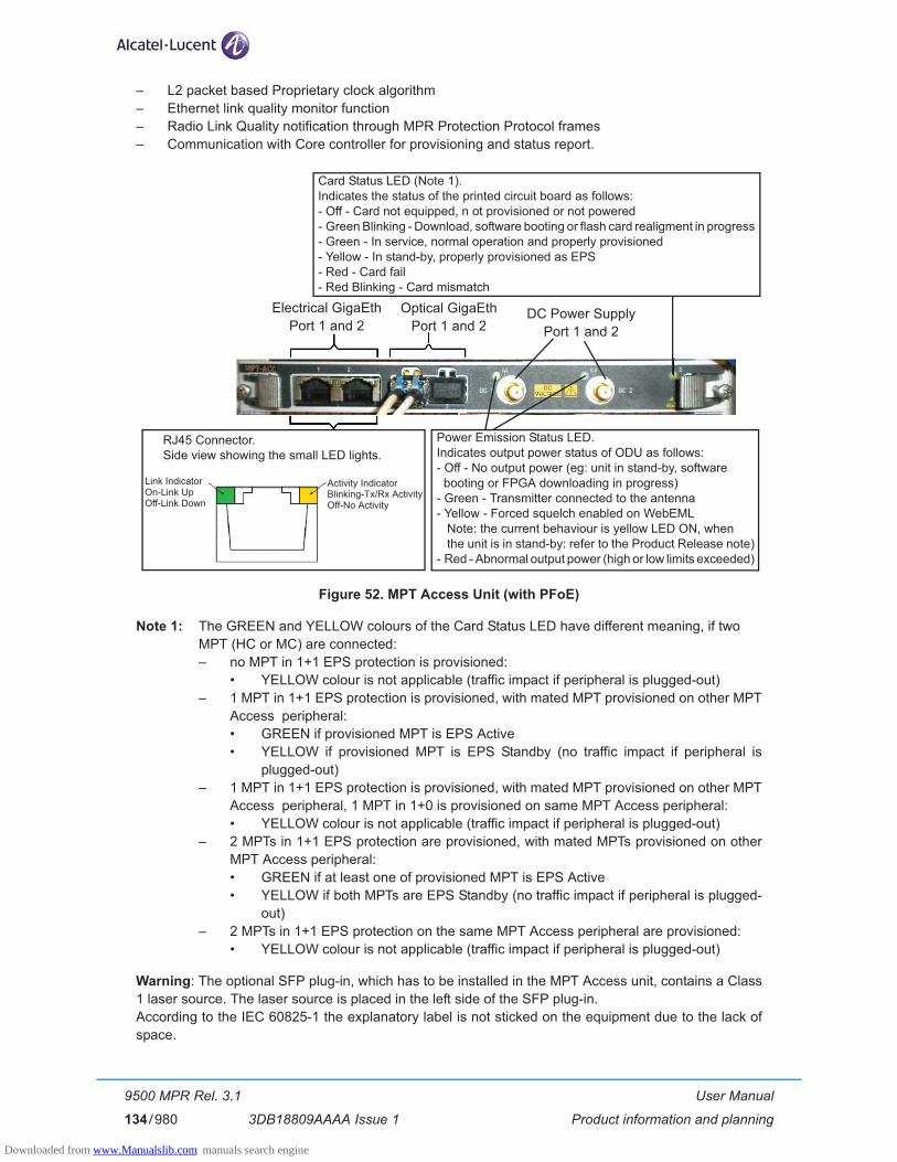
User Manual
Product information and planning
9500 MPR Rel. 3.1
3DB18809AAAA Issue 1134/980
– L2 packet based Proprietary clock algorithm– Ethernet link quality monitor function– Radio Link Quality notification through MPR Protection Protocol frames– Communication with Core controller for provisioning and status report.
Figure 52. MPT Access Unit (with PFoE)
Note 1: The GREEN and YELLOW colours of the Card Status LED have different meaning, if two �MPT (HC or MC) are connected:– no MPT in 1+1 EPS protection is provisioned:
• YELLOW colour is not applicable (traffic impact if peripheral is plugged-out) – 1 MPT in 1+1 EPS protection is provisioned, with mated MPT provisioned on other MPT
Access peripheral: • GREEN if provisioned MPT is EPS Active • YELLOW if provisioned MPT is EPS Standby (no traffic impact if peripheral is
plugged-out) – 1 MPT in 1+1 EPS protection is provisioned, with mated MPT provisioned on other MPT
Access peripheral, 1 MPT in 1+0 is provisioned on same MPT Access peripheral: • YELLOW colour is not applicable (traffic impact if peripheral is plugged-out)
– 2 MPTs in 1+1 EPS protection are provisioned, with mated MPTs provisioned on other MPT Access peripheral: • GREEN if at least one of provisioned MPT is EPS Active • YELLOW if both MPTs are EPS Standby (no traffic impact if peripheral is plugged-
out) – 2 MPTs in 1+1 EPS protection on the same MPT Access peripheral are provisioned:
• YELLOW colour is not applicable (traffic impact if peripheral is plugged-out)
Warning: The optional SFP plug-in, which has to be installed in the MPT Access unit, contains a Class 1 laser source. The laser source is placed in the left side of the SFP plug-in.According to the IEC 60825-1 the explanatory label is not sticked on the equipment due to the lack of space.
Card Status LED (Note 1).Indicates the status of the printed circuit board as follows:- Off - Card not equipped, n ot provisioned or not powered- Green Blinking - Download, software booting or flash card realigment in progress- Green - In service, normal operation and properly provisioned- Yellow - In stand-by, properly provisioned as EPS- Red - Card fail- Red Blinking - Card mismatch
Power Emission Status LED.Indicates output power status of ODU as follows:- Off - No output power (eg: unit in stand-by, software� booting or FPGA downloading in progress)- Green - Transmitter connected to the antenna- Yellow - Forced squelch enabled on WebEML Note: the current behaviour is yellow LED ON, when� the unit is in stand-by: refer to the Product Release note)- Red - Abnormal output power (high or low limits exceeded)
RJ45 Connector.Side view showing the small LED lights.
Link IndicatorOn-Link UpOff-Link Down
Activity IndicatorBlinking-Tx/Rx ActivityOff-No Activity
Electrical GigaEthPort 1 and 2
Optical GigaEthPort 1 and 2
DC Power SupplyPort 1 and 2
Downloaded from www.Manualslib.com manuals search engine

User Manual
Product information and planning
9500 MPR Rel. 3.1
3DB18809AAAA Issue 1 135/980
2.8.1.9 EAS unit
In case more than 6 local Ethernet access are needed (built-in in the Core-E unit), EAS unit (P8ETH) offers additional eight 10/100/1000 Ethernet interfaces.
An embedded 10 Gbit/sec L2 switch is present on the unit.
There are 4 Electrical 10/100/1000 base-T electrical ports and 4 optical SFP (LX and SX).
Figure 53. EAS unit block diagram
Figure 54. EAS unit
Downloaded from www.Manualslib.com manuals search engine

User Manual
Product information and planning
9500 MPR Rel. 3.1
3DB18809AAAA Issue 1136/980
2.8.2 Power Extractor
The Power Extractor, installed close to the MPT-HC, allows to interconnect the MSS and the MPT-HC with a single electrical Ethernet cable by using the “Power Feed over Ethernet” solution (Ethernet traffic and Power Supply on the same cable). The Power Extractor then separates the Power Supply from the Ether-net traffic, which are separately sent to the MPT-HC.
The two cables, interconnecting the Power Extractor to the MPT-HC (the Power Supply cable to be con-nected to the DC Out connector of the Power Extractor and Ethernet cable to be connected to the Data Out connector of the Power Extractor), are provided, already terminated (2 m long), with the Power Extractor itself.
Figure 55. Power Extractor
2.8.3 Power Injector
The Power Injector is an indoor device designed to deliver the DC power supply to MPT (as shown in para-graph 2.1.10 on page 58) by using the same cable carrying the Ethernet traffic.
The Power Injector receives at the input the Ethernet traffic and the power supply on two dedicated con-nectors and sends to the output on one connector the Power Supply + Ethernet Traffic. This solution, called PFoE (Power Feed over Ethernet), is proprietary.
The Power Injector can supply up to 2 MPT.
The two Power Supply Sources provide power supply redundancy.
Main functions of the injector
– Securization of two DC power inputs from -48V battery
– Low pass filtering
– Insertion of the DC voltage on two Ethernet streams to power two MPT units
– Surge protection on both Ethernet output ports (K44 & K45)
Downloaded from www.Manualslib.com manuals search engine

User Manual
Product information and planning
9500 MPR Rel. 3.1
3DB18809AAAA Issue 1 137/980
Power Injector versions
Two versions are available:
1) Power Injector plug-in: installed in the MSS shelf and powered through the backplane.
Figure 56. Power Injector plug-in
The Power Injector plug-in is not managed by MSS. The Plug-in just needs an empty slot to be inserted in. As consequence, no specific commissioning activity is needed to insert a Power Injector plug-in on a existing MSS shelf.
2) Power Injector box: stand-alone box, powered through two connectors on the front providing power supply redandancy. The box can be mounted in a rack by means of a separate bracket. The bracket can support two boxes side by side. Height: 1,3 U.
Figure 57. Power Injector box
Connectors
– Two DC connectors in the front (for box version), or power from the backpanel (for plug-in version).
– Two RJ45 for the data in (DATA)
– Two RJ45 for the data + DC out (DC+DATA)
LEDs
– Two LEDs indicate the presence of DC voltage on each Ethernet output.
Figure 58. Power Injector front panel
Downloaded from www.Manualslib.com manuals search engine

User Manual
Product information and planning
9500 MPR Rel. 3.1
3DB18809AAAA Issue 1138/980
2.8.4 ODU300
The ODUs include a waveguide antenna port, type-N female connector for the ODU cable, a BNC female connector (with captive protection cap) for RSSI access, and a grounding stud.
The ODUs, are designed for direct antenna attachment via a 9500 MPR-E-specific mounting collar supplied with the antennas.
ODU polarization is determined by the position of a polarization rotator fitted within the antenna mounting collar.
A remote ODU mounting kit is also available as an option. These may be used to connect an ODU to a standard antenna, or to a dual-polarized antenna for co-channel link operation.
ODUs are fixed for Tx High or Tx Low operation.
Where two ODUs are to be connected to a single antenna for hot-standby or frequency diversity configurations, a direct-mounting coupler is used. They are available for equal or unequal loss operation. Balanced loss is nominally 3 dB. Unbalanced loss is nominally 1/6 dB.
The ODU assembly meets the ASTME standard for a 2000 hour salt-spray test, and relevant IEC, UL, and Bellcore standards for wind-driven rain.
The ODU housing comprises:
– Cast aluminium base (alloy 380)
– Pressed aluminium cover (sheet grade alloy 1050).
– Base and cover passivated and then polyester powder coated
– Compression seal for base-cover weatherproofing
– Carry-handle
Figure 59. ODU300 housing
ODUs are frequency-band specific, but within each band are capacity-independent up to their design maximums.
Downloaded from www.Manualslib.com manuals search engine

User Manual
Product information and planning
9500 MPR Rel. 3.1
3DB18809AAAA Issue 1 139/980
2.8.4.1 ODU block diagram
Figure 60.shows the ODU block diagram.
Figure 60. ODU block diagram
The quadrature modulated 311 MHz IF signal from the MSS is extracted at the N-Plexer and passed via a cable AGC circuit to an IQ demodulator/modulator.
Here the 311 MHz IF is demodulated to derive the separate I and Q signals using the 10 MHz synchronizing reference signal from the MSS.
These I and Q signals modulate a Tx IF, which has been set to a specific frequency between 1700 and 2300 MHz, such that when mixed with the Tx local oscillator signal (TXLO) in the subsequent mixer stage, provides the selected transmit frequency. Both the IF and Tx local oscillators are synthesizer types.
Between the IQ modulator and the mixer, a variable attenuator provides software adjustment of Tx power.
After the mixer, the transmit signal is amplified in the PA (Power Amplifier) and passed via the diplexer to the antenna feed port.
A microprocessor in the ODU supports configuration of the synthesizers, transmit power, and alarm and performance monitoring. The ODU microprocessor is managed under the NCC microprocessor, with which it communicates via the telemetry channel.
A DC-DC converter provides the required low-voltage DC rails from the -48 Vdc supply.
In the receive direction, the signal from the diplexer is passed via the LNA (Low Noise Amplifier) to the Rx mixer, where it is mixed with the receive local oscillator (RXLO) input to provide an IF of between 1700 and 2300 MHz. It is then amplified in a gain-controlled stage to compensate for fluctuations in receive level, and in the IF mixer, is converted to a 126 MHz IF for transport via the ODU cable to the MSS.
The offset of the transmit frequencies at each end of the link is determined by the required Tx/Rx split. The split options provided are based on ETSI plans for each frequency band. The actual frequency range per band and the allowable Tx/Rx splits are range-limited within 9500 MPR-E to prevent incorrect user selection.
MSS
Downloaded from www.Manualslib.com manuals search engine
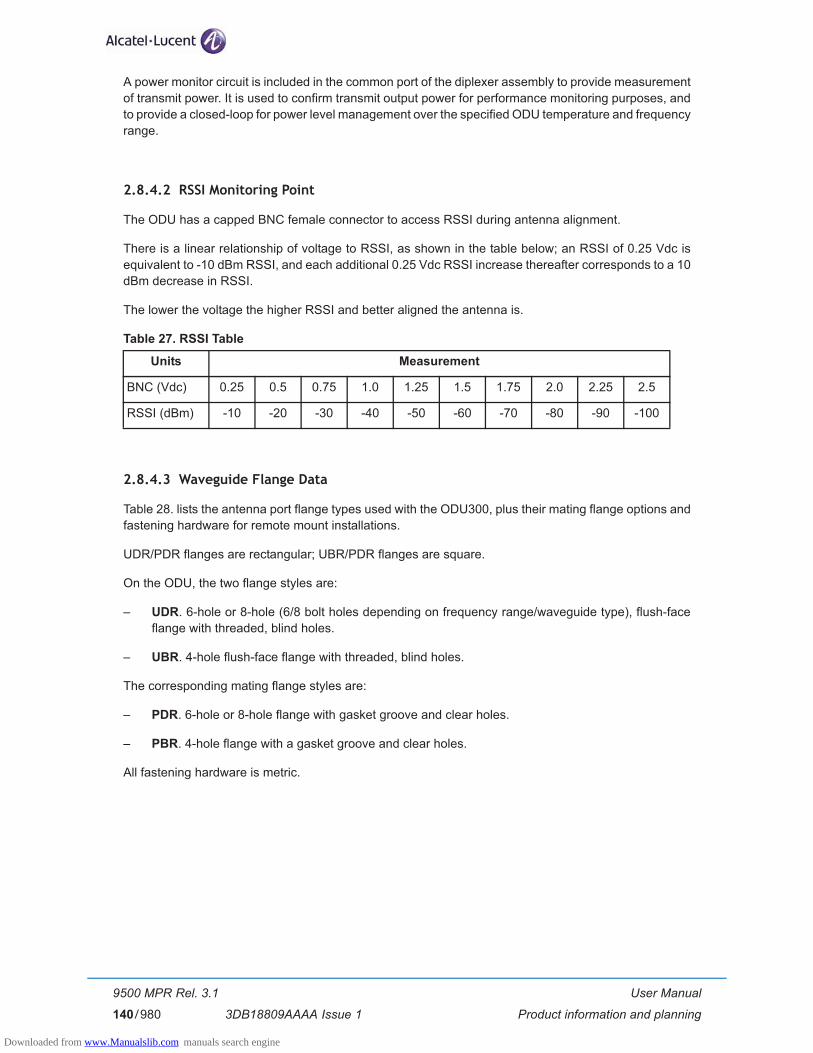
User Manual
Product information and planning
9500 MPR Rel. 3.1
3DB18809AAAA Issue 1140/980
A power monitor circuit is included in the common port of the diplexer assembly to provide measurement of transmit power. It is used to confirm transmit output power for performance monitoring purposes, and to provide a closed-loop for power level management over the specified ODU temperature and frequency range.
2.8.4.2 RSSI Monitoring Point
The ODU has a capped BNC female connector to access RSSI during antenna alignment.
There is a linear relationship of voltage to RSSI, as shown in the table below; an RSSI of 0.25 Vdc is equivalent to -10 dBm RSSI, and each additional 0.25 Vdc RSSI increase thereafter corresponds to a 10 dBm decrease in RSSI.
The lower the voltage the higher RSSI and better aligned the antenna is.
Table 27. RSSI Table
2.8.4.3 Waveguide Flange Data
Table 28. lists the antenna port flange types used with the ODU300, plus their mating flange options and fastening hardware for remote mount installations.
UDR/PDR flanges are rectangular; UBR/PDR flanges are square.
On the ODU, the two flange styles are:
– UDR. 6-hole or 8-hole (6/8 bolt holes depending on frequency range/waveguide type), flush-face flange with threaded, blind holes.
– UBR. 4-hole flush-face flange with threaded, blind holes.
The corresponding mating flange styles are:
– PDR. 6-hole or 8-hole flange with gasket groove and clear holes.
– PBR. 4-hole flange with a gasket groove and clear holes.
All fastening hardware is metric.
Units Measurement
BNC (Vdc) 0.25 0.5 0.75 1.0 1.25 1.5 1.75 2.0 2.25 2.5
RSSI (dBm) -10 -20 -30 -40 -50 -60 -70 -80 -90 -100
Downloaded from www.Manualslib.com manuals search engine
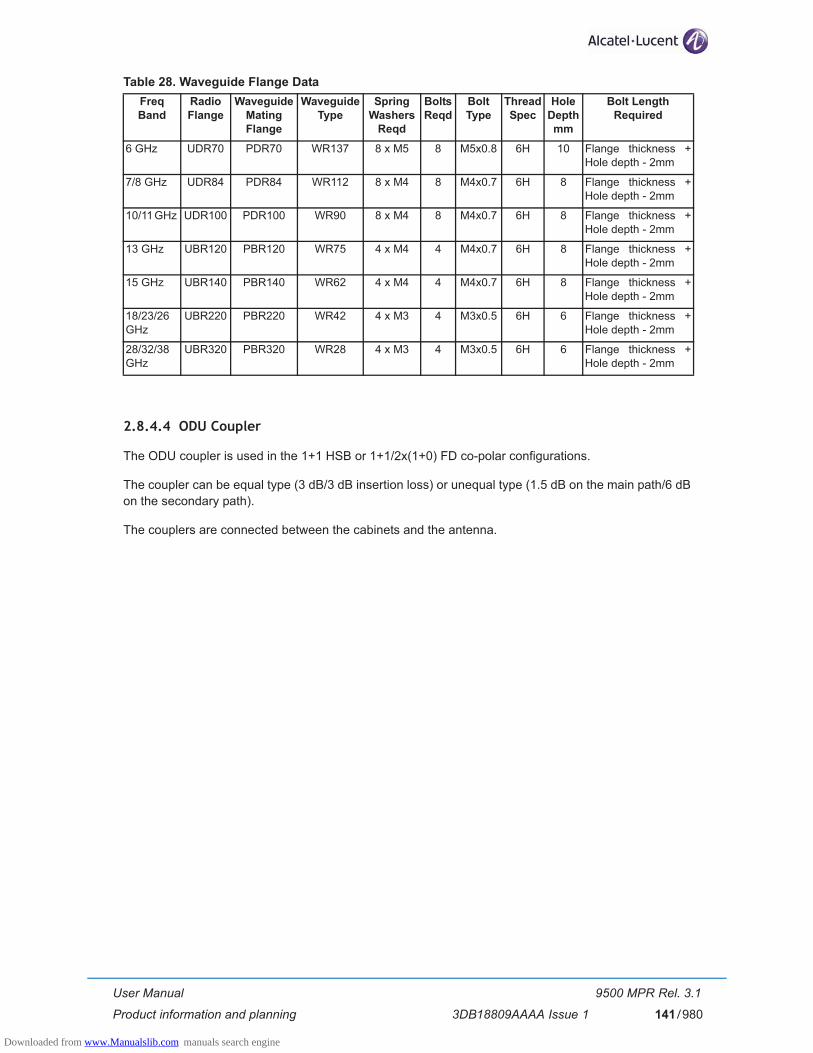
User Manual
Product information and planning
9500 MPR Rel. 3.1
3DB18809AAAA Issue 1 141/980
Table 28. Waveguide Flange Data
2.8.4.4 ODU Coupler
The ODU coupler is used in the 1+1 HSB or 1+1/2x(1+0) FD co-polar configurations.
The coupler can be equal type (3 dB/3 dB insertion loss) or unequal type (1.5 dB on the main path/6 dB on the secondary path).
The couplers are connected between the cabinets and the antenna.
Freq Band
Radio Flange
Waveguide Mating Flange
Waveguide Type
Spring Washers
Reqd
Bolts Reqd
Bolt Type
Thread Spec
Hole Depth mm
Bolt Length Required
6 GHz UDR70 PDR70 WR137 8 x M5 8 M5x0.8 6H 10 Flange thickness + Hole depth - 2mm
7/8 GHz UDR84 PDR84 WR112 8 x M4 8 M4x0.7 6H 8 Flange thickness + Hole depth - 2mm
10/11 GHz UDR100 PDR100 WR90 8 x M4 8 M4x0.7 6H 8 Flange thickness + Hole depth - 2mm
13 GHz UBR120 PBR120 WR75 4 x M4 4 M4x0.7 6H 8 Flange thickness + Hole depth - 2mm
15 GHz UBR140 PBR140 WR62 4 x M4 4 M4x0.7 6H 8 Flange thickness + Hole depth - 2mm
18/23/26 GHz
UBR220 PBR220 WR42 4 x M3 4 M3x0.5 6H 6 Flange thickness + Hole depth - 2mm
28/32/38 GHz
UBR320 PBR320 WR28 4 x M3 4 M3x0.5 6H 6 Flange thickness + Hole depth - 2mm
Downloaded from www.Manualslib.com manuals search engine

User Manual
Product information and planning
9500 MPR Rel. 3.1
3DB18809AAAA Issue 1142/980
2.8.5 MPT-HC
MPT-HC (Microwave Packet Transport) is a Microwave Equipment capable to transport the Ethernet traf-fic over an RF radio channel.
The MPT-HC includes a waveguide antenna port, type-N female connector for the DC connection, a main-tenance connector (with captive protection cap) for RSSI access, 1 electrical GE interface, 2 GE optical interfaces (1 for data, 1 for for RPS) and a grounding stud.
The MPT-HC can be installed on an integrated antenna or on standard poles, wall or pedestal mount, with an appropriate fastening system.
The MPT-HC (one or two depending on the configuration 1+0 or 1+1, each one with a solar shield) incor-porates the complete RF transceiver and can be associated with an integrated or separate antenna.
The cabinet is a very compact and robust weatherproof (IP 67) container, designed to be compatible with hot and very sunny climatic zones.
The MPT-HC can be rapidly installed on standard poles with an appropriate fastening system. The pole mounting is the same for 1+0 or 1+1 configurations from 6 to 38 GHz.
The MPT-HC is fixed by means of quick latches. This system allows to change the MPT-HC without alter-ing antenna pointing.
For 6 GHz & 7/8 GHz, the MPT-HC polarization is determined by the rotation of the MPT-HC in 1+0 con-figuration and by the position of a polarization rotator fitted within the coupler in 1+1 configuration.
For 11 GHz to 38 GHz, the MPT-HC polarization is determined by the rotation of the nose fitted in the antenna port of the MPT-HC in 1+0 configuration and by the position of a polarization rotator fitted within the coupler in 1+1 configuration.
Where two MPT-HC have to be connected to a single antenna for hot-standby or frequency diversity con-figurations, a direct-mounting coupler is used. They are available for equal or unequal loss operation. Equal loss is nominally 3 dB. Unequal is nominally 1/10 dB.
Three mechanical solutions are adopted:
[1] with embedded diplexer for cost optimisation (11 GHz to 38 GHz), where the branching (diplexer) is internal to the MPT-HC cabinet; this type of MPT-HC is identified by one Logistical Item only;
[2] with embedded diplexer for cost optimisation and different mechanics from 11-38 GHz (6 GHz), where the branching (diplexer) is internal to the MPT-HC cabinet; this type of MPT-HC is identified by one Logistical Item only;
[3] with external diplexer: due to a very high number of shifters the diplexer is external for the flexibility of the shifter customization (7 GHz and 8 GHz), where MPT-HC is composed by two independent units: the BRANCHING assembly (containing the diplexer) and the RF TRANSCEIVER assembly (containing the RF section); each of this type of MPT-HC is identified by two Logistical Items, one for the BRANCHING assembly and another for the RF TRANSCEIVER assembly. To read the BRANCHING assembly identification label it is necessary to separate the BRANCHING assembly from the RF TRANSCEIVER assembly.
Downloaded from www.Manualslib.com manuals search engine

User Manual
Product information and planning
9500 MPR Rel. 3.1
3DB18809AAAA Issue 1 143/980
MPT-HC is broken down to the following sections:
– MPT-CB: Common Belt section. This section is Frequency independent, and all the features relevant to this unit are common to all the MPT RF options.
– MPT-RF: Radio Frequency section that is frequency dependent.
Figure 61. MPT system
The MPT-HC interface is based on a Gb Ethernet, that can be either optical or electrical depending on the needs and the cable length. If the optical port has/have to be used (data and/or RPS port), the cor-responfing SFP plug-in must be installed by opening the Cobox.
Figure 62. 11-38 GHz MPT-HC housing
Figure 63. 6 GHz MPT-HC housing
Downloaded from www.Manualslib.com manuals search engine

User Manual
Product information and planning
9500 MPR Rel. 3.1
3DB18809AAAA Issue 1144/980
Figure 64. 7-8 GHz MPT-HC housing
2.8.5.1 MPT-HC block diagram
Figure 65. MPT-HC block diagram
Downloaded from www.Manualslib.com manuals search engine

User Manual
Product information and planning
9500 MPR Rel. 3.1
3DB18809AAAA Issue 1 145/980
2.8.5.1.1 Common Belt section
The Common Belt section is frequency independent. It is the digital section of the MPT-HC.
The main functions are the following:
1) Interfaces the MSS for traffic transport and MSS communication messages in both directions, through one Gigabit Ethernet optical or electrical cable.
2) Micro-Processor for
– Indoor - MPT-HC dialogue– Inter-MPT-HC dialog in 1+1 configurations– HW configuration and monitoring of all MPT-HC parts– Dynamic regulation process such as ATPC
3) Transport of the system reference clock (synchronisation)
4) Switches the traffic and management to the correct port (processor port, radio port)
5) Performs traffic adaptation if needed
6) Performs Quality of Service and policing on flow to be sent over the radio link.
7) Modulation and demodulation of the resulting modem frame
8) In 1+1 configuration manages the switching, forwarding received modem frame to the second MPT-HC and sending built modem frame to the second MPT-HC.
Power supply interface
It is provided by a "N" 50 ohms connector, with the positive to ground.
The power supply is coming from the MSS in the range of -40,5 V to -58 V. MPT-HC input voltage range is from -28 V to -58 V.
Lightning protection
The lightning protection is internal to the MPT-HC. No external protection must be used.
This protection applies to:
– the Ethernet electrical cables
– the power supply coax cable
INCA module
The INCA module hosts the physical Ethernet interfaces:
– One optical SFP device for traffic interface.
– One electrical device for traffic interface.
– One optical SFP device for 1+1 protection interface with the associated MPT-HC.
In order to reach 500m the MPT-HC uses an SFP multimode 805 nm with a 50/125 fibre.
Downloaded from www.Manualslib.com manuals search engine

User Manual
Product information and planning
9500 MPR Rel. 3.1
3DB18809AAAA Issue 1146/980
Tx Side
Following the flow from user Ethernet port to radio, the section performs:
– Reception of incoming Ethernet frames from the optical or electrical user interface (through INCA)
– Recovery of the clock coming from the MSS
– Management of the 1+1 EPS protection layer 2 messages
– Switch of the management frames from user port to internal processor
– Generation of MPT-HC to MPT-HC messages needed for radio link (ATPC, ACM, ...)
– Compression of the TDMoEth frames header (TDM2TDM - MEF8, TDM2ETH - MEF8)
– Management of the Quality of Service
– Fragmentation of the Ethernet frames
– Shaping of the traffic to adapt it to radio bandwidth
– Tx Modem frame building
– In 1+1, duplication of the built Tx modem frame and sending to the second MPT-HC through the pro-tection coupling port
– In 1+1, reception of the Tx modem frame coming from the second MPT-HC
– In 1+1, switch of the Tx modem frame between the local and the one coming from second MPT-HC depending on the EPS position
– Tx Radio frame building (FEC, pilots, ...)
– Synchronisation of the symbol rate to the MSS recovered clock
– Modulation in I and Q analogue signals to be sent to the RF section.
Rx Side
Following the flow from radio to user Ethernet port, the section performs:
– Reception of the I and Q analogue signals coming from the RF section
– Demodulation of the Rx radio frame into Rx modem frame
– In 1+1, Recovery of the symbol clock and duplication to the second MPT-HC
– In 1+1, duplication of the Rx modem frame and sending to the second MPT-HC through the protec-tion coupling port
– In 1+1, reception of the Rx modem frame coming from the second MPT-HC
– In 1+1, hosts the RPS decision machine
– In 1+1, switch of the Rx modem frame between the local and the one coming from second MPT-HC depending on the traditional RPS position and the modem frames quality
– Enhanced RPS
Downloaded from www.Manualslib.com manuals search engine
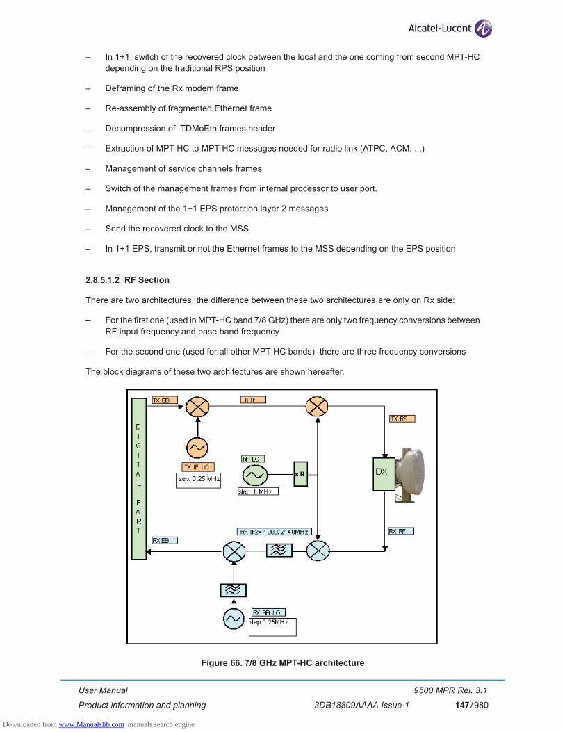
User Manual
Product information and planning
9500 MPR Rel. 3.1
3DB18809AAAA Issue 1 147/980
– In 1+1, switch of the recovered clock between the local and the one coming from second MPT-HC depending on the traditional RPS position
– Deframing of the Rx modem frame
– Re-assembly of fragmented Ethernet frame
– Decompression of TDMoEth frames header
– Extraction of MPT-HC to MPT-HC messages needed for radio link (ATPC, ACM, ...)
– Management of service channels frames
– Switch of the management frames from internal processor to user port.
– Management of the 1+1 EPS protection layer 2 messages
– Send the recovered clock to the MSS
– In 1+1 EPS, transmit or not the Ethernet frames to the MSS depending on the EPS position
2.8.5.1.2 RF Section
There are two architectures, the difference between these two architectures are only on Rx side:
– For the first one (used in MPT-HC band 7/8 GHz) there are only two frequency conversions between RF input frequency and base band frequency
– For the second one (used for all other MPT-HC bands) there are three frequency conversions
The block diagrams of these two architectures are shown hereafter.
Figure 66. 7/8 GHz MPT-HC architecture
Downloaded from www.Manualslib.com manuals search engine

User Manual
Product information and planning
9500 MPR Rel. 3.1
3DB18809AAAA Issue 1148/980
Figure 67. 11 to 38 GHz MPT-HC architecture
Main Functions
1. TX block:
• IF TX Quadrature modulator
• IF_Tx Synthesizer
• RF Up-Converter
• Output power management
2. Tx_Rx Common block:
• RF_LO Synthesizer
3. Rx block:
• LNA
• RF Down Converter
• First IF amplification and overload management
• First IF down conversion
• Second IF amplification and filtering (not present in 7/8 GHz)
• Quadrature demodulator
• Base band filter and AGC loop
Downloaded from www.Manualslib.com manuals search engine

User Manual
Product information and planning
9500 MPR Rel. 3.1
3DB18809AAAA Issue 1 149/980
2.8.5.2 RSSI Monitoring Point
The RSSI is available on the maintenance LEMO connector and is used to manually point the antenna on the field.
The higher the voltage the higher RSSI and better aligned the antenna is.
Table 29. RSSI Table
2.8.5.3 Waveguide Flange Data
Table 30. Waveguide Flange Data
2.8.5.4 MPT-HC Coupler
The coupler is used in the 1+1 HSB or 1+1/2x(1+0) FD co-polar configurations.
The coupler can be equal type (3 dB/3 dB insertion loss) or unequal type (1 dB on the main path/10 dB on the secondary path).
The couplers are connected between the MPT and the antenna.
Units Measurement (with MPT-HC)
BNC (Vdc) 5 4.71 4.12 3.5 2.9 2.3 1.71 1.11 0.59 0.14
RSL (dBm) -10 -20 -30 -40 -50 -60 -70 -80 -90 -100
Waveguide Type
L6 GHz
U6GHz
7 GHz
8 GHz
11 GHz
13 GHz
15 GHz
18 GHz
23 GHz
26 GHz
38 GHz
WR137 WR137 WR113 WR113 WR75 WR62 WR62 WR42 WR42 WR42 WR28
Downloaded from www.Manualslib.com manuals search engine

User Manual
Product information and planning
9500 MPR Rel. 3.1
3DB18809AAAA Issue 1150/980
2.8.6 MPT-HC V2
MPT-HC V2 is similar to MPT-HC from architecture standpoint and can be used as spare part of the MPT-HC. The differences vs MPT-HC are:
– MPT-HC V2 can be natively Ethernet powered through a proprietary PFoE
– MPT-HC V2 is capable to host external modules (RPS module for 1+1 configurations or XPIC_RPS module for XPIC and/or 1+1 configurations).
Two mechanical solutions are adopted:
[1] with embedded diplexer for cost optimisation (6 GHz and 11 GHz to 38 GHz), shown in Figure 68., where the branching (diplexer) is internal to the MPT-HC V2 cabinet; this type of MPT-HC V2 is iden-tified by one Logistical Item only;
[2] with external diplexer: due to an high number of shifters the diplexer is external for the flexibility of the shifter customization (7 GHz and 8 GHz), where MPT-HC V2 is composed by two independent units: the BRANCHING assembly (containing the diplexer) and the RF TRANSCEIVER assembly (containing the RF section); each of this type of MPT-HC V2 is identified by two Logistical Items, one for the BRANCHING assembly and another for the RF TRANSCEIVER assembly. To read the BRANCHING assembly identification label it is necessary to separate the BRANCHING assembly from the RF TRANSCEIVER assembly.
Figure 68. MPT-HC V2 housing (6 GHz and 11 GHz to 38 GHz)
Downloaded from www.Manualslib.com manuals search engine
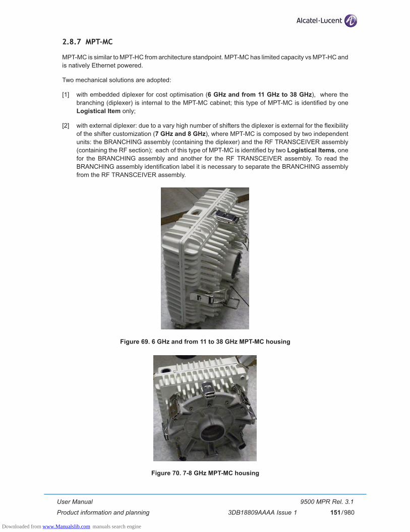
User Manual
Product information and planning
9500 MPR Rel. 3.1
3DB18809AAAA Issue 1 151/980
2.8.7 MPT-MC
MPT-MC is similar to MPT-HC from architecture standpoint. MPT-MC has limited capacity vs MPT-HC and is natively Ethernet powered.
Two mechanical solutions are adopted:
[1] with embedded diplexer for cost optimisation (6 GHz and from 11 GHz to 38 GHz), where the branching (diplexer) is internal to the MPT-MC cabinet; this type of MPT-MC is identified by one Logistical Item only;
[2] with external diplexer: due to a vary high number of shifters the diplexer is external for the flexibility of the shifter customization (7 GHz and 8 GHz), where MPT-MC is composed by two independent units: the BRANCHING assembly (containing the diplexer) and the RF TRANSCEIVER assembly (containing the RF section); each of this type of MPT-MC is identified by two Logistical Items, one for the BRANCHING assembly and another for the RF TRANSCEIVER assembly. To read the BRANCHING assembly identification label it is necessary to separate the BRANCHING assembly from the RF TRANSCEIVER assembly.
Figure 69. 6 GHz and from 11 to 38 GHz MPT-MC housing
Figure 70. 7-8 GHz MPT-MC housing
Downloaded from www.Manualslib.com manuals search engine

User Manual
Product information and planning
9500 MPR Rel. 3.1
3DB18809AAAA Issue 1152/980
2.8.7.1 MPT-MC Coupler
The coupler is used in the 1+1 HSB configuration.
The coupler can be equal type (3 dB/3 dB insertion loss) or unequal type (1 dB on the main path/10 dB on the secondary path).
The couplers are connected between the MPT and the antenna.
Downloaded from www.Manualslib.com manuals search engine
User Manual
Product information and planning
9500 MPR Rel. 3.1
3DB18809AAAA Issue 1 153/980
2.8.8 Protection schemes
2.8.8.1 Protection schemes with ODU300
Supported Protection types:
[1] RPS (Radio Protection Switching) Hitless for each radio direction (RPS-RX)• RPS is distributed in 9500 MSS modules before termination of 9500 MSS frame.
[2] EPS (Equipment Protection Switching) for each module type• Both Working and Spare modules send its own signal to the Core-E. Core-E selects the best
signal.
[3] HSB-TPS (Hot StandBy - Transmission Protection Switch)• Spare ODU module is squelched.
2.8.8.1.1 RPS Switching Criteria
The switching criteria are:
– SF (Signal Fail): generated from transmission and equipment alarms affecting the Rx radio section:
– Demodulator Fail
– IDU-ODU cable loss
– LOF of aggregate signal radio side
– Main and spare ODU, IDU HW failures (card fail)
– HBER (high BER)
– EW (Early Warning)
2.8.8.1.2 EPS Switching Criteria
The switching criteria are:
– Peripheral Card Fail (switching off of the peripheral included)
– Peripheral Card Missing
– LOS of all the tributaries (of course only in case of PDH local access peripheral protection) managed via SW.
2.8.8.1.3 HSB Switching Criteria
The switching criteria are:
– Radio Interface Peripheral Card Fail (switching off of the peripheral included)
– Radio Interface Peripheral Card Missing
– MSS-ODU cable loss
– ODU TX chain alarm (this is an OR of the following alarms: LOS at ODU input, modFail, txFail, ODU card fail).
Downloaded from www.Manualslib.com manuals search engine

User Manual
Product information and planning
9500 MPR Rel. 3.1
3DB18809AAAA Issue 1154/980
2.8.8.2 Protection schemes with MPT-HC/MPT-HC V2
To implement the 1+1 configuration an optical cable must be connected from one MPT-HC/MPT-HC V2 to the second MPT-HC/MPT-HC V2. In Figure 71 Ethernet port 2 of one MPT-HC/MPT-HC V2 is connected to Ethernet port 2 of the second MPT-HC/MPT-HC V2.
N.B. In Figure 71 the two MPT are connected to two different MPT Access units, but they can also be connected to the same MPT Access Unit.
Supported Protection types:
[1] RPS (Radio Protection Switching) Hitless for each radio direction• RPS is implemented directly on the two MPT-HC/MPT-HC V2.
[2] EPS (Equipment Protection Switching) for the MPT-HC/MPT-HC V2• EPS protects the MPT-HC/MPT-HC V2 and the cables connecting it to the MSS.
[3] HSB-TPS (Hot StandBy - Transmission Protection Switch)• Spare ODU module is squelched.
Figure 71. MPT-HC/MPT-HC V2 protection schemes
Downloaded from www.Manualslib.com manuals search engine

User Manual
Product information and planning
9500 MPR Rel. 3.1
3DB18809AAAA Issue 1 155/980
2.8.8.2.1 RPS Switching Criteria
The switching criteria are:
– SF (Signal Fail): generated from transmission and equipment alarms affecting the Rx radio section
– Rx Fail
– Demodulator Fail
– LOF of aggregate signal radio side
– inter-MPT coupling link failure
– HBER (high BER) based on the demodulated erroneous blocks ratio
– EW (Early Warning) based on MSE
Moreover, MPT-HC supports a further embedded functionality called "Enhanced RPS". Enhanced RPS is a frame-based protection mechanism, aimed to reach a quick reaction time and increasing significantly the quality of the radio interface in the Rx side. It assumes the alignment between the 2 received radio channels and it is based on frame by frame selection of the "best" frame between the frames received from the Main and the Spare radio channel. The Enhanced RPS assumes that the "classical" RPS criteria are used to give indication about the "preferred" channel, whose frame has to be selected, when the frame-based choice between the 2 streams is not possible (e.g. due to the frame alignment error). The Enhanced RPS switching criterion depends on the presence of errors in the decoded LDPC word.
2.8.8.2.2 EPS Switching Criteria
The switching criteria are:
– MPT Access Card Fail status – IDU-ODU Connection Failure – ICP alarm – Mated MPT Access card Failure
2.8.8.2.3 HSB Switching Criteria
The switching criteria are:– MPT Access Card Fail status – IDU-ODU Connection Failure – ICP alarm – Incompatible Shifter alarm – Incompatible Frequency alarm – Incompatible Power alarm – Incompatible Modulation Parameters alarm– Mated MPT Access card Failure– Inter-MPT coupling link failure. Where there is a cross configuration (EPS on Spare & TPS on main),
HSB (TPS) will switch and align with EPS position, if there is an inter-MPT coupling link failure.
Downloaded from www.Manualslib.com manuals search engine
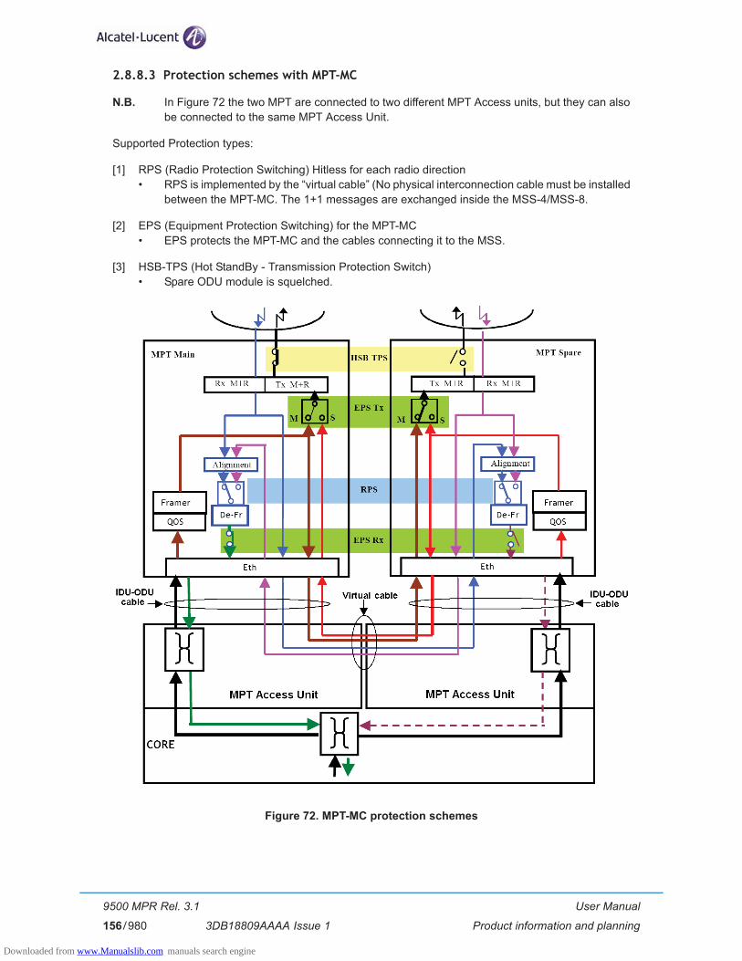
User Manual
Product information and planning
9500 MPR Rel. 3.1
3DB18809AAAA Issue 1156/980
2.8.8.3 Protection schemes with MPT-MC
N.B. In Figure 72 the two MPT are connected to two different MPT Access units, but they can also be connected to the same MPT Access Unit.
Supported Protection types:
[1] RPS (Radio Protection Switching) Hitless for each radio direction• RPS is implemented by the “virtual cable” (No physical interconnection cable must be installed
between the MPT-MC. The 1+1 messages are exchanged inside the MSS-4/MSS-8.
[2] EPS (Equipment Protection Switching) for the MPT-MC• EPS protects the MPT-MC and the cables connecting it to the MSS.
[3] HSB-TPS (Hot StandBy - Transmission Protection Switch)• Spare ODU module is squelched.
Figure 72. MPT-MC protection schemes
Downloaded from www.Manualslib.com manuals search engine

User Manual
Product information and planning
9500 MPR Rel. 3.1
3DB18809AAAA Issue 1 157/980
2.8.8.3.1 RPS Switching Criteria
The switching criteria are:
– SF (Signal Fail): generated from transmission and equipment alarms affecting the Rx radio section
– Rx Fail
– Demodulator Fail
– LOF of aggregate signal radio side
– inter-MPT coupling link failure
– HBER (high BER) based on the demodulated erroneous blocks ratio
– EW (Early Warning) based on MSE
Moreover, MPT-MC supports a further embedded functionality called "Enhanced RPS". Enhanced RPS is a frame-based protection mechanism, aimed to reach a quick reaction time and increasing significantly the quality of the radio interface in the Rx side. It assumes the alignment between the 2 received radio channels and it is based on frame by frame selection of the "best" frame between the frames received from the Main and the Spare radio channel. The Enhanced RPS assumes that the "classical" RPS criteria are used to give indication about the "preferred" channel, whose frame has to be selected, when the frame-based choice between the 2 streams is not possible (e.g. due to the frame alignment error). The Enhanced RPS switching criterion depends on the presence of errors in the decoded LDPC word.
2.8.8.3.2 EPS Switching Criteria
The switching criteria are:
– MPT Access Card Fail status – IDU-ODU Connection Failure – ICP alarm – Mated MPT Access card Failure
2.8.8.3.3 HSB Switching Criteria
The switching criteria are:
– MPT Access Card Fail status – IDU-ODU Connection Failure – ICP alarm – Incompatible Shifter alarm – Incompatible Frequency alarm – Incompatible Power alarm – Incompatible Modulation Parameters alarm– Mated MPT Access card Failure
Downloaded from www.Manualslib.com manuals search engine

User Manual
Product information and planning
9500 MPR Rel. 3.1
3DB18809AAAA Issue 1158/980
2.8.8.4 Core-E protection
The logic of this protection is distributed in each access and radio peripheral unit. All the switching criteria coming from both the Core units, are available (via backpanel) to each peripheral in order to allow to each logic to take the same decision.
Both the Cores (main and spare) send their signals to all the traffic peripherals.
Core protection supports two different types of protection:
– Traffic/services protection (protection of all the transport functions with the exception of the control platform)
– Control Platform protection
In order to provide this protection the Flash Cards on the two Core boards are kept aligned (in terms of SW and configuration data) both in case of new operations done by the management systems and in case of Flash Card replacement.
User Ethernet interfaces protection
In order to support User Ethernet interfaces protection using an external device, the User Ethernet ports of the Core in standby status are switched off.
The switch on of the User Ethernet interfaces when the Core in standby status becomes active, due to operator commands or automatic switch, is done within few seconds. In case of Optical Ethernet interface, the Lambda, Link Length, Connector and Gigabit Ethernet Compliance Code information are read from the active Core.
TMN Local Ethernet interface protection
In order to support TMN Local Ethernet interface protection using an external device, the relevant Ethernet port of the Core in standby status is switched off.
The switch on of the TMN Local Ethernet interface when the Core in standby status becomes active, due to operator commands or automatic switch, is done within 5 seconds.
In order to avoid impact on the Core, the external device used for the TMN Local Ethernet interface pro-tection is kept separate from the one used for protection of User Ethernet interface.
External synchronization interface protection
The Protection of the external synchronization interface is supported. The output port on the stand-by Core is muted.
Node-Timed PDH interface protection
In case of node-timed PDH interface the protection of the NE Clock provided by Core is supported.
Core protection restoration mode
The restoration mode is always non revertive: the Core main becomes active as soon as it has recovered from failure or when a switch command is released.
Downloaded from www.Manualslib.com manuals search engine

User Manual
Product information and planning
9500 MPR Rel. 3.1
3DB18809AAAA Issue 1 159/980
2.8.8.4.1 Core-E protection Switching Criteria
The switching criteria are:
– Core Card Fail– Core Card Missing– Control Platform operational status failure– Flash Card realignment in progress– Flash Card failure
If the “Ethernet LOS Criteria” feature has been enabled the following additional switching criteria are added:
– Card Fail of SFP optical module– Card Missing of SFP optical module– LOS of any Electrical User Ethernet interfaces, including the LOS of the forth User Ethernet interface
working as TMN Local Ethernet interface.
N.B. In case of stand-by Flash Card realignment in progress, the application SW refuses/removes a manual switch command.
2.8.8.4.2 Port #5 and port #6 protection
– If in the Port #5 and/or port #6 a 2xE1 SFP or EoSDH SFP has been installed, the protection is implemented by using special splitters (refer to paragraph 4.1.3.3 on page 584 and paragraph 4.1.3.4 on page 584).
Downloaded from www.Manualslib.com manuals search engine

User Manual
Product information and planning
9500 MPR Rel. 3.1
3DB18809AAAA Issue 1160/980
2.8.9 Stacking for EAS unit/MPT Access unit
Two EAS units or two MPT Access units installed on the same row (i.e. slot #3 and slot #4) are automat-ically configured in stacking configuration.
The benefits of the stacking are:
1) the intra-board traffic between the two units does not transit through the Core-E unit (no traffic impact in case of Core-E switch);
2) each port of the units can be individually segregated from the other ports.
2.8.10 Ethernet Ring Protection
The implemented Ethernet Ring Protection Switching (ERPS) is according to ITU-T G.8032 recommen-dation. The ERPS is a protection mechanism for Ethernet ring topologies.
2.8.10.1 Definitions
2.8.10.1.1 Topology
An ERPS Topology is a collection of Ethernet Ring Nodes forming a closed physical loop. Each Ethernet Ring Node is connected to two adjacent Ethernet Ring Nodes via a duplex communications facility. Only one topology is supported.
Note: The minimum number of Ethernet Ring Nodes in an Ethernet Ring is 3 and the max. number is 16.
2.8.10.1.2 Ring Link and Ring Port
Each Ethernet Ring Node is connected to adjacent Ethernet Ring Nodes participating in the same ERPS Topology, using two independent Ring Links. A Ring Link is bounded by two adjacent Ethernet Ring Nodes and a port for a Ring Link is called a Ring Port.
2.8.10.1.3 Ring Protection Link (RPL)
The loop avoidance in the ring is achieved by guaranteeing that, at any time, traffic may flow on all but one of the Ring Links. This particular link is called the Ring Protection Link (RPL).
2.8.10.1.4 RPL Owner
One designated node, the RPL Owner, is responsible to block traffic over the RPL.
Under a ring failure condition, the RPL Owner is responsible to unblock the RPL, allowing the RPL to be used for traffic.
2.8.10.1.5 R-APS Protocol
An APS protocol, called R-APS (Ring Automatic Protection Switching), is used to coordinate the protec-tion actions over the ring.
Downloaded from www.Manualslib.com manuals search engine

User Manual
Product information and planning
9500 MPR Rel. 3.1
3DB18809AAAA Issue 1 161/980
2.8.10.1.6 ERPS Instance
An ERPS Instance is an entity responsible for the protection of a subset of the VLANs that transport traffic over the physical ERPS Topology. Each ERPS Instance is independent of other ERPS Instances that may be configured on the physical ERPS Topology. Only two ERPS instances are supported.
Each ERPS Instance has its own RPL and RPL Owner.
Additionally, an independent session of R-APS protocol is used, over a dedicated R-APS VID, for the ERPS Instance protection coordination.
2.8.10.2 ERPS operation
The protection switching mechanism is based on the Automatic Protection Switching protocol for Ethernet ring topologies (called R-APS). This protocol is used to coordinate the protection actions over the ring.
The fundamentals of this ring protection switching architecture are:
– principle of loop avoidance.
– utilization of learning, forwarding, and address table mechanisms defined in the Ethernet flow for-warding function.
The loop avoidance in the ring is achieved by guaranteeing that, at any time, traffic may flow on all but one of the ring links. This particular link is called the Ring Protection Link (RPL).
Under normal conditions this link is blocked, i.e., not used for traffic. One designated node, the RPL Owner, is responsible to block traffic over the RPL.
Under a ring failure condition, the RPL owner is responsible to unblock the RPL, allowing the RPL to be used for traffic.
Figure 73. Normal Operation (No-fault)
Downloaded from www.Manualslib.com manuals search engine

User Manual
Product information and planning
9500 MPR Rel. 3.1
3DB18809AAAA Issue 1162/980
Figure 74. Single link failure
Two ERPS Control Processes are instantiated on each ring’s node. Each instance selects its own RPL and RPL Owner.
The ERPS Control Process controls the forwarding function to perform the following actions:
– to disable forwarding over the set of VLANs assigned to the ERPS instance corresponding to blocked ring links;
– to flush the learned MAC address table.
Only revertive switching mechanism is supported.
The Wait-to-Restore is managed by the RPL Owner, it is configured by the operator in 1 minute steps between 1 and 12 minutes. The default value is 5 minutes.
Note: In case of a double failure, if the restoring of the two failures takes place at the same time, an out of service equal to the WTR could occur. To note that a switching off of a single NE causes a double failure in the Ring.
A Guard Timer is used to prevent ring nodes from receiving outdated R-APS messages. During the dura-tion of the guard timer, all received R-APS messages are ignored by the ERPS Control Process. The period of the guard timer may be configured by the operator in 10 ms steps between 10 ms and 2 seconds, with a default value of 500 ms.
The Holdoff timer is not managed and fixed to 0 since no server layer protection switching mechanism are present. The Ethernet MAC (ETH) layer, where the ERPS take place, is supported by radio links acting as Ethernet PHY (ETY) layer in 1+0 configuration.
Since the ERPS instances operate “per VLAN” on a logical ring protecting a set of VLANs, this set must consequently be configured.
Downloaded from www.Manualslib.com manuals search engine

User Manual
Product information and planning
9500 MPR Rel. 3.1
3DB18809AAAA Issue 1 163/980
Figure 75. Multiple ERPS instances (Normal No-fault Operation)
Figure 76. Multiple ERPS instances (Single Link Failure)
Downloaded from www.Manualslib.com manuals search engine

User Manual
Product information and planning
9500 MPR Rel. 3.1
3DB18809AAAA Issue 1164/980
2.8.11 Radio Transmission Features with ODU300
2.8.11.1 Frequency Agility
The Frequency Agility feature gives the Operator the possibility to set via ECT the frequency of a single Transceiver within a chosen sub–band to select the RF working channel. This implies benefits for spare parts, order processing and frequency co–ordination.
2.8.11.2 Automatic Transmit Power Control (ATPC)
The Automatic Transmit Power Control (ATPC) function automatically increases or decreases the trans-mit output power upon request from the opposite terminal. The opposite terminal constantly monitors Receive Signal Level (RSL), receive signal quality, and aggregate Bit Error Rate (BER) of the receive sig-nal.
When ATPC Enabled is checked on the Modem Card Settings screen, the transmit output will remain at it's lowest level until a fade occurs (or a receive circuit alarm is detected). When the change in RSL is detected at the receive end, a command is sent to the transmit end to increase power in 1 dB steps to it's highest level. After the fade is over, the receive end commands the transmit power to decreases in 1 dB steps to the lowest level.
The ATPC range (high and low limits) is variable, determined by link distance, link location, and link fre-quency. When ATPC Enabled is checked, the range values are shown in parenthesis (minimum - maxi-mum) following ATPC Range.
When ATPC Enabled is not checked on the Modem Card Settings screen, the transmit output will always operate at it's highest level.
2.8.11.3 Transmitted power control: RTPC function
The capability to adjust the transmitted power in a static and fixed way (RTPC = Remote Transmit Power Control) has been introduced for those countries where, due to internal rules, the ATPC function is not accepted or for those hops in which due to the short length and interface problems, a fixed reduced transmitted power is preferred. The range of the possible attenuation depends on the frequency band involved. The setting of the transmitted power can be performed locally through ECT.
Output power is band and modulation dependent.
2.8.11.4 Power Monitoring
The ODU300 incorporates a detector for Tx power measurement. It is used to provide measurement of forward power as a performance parameter, and to provide a calibration input for transmitter operation over temperature and output range.
Viewed Tx power ranges always match the capabilities of the ODU300 for a given modulation. When modulation is changed, the WebEML automatically adjusts/restricts Tx Power to be within valid range.
2.8.11.5 Adaptive Equalization
Adaptive equalization (AE) is employed to improve reliability of operation under dispersive fade conditions, typically encountered over long and difficult paths.
This is achieved through a multi-tap equalizer consisting of two registers, one with feed-forward taps, the other with feed-back taps. Each of these registers multiply successive delayed samples of the received signal by weighting-coefficients to remove propagation induced inter-symbol interference.
Downloaded from www.Manualslib.com manuals search engine
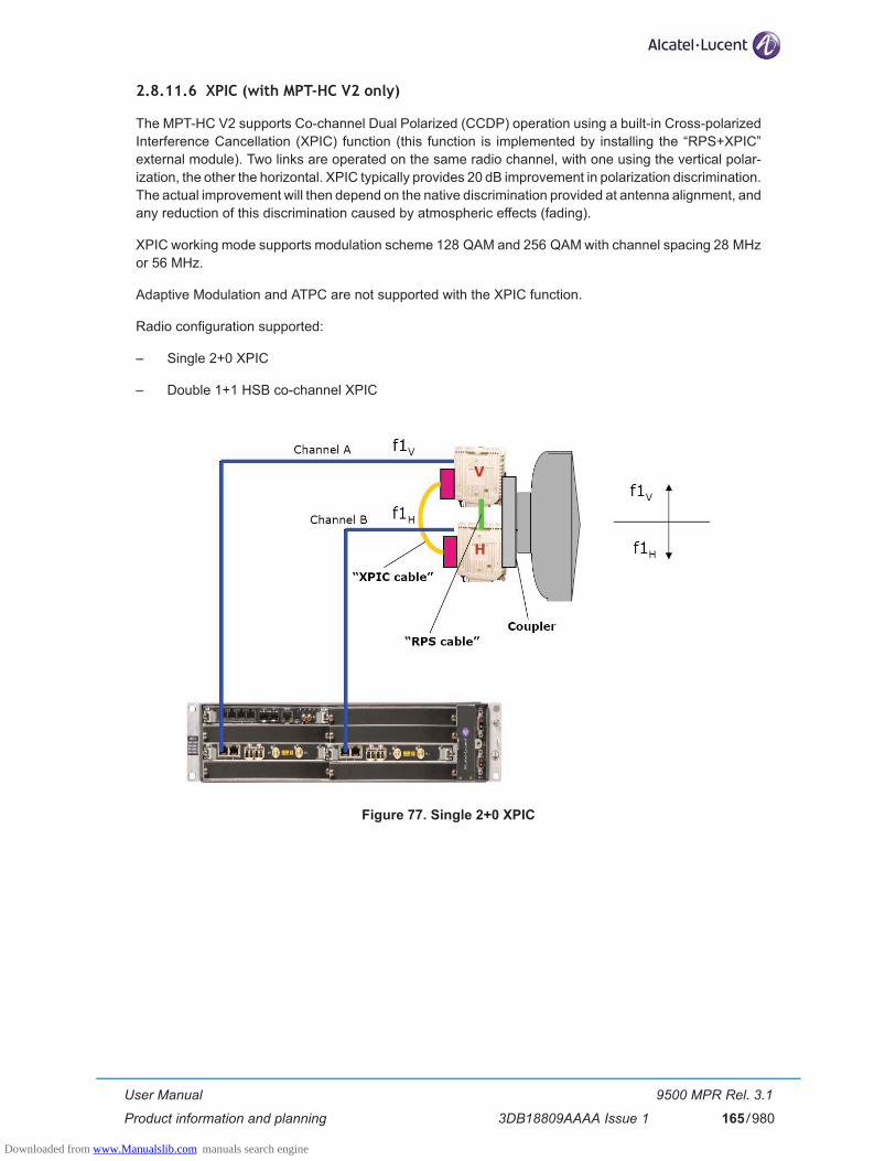
User Manual
Product information and planning
9500 MPR Rel. 3.1
3DB18809AAAA Issue 1 165/980
2.8.11.6 XPIC (with MPT-HC V2 only)
The MPT-HC V2 supports Co-channel Dual Polarized (CCDP) operation using a built-in Cross-polarized Interference Cancellation (XPIC) function (this function is implemented by installing the “RPS+XPIC” external module). Two links are operated on the same radio channel, with one using the vertical polar-ization, the other the horizontal. XPIC typically provides 20 dB improvement in polarization discrimination. The actual improvement will then depend on the native discrimination provided at antenna alignment, and any reduction of this discrimination caused by atmospheric effects (fading).
XPIC working mode supports modulation scheme 128 QAM and 256 QAM with channel spacing 28 MHz or 56 MHz.
Adaptive Modulation and ATPC are not supported with the XPIC function.
Radio configuration supported:
– Single 2+0 XPIC
– Double 1+1 HSB co-channel XPIC
Figure 77. Single 2+0 XPIC
Downloaded from www.Manualslib.com manuals search engine

User Manual
Product information and planning
9500 MPR Rel. 3.1
3DB18809AAAA Issue 1166/980
Figure 78. Double 1+1 HSB co-channel XPIC
2.8.11.7 Link identifier
The amount of microwave links, especially in urban areas puts the problem of possible interferences during installation and turn-on phase.
The digital frame incorporates link identity coding capabilities to prevent the capture of an unwanted signal.
Link identifier management can be enabled or disabled by the management systems.
Downloaded from www.Manualslib.com manuals search engine

User Manual
Product information and planning
9500 MPR Rel. 3.1
3DB18809AAAA Issue 1 167/980
2.8.11.8 Loopbacks with ODU300
To facilitate the installation/commissioning and the remote maintenance one loopback is available.
As the activation of a loopback affects the traffic, the presence of a loopback is indicated to the management systems as an abnormal condition.
The loopback is "loop and cut" type (the signal sent after the loopback execution is the same signal sent back).
The loopback supported by the Radio board is shown in the following figure.
Figure 79. Available loopbacks
1) IF Radio loopback: is implemented in the analog IF part of the ODU300 Radio Module, the traffic received from switch side is redirected toward the switch itself; this loopback can be activated only on the aggregate traffic. When this loop is enabled the behaviour is the following:
– TDM2TDM flows: before transmitting the packets towards the switch, the FPGA looking the VLAN will rebuild the right Ethernet header.
– TDM2ETH flows: before transmitting the packets towards the switch, the FPGA looking the VLAN will rebuild the right Ethernet header.
– The Ethernet flows are dropped.
PDH board RADIO board
CORESWITCHNxE1 LIU FPGA SerDes FPGA
MODEM
1
FPGA
Downloaded from www.Manualslib.com manuals search engine

User Manual
Product information and planning
9500 MPR Rel. 3.1
3DB18809AAAA Issue 1168/980
2.8.12 Radio Transmission Features with MPT-HC/MPT-HC V2/MPT-MC
2.8.12.1 Frequency Agility
The Frequency Agility feature gives the Operator the possibility to set via ECT the frequency of a single Transceiver within a chosen sub–band to select the RF working channel. This implies benefits for spare parts, order processing and frequency co–ordination.
2.8.12.2 Automatic Transmit Power Control (ATPC)
The Automatic Transmit Power Control (ATPC) function automatically increases or decreases the trans-mit output power upon request from the opposite terminal. The opposite terminal constantly monitors Receive Signal Level (RSL), receive signal quality, and aggregate Bit Error Rate (BER) of the receive sig-nal.
When the ATPC is Enabled the transmit output will remain at it's lowest level until a fade occurs (or a receive circuit alarm is detected). When the change in RSL is detected at the receive end, a command is sent to the transmit end to increase power in 1 dB steps to it's highest level. After the fade is over, the receive end commands the transmit power to decreases in 1 dB steps to the lowest level.
The ATPC range (high and low limits) is variable, determined by link distance, link location, and link fre-quency. When ATPC Enabled is checked, the range values are shown in parenthesis (minimum - maxi-mum) following ATPC Range.
When the ATPC is disabled the transmit output will always operate at it's highest level.
2.8.12.3 Transmitted power control: RTPC function
The capability to adjust the transmitted power in a static and fixed way (RTPC = Remote Transmit Power Control) has been introduced for those countries where, due to internal rules, the ATPC function is not accepted or for those hops in which due to the short length and interface problems, a fixed reduced transmitted power is preferred. The range of the possible attenuation depends on the frequency band involved. The setting of the transmitted power can be performed locally through ECT.
Output power is band and modulation dependent.
2.8.12.4 Power Monitoring
The MPT-HC/MPT-HC V2 incorporates a detector for Tx power measurement. It is used to provide measurement of forward power as a performance parameter, and to provide a calibration input for transmitter operation over temperature and output range.
Viewed Tx power ranges always match the capabilities of the MPT-HC/MPT-HC V2 for a given modulation. When modulation is changed, the WebEML automatically adjusts/restricts Tx Power to be within valid range.
2.8.12.5 Adaptive Equalization
Adaptive equalization (AE) is employed to improve reliability of operation under dispersive fade conditions, typically encountered over long and difficult paths.
Downloaded from www.Manualslib.com manuals search engine

User Manual
Product information and planning
9500 MPR Rel. 3.1
3DB18809AAAA Issue 1 169/980
This is achieved through a multi-tap equalizer consisting of two registers, one with feed-forward taps, the other with feed-back taps. Each of these registers multiply successive delayed samples of the received signal by weighting-coefficients to remove propagation induced inter-symbol interference.
2.8.12.6 Link identifier
The amount of microwave links, especially in urban areas puts the problem of possible interferences during installation and turn-on phase.
The digital frame incorporates link identity coding capabilities to prevent the capture of an unwanted signal.
In case of “Link Identifier Mismatch” all the traffic is dropped.
The Link identifier management can be enabled or disabled by the management systems.
2.8.12.7 Loopbacks with MPT-HC/MPT-HC V2/MPT-MC
To facilitate the installation/commissioning and the remote maintenance one loopback is available.
As the activation of a loopback affects the traffic, the presence of a loopback is indicated to the management systems as an abnormal condition.
The loopback is "loop and continue" type (the signal sent after the loopback execution is the same signal sent back).
The loopbacks supported are shown in the following figure.
Figure 80. Available loopbacks
1) Core facing radio loopback: this loopback routes data from the output of the Tx Data Awareness block (after compression) to the input of the Rx data awareness (decompression). This is an internal loopback provided by the MPT FPGA. It is a Loop and Continue. It is possible to enable this loopback only at aggregate level. When this loopback is activated the behavior is the following: – Compressed flows (TDM2TDM,TDM2ETH and ATM PW) are forwarded back to Core
module with proper assignment of source and destination MAC addresses (e.g. incoming MAC SA is used as MAC DA for looped frame, while MAC SA in the looped frame is the MAC assigned to slot hosting radio card).
– For TDM2ETH flows the loopback works only if the ECID Tx and ECID Rx are the same, in case of ECID Tx is different form ECID Rx the loopback doesn't work.
– For ATM PW flows the loopback works only if the Inbound and Outbound PW Labels are the same, in case they are different the loopback doesn't work.
PDH boardMPT Access
board
CORESWITCHNxE1 LIU FPGA SerDesFPGA FPGA
1 2
MPT-HC
FPGA
Downloaded from www.Manualslib.com manuals search engine

User Manual
Product information and planning
9500 MPR Rel. 3.1
3DB18809AAAA Issue 1170/980
– Generic Ethernet flows are dropped. The Core facing radio loopback operation implies the "Automatic Tx mute" before the execution of the command and the "Tx mute removal" after the execution of the loopback command.
2) Radio facing Circuit loopback: remote loopback allows an over-the-air loopback test to be per-formed when the modem is operating in a continuous mode. The loopback is internally provided by the MPT FPGA and connects the Receive data interface to the Transmit data interface. This is a line external loopback. This loopback is a Loop and Continue. It is possible to enable this loopback only at aggregate level. When this loop is enabled the expected behavior is the following: – Compressed flows (TDM2TDM,TDM2ETH and ATM PW) are forwarded back to Core
module with proper assignment of source and destination MAC addresses (e.g. incoming MAC SA is used as MAC DA for looped frame, while MAC SA in the looped frame is the MAC assigned to slot hosting radio card).
– For TDM2ETH flows the loopback works only if the ECID Tx and ECID Rx are the same, in case of ECID Tx is different form ECID Rx the loopback doesn't work.
– For ATM PW flows the loopback works only if the Inbound and Outbound PW Labels are the same, in case they are different the loopback doesn't work.
– Generic Ethernet flows are dropped.
2.8.12.8 Loopback activation
The loopback can be activated by each management system (local or remote). The activation command permits to define the duration of the loopback (time-out).
The two loopbacks (Core facing and Radio facing) cannot be supported at the same time.
The time-out period starts at the activation time and expires at the end of the period spontaneously in the NE, a part for the case in which another reconfiguration of the time-out period is requested at the operator interface during the activation time. In this case, if the loopback point is still active because the activation time-out is not expired yet, the time-out period is reconfigurable and the specified time range starts again from the new updated activation date, overwriting the previous activation date and time-out values.
2.8.12.9 Loopback life time
In order to avoid the risk of a permanent disconnection from ECT/NMS of a remote NE after the execution of a loopback, a time-out mechanism is supported.
The management system's operator has to provide the time range of the loopback time-out period expressed in hours/minutes starting from the time of the loopback activation.
A default time-out period may be suggested at the operator interface, even if it could be modified on user-needs basis.
After the NE reset, the activation of each loopback point is lost and must be recreated again if needed, starting with a new time-out period.
Downloaded from www.Manualslib.com manuals search engine

User Manual
Product information and planning
9500 MPR Rel. 3.1
3DB18809AAAA Issue 1 171/980
2.8.13 TMN interfaces
On 9500 MPR-E Network Element the following types of TMN communication interfaces are present:
– TMN channel carried by Ethernet frames in the dedicated TMN port (on the front panel of the Core-E module) (this port is normally used to connect the WebEML);
– TMN channel carried up to 512 kbit/s channel inside Radio frame;
– TMN channel carried by Ethernet frames in User Ethernet port# 4 (on the front panel of the Core-E module);
– Two TMN In-band interfaces (by using the Ethernet traffic ports).
2.8.14 Admission control in Adaptive Modulation (only with ODU300)
With the MPT-HC or MPT-HC V2 or MPT-MC the Admission Control is always enabled (and cannot be disabled). The totat available capacity is the capacity available with the minimum modulation scheme.
2.8.14.1 What does “Admission Control” mean?
The Admission Control is a feature that is available only when operating in Adaptive modulation. It ensures that the requested TDM flows are kept when the modulation scheme is downgraded automatically by the system due to the degraded propagation condition.
The Admission Control check is optional: from WebEML, it is possible to decide to enable or not the admis-sion control check (default value is Enabled).
2.8.14.2 Radio capacity in case of adaptive modulation
When the terminal operates in adaptive modulation, it is possible to commission a total capacity of both Ethernet and TDM traffic, up to a bandwidth corresponding to the maximum modulation scheme chosen by the operator. The Table 2. summarizes the E1 equivalent capacity supported by the MPR when using the adaptive modulation. This capacity depends on the channel spacing and the modulation scheme.
2.8.14.3 Adaptive modulation and admission control enabled
The Admission Control feature allows the operator to protect the TDM traffic when this kind of traffic is provisioned.
When admission control is enabled (default operator choice), the whole TDM traffic is kept. The maximum number of E1 links that can be provisioned (or cross-connected in a given radio direction) is the one that is fitting with 4QAM capacity.
N.B. There is no possibility to provision a number of E1s greater than the one fitting in 4QAM mod-ulation. Indeed, as all the E1 links have the same priority, it is not possible from a system point of view to decide "which" E1s should be dropped when the modulation scheme is downgraded from 16QAM to 4QAM. To secure provisioning and commissioning operations, the admission control check at WebEML level has been inserted, avoiding a possible mistake from the user to provision a number of E1s that are not fitting inside 4QAM bandwidth.
Note
Downloaded from www.Manualslib.com manuals search engine
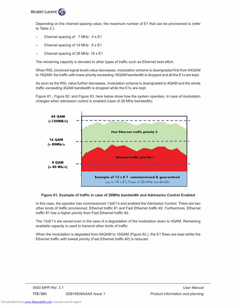
User Manual
Product information and planning
9500 MPR Rel. 3.1
3DB18809AAAA Issue 1172/980
Depending on the channel spacing value, the maximum number of E1 that can be provisioned is (refer to Table 2.):
– Channel spacing of 7 MHz: 4 x E1
– Channel spacing of 14 MHz: 8 x E1
– Channel spacing of 28 MHz: 18 x E1
The remaining capacity is devoted to other types of traffic such as Ethernet best effort.
When RSL (received signal level) value decreases, modulation scheme is downgraded first from 64QAM to 16QAM: the traffic with lower priority exceeding 16QAM bandwidth is dropped and all the E1s are kept.
As soon as the RSL value further decreases, modulation scheme is downgraded to 4QAM and the whole traffic exceeding 4QAM bandwidth is dropped while the E1s are kept.
Figure 81., Figure 82. and Figure 83. here below show how the system operates, in case of modulation changes when admission control is enabled (case of 28 MHz bandwidth).
Figure 81. Example of traffic in case of 28MHz bandwidth and Admission Control Enabled
In this case, the operator has commissioned 13xE1’s and enabled the Admission Control. There are two other kinds of traffic provisioned, Ethernet traffic #1 and Fast Ethernet traffic #2. Furthermore, Ethernet traffic #1 has a higher priority than Fast Ethernet traffic #2.
The 13xE1’s are saved even in the case of a degradation of the modulation down to 4QAM. Remaining available capacity is used to transmit other kinds of traffic.
When the modulation is degraded from 64QAM to 16QAM (Figure 82.), the E1 flows are kept whilst the Ethernet traffic with lowest priority (Fast Ethernet traffic #2) is reduced.
Downloaded from www.Manualslib.com manuals search engine
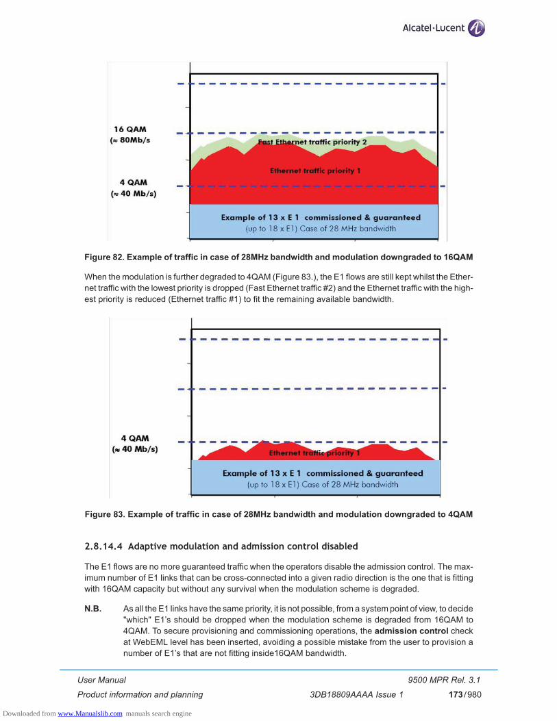
User Manual
Product information and planning
9500 MPR Rel. 3.1
3DB18809AAAA Issue 1 173/980
Figure 82. Example of traffic in case of 28MHz bandwidth and modulation downgraded to 16QAM
When the modulation is further degraded to 4QAM (Figure 83.), the E1 flows are still kept whilst the Ether-net traffic with the lowest priority is dropped (Fast Ethernet traffic #2) and the Ethernet traffic with the high-est priority is reduced (Ethernet traffic #1) to fit the remaining available bandwidth.
Figure 83. Example of traffic in case of 28MHz bandwidth and modulation downgraded to 4QAM
2.8.14.4 Adaptive modulation and admission control disabled
The E1 flows are no more guaranteed traffic when the operators disable the admission control. The max-imum number of E1 links that can be cross-connected into a given radio direction is the one that is fitting with 16QAM capacity but without any survival when the modulation scheme is degraded.
N.B. As all the E1 links have the same priority, it is not possible, from a system point of view, to decide "which" E1’s should be dropped when the modulation scheme is degraded from 16QAM to 4QAM. To secure provisioning and commissioning operations, the admission control check at WebEML level has been inserted, avoiding a possible mistake from the user to provision a number of E1’s that are not fitting inside16QAM bandwidth.
Downloaded from www.Manualslib.com manuals search engine

User Manual
Product information and planning
9500 MPR Rel. 3.1
3DB18809AAAA Issue 1174/980
Depending on the channel spacing value, the maximum number of E1’s that can be provisioned is (refer to Table 2.):
– Channel spacing of 7 MHz: 8 x E1
– Channel spacing of 14 MHz: 18 x E1
– Channel spacing of 28 MHz: 37 x E1
The remaining capacity is devoted to other types of traffic such as Ethernet best effort.
When RSL (received signal level) value decreases, the modulation scheme is downgraded first from 64QAM to 16QAM and all E1 flows are kept because there is enough bandwidth to transmit them. When the modulation further degrades to 4QAM, all E1 flows are dropped because there is no way to define any kind of priority among them. The remaining bandwidth is filled with other traffics.
N.B. It might happen that some E1(s) are temporarily up and transmitting, but this is a random behav-iour without any predefined mechanism, there is no control at all performed on the E1 links.
This feature addresses the need of transmitting a high number of E1’s, without giving up the benefits of adaptive modulation for Ethernet traffic.
Figure 84., Figure 85. and Figure 86. show how the system operates in case of modulation changes when admission control is disabled (case of 28 MHz bandwidth).
Figure 84. Example of traffic in case of 28MHz bandwidth and Admission Control Disabled
In this case, the operator has commissioned 32xE1’s and chosen to disable the Admission Control. These 32 xE1’s are kept as long as the modulation scheme is degraded down to 16QAM.
Other kinds of traffic are transmitted according to the available capacity and the priority defined beyond them.
When the modulation is downgraded to 16QAM, all E1 flows are kept whilst the other traffic is reduced.
Downloaded from www.Manualslib.com manuals search engine

User Manual
Product information and planning
9500 MPR Rel. 3.1
3DB18809AAAA Issue 1 175/980
Figure 85. Example of traffic in case of 28MHz bandwidth and modulation downgraded to 16QAM
When the modulation is further degraded to 4QAM, all E1 flows are dropped whilst the other traffic is reduced to fit the remaining available bandwidth.
Figure 86. Example of traffic in case of 28MHz bandwidth and modulation downgraded to 4QAM
Downloaded from www.Manualslib.com manuals search engine
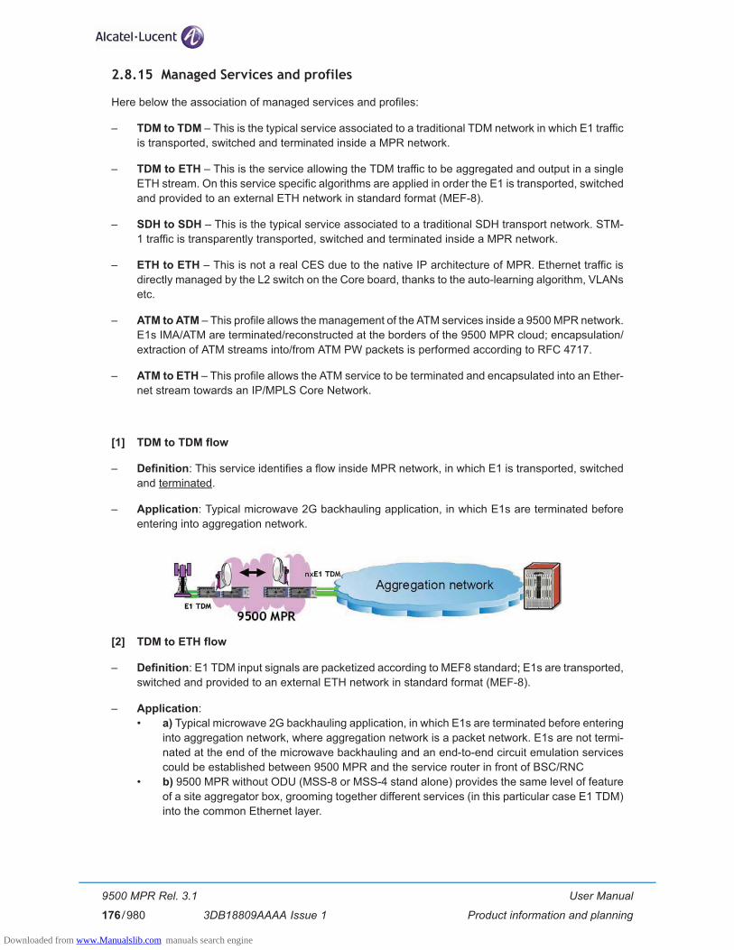
User Manual
Product information and planning
9500 MPR Rel. 3.1
3DB18809AAAA Issue 1176/980
2.8.15 Managed Services and profiles
Here below the association of managed services and profiles:
– TDM to TDM – This is the typical service associated to a traditional TDM network in which E1 traffic is transported, switched and terminated inside a MPR network.
– TDM to ETH – This is the service allowing the TDM traffic to be aggregated and output in a single ETH stream. On this service specific algorithms are applied in order the E1 is transported, switched and provided to an external ETH network in standard format (MEF-8).
– SDH to SDH – This is the typical service associated to a traditional SDH transport network. STM-1 traffic is transparently transported, switched and terminated inside a MPR network.
– ETH to ETH – This is not a real CES due to the native IP architecture of MPR. Ethernet traffic is directly managed by the L2 switch on the Core board, thanks to the auto-learning algorithm, VLANs etc.
– ATM to ATM – This profile allows the management of the ATM services inside a 9500 MPR network. E1s IMA/ATM are terminated/reconstructed at the borders of the 9500 MPR cloud; encapsulation/extraction of ATM streams into/from ATM PW packets is performed according to RFC 4717.
– ATM to ETH – This profile allows the ATM service to be terminated and encapsulated into an Ether-net stream towards an IP/MPLS Core Network.
[1] TDM to TDM flow
– Definition: This service identifies a flow inside MPR network, in which E1 is transported, switched and terminated.
– Application: Typical microwave 2G backhauling application, in which E1s are terminated before entering into aggregation network.
[2] TDM to ETH flow
– Definition: E1 TDM input signals are packetized according to MEF8 standard; E1s are transported, switched and provided to an external ETH network in standard format (MEF-8).
– Application: • a) Typical microwave 2G backhauling application, in which E1s are terminated before entering
into aggregation network, where aggregation network is a packet network. E1s are not termi-nated at the end of the microwave backhauling and an end-to-end circuit emulation services could be established between 9500 MPR and the service router in front of BSC/RNC
• b) 9500 MPR without ODU (MSS-8 or MSS-4 stand alone) provides the same level of feature of a site aggregator box, grooming together different services (in this particular case E1 TDM) into the common Ethernet layer.
Downloaded from www.Manualslib.com manuals search engine
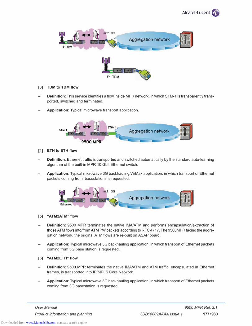
User Manual
Product information and planning
9500 MPR Rel. 3.1
3DB18809AAAA Issue 1 177/980
[3] TDM to TDM flow
– Definition: This service identifies a flow inside MPR network, in which STM-1 is transparently trans-ported, switched and terminated.
– Application: Typical microwave transport application.
[4] ETH to ETH flow
– Definition: Ethernet traffic is transported and switched automatically by the standard auto-learning algorithm of the built-in MPR 10 Gbit Ethernet switch.
– Application: Typical microwave 3G backhauling/WiMax application, in which transport of Ethernet packets coming from basestations is requested.
[5] “ATM2ATM” flow
– Definition: 9500 MPR terminates the native IMA/ATM and performs encapsulation/extraction of those ATM flows into/from ATM PW packets according to RFC 4717. The 9500MPR facing the aggre-gation network, the original ATM flows are re-built on ASAP board.
– Application: Typical microwave 3G backhauling application, in which transport of Ethernet packets coming from 3G base station is requested.
[6] “ATM2ETH” flow
– Definition: 9500 MPR terminates the native IMA/ATM and ATM traffic, encapsulated in Ethernet frames, is transported into IP/MPLS Core Network.
– Application: Typical microwave 3G backhauling application, in which transport of Ethernet packets coming from 3G basestation is requested.
Downloaded from www.Manualslib.com manuals search engine
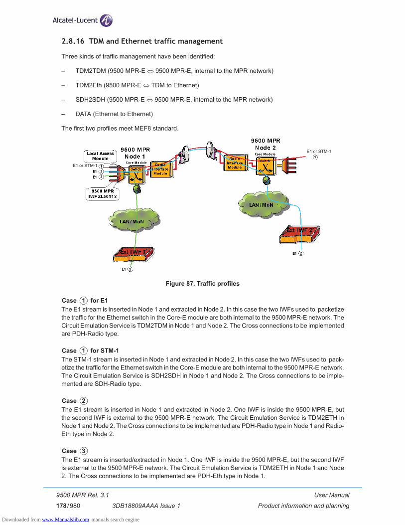
User Manual
Product information and planning
9500 MPR Rel. 3.1
3DB18809AAAA Issue 1178/980
2.8.16 TDM and Ethernet traffic management
Three kinds of traffic management have been identified:
– TDM2TDM (9500 MPR-E � 9500 MPR-E, internal to the MPR network)
– TDM2Eth (9500 MPR-E � TDM to Ethernet)
– SDH2SDH (9500 MPR-E � 9500 MPR-E, internal to the MPR network)
– DATA (Ethernet to Ethernet)
The first two profiles meet MEF8 standard.
Figure 87. Traffic profiles
The E1 stream is inserted in Node 1 and extracted in Node 2. In this case the two IWFs used to packetize the traffic for the Ethernet switch in the Core-E module are both internal to the 9500 MPR-E network. The Circuit Emulation Service is TDM2TDM in Node 1 and Node 2. The Cross connections to be implemented are PDH-Radio type.
The STM-1 stream is inserted in Node 1 and extracted in Node 2. In this case the two IWFs used to pack-etize the traffic for the Ethernet switch in the Core-E module are both internal to the 9500 MPR-E network. The Circuit Emulation Service is SDH2SDH in Node 1 and Node 2. The Cross connections to be imple-mented are SDH-Radio type.
The E1 stream is inserted in Node 1 and extracted in Node 2. One IWF is inside the 9500 MPR-E, but the second IWF is external to the 9500 MPR-E network. The Circuit Emulation Service is TDM2ETH in Node 1 and Node 2. The Cross connections to be implemented are PDH-Radio type in Node 1 and Radio-Eth type in Node 2.
The E1 stream is inserted/extracted in Node 1. One IWF is inside the 9500 MPR-E, but the second IWF is external to the 9500 MPR-E network. The Circuit Emulation Service is TDM2ETH in Node 1 and Node 2. The Cross connections to be implemented are PDH-Eth type in Node 1.
E1 or STM-1
E1 or STM-1
Case 1 for E1
Case 1 for STM-1
Case 2
Case 3
Downloaded from www.Manualslib.com manuals search engine

User Manual
Product information and planning
9500 MPR Rel. 3.1
3DB18809AAAA Issue 1 179/980
Figure 88. Traffic profiles
In these cases Ethernet packets enter Node 1 and are extracted in Node 2. In case 4 the Ethernet packets encapsulate the E1 stream; in case 5 the packets are native Ethernet packets. None of the IWFs belongs to the 9500 MPR-E network. The Circuit Emulation Service is ETH2ETH in Node 1 and Node 2. No Cross connections must be implemented. The path is automatically implemented with the standard auto-learning algorithm of the 9500 MPR-E Ethernet switch.
Case 4 and 5
Downloaded from www.Manualslib.com manuals search engine
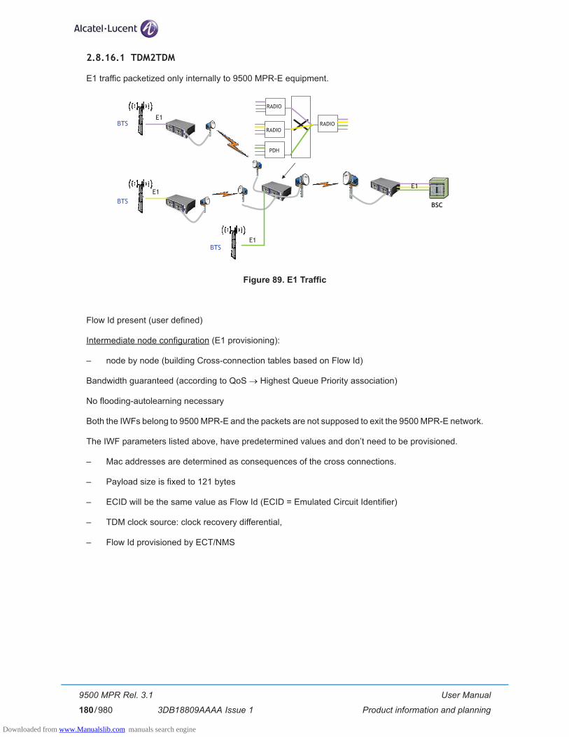
User Manual
Product information and planning
9500 MPR Rel. 3.1
3DB18809AAAA Issue 1180/980
2.8.16.1 TDM2TDM
E1 traffic packetized only internally to 9500 MPR-E equipment.
Figure 89. E1 Traffic
Flow Id present (user defined)
Intermediate node configuration (E1 provisioning):
– node by node (building Cross-connection tables based on Flow Id)
Bandwidth guaranteed (according to QoS � Highest Queue Priority association)
No flooding-autolearning necessary
Both the IWFs belong to 9500 MPR-E and the packets are not supposed to exit the 9500 MPR-E network.
The IWF parameters listed above, have predetermined values and don’t need to be provisioned.
– Mac addresses are determined as consequences of the cross connections.
– Payload size is fixed to 121 bytes
– ECID will be the same value as Flow Id (ECID = Emulated Circuit Identifier)
– TDM clock source: clock recovery differential,
– Flow Id provisioned by ECT/NMS
E1
BSC
PDH
RADIORADIO
RADIO
BTS
E1
BTSE1
BTSE1
Downloaded from www.Manualslib.com manuals search engine

User Manual
Product information and planning
9500 MPR Rel. 3.1
3DB18809AAAA Issue 1 181/980
2.8.16.2 TDM2Eth
E1 traffic both internal and external to 9500 MPR-E equipment.
Figure 90. E1 Traffic
Flow Id present (user defined)
All the parameters must be configured compliant with the MEF8 standard
Adaptive or differential clock recovery supported
Bandwidth guaranteed (according to QoS � Highest Queue Priority association)
Destination MAC added before going into whole network (MEF8 compliant)
Only one of the IWFs belongs to 9500 MPR-E and the packets are supposed to exit the 9500 MPR-E network.
– MAC addresses: in all involved nodes are determined as consequences of the cross connections; the only exception is the Ethernet Terminal Node (the node where the TDM2ETH traffic goes through an user Ethernet port). In such ETN the source address is the node Mac address, the destination Mac address will be provisioned by ECT/NMS.
– Payload size: is fixed to 256 bytes
– ECID: provisioned by ECT/NMS, 2 different values may be used for each direction (ECID = Emulated Circuit Identifier)
– TDM clock source is provisioned by ECT/NMS: clock recovery adaptive, clock recovery differential, clock loopback (TDM line in)
– Flow Id is provisioned by ECT/NMS (One Vlan is assigned to each bi-directional circuit emulated E1 flow)
For this case the expected latency for 1 hop is 3.5 msec for 256 bytes.
E1
BSC
E1EthEth
PSNPSN
BTS
BTS
BTSE1
E1
Downloaded from www.Manualslib.com manuals search engine
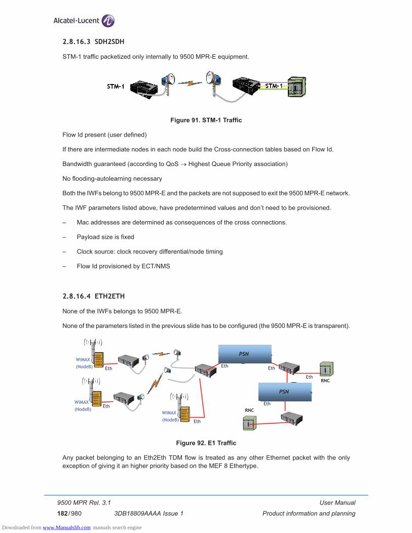
User Manual
Product information and planning
9500 MPR Rel. 3.1
3DB18809AAAA Issue 1182/980
2.8.16.3 SDH2SDH
STM-1 traffic packetized only internally to 9500 MPR-E equipment.
Figure 91. STM-1 Traffic
Flow Id present (user defined)
If there are intermediate nodes in each node build the Cross-connection tables based on Flow Id.
Bandwidth guaranteed (according to QoS � Highest Queue Priority association)
No flooding-autolearning necessary
Both the IWFs belong to 9500 MPR-E and the packets are not supposed to exit the 9500 MPR-E network.
The IWF parameters listed above, have predetermined values and don’t need to be provisioned.
– Mac addresses are determined as consequences of the cross connections.
– Payload size is fixed
– Clock source: clock recovery differential/node timing
– Flow Id provisioned by ECT/NMS
2.8.16.4 ETH2ETH
None of the IWFs belongs to 9500 MPR-E.
None of the parameters listed in the previous slide has to be configured (the 9500 MPR-E is transparent).
Figure 92. E1 Traffic
Any packet belonging to an Eth2Eth TDM flow is treated as any other Ethernet packet with the only exception of giving it an higher priority based on the MEF 8 Ethertype.
Eth
Eth
RNCEth
Eth
WiMAX(NodeB)
WiMAX(NodeB)
WiMAX(NodeB)
EthEth
EthRNC
PSNPSN
PSNPSN
Downloaded from www.Manualslib.com manuals search engine
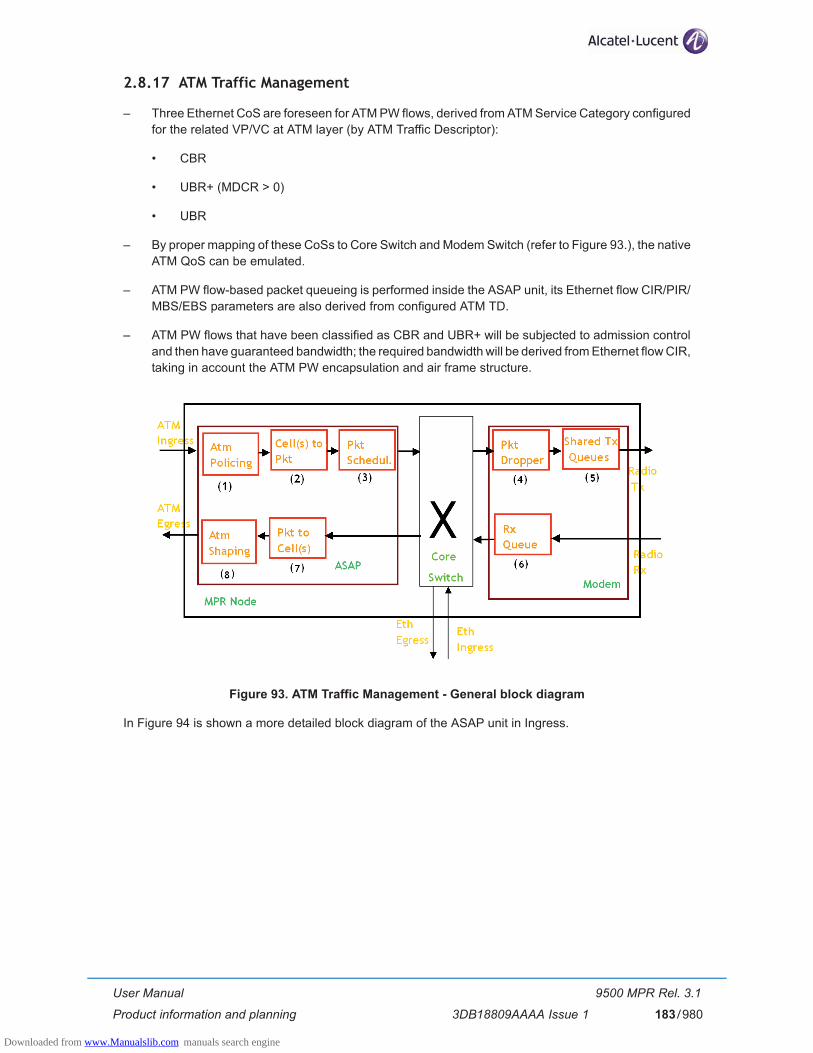
User Manual
Product information and planning
9500 MPR Rel. 3.1
3DB18809AAAA Issue 1 183/980
2.8.17 ATM Traffic Management
– Three Ethernet CoS are foreseen for ATM PW flows, derived from ATM Service Category configured for the related VP/VC at ATM layer (by ATM Traffic Descriptor):
• CBR
• UBR+ (MDCR > 0)
• UBR
– By proper mapping of these CoSs to Core Switch and Modem Switch (refer to Figure 93.), the native ATM QoS can be emulated.
– ATM PW flow-based packet queueing is performed inside the ASAP unit, its Ethernet flow CIR/PIR/MBS/EBS parameters are also derived from configured ATM TD.
– ATM PW flows that have been classified as CBR and UBR+ will be subjected to admission control and then have guaranteed bandwidth; the required bandwidth will be derived from Ethernet flow CIR, taking in account the ATM PW encapsulation and air frame structure.
Figure 93. ATM Traffic Management - General block diagram
In Figure 94 is shown a more detailed block diagram of the ASAP unit in Ingress.
Downloaded from www.Manualslib.com manuals search engine

User Manual
Product information and planning
9500 MPR Rel. 3.1
3DB18809AAAA Issue 1184/980
Figure 94. Block diagram for ATM Ingress (ATM -> Packet) direction
[1] ATM Ingress Policing• ATM Policing (cell-based) can be enabled/disabled, on provisioning base, for each VP/VC con-
figured on ATM interface, according to its Ingress Traffic Descriptor (PCR,SCR,CDVT,MCDR) as defined by ATM Traffic Management AF-TM-0121.000– Service Category: CBR, UBR+ and UBR– Conformace Definition: CBR.1
[2] Cells to packet
The ATM cells are encapsulated in PWE3 packet.
[3] Packet Profiled Scheduling• ATM cell(s) are put into a packet, as result of provisioned value of max concat. number or
elapsed timeout; an Ethernet flow is therefore created (identified by ATM PW Label/VLAN pair), whose CoS and CIR/PIR are automatically assigned by MPR based on ATM Ingress Traffic Descriptor and previous encaps params.
• This packet is then put in a dedicated queue where:– it is scheduled for transmission towards Core switch, with a constant rate given by
assigned CIR/PIR (depending on CoS):• if the actual flow rate is < CIR:
– 802.1p bits are marked as "GREEN", if CIR<actual flow rate<PIR, – 802.1p bits are marked as "YELLOW", (the packet is descarded on the Modem
unit in case of congestion on radio i/f);• if the actual flow rate is > PIR, congestion on this queue happens and the next PWE3
packets will be dropped directly in ASAP card.
In/out profile is a dynamic assignment, based on CIR/PIR conformance for packet queue, and FC type (expedited vs best effort). The mapping of the 802.1p bits is shown in Table 31.
It is mapped to 802.1p bits in the following manner:
Downloaded from www.Manualslib.com manuals search engine

User Manual
Product information and planning
9500 MPR Rel. 3.1
3DB18809AAAA Issue 1 185/980
Table 31. 802.1p mapping
[4] Packet Dropper
The packets marked with yellow are discarded in case of congestion, when the buffer in the Modem unit exceed a specific threshold.
Dropping mechanism:• if a configurable queue fill level is overcame, then ATM PW packets that have been marked by
ASAP as out of profile (within 802.1p bits) are discarded.
The dropping mechanism applyies to queues with guaranteed Traffic:• It applies to queue 7 and 6.• To avoid delay on queue 7, shared among TDM2ETH, ATM CBR, the fill level to start descarding
is configured according to max acceptable delay (about 1 ms).
[5] Shared Tx queues
The packet according to its service category is send to one of the output queues.
[6] Rx Queues
Flows of the same type are reassembled in different queues.
[7] Packet to cells
The ATM cells are extracted from the PWE3 packet.
[8] ATM Egress Shaping• A four-queue scheduling is used for for ATM traffic egressing MPR system. • The higher priority queues are reserved for ATM shaped traffic, while the lowest one is reserved
to not shaped traffic. • Cell-based ATM Shaping is applied for a VP/VC that has been configured with CBR and VBR
Service Category on the basis of its configured egress ATM Traffic Descriptor, general refer-ence for this feature is ATM standards.
• A Weighted Round Robin is instead applied for all VPs/VCs that are not shaped. The weights are based on the value of configured MDCR in the egress ATM Traffic Descriptor value accord-ing to below table:
802.1p bits Usage Color
000 Best Effort, Out-of-Profile YELLOW
001 unused -
010 Expedited, Out-of-Profile YELLOW
011 unused -
100 Best Effort, In-Profile GREEN
101 unused -
110 Expedited, In-Profile GREEN
111 Contro - egress only -
Downloaded from www.Manualslib.com manuals search engine

User Manual
Product information and planning
9500 MPR Rel. 3.1
3DB18809AAAA Issue 1186/980
e.g. MDCR = 1000 [cell/s] -> Weight = 4An UBR has MDCR=0 -> weight = 1
Table 32. RR weights
N.B. ATM “Light” ServiceWith MPT-HC or MPT-MC there is no full support of ATM Traffic as with ODU300, but the so-called ATM “Light” Service applies.In this release, ATM PW traffic will be transported as native Ethernet traffic over radio directions with MPT ODU. Radio QoS applied to ATM PW traffic will be the one for native Ethernet traffic, but since band-width cannot be guaranteed, admission control will not be applied. Transport of ATM PW traffic within an MPR network must be done with radio links using all the same type of ODU, either ODU300 or MPT ODU. To avoid NE reconfiguration in migration towards future release fully supporting ATM PW Ser-vice on radio directions with MPT ODU, a complete provisioning is applied since this release (including declaration of traffic descriptors). However, configurations where ATM PW flows are cross-connected between a Radio-Ethernet terminal and an ATM-Ethernet terminal will require NE reconfiguration, as different MAC Address need to be provisioned.
MDCR [cell/s] RR Weight
<= 149 1
<= 300 2
<= 602 3
<= 1206 4
<= 2413 5
<= 3621 6
<= 4529 7
>= 4530 8
Downloaded from www.Manualslib.com manuals search engine
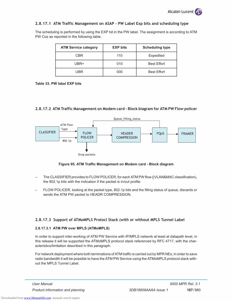
User Manual
Product information and planning
9500 MPR Rel. 3.1
3DB18809AAAA Issue 1 187/980
2.8.17.1 ATM Traffic Management on ASAP - PW Label Exp bits and scheduling type
The scheduling is performed by using the EXP bit in the PW label. The assignment is according to ATM PW Cos as reported in the following table.
Table 33. PW label EXP bits
2.8.17.2 ATM Traffic Management on Modem card - Block biagram for ATM PW Flow policer
Figure 95. ATM Traffic Management on Modem card - Block diagram
– The CLASSIFIER provides to FLOW POLICER, for each ATM PW flow ((VLAN&MAC classification), the 802.1p bits with the indication if the packet is in/out profile.
– FLOW POLICER, looking at the packet type, 802.1p bits and the filling status of queue, discards or sends the ATM PW packet to HEADR COMPRESSION.
2.8.17.3 Support of ATMoMPLS Protocl Stack (with or without MPLS Tunnel Label
2.8.17.3.1 ATM PW over MPLS (ATMoMPLS)
In order to support inter-working of ATM PW Service with IP/MPLS network at least at datapath level, in this release it will be supported the ATMoMPLS protocol stack referenced by RFC 4717, with the char-acteristics/limitation described in this paragraph.
For network deployment where both terminations of ATM traffic is carried out by MPR NEs, in order to save radio bandwidth it will be possible to have the ATM PW Service using the ATMoMPLS protocol stack with-out the MPLS Tunnel Label.
ATM Service category EXP bits Scheduling type
CBR 110 Expedited
UBR+ 010 Best Effort
UBR 000 Best Effort
Drop packets
FLOWPOLICER
CLASSIFIER HEADERCOMPRESSION
FQoS FRAMER
Queue_filling_status
ATM FlowType
802.1p
Downloaded from www.Manualslib.com manuals search engine

User Manual
Product information and planning
9500 MPR Rel. 3.1
3DB18809AAAA Issue 1188/980
2.8.17.3.2 Protocol Stack Termination
In this release the ATMoMPLS protocol stack is terminated directly by the MPR NE where native ATM interface is present (i.e. MPLS Tunnel Label, if present, is added by ASAP Card).
That implies all MPR NEs must be aware of MPLS Tunnel Label presence, i.e. to apply ATM PW Header Compression.
2.8.17.3.3 802.1q VLAN Tag
ATMoMPLS protocol stack used by MPR foresees to have the 802.1q VLAN Tag.
VLAN is used, within MPR network, to define for ATM PW frames:
– forwarding plane
– colour marking consequent to profiled scheduling
– specific processing (ATM PW Header Compression) and QoS (queue assignment and colour-based policing) on radio interfaces
The same VLAN ID can be used by several ATM PW flows only if they share the same CoS and forwarding plane. Thinking to future releases, to use the same VLAN ID, the ATM PW flows must also share the same encapsulation format (i.e. N-1 cell mode with or without Control Word, AAL5 SDU or PDU modes)
A VLAN ID that is used by ATM PW flow(s) can never be used for TDM flows.
The fields of the 802.1Q VLAN Tag to be inserted into ATM PW flow frames are assigned in the following manner:
– 12-bit VLAN ID will be provisioned by ECT/NMS
– 3-bit PCP field is assigned according to the ATM PW flow COS and packet profiled scheduling
– 1-bit CFI field is set to 0
2.8.17.3.4 VLAN Swap
VLAN Swap feature is foreseen on "hand-off" MPR NE, i.e. the NE connected to IP/MPLS network.
VLAN Swap means that ATM PW flows ingressing/egressing the "hand-off" MPR will have the same com-mon "external" VLAN ID, while within MPR network each ATM PW flow will use its own "internal" VLAN ID (may be shared among several ATM PW flows with same path and CoS).
To avoid possible configuration clashing, the above "external" VLAN ID should belong to the allowed range. Moreover, the "external" VLAN ID should be different from each "internal" VLAN ID.
VLAN Swap performed by the "hand-off" MPR NE is based on:
– for ingress, IP/MPLS network -> MPR network direction: the Inbound PW Label value
– for egress, MPR network -> IP/MPLS network direction: ATM PW CoS (to reduce numbers of "rules" used for such mapping).
Downloaded from www.Manualslib.com manuals search engine

User Manual
Product information and planning
9500 MPR Rel. 3.1
3DB18809AAAA Issue 1 189/980
2.8.17.3.5 802.1p remarking
In addition to VLAN Swap, 802.1p bits remarking are also applied by "hand-off" MPR NE to ATM PW frames:
– for ingress, IP/MPLS network -> MPR network direction: all frames will be declared as "green"
– for egress, MPR network -> IP/MPLS network direction: 802.1p bits will copy ATM PW Exp Bits
2.8.17.3.6 Tunnel Label
The MPLS Tunnel Label for ATM PW frames is foreseen only for compatibility with ATMoMPLS protocol stack.
MPR network is actually not using information from MPLS Tunnel Label value in ATM PW frames, for example:
– forwarding is based on VLAN/MAC DA
– CoS assignment of such frames will be always based on PW Label Exp bits
Tunnel Label fields to be inserted into ATM PW frames generated by MPR are assigned as below reported:
– 20-bit Tunnel Label will be provisioned by ECT/NMS
– EXP bits are copied from PW Label Exp bits
– BoS bit is set to 0
– TTL field is set to 255
Downloaded from www.Manualslib.com manuals search engine

User Manual
Product information and planning
9500 MPR Rel. 3.1
3DB18809AAAA Issue 1190/980
2.8.18 Ethernet Traffic Management
The Ethernet traffic is all the traffic entered the MPR network from user Ethernet ports.
By ECT/NMS it is possible to define the way to manage the Ethernet traffic according to one of the following options:
– 802.1D (MAC Address bridge)
– 802.1Q (Virtual Bridge).
2.8.18.1 Bridge type change
In case of change of the bridge type from 802.1Q to 802.1D, the content of the VLAN table and the VLAN assigned to the user Ethernet ports (refer to par. 2.8.18.2) has to be deleted by the Operator before to change the bridge type.
2.8.18.2 Reserved Multicast Addresses
The following table summarizes the actions taken for specific reserved multicast addresses. Frames identified with these destination addresses are handled uniquely since they are designed for Layer 2 Control Protocols.
The actions taken by the system can be:
– Discard - The system discards all ingress Ethernet frames and must not generate any egress Ether-net Frame carrying the reserved multicast address.
– Forward - The system accepts all ingress Ethernet frames as standard multicast frames and for-wards them accordingly.
– Peer - The system acts as a peer of the connected device in the operation of the relevant Layer 2 Control Protocol.
Reserved Multicast Address
Function Action
01-80-C2-00-00-00 Bridge Group Address Forward
01-80-C2-00-00-01 Clause 31 (MAC Control) of IEEE 802.3 Flow-Control enabled: Peer�Flow-Control disabled: Discard
01-80-C2-00-00-02 Clause 43 (Link Aggregation) and Clause 57 (OAM) of IEEE 802.3
Peer for Link Aggregation and ESMCDiscard for QAM
01-80-C2-00-00-03 IEEE 802.1X PAE address Discard
01-80-C2-00-00-04 - �01-80-C2-00-00-0D
Reserved for future standardization Discard
01-80-C2-00-00-0E IEEE 802.1AB LLDP multicast address Discard
01-80-C2-00-00-0F Reserved for future standardization Discard
Downloaded from www.Manualslib.com manuals search engine

User Manual
Product information and planning
9500 MPR Rel. 3.1
3DB18809AAAA Issue 1 191/980
01-80-C2-00-00-10 All LANs Bridge Management Group Address Forward
01-80-C2-00-00-11 - �01-80-C2-00-00-1F
Reserved Forward
01-80-C2-00-00-20 GMRP Address (Clause 10 of IEEE 802.1D) Forward
01-80-C2-00-00-21 GVRP Address (IEEE 802.1Q) Forward
01-80-C2-00-00-22 - �01-80-C2-00-00-2F
Reserved for GARP Application Forward
01-80-C2-00-00-30 - �01-80-C2-00-00-3F
CCM and LTM Group Destination MAC Addresses (IEEE 802.1ag)
Peer/Forward
Reserved Multicast Address
Function Action
Downloaded from www.Manualslib.com manuals search engine

User Manual
Product information and planning
9500 MPR Rel. 3.1
3DB18809AAAA Issue 1192/980
2.8.19 LAG (Link Aggregation Group)
2.8.19.1 LAG overview
Link Aggregation groups a set of ports so that two network nodes can be interconnected using multiple links to increase link capacity and availability between them.
When aggregated, two or more physical links operate as a single logical link with a traffic capacity that is the sum of the individual link capacities.
This doubling, tripling or quadrupling of capacity is relevant where more capacity is required than can be provided on one physical link.
Link aggregation also provides redundancy between the aggregated links. If a link fails, its traffic is redi-rected onto the remaining link, or links.
If the remaining link or links do not have the capacity needed to avoid a traffic bottleneck, appropriate QoS settings are used to prioritize traffic so that all high priority traffic continues to get through.
The Link Aggregation is performed according to 802.3ad and can be applied to Radio ports and to User Ethernet ports.
2.8.19.1.1 Link aggregation on Radio ports (Radio LAG)
Link aggregation can be applied to radio ports (in this case it is named Radio Link Aggregation).
Figure 96. Radio LAG overview
In this example, user traffic is split up into radio channels. Main advantages:
– Throughput. The overall radio Ethernet throughput is more than 1 Gbit/sec (4 x 350 Mbit/s, being this the value for 256QAM@56 MHz)
– Protection. In case of a failure of one of the three channels, all the traffic is redirected on the remain-ing link (with a throughput of around 0.35 Gbit/sec). The discarded or dropped traffic is the one with lower priority: high priority traffic is still running on the remaining active channels.
Downloaded from www.Manualslib.com manuals search engine
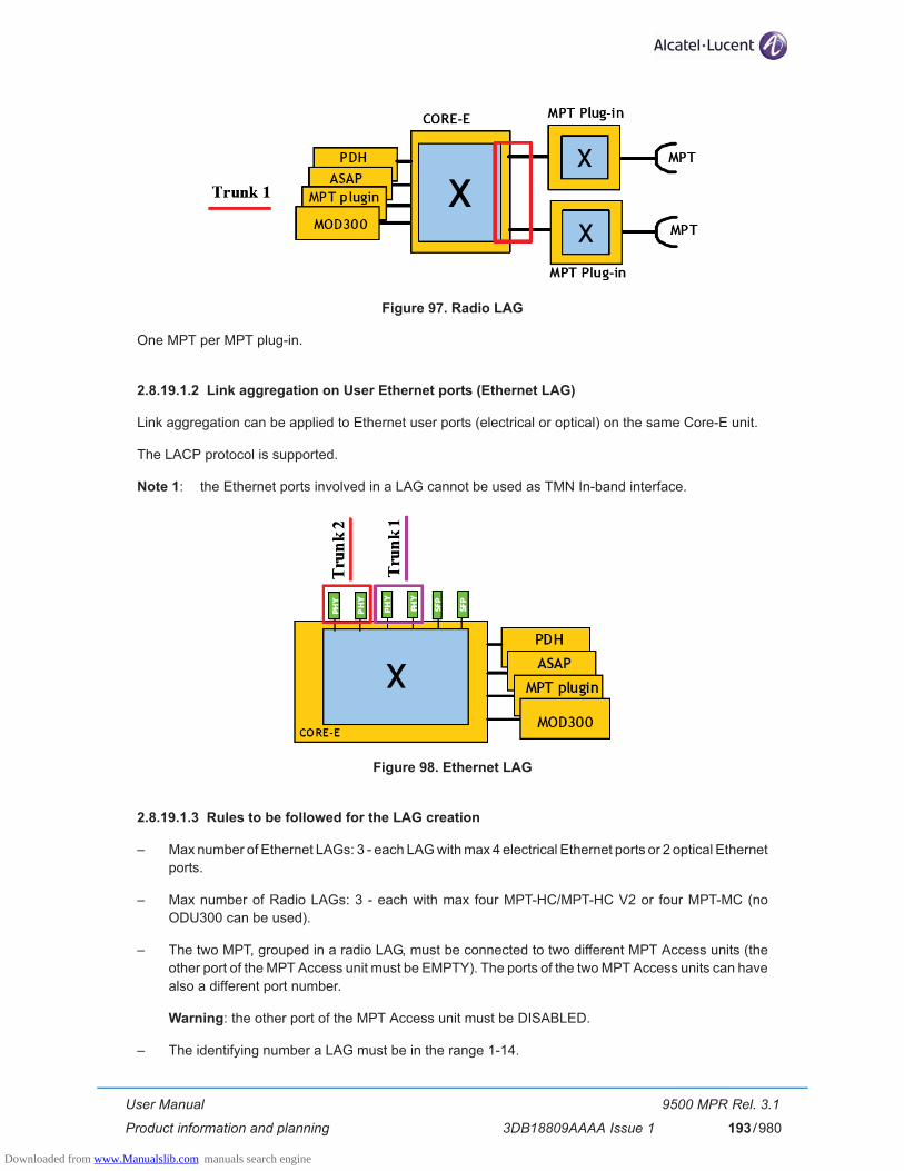
User Manual
Product information and planning
9500 MPR Rel. 3.1
3DB18809AAAA Issue 1 193/980
Figure 97. Radio LAG
One MPT per MPT plug-in.
2.8.19.1.2 Link aggregation on User Ethernet ports (Ethernet LAG)
Link aggregation can be applied to Ethernet user ports (electrical or optical) on the same Core-E unit.
The LACP protocol is supported.
Note 1: the Ethernet ports involved in a LAG cannot be used as TMN In-band interface.
Figure 98. Ethernet LAG
2.8.19.1.3 Rules to be followed for the LAG creation
– Max number of Ethernet LAGs: 3 - each LAG with max 4 electrical Ethernet ports or 2 optical Ethernet ports.
– Max number of Radio LAGs: 3 - each with max four MPT-HC/MPT-HC V2 or four MPT-MC (no ODU300 can be used).
– The two MPT, grouped in a radio LAG, must be connected to two different MPT Access units (the other port of the MPT Access unit must be EMPTY). The ports of the two MPT Access units can have also a different port number.
Warning: the other port of the MPT Access unit must be DISABLED.
– The identifying number a LAG must be in the range 1-14.
Downloaded from www.Manualslib.com manuals search engine

User Manual
Product information and planning
9500 MPR Rel. 3.1
3DB18809AAAA Issue 1194/980
2.8.20 Quality Of Services (QoS)
The QoS function inside 9500 MPR-E is the result of a distributed implementation in the switch and Radio Interface module. Both those QoS functions are properly configured in order to get the wished behavior on Ethernet flows that will be transmitted towards the Radio.
N.B. Configurations files
To obtain a specific behavior (not obtainable with the WebEML) the configuration files can be used. The configuration files configure the Ethernet switch inside the Core-E and the FPGA inside the Modem unit for ODU300 and inside the MPT Access unit for MPT-HC/MPT-MC.
The configuration files are written by using a set of low level commands provisioning in the proper way different devices of different MPR cards. After an NE reset, the configuration file is applied, provisioning the Ethernet switch and other devices to implement the desired feature.
The configuration file must be put in the compact flash plugged in Main Core, inside a specific directory, via FTP.
The application of a new configuration file could cause traffic hits.
The use of the Configuration files is explained in the relevant document “Configuration File Management”.
2.8.20.1 QoS in the Core-E unit
Figure 99. QoS in the Core-E unit
The figure shows an overview of the QoS implementation inside the switch.
The Quality of Service feature of the Ethernet switch provides four internal queues per port to support four different traffic priorities. Typically the high-priority traffic experiences less delay than that low-priority in the switch under congested conditions.
For each egress port according to method of QoS classification configured in the switch, the packets are assigned to each queue.
Downloaded from www.Manualslib.com manuals search engine
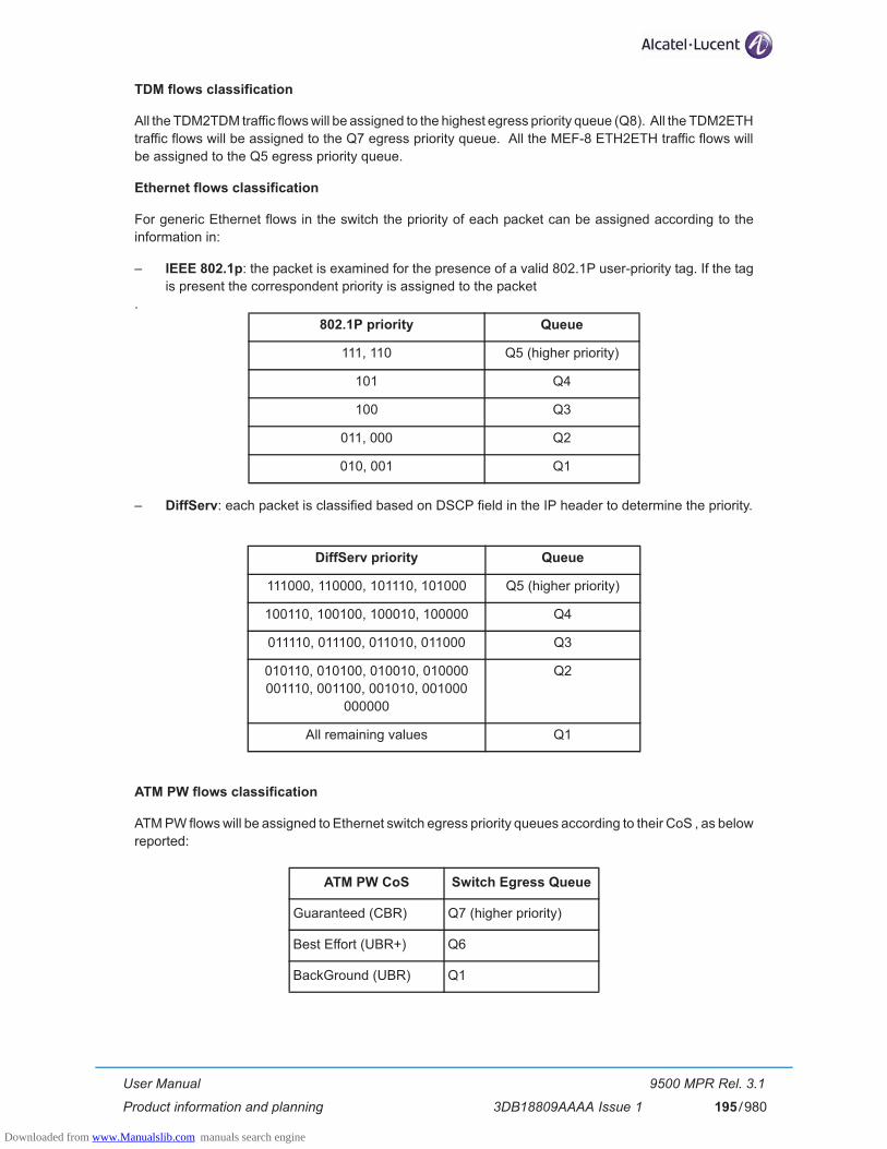
User Manual
Product information and planning
9500 MPR Rel. 3.1
3DB18809AAAA Issue 1 195/980
TDM flows classification
All the TDM2TDM traffic flows will be assigned to the highest egress priority queue (Q8). All the TDM2ETH traffic flows will be assigned to the Q7 egress priority queue. All the MEF-8 ETH2ETH traffic flows will be assigned to the Q5 egress priority queue.
Ethernet flows classification
For generic Ethernet flows in the switch the priority of each packet can be assigned according to the information in:
– IEEE 802.1p: the packet is examined for the presence of a valid 802.1P user-priority tag. If the tag is present the correspondent priority is assigned to the packet
.
– DiffServ: each packet is classified based on DSCP field in the IP header to determine the priority.
ATM PW flows classification
ATM PW flows will be assigned to Ethernet switch egress priority queues according to their CoS , as below reported:
802.1P priority Queue
111, 110 Q5 (higher priority)
101 Q4
100 Q3
011, 000 Q2
010, 001 Q1
DiffServ priority Queue
111000, 110000, 101110, 101000 Q5 (higher priority)
100110, 100100, 100010, 100000 Q4
011110, 011100, 011010, 011000 Q3
010110, 010100, 010010, 010000001110, 001100, 001010, 001000
000000
Q2
All remaining values Q1
ATM PW CoS Switch Egress Queue
Guaranteed (CBR) Q7 (higher priority)
Best Effort (UBR+) Q6
BackGround (UBR) Q1
Downloaded from www.Manualslib.com manuals search engine

User Manual
Product information and planning
9500 MPR Rel. 3.1
3DB18809AAAA Issue 1196/980
Scheduler
The scheduler algorithm cannot be configured. HQP scheduler algorithm is used on queues Q8, Q7 and Q6.
Deficit Weighted Round Robin (DWRR) is used on the other queues with the following weights:
QoS with jumbo frame
While there is no physical limitation to the number of ports that can receive jumbo frame, if more jumbo flows are transmitted toward the same port into two different queues the QoS could work in wrong way. It is recommended to forward jumbo frame only in the queue Q1 (lower priority).
2.8.20.2 QoS in the Modem unit
Figure 100. QoS in the Modem unit
In the figure is shown an overview of the QoS implementation inside the Modem unit which is used to interface the ODU300.
The QoS feature provides eight internal queues to support different traffic priorities. The QoS function can assign the packet to one of the eight egress transmit queues.
– Queue 8 is assigned to TDM2TDM traffic
– Queue 7 is assigned to TDM2Eth traffic
– Queue 6 is assigned to TMN
QUEUE WEIGHT
Q5 (higher priority) 16
Q4 8
Q3 4
Q2 2
Q1 1
Downloaded from www.Manualslib.com manuals search engine

User Manual
Product information and planning
9500 MPR Rel. 3.1
3DB18809AAAA Issue 1 197/980
Queues 1 to 4 are assigned to Ethernet traffic according to the information inside the packet as 802.1p field, DiffServ field, Ethertype or 802.1Q VLAN_ID.
TDM flows classification
All the TDM2TDM traffic flows are assigned to the highest egress priority queue (Q8). All the TDM2ETH traffic flows are assigned to the Q7 egress priority queue. All the MEF-8 ETH2ETH traffic flows are assigned to the Q5 egress priority queue.
TMN flows classification
All TMN traffic flows are assigned to the Q6 egress priority queue.
QoS based on IEEE std. 802.1p
When 802.1p QoS mechanism is adopted, the reference is the standard “IEEE 802.1D-2004 Annex G User priorities and traffic classes” that defines 7 traffic types and the corresponding user priority values.
Considering that in the Radio Interface module for generic Ethernet traffic there are five egress queues the mapping 802.1p value to queue is the following:
QoS based on DiffServ
802.1p priority Queue
111, 110 Q5 (higher priority)
101 Q4
100 Q3
011, 000 Q2
010, 001 Q1
DiffServ priority Queue
111000, 110000, 101110, 101000 Q5 (higher priority)
100110, 100100, 100010, 100000 Q4
011110, 011100, 011010, 011000 Q3
010110, 010100, 010010, 010000001010, 001100, 001010, 001000, 000000
Q2
All remaining values Q1
Downloaded from www.Manualslib.com manuals search engine
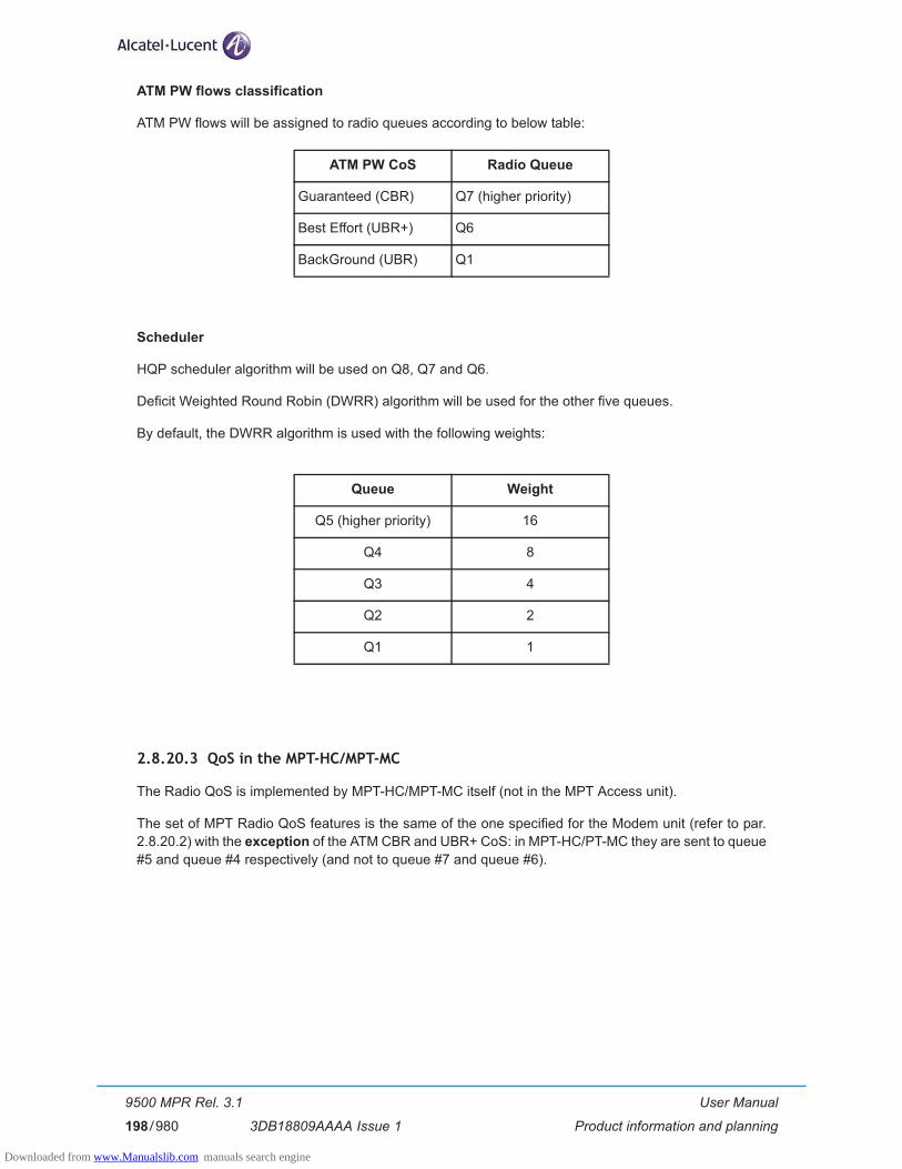
User Manual
Product information and planning
9500 MPR Rel. 3.1
3DB18809AAAA Issue 1198/980
ATM PW flows classification
ATM PW flows will be assigned to radio queues according to below table:
Scheduler
HQP scheduler algorithm will be used on Q8, Q7 and Q6.
Deficit Weighted Round Robin (DWRR) algorithm will be used for the other five queues.
By default, the DWRR algorithm is used with the following weights:
2.8.20.3 QoS in the MPT-HC/MPT-MC
The Radio QoS is implemented by MPT-HC/MPT-MC itself (not in the MPT Access unit).
The set of MPT Radio QoS features is the same of the one specified for the Modem unit (refer to par. 2.8.20.2) with the exception of the ATM CBR and UBR+ CoS: in MPT-HC/PT-MC they are sent to queue #5 and queue #4 respectively (and not to queue #7 and queue #6).
ATM PW CoS Radio Queue
Guaranteed (CBR) Q7 (higher priority)
Best Effort (UBR+) Q6
BackGround (UBR) Q1
Queue Weight
Q5 (higher priority) 16
Q4 8
Q3 4
Q2 2
Q1 1
Downloaded from www.Manualslib.com manuals search engine
Related Documents
![3 KEPIC의 현황과 적용 [호환 모드]20KEPIC%C... · mpt 2 asme ptc 2용어정의와상수 mpt 4.2asme ptc 4.2 미분기 mpt 4.3asme ptc 4.3 공기예열기 mpt 12.3asme ptc](https://static.cupdf.com/doc/110x72/5aac75367f8b9a693f8d1890/3-kepic-20kepiccmpt-2-asme-ptc-2.jpg)
![MASTER OF PHYSIOTHERAPY [MPT] (2012-2013)/Medical/MPT... · 3 MASTER OF PHYSIOTHERAPY [MPT] FRAMEWORK MPT-I MPT-II Exam Papers Paper- I: Applied Basic Sciences Paper-V: Elective:](https://static.cupdf.com/doc/110x72/5aa8bb437f8b9a9a188bf59c/master-of-physiotherapy-mpt-2012-2013medicalmpt3-master-of-physiotherapy.jpg)