Siemens Building Siemens Building Siemens Building Siemens Building Siemens Building Tec ec ec ec echnologies hnologies hnologies hnologies hnologies Fire S Fire S Fire S Fire S Fire Safety afety afety afety afety P/N 315-033744-3 Installation, Operation and Maintenance Manual FIREFINDER-XLS CONTROL PANEL

Welcome message from author
This document is posted to help you gain knowledge. Please leave a comment to let me know what you think about it! Share it to your friends and learn new things together.
Transcript
Siemens Building Siemens Building Siemens Building Siemens Building Siemens Building TTTTTececececechnologieshnologieshnologieshnologieshnologiesFire SFire SFire SFire SFire SafetyafetyafetyafetyafetyP/N 315-033744-3
Installation, Operation and Maintenance Manual
FIREFINDER-XLS CONTROL PANEL
CAUTION
ALL WIRING MUST BE DONE AS DESCRIBED BELOWTO OBTAIN SAFE AND PROPER SYSTEM OPERATION.
1. Earth ground the FireFinder-XLS enclosure properly; see the latest edition of theNational Electrical Code or CAN/ULC-S524-01 Canadian Electrical Code forapproved methods. Conduit ground is NOT adequate.
2. To wire the System in compliance with NEC Article 760, refer to the PowerLimited Wiring Instructions for the CAB1 Enclosure, P/N 315-033007, or theCAB2-BB/CAB3-BB, P/N 315-033009, as applicable.
3. INSULATE ALL CABLE DRAIN WIRES from any conduit or earth groundedelectrical box, including those in the FireFinder-XLS enclosure.
4. Connect shield cable drain wire ONLY inside the FireFinder-XLS enclosure.
5. No wiring used for any of the following can run outside the building:� a DLC loop� an RS-485 network� a NAC circuit used for audibles, audio, and telephone risers� an HZM initiating device zone
For additional wiringinformation, refer to thismanual or call SiemensBuilding Technologies,Inc. Technical SupportDepartment at1-800-248-7976.
TABLE OF CONTENTS
CONTENTS i
1 DESCRIPTION ............................................................................................ 1-1
Introduction ................................................................................................ 1-1
Configuration .............................................................................................. 1-2
Basic System .............................................................................................. 1-3
Optional Modules ....................................................................................... 1-6
Voice System Modules ............................................................................... 1-9
Intelligent Analog Devices ......................................................................... 1-12
2 INSTALLATION ........................................................................................... 2-1
Introduction ................................................................................................ 2-1
Installation Guidelines ................................................................................ 2-1
3 OPERATION ............................................................................................... 3-1
Introduction ................................................................................................ 3-1
Normal Mode ............................................................................................. 3-2
Alert Mode ................................................................................................. 3-3
Report Mode .............................................................................................. 3-6
4 VOICE SYSTEM .......................................................................................... 4-1
Introduction ................................................................................................ 4-1
Equipment .................................................................................................. 4-1
Command Sations ...................................................................................... 4-1
System Operation ....................................................................................... 4-2
System Priorities ........................................................................................ 4-3
Operation Procedure .................................................................................. 4-4
ii CONTENTS
FIREFINDER-XLS INSTALLATION, OPERATION AND MAINTENANCE MANUAL | TABLE OF CONTENTS
Manual Operation ....................................................................................... 4-4
Emergency Page ................................................................................. 4-4
Evacuation .......................................................................................... 4-9
Alert .................................................................................................. 4-10
Convenience Page ............................................................................ 4-10
Background Music ............................................................................ 4-12
Speaker Groups ................................................................................ 4-13
Audible Silence/Unsilence ................................................................. 4-13
Speaker Group Non-Silence .............................................................. 4-14
Display .............................................................................................. 4-14
Audio to Local Speaker ...................................................................... 4-17
Audio Volume Control ........................................................................ 4-18
Command Station Access ................................................................. 4-20
Lamp Test .......................................................................................... 4-21
Clear Manual ..................................................................................... 4-21
Firefighters� Telephone System ................................................................. 4-21
Phone Group ..................................................................................... 4-21
Phone Page ....................................................................................... 4-22
Warden�s Page .................................................................................. 4-22
APPENDIX
A Alarm Verification ..................................................................... Appendix 1
B Application Specific Detection................................................. Appendix 3
C Intelligent Enviromnental Compensation................................. Appendix 5
D Security Point Installation ........................................................ Appendix 7
E Silent Knight Model 5129 ........................................................ Appendix 9
F Testing / Maintenance ............................................................. Appendix 11
INDEX ........................................................................................................... Index 1
1
DESCRIPTION 1-1
INTRODUCTION The Siemens Fire Safety FireFinder-XLS TM Control System is a powerful intelligent firealarm control system. FireFinder-XLS utilizes FirePrint�the most advanced firedetection technology in the world.
FireFinder-XLS is designed to provide the most reliable life safety and propertyprotection at the lowest system life cycle cost available anywhere. FireFinder-XLS hasbeen architected to be easy to install, commission and operate. The FireFinder-XLSSystem is totally modular to satisfy any size building fire alarm needs.
A basic FireFinder-XLS control system consists of the PMI operator interface andcentral processor, a PSC-12 power supply and battery charger, a PTB power termina-tion board, a DLC intelligent device loop controller, and ZIC-4A zone indicating card.This basic two loop system can monitor up to 252 intelligent detectors and devicesand provides up to 12 Amps of 24VDC power for use in driving the basic 4 notifica-tion appliance circuits. These supervised notification appliance circuits can be soft-ware configured for a wide variety of functions� such as standard NAC operation(bells, horns, chimes), strobes (synchronized or non- synchronized), coded audibles(Temporal Code 3, Marchtime, Zone Coded, etc), Municipal Tie, Leased Line, Extin-guishing agent releasing (FM-200 or Halon) or sprinkler pre-action and deluge applica-tions. The PMI�s large easy-to-read ¼ VGA display simplifies system operator control.
By adding intelligent loop controller cards, FireFinder-XLS can be expanded to supportup to 2500 intelligent detectors and devices spread across a flexible number of DLCloops. The system can also be expanded by adding additional CC-5 cardcages andpower supplies to support conventional Form C relay modules, network interfacecards for remote enclosure communication, conventional detectors and devices andsolid state output modules�typically for use in driving graphic annunciators.
The FireFinder-XLS system�s operator interface is designed to make status informa-tion presentation clear and system control functions simple to operate. Through theuse of soft function buttons on the systems display�prompted by lighted physicalbuttons�the user can easily �Acknowledge� events, �Silence� or �Unsilence� buildingaudibles, or �Reset� the system. The system status presentation is structured toallow the different types of system events (Alarms, Supervisory, Security, Trouble) tobe viewed independently. Each system event presents the user with a custommessage describing the location of the alarm report and the type of event (manualalarm, smoke, heat or waterflow). If additional details need to be learned about thenature of the alarm report or its location � the user can depress the illuminated �MoreInfo� button. Additional text messages, device specific details and simple graphicmaps tell the user where they are in the building relative to the alarm report for easein locating the alarm. For fire fighters responding to the system, standard NFPA FireService icons are presented to alert fire fighters to the availability of fire serviceequipment (stand pipe locations, sprinklers, building fire hoses, fire hydrants, etc).Standard HazMat icons are also presented to notify responding officials of possible

1-2 DESCRIPTION
FIREFINDER-XLS INSTALLATION, OPERATION AND MAINTENANCE MANUAL | CHAPTER 1
hazards or people in that area of the building. Standard NFPA 704 Hazard rating iconscan also be used.
The 32-bit microprocessor CPU at the heart of FireFinder-XLS rapidly processeslogical decisions based on the status of the smoke detection and other initiatingdevices to control the system outputs. The object oriented software configurationtool, Zeus, is used to configure the FireFinder-XLS system�s operation based on thecustomer specified operating requirements.
The System continuously checks all software and hardware for proper operation. Itchecks all System memory components, control panel electronic hardware, and theSystem program. A hardware watchdog circuit is provided to ensure that Systemprograms are functioning properly. If a problem develops with the program or proces-sor, the watchdog circuit places the System into a trouble condition and resets it.Each module in the FireFinder-XLS System has its own microprocessor. To ensurereliable operation, if the main panel�s central processing unit stops, these modules,operating in degrade, still annunciate any alarm or trouble through common linescalled Any Alarm and Any Trouble. All of the modules communicate with the mainFireFinder-XLS central processor through an RS-485 network communicationssystem.
While FireFinder-XLS is designed for multiple applications, such as security pointmonitoring, the fire alarm operation is always processed as the highest priority overall other operating modes.
CONFIGURATION The table below presents the minimum configuration necessary to meet NFPA 72Local, Municipal Tie, Remote Station, Proprietary and Central Station, UL 1076, andNFPA 12A, 13 and 2001.
MINIMUM FIREFINDER-XLS CONFIGURATION TO MEET NFPA 72, UL1076, NFPA 12A, 13, 2001, AND ULC S527
eludoM noitpircseD
ytitnauQmuminiMAPFN ecioV ecioV ecioV ecioV ecioVdnaSU dnaSU dnaSU dnaSU dnaSUadanaC adanaC adanaC adanaC adanaC
adanaC adanaC adanaC adanaC adanaC
lacoL yrailixuAetomeRnoitatS yrateirporP
lartneCnoitatS 9
LU6701 01,1
,31,A211002ro
CLU725S
IMP 2 ecafretnIenihcaMnosreP 1 1 1 1 1 1 1 § 1
21-CSP ylppuSrewoP 1 1 1 1 1 1 1 § 1
BTP draoBnoitanimreTrewoP 1 1 1 1 1 1 1 § 1
MPR ecafretnIretnirPetomeR X X X 1 X 1 X § X
5-CC egaCdraC 1 1 1 1 1 1 1 § 1
A4-CIZ 3 draCgnitacidnIenoZ 1 1 14 1 1 1 1 11 § 1
CLD draCpooLeciveD 1 1 1 1 1 1 1 § 1
� seirettaB 7,6,5 1 1 1 1 1 1 1 § 1
1-WSTH hctiwSrepmaT X X X X X 1 X § X
C-CIN draCecafretnIkrowteN X 8 X 8 X 8 X8 X8 X8 X 8 § X 8
TEN-CAD TEND-draCoiduAlatigiD X X X X `X X X 1 X
BPL draoBegaPlacoL X X X X X X X 1 X
MVL eludoMecioVeviL X X X X X X X 1 X
04-CAZ draCreifilpmAenoZ X X X X `X X X 16 X
081-MAZ eludoMreifilpmAenoZ X X X X `X X X 16 X
.ytitnauqmuminimadanaCroAPFNrehtierofnmulocnoitacifissalcmetsysotrefeR=§deriuqertoN=X
DESCRIPTION 1-3
CHAPTER 1 | FIREFINDER-XLS INSTALLATION, OPERATION AND MAINTENANCE MANUAL
1 Only HTRI-S, HTRI-D and HTRI-R can be used as security initiating devices.
2. The PMI must be programmed by the Zeus programming tool for all System configurations (See the Zeus Quick StartManual, P/N 315-033875).
3. Caution: Disarm all ZIC-4A circuits configured for Releasing Device Service prior to system maintenance.
4 One ZIC-4A circuit must be configured for alarm transmission. In addition, depending on the local authorityhaving jurisdiction, additional circuits may be required for Supervisory or Trouble transmission.
5. Reference the System Label, P/N 575-234411, for battery maintenance and replacement schedule.
6. The batteries available are BP-61, BTX-1, BTX-2 and BTX-3. The BP-61 is a 24V 15 AH battery. The BTX-1 batteries
are a pair of 12V, 33 AH batteries. The BTX-2 are a pair of 12V, 75 AH batteries. The BTX-3 are a pair of 12V, 100 AH
batteries. Actual battery size depends on System configuration.
7. See the PSC-12 Installation Instructions, P/N 315-033060, for Battery Calculations.
8. For multi-enclosure systems, one NIC-C is required in each enclosure.
9. For Central Station, see Appendix E.
10. UL 1076 requires a Model HTSW-1 Tamper Switch and an RPM Remote Printer Module.
11. Refer to the ZIC-4A Installation Instructions (P/N 315-033050) for programming.
BASIC SYSTEM The basic FireFinder-XLS Control Panel consists of the following components:
� PMI Person Machine Interface
� PSC-12 Power Supply and Charger
� PTB Power Termination Board
� CC-5 Card Cage
� DLC Device Loop Card
� ZIC-4A Zone Indicating Card
� RPM Remote Printer Module (NFPA 72 Proprietary and UL1076 configurations)
� CAB1 Enclosure
� HTSW-1 Tamper Switch (UL 1076 configuration only)
� BP-61, BTX-1, BTX-2 or BTX-3 Batteries
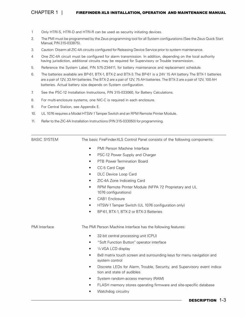
PMI Interface The PMI Person Machine Interface has the following features:
� 32-bit central processing unit (CPU)
� �Soft Function Button� operator interface
� 1/4 VGA LCD display
� 8x8 matrix touch screen and surrounding keys for menu navigation andsystem control
� Discrete LEDs for Alarm, Trouble, Security, and Supervisory event indica-tion and state of audibles
� System random-access memory (RAM)
� FLASH memory stores operating firmware and site-specific database
� Watchdog circuitry
1-4 DESCRIPTION
FIREFINDER-XLS INSTALLATION, OPERATION AND MAINTENANCE MANUAL | CHAPTER 1
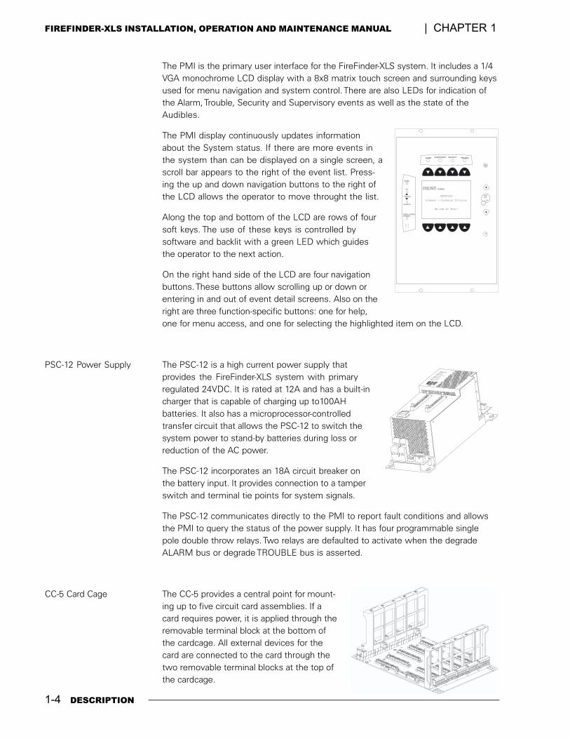
The PMI is the primary user interface for the FireFinder-XLS system. It includes a 1/4VGA monochrome LCD display with a 8x8 matrix touch screen and surrounding keysused for menu navigation and system control. There are also LEDs for indication ofthe Alarm, Trouble, Security and Supervisory events as well as the state of theAudibles.
The PMI display continuously updates informationabout the System status. If there are more events inthe system than can be displayed on a single screen, ascroll bar appears to the right of the event list. Press-ing the up and down navigation buttons to the right ofthe LCD allows the operator to move throught the list.
Along the top and bottom of the LCD are rows of foursoft keys. The use of these keys is controlled bysoftware and backlit with a green LED which guidesthe operator to the next action.
On the right hand side of the LCD are four navigationbuttons. These buttons allow scrolling up or down orentering in and out of event detail screens. Also on theright are three function-specific buttons: one for help,one for menu access, and one for selecting the highlighted item on the LCD.
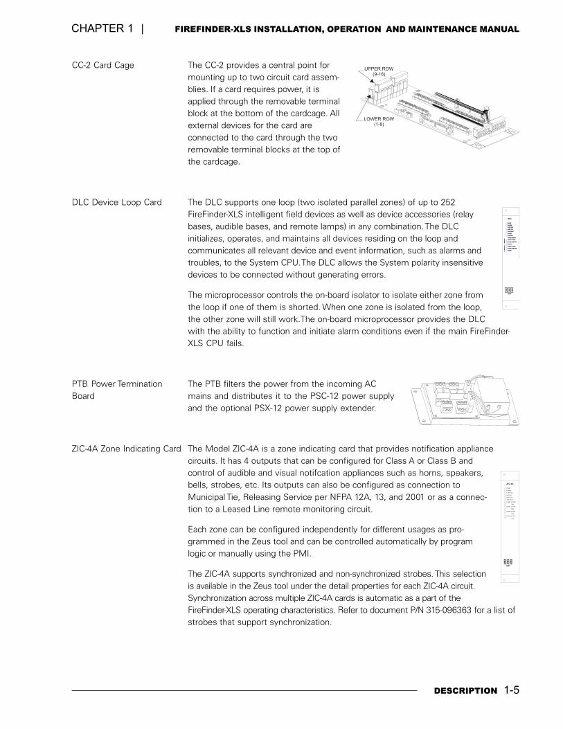
PSC-12 Power Supply The PSC-12 is a high current power supply thatprovides the FireFinder-XLS system with primaryregulated 24VDC. It is rated at 12A and has a built-incharger that is capable of charging up to100AHbatteries. It also has a microprocessor-controlledtransfer circuit that allows the PSC-12 to switch thesystem power to stand-by batteries during loss orreduction of the AC power.
The PSC-12 incorporates an 18A circuit breaker onthe battery input. It provides connection to a tamperswitch and terminal tie points for system signals.
The PSC-12 communicates directly to the PMI to report fault conditions and allowsthe PMI to query the status of the power supply. It has four programmable singlepole double throw relays. Two relays are defaulted to activate when the degradeALARM bus or degrade TROUBLE bus is asserted.
CC-5 Card Cage The CC-5 provides a central point for mount-ing up to five circuit card assemblies. If acard requires power, it is applied through theremovable terminal block at the bottom ofthe cardcage. All external devices for thecard are connected to the card through thetwo removable terminal blocks at the top ofthe cardcage.
More
Info
SECURITYALARM SUPERVISORY TROUBLE
SILENCED
PARTIAL SYSTEMDISABLED
AUDIBLES
ON
POWER
?
+_
....
10:32:05 04/15/01SYSTEM STATUS: NORMAL
HERACLES
Siemens - Cerberus Division
We Can Do That!
DESCRIPTION 1-5
CHAPTER 1 | FIREFINDER-XLS INSTALLATION, OPERATION AND MAINTENANCE MANUAL
CC-2 Card Cage The CC-2 provides a central point formounting up to two circuit card assem-blies. If a card requires power, it isapplied through the removable terminalblock at the bottom of the cardcage. Allexternal devices for the card areconnected to the card through the tworemovable terminal blocks at the top ofthe cardcage.
DLC Device Loop Card The DLC supports one loop (two isolated parallel zones) of up to 252FireFinder-XLS intelligent field devices as well as device accessories (relaybases, audible bases, and remote lamps) in any combination. The DLCinitializes, operates, and maintains all devices residing on the loop andcommunicates all relevant device and event information, such as alarms andtroubles, to the System CPU. The DLC allows the System polarity insensitivedevices to be connected without generating errors.
The microprocessor controls the on-board isolator to isolate either zone fromthe loop if one of them is shorted. When one zone is isolated from the loop,the other zone will still work.The on-board microprocessor provides the DLCwith the ability to function and initiate alarm conditions even if the main FireFinder-XLS CPU fails.
PTB Power Termination The PTB filters the power from the incoming ACBoard mains and distributes it to the PSC-12 power supply
and the optional PSX-12 power supply extender.
ZIC-4A Zone Indicating Card The Model ZIC-4A is a zone indicating card that provides notification appliancecircuits. It has 4 outputs that can be configured for Class A or Class B andcontrol of audible and visual notifcation appliances such as horns, speakers,bells, strobes, etc. Its outputs can also be configured as connection toMunicipal Tie, Releasing Service per NFPA 12A, 13, and 2001 or as a connec-tion to a Leased Line remote monitoring circuit.
Each zone can be configured independently for different usages as pro-grammed in the Zeus tool and can be controlled automatically by programlogic or manually using the PMI.
The ZIC-4A supports synchronized and non-synchronized strobes. This selectionis available in the Zeus tool under the detail properties for each ZIC-4A circuit.Synchronization across multiple ZIC-4A cards is automatic as a part of theFireFinder-XLS operating characteristics. Refer to document P/N 315-096363 for a list ofstrobes that support synchronization.
HNETHNET
Z
2
ONE
1
ENOZ
ALARMALARM
CLASS A OPEN
CLASS A RETURNCLASS A RETURN
CLASS A RETURNCLASS A RETURN
CLASS A OPEN
TROUBLE
ZONES STATUSZONES STATUS
SHORT
SHORT
CARD FAILCARD FAIL
GND FAULTGND FAULT
HNET FAIL
RESET
POWER
DLC
321
UPPER ROW(9-16)
LOWER ROW(1-8)
HNET
GND FAULT
TRBL
ZONE 4 ACTIVE
TRBL
ZONE 2 ACTIVE
ZONE 1 ACTIVE
TRBL
TRBL
ZONE 3 ACTIVE
CARD FAIL
HNET FAIL
CAN FAIL
RESET
POWER
ZIC-4A
+
-
1
+
-
2
+
-
3
1-6 DESCRIPTION
FIREFINDER-XLS INSTALLATION, OPERATION AND MAINTENANCE MANUAL | CHAPTER 1
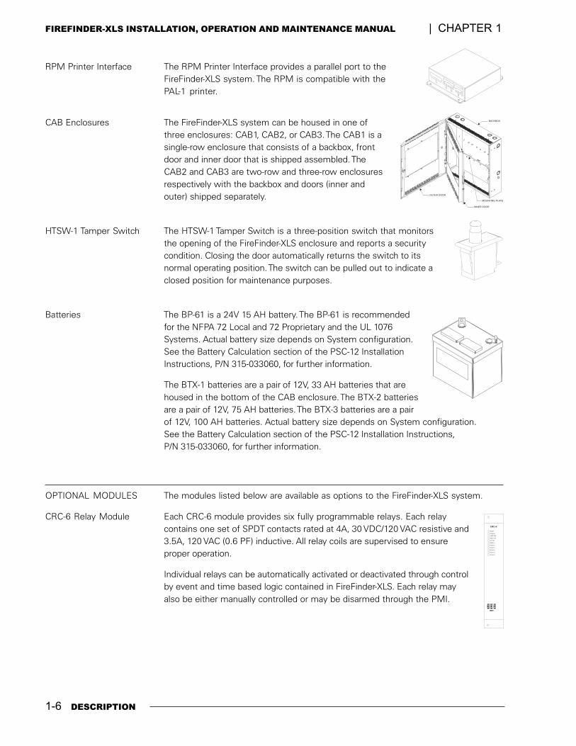
RPM Printer Interface The RPM Printer Interface provides a parallel port to theFireFinder-XLS system. The RPM is compatible with thePAL-1 printer.
CAB Enclosures The FireFinder-XLS system can be housed in one ofthree enclosures: CAB1, CAB2, or CAB3. The CAB1 is asingle-row enclosure that consists of a backbox, frontdoor and inner door that is shipped assembled. TheCAB2 and CAB3 are two-row and three-row enclosuresrespectively with the backbox and doors (inner andouter) shipped separately.
HTSW-1 Tamper Switch The HTSW-1 Tamper Switch is a three-position switch that monitorsthe opening of the FireFinder-XLS enclosure and reports a securitycondition. Closing the door automatically returns the switch to itsnormal operating position. The switch can be pulled out to indicate aclosed position for maintenance purposes.
Batteries The BP-61 is a 24V 15 AH battery. The BP-61 is recommendedfor the NFPA 72 Local and 72 Proprietary and the UL 1076Systems. Actual battery size depends on System configuration.See the Battery Calculation section of the PSC-12 InstallationInstructions, P/N 315-033060, for further information.
The BTX-1 batteries are a pair of 12V, 33 AH batteries that arehoused in the bottom of the CAB enclosure. The BTX-2 batteriesare a pair of 12V, 75 AH batteries. The BTX-3 batteries are a pairof 12V, 100 AH batteries. Actual battery size depends on System configuration.See the Battery Calculation section of the PSC-12 Installation Instructions,P/N 315-033060, for further information.
OPTIONAL MODULES The modules listed below are available as options to the FireFinder-XLS system.
CRC-6 Relay Module Each CRC-6 module provides six fully programmable relays. Each relaycontains one set of SPDT contacts rated at 4A, 30 VDC/120 VAC resistive and3.5A, 120 VAC (0.6 PF) inductive. All relay coils are supervised to ensureproper operation.
Individual relays can be automatically activated or deactivated through controlby event and time based logic contained in FireFinder-XLS. Each relay mayalso be either manually controlled or may be disarmed through the PMI.
HNET
RELAY 1
RELAY 5
RELAY 4
RELAY 2
RELAY 3
RELAY 6
CARD FAIL
24V FAIL
HNET FAIL
RESET
POWER
CRC-6
+
-
1
+
-
2
+
-
3
BACKBOX
OUTER DOOR
INNER DOOR
MOUNTING PLATE
DESCRIPTION 1-7
CHAPTER 1 | FIREFINDER-XLS INSTALLATION, OPERATION AND MAINTENANCE MANUAL
HNET
XNET FAIL
XNET
STYLE 7
ENABLED
CAN
ACTIVE NETWORKS
HNET/XNET STYLE
GROUND FAULT
NETWORKPORT
LOOP B FAIL
GND FAULT
LOOP A FAIL
STYLE 4
DISABLED
HNET
CARD FAIL
HNET FAIL
CAN FAIL
RESET
POWER
NIC-C
+
-
1
+
-
2
+
-
3
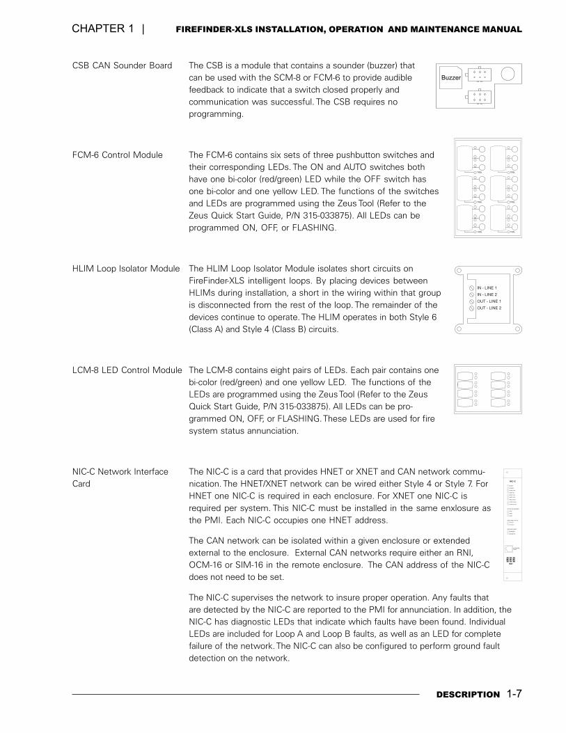
CSB CAN Sounder Board The CSB is a module that contains a sounder (buzzer) thatcan be used with the SCM-8 or FCM-6 to provide audiblefeedback to indicate that a switch closed properly andcommunication was successful. The CSB requires noprogramming.
FCM-6 Control Module The FCM-6 contains six sets of three pushbutton switches andtheir corresponding LEDs. The ON and AUTO switches bothhave one bi-color (red/green) LED while the OFF switch hasone bi-color and one yellow LED. The functions of the switchesand LEDs are programmed using the Zeus Tool (Refer to theZeus Quick Start Guide, P/N 315-033875). All LEDs can beprogrammed ON, OFF, or FLASHING.
HLIM Loop Isolator Module The HLIM Loop Isolator Module isolates short circuits onFireFinder-XLS intelligent loops. By placing devices betweenHLIMs during installation, a short in the wiring within that groupis disconnected from the rest of the loop. The remainder of thedevices continue to operate. The HLIM operates in both Style 6(Class A) and Style 4 (Class B) circuits.
LCM-8 LED Control Module The LCM-8 contains eight pairs of LEDs. Each pair contains onebi-color (red/green) and one yellow LED. The functions of theLEDs are programmed using the Zeus Tool (Refer to the ZeusQuick Start Guide, P/N 315-033875). All LEDs can be pro-grammed ON, OFF, or FLASHING. These LEDs are used for firesystem status annunciation.
NIC-C Network Interface The NIC-C is a card that provides HNET or XNET and CAN network commu-Card nication. The HNET/XNET network can be wired either Style 4 or Style 7. For
HNET one NIC-C is required in each enclosure. For XNET one NIC-C isrequired per system. This NIC-C must be installed in the same enxlosure asthe PMI. Each NIC-C occupies one HNET address.
The CAN network can be isolated within a given enclosure or extendedexternal to the enclosure. External CAN networks require either an RNI,OCM-16 or SIM-16 in the remote enclosure. The CAN address of the NIC-Cdoes not need to be set.
The NIC-C supervises the network to insure proper operation. Any faults thatare detected by the NIC-C are reported to the PMI for annunciation. In addition, theNIC-C has diagnostic LEDs that indicate which faults have been found. IndividualLEDs are included for Loop A and Loop B faults, as well as an LED for completefailure of the network. The NIC-C can also be configured to perform ground faultdetection on the network.
TRBL
TRBL
TRBL
TRBL
TRBL TRBL
Buzzer
IN - LINE 1
IN - LINE 2
OUT - LINE 1
OUT - LINE 2
1-8 DESCRIPTION
FIREFINDER-XLS INSTALLATION, OPERATION AND MAINTENANCE MANUAL | CHAPTER 1
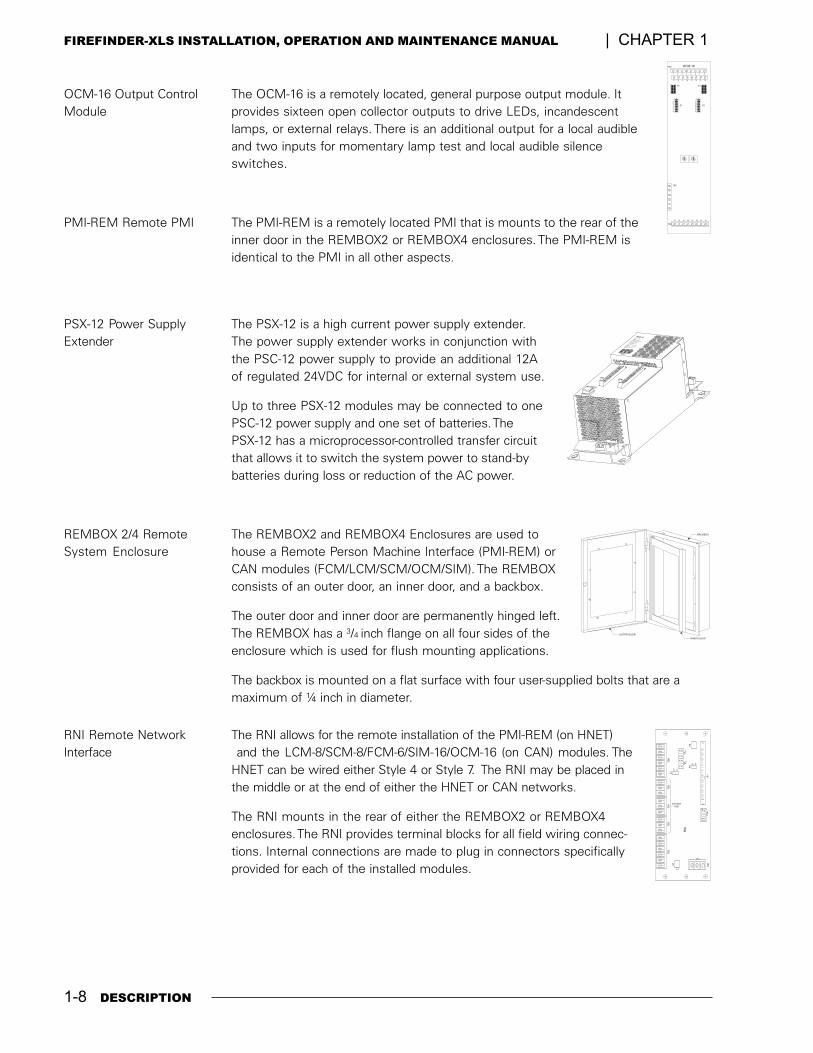
OCM-16 Output Control The OCM-16 is a remotely located, general purpose output module. ItModule provides sixteen open collector outputs to drive LEDs, incandescent
lamps, or external relays. There is an additional output for a local audibleand two inputs for momentary lamp test and local audible silenceswitches.
PMI-REM Remote PMI The PMI-REM is a remotely located PMI that is mounts to the rear of theinner door in the REMBOX2 or REMBOX4 enclosures. The PMI-REM isidentical to the PMI in all other aspects.
PSX-12 Power Supply The PSX-12 is a high current power supply extender.Extender The power supply extender works in conjunction with
the PSC-12 power supply to provide an additional 12Aof regulated 24VDC for internal or external system use.
Up to three PSX-12 modules may be connected to onePSC-12 power supply and one set of batteries. ThePSX-12 has a microprocessor-controlled transfer circuitthat allows it to switch the system power to stand-bybatteries during loss or reduction of the AC power.
REMBOX 2/4 Remote The REMBOX2 and REMBOX4 Enclosures are used toSystem Enclosure house a Remote Person Machine Interface (PMI-REM) or
CAN modules (FCM/LCM/SCM/OCM/SIM). The REMBOXconsists of an outer door, an inner door, and a backbox.
The outer door and inner door are permanently hinged left.The REMBOX has a 3/4 inch flange on all four sides of theenclosure which is used for flush mounting applications.
The backbox is mounted on a flat surface with four user-supplied bolts that are amaximum of ¼ inch in diameter.
RNI Remote Network The RNI allows for the remote installation of the PMI-REM (on HNET)Interface and the LCM-8/SCM-8/FCM-6/SIM-16/OCM-16 (on CAN) modules. The
HNET can be wired either Style 4 or Style 7. The RNI may be placed inthe middle or at the end of either the HNET or CAN networks.
The RNI mounts in the rear of either the REMBOX2 or REMBOX4enclosures. The RNI provides terminal blocks for all field wiring connec-tions. Internal connections are made to plug in connectors specificallyprovided for each of the installed modules.
1 2 3 4 5 6 7 8
9 10 11 12 13 14 15 16
17 18 19 20 21 22 23 24
1
23
4 5 6
78
901
23
4 5 6
78
90
S1
1
5
3
7
2
6
4
8
S2
TB2
TB1
P2 P3
TB3
1
5
3
7
2
6
4
8
OCM-16
X H
24 V
TB
1
12
910
P1
1 4
3 641
3 6
P3
P4
TB
2
RN
ITB
3T
B4
TB
5T
B6
2 1
JP
1
P6
S1
P5
P7
OF
F
ON
DO NOTUSE
OUTER DOOR
BACKBOX
INNER DOOR

DESCRIPTION 1-9
CHAPTER 1 | FIREFINDER-XLS INSTALLATION, OPERATION AND MAINTENANCE MANUAL
SCM-8 Switch Control The SCM-8 contains eight switches and eight pairs of LEDs.Each pair contains one bi-color (red/green) and one yellowLED. The functions of the switches and LEDs are pro-grammed using the Zeus Tool (Refer to the Zeus Quick StartGuide, P/N 315-033875). All LEDs can be programmed ON,OFF, or FLASHING. The SCM is used for manual control of thefire systems.
SIM-16 Supervised Input The SIM-16 is a remotely located, general purpose input module. Itprovides sixteen input circuits for remote system monitoring. Eachinput can be individually programmed as supervised (dry contacts only)or unsupervised (general-purpose input). The SIM-16 has two Form Crelays. The relays and the inputs are programmable using the Zeusprogramming tool.
SSD System Status Display The SSD displays the event status of a system remotely from the PMI.It has four 40 character alphanumeric LCD character lines,backlit upon status change or display toggling. This moduleis supervised by the main panel and also has LEDs and anoptional sounder to indicate the status of the system. TheSSD has the capability to store up to 1500 event messagesand has pushbuttons to scroll through these events. Itsdisplay is independent from the display on the PMI andduring the SSD initial power up, it is configured as a DisplayOnly module.
VOICE SYSTEM MODULES
AIC Audio Input Card The AIC (Audio Input Card) is a card that provides two externalisolated analog audio inputs to the voice system. External audiosources can be any of the following: tape recorder, CD player, radio,PBX interface (for convenience paging through the telephone sys-tem), etc.
The AIC contains two dry contact inputs to activate the two audioinputs separately.
Each input can be configured independently for different usages viathe Zeus programming tool. Each input can be controlled automati-cally via system logic dependant on its individual configuration ormanually by using the voice control panel. The input levels can beadjusted via the Zeus tool or manually with push buttons at the AICfront panel. During the initial power-up condition, each input is shut off.
1 2 3 4 5 6 7 8
12345678
9 10 11 12 13 14 15 16
910111213141516
1
23
4 5 6
78
901
23
4 5 6
78
90
TB2
TB1
P2
S1 S2
P3
TB3
1
1
6
6
TB4
SIM-16
AUDIBLES
SILENCED
ON
SUPERVISORYALARM
LOCALACK
TROUBLESECURITY
ZONE 1 ACTZONE 1 ACT
ZONE 2 ACTZONE 2 ACT
NORMAL
NORMAL
OVERLOAD
OVERLOAD
ZONE 1 TRBLZONE 1 TRBL
ZONE 2 TRBLZONE 2 TRBL
LOW
LOW
ZONE 1ZONE 1
ZONE 2ZONE 2
CARD FAILCARD FAIL
ASI FAILASI FAIL
CAN FAILCAN FAIL
RESET
POWER
AIC
CAN
+
-
1
+
-
2
1-10 DESCRIPTION
FIREFINDER-XLS INSTALLATION, OPERATION AND MAINTENANCE MANUAL | CHAPTER 1
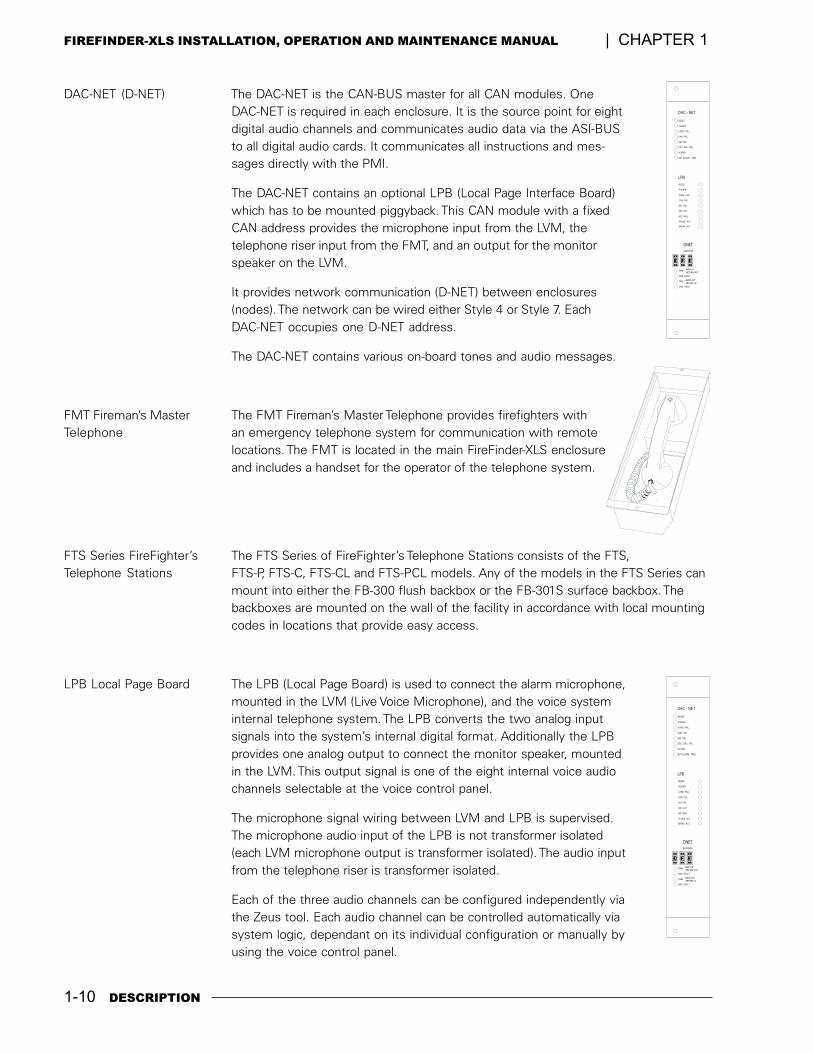
DAC-NET (D-NET) The DAC-NET is the CAN-BUS master for all CAN modules. OneDAC-NET is required in each enclosure. It is the source point for eightdigital audio channels and communicates audio data via the ASI-BUSto all digital audio cards. It communicates all instructions and mes-sages directly with the PMI.
The DAC-NET contains an optional LPB (Local Page Interface Board)which has to be mounted piggyback. This CAN module with a fixedCAN address provides the microphone input from the LVM, thetelephone riser input from the FMT, and an output for the monitorspeaker on the LVM.
It provides network communication (D-NET) between enclosures(nodes). The network can be wired either Style 4 or Style 7. EachDAC-NET occupies one D-NET address.
The DAC-NET contains various on-board tones and audio messages.
FMT Fireman�s Master The FMT Fireman�s Master Telephone provides firefighters withTelephone an emergency telephone system for communication with remote
locations. The FMT is located in the main FireFinder-XLS enclosureand includes a handset for the operator of the telephone system.
FTS Series FireFighter�s The FTS Series of FireFighter�s Telephone Stations consists of the FTS,Telephone Stations FTS-P, FTS-C, FTS-CL and FTS-PCL models. Any of the models in the FTS Series can
mount into either the FB-300 flush backbox or the FB-301S surface backbox. Thebackboxes are mounted on the wall of the facility in accordance with local mountingcodes in locations that provide easy access.
LPB Local Page Board The LPB (Local Page Board) is used to connect the alarm microphone,mounted in the LVM (Live Voice Microphone), and the voice systeminternal telephone system. The LPB converts the two analog inputsignals into the system�s internal digital format. Additionally the LPBprovides one analog output to connect the monitor speaker, mountedin the LVM. This output signal is one of the eight internal voice audiochannels selectable at the voice control panel.
The microphone signal wiring between LVM and LPB is supervised.The microphone audio input of the LPB is not transformer isolated(each LVM microphone output is transformer isolated). The audio inputfrom the telephone riser is transformer isolated.
Each of the three audio channels can be configured independently viathe Zeus tool. Each audio channel can be controlled automatically viasystem logic, dependant on its individual configuration or manually byusing the voice control panel.
TRBL—MAIN IN
RETURN OUT
—MAIN OUT
RETURN IN
GND FAULT
TRBL
GND FAULT
ADDRESS
DAC - NET
DNET
RESET
POWER
CARD FAIL
CAN FAIL
ASI FAIL
CPC -DAC FAIL
ALARM
EXT ALARM TRBL
LPB
RESET
POWER
CARD FAIL
CAN FAIL
ASI FAIL
MIC ACT
MIC TRBL
PHONE ACT
SPEAK ACT
+
-
1
+
-
2
+
-
3
TRBL—MAIN IN
RETURN OUT
—MAIN OUT
RETURN IN
GND FAULT
TRBL
GND FAULT
ADDRESS
DAC - NET
DNET
RESET
POWER
CARD FAIL
CAN FAIL
ASI FAIL
CPC -DAC FAIL
ALARM
EXT ALARM TRBL
LPB
RESET
POWER
CARD FAIL
CAN FAIL
ASI FAIL
MIC ACT
MIC TRBL
PHONE ACT
SPEAK ACT
+
-
1
+
-
2
+
-
3
DESCRIPTION 1-11
CHAPTER 1 | FIREFINDER-XLS INSTALLATION, OPERATION AND MAINTENANCE MANUAL
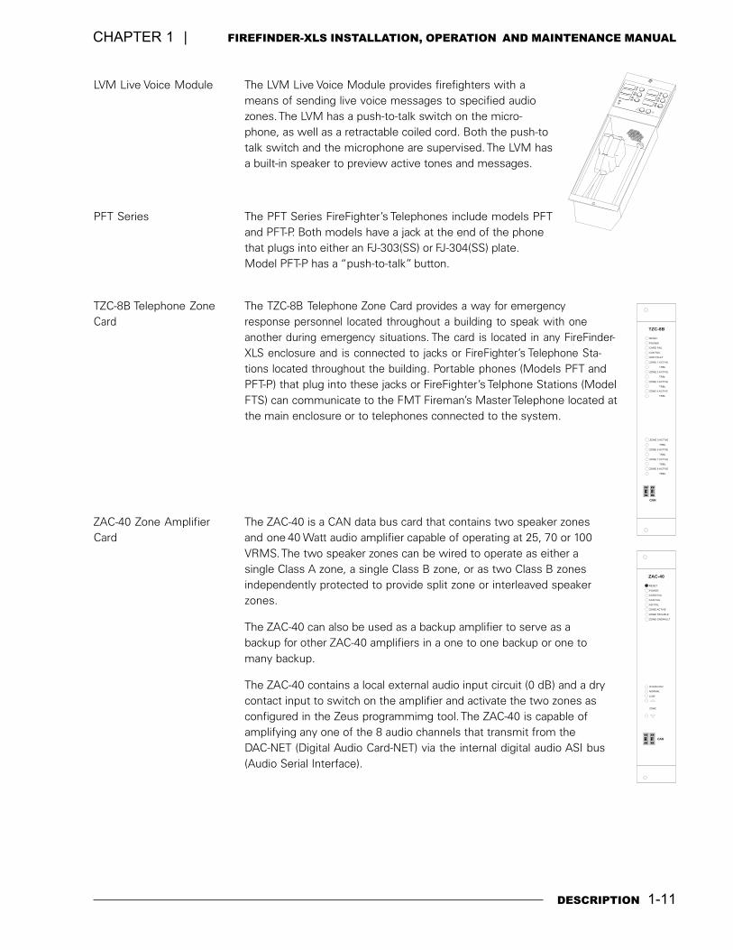
LVM Live Voice Module The LVM Live Voice Module provides firefighters with ameans of sending live voice messages to specified audiozones. The LVM has a push-to-talk switch on the micro-phone, as well as a retractable coiled cord. Both the push-totalk switch and the microphone are supervised. The LVM hasa built-in speaker to preview active tones and messages.
PFT Series The PFT Series FireFighter�s Telephones include models PFTand PFT-P. Both models have a jack at the end of the phonethat plugs into either an FJ-303(SS) or FJ-304(SS) plate.Model PFT-P has a �push-to-talk� button.
TZC-8B Telephone Zone The TZC-8B Telephone Zone Card provides a way for emergencyCard response personnel located throughout a building to speak with one
another during emergency situations. The card is located in any FireFinder-XLS enclosure and is connected to jacks or FireFighter�s Telephone Sta-tions located throughout the building. Portable phones (Models PFT andPFT-P) that plug into these jacks or FireFighter�s Telphone Stations (ModelFTS) can communicate to the FMT Fireman�s Master Telephone located atthe main enclosure or to telephones connected to the system.
ZAC-40 Zone Amplifier The ZAC-40 is a CAN data bus card that contains two speaker zonesCard and one 40 Watt audio amplifier capable of operating at 25, 70 or 100
VRMS. The two speaker zones can be wired to operate as either asingle Class A zone, a single Class B zone, or as two Class B zonesindependently protected to provide split zone or interleaved speakerzones.
The ZAC-40 can also be used as a backup amplifier to serve as abackup for other ZAC-40 amplifiers in a one to one backup or one tomany backup.
The ZAC-40 contains a local external audio input circuit (0 dB) and a drycontact input to switch on the amplifier and activate the two zones asconfigured in the Zeus programmimg tool. The ZAC-40 is capable ofamplifying any one of the 8 audio channels that transmit from theDAC-NET (Digital Audio Card-NET) via the internal digital audio ASI bus(Audio Serial Interface).
CAN
ZONE ACTIVE
ZONE TROUBLE
ZONE GNDFAULT
OVERLOAD
NORMAL
LOW
ZONE
CARD FAIL
ASI FAIL
CAN FAIL
RESET
POWER
ZAC-40
+
-
1
+
-
2
CAN
TRBL
TRBL
TRBL
TRBL
ZONE 2 ACTIVE
ZONE 6 ACTIVE
ZONE 1 ACTIVE
ZONE 5 ACTIVE
ZONE 4 ACTIVE
ZONE 8 ACTIVE
TRBL
TRBL
TRBL
TRBL
ZONE 3 ACTIVE
ZONE 7 ACTIVE
CARD FAIL
GND FAULT
CAN FAIL
RESET
POWER
TZC-8B
+
-
1
+
-
2
1-12 DESCRIPTION
FIREFINDER-XLS INSTALLATION, OPERATION AND MAINTENANCE MANUAL | CHAPTER 1
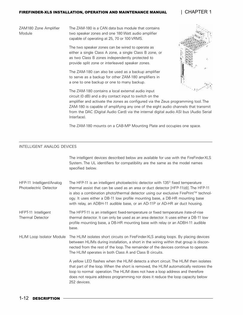
ZAM180 Zone Amplifier The ZAM-180 is a CAN data bus module that containsModule two speaker zones and one 180 Watt audio amplifier
capable of operating at 25, 70 or 100 VRMS.
The two speaker zones can be wired to operate aseither a single Class A zone, a single Class B zone, oras two Class B zones independently protected toprovide split zone or interleaved speaker zones.
The ZAM-180 can also be used as a backup amplifierto serve as a backup for other ZAM-180 amplifiers ina one to one backup or one to many backup.
The ZAM-180 contains a local external audio inputcircuit (0 dB) and a dry contact input to switch on theamplifier and activate the zones as configured via the Zeus programming tool. TheZAM-180 is capable of amplifying any one of the eight audio channels that transmitfrom the DAC (Digital Audio Card) via the internal digital audio ASI bus (Audio SerialInterface).
The ZAM-180 mounts on a CAB-MP Mounting Plate and occupies one space.
INTELLIGENT ANALOG DEVICES
The intelligent devices described below are available for use with the FireFinder-XLSSystem. The UL identifiers for compatibility are the same as the model namesspecified below.
HFP-11 Intelligent/Analog The HFP-11 is an intelligent photoelectric detector with 135O fixed temperaturethermal assist that can be used as an area or duct detector [HFP-11(d)]. The HFP-11is also a combination photo/thermal detector using our exclusive FirePrintTM technol-ogy. It uses either a DB-11 low profile mounting base, a DB-HR mounting basewith relay, an ADBH-11 audible base, or an AD-11P or AD-HR air duct housing.
HFPT-11 Intelligent The HFPT-11 is an intelligent fixed-temperature or fixed temperature /rate-of-risethermal detector. It can only be used as an area detector. It uses either a DB-11 lowprofile mounting base, a DB-HR mounting base with relay or an ADBH-11 audiblebase.
HLIM Loop Isolator Module The HLIM isolates short circuits on FireFinder-XLS analog loops. By placing devicesbetween HLIMs during installation, a short in the wiring within that group is discon-nected from the rest of the loop. The remainder of the devices continue to operate.The HLIM operates in both Class A and Class B circuits.
A yellow LED flashes when the HLIM detects a short circuit. The HLIM then isolatesthat part of the loop. When the short is removed, the HLIM automatically restores theloop to normal operation. The HLIM does not have a loop address and thereforedoes not require address programming nor does it reduce the loop capacity below252 devices.
Photoelectric Detector
Thermal Detector
DESCRIPTION 1-13
CHAPTER 1 | FIREFINDER-XLS INSTALLATION, OPERATION AND MAINTENANCE MANUAL
HMS-2S and HMS-SA The HMS-2S/-SA is an intelligent manual station designed to interface with a DLCloop. The HMS-2S/-SA manual station housing has a pull down lever that locks inposition after releasing a spring loaded switch. To indicate the manual station isactivated, the pull down lever remains down and locked until the station is physicallyreset. The HMS-SA manual station has a set of normally closed auxiliary contactswhich are available for releasing door holders and magnetic door locks.
The HMS-2S has a keyswitch which can activate a second address.
HMS-S/-D Intelligent The HMS-S/-D is an intelligent manual station designed to interface with a DLC loop.The HMS-S is a single-action station; the HMS-D is a double-action station. The HMScan be flush mounted or surface mounted using the SB-5R mounting box.
HMS-M Intelligent Manual The HMS-M is an intelligent metal manual station designed to interface with a DLCloop. The HMS-M is a single action station; when used with the Model HMS-FDAdapter, the HMS-M is double action.
HTRI-M Intelligent Interface The HTRI-M intelligent interface module interfaces direct shorting contact deviceswith the DLC loops.The HTRI-M can monitor a normally open or closed dry contactand it can report the status of the contact.
HTRI-S, HTRI-R and HTRI-D The HTRI-S/-R/-D series modules are intelligent interface modules that interfacedirect shorting contact devices with the DLC loops.The HTRI-S is a single-inputmodule; the HTRI-R is a single-input module with an independently controllableForm C relay; the HTRI-D is a dual-input module.
HZM Remote Conventional The HZM is a FireFinder-XLS intelligent device that connects a single zone ofconventional devices to a DLC device loop card. The HZM can power up to fifteencompatible 2-wire, ionization or photoelectric smoke detectors or it can power onePB-1191 Beam Detector. It can also monitor an unlimited number of shorting devicessuch as waterflow switches, thermal detectors, manual stations, etc.
The HZM supports Class A and Class B wiring. The module uses one address on thedevice loop. It does not require any mechanical address programming. Use the DPUDevice Programming Unit to program and test the module.
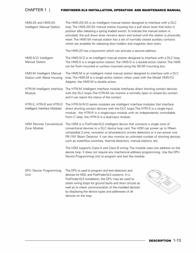
DPU Device Programming The DPU is used to program and test detectors anddevices for MXL and FireFinder-XLS systems. In aFireFinder-XLS installation, the DPU may be used tocheck wiring loops for ground faults and short circuits aswell as to check communication of the installed devicesby displaying the device types and addresses of alldevices on the loop.
Intelligent Manual Station
Manual Station
Station with Metal Housing
Module
Intelligent Interface Modules
Zone Module
Unit
8
90
C
2
3
4
5
6
7
1

1-14 DESCRIPTION
FIREFINDER-XLS INSTALLATION, OPERATION AND MAINTENANCE MANUAL | CHAPTER 1
2
INSTALLATION 2-1
INTRODUCTION This section provides general instructions for mounting and wiring the FireFinder-XLSControl Panel.
Read this section before installing the equipment to ensure proper installation. If youare not familiar with the FireFinder-XLS System, also read the first section of themanual. Be sure to ask Siemens Building Technologies, Inc. Technical Support or anauthorized Representative if you have any questions.
Install and use the FireFinder-XLS System in accordance with the appropriate Local,NFPA and NEC Code requirements.
INSTALLATION GUIDELINES
AlwAlwAlwAlwAlwaaaaayyyyys remos remos remos remos remove powerve powerve powerve powerve power (battery and AC) and wait at least 10 seconds to allow thesupply voltages to decay before installing or removing any module, cable or wiring.
Follow Steps 1 through 21 for installation. Each step is thoroughly explained in thereferenced installation instructions. A description of all compatible FireFinder-XLSsystem modules and devices can be found in the FireFinder-XLS Installation Instruc-tions Index, P/N 315-034242.
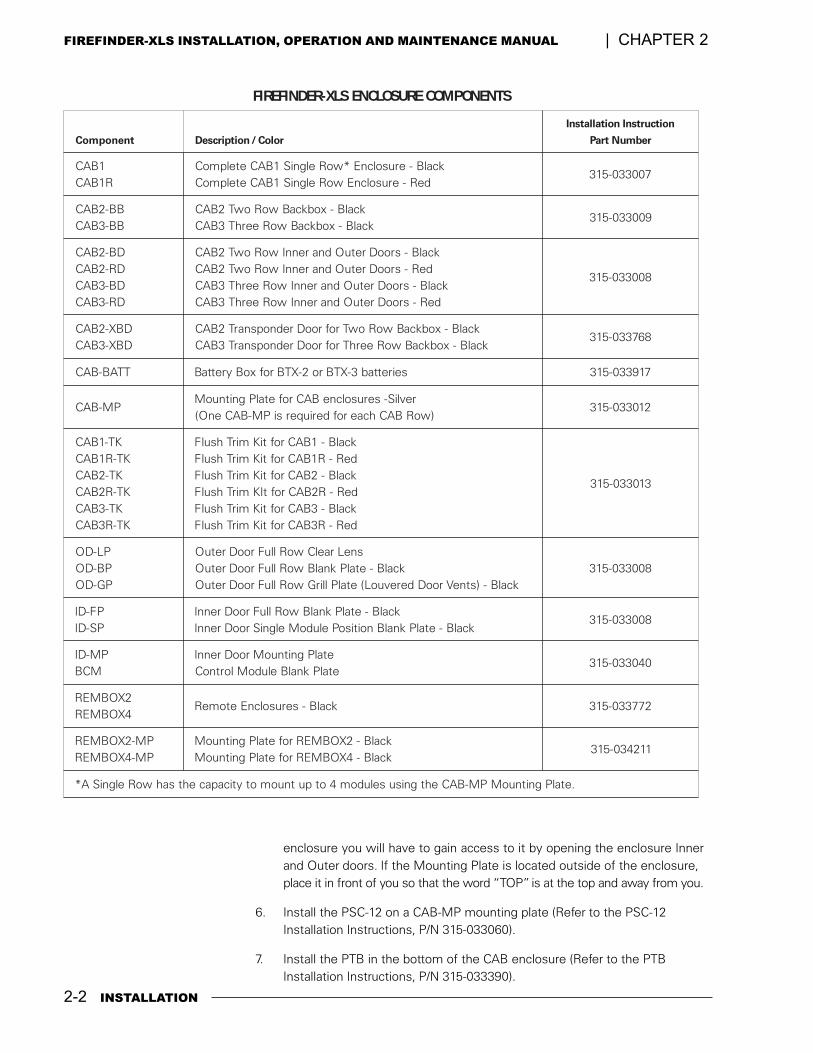
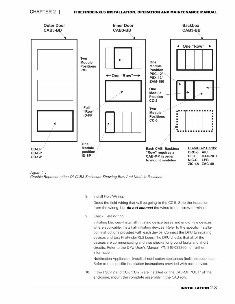
1. Install the desired enclosure; CAB1, CAB2 or CAB3. Refer to the CABEnclosure Components table on page 2-2 to select the appropriate installationinstructions. Refer also to Figure 2-1 on page 2-3 for information on CABrows and module placement.
2. Install the HTSW-1 Tamper Switch where required (Refer to the HTSW-1Installation Instructions, P/N 315-033350).
3. Pull the field wiring into the backbox and dress it to approximately where itwill go.
4. Install the PMI on the inner door (Refer to the PMI Installation Instructions,P/N 315-033070).
5. Install the CC-5/CC-2 on a CAB-MP mounting plate (Refer to the CC-5/CC-2Installation Instructions, P/N 315-033035). Do not install the card guides inthe CC-5/CC-2 at this time.
The Mounting Plate may be located either �IN� or �OUT� of the enclosure toperform this installation procedure. If the Mounting Plate is located �IN� the
2-2 INSTALLATION
FIREFINDER-XLS INSTALLATION, OPERATION AND MAINTENANCE MANUAL | CHAPTER 2
enclosure you will have to gain access to it by opening the enclosure Innerand Outer doors. If the Mounting Plate is located outside of the enclosure,place it in front of you so that the word �TOP� is at the top and away from you.
6. Install the PSC-12 on a CAB-MP mounting plate (Refer to the PSC-12Installation Instructions, P/N 315-033060).
7. Install the PTB in the bottom of the CAB enclosure (Refer to the PTBInstallation Instructions, P/N 315-033390).
SLX-REDNIFERIF STNENOPMOCERUSOLCNE
tnenopmoC roloC/noitpircseD
noitcurtsnInoitallatsnI
rebmuNtraP
1BACR1BAC
kcalB-erusolcnE*woRelgniS1BACetelpmoCdeR-erusolcnEwoRelgniS1BACetelpmoC
700330-513
BB-2BACBB-3BAC
kcalB-xobkcaBwoRowT2BACkcalB-xobkcaBwoReerhT3BAC
900330-513
DB-2BACDR-2BACDB-3BACDR-3BAC
kcalB-srooDretuOdnarennIwoRowT2BACdeR-srooDretuOdnarennIwoRowT2BAC
kcalB-srooDretuOdnarennIwoReerhT3BACdeR-srooDretuOdnarennIwoReerhT3BAC
800330-513
DBX-2BACDBX-3BAC
kcalB-xobkcaBwoRowTrofrooDrednopsnarT2BACkcalB-xobkcaBwoReerhTrofrooDrednopsnarT3BAC
867330-513
TTAB-BAC seirettab3-XTBro2-XTBrofxoByrettaB 719330-513
PM-BACrevliS-serusolcneBACrofetalPgnitnuoM
)woRBAChcaerofderiuqersiPM-BACenO(210330-513
KT-1BACKT-R1BAC
KT-2BACKT-R2BAC
KT-3BACKT-R3BAC
kcalB-1BACroftiKmirThsulFdeR-R1BACroftiKmirThsulFkcalB-2BACroftiKmirThsulFdeR-R2BACroftIKmirThsulFkcalB-3BACroftiKmirThsulFdeR-R3BACroftiKmirThsulF
310330-513
PL-DOPB-DOPG-DO
sneLraelCwoRlluFrooDretuOkcalB-etalPknalBwoRlluFrooDretuO
kcalB-)stneVrooDderevuoL(etalPllirGwoRlluFrooDretuO800330-513
PF-DIPS-DI
kcalB-etalPknalBwoRlluFrooDrennIkcalB-etalPknalBnoitisoPeludoMelgniSrooDrennI
800330-513
PM-DIMCB
etalPgnitnuoMrooDrennIetalPknalBeludoMlortnoC
040330-513
2XOBMER4XOBMER
kcalB-serusolcnEetomeR 277330-513
PM-2XOBMERPM-4XOBMER
kcalB-2XOBMERrofetalPgnitnuoMkcalB-4XOBMERrofetalPgnitnuoM
112430-513
.etalPgnitnuoMPM-BACehtgnisuseludom4otputnuomotyticapacehtsahwoRelgniSA*
INSTALLATION 2-3
CHAPTER 2 | FIREFINDER-XLS INSTALLATION, OPERATION AND MAINTENANCE MANUAL
Outer Door
CAB3-BD
Backbox
CAB3-BB
One “Row”
OneModulePositionPSC-12/PSX-12/ZAM-180
One “Row”
Inner Door
CAB3-BD
Each CAB Backbox“Row” requires aCAB-MP in orderto mount modules
OD-LPOD-BPOD-GP
OneModulepositionID-SP
Full“Row”ID-FP
TwoModulePositionsCC-5
TwoModulePositionsPMI
CC-5/CC-2 Cards:
CRC-6
ZIC-4A
DLCNIC-C
OneModulePositionCC-2
AICDAC-NETLPBZAC-40
Figure 2-1Graphic Representation Of CAB3 Enclosure Showing Row And Module Positions
8. Install Field Wiring.
Dress the field wiring that will be going to the CC-5. Strip the insulationfrom the wiring, but do not connect the wires to the screw terminals.
9. Check Field Wiring.
Initiating Devices�Install all initiating device bases and end-of-line deviceswhere applicable. Install all initiating devices. Refer to the specific installa-tion instructions provided with each device. Connect the DPU to initiatingdevices and test FireFinder-XLS loops. The DPU checks that all of thedevices are communicating and also checks for ground faults and shortcircuits. Refer to the DPU User�s Manual, P/N 315-033260, for furtherinformation.
Notification Appliances�Install all notification appliances (bells, strobes, etc.)Refer to the specific installation instructions provided with each device.
10. If the PSC-12 and CC-5/CC-2 were installed on the CAB-MP �OUT� of theenclosure, mount the complete assembly in the CAB row.
2-4 INSTALLATION
FIREFINDER-XLS INSTALLATION, OPERATION AND MAINTENANCE MANUAL | CHAPTER 2
11. Connect Field Wiring to CC-5/CC-2 screw terminals, as appropriate.
12. Install card guides in CC-5/CC-2.
13. Install the required modules. Refer to the Installation Instruction Index,P/N 315-034242 for a list of all compatilbe FireFinder-XLS system modules.
Do not place any modules behind the LVM and the FMT, specifically the PSC-12,PSX-12, CC-5, CC-2 and ZAM-180.
14. On the PSC-12, set the circuit breaker for the battery to the OFF position.
Verify that the AC dedicated circuit breaker is turned off at the mains.
15. Connect the AC mains and battery wiring to the PTB.
16. Connect the PTB output to the PSC-12.
17. Turn on the dedicated circuit breaker.
18. Turn on the PSC-12 circuit breaker for the battery.
19. The System will initialize in default mode.
20. Using the Zeus programming tool, transfer the site-specific program to theFireFinder-XLS system. Refer to the Zeus Quick Start Manual, P/N 315-033875, for further information. Upon completion, the system will automati-cally initialize. FireFinder-XLS will interrogate the system and verify that thesystem agrees with the Zeus configuration.
21. Any problem found will be reported in the PMI. Identify all discrepanciesand correct them until the system reports SYSTEM STATUS: NORMAL.
3
OPERATION 3-1
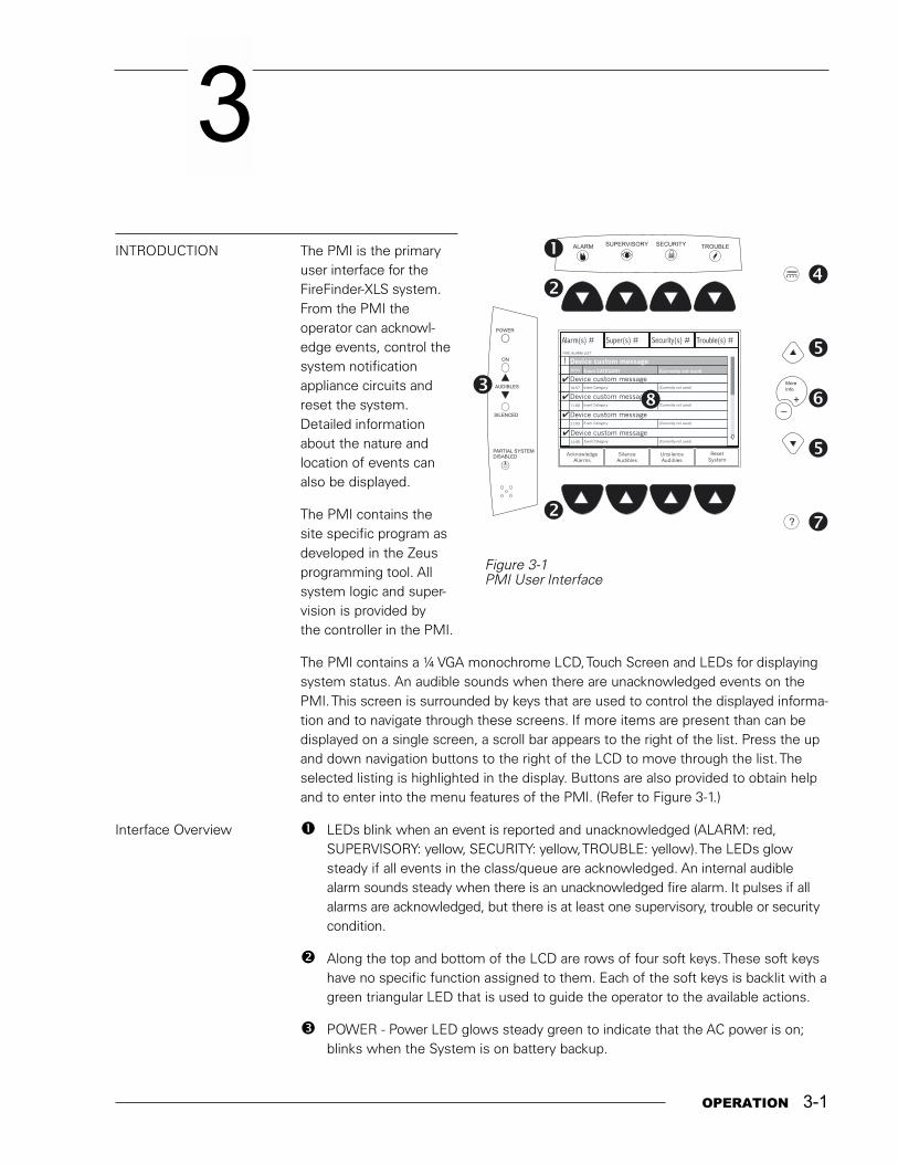
INTRODUCTION The PMI is the primaryuser interface for theFireFinder-XLS system.From the PMI theoperator can acknowl-edge events, control thesystem notificationappliance circuits andreset the system.Detailed informationabout the nature andlocation of events canalso be displayed.
The PMI contains thesite specific program asdeveloped in the Zeusprogramming tool. Allsystem logic and super-vision is provided bythe controller in the PMI.
The PMI contains a ¼ VGA monochrome LCD, Touch Screen and LEDs for displayingsystem status. An audible sounds when there are unacknowledged events on thePMI. This screen is surrounded by keys that are used to control the displayed informa-tion and to navigate through these screens. If more items are present than can bedisplayed on a single screen, a scroll bar appears to the right of the list. Press the upand down navigation buttons to the right of the LCD to move through the list. Theselected listing is highlighted in the display. Buttons are also provided to obtain helpand to enter into the menu features of the PMI. (Refer to Figure 3-1.)
Interface Overview ! LEDs blink when an event is reported and unacknowledged (ALARM: red,SUPERVISORY: yellow, SECURITY: yellow, TROUBLE: yellow). The LEDs glowsteady if all events in the class/queue are acknowledged. An internal audiblealarm sounds steady when there is an unacknowledged fire alarm. It pulses if allalarms are acknowledged, but there is at least one supervisory, trouble or securitycondition.
" Along the top and bottom of the LCD are rows of four soft keys. These soft keyshave no specific function assigned to them. Each of the soft keys is backlit with agreen triangular LED that is used to guide the operator to the available actions.
# POWER - Power LED glows steady green to indicate that the AC power is on;blinks when the System is on battery backup.
Figure 3-1PMI User Interface
SECURITYALARM SUPERVISORY TROUBLE
SILENCED
PARTIAL SYSTEMDISABLED
AUDIBLES
ON
POWER
?
More
Info
+_
Alarm(s) #
FIRE ALARM LIST
Super(s) # Security(s) # Trouble(s) #
Device custom message10:53
!
Device custom messageEvent Category
Event Category
11:00 (Currently not used)
Device custom message10:57 (Currently not used)
�
�
�
�
Device custom messageEvent Category11:03 (Currently not used)
Device custom messageEvent Category
AcknowledgeAlarms
SilenceAudibles
UnsilenceAudibles
ResetSystem
11:06 (Currently not used)
�
�
�
�
�
�
�
�
�
�
(Currently not used)
....
3-2 OPERATION
FIREFINDER-XLS INSTALLATION, OPERATION AND MAINTENANCE MANUAL | CHAPTER 3
AUDIBLES - Audibles ON or Audibles SILENCED glows steady yellow.
PARTIAL SYSTEM DISABLED - Partial System Disabled glows steady yellowwhen any module/device is disabled.
$ Press .... to display a MENU of available information.
% Scroll UP / Scroll DOWN - Use the scroll up button to navigate up or the scrolldown button to navigate down a list to choose a specific entry from the list ofinformation displayed on the screen. If the button remains depressed, the listscrolls progressively faster until it reaches ten items at a time.
& MORE INFO (+ / �) - Use More Info/+/- to navigate or drill down (+) or up (�)through the levels of detail about a selected entry. When viewing a report that islonger than one screen, pressing (�) highlights the last entry of the report andpressing (+) highlights the first entry of the report.
' HELP - Press ? for context-sensitive help. Press ? again or press the Exit Helpsoft key to return to your previous position. If no key presses are made for 60seconds, the help will time out and return to the previous screen.
( Touch screen display - Touch selections on the screen when there are optionsthat are not selectable using the soft keys. Use of the touch screen is notrequired in Alert mode.
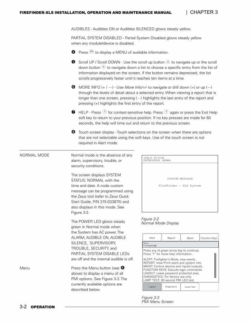
NORMAL MODE Normal mode is the absence of anyalarm, supervisory, trouble, orsecurity conditions.
The screen displays SYSTEMSTATUS: NORMAL with thetime and date. A node custommessage can be programmed usingthe Zeus tool (refer to Zeus QuickStart Guide, P/N 315-033875) andalso displays in this mode. SeeFigure 3-2.
The POWER LED glows steadygreen in Normal mode whenthe System has AC power. TheALARM, AUDIBLE ON, AUDIBLESILENCE, SUPERVISORY,TROUBLE, SECURITY, andPARTIAL SYSTEM DISABLE LEDsare off and the internal audible is off.
Menu Press the Menu button (see $above) to display a menu of allPMI options. See Figure 3-3. Thecurrently available options aredescribed below.
CUSTOM MESSAGE
FireFinder - XLS System
10:26:12 07/12/02
SYSTEM STATUS: NORMAL
Figure 3-2Normal Mode Display
Figure 3-3PMI Menu Screen
Alert Report Maint
10:53 Category text information
Logout Diagnostics Lamp Test
Press any lit green arrow key to continue.
Press “?” for more help information.
ALERT: Firefighter’s Mode, view events.
REPORT: View/Print event and system info.
MAINT: Control devices and inputs/outputs.
FUNCTION KEYS: Execute logic commands.
LOGOUT: Leave password protected area.
DIAGNOSTICS: For factory use only.
LAMP TEST: 30 second PMI LED test.
Function Keys
MenuFireFighter@1
OPERATION 3-3
CHAPTER 3 | FIREFINDER-XLS INSTALLATION, OPERATION AND MAINTENANCE MANUAL
ALERT MODE When an Alarm, Security, Supervisory or Trouble event occurs in the system, thedisplay enters the Alert or Firefighter�s mode automatically. The events are displayedin priority order (Alarm, Supervisory, Security, Trouble), the local audible sounds andthe appropriate LED blinks. If the event caused notification appliances to sound, theAudibles On indicator lights. At the bottom of the screen an Acknowledge soft key isdisplayed if the highest unacknowledged queue is selected. Pressing this keyacknowledges the event and silences the local audible.
Once all events are acknowledged and audibles are silenced, a Reset System softkey becomes available in the lower right side of the display. If notification applianceswere active, two additional soft keys become available at the bottom of the screen.These allow the operator to silence or unsilence the notification appliances (audibles).When the notification appliances are silenced the Audibles Silenced LED lights.
Press the More Info/+ button to display a screen showing details relating to theselected event. Additional soft keys appear at the bottom of this screen, includingone that displays a map of the area in which the event occurred, provided this informa-tion has been programmed using the Zeus tool. The operator can return to theprevious screen by pressing the (�) button, which is adjacent to the More Info/+button.
Event counts in PMIs and SSDs may differ because SSDs currently display only�primitive� (individual) events, while a group PMI whose devices are programmedinto groups in Zeus will display only one queue event per group.
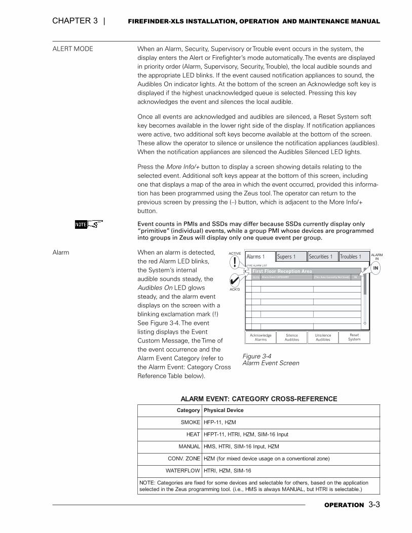
Alarm When an alarm is detected,the red Alarm LED blinks,the System�s internalaudible sounds steady, theAudibles On LED glowssteady, and the alarm eventdisplays on the screen with ablinking exclamation mark (!)See Figure 3-4. The eventlisting displays the EventCustom Message, the Time ofthe event occurrence and theAlarm Event Category (refer tothe Alarm Event: Category CrossReference Table below).
Alarms 1
FIRE ALARM LIST
Supers 1 Securities 1 Troubles 1
First Floor Reception AreaAlarm Event CATEGORY10:53 IN(This Area Currently Not Used)
Acknowledge
AlarmsSilence
Audibles
Unsilence
Audibles
Reset
System
ACTIVE
ACK’D
ALARMIN
IN
Figure 3-4Alarm Event Screen
ECNEREFER-SSORCYROGETAC:TNEVEMRALA
yrogetaC eciveDlacisyhP
EKOMS MZH,11-PFH
TAEH tupnI61-MIS,MZH,IRTH,11-TPFH
LAUNAM MZH,tupnI61-MIS,IRTH,SMH
ENOZ.VNOC )enozlanoitnevnocanoegasueciveddeximrof(MZH
WOLFRETAW 61-MIS,MZH,IRTH
noitacilppaehtnodesab,srehtorofelbatcelesdnasecivedemosrofdexiferaseirogetaC:ETON).elbatcelessiIRTHtub,LAUNAMsyawlasiSMH,.e.i(.lootgnimmargorpsueZehtnidetceles
3-4 OPERATION
FIREFINDER-XLS INSTALLATION, OPERATION AND MAINTENANCE MANUAL | CHAPTER 3
In addition, the System responds to alarms with other output functions (as pro-grammed in the Zeus tool) such as other audible signals.
An Acknowledge Alarms soft key displays in the bottom left corner of the screen.Press this key to acknowledge each alarm and to silence the local audible. Theblinking exclamation point (!) then changes to a check mark ()). See Figure 3-4. (If thesystem is programmed as NFPA 72D in the Zeus tool, it is necessary to individuallyacknowledge each alarm.)
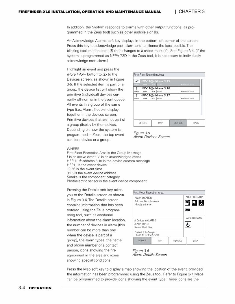
Highlight an event and press theMore Info/+ button to go to theDevices screen, as shown in Figure3-5. If the selected item is part of agroup, the device list will show theprimitive (individual) devices cur-rently off-normal in the event queue.All events in a group of the sametype (i.e., Alarm, Trouble) displaytogether in the devices screen.Primitive devices that are not part ofa group display by themselves.Depending on how the system isprogrammed in Zeus, the top eventcan be a device or a group.
WHERE:First Floor Reception Area is the Group Message! is an active event; ) is an acknowledged eventHFP-11 @ address 3:15 is the device custom messageHFP11 is the event device10:56 is the event time3:15 is the event device addressSmoke is the component categoryPhotoelectric sensor is the event device component
Pressing the Details soft key takesyou to the Details screen as shownin Figure 3-6. The Details screencontains information that has beenentered using the Zeus program-ming tool, such as additionalinformation about the alarm location,the number of devices in alarm (thisnumber can be more than onewhen the device is part of agroup), the alarm types, the nameand phone number of a contactperson, icons showing the fireequipment in the area and iconsshowing special conditions.
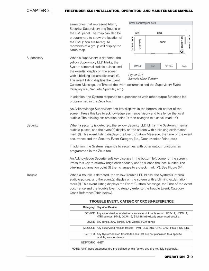
Press the Map soft key to display a map showing the location of the event, providedthe information has been programmed using the Zeus tool. Refer to Figure 3-7. Mapscan be programmed to provide icons showing the event type. These icons are the
Figure 3-5Alarm Devices Screen
Contact: John SamplePhone #: 973.555.1234
AREA FIRE EQUIP:
AREA CONTAINS:
DETAILS MAP DEVICES BACK
ALARM LOCATION:
1st Floor Reception Area
- Lobby entrance
# Devices in ALARM: 3
ALARM TYPES:
Smoke, Heat, Flow
First Floor Reception Area
Figure 3-6Alarm Details Screen
DETAILS MAP DEVICES BACK
HFP-11@address 3:15:3-15HFP11 10:56
First Floor Reception Area
Smoke Photoelectric sensor
HFP-11@address 3:16:3-16HFP11 10:57 Smoke Photoelectric sensor
HFP-11@address 3:17:3-17HFP11 10:58 Smoke Photoelectric sensor
!
!
OPERATION 3-5
CHAPTER 3 | FIREFINDER-XLS INSTALLATION, OPERATION AND MAINTENANCE MANUAL
same ones that represent Alarm,Security, Supervisory and Trouble onthe PMI panel. The map can also beprogrammed to show the location ofthe PMI (�You are here�). Allmembers of a group will display thesame map.
Supervisory When a supervisory is detected, theyellow Supervisory LED blinks, theSystem�s internal audible pulses, andthe event(s) display on the screenwith a blinking exclamation mark (!).This event listing displays the EventCustom Message, the Time of the event occurrence and the Supervisory EventCategory (i.e., Security, Sprinkler, etc.).
In addition, the System responds to supervisories with other output functions (asprogrammed in the Zeus tool).
An Acknowledge Supervisory soft key displays in the bottom left corner of thescreen. Press this key to acknowledge each supervisory and to silence the localaudible. The blinking exclamation point (!) then changes to a check mark ()).
Security When a security is detected, the yellow Security LED blinks, the System�s internalaudible pulses, and the event(s) display on the screen with a blinking exclamationmark (!). This event listing displays the Event Custom Message, the Time of the eventoccurrence and the Security Event Category (i.e., Door, Monitor Point, etc.).
In addition, the System responds to securities with other output functions (asprogrammed in the Zeus tool).
An Acknowledge Security soft key displays in the bottom left corner of the screen.Press this key to acknowledge each security and to silence the local audible. Theblinking exclamation point (!) then changes to a check mark ()). See Figure 3-4.
Trouble When a trouble is detected, the yellow Trouble LED blinks, the System�s internalaudible pulses, and the event(s) display on the screen with a blinking exclamationmark (!). This event listing displays the Event Custom Message, the Time of the eventoccurrence and the Trouble Event Category (refer to the Trouble Event: CategoryCross Reference Table below).
DETAILS
SHOP
LAV HALL
RE
CE
PT
ION
MA
INS
TR
EE
T
SH
IPP
ING
LO
AD
ING
DO
CK
MAP DEVICES BACK
First Floor Reception Area
Figure 3-7Sample Map Screen
ECNEREFER-SSORCYROGETAC:TNEVEELBUORT
yrogetaC eciveDlacisyhP
ECIVED ,11-TPFH,11-PFH:troperelbuorttiucric/enozroecivedtupnidesivrepusynA.stiucricdesivrepusyllaudividni61-MIS,61-MCO,SMH,secivedIRTH
ENOZ senozMZH,senoZMAZ,senoZCAZ,senozCIZ
ELUDOM .CIN,XSP,CSP,MAZ,CRC,CIZ,CLD,IMP-elbuorteludomdesivrepusynA
METSYS cificepsaotdetniopniptoneratahtseruliaf/elbuortdetaler-metsySynA.ecivedroenoz,eludom
KROWTEN TENH
.elbatcelesdleiftoneradnayrotcafehtybdenifed-erperaseirogetacesehtfollA:ETON
3-6 OPERATION
FIREFINDER-XLS INSTALLATION, OPERATION AND MAINTENANCE MANUAL | CHAPTER 3
In addition, the System responds to troubles with other output functions (as pro-grammed in the Zeus tool).
An Acknowledge Trouble soft key displays in the bottom left corner of the screen.Press this key to acknowledge each trouble and to silence the local audible. Theblinking exclamation point (!) then changes to a check mark ()). See Figure 3-4.
If acknowledged troubles remain in the queue, the system will sound the localaudible every 24 hours as a reminder. A message will appear on the PMI and thesounder will remain on until it is silenced.
Reset Procedures There are two types of reset procedures that can be performed on the FireFinder-XLSSystem: Hard Reset and Soft Reset.
Hard Reset Other terms for Hard Reset are Power-up, Initialization, and Cold Reset. Applyingpower to the system performs a Hard Reset. Doing so initializes the entire system.
What Is Lost:� Alarm, supervisory, trouble, and security conditions (provided they have
returned to the normal state).
� Arm/disarm.
� Manual sensitivity adjustment.
What Is Not Lost:� Zeus program.
� Time and date.
� History log.
� Time-based control.
Soft Reset A Soft Reset is performed by pressing the Reset System soft key. The system canonly be reset when all events (alarms, supervisories, securities and troubles) areacknowledged and the notification appliances are silenced.
What Is Lost:� Alarm, supervisory, trouble, and security conditions (provided they have
returned to the normal state).
What Is Not Lost:� Any user entries such as time and date.
� Arm/disarm.
� Zeus program.
� Manual sensitivity adjustment.
� Time-based control.
REPORT MODE (Reporting Detector Sensitivities)
Press the Menu button on the PMI (upper right) and select the Report option bypressing the key with the lit green triangle pointing to the Report label.
Press the More Info/+ button on the PMI to navigate to the desired loop or specificdevice. When More Info is pressed once it displays the FireFinder-XLS node.
OPERATION 3-7
CHAPTER 3 | FIREFINDER-XLS INSTALLATION, OPERATION AND MAINTENANCE MANUAL
� Press the More Info/+ button again to display a list of FireFinder-XLSmodules; use the up and down buttons to select the desired module.
� Press the More Info/+ button again to display a list of FireFinder-XLS sub-modules (provided your system has sub-modules installed); use the up anddown buttons to select the desired sub-module.
� Press the More Info/+ button again to display a list of FireFinder-XLSdevices; use the up and down buttons to select the desired device.
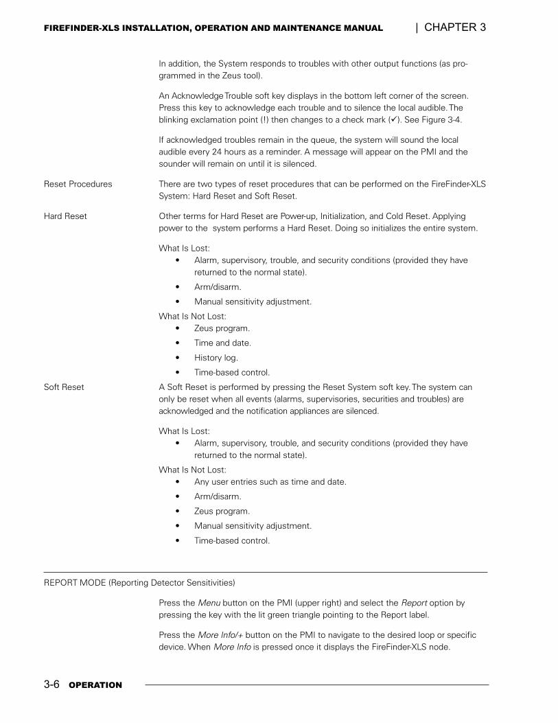
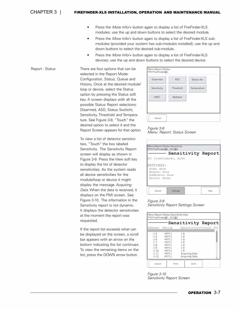
Report - Status There are four options that can beselected in the Report Mode:Configuration, Status, Queue andHistory. Once at the desired module/loop or device, select the Statusoption by pressing the Status softkey. A screen displays with all thepossible Status Report selections:Disarmed, ASD, Status Sw(itch),Sensitivity, Threshold and Tempera-ture. See Figure 3-8. �Touch� thedesired option to select it and theReport Screen appears for that option.
To view a list of detector sensitivi-ties, �Touch� the box labeledSensitivity. The Sensitivity Reportscreen will display as shown inFigure 3-9. Press the View soft keyto display the list of detectorsensitivities. As the system readsall device sensitivities for themodule/loop or device it mightdisplay the message AcquiringData. When the data is received, itdisplays on the PMI screen. SeeFigure 3-10. The information in theSensitivity report is not dynamic.It displays the detector sensitivitiesat the moment the report wasrequested.
If the report list exceeds what canbe displayed on the screen, a scrollbar appears with an arrow on thebottom indicating the list continues.To view the remaining items on thelist, press the DOWN arrow button.
10:53Category text information
:1-3 HFP11 1.9:1-4 HFP11 1.9:1-5 HFP11 1.9:1-6 HFP11 1.9:1-7 HFP11 1.9:1-8 HFP11 1.9:1-9 HFP11 1.9:1-10 HFP11 1.9:1-11 HFP11 Acquiring Data:1-12 HFP11 Acquiring Data
Menu:Report:Status:Sensitivity:ViewPHY:FireFinder@1, DLC@1
Cancel Print
Sensitivity ReportAddress Device Sensitivity(%/Foot) 25%
:1-3 HFP11 1.9
GoTo
Figure 3-10Sensitivity Report Screen
Figure 3-9Sensitivity Report Settings Screen
Figure 3-8Menu: Report: Status Screen
Menu:Report:Status
PHY:FireFinder@1
Cancel
Disarmed
Sensitivity Threshold Temperature
ASD Status Sw
HNET Walktest
Menu:Report:Status:SensitivityPHY:FireFinder@1, DLC@1
Sensitivity ReportAT: FireFinder@1, DLC@1
Cancel Settings View
SETTINGS:Node: None
Module: None
SubModule: None
Device: Smoke
3-8 OPERATION
FIREFINDER-XLS INSTALLATION, OPERATION AND MAINTENANCE MANUAL | CHAPTER 3
If the down arrow button remains depressed, the list scrolls progressively faster untilit reaches ten items at a time. When viewing a report that is longer than one screen,pressing (�) highlights the last entry of the report and pressing (+) highlights the firstentry of the report.
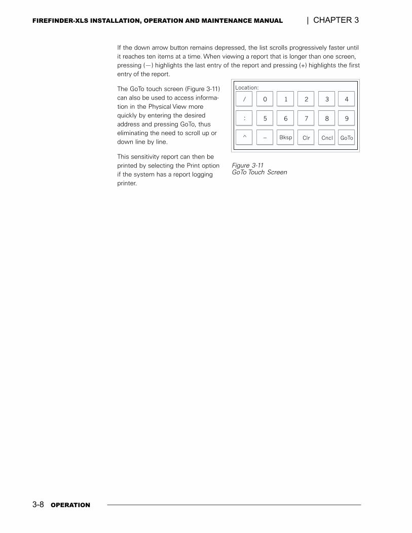
The GoTo touch screen (Figure 3-11)can also be used to access informa-tion in the Physical View morequickly by entering the desiredaddress and pressing GoTo, thuseliminating the need to scroll up ordown line by line.
This sensitivity report can then beprinted by selecting the Print optionif the system has a report loggingprinter.
Location:
/
:
^
0 1 2 3 4
5 6 7 8 9
_ Bksp Clr Cncl GoTo
Figure 3-11GoTo Touch Screen
4
VOICE SYSTEM 4-1
INTRODUCTION The eight-channel digital evacuation FireFinder-XLS Voice system can be added to thebasic FireFinder-XLS fire alarm system. This is accomplished with the addition of theDAC-NET Digital Audio card and its accompanying submodules (ZAC, LVM/LPB, SCM-8,ZIC, FMT, TZC-8B) and zone-installed equipment (speakers, strobes, telephones).
The system is capable of automatically or manually signaling to its installed speakerzone circuits (ZAC). The signal can be up to eight channels of prerecorded messagesand/or tones including up to two simultaneous channels of live paging. The tones andprerecorded messages are configurable in the Zeus programming tool and areavailable for upload to each installed DAC-NET. A maximum of 32 DAC-NET modulescan be installed in each FireFinder-XLS system. Each DAC-NET may input either itsown tone/message to a channel, or it may be programmed to use a tone/messagefrom another DAC-NET in the system.
Individual zone circuits (speaker, strobe, telephone) are bundled into geographicgroups during system configuration. These groups are either automatically controlledby pre-programmed system logic, or manually controlled by the switches located onone or more Command Stations. Paging, manual control, or monitoring of the speakeror telephone groups can be performed from any location where an LVM/LPB micro-phone, SCM switch control module, or PMI is installed.
EQUIPMENT The Control and Indicating equipment of a FinderFinder-XLS Voice system consists ofthe following components:
� LED Control Module (LCM)
� Switch Control Module (SCM)
� Live Voice Microphone (LVM)
� Firefighters Master Telephone (FMT)
� Telephone Zone Card (TZC-8B)
� Person Machine Interface (PMI)
COMMAND STATIONS Each FireFinder-XLS Command Station configuration is unique. The requirements ofthe project determine the modules needed to achieve the desired functionality. TheControl view of the Zeus Programming tool is used to configure the Commandstations. Each switch on the LVM, SCM and FCM may be configured for any of themanual operations (See page 4-4).
4-2 VOICE SYSTEM
FIREFINDER-XLS INSTALLATION, OPERATION AND MAINTENANCE MANUAL | CHAPTER 4
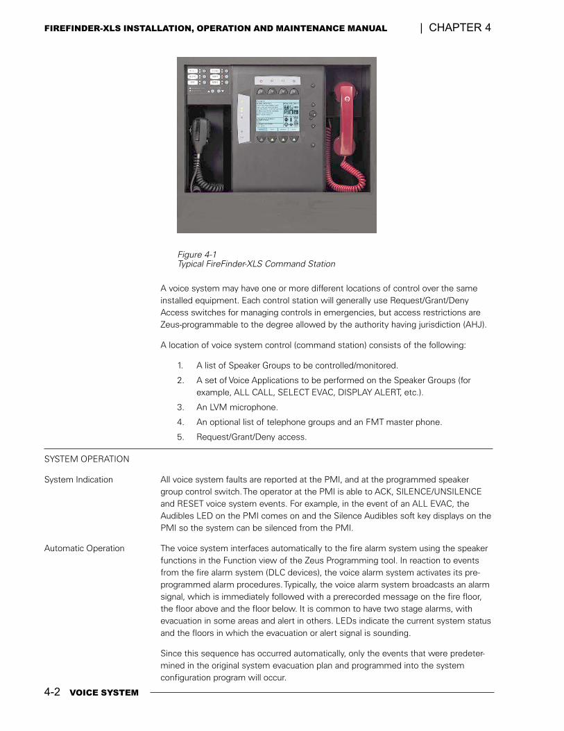
Figure 4-1Typical FireFinder-XLS Command Station
A voice system may have one or more different locations of control over the sameinstalled equipment. Each control station will generally use Request/Grant/DenyAccess switches for managing controls in emergencies, but access restrictions areZeus-programmable to the degree allowed by the authority having jurisdiction (AHJ).
A location of voice system control (command station) consists of the following:
1. A list of Speaker Groups to be controlled/monitored.
2. A set of Voice Applications to be performed on the Speaker Groups (forexample, ALL CALL, SELECT EVAC, DISPLAY ALERT, etc.).
3. An LVM microphone.
4. An optional list of telephone groups and an FMT master phone.
5. Request/Grant/Deny access.
SYSTEM OPERATION
System Indication All voice system faults are reported at the PMI, and at the programmed speakergroup control switch. The operator at the PMI is able to ACK, SILENCE/UNSILENCEand RESET voice system events. For example, in the event of an ALL EVAC, theAudibles LED on the PMI comes on and the Silence Audibles soft key displays on thePMI so the system can be silenced from the PMI.
Automatic Operation The voice system interfaces automatically to the fire alarm system using the speakerfunctions in the Function view of the Zeus Programming tool. In reaction to eventsfrom the fire alarm system (DLC devices), the voice alarm system activates its pre-programmed alarm procedures. Typically, the voice alarm system broadcasts an alarmsignal, which is immediately followed with a prerecorded message on the fire floor,the floor above and the floor below. It is common to have two stage alarms, withevacuation in some areas and alert in others. LEDs indicate the current system statusand the floors in which the evacuation or alert signal is sounding.
Since this sequence has occurred automatically, only the events that were predeter-mined in the original system evacuation plan and programmed into the systemconfiguration program will occur.
VOICE SYSTEM 4-3
CHAPTER 4 | FIREFINDER-XLS INSTALLATION, OPERATION AND MAINTENANCE MANUAL
Evacuation Signal (EVAC) A steady red LED indicates that an evacuation signal (tone or message) is being sentto the entire building or to selected areas of the building requesting that the occu-pants evacuate. It is possible to have two different evacuation signals, EVAC 1 andEVAC 2. EVAC 2 will be overridden by EVAC 1 to the same speaker group.
Alert Signal A flashing red LED indicates that an ALERT signal (tone or message) is being sent tothe entire building or selected areas to alert occupants. It is possible to have twodifferent alert signals, ALERT 1 and ALERT 2. ALERT 2 will be overridden by ALERT 1to the same speaker group.
Manual Operation Once the first few minutes have been dealt with automatically, the voice alarmsystem can be taken over manually by authorized personnel.
Manual voice operation functions such as emergency paging, evacuation or alertsignal activation, firefighters' telephone operation, multiple voice system commandcenter operation, as well as convenience page or background music operation arepossible at any time.
Emergency Page Emergency Page allows a live voice page from the emergency microphone to all orselected speaker groups in the building. An optional preannouncement tonepreceeds emergency pages for a duration of time set in the Zeus programming tool.
Evacuation Signal (EVAC) EVAC sends the evacuation tone or message (predetermined in system design) to allor selected speaker groups in the building. The EVAC signal will be overridden by anemergency page to the same speaker group.
It is possible to have two different evacuation signals, EVAC 1 and EVAC 2. EVAC 2will be overridden by EVAC 1 to the same speaker group.
Alert Signal Alert signal sends the alert tone or message (predetermined in system design) to allor selected speaker groups in the building. The alert signal will be overridden by anemergency page or an evacuation signal to the same speaker group.
It is possible to have two different alert signals, ALERT 1 and ALERT 2. ALERT 2 willbe overridden by ALERT 1 to the same speaker group.
Convenience Page Convenience Page allows a live voice page from the convenience page microphoneto all or selected speaker groups in the building. Convenience pages are a low priorityfunction and will be overridden by an emergency page, an evacuation or an alertsignal to the same speaker group.
Background Music Background Music sends background music from an external audio input to all orselected speaker groups in the building. Background Music is the lowest priority andwill be overridden by an emergency page, an evacuation or alert signal and a conve-nience page to the same speaker group.
SYSTEM PRIORITIES The priority of requests to a speaker group in the case that multiple signals (audiochannels) are requested at the same time are as follows:
1. Emergency Page (highest priority) 2. Warden�s (Phone) Page
3. Evacuation Signal 1 (EVAC 1) 4. Evacuation Signal 2 (EVAC 2)
5. Alert Signal 1 (ALERT 1) 6. Alert Signal 2 (ALERT 2)
7. Convenience Page 8. Background Music (lowest priority)
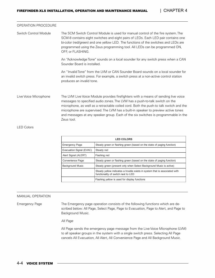
4-4 VOICE SYSTEM
FIREFINDER-XLS INSTALLATION, OPERATION AND MAINTENANCE MANUAL | CHAPTER 4
OPERATION PROCEDURE
Switch Control Module The SCM Switch Control Module is used for manual control of the fire system. TheSCM-8 contains eight switches and eight pairs of LEDs. Each LED pair contains onebi-color (red/green) and one yellow LED. The functions of the switches and LEDs areprogrammed using the Zeus programming tool. All LEDs can be programmed ON,OFF, or FLASHING.
An �Acknowledge Tone� sounds on a local sounder for any switch press when a CANSounder Board is installed.
An �Invalid Tone� from the LVM or CAN Sounder Board sounds on a local sounder foran invalid switch press. For example, a switch press at a non-active control stationproduces an invalid tone.
Live Voice Microphone The LVM Live Voice Module provides firefighters with a means of sending live voicemessages to specified audio zones. The LVM has a push-to-talk switch on themicrophone, as well as a retractable coiled cord. Both the push-to talk switch and themicrophone are supervised. The LVM has a built-in speaker to preview active tonesand messages at any speaker group. Each of the six switches is programmable in theZeus tool.
LED Colors
SROLOCDEL
egaPycnegremE )noitcnufgnigapfoetatsehtnodesab(neerggnihsalfroneergydaetS
)CAVE(langiSnoitaucavE derydaetS
)TRELA(langiStrelA dergnihsalF
egaPecneinevnoC )noitcnufgnigapfoetatsehtnodesab(neerggnihsalfroneergydaetS
cisuMdnuorgkcaB )evitcasicisuMdnuorgkcaBtceleSnehwylnotneserp(neergydaetS
htiwdetaicossasitahtmetsysnistsixeelbuortasetacidniwolleyydaetSDELottxenhctiwsfoytilanoitcnuf
snoitcnufyalpsidrofdesusiwolleygnihsalF
MANUAL OPERATION
Emergency Page The Emergency page operation consists of the following functions which are de-scribed below: All Page, Select Page, Page to Evacuation, Page to Alert, and Page toBackground Music.
All Page
All Page sends the emergency page message from the Live Voice Microphone (LVM)to all speaker groups in the system with a single switch press. Selecting All Pagecancels All Evacuation, All Alert, All Convenience Page and All Background Music.
VOICE SYSTEM 4-5
CHAPTER 4 | FIREFINDER-XLS INSTALLATION, OPERATION AND MAINTENANCE MANUAL
To select All Page, follow the steps listed below.
1. Pick up the Live Voice Microphone.
2. Depress the All Page switch.
3. The All Page switch and All Speaker Group switch LEDs flash green.
4. Depress the key on the Live Voice Microphone
5. The All Speaker Group switch LEDs turn steady green, indicating that allspeaker groups are now turned on.
6. Once the microphone is keyed, a preannouncement tone sounds on allspeaker groups for approximately 3 seconds (0-10 seconds is program-mable in Zeus).
7. While the preannouncement tone is sounding, the Pre-Announce ToneLED is on steady to give visual indication to the operator of what iscurrently sounding.
8. When the preannouncement tone ends, the Pre-Announce Tone LED turnsoff and the Ready to Page LED turns on telling the operator to proceedwith the page.
9. The operator can now speak and make the page to all speaker groups.
10. During the page, the operator can briefly (for up to 5 seconds) unkey andthen re-key the microphone (for example, to cough) - without re-initiatingthe pre-announce tone.
11. To end the page, the operator simply unkeys and replaces the microphone.The Ready to Page LED turns off.
12. All Speaker Group switch LEDs turn from steady green to flashing green.
13. To return the system to normal, the operator depresses the All Pageswitch; otherwise, the system will automatically return to normal inapproximately 1-2 minutes and turn off the All Page and Speaker GroupLEDs.
This sequence of operation assumes the system is normal and no alarms exist. If therewere alarms in the system, the All Page would operate the exact same way - except thatthe speaker groups that were receiving an evacuation or alert signal would be overriddenby the Page. Once the Page ends, the previously sounding evacuation or alert signals wouldresume on the floors/groups that were sounding before the page.
Select Page
Select Page sends the emergency page message from the Live Voice Microphone(LVM) to selected speaker groups in the system. Choosing Select Page cancelsSelect Evacuation, Select Alert, Select Convenience Page and Select BackgroundMusic.
To select Select Page, follow the steps listed below.
1. Pick up the Live Voice Microphone.
2. Depress the Select Page switch and then the switch for the desiredindividual speaker group.
3. The Select Page switch and the selected Speaker Group switch LEDs flashgreen.
4-6 VOICE SYSTEM
FIREFINDER-XLS INSTALLATION, OPERATION AND MAINTENANCE MANUAL | CHAPTER 4
4. If no Speaker Group switches are pressed for 120 seconds, the systemautomatically returns to normal.
5. Depress the key on the Live Voice Microphone.
6. The LED on the selected Speaker Group switch turns steady green indicat-ing that the speaker group is now turned on.
7. Once the microphone is keyed, a preannouncement tone sounds on thespeaker group for approximately 3 seconds (0-10 seconds is programmablein Zeus).
8. While the preannouncement tone is sounding, the Pre-Announce Tone LEDis on steady to give the operator a visual indication of what is sounding.
9. When the preannouncement tone ends, the Pre-Announce Tone LED turnsoff and the Ready to Page LED turns on telling the operator to proceed withthe page.
10. The operator can now speak and make the page to the selected speakergroups.
11. During the page, the operator can briefly (for up to 5 seconds) unkey andthen re-key the microphone (for example, to cough) - without re-initiating thepre-announce tone.
12. To end the page the operator simply unkeys and replaces the microphone.The Ready to Page LED turns off.
13. The Select Page and the selected Speaker Group switch LEDs turn fromsteady green to flashing green.
14. To return the system to normal the operator depresses Select Page and theselected Speaker Group switches; otherwise, the system will return tonormal automatically in approximately 1-2 minutes and turn off the SelectPage and selected Speaker Group LEDs.
This sequence of operation assumes the system is normal and no alarms exist. If there werealarms in the system, the Select Page would operate the exact same way - except that thespeaker groups that were receiving an evacuation or alert signal would be overridden by thepage. Once the page ends, the previously sounding evacuation or alert signals would resumeon the floors/groups that were sounding before the page.
Page to Evacuation
Page to Evacuation sends the emergency page message with a single switch pressfrom the Live Voice Microphone (LVM) to all speaker groups in the system that arereceiving an evacuation signal.
To select Page to Evacuation, follow the steps listed below.
1. The LEDs of the selected speaker groups receiving an evacuation signal aresteady red.
2. Pick up the Live Voice Microphone.
3. Depress the Page to Evacuation switch.
4. The Page to Evacuation switch LED and the LEDs of the selected SpeakerGroups receiving an EVAC signal flash green.
5. Depress the key on the Live Voice Microphone.
VOICE SYSTEM 4-7
CHAPTER 4 | FIREFINDER-XLS INSTALLATION, OPERATION AND MAINTENANCE MANUAL
6. The selected Speaker Group switch LEDs turn steady green indicating thatthe speaker groups are now turned on.
7. Once the microphone is keyed, a preannouncement tone sounds on thespeaker groups for approximately 3 seconds (0-10 seconds is programmablein Zeus).
8. While the preannouncement tone is sounding, the Pre-Announce Tone LEDis on steady to give the operator a visual indication of what is sounding.
9. When the preannouncement tone ends, the Pre-Announce Tone LED turnsoff and the Ready to Page LED turns on telling the operator to proceed withthe page.
10. The operator can now speak and make the page.
11. During the page the operator can briefly (for up to 5 seconds) unkey andthen re-key the microphone (for example, to cough) without re-initiating thepre-announce tone.
12. To end the page, the operator can simply unkey and replace the microphone,the Ready to Page LED turns off.
13. The Page to Evacuation and the Speaker Group switch LEDs turn fromsteady green to flashing green.
14. To cancel Page to Evacuation, the operator depresses the Page to Evacua-tion switch; otherwise, the system will return to its previous state automati-cally in approximately 1-2 minutes and turn off the Page to Evacuation LED.
15. The selected speaker groups resume receiving an evacuation signal.
Page to Alert
Page to Alert sends the emergency page message, with a single switch press, fromthe Live Voice Microphone (LVM) to all speaker groups in the system currentlyreceiving an alert signal.
To select Page to Alert, follow the steps listed below.
1. The LEDs of the selected speaker groups receiving an alert signal areflashing red.
2. Pick up the Live Voice Microphone.
3. Depress the Page to Alert switch.
4. The Page to Alert switch and selected Speaker Group switch LEDs flashgreen.
5. Depress the key on the Live Voice Microphone.
6. The selected Speaker Group switch LEDs turn steady green indicating thatthe speaker groups are now turned on.
7. Once the microphone is keyed, a preannouncement tone sounds on thespeaker groups for approximately 3 seconds (0-10 seconds is programmablein Zeus)).
8. While the preannouncement tone is sounding the Pre-Announce Tone LEDis on steady to give the operator a visual indication of what is sounding.
9. When the preannouncement tone ends, the Pre-Announce Tone LED turnsoff and the Ready to Page LED turns on telling the operator to proceed withthe page.

4-8 VOICE SYSTEM
FIREFINDER-XLS INSTALLATION, OPERATION AND MAINTENANCE MANUAL | CHAPTER 4
10. The operator can now speak and make the page.
11. During the page, the operator can briefly (for up to 5 seconds) unkey andthen re-key the microphone (for example, to cough) without re-initiating thepre-announce tone.
12. To end the page, the operator simply unkeys and replaces the microphone,the Ready to Page LED turns off.
13. The Page to Alert and the Speaker Group switch LEDs turn from steadygreen to flashing green.
14. To return the system to normal, the operator depresses the Page to Alertswitch; otherwise, the system will return to normal automatically in approxi-mately 1-2 minutes and turn off the Page to Alert LED.
15. The selected speaker groups resume receiving an Alert signal.
Page to Background Music
Page to Background Music sends the emergency page message with a single switchpress from the Live Voice Microphone (LVM) to all speaker groups in the systemcurrently receiving background music.
To select Page to Background Music, follow the steps listed below.
1. The LEDs of the selected speaker groups receiving background music arenormally off.
2. Pick up the Live Voice Microphone.
3. Depress the Page to Background Music switch.
4. The Page to Background Music switch and selected Speaker Group switchLEDs flash green.
5. Depress the key on the Live Voice Microphone.
6. The selected Speaker Group switch LEDs turn steady green indicating thatthe speaker groups are now turned on.
7. Once the microphone is keyed, a preannouncement tone sounds on thespeaker groups for approximately 3 seconds (0-10 seconds is programmablein Zeus).
8. While the preannouncement tone is sounding, the Pre-Announce Tone LEDis on steady to give the operator a visual indication of what is sounding.
9. When the preannouncement tone ends, the Pre-Announce Tone LED turnsoff and the Ready to Page LED turns on telling the operator to proceed withthe page.
10. The operator can now speak and make the page.
11. During the page, the operator can briefly (for up to 5 seconds) unkey andthen re-key the microphone (for example, to cough) without re-initiating thepre-announce tone.
12. To end the page, the operator simply unkeys and replaces the microphone.The Ready to Page LED turns off.
13. The Page to Background Music and the Speaker Group switch LEDs turnfrom steady green to flashing green.
VOICE SYSTEM 4-9
CHAPTER 4 | FIREFINDER-XLS INSTALLATION, OPERATION AND MAINTENANCE MANUAL
14. To return the system to normal, the operator depresses the Page to Back-ground Music switch; otherwise, the system will return to normal automati-cally in approximately 1-2 minutes and turn off the Page to BackgroundMusic LED.
15. The selected speaker groups resume receiving background music.
Evacuation (EVAC) The Evacuation operation consists of the following functions which are describedbelow: All Evacuation and Select Evacuation.
All Evacuation
All Evacuation sends, with a single switch press, the evacuation tone or message(predetermined in the system design) to all speaker groups in the system. SelectingAll Evacuation cancels All Alert, All Convenience Page and All Background Music.
To select All Evacuation, follow the steps listed below.
1. Depress the All Evacuation switch.
2. The All Evacuation, Display Evacuation and all Speaker Group switch LEDsturn on steady red.
3. All speaker groups sound the evacuation tone or message.
4. To end All Evacuation, depress the All Evacuation switch again.
5. The evacuation signal turns off (assuming no automatic alarms exist).
6. The All Evacuation, Display Evacuation and all Speaker Group switch LEDsturn off.
Select Evacuation
Select Evacuation sends the evacuation tone or message (predetermined in thesystem design) to selected speaker groups in the system. Choosing Select Evacua-tion cancels Select Alert, Select Convenience Page and Select Background Music.
To select Select Evacuation, follow the steps listed below.
1. Depress the Select Evacuation switch, the LED turns on steady red.
2. Depress the individual Speaker Group switches.
3. The selected Speaker Group and the Display Evacuation switch LEDs turnon steady red.
4. If no Speaker Group switches are pressed for 120 seconds, the systemautomatically returns to normal.
5. The selected speaker groups sound the evacuation tone or message.
6. To end Select Evacuation, depress the Select Evacuation and the selectedSpeaker Group switches again.
7. The evacuation signal turns off (assuming no automatic alarms exist).
8. The Select Evacuation, Display Evacuation and all Speaker Group switchLEDs turn off.
4-10 VOICE SYSTEM
FIREFINDER-XLS INSTALLATION, OPERATION AND MAINTENANCE MANUAL | CHAPTER 4
Alert The Alert operation consists of the following functions which are described below: AllAlert and Select Alert.
All Alert
All Alert sends, with a single switch press, the alert tone or message (predeterminedin the system design) to all speaker groups in the system. Selecting All Alert cancelsAll Convenience Page and All Background Music.
To select All Alert, follow the steps listed below.
1. Depress the All Alert switch.
2. The All Alert, Display Alert and all Speaker Group switch LEDs turn onflashing red.
3. All speaker groups sound the alert tone or message.
4. To end All Alert, depress the All Alert switch again.
5. The alert signal turns off (assuming no automatic alarms exist).
6. The All Alert, Display Alert and all Speaker Group switch LEDs turn off.
Select Alert
Select Alert sends the alert tone or message (predetermined in the system design) toselected speaker groups in the system. Choosing Select Alert cancels Select Conve-nience Page and Select Background Music.
To select Select Alert, follow the steps listed below.
1. Depress the Select Alert switch, the LED flashes red.
2. Depress the desired individual Speaker Group switches.
3. The selected Speaker Group and Display Alert switch LEDs flash red.
4. If no Speaker Group switches are pressed for 120 seconds, the systemautomatically returns to normal.
5. The selected speaker groups sound the alert tone or message.
6. To end Select Alert, depress the Select Alert and the selected SpeakerGroup switches again.
7. The alert signal turns off (assuming no automatic alarms exist).
8. The Select Alert, Display Alert and all Speaker Group switch LEDs turn off.
Convenience Page The Convenience Page operation consists of the following functions which aredescribed below: All Convenience Page and Select Convenience Page.
All Convenience Page
All Convenience Page sends the page message, with a single switch press, from theconvenience page microphone (e.g. external microphone) to all speaker groups in thesystem. Selecting All Convenience Page cancels All Background Music.
VOICE SYSTEM 4-11
CHAPTER 4 | FIREFINDER-XLS INSTALLATION, OPERATION AND MAINTENANCE MANUAL
To select All Convenience Page, follow the steps listed below.
1. Pick up the convenience page microphone.
2. Depress the All Convenience Page switch.
3. The All Convenience Page switch, all Speaker Group switch and the DisplayConvenience Page switch LEDs flash green.
4. Depress the key on the convenience page microphone.
5. All Speaker Group switch LEDs turn steady green indicating that all speakergroups are now turned on.
6. The operator can now speak and make the page.
7. During the page, the operator can briefly (for up to 5 seconds) unkey andthen re-key the microphone (for example, to cough) - without re-initiating thepre-announce tone.
8. To end the convenience page, the operator simply unkeys and replaces themicrophone. The Ready to Page LED turns off.
9. All Speaker Group switch LEDs turn from steady green to flashing green.
10. To return the system to normal, the operator depresses the All ConveniencePage switch; otherwise, the system will automatically return to normal inapproximately 1-2 minutes and turn off the All Convenience Page andSpeaker Group LEDs.
Select Convenience Page
Select Convenience Page sends the page message from the convenience pagemicrophone (e.g. external microphone) to selected speaker groups in the system.Selecting Select Convenience Page cancels Select Background Music.
To select Select Convenience Page, follow the steps listed below.
1. Pick up the convenience page microphone.
2. Depress the Select Convenience Page switch. The LED flashes green.
3. Depress the individual Speaker Group switches.
4. The selected Speaker Group and Display Convenience Page switch LEDsflash green.
5. If no Speaker Group switches are pressed for 120 seconds, the systemautomatically returns to normal.
6. Depress the key on the convenience page microphone.
7. The LED on the selected Speaker Group switch turns steady green indicat-ing that the speaker group is now turned on.
8. The operator can now speak and make the page to the selected speakergroups.
9. During the page, the operator can briefly (for up to 5 seconds) unkey andthen re-key the microphone (for example, to cough) - without re-initiating thepre-announce tone.
10. To end the convenience page, the operator simply unkeys and replaces themicrophone. The Ready to Page LED turns off.
4-12 VOICE SYSTEM
FIREFINDER-XLS INSTALLATION, OPERATION AND MAINTENANCE MANUAL | CHAPTER 4
11. All Speaker Group switch LEDs turn from steady green to flashing green.
12. To return the system to normal, the operator depresses the Select Conve-nience Page and the selected Speaker Group switches; otherwise, thesystem will automatically return to normal in approximately 1-2 minutes andturn off the Select Convenience Page and Speaker Group LEDs.
Background Music The Background Music operation consists of the following functions which aredescribed below: All Background Music and Select Background Music.
All Background Music
All Background Music sends the background music, with a single switch press, froman audio source (CD player, tuner or tape recorder, etc.) to all speaker groups in thesystem.
To select All Background Music, follow the steps listed below.
1. Turn on the background music source.
2. Depress the All Background Music switch.
3. The All Background Music, Display Background Music, Select BackgroundMusic and the Speaker Group switch LEDs turn on steady green.
4. All speaker groups sound background music.
5. After 120 seconds the Speaker Group switch LEDs turn off and the DisplayBackground Music switch LED automatically turns on.
6. To end the background music depress the All Background Music switchagain.
7. The All Background Music, the Display Background Music, Select Back-ground Music and the Speaker Group switch LEDs turn off.
Select Background Music
Select Background Music sends the background music from an audio source (CDplayer, tuner or tape recorder, etc.) to selected speaker groups in the system.
To select Select Background Music, follow the steps listed below.
1. Turn on the background music source.
2. Depress the Select Background Music switch. The LED turns on steadygreen.
3. Depress the desired individual Speaker Group switches.
4. If no Speaker Group switches are pressed for 120 seconds, the systemautomatically returns to normal.
5. The Display Background Music and the selected Speaker Group LEDs areon steady green.
6. The selected Speaker Groups sound background music.
7. After 120 seconds the Select Background Music and Speaker Group switch LEDsturn off and Display Background Music switch LED automatically turns on.
VOICE SYSTEM 4-13
CHAPTER 4 | FIREFINDER-XLS INSTALLATION, OPERATION AND MAINTENANCE MANUAL
8. To end the background music, depress the Select Background Music andthe selected Speaker Group switches again.
9. The Select Background Music, the Display Background Music and theSpeaker Group switch LEDs turn off.
Speaker Groups Speaker Groups are formed in the Geographic View of the Zeus Programming tooland consist of all voice equipment (e.g. amplifiers, strobes, telephones) descendingfrom a group.
A Speaker Group is a switch comprised of one or more speaker and/or strobe circuitsin an area of a building. These loudspeaker and/or strobe circuits can be activated anddeactivated with a switch press.
Pressing the Speaker Group switch when the speaker group is normal and a SELECTfunction switch is active places the speaker group into the current SELECT state. Ifthe current SELECT state is EVAC1, it sends the EVAC1 message to that zone.Setting a speaker group to a higher priority state places the speaker group in the newstate. Pressing the switch again removes the speaker group from the state. If a lowerpriority state is still active, the switch reverts to that state.
If the speaker group was automatically activated, pressing the switch silences thespeaker group.
Audible Silence/Unsilence Audible Silence
Audible Silence allows the user to silence all active speaker groups by pressing theAudible Silence switch.
To enable Audible Silence, follow the steps listed below.
1. Speaker groups are in an active state.
2. Depress the Audible Silence switch (the Audible Silence switch LED glowssteady yellow).
3. All silenced Speaker Group switch LEDs turn off.
4. All active speaker groups are silenced.
Audible Unsilence
Audible Unsilence allows the user to unsilence all silenced active speaker groups bypressing the Audible Silence button again. (The Audible Silence button togglesbetween silence and unsilence with each repeated press.)
To enable Audible Unsilence, follow the steps listed below.
1. Speaker groups are in a silenced state.
2. Depress the Audible Silence button.
3. The Audible Silence button LED and all silenced active Speaker Groupswitch LEDs turn off.
4. All silenced active speaker groups are active again.
4-14 VOICE SYSTEM
FIREFINDER-XLS INSTALLATION, OPERATION AND MAINTENANCE MANUAL | CHAPTER 4
Silence Individual
Silence Individual allows the user to silence an individual active speaker group bypressing the individual Speaker Group switch, whether it is manually or automaticallyactivated.
To enable Silence Individual, follow the steps listed below.
1. The individual speaker group is in an active state.
2. Depress the individual Speaker Group switch.
3. The Speaker Group switch LED turns off.
4. The individual Speaker Group is silenced.
Cancel Silence Individual
A new automatic event or a manual switch press to an individual Speaker Group thatcancels the individual silence for that speaker group (i.e., toggles silence individualfrom silence to unsilence).
Speaker Group Non-Silence A speaker group programmed as non-silenceable cannot be silenced by a switchpress of either the speaker group (when in Alert or Evacuation) or the PMI AudibleSilence switch.
Display If there are several audio signals sounding on different speaker groups in the system,it can be beneficial to indicate which audio signal is sounding on which individualspeaker group. The Display switches provide more detailed information about thestate of the group than the primary red/green LEDs. They annunciate additionalinformation about speaker group display functions.
Display Auto
Display Auto allows the user to visually determine the speaker groups that arecurrently in automatic mode, both silenced and unsilenced.
To enable Display Auto, follow the steps listed below.
1. The speaker groups are in automatic mode.
2. Depress the Display Auto switch.
3. The Display Auto switch LEDs and all Speaker Group switch LEDs that arecurrently in automatic mode flash yellow.
4. To deactivate Display Auto, depress the Display Auto switch again or selectone of the other Display switches.
5. The Display Auto switch LEDs and all Speaker Group switch LEDs that arecurrently in automatic mode (yellow) turn off.
VOICE SYSTEM 4-15
CHAPTER 4 | FIREFINDER-XLS INSTALLATION, OPERATION AND MAINTENANCE MANUAL
Display Silenced
Display Silenced allows the user to visually determine the speaker groups that aresilenced and in automatic mode.
To enable Display Silenced, follow the steps listed below.
1. The speaker groups are silenced and in automatic mode.
2. Depress the Display Silenced switch.
3. The Display Silenced switch LED and all Speaker Group switch LEDs thatare currently in automatic mode and silenced flash yellow.
4. To deactivate Display Silenced, depress the Display Silenced switch again orselect one of the other Display switches.
5. The Display Silenced LED and all Speaker Group switch LEDs that arecurrently in automatic mode and silenced turn off yellow.
Display Evacuation
Display Evacuation allows the user to visually determine the speaker groups soundingan evacuation signal.
1. Speaker groups are sounding an Evacuation signal.
2. Depress the Display Evacuation switch.
3. The Display Evacuation switch LED and all Speaker Group switch LEDscurrently sounding an Evacuation signal flash yellow.
4. To deactivate Display Evacuation, depress the Display Evacuation switchagain or select one of the other Display switches.
5. The Display Evacuation switch LED and all Speaker Group switch LEDscurrently sounding an Evacuation signal turn off yellow.
Display Alert
Display Alert allows the user to visually determine the speaker groups sounding anAlert signal.
1. Speaker groups are sounding an alert signal.
2. Depress the Display Alert switch.
3. The Display Alert switch LED and all Speaker Group switch LEDs currentlysounding an Alert signal flash yellow.
4. To deactivate Display Alert, depress the Display Alert switch again or selectone of the other Display switches.
5. The Display Alert switch LED and all Speaker Group switch LEDs currentlysounding an Alert signal turn off yellow.
4-16 VOICE SYSTEM
FIREFINDER-XLS INSTALLATION, OPERATION AND MAINTENANCE MANUAL | CHAPTER 4
Display Convenience Page
Display Convenience Page allows the user to visually determine the speaker groupsthat are sounding a convenience page.
1. Speaker groups are sounding a Convenience Page.
2. Depress the Display Convenience Page switch.
3. The Display Convenience Page switch LED and all Speaker Group switchLEDs currently sounding a convenience page flash yellow.
4. To deactivate Display Convenience Page, depress the Display ConveniencePage switch again or select one of the other Display switches.
5. The Display Convenience Page switch LED and all Speaker Group switchLEDs currently sounding a convenience page turn off yellow.
Display Background Music
Display Background Music allows the user to visually determine the speaker groupsthat are sounding background music. Speaker group switch LEDs are normally off.
1. Speaker groups are sounding Background Music.
2. Depress the Display Background Music switch.
3. The Display Background Music switch LED and all Speaker Group switchLEDs currently sounding background music flash yellow.
4. To deactivate Display Background Music, depress the Display BackgroundMusic switch again or select one of the other Display switches.
5. The Display Background Music switch LED and all Speaker Group switchLEDs currently sounding background music turn off yellow.
Select Audio Preview
Select Audio Preview allows the user to listen to the audio signal currently soundingon a speaker group on the local internal speaker of the LVM. This feature does notaffect the audio signal currently sounding on the speaker group. Selecting AudioPreview cancels Select Evacuation, Select Alert, Select Convenience Page and SelectBackground Music without affecting any speaker group.
1. Depress the Select Audio Preview and then the individual Speaker Groupswitch.
2. The Audio Preview switch LED and the selected Speaker Group switchLEDs flash yellow.
3. The current audio signal of the selected speaker group sounds on the localspeaker.
4. The system automatically returns to normal in approximately 1-2 minutes.
5. To deactivate, depress the Select Audio Preview switch.
6. The Audio Preview switch LED and the selected Speaker Group switchLEDs turn off.
VOICE SYSTEM 4-17
CHAPTER 4 | FIREFINDER-XLS INSTALLATION, OPERATION AND MAINTENANCE MANUAL
Audio to Local Speaker The Audio to Local Speaker operation consists of the following functions which aredescribed below: Page to Local Speaker, Evacuation to Local Speaker, Alert to LocalSpeaker, Convenience Page to Local Speaker and Background Music to LocalSpeaker.
Page to Local Speaker
Page to Local Speaker allows the user to preview the audio of the Emergency Pageto the local internal speaker of the LVM.
1. Depress the Page to Local Speaker switch.
2. The Page to Local Speaker switch LED is on steady green.
3. The Emergency Page is sounding on the local speaker.
4. To deactivate Page to Local Speaker, depress the Page to Local Speakerswitch again or select one of the other Audio to Local Speaker switches.
5. The Page to Local Speaker switch LED turns off.
Evacuation to Local Speaker
Evacuation to Local Speaker allows the user to preview the audio of the Evacuationsignal to the local internal speaker of the LVM.
1. Depress the Evacuation to Local Speaker switch.
2. The Page to Local Speaker switch LED is on steady red.
3. The Evacuation signal is sounding on the local speaker.
4. To deactivate Evacuation to Local Speaker, depress the Evacuation to LocalSpeaker switch again or select one of the other Audio to Local Speakerswitches.
5. The Page to Local Speaker switch LED turns off.
Alert to Local Speaker
Alert to Local Speaker allows the user to preview the audio of the alert signal to thelocal internal speaker.
1. Depress the Alert to Local Speaker switch.
2. The Alert to Local Speaker switch LED flashes red.
3. The Alert signal is sounding on the local speaker.
4. To deactivate Alert to Local Speaker, depress the Alert to Local Speakerswitch again or select one of the other Audio to Local Speaker switches.
5. The Alert to Local Speaker switch LED turns off.
4-18 VOICE SYSTEM
FIREFINDER-XLS INSTALLATION, OPERATION AND MAINTENANCE MANUAL | CHAPTER 4
Convenience Page to Local Speaker
Convenience Page to Local Speaker allows the user to preview the audio of theConvenience Page to the local internal speaker of the LVM.
1. Depress the Convenience Page to Local Speaker switch.
2. The Convenience Page to Local Speaker switch LED is on steady green.
3. The Convenience Page is sounding on the local speaker.
4. To deactivate Convenience Page to Local Speaker, depress the ConveniencePage to Local Speaker switch again or select one of the other Audio to LocalSpeaker switches.
5. The Convenience Page to Local Speaker switch LED turns off.
Background Music to Local Speaker
Background Music to Local Speaker allows the user to preview the audio of theBackground Music to the local internal speaker of the LVM.
1. Depress the Background Music to Local Speaker switch.
2. The Background Music to Local Speaker switch LED is on steady green.
3. The Background Music is sounding on the local speaker.
4. To deactivate Background Music to Local Speaker, depress the BackgroundMusic to Local Speaker switch again or select one of the other Audio toLocal Speaker switches.
5. The Background Music to Local Speaker switch LED turns off.
Audio Volume Control The Audio Volume Control operation consists of the following functions which aredescribed below: Convenience Page Volume Up, Convenience Page Volume Down,Background Music Volume Up, and Background Music Volume Down.
Convenience Page Volume Up
Convenience Page Volume Up or Down allows the user to increase or decrease thevolume of the Convenience Page until the maximum or minimum volume level isreached. The Speaker Group switch�s LED will light green for volume up or red forvolume down for one second when the volume change occurs. When the speakergroup reaches the minimum or maximum volume, additional presses of the groupswitch have no effect.
Selecting Convenience Page Volume Up / Down cancels Select Page, Select Evacua-tion, Select Alert, Select Convenience Page, Select Background Music, Select AudioPreview and Background Music Volume Up / Down.
To select Convenience Page Volume Up, follow the steps listed below.
1. Depress the Convenience Page Volume Up switch, the switch�s LED flashesgreen.
2. Depress the selected Speaker Group switch. The switch�s LED flashes greenfor one second.
VOICE SYSTEM 4-19
CHAPTER 4 | FIREFINDER-XLS INSTALLATION, OPERATION AND MAINTENANCE MANUAL
3. The audio volume increases on the selected speaker group.
4. If no Speaker Group switch is pressed for 120 seconds, the system auto-matically returns to normal.
5. To end Convenience Page Volume Up, depress the Convenience PageVolume Up switch again.
6. The Convenience Page Volume Up switch LED turns off.
Convenience Page Volume Down
To select Convenience Page Volume Down, follow the steps listed below.
1. Depress the Convenience Page Volume Down switch. The switch�s LEDflashes green.
2. Depress the selected Speaker Group switch. The switch�s LED flashes redfor one second.
3. The audio volume decreases on the selected speaker group.
4. If no Speaker Group switch is pressed for 120 seconds, the system auto-matically returns to normal.
5. To end Convenience Page Volume Down, depress the Convenience PageVolume Down switch again.
6. The Convenience Page Volume Down switch LED turns off.
Background Music Volume Up
Background Music Volume Up or Down allows the user to increase or decrease thevolume of the Background Music until the maximum or minimum volume level isreached. The Speaker Group switch�s LED will light green for volume up or red forvolume down for one second when the volume change occurs. When the speakergroup reaches the minimum or maximum volume, additional presses of the groupswitch have no effect.
Selecting Background Music Volume Up / Down cancels Select Page, Select Evacua-tion, Select Alert, Select Convenience Page, Select Background Music, Select AudioPreview and Convenience Page Volume Up / Down.
To select Background Music Volume Up, follow the steps listed below.
1. Depress the Background Music Volume Up switch, the switch�s LED lightssteady green.
2. Depress the selected Speaker Group switch, the switch�s LED flashes greenfor one second.
3. The audio volume increases on the selected speaker group.
4. If no Speaker Group switch is pressed for 120 seconds, the system auto-matically returns to normal.
5. To end Background Music Volume Up, depress the Background MusicVolume Up switch again.
6. The Background Music Volume Up switch LED turns off.
4-20 VOICE SYSTEM
FIREFINDER-XLS INSTALLATION, OPERATION AND MAINTENANCE MANUAL | CHAPTER 4
Background Music Volume Down
To select Background Music Volume Down, follow the steps listed below.
1. Depress the Background Music Volume Down switch, the switch�s LEDlights steady green.
2. Depress the selected Speaker Group switch, the switch�s LED flashes redfor one second.
3. The audio volume decreases on the selected speaker group.
4. If no Speaker Group switch is pressed for 120 seconds, the system auto-matically returns to normal.
5. To end Background Music Volume Down, depress the Background MusicVolume Down switch again.
6. The Background Music Volume Down switch�s LED will turn off.
Command Station Access Command Station Access has three modes�Request, Grant, Deny�and statusdisplay. A description of each follows.
Request Access�Request access from a command station.
When the command station has access, the LED is steady green. When requestingaccess from another command station, the LED flashes Green.
Grant Access�Grant access to a command station.
When a command station requests control, the Grant Access LED in the commandstation with control flashes green. Pressing the switch will grant access to the callercommand station.
Deny Access�Deny access to a command station.
When a command station requests control, the Deny Access LED in the commandstation with control flashes red. Pressing the switch will deny access to the caller andcontrol will remain with the current command station. When a command station isdenied access, the Deny LED in the command station requesting control will light redfor 5 seconds to indicate that access was denied.
Access Status�Displays the Access status of Command Station X.
Access Status allows the state of Command Station X to be displayed in any com-mand station. For example, Command Station 2 may include a Command Station 1Access Status switch/LED. The operator at Command Station 2 is able to determine ifCommand Station 1 has control or is requesting control. The LED is steady green forthe command station in control and flashing green if the command station is request-ing control. The switch is not used for Command Station Access Status.
VOICE SYSTEM 4-21
CHAPTER 4 | FIREFINDER-XLS INSTALLATION, OPERATION AND MAINTENANCE MANUAL
Lamp Test Lamp Test allows the user to test all visible terminal indications.
To perform a Lamp Test, follow the steps listed below.
1. Depress the Lamp Test switch.
2. All LEDs will be on steady red, then steady green followed by steady yellow,each for approximately 3 seconds.
3. The Lamp Test automatically shuts off after cycling through the LED colors.
Clear Manual Clear Manual allows the user to cancel all manually activated functions with a singleswitch press.
To clear all manually activated functions, follow the steps listed below.
1. Depress the Clear Manual switch.
2. The Emergency Page, Evacuation, Alert, Convenience Page and BackgroundMusic will be canceled.
3. All activated LEDs turn off.
FIREFIGHTERS� TELEPHONE SYSTEM
Phone Group Phone Group allows the user to add or delete remote firefighter telephones callinginto the firefighters� party line.
To add or remove remote firefighter telephones, follow the steps listed below.
1. A remote firefighters� telephone is calling in; the Phone Group switch�s LEDflashes green and the buzzer sounds.
2. Depress the Phone Group switch to add the remote firefighters� telephoneto the party line.
3. The Phone Group switch�s LED changes to steady green.
4. The operator can now talk to the caller.
5. If a second firefighter in another area of the building calls in, he will hear abusy signal which indicates that the call-in is going through, but someone isalready talking.
6. The LED next to the new Phone Group that is calling in starts to flash green.
7. The operator will hear the buzzer sounding which indicates the new tele-phone group call-in.
8. When the operator answers the second firefighter call-in, the secondfirefighter will be connected to the operator and the first firefighter on aparty line connection.
9. All three firefighters can now carry on a conversation.
10. Pressing the Phone Group switch again removes the remote phone fromthe party line.
11. Phone Group switch LED changes to flashing green.
12. If the remote phone hangs up, the LED turns off.
4-22 VOICE SYSTEM
FIREFINDER-XLS INSTALLATION, OPERATION AND MAINTENANCE MANUAL | CHAPTER 4
Phone Page Phone Page allows the user to send the emergency page message from thefirefighters� party line to all speaker groups in the system. Keying the microphone onthe Emergency Page microphone will shut off the Phone Page.
To perform a Phone Page, follow the steps listed below.
1. Depress the All Page switch (or depress Select Page and selected SpeakerGroup switches).
2. The All Page and all Speaker Group switch LEDs flash green.
3. Depress the Phone Page switch.
4. The Phone Page, All Page and Speaker Group switch LEDs turn on steadygreen.
5. The operator now can speak and make the page to the speaker groups.
6. To end Phone Page, depress the Phone Page and the All Page switch again.
7. The Phone Page, All Page and Speaker Group switch LEDs turn off.
Warden�s Page Warden�s Page allows a remote firefighter located anywhere in the building to make alive voice page. Keying the microphone on the Emergency Page microphone will shutoff the Warden�s Page.
To perform a Warden�s Page, follow the steps listed below.
1. A remote firefighter lifts a Warden�s Telephone Station telephone off-hook orplugs in a Portable Firefighter�s Telephone.
2. The Firefighter�s Master Telephone (FMT) handset starts to beep indicating acall-in.
3. The LED next to the Phone Group switch flashes green.
4. The remote firefighter calling in hears a dial tone.
5. The operator picks up the firefighter�s master telephone handset.
6. The operator depresses the Phone Group switch that is calling in.
7. The operator and the remote firefighter can now talk to each other.
8. The remote firefighter requests that the operator patch the phone group heis calling in from onto the speaker group serving the area of the building thefirefighter is calling from.
9. The operator depresses the Select Page switch and the Speaker Groupswitch.
10. The operator depresses the Warden�s Page switch�the LED turns onsteady green.
11. The remote firefighter can now make his live voice page to the speakergroup.
12. The operator can monitor the page from the local internal speaker.
13. The operator can interrupt, override or stop the Warden�s Page.
14. To end the Warden�s page, de-select all depressed switches.
15. The Warden�s Page and the Speaker Group switch LEDs turn off.
16. The firefighter that called in can hang up or unplug his remote telephone.
17. The Phone Group switch LED turns off.
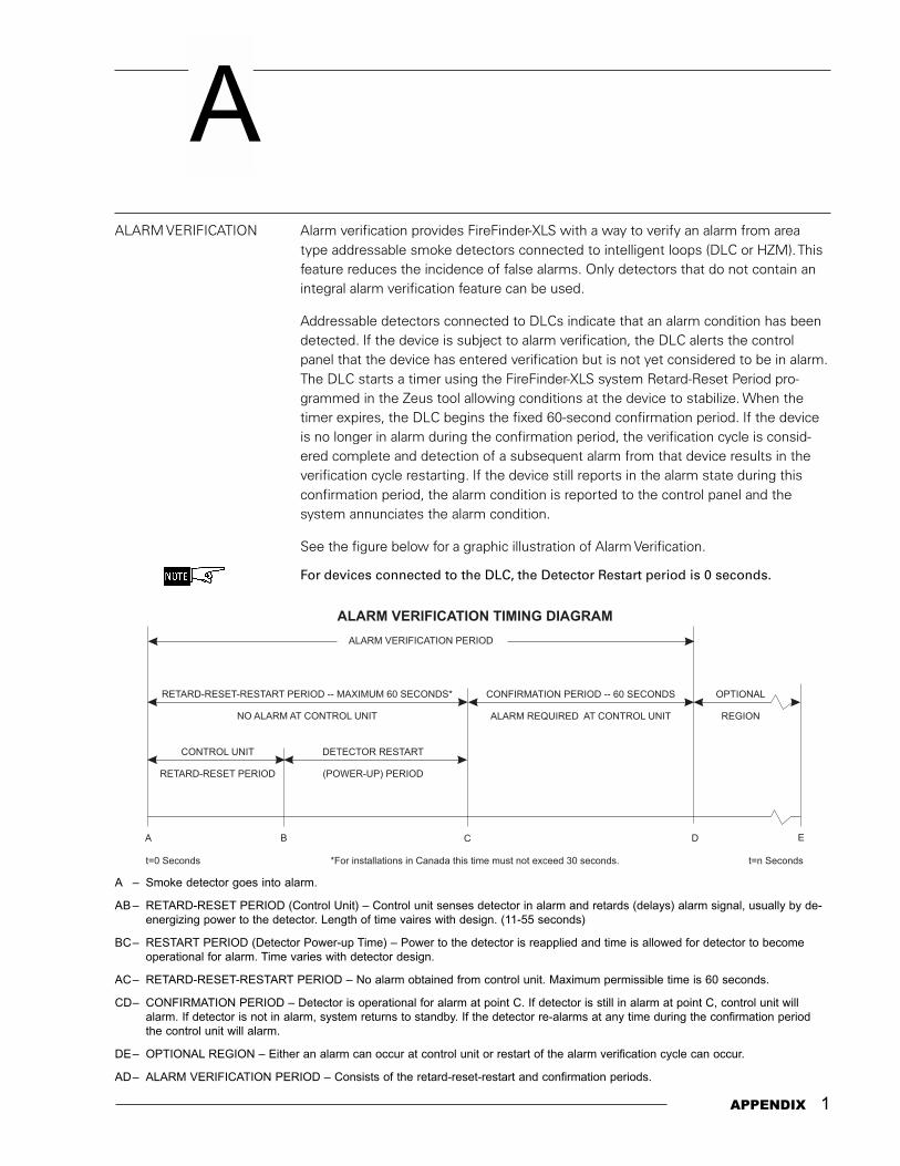
A
APPENDIX 1
ALARM VERIFICATION Alarm verification provides FireFinder-XLS with a way to verify an alarm from areatype addressable smoke detectors connected to intelligent loops (DLC or HZM). Thisfeature reduces the incidence of false alarms. Only detectors that do not contain anintegral alarm verification feature can be used.
Addressable detectors connected to DLCs indicate that an alarm condition has beendetected. If the device is subject to alarm verification, the DLC alerts the controlpanel that the device has entered verification but is not yet considered to be in alarm.The DLC starts a timer using the FireFinder-XLS system Retard-Reset Period pro-grammed in the Zeus tool allowing conditions at the device to stabilize. When thetimer expires, the DLC begins the fixed 60-second confirmation period. If the deviceis no longer in alarm during the confirmation period, the verification cycle is consid-ered complete and detection of a subsequent alarm from that device results in theverification cycle restarting. If the device still reports in the alarm state during thisconfirmation period, the alarm condition is reported to the control panel and thesystem annunciates the alarm condition.
See the figure below for a graphic illustration of Alarm Verification.
For devices connected to the DLC, the Detector Restart period is 0 seconds.
A � Smoke detector goes into alarm.
AB � RETARD-RESET PERIOD (Control Unit) � Control unit senses detector in alarm and retards (delays) alarm signal, usually by de-energizing power to the detector. Length of time vaires with design. (11-55 seconds)
BC� RESTART PERIOD (Detector Power-up Time) � Power to the detector is reapplied and time is allowed for detector to becomeoperational for alarm. Time varies with detector design.
AC� RETARD-RESET-RESTART PERIOD � No alarm obtained from control unit. Maximum permissible time is 60 seconds.
CD� CONFIRMATION PERIOD � Detector is operational for alarm at point C. If detector is still in alarm at point C, control unit willalarm. If detector is not in alarm, system returns to standby. If the detector re-alarms at any time during the confirmation periodthe control unit will alarm.
DE� OPTIONAL REGION � Either an alarm can occur at control unit or restart of the alarm verification cycle can occur.
AD� ALARM VERIFICATION PERIOD � Consists of the retard-reset-restart and confirmation periods.
ALARM VERIFICATION TIMING DIAGRAM
ALARM VERIFICATION PERIOD
RETARD-RESET-RESTART PERIOD -- MAXIMUM 60 SECONDS*
NO ALARM AT CONTROL UNIT
*For installations in Canada this time must not exceed 30 seconds.
CONFIRMATION PERIOD -- 60 SECONDS
ALARM REQUIRED AT CONTROL UNIT
OPTIONAL
REGION
A
t=0 Seconds t=n Seconds
B C D E
CONTROL UNIT
RETARD-RESET PERIOD
DETECTOR RESTART
(POWER-UP) PERIOD

2 APPENDIX
FIREFINDER-XLS INSTALLATION AND MAINTENANCE MANUAL | APPENDIX A
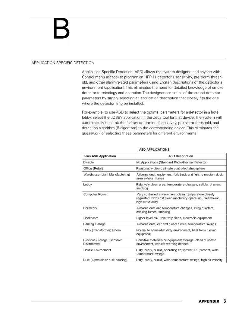
B
APPENDIX 3
APPLICATION SPECIFIC DETECTION
Application Specific Detection (ASD) allows the system designer (and anyone withControl menu access) to program an HFP-11 detector�s sensitivity, pre-alarm thresh-old, and other alarm-related parameters using English descriptions of the detector'senvironment (application). This eliminates the need for detailed knowledge of smokedetector terminology and operation. The designer can set all of the critical detectorparameters by simply selecting an application description that closely fits the onewhere the detector is to be installed.
For example, to use ASD to select the optimal parameters for a detector in a hotellobby, select the LOBBY application in the Zeus tool for that device. The system willautomatically transmit the factory determined sensitivity, pre-alarm threshold, anddetection algorithm (R-algorithm) to the corresponding device. This eliminates theguesswork of selecting these parameters for different environments.
SNOITACILPPADSA
noitacilppADSAsueZ noitpircseDDSA
elbasiD )rotceteDlamreht/otohPdradnatS(snoitacilppAoN
)liateR(eciffO erehpsomtadellortnocetamilc,naelcylbanosaeR
)gnirutcafunaMthgiL(esuoheraW kcodmuidemotthgildnakcurtkrof,tnempiuqe,tsudenrobriAsemuftsuahxeaera
ybboL ,senohpralullec,segnahcerutarepmet,aeranaelcylevitaleRgnikoms
mooRretupmoC ylesolcerutarepmet,naelc,tnemnorivnedellortnocyreV,gnikomson,gnitarepoyrenihcamnaelctsochgih,detaluger
yticolevriahgih
yrotimroD ,sretrauqgnivil,segnahcerutarepmetdnatsudenrobriAgnikoms,semufgnikooc
erachtlaeH tnempiuqecinortcele,naelcylevitaler,ksirlevelrehgiH
egaraGgnikraP sgniwserutarepmet,semufleseiddnarac,tsudenrobriA
mooR)remrofsnarT(ytilitU gninnurmorftaeh,tnemnorivneytridtahwemosotlamroNtnempiuqe
evitisneS(egarotSsuoicerP)tnemnorivnE
eerf-tsudnaelc,egarotstnempiuqeroslairetamevitisneSderisedgninrawtseilrae,tnemnorivne
tnemnorivnEelitsoH ediw,tneserpFR,tnempiuqegnitarepo,dimuh,ytsud,ytriDsgniwserutarepmet
)gnisuohtcudrorianepO(tcuD yticolevriahgih,sgniwserutarepmetediw,dimuh,ytsud,ytriD

4 APPENDIX
FIREFINDER-XLS INSTALLATION, OPERATION AND MAINTENANCE MANUAL | APPENDIX B
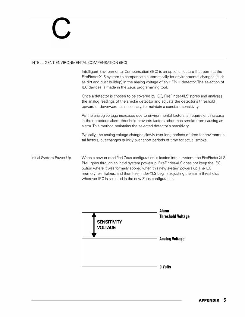
C
APPENDIX 5
INTELLIGENT ENVIRONMENTAL COMPENSATION (IEC)
Intelligent Environmental Compensation (IEC) is an optional feature that permits theFireFinder-XLS system to compensate automatically for environmental changes (suchas dirt and dust buildup) in the analog voltage of an HFP-11 detector. The selection ofIEC devices is made in the Zeus programming tool.
Once a detector is chosen to be covered by IEC, FireFinder-XLS stores and analyzesthe analog readings of the smoke detector and adjusts the detector�s thresholdupward or downward, as necessary, to maintain a constant sensitivity.
As the analog voltage increases due to environmental factors, an equivalent increasein the detector�s alarm threshold prevents factors other than smoke from causing analarm. This method maintains the selected detector�s sensitivity.
Typically, the analog voltage changes slowly over long periods of time for environmen-tal factors, but changes quickly over short periods of time for actual smoke.
Initial System Power-Up When a new or modified Zeus configuration is loaded into a system, the FireFinder-XLSPMI goes through an initial system power-up. FireFinder-XLS does not keep the IECoption where it was formerly applied when this new system powers up. The IECmemory re-initializes, and then FireFinder-XLS begins adjusting the alarm thresholdswherever IEC is selected in the new Zeus configuration.
AlarmThreshold Voltage
Analog Voltage
0 Volts
SENSITIVITYVOLTAGE
6 APPENDIX
FIREFINDER-XLS INSTALLATION, OPERATION AND MAINTENANCE MANUAL | APPENDIX C
Adjusting the AlarmThreshold When a NewZeus is Uploaded After FireFinder-XLS checks that the actual ID of a device with IEC agrees with Zeus,
it adjusts the detector�s alarm threshold according to the data stored. The firstadjustment occurs after 100 hours of data accumulation. In the case of power cyclingor resetting, adjustments begin within 90 seconds.
If a detector with IEC reports an alarm condition before the detector�s alarm thresh-old is adjusted, the alarm delays until the alarm threshold is adjusted. If the devicecontinues to report an alarm condition once its alarm threshold is adjusted, the alarmreports.
If the Zeus and the device ID do not agree, the IEC for that device does not activateuntil the trouble condition is removed from the system and the panel is reset.
Ongoing Adjustments ofthe Alarm Threshold Environmental conditions usually cause a small change in the analog voltage over a
long period of time. At regular intervals FireFinder-XLS collects analog data for eachdetector with IEC and adjusts the alarm threshold accordingly. FireFinder-XLS adjustsfor both up and down changes in the analog voltage. In addition, if system power islost, FireFinder-XLS adjusts the alarm thresholds as needed by using stored data.
IEC Trouble Conditions A trouble condition involving the IEC may be annunciated by the FireFinder-XLS PMIas:
PRE-DIRTY ANALOG VOLT. REACHED
OR
IEC LIMIT REACHED. SERVICE REQ
The trouble conditions shown above are annunciated on a detector-by-detector basisas each detector is checked.
FireFinder-XLS annunciates a trouble condition for a detector when its alarm thresholdreaches a predetermined limit. The operator should acknowledge the trouble, cleanthe detector if possible, and reset the control panel. If the detector is not cleaned, thecontrol panel annunciates this trouble condition after every panel reset until thedetector is cleaned.
D
APPENDIX 7
These circuits are intended for 24 hour alarm monitoring only.
UL 1076 requires an HTSW-1 tamper switch as well as a PAL-1 printer. Only ModelsHTRI-S/-D/-R may be used as security points. A COMMUNICATION FAILURE with anHTRI device configured for SECURITY results in a SECURITY EVENT as well as acommunication trouble. When installing an HTRI device in the Zeus tool, be sure toset the device usage to security; otherwise, the device usage defaults to fire alarm.
� When setting the device address using the DPU, select the normally closedalarm causing input.
� Connect only one switch per HTRI input.
For proprietary burglaryapplication (UL 1076):
� Use an HTSW-1 tamper switch to monitor the main enclosure.
� Monitor each HTRI-S/-D/-R related to this application for 24 hours by using alisted motion detector (to prevent tampering).
� Monitoring of security points is performed at the PMI. The PMI is suitablefor installation at either the protected premises or remotely as a receivingunit.
SECURITY POINT INSTALLATION
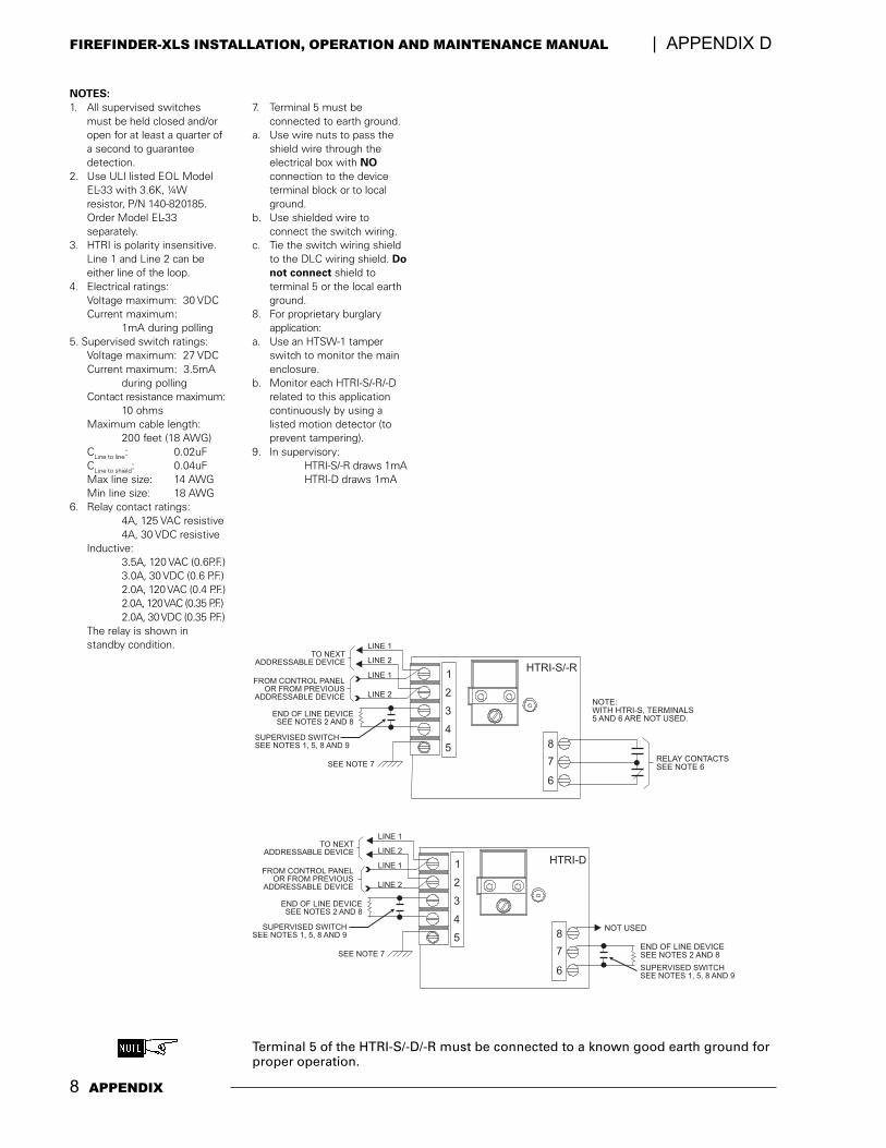
8 APPENDIX
FIREFINDER-XLS INSTALLATION, OPERATION AND MAINTENANCE MANUAL | APPENDIX D
TO NEXTADDRESSABLE DEVICE
END OF LINE DEVICESEE NOTES 2 AND 8
RELAY CONTACTSSEE NOTE 6
NOTE:WITH HTRI-S, TERMINALS5 AND 6 ARE NOT USED.
SUPERVISED SWITCHSEE NOTES 1, 5, 8 AND 9
FROM CONTROL PANELOR FROM PREVIOUS
ADDRESSABLE DEVICE
1HTRI-S/-R
2
3
4
5 8
7
6
LINE 1
LINE 1
LINE 2
LINE 2
SEE NOTE 7
NOTES:1. All supervised switches
must be held closed and/oropen for at least a quarter ofa second to guaranteedetection.
2. Use ULI listed EOL ModelEL-33 with 3.6K, ¼Wresistor, P/N 140-820185.Order Model EL-33separately.
3. HTRI is polarity insensitive.Line 1 and Line 2 can beeither line of the loop.
4. Electrical ratings:Voltage maximum: 30 VDCCurrent maximum:
1mA during polling5. Supervised switch ratings:
Voltage maximum: 27 VDCCurrent maximum: 3.5mA
during pollingContact resistance maximum:
10 ohmsMaximum cable length:
200 feet (18 AWG)CLine to line: 0.02uFCLine to shield: 0.04uFMax line size: 14 AWGMin line size: 18 AWG
6. Relay contact ratings:4A, 125 VAC resistive4A, 30 VDC resistive
Inductive:3.5A, 120 VAC (0.6P.F.)3.0A, 30 VDC (0.6 P.F.)2.0A, 120 VAC (0.4 P.F.)2.0A, 120 VAC (0.35 P.F.)2.0A, 30 VDC (0.35 P.F.)
The relay is shown instandby condition.
7. Terminal 5 must beconnected to earth ground.
a. Use wire nuts to pass theshield wire through theelectrical box with NOconnection to the deviceterminal block or to localground.
b. Use shielded wire toconnect the switch wiring.
c. Tie the switch wiring shieldto the DLC wiring shield. Donot connect shield toterminal 5 or the local earthground.
8. For proprietary burglaryapplication:
a. Use an HTSW-1 tamperswitch to monitor the mainenclosure.
b. Monitor each HTRI-S/-R/-Drelated to this applicationcontinuously by using alisted motion detector (toprevent tampering).
9. In supervisory:HTRI-S/-R draws 1mAHTRI-D draws 1mA
Terminal 5 of the HTRI-S/-D/-R must be connected to a known good earth ground forproper operation.
HTRI-D
NOT USED
TO NEXTADDRESSABLE DEVICE
END OF LINE DEVICESEE NOTES 2 AND 8
END OF LINE DEVICESEE NOTES 2 AND 8
SUPERVISED SWITCHSEE NOTES 1, 5, 8 AND 9
SUPERVISED SWITCHSEE NOTES 1, 5, 8 AND 9
FROM CONTROL PANELOR FROM PREVIOUS
ADDRESSABLE DEVICE
1
2
3
4
5 8
7
6
LINE 1
LINE 1
LINE 2
LINE 2
SEE NOTE 7
E
APPENDIX 9
SILENT KNIGHT MODEL 5129
Electrical Connections The FireFinder-XLS system connects to the Silent Knight Model 5129 Digital FireCommunicator using the Alarm, Trouble, and Supervisory dry contacts on the PSC-12.
Refer to the Silent Knight 5129 Fire Slave Communicator Installation Manual, P/N150805, provided with Silent Knight Model 5129 for dialer instructions.
The Silent Knight Model 5129 monitors all System troubles through the PSC-12trouble relay. FireFinder-XLS delays the AC fail trouble signal in accordance with NFPAand UL requirements.
In NFPA 72 Remote Station install batteries to provide 60 hour standby capacity. Forsignalling service DACT wire according to the diagram on the following page.
In NFPA 72 Central Station connections AC fail reporting is delayed. The delay is 6hours (25% of 24 hours) for NFPA, Local and Proprietary, and 15 hours (25% of 60hours) for NFPA Remote Station. Only the reporting of the trouble is delayed.
AC power must be present for a full minute before the system switches back to ACpower from the battery.
Using the optional AC monitor input, the Silent Knight Model 5129 monitors AC failtrouble. When the FireFinder-XLS system reports an AC fail trouble, the Silent KnightModel 5129 sends a specific code to the Central Station that identifies the trouble asAC fail.
Mounting The Silent Knight Model 5129 is shipped with an enclosure. Mount the 5129 within20 feet of the enclosure containing the PSC-12 and connect it with rigid condiut.
Electrical Ratings Supervisory 18-40 VDC60mA
Alarm 18-40 VDC130mA
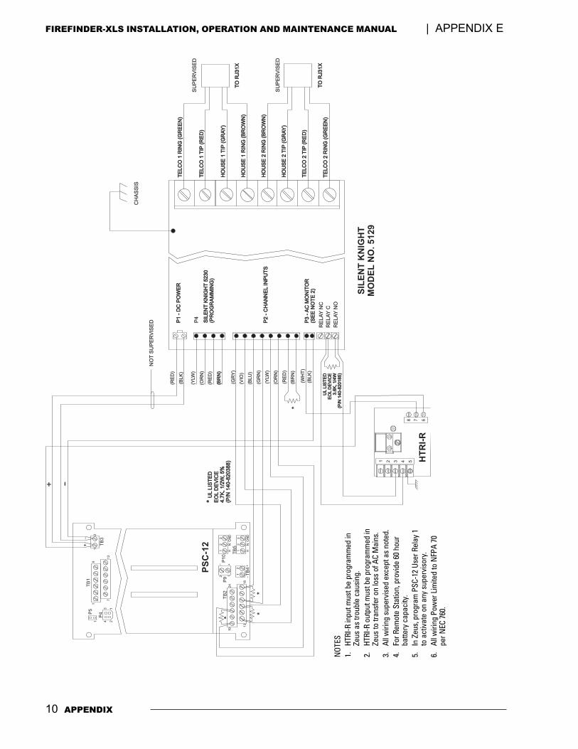
10 APPENDIX
FIREFINDER-XLS INSTALLATION, OPERATION AND MAINTENANCE MANUAL | APPENDIX E
NOT
ES1.
HTRI
-R in
put m
ust b
e pr
ogra
mm
ed in
Zeus
as
troub
le c
ausi
ng.
2.HT
RI-R
out
put m
ust b
e pr
ogra
mm
ed in
Zeus
to tr
ansf
er o
n lo
ss o
f AC
Mai
ns.
3.Al
l wiri
ng s
uper
vise
d ex
cept
as
note
d.4.
For R
emot
e St
atio
n, p
rovi
de 6
0 ho
urba
ttery
cap
acity
.5.
In Z
eus,
pro
gram
PSC
-12
User
Rel
ay 1
to a
ctiv
ate
on a
ny s
uper
viso
ry.
6.Al
l wiri
ng P
ower
Lim
ited
to N
FPA
70pe
r NEC
760
.
P1
-D
CP
OW
ER
P1
-D
CP
OW
ER
P4
P3
-A
CM
ON
ITO
R(S
EE
NO
TE
2)
P3
-A
CM
ON
ITO
R(S
EE
NO
TE
2)
RE
LA
YN
C
RE
LA
YC
RE
LA
YN
O
(RE
D)
TE
LC
O1
RIN
G(G
RE
EN
)T
EL
CO
1R
ING
(GR
EE
N)
TE
LC
O1
TIP
(RE
D)
TE
LC
O1
TIP
(RE
D)
HO
US
E1
TIP
(GR
AY
)H
OU
SE
1T
IP(G
RA
Y)
HO
US
E1
RIN
G(B
RO
WN
)H
OU
SE
1R
ING
(BR
OW
N)
HO
US
E2
RIN
G(B
RO
WN
)H
OU
SE
2R
ING
(BR
OW
N)
HO
US
E2
TIP
(GR
AY
)H
OU
SE
2T
IP(G
RA
Y)
TE
LC
O2
TIP
(RE
D)
TE
LC
O2
TIP
(RE
D)
TE
LC
O2
RIN
G(G
RE
EN
)T
EL
CO
2R
ING
(GR
EE
N)
(BLK
)
SIL
EN
TK
NIG
HT
52
30
(PR
OG
RA
MM
ING
)S
ILE
NT
KN
IGH
T5
23
0(P
RO
GR
AM
MIN
G)
P2
-C
HA
NN
EL
INP
UT
SP
2-
CH
AN
NE
LIN
PU
TS
(GR
Y)
(YLW
)
(VIO
)
(OR
N)
(BLU
)
(RE
D)
(GR
N)
(BR
N)
(BR
N)
(YLW
)
(OR
N)
(RE
D)
(BR
N)
(BLK
)
(WH
T)
SU
PE
RV
ISE
D
SU
PE
RV
ISE
D
TO
RJ31X
TO
RJ31X
TO
RJ31X
TO
RJ31X
SIL
EN
TK
NIG
HT
MO
DE
LN
O.
51
29
CH
AS
SIS
PS
C-1
2
HT
RI-
R
NO
TS
UP
ER
VIS
ED
+ -
UL
LIS
TE
DE
OL
DE
VIC
E3
.6K
,1
/4W
(P/N
14
0-8
20
18
5)
UL
LIS
TE
DE
OL
DE
VIC
E3
.6K
,1
/4W
(P/N
14
0-8
20
18
5)
*U
LLIS
TE
D
EO
LD
EV
ICE
4.7
K,1/2
W,5%
(P/N
140-8
20388)
*U
LLIS
TE
D
EO
LD
EV
ICE
4.7
K,
1/2
W,
5%
(P/N
140-8
20388)
*
19
1
++
_
_
21 H
2 N
3
GN
D
1 H
2 N
3
GN
D12
24
18
13
TB
2P
9P
10
TB
5
TB
4
1 2 3 4 58 7 6
P5
11
1
+_
26
12
71
2
34
TB
1
TB
3P
4
*
**
F
APPENDIX 11
TESTING / MAINTENANCE If the system is connected to the fire department, etc., or actuates an internalsystem, disarm the appropriate outputs before servicing to prevent actuation. (SeePMI Operation for procedures.) Notify the fire department and personnel at yourfacility that a System test is being performed so that any alarm sounding can beignored during the test. Notify the fire department before resetting the system.
Inspection, Testing, and Maintenance of the fire alarm system should be peformed inaccordance with NFPA 72, The National Fire Alarm Code and all applicable local codes.

12 APPENDIX
FIREFINDER-XLS INSTALLATION, OPERATION AND MAINTENANCE MANUAL | APPENDIX F
APPENDIX 13
TROUBLE MESSAGES The trouble messages for the FireFInder-XLS system will be displayed on the PMI. Upto five trouble messages may be displayed on the screen at one time. Each troublemessage will show the TIME that the trouble occured, the SOURCE of the troubleand the TYPE of trouble.
The trouble LED will flash whenever new troubles are reported and will turn steadywhen the troubles have been acknowledged by pressing the appropriate button onthe PMI.
G
EGASSEM NOITPIRCSED
ylppuSpma21V42nwodtuhS
eudnwodtuhssahtuptuodetimilrewop-nonpma21tlov42ehttahtsetacidnI.daolrevoot
nwodtuhSylppuSpma4V42 tuptuodetimilrewopehtseilppustahtylppuspma4tlov42ehttahtsetacidnI.daolrevooteudnwodtuhssah
detceteDtuonworBCA ehtwolebnellafevahXSProCSPehtgnideefsniamCAehttahtsetacidnI.dlohserhttuonworb
liaFCA .detcennocsideraXSProCSPehtgnideefsniamCAehttahtsetacidnI
nwodtuhSrewoPenalpkcaB nwodtuhssahenalpkcabehtseilppustahtylppustlov2.6ehttahtsetacidnI.daolrevooteud
nepOgniriW/esuFyrettaB .neposiyrettabehtotgnitcennocrekaerbtiucricehT
tluaFAssalC .poolAssalCanodetcetedneebsahtluafA
rorrEsnoitacinummoC TENDrosubNACroISAehtnotluafasetacidnI
demrasiD narotupninatahtrotarepoehtotrednimerasadetarenegsiegassemsihT.demrasidneebsahtuptuo
tluaFdnuorG .eludomehtotgniriwehtnotluafdnuorgasetacidnI
suniMtluaFdnuorG .ylppusrewopehtfoedissunimehtnodnuorgotnoitcennocA
sulPtluaFdnuorG .ylppusrewopehtfoedissulpehtnidnuorgotnoitcennocA
DItcerrocnI .sserddanatadecalpsieludomtcerrocniehtnehwdeyalpsidsI
woLooTegatloVtupnI .wolootsiCIZehtfotupniehtnoegatlovehT
egatloVyrettaBwoL .wolsiyrettabehtnoegatlovehttahtsetacidnI
elbuorTtupnICIM neebsahrodeliafsahenohporcimehtfonoisivrepusehttahtsetacidnI.detcennocsid
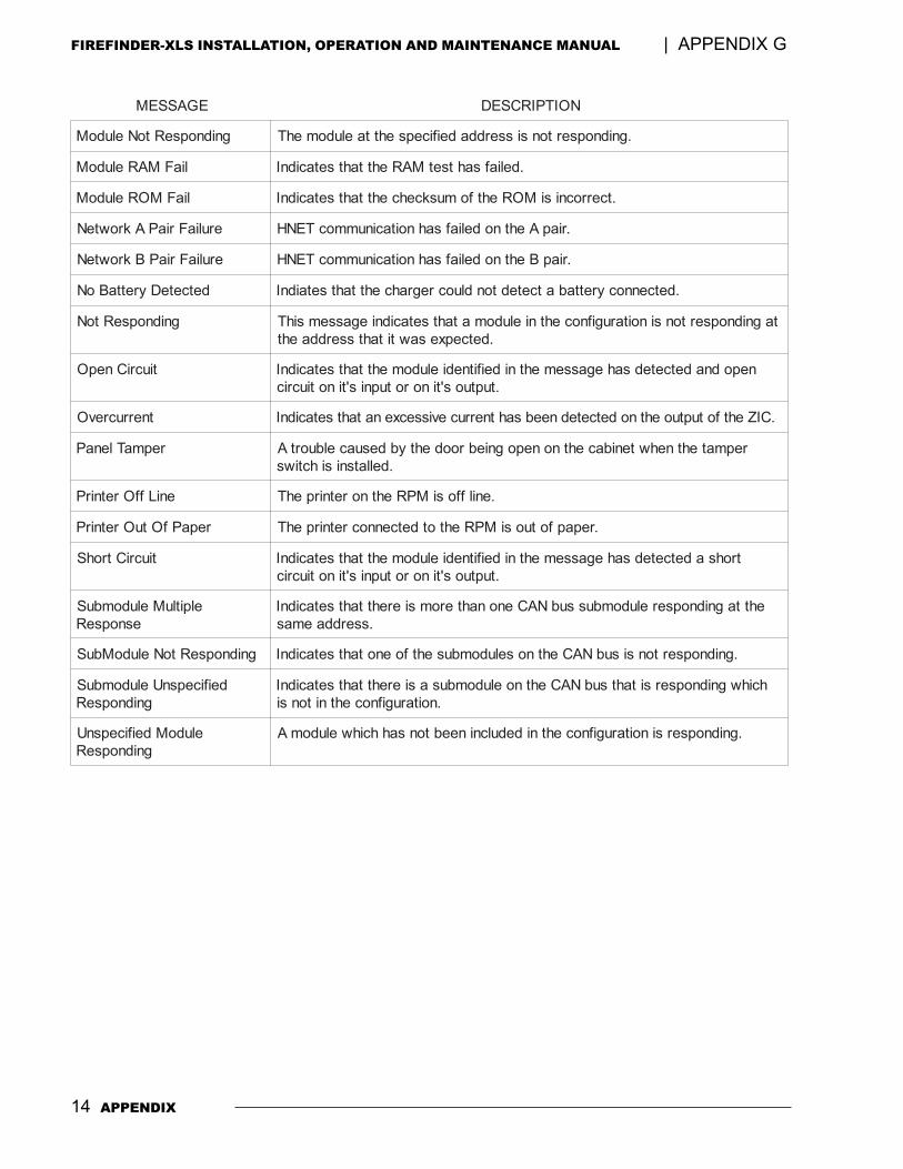
14 APPENDIX
FIREFINDER-XLS INSTALLATION, OPERATION AND MAINTENANCE MANUAL | APPENDIX G
EGASSEM NOITPIRCSED
gnidnopseRtoNeludoM .gnidnopsertonsisserddadeificepsehttaeludomehT
liaFMAReludoM .deliafsahtsetMARehttahtsetacidnI
liaFMOReludoM .tcerrocnisiMORehtfomuskcehcehttahtsetacidnI
eruliaFriaPAkrowteN .riapAehtnodeliafsahnoitacinummocTENH
eruliaFriaPBkrowteN .riapBehtnodeliafsahnoitacinummocTENH
detceteDyrettaBoN .detcennocyrettabatcetedtondluocregrahcehttahtsetaidnI
gnidnopseRtoN tagnidnopsertonsinoitarugifnocehtnieludomatahtsetacidniegassemsihT.detcepxesawtitahtsserddaeht
tiucriCnepO nepodnadetcetedsahegassemehtnideifitnedieludomehttahtsetacidnI.tuptuos'tinorotupnis'tinotiucric
tnerrucrevO .CIZehtfotuptuoehtnodetcetedneebsahtnerrucevissecxenatahtsetacidnI
repmaTlenaP repmatehtnehwtenibacehtnonepogniebroodehtybdesuacelbuortA.dellatsnisihctiws
eniLffOretnirP .enilffosiMPRehtnoretnirpehT
repaPfOtuOretnirP .repapfotuosiMPRehtotdetcennocretnirpehT
tiucriCtrohS trohsadetcetedsahegassemehtnideifitnedieludomehttahtsetacidnI.tuptuos'tinorotupnis'tinotiucric
elpitluMeludombuSesnopseR
ehttagnidnopsereludombussubNACenonahteromsierehttahtsetacidnI.sserddaemas
gnidnopseRtoNeludoMbuS .gnidnopsertonsisubNACehtnoseludombusehtfoenotahtsetacidnI
deificepsnUeludombuSgnidnopseR
hcihwgnidnopsersitahtsubNACehtnoeludombusasierehttahtsetacidnI.noitarugifnocehtnitonsi
eludoMdeificepsnUgnidnopseR
.gnidnopsersinoitarugifnocehtnidedulcnineebtonsahhcihweludomA
INDEX | FIREFINDER-XLS INSTALLATION, OPERATION AND MAINTENANCE MANUAL
Index - 1
IndeIndeIndeIndeIndexxxxxAAAAAAcknowledge 3-3Acknowledge supervisory 3-5Acknowledge trouble 3-6AIC audio input card 1-9Alarm 3-3Alarm verification Appendix-1Alert mode 3-3 to 3-6, 4-10
Alarm 3-3All Alert 4-10display 4-15preview 4-17Security 3-5Select Alert 4-10Supervisory 3-5Trouble 3-5
Alert signal 4-3All Alert 4-10All Background Music 4-12All Convenience Page 4-10All Evacuation 4-9All Page 4-4Application Specific Detection. See ASDASD Appendix-3audible silence 4-13audible unsilence 4-13audio volume control 4-18
background music volume down 4-20background music volume up 4-19convenience page volume down 4-19convenience page volume up 4-18
BBBBBbackground music 4-3, 4-12 to 4-13
All Background Music 4-12display 4-16preview 4-18Select Background Music 4-12volume 4-19
basic FireFinder-XLS system 1-1, 1-3Batteries 1-3, 1-6BP-61 battery 1-3, 1-6BTX-1 batteries 1-3, 1-6BTX-2 batteries 1-3, 1-6BTX-3 batteries 1-3, 1-6
CCCCCCAB-MP mounting plate 2-1CAB1 enclosure 1-3, 1-6CAB2 enclosure 1-6CAB3 enclosure 1-6, 2-3CAN-BUS 1-10CC-2 card cage 1-5, 2-1CC-5 card cage 1-1, 1-3, 1-4, 2-1clear manual 4-21command station access 4-20
deny 4-20grant 4-20request 4-20status 4-20
command stations 4-1convenience page 4-3, 4-10 to 4-12
All Convenience Page 4-10display 4-16preview 4-18Select Convenience Page 4-11volume 4-18
CRC-6 relay module 1-6CSB CAN sounder board 1-7
DDDDDDAC-NET 1-10, 4-1detector sensitivities. See sensitivity reportdetectors. See intelligent analog devicesDLC device loop card 1-1, 1-3, 1-5, 2-4, Appendix-
1DPU device programming unit 1-13, 2-3
EEEEEemergency page 4-3, 4-4 to 4-9
All Page 4-4Page to Alert 4-7Page to Background Music 4-8Page to Evacuation 4-6Select Page 4-5
enclosures 1-6, 2-1, 2-2CAB1 1-3, 1-6CAB2 1-6CAB3 1-6, 2-3REMBOX 2/4 1-8
FIREFINDER-XLS INSTALLATION, OPERATION AND MAINTENANCE MANUAL | INDEX
Index - 2
evacuation signal (EVAC) 4-3, 4-9All Evacuation 4-9display 4-15preview 4-17Select Evacuation 4-9
FFFFFFCM-6 control module 1-7Firefighter's mode. See Alert modeFirefighters' telephone system 4-21 to 4-22
phone group 4-21phone page 4-22warden's page 4-22
FMT fireman's master telephone 1-10, 4-1FTS Series firefighter's telephone stations 1-10
GGGGGgroups 3-4
HHHHHhard reset 3-6help 3-2HFP-11 intelligent/analog photoelectric detector 1-
12HFPT-11 intelligent thermal detector 1-12HLIM loop isolator module 1-7, 1-12HMS-2S/-SA intelligent manual station 1-13HMS-M intelligent manual station (metal) 1-13HMS-S/-D intelligent manual station 1-13HTRI-M intelligent interface module 1-13HTRI-S/-R/-D intelligent interface modules 1-
13, Appendix-7HTSW-1 tamper switch 1-3, 1-6, 2-1, Appendix-7HZM remote conventional zone module 1-13
IIIIIIEC Appendix-5intelligent analog devices 1-12 to 1-13
HFP-11 intelligent/analog photoelectric detector1-12
HFPT-11 intelligent thermal detector 1-12HLIM loop isolator module 1-12HMS-2S/-SA intelligent manual station 1-13HMS-M intelligent manual station (metal) 1-13HMS-S/-D intelligent manual station 1-13HTRI-M intelligent interface module 1-13HTRI-S/-R/-D intelligent interface modules 1-13HZM remote conventional zone module 1-13
Intelligent environmental compensation. See IEC
LLLLLlamp test 4-21LCM-8 LED control module 1-7LEDs 1-4, 3-1, 4-4LPB local page board 1-10, 4-1LVM live voice module 1-11, 4-1, 4-4
MMMMMmaintenance Appendix-11manual station. See intelligent analog devicesmap 3-4menu 3-2minimum configuration 1-2More Info (+ / -) 3-2, 3-3More Info button 1-1
NNNNNnavigation buttons 1-4NFPA 72 Central Station Appendix-9NFPA 72 Remote Station Appendix-9NIC-C network interface card 1-1, 1-7Normal mode 3-2
OOOOOOCM-16 output control 1-8optional modules 1-6 to 1-7
PPPPPPage. See emergency page
preview 4-17Page to Alert 4-7Page to Background Music 4-8Page to Evacuation 4-6PAL-1 printer Appendix-7PFT Series firefighter's telephones 1-11phone group 4-21phone page 4-22PMI person machine interface 1-1, 1-3 to 1-4, 2-
1, 3-1, Appendix-13PMI-REM remote PMI 1-8PSC-12 power supply 1-1, 1-3, 1-4, 1-8, 2-2, Ap-
pendix-9PTB power termination board 1-1, 1-3, 1-5, 2-2
RRRRRREMBOX 2/4 remote enclosures 1-8Reporting detector sensitivities 3-6Reports
Configuration 3-7History 3-7Queue 3-7
INDEX | FIREFINDER-XLS INSTALLATION, OPERATION AND MAINTENANCE MANUAL
Index - 3
Reset system 3-3, 3-6RNI remote network interface 1-8RPM remote printer module 1-3, 1-6
SSSSSSCM-8 switch control 1-9, 4-1, 4-4Scroll UP / Scroll DOWN 3-2Security 3-5security point Appendix-7Select Alert 4-10Select Background Music 4-12Select Convenience Page 4-11Select Evacuation 4-9Select Page 4-5sensitivity report 3-7silence individual 4-14
cancel 4-14Silent Knight Model 5129 Appendix-9SIM-16 supervised input 1-9soft keys 1-4, 3-1
acknowledge 3-3acknowledge supervisory 3-5acknowledge trouble 3-6map 3-4reset system 3-3status 3-7
soft reset 3-6speaker groups 4-13 to 4-20
audible silence / unsilence 4-13audio to local speaker 4-17display 4-14
alert 4-15auto 4-14background music 4-16convenience page 4-16evacuation 4-15silenced 4-15
non-silence 4-14preview
alert 4-17background music 4-18convenience page 4-18evacuation 4-17page 4-17
select audio preview 4-16SSD system status display 1-9Status report 3-7
Sensitivity 3-7Supervisory 3-5system priorities 4-3
TTTTTtesting Appendix-11touch screen 3-2Trouble 3-5trouble messages Appendix-13TZC-8B 1-11, 4-1
VVVVVVGA display 1-1, 1-4, 3-1voice system modules 1-9 to 1-12
AIC audio input card 1-9DAC-NET 1-10FMT fireman's master telephone 1-10FTS Series Firefighter's Telephone Stations 1-10LPB local page board 1-10LVM live voice module 1-11PFT Series Firefighter's Telephones 1-11TXC-8B telephone zone card 1-11
voice system operation 4-2audible silence 4-13audible unsilence 4-13audio volume control 4-18automatic 4-2
Alert signal 4-3evacuation signal 4-3
cancel silence individual 4-14firefighters' telephopne system 4-21 to 4-22lamp test 4-21manual 4-3
Alert signal 4-3, 4-10background music 4-3, 4-12 to 4-13clear 4-21convenience page 4-3, 4-10 to 4-12emergency page 4-3, 4-4 to 4-9evacuation signal (EVAC) 4-3, 4-9
priorities 4-3silence individual 4-14speaker groups 4-13 to 4-20
volume control. See audio volume control
WWWWWWarden's page 4-22
ZZZZZZAC-40 zone amplified card 1-11, 4-1ZAM-180 zone amplifier 1-12Zeus programming tool 1-2, 2-4, 3-2, 3-3, 3-
4, Appendix-3ZIC-4A zone indicating card 1-1, 1-3, 1-5, 4-1

FIREFINDER-XLS INSTALLATION, OPERATION AND MAINTENANCE MANUAL | INDEX
Index - 4


Siemens Building Technologies, Inc.8 Fernwood RoadFlorham Park, New Jersey 07932
Siemens Building TechnologiesFire Safety
Siemens Building Technologies, Ltd.2 Kenview BoulevardBrampton, Ontario L6T 5E4 CN
P/N 315-033744-3
Related Documents