MANUAL 3-Phase-Transistor-Servo-Drive for AC-Synchro-Servomotors with Resolver TVD6.2-RS G m b H Industriestraße 1 D-71397 Leutenbach 3 - Nellmersbach

Welcome message from author
This document is posted to help you gain knowledge. Please leave a comment to let me know what you think about it! Share it to your friends and learn new things together.
Transcript
MANUAL
3-Phase-Transistor-Servo-Drivefor
AC-Synchro-Servomotors
with
Resolver
TVD
6.2
-RS
Version0899-1
G m b H
Industriestraße 1
D-71397 Leutenbach 3 - Nellmersbach

Transistor-Servo-Drive TVD6.2-RS
2
1 Basic-Information SeiteSafety Advice 3General Information 4Application 5Characteristics 6Technical Data 7
2 Mechanical InstallationDimensions 8, 9Structure of Device 10Mounting Advice 11
3 Electrical InstallationConnection Overview 12Connection Plan 13Earthing Plan EMC-Advice 14Mains Connection 15,16Motor Connection 17Control Connection 18 to 23Signals 24, 25Connector Plan 26, 27, 28
4 Device OverviewResolver 29Component Positions 30Block Diagram 31Frontpanel 32Adjustment Functions 33Signals 34
5 AdjustmentAdjustment Advice 35Nominal Value 36Actual Value 37Current 38Speed Controller 39 to 41
6 Getting StartedDefault Setup 42Getting Started 43
7 Fault FindingLED Indications 44Function Faults 45Function Diagram 46Encoder Signals 47
8 Guarantee 48
9 Protocol 49
Con
tent

TVD6.2-400-x-RS 3
Electronic devices always involve the risk of failure.
This manual has to be read carefully and must be understoodby experts before installing or starting the device.If there are any doubts call your trader or the manufacturer.
The TVD6 series is designed to regulate electrical currents;protection standard IP00.
Instructions and rules:
the devices and accessory components must be set up and connected ac-cording to the local technical regulations. In Germany they are:- EU-machine guide lines 89/392/EWG,84/528/EWG,86/663/EWG- VDE-regulation VDE 100, VDE 110, VDE 160 und VDE 0113- TÜV-regulations- Regulations of the professional guild.
The user has to assure that:
after- a failure of the device- an incorrect handling- a failure of the control unit etc.
t
he drive is brought to a secure operating condition.Machines and installations are to be provided with supervisory and safetyequipment, that is independent of the device.
Adjustment
- only by qualified personnel- adher to safety regulations
Installation work
- only when disconnected from all power lines.QS
The devices are archived by the manufacturer with serial number and theirtest specifications.CE
The EU-guide line 89/336/EWG with the EMC-Regulations EN50081-2 andEN50082-2 are observed.
Caution High Voltage
AC 460V~, DC 750V=
1Basic-Information
Safe
tyA
dvi
ce

Transistor-Servo-Drive TVD6.2-RS
4
The transistor 3-phase current servo amplifier SERVO-TVD6.2 forms toget-her with the brushless direct current motor (synchro-servo (EC-) motor) apropulsion unit distinguished by its rear-zero maintenance and by its highdynamic control range.The drive displays the wellknown good regulation characteristics of thedirect current drives without the disadvantages of the carbon brush wearand of the communication limits.The rotor intertia is notably lower and the power envelope is greaterthan with equally constructed DC-motors. The result are up to 5 timeshigher acceleration values. As the generated heat in the motor occurs inthe stator, the ec-motors are always designed to the protection standard IP65.The brushless direct current motor is electrically a synchro-motor with apermanent magnet rotor and 3-phase stator.The physical characteristics correspond to those of the direct currentmotors, that is, the current is proportional to the torque and the voltage isproportional to the speed. As both values can be measured precisely, theservo-control unit can be mounted easily. It is possible to control the speedfrom the motor voltage, but in order to achieve exact regulation it is prefe-rable touse atways a tachometer regulation.
The tachometer actual value is generated from the sensor unit (resolver).In the speed controller (P-I-controller) of the servo-drive is the differenz ofnominal value and actual value amplified. The result is the current nomi-nal value, which is transferred by the resolver signal onto the three phasecurrent controllers such that the stator magnetic field leads ca. 90° electri-cally the rotor magnetic field.This field frequency is not a controlled variable, it adjusts istself automati-cally. The motor currents, following the resolver interpretation, form a si-ne-waved rotating field.As occurs in all DC-, AC or ec-servo-amplifiers which are supplied by thedc-bus, the feed-back of the energy must be observed when braking in thedc-bus (especially where stroke or eccentric cycles are concerned). Thebleeder switch is set for a 3 % duty cycle. The ballast-resistors have to bemounted externally.Information:
For lower power >>> UNITEK Serie TVD3.2100V upto 10/20A
For higher power >>> UNITEK Serie MODULA400V upto 100/200A
Gen
eral
Info
rmatio
n
TVD6.2-400-x-RS 5
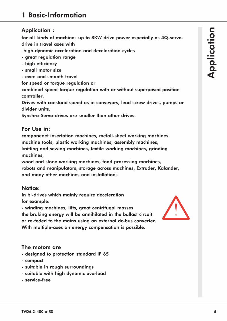
Application :
for all kinds of machines up to 8KW drive power especially as 4Q-servo-drive in travel axes with-high dynamic acceleration and deceleration cycles- great regulation range- high efficiency- small motor size- even and smooth travelfor speed or torque regulation orcombined speed-torque regulation with or without superposed positioncontroller.Drives with constand speed as in conveyors, lead screw drives, pumps ordivider units.Synchro-Servo-drives are smaller than other drives.
For Use in:componenet insertation machines, metall-sheet working machinesmachine tools, plastic working machines, assembly machines,knitting and sewing machines, textile working machines, grindingmachines,wood and stone working machines, food processing machines,robots and manipulators, storage across machines, Extruder, Kalander,and many other machines and installations
Notice:In bl-drives which mainly require decelerationfor example:- winding machines, lifts, great centrifugal massesthe braking energy will be annihilated in the ballast circuitor re-feded to the mains using an external dc-bus converter.With multiple-axes an energy compensation is possible.
The motors are- designed to protection standard IP 65- compact- suitable in rough surroundings- suitable with high dynamic overload- service-free
1 Basic-Information
Ap
plic
ation

Transistor-Servo-Drive TVD6.2-RS
6
Construction:- cubicle-mount or 6HE-plug-in unit according to the
VDE- DIN- and EU- regulations.- standard analog regulation electronics.- power electronics for 5A, 10A, 16A and 25A.- wide-band chopper supply unit for the auxiliary voltages.- power supply unit on the back circuit board .
Galvanic isolation between- power section and covering- power section and regulation electronics- regulation electronics and contol inputsThe leakage distances are according to the VDE regulations.
There are used:- fully isolated six-pack IGBT-power semiconductors, generous
dimensioning.- only industrial standard components are used- All ICs with external connections are mouted on high-quality sockets- LED displays- 16 digit binary switches for PI-setup of the speed regulator- precision trimers for fine adjustment- plug-in jumpers for system setup.
Characteristics:* Direct power supply 400V~* Electronic starting current limitation* 2 differential reference inputs* Accelleration and decelleration ramp with second nominal value* Speed and torque regulation* Static and dynamic current limit* Current nominal value output* Test connectors for current and speed* Galvanic isolated logic in- and outputs* Enable and end-switch logic* Integral disabling* Quick stop* Mains failure braking* Temperature control for motor and device* Parameter adjustments without soldering* 10 pin control plug* Incremental encoder output
Ch
ara
cteristic

TVD6.2-400-x-RS 7
Power connection:directly on the mains 1x 400V~
3x 400V~maximum: 460V~
Option :connection voltage < 300V~ >>> notice the advise
Technical data:type TVD6.2-400- 5 10 16 25output voltage max. V~eff. 400 400 400 400output standstill currentduration A= 5 10 16 25peak A= 10 20 32 40electrical power max kW 2 4 6,4 10rapid fusesbuilt-in A 20 20 20 20measurementsplug-in device BxH 16TE 16TE 16TE 24TE 6HE
cooling 60% ED convect convect fan fan100% ED convect fan fan
fanswitch cabinet mounting BxHxT see illustrations of the dimensions
Common specifications:protection standard IP 00device layout VDE 0100 group C
VDE 0160humidity stress class F according to DIN 40040operation altitude < 1000m above NNoperation range 0 ... 45°C (with external fan 0 ... 35°C)expanded operation range up to 60° C red. 2%/ °Cbearing reach -30°C up to + 80°C
speed controllercontrol precision (excl. tacho error) ± 0,1%control range > 1: 1000
reference inputs ± 10V=logic inputs +10 ... +30V=logic outputs >+14V, 6mA
Caution:
When order please specify:
notice cyclic duration factor >>> external cooling system with 100%
several axes with >=10A
within one rack >>> external cooling system recommendedinput voltages <300V~ >>> modify power supply unitexact torque control >>> current controller with PI-wiringhigh centrifugal mass >>> external ballast resistor
1Basic-Information
Tech
nic
al
Data

Transistor-Servo-Drive TVD6.2-RS
8
Com
pact-
10
an
d1
6A
25
A
Device
Wan
ne
Wan
ne
or
mou
ntin
gan
gles
Dim
ensio
ns

TVD6.2-400-x-RS 9
Dimensions 6HE [mm]
plug-in units
dimension 1 2 3 4 5
A 1xE+3 2xE+3 3xE+3 4xE+3 5xE+3B 1xE+40 2xE+40 3xE+40 4xE+40 5xE+40C 1xE+55 2xE+55 3xE+55 4xE+55 5xE+55
Unit-grid dimension10 and 16 A Device E= 81,28 mm25 A Device E= 121,92 mm
Mounting height 255 mm
2 Mechanical Installation
Multi-axes combinations
Dim
ensi
on
s

Transistor-Servo-Drive TVD6.2-RS
10
Power supply unit back panel with plug-in-device (without rack)Power supply unit setupIncremental encoder output X8 Jumper J2 IC I7external ballast resistor Bridge D open cable 1
Rack
Hight unit : 6HEWide unit : 10/16A = 16TE, 25A = 24TEMixed 6HE, 3HE (TVD3) racks on request
X31
TVD6
F1
2
X11
Entfernen
bei externem
Ballastwiederstand
X8 nur bei
Ausführung
IN, RS
80,0
D9 D15
I1
65
32
X7,X8
X11 X11X11
X31
X1
X2
X3
X11X11
35
5,0
2
32
2
1
X8 X7
16
17 32
D1
Structu
reof
Device

TVD6.2-400-x-RS 11
mounting height 255mm Compact device 10/16A Compakt device 25A (sw)Compact device 25A (w) Multi-axes combination
Dissipation power at maximum power
rated dissipation power[W]current Device supply unit fuse M-choke filter
5A 70 20 xx xxxx10A 90 20 xx xx xx16A 125 30 xx xx xx25A 180 43 xx xx xx
Fixing dimensions [mm]compact devicecurrent A B C D E screw
5,10, 16 Wanne 95 335 M45-w Wanne 135 335 M425 sw mounting angles 180 158190,555 M5
multi-axes combinationsmounting angles A C D E screw
wall mounting n x E+60 n x E+40 190,5 55 M5
front mounting with19" systems
E at <=16A = 81,28 mm n =number of plug-in unitsE at 25A = 121,92 mm
2 Mechanical Installation
Mou
ntin
gA
dvi
ce
Free space to switch-cabinet wall min. 100mm
Transistor-Servo-Drive TVD6.2-RS
12
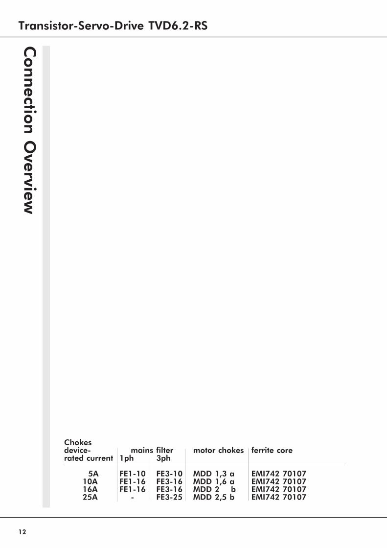
Chokesdevice- mains filter motor chokes ferrite corerated current 1ph 3ph
5A FE1-10 FE3-10 MDD 1,3 a EMI742 7010710A FE1-16 FE3-16 MDD 1,6 a EMI742 7010716A FE1-16 FE3-16 MDD 2 b EMI742 7010725A - FE3-25 MDD 2,5 b EMI742 70107
Con
nectio
nO
verview

TVD6.2-400-x-RS 13
Con
nect
ion
com
pact
devic
e:
on
lyle
ftd
iag
ram
with
ou
tin
tern
al
con
nec
tion
sC
on
nect
ion
mu
lti-
axes
com
bin
ation
:O
ne
or
more
axe
sw
ith
pow
ersu
pp
lyu
nit,
plu
son
eor
more
axe
sw
ith
ou
tow
np
ow
ersu
pp
lyu
nit
pow
ersu
pp
lyu
nit-
posi
tion
sfr
eech
oosa
ble
3 Electrical Installation
Con
nec
tion
Plan
s

Transistor-Servo-Drive TVD6.2-RS
14
The devices are according to EU-regulation 89/336/EWG, the standards EN 50081-2 and
prEN 50082-2 will be observed under the following conditions.
Device,transformer,motor chokes and mains filter fixed on a 500x500x2 mm mountingboard.Mounting board and motor frame connected to gnd with a 10mm² wire.Devices reference X1:13 connected to mounting board with a 2,5mm² wire.Device-PE-screw connected to mounting board with a 50mm long 4mm² line.Single-phase power supply:
mains filter Type : up to 16A = FE1-16linelength device - mains filter <100mm
Three-phase power supply:
mains filter Type : up to 16A = FE3-16up to 25A = FE3-25
linelength transformer - mains filter <500mmlinelength device - mains filter <100mm
Motor connection:
motor chokes Type : 10A = MDD1,6-1016A = MDDxx-2025A = MDDxx-30
motor line 1,5m long, 4core shielded. Shielding on device side fixed to mountingboard and on motor side flächig connected to PE.
Earth
ing
Plan
EMC
-Ad
vice

TVD6.2-400-x-RS 15
Caution:
The connection advice concerning the individual attachments of the con-
nections to the plug numbers or terminals are binding.
All further advices to this are not binding.The input and output lines can be altered or completed in consideration ofthe electrical regulations.
Notice:
- connection advice and operation advice
- local technical regulations
- EU-machine regulation 89/392/EWG
Input filter:
see CE-advice (page 14)short line length between input filter and deviceor shielded line
FI-switch
- design to DIN VDE 0664- tripping current > 200mA- only combined with other protective measure
Connection to 400 V~ mains
Alternating voltage connection 1x400V~ 50/60Hz
compact device up to 10A.multi axis combination up to 20A
Three-phase current-connection 3x400V~ 50/60Hz
with >10A (multi axes rack >20A) necessary
dimensioning 5/10A 16A 25A max. 30A
wire cross section mm² 0.75 1.5 2.5 2.5fusingblow-out fuse AF 10 16 25 30automatic circuitbreaker A 10 16 25 25electronical starting current limitation >>> max. current 7A~
3 Electrical Installation
Main
sC
on
nec
tion

Transistor-Servo-Drive TVD6.2-RS
16
Connection at 400 V mains
AC or three-phase voltage supplyautotransformer or isolation transformerone transformer for several devices
Notice:
-set safety contacts on transformer inrush current.-slow fuses in front of the transformer-fuse value corresponding to the transformer rated current-quick fuses after the transformer-fuse value for each power supply unit max. 30AF
Transformer capacity:
primary voltage 500V~secondary voltage 400V~
Autotransformer
transformer rated power [VA]= 0,2 x 400 x IM x GLF x nFIsolation transformer
transformer rated power [VA]= 1,25 x 430 x IM x GLF x nFIM = total power of the motorsGLF = coincidence factornF = speed ratio factor
GLF = nF =
1 with one motor effective speed0,5 ... 0,7 with 2 motors maximum speed0,4 ... 0,6 with >2 motors
AC three phase current
Main
sC
on
nectio
n

TVD6.2-400-x-RS 17
Motor connections
wire number PE M1 M2 M3connection X3:6 X3:7 X3:8 X3:9X3:6 is internally connected with the devices PE-bolt.
motor line at 5A 10A 16A 25A thermo brakecross section 0,75 1,5 1,5 2,5 0,75 0,75kind of cable 3x motor line shielded + PE
+ (if required: 2x thermo + 2x brake)
Shielding with earth clampconnected directly with the entryof the switch cabinet and the
motor earth manifold if thereare long lines .Ferrit core
- against HF-failureMotor chokes
- against HF-failure- against high discharge current- for high efficiency of the motor- for the duration of the motors life
External ballast resistor
dimensioning :average of the brake power per axis
1 x Jg x n² Jg² x a x nPballast [W] = x f
2 MM
Jg = motor- and effective load torque [kgm²]nmax = maximum speed [s ¹]MM = maximum motor torque [Nm]a = deceleration [s ²]f = repeating frequency of the braking[s ¹]
To change on back panel power supply unit:
- remove jump wire connection D- mount cable 1(external ballast resistor)
external ballast resistor >>> smallest resistance value 40W
internal ballast resistor 42W/ 50W, at 3%ED = 1,5 kW
3 Electrical Installation
Moto
rC
on
nec
tion

Transistor-Servo-Drive TVD6.2-RS
18
The connecting advices are for general information and
without obligation.
Notice:
- Connecting- and operating instructions
- Local regulations
- EU-machine regulation 89/392/EWG
Clamp terminal pin numbers
X1: 1 to X1:16 and X2 : 17 to X2 : 32
Signal lines
shielded and seperated from power linesnominal value lines paired twisted and shielded
Logical connections
Relay with golden pins or reed relay. Maximum currency on contact 6mA.
Internal logical voltage15V=
- Potential connection- With relay control- Jumper J1 and J3 pluggedExternal logical voltage
- Galvanic isolation- With SPS or CNC- UEXT +15 up to 30V= on clamp X2:27- GNDE on clamp X1:11- jumper J1 and J3 unplugged
- residual ripple of the logical voltage <20%
Default setup: jumper J1 and J3 plugged.Inputs and outputs with optocoupler.
Con
trol
Con
nectio
ns
Input Output
Output
TVD6.2-400-x-RS 19
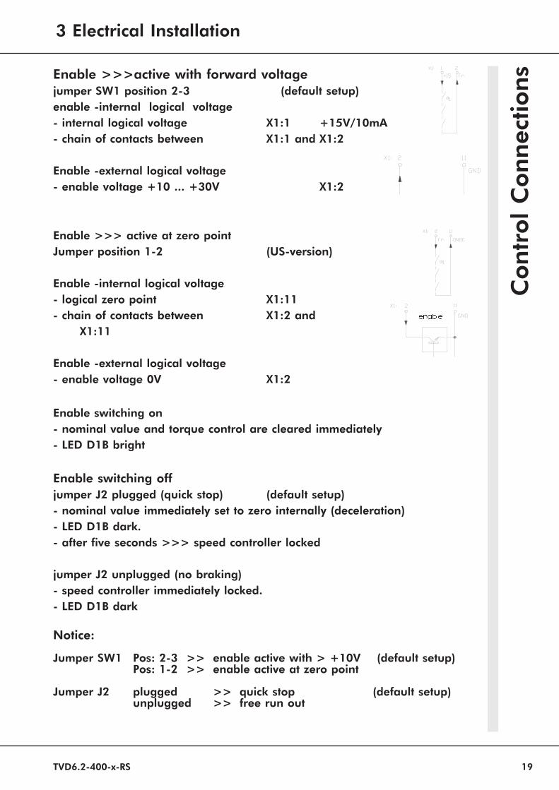
Enable >>>active with forward voltagejumper SW1 position 2-3 (default setup)
enable -internal logical voltage
- internal logical voltage X1:1 +15V/10mA- chain of contacts between X1:1 and X1:2
Enable -external logical voltage
- enable voltage +10 ... +30V X1:2
Enable >>> active at zero point
Jumper position 1-2 (US-version)
Enable -internal logical voltage
- logical zero point X1:11- chain of contacts between X1:2 and
X1:11
Enable -external logical voltage
- enable voltage 0V X1:2
Enable switching on
- nominal value and torque control are cleared immediately- LED D1B bright
Enable switching off
jumper J2 plugged (quick stop) (default setup)- nominal value immediately set to zero internally (deceleration)- LED D1B dark.- after five seconds >>> speed controller locked
jumper J2 unplugged (no braking)- speed controller immediately locked.- LED D1B dark
Notice:
Jumper SW1 Pos: 2-3 >> enable active with > +10V (default setup)Pos: 1-2 >> enable active at zero point
Jumper J2 plugged >> quick stop (default setup)unplugged >> free run out
Con
trol
Con
nec
tion
s
enable
3 Electrical Installation

Transistor-Servo-Drive TVD6.2-RS
20
Limit switch
Limit switch inputs
enable for- positive nominal value LED 1D >>>contact between X2:27 andX1:16- negative nominal value LED 1H >>>con-tact between X2:27 and X2:32Limit switch direction
contact functionlocked enable>LED bright
open
direction lock
> limit switch is occupied >>> contact open- drive decelerates> change of the nominal value- drive moves from limit switch- limit switch cleared >>> contact closedCaution:
Without limit switch >>> connection between X2:27, X2:32 and X1:16
Integral switching offFunction - relay contact
contact speed controlleropen P-I regulationlocked P- regulation
Function - external logical voltage
voltage X2:31 speed controller< 2V P-I regulation> 10V P- regulation
Caution:
Notice optimization advices.
Mains failure-braking
braking function- nominal value is set immediately to zero
Generatoric rear feed into the intermediate circuit.
endswitch+
Con
trol
Con
nectio
ns
endswitch-

TVD6.2-400-x-RS 21
Speed-nominal value
voltage source for nominal values ±10V, 10mA
+10V X1:3
-10V X1:5
GND X1:8
with internal voltage source >>> Jumper S11, S12 plugged
Nominal value inputs
- maximum nominal value voltage ±10V=
- input resistance 50 kW
- relay contacts: gold or reed contacts
Nominal value lines paired twisted and shielded. Shield connection one sided
Connection
connection jumper function measuring point
nominal X1:4 (signal) directly X4:1
value 1 X1:8 (GND) X4:10
nominal X2:17(signal) SW2 1-2 directly X4:2
value 2 SW2 2-3 ramp X4:2
X2:28 (GND) X4:10
Jumper positions
function jumper position default setup
nominal value1
differential input S12 unplugged ***
with internal voltage source S12 plugged
nominal value 2
differential input S11 unplugged ***
with internal voltage source S11 plugged
with ramp (integrator) SW2 Pos. 2-3 ***
without ramp SW3 Pos. 1-2
without nominal value 2 SW2 unplugged
Resistors for nominal value current 0 ... ±20mA
nominal value 1 R121 500W
nominal value 2 R4 500W
internal supply CNC/SPS nominal value current
3 Electrical Installation
Con
trol
Con
nec
tion
s

Transistor-Servo-Drive TVD6.2-RS
22
External current limitation
voltage source for external current limit+10V/10mA X1:3
Control range:
0 ... + 5V >>> 0 up to 100% rated current0 ... +10V >>> 0 up to 200% rated current
internal overcurrent control >>> max. 5 sec.
Inputs
maximum input voltage +10V
input resistance 10 kW
internal attenuatiuon with trimer Imax1, Imax2
relay contacts: gold or reed contacts
Connection
current limit conection jumper measuring point
positve X1:9 (signal) S19 unplugged X4:3X1:7 (GND) X4:10
negative X1:10 (signal) S20 unplugged X4:3X1:7 (GND) X4:10
internal supply CNC/SPS nominal value current
Caution:
with internal current limit adjustment >>> jumper S19, S20 plugged.
Con
trol
Con
nectio
ns

TVD6.2-400-x-RS 23
Actual Value-Connection
Connector X7
- D-connector 15 pins- Case metallized plastic- Shielding on caseLine: resolver line
3x (2x 0,25 drilled and shielded) + 2x 0,5 shielded
Pin assignment X7
Incremental encoder- output
Connector X8
- D-connector 9 pins- Case metallized plastic- Shielding on caseLine: until10m 6x 0,14 + 2x 0,5 shielded
> 10m 6x 0,25 + 2x 0,5 shielded
Pin assignment X8
Caution: Notice motorspecific connection sheets. Appendix A.
Function colour Pin-No
reference A (R1) white X7: 13reference B (R2) brown X7: 4
sine A (S1) yellow X7: 2sine B (S2) green X7: 15cosine A (S3) pink X7: 14cosine B (S4) grey X7: 3
temperature sensor X7: 6temperature sensor X7: 12
with motors withouttemperature sensor >>>>>> bridge between pin 6 and 12
Function Colour Pin-No.
channel A red 2channel /A black 9channel B brown 3channel /B green 8null pulse N grey 7null pulse /N pink 4
supply +5V, 150mA violet 0,5 1supply GND blue 0,5 5connect allways supply!
3 Electrical Installation
Con
trol
Con
nec
tion
s

Transistor-Servo-Drive TVD6.2-RS
24
Ready for operation- BTB signal
Relay RL2
signal contact X2:21 - X2:22contact values max. 48V, 0.5A
The ready for operation signal (BTB) shows the control (CNC/SPS)that the drive is in working order.Connect BTB-signals of several axes in series.
delay after switching on the mains >>> max. 1sec.
Indication
ready for operation LED D1A bright contact closederror LED D1A dark contact open
BTB turns off with
individual error BTB-LED D1A single signal- LED
actual value error dark LED D2H brightovertemperature dark LED D2G brightshort, line-to-earth fault dark LED D2F brightvoltage error dark LED D2B brightbuffer circuit error dark LED D2A bright
Caution:
In any case use BTB-contact with CNC/SPS -Control !
Analogue measuring outputs
function motor currency speed
connection X2:20 - X2:24 X1:6 - X1:7measuring 2,5V= current limit tachometer vol-tagevalue 5,0V= peak current before divider
unipolar positiv bipolarOutput-
Resistance 1 kW 4,7 kW
Con
trol
Con
nectio
ns
TVD6.2-400-x-RS 25
Signal output
logical outputs with opto-coupler- wire break secure in case of error output is locked- output voltage 10 ... 30V=- output voltage 5mA- output resistance 1kW
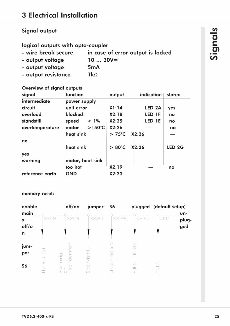
Overview of signal outputs
signal function output indication storedintermediate power supplycircuit unit error X1:14 LED 2A yesoverload blocked X2:18 LED 1F nostandstill speed < 1% X2:25 LED 1E noovertemperature motor >150°C X2:26 — no
heat sink > 75°C X2:26 —no
heat sink > 80°C X2:26 LED 2Gyeswarning motor, heat sink
too hot X2:19 — noreference earth GND X2:23
memory reset:
enable off/on jumper S6 plugged (default setup)mainsoff/on
jum-per
S6
un-plug-ged
Sig
nals
3 Electrical Installation

Transistor-Servo-Drive TVD6.2-RS
26
Control Connection X1,X2
Function Terminal No. Intern. Connec-
tor
No.+ 15 Volt (for enable) X1: 1 X11: 32cenable input (+10 ... +30 Volt) X1: 2 X11: 30c+ 10 Volt (for nominal value) X1: 3 X11: 28cnominal value 1-input (signal) X1: 4 X11: 26c- 10 V (for nominal value) X1: 5 X11: 24c
DC-tachometer -input (signal) X1: 6 X11: 22cDC-tachometer-input (AGND) X1: 7 X11: 20cnominal value 1-input (AGND) X1: 8 X11: 18cexternal current limit I1 X1: 9 X11: 16cexternal current limit I2 X1: 10 X11: 14cexternal GNDE X1: 11 X11: 12c-15V (external electronics) X1: 12 X11: 10cdevice ground GND X1: 13 X11: 8cintermediate circuit error X1: 14 X11: 6camplification 1:1 X1: 15 X11: 4climit switch (-) X1: 16 X11: 2cnominal value 2-input (signal) X2: 17 X11: 32aoverload signal X2: 18 X11: 30a
overload tacho error ortemperature error X2: 19 X11: 28acurrent (I-actual) X2: 20 X11: 26aready/operational BTB X2: 21 X11: 24aready/operational BTB X2: 22 X11: 22adevice ground GND (mass) X2: 23 X11: 20aanalogue device ground (AGND) X2: 24 X11: 18astandstill signal X2: 25 X11: 16aover-temperature X2: 26 X11: 14aexternal voltage UEXT X2: 27 X11: 12a
nominal value 2 (AGND) input X2: 28 X11: 10anominal current value X2: 29 X11: 8a+15V (external electronics) X2: 30 X11: 6aintegral component interlock X2: 31 X11: 4alimit switch (+) X2: 32 X11: 2a
Con
necto
rPla
n

TVD6.2-400-x-RS 27
Con
nec
tor
Plan
Control Connector X4 (front panel)Function Pin-No.
1st nominal value according tothe differential amplifier X4: 1
2nd nominal value according tothe diff. amplifier or integrator X4: 2
I-nominal value X4: 3+10 V X4: 4-10 V X4: 5I-actual value X4: 6n-actual value (normalised) X4: 7enable X4: 8device ground GND X4: 9, 10
Power connection X3
Function Terminal No. Intern.Connector
No.
intermediate circuit ex. load resistor X3:1 X31: 18,2 0 abcintermediate circuit + X3:2 X31: 14, 16 abc
power L1 400V~ X3:3 X31: 10, 12 abcpower L2 400V~ X3:4 X31: 6, 8 abcpower L3 400V~ X3:5 X31: 2, 4 abcearth PE X3:6motor 1 X3:7 X31: 22, 24 abemotor 2 X3:8 X31: 26, 28 abemotor 3 X3:9 X31: 30, 32 abe
3 Electrical Installation

Transistor-Servo-Drive TVD6.2-RS
28
Con
necto
rPla
n
Encoder Connector to Motor X7
Function Colour D-Connector-No.
reference A (R1) white X7: 13reference B (R2) brown X7: 4
sine A (S1) yellow X7: 2sine B (S2) green X7: 15cosine A (S3) pink X7: 14cosine B (S4) grey X7: 3
temperature sensor X7: 6temperature sensor X7: 12
Kabel: 3x (2x 0,25 twisted and shielded) + 2x 0,25 (Temp)Schield on connector case.
Encoder Connector to CNC\SPS X8
Function colour D-Connector-No.
channel A red X8: 2channel /A black X8: 9channel B brown X8: 3channel /B green X8: 8zero pulse N grey X8: 7zero pulse /N pink X8: 4+5V/50mA external violet 0,5 X8: 1GND internal/external blue 0,5
X8: 5Notice motorspecific connection sheets. Appendix A.

TVD6.2-400-x-RS 29
Res
olv
er
4 Device Overview

Transistor-Servo-Drive TVD6.2-RS
30
Com
pon
etPo
sition

TVD6.2-400-x-RS 31
Blo
ckD
iag
ram
4 Device Overview

Transistor-Servo-Drive TVD6.2-RS
32
Indicator LEDs 2xactual value errortemperature errorshort detectionrotor position 3rotor position 2rotor position 1voltage errorintermediate circuit errorAdjustment potentiometer- Imax current limit+Imax current limit
Control Connector X41 1.nominal value after the
diff. amplifier2 2.nominal value after the
integrator3 nominal current value4 + 10V5 - 10V6 current - actual value7 speed - actual value8 enable9 n.c.10 device ground GNDIndicator LEDs 1xend limit switch +end limit switch -overload - blockedstandstillcurrent direction -current direction +enableenable ready/operational BTBAdjustment PotentiometerID continous current limitXp amplificationINT Integrator-timenmax speedOffset zero point
Fron
tpan
el
TVD6.2-400-x-RS 33
Ad
just
men
tFu
nct
ion
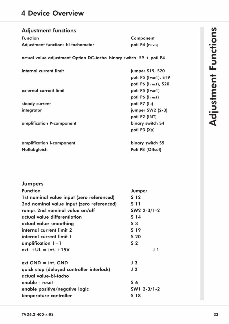
sAdjustment functions
Function Component
Adjustment functions bl tachometer poti P4 (nmax)
actual value adjustment Option DC-tacho binary switch S9 + poti P4
internal current limit jumper S19, S20
poti P5 (Imax1), S19
poti P6 (Imax2), S20
external current limit poti P5 (Imax1)
poti P6 (Imax2)steady current poti P7 (ID)
integrator jumper SW2 (2-3)
poti P2 (INT)
amplification P-component binary switch S4
poti P3 (Xp)
amplification I-component binary switch S5
Nullabgleich Poti P8 (Offset)
Jumpers
Function Jumper1st nominal value input (zero referenced) S 122nd nominal value input (zero referenced) S 11ramps 2nd nominal value on/off SW2 2-3/1-2actual value differentiation S 14actual value smoothing S 3internal current limit 2 S 19internal current limit 1 S 20amplification 1=1 S 2ext. +UL = int. +15V J 1
ext GND = int. GND J 3quick stop (delayed controller interlock) J 2actual value-bl-tachoenable - reset S 6enable positive/negative logic SW1 2-3/1-2temperature controller S 18
4 Device Overview

Transistor-Servo-Drive TVD6.2-RS
34
LED- indicators
Function LED-No.
Control electronics LED D1x
limit switch + LED Hlimit switch - LED Gblocked LED Fstandstill LED Espeed controller output - LED Dspeed controller output + LED Cenable nominal value LED Bready/operational (BTB) LED A
Power section LED D2x
actual value error (stored) LED Htemperature (optional)LED Gshort detection (stored) LED Frotor position R3 LED Erotor position R2 LED Drotor position R1 LED Cvoltage error (stored) LED Bintermediate circuiterror (not stored). LED A
Sign
als

TVD6.2-400-x-RS 35
Adjustment Advice
adjustments
- only by qualified personnel
- adhered to safety regulations
- notice adjusting sequence
Presettings
actual value >>> jumper, networksnominal value inputs, >>> jumper, differential inputlogical inputs/outputs >>> jumper, int/ext. supplyP-I parameter switch >>> jumper, switch
Optimization
actual value-adjustment nmax adjustment
current regulator adjustment by the factory (P- or PI-Controller)current limits Imax, ID-adjustmenttorque controller P-I-switch, Xp-adjustmentslope limitation INT-adjustment (only nominal value 2)zero point offset-adjustmentposition controller in CNC\SPS
Caution:
control systems have to be optimized from inside to outside.sequence: current controller>> torque controller>>position controller(CNC\SPS)
Measuring values
control connector X4measuring value max.value measuring
point1st nominal value after input amplifier ±10V X4:12nd nominal value after input amplifier ±10V X4:2nominal value current (speed controller) ±10V X4:3actual value current unipolar + 5V X4:6torque actual value after divider ± 5V X4:7
Ad
just
men
tA
dvi
ce
5 Adjustment

Transistor-Servo-Drive TVD6.2-RS
36
Function 1st nominal value 2nd nominal va-
lue
input amplifier constant 1 1input voltage max. ±10V= ±10V=differential input jumper S12 unplugged S11 unpluggedinput according to GND jumper S12 plugged S11 pluggedinput signal X1:4 X2:17input GND X1:8 X2:28measuring point control pin X4:1 X4:2measuring value max. ±10V= ±10V=
integrator function does not exist jumper SW2
Input in relation to GND Differential input
with nominal value potentiometer with nominal value of SPS/CNCwith internal supply voltage foreign external voltagejumper S11, S12 plugged jumper S11, S12 opennotice GND connection signal- and GND-connection
exchangeabledefault setup
Both nomimal values connected:
- 1st and 2nd nominal value are added internally- notice signs- sum of nominal values not over ±10VOnly with 2nd nominal value
-acceleration and deceleration-ramp linear integrator2nd nominal value jumper Poti rangewithout integrator SW2 pos. 1-2 —- ——with integrator SW2 pos. 2-3 INT(P2)
0,1 up to 4,5sec.without 2nd nom.value SW2 unplugged —-
Nominal value current
nominal value from external supply 0 to ±20mAinternal compliance resistors 0 to max. ±10V
1st nominal value resistor R1212nd nominal value resistor R4
Resistance value [W]= nominal value voltage / nominal value current
(max. 500W )
Nom
inal
Valu
e

TVD6.2-400-x-RS 37
Actual Value-Speed
Caution:
Please pay attention to the motor specific connection sheets.
see Appendix A
coarse adjustment
see page 29
Fine adjustment
with potentiometer nmax (P4)with nom. value from potentiometer:
with 1V Sollwert adjust to 10% maximum speedwith 10V Sollwert fine adjust to 100% .
with nom. value from CNC\SPS:with 0,8V Sollwert adjust to 10% maximum speed
Direction of rotation (looking at motor backside-DIN)change nominal value polarity at the differtial input
.
Act
ual
Valu
e
5 Adjustment

Transistor-Servo-Drive TVD6.2-RS
38
Current Limitation
peek current range 0 up to 200% rated current Poti P5/P6reset time max. 5 sec.
steady current range 5 up to 100% rated current Poti P7
Internal reducing current limits
current limit function limitoverload time steady currentheat sink temperature 50% rated currentmotor temperature 50% rated current
The lowest current limit is active!
Peek current
internal current limit (default setup)adjustment Jumper PotiImax1 S19 plugged Imax1 (P5)Imax2 S20 plugged Imax2 (P6)
external current limitadjustment input Jumper PotiImax1 X1:9 0 .. +10VS19 unplugged Imax1 (P5)Imax2 X1:10 0 .. +10VS20 unplugged Imax2 (P6)
The external current limit can be internally reducedwith the Imax-potentiometer.
Steady current
motor protection adjustment for both torque directions tomotor rated current potentiometer ID (P6)
Measure adjusted values:
- motor not connected- predetermine nominal value and enable >> turn on/off- measuring value at connector X4:3 (5V=rated current)
nom.value measuring value Imax (2 sec.) measuring value ID+5V 0 bis max.10V 0,25 bis max. 5V- 5V 0 bis max.10V 0,25 bis max. 5V
Current-actual value
measuring value at connector X4:6 >>> Imax = 0 up to +5V,ID = 0,12 up to +2,5V
Caution:
for exact torque regulation:-changing of adjustment from P-toPI-regulation in the current
regulator by the manufacturer
Cu
rrent

TVD6.2-400-x-RS 39
Speed control switching- two 16 pole binary switches S4, S5- amplification trimmer P3 (Xp)- D-component with jumper S14- in case of exchanging the devices>>> take over adjustment values.
Default setup
- binary switch S4 und S5 on position 4- amplification trimmer Xp on 50%- no D-component, jumper S14 open- optimal for most drives.
Caution:
with the input INTAB (X2:31) the I-component can be switched off.
Adjustment P-component with the binary switchS4switch S4position 0 1 2 3 4 5 6 7R-value 1000 450 280 209 180 148 123107 kW
position 8 9 A B C D E FR-value 90 82 73 67 64 59 55 52 kW
adjustment I-component with the binary switch S5switch S5position 0 1 2 3 4 5 6 7C-value 0,01 0,02 0,03 0,04 0,08 0,09 0,1 0,11 mF
position 8 9 A B C D E FC-value 0,11 0,12 0,13 0,14 0,18 0,19 0,2 0,21 mF
Spee
d
5 Adjustment

Transistor-Servo-Drive TVD6.2-RS
40
Proportional amplificationfunction binary switch S4 function potentiometer XP
proportional amplification = Xp x FxpAdjustment with osciloscope
Adjust Measuring value
- nominal value jump ± 0,5V nominal value X4:1
- input INTAB X2:31 activated reply of the controller
nominal value current X4:3
Effect D-component
- nominal value -differentiation
- jumper S14 plugged
Caution:
In case of position control (CNC/SPS)
do not use D-component
Speed
con
troller

TVD6.2-400-x-RS 41
Adjustment without measuring instrumentsconnect the motor,
nominal value = 0Xp = 50%switch S4 = position 4switch S5 = position 4
enable the device,turn potentiometer Xp clockwise until the drive swings.
if there is no oscillation-turn switch S4 back to a lower value-set to swinging with potentiometer Xp-turn the potentiometer Xp anti-clockwise until the swinging fades out-turn potentiometer Xp another two positions anti-clockwise.
Setup switch S5 so, that the drive runs smoothly after about twooscillations when there was a nominal value jump off 50%.
Responce of the drive:
amplification too low amplification too highlong wave oscillation 1 ... 0,1Hz short wave oszillation 30 ... 200Hzlong ballistic factors vibrates >in case of acceleration,overshoots target position vibrates >in case of deceleration
and in position
Caution:
operation with CNC\SPS - control-ad maximum speed >>> speed nominal value from 8 up to 9V
Spee
dC
on
trolle
r
5 Adjustment
Transistor-Servo-Drive TVD6.2-RS
42
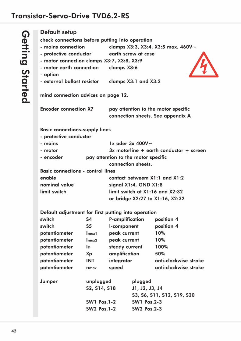
Default setup
check connections before putting into operation
- mains connection clamps X3:3, X3:4, X3:5 max. 460V~
- protective conductor earth screw at case- motor connection clamps X3:7, X3:8, X3:9- motor earth connection clamps X3:6- option- external ballast resistor clamps X3:1 and X3:2
mind connection advices on page 12.
Encoder connection X7 pay attention to the motor specificconnection sheets. See appendix A
Basic connections-supply lines
- protective conductor- mains 1x oder 3x 400V~- motor 3x motorline + earth conductor + screen- encoder pay attention to the motor specific
connection sheets.Basic connections - control lines
enable contact betweem X1:1 and X1:2nominal value signal X1:4, GND X1:8limit switch limit switch at X1:16 and X2:32
or bridge X2:27 to X1:16, X2:32
Default adjustment for first putting into operation
switch S4 P-amplification position 4switch S5 I-component position 4potentiometer Imax1 peak current 10%potentiometer Imax2 peak current 10%potentiometer ID steady current 100%potentiometer Xp amplification 50%potentiometer INT integrator anti-clockwise strokepotentiometer nmax speed anti-clockwise stroke
Jumper unplugged pluggedS2, S14, S18 J1, J2, J3, J4
S3, S6, S11, S12, S19, S20SW1 Pos.1-2 SW1 Pos.2-3SW2 Pos.1-2 SW2 Pos.2-3
Gettin
gSta
rted

TVD6.2-400-x-RS 43
Get
tin
gSt
art
edturn on mains
LED D1A brightLED D1E bright
check mains connectionturn off mains
check power supply unit fuse
turn off mainscheck limit switchesconnect limit switchesor thread bridges
LED D1H brightLED D1G bright
enable drive
turn off mainscheck enable voltage andchain of enable contactsLED D1B bright
increase nom.value to 10%
motor turnswith about 10% ofmaximum speed
motor speeds up>>motor stands still >>
turn off mainscheck motor and encoder lines
motor run smoothnot jerky
amplification too high Xp >>turn anticlockwiseturn off mains
check motor and encoder lines
adjust speed withpoti nmax to 10%
adjust nom. dcvalue value to 0V
drive stands still adjust speed with poti �Offset�to standstill
increase nom.value to 50%turn poti X clockwise until the drive
oszillates, then turn anti-clockwise untilthe drive runs smooth
adjust current limits with poti Imax1 andImax2 to the peek current
and with poti ID to the steady currentacording to the motor data
Getting started finishedturn off mains
optimize drive and record the adjustmentdates in the protocol
yes
yes
yes
yes
yes
yes
yes
yes
yes
no
no
no
no
no
no
6 Getting Started
Transistor-Servo-Drive TVD6.2-RS
44
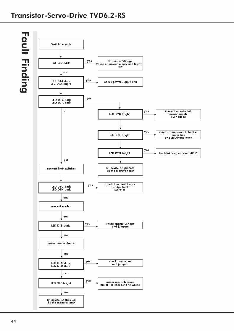
All LED dark No mains V0ltagefuse on power supply unit blown
out
LED D1A darkLED D2A bright Check power supply unit
LED D1A darkLED D2A dark
LED D2B bright
LED D2F bright
LED D2G bright
internal or externalpower supplyoverloaded
short or line-to-earth fault inmotor line
or outputstage error
heatsink-temperature >80°C
connect limit switches
LED D1G darkLED D1H dark
check limit switches orbridge limitswitches
connect enable
check enable voltageand jumpersLED D1B dark
preset nom.v alue ±
LED D1C darkLED D1D dark
motor mech. blockedmotor- or encoder line wrongLED D1F bright
check nom.valueand jumper
let device be checkedby the manufactorer
Switch on mais
Fau
ltFin
din
g
let device be checkedby the manufactorer
yes
yes
yes
yes
yes
yes
yes
yes
yes
yes
yes
yes
yes
no
no
no
no
no
no
TVD6.2-400-x-RS 45
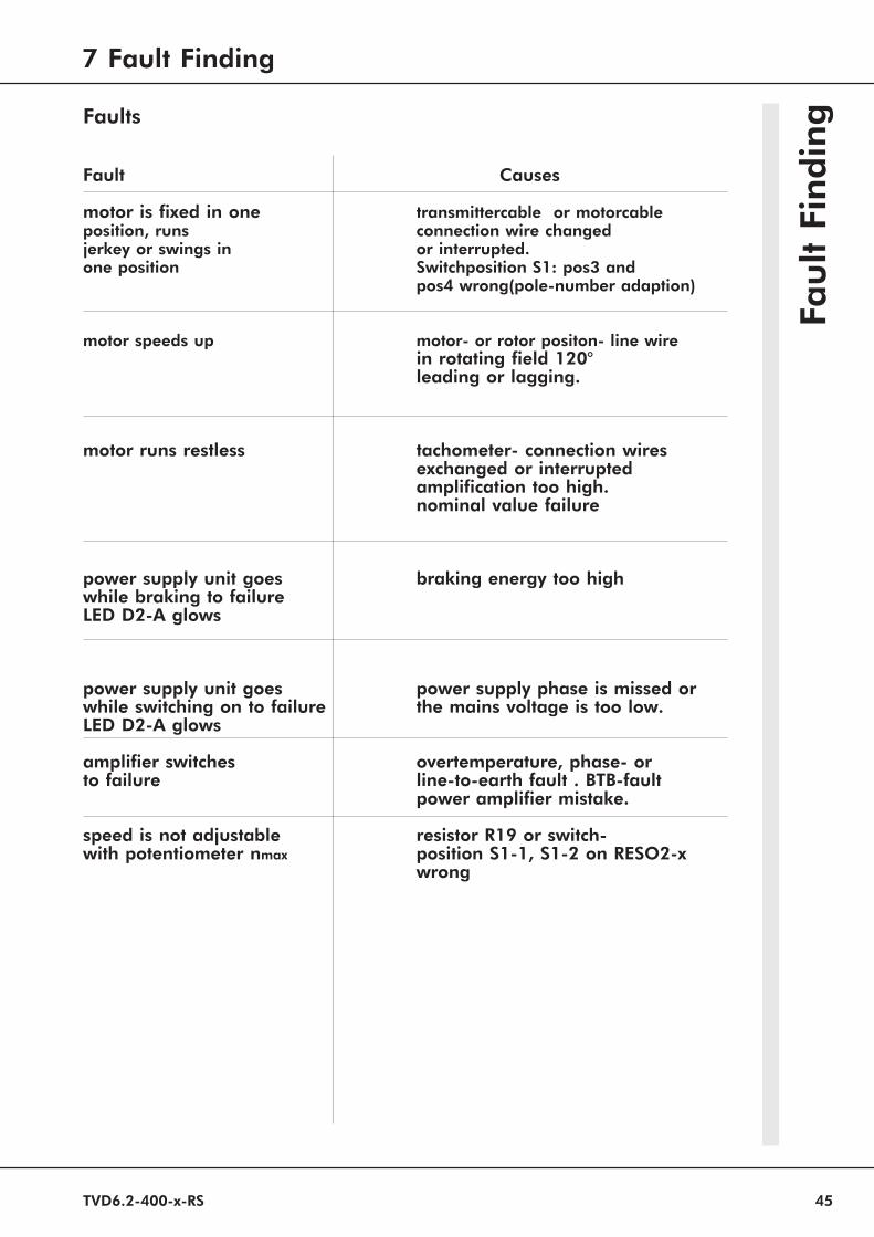
Faults
Fault Causes
motor is fixed in one transmittercable or motorcableposition, runs connection wire changedjerkey or swings in or interrupted.one position Switchposition S1: pos3 and
pos4 wrong(pole-number adaption)
motor speeds up motor- or rotor positon- line wirein rotating field 120°leading or lagging.
motor runs restless tachometer- connection wiresexchanged or interruptedamplification too high.nominal value failure
power supply unit goes braking energy too highwhile braking to failureLED D2-A glows
power supply unit goes power supply phase is missed orwhile switching on to failure the mains voltage is too low.LED D2-A glows
amplifier switches overtemperature, phase- orto failure line-to-earth fault . BTB-fault
power amplifier mistake.
speed is not adjustable resistor R19 or switch-with potentiometer nmax position S1-1, S1-2 on RESO2-x
wrong
Fau
ltFi
nd
ing
7 Fault Finding

Transistor-Servo-Drive TVD6.2-RS
46
Con
necto
rX4

TVD6.2-400-x-RS 47
Enco
der
Sig
nals
Motor voltage
Resolver Signals
Motor current
7 Fault Finding
Transistor-Servo-Drive TVD6.2-RS
48
UNITEK products have a warranty against defects in material andworkmanship for a period of one year from the date of shipment. All valu-es from the pre- and final quality control checks are archivied with thedevices’ serial numbers. UNITEK does not guarantee the suitability of thedevice for any specific application.During the warranty period, UNITEK will, at its option, either repair or re-place products that prove to be defective, this includes guaranteed functio-nal attributes. UNITEK specifically disclaims the implied warranties ormerchantability and fitness for a particular purpose. For warranty serviceor repair, this product must be returned to a service facility designated byUNITEK.For products returned to UNITEK for warranty service, the Buyer shall pre-pay shipping charges to UNITEK and UNITEK shall pay shipping charges toreturn the product to the Buyer.However, the Buyer shall pay all shipping charges, duties, and taxes forproducts returned to UNITEK from another country.
The foregoing warranty shall not apply to defects resulting from:* improper or inadequate repairs effected by the Buyer or
a third party,* non-observance of the manual which is included in the all
consignments,* non-observance of the electrical standards and regulations* improper maintenance* acts of nature
All further claims on transformation, diminution and replacement of anykind of damage, especially damage, which does not affect the UNITEK de-vice, cannot be considered. Follow-on damage within the machine or sys-tem, which may arise due to malfunction or defect in the devicecannot be claimed. This limitation does not affect the product liability lawsas applied in the place of manufacture (i. e. Germany).
UNITEK reserves the right to change any information included in thisMANUAL. All connection circuitry discribed is meant for generalinformation purposes and is not mandatory.The local legal regulations, and those of the Standards Authorities haveto be adhered to. UNITEK does not assume any liability, expressively orinherently, for the information contained in this MANUAL, for thefunctioning of the device or its suitability for any specific application.
All rights are reserved.Copying, modifying and translations lie outside UNITEK’s liability and thusare not prohibited. UNITEK’s products are not authorized for use as criti-cal components in the life support devices or systems without express writ-ten approval.The onus is on the reader to verifiy that the information here is current.
Gu
ara
ntee

TVD6.2-400-x-RS 49
Proto
col
Customer: . . . . . . . . . . . . . . . . . . . . . . . . .Maschine-No . . . . . . . . . ..
Device: . . . . . . . . . . . . . . . . . . . . . . . . . Series-No . . . . . . . .. . . . . . .
Anschlußspannung [ V=,V~]. . . . . . . . . . . .
Eingänge
Enable Contact ? voltage [V=]
Nom. value1 Type voltage [V=]
Nom.value 2 additional Type voltage [V=]
current nom.value Imax1 external voltage [V=]
current nom.value Imax2 external voltage [V=]
Adjustments speed controller
Act.value coarse adjustmentDC-Tacho S9 position
Switch positions
P-component S4 positionI-component S5 position
Potistellungen
Speed nmax P4 positionPeek current Imax1 P5 positionPeek current Imax2 P6 positionSteady current ID P7 positionIntegrator INT P2 positionAmplification Xp P3 positionOffset Offset P8 position
Jumper (plug-in bridges) soldjumperplugged Nr. . . . . . . . . . . . . . . .Unplug Nr. . . . . . . . . . . . . .
9 Protocol
Transistor-Servo-Drive TVD6.2-RS
50 UNITEK Industrie Elektronik GmbH Industriestr.1 D-71397 Leutenbach-Nellmersbach b.Stuttgart
Proto
col
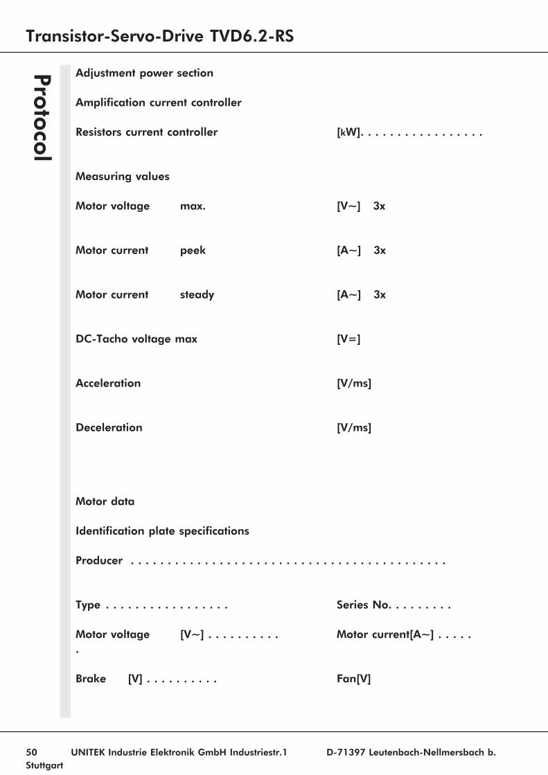
Adjustment power section
Amplification current controller
Resistors current controller [kW]. . . . . . . . . . . . . . . . .
Measuring values
Motor voltage max. [V~] 3x
Motor current peek [A~] 3x
Motor current steady [A~] 3x
DC-Tacho voltage max [V=]
Acceleration [V/ms]
Deceleration [V/ms]
Motor data
Identification plate specifications
Producer . . . . . . . . . . . . . . . . . . . . . . . . . . . . . . . . . . . . . . . . . . .
Type . . . . . . . . . . . . . . . . . Series No. . . . . . . . .
Motor voltage [V~] . . . . . . . . . . Motor current[A~] . . . . ..
Brake [V] . . . . . . . . . . Fan[V]
Related Documents