Toyota Corolla Manual de taller 2001-2004

Welcome message from author
This document is posted to help you gain knowledge. Please leave a comment to let me know what you think about it! Share it to your friends and learn new things together.
Transcript
Toyota Corolla
Manual de taller
2001-2004

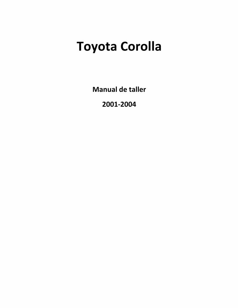
COMPONENTES
DEL ARBOL DE LEVAS
140OI–01
A64044
Engine Under Cover RH
Clip
Fan and Generator V Belt
Cylinder Head Cover No. 2
Clip
Engine Mounting Insulator RH
N·m (kgf·cm, ft·lbf) : Specified torque
52 (530, 38)
52 (530, 38)
7.0 (71, 62 in.⋅lbf)
–ENGINE MECHANICAL CAMSHAFT
14–93
1103
2004 COROLLA (RM1037U)
CAMSHAFT
COMPONENTS

A64043
Ventilation Hose No. 2
Clamp Bracket
Ventilation Hose
Ignition Coil Assy
Engine Wire
Clamp Bracket
Clamp Bracket
Gasket
Cylinder Head Cover
Sub–assy
Seal Washer
N·m (kgf·cm, ft·lbf) : Specified torque
9.0 (92, 80 in.⋅lbf)
9.0 (92, 80 in.⋅lbf)
9.0 (92, 80 in.⋅lbf)
9.0 (92, 80 in.⋅lbf)
11 (112, 8)
11 (112, 8)11 (112, 8)
11 (112, 8)
14–94–ENGINE MECHANICAL CAMSHAFT
2004 COROLLA (RM1037U)
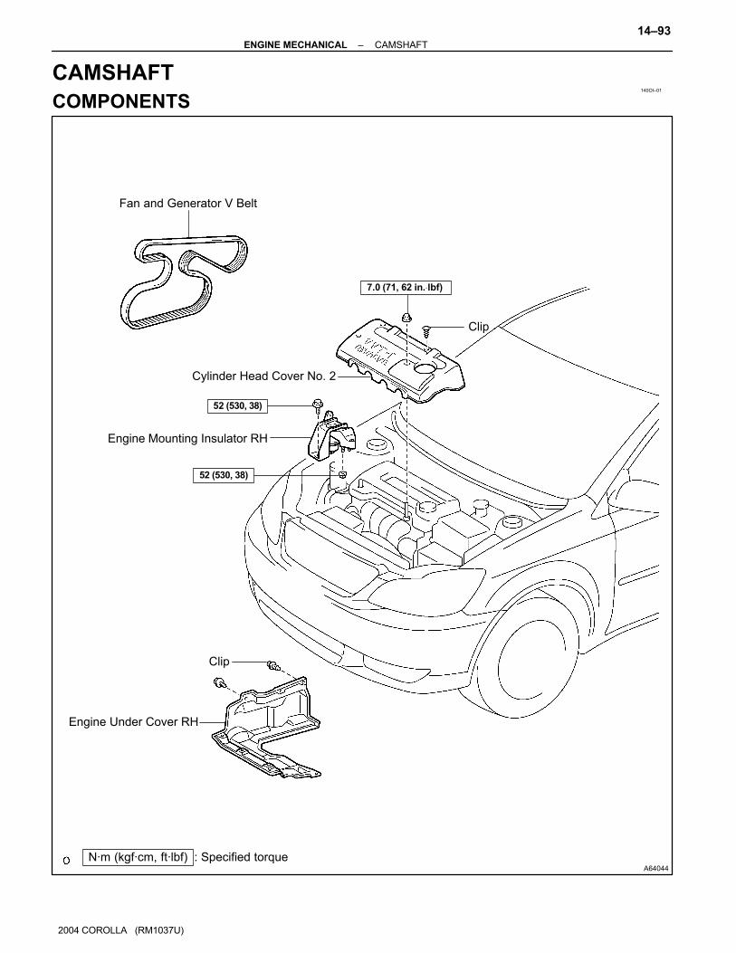
A64006
V–ribbed Belt
Tensioner Assy
Camshaft Bearing Cap No. 1
Camshaft Timing Gear
or Sprocket
Camshaft Timing Gear Assy
Chain Tensioner
Assy No. 1
Camshaft
Camshaft No. 2
Camshaft Bearing Cap No. 3
69 (704, 51)
29 (296, 21)
9.0 (92, 80 in.⋅lbf)
23 (235, 17)
54 (551, 40)
54 (551, 40)
13 (133, 10)
N·m (kgf·cm, ft·lbf) : Specified torque
Timing Chain Sub–assy
–ENGINE MECHANICAL CAMSHAFT
14–95
2004 COROLLA (RM1037U)
140OJ–01
A65077
A60622
A01045
A64005
14–96–ENGINE MECHANICAL CAMSHAFT
2004 COROLLA (RM1037U)
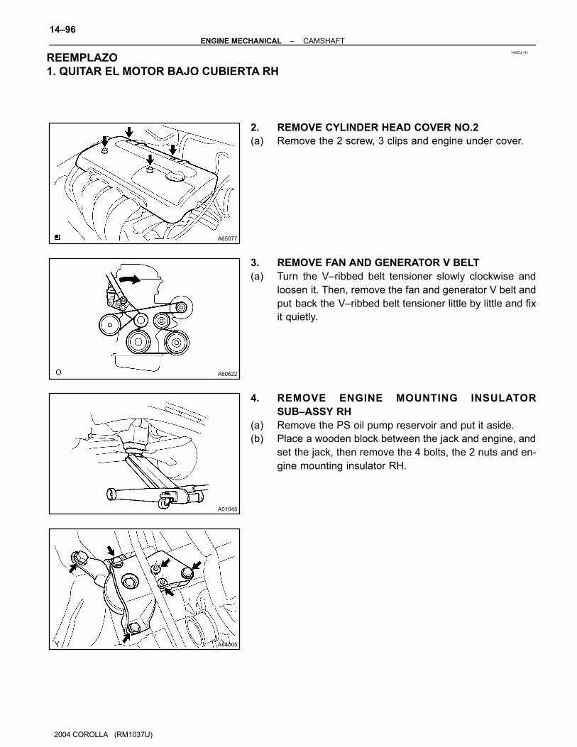
REPLACEMENT1. REMOVE ENGINE UNDER COVER RH
2. REMOVE CYLINDER HEAD COVER NO.2
(a) Remove the 2 screw, 3 clips and engine under cover.
3. REMOVE FAN AND GENERATOR V BELT
(a) Turn the V–ribbed belt tensioner slowly clockwise and
loosen it. Then, remove the fan and generator V belt and
put back the V–ribbed belt tensioner little by little and fix
it quietly.
4. REMOVE ENGINE MOUNTING INSULATOR
SUB–ASSY RH
(a) Remove the PS oil pump reservoir and put it aside.
(b) Place a wooden block between the jack and engine, and
set the jack, then remove the 4 bolts, the 2 nuts and en-
gine mounting insulator RH.
REEMPLAZO
1. QUITAR EL MOTOR BAJO CUBIERTA RH
A64021
A64022
A64023
A65078
A64058
–ENGINE MECHANICAL CAMSHAFT
14–97
1107
2004 COROLLA (RM1037U)
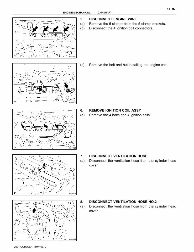
5. DISCONNECT ENGINE WIRE
(a) Remove the 5 clamps from the 5 clamp brackets.
(b) Disconnect the 4 ignition coil connectors.
(c) Remove the bolt and nut installing the engine wire.
6. REMOVE IGNITION COIL ASSY
(a) Remove the 4 bolts and 4 ignition coils.
7. DISCONNECT VENTILATION HOSE
(a) Disconnect the ventilation hose from the cylinder head
cover.
8. DISCONNECT VENTILATION HOSE NO.2
(a) Disconnect the ventilation hose from the cylinder head
cover.
A64856
A62185
Mark Mark
Mark
Timing Chain
Cover Surface
Groove
A11858
A62186
Paint Mark
14–98–ENGINE MECHANICAL CAMSHAFT
2004 COROLLA (RM1037U)
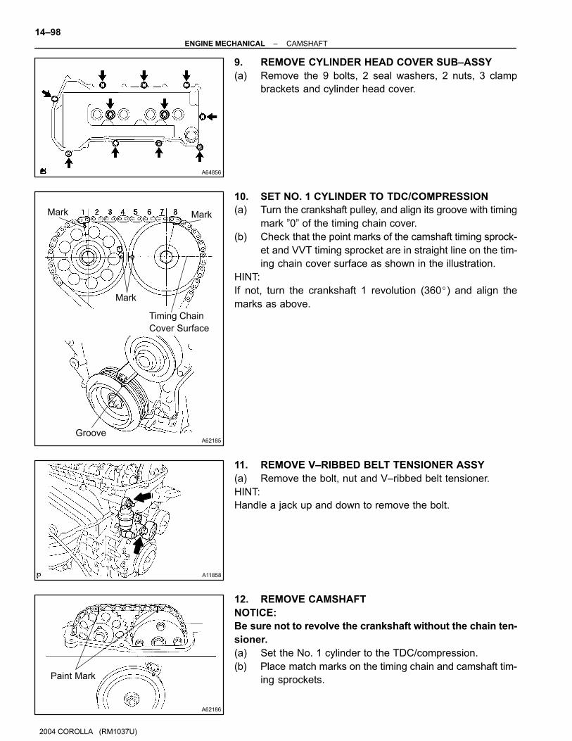
9. REMOVE CYLINDER HEAD COVER SUB–ASSY
(a) Remove the 9 bolts, 2 seal washers, 2 nuts, 3 clamp
brackets and cylinder head cover.
10. SET NO. 1 CYLINDER TO TDC/COMPRESSION
(a) Turn the crankshaft pulley, and align its groove with timing
mark ”0” of the timing chain cover.
(b) Check that the point marks of the camshaft timing sprock-
et and VVT timing sprocket are in straight line on the tim-
ing chain cover surface as shown in the illustration.
HINT:
If not, turn the crankshaft 1 revolution (360�) and align the
marks as above.
11. REMOVE V–RIBBED BELT TENSIONER ASSY
(a) Remove the bolt, nut and V–ribbed belt tensioner.
HINT:
Handle a jack up and down to remove the bolt.
12. REMOVE CAMSHAFT
NOTICE:
Be sure not to revolve the crankshaft without the chain ten-
sioner.
(a) Set the No. 1 cylinder to the TDC/compression.
(b) Place match marks on the timing chain and camshaft tim-
ing sprockets.

A62178
Push
A62187
Fix
Tighten
A62188
2 4 5 3 1
A32124
A621892 4 3 1
–ENGINE MECHANICAL CAMSHAFT
14–99
2004 COROLLA (RM1037U)
(c) Remove the 2 nuts and chain tensioner.
(d) Fix the camshaft with a wrench and so on, then loosen
the camshaft timing gear set bolt.
NOTICE:
Be careful not to damage the valve lifter.
(e) Loosen the camshaft bearing cap bolts on No. 2 camshaft
in the order as shown in the illustration in several
passes,and remove the caps.
(f) Remove the camshaft timing gear as shown in the illustra-
tion.
(g) Loosen the camshaft bearing cap bolts on camshaft in the
order as shown in the illustration in several passes,and
remove the caps.

A32125
A32556
A62190
Advance
Side Path
Retard Side
Path
Open
Close
RubberVinyl Tape
Open
Close
A62191
Advanced
Side Path
Retard
Side Path
14–100–ENGINE MECHANICAL CAMSHAFT
2004 COROLLA (RM1037U)
(h) Remove the camshaft with holding the timing chain.
(i) Tie the timing chain with a string as shown in the illustra-
tion.
NOTICE:
Be careful not to drop anything inside the timing chain cov-
er.
13. INSPECT CAMSHAFT TIMING GEAR ASSY
(a) Check the lock of camshaft timing gear.
(1) Grip the camshaft with a vice, and confirm the cam-
shaft timing gear is locked.
NOTICE:
Be careful not to damage the camshaft.
(b) Release lock pin.
(1) Cover 4 oil paths of cam journal with vinyl tape as
shown in the illustration.
HINT:
Two advance side paths are provided in the groove of the cam-
shaft. Plug one of the path with a rubber piece.
(2) Break through the tapes of the advance side path
and the retard side path on the opposite side of the
groove.
(3) Put air pressure into two broken paths (the advance
side path and the retard side path) with about 150
kPa {1.5 kgf⋅cm}.
CAUTION:
Cover the pathes with shop rag to avoid oil splashing.

A62192
Hold Pressure
Decompress
Advanced
Side Path
Retard
Side Path
A62190
Advance
Side Path
Retard Side
Path
Open
Close
RubberVinyl Tape
Open
Close
–ENGINE MECHANICAL CAMSHAFT
14–101
2004 COROLLA (RM1037U)
(4) Confirm if the camshaft timing gear assembly re-
volves in the timing advance direction when weak-
ening the air pressure of the timing retard path.
HINT:
The lock pin is released, and camshaft timing gear, revolves in
the advance direction.
(5) When the camshaft timing gear comes to the most
advanced position, take out the air pressure of the
timing retard side path, and then, take out that of
timing advance side path.
CAUTION:
Camshaft timing assembly gear occasionally shifts to the
retard side abruptly, if the air compression of the advanced
side path is released before retard side path. It often
causes the breakage of the lock pin.
(c) Check smooth revolution
(1) Revolve the camshaft timing gear assembly within
the movable range except for the most retarded
position several times, and check the smooth revo-
lution.
CAUTION:
Be sure to perform this check by hand, instead of air pres-
sure.
(d) Check the lock in the most retarded position.
(1) Confirm that the camshaft timing gear assembly is
locked at the most retarded position.
14. REMOVE CAMSHAFT TIMING GEAR ASSY
(a) Grip the camshaft with a vice, and confirm that it the gear
locked.
CAUTION:
Be careful not to damage the camshaft.
(b) Cover 4 oil paths of cam journal with vinyl tape as shown
in the illustration.
HINT:
Two advance side paths are provided in the groove of the cam-
shaft. Plug one of the path with a rubber piece.
(c) Break through the tapes of the advance side path and the
retard side path on the opposite side of the groove.
A62191
Advanced
Side Path
Retard
Side Path
A62192
Hold Pressure
Decompress
Advanced
Side Path
Retard
Side Path
A62193
Straight Pin
Fringe Bolt
A62194
Straight Pin
Key Groove
14–102–ENGINE MECHANICAL CAMSHAFT
2004 COROLLA (RM1037U)
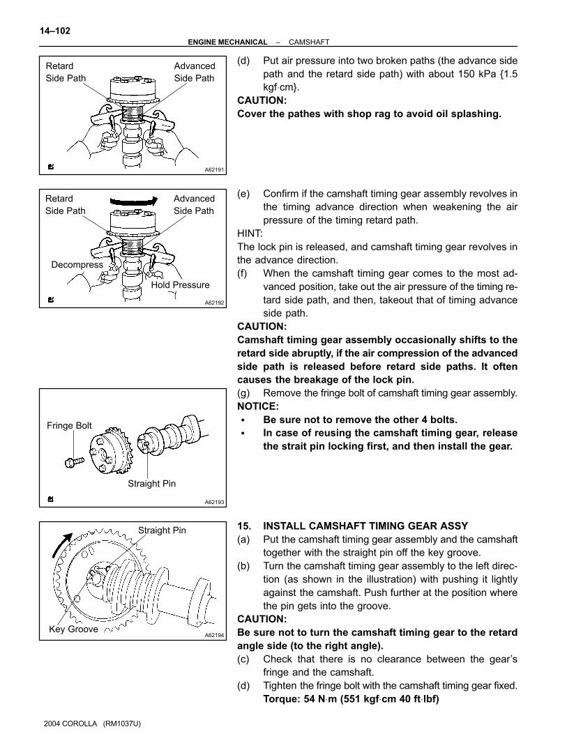
(d) Put air pressure into two broken paths (the advance side
path and the retard side path) with about 150 kPa {1.5
kgf⋅cm}.
CAUTION:
Cover the pathes with shop rag to avoid oil splashing.
(e) Confirm if the camshaft timing gear assembly revolves in
the timing advance direction when weakening the air
pressure of the timing retard path.
HINT:
The lock pin is released, and camshaft timing gear revolves in
the advance direction.
(f) When the camshaft timing gear comes to the most ad-
vanced position, take out the air pressure of the timing re-
tard side path, and then, takeout that of timing advance
side path.
CAUTION:
Camshaft timing gear assembly occasionally shifts to the
retard side abruptly, if the air compression of the advanced
side path is released before retard side paths. It often
causes the breakage of the lock pin.
(g) Remove the fringe bolt of camshaft timing gear assembly.
NOTICE:
� Be sure not to remove the other 4 bolts.
� In case of reusing the camshaft timing gear, release
the strait pin locking first, and then install the gear.
15. INSTALL CAMSHAFT TIMING GEAR ASSY
(a) Put the camshaft timing gear assembly and the camshaft
together with the straight pin off the key groove.
(b) Turn the camshaft timing gear assembly to the left direc-
tion (as shown in the illustration) with pushing it lightly
against the camshaft. Push further at the position where
the pin gets into the groove.
CAUTION:
Be sure not to turn the camshaft timing gear to the retard
angle side (to the right angle).
(c) Check that there is no clearance between the gear’s
fringe and the camshaft.
(d) Tighten the fringe bolt with the camshaft timing gear fixed.
Torque: 54 N⋅m (551 kgf⋅cm 40 ft⋅lbf)
A62195
Painted Link
Timing Mark
A62196
4 1 2 3
A62197
Painted Link
Timing Mark
A32124
–ENGINE MECHANICAL CAMSHAFT
14–103
2004 COROLLA (RM1037U)
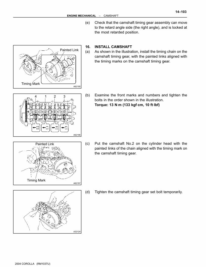
(e) Check that the camshaft timing gear assembly can move
to the retard angle side (the right angle), and is locked at
the most retarded position.
16. INSTALL CAMSHAFT
(a) As shown in the illustration, install the timing chain on the
camshaft timing gear, with the painted links aligned with
the timing marks on the camshaft timing gear.
(b) Examine the front marks and numbers and tighten the
bolts in the order shown in the illustration.
Torque: 13 N⋅m (133 kgf⋅cm, 10 ft⋅lbf)
(c) Put the camshaft No.2 on the cylinder head with the
painted links of the chain aligned with the timing mark on
the camshaft timing gear.
(d) Tighten the camshaft timing gear set bolt temporarily.

A621983 1 2 45
6
7
A62187
Fix
Tighten
A62185
Mark Mark
Mark
Timing Chain
Cover Surface
Groove
A62177
Raise
Push
Hook
Pin
14–104–ENGINE MECHANICAL CAMSHAFT
2004 COROLLA (RM1037U)
(e) Examine the front marks and numbers and tighten the
bolts in the order shown in the illustration.
Torque: 13 N⋅m (133 kgf⋅cm, 10 ft⋅lbf)
(f) Install the bearing cap No. 1.
Torque: 23 N⋅m (235 kgf⋅cm, 17 ft⋅lbf)
(g) Fix the camshaft with a wrench and so on, then tighten the
camshaft timing gear set bolt.
Torque: 54 N⋅m (551 kgf⋅cm, 40 ft⋅lbf)
NOTICE:
Be careful not damage the valve lifter.
(h) Check the match marks on the timing chain and camshaft
timing sprockets, and then the alignment of the pulley
groove with timing mark of the chain cover as shown in the
illustration.
(i) Install chain tensioner.
(1) Check the O–ring is clean, and set the hook as
shown in the illustration.
A62178
Push
A62180
Disconnect
Hook
Pin Turn
A62181
Plunger
TurnPush
A11858
–ENGINE MECHANICAL CAMSHAFT
14–105
2004 COROLLA (RM1037U)
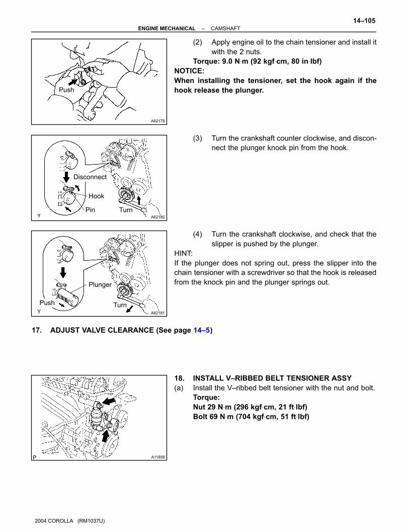
(2) Apply engine oil to the chain tensioner and install it
with the 2 nuts.
Torque: 9.0 N⋅m (92 kgf⋅cm, 80 in⋅lbf)
NOTICE:
When installing the tensioner, set the hook again if the
hook release the plunger.
(3) Turn the crankshaft counter clockwise, and discon-
nect the plunger knock pin from the hook.
(4) Turn the crankshaft clockwise, and check that the
slipper is pushed by the plunger.
HINT:
If the plunger does not spring out, press the slipper into the
chain tensioner with a screwdriver so that the hook is released
from the knock pin and the plunger springs out.
17. ADJUST VALVE CLEARANCE (See page 14–5)
18. INSTALL V–RIBBED BELT TENSIONER ASSY
(a) Install the V–ribbed belt tensioner with the nut and bolt.
Torque:
Nut 29 N⋅m (296 kgf⋅cm, 21 ft⋅lbf)
Bolt 69 N⋅m (704 kgf⋅cm, 51 ft⋅lbf)

A62182
Seal Packing
A65687
A A
A
AAA
A
A
B B
A
A64023
A64022
14–106–ENGINE MECHANICAL CAMSHAFT
2004 COROLLA (RM1037U)
19. INSTALL CYLINDER HEAD COVER SUB–ASSY
(a) Remove any old packing (FIPG) material.
(b) Apply seal packing to 2 locations as shown in the illustra-
tion.
Seal packing: Part No. 08826–00080 or equivalent
NOTICE:
� Remove any oil from the contact surface.
� Install the cylinder head cover within 3 minutes after
applying seal packing.
� Do not put into engine oil 2 hours after installing.
(c) Install the cylinder head cover and 3 cable brackets with
the 9 bolts, 2 seal washers and 2 nuts. Uniformly tighten
the bolts and nuts, in the several passes.
Torque:
A 11 N⋅m (112 kgf⋅cm, 8 ft⋅lbf)
B 9.0 N⋅m (92 kgf⋅cm, 80 in⋅lbf)
20. INSTALL IGNITION COIL ASSY
(a) Install the 4 ignition coils with the 4 bolts.
Torque: 9.0 N⋅m (92 kgf⋅cm, 80 in.⋅lbf)
21. INSTALL ENGINE WIRE
(a) Install the engine wire with the bolt and nut.
Torque: 9.0 N⋅m (92 kgf⋅cm, 80 in.⋅lbf)
A64005
A65077
–ENGINE MECHANICAL CAMSHAFT
14–107
1117
2004 COROLLA (RM1037U)
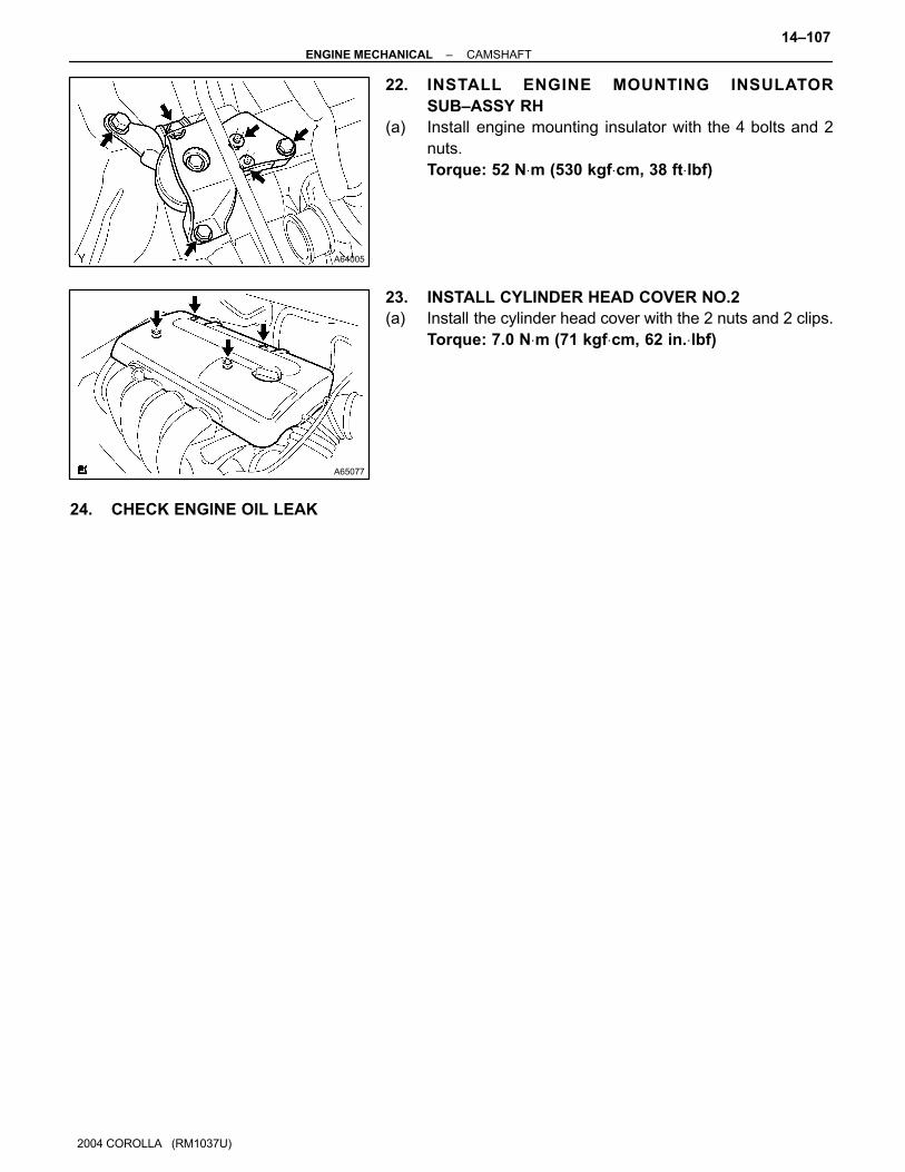
22. INSTALL ENGINE MOUNTING INSULATOR
SUB–ASSY RH
(a) Install engine mounting insulator with the 4 bolts and 2
nuts.
Torque: 52 N⋅m (530 kgf⋅cm, 38 ft⋅lbf)
23. INSTALL CYLINDER HEAD COVER NO.2
(a) Install the cylinder head cover with the 2 nuts and 2 clips.
Torque: 7.0 N⋅m (71 kgf⋅cm, 62 in.⋅lbf)
24. CHECK ENGINE OIL LEAK

140OG–01
A64042
Engine Under Cover RH
Fan and Generator V Belt
Vane Pump Assy
Generator Assy
Terminal Cap
No. 1
Cylinder Head Cover No. 2
Clip
Engine Mounting Insulator RH
N·m (kgf·cm, ft·lbf) : Specified torque
Clip
54 (551, 40)
25 (255, 18)
37 (377, 27)
7.0 (71, 62 in.⋅lbf)
52 (530, 38)
52 (530, 38)
9.8 (100, 7)
–ENGINE MECHANICAL CHAIN SUB–ASSY
14–79
2004 COROLLA (RM1037U)
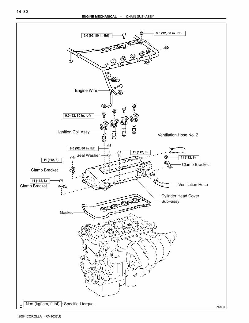
CHAIN SUB–ASSY
COMPONENTS
A64043
Ventilation Hose No. 2
Clamp Bracket
Ventilation Hose
Ignition Coil Assy
Engine Wire
Clamp Bracket
Clamp Bracket
Gasket
Cylinder Head Cover
Sub–assy
Seal Washer
N·m (kgf·cm, ft·lbf) : Specified torque
9.0 (92, 80 in.⋅lbf)9.0 (92, 80 in.⋅lbf)
9.0 (92, 80 in.⋅lbf)
9.0 (92, 80 in.⋅lbf)11 (112, 8)
11 (112, 8)11 (112, 8)
11 (112, 8)
14–80–ENGINE MECHANICAL CHAIN SUB–ASSY
1090
2004 COROLLA (RM1037U)
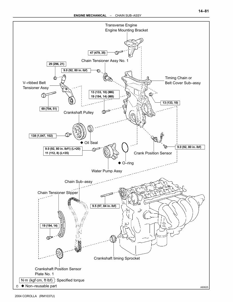
A60625
Crankshaft Pulley
V–ribbed Belt
Tensioner Assy
Water Pump Assy
Transverse Engine
Engine Mounting Bracket
Crank Position Sensor
Chain Tensioner Assy No. 1
Timing Chain or
Belt Cover Sub–assy
� Oil Seal
Crankshaft Position Sensor
Plate No. 1
Chain Sub–assy
Chain Tensioner Slipper
Crankshaft timing Sprocket
� O–ring
� Non–reusable part
N·m (kgf·cm, ft·lbf) : Specified torque
47 (479, 35)
29 (296, 21)
69 (704, 51)
138 (1,047, 102)
13 (133, 10)
9.0 (92, 80 in.⋅lbf)
9.0 (92, 80 in.⋅lbf)
19 (194, 14)
9.0 (92, 80 in.⋅lbf1) (L=20)
11 (112, 8) (L=35)
13 (133, 10) (M6)
19 (194, 14) (M8)
9.5 (97, 84 in.⋅lbf)
–ENGINE MECHANICAL CHAIN SUB–ASSY
14–81
2004 COROLLA (RM1037U)

140OH–01
A65077
A60622
A01045
A64005
14–82–ENGINE MECHANICAL CHAIN SUB–ASSY
1092
2004 COROLLA (RM1037U)
REPLACEMENT1. REMOVE ENGINE UNDER COVER RH
2. DRAIN COOLANT (See page 16–7)
3. REMOVE FRONT WHEEL RH
4. REMOVE CYLINDER HEAD COVER NO.2
(a) Remove the 2 nuts, 2 clips and cylinder head cover.
5. REMOVE FAN AND GENERATOR V BELT
(a) Turn the V–ribbed belt tensioner slowly clockwise and
loosen it. Then, remove the fan and generator V belt and
put back the V–ribbed belt tensioner little by little and fix
it quietly.
6. SEPARATE VANE PUMP ASSY (See page 51–8)
NOTICE:
Do not disconnect the hose.
7. REMOVE GENERATOR ASSY (See page 19–16)
8. REMOVE ENGINE MOUNTING INSULATOR
SUB–ASSY RH
(a) Remove the PS oil pump reservoir and put it aside.
(b) Place a wooden block between the jack and engine, and
set the jack, then remove the 4 bolts, the 2 nuts and en-
gine mounting insulator RH.

A64021
A64022
A64023
A65078
A64058
–ENGINE MECHANICAL CHAIN SUB–ASSY
14–83
2004 COROLLA (RM1037U)
9. DISCONNECT ENGINE WIRE
(a) Remove the 5 clamps from the 5 clamp brackets.
(b) Disconnect the 4 ignition coil connectors.
(c) Remove the bolt and nut installing the engine wire.
10. REMOVE IGNITION COIL ASSY
(a) Remove the 4 bolts and 4 ignition coils.
11. DISCONNECT VENTILATION HOSE
(a) Disconnect the ventilation hose from the cylinder head
cover.
12. DISCONNECT VENTILATION HOSE NO.2
(a) Disconnect the ventilation hose from the cylinder head
cover.

A64856
A62185
Mark Mark
Mark
Timing Chain
Cover Surface
Groove
A62837
SST
A11858
14–84–ENGINE MECHANICAL CHAIN SUB–ASSY
2004 COROLLA (RM1037U)
13. REMOVE CYLINDER HEAD COVER SUB–ASSY
(a) Remove the 9 bolts, 2 seal washers, 2 nuts, 3 clamp
brackets and cylinder head cover.
14. SET NO. 1 CYLINDER TO TDC/COMPRESSION
(a) Turn the crankshaft pulley, and align its groove with timing
mark ”0” of the timing chain cover.
(b) Check that the point marks of the camshaft timing sprock-
et and VVT timing sprocket are in straight line on the tim-
ing chain cover surface as shown in the illustration.
HINT:
If not, turn the crankshaft 1 revolution (360�) and align the
marks as above.
15. REMOVE CRANKSHAFT PULLEY
(a) Using SST, remove the pulley bolt.
SST 09960–10010 (09962–01000, 09963–01000)
(b) Remove the crankshaft pulley from the crankshaft.
16. REMOVE V–RIBBED BELT TENSIONER ASSY
(a) Remove the bolt, nut and V–ribbed belt tensioner.
HINT:
Handle a jack up and down to remove the bolt.

A12816
B00086
A62178
Push
A10076
–ENGINE MECHANICAL CHAIN SUB–ASSY
14–85
2004 COROLLA (RM1037U)
17. REMOVE WATER PUMP ASSY (See page 16–8)
18. REMOVE TRANSVERSE ENGINE ENGINE
MOUNTING BRACKET
(a) Remove the 3 bolts and transverse engine engine mount-
ing bracket.
19. REMOVE CRANK POSITION SENSOR
(a) Remove the 2 bolts installing the crank position sensor.
20. REMOVE CHAIN TENSIONER ASSY NO.1
(a) Remove the 2 nuts and chain tensioner.
NOTICE:
Be sure not to revolve the crankshaft without the chain ten-
sioner.
21. REMOVE TIMING CHAIN OR BELT COVER
SUB–ASSY
(a) Remove the 11 bolts and nuts.
(b) Using a torx wrench socket (E8), remove the stud bolt.
(c) Remove the timing chain cover by prying the portions be-
tween the cylinder head and cylinder block with a screw-
driver.
NOTICE:
Be careful no tot damage the contact surfaces of the timing
chain cover, cylinder head and cylinder block.

A30848
A30857
A10079
A62170
Set KeyUpward
14–86–ENGINE MECHANICAL CHAIN SUB–ASSY
2004 COROLLA (RM1037U)
22. REMOVE TIMING GEAR COVER OIL SEAL
(a) Using a screwdriver, remove the oil seal.
23. REMOVE CRANKSHAFT POSITION SENSOR PLATE NO.1
24. REMOVE CHAIN TENSIONER SLIPPER
(a) Remove the bolt and chain tensioner slipper.
25. REMOVE CHAIN SUB–ASSY
(a) Remove the timing chain with the crankshaft timing gear
plying screwdrivers as shown in the illustration.
NOTICE:
� Put shop rag to protect the engine.
� In case of revolving the camshafts with the chain off
the sprockets, turn the crankshaft 1/4 revolution for
valves not to touch the pistons.
26. INSTALL CHAIN SUB–ASSY
(a) Set No. 1 cylinder to TDC/compression.
(1) Turn the hexagonal wrench head portion of the
camshafts, and align the point marks of the cam-
shaft timing sprockets.
(2) Using a crankshaft pulley bolt, turn the crankshaft
and set the set key on the crankshaft upward.
A62171
Yellow
Color Line
Timing Mark
A62172
SST
A62173
Yellow Color Mark
Timing Mark
A30867
–ENGINE MECHANICAL CHAIN SUB–ASSY
14–87
2004 COROLLA (RM1037U)
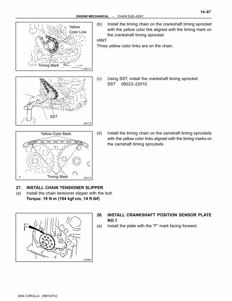
(b) Install the timing chain on the crankshaft timing sprocket
with the yellow color link aligned with the timing mark on
the crankshaft timing sprocket.
HINT:
Three yellow color links are on the chain.
(c) Using SST, install the crankshaft timing sprocket.
SST 09223–22010
(d) Install the timing chain on the camshaft timing sprockets
with the yellow color links aligned with the timing marks on
the camshaft timing sprockets.
27. INSTALL CHAIN TENSIONER SLIPPER
(a) Install the chain tensioner slipper with the bolt.
Torque: 19 N⋅m (194 kgf⋅cm, 14 ft⋅lbf)
28. INSTALL CRANKSHAFT POSITION SENSOR PLATE
NO.1
(a) Install the plate with the ”F” mark facing forward.
A62174
SST
A62175
Seal Width
4 – 5 mm
Seal Packing
A65676
Timing Chain Cover side:
3 (0.118)3 (0.118)
AA
B B
C
C
7 (0.276)
4.5 (0.177)12 (0.472) 6 (0.236)
3 (0.118)
Width 4 (0.157)
A – A B – B
C – C08826–00100 or equivalent
08826–00080 or equivalent(mm (in.))
14–88–ENGINE MECHANICAL CHAIN SUB–ASSY
2004 COROLLA (RM1037U)
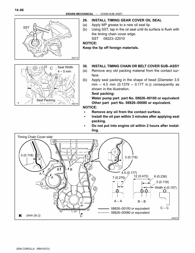
29. INSTALL TIMING GEAR COVER OIL SEAL
(a) Apply MP grease to a new oil seal lip.
(b) Using SST, tap in the oil seal until its surface is flush with
the timing chain cover edge.
SST 09223–22010
NOTICE:
Keep the lip off foreign materials.
30. INSTALL TIMING CHAIN OR BELT COVER SUB–ASSY
(a) Remove any old packing material from the contact sur-
face.
(b) Apply seal packing in the shape of bead (Diameter 3.5
mm – 4.5 mm (0.1379 – 0.177 in.)) consequently as
shown in the illustration.
Seal packing:
Water pump part part No. 08826–00100 or equivalent
Other part part No. 08826–00080 or equivalent.
NOTICE:
� Remove any oil from the contact surface.
� Install the oil pan within 3 minutes after applying seal
packing.
� Do not put into engine oil within 2 hours after instal-
ling.
A65677
A
A
A
A
A
A
AAA
B
B
B
A62177
Raise
Push
Hook
Pin
A62178
Push
B00086
–ENGINE MECHANICAL CHAIN SUB–ASSY
14–89
2004 COROLLA (RM1037U)
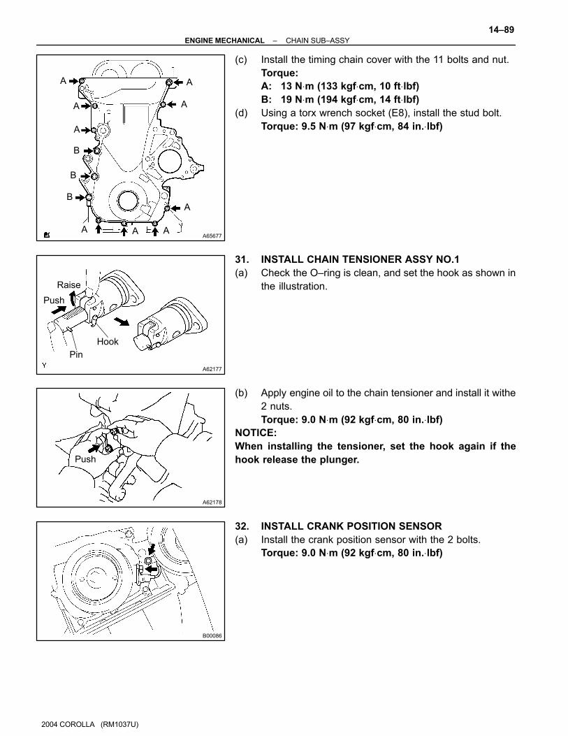
(c) Install the timing chain cover with the 11 bolts and nut.
Torque:
A: 13 N⋅m (133 kgf⋅cm, 10 ft⋅lbf)
B: 19 N⋅m (194 kgf⋅cm, 14 ft⋅lbf)
(d) Using a torx wrench socket (E8), install the stud bolt.
Torque: 9.5 N⋅m (97 kgf⋅cm, 84 in.⋅lbf)
31. INSTALL CHAIN TENSIONER ASSY NO.1
(a) Check the O–ring is clean, and set the hook as shown in
the illustration.
(b) Apply engine oil to the chain tensioner and install it withe
2 nuts.
Torque: 9.0 N⋅m (92 kgf⋅cm, 80 in.⋅lbf)
NOTICE:
When installing the tensioner, set the hook again if the
hook release the plunger.
32. INSTALL CRANK POSITION SENSOR
(a) Install the crank position sensor with the 2 bolts.
Torque: 9.0 N⋅m (92 kgf⋅cm, 80 in.⋅lbf)

A12816
A11858
A62837
SST
A62180
Disconnect
Hook
Pin Turn
14–90–ENGINE MECHANICAL CHAIN SUB–ASSY
2004 COROLLA (RM1037U)
33. INSTALL TRANSVERSE ENGINE ENGINE MOUNTING
BRACKET
(a) Install the transverse engine engine mounting bracket
with the 3 bolts.
Torque: 47 N⋅m (479 kgf⋅cm, 35 ft⋅lbf)
34. INSTALL WATER PUMP ASSY (See page 16–8)
35. INSTALL V–RIBBED BELT TENSIONER ASSY
(a) Install the V–ribbed belt tensioner with the nut and bolt.
Torque:
Nut 29 N⋅m (296 kgf⋅cm, 21 ft⋅lbf)
Bolt 69 N⋅m (704 kgf⋅cm, 51 ft⋅lbf)
36. INSTALL CRANKSHAFT PULLEY
(a) Align the pulley set key with the key groove of the pulley,
and slide on the pulley.
(b) Using SST, install the crankshaft pulley bolt.
SST 09960–10010 (09962–01000, 09963–01000)
Torque: 138 N⋅m (1,407 kgf⋅cm, 102 ft⋅lbf)
(c) Turn the crankshaft counter clockwise, and disconnect
the plunger knock pin form the hook.

A62181
Plunger
TurnPush
A62182
Seal Packing
A65687
A A A
A
AAA
A
A
B B
A64023
–ENGINE MECHANICAL CHAIN SUB–ASSY
14–91
2004 COROLLA (RM1037U)
(d) Turn the crankshaft clockwise, and check that the slipper
is pushed by the plunger.
HINT:
If the plunger does not spring out, press the slipper into the
chain tensioner with a screwdriver so that the hook is released
from the knock pin and the plunger springs out.
37. INSTALL CYLINDER HEAD COVER SUB–ASSY
(a) Remove any old pacing (FIPG) material.
(b) Apply seal packing to 2 locations as shown in the illustra-
tion.
Seal packing: Part No. 08826–00080 or equivalent
NOTICE:
� Remove any oil from the contact surface.
� Install the cylinder head cover within 3 minutes after
applying seal packing.
� Do not put into engine oil 2 hours after installing.
(c) Install the cylinder head cover and 3 cable brackets with
the 9 bolts, 2 seal washers and 2 nuts. Uniformly tighten
the bolts and nuts, in the several passes.
Torque:
A 11 N⋅m (112 kgf⋅cm, 8 ft⋅lbf)
B 9.0 N⋅m (92 kgf⋅cm, 80 in.⋅lbf)
38. INSTALL IGNITION COIL ASSY
(a) Install the 4 ignition coils with the 4 bolts.
Torque: 9.0 N⋅m (92 kgf⋅cm, 80 in.⋅lbf)
A64022
A64005
A65077
14–92–ENGINE MECHANICAL CHAIN SUB–ASSY
2004 COROLLA (RM1037U)
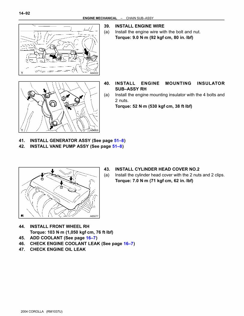
39. INSTALL ENGINE WIRE
(a) Install the engine wire with the bolt and nut.
Torque: 9.0 N⋅m (92 kgf⋅cm, 80 in.⋅lbf)
40. INSTALL ENGINE MOUNTING INSULATOR
SUB–ASSY RH
(a) Install the engine mounting insulator with the 4 bolts and
2 nuts.
Torque: 52 N⋅m (530 kgf⋅cm, 38 ft⋅lbf)
41. INSTALL GENERATOR ASSY (See page 51–8)
42. INSTALL VANE PUMP ASSY (See page 51–8)
43. INSTALL CYLINDER HEAD COVER NO.2
(a) Install the cylinder head cover with the 2 nuts and 2 clips.
Torque: 7.0 N⋅m (71 kgf⋅cm, 62 in.⋅lbf)
44. INSTALL FRONT WHEEL RH
Torque: 103 N⋅m (1,050 kgf⋅cm, 76 ft⋅lbf)
45. ADD COOLANT (See page 16–7)
46. CHECK ENGINE COOLANT LEAK (See page 16–7)
47. CHECK ENGINE OIL LEAK

140Q8–05
A84914
Compression Ring No. 1
Compression Ring No. 2
Oil Ring (Side Rail)
� Snap Ring
Piston
Piston Pin
� Snap Ring
Connecting Rod Bearing
Cylinder Block Sub–assy
Crankshaft Bearing
Crankshaft Bearing Cap Sub–assy
Crankshaft Bearing
Crankshaft Thrust Washer Upper
Key
Crankshaft
Connecting Rod Bearing
Connecting Rod Bearing Cap
Oil Ring (Expander)
See page 14–147
1st 44 (449, 33)
2nd Turn 90�
1st 20 (204, 15)
2nd Turn 90�
19 (194, 14)
� Non–reusable part
N·m (kgf·cm, ft·lbf) : Specified torque
Crankshaft
Thrust Washer Upper
Connecting Rod25 (255, 18)
Cylinder Block Water Drain Cock Sub–assy
See page 14–147
14–146–ENGINE MECHANICAL CYLINDER BLOCK ASSY (April, 2003)
2004 COROLLA (RM1037U)
CYLINDER BLOCK ASSY (April, 2003)
COMPONENTS

140OK–05
Engine Mounting Insulator RH
A64045
Engine Under Cover RH
Clip
Fan and Generator V Belt
Vane Pump Assy
Generator Assy
Terminal Cap
No. 1
Cylinder Head Cover No. 2
Clip
� Non–reusable part
N·m (kgf·cm, ft·lbf) : Specified torque
� Gasket
Exhaust pipe Assy Front
Compression Spring
EFI Fuel Pipe Clamp
54 (551, 40)
25 (255, 18)
37 (377, 27)
9.8 (100, 7) 7.0 (71, 62 in.⋅lbf)
52 (530, 38)
52 (530, 38)
43 (440, 32)
Fuel Tube Sub–assy
Air Cleaner Hose No. 1
Heater Inlet Water Hose
Radiator Hose Inlet
Union to Connector
Tube Hose
Water By–pass Hose
Water By–pass Hose No. 2
Accelerator Control
Cable Assy
14–108–ENGINE MECHANICAL CYLINDER HEAD GASKET
2004 COROLLA (RM1037U)
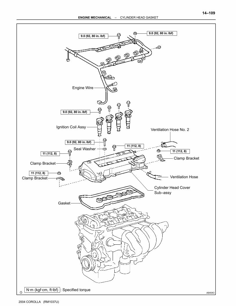
CYLINDER HEAD GASKET
COMPONENTS
A64043
Ventilation Hose No. 2
Clamp Bracket
Ventilation Hose
Ignition Coil Assy
Engine Wire
Clamp Bracket
Clamp Bracket
Gasket
Cylinder Head Cover
Sub–assy
Seal Washer
N·m (kgf·cm, ft·lbf) : Specified torque
9.0 (92, 80 in.⋅lbf)9.0 (92, 80 in.⋅lbf)
9.0 (92, 80 in.⋅lbf)
9.0 (92, 80 in.⋅lbf)
11 (112, 8)
11 (112, 8)11 (112, 8)
11 (112, 8)
–ENGINE MECHANICAL CYLINDER HEAD GASKET
14–109
2004 COROLLA (RM1037U)

A60628
Crankshaft Pulley
V–ribbed Belt
Tensioner Assy
Water Pump Assy
Transverse Engine
Engine Mounting Bracket
Crank Position Sensor
Chain Tensioner Assy No. 1
Timing Chain or
Belt Cover Sub–assy
� Oil Seal
Crankshaft Position Sensor
Plate No. 1
Chain Sub–assy
Chain Tensioner Slipper
Crankshaft timing Sprocket
� O–ring
� Non–reusable part
N·m (kgf·cm, ft·lbf) : Specified torque
Chain Vibration
Damper No. 1
47 (479, 35)
29 (296, 21)
69 (704, 51)
138 (1,047, 102)
13 (133, 10)
9.0 (92, 80 in.⋅lbf)
9.0 (92, 80 in.⋅lbf)
19 (194, 14)
9.0 (92, 80 in.⋅lbf)
9 (92, 80 in.⋅lbf1) (L=20)
11 (112, 8) (L=35)
13 (133, 10) (M6)
19 (194, 14) (M8)
9.5 (97, 84 in.⋅lbf)
14–110–ENGINE MECHANICAL CYLINDER HEAD GASKET
2004 COROLLA (RM1037U)

A64046
Camshaft
Camshaft No. 2
Plate Washer
Camshaft Bearing Cap No. 1
Camshaft Bearing Cap No. 3
Cylinder Head Sub–assy
Camshaft Timing Oil Control Valve Assy
� O–ring
� Cylinder Head Gasket
Manifold Stay
Intake Manifold
Clamp Bracket
Oil Level Gage Guide
� O–ring
Oil Level Gage
Sub–assy
� Non–reusable part
N·m (kgf·cm, ft·lbf) : Specified torque
13 (133, 10)
23 (235, 17)
30 (306, 22)13 (133, 10)
9.0 (92, 80 in.⋅lbf)
1st 49 (500, 36)
2nd Turn 90�
See page 14–112
49 (500, 36)
9.0 (92, 80 in.⋅lbf)
� Gasket
–ENGINE MECHANICAL CYLINDER HEAD GASKET
14–111
2004 COROLLA (RM1037U)
140OL–01
A65077
A60622
14–112–ENGINE MECHANICAL CYLINDER HEAD GASKET
2004 COROLLA (RM1037U)
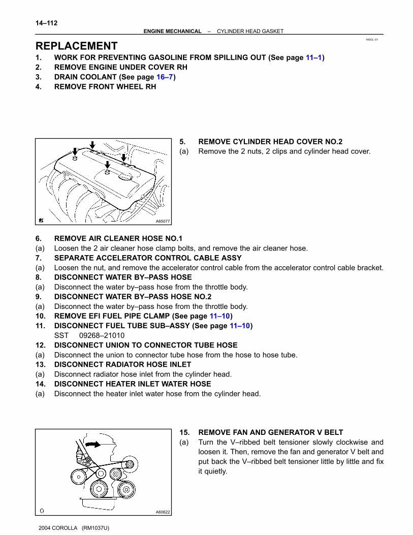
REPLACEMENT1. WORK FOR PREVENTING GASOLINE FROM SPILLING OUT (See page 11–1)
2. REMOVE ENGINE UNDER COVER RH
3. DRAIN COOLANT (See page 16–7)
4. REMOVE FRONT WHEEL RH
5. REMOVE CYLINDER HEAD COVER NO.2
(a) Remove the 2 nuts, 2 clips and cylinder head cover.
6. REMOVE AIR CLEANER HOSE NO.1
(a) Loosen the 2 air cleaner hose clamp bolts, and remove the air cleaner hose.
7. SEPARATE ACCELERATOR CONTROL CABLE ASSY
(a) Loosen the nut, and remove the accelerator control cable from the accelerator control cable bracket.
8. DISCONNECT WATER BY–PASS HOSE
(a) Disconnect the water by–pass hose from the throttle body.
9. DISCONNECT WATER BY–PASS HOSE NO.2
(a) Disconnect the water by–pass hose from the throttle body.
10. REMOVE EFI FUEL PIPE CLAMP (See page 11–10)
11. DISCONNECT FUEL TUBE SUB–ASSY (See page 11–10)
SST 09268–21010
12. DISCONNECT UNION TO CONNECTOR TUBE HOSE
(a) Disconnect the union to connector tube hose from the hose to hose tube.
13. DISCONNECT RADIATOR HOSE INLET
(a) Disconnect radiator hose inlet from the cylinder head.
14. DISCONNECT HEATER INLET WATER HOSE
(a) Disconnect the heater inlet water hose from the cylinder head.
15. REMOVE FAN AND GENERATOR V BELT
(a) Turn the V–ribbed belt tensioner slowly clockwise and
loosen it. Then, remove the fan and generator V belt and
put back the V–ribbed belt tensioner little by little and fix
it quietly.

A01045
A64005
A64021
A64022
–ENGINE MECHANICAL CYLINDER HEAD GASKET
14–113
2004 COROLLA (RM1037U)
16. SEPARATE VANE PUMP ASSY (See page 51–8)
NOTICE:
Do not disconnect the hose.
17. REMOVE GENERATOR ASSY (See page 19–16)
18. SEPARATE EXHAUST PIPE ASSY FRONT
(a) Remove the 2 bolts, 2 compression spring installing the front side of exhaust pipe.
(b) Remove the gasket.
19. REMOVE ENGINE MOUNTING INSULATOR
SUB–ASSY RH
(a) Remove the PS oil pump reservoir and put it aside.
(b) Place a wooden block between the jack and engine, and
set the jack, then remove the 4 bolts, the 2 nuts and en-
gine mounting insulator RH.
20. DISCONNECT ENGINE WIRE
(a) Remove the 5 clamps from the 5 clamp brackets.
(b) Disconnect the 4 ignition coil connectors.
(c) Remove the bolt and nut installing the engine wire.
A64023
A65078
A64058
A64856
14–114–ENGINE MECHANICAL CYLINDER HEAD GASKET
2004 COROLLA (RM1037U)
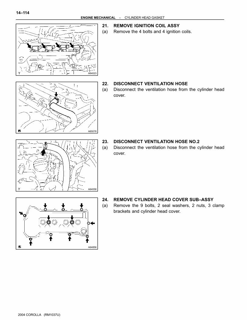
21. REMOVE IGNITION COIL ASSY
(a) Remove the 4 bolts and 4 ignition coils.
22. DISCONNECT VENTILATION HOSE
(a) Disconnect the ventilation hose from the cylinder head
cover.
23. DISCONNECT VENTILATION HOSE NO.2
(a) Disconnect the ventilation hose from the cylinder head
cover.
24. REMOVE CYLINDER HEAD COVER SUB–ASSY
(a) Remove the 9 bolts, 2 seal washers, 2 nuts, 3 clamp
brackets and cylinder head cover.
A62185
Mark Mark
Mark
Timing Chain
Cover Surface
Groove
A62837
SST
A11858
–ENGINE MECHANICAL CYLINDER HEAD GASKET
14–115
2004 COROLLA (RM1037U)
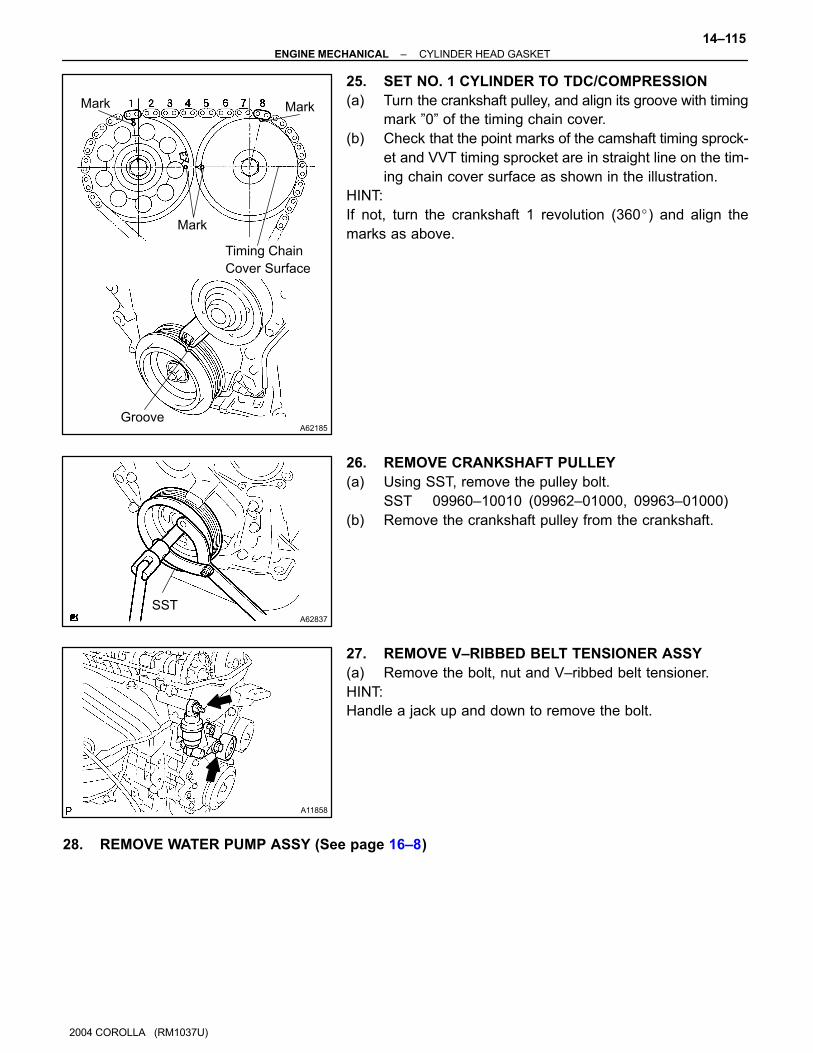
25. SET NO. 1 CYLINDER TO TDC/COMPRESSION
(a) Turn the crankshaft pulley, and align its groove with timing
mark ”0” of the timing chain cover.
(b) Check that the point marks of the camshaft timing sprock-
et and VVT timing sprocket are in straight line on the tim-
ing chain cover surface as shown in the illustration.
HINT:
If not, turn the crankshaft 1 revolution (360�) and align the
marks as above.
26. REMOVE CRANKSHAFT PULLEY
(a) Using SST, remove the pulley bolt.
SST 09960–10010 (09962–01000, 09963–01000)
(b) Remove the crankshaft pulley from the crankshaft.
27. REMOVE V–RIBBED BELT TENSIONER ASSY
(a) Remove the bolt, nut and V–ribbed belt tensioner.
HINT:
Handle a jack up and down to remove the bolt.
28. REMOVE WATER PUMP ASSY (See page 16–8)

A12816
B00086
A62178
Push
A10076
A30848
14–116–ENGINE MECHANICAL CYLINDER HEAD GASKET
1126
2004 COROLLA (RM1037U)
29. REMOVE TRANSVERSE ENGINE ENGINE
MOUNTING BRACKET
(a) Remove the 3 bolts and transverse engine engine mount-
ing bracket.
30. REMOVE CRANK POSITION SENSOR
(a) Remove the 2 bolts installing the crank position sensor.
31. REMOVE CHAIN TENSIONER ASSY NO.1
(a) Remove the 2 nuts and chain tensioner.
NOTICE:
Be sure not to revolve the crankshaft without the chain ten-
sioner.
32. REMOVE TIMING CHAIN OR BELT COVER
SUB–ASSY
(a) Remove the 11 bolts and nuts.
(b) Using a torx wrench socket (E8), remove the stud bolt.
(c) Remove the timing chain cover by prying the portions be-
tween the cylinder head and cylinder block with a screw-
driver.
NOTICE:
Be careful no tot damage the contact surfaces of the timing
chain cover, cylinder head and cylinder block.
33. REMOVE TIMING GEAR COVER OIL SEAL
(a) Using a screwdriver, remove the oil seal.
A30857
A14660
A64026
–ENGINE MECHANICAL CYLINDER HEAD GASKET
14–117
2004 COROLLA (RM1037U)
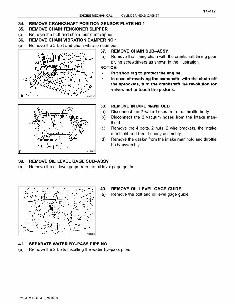
34. REMOVE CRANKSHAFT POSITION SENSOR PLATE NO.1
35. REMOVE CHAIN TENSIONER SLIPPER
(a) Remove the bolt and chain tensioner slipper.
36. REMOVE CHAIN VIBRATION DAMPER NO.1
(a) Remove the 2 bolt and chain vibration damper.
37. REMOVE CHAIN SUB–ASSY
(a) Remove the timing chain with the crankshaft timing gear
plying screwdrivers as shown in the illustration.
NOTICE:
� Put shop rag to protect the engine.
� In case of revolving the camshafts with the chain off
the sprockets, turn the crankshaft 1/4 revolution for
valves not to touch the pistons.
38. REMOVE INTAKE MANIFOLD
(a) Disconnect the 2 water hoses from the throttle body.
(b) Disconnect the 2 vacuum hoses from the intake man-
ihold.
(c) Remove the 4 bolts, 2 nuts, 2 wire brackets, the intake
manihold and throttle body assembly.
(d) Remove the gasket from the intake manihold and throttle
body assembly.
39. REMOVE OIL LEVEL GAGE SUB–ASSY
(a) Remove the oil level gage from the oil level gage guide.
40. REMOVE OIL LEVEL GAGE GUIDE
(a) Remove the bolt and oil level gage guide.
41. SEPARATE WATER BY–PASS PIPE NO.1
(a) Remove the 2 bolts installing the water by–pass pipe.
A62814
42 5 3 1
B06777
A64030
A62816
2
5
3
1 10 8 4
7 9 6
14–118–ENGINE MECHANICAL CYLINDER HEAD GASKET
1128
2004 COROLLA (RM1037U)
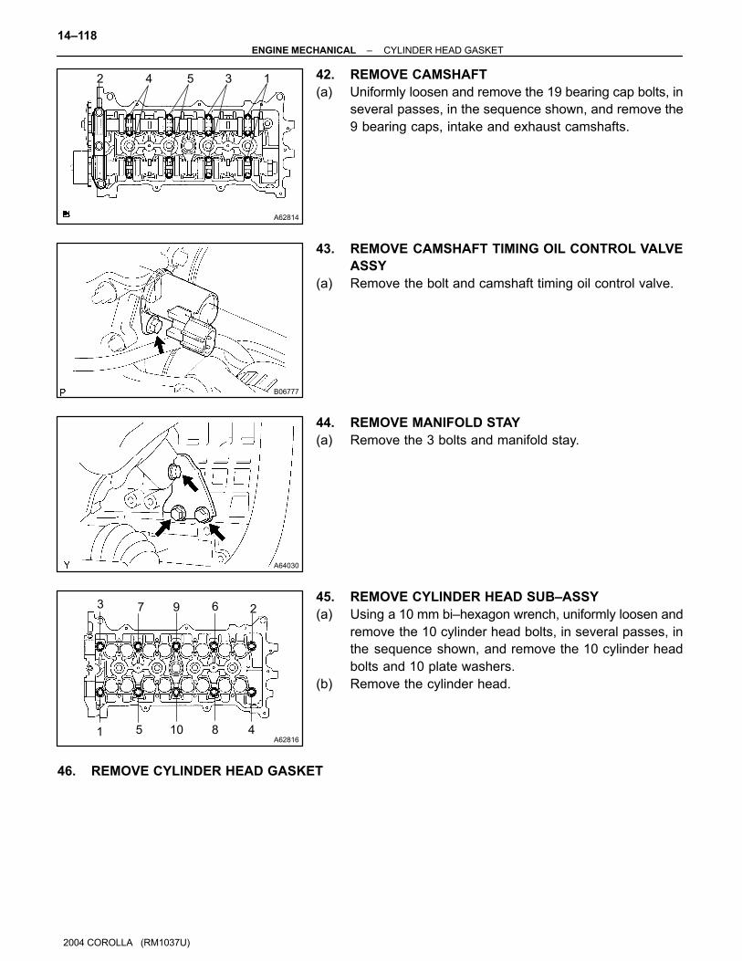
42. REMOVE CAMSHAFT
(a) Uniformly loosen and remove the 19 bearing cap bolts, in
several passes, in the sequence shown, and remove the
9 bearing caps, intake and exhaust camshafts.
43. REMOVE CAMSHAFT TIMING OIL CONTROL VALVE
ASSY
(a) Remove the bolt and camshaft timing oil control valve.
44. REMOVE MANIFOLD STAY
(a) Remove the 3 bolts and manifold stay.
45. REMOVE CYLINDER HEAD SUB–ASSY
(a) Using a 10 mm bi–hexagon wrench, uniformly loosen and
remove the 10 cylinder head bolts, in several passes, in
the sequence shown, and remove the 10 cylinder head
bolts and 10 plate washers.
(b) Remove the cylinder head.
46. REMOVE CYLINDER HEAD GASKET
A62827
Lot No.
A62820
Overall Length
A62816
8 4 2 5 9
731610
A62823
Paint Mark90�
Front
A64030
–ENGINE MECHANICAL CYLINDER HEAD GASKET
14–119
2004 COROLLA (RM1037U)
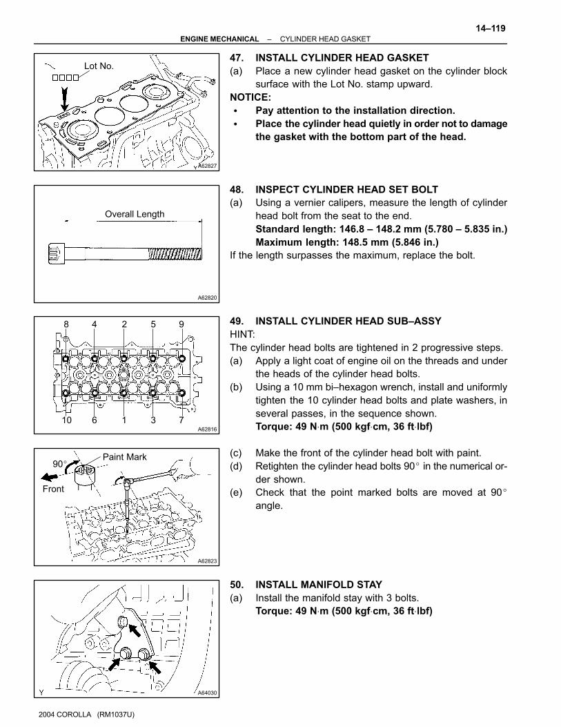
47. INSTALL CYLINDER HEAD GASKET
(a) Place a new cylinder head gasket on the cylinder block
surface with the Lot No. stamp upward.
NOTICE:
� Pay attention to the installation direction.
� Place the cylinder head quietly in order not to damage
the gasket with the bottom part of the head.
48. INSPECT CYLINDER HEAD SET BOLT
(a) Using a vernier calipers, measure the length of cylinder
head bolt from the seat to the end.
Standard length: 146.8 – 148.2 mm (5.780 – 5.835 in.)
Maximum length: 148.5 mm (5.846 in.)
If the length surpasses the maximum, replace the bolt.
49. INSTALL CYLINDER HEAD SUB–ASSY
HINT:
The cylinder head bolts are tightened in 2 progressive steps.
(a) Apply a light coat of engine oil on the threads and under
the heads of the cylinder head bolts.
(b) Using a 10 mm bi–hexagon wrench, install and uniformly
tighten the 10 cylinder head bolts and plate washers, in
several passes, in the sequence shown.
Torque: 49 N⋅m (500 kgf⋅cm, 36 ft⋅lbf)
(c) Make the front of the cylinder head bolt with paint.
(d) Retighten the cylinder head bolts 90� in the numerical or-
der shown.
(e) Check that the point marked bolts are moved at 90�
angle.
50. INSTALL MANIFOLD STAY
(a) Install the manifold stay with 3 bolts.
Torque: 49 N⋅m (500 kgf⋅cm, 36 ft⋅lbf)
B06777
A62150
A62825
6 2 4 8
5 1 3 7
11
10
9
A64026
14–120–ENGINE MECHANICAL CYLINDER HEAD GASKET
2004 COROLLA (RM1037U)
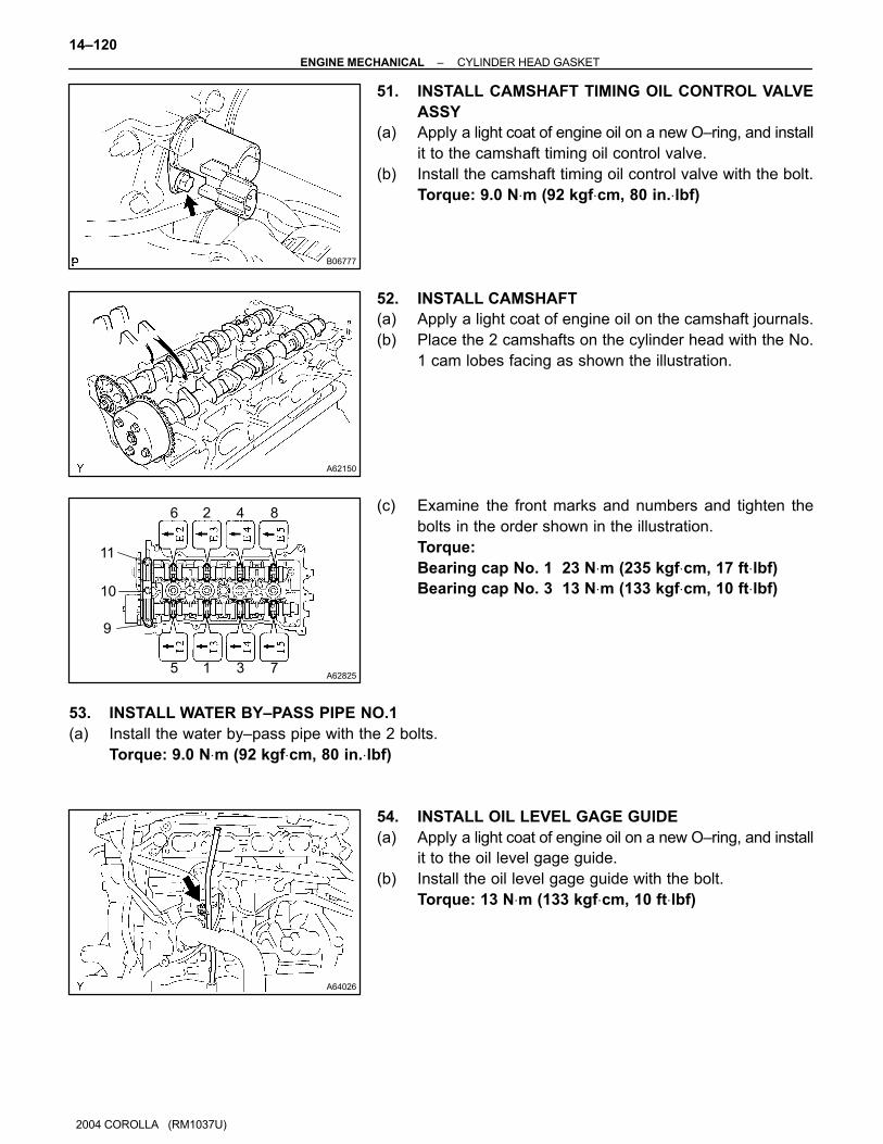
51. INSTALL CAMSHAFT TIMING OIL CONTROL VALVE
ASSY
(a) Apply a light coat of engine oil on a new O–ring, and install
it to the camshaft timing oil control valve.
(b) Install the camshaft timing oil control valve with the bolt.
Torque: 9.0 N⋅m (92 kgf⋅cm, 80 in.⋅lbf)
52. INSTALL CAMSHAFT
(a) Apply a light coat of engine oil on the camshaft journals.
(b) Place the 2 camshafts on the cylinder head with the No.
1 cam lobes facing as shown the illustration.
(c) Examine the front marks and numbers and tighten the
bolts in the order shown in the illustration.
Torque:
Bearing cap No. 1 23 N⋅m (235 kgf⋅cm, 17 ft⋅lbf)
Bearing cap No. 3 13 N⋅m (133 kgf⋅cm, 10 ft⋅lbf)
53. INSTALL WATER BY–PASS PIPE NO.1
(a) Install the water by–pass pipe with the 2 bolts.
Torque: 9.0 N⋅m (92 kgf⋅cm, 80 in.⋅lbf)
54. INSTALL OIL LEVEL GAGE GUIDE
(a) Apply a light coat of engine oil on a new O–ring, and install
it to the oil level gage guide.
(b) Install the oil level gage guide with the bolt.
Torque: 13 N⋅m (133 kgf⋅cm, 10 ft⋅lbf)
A14660
A10079
A62170
Set KeyUpward
A62171
Yellow
Color Line
Timing Mark
A62172
SST
–ENGINE MECHANICAL CYLINDER HEAD GASKET
14–121
2004 COROLLA (RM1037U)
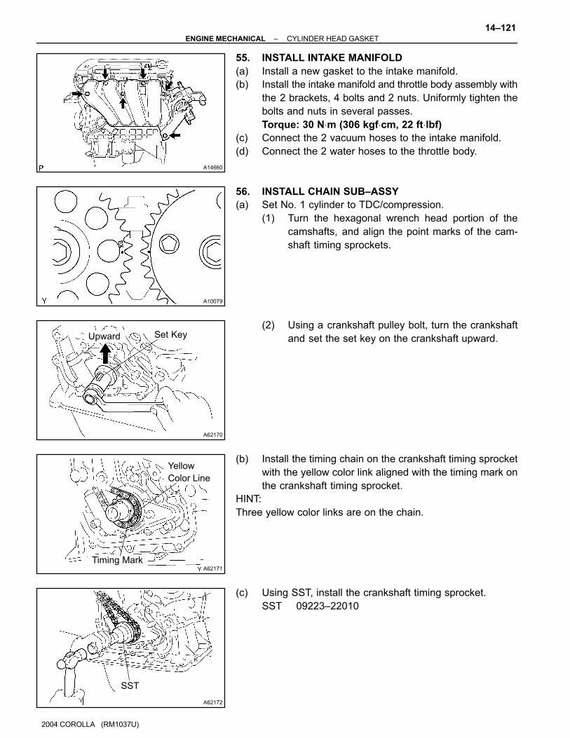
55. INSTALL INTAKE MANIFOLD
(a) Install a new gasket to the intake manifold.
(b) Install the intake manifold and throttle body assembly with
the 2 brackets, 4 bolts and 2 nuts. Uniformly tighten the
bolts and nuts in several passes.
Torque: 30 N⋅m (306 kgf⋅cm, 22 ft⋅lbf)
(c) Connect the 2 vacuum hoses to the intake manifold.
(d) Connect the 2 water hoses to the throttle body.
56. INSTALL CHAIN SUB–ASSY
(a) Set No. 1 cylinder to TDC/compression.
(1) Turn the hexagonal wrench head portion of the
camshafts, and align the point marks of the cam-
shaft timing sprockets.
(2) Using a crankshaft pulley bolt, turn the crankshaft
and set the set key on the crankshaft upward.
(b) Install the timing chain on the crankshaft timing sprocket
with the yellow color link aligned with the timing mark on
the crankshaft timing sprocket.
HINT:
Three yellow color links are on the chain.
(c) Using SST, install the crankshaft timing sprocket.
SST 09223–22010

A62173
Yellow Color Mark
Timing Mark
A30867
A62174
SST
14–122–ENGINE MECHANICAL CYLINDER HEAD GASKET
2004 COROLLA (RM1037U)
(d) Install the timing chain on the camshaft timing sprockets
with the yellow color links aligned with the timing marks on
the camshaft timing sprockets.
57. INSTALL CHAIN VIBRATION DAMPER NO.1
(a) Install the chain vibration damper with the 2 bolts.
Torque: 9.0 N⋅m (92 kgf⋅cm, 80 in.⋅lbf)
58. INSTALL CHAIN TENSIONER SLIPPER
(a) Install the chain tensioner slipper with the bolt.
Torque: 19 N⋅m (194 kgf⋅cm, 14 ft⋅lbf)
59. INSTALL CRANKSHAFT POSITION SENSOR PLATE
NO.1
(a) Install the plate with the ”F” mark facing forward.
60. INSTALL TIMING GEAR COVER OIL SEAL
(a) Apply MP grease to a new oil seal lip.
(b) Using SST, tap in the oil seal until its surface is flush with
the timing chain cover edge.
SST 09223–22010
NOTICE:
Keep the lip off foreign materials.
A62175
Seal Width
4 – 5 mm
Seal Packing
A65676
Timing Chain Cover side:
3 (0.118)3 (0.118)
AA
B B
C
C
7 (0.276)
4.5 (0.177)12 (0.472) 6 (0.236)
3 (0.118)
Width 4 (0.157)
A – A B – B
C – C08826–00100 or equivalent
08826–00080 or equivalent(mm (in.))
A65677
A
A
A
A
A
A
AAA
B
B
B
–ENGINE MECHANICAL CYLINDER HEAD GASKET
14–123
2004 COROLLA (RM1037U)
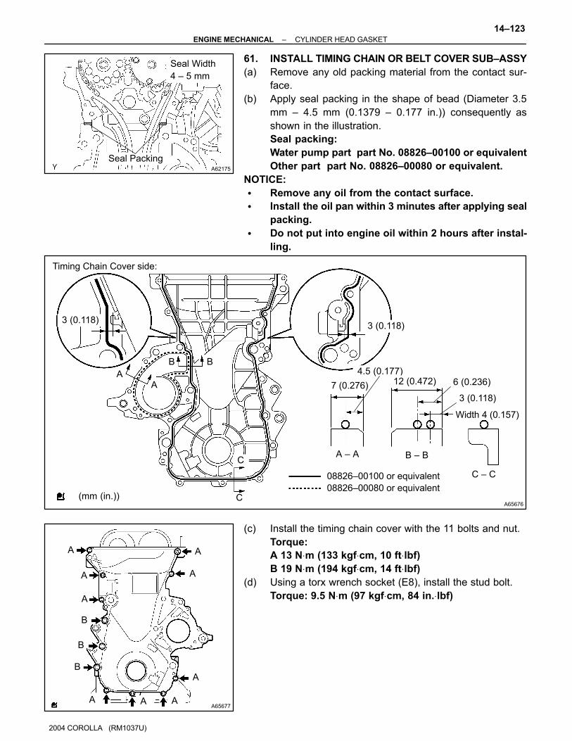
61. INSTALL TIMING CHAIN OR BELT COVER SUB–ASSY
(a) Remove any old packing material from the contact sur-
face.
(b) Apply seal packing in the shape of bead (Diameter 3.5
mm – 4.5 mm (0.1379 – 0.177 in.)) consequently as
shown in the illustration.
Seal packing:
Water pump part part No. 08826–00100 or equivalent
Other part part No. 08826–00080 or equivalent.
NOTICE:
� Remove any oil from the contact surface.
� Install the oil pan within 3 minutes after applying seal
packing.
� Do not put into engine oil within 2 hours after instal-
ling.
(c) Install the timing chain cover with the 11 bolts and nut.
Torque:
A 13 N⋅m (133 kgf⋅cm, 10 ft⋅lbf)
B 19 N⋅m (194 kgf⋅cm, 14 ft⋅lbf)
(d) Using a torx wrench socket (E8), install the stud bolt.
Torque: 9.5 N⋅m (97 kgf⋅cm, 84 in.⋅lbf)
A62177
Raise
Push
Hook
Pin
A62178
Push
B00086
A12816
14–124–ENGINE MECHANICAL CYLINDER HEAD GASKET
2004 COROLLA (RM1037U)
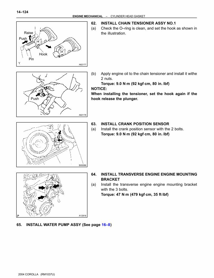
62. INSTALL CHAIN TENSIONER ASSY NO.1
(a) Check the O–ring is clean, and set the hook as shown in
the illustration.
(b) Apply engine oil to the chain tensioner and install it withe
2 nuts.
Torque: 9.0 N⋅m (92 kgf⋅cm, 80 in.⋅lbf)
NOTICE:
When installing the tensioner, set the hook again if the
hook release the plunger.
63. INSTALL CRANK POSITION SENSOR
(a) Install the crank position sensor with the 2 bolts.
Torque: 9.0 N⋅m (92 kgf⋅cm, 80 in.⋅lbf)
64. INSTALL TRANSVERSE ENGINE ENGINE MOUNTING
BRACKET
(a) Install the transverse engine engine mounting bracket
with the 3 bolts.
Torque: 47 N⋅m (479 kgf⋅cm, 35 ft⋅lbf)
65. INSTALL WATER PUMP ASSY (See page 16–8)
A11858
A62837
SST
A62180
Disconnect
Hook
Pin Turn
A62181
Plunger
TurnPush
A62182
Seal Packing
–ENGINE MECHANICAL CYLINDER HEAD GASKET
14–125
2004 COROLLA (RM1037U)
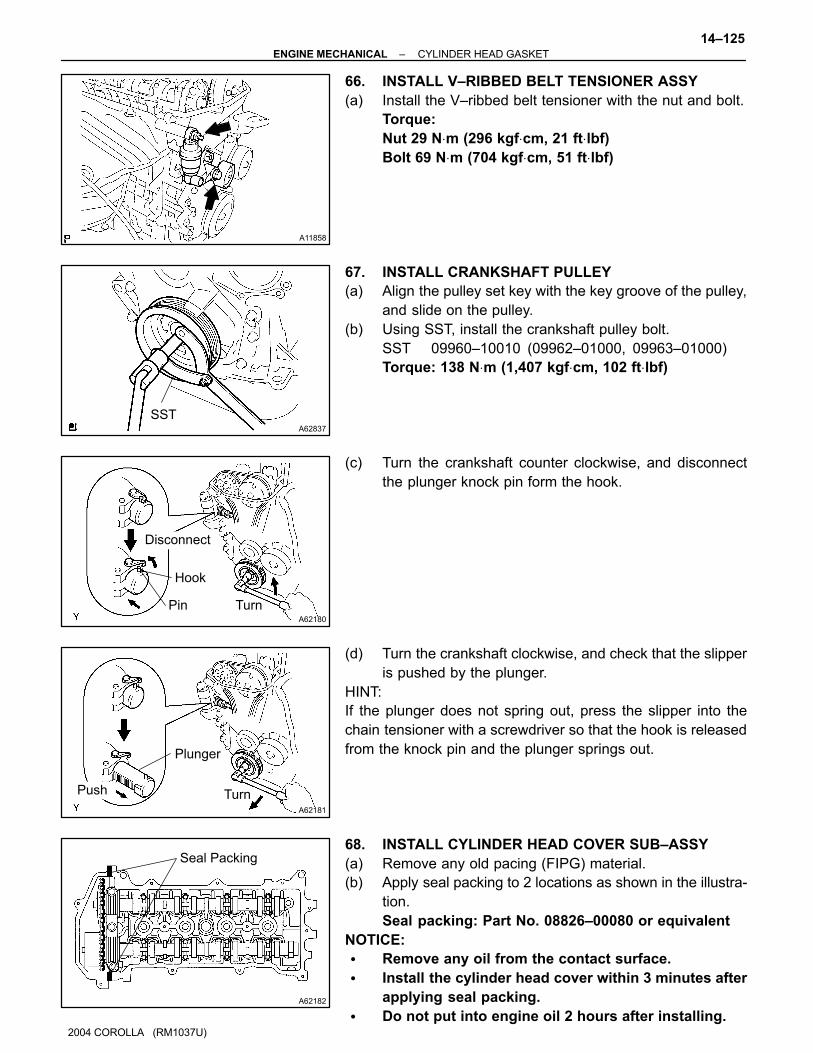
66. INSTALL V–RIBBED BELT TENSIONER ASSY
(a) Install the V–ribbed belt tensioner with the nut and bolt.
Torque:
Nut 29 N⋅m (296 kgf⋅cm, 21 ft⋅lbf)
Bolt 69 N⋅m (704 kgf⋅cm, 51 ft⋅lbf)
67. INSTALL CRANKSHAFT PULLEY
(a) Align the pulley set key with the key groove of the pulley,
and slide on the pulley.
(b) Using SST, install the crankshaft pulley bolt.
SST 09960–10010 (09962–01000, 09963–01000)
Torque: 138 N⋅m (1,407 kgf⋅cm, 102 ft⋅lbf)
(c) Turn the crankshaft counter clockwise, and disconnect
the plunger knock pin form the hook.
(d) Turn the crankshaft clockwise, and check that the slipper
is pushed by the plunger.
HINT:
If the plunger does not spring out, press the slipper into the
chain tensioner with a screwdriver so that the hook is released
from the knock pin and the plunger springs out.
68. INSTALL CYLINDER HEAD COVER SUB–ASSY
(a) Remove any old pacing (FIPG) material.
(b) Apply seal packing to 2 locations as shown in the illustra-
tion.
Seal packing: Part No. 08826–00080 or equivalent
NOTICE:
� Remove any oil from the contact surface.
� Install the cylinder head cover within 3 minutes after
applying seal packing.
� Do not put into engine oil 2 hours after installing.

A65687
A A
A
AAAA
A
B B
A
A64023
A64022
A64005
14–126–ENGINE MECHANICAL CYLINDER HEAD GASKET
1136
2004 COROLLA (RM1037U)
(c) Install the cylinder head cover and 3 cable brackets with
the 9 bolts, 2 seal washers and 2 nuts. Uniformly tighten
the bolts and nuts, in the several passes.
Torque:
A 11 N⋅m (112 kgf⋅cm, 8 ft⋅lbf)
B 9.0 N⋅m (92 kgf⋅cm, 80 in.⋅lbf)
69. INSTALL IGNITION COIL ASSY
(a) Install the 4 ignition coils with the 4 bolts.
Torque: 9.0 N⋅m (92 kgf⋅cm, 80 in.⋅lbf)
70. INSTALL ENGINE WIRE
(a) Install the engine wire with the bolt and nut.
Torque: 9.0 N⋅m (92 kgf⋅cm, 80 in.⋅lbf)
71. INSTALL ENGINE MOUNTING INSULATOR
SUB–ASSY RH
(a) Install the engine mounting insulator with the 4 bolts and
2 nuts.
Torque: 52 N⋅m (530 kgf⋅cm, 38 ft⋅lbf)

A65077
–ENGINE MECHANICAL CYLINDER HEAD GASKET
14–127
2004 COROLLA (RM1037U)
72. INSTALL EXHAUST PIPE ASSY FRONT (See page 15–2)
73. INSTALL VANE PUMP ASSY (See page 51–8)
74. INSTALL GENERATOR ASSY (See page 19–16)
75. INSTALL CYLINDER HEAD COVER NO.2
(a) Install the cylinder head cover with the 2 nuts and 2 clips.
Torque: 7.0 N⋅m (71 kgf⋅cm, 62 in.⋅lbf)
76. INSTALL FRONT WHEEL RH
Torque: 103 N⋅m (1,050 kgf⋅cm, 76 ft⋅lbf)
77. ADD COOLANT (See page 16–7)
78. INSPECT COMPRESSION (See page 14–1)
SST 09992–00500
79. INSPECT CO/HC (See page 14–1)
80. INSPECT IGNITION TIMING (See page 14–1)
SST 09843–18040
81. CHECK ENGINE COOLANT LEAK (See page 16–7)
82. CHECK ENGINE OIL LEAK
140Q6–02
A62766
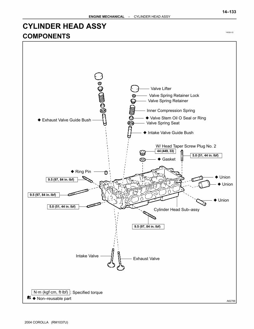
� Exhaust Valve Guide Bush
W/ Head Taper Screw Plug No. 2
� Gasket
Intake ValveExhaust Valve
Cylinder Head Sub–assy
Valve Lifter
Valve Spring Retainer Lock
Valve Spring Retainer
Inner Compression Spring
� Valve Stem Oil O Seal or Ring
Valve Spring Seat
� Intake Valve Guide Bush
� Non–reusable part
N·m (kgf·cm, ft·lbf) : Specified torque
44 (449, 33)
9.5 (97, 84 in.⋅lbf)
9.5 (97, 84 in.⋅lbf)
5.0 (51, 44 in.⋅lbf)
9.5 (97, 84 in.⋅lbf)
� Ring Pin
5.0 (51, 44 in.⋅lbf)
� Union
� Union
� Union
–ENGINE MECHANICAL CYLINDER HEAD ASSY
14–133
2004 COROLLA (RM1037U)
CYLINDER HEAD ASSY
COMPONENTS

140Q7–04
A62890
A62891
A65688
SST
Wooden
Block
A62893
14–134–ENGINE MECHANICAL CYLINDER HEAD ASSY
2004 COROLLA (RM1037U)
OVERHAUL
1. REMOVE W/HEAD TAPER SCREW PLUG NO.2
(a) Using a socket hexagon wench 10, remove the taper
screw plug and gasket.
2. REMOVE VALVE LIFTER
(a) Remove the valve lifters from the cylinder head.
3. REMOVE VALVE
(a) Place the cylinder head on wooden blocks.
(b) Using SST, compress the inner compression spring and
remove the 2 valve spring retainer locks.
SST 09202–70020 (09202–00010, 09202–01010,
09202–01020)
(c) Remove the valve spring retainers, inner compression
springs and valves from the cylinder head.
4. VALVE STEM OIL O SEAL OR RING
(a) Using a needle–nose pliers, remove the valve stem oil
seals.
A62894
A65689
Front side:
Upper side:
Intake side:Exhaust side:
A65690
Cylinder block side:
Intake manifold side:
Exhaust manifold side:
–ENGINE MECHANICAL CYLINDER HEAD ASSY
14–135
2004 COROLLA (RM1037U)
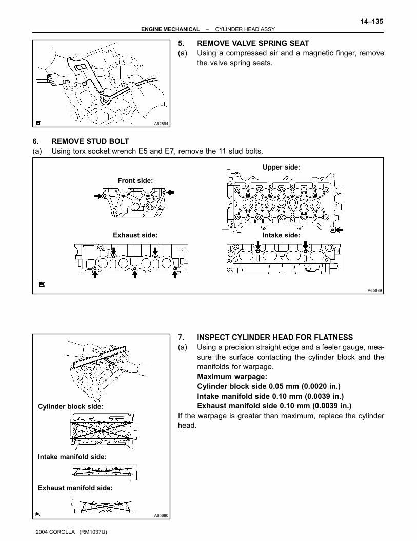
5. REMOVE VALVE SPRING SEAT
(a) Using a compressed air and a magnetic finger, remove
the valve spring seats.
6. REMOVE STUD BOLT
(a) Using torx socket wrench E5 and E7, remove the 11 stud bolts.
7. INSPECT CYLINDER HEAD FOR FLATNESS
(a) Using a precision straight edge and a feeler gauge, mea-
sure the surface contacting the cylinder block and the
manifolds for warpage.
Maximum warpage:
Cylinder block side 0.05 mm (0.0020 in.)
Intake manifold side 0.10 mm (0.0039 in.)
Exhaust manifold side 0.10 mm (0.0039 in.)
If the warpage is greater than maximum, replace the cylinder
head.

A62897
A62786
Width
A62787
1.0 – 1.4 mm
(0.039 – 0.055 in.)
30�
45�
14–136–ENGINE MECHANICAL CYLINDER HEAD ASSY
1146
2004 COROLLA (RM1037U)
8. INSPECT CYLINDER HEAD FOR CRACKS
(a) Using a dye penetrate, check the combustion chamber,
intake ports, exhaust ports and cylinder block surface for
cracks.
9. INSPECT VALVE SEATS
(a) Apply a light coat of prussian blue (or white lead) to the
valve face.
(b) Lightly press the valve against the seat.
NOTICE:
Do not rotate valve.
(c) Check the valve face and seat according to the following
procedure.
(1) If blue appears 360� around the face, the valve is
concentric. If not, replace the valve.
(2) If blue appears 360� around the valve seat, the
guide and face are concentric. If not, resurface the
seat.
(3) Check that the seat contact is in the middle of the
valve face with the width between 1.0 – 1.4 mm
(0.039 – 0.055 in.).
10. REPAIR VALVE SEATS
NOTICE:
Take off a cutter gradually to make smooth valve seats.
(a) If the seating is too high on the valve face, use 30� and
45� cutters to correct the seat.
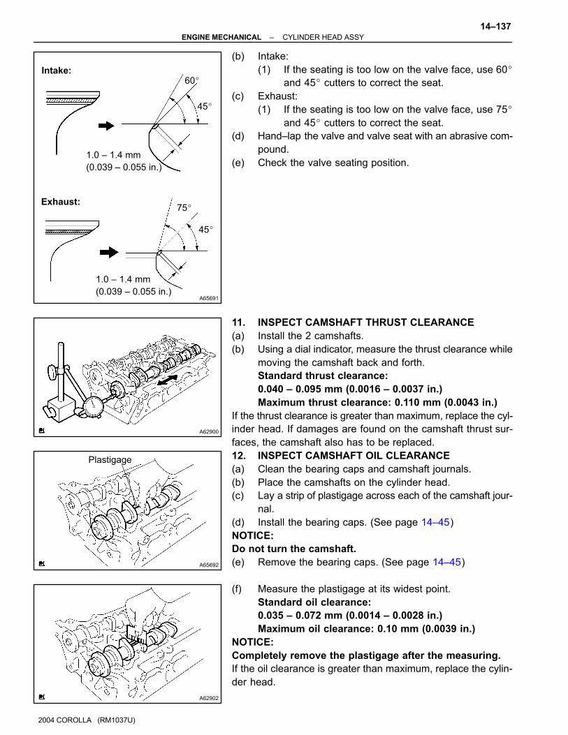
A65691
1.0 – 1.4 mm
(0.039 – 0.055 in.)
75�
45�
1.0 – 1.4 mm
(0.039 – 0.055 in.)
60�
45�
Intake:
Exhaust:
A62900
A65692
Plastigage
A62902
–ENGINE MECHANICAL CYLINDER HEAD ASSY
14–137
2004 COROLLA (RM1037U)
(b) Intake:
(1) If the seating is too low on the valve face, use 60�
and 45� cutters to correct the seat.
(c) Exhaust:
(1) If the seating is too low on the valve face, use 75�
and 45� cutters to correct the seat.
(d) Hand–lap the valve and valve seat with an abrasive com-
pound.
(e) Check the valve seating position.
11. INSPECT CAMSHAFT THRUST CLEARANCE
(a) Install the 2 camshafts.
(b) Using a dial indicator, measure the thrust clearance while
moving the camshaft back and forth.
Standard thrust clearance:
0.040 – 0.095 mm (0.0016 – 0.0037 in.)
Maximum thrust clearance: 0.110 mm (0.0043 in.)
If the thrust clearance is greater than maximum, replace the cyl-
inder head. If damages are found on the camshaft thrust sur-
faces, the camshaft also has to be replaced.
12. INSPECT CAMSHAFT OIL CLEARANCE
(a) Clean the bearing caps and camshaft journals.
(b) Place the camshafts on the cylinder head.
(c) Lay a strip of plastigage across each of the camshaft jour-
nal.
(d) Install the bearing caps. (See page 14–45)
NOTICE:
Do not turn the camshaft.
(e) Remove the bearing caps. (See page 14–45)
(f) Measure the plastigage at its widest point.
Standard oil clearance:
0.035 – 0.072 mm (0.0014 – 0.0028 in.)
Maximum oil clearance: 0.10 mm (0.0039 in.)
NOTICE:
Completely remove the plastigage after the measuring.
If the oil clearance is greater than maximum, replace the cylin-
der head.

P16860
A62903
EM0801
A62784
Deviation
14–138–ENGINE MECHANICAL CYLINDER HEAD ASSY
2004 COROLLA (RM1037U)
13. INSPECT VALVE LIFTER
(a) Using a micrometer, measure the valve lifter diameter.
Lifter diameter:
30.966 – 30.976 mm (1.2191 – 1.2195 in.)
14. INSPECT VALVE LIFTER OIL CLEARANCE
(a) Using a caliper gauge, measure the valve lifter bore diam-
eter of the cylinder head.
Lifter bore diameter:
31.000 – 31.025 mm (1.2205 – 1.2215 in.)
(b) Subtract the valve lifter diameter measurement from the
valve lifter bore diameter measurement.
Standard oil clearance:
0.024 – 0.059 mm (0.0009 – 0.0023 in.)
Maximum oil clearance: 0.079 mm (0.0031 in.)
If the oil clearance is greater than maximum, replace the valve
lifter.
If necessary, replace the cylinder head.
15. INSPECT INNER COMPRESSION SPRING
(a) Using a vernier caliper, measure the free length of the in-
ner compression spring.
Free length: 43.40 mm (1.7087 in.)
(b) Using a steel square, measure the deviation of the inner
compression spring.
Maximum deviation: 1.6 mm (0.063 in.)
Maximum angle (reference): 2�
If the deviation is greater than maximum, replace the inner com-
pression spring.
EM0281
EM2534
Overall
length
A62783
A62785
Margin
Thickness
A62905
–ENGINE MECHANICAL CYLINDER HEAD ASSY
14–139
2004 COROLLA (RM1037U)
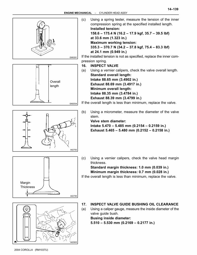
(c) Using a spring tester, measure the tension of the inner
compression spring at the specified installed length.
Installed tension:
158.6 – 175.4 N (16.2 – 17.9 kgf, 35.7 – 39.5 lbf)
at 33.6 mm (1.323 in.)
Maximum working tension:
335.3 – 370.7 N (34.2 – 37.8 kgf, 75.4 – 83.3 lbf)
at 24.1 mm (0.949 in.)
If the installed tension is not as specified, replace the inner com-
pression spring.
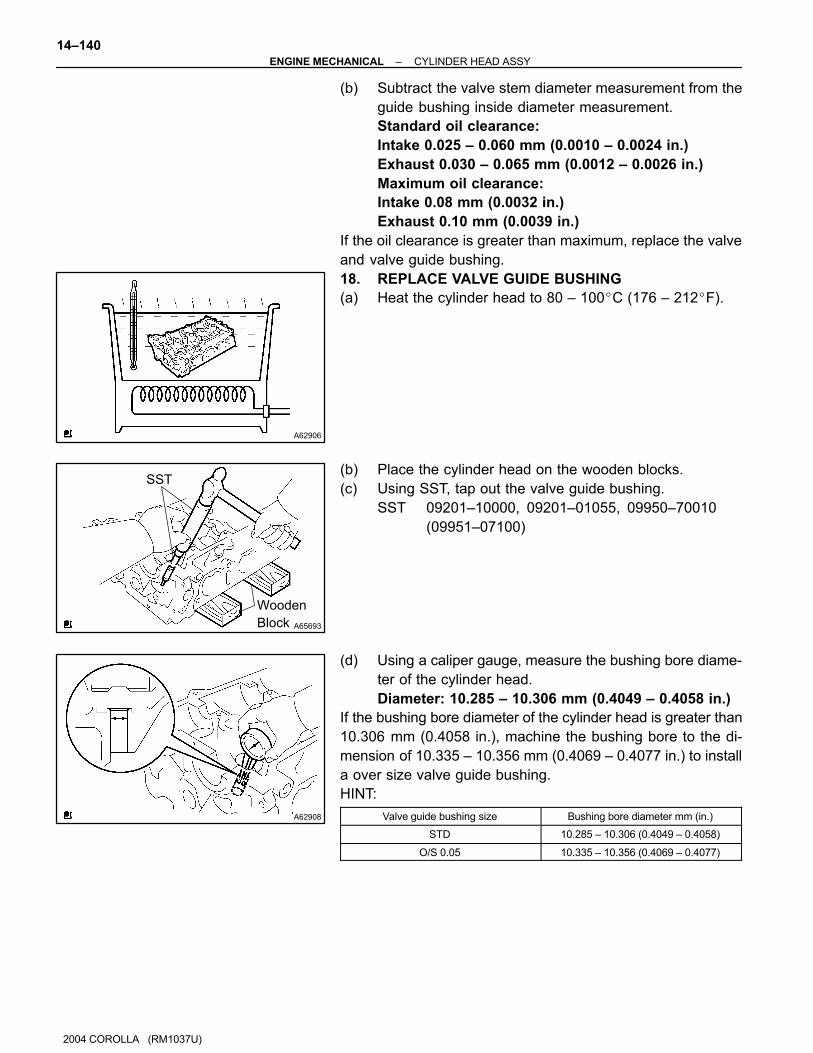
16. INSPECT VALVE
(a) Using a vernier calipers, check the valve overall length.
Standard overall length:
Intake 88.65 mm (3.4902 in.)
Exhaust 88.69 mm (3.4917 in.)
Minimum overall length:
Intake 88.35 mm (3.4784 in.)
Exhaust 88.39 mm (3.4799 in.)
If the overall length is less than minimum, replace the valve.
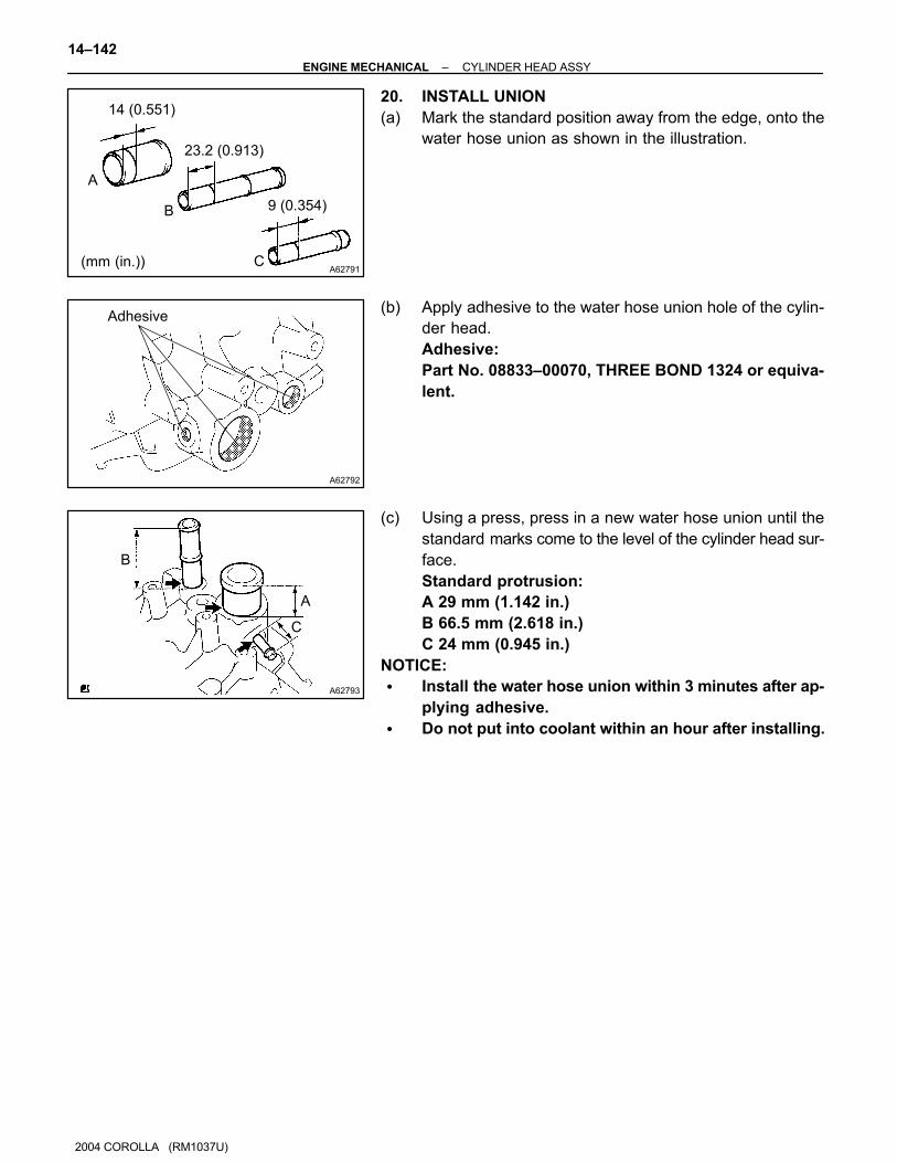
(b) Using a micrometer, measure the diameter of the valve
stem.
Valve stem diameter:
Intake 5.470 – 5.485 mm (0.2154 – 0.2159 in.)
Exhaust 5.465 – 5.480 mm (0.2152 – 0.2158 in.)
(c) Using a vernier calipers, check the valve head margin
thickness.
Standard margin thickness: 1.0 mm (0.039 in.)
Minimum margin thickness: 0.7 mm (0.028 in.)
If the overall length is less than minimum, replace the valve.
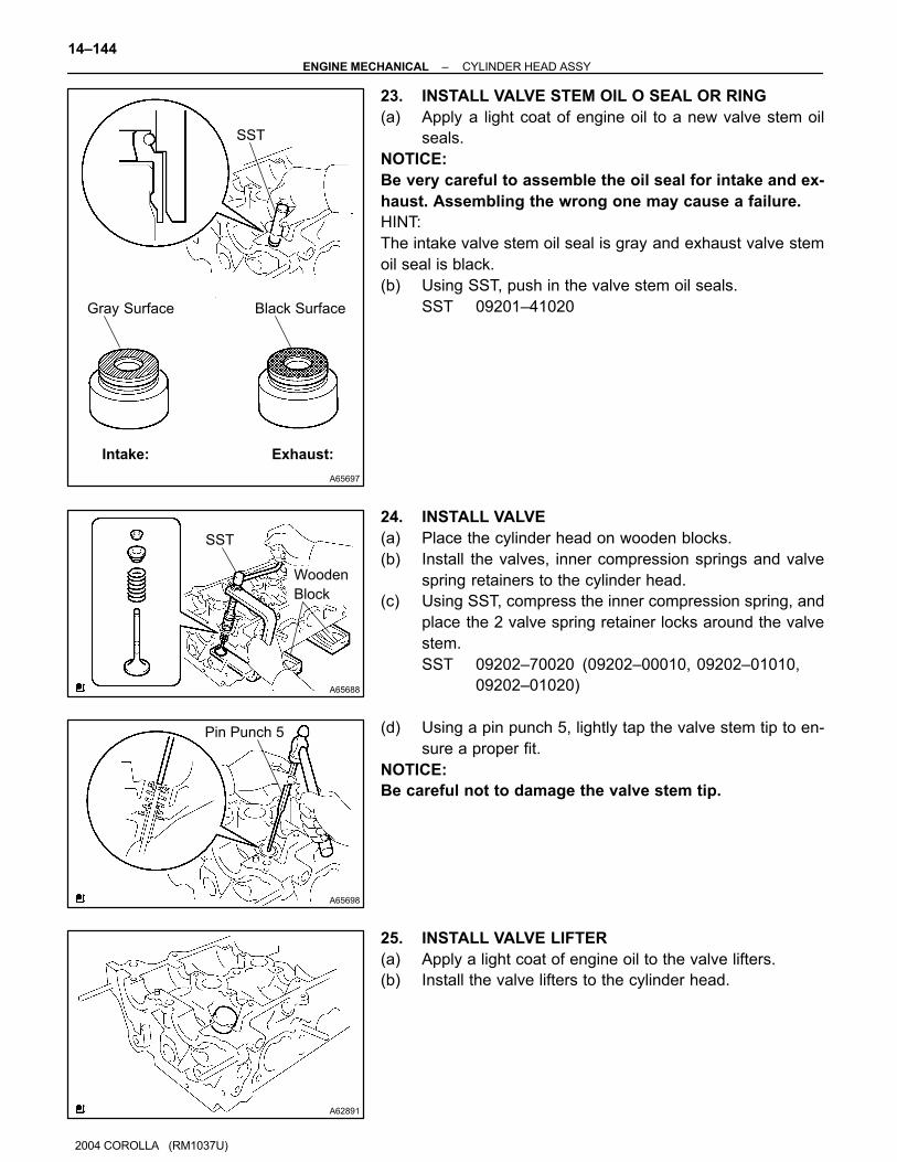
17. INSPECT VALVE GUIDE BUSHING OIL CLEARANCE
(a) Using a caliper gauge, measure the inside diameter of the
valve guide bush.
Busing inside diameter:
5.510 – 5.530 mm (0.2169 – 0.2177 in.)
A62906
A65693
SST
Wooden
Block
A62908
14–140–ENGINE MECHANICAL CYLINDER HEAD ASSY
2004 COROLLA (RM1037U)
(b) Subtract the valve stem diameter measurement from the
guide bushing inside diameter measurement.
Standard oil clearance:
Intake 0.025 – 0.060 mm (0.0010 – 0.0024 in.)
Exhaust 0.030 – 0.065 mm (0.0012 – 0.0026 in.)
Maximum oil clearance:
Intake 0.08 mm (0.0032 in.)
Exhaust 0.10 mm (0.0039 in.)
If the oil clearance is greater than maximum, replace the valve
and valve guide bushing.
18. REPLACE VALVE GUIDE BUSHING
(a) Heat the cylinder head to 80 – 100�C (176 – 212�F).
(b) Place the cylinder head on the wooden blocks.
(c) Using SST, tap out the valve guide bushing.
SST 09201–10000, 09201–01055, 09950–70010
(09951–07100)
(d) Using a caliper gauge, measure the bushing bore diame-
ter of the cylinder head.
Diameter: 10.285 – 10.306 mm (0.4049 – 0.4058 in.)
If the bushing bore diameter of the cylinder head is greater than
10.306 mm (0.4058 in.), machine the bushing bore to the di-
mension of 10.335 – 10.356 mm (0.4069 – 0.4077 in.) to install
a over size valve guide bushing.
HINT:
Valve guide bushing size Bushing bore diameter mm (in.)
STD 10.285 – 10.306 (0.4049 – 0.4058)
O/S 0.05 10.335 – 10.356 (0.4069 – 0.4077)

A62906
A65694
SST
Wooden
Block
A65582
A65695
6
(mm (in.))
145 (0.197)
–ENGINE MECHANICAL CYLINDER HEAD ASSY
14–141
2004 COROLLA (RM1037U)
(e) Heat the cylinder head to 80 – 100�C (176 – 212�F).
(f) Place the cylinder head on wooden blocks.
(g) Using SST, tap in a new valve guide bushing to the speci-
fied protrusion height.
SST 09201–10000, 09201–01055, 09950–70010
(09951–07100)
Protrusion height: 8.7 – 9.1 mm (0.343 – 0.358 in.)
(h) Using a sharp 5.5 mm reamer, ream the valve guide bush-
ing to obtain the standard specified clearance.
Standard oil clearance:
Intake 0.025 – 0.060 mm (0.0010 – 0.0024 in.)
Exhaust 0.030 – 0.065 mm (0.0012 – 0.0026 in.)
19. INSTALL STRAIGHT PIN
(a) Using a plastic hammer, install the new 2 straight pins.
Standard protrusion: 5 mm (0.197 in.)
A62791
14 (0.551)
23.2 (0.913)
9 (0.354)
A
B
C(mm (in.))
A62792
Adhesive
A62793
B
A
C
14–142–ENGINE MECHANICAL CYLINDER HEAD ASSY
2004 COROLLA (RM1037U)
20. INSTALL UNION
(a) Mark the standard position away from the edge, onto the
water hose union as shown in the illustration.
(b) Apply adhesive to the water hose union hole of the cylin-
der head.
Adhesive:
Part No. 08833–00070, THREE BOND 1324 or equiva-
lent.
(c) Using a press, press in a new water hose union until the
standard marks come to the level of the cylinder head sur-
face.
Standard protrusion:
A 29 mm (1.142 in.)
B 66.5 mm (2.618 in.)
C 24 mm (0.945 in.)
NOTICE:
� Install the water hose union within 3 minutes after ap-
plying adhesive.
� Do not put into coolant within an hour after installing.

A65696
Front side:
Exhaust side: Intake side:
Upper side:
A B
D E
C
A B C D E
(mm)
20
16
93.5
30
9
53.5 15
12
38.5
18
16
40.5
24
49.5
13
A65581
–ENGINE MECHANICAL CYLINDER HEAD ASSY
14–143
2004 COROLLA (RM1037U)
21. INSTALL STUD BOLT
(a) Using torx socket wrench E5 and E7, install the 11 stud bolts,
Torque:
Stud bolt A, D and E 9.5 N⋅m (97 kgf⋅cm, 84 in.⋅lbf)
Stud bolt B and C 5.0 N⋅m (51 kgf⋅cm, 44 in.⋅lbf)
22. INSTALL VALVE SPRING SEAT
(a) Install the valve spring seats to the cylinder head.
A65697
SST
Exhaust:Intake:
Gray Surface Black Surface
A65688
SST
Wooden
Block
A65698
Pin Punch 5
A62891
14–144–ENGINE MECHANICAL CYLINDER HEAD ASSY
2004 COROLLA (RM1037U)
23. INSTALL VALVE STEM OIL O SEAL OR RING
(a) Apply a light coat of engine oil to a new valve stem oil
seals.
NOTICE:
Be very careful to assemble the oil seal for intake and ex-
haust. Assembling the wrong one may cause a failure.
HINT:
The intake valve stem oil seal is gray and exhaust valve stem
oil seal is black.
(b) Using SST, push in the valve stem oil seals.
SST 09201–41020
24. INSTALL VALVE
(a) Place the cylinder head on wooden blocks.
(b) Install the valves, inner compression springs and valve
spring retainers to the cylinder head.
(c) Using SST, compress the inner compression spring, and
place the 2 valve spring retainer locks around the valve
stem.
SST 09202–70020 (09202–00010, 09202–01010,
09202–01020)
(d) Using a pin punch 5, lightly tap the valve stem tip to en-
sure a proper fit.
NOTICE:
Be careful not to damage the valve stem tip.
25. INSTALL VALVE LIFTER
(a) Apply a light coat of engine oil to the valve lifters.
(b) Install the valve lifters to the cylinder head.
A62890
–ENGINE MECHANICAL CYLINDER HEAD ASSY
14–145
2004 COROLLA (RM1037U)
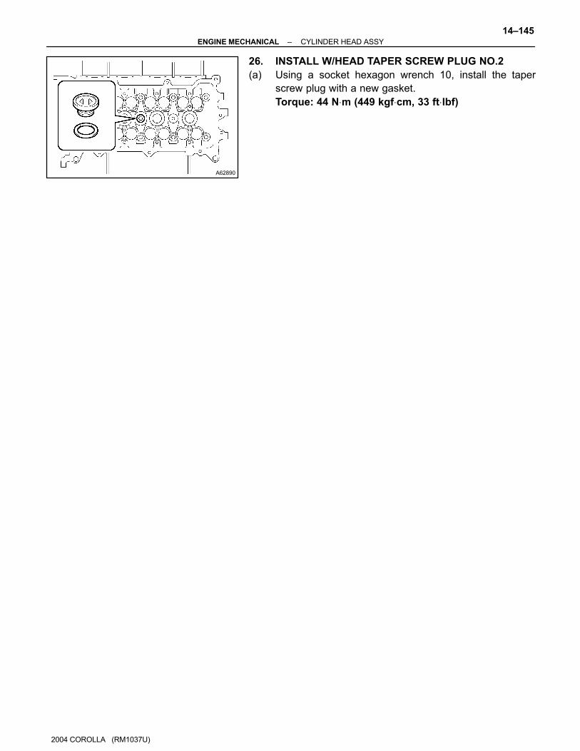
26. INSTALL W/HEAD TAPER SCREW PLUG NO.2
(a) Using a socket hexagon wrench 10, install the taper
screw plug with a new gasket.
Torque: 44 N⋅m (449 kgf⋅cm, 33 ft⋅lbf)
140OC–03
A62199
TC
CG
A64072
–ENGINE MECHANICAL ENGINE ASSEMBLY
14–1
2004 COROLLA (RM1037U)
ENGINE ASSEMBLY
INSPECTION1. INSPECT COOLANT (See page 16–1)
2. INSPECT ENGINE OIL (See page 17–1)
3. INSPECT BATTERY (See page 19–13)
4. INSPECT AIR CLEANER FILTER ELEMENT SUB–ASSY
5. INSPECT SPARK PLUG (See page 18–2)
6. INSPECT FAN AND GENERATOR V BELT
HINT:
You don’t need to check the belt deflection because auto tensioner is adopted.
7. INSPECT IGNITION TIMING
(a) Warm up engine.
(b) When using hand–held tester or OBDII scan tool.
(1) Connect the hand–held tester or OBDII scan tool to
the DLC3.
HINT:
Please refer to the hand–held tester or OBDII scan tool opera-
tor’s manual for further details.
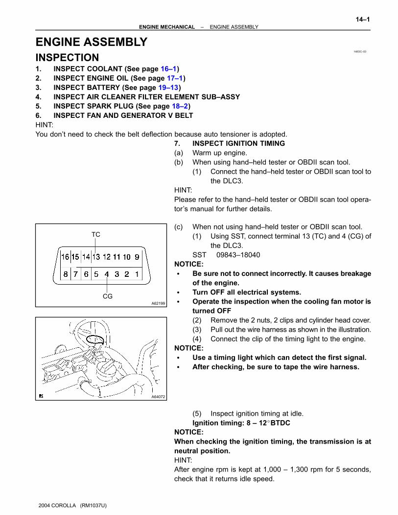
(c) When not using hand–held tester or OBDII scan tool.
(1) Using SST, connect terminal 13 (TC) and 4 (CG) of
the DLC3.
SST 09843–18040
NOTICE:
� Be sure not to connect incorrectly. It causes breakage
of the engine.
� Turn OFF all electrical systems.
� Operate the inspection when the cooling fan motor is
turned OFF
(2) Remove the 2 nuts, 2 clips and cylinder head cover.
(3) Pull out the wire harness as shown in the illustration.
(4) Connect the clip of the timing light to the engine.
NOTICE:
� Use a timing light which can detect the first signal.
� After checking, be sure to tape the wire harness.
(5) Inspect ignition timing at idle.
Ignition timing: 8 – 12�BTDC
NOTICE:
When checking the ignition timing, the transmission is at
neutral position.
HINT:
After engine rpm is kept at 1,000 – 1,300 rpm for 5 seconds,
check that it returns idle speed.

A01037
14–2–ENGINE MECHANICAL ENGINE ASSEMBLY
2004 COROLLA (RM1037U)
(6) Disconnect the terminal 13 (TC) and 4 (CG) of the
DLC3.
(7) Inspect ignition timing at idle.
Ignition timing: 10 – 18 �BTDC
(8) Confirm that ignition timing moves to advanced
angle side when the engine rpm is increased.
(9) Remove the timing light.
(10) Install cylinder head cover No.2 with the 2 nuts and
2 clips.
Torque: 7.0 N⋅m (71 kgf⋅cm, 62 in.⋅lbf)
8. INSPECT ENGINE IDLE SPEED
(a) Warm up engine.
(b) When using hand–held tester or OBDII scan tool.
(1) Connect the hand–held tester or OBDII scan tool to the DLC3.
HINT:
Please refer to the hand – held tester or OBDII scan tool operator’s manual for further details.
(c) Check the idle speed.
Idle speed: 650 – 750 rpm
NOTICE:
� Check idle speed with cooling fan OFF.
� Switch off all accessories and air conditioning.
9. INSPECT COMPRESSION
(a) Warm up and stop engine.
(b) Remove ignition coil.
(c) Remove spark plugs.
(d) Inspect cylinder compression pressure.
SST 09992–00500
(1) Insert a compression gauge into the spark plug
hole.
(2) Fully open the throttle.
(3) While cranking the engine, measure the compres-
sion pressure.
Compression pressure
1,300 kPa (13.3 kgf⋅cm2, 189 psi)
Minimum pressure: 1,000 kPa (10.2 kgf⋅cm2, 145 psi)
Difference between each cylinder:
100 kPa (1.0 kgf⋅cm2, 15 psi)
NOTICE:
� Always use a fully charged battery to obtain engine
speed of 250 rpm or more.
� Check other cylinder’s compression pressure in the
same way.
� This measurement must be done in as short a time as
possible.
–ENGINE MECHANICAL ENGINE ASSEMBLY
14–3
2004 COROLLA (RM1037U)
(4) If the cylinder compression in one more cylinders is
low, pour a small amount of engine oil into the cylin-
der through the spark plug hole and repeat steps (1)
through (3) for cylinders with low compression.
HINT:
� If adding oil helps the compression, it is likely that the pis-
ton rings and/or cylinder bore are worn or damaged.
� If pressure stays low, a valve may be sticking or seating
is improper, or there may be leakage past the gasket.
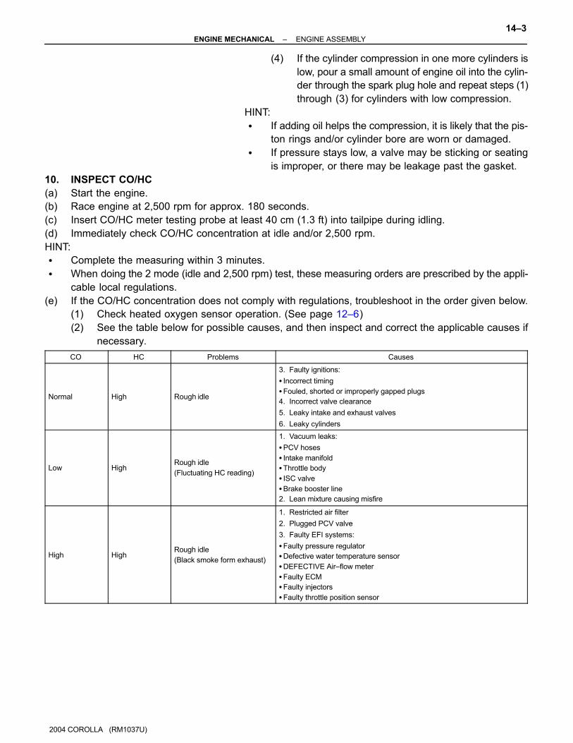
10. INSPECT CO/HC
(a) Start the engine.
(b) Race engine at 2,500 rpm for approx. 180 seconds.
(c) Insert CO/HC meter testing probe at least 40 cm (1.3 ft) into tailpipe during idling.
(d) Immediately check CO/HC concentration at idle and/or 2,500 rpm.
HINT:
� Complete the measuring within 3 minutes.
� When doing the 2 mode (idle and 2,500 rpm) test, these measuring orders are prescribed by the appli-
cable local regulations.
(e) If the CO/HC concentration does not comply with regulations, troubleshoot in the order given below.
(1) Check heated oxygen sensor operation. (See page 12–6)
(2) See the table below for possible causes, and then inspect and correct the applicable causes if
necessary.
CO HC Problems Causes
Normal High Rough idle
3. Faulty ignitions:
� Incorrect timing
�Fouled, shorted or improperly gapped plugs
4. Incorrect valve clearance
5. Leaky intake and exhaust valves
6. Leaky cylinders
Low HighRough idle
(Fluctuating HC reading)
1. Vacuum leaks:
�PCV hoses
� Intake manifold
�Throttle body
� ISC valve
�Brake booster line
2. Lean mixture causing misfire
High HighRough idle
(Black smoke form exhaust)
1. Restricted air filter
2. Plugged PCV valve
3. Faulty EFI systems:
�Faulty pressure regulator
�Defective water temperature sensor
�DEFECTIVE Air–flow meter
�Faulty ECM
�Faulty injectors
�Faulty throttle position sensor
140ON–01
A62838SST
A62838SST
A62202
Cut Position
A62203
SST
14–130–ENGINE MECHANICAL ENGINE REAR OIL SEAL
2004 COROLLA (RM1037U)
ENGINE REAR OIL SEAL
REPLACEMENT1. REMOVE MANUAL TRANSAXLE ASSY (M/T TRANSAXLE) (See page 41–17)
2. REMOVE AUTOMATIC TRANSAXLE ASSY (A/T TRANSAXLE) (See page 40–9)
3. REMOVE CLUTCH COVER ASSY (M/T TRANSAXLE) (See page 42–18)
(a) Remove the 6 bolts and clutch cover.
4. REMOVE CLUTCH DISC ASSY (M/T TRANSAXLE) (See page 42–18)
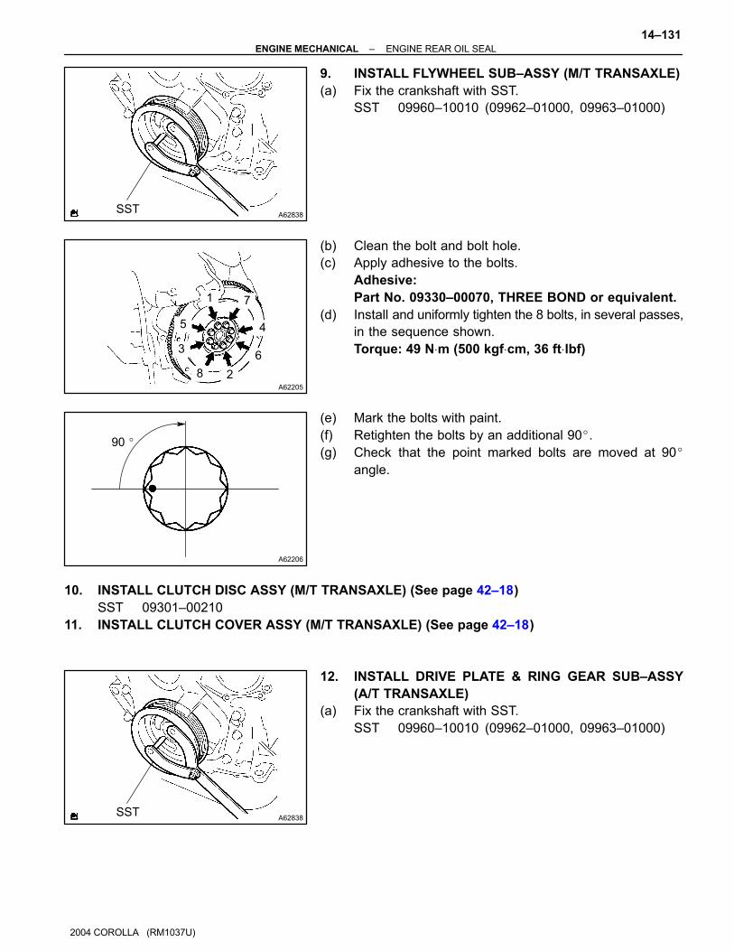
5. REMOVE FLYWHEEL SUB–ASSY (M/T TRANSAXLE)
(a) Fix the crankshaft with SST, then remove the 8 bolts and
flywheel.
SST 09960–10010 (09962–01000, 09963–01000)
6. REMOVE DRIVE PLATE & RING GEAR SUB–ASSY
(A/T TRANSAXLE)
(a) Fix the crankshaft with SST, then remove the 8 bolts and
drive plate & ring gear.
SST 09960–10010 (09962–01000, 09963–01000)
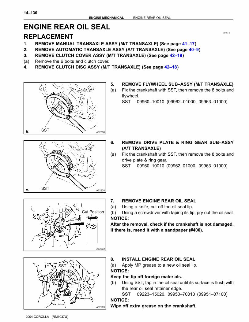
7. REMOVE ENGINE REAR OIL SEAL
(a) Using a knife, cut off the oil seal lip.
(b) Using a screwdriver with taping its tip, pry out the oil seal.
NOTICE:
After the removal, check if the crankshaft is not damaged.
If there is, mend it with a sandpaper (#400).
8. INSTALL ENGINE REAR OIL SEAL
(a) Apply MP grease to a new oil seal lip.
NOTICE:
Keep the lip off foreign materials.
(b) Using SST, tap in the oil seal until its surface is flush with
the rear oil seal retainer edge.
SST 09223–15020, 09950–70010 (09951–07100)
NOTICE:
Wipe off extra grease on the crankshaft.
A62838SST
A62205
1
5
3
8 2
6
4
7
A62206
90 �
A62838SST
–ENGINE MECHANICAL ENGINE REAR OIL SEAL
14–131
2004 COROLLA (RM1037U)
9. INSTALL FLYWHEEL SUB–ASSY (M/T TRANSAXLE)
(a) Fix the crankshaft with SST.
SST 09960–10010 (09962–01000, 09963–01000)
(b) Clean the bolt and bolt hole.
(c) Apply adhesive to the bolts.
Adhesive:
Part No. 09330–00070, THREE BOND or equivalent.
(d) Install and uniformly tighten the 8 bolts, in several passes,
in the sequence shown.
Torque: 49 N⋅m (500 kgf⋅cm, 36 ft⋅lbf)
(e) Mark the bolts with paint.
(f) Retighten the bolts by an additional 90�.
(g) Check that the point marked bolts are moved at 90�
angle.
10. INSTALL CLUTCH DISC ASSY (M/T TRANSAXLE) (See page 42–18)
SST 09301–00210
11. INSTALL CLUTCH COVER ASSY (M/T TRANSAXLE) (See page 42–18)
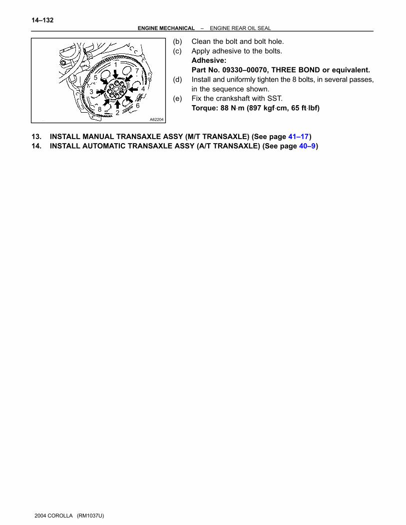
12. INSTALL DRIVE PLATE & RING GEAR SUB–ASSY
(A/T TRANSAXLE)
(a) Fix the crankshaft with SST.
SST 09960–10010 (09962–01000, 09963–01000)
A62204
1
5
3
82
6
4
7
14–132–ENGINE MECHANICAL ENGINE REAR OIL SEAL
1142
2004 COROLLA (RM1037U)
(b) Clean the bolt and bolt hole.
(c) Apply adhesive to the bolts.
Adhesive:
Part No. 09330–00070, THREE BOND or equivalent.
(d) Install and uniformly tighten the 8 bolts, in several passes,
in the sequence shown.
(e) Fix the crankshaft with SST.
Torque: 88 N⋅m (897 kgf⋅cm, 65 ft⋅lbf)
13. INSTALL MANUAL TRANSAXLE ASSY (M/T TRANSAXLE) (See page 41–17)
14. INSTALL AUTOMATIC TRANSAXLE ASSY (A/T TRANSAXLE) (See page 40–9)

140OD–01
A60622
14–4–ENGINE MECHANICAL FAN AND GENERATOR V BELT
2004 COROLLA (RM1037U)
FAN AND GENERATOR V BELT
REPLACEMENT1. REMOVE ENGINE UNDER COVER RH
2. REMOVE FAN AND GENERATOR V BELT
(a) Turn the V–ribbed belt tensioner slowly clockwise and
loosen it. Then, remove the fan and generator V belt and
put back the V–ribbed belt tensioner little by little and fix
it quietly.
140OF–03
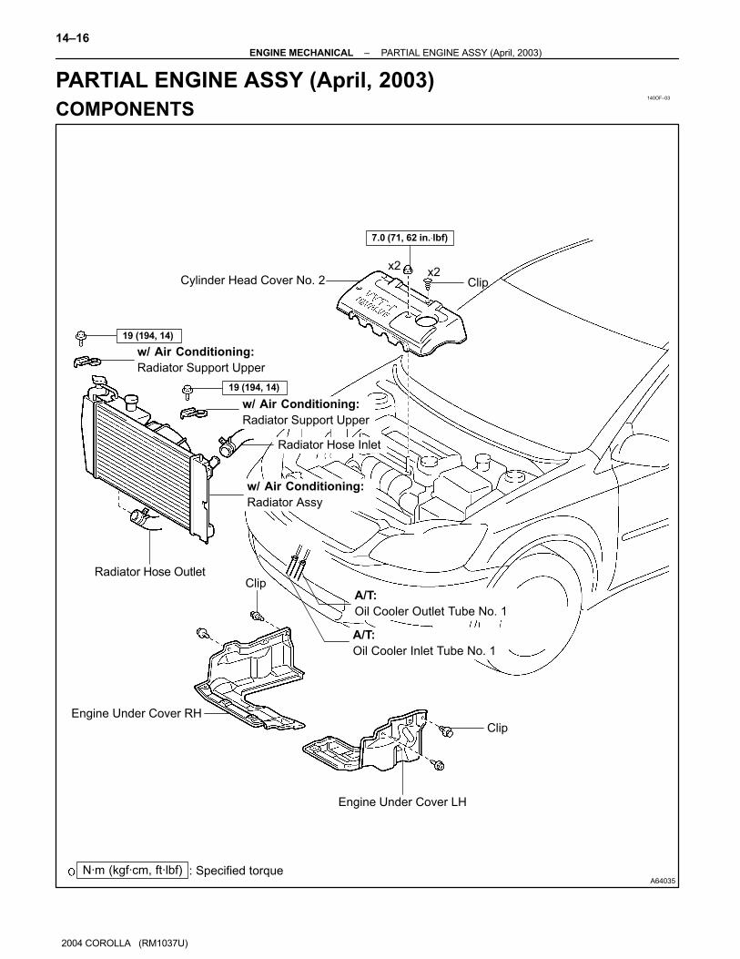
A64035
Cylinder Head Cover No. 2
w/ Air Conditioning:
Radiator Support Upper
w/ Air Conditioning:
Radiator Support Upper
Radiator Hose Inlet
Radiator Hose Outlet
w/ Air Conditioning:
Radiator Assy
Clip
19 (194, 14)
19 (194, 14)
Engine Under Cover LH
Engine Under Cover RH
Clip
Clip
N·m (kgf·cm, ft·lbf) : Specified torque
A/T:
Oil Cooler Outlet Tube No. 1
A/T:
Oil Cooler Inlet Tube No. 1
x2x2
7.0 (71, 62 in.⋅lbf)
14–16–ENGINE MECHANICAL PARTIAL ENGINE ASSY (April, 2003)
2004 COROLLA (RM1037U)
PARTIAL ENGINE ASSY (April, 2003)
COMPONENTS

A64036
Accelerator Control
Cable Assy
Heater Inlet Water Hose
EFI Fuel Pipe Clamp
Fuel Tube Sub–assy
Heater Outlet Water Hose
Union to Connector Tube Hose
Air Cleaner Cap
Sub–assy
Air Cleaner Filter
Element Sub–assy
Air Cleaner Case
Sub–assy
Battery Clamp
Sub–assy
Battery
Battery Tray
Battery Carrier
7.0 (71, 62 in.⋅lbf)
13 (133, 10)
3.5 (36, 31 in.⋅lbf)
N·m (kgf·cm, ft·lbf) : Specified torque
w/ Cruise Control:
Cruise Control Actuator Assy
6.0 (61, 53 in.⋅lbf)
5.0 (51, 44 in.⋅lbf)
–ENGINE MECHANICAL PARTIAL ENGINE ASSY (April, 2003)
14–17
2004 COROLLA (RM1037U)

A64037
Fan and Generator V Belt
w/ Air Conditioning:
Compressor and Magnetic Clutch
N·m (kgf·cm, ft·lbf) : Specified torque
29 (296, 21)
A/T:
Floor Shift Cable
Transmission Control Shift
Clip
12 (122, 9)
Return Tube Sub–assy
M/T:
Clutch Release Cylinder Assy
M/T:
Floor Shift Cable Transmission
Control Shift
M/T:
Floor Shift Cable Transmission
Control Select
Clip
Plate Washer
Clip
5.0 (51, 44 in.⋅lbf)
25 (255, 18)
7.8 (80, 69 in.⋅lbf)
12 (122, 9)
25 (255, 18)
14–18–ENGINE MECHANICAL PARTIAL ENGINE ASSY (April, 2003)
1028
2004 COROLLA (RM1037U)

A64038
Grove Compartment Door Assy
Cowl Side Trim Board RHFront Door Scuff Plate RH
Clip
Clip
Column Hole Cover Silencer Sheet
Steering Intermediate Shaft
� Cotter Pin
Tie Rod End
Sub–assy LH
Front Suspension Arm
Sub–assy Lower No. 1 LH
Front Drive Shaft Assy LH
Front Stabilizer Link Assy LH
Exhaust Pipe Assy Front
Floor Panel
Brace Front
Compression
Spring
Compression Spring
� Gasket
� Gasket
89 (908, 66)
49 (500, 36)
74 (755, 55)
35 (360, 26)
89 (908, 66)
Front Axle Hub LH Nut
� Non–reusable part
N·m (kgf·cm, ft·lbf) : Specified torque
43 (440, 32)
30 (306, 22)
43 (440, 32)
216 (2,203, 160)�
–ENGINE MECHANICAL PARTIAL ENGINE ASSY (April, 2003)
14–19
2004 COROLLA (RM1037U)

A64039N·m (kgf·cm, ft·lbf) : Specified torque
Engine Mounting
Insulator RHEngine Assembly with Transaxle
Vane Pump Assy
Front Suspension
Crossmember
w/ Center Member
80 (816, 59)
113 (1,152, 83)
157 (1,601, 116)
39 (398, 29)
52 (530, 38)
52 (530, 38)
65 (663, 48)
37 (377, 27)
52 (530, 38)
TMMC, NUMMI Made:
TAKAOKA, TAL Made:87 (887, 64)
14–20–ENGINE MECHANICAL PARTIAL ENGINE ASSY (April, 2003)
2004 COROLLA (RM1037U)
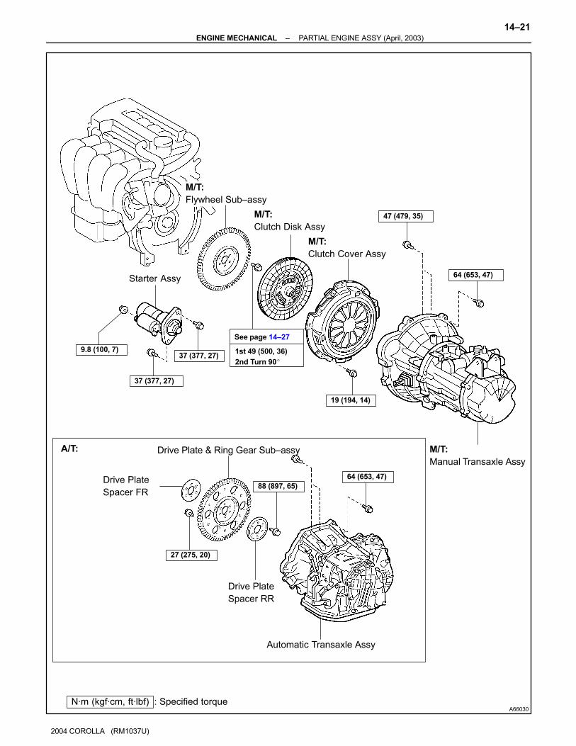
A66030N·m (kgf·cm, ft·lbf) : Specified torque
Automatic Transaxle Assy
Drive Plate
Spacer RR
Drive Plate & Ring Gear Sub–assy
Drive Plate
Spacer FR
A/T:
27 (275, 20)
88 (897, 65)
M/T:
Clutch Disk Assy
M/T:
Clutch Cover Assy
M/T:
Manual Transaxle Assy
Starter Assy
M/T:
Flywheel Sub–assy
See page 14–27
1st 49 (500, 36)
2nd Turn 90�
37 (377, 27)
37 (377, 27)
64 (653, 47)
19 (194, 14)
64 (653, 47)
9.8 (100, 7)
47 (479, 35)
–ENGINE MECHANICAL PARTIAL ENGINE ASSY (April, 2003)
14–21
2004 COROLLA (RM1037U)
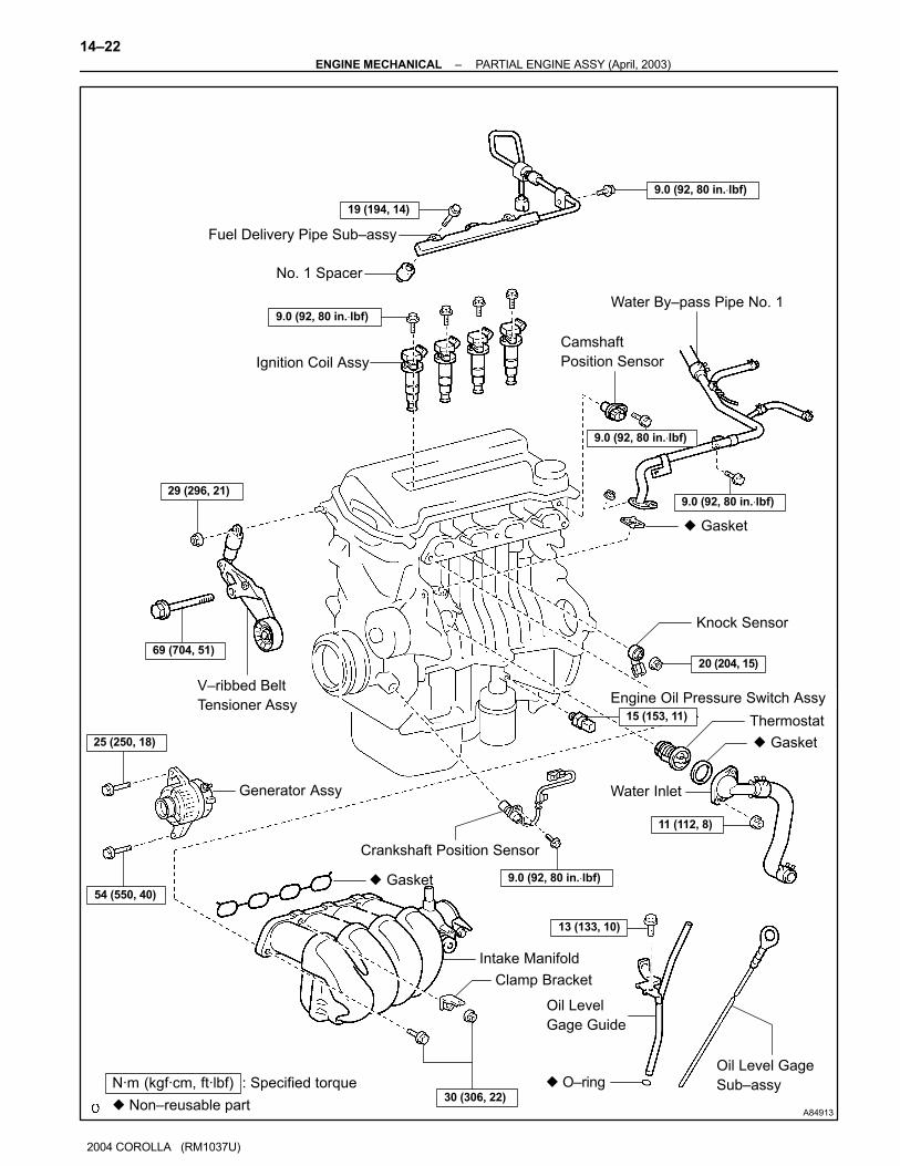
A84913
Fuel Delivery Pipe Sub–assy
No. 1 Spacer
Ignition Coil Assy
V–ribbed Belt
Tensioner Assy
� Gasket
Intake Manifold
Clamp Bracket
Oil Level
Gage Guide
� O–ringOil Level Gage
Sub–assy
Crankshaft Position Sensor
� Gasket
Thermostat
Knock Sensor
Engine Oil Pressure Switch Assy
Camshaft
Position Sensor
� Gasket
Water By–pass Pipe No. 1
� Non–reusable part
N·m (kgf·cm, ft·lbf) : Specified torque
Water Inlet
19 (194, 14)
9.0 (92, 80 in.⋅lbf)
9.0 (92, 80 in.⋅lbf)
9.0 (92, 80 in.⋅lbf)
9.0 (92, 80 in.⋅lbf)29 (296, 21)
69 (704, 51)
15 (153, 11)
20 (204, 15)
11 (112, 8)
30 (306, 22)
9.0 (92, 80 in.⋅lbf)
13 (133, 10)
25 (250, 18)
54 (550, 40)
Generator Assy
14–22–ENGINE MECHANICAL PARTIAL ENGINE ASSY (April, 2003)
2004 COROLLA (RM1037U)

A64041
Water By–pass Hose No. 2
Radiator Hose Inlet
Heater Inlet Water Hose
� Gasket
Exhaust Manifold
Manifold Stay
Exhaust Manifold Heat Insulator No. 1
� GasketEngine Coolant
Temperature Sensor
� Non–reusable part
N·m (kgf·cm, ft·lbf) : Specified torque
20 (204, 15)
9.0 (92, 80 in.⋅lbf)
37 (377, 27)
18 (184, 13)
49 (500, 36)
Clamp Bracket
10 (102, 7)
Radio Setting Condenser
–ENGINE MECHANICAL PARTIAL ENGINE ASSY (April, 2003)
14–23
2004 COROLLA (RM1037U)
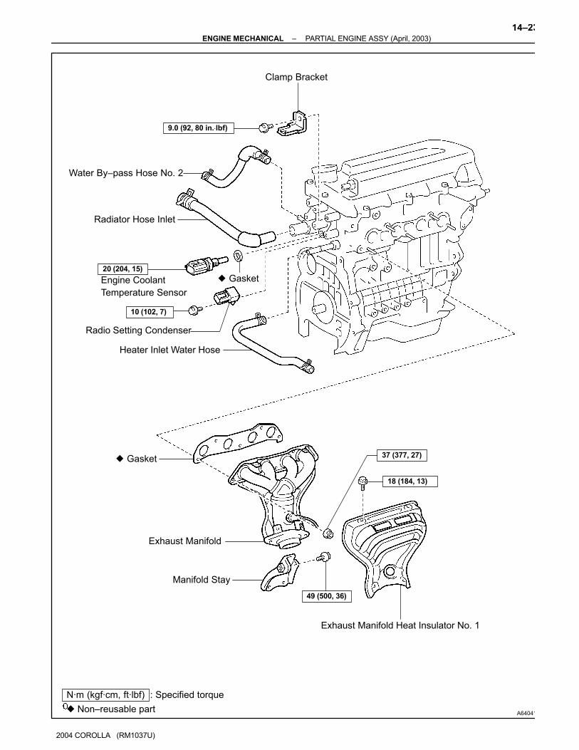
A64041
Water By–pass Hose No. 2
Radiator Hose Inlet
Heater Inlet Water Hose
� Gasket
Exhaust Manifold
Manifold Stay
Exhaust Manifold Heat Insulator No. 1
� GasketEngine Coolant
Temperature Sensor
� Non–reusable part
N·m (kgf·cm, ft·lbf) : Specified torque
20 (204, 15)
9.0 (92, 80 in.⋅lbf)
37 (377, 27)
18 (184, 13)
49 (500, 36)
Clamp Bracket
10 (102, 7)
Radio Setting Condenser
–ENGINE MECHANICAL PARTIAL ENGINE ASSY (April, 2003)
14–23
2004 COROLLA (RM1037U)

A64054
Oil Filler Cap Sub–assy
Gasket
Ventilation Valve Sub–assy
Seal Washer
Cylinder Head Cover
Sub–assy
Gasket
Spark Plug
Water Pump Assy
Crankshaft Pulley
9.0 (92, 80 in.⋅lbf)
11 (112, 8)
25 (255, 18)
� O–ring
11 (112, 8)
138 (1,407, 102)
9.0 (92, 80 in.⋅lbf)
� Non–reusable part
N·m (kgf·cm, ft·lbf) : Specified torque
Transverse Engine
Engine Mounting Bracket
47 (479, 35)
11 (112, 8)
11 (112, 8)
30 (306, 22)
14–24–ENGINE MECHANICAL PARTIAL ENGINE ASSY (April, 2003)
2004 COROLLA (RM1037U)
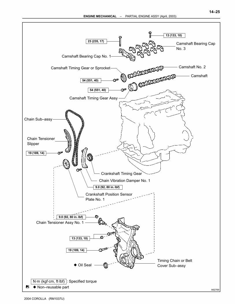
A62769
Camshaft Bearing Cap No. 1
Camshaft Timing Gear or Sprocket
Camshaft Timing Gear Assy
Camshaft Bearing Cap
No. 3
Camshaft No. 2
Camshaft
Chain Tensioner Assy No. 1
Timing Chain or Belt
Cover Sub–assy
Chain Tensioner
Slipper
Crankshaft Position Sensor
Plate No. 1
Chain Vibration Damper No. 1
Crankshaft Timing Gear
13 (133, 10)
23 (235, 17)
54 (551, 40)
54 (551, 40)
Chain Sub–assy
19 (189, 14)
9.0 (92, 80 in.⋅lbf)
9.0 (92, 80 in.⋅lbf)
13 (133, 10)
19 (189, 14)
� Oil Seal
� Non–reusable part
N·m (kgf·cm, ft·lbf) : Specified torque
–ENGINE MECHANICAL PARTIAL ENGINE ASSY (April, 2003)
14–25
2004 COROLLA (RM1037U)

A64055
Cylinder Head Sub–assy
Oil Control Valve Filter� Gasket
� Gasket
� O–ring
Camshaft Timing
Oil Control Valve Assy
Cylinder Block Sub–assy
� Oil Seal
Oil Pump Assy
� Gasket
Oil Strainer Sub–assy
Oil Filter Sub–assy� Gasket
� Gasket
1st 49 (500, 36)
2nd Turn 90�
See page 14–45
Plate Washer
30 (306, 22)9.0 (92, 80 in.⋅lbf)
9.0 (92, 80 in.⋅lbf)9.0 (92, 80 in.⋅lbf)
9.0 (92, 80 in.⋅lbf)30 (306, 22)
Oil Filter Union
37 (377, 27)
Oil Pan Drain Plug
9.0 (92, 80 in.⋅lbf)
� Non–reusable part
N·m (kgf·cm, ft·lbf) : Specified torque
Oil Pan Sub–assy
14–26–ENGINE MECHANICAL PARTIAL ENGINE ASSY (April, 2003)
2004 COROLLA (RM1037U)
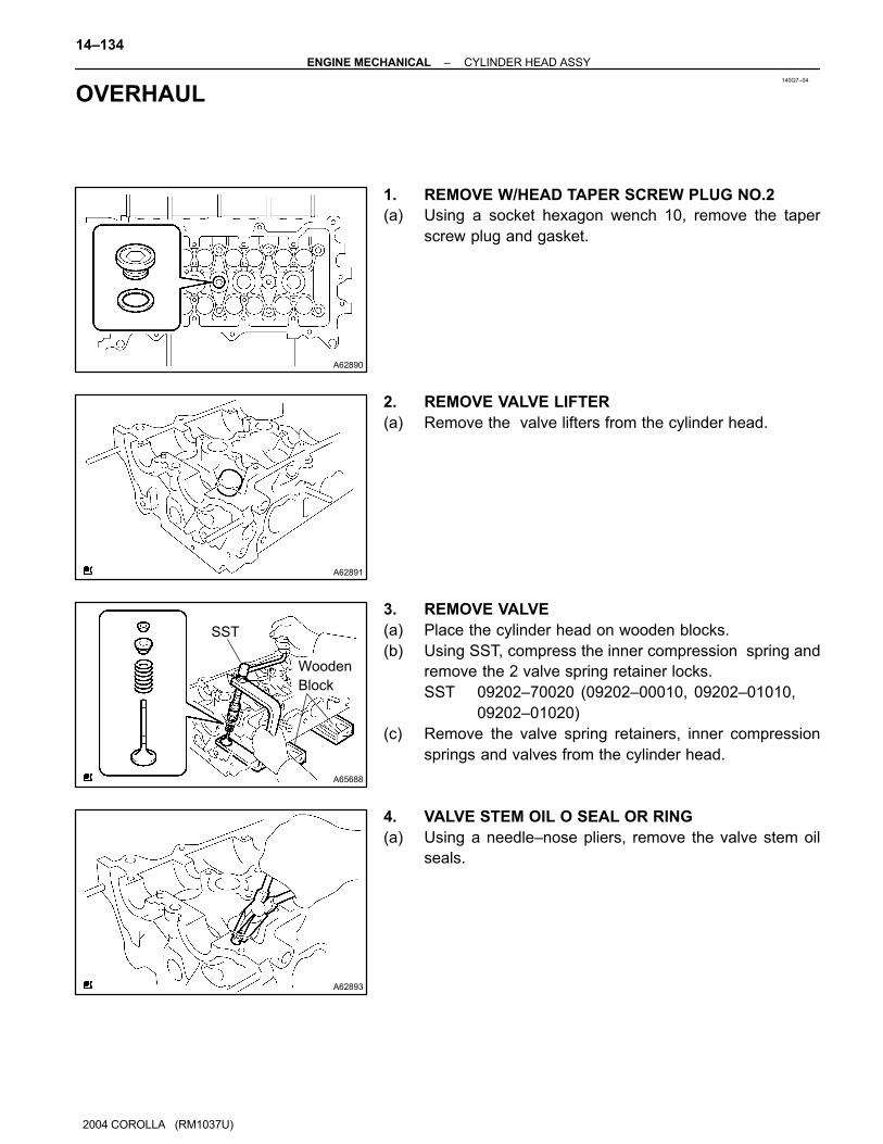
140Q7–04
A62890
A62891
A65688
SST
Wooden
Block
A62893
14–134–ENGINE MECHANICAL CYLINDER HEAD ASSY
2004 COROLLA (RM1037U)
OVERHAUL
1. REMOVE W/HEAD TAPER SCREW PLUG NO.2
(a) Using a socket hexagon wench 10, remove the taper
screw plug and gasket.
2. REMOVE VALVE LIFTER
(a) Remove the valve lifters from the cylinder head.
3. REMOVE VALVE
(a) Place the cylinder head on wooden blocks.
(b) Using SST, compress the inner compression spring and
remove the 2 valve spring retainer locks.
SST 09202–70020 (09202–00010, 09202–01010,
09202–01020)
(c) Remove the valve spring retainers, inner compression
springs and valves from the cylinder head.
4. VALVE STEM OIL O SEAL OR RING
(a) Using a needle–nose pliers, remove the valve stem oil
seals.

A62894
A65689
Front side:
Upper side:
Intake side:Exhaust side:
A65690
Cylinder block side:
Intake manifold side:
Exhaust manifold side:
–ENGINE MECHANICAL CYLINDER HEAD ASSY
14–135
2004 COROLLA (RM1037U)
5. REMOVE VALVE SPRING SEAT
(a) Using a compressed air and a magnetic finger, remove
the valve spring seats.
6. REMOVE STUD BOLT
(a) Using torx socket wrench E5 and E7, remove the 11 stud bolts.
7. INSPECT CYLINDER HEAD FOR FLATNESS
(a) Using a precision straight edge and a feeler gauge, mea-
sure the surface contacting the cylinder block and the
manifolds for warpage.
Maximum warpage:
Cylinder block side 0.05 mm (0.0020 in.)
Intake manifold side 0.10 mm (0.0039 in.)
Exhaust manifold side 0.10 mm (0.0039 in.)
If the warpage is greater than maximum, replace the cylinder
head.
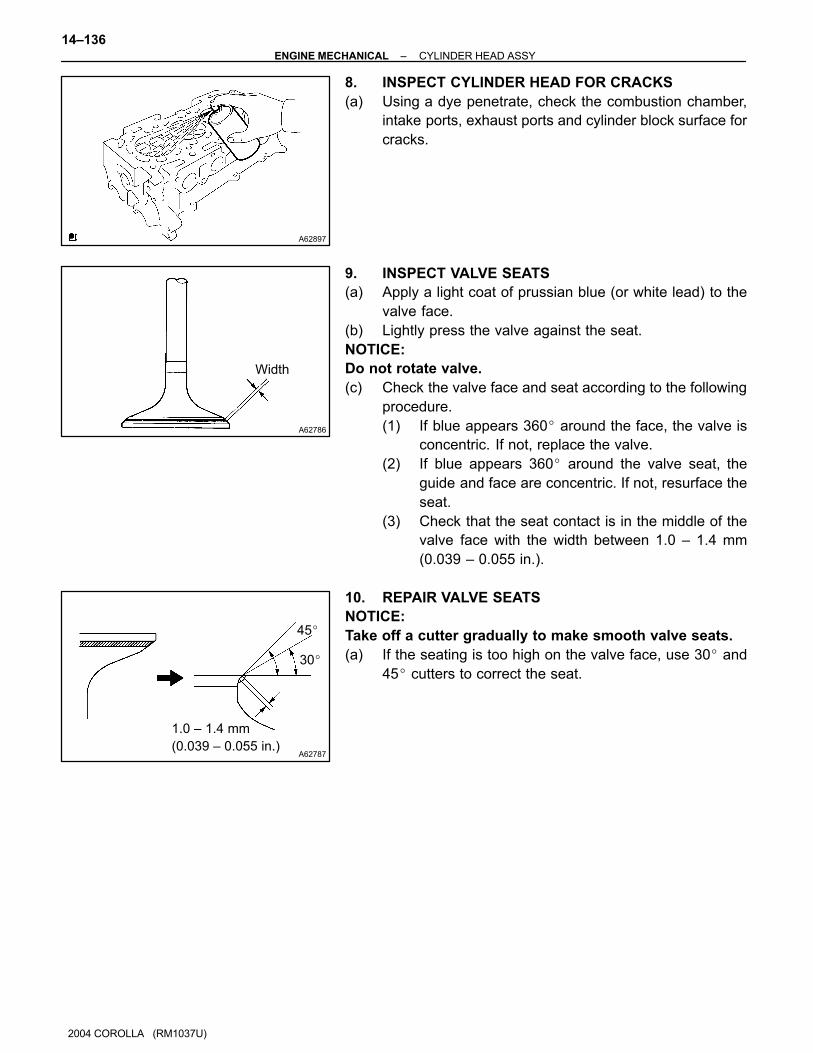
A62897
A62786
Width
A62787
1.0 – 1.4 mm
(0.039 – 0.055 in.)
30�
45�
14–136–ENGINE MECHANICAL CYLINDER HEAD ASSY
1146
2004 COROLLA (RM1037U)
8. INSPECT CYLINDER HEAD FOR CRACKS
(a) Using a dye penetrate, check the combustion chamber,
intake ports, exhaust ports and cylinder block surface for
cracks.
9. INSPECT VALVE SEATS
(a) Apply a light coat of prussian blue (or white lead) to the
valve face.
(b) Lightly press the valve against the seat.
NOTICE:
Do not rotate valve.
(c) Check the valve face and seat according to the following
procedure.
(1) If blue appears 360� around the face, the valve is
concentric. If not, replace the valve.
(2) If blue appears 360� around the valve seat, the
guide and face are concentric. If not, resurface the
seat.
(3) Check that the seat contact is in the middle of the
valve face with the width between 1.0 – 1.4 mm
(0.039 – 0.055 in.).
10. REPAIR VALVE SEATS
NOTICE:
Take off a cutter gradually to make smooth valve seats.
(a) If the seating is too high on the valve face, use 30� and
45� cutters to correct the seat.
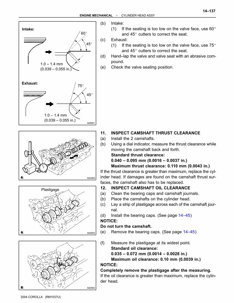
A65691
1.0 – 1.4 mm
(0.039 – 0.055 in.)
75�
45�
1.0 – 1.4 mm
(0.039 – 0.055 in.)
60�
45�
Intake:
Exhaust:
A62900
A65692
Plastigage
A62902
–ENGINE MECHANICAL CYLINDER HEAD ASSY
14–137
2004 COROLLA (RM1037U)
(b) Intake:
(1) If the seating is too low on the valve face, use 60�
and 45� cutters to correct the seat.
(c) Exhaust:
(1) If the seating is too low on the valve face, use 75�
and 45� cutters to correct the seat.
(d) Hand–lap the valve and valve seat with an abrasive com-
pound.
(e) Check the valve seating position.
11. INSPECT CAMSHAFT THRUST CLEARANCE
(a) Install the 2 camshafts.
(b) Using a dial indicator, measure the thrust clearance while
moving the camshaft back and forth.
Standard thrust clearance:
0.040 – 0.095 mm (0.0016 – 0.0037 in.)
Maximum thrust clearance: 0.110 mm (0.0043 in.)
If the thrust clearance is greater than maximum, replace the cyl-
inder head. If damages are found on the camshaft thrust sur-
faces, the camshaft also has to be replaced.
12. INSPECT CAMSHAFT OIL CLEARANCE
(a) Clean the bearing caps and camshaft journals.
(b) Place the camshafts on the cylinder head.
(c) Lay a strip of plastigage across each of the camshaft jour-
nal.
(d) Install the bearing caps. (See page 14–45)
NOTICE:
Do not turn the camshaft.
(e) Remove the bearing caps. (See page 14–45)
(f) Measure the plastigage at its widest point.
Standard oil clearance:
0.035 – 0.072 mm (0.0014 – 0.0028 in.)
Maximum oil clearance: 0.10 mm (0.0039 in.)
NOTICE:
Completely remove the plastigage after the measuring.
If the oil clearance is greater than maximum, replace the cylin-
der head.
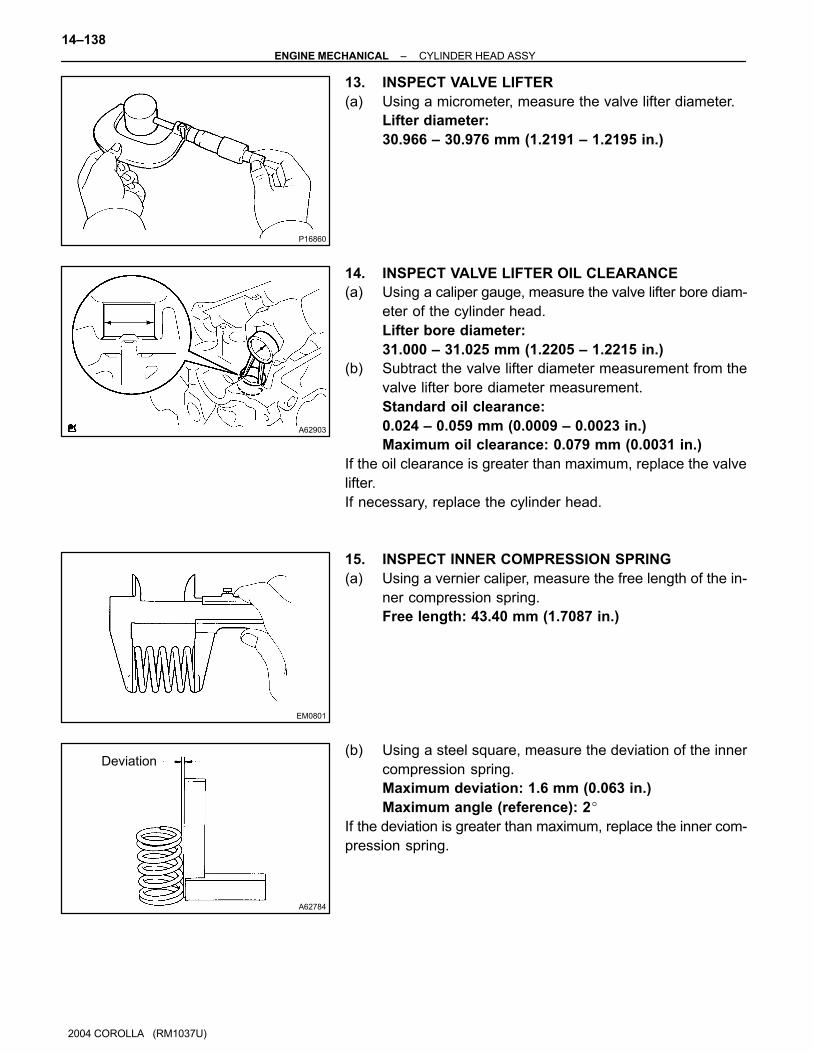
P16860
A62903
EM0801
A62784
Deviation
14–138–ENGINE MECHANICAL CYLINDER HEAD ASSY
1148
2004 COROLLA (RM1037U)
13. INSPECT VALVE LIFTER
(a) Using a micrometer, measure the valve lifter diameter.
Lifter diameter:
30.966 – 30.976 mm (1.2191 – 1.2195 in.)
14. INSPECT VALVE LIFTER OIL CLEARANCE
(a) Using a caliper gauge, measure the valve lifter bore diam-
eter of the cylinder head.
Lifter bore diameter:
31.000 – 31.025 mm (1.2205 – 1.2215 in.)
(b) Subtract the valve lifter diameter measurement from the
valve lifter bore diameter measurement.
Standard oil clearance:
0.024 – 0.059 mm (0.0009 – 0.0023 in.)
Maximum oil clearance: 0.079 mm (0.0031 in.)
If the oil clearance is greater than maximum, replace the valve
lifter.
If necessary, replace the cylinder head.
15. INSPECT INNER COMPRESSION SPRING
(a) Using a vernier caliper, measure the free length of the in-
ner compression spring.
Free length: 43.40 mm (1.7087 in.)
(b) Using a steel square, measure the deviation of the inner
compression spring.
Maximum deviation: 1.6 mm (0.063 in.)
Maximum angle (reference): 2�
If the deviation is greater than maximum, replace the inner com-
pression spring.

EM0281
EM2534
Overall
length
A62783
A62785
Margin
Thickness
A62905
–ENGINE MECHANICAL CYLINDER HEAD ASSY
14–139
2004 COROLLA (RM1037U)
(c) Using a spring tester, measure the tension of the inner
compression spring at the specified installed length.
Installed tension:
158.6 – 175.4 N (16.2 – 17.9 kgf, 35.7 – 39.5 lbf)
at 33.6 mm (1.323 in.)
Maximum working tension:
335.3 – 370.7 N (34.2 – 37.8 kgf, 75.4 – 83.3 lbf)
at 24.1 mm (0.949 in.)
If the installed tension is not as specified, replace the inner com-
pression spring.
16. INSPECT VALVE
(a) Using a vernier calipers, check the valve overall length.
Standard overall length:
Intake 88.65 mm (3.4902 in.)
Exhaust 88.69 mm (3.4917 in.)
Minimum overall length:
Intake 88.35 mm (3.4784 in.)
Exhaust 88.39 mm (3.4799 in.)
If the overall length is less than minimum, replace the valve.
(b) Using a micrometer, measure the diameter of the valve
stem.
Valve stem diameter:
Intake 5.470 – 5.485 mm (0.2154 – 0.2159 in.)
Exhaust 5.465 – 5.480 mm (0.2152 – 0.2158 in.)
(c) Using a vernier calipers, check the valve head margin
thickness.
Standard margin thickness: 1.0 mm (0.039 in.)
Minimum margin thickness: 0.7 mm (0.028 in.)
If the overall length is less than minimum, replace the valve.
17. INSPECT VALVE GUIDE BUSHING OIL CLEARANCE
(a) Using a caliper gauge, measure the inside diameter of the
valve guide bush.
Busing inside diameter:
5.510 – 5.530 mm (0.2169 – 0.2177 in.)
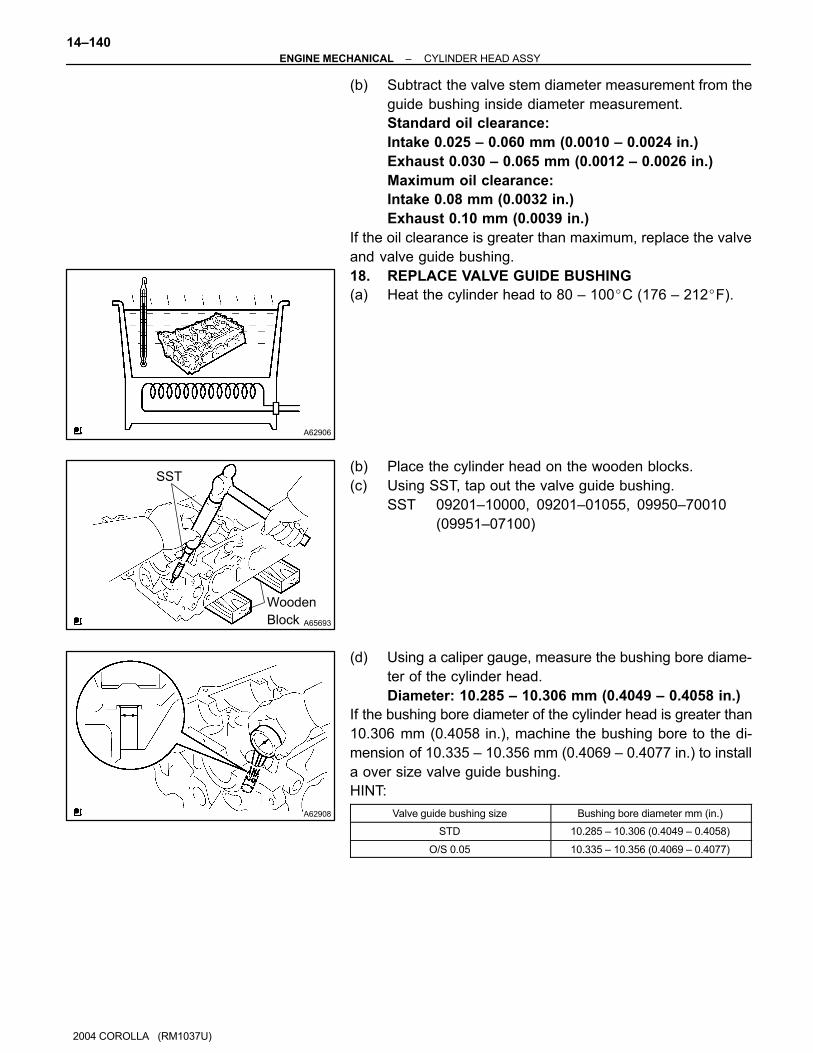
A62906
A65693
SST
Wooden
Block
A62908
14–140–ENGINE MECHANICAL CYLINDER HEAD ASSY
2004 COROLLA (RM1037U)
(b) Subtract the valve stem diameter measurement from the
guide bushing inside diameter measurement.
Standard oil clearance:
Intake 0.025 – 0.060 mm (0.0010 – 0.0024 in.)
Exhaust 0.030 – 0.065 mm (0.0012 – 0.0026 in.)
Maximum oil clearance:
Intake 0.08 mm (0.0032 in.)
Exhaust 0.10 mm (0.0039 in.)
If the oil clearance is greater than maximum, replace the valve
and valve guide bushing.
18. REPLACE VALVE GUIDE BUSHING
(a) Heat the cylinder head to 80 – 100�C (176 – 212�F).
(b) Place the cylinder head on the wooden blocks.
(c) Using SST, tap out the valve guide bushing.
SST 09201–10000, 09201–01055, 09950–70010
(09951–07100)
(d) Using a caliper gauge, measure the bushing bore diame-
ter of the cylinder head.
Diameter: 10.285 – 10.306 mm (0.4049 – 0.4058 in.)
If the bushing bore diameter of the cylinder head is greater than
10.306 mm (0.4058 in.), machine the bushing bore to the di-
mension of 10.335 – 10.356 mm (0.4069 – 0.4077 in.) to install
a over size valve guide bushing.
HINT:
Valve guide bushing size Bushing bore diameter mm (in.)
STD 10.285 – 10.306 (0.4049 – 0.4058)
O/S 0.05 10.335 – 10.356 (0.4069 – 0.4077)

A62906
A65694
SST
Wooden
Block
A65582
A65695
6
(mm (in.))
145 (0.197)
–ENGINE MECHANICAL CYLINDER HEAD ASSY
14–141
2004 COROLLA (RM1037U)
(e) Heat the cylinder head to 80 – 100�C (176 – 212�F).
(f) Place the cylinder head on wooden blocks.
(g) Using SST, tap in a new valve guide bushing to the speci-
fied protrusion height.
SST 09201–10000, 09201–01055, 09950–70010
(09951–07100)
Protrusion height: 8.7 – 9.1 mm (0.343 – 0.358 in.)
(h) Using a sharp 5.5 mm reamer, ream the valve guide bush-
ing to obtain the standard specified clearance.
Standard oil clearance:
Intake 0.025 – 0.060 mm (0.0010 – 0.0024 in.)
Exhaust 0.030 – 0.065 mm (0.0012 – 0.0026 in.)
19. INSTALL STRAIGHT PIN
(a) Using a plastic hammer, install the new 2 straight pins.
Standard protrusion: 5 mm (0.197 in.)
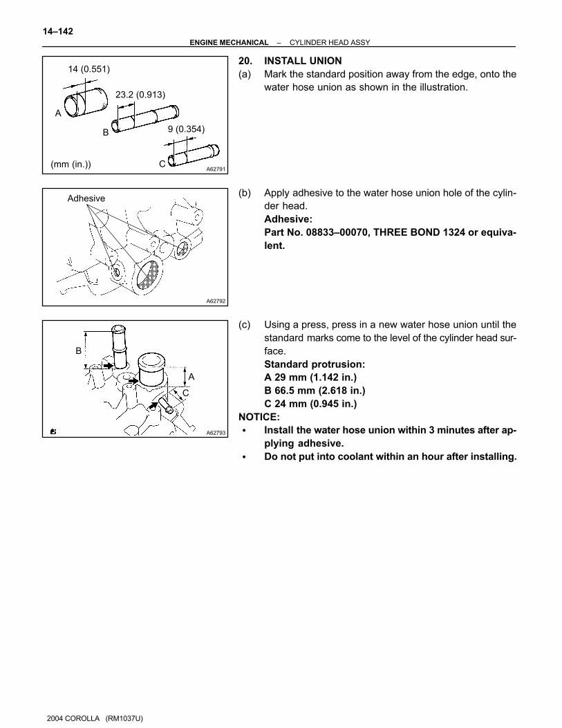
A62791
14 (0.551)
23.2 (0.913)
9 (0.354)
A
B
C(mm (in.))
A62792
Adhesive
A62793
B
A
C
14–142–ENGINE MECHANICAL CYLINDER HEAD ASSY
2004 COROLLA (RM1037U)
20. INSTALL UNION
(a) Mark the standard position away from the edge, onto the
water hose union as shown in the illustration.
(b) Apply adhesive to the water hose union hole of the cylin-
der head.
Adhesive:
Part No. 08833–00070, THREE BOND 1324 or equiva-
lent.
(c) Using a press, press in a new water hose union until the
standard marks come to the level of the cylinder head sur-
face.
Standard protrusion:
A 29 mm (1.142 in.)
B 66.5 mm (2.618 in.)
C 24 mm (0.945 in.)
NOTICE:
� Install the water hose union within 3 minutes after ap-
plying adhesive.
� Do not put into coolant within an hour after installing.
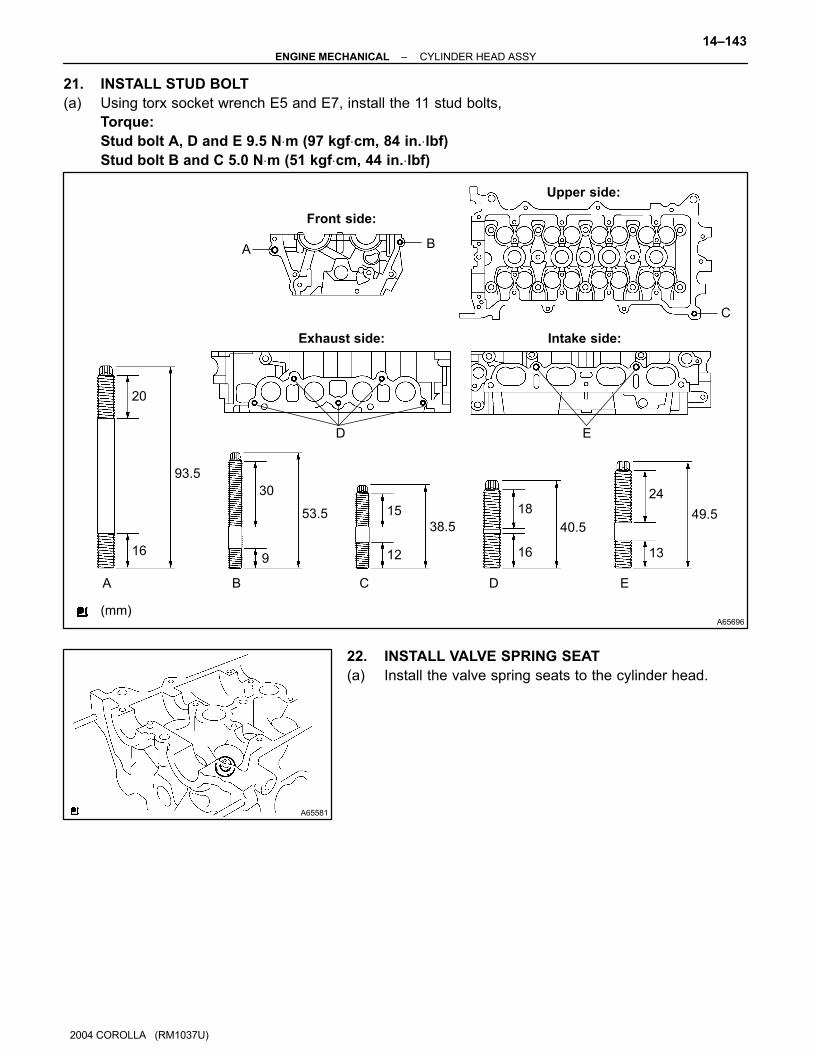
A65696
Front side:
Exhaust side: Intake side:
Upper side:
A B
D E
C
A B C D E
(mm)
20
16
93.5
30
9
53.5 15
12
38.5
18
16
40.5
24
49.5
13
A65581
–ENGINE MECHANICAL CYLINDER HEAD ASSY
14–143
2004 COROLLA (RM1037U)
21. INSTALL STUD BOLT
(a) Using torx socket wrench E5 and E7, install the 11 stud bolts,
Torque:
Stud bolt A, D and E 9.5 N⋅m (97 kgf⋅cm, 84 in.⋅lbf)
Stud bolt B and C 5.0 N⋅m (51 kgf⋅cm, 44 in.⋅lbf)
22. INSTALL VALVE SPRING SEAT
(a) Install the valve spring seats to the cylinder head.

A65697
SST
Exhaust:Intake:
Gray Surface Black Surface
A65688
SST
Wooden
Block
A65698
Pin Punch 5
A62891
14–144–ENGINE MECHANICAL CYLINDER HEAD ASSY
2004 COROLLA (RM1037U)
23. INSTALL VALVE STEM OIL O SEAL OR RING
(a) Apply a light coat of engine oil to a new valve stem oil
seals.
NOTICE:
Be very careful to assemble the oil seal for intake and ex-
haust. Assembling the wrong one may cause a failure.
HINT:
The intake valve stem oil seal is gray and exhaust valve stem
oil seal is black.
(b) Using SST, push in the valve stem oil seals.
SST 09201–41020
24. INSTALL VALVE
(a) Place the cylinder head on wooden blocks.
(b) Install the valves, inner compression springs and valve
spring retainers to the cylinder head.
(c) Using SST, compress the inner compression spring, and
place the 2 valve spring retainer locks around the valve
stem.
SST 09202–70020 (09202–00010, 09202–01010,
09202–01020)
(d) Using a pin punch 5, lightly tap the valve stem tip to en-
sure a proper fit.
NOTICE:
Be careful not to damage the valve stem tip.
25. INSTALL VALVE LIFTER
(a) Apply a light coat of engine oil to the valve lifters.
(b) Install the valve lifters to the cylinder head.
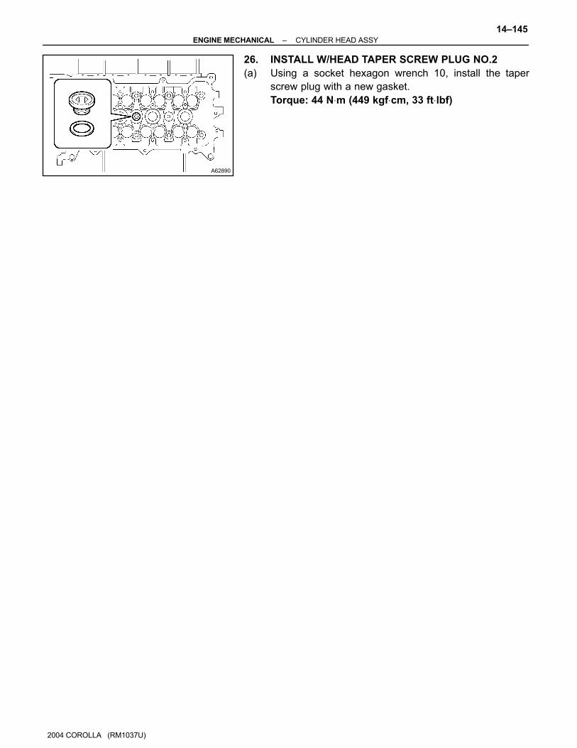
A62890
–ENGINE MECHANICAL CYLINDER HEAD ASSY
14–145
2004 COROLLA (RM1037U)
26. INSTALL W/HEAD TAPER SCREW PLUG NO.2
(a) Using a socket hexagon wrench 10, install the taper
screw plug with a new gasket.
Torque: 44 N⋅m (449 kgf⋅cm, 33 ft⋅lbf)

141GS–01
A65077
C80159
–ENGINE MECHANICAL PARTIAL ENGINE ASSY (April, 2003)
14–27
1037
2004 COROLLA (RM1037U)
REPLACEMENT1. WORK FOR PREVENTING GASOLINE FROM SPILLING OUT (See page 11–1)
2. REMOVE FRONT WHEELS
3. REMOVE ENGINE UNDER COVER RH
4. REMOVE ENGINE UNDER COVER LH
5. DRAIN COOLANT (See page 16–7)
6. REMOVE CYLINDER HEAD COVER NO.2
(a) Remove the 2 nuts, 2 clips and cylinder head cover.
7. DISCONNECT RADIATOR HOSE INLET
(a) Disconnect the radiator hose inlet from the radiator.
8. DISCONNECT RADIATOR HOSE OUTLET
(a) Disconnect the radiator hose outlet from the radiator.
9. DISCONNECT OIL COOLER INLET TUBE NO.1 (A/T TRANSAXLE)
(a) Disconnect the oil cooler inlet tube from the radiator.
10. DISCONNECT OIL COOLER OUTLET TUBE NO.1 (A/T TRANSAXLE)
(a) Disconnect the oil cooler outlet tube from the radiator.
11. REMOVE RADIATOR SUPPORT UPPER (W/ AIR CONDITIONING)
(a) Remove the 2 bolts and 2 radiator support upper.
12. REMOVE RADIATOR ASSY (W/ AIR CONDITIONING)
(a) Disconnect the connector and harness clamp, and remove the radiator.
13. REMOVE BATTERY
14. REMOVE BATTERY CARRIER
(a) Remove the 4 bolts and battery carrier.
15. REMOVE AIR CLEANER ASSEMBLY WITH HOSE
(a) Disconnect the mass air flow sensor connector.
(b) Disconnect the VSV connector.

A65177
A66032
A65807
A65832
14–28–ENGINE MECHANICAL PARTIAL ENGINE ASSY (April, 2003)
2004 COROLLA (RM1037U)
(c) Disconnect the 3 vacuum hoses, as shown in the illustra-
tion.
(d) Loosen the air cleaner hose clamp and disconnect the air
cleaner hose.
(e) Remove the air cleaner cap.
(f) Remove the air cleaner filter element.
(g) Disconnect the wire harness clamp, connector and hose.
(h) Remove the 3 bolts and air cleaner case.
16. REMOVE EFI FUEL PIPE CLAMP (See page 11–10)
17. DISCONNECT FUEL TUBE SUB–ASSY (See page 11–10)
18. SEPARATE ACCELERATOR CONTROL CABLE ASSY
(a) Loosen the nut, then remove the accelerator control cable.
19. SEPARATE CRUISE CONTROL ACTUATOR ASSY (W/
CRUISE CONTROL)
(a) Disconnect the actuator connector.
(b) Remove the 2 bolts, then separate the actuator from the
body.
20. DISCONNECT UNION TO CONNECTOR TUBE HOSE
(a) Disconnect the union to connector tube hose from the brake booster.
21. DISCONNECT HEATER INLET WATER HOSE
(a) Disconnect the heater inlet water hose from the air condi-
tioner tube.

A65833
A66034
A60622
–ENGINE MECHANICAL PARTIAL ENGINE ASSY (April, 2003)
14–29
2004 COROLLA (RM1037U)
22. DISCONNECT HEATER OUTLET WATER HOSE
(a) Disconnect the heater outlet water hose from the air con-
ditioner tube.
23. SEPARATE FLOOR SHIFT CABLE TRANSMISSION CONTROL SELECT (M/T TRANSAXLE)
(See page 41–17)
24. SEPARATE FLOOR SHIFT CABLE TRANSMISSION CONTROL SHIFT (M/T TRANSAXLE)
(See page 41–17)
25. SEPARATE FLOOR SHIFT CABLE TRANSMISSION CONTROL SHIFT (A/T TRANSAXLE)
(See page 40–9)
26. SEPARATE CLUTCH RELEASE CYLINDER ASSY (M/T TRANSAXLE) (See page 41–17)
27. REMOVE GLOVE COMPARTMENT DOOR ASSY (See page 71–10)
28. DISCONNECT ENGINE WIRE
(a) Disconnect the engine wire from the ECM and junction
block.
(b) Pull out the engine wire.
(c) Remove the engine room relay block cover.
(d) Disconnect the engine wire from the engine room relay
block.
29. REMOVE FAN AND GENERATOR V BELT
(a) Slowly turn the V–ribbed belt tensioner clockwise, then
remove the V belt.
30. SEPARATE COMPRESSOR AND MAGNETIC CLUTCH (W/ AIR CONDITIONING)
(See page 55–34)
HINT:
Hang up the hoses instead of detaching.
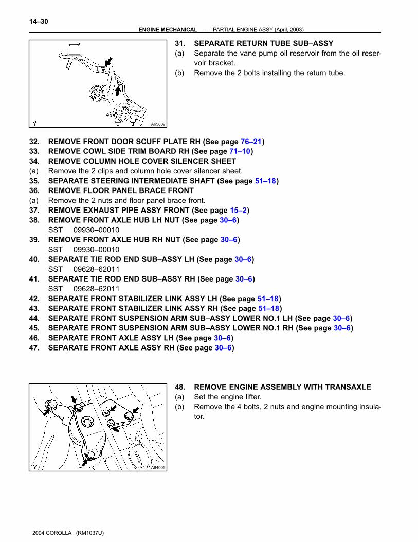
A65809
A64005
14–30–ENGINE MECHANICAL PARTIAL ENGINE ASSY (April, 2003)
2004 COROLLA (RM1037U)
31. SEPARATE RETURN TUBE SUB–ASSY
(a) Separate the vane pump oil reservoir from the oil reser-
voir bracket.
(b) Remove the 2 bolts installing the return tube.
32. REMOVE FRONT DOOR SCUFF PLATE RH (See page 76–21)
33. REMOVE COWL SIDE TRIM BOARD RH (See page 71–10)
34. REMOVE COLUMN HOLE COVER SILENCER SHEET
(a) Remove the 2 clips and column hole cover silencer sheet.
35. SEPARATE STEERING INTERMEDIATE SHAFT (See page 51–18)
36. REMOVE FLOOR PANEL BRACE FRONT
(a) Remove the 2 nuts and floor panel brace front.
37. REMOVE EXHAUST PIPE ASSY FRONT (See page 15–2)
38. REMOVE FRONT AXLE HUB LH NUT (See page 30–6)
SST 09930–00010
39. REMOVE FRONT AXLE HUB RH NUT (See page 30–6)
SST 09930–00010
40. SEPARATE TIE ROD END SUB–ASSY LH (See page 30–6)
SST 09628–62011
41. SEPARATE TIE ROD END SUB–ASSY RH (See page 30–6)
SST 09628–62011
42. SEPARATE FRONT STABILIZER LINK ASSY LH (See page 51–18)
43. SEPARATE FRONT STABILIZER LINK ASSY RH (See page 51–18)
44. SEPARATE FRONT SUSPENSION ARM SUB–ASSY LOWER NO.1 LH (See page 30–6)
45. SEPARATE FRONT SUSPENSION ARM SUB–ASSY LOWER NO.1 RH (See page 30–6)
46. SEPARATE FRONT AXLE ASSY LH (See page 30–6)
47. SEPARATE FRONT AXLE ASSY RH (See page 30–6)
48. REMOVE ENGINE ASSEMBLY WITH TRANSAXLE
(a) Set the engine lifter.
(b) Remove the 4 bolts, 2 nuts and engine mounting insula-
tor.

A55685
A50289
A62830
Front Side: Rear Side:
A62711
–ENGINE MECHANICAL PARTIAL ENGINE ASSY (April, 2003)
14–31
2004 COROLLA (RM1037U)
(c) Remove the through bolt and nut, then detach the engine
mounting insulator from the vehicle.
(d) Remove the 6 bolts, as shown in the illustration.
(e) Carefully, remove the engine with transaxle from the ve-
hicle.
(f) Install the 2 engine hangers with the 2 bolts.
Part No.:
12281–15040 for No. 1 engine hanger
12281–22021 for No. 2 engine hanger
91512–B1016 for bolt
Torque: 38 N⋅m (387 kgf⋅cm, 28 ft⋅lbf)
HINT:
Be sure to install the engine hanger (12281–22021) to the front
side of the engine and the engine hanger (12281–15040) to the
rear side.
(g) Using the chain block and engine sling device, hang the
engine assembly.
49. SEPARATE VANE PUMP ASSY (See page 51–8)
NOTICE:
Do not disconnect the hose.
50. REMOVE FRONT SUSPENSION CROSSMEMBER
W/CENTER MEMBER
(a) Remove the through bolt and nut, then detach the engine
mounting insulator FR from the engine mounting bracket.

A61180
A62838SST
A62838SST
A64021
14–32–ENGINE MECHANICAL PARTIAL ENGINE ASSY (April, 2003)
1042
2004 COROLLA (RM1037U)
(b) Remove the through bolt, then detach the engine mount-
ing insulator RR from the suspension crossmember.
(c) Separate the engine and transaxle assembly from the
suspension crossmember and engine mounting member.
51. REMOVE STARTER ASSY (See page 19–4)
52. REMOVE MANUAL TRANSAXLE ASSY (M/T TRANSAXLE) (See page 41–17)
53. REMOVE AUTOMATIC TRANSAXLE ASSY (A/T TRANSAXLE) (See page 40–9)
54. REMOVE CLUTCH COVER ASSY (M/T TRANSAXLE) (See page 42–18)
55. REMOVE CLUTCH DISC ASSY (M/T TRANSAXLE) (See page 42–18)
56. REMOVE FLYWHEEL SUB–ASSY (M/T TRANSAXLE)
(a) Fix the crankshaft with SST, then remove the 8 bolts and
flywheel.
SST 09960–10010 (09962–01000, 09963–01000)
57. REMOVE DRIVE PLATE & RING GEAR SUB–ASSY
(A/T TRANSAXLE)
(a) Fix the crankshaft with SST, then remove the 8 bolts and
drive plate & ring gear.
SST 09960–10010 (09962–01000, 09963–01000)
58. REMOVE GENERATOR ASSY (See page 19–16)
59. REMOVE IGNITION COIL ASSY
(a) Disconnect the 4 ignition coil connectors.
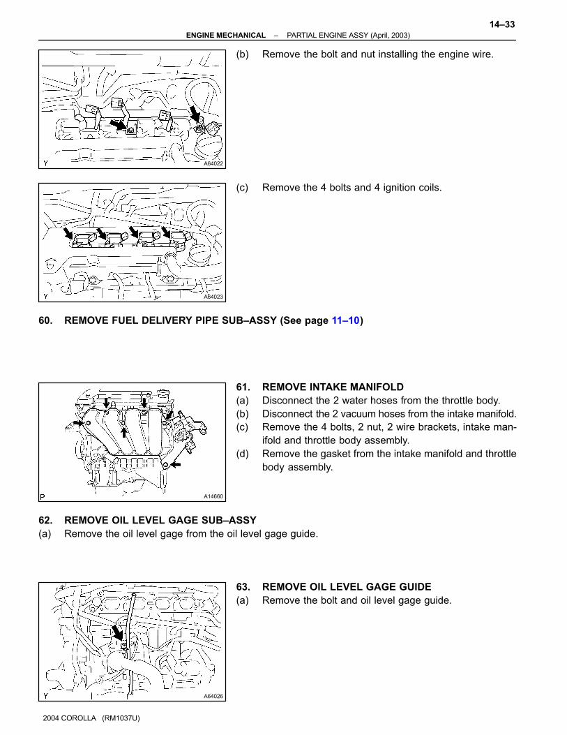
A64022
A64023
A14660
A64026
–ENGINE MECHANICAL PARTIAL ENGINE ASSY (April, 2003)
14–33
1043
2004 COROLLA (RM1037U)
(b) Remove the bolt and nut installing the engine wire.
(c) Remove the 4 bolts and 4 ignition coils.
60. REMOVE FUEL DELIVERY PIPE SUB–ASSY (See page 11–10)
61. REMOVE INTAKE MANIFOLD
(a) Disconnect the 2 water hoses from the throttle body.
(b) Disconnect the 2 vacuum hoses from the intake manifold.
(c) Remove the 4 bolts, 2 nut, 2 wire brackets, intake man-
ifold and throttle body assembly.
(d) Remove the gasket from the intake manifold and throttle
body assembly.
62. REMOVE OIL LEVEL GAGE SUB–ASSY
(a) Remove the oil level gage from the oil level gage guide.
63. REMOVE OIL LEVEL GAGE GUIDE
(a) Remove the bolt and oil level gage guide.
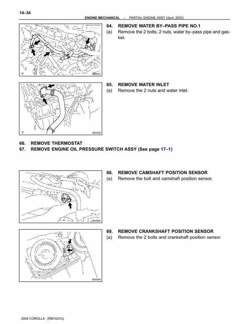
A64027
A64028
B00084
B00086
14–34–ENGINE MECHANICAL PARTIAL ENGINE ASSY (April, 2003)
2004 COROLLA (RM1037U)
64. REMOVE WATER BY–PASS PIPE NO.1
(a) Remove the 2 bolts, 2 nuts, water by–pass pipe and gas-
ket.
65. REMOVE WATER INLET
(a) Remove the 2 nuts and water inlet.
66. REMOVE THERMOSTAT
67. REMOVE ENGINE OIL PRESSURE SWITCH ASSY (See page 17–1)
68. REMOVE CAMSHAFT POSITION SENSOR
(a) Remove the bolt and camshaft position sensor.
69. REMOVE CRANKSHAFT POSITION SENSOR
(a) Remove the 2 bolts and crankshaft position sensor.
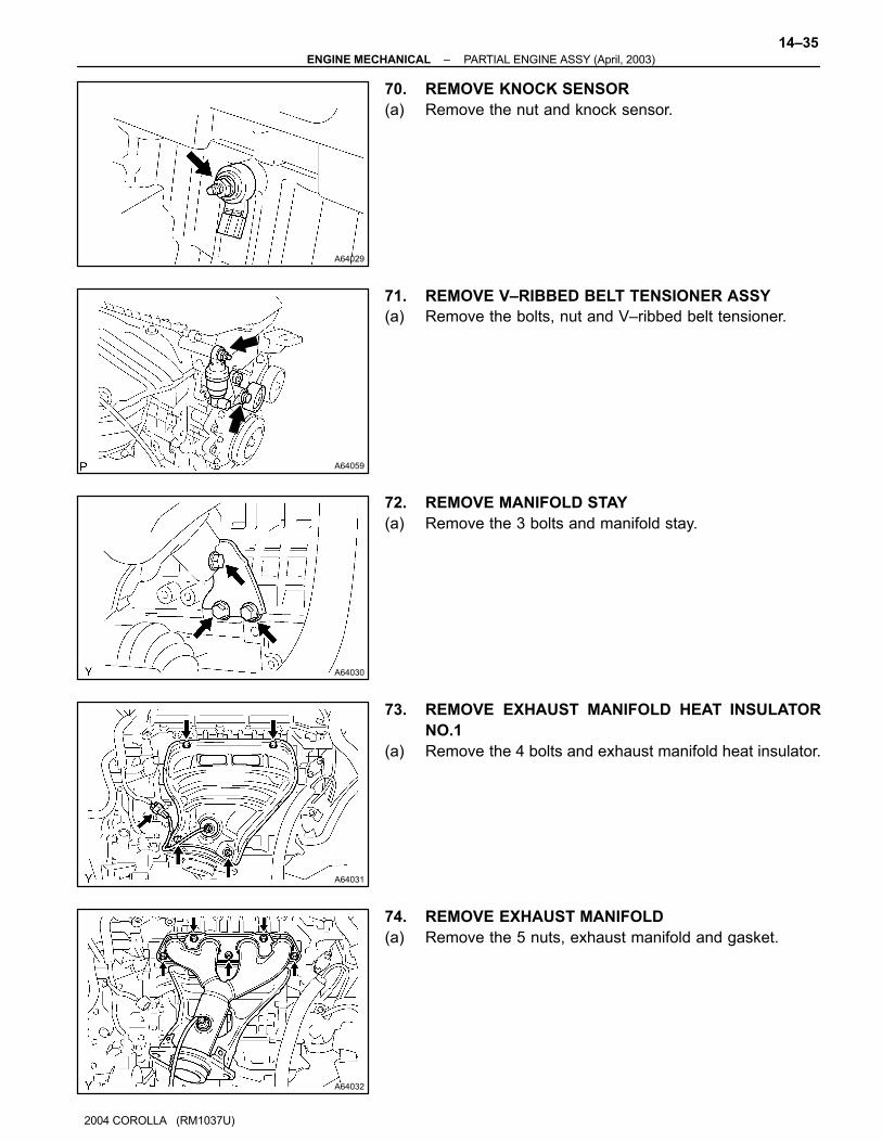
A64029
A64059
A64030
A64031
A64032
–ENGINE MECHANICAL PARTIAL ENGINE ASSY (April, 2003)
14–35
2004 COROLLA (RM1037U)
70. REMOVE KNOCK SENSOR
(a) Remove the nut and knock sensor.
71. REMOVE V–RIBBED BELT TENSIONER ASSY
(a) Remove the bolts, nut and V–ribbed belt tensioner.
72. REMOVE MANIFOLD STAY
(a) Remove the 3 bolts and manifold stay.
73. REMOVE EXHAUST MANIFOLD HEAT INSULATOR
NO.1
(a) Remove the 4 bolts and exhaust manifold heat insulator.
74. REMOVE EXHAUST MANIFOLD
(a) Remove the 5 nuts, exhaust manifold and gasket.

A64033
A64034
A64034
A64033
14–36–ENGINE MECHANICAL PARTIAL ENGINE ASSY (April, 2003)
2004 COROLLA (RM1037U)
75. REMOVE ENGINE COOLANT TEMPERATURE
SENSOR
(a) Using SST, remove the engine coolant temperature sen-
sor.
SST 09817–33190
76. REMOVE RADIO SETTING CONDENSER
(a) Remove the bolt and condenser.
77. REMOVE WATER BY–PASS HOSE NO.2
78. REMOVE RADIATOR HOSE INLET
79. REMOVE HEATER INLET WATER HOSE
80. REPLACE PARTIAL ENGINE ASSY
81. INSTALL RADIO SETTING CONDENSER
(a) Install the condenser with the bolt.
Torque: 10 N⋅m (102 kgf⋅cm, 7 ft⋅lbf)
82. INSTALL ENGINE COOLANT TEMPERATURE
SENSOR
(a) Install a new gasket to the engine coolant temperature
sensor.
(b) Using SST, install the engine coolant temperature sensor.
SST 09817–33190
Torque: 20 N⋅m (204 kgf⋅cm, 15 ft⋅lbf)
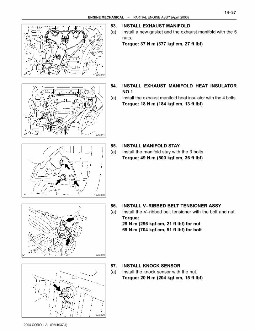
A64032
A64031
A64030
A64059
A64029
–ENGINE MECHANICAL PARTIAL ENGINE ASSY (April, 2003)
14–37
2004 COROLLA (RM1037U)
83. INSTALL EXHAUST MANIFOLD
(a) Install a new gasket and the exhaust manifold with the 5
nuts.
Torque: 37 N⋅m (377 kgf⋅cm, 27 ft⋅lbf)
84. INSTALL EXHAUST MANIFOLD HEAT INSULATOR
NO.1
(a) Install the exhaust manifold heat insulator with the 4 bolts.
Torque: 18 N⋅m (184 kgf⋅cm, 13 ft⋅lbf)
85. INSTALL MANIFOLD STAY
(a) Install the manifold stay with the 3 bolts.
Torque: 49 N⋅m (500 kgf⋅cm, 36 ft⋅lbf)
86. INSTALL V–RIBBED BELT TENSIONER ASSY
(a) Install the V–ribbed belt tensioner with the bolt and nut.
Torque:
29 N⋅m (296 kgf⋅cm, 21 ft⋅lbf) for nut
69 N⋅m (704 kgf⋅cm, 51 ft⋅lbf) for bolt
87. INSTALL KNOCK SENSOR
(a) Install the knock sensor with the nut.
Torque: 20 N⋅m (204 kgf⋅cm, 15 ft⋅lbf)
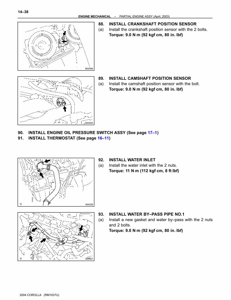
B00086
B00084
A64028
A64027
14–38–ENGINE MECHANICAL PARTIAL ENGINE ASSY (April, 2003)
2004 COROLLA (RM1037U)
88. INSTALL CRANKSHAFT POSITION SENSOR
(a) Install the crankshaft position sensor with the 2 bolts.
Torque: 9.0 N⋅m (92 kgf⋅cm, 80 in.⋅lbf)
89. INSTALL CAMSHAFT POSITION SENSOR
(a) Install the camshaft position sensor with the bolt.
Torque: 9.0 N⋅m (92 kgf⋅cm, 80 in.⋅lbf)
90. INSTALL ENGINE OIL PRESSURE SWITCH ASSY (See page 17–1)
91. INSTALL THERMOSTAT (See page 16–11)
92. INSTALL WATER INLET
(a) Install the water inlet with the 2 nuts.
Torque: 11 N⋅m (112 kgf⋅cm, 8 ft⋅lbf)
93. INSTALL WATER BY–PASS PIPE NO.1
(a) Install a new gasket and water by–pass with the 2 nuts
and 2 bolts.
Torque: 9.0 N⋅m (92 kgf⋅cm, 80 in.⋅lbf)
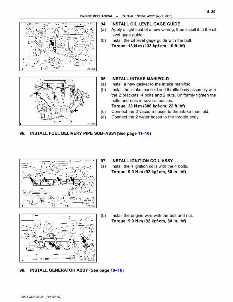
A64026
A14660
A64023
A64022
–ENGINE MECHANICAL PARTIAL ENGINE ASSY (April, 2003)
14–39
2004 COROLLA (RM1037U)
94. INSTALL OIL LEVEL GAGE GUIDE
(a) Apply a light coat of a new O–ring, then install it to the oil
level gage guide.
(b) Install the oil level gage guide with the bolt.
Torque: 13 N⋅m (133 kgf⋅cm, 10 ft⋅lbf)
95. INSTALL INTAKE MANIFOLD
(a) Install a new gasket to the intake manifold.
(b) Install the intake manifold and throttle body assembly with
the 2 brackets, 4 bolts and 2 nuts. Uniformly tighten the
bolts and nuts in several passes.
Torque: 30 N⋅m (306 kgf⋅cm, 22 ft⋅lbf)
(c) Connect the 2 vacuum hoses to the intake manifold.
(d) Connect the 2 water hoses to the throttle body.
96. INSTALL FUEL DELIVERY PIPE SUB–ASSY(See page 11–10)
97. INSTALL IGNITION COIL ASSY
(a) Install the 4 ignition coils with the 4 bolts.
Torque: 9.0 N⋅m (92 kgf⋅cm, 80 in.⋅lbf)
(b) Install the engine wire with the bolt and nut.
Torque: 9.0 N⋅m (92 kgf⋅cm, 80 in.⋅lbf)
98. INSTALL GENERATOR ASSY (See page 19–16)
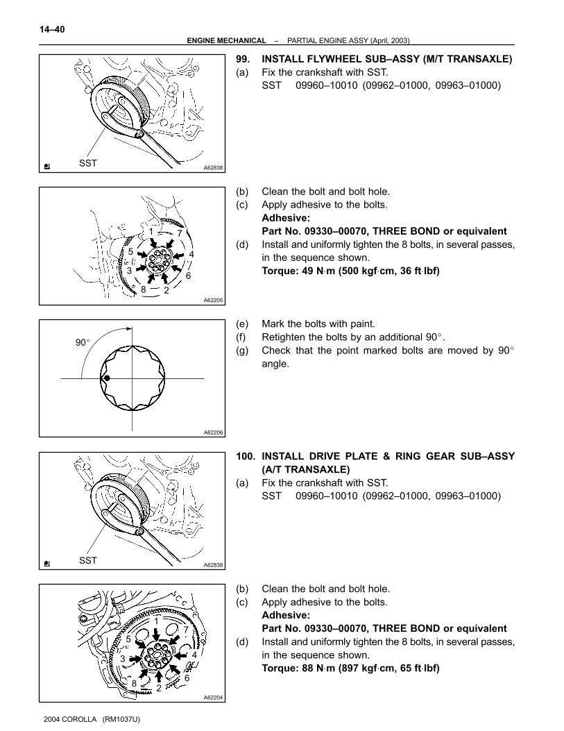
A62838SST
A62205
1
5
3
8 2
6
4
7
A62206
90�
A62838SST
A62204
1
5
3
82
6
4
7
14–40–ENGINE MECHANICAL PARTIAL ENGINE ASSY (April, 2003)
2004 COROLLA (RM1037U)
99. INSTALL FLYWHEEL SUB–ASSY (M/T TRANSAXLE)
(a) Fix the crankshaft with SST.
SST 09960–10010 (09962–01000, 09963–01000)
(b) Clean the bolt and bolt hole.
(c) Apply adhesive to the bolts.
Adhesive:
Part No. 09330–00070, THREE BOND or equivalent
(d) Install and uniformly tighten the 8 bolts, in several passes,
in the sequence shown.
Torque: 49 N⋅m (500 kgf⋅cm, 36 ft⋅lbf)
(e) Mark the bolts with paint.
(f) Retighten the bolts by an additional 90�.
(g) Check that the point marked bolts are moved by 90�
angle.
100. INSTALL DRIVE PLATE & RING GEAR SUB–ASSY
(A/T TRANSAXLE)
(a) Fix the crankshaft with SST.
SST 09960–10010 (09962–01000, 09963–01000)
(b) Clean the bolt and bolt hole.
(c) Apply adhesive to the bolts.
Adhesive:
Part No. 09330–00070, THREE BOND or equivalent
(d) Install and uniformly tighten the 8 bolts, in several passes,
in the sequence shown.
Torque: 88 N⋅m (897 kgf⋅cm, 65 ft⋅lbf)
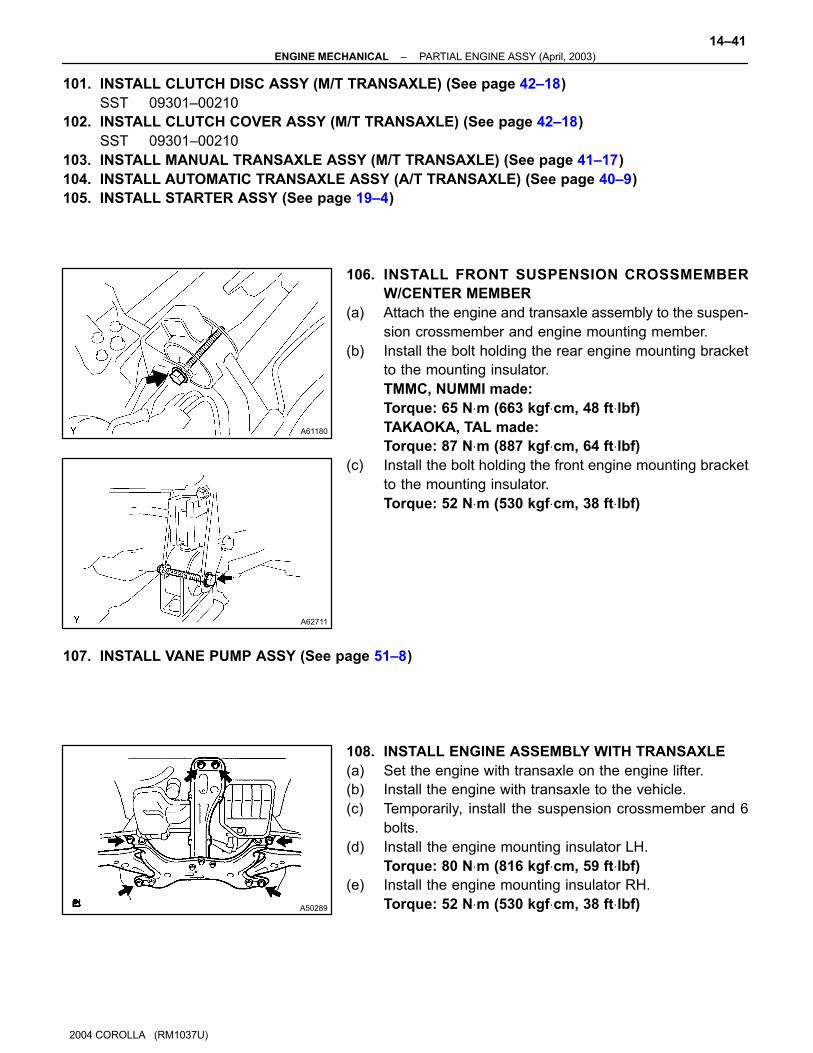
A61180
A62711
A50289
–ENGINE MECHANICAL PARTIAL ENGINE ASSY (April, 2003)
14–41
2004 COROLLA (RM1037U)
101. INSTALL CLUTCH DISC ASSY (M/T TRANSAXLE) (See page 42–18)
SST 09301–00210
102. INSTALL CLUTCH COVER ASSY (M/T TRANSAXLE) (See page 42–18)
SST 09301–00210
103. INSTALL MANUAL TRANSAXLE ASSY (M/T TRANSAXLE) (See page 41–17)
104. INSTALL AUTOMATIC TRANSAXLE ASSY (A/T TRANSAXLE) (See page 40–9)
105. INSTALL STARTER ASSY (See page 19–4)
106. INSTALL FRONT SUSPENSION CROSSMEMBER
W/CENTER MEMBER
(a) Attach the engine and transaxle assembly to the suspen-
sion crossmember and engine mounting member.
(b) Install the bolt holding the rear engine mounting bracket
to the mounting insulator.
TMMC, NUMMI made:
Torque: 65 N⋅m (663 kgf⋅cm, 48 ft⋅lbf)
TAKAOKA, TAL made:
Torque: 87 N⋅m (887 kgf⋅cm, 64 ft⋅lbf)
(c) Install the bolt holding the front engine mounting bracket
to the mounting insulator.
Torque: 52 N⋅m (530 kgf⋅cm, 38 ft⋅lbf)
107. INSTALL VANE PUMP ASSY (See page 51–8)
108. INSTALL ENGINE ASSEMBLY WITH TRANSAXLE
(a) Set the engine with transaxle on the engine lifter.
(b) Install the engine with transaxle to the vehicle.
(c) Temporarily, install the suspension crossmember and 6
bolts.
(d) Install the engine mounting insulator LH.
Torque: 80 N⋅m (816 kgf⋅cm, 59 ft⋅lbf)
(e) Install the engine mounting insulator RH.
Torque: 52 N⋅m (530 kgf⋅cm, 38 ft⋅lbf)

A62831
SST
A
B
A62832
SST
A
B
A50337
14–42–ENGINE MECHANICAL PARTIAL ENGINE ASSY (April, 2003)
2004 COROLLA (RM1037U)
(f) Insert SST to the positioning holes on the right handle
crossmember and on the right–handle of the vehicle.
SST 09670–00010
(g) Temporarily tighten the bolt A first, then bolt B.
(h) Insert SST to the positioning holes on the left handle
crossmember and on the left–handle of the vehicle.
SST 09670–00010
(i) Temporarily tighten the bolt A first, then bolt B.
(j) Insert SST to the positioning holes on the right–handle
crossmember and right–handle of the vehicle, then tight-
en the bolts with the specified torque.
(k) Insert SST to the positioning holes on the right–handle
crossmember and left–handle of the vehicle, then tighten
the bolts with the specified torque.
SST 09670–00010
Torque:
157 N⋅m (1,601 kgf⋅cm, 116 ft⋅lbf) for bolt A
113 N⋅m (1,152 kgf⋅cm, 83 ft⋅lbf) for bolt B
(l) Tighten the 2 bolts, as shown in the illustration.
Torque: 39 N⋅m (398 kgf⋅cm, 29 ft⋅lbf)
NOTICE:
After installing the crossmember, check that the position-
ing holes on the crossmember and vehicle are aligned with
each other.
109. INSTALL FRONT SUSPENSION ARM SUB–ASSY LOWER NO.1 LH (See page 30–6)
110. INSTALL FRONT SUSPENSION ARM SUB–ASSY LOWER NO.1 RH (See page 30–6)
111. INSTALL FRONT STABILIZER LINK ASSY LH (See page 51–18)
112. INSTALL FRONT STABILIZER LINK ASSY RH (See page 51–18)
113. INSTALL TIE ROD END SUB–ASSY LH (See page 30–6)
114. INSTALL TIE ROD END SUB–ASSY RH (See page 30–6)
115. INSTALL FRONT AXLE HUB LH NUT (See page 30–6)
116. INSTALL FRONT AXLE HUB RH NUT (See page 30–6)
117. INSTALL EXHAUST PIPE ASSY FRONT (See page 15–2)
118. INSTALL FLOOR PANEL BRACE FRONT
(a) Install the front floor panel brace with the 2 nuts.
Torque: 30 N⋅m (306 kgf⋅cm, 22 ft⋅lbf)
119. INSTALL STEERING INTERMEDIATE SHAFT (See page 51–18)
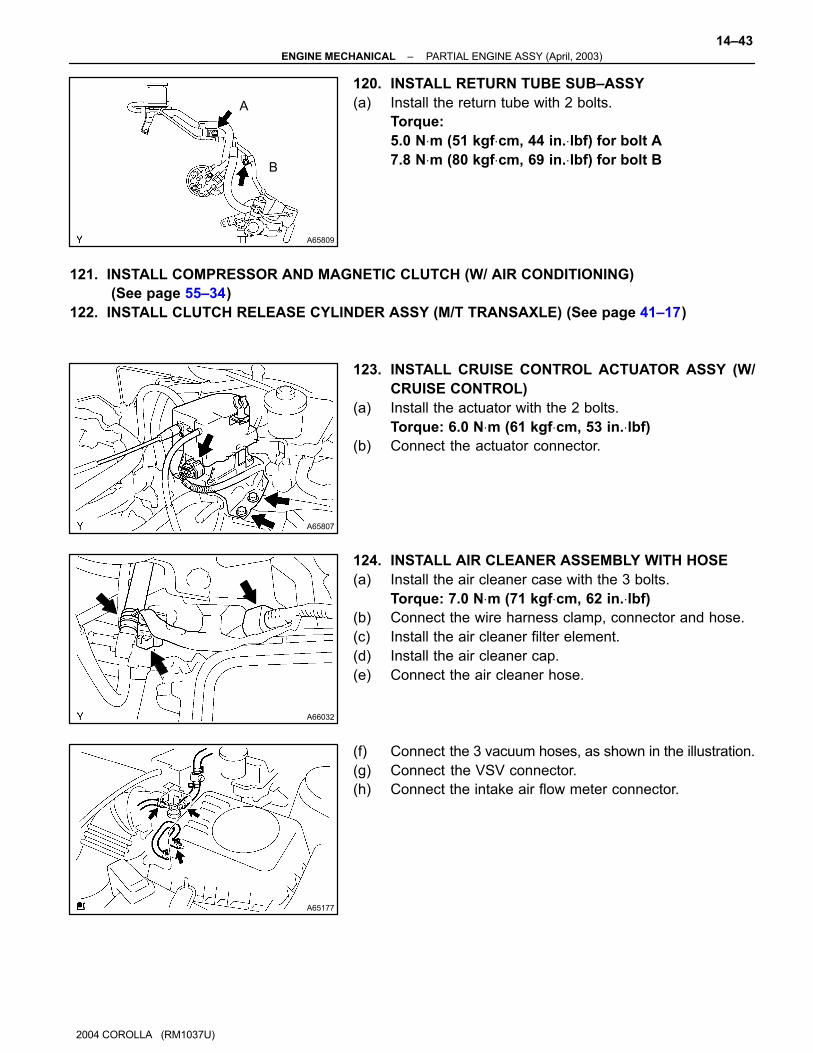
A65809
A
B
A65807
A66032
A65177
–ENGINE MECHANICAL PARTIAL ENGINE ASSY (April, 2003)
14–43
2004 COROLLA (RM1037U)
120. INSTALL RETURN TUBE SUB–ASSY
(a) Install the return tube with 2 bolts.
Torque:
5.0 N⋅m (51 kgf⋅cm, 44 in.⋅lbf) for bolt A
7.8 N⋅m (80 kgf⋅cm, 69 in.⋅lbf) for bolt B
121. INSTALL COMPRESSOR AND MAGNETIC CLUTCH (W/ AIR CONDITIONING)
(See page 55–34)
122. INSTALL CLUTCH RELEASE CYLINDER ASSY (M/T TRANSAXLE) (See page 41–17)
123. INSTALL CRUISE CONTROL ACTUATOR ASSY (W/
CRUISE CONTROL)
(a) Install the actuator with the 2 bolts.
Torque: 6.0 N⋅m (61 kgf⋅cm, 53 in.⋅lbf)
(b) Connect the actuator connector.
124. INSTALL AIR CLEANER ASSEMBLY WITH HOSE
(a) Install the air cleaner case with the 3 bolts.
Torque: 7.0 N⋅m (71 kgf⋅cm, 62 in.⋅lbf)
(b) Connect the wire harness clamp, connector and hose.
(c) Install the air cleaner filter element.
(d) Install the air cleaner cap.
(e) Connect the air cleaner hose.
(f) Connect the 3 vacuum hoses, as shown in the illustration.
(g) Connect the VSV connector.
(h) Connect the intake air flow meter connector.

C80159
A65077
14–44–ENGINE MECHANICAL PARTIAL ENGINE ASSY (April, 2003)
1054
2004 COROLLA (RM1037U)
125. INSTALL BATTERY CARRIER
(a) Install the battery carrier with the 4 bolts.
Torque: 13 N⋅m (133 kgf⋅cm, 10 ft⋅lbf)
126. INSTALL BATTERY
Torque:
5.0 N⋅m (51 kgf⋅cm, 44 in.⋅lbf) for bolt
3.5 N⋅m (36 kgf⋅cm, 31 in.⋅lbf) for nut
127. INSTALL RADIATOR SUPPORT UPPER (W/ AIR CONDITIONING)
(a) Install the 2 radiator support uppers with the 2 bolts.
Torque: 19 N⋅m (194 kgf⋅cm, 14 ft⋅lbf)
128. INSTALL CYLINDER HEAD COVER NO.2
(a) Install the cylinder head cover with the 2 nuts and 2 clips.
Torque: 7.0 N⋅m (71 kgf⋅cm, 62 in.⋅lbf)
129. INSTALL FRONT WHEELS
Torque: 103 N⋅m (1,050 kgf⋅cm, 76 ft⋅lbf)
130. ADD AUTOMATIC TRANSAXLE FLUID (A/T TRANSAXLE)
131. ADD ENGINE OIL
132. ADD COOLANT (See page 16–7)
133. CHECK FOR ENGINE OIL LEAKS
134. CHECK FOR ENGINE COOLANT LEAKS (See page 16–7)
135. CHECK FUEL LEAK
136. CHECK FOR EXHAUST GAS LEAKS
137. INSPECT CHECK IDLE SPEED AND IGNITION TIMING (See page 14–1)
SST 09843–18040
138. INSPECT CO/HC (See page 14–1)
139. INSPECT AND ADJUST FRONT WHEEL ALIGNMENT (See page 26–5)
140. CHECK ABS SPEED SENSOR SIGNAL (W/ ABS)
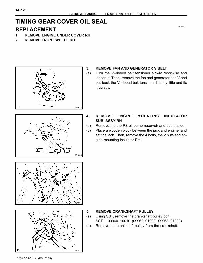
140OM–01
A60622
A01045
A64005
A62837
SST
14–128–ENGINE MECHANICAL TIMING CHAIN OR BELT COVER OIL SEAL
1138
2004 COROLLA (RM1037U)
TIMING GEAR COVER OIL SEAL
REPLACEMENT1. REMOVE ENGINE UNDER COVER RH
2. REMOVE FRONT WHEEL RH
3. REMOVE FAN AND GENERATOR V BELT
(a) Turn the V–ribbed belt tensioner slowly clockwise and
loosen it. Then, remove the fan and generator belt V and
put back the V–ribbed belt tensioner little by little and fix
it quietly.
4. REMOVE ENGINE MOUNTING INSULATOR
SUB–ASSY RH
(a) Remove the the PS oil pump reservoir and put it aside.
(b) Place a wooden block between the jack and engine, and
set the jack. Then, remove the 4 bolts, the 2 nuts and en-
gine mounting insulator RH.
5. REMOVE CRANKSHAFT PULLEY
(a) Using SST, remove the crankshaft pulley bolt.
SST 09960–10010 (09962–01000, 09963–01000)
(b) Remove the crankshaft pulley from the crankshaft.
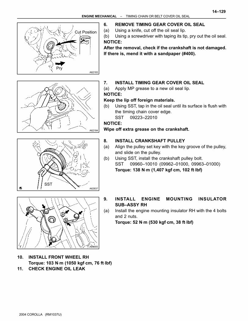
A62183
Cut Position
Pry
A62184
A62837
SST
A64005
–ENGINE MECHANICAL TIMING CHAIN OR BELT COVER OIL SEAL
14–129
2004 COROLLA (RM1037U)
6. REMOVE TIMING GEAR COVER OIL SEAL
(a) Using a knife, cut off the oil seal lip.
(b) Using a screwdriver with taping its tip, pry out the oil seal.
NOTICE:
After the removal, check if the crankshaft is not damaged.
If there is, mend it with a sandpaper (#400).
7. INSTALL TIMING GEAR COVER OIL SEAL
(a) Apply MP grease to a new oil seal lip.
NOTICE:
Keep the lip off foreign materials.
(b) Using SST, tap in the oil seal until its surface is flush with
the timing chain cover edge.
SST 09223–22010
NOTICE:
Wipe off extra grease on the crankshaft.
8. INSTALL CRANKSHAFT PULLEY
(a) Align the pulley set key with the key groove of the pulley,
and slide on the pulley.
(b) Using SST, install the crankshaft pulley bolt.
SST 09960–10010 (09962–01000, 09963–01000)
Torque: 138 N⋅m (1,407 kgf⋅cm, 102 ft⋅lbf)
9. INSTALL ENGINE MOUNTING INSULATOR
SUB–ASSY RH
(a) Install the engine mounting insulator RH with the 4 bolts
and 2 nuts.
Torque: 52 N⋅m (530 kgf⋅cm, 38 ft⋅lbf)
10. INSTALL FRONT WHEEL RH
Torque: 103 N⋅m (1050 kgf⋅cm, 76 ft⋅lbf)
11. CHECK ENGINE OIL LEAK
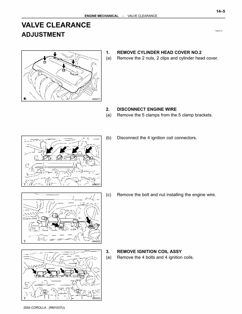
140OE–01
A65077
A64021
A64022
A64023
–ENGINE MECHANICAL VALVE CLEARANCE
14–5
2004 COROLLA (RM1037U)
VALVE CLEARANCE
ADJUSTMENT
1. REMOVE CYLINDER HEAD COVER NO.2
(a) Remove the 2 nuts, 2 clips and cylinder head cover.
2. DISCONNECT ENGINE WIRE
(a) Remove the 5 clamps from the 5 clamp brackets.
(b) Disconnect the 4 ignition coil connectors.
(c) Remove the bolt and nut installing the engine wire.
3. REMOVE IGNITION COIL ASSY
(a) Remove the 4 bolts and 4 ignition coils.

A65078
A64058
A64856
ENGINE MECHANICAL
2004 COROLLA (RM1037U)
4. DISCONNECT VENTILATION HOSE
(a) Disconnect the ventilation hose from the cylinder head
cover.
5. DISCONNECT VENTILATION HOSE NO.2
(a) Disconnect the ventilation hose from the cylinder head
cover.
6. REMOVE CYLINDER HEAD COVER SUB–ASSY
(a) Remove the 9 bolts, 2 seal washers, 2 nuts, 3 clamp
brackets and cylinder head cover.
7. REMOVE ENGINE UNDER COVER RH
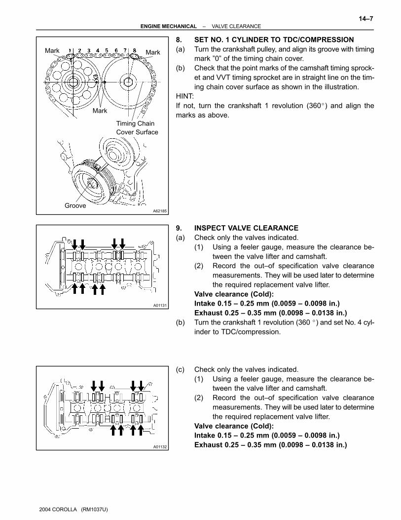
A62185
Mark Mark
Mark
Timing Chain
Cover Surface
Groove
A01131
A01132
–ENGINE MECHANICAL VALVE CLEARANCE
14–7
2004 COROLLA (RM1037U)
8. SET NO. 1 CYLINDER TO TDC/COMPRESSION
(a) Turn the crankshaft pulley, and align its groove with timing
mark ”0” of the timing chain cover.
(b) Check that the point marks of the camshaft timing sprock-
et and VVT timing sprocket are in straight line on the tim-
ing chain cover surface as shown in the illustration.
HINT:
If not, turn the crankshaft 1 revolution (360�) and align the
marks as above.
9. INSPECT VALVE CLEARANCE
(a) Check only the valves indicated.
(1) Using a feeler gauge, measure the clearance be-
tween the valve lifter and camshaft.
(2) Record the out–of specification valve clearance
measurements. They will be used later to determine
the required replacement valve lifter.
Valve clearance (Cold):
Intake 0.15 – 0.25 mm (0.0059 – 0.0098 in.)
Exhaust 0.25 – 0.35 mm (0.0098 – 0.0138 in.)
(b) Turn the crankshaft 1 revolution (360 �) and set No. 4 cyl-
inder to TDC/compression.
(c) Check only the valves indicated.
(1) Using a feeler gauge, measure the clearance be-
tween the valve lifter and camshaft.
(2) Record the out–of specification valve clearance
measurements. They will be used later to determine
the required replacement valve lifter.
Valve clearance (Cold):
Intake 0.15 – 0.25 mm (0.0059 – 0.0098 in.)
Exhaust 0.25 – 0.35 mm (0.0098 – 0.0138 in.)
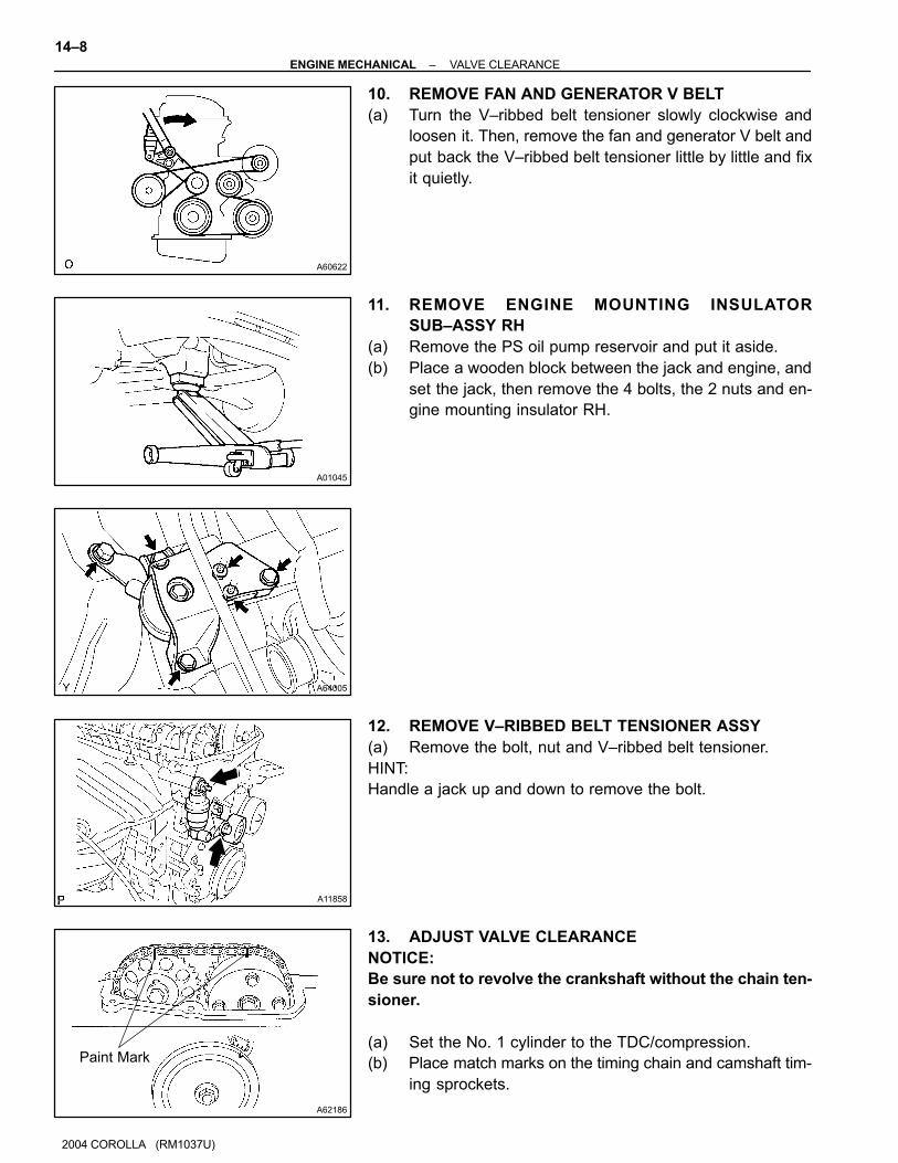
A60622
A01045
A64005
A11858
A62186
Paint Mark
14–8–ENGINE MECHANICAL VALVE CLEARANCE
2004 COROLLA (RM1037U)
10. REMOVE FAN AND GENERATOR V BELT
(a) Turn the V–ribbed belt tensioner slowly clockwise and
loosen it. Then, remove the fan and generator V belt and
put back the V–ribbed belt tensioner little by little and fix
it quietly.
11. REMOVE ENGINE MOUNTING INSULATOR
SUB–ASSY RH
(a) Remove the PS oil pump reservoir and put it aside.
(b) Place a wooden block between the jack and engine, and
set the jack, then remove the 4 bolts, the 2 nuts and en-
gine mounting insulator RH.
12. REMOVE V–RIBBED BELT TENSIONER ASSY
(a) Remove the bolt, nut and V–ribbed belt tensioner.
HINT:
Handle a jack up and down to remove the bolt.
13. ADJUST VALVE CLEARANCE
NOTICE:
Be sure not to revolve the crankshaft without the chain ten-
sioner.
(a) Set the No. 1 cylinder to the TDC/compression.
(b) Place match marks on the timing chain and camshaft tim-
ing sprockets.
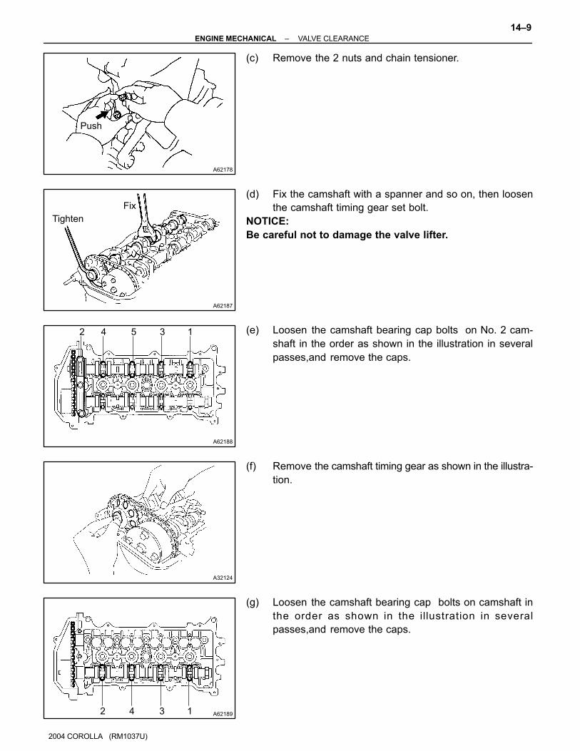
A62178
Push
A62187
Fix
Tighten
A62188
2 4 5 3 1
A32124
A621892 4 3 1
–ENGINE MECHANICAL VALVE CLEARANCE
14–9
2004 COROLLA (RM1037U)
(c) Remove the 2 nuts and chain tensioner.
(d) Fix the camshaft with a spanner and so on, then loosen
the camshaft timing gear set bolt.
NOTICE:
Be careful not to damage the valve lifter.
(e) Loosen the camshaft bearing cap bolts on No. 2 cam-
shaft in the order as shown in the illustration in several
passes,and remove the caps.
(f) Remove the camshaft timing gear as shown in the illustra-
tion.
(g) Loosen the camshaft bearing cap bolts on camshaft in
the order as shown in the illustration in several
passes,and remove the caps.

A32125
A32556
A01082
A62195
Painted Link
Timing Mark
14–10–ENGINE MECHANICAL VALVE CLEARANCE
2004 COROLLA (RM1037U)
(h) Remove the camshaft with holding the timing chain.
(i) Tie the timing chain with a string as shown in the illustra-
tion.
NOTICE:
Be careful not to drop anything inside the timing chain cov-
er.
(j) Remove the valve lifters.
(k) Using a micrometer, measure the thickness of the re-
moved lifter.
(l) Calculate the thickness of a new lifter so that the valve
clearance comes within the specified value.
A Thickness of new lifter
B Thickness of used lifter
C Measured valve clearance
Valve clearance:
Intake A = B + (C – 0.20 mm (0.0079 in.)
Exhaust A = B + (C – 0.30 mm (0.0118 in.)
HINT:
� Select a new lifter with a thickness as close as possible
to the calculated values.
� Lifter are available in 35 sizes in increments of 0.020 mm
(0.0008 in.), from 5.060 mm (0.1992 in.) to 5.740 mm
(0.2260 in.).
(m) As shown in the illustration, install the timing chain on the
camshaft timing gear, with the painted links aligned with
the timing marks on the camshaft timing sprocket.

A62196
4 1 2 3
A62197
Painted Link
Timing Mark
A32124
A621983 1 2 45
6
7
A62187
Fix
Tighten
–ENGINE MECHANICAL VALVE CLEARANCE
14–11
2004 COROLLA (RM1037U)
(n) Examine the front marks and numbers and tighten the
bolts in the order shown in the illustration.
Torque: 13 N⋅m (133 kgf⋅cm, 10 ft⋅lbf)
(o) Put the camshaft No.2 on the cylinder head with the
painted links of the chain aligned with the timing mark on
the camshaft timing sprocket.
(p) Tighten the camshaft timing gear set bolt temporarily.
(q) Examine the front marks and numbers and tighten the
bolts in the order shown in the illustration.
Torque: 13 N⋅m (133 kgf⋅cm, 10 ft⋅lbf)
(r) Install the bearing cap No. 1.
Torque: 23 N⋅m (235 kgf⋅cm, 17 ft⋅lbf)
(s) Fix the camshaft with a spanner and so on, then tighten
the camshaft timing gear set bolt.
Torque: 54 N⋅m (551 kgf⋅cm, 40 ft⋅lbf)
NOTICE:
Be careful not damage the valve lifter.

A62185
Mark Mark
Mark
Timing Chain
Cover Surface
Groove
A62177
Raise
Push
Hook
Pin
A62178
Push
A62180
Disconnect
Hook
Pin Turn
14–12–ENGINE MECHANICAL VALVE CLEARANCE
2004 COROLLA (RM1037U)
(t) Check the match marks on the timing chain and camshaft
timing sprockets, and then the alignment of the pulley
groove with timing mark of the chain cover as shown in the
illustration.
(u) Install chain tensioner.
(1) Check the O–ring is clean, and set the hook as
shown in the illustration.
(2) Apply engine oil to the chain tensioner and install it
with the 2 nuts.
Torque: 9.0 N⋅m (92 kgf⋅cm, 80 in⋅lbf)
NOTICE:
When installing the tensioner, set the hook again if the
hook release the plunger.
(3) Turn the crankshaft counterclockwise, and discon-
nect the plunger knock pin from the hook.
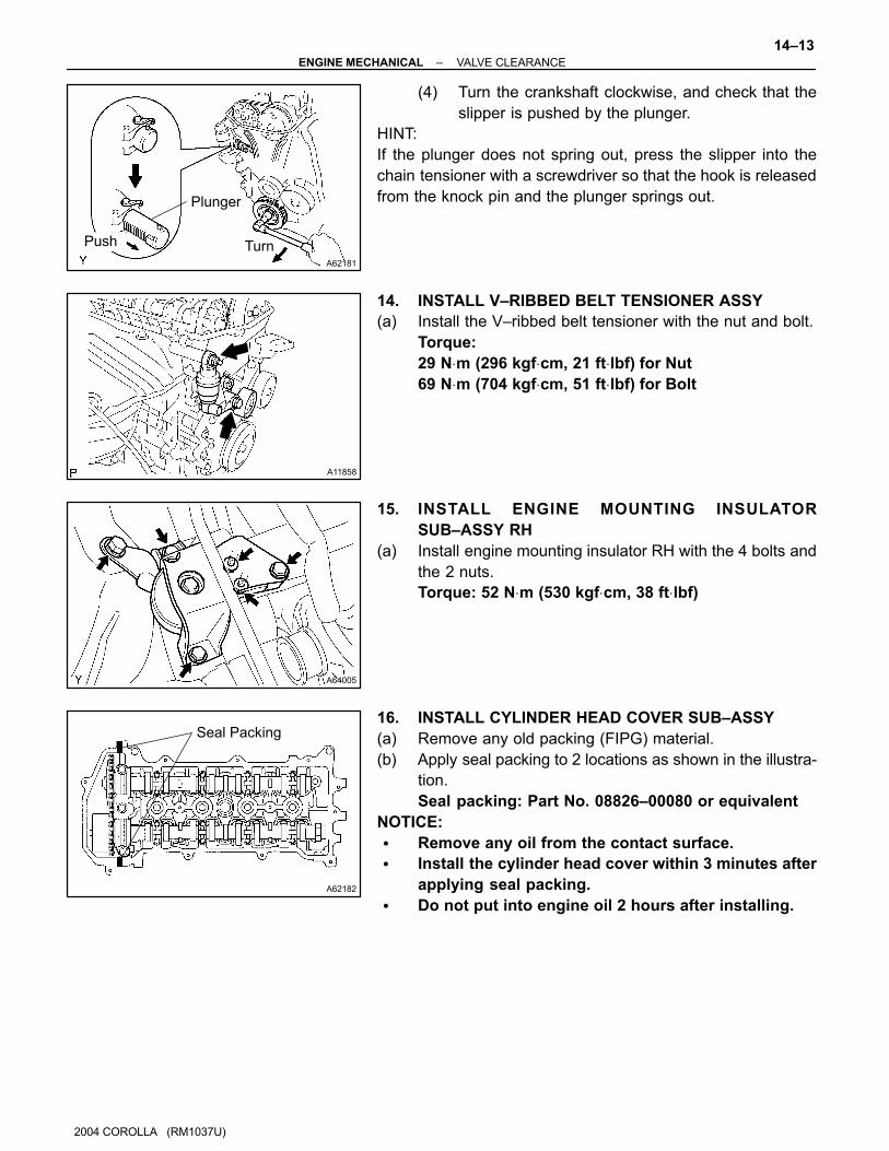
A62181
Plunger
TurnPush
A11858
A64005
A62182
Seal Packing
–ENGINE MECHANICAL VALVE CLEARANCE
14–13
2004 COROLLA (RM1037U)
(4) Turn the crankshaft clockwise, and check that the
slipper is pushed by the plunger.
HINT:
If the plunger does not spring out, press the slipper into the
chain tensioner with a screwdriver so that the hook is released
from the knock pin and the plunger springs out.
14. INSTALL V–RIBBED BELT TENSIONER ASSY
(a) Install the V–ribbed belt tensioner with the nut and bolt.
Torque:
29 N⋅m (296 kgf⋅cm, 21 ft⋅lbf) for Nut
69 N⋅m (704 kgf⋅cm, 51 ft⋅lbf) for Bolt
15. INSTALL ENGINE MOUNTING INSULATOR
SUB–ASSY RH
(a) Install engine mounting insulator RH with the 4 bolts and
the 2 nuts.
Torque: 52 N⋅m (530 kgf⋅cm, 38 ft⋅lbf)
16. INSTALL CYLINDER HEAD COVER SUB–ASSY
(a) Remove any old packing (FIPG) material.
(b) Apply seal packing to 2 locations as shown in the illustra-
tion.
Seal packing: Part No. 08826–00080 or equivalent
NOTICE:
� Remove any oil from the contact surface.
� Install the cylinder head cover within 3 minutes after
applying seal packing.
� Do not put into engine oil 2 hours after installing.

A65687
A
A
A A
A
AAA
A
B B
A64023
A64022
A65077
14–14–ENGINE MECHANICAL VALVE CLEARANCE
2004 COROLLA (RM1037U)
(c) Install the cylinder head cover and cable bracket with the
9 bolts, 2 seal washers and 2 nuts. Uniformly tighten the
bolts and nuts, in the several passes.
Torque:
A 11 N⋅m (112 kgf⋅cm, 8 ft⋅lbf)
B 9.0 N⋅m (92 kgf⋅cm, 80 in⋅lbf)
17. INSTALL IGNITION COIL ASSY
(a) Install the 4 ignition coils with the 4 bolts.
Torque: 9.0 N⋅m (92 kgf⋅cm, 80 in.⋅lbf)
18. INSTALL ENGINE WIRE
(a) Install the engine wire with the bolt and nut.
Torque: 9.0 N⋅m (92 kgf⋅cm, 80 in.⋅lbf)
19. INSTALL CYLINDER HEAD COVER NO.2
(a) Install the cylinder head cover with the 2 nuts and 2 clips.
Torque: 7.0 N⋅m (71 kgf⋅cm, 62 in.⋅lbf)
Related Documents
![STANDOX TOYOTA 2010 [Kompatibilitätsmodus]info.pages.color.tc/Yellowpages/SX/TOYOTA/TOYOTA Colour Info.pdf · TOYOTA MODELS / MODELLE VIN / TYPENSCHILD 01 Corolla Corolla Fielder](https://static.cupdf.com/doc/110x72/5b5543817f8b9a575f8de257/standox-toyota-2010-kompatibilitaetsmodusinfopagescolortcyellowpagessxtoyotatoyota.jpg)