Bedienungsanleitung Infrarot-Temperatursensor Operating instructions Infrared temperature sensor Notice d'utilisation Capteur de température infrarouge TW70xx 7 0 6 2 2 9 / 0 0 0 9 / 2 0 1 2 DE UK FR

Welcome message from author
This document is posted to help you gain knowledge. Please leave a comment to let me know what you think about it! Share it to your friends and learn new things together.
Transcript

8/13/2019 Manual sensor temperatura TW7001.pdf
http://slidepdf.com/reader/full/manual-sensor-temperatura-tw7001pdf 1/80
BedienungsanleitungInfrarot-Temperatursensor
Operating instructionsInfrared temperature sensor
Notice d'utilisation
Capteur de température infrarouge
TW70xx
7 0 6 2 2 9
/ 0 0
0 9
/ 2 0 1 2
DE
UK
FR
8/13/2019 Manual sensor temperatura TW7001.pdf
http://slidepdf.com/reader/full/manual-sensor-temperatura-tw7001pdf 2/80
1
Inhaltsverzeichnis1 Allgemeines .......................................................... 3
1.1 Informationen zur Bedienungsanleitung ......... 3 1.2 Symbolerklärung ............................................ 3 1.3 Haftung und Gewährleistung ......................... 4 1.4 Urheberschutz................................................ 4
2 Sicherheit .............................................................. 4 2.1 Bestimmungsgemäße Verwendung ............... 4 2.2 Verantwortung des Betreibers ........................ 5 2.3 Sicherheitsbestimmungen .............................. 5 2.4 Funkentstörung, EMV Festigkeit ................... 5
3 Bestimmung und Verwendung ........................... 6 4 Funktion ................................................................ 7
4.1 Schaltschwelle ............................................... 7 4.2 Einschaltverzögerung .................................... 8 4.3 Ausschaltverzögerung ................................... 8 4.4 Ausgangssignal .............................................. 8 4.5 Schaltfunktionen ............................................ 9 4.6 Interne Signalverarbeitung ............................. 9
5 Elektrischer Anschluss ..................................... 10 6 Schirmung und Erdung ..................................... 12
6.1 Potentialausgleich ........................................ 12 7 Bedienelemente und Display ............................ 12 8 Menü .................................................................... 14
8.1 Menü Out 1 .................................................. 14 8.2 Menü Out 2 .................................................. 15 8.3 Menü Testfunktion, Werkseinstellungen ...... 16
9 Menü-Erläuterung .............................................. 17 9.1 Einstellebene ............................................... 17 9.2 Parameter Ebene ......................................... 17
10
Parametrieren ..................................................... 18
10.1 Parametriervorgang allgemein ..................... 18 10.2 Testfunktion ................................................. 20

8/13/2019 Manual sensor temperatura TW7001.pdf
http://slidepdf.com/reader/full/manual-sensor-temperatura-tw7001pdf 3/80
2
11 Betrieb ................................................................. 21 11.1 Anzeige der Konfigurationsparameter .......... 21 11.2 Umgebungstemperatur ................................ 21 11.3 Fehleranzeigen ............................................ 21 12 Wartung und Pflege ........................................... 22 12.1 Reinigung der Objektivlinse ......................... 22
13 Transport, Verpackung und Entsorgung ......... 23 13.1 Transport - Inspektion .................................. 23 13.2 Verpackung .................................................. 23
14 Lizenzinformation .............................................. 24 15 Werkseinstellungen ........................................... 25

8/13/2019 Manual sensor temperatura TW7001.pdf
http://slidepdf.com/reader/full/manual-sensor-temperatura-tw7001pdf 4/80
3
1 Allgemeines
1.1 Informationen zur Bedienungsanleitung
Diese Bedienungsanleitung soll den Anwender in dieLage versetzen, den Infrarot-Temperatursensor und daserforderliche Zubehör sachgerecht zu installieren.Vor Beginn der Installationsarbeiten ist die Bedienungs-anleitung, insbesondere das Kapitel Sicherheit, vollstän-dig zu lesen und zu verstehen! Die Bedienungsanleitungmit den Sicherheitshinweisen sowie die für den Einsatz-bereich gültigen UV-Vorschriften sind unbedingt zu be-
achten!
1.2 Symbolerklärung
Wichtige Hinweise in dieser Bedienungsanleitung sinddurch Symbole gekennzeichnet.
ACHTUNG ! Dieses Symbol kennzeichnet Hinweise, deren Nichtbe-achtung Beschädigungen, Fehlfunktionen und/oder einAusfall des Gerätes zur Folge haben kann.
HINWEIS !
Dieses Symbol hebt Tipps und Informationen hervor, diefür eine effiziente und störungsfreie Bedienung des Ge-rätes zu beachten sind.
► HandlungsanweisungDieses Symbol fordert auf eine Aktion auszuführen
Reaktion, ErgebnisDieses Symbol zeigt das Ergebnis der Aktion

8/13/2019 Manual sensor temperatura TW7001.pdf
http://slidepdf.com/reader/full/manual-sensor-temperatura-tw7001pdf 5/80
4
1.3 Haftung und Gewährleistung
Alle Angaben und Hinweise in dieser Bedienungsanlei-tung wurden unter Berücksichtigung der geltenden Vor-
schriften, des aktuellen ingenieurtechnischen Entwick-lungsstandes sowie unserer langjährigen Erkenntnisseund Erfahrungen zusammengestellt.
1.4 Urheberschutz
Die Bedienungsanleitung ist vertraulich zu behandeln.Sie ist ausschließlich für die mit dem Gerät beschäftigtenPersonen bestimmt. Die Überlassung der Bedienungs-anleitung an Dritte ohne schriftliche Zustimmung desHerstellers ist nicht zulässig. Bei Erfordernis wenden Siesich bitte an den Hersteller.
2 Sicherheit
Dieser Abschnitt gibt einen Überblick über alle wichtigenSicherheitsaspekte für einen optimalen Schutz des Per-sonals sowie über den sicheren und störungsfreien Be-trieb des Gerätes.
2.1 Bestimmungsgemäße Verwendung
Der Infrarot-Temperatursensor ist ausschließlich zum
Gebrauch der in dieser Bedienungsanleitung aufgeführ-ten Verwendungsmöglichkeit bestimmt.
Diese Bedienungsanleitung ist vor Beginn allerArbeiten am und mit dem Gerät, insbesondere vorder Inbetriebnahme, sorgfältig durchzulesen! Für
Schäden und Störungen, die sich aus der Nicht- beachtung der Bedienungsanleitung ergeben,übernimmt der Hersteller keine Haftung.

8/13/2019 Manual sensor temperatura TW7001.pdf
http://slidepdf.com/reader/full/manual-sensor-temperatura-tw7001pdf 6/80
5
Die Betriebssicherheit ist nur bei bestimmungsgemäßerVerwendung des Gerätes gewährleistet.
2.2 Verantwortung des Betreibers
Das Gerät darf nur in technisch einwandfreiem und be-
triebssicheren Zustand betrieben werden.
2.3 Sicherheitsbestimmungen
Dieses Gerät wird mit Niederspannung (10 - 34 V DC)versorgt. Die Spannungsversorgung muss den Bestim-mungen der EN50178, SELV, PELV entsprechen.
2.4 Funkentstörung, EMV Festigkeit
Die Geräte entsprechen den Schutzanforderungen derEG-Richtlinie 89/336/EWG geändert durch 91/263/EWG;92/31/EWG; 93/68/EWG über elektromagnetische Ver-träglichkeit (EMV-Gesetz).Europäische Normen: EN 61000 - 6 - 4
EN 61000 - 6 - 2EN 61000 - 4 - 2/-3/-4/-6EN 55011
Jede über die bestimmungsgemäße Verwen-dung hinausgehende und/oder andersartigeVerwendung des Gerätes ist untersagt und giltals nicht bestimmungsgemäß.Ansprüche jeglicher Art gegen den Herstellerund/oder seine Bevollmächtigten wegen Schä-den aus nicht bestimmungsgemäßer Verwen-
dung des Gerätes sind ausgeschlossen.
Für alle Schäden bei nicht bestimmungsgemä-ßer Verwendung haftet allein der Betreiber.

8/13/2019 Manual sensor temperatura TW7001.pdf
http://slidepdf.com/reader/full/manual-sensor-temperatura-tw7001pdf 7/80
6
Bei Anschluss an ein Netzteil muss sichergestellt sein,dass dieses Netzteil ebenfalls diesen Bestimmungen
entspricht.Beim Zusammenschalten mit nicht einwandfrei entstör-ten anderen peripheren Geräten können Funkstörungenentstehen, die dann im einzelnen Fall zusätzliche Funk-entstörmaßnahmen erfordern.
3 Bestimmung und Verwendung
Der Infrarot-Temperatursensor erfasst und überwachtberührungslos Temperaturen bzw. Temperaturbereiche.
Hierbei erfasst der Sensor die abgestrahlte Infrarotstrah-lung von Objekten und setzt diese in ein elektrischesSchaltsignal um.
Der entscheidende Vorteil dieser Sensoren besteht da-rin, dass kein mechanischer Kontakt zwischen Objektund Sensor besteht.
Daraus ergeben sich folgende typische Anwendungen:
• an sich bewegenden oder schwer zugänglichen
Objekten• an spannungsführenden oder oberflächen-behandelten Objekten
• an klebenden Materialien oder aggressiver Medien• Anwendungen, wo kurze Reaktionszeiten ge-
wünscht sind

8/13/2019 Manual sensor temperatura TW7001.pdf
http://slidepdf.com/reader/full/manual-sensor-temperatura-tw7001pdf 8/80
7
Das äußerst robuste Edelstahlgehäuse ermöglicht denEinsatz selbst in rauer Industrieumgebung. Die Gerätesind spritzwassergeschützt nach IP65 (DIN 40050)
Der Infrarot-Temperatursensor verfügt über zwei Schalt-kontakte, die je nach Konfiguration als Öffner oderSchließer verwendet werden können.
4 Funktion
Das Gerät überwacht berührungslos die Temperatur.Der Infrarot-Temperatursensor verfügt über zwei Open
Collector Ausgänge. Die Ausgänge können in Kombina-tion genutzt werden. So können z. B. Temperaturberei-che überwacht werden.
• Das Gerät zeigt im Display den prozentualenMesswert bezogen auf den Temperaturbereich an.
• Es erzeugt 2 Ausgangssignale entsprechend der
Parametrierung
OUT1 Schaltsignal für Temperatur-Schwelle 1OUT2 Schaltsignal für Temperatur-Schwelle 2
4.1 Schaltschwelle
• OUTx ändert seinen Schaltzustand beim Über- oder
Unterschreiten der eingestellten Schaltschwelle (SP, RP).
Zuerst wird der Schaltpunkt [SP] als Prozentwert vomMessbereich und danach der Rückschaltpunkt einge-stellt [RP]. Bei Änderung von [SP] ändert sich auchder [RP], so dass die Differenz gleich bleibt.
Der Parameter [RP] kann maximal auf den Wert von[SP] eingestellt werden. Bei gleichen Werten liegt derRückschaltpunkt ½ Digit unter dem Schaltpunkt.

8/13/2019 Manual sensor temperatura TW7001.pdf
http://slidepdf.com/reader/full/manual-sensor-temperatura-tw7001pdf 9/80
8
4.2 Einschaltverzögerung
Mit dem Überschreiten der Schaltschwelle [SP] startetdie eingestellte Zeit [DS]. Nach Ablauf der Zeit schaltet
der Ausgang OUTx. Dieser Zustand bleibt, bis [RP] un-terschritten wird. Wenn [RP] vor Ablauf der Zeit unter-schritten wird, wird die bereits abgelaufene Zeit gelöscht.Diese Funktion kann z. B. eingesetzt werden, um uner-wünschte Störimpulse am Ausgang zu unterdrücken.
• Einschaltverzögerung: [Ox] -> [DS] = xs
4.3 Ausschaltverzögerung
Zur sicheren Erkennung des Ausgangsimpulses z. B. ineiner nachgeschalteten Steuerung kann der Ausgangs-impuls verlängert werden.
• Ausschaltverzögerung: [Ox] -> [DR] = xs
4.4 Ausgangssignal
Bei den Ausgängen sind folgende Schaltfunktionenwählbar:
• Schließer: [Ox] -> [OU]= NO (normally open)
• Öffner: [Ox] -> [OU]= NC (normally closed)

8/13/2019 Manual sensor temperatura TW7001.pdf
http://slidepdf.com/reader/full/manual-sensor-temperatura-tw7001pdf 10/80
9
4.5 Schaltfunktionen
4.6 Interne Signalverarbeitung
Temperaturverlauf
Schaltsignal no
Schaltsignal noMit Ein- undAusschaltver-zögerung
Schaltsignal nc
Schaltsignal ncMit Ein- undAusschaltver-zögerung
8/13/2019 Manual sensor temperatura TW7001.pdf
http://slidepdf.com/reader/full/manual-sensor-temperatura-tw7001pdf 11/80
10
5 Elektrischer Anschluss
► Anlage spannungsfrei schalten► Gerät wie folgt anschließen
Das Gerät darf nur von einer Elektrofachkraft in-stalliert werden. Der Anschluss des Infrarot-Temperatursensors darf nicht bei eingeschalte-ter Spannungsquelle erfolgen. Befolgen Sie dieinternationalen Vorschriften zur Errichtungelektrischer Anlagen.
Emissionsgrad von Materialien
Der Infrarot-Temperatursensor reagiert auf die
vom Objekt abgestrahlte Wärme- oder Infrarot-strahlung. Diese ist abhängig vom Material undder Oberfläche. Die Fähigkeit der Wärmestrahlungwird durch den Emissionsgrad definiert. BlankeMetalle oder Aluminium besitzen beispielsweiseeinen sehr geringen Emissionsgrad. Die an einemSchwarzen (Idealen) Strahler kalibrierten Schalt-
sensoren erfassen daher an Materialien mit niedri-gem Emissionsgrad eine wesentlich geringereStrahlung. Die Schaltschwelle ist daher auf einekleinere Schalttemperatur einzustellen.

8/13/2019 Manual sensor temperatura TW7001.pdf
http://slidepdf.com/reader/full/manual-sensor-temperatura-tw7001pdf 12/80
11
PIN 1 BN (braun) L+PIN 2 WH (weiß) Open Collector Schaltausgang 2
Imax = 150 mAPIN 5 GY (grau) Test InputPIN 4 BK (schwarz) Open Collector Schaltausgang 1
Imax = 150 mAPIN 3 BU (blau) L-
Um elektrische und/oder magnetische Felder vomInfrarot-Temperatursensor fernzuhalten, ist ein ge-schirmtes Kabel zu verwenden. Der Schirm mussüber das Steckergehäuse mit dem Gehäuse ver-bunden sein.
Beim Schalten von induktiven Lasten ist eineFreilaufdiode zu verwenden.
8/13/2019 Manual sensor temperatura TW7001.pdf
http://slidepdf.com/reader/full/manual-sensor-temperatura-tw7001pdf 13/80
12
6 Schirmung und Erdung
6.1 Potentialausgleich
Das Gehäuse des Infrarot-Temperatursensors ist überden Anschlussstecker des Kabels mit der Abschirmungverbunden!Bei Potentialdifferenzen zwischen den Erdungspunktenkann über den beidseitig angeschlossenen Schirm einAusgleichsstrom fließen.Verlegen Sie in diesem Fall eine zusätzliche Potential-ausgleichsleitung.
Um Ausgleichsströme zu vermeiden, kann der Infrarot-Temperatursensor auch isoliert montiert werden. DerSchirm muss mit der Anlagenerde verbunden werden.
7 Bedienelemente und Display
Am Infrarot-Temperatursensor TW70xx befinden sich ein2-stelliges Display, 3 Taster und 2 LED’s. Das Displayzeigt im Messbetrieb den prozentualen Wert bezogenauf den Temperaturbereich an.
Ohne isolierte Montage und ohne Potentialaus-gleich darf die Störspannung am Infrarot-Tempe-
ratursensor maximal 48 V betragen.
8/13/2019 Manual sensor temperatura TW7001.pdf
http://slidepdf.com/reader/full/manual-sensor-temperatura-tw7001pdf 14/80
13
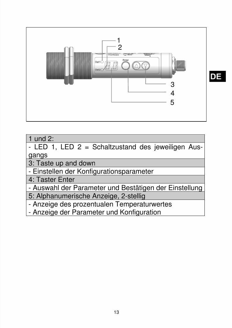
1 und 2:- LED 1, LED 2 = Schaltzustand des jeweiligen Aus-gangs3: Taste up and down
- Einstellen der Konfigurationsparameter4: Taster Enter- Auswahl der Parameter und Bestätigen der Einstellung5: Alphanumerische Anzeige, 2-stellig- Anzeige des prozentualen Temperaturwertes- Anzeige der Parameter und Konfiguration
2
3
4
5

8/13/2019 Manual sensor temperatura TW7001.pdf
http://slidepdf.com/reader/full/manual-sensor-temperatura-tw7001pdf 15/80
14
8 Menü
8.1 Menü Out 1

8/13/2019 Manual sensor temperatura TW7001.pdf
http://slidepdf.com/reader/full/manual-sensor-temperatura-tw7001pdf 16/80
15
8.2 Menü Out 2

8/13/2019 Manual sensor temperatura TW7001.pdf
http://slidepdf.com/reader/full/manual-sensor-temperatura-tw7001pdf 17/80
16
8.3 Menü Testfunktion, Werkseinstellungen

8/13/2019 Manual sensor temperatura TW7001.pdf
http://slidepdf.com/reader/full/manual-sensor-temperatura-tw7001pdf 18/80
17
9 Menü-Erläuterung
9.1 Einstellebene
Parameter Funktion Bemerkungen
O1 Out1 Einstellungen fürOutput 1
O2 Out2Einstellungen fürOutput 2
TF TestfunktionAktivierung der Test-funktion zum Selbst-test
RSRücksetzen aufWerkseinstellungen
Die eingestellten Pa-rameter werden aufdie Werkseinstellun-gen zurückgesetzt
9.2 Parameter Ebene
Parameter Funktion Bemerkungen
SP EinschaltpunktWert in % vomMessbereich
RP Ausschaltpunkt
Wert in % vomMessbereichImmer(≤ Schalt-
punkt)
OU Ausgangsfunktion
NO normallyopenedNC normallyclosed
DS Einschaltverzögerung Wert in „s“ *DR Ausschaltverzögerung Wert in „s“ *
EN End Menü verlassen
* Maximal 9,9 s in 0,1 s Schritten
8/13/2019 Manual sensor temperatura TW7001.pdf
http://slidepdf.com/reader/full/manual-sensor-temperatura-tw7001pdf 19/80
18
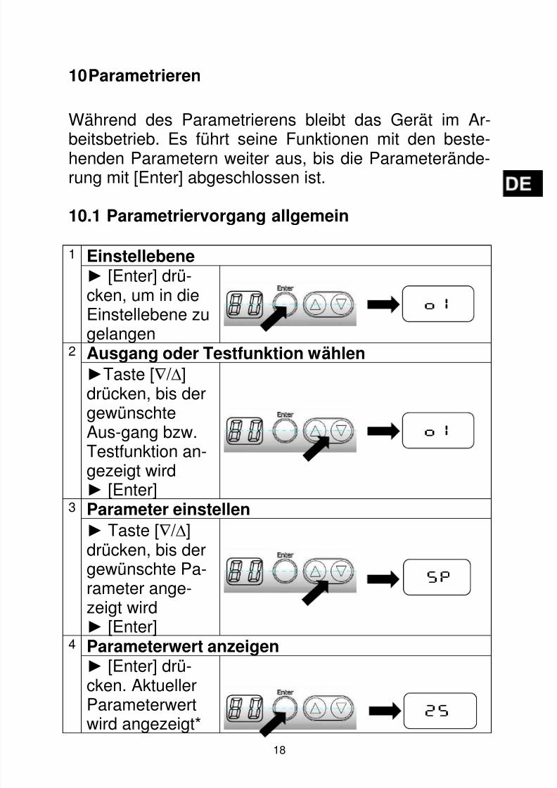
10 Parametrieren
Während des Parametrierens bleibt das Gerät im Ar-
beitsbetrieb. Es führt seine Funktionen mit den beste-henden Parametern weiter aus, bis die Parameterände-rung mit [Enter] abgeschlossen ist.
10.1 Parametriervorgang allgemein
1 Einstellebene
► [Enter] drü-cken, um in dieEinstellebene zugelangen
2 Ausgang oder Testfunktion wählen
►Taste [∇ / ∆]drücken, bis der
gewünschteAus-gang bzw.Testfunktion an-gezeigt wird► [Enter]
3 Parameter einstellen
► Taste [∇ / ∆]
drücken, bis dergewünschte Pa-rameter ange-zeigt wird► [Enter]
4 Parameterwert anzeigen► [Enter] drü-
cken. AktuellerParameterwertwird angezeigt*
O1
O1
SP
25
8/13/2019 Manual sensor temperatura TW7001.pdf
http://slidepdf.com/reader/full/manual-sensor-temperatura-tw7001pdf 20/80
19
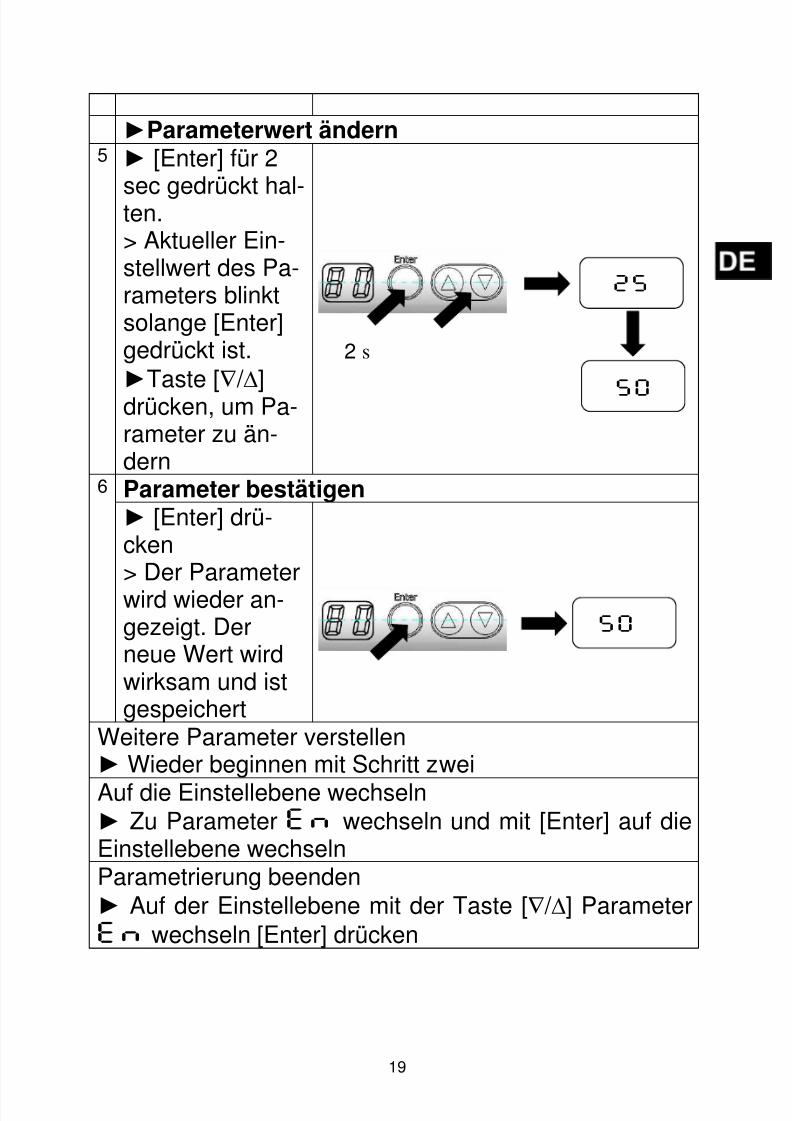
►Parameterwert ändern5 ► [Enter] für 2
sec gedrückt hal-ten.> Aktueller Ein-stellwert des Pa-rameters blinktsolange [Enter]gedrückt ist.►Taste [∇ / ∆]drücken, um Pa-rameter zu än-dern
6 Parameter bestätigen► [Enter] drü-cken> Der Parameterwird wieder an-gezeigt. Derneue Wert wirdwirksam und istgespeichert
Weitere Parameter verstellen► Wieder beginnen mit Schritt zwei
Auf die Einstellebene wechseln► Zu Parameter EN wechseln und mit [Enter] auf dieEinstellebene wechseln
Parametrierung beenden► Auf der Einstellebene mit der Taste [∇ / ∆] ParameterEN wechseln [Enter] drücken
25
50
2 s
50

8/13/2019 Manual sensor temperatura TW7001.pdf
http://slidepdf.com/reader/full/manual-sensor-temperatura-tw7001pdf 21/80
20
* Der Infrarot-Temperatursensor zeigt für 30 s den zuge-hörigen Parameterwert an. Nach 30 s ohne Tastenbe-stätigung erfolgt der Rücksprung auf den Messwert.
Tasten [∇∆] gleichzeitig für 10 s drücken.> Anzeige blinkt 1x.
10.2 Testfunktion
Zur Überprüfung der kompletten Signalverarbeitung so-
wie der Schaltausgänge verfügt der Infrarot-Temperatursensor über eine Interne Testfunktion. DieTestfunktion wird per Tastenkombination oder über einstatisches Signal (10 – 34 V) an PIN 5 ausgelöst. DasSignal am Testeingang muss > 400 ms anliegen. DerTest simuliert ein Strahlungsdetektorsignal. Die Anzeigezeigt „OL“. Zur Deaktivierung der Testfunktion mussdas statische Signal < 6 V für die Dauer von 0,3 s an-stehen. Bei Aktivierung über die Tasten bleibt das Gerätfür 10 s in diesem Modus.
Das Gerät verfügt über eine Tastensperre. Zumaktivieren/deaktivieren der Tastensperre wiefolgt vorgehen:
Durch gleichzeitiges drücken der Tasten [∇∆] kanneine Ebene direkt verlassen werden (ESC Funkti-on).
Wenn die Testfunktion nicht verwendet wird, ist derTesteingang (PIN 5) auf Minus Versorgung zu le-gen. Alternativ kann auch eine 4 polige Kabeldoseverwendet werden, bei der PIN 5 nicht belegt ist.
8/13/2019 Manual sensor temperatura TW7001.pdf
http://slidepdf.com/reader/full/manual-sensor-temperatura-tw7001pdf 22/80
21
11 Betrieb
Nach dem Einschalten der Versorgungsspannung führtder Infrarot-Temperatursensor eine interne Initialisierung
und Selbstdiagnose durch. Nach ca. 0,5 s ist der Infra-rot-Temperatursensor betriebsbereit und startet dieMess- und Auswertfunktion.
11.1 Anzeige der Konfigurationsparameter
[Enter] drücken und den gewünschten Output wählen.[Enter] drücken, um in die Parameterebene zu wech-
seln.[∇ / ∆] Taste drücken, bis der gewünschte Parameter
angezeigt wird.[Enter] drücken
> Das Gerät zeigt für 30 s den zugehörigen Parameter-wert an. Danach geht es in den Run-Modus zurück.
11.2 UmgebungstemperaturDie maximale Umgebungstemperatur für den Infrarot-Temperatursensor beträgt 65 °C. Wird der Infrarot-Temperatursensor bei Temperaturen > 65 °C betrieben,muss der Infrarot-Temperatursensor gekühlt oder z. B.durch ein Abschirmblech gegen die Strahlungswärmegeschützt werden.
11.3 Fehleranzeigen
Überlast Ausgänge Die LED des jeweiligenAusgangs blinkt mit 2 Hz.Die Anzeige zeigt denProzesswert an
Übertemperatur im Gerät Anzeige "OT" und derProzesswert wechseln
8/13/2019 Manual sensor temperatura TW7001.pdf
http://slidepdf.com/reader/full/manual-sensor-temperatura-tw7001pdf 23/80
22
mit 0,5 Hz. Die LED’szeigen den Schaltzustanddes Ausganges an.
Fehlerhafter Anschluss derVersorgungsspannung Beide LED‘s blinken mit 2Hz. Die Anzeige zeigt denProzesswert an.
Versorgungsspannung≤ 7,8 V
Beide LED’s, Anzeigeund Schaltausgänge sinddeaktiviert.(Bei Spannungen ≥ 8 V
schaltet sich das Gerätein. Die Schaltausgängewerden aktiviert)
Messbereichsunterschreitung Die Anzeige zeigt „UL“Messbereichsüberschreitung Die Anzeige zeigt „OL“
12 Wartung und Pflege
12.1 Reinigung der ObjektivlinseEine Verschmutzung der Objektivlinse führt zu einerFehlanzeige des Messwertes. Deshalb ist die Linse re-gelmäßig zu überprüfen und bei Bedarf zu reinigen.Staub ist zunächst durch Freiblasen oder mittels einesweichen Pinsels zu entfernen. Die im Handel für die Lin-senreinigung angebotenen Tücher können verwendet
werden. Geeignet sind auch saubere, weiche und fussel-freie Tücher.
Stärkere Verunreinigungen können mit handelsüblichemGeschirrspülmittel oder Flüssigseife entfernt werden.Anschließend sollte vorsichtig mit klarem Wasser nach-gespült werden. Dabei muss der Infrarot-Temperatur-
sensor mit der Linse nach unten gehalten werden.Beim Reinigen sollte möglichst wenig Druck auf die Lin-se ausgeübt werden, um ein Verkratzen zu vermeiden.

8/13/2019 Manual sensor temperatura TW7001.pdf
http://slidepdf.com/reader/full/manual-sensor-temperatura-tw7001pdf 24/80
23
13 Transport, Verpackung und Entsorgung
13.1 Transport - Inspektion
Die Lieferung ist bei Erhalt unverzüglich auf Vollständig-keit und Transportschäden zu prüfen.Bei äußerlich erkennbarem Transportschaden ist die Lie-ferung nicht oder nur unter Vorbehalt entgegen zu neh-men. Der Schadensumfang ist auf den Transportunter-lagen / Lieferschein des Transporteurs zu vermerken.Eine Reklamation ist einzuleiten.Verdeckte Mängel sind sofort nach Erkennen zu rekla-
mieren, da Schadenersatzansprüche nur innerhalb derReklamationsfristen geltend gemacht werden können.
13.2 Verpackung
Die Verpackungsmaterialien sind nach umweltverträgli-chen und entsorgungstechnischen Gesichtspunktenausgewählt und deshalb recycelbar. Die Verpackung istumweltgerecht zu entsorgen.

8/13/2019 Manual sensor temperatura TW7001.pdf
http://slidepdf.com/reader/full/manual-sensor-temperatura-tw7001pdf 25/80
24
14 Lizenzinformation
Die Gerätesoftware enthält Teile aus der avr-libc Bibliothek.
Portions of avr-libc are Copyright (c) 1999-2007Keith Gudger,Bjoern Haase,Steinar Haugen,Peter Jansen,Reinhard Jessich,Magnus Johansson,Artur Lipowski,Marek Michalkiewicz,Colin O'Flynn,Bob Paddock,Reiner Patommel,Michael Rickman,Theodore A. Roth,Juergen Schilling,Philip Soeberg,
Anatoly Sokolov,Nils Kristian Strom,Michael Stumpf,Stefan Swanepoel,Eric B. Weddington,Joerg Wunsch,Dmitry Xmelkov,The Regents of the University of California.All rights reserved.
Redistribution and use in source and binary forms, with or withoutmodification, are permitted provided that the following conditions are met:
* Redistributions of source code must retain the above copyrightnotice, this list of conditions and the following disclaimer.
* Redistributions in binary form must reproduce the above copyrightnotice, this list of conditions and the following disclaimer inthe documentation and/or other materials provided with thedistribution.
* Neither the name of the copyright holders nor the names ofcontributors may be used to endorse or promote products derivedfrom this software without specific prior written permission.
THIS SOFTWARE IS PROVIDED BY THE COPYRIGHT HOLDERS AND CONTRIBUTORS "AS IS"AND ANY EXPRESS OR IMPLIED WARRANTIES, INCLUDING, BUT NOT LIMITED TO, THEIMPLIED WARRANTIES OF MERCHANTABILITY AND FITNESS FOR A PARTICULAR PURPOSEARE DISCLAIMED. IN NO EVENT SHALL THE COPYRIGHT OWNER OR CONTRIBUTORS BELIABLE FOR ANY DIRECT, INDIRECT, INCIDENTAL, SPECIAL, EXEMPLARY, OR
CONSEQUENTIAL DAMAGES (INCLUDING, BUT NOT LIMITED TO, PROCUREMENT OFSUBSTITUTE GOODS OR SERVICES; LOSS OF USE, DATA, OR PROFITS; OR BUSINESSINTERRUPTION) HOWEVER CAUSED AND ON ANY THEORY OF LIABILITY, WHETHER INCONTRACT, STRICT LIABILITY, OR TORT (INCLUDING NEGLIGENCE OR OTHERWISE)ARISING IN ANY WAY OUT OF THE USE OF THIS SOFTWARE, EVEN IF ADVISED OF THEPOSSIBILITY OF SUCH DAMAGE.

8/13/2019 Manual sensor temperatura TW7001.pdf
http://slidepdf.com/reader/full/manual-sensor-temperatura-tw7001pdf 26/80
25
15 Werkseinstellungen
Parameter Werkseinstellung Benutzer-
Einstellung
Out1
SP 25 %RP 23 %OU NO
DS 0 sDR 0 s
Out2
SP 75 %
RP 73 %OU NO
DS 0 sDR 0 s

8/13/2019 Manual sensor temperatura TW7001.pdf
http://slidepdf.com/reader/full/manual-sensor-temperatura-tw7001pdf 27/80
8/13/2019 Manual sensor temperatura TW7001.pdf
http://slidepdf.com/reader/full/manual-sensor-temperatura-tw7001pdf 28/80
1
Contents
1 Miscellaneous ....................................................... 3 1.1 Information about this manual ........................ 3 1.2 Explanation of symbols .................................. 3 1.3 Liability and Warranty .................................... 4 1.4 Copyright ....................................................... 4
2 Safety .................................................................... 4 2.1 Intended use .................................................. 4 2.2 User’s responsiblity ........................................ 5 2.3 Safety requirements ....................................... 5 2.4 Electromagnetic Compatibility ........................ 5
3 General Description ............................................. 6 4 Function ................................................................ 7
4.1 Switching threshold ........................................ 7 4.2 Upper threshold delay .................................... 7 4.3 Lower threshold delay .................................... 8 4.4 Output signal .................................................. 8 4.5 Switching function .......................................... 9 4.6 Internal signal processing .............................. 9
5 Electrical connection ......................................... 10 6 Shielding and Grounding .................................. 12
6.1 Potential Equalisation .................................. 12 7 Operating controls and display ........................ 12 8 Menu .................................................................... 14
8.1 Menu Out1 ................................................... 14 8.2 Menu Out 2 .................................................. 15 8.3 Menu test function, factory reset .................. 16
9 Menu Explanation .............................................. 17 9.1
Configuration layer ....................................... 17
9.2 Parameter Layer .......................................... 17
10 Operating parameters ........................................ 18

8/13/2019 Manual sensor temperatura TW7001.pdf
http://slidepdf.com/reader/full/manual-sensor-temperatura-tw7001pdf 29/80
2
10.1 Setting parameters ....................................... 18 10.2 Diagnostics feature ...................................... 20
11 Operation Mode .................................................. 21 11.1 View operating parameters .......................... 21 11.2 Ambient temperature ................................... 21 11.3 Error indications ........................................... 21
12 Maintenance ....................................................... 22 12.1 Cleaning the lens ......................................... 22
13 Shipping, Packaging and Disposal ................... 23 13.1 Inspecting your shipment ............................. 23 13.2 Packaging .................................................... 23
14 Copyright ............................................................ 24 15 Default settings .................................................. 25

8/13/2019 Manual sensor temperatura TW7001.pdf
http://slidepdf.com/reader/full/manual-sensor-temperatura-tw7001pdf 30/80
3
1 Miscellaneous
1.1 Information about this manual
The Operating Manual shall enable the user to properlyinstall the infrared temperature sensor and the requiredaccessories.
Before starting installation, be sure to read and under-stand this entire manual, in particular the chapter onsafety! The instructions contained in this manual, espe-cially those concerning safety, as well as site-specific
regulations governing accident prevention regulationsmust be complied with at all times!
1.2 Explanation of symbols
Important safety-related references in this manual aremarked with a symbol.
CAUTION !
This symbol indicates important information which, if ne-glected, might result in damage to the instrument or mal-function or breakdown.
PLEASE NOTE !
This symbol points out guidelines which should beheeded for efficient and trouble-free operation.
► ActionThis symbol instructs the operator to take action.
Reaction, ResultThis symbol indicates the result of the action taken.

8/13/2019 Manual sensor temperatura TW7001.pdf
http://slidepdf.com/reader/full/manual-sensor-temperatura-tw7001pdf 31/80
4
1.3 Liability and Warranty
All information compiled in this manual is in accordancewith applicable regulations. The statements made are
based on state-of-the-art technology and reflect our ex-tensive knowledge and many years of experience.
1.4 Copyright
This Operating Manual should be treated as confidential.It is solely intended for use by persons involved with theinstrument. This manual may not be made available to athird party without prior Manufacturer’s consent. Pleasecontact the Manufacturer if the need should arise.
2 Safety
This chapter outlines all important safety aspects to beconsidered for optimum employee protection and to en-sure safe and reliable operations.
2.1 Intended use
The infrared temperature sensor is solely intended foruse as described in this manual. Operational safety canonly be ensured when the instrument is used for its in-
tended purpose.
Always carefully read this Operating Manualbefore beginning any work on or with the in- strument, especially prior to installation andinitial setup! The Manufacturer shall not be
held liable for any damages or malfunctionsarising from a disregard of the warnings andinstructions contained herein.

8/13/2019 Manual sensor temperatura TW7001.pdf
http://slidepdf.com/reader/full/manual-sensor-temperatura-tw7001pdf 32/80
5
2.2 User’s responsiblity
The infrared temperature sensor may only be used whenit is in perfect working condition.
2.3 Safety requirements
The instrument operates at low voltage (10 – 34 V DC).The power supply unit must conform to directiveEN50178, SELV, PELV.
2.4 Electromagnetic Compatibility
The instrument complies with the requirements of EC
Directive 89/336/EEC changed by 91/263/EEC;92/31/EEC; 93/68/EEC relating to radio interferencesuppression and electromagnetic compatibility.
European certification: EN 61000 - 6 - 4EN 61000 - 6 - 2EN 61000 - 4 -2/-3/-4/-6
EN 55011
The use of the infrared temperature sensor forany other purpose beyond what is specified inthis manual is prohibited. Using the instrument in
any other manner will be considered as improp-er.
The Manufacturer/Authorised Agent shall not beheld liable for any damages or loss resultingfrom such unintended or improper use; in thiscase the risk is solely borne by the user.
8/13/2019 Manual sensor temperatura TW7001.pdf
http://slidepdf.com/reader/full/manual-sensor-temperatura-tw7001pdf 33/80
6
When connecting a power supply unit, make sure that isalso conforms to these standards. Radio interferencemay arise if the infrared temperature sensor is intercon-
nected with such peripheral devices which have notbeen properly interference-suppressed. This may ne-cessitate additional interference suppression measures.
3 General Description
The infrared temperature sensor detects temperaturesand monitors temperature ranges without contact.
The sensor detects the infrared energy radiated by a hotobject and converts this to an electric switch signal.
The advantage of this technique is that there is no me-chanical contact between the sensor and the hot object.
The instrument is suitable for the following applications:
• Moving or hard-to-reach objects
• Surface-treated or voltage-carrying objects
• Sticky materials such as dough or aggressivechemicals
• Applications requiring fast response times
The rugged stainless steel housing enables the instru-ment to be used in harsh industrial environments. Theinstruments are splash-proof according to IP65 (DIN40050).
The infrared temperature sensor features two switching
relays which can be custom configured as NC or NOcontacts.

8/13/2019 Manual sensor temperatura TW7001.pdf
http://slidepdf.com/reader/full/manual-sensor-temperatura-tw7001pdf 34/80
7
4 Function
The infrared temperature sensor is equipped with twoopen collector outputs which can be used concurrently.
• The instrument’s display panel shows a value whichis a percentage relating to the temperature range.
• It generates 2 output signals according to the con-figured function
OUT1 Switch signal for temperature threshold 1
OUT2 Switch signal for temperature threshold 2
4.1 Switching threshold
• OUTx changes switching status when the configuredupper and lower thresholds (SP, RP) are exceed-ed.
First set the upper threshold [SP] as a percentaged val-ue based on the temperature span. Then set the lowerthreshold [RP]. When you adjust the upper threshold[SP] the lower threshold [RP] will change accordingly.The span remains the same. The lower threshold [RP]cannot be configured higher than the value of the upperthreshold [SP]. When these parameter values are set to
be equivalent, the lower threshold will be a ½ digit lowerthan the upper threshold.
4.2 Upper threshold delay
Once the sensor has detected a temperature which ex-ceeds the switching threshold [SP] the time delay [DS]starts running. When this delay period has elapsed, the
output OUTx activates switching. This status is sus-tained until the lower threshold [RP] is violated. If thisoccurs before the time delay has elapsed, the delay will

8/13/2019 Manual sensor temperatura TW7001.pdf
http://slidepdf.com/reader/full/manual-sensor-temperatura-tw7001pdf 35/80
8
reset. This function can be used, for example, to sup-press spurious impulse signals at the output.
• Delay: [Ox] -> [DS] = xs
4.3 Lower threshold delay
To make sure the output impulse is correctly identified,e.g. by a downstream control system, the output impulsecan be lengthened.
• Delay: [Ox] -> [DR] = xs
4.4 Output signal
The following switching functions can be selected:
• Normally open contact: [Ox] -> [OU] = NO
• Normally closed contact: [Ox] -> [OU] = NC

8/13/2019 Manual sensor temperatura TW7001.pdf
http://slidepdf.com/reader/full/manual-sensor-temperatura-tw7001pdf 36/80
9
4.5 Switching function
4.6 Internal signal processing
Temperatur profile
Switch signal no
Switch signal noWith upper- andlower thresholddela
Switch signal ncWith upper- andlower thresholddela
Switch signal nc

8/13/2019 Manual sensor temperatura TW7001.pdf
http://slidepdf.com/reader/full/manual-sensor-temperatura-tw7001pdf 37/80
10
5 Electrical connection
► Switch to neutral and verify absence of voltage.► Connect instrument according to the following
schematic:
The infrared temperature sensor may only beinstalled by a skilled, qualified electrician. Do notconnect the instrument while the voltage supplysource is turned on. Please observe internation-al safety regulations at all times.
Emissivity of Materials
The infrared temperature sensor reacts to the
thermal energy (infrared radiation) emitted by anobject. The ability to radiate heat depends on thetype of material and its surface properties. Shinymetals or aluminium, for example, have a very lowemissivity coefficient. An infrared temperaturesensor which has been calibrated by a black bodywill detect less infrared radiation when measuring
a material with low emissivity. In such cases, youshould select a lower switching temperature.

8/13/2019 Manual sensor temperatura TW7001.pdf
http://slidepdf.com/reader/full/manual-sensor-temperatura-tw7001pdf 38/80
11
PIN 1 BN (brown) L+PIN 2 WH (white) Open Collector switching output
2 Imax = 150 mA
PIN 5 GY (grey) Test InputPIN 4 BK (black) Open Collector switching output
1 Imax = 150 mAPIN 3 BU (blue) L-
The infrared temperature sensor must be protectedagainst high voltage and strong electromagneticfields. Use a shielded cable, connecting it via con-nector casing to the device housing.
Use a flyback diode when switching inductiveloads.

8/13/2019 Manual sensor temperatura TW7001.pdf
http://slidepdf.com/reader/full/manual-sensor-temperatura-tw7001pdf 39/80
12
6 Shielding and Grounding
6.1 Potential Equalisation
The infrared temperature sensor housing is connected tothe shielding via the cable connector!
Differences in ground potentials might cause an equalis-ing current to flow between devices through a cableshielded at both ends. In this case, be sure to install anadditional potential equalisation line.
To avoid an equalising current, the infrared temperaturesensor can be mounted electrically insulated. The shield-ing must be connected to the plant’s grounding.
7 Operating controls and display
The IR temperature sensor TW70xx features a 2-digitdisplay, 3 control keys and 2 LEDs. During Run Mode,the display indicates the measurement value as a per-centage relating to the temperature span.
If the infrared temperature sensor is installedwithout an insulator and without potential equali-sation, the interference voltage may not exceed
48V.
2
3
45

8/13/2019 Manual sensor temperatura TW7001.pdf
http://slidepdf.com/reader/full/manual-sensor-temperatura-tw7001pdf 40/80
13
1 and 2:- LED 1. LED 2 = indicates switching status of respec-tive output3: Control key up and down- Adjust configuration parameters4: Control key enter- select parameter and confirm setting5: Alphanumeric display, 2-digit- indicates percentage of temperature value- indicates parameters and configuration

8/13/2019 Manual sensor temperatura TW7001.pdf
http://slidepdf.com/reader/full/manual-sensor-temperatura-tw7001pdf 41/80
14
8 Menu
8.1 Menu Out1

8/13/2019 Manual sensor temperatura TW7001.pdf
http://slidepdf.com/reader/full/manual-sensor-temperatura-tw7001pdf 42/80

8/13/2019 Manual sensor temperatura TW7001.pdf
http://slidepdf.com/reader/full/manual-sensor-temperatura-tw7001pdf 43/80

8/13/2019 Manual sensor temperatura TW7001.pdf
http://slidepdf.com/reader/full/manual-sensor-temperatura-tw7001pdf 44/80
17
9 Menu Explanation
9.1 Configuration layer
Parameter Function Comments
O1 Out1 Settings for Output 1
O2 Out2 Settings for Output 2
TFdiagnostics(test) feature
Activates diagnostics fea-ture for self-test
RS
Resetting tofactory set-tings
The adjusted parameterare reset to factory set-tings
9.2 Parameter Layer
Parameter Function Comments
SPUpperthreshold
Value is % of definedtemperature span
RPLowerthreshold
Value is % of definedtemperature spanAlways (≤ switching point)
OUOutput func-tion
NO normally open
NC normally closed
DS
Upperthreshold
delay
Value in „s“ *
DR
Lowerthresholddelay
Value in „s“ *
EN End Exit menu
* Maximum 9.9 s in 0.1 s increments

8/13/2019 Manual sensor temperatura TW7001.pdf
http://slidepdf.com/reader/full/manual-sensor-temperatura-tw7001pdf 45/80
18
10 Operating parameters
When you reset/adjust the operating parameters the in-
strument remains in run mode. It continues to operate,using the current parameter settings, until you have fin-ished configuring by pressing [Enter].
10.1 Setting parameters
1 Configuration layer
► Press [Enter]to access theconfigurationlayer
2 Select output or diagnostics feature►Press control
key[∇
/ ∆
] until thedisplay showsthe desired out-put or diagnos-tics feature► [Enter]
3 Adjust parameters► Press control
key[∇ / ∆] until thedisplay showsthe desired pa-rameter► [Enter]
4 Show parameter value► Press [Enter]to view currentparameter value*
O1
O1
SP
25
8/13/2019 Manual sensor temperatura TW7001.pdf
http://slidepdf.com/reader/full/manual-sensor-temperatura-tw7001pdf 46/80
19
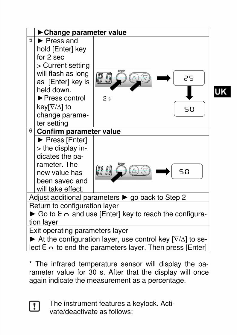
►Change parameter value5 ► Press and
hold [Enter] key
for 2 sec> Current settingwill flash as longas [Enter] key isheld down.►Press control
key[∇ / ∆] to
change parame-ter setting6 Confirm parameter value► Press [Enter]> the display in-dicates the pa-rameter. The
new value hasbeen saved andwill take effect.
Adjust additional parameters► go back to Step 2Return to configuration layer► Go to EN and use [Enter] key to reach the configura-tion layer Exit operating parameters layer
► At the configuration layer, use control key [∇ / ∆] to se-lect EN to end the parameters layer. Then press [Enter]
* The infrared temperature sensor will display the pa-rameter value for 30 s. After that the display will onceagain indicate the measurement as a percentage.
25
50
2 s
The instrument features a keylock. Acti-vate/deactivate as follows:
50

8/13/2019 Manual sensor temperatura TW7001.pdf
http://slidepdf.com/reader/full/manual-sensor-temperatura-tw7001pdf 47/80
20
Press [∇∆] keys simultaneously and hold them downfor 10 sec. > The display will flash once.
10.2 Diagnostics feature
The infrared temperature sensor features an integrateddiagnostics function which can be activated either usingthe control keys or by a static signal (10 – 34 V)on PIN 5.
Voltage must be applied for at least t > 400 ms. The di-agnostics function simulates the detection of infrared ra-diation. The display shows „OL”. To deactivate the di-agnostics function, the static signal must be < 6 V for a
period longer than 0.3 s. If the diagnostics function is ac-tivated using the control keys on the instrument, it willremain in this mode for 10 s. The diagnostics functionchecks the instrument’s signal processing and tests theswitching outputs.
If you press both [∇∆] keys only briefly, you willexit the layer (ESC function).
When the test function is not being used, connect
the test input (PIN 5) to the negative pole of thesupply voltage. Alternatively, use a 4-pin cablesocket (PIN 5 not assigned).

8/13/2019 Manual sensor temperatura TW7001.pdf
http://slidepdf.com/reader/full/manual-sensor-temperatura-tw7001pdf 48/80
21
11 Operation Mode
After connecting the supply voltage the infrared tempera-ture sensor will be automatically initialized and will per-
form a self-diagnosis. After approx. 0.5 s the sensor isready to operate and the instrument runs the signal pro-cessing.
11.1 View operating parameters
Press [Enter] and select the desired output.Press [Enter] to go to the parameters layer.
Press [▼ / ▲] until the display shows the desired pa-rameter.
Press [Enter].> The display will indicate the parameter value for 30 s.After that it returns to Run Mode.
11.2 Ambient temperature
The maximum permissible ambient operating tempera-ture for the infrared temperature sensor is 65 °C. If theinstrument is used in ambient temperatures above 65°C, it must be either cooled or shielded from excess ra-diant heat by means of a deflector plate.
11.3 Error indications
Overload of output Corresponding LED willflash at f = 2.0 Hz
Excess temperature insidedevice
Display alternately shows"OT" and measurementreading at f =0.5 Hz. TheLEDs indicate the output
switching status.Faulty connection of supply Both LEDs flash at f = 2.0

8/13/2019 Manual sensor temperatura TW7001.pdf
http://slidepdf.com/reader/full/manual-sensor-temperatura-tw7001pdf 49/80
22
voltage Hz. Display shows meas-urement reading.
Supply voltage
≤ 7.8 V
Both LEDs, display and
switching outputs are de-activated.(When voltage ≥ 8 V thedevice switches on andthe switching outputs areactivated)
Temp. below lower threshold Display shows „UL“
Temp.above upper threshold Display shows „OL
“
12 Maintenance
12.1 Cleaning the lens
A false reading will be given when the lens is dirty.
Therefore check the lens periodically and clean it, if nec-essary.
Dust can be removed by simply blowing it away or by us-ing a soft brush. A special lens cleaning cloth is ideal,but any soft, clean, lint-free cloth will be suitable.
If the lens is quite dirty, use a very mild liquid detergentand rinse carefully with clear water while holding the de-vice pointed down. Apply as little pressure as possible toavoid scratching the lens.

8/13/2019 Manual sensor temperatura TW7001.pdf
http://slidepdf.com/reader/full/manual-sensor-temperatura-tw7001pdf 50/80
23
13 Shipping, Packaging and Disposal
13.1 Inspecting your shipment
Unpack and inspect the entire shipment immediately up-on receipt to make sure it is complete and undamaged.
If the container/package shows visible signs of damage,please refuse the shipment. If this is not possible, acceptthe shipment on the condition that the freight carrier’sdelivery record is noted with the extent of the damage inorder to file a claim.
Should you discover a concealed loss or damage, reportit to the shipper or freight carrier immediately. If the peri-od for filing claims has expired, you will no longer beable to make any claims for compensation of damage orloss.
13.2 PackagingThe packages used are made of carefully selected, envi-ronmentally compatible materials and are thus recycla-ble. We suggest you retain the packaging for possible fu-ture use; otherwise please ensure that they are disposedof in an ecologically sound manner.

8/13/2019 Manual sensor temperatura TW7001.pdf
http://slidepdf.com/reader/full/manual-sensor-temperatura-tw7001pdf 51/80
24
14 Copyright
The device software contains portions of the avr-libclibrary.
Portions of avr-libc are Copyright (c) 1999-2007Keith Gudger,Bjoern Haase,Steinar Haugen,Peter Yes nsen,Reinhard Jessich,Magnus Johansson,Artur Lipowski,Marek Michalkiewicz,Colin O'Flynn,Bob Paddock,Reiner Patommel,Michael Rickman,Theodore A. Roth,
Juergen Schilling,Philip Soeberg,Anatoly Sokolov,Nils Kristian Strom,Michael Stumpf,Stefan Swanepoel,Eric B. Weddington,Joerg Wunsch,Dmitry Xmelkov,The Regents of the University of California.All rights reserved.
Redistribution and use in source and binary forms, with or withoutmodification, are permitted provided that the following conditions are met:
* Redistributions of source code must retain the above copyrightnotice, this list of conditions and the following disclaimer.
* Redistributions in binary form must reproduce the above copyrightnotice, this list of conditions and the following disclaimer inthe documentation and/or other materials provided with thedistribution.
* Neither the name of the copyright holders nor the names ofcontributors may be used to endorse or promote products derivedfrom this software without specific prior written permission.
THIS SOFTWARE IS PROVIDED BY THE COPYRIGHT HOLDERS AND CONTRIBUTORS "AS IS"AND ANY EXPRESS OR IMPLIED WARRANTIES, INCLUDING, BUT NOT LIMITED TO, THEIMPLIED WARRANTIES OF MERCHANTABILITY AND FITNESS FOR A PARTICULAR PURPOSE
ARE DISCLAIMED. IN NO EVENT SHALL THE COPYRIGHT OWNER OR CONTRIBUTORS BELIABLE FOR ANY DIRECT, INDIRECT, INCIDENTAL, SPECIAL, EXEMPLARY, ORCONSEQUENTIAL DAMAGES (INCLUDING, BUT NOT LIMITED TO, PROCUREMENT OFSUBSTITUTE GOODS OR SERVICES; LOSS OF USE, DATA, OR PROFITS; OR BUSINESSINTERRUPTION) HOWEVER CAUSED AND ON ANY THEORY OF LIABILITY, WHETHER INCONTRACT, STRICT LIABILITY, OR TORT (INCLUDING NEGLIGENCE OR OTHERWISE)ARISING IN ANY WAY OUT OF THE USE OF THIS SOFTWARE, EVEN IF ADVISED OF THEPOSSIBILITY OF SUCH DAMAGE.

8/13/2019 Manual sensor temperatura TW7001.pdf
http://slidepdf.com/reader/full/manual-sensor-temperatura-tw7001pdf 52/80
25
15 Default settings
Parameter Factory
defaultsetting
Customized
configuration
Out1
SP 25 %
RP 23 %
OU NO
DS 0 s
DR 0 s
Out2
SP 75 %RP 73 %
OU NO
DS 0 s
DR 0 s

8/13/2019 Manual sensor temperatura TW7001.pdf
http://slidepdf.com/reader/full/manual-sensor-temperatura-tw7001pdf 53/80
26

8/13/2019 Manual sensor temperatura TW7001.pdf
http://slidepdf.com/reader/full/manual-sensor-temperatura-tw7001pdf 54/80
1
Table des matières
1 Divers .................................................................... 3 1.1 A propos du manuel ....................................... 3 1.2 Explication des symboles ............................... 3 1.3 Validité et garantie ......................................... 4 1.4 Droit de propriété industrielle ......................... 4
2 Consignes de sécurité ......................................... 4 2.1 Utilisation normale ......................................... 5 2.2 Responsabilité de l’utilisateur......................... 5 2.3 Alimentation électrique ................................... 5 2.4 Compatibilité électromagnétique CEM ........... 6
3 Description générale ............................................ 6 4 Fonction ................................................................ 7
4.1 Seuil de commutation .................................... 7 4.2 Tempo du seuil haut [SP] ............................... 8 4.3 Tempo seuil bas ............................................. 8 4.4 Signal de sortie .............................................. 8 4.5 Fonction de communication ........................... 9 4.6 Traitement interne du signal........................... 9
5 Connexion électrique ......................................... 10 6 Blindage et mise à la Terre ................................ 12
6.1 Equipotentiel ................................................ 12 7 Contrôles et afficheur ........................................ 12 8 Menu .................................................................... 14
8.1 Menu sortie Out1 ......................................... 14 8.2 Menu Sortie Out2 ......................................... 15 8.3 Menu des fonctions de tests et de reset usine . 16
9 Description des menus ...................................... 17 9.1
Configuration ................................................ 17
9.2 Sous-menu................................................... 17
10 Opération ............................................................ 18

8/13/2019 Manual sensor temperatura TW7001.pdf
http://slidepdf.com/reader/full/manual-sensor-temperatura-tw7001pdf 55/80
2
10.1 Paramétrage ................................................ 18 10.2 Eléments de diagnostics .............................. 20
11 Fonctionnement ................................................. 21 11.1 Paramètres de fonctionnement .................... 21 11.2 Température ambiante ................................. 21 11.3 Messages d’erreurs ..................................... 21
12 Maintenance ....................................................... 22 12.1 Nettoyage de la lentille ................................. 22
13 Emballage, transport et mise à disposition ..... 22 13.1 Inspection du colis ....................................... 22 13.2 Emballage .................................................... 23 13.3 Droit à la propriété ....................................... 24
14 Paramètres par défaut ....................................... 25

8/13/2019 Manual sensor temperatura TW7001.pdf
http://slidepdf.com/reader/full/manual-sensor-temperatura-tw7001pdf 56/80
3
1 Divers
1.1 A propos du manuel
Le Manuel d’Utilisation a pour objet de guider l’utilisateurlors de l’installation et pour le bon usage du détecteur in-frarouge et de ses accessoires si nécessaire.
Avant d’installer le détecteur infrarouge, veuillez lireavec attention ce manuel et en particulier les consignesde sécurité. Ces consignes ainsi que les régulations etrègles spécifiques du site doivent être respectées en
permanence.
1.2 Explication des symboles
Les références aux consignes de sécurité sont symboli-sées par ce dessin. Le non respect de ces règles peutentrainer des accidents et dommages physiques et ma-
tériels.
ATTENTION !
Ce symbole indique des remarques à suivre pour éviterdes dommages ou des troubles de fonctionnement.
REMARQUE !
Ce symbole indique des remarques à suivre pour uneutilisation optimale et sans perturbation.
► ActionInvite l’utilisateur à faire cette action.
Réaction, résultatRésultat de l’action prise.

8/13/2019 Manual sensor temperatura TW7001.pdf
http://slidepdf.com/reader/full/manual-sensor-temperatura-tw7001pdf 57/80
4
1.3 Validité et garantie
Toutes les informations contenues dans ce manuel sonten adéquation avec les règles et lois actuelles lors de la
rédaction. Les consignes et conseils sont également lefruit de plusieurs années d’expertise dans le domaine dela mesure de température sans contact.
Veuillez à toujours lire ce manuel avent tout nou- velle utilisation et en particulier lors de l’installation
du détecteur infrarouge ! Le constructeur ne pour- rait en aucun cas être tenu responsable d’aucundommage ou mauvaise utilisation en cas du nonrespect des consignes et mises en garde conte- nues dans ce manuel
Veuillez faire en sorte que ce manuel soit accessible à
toute personne qui souhaite intervenir sur cet instru-ment.
1.4 Droit de propriété industrielle
Ce manuel est confidentiel. Il est réservé aux seulespersonnes intervenant sur l’instrument. Le manuel ne
peut être présenté à une tierce partie sans l’accord écritpréalable du constructeur.
2 Consignes de sécurité
Ce chapitre met en lumière les consignes de sécuritépour une utilisation sans danger du détecteur infrarouge.
8/13/2019 Manual sensor temperatura TW7001.pdf
http://slidepdf.com/reader/full/manual-sensor-temperatura-tw7001pdf 58/80
5
2.1 Utilisation normale
Le détecteur infrarouge est destiné à la mesure de tem-
pérature sans contacts définie dans ce manuel. Lesconsignes de sécurité ne sont valides que pour une utili-sation normale.
2.2 Responsabilité de l’utilisateur
Le détecteur infrarouge ne doit être utilisé que dans unparfait état de fonctionnement et en tenant en compte detoutes les règles de sécurité.
2.3 Alimentation électrique
Cet équipement doit être raccordé à une alimentationdistincte en (10 – 34 V DC) répondant aux normesEN50178, SELV, PELV.
Toute autre utilisation que celles définies dansce manuel est considérée non conforme.
Le détecteur infrarouge ne peut être utilisé quepour les applications définies dans ce manuel.Toute autre utilisation est proscrite et le Cons-tructeur ou Agent Autorisé décline toutes res-ponsabilités pour les dommages qui en résulte-raient. L’utilisateur assume seul le ris ue.
8/13/2019 Manual sensor temperatura TW7001.pdf
http://slidepdf.com/reader/full/manual-sensor-temperatura-tw7001pdf 59/80
6
2.4 Compatibilité électromagnétique CEM
Ces instruments répondent aux directives EC
Directive 89/336/EEC et aux avenants 91/263/E,EC92/31/EEC; 93/68/EEC relatifs à la compatibilité élec-tromagnétique (CEM).
Normes européennes : EN 61000 - 6 - 4EN 61000 - 6 - 2
EN 61000 - 4 -2/-3/-4/-6EN 55011
Lors du branchement de l’alimentation, assurez-vous durespect des normes CEM en cours. Des interférencesradio peuvent se produire en cas de branchement du py-romètre à d’autres composants ne respectant les
normes CEM.
3 Description générale
Un détecteur infrarouge mesure l’énergie radiative émisepar un objet, la convertie en température qui déclencheun seuil de commutation.L’avantage de ce détecteur est de pouvoir détecteur la
présence d’objet chaud sans contact. Il n’y a pas depièce mécanique et pas d’usure résultante.
Cet instrument est particulièrement dédié aux applica-tions suivantes:
• Objets en mouvement ou difficile d’accès
• Surface traitée ou électriquement chargée• Environnement corrosif ou agressif
• Applications nécessitant une réponse instantanée

8/13/2019 Manual sensor temperatura TW7001.pdf
http://slidepdf.com/reader/full/manual-sensor-temperatura-tw7001pdf 60/80
7
Le corps en acier inox permet d’employer le détecteurdans un environnement sévère. Il est water-resistant IP65 (DIN 40050).
L’instrument commande deux seuils réglables de com-mutation ouvert/fermé. Le relais peut être ouvert ouferme en cas de dépassement du seuil.
4 Fonction
Le détecteur infrarouge dispose de 2 contacts paramé-
trables et indépendants.
• L’afficheur local fait apparaître le pourcentage de lapleine échelle de mesure.
• Il génère 2 signaux indépendants
OUT1 Commutation pour seuil 1
OUT2 Commutation pour seuil 2
4.1 Seuil de commutation
• OUTx change le statut de commutation lorsque leseuil haut [SP] ou le seuil bas [RP] est dépassé.
Tout d’abord définissez le seuil haut [SP] en pourcen-
tage de la plage de mesure puis le seuil bas [RP].Lorsque vous changez le seuil haut [SP], le seuil bas[RP] est également modifié. La plage de mesure resteinchangée.Bien évidement [RP] ne peut pas être supérieur à [SP].Si [RP] = [SP] alors le seuil bas sera 0.5% en dessous.

8/13/2019 Manual sensor temperatura TW7001.pdf
http://slidepdf.com/reader/full/manual-sensor-temperatura-tw7001pdf 61/80
8
4.2 Tempo du seuil haut [SP]
Lorsque la température a atteint le seuil de commutation[SP], la tempo [DS] démarre. Lorsque [DS] a été atteint,
le détecteur commute la sortie OUTx.Si pendant la durée [DS], la température retombe sous[SP] ou remonte au dessus de [SP] (en cas de logiqueinverse), alors la tempo est réinitialisée.
• Delay: [Ox] -> [DS] = xs
4.3 Tempo seuil basPour vous assurer que l'impulsion de sortie est correc-tement identifiée, par exemple, par un système de com-mande en aval, l'impulsion de sortie peut être allongée.
• Retard: [Ox] -> [DR] = xs
4.4 Signal de sortie
Les fonctions de commutation suivantes peuvent êtresélectionnées:
• Contact normalement ouvert: [Ox] -> [OU] = NO
• Contact normalement fermé: [Ox] -> [OU] = NC

8/13/2019 Manual sensor temperatura TW7001.pdf
http://slidepdf.com/reader/full/manual-sensor-temperatura-tw7001pdf 62/80
9
4.5 Fonction de communication
4.6 Traitement interne du signal
Profile de tempéra-
ture
Relais no
Signal de com-mutation noseuil haut/basavec retard
Signal de com-mutation ncseuil haut/basavec retard
Signal de com-mutation nc
8/13/2019 Manual sensor temperatura TW7001.pdf
http://slidepdf.com/reader/full/manual-sensor-temperatura-tw7001pdf 63/80
10
5 Connexion électrique
► Switch sur position neutre et vérifiez l’absence de
tension.► Connectez l’équipement comme indiqué:
Le capteur infrarouge doit être installé unique-ment par un personnel qualifié. Ne pas connec-ter l'instrument lorsque l'alimentation est active.Respectez les règles de sécurité internationalesen tout temps.
Emissivité du matériau
Le capteur de température infrarouge réagit à
l'énergie thermique (rayonnement infrarouge)émis par un objet. La capacité à diffuser de lachaleur est fonction du type de matériau et deses propriétés de surface. Les métaux brillantscomme l'aluminium, ont une très faible émissivi-té. Le capteur ayant été étalonné avec un corpsnoir, il faut définir des seuils plus bas lors de
l’utilisation avec un métal à faible émissivité.

8/13/2019 Manual sensor temperatura TW7001.pdf
http://slidepdf.com/reader/full/manual-sensor-temperatura-tw7001pdf 64/80
11
PIN 1 BN (marron) L+PIN 2 WH (blanc) Relais ouvert #2 Imax = 150 mAPIN 5 GY (gris) Entrée testPIN 4 BK (noir) Relais ouvert #1 I
max = 150 mA
PIN 3 BU (bleu) L-
Le capteur infrarouge doit être protégé contre lessurtensions et les champs électromagnétiques in-tenses. Utilisez un câble blindé
Utilisez une diode flyback si vous commutez surdes charges inductives.

8/13/2019 Manual sensor temperatura TW7001.pdf
http://slidepdf.com/reader/full/manual-sensor-temperatura-tw7001pdf 65/80
12
6 Blindage et mise à la Terre
6.1 Equipotentiel
Le coffret du détecteur infrarouge est relié au blindagepar le connecteur. Lors de la connexion du blindage, ladifférence de potentiel des masses peut engendrer uncourant électrique.
Pour éviter l’équipotentiel, le détecteur peut être électri-quement isolé. Le blindage doit être relié à la masse du
site.
7 Contrôles et afficheur
Le détecteur infrarouge TW70xx est équipé d’un affi-cheur à 2 digits, de 3 boutons de contrôles et de 2 LEDs.En mode de fonctionnement, la température est affichéeen pourcentage de la pleine échelle de mesure.
Lorsque le détecteur infrarouge est branché sansisolateur ni équipotentiel, la tension d’interférencene doit pas excéder 48V.
2
3
4
5
8/13/2019 Manual sensor temperatura TW7001.pdf
http://slidepdf.com/reader/full/manual-sensor-temperatura-tw7001pdf 66/80
13
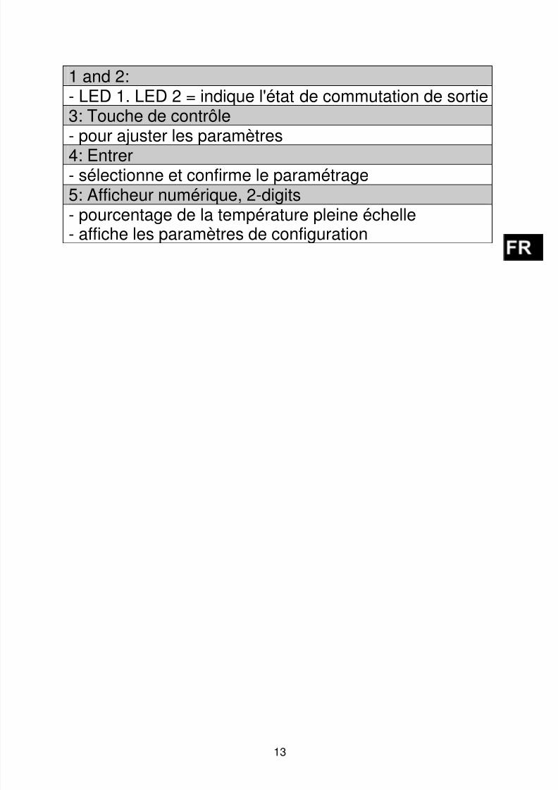
1 and 2:- LED 1. LED 2 = indique l'état de commutation de sortie3: Touche de contrôle
- pour ajuster les paramètres4: Entrer- sélectionne et confirme le paramétrage5: Afficheur numérique, 2-digits- pourcentage de la température pleine échelle- affiche les paramètres de configuration

8/13/2019 Manual sensor temperatura TW7001.pdf
http://slidepdf.com/reader/full/manual-sensor-temperatura-tw7001pdf 67/80
14
8 Menu
8.1 Menu sortie Out1
8/13/2019 Manual sensor temperatura TW7001.pdf
http://slidepdf.com/reader/full/manual-sensor-temperatura-tw7001pdf 68/80
15
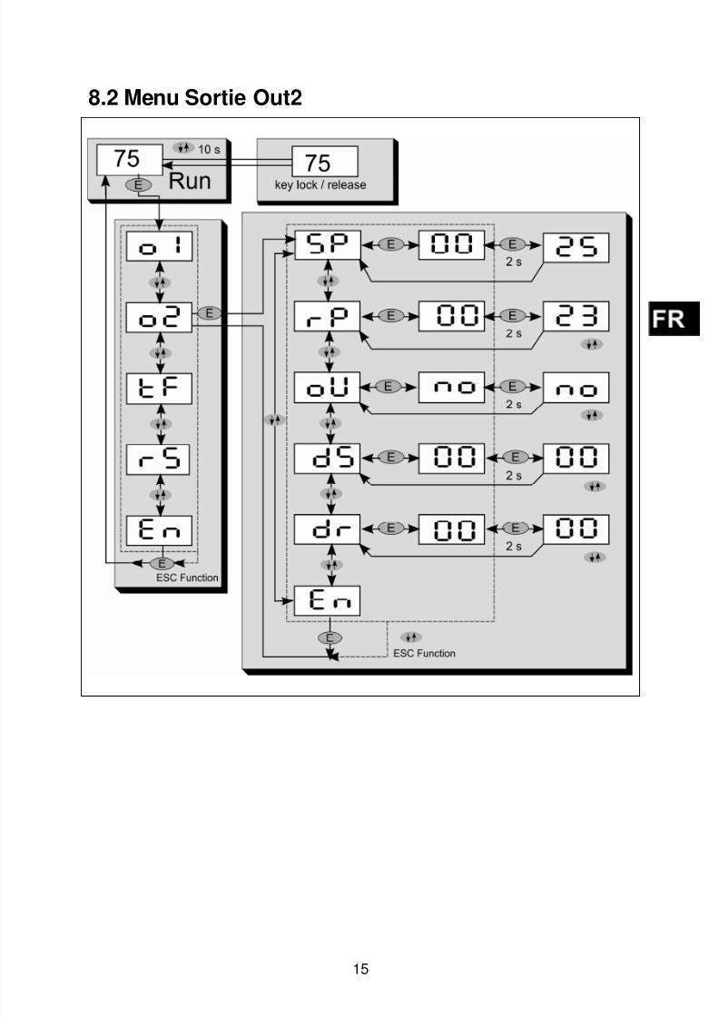
8.2 Menu Sortie Out2
8/13/2019 Manual sensor temperatura TW7001.pdf
http://slidepdf.com/reader/full/manual-sensor-temperatura-tw7001pdf 69/80

8/13/2019 Manual sensor temperatura TW7001.pdf
http://slidepdf.com/reader/full/manual-sensor-temperatura-tw7001pdf 70/80
17
9 Description des menus
9.1 Configuration
Paramètre Fonction Explication
O1 Out1 Paramètre sortie 1
O2 Out2 Paramètre sortie 2
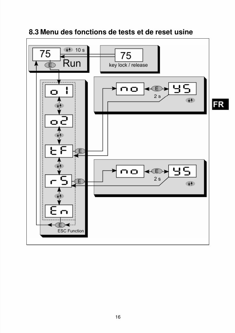
TFFonction dediagnostics
Active l’auto-diagnostic
RS
Réinitialisationdes réglagesusine
Réglages usine
9.2 Sous-menu
Paramètre Fonction Explication
SP Seuil hautLa valeur est en % de laplage de température
RP Seuil bas La valeur est en % de laplage de température≤ point de commutation
OUFonctionde sortie
NO normalement ouvert
NC normalement fermé
DSRetardseuil haut
Durée en seconde*
DR Retardseuil bas
Durée en seconde*
EN End Sortie du menu
* Maximum 9.9 sec par pas de 0.1 sec
8/13/2019 Manual sensor temperatura TW7001.pdf
http://slidepdf.com/reader/full/manual-sensor-temperatura-tw7001pdf 71/80
18
10 Opération
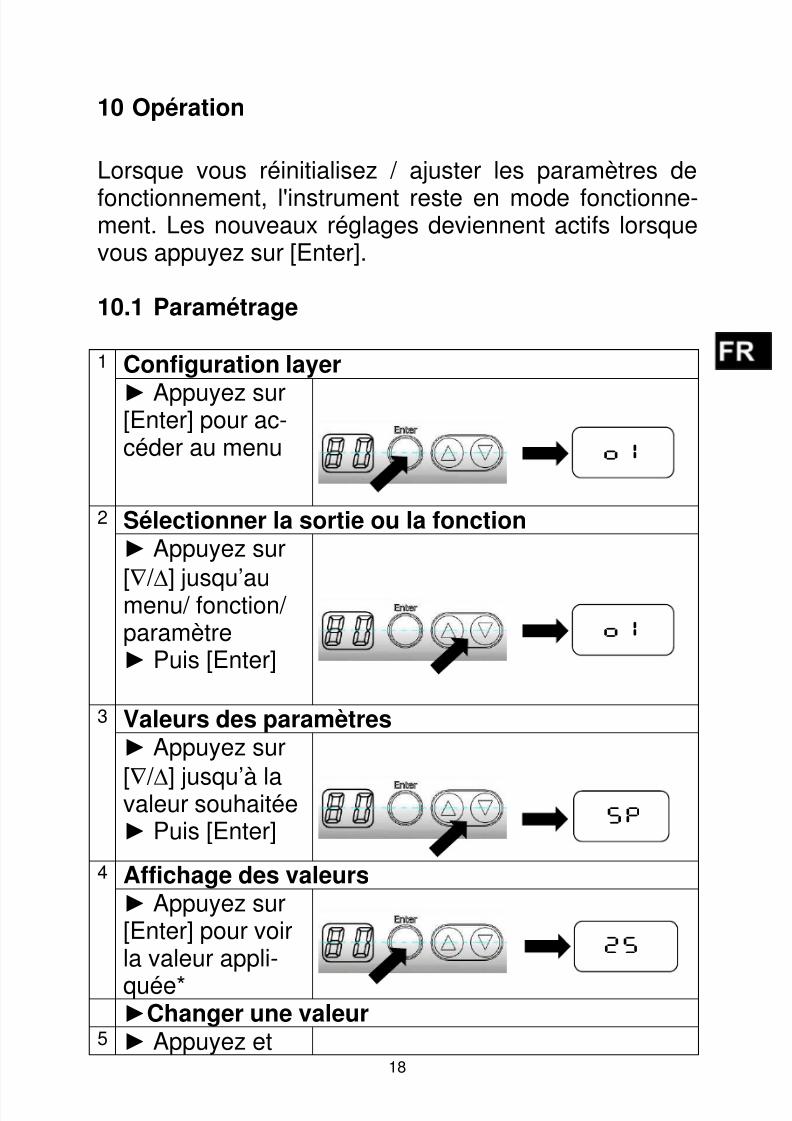
Lorsque vous réinitialisez / ajuster les paramètres de
fonctionnement, l'instrument reste en mode fonctionne-ment. Les nouveaux réglages deviennent actifs lorsquevous appuyez sur [Enter].
10.1 Paramétrage
1 Configuration layer
► Appuyez sur[Enter] pour ac-céder au menu
2 Sélectionner la sortie ou la fonction► Appuyez sur
[∇
/ ∆
] jusqu’aumenu/ fonction/paramètre► Puis [Enter]
3 Valeurs des paramètres► Appuyez sur
[∇ / ∆
] jusqu’à lavaleur souhaitée► Puis [Enter]
4 Affichage des valeurs► Appuyez sur[Enter] pour voirla valeur appli-
quée*►Changer une valeur
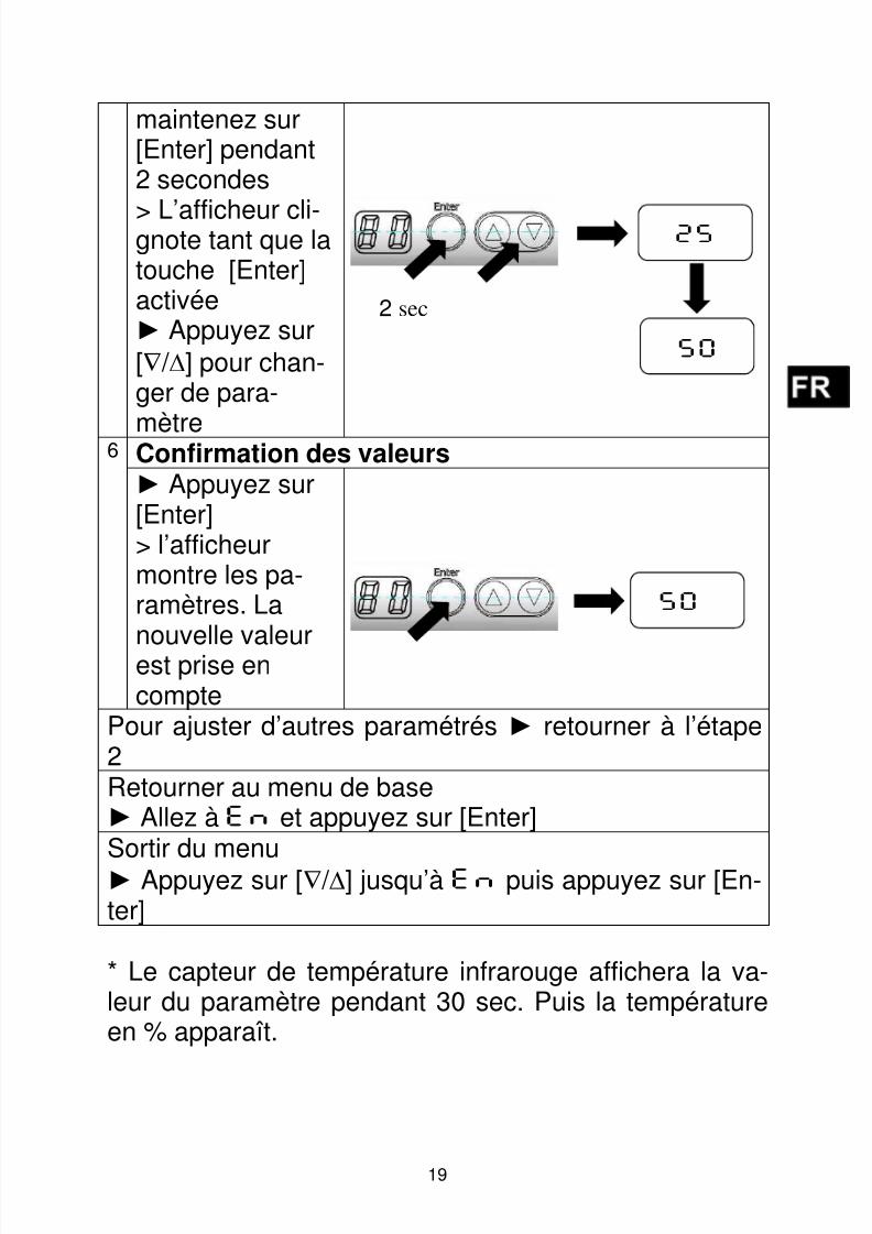
5 ► Appuyez et
O1
O1
SP
25
8/13/2019 Manual sensor temperatura TW7001.pdf
http://slidepdf.com/reader/full/manual-sensor-temperatura-tw7001pdf 72/80
19
maintenez sur[Enter] pendant2 secondes
> L’afficheur cli-gnote tant que latouche [Enter]activée► Appuyez sur
[∇ / ∆] pour chan-ger de para-
mètre6 Confirmation des valeurs► Appuyez sur[Enter]> l’afficheurmontre les pa-ramètres. La
nouvelle valeurest prise encompte
Pour ajuster d’autres paramétrés ► retourner à l’étape2Retourner au menu de base► Allez à EN et appuyez sur [Enter] Sortir du menu
► Appuyez sur [∇ / ∆] jusqu’à EN puis appuyez sur [En-ter]
* Le capteur de température infrarouge affichera la va-leur du paramètre pendant 30 sec. Puis la températureen % apparaît.
25
50
2 sec
50

8/13/2019 Manual sensor temperatura TW7001.pdf
http://slidepdf.com/reader/full/manual-sensor-temperatura-tw7001pdf 73/80
20
Appuyez sur [∇∆] simultanément pendant 10 se-condes. L’afficheur clignote une fois.
10.2 Eléments de diagnostics
L’activation de l’auto-diagnostic peut se faire soit avecles touches du détecteur ou par le signal statique (10-34V) du PIN 5.La tension doit être maintenue pendant au moins 400msec. Le détecteur simule la présence d’un objet chaudet affiche „OL”. Pour disactiver l’auto-diagnostic, une
tension <6V doit être appliquée pendant au moins 0.3sec sur le signal statiqueLa commutation de la sortie s’active une fois le délai deretard prédéfini atteint. L’auto-diagnostic vérifie les fonc-tions électriques et logiques des sorties.
L'instrument dispose d'un code de sécurité.Pour l’activer / désactiver:
Si vous appuyez sur [∇∆] simultanément et briè-vement, vous sortez du menu (ESC fonction).
Lorsque la fonction Test n’est pas utilisée, con-
nectez la borne 5 (PIN 5) au pole négatif del’alimentation. Vous pouvez aussi utilisez un con-necteur 4 fils (PIN 5 non assigné)

8/13/2019 Manual sensor temperatura TW7001.pdf
http://slidepdf.com/reader/full/manual-sensor-temperatura-tw7001pdf 74/80
21
11 Fonctionnement
A la mise sous tension, le détecteur infrarouge s’allumeet commence par un auto-diagnostic. Après environ une
demie seconde, l’équipement est opérationnel.
11.1 Paramètres de fonctionnement
Appuyez sur [Enter] et sélectionnez la sortie désirée.Appuyez sur [Enter] pour entrer dans les sous-menus.Appuyez sur [▼ / ▲] pour sélectionner le paramètre à
modifier.
Appuyez sur [Enter].> Le paramètre sélectionné s’affiche pendant 30 se-condes. Ensuite, le détecteur revient en mode RUN.
11.2 Température ambiante
La température ambiante ne doit pas dépasser 65°Cpour un bon fonctionnement. Si cette valeur est dépas-
sée, il faudra alors prévoir un système de refroidisse-ment adapté voire une plaque de protection contre lerayonnement.
11.3 Messages d’erreurs
Surcharge sur la sortie La LED de la sortie con-cernée clignote à 2 Hz
Température interne exces-sive
Affichage alternée de"OT" et de la mesure.
Défaut de branchement del’alimentation
Les deux LEDs clignotentà 2.0 Hz. Affichage de lamesure.
Tension d’alimentation≤ 7.8 V
Pas de LEDs nid’affichage.(Lorsque la tension dé-
8/13/2019 Manual sensor temperatura TW7001.pdf
http://slidepdf.com/reader/full/manual-sensor-temperatura-tw7001pdf 75/80
22
passent 8 V les commuta-tions s’activent).
Temp. en dessous du seuil
bas
Affichage de „UL“
Temp. en dessous du seuilhaut
Affichage de „OL“
12 Maintenance
12.1 Nettoyage de la lentille
Une fenêtre encrassée conduira à une mesure faussée.Un contrôle visuel de la lentille sera effectué périodi-quement et un nettoyage sera réalisé si nécessaire. Lapoussière peut être enlevée par un simple soufflage oul’utilisation d’un chiffon propre et doux ou par un papieroptique disponible dans le commerce. En cas de fort en-crassement, du liquide vaisselle et de l’eau claire pour-ront être utilisés. N’appliquez pas de pression sur la len-tille au risque de la rayer.
Assurez vous d’éteindre préalablement le détecteur in-frarouge avant de le connecter ou le déconnecter (lorsdu nettoyage) pour éviter tout risque de dommage !
13 Emballage, transport et mise à disposition
13.1 Inspection du colis
Déballez et inspectez immédiatement l’ensemble du co-lis afin de s’assurer que rien n’est manquant ou endom-magé.
Si vous constatez sur le container ou le colis des signes
de dommages externes, refusez la réception. Si celan’est pas possible, veillez faire immédiatement des ré-serves auprès de l’entreprise de transport.

8/13/2019 Manual sensor temperatura TW7001.pdf
http://slidepdf.com/reader/full/manual-sensor-temperatura-tw7001pdf 76/80
23
13.2 Emballage
L’emballage utilisé par le constructeur respectel’environnement et est recyclable. Nous vous suggérons
de conserver l'emballage pour une utilisation ultérieure,sinon s'il vous plaît veiller à ce qu'il soit éliminé d'unemanière écologiquement rationnelle

8/13/2019 Manual sensor temperatura TW7001.pdf
http://slidepdf.com/reader/full/manual-sensor-temperatura-tw7001pdf 77/80
24
13.3 Droit à la propriété
Le logiciel contient des parties de la bibliothèque avr-libc.
Portions of avr-libc are Copyright (c) 1999-2007Keith Gudger,Bjoern Haase,Steinar Haugen,Peter Yes nsen,Reinhard Jessich,Magnus Johansson,Artur Lipowski,Marek Michalkiewicz,Colin O'Flynn,Bob Paddock,Reiner Patommel,Michael Rickman,Theodore A. Roth,Juergen Schilling,Philip Soeberg,Anatoly Sokolov,Nils Kristian Strom,Michael Stumpf,Stefan Swanepoel,Eric B. Weddington,Joerg Wunsch,Dmitry Xmelkov,The Regents of the University of California.All rights reserved.
Redistribution and use in source and binary forms, with or withoutmodification, are permitted provided that the following conditions are met:
* Redistributions of source code must retain the above copyrightnotice, this list of conditions and the following disclaimer.
* Redistributions in binary form must reproduce the above copyrightnotice, this list of conditions and the following disclaimer inthe documentation and/or other materials provided with thedistribution.
* Neither the name of the copyright holders nor the names ofcontributors may be used to endorse or promote products derivedfrom this software without specific prior written permission.
THIS SOFTWARE IS PROVIDED BY THE COPYRIGHT HOLDERS AND CONTRIBUTORS "AS IS"AND ANY EXPRESS OR IMPLIED WARRANTIES, INCLUDING, BUT NOT LIMITED TO, THE
IMPLIED WARRANTIES OF MERCHANTABILITY AND FITNESS FOR A PARTICULAR PURPOSEARE DISCLAIMED. IN NO EVENT SHALL THE COPYRIGHT OWNER OR CONTRIBUTORS BELIABLE FOR ANY DIRECT, INDIRECT, INCIDENTAL, SPECIAL, EXEMPLARY, ORCONSEQUENTIAL DAMAGES (INCLUDING, BUT NOT LIMITED TO, PROCUREMENT OFSUBSTITUTE GOODS OR SERVICES; LOSS OF USE, DATA, OR PROFITS; OR BUSINESSINTERRUPTION) HOWEVER CAUSED AND ON ANY THEORY OF LIABILITY, WHETHER INCONTRACT, STRICT LIABILITY, OR TORT (INCLUDING NEGLIGENCE OR OTHERWISE)ARISING IN ANY WAY OUT OF THE USE OF THIS SOFTWARE, EVEN IF ADVISED OF THEPOSSIBILITY OF SUCH DAMAGE.

8/13/2019 Manual sensor temperatura TW7001.pdf
http://slidepdf.com/reader/full/manual-sensor-temperatura-tw7001pdf 78/80
25
14 Paramètres par défaut
Paramètre Valeurs
usine
Personnalisé
Out1
SP 25 %
RP 23 %
OU NO
DS 0 s
DR 0 s
Out2
SP 75 %
RP 73 %OU NO
DS 0 s
DR 0 s

8/13/2019 Manual sensor temperatura TW7001.pdf
http://slidepdf.com/reader/full/manual-sensor-temperatura-tw7001pdf 79/80
8/13/2019 Manual sensor temperatura TW7001.pdf
http://slidepdf.com/reader/full/manual-sensor-temperatura-tw7001pdf 80/80
ifm weltweit - ifm worldwide - ifm à l’échelle internationalehttp://www.ifm.com e-mail: [email protected]
Service-Hotline: 0800 16 16 16 4 (nur Deutschland, Mo-Fr von 7.00-18.00 Uhr)
ifm Niederlassungen • Sales offices • Agences
D ifm electronic gmbh Vertrieb Deutschland
Niederlassung Nord • 31135 Hildesheim • Tel. 0 51 21 / 76 67-0
Niederlassung West • 45128 Essen • Tel. 02 01 / 3 64 75 -0Niederlassung Mitte-West • 58511 Lüdenscheid • Tel. 0 23 51 / 43 01-0
Niederlassung Süd-West • 64646 Heppenheim • Tel. 0 62 52 / 79 05-0
Niederlassung Baden-Württemberg • 73230 Kirchheim • Tel. 0 70 21 / 80 86-0
Niederlassung Bayern • 82178 Puchheim • Tel. 0 89 / 8 00 91-0
Niederlassung Ost • 07639 Tautenhain • Tel. 0 36 601 / 771-0
ifm electronic gmbh • Friedrichstraße 1 • 45128 Essen
A ifm electronic gmbh • 1120 Wien • Tel. +43 16 17 45 00
AUS ifm efector pty ltd. • Mulgrave Vic 3170 • Tel. +61 3 00 365 088
B L ifm electronic N.V. • 1731 Zellik • Tel. +32 2 / 4 81 02 20
BR ifm electronic Ltda. • 03337-000, Sao Paulo SP • Tel. +55 11 / 2672-1730
CH ifm electronic ag • 4 624 Härkingen • Tel. +41 62 / 388 80 30
CN ifm electronic (Shanghai) Co. Ltd. • 201203 Shanghai • Tel. +86 21 / 3813 4800
CND ifm efector Canada inc. • Oakville, Ontario L6K 3V3 • Tel. +1 800-441-8246
CZ ifm electronic spol. s.r.o. • 25243 Průhonice • Tel. +420 267 990 211
DK ifm electronic a/s • 2605 BROENDBY • Tel. +45 70 20 11 08
E ifm electronic s.a. • 08820 El Prat de Llobregat • Tel. +34 93 479 30 80
F ifm electronic s.a. • 93192 Noisy-le-Grand Cedex • Tél. +33 0820 22 30 01
FIN ifm electronic oy • 00440 Helsinki • Tel . +358 75 329 5000
GB IRL ifm electronic Ltd. • Hampton, Middlesex TW12 2HD • Tel. +44 208 / 213-0000
GR ifm electronic Monoprosopi E.P.E. • 15125 Amaroussio • Tel. +30 210 / 6180090
H ifm electronic kft. • 9028 Györ • Tel. +36 96 / 518-397
I ifm electronic s.a. • 20041 Agrate-Brianza (MI) • Tel. +39 039 / 68.99.982
IL Astragal Ltd. • Azur 58001 • Tel. +972 3 -559 1660
IND ifm electronic India Branch Office • Kolhapur, 416234 • Tel. +91 231-267 27 70
J efector co., ltd. • Togane-shi, Chiba 283-0826 • Tel. +81 475-50-3003
MAL ifm electronic Pte. Ltd • 80250 Johor Bahru Johor • Tel. +60 7 / 331 5022
MEX ifm efector S. de R. L. de C. V. • Monterrey, N. L. 64630 • Tel. +52 81 8040-3535
N Sivilingeniør J. F. Knudtzen A/S • 1396 Billingstad • Tel. +47 66 / 98 33 50
NL ifm electronic b.v. • 3843 GA Harderwijk • Tel. +31 341 / 438 438
P ifm electronic s.a. • 4430-208 Vila Nova de Gaia • Tel. +351 223 / 71 71 08
PL ifm electronic Sp. z o.o. • 40-524 Katowice • Tel. +48 32-608 74 54
RA ROU ifm electronic s.r.l. • 1107 Buenos Aires • Tel. +54 11 / 5353 3436
ROK ifm electronic Ltd. • 140-884 Seoul • Tel. +82 2 / 790 5610
RP Gram Industrial, Inc. • 1770 Mantilupa City • Tel. +63 2 / 850 22 18
RUS ifm electronic • 105318 Moscow • Tel +7 495 921 44 14 o h n e v o r h e r i g e
A n k ü n d i g u n g v o r . • W e r e s e r v e t h e r i g h t t o m a k e t e
c h n i c a l a l t e r a t i o n s w i t h o u t p r i o r n o t i c e . • N o u s n o u s
r é s e r v o n s l e d r o i t d e m o d i f i e r l e s d o n n é e s t e c h n i q u
e s s a n s p r é a v i s
Related Documents