Reference Manual 00809-0100-4021, Rev JC December 2019 Rosemount ™ 3144P Temperature Transmitter with Rosemount X-well ™ Technology

Welcome message from author
This document is posted to help you gain knowledge. Please leave a comment to let me know what you think about it! Share it to your friends and learn new things together.
Transcript

Reference Manual00809-0100-4021, Rev JC
December 2019
Rosemount™ 3144P Temperature Transmitter
with Rosemount X-well™ Technology
NOTICE
Read this manual before working with the product. For personal and system safety, and for optimum product performance,ensure you thoroughly understand the contents before installing, using, or maintaining this product.
Within the United States, Emerson has two toll-free assistance numbers:
Customer Central (Technical support, quoting, and order-related questions): 1-800-999-9307 (7:00 am to 7:00 pm Central Time)
North American Response Center (Equipment service needs): 1-800-654-7768 (24 hours)
International: (952)-906-8888
CAUTION
The products described in this document are NOT designed for nuclear-qualified applications.
Using non-nuclear qualified products in applications that require nuclear-qualified hardware or products may cause inaccuratereadings.
For information on Rosemount nuclear-qualified products, contact your local Emerson Sales Representative.
WARNING
Failure to follow these installation guidelines could result in death or serious injury.
Ensure only qualified personnel perform installation or service.
Electrical shock could cause death or serious injury.
Use extreme caution when making contact with the leads and terminals.
Explosions could result in death or serious injury.
Do not remove the connection head cover in explosive atmospheres when the circuit is live.
Before powering a FOUNDATION™ Fieldbus segment in an explosive atmosphere, ensure the instruments in the loop are installed inaccordance with intrinsically safe or non-incendive field wiring practices.
Verify that the operating atmosphere of the transmitter is consistent with the appropriate hazardous locations certifications.
All connection head covers must be fully engaged to meet explosion-proof requirements.
Process leaks could result in death or serious injury.
Do not remove the thermowell while in operation.
Install and tighten thermowells or sensors before applying pressure.
Physical access
Unauthorized personnel may potentially cause significant damage to and/or misconfiguration of end users’ equipment. This couldbe intentional or unintentional and needs to be protected against.
Physical security is an important part of any security program and fundamental to protecting your system. Restrict physical accessby unauthorized personnel to protect end users’ assets. This is true for all systems used within the facility.
2
Contents
Chapter 1 Introduction.................................................................................................................. 51.1 Using this manual............................................................................................................................. 5
1.2 Rosemount 3144P revisions............................................................................................................. 6
1.3 Confirm HART revision capability....................................................................................................10
Chapter 2 Installation...................................................................................................................112.1 Installation considerations..............................................................................................................11
2.2 Commissioning.............................................................................................................................. 13
2.3 Mounting....................................................................................................................................... 16
2.4 Installation..................................................................................................................................... 17
2.5 Wiring............................................................................................................................................ 23
2.6 Foundation Fieldbus....................................................................................................................... 27
2.7 Power supply.................................................................................................................................. 28
2.8 Grounding...................................................................................................................................... 29
2.9 Wire and apply power.....................................................................................................................32
Chapter 3 HART Commissioning...................................................................................................333.1 Overview........................................................................................................................................ 33
3.2 Confirm HART revision capability....................................................................................................33
3.3 Safety messages............................................................................................................................. 34
3.4 Field Communicator....................................................................................................................... 34
3.5 Review configuration data.............................................................................................................. 44
3.6 Check output..................................................................................................................................44
3.7 Configuration................................................................................................................................. 44
3.8 Rosemount X-well Technology configuration................................................................................. 99
3.9 Device output configuration.........................................................................................................102
3.10 Device information.....................................................................................................................104
3.11 Measurement filtering................................................................................................................106
3.12 Diagnostics and service.............................................................................................................. 108
3.13 Multidrop communication..........................................................................................................109
3.14 Use with the HART Tri-Loop........................................................................................................ 110
3.15 Configure Thermocouple Degradation in guided setup.............................................................. 113
3.16 Configure Thermocouple Degradation in manual setup............................................................. 118
3.17 Active Thermocouple Degradation Alerts................................................................................... 123
3.18 Minimum/maximum tracking diagnostic....................................................................................128
3.19 Calibration..................................................................................................................................136
3.20 Trim the transmitter................................................................................................................... 137
3.21 Output trim or scaled output trim.............................................................................................. 147
Reference Manual Contents00809-0100-4021 December 2019
Reference Manual iii
3.22 Troubleshooting.........................................................................................................................148
Chapter 4 FOUNDATION Fieldbus Configuration......................................................................... 1574.1 Overview...................................................................................................................................... 157
4.2 Safety messages...........................................................................................................................157
4.3 Device description........................................................................................................................157
4.4 Node address............................................................................................................................... 158
4.5 Modes.......................................................................................................................................... 158
4.6 Link Active Scheduler (LAS)...........................................................................................................159
4.7 Capabilities...................................................................................................................................159
4.8 FOUNDATION Fieldbus function blocks............................................................................................ 160
4.9 Resource block............................................................................................................................. 162
4.10 Analog Input (AI)........................................................................................................................ 175
4.11 Operation...................................................................................................................................182
4.12 Troubleshooting guides..............................................................................................................188
Chapter 5 Operation and maintenance.......................................................................................1935.1 Safety messages...........................................................................................................................193
5.2 Maintenance................................................................................................................................ 193
5.3 Return of materials....................................................................................................................... 195
Chapter 6 Safety Instrumented Systems (SIS) requirements....................................................... 1976.1 SIS certification.............................................................................................................................197
6.2 Safety certified identification........................................................................................................197
6.3 Installation................................................................................................................................... 197
6.4 Configuration............................................................................................................................... 198
6.5 Operation and maintenance.........................................................................................................200
6.6 Specifications............................................................................................................................... 201
6.7 Spare parts................................................................................................................................... 202
Appendix A Reference data........................................................................................................... 203A.1 Product Certifications...................................................................................................................203
A.2 Ordering Information, Specifications, and Drawings.................................................................... 203
Contents Reference ManualDecember 2019 00809-0100-4021
iv Rosemount 3144P
1 Introduction
1.1 Using this manualThe sections in this manual provide information on installing, operating, and maintainingthe Rosemount™ 3144P Temperature Transmitter. The sections are organized as follows:
• Installation contains mechanical and electrical installation instructions.
• HART Commissioning contains techniques for properly commissioning the device.
• FOUNDATION Fieldbus Configuration provides instruction on commissioning andoperating the Rosemount 3144P Transmitter. This chapter also includes informationon software functions, configuration parameters, and online variables.
• Operation and maintenance contains operation and maintenance techniques.
• Safety Instrumented Systems (SIS) Requirements provides identification, installation,configuration, operation and maintenance, and inspection information for SafetyInstrumented Systems.
• Reference Data supplies reference and specification data, as well as orderinginformation and contains intrinsic safety approval information, European ATEXdirective information, and approval drawings.
1.1.1 TransmitterIndustry-leading temperature transmitter delivers unmatched field reliability andinnovative process measurement solutions:
• Rosemount X-Well™ Technology provides a Complete Point Solution™ for accuratelymeasuring process temperature in monitoring applications without the requirement ofa thermowell or process penetration
• Superior accuracy and stability
• Dual and single sensor capability with universal sensor inputs (RTD, T/C, mV, ohms)
• Comprehensive sensor and process diagnostics offering
• IEC 61508 safety certification
• Dual-compartment housing
• Large LCD display
• Selectable HART® Revision (5 and 7) or FOUNDATION Fieldbus protocols
Improve efficiency with Best-in-Class product specifications and capabilities:
• Reduce maintenance and improve performance with industry leading accuracy andstability.
• Improve measurement accuracy by 75 percent with Transmitter-Sensor Matching.
• Ensure process health with system alerts and easy-to-use Device Dashboards.
Reference Manual Introduction00809-0100-4021 December 2019
Reference Manual 5
• Easily check device status and values on local LCD display with large percent rangegraph.
• Achieve high reliability and installation ease with the industry's most rugged dualcompartment design.
Optimize measurement reliability with diagnostics designed for any protocol on any hostsystem.
• Thermocouple Degradation Diagnostic monitors the health of a thermocouple loop,enabling preventative maintenance.
• Minimum and Maximum Temperature Tracking tracks and records temperatureextremes of the process sensors and the ambient environment.
• Sensor Drift Alert detects sensor drift and alerts you.
• The Hot Backup™ feature provides temperature measurement redundancy.
Refer to the following literature for a full range of compatible connection heads, sensors,and thermowells provided by Emerson:
• Rosemount Volume 1 Temperature Sensors and Accessories Product Data Sheet
• Rosemount DIN-Style Temperature Sensors and Thermowells (Metric) Product DataSheet
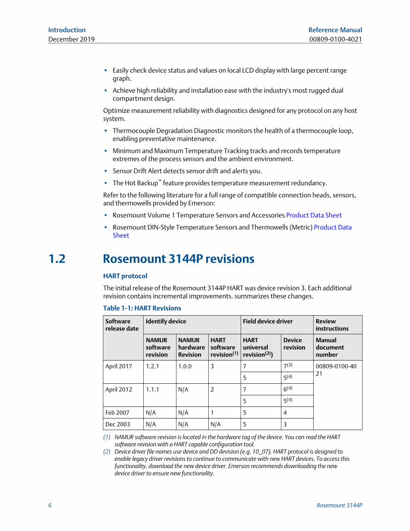
1.2 Rosemount 3144P revisionsHART protocol
The initial release of the Rosemount 3144P HART was device revision 3. Each additionalrevision contains incremental improvements. summarizes these changes.
Table 1-1: HART Revisions
Softwarerelease date
Identify device Field device driver Reviewinstructions
NAMURsoftwarerevision
NAMURhardwareRevision
HARTsoftwarerevision(1)
HARTuniversalrevision(2))
Devicerevision
Manualdocumentnumber
April 2017 1.2.1 1.0.0 3 7 7(3) 00809-0100-4021
5 5(4)
April 2012 1.1.1 N/A 2 7 6(4)
5 5(4)
Feb 2007 N/A N/A 1 5 4
Dec 2003 N/A N/A N/A 5 3
(1) NAMUR software revision is located in the hardware tag of the device. You can read the HARTsoftware revision with a HART capable configuration tool.
(2) Device driver file names use device and DD devision (e.g. 10_07). HART protocol is designed toenable legacy driver revisions to continue to communicate with new HART devices. To access thisfunctionality, download the new device driver. Emerson recommends downloading the newdevice driver to ensure new functionality.
Introduction Reference ManualDecember 2019 00809-0100-4021
6 Rosemount 3144P
(3) Rosemount X-well sensor type.(4) HART Revision 5 and 7 selectable, Thermocouple Degradation Diagnostic, Min/Max Tracking.
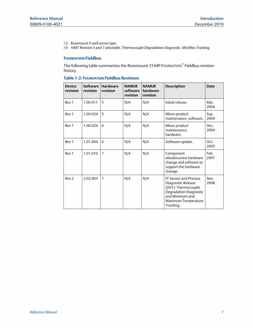
FOUNDATION Fieldbus
The following table summarizes the Rosemount 3144P FOUNDATION™ Fieldbus revisionhistory.
Table 1-2: FOUNDATION Fieldbus Revisions
Devicerevision
Softwarerevision
Hardwarerevision
NAMURsoftwarerevision
NAMURhardwarerevision
Description Date
Rev 1 1.00.011 5 N/A N/A Initial release. Mar.2004
Rev 1 1.00.024 5 N/A N/A Minor productmaintenance, software.
Sep.2004
Rev 1 1.00.024 6 N/A N/A Minor productmaintenance,hardware.
Dec.2004
Rev 1 1.01.004 6 N/A N/A Software update. Oct.2005
Rev 1 1.01.010 7 N/A N/A Componentobsolescence hardwarechange and software tosupport the hardwarechange.
Feb.2007
Rev 2 2.02.003 7 N/A N/A FF Sensor and ProcessDiagnostic Release(D01): ThermocoupleDegradation Diagnosticand Minimum andMaximum TemperatureTracking.
Nov.2008
Reference Manual Introduction00809-0100-4021 December 2019
Reference Manual 7
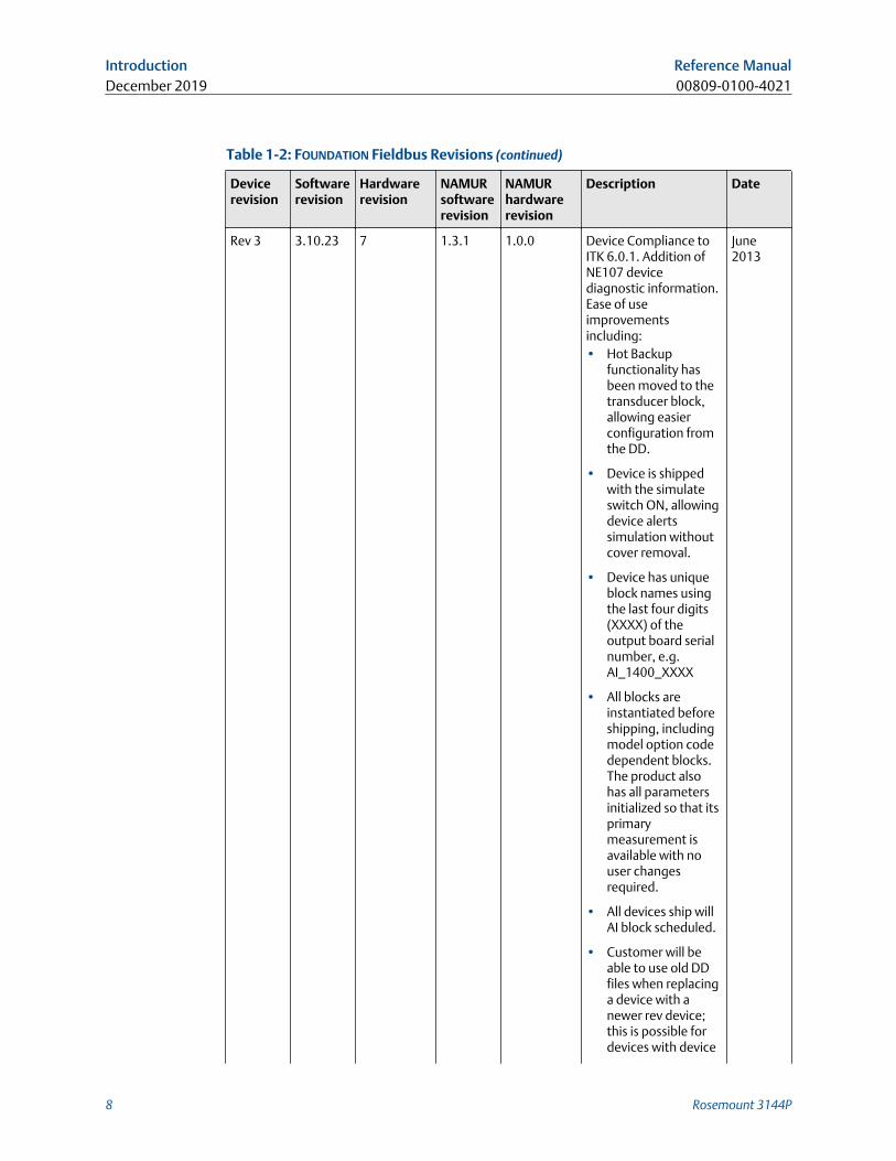
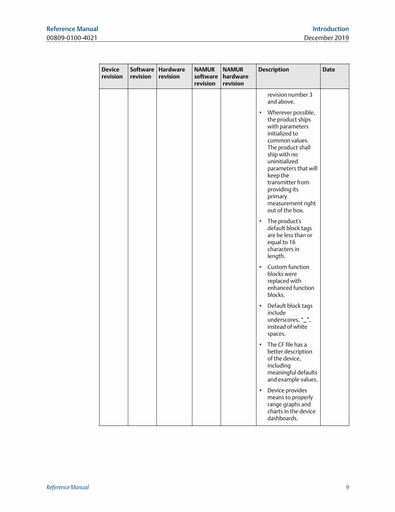
Table 1-2: FOUNDATION Fieldbus Revisions (continued)
Devicerevision
Softwarerevision
Hardwarerevision
NAMURsoftwarerevision
NAMURhardwarerevision
Description Date
Rev 3 3.10.23 7 1.3.1 1.0.0 Device Compliance toITK 6.0.1. Addition ofNE107 devicediagnostic information.Ease of useimprovementsincluding:• Hot Backup
functionality hasbeen moved to thetransducer block,allowing easierconfiguration fromthe DD.
• Device is shippedwith the simulateswitch ON, allowingdevice alertssimulation withoutcover removal.
• Device has uniqueblock names usingthe last four digits(XXXX) of theoutput board serialnumber, e.g.AI_1400_XXXX
• All blocks areinstantiated beforeshipping, includingmodel option codedependent blocks.The product alsohas all parametersinitialized so that itsprimarymeasurement isavailable with nouser changesrequired.
• All devices ship willAI block scheduled.
• Customer will beable to use old DDfiles when replacinga device with anewer rev device;this is possible fordevices with device
June2013
Introduction Reference ManualDecember 2019 00809-0100-4021
8 Rosemount 3144P
Devicerevision
Softwarerevision
Hardwarerevision
NAMURsoftwarerevision
NAMURhardwarerevision
Description Date
revision number 3and above.
• Wherever possible,the product shipswith parametersinitialized tocommon values.The product shallship with nouninitializedparameters that willkeep thetransmitter fromproviding itsprimarymeasurement rightout of the box.
• The product'sdefault block tagsare be less than orequal to 16characters inlength.
• Custom functionblocks werereplaced withenhanced functionblocks.
• Default block tagsincludeunderscores, “_”,instead of whitespaces.
• The CF file has abetter descriptionof the device,includingmeaningful defaultsand example values.
• Device providesmeans to properlyrange graphs andcharts in the devicedashboards.
Reference Manual Introduction00809-0100-4021 December 2019
Reference Manual 9
1.3 Confirm HART revision capabilityConfirm the HART capability of the system devices prior to transmitter installation.
Prerequisites
If using HART based control or asset management systems, confirm the HART capability ofthose systems prior to transmitter installation. Not all systems are capable ofcommunicating with HART Revision 7protocol. You can configure the transmitter foreither HART Revision 5 or Revision 7.
Switch HART revision mode
If the HART configuration tool is not capable of communicating with HART Revision 7, thetransmitter will load a Generic Menu with limited capability. The following procedures willswitch the HART revision mode from the Generic Menu.
Procedure
Select Manual Setup → Device Information → Identification → Message.
a) To change to HART Revision 5, enter HART5 in the Message field.
b) To change to HART Revision 7, enter HART7 in the Message field.
Introduction Reference ManualDecember 2019 00809-0100-4021
10 Rosemount 3144P
2 Installation
2.1 Installation considerations
2.1.1 GeneralElectrical temperature sensors, such as resistance temperature detectors (RTDs) andthermocouples (T/Cs), produce low-level signals proportional to temperature. TheRosemount X-well™ 3144P Temperature Transmitter converts low-level signals to HART®
or FOUNDATION™ Fieldbus and then transmits the signals to the control system via twopower/signal wires.
2.1.2 ElectricalProper electrical installation is essential to prevent errors due to sensor lead resistance andelectrical noise. For HART communications, the current loop must have between 250 and1100 ohms resistance. Refer to for sensor and current loop connections. FoundationFieldbus devices must have proper termination and power conditioning for reliableoperation. Shielded cables must be used for Foundation Fieldbus and may only begrounded in one place.
2.1.3 Temperature effectsTemperature effects
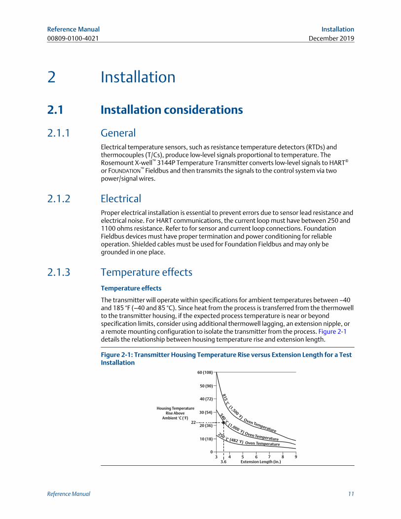
The transmitter will operate within specifications for ambient temperatures between –40and 185 °F (–40 and 85 °C). Since heat from the process is transferred from the thermowellto the transmitter housing, if the expected process temperature is near or beyondspecification limits, consider using additional thermowell lagging, an extension nipple, ora remote mounting configuration to isolate the transmitter from the process. Figure 2-1details the relationship between housing temperature rise and extension length.
Figure 2-1: Transmitter Housing Temperature Rise versus Extension Length for a TestInstallation
(1,500 °F) Temperature
Oven(1,000 °F) Temperature
Oven(482 °F) TemperatureOven
Housing TemperatureRise Above
Ambient °C (°F)
60 (108)
50 (90)
40 (72)
0
30 (54)
20 (36)
10 (18)
3 4 5 6 7 8 9 Extension Length (in.)
81
5 °C
250 °C
540 °C 22
3.6
Reference Manual Installation00809-0100-4021 December 2019
Reference Manual 11
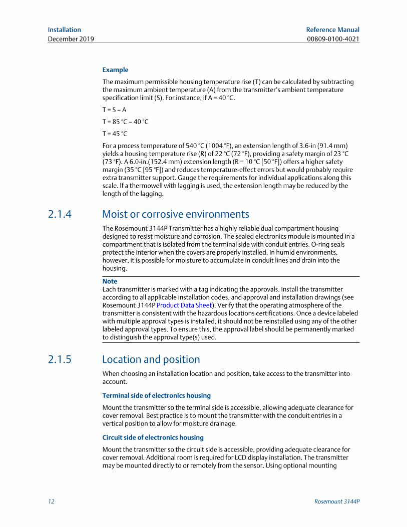
Example
The maximum permissible housing temperature rise (T) can be calculated by subtractingthe maximum ambient temperature (A) from the transmitter’s ambient temperaturespecification limit (S). For instance, if A = 40 °C.
T = S – A
T = 85 °C – 40 °C
T = 45 °C
For a process temperature of 540 °C (1004 °F), an extension length of 3.6-in (91.4 mm)yields a housing temperature rise (R) of 22 °C (72 °F), providing a safety margin of 23 °C(73 °F). A 6.0-in.(152.4 mm) extension length (R = 10 °C [50 °F]) offers a higher safetymargin (35 °C [95 °F]) and reduces temperature-effect errors but would probably requireextra transmitter support. Gauge the requirements for individual applications along thisscale. If a thermowell with lagging is used, the extension length may be reduced by thelength of the lagging.
2.1.4 Moist or corrosive environmentsThe Rosemount 3144P Transmitter has a highly reliable dual compartment housingdesigned to resist moisture and corrosion. The sealed electronics module is mounted in acompartment that is isolated from the terminal side with conduit entries. O-ring sealsprotect the interior when the covers are properly installed. In humid environments,however, it is possible for moisture to accumulate in conduit lines and drain into thehousing.
NoteEach transmitter is marked with a tag indicating the approvals. Install the transmitteraccording to all applicable installation codes, and approval and installation drawings (seeRosemount 3144P Product Data Sheet). Verify that the operating atmosphere of thetransmitter is consistent with the hazardous locations certifications. Once a device labeledwith multiple approval types is installed, it should not be reinstalled using any of the otherlabeled approval types. To ensure this, the approval label should be permanently markedto distinguish the approval type(s) used.
2.1.5 Location and positionWhen choosing an installation location and position, take access to the transmitter intoaccount.
Terminal side of electronics housing
Mount the transmitter so the terminal side is accessible, allowing adequate clearance forcover removal. Best practice is to mount the transmitter with the conduit entries in avertical position to allow for moisture drainage.
Circuit side of electronics housing
Mount the transmitter so the circuit side is accessible, providing adequate clearance forcover removal. Additional room is required for LCD display installation. The transmittermay be mounted directly to or remotely from the sensor. Using optional mounting
Installation Reference ManualDecember 2019 00809-0100-4021
12 Rosemount 3144P
brackets, the transmitter may be mounted to a flat surface or a 2.0-in. (50.8 mm)diameter pipe (see Mounting).
2.1.6 Software compatibilityReplacement transmitters may contain revised software that is not fully compatible withthe existing software. The latest device descriptors (DD) are available with new FieldCommunicators or they can be loaded into existing communicators at any EmersonService Center or via the Easy Upgrade process. For more information on upgrading a FieldCommunicator, see HART Commissioning.
To download new device drivers, visit Emerson.com/Rosemount/Device-Install-Kits.
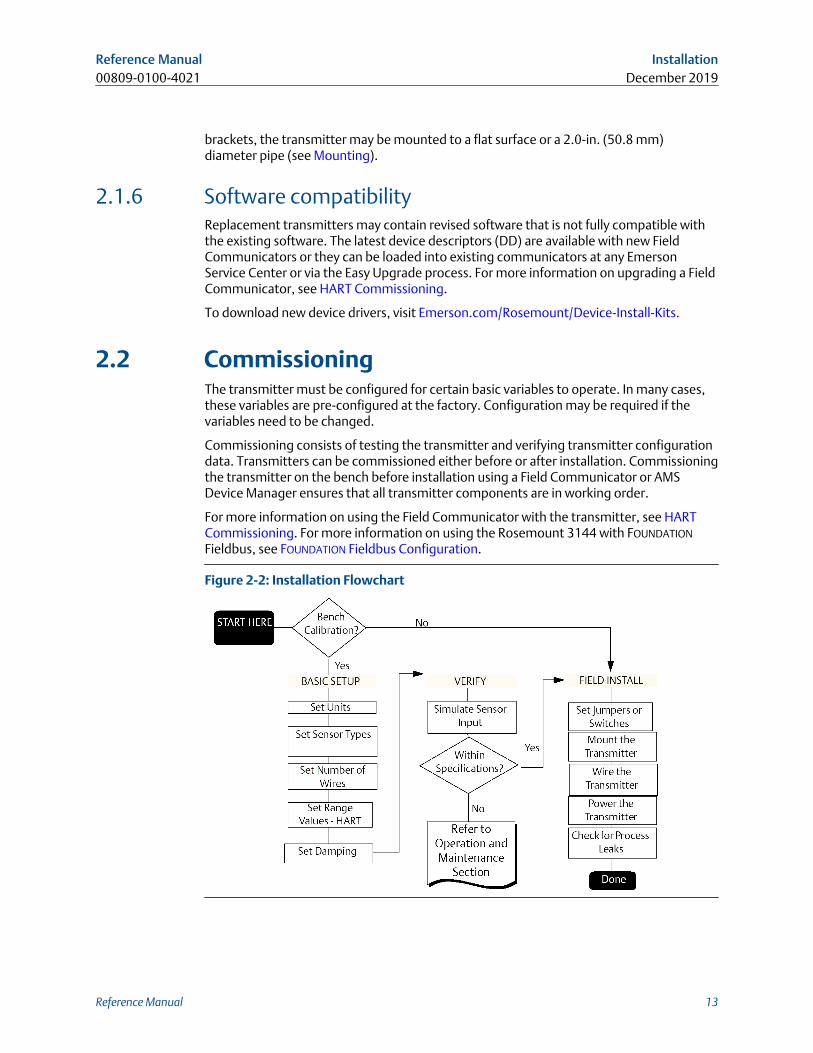
2.2 CommissioningThe transmitter must be configured for certain basic variables to operate. In many cases,these variables are pre-configured at the factory. Configuration may be required if thevariables need to be changed.
Commissioning consists of testing the transmitter and verifying transmitter configurationdata. Transmitters can be commissioned either before or after installation. Commissioningthe transmitter on the bench before installation using a Field Communicator or AMSDevice Manager ensures that all transmitter components are in working order.
For more information on using the Field Communicator with the transmitter, see HARTCommissioning. For more information on using the Rosemount 3144 with FOUNDATION
Fieldbus, see FOUNDATION Fieldbus Configuration.
Figure 2-2: Installation Flowchart
Reference Manual Installation00809-0100-4021 December 2019
Reference Manual 13
2.2.1 Setting the loop to manualSet the process application loop to manual when sending or requesting data that woulddisrupt the loop or change the output of the transmitter. The Field Communicator or AMSDevice Manager will prompt to set the loop to manual, when necessary. Acknowledgingthe prompt does not set the loop to manual, it is only a reminder. Setting the loop tomanual is a separate operation.
2.2.2 Set switchesThe security and simulate switches are located on the top center of the electronicsmodule.
NoteThe factory ships the simulate switch in the "ON" position.
HART
Set the switches without an LCD display
Procedure
1. If the transmitter is installed in a loop, set the loop to manual mode and disconnectthe power.
2. Remove the housing cover on the electronics side of the transmitter. Do notremove the transmitter cover in explosive atmospheres with a live circuit.
3. Set the switches to the desired position (see Figure 2-3).
4. Replace the transmitter cover. Both transmitter covers must be fully engaged tomeet explosion-proof requirements.
5. Apply power and set the loop to automatic mode.
Set the switches with an LCD display
Procedure
1. If the transmitter is installed in a loop, set the loop to manual mode and disconnectthe power.
2. Remove the housing cover on the electronics side of the transmitter. Do notremove the transmitter cover in explosive atmospheres with a live circuit.
3. Unscrew the LCD display screws and gently slide the meter straight off.
4. Set the switches to the desired position (see Figure 2-3).
5. Gently slide the LCD display back into place, taking extra precautions with the 10pin connection.
6. Replace and tighten the LCD display screws to secure the LCD display.
7. Replace the transmitter cover. Both transmitter covers must be fully engaged tomeet explosion-proof requirements.
8. Apply power and set the loop to automatic mode.
Installation Reference ManualDecember 2019 00809-0100-4021
14 Rosemount 3144P
FOUNDATION FieldbusSet switches without LCD display
Procedure
1. Set the loop to Out-of-Service (OOS) mode (if applicable) and disconnect thepower.
2. Remove the electronics housing cover.
3. Set the switches to the desired position.
4. Reattach housing cover.
5. Apply power and set the loop to in-service mode.
Set switches with LCD display
Procedure
1. Set the loop to OOS (if applicable) and disconnect the power.
2. Remove the housing cover on the electronics side of the transmitter.
3. Unscrew the LCD display screws and gently pull the meter straight off.
4. Set the switches to the desired position.
5. Replace and tighten the LCD display screws to secure the LCD display.
6. Replace the transmitter cover.
7. Apply power and set the loop to In-service mode.
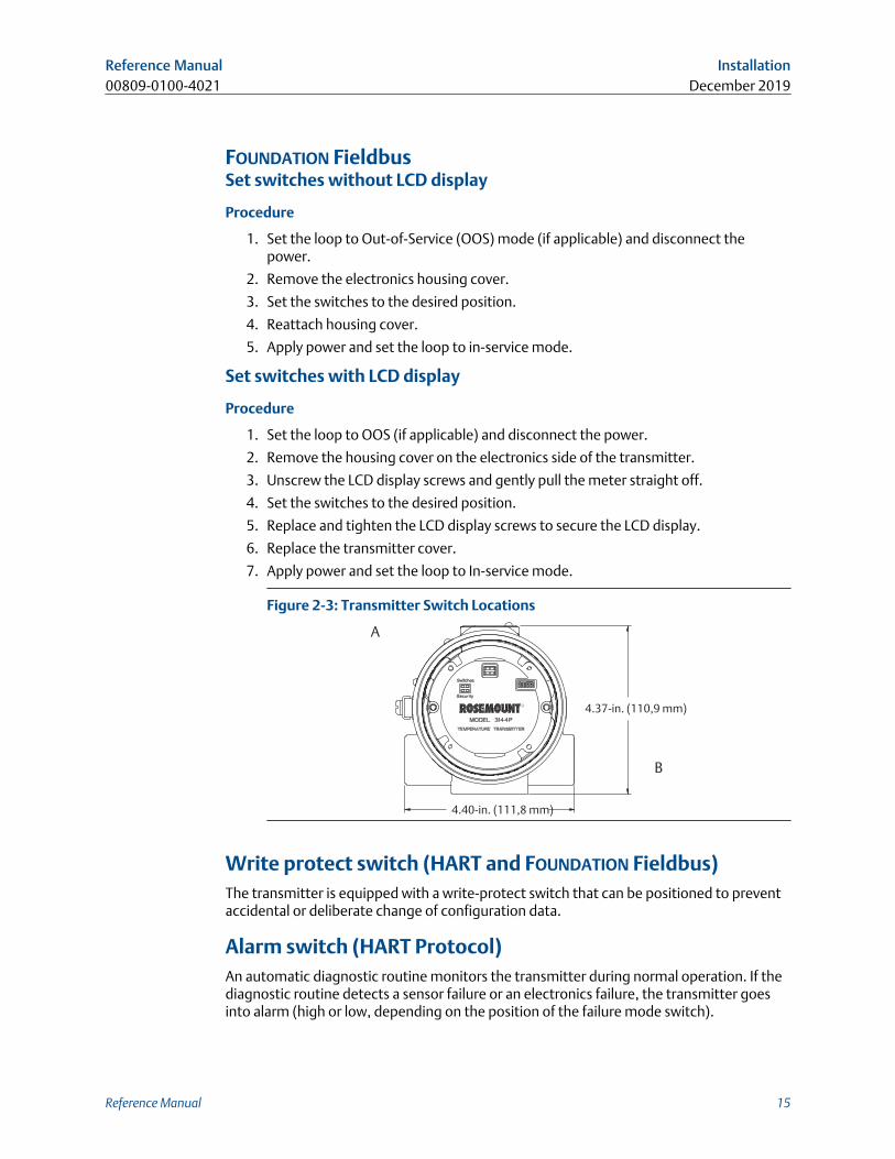
Figure 2-3: Transmitter Switch Locations
4.37-in. (110,9 mm)
4.40-in. (111,8 mm)
A
B
Write protect switch (HART and FOUNDATION Fieldbus)The transmitter is equipped with a write-protect switch that can be positioned to preventaccidental or deliberate change of configuration data.
Alarm switch (HART Protocol)An automatic diagnostic routine monitors the transmitter during normal operation. If thediagnostic routine detects a sensor failure or an electronics failure, the transmitter goesinto alarm (high or low, depending on the position of the failure mode switch).
Reference Manual Installation00809-0100-4021 December 2019
Reference Manual 15
The analog alarm and saturation values used by the transmitter depend on whether it isconfigured to standard or NAMUR-compliant operation. These values are also custom-configurable in both the factory and the field using the HART Communications. The limitsare:
• 21.0 ≤ I ≤ 23 for high alarm
• 20.5 ≤ I ≤ 20.9 for high saturation
• 3.70 ≤ I ≤ 3.90 for low saturation
• 3.50 ≤ I ≤ 3.75 for low alarm
NoteA 0.1 mA separation between low saturation and low alarm is required.
Table 2-1: Values for Standard and NAMUR Operation
Standard operation (factory default) NAMUR-compliant operation
Fail high 21.75 mA ≤ I Fail high 21.0 mA ≤ I
High saturation 20.5 mA High saturation 20.5 mA
Low saturation 3.9 mA Low saturation 3.8 mA
Fail low I ≤ 3.75 mA Fail low I ≤ 3.6 mA
Simulate switch (FOUNDATION Fieldbus)Simulate switch is used to replace the channel value coming from the sensor transducerblock. For testing purposes, it manually simulates the output of the analog input block to adesired value.
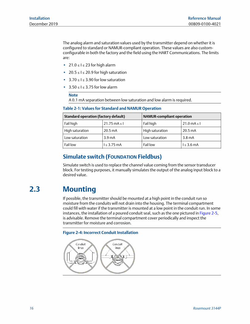
2.3 MountingIf possible, the transmitter should be mounted at a high point in the conduit run somoisture from the conduits will not drain into the housing. The terminal compartmentcould fill with water if the transmitter is mounted at a low point in the conduit run. In someinstances, the installation of a poured conduit seal, such as the one pictured in Figure 2-5,is advisable. Remove the terminal compartment cover periodically and inspect thetransmitter for moisture and corrosion.
Figure 2-4: Incorrect Conduit Installation
Installation Reference ManualDecember 2019 00809-0100-4021
16 Rosemount 3144P
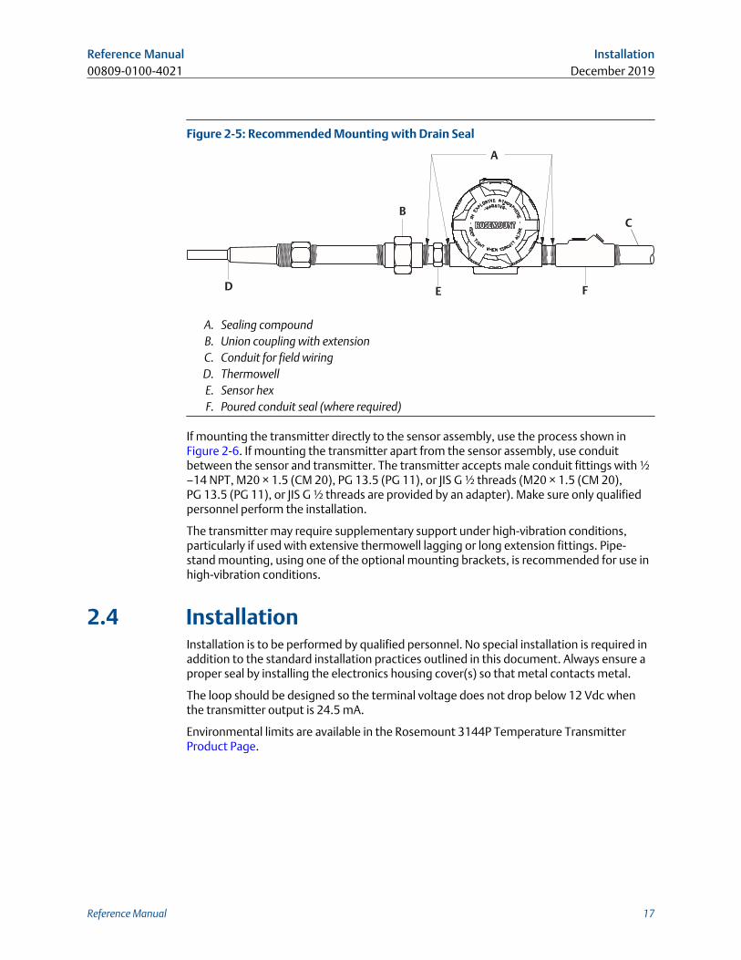
Figure 2-5: Recommended Mounting with Drain Seal
A
D
B
E F
C
A. Sealing compoundB. Union coupling with extensionC. Conduit for field wiringD. ThermowellE. Sensor hexF. Poured conduit seal (where required)
If mounting the transmitter directly to the sensor assembly, use the process shown inFigure 2-6. If mounting the transmitter apart from the sensor assembly, use conduitbetween the sensor and transmitter. The transmitter accepts male conduit fittings with ½–14 NPT, M20 × 1.5 (CM 20), PG 13.5 (PG 11), or JIS G ½ threads (M20 × 1.5 (CM 20),PG 13.5 (PG 11), or JIS G ½ threads are provided by an adapter). Make sure only qualifiedpersonnel perform the installation.
The transmitter may require supplementary support under high-vibration conditions,particularly if used with extensive thermowell lagging or long extension fittings. Pipe-stand mounting, using one of the optional mounting brackets, is recommended for use inhigh-vibration conditions.
2.4 InstallationInstallation is to be performed by qualified personnel. No special installation is required inaddition to the standard installation practices outlined in this document. Always ensure aproper seal by installing the electronics housing cover(s) so that metal contacts metal.
The loop should be designed so the terminal voltage does not drop below 12 Vdc whenthe transmitter output is 24.5 mA.
Environmental limits are available in the Rosemount 3144P Temperature TransmitterProduct Page.
Reference Manual Installation00809-0100-4021 December 2019
Reference Manual 17
2.4.1 Typical North American installation
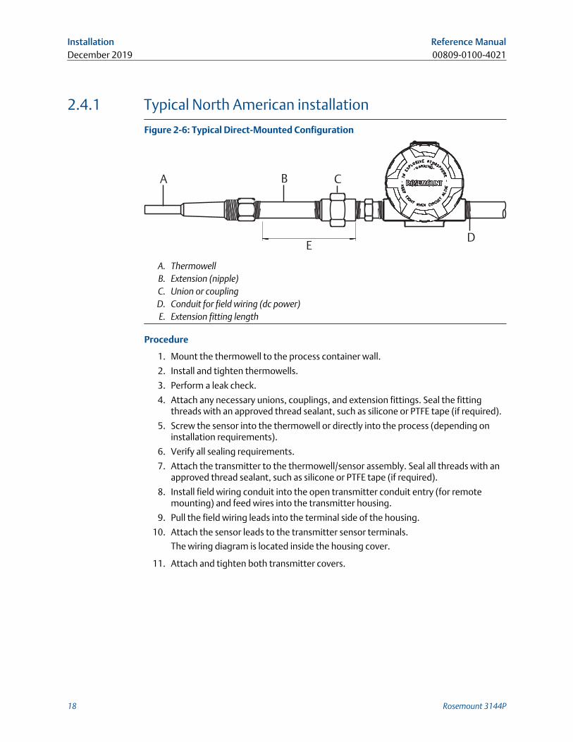
Figure 2-6: Typical Direct-Mounted Configuration
A B C
ED
A. ThermowellB. Extension (nipple)C. Union or couplingD. Conduit for field wiring (dc power)E. Extension fitting length
Procedure
1. Mount the thermowell to the process container wall.
2. Install and tighten thermowells.
3. Perform a leak check.
4. Attach any necessary unions, couplings, and extension fittings. Seal the fittingthreads with an approved thread sealant, such as silicone or PTFE tape (if required).
5. Screw the sensor into the thermowell or directly into the process (depending oninstallation requirements).
6. Verify all sealing requirements.
7. Attach the transmitter to the thermowell/sensor assembly. Seal all threads with anapproved thread sealant, such as silicone or PTFE tape (if required).
8. Install field wiring conduit into the open transmitter conduit entry (for remotemounting) and feed wires into the transmitter housing.
9. Pull the field wiring leads into the terminal side of the housing.
10. Attach the sensor leads to the transmitter sensor terminals.
The wiring diagram is located inside the housing cover.
11. Attach and tighten both transmitter covers.
Installation Reference ManualDecember 2019 00809-0100-4021
18 Rosemount 3144P
2.4.2 Typical European installation
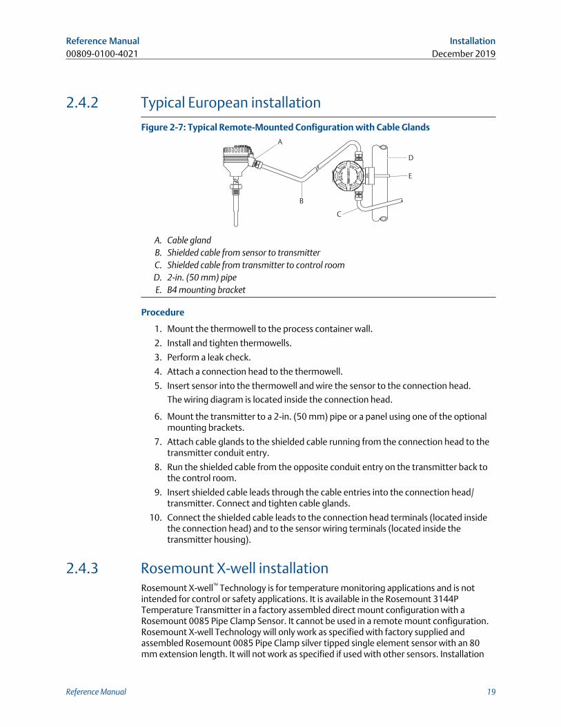
Figure 2-7: Typical Remote-Mounted Configuration with Cable Glands
A
B
C
D
E
A. Cable glandB. Shielded cable from sensor to transmitterC. Shielded cable from transmitter to control roomD. 2-in. (50 mm) pipeE. B4 mounting bracket
Procedure
1. Mount the thermowell to the process container wall.
2. Install and tighten thermowells.
3. Perform a leak check.
4. Attach a connection head to the thermowell.
5. Insert sensor into the thermowell and wire the sensor to the connection head.
The wiring diagram is located inside the connection head.
6. Mount the transmitter to a 2-in. (50 mm) pipe or a panel using one of the optionalmounting brackets.
7. Attach cable glands to the shielded cable running from the connection head to thetransmitter conduit entry.
8. Run the shielded cable from the opposite conduit entry on the transmitter back tothe control room.
9. Insert shielded cable leads through the cable entries into the connection head/transmitter. Connect and tighten cable glands.
10. Connect the shielded cable leads to the connection head terminals (located insidethe connection head) and to the sensor wiring terminals (located inside thetransmitter housing).
2.4.3 Rosemount X-well installationRosemount X-well™ Technology is for temperature monitoring applications and is notintended for control or safety applications. It is available in the Rosemount 3144PTemperature Transmitter in a factory assembled direct mount configuration with aRosemount 0085 Pipe Clamp Sensor. It cannot be used in a remote mount configuration.Rosemount X-well Technology will only work as specified with factory supplied andassembled Rosemount 0085 Pipe Clamp silver tipped single element sensor with an 80mm extension length. It will not work as specified if used with other sensors. Installation
Reference Manual Installation00809-0100-4021 December 2019
Reference Manual 19
and use of incorrect sensor will result in inaccurate process temperature calculations. It isextremely important that the above requirements and installation steps below arefollowed to ensure that Rosemount X-well Technology works as specified.
In general, pipe clamp sensor installation best practices shall be followed. See Rosemount0085 Pipe Clamp Sensor Quick Start Guide with Rosemount X-well Technology specificrequirements noted:
1. Mount transmitter directly on pipe clamp sensor in order for Rosemount X-wellTechnology to properly function.
2. Install assembly away from dynamic external temperature sources such as a boileror heat tracing.
3. Ensure for the pipe clamp sensor tip to make direct contact with the pipe surface forRosemount X-well Technology. Moisture build-up between sensor and pipe surface,or sensor hang-up in assembly can cause inaccurate process temperaturecalculations. Refer to installation best practices in Rosemount 0085 Pipe ClampSensor Quick Start Guide to ensure proper sensor to pipe surface contact.
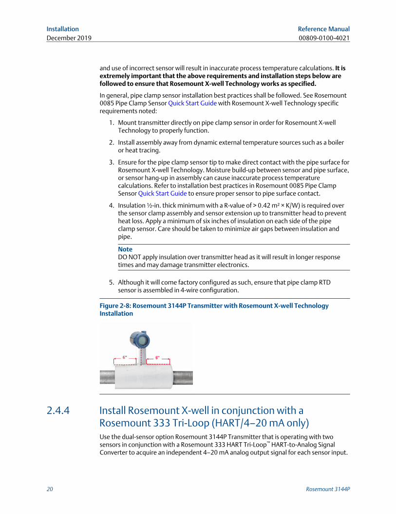
4. Insulation ½-in. thick minimum with a R-value of > 0.42 m² × K/W) is required overthe sensor clamp assembly and sensor extension up to transmitter head to preventheat loss. Apply a minimum of six inches of insulation on each side of the pipeclamp sensor. Care should be taken to minimize air gaps between insulation andpipe.
NoteDO NOT apply insulation over transmitter head as it will result in longer responsetimes and may damage transmitter electronics.
5. Although it will come factory configured as such, ensure that pipe clamp RTDsensor is assembled in 4-wire configuration.
Figure 2-8: Rosemount 3144P Transmitter with Rosemount X-well TechnologyInstallation
2.4.4 Install Rosemount X-well in conjunction with aRosemount 333 Tri-Loop (HART/4–20 mA only)Use the dual-sensor option Rosemount 3144P Transmitter that is operating with twosensors in conjunction with a Rosemount 333 HART Tri-Loop™ HART-to-Analog SignalConverter to acquire an independent 4–20 mA analog output signal for each sensor input.
Installation Reference ManualDecember 2019 00809-0100-4021
20 Rosemount 3144P
The transmitter can be configured to output four of the six following digital processvariables:
• Sensor 1
• Sensor 2
• Differential temperature
• Average temperature
• First good temperature
• Transmitter terminal temperature
• Surface temperature (Rosemount X-well only)
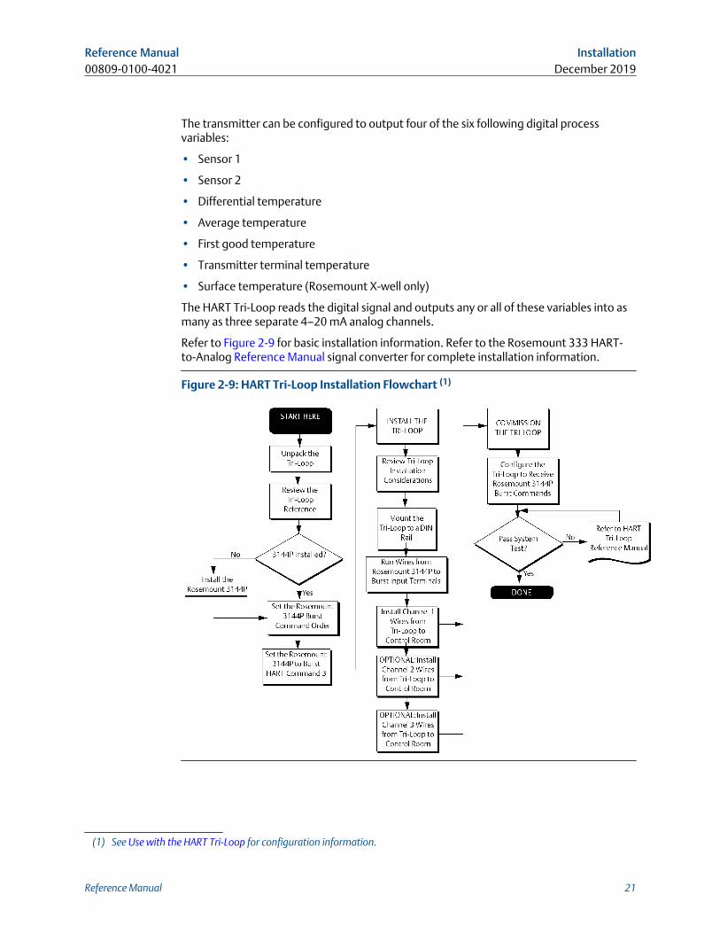
The HART Tri-Loop reads the digital signal and outputs any or all of these variables into asmany as three separate 4–20 mA analog channels.
Refer to Figure 2-9 for basic installation information. Refer to the Rosemount 333 HART-to-Analog Reference Manual signal converter for complete installation information.
Figure 2-9: HART Tri-Loop Installation Flowchart (1)
(1) See Use with the HART Tri-Loop for configuration information.
Reference Manual Installation00809-0100-4021 December 2019
Reference Manual 21
2.4.5 LCD displayTransmitters ordered with the LCD display option (code M5) are shipped with the LCDdisplay installed. After-market installation of the LCD display on a conventional transmitterrequires a small instrument screwdriver and the LCD display kit, which includes:
• LCD display assembly
• Extended cover with cover O-ring in place
• Captive screws (quantity 2)
• 10-pin interconnection header
To install the LCD display:
Procedure
1. If the transmitter is installed in a loop, set the loop to manual (HART)/out-of-service(FOUNDATION Fieldbus) mode and disconnect the power.
2. Remove the housing cover from the electronics side of the transmitter. Do notremove the transmitter covers in explosive atmospheres with a live circuit.
3. Ensure that the transmitter write protect switch is set to the Off position. Iftransmitter security is On, the transmitter cannot be configured to recognize theLCD display. If security On is desired, configure the transmitter for the LCD display,and then install the meter.
4. Insert the interconnection header in the 10-pin socket on the face of the electronicsmodule. Insert the pins into the electronics LCD display interface.
5. The meter can be rotated in 90-degree increments for easy viewing. Position one ofthe four 10-pin sockets on the back of the meter to accept the interconnectionheader.
6. Attach the LCD display assembly to the interconnection pins, then thread andtighten the LCD display screws into the holes on the electronics module.
7. Attach the extended cover; tighten at least one-third turn after the O-ring contactsthe transmitter housing. Both transmitter covers must be fully engaged to meetexplosion proof requirements.
8. Apply power and set the loop to automatic (HART)/in-service (FOUNDATION Fieldbus)mode.
Once the LCD display is installed, configure the transmitter to recognize the meteroption. Refer to LCD display options or LCD display transducer block (index number1200) (FOUNDATION Fieldbus).
NoteObserve the following LCD display temperature limits:
Operating: –40 to 185 °F (–40 to 85 °C)
Storage: –76 to 185 °F (–60 to 85 °C)
Installation Reference ManualDecember 2019 00809-0100-4021
22 Rosemount 3144P
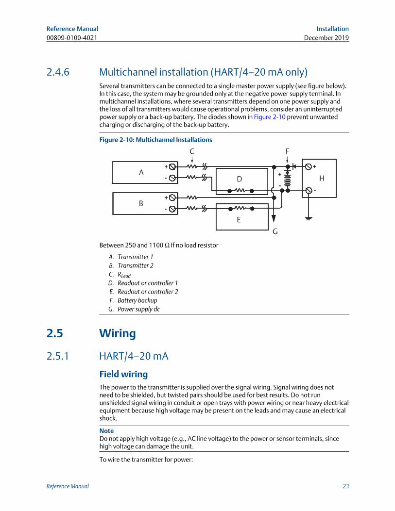
2.4.6 Multichannel installation (HART/4–20 mA only)Several transmitters can be connected to a single master power supply (see figure below).In this case, the system may be grounded only at the negative power supply terminal. Inmultichannel installations, where several transmitters depend on one power supply andthe loss of all transmitters would cause operational problems, consider an uninterruptedpower supply or a back-up battery. The diodes shown in Figure 2-10 prevent unwantedcharging or discharging of the back-up battery.
Figure 2-10: Multichannel Installations
A
B
C
D
E
F
G
H
Between 250 and 1100 Ω If no load resistor
A. Transmitter 1B. Transmitter 2C. RLead
D. Readout or controller 1E. Readout or controller 2F. Battery backupG. Power supply dc
2.5 Wiring
2.5.1 HART/4–20 mA
Field wiringThe power to the transmitter is supplied over the signal wiring. Signal wiring does notneed to be shielded, but twisted pairs should be used for best results. Do not rununshielded signal wiring in conduit or open trays with power wiring or near heavy electricalequipment because high voltage may be present on the leads and may cause an electricalshock.
NoteDo not apply high voltage (e.g., AC line voltage) to the power or sensor terminals, sincehigh voltage can damage the unit.
To wire the transmitter for power:
Reference Manual Installation00809-0100-4021 December 2019
Reference Manual 23
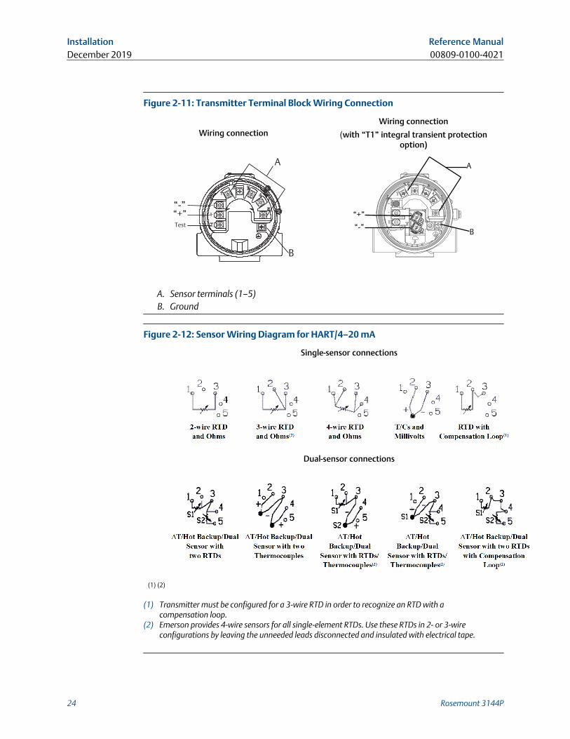
Figure 2-11: Transmitter Terminal Block Wiring Connection
Wiring connectionWiring connection
(with “T1” integral transient protectionoption)
“-”“+”Test
A
B
B
A
“+”
“-”
A. Sensor terminals (1–5)B. Ground
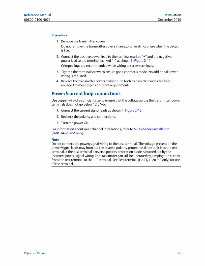
Figure 2-12: Sensor Wiring Diagram for HART/4–20 mA
Single-sensor connections
Dual-sensor connections
(1) (2)
(1) Transmitter must be configured for a 3-wire RTD in order to recognize an RTD with acompensation loop.
(2) Emerson provides 4-wire sensors for all single-element RTDs. Use these RTDs in 2- or 3-wireconfigurations by leaving the unneeded leads disconnected and insulated with electrical tape.
Installation Reference ManualDecember 2019 00809-0100-4021
24 Rosemount 3144P
Procedure
1. Remove the transmitter covers.
Do not remove the transmitter covers in an explosive atmosphere when the circuitis live.
2. Connect the positive power lead to the terminal marked “+” and the negativepower lead to the terminal marked “–” as shown in Figure 2-11.
Crimped lugs are recommended when wiring to screw terminals.
3. Tighten the terminal screws to ensure good contact is made. No additional powerwiring is required.
4. Replace the transmitter covers making sure both transmitter covers are fullyengaged to meet explosion-proof requirements.
Power/current loop connectionsUse copper wire of a sufficient size to ensure that the voltage across the transmitter powerterminals does not go below 12.0 Vdc.
1. Connect the current signal leads as shown in Figure 2-13.
2. Recheck the polarity and connections.
3. Turn the power ON.
For information about multichannel installations, refer to Multichannel installation(HART/4–20 mA only).
NoteDo not connect the power/signal wiring to the test terminal. The voltage present on thepower/signal leads may burn out the reverse-polarity protection diode built into the testterminal. If the test terminal’s reverse polarity protection diode is burned out by theincorrect power/signal wiring, the transmitter can still be operated by jumping the currentfrom the test terminal to the “–” terminal. See Test terminal (HART/4–20 mA only) for useof the terminal.
Reference Manual Installation00809-0100-4021 December 2019
Reference Manual 25
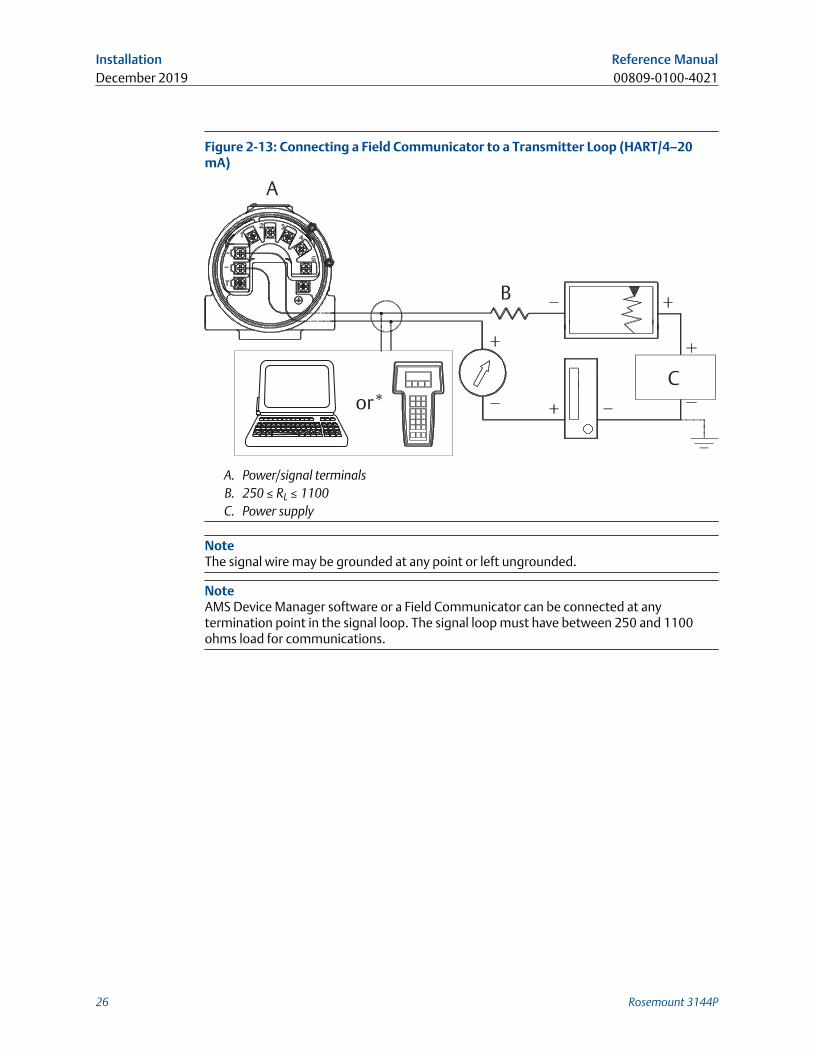
Figure 2-13: Connecting a Field Communicator to a Transmitter Loop (HART/4–20mA)
A
Cor*
B
A. Power/signal terminalsB. 250 ≤ RL ≤ 1100C. Power supply
NoteThe signal wire may be grounded at any point or left ungrounded.
NoteAMS Device Manager software or a Field Communicator can be connected at anytermination point in the signal loop. The signal loop must have between 250 and 1100ohms load for communications.
Installation Reference ManualDecember 2019 00809-0100-4021
26 Rosemount 3144P
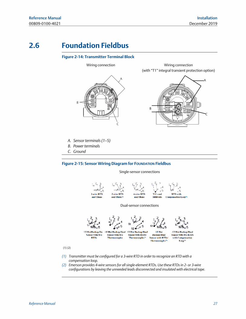
2.6 Foundation FieldbusFigure 2-14: Transmitter Terminal Block
Wiring connection Wiring connection
(with “T1” integral transient protection option)
A
C
B
B
C
A
A. Sensor terminals (1–5)B. Power terminalsC. Ground
Figure 2-15: Sensor Wiring Diagram for FOUNDATION Fieldbus
Single-sensor connections
Dual-sensor connections
(1) (2)
(1) Transmitter must be configured for a 3-wire RTD in order to recognize an RTD with acompensation loop.
(2) Emerson provides 4-wire sensors for all single-element RTDs. Use these RTDs in 2- or 3-wireconfigurations by leaving the unneeded leads disconnected and insulated with electrical tape.
Reference Manual Installation00809-0100-4021 December 2019
Reference Manual 27
RTD or ohm inputs
If the transmitter is mounted remotely from a 3- or 4-wire RTD, it will operate withinspecifications, without recalibration, for lead wire resistances of up to 60 ohms per lead(equivalent to 1,000 ft. of 20 AWG wire). In this case, the leads between the RTD andtransmitter should be shielded. If using only two leads (or a compensation loop lead wireconfiguration), both RTD leads are in series with the sensor element, so significant errorscan occur if the lead lengths exceed one foot of 20 AWG wire. For longer runs, attach athird or fourth lead as described above. To eliminate 2-wire lead resistance error, the 2-wire offset command can be used. This allows the user to input the measured lead wireresistance, resulting in the transmitter adjusting the temperature to correct the error.
When using Rosemount X-well Technology, the Rosemount 3144P TemperatureTransmitter is required to be assembled to a Rosemount 0085 Pipe Clamp RTD Sensor in adirect mount 4-wire configuration. It can be changed to 3- or 2-wired configuration, ifrequired, in the field.
Thermocouple or millivolt inputs
For direct-mount applications, connect the thermocouple directly to the transmitter. Ifmounting the transmitter remotely from the sensor, use appropriate thermocoupleextension wire. Make connections for millivolt inputs with copper wire. Use shielding forlong runs of wire.
NoteFor HART transmitters, the use of two grounded thermocouples with a dual optiontransmitter is not recommended. For applications in which the use of two thermocouplesis desired, connect either two ungrounded thermocouples, one grounded and oneungrounded thermocouple, or one dual element thermocouple.
2.7 Power supplyHART
An external power supply is required to operate the transmitter (not included). The inputvoltage range of the transmitter is 12 to 42.4 Vdc. This is the power required across thetransmitter power terminals. The power terminals are rated to 42.4 Vdc. With 250 ohmsof resistance in the loop, the transmitter requires a minimum of 18.1 Vdc forcommunication.
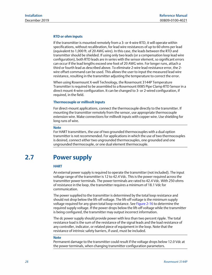
The power supplied to the transmitter is determined by the total loop resistance andshould not drop below the lift-off voltage. The lift-off voltage is the minimum supplyvoltage required for any given total loop resistance. See Figure 2-16 to determine therequired supply voltage. If the power drops below the lift-off voltage while the transmitteris being configured, the transmitter may output incorrect information.
The dc power supply should provide power with less than two percent ripple. The totalresistance load is the sum of the resistance of the signal leads and the load resistance ofany controller, indicator, or related piece of equipment in the loop. Note that theresistance of intrinsic safety barriers, if used, must be included.
NotePermanent damage to the transmitter could result if the voltage drops below 12.0 Vdc atthe power terminals, when changing transmitter configuration parameters.
Installation Reference ManualDecember 2019 00809-0100-4021
28 Rosemount 3144P
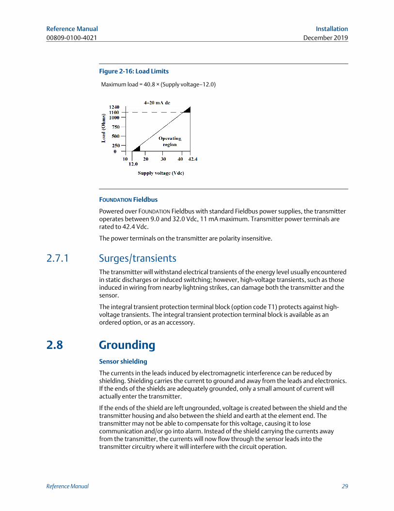
Figure 2-16: Load Limits
Maximum load = 40.8 × (Supply voltage–12.0)
FOUNDATION Fieldbus
Powered over FOUNDATION Fieldbus with standard Fieldbus power supplies, the transmitteroperates between 9.0 and 32.0 Vdc, 11 mA maximum. Transmitter power terminals arerated to 42.4 Vdc.
The power terminals on the transmitter are polarity insensitive.
2.7.1 Surges/transientsThe transmitter will withstand electrical transients of the energy level usually encounteredin static discharges or induced switching; however, high-voltage transients, such as thoseinduced in wiring from nearby lightning strikes, can damage both the transmitter and thesensor.
The integral transient protection terminal block (option code T1) protects against high-voltage transients. The integral transient protection terminal block is available as anordered option, or as an accessory.
2.8 GroundingSensor shielding
The currents in the leads induced by electromagnetic interference can be reduced byshielding. Shielding carries the current to ground and away from the leads and electronics.If the ends of the shields are adequately grounded, only a small amount of current willactually enter the transmitter.
If the ends of the shield are left ungrounded, voltage is created between the shield and thetransmitter housing and also between the shield and earth at the element end. Thetransmitter may not be able to compensate for this voltage, causing it to losecommunication and/or go into alarm. Instead of the shield carrying the currents awayfrom the transmitter, the currents will now flow through the sensor leads into thetransmitter circuitry where it will interfere with the circuit operation.
Reference Manual Installation00809-0100-4021 December 2019
Reference Manual 29
2.8.1 Ungrounded thermocouple, mV, and RTD/ohm inputsOption 1: Recommended for ungrounded transmitter housing
1. Connect the signal wiring shield to the sensor wiring shield.
2. Ensure the two shields are tied together and electrically isolated from thetransmitter housing.
3. Ground the shield at the power supply end only.
4. Ensure the shield at the sensor is electrically isolated from the surrounding fixturesthat may be grounded.
a. Connect shields together, electrically isolated from the transmitter.
A. Sensor wiresB. TransmitterC. 4-20 mA loopD. Shield ground pointE. DCS
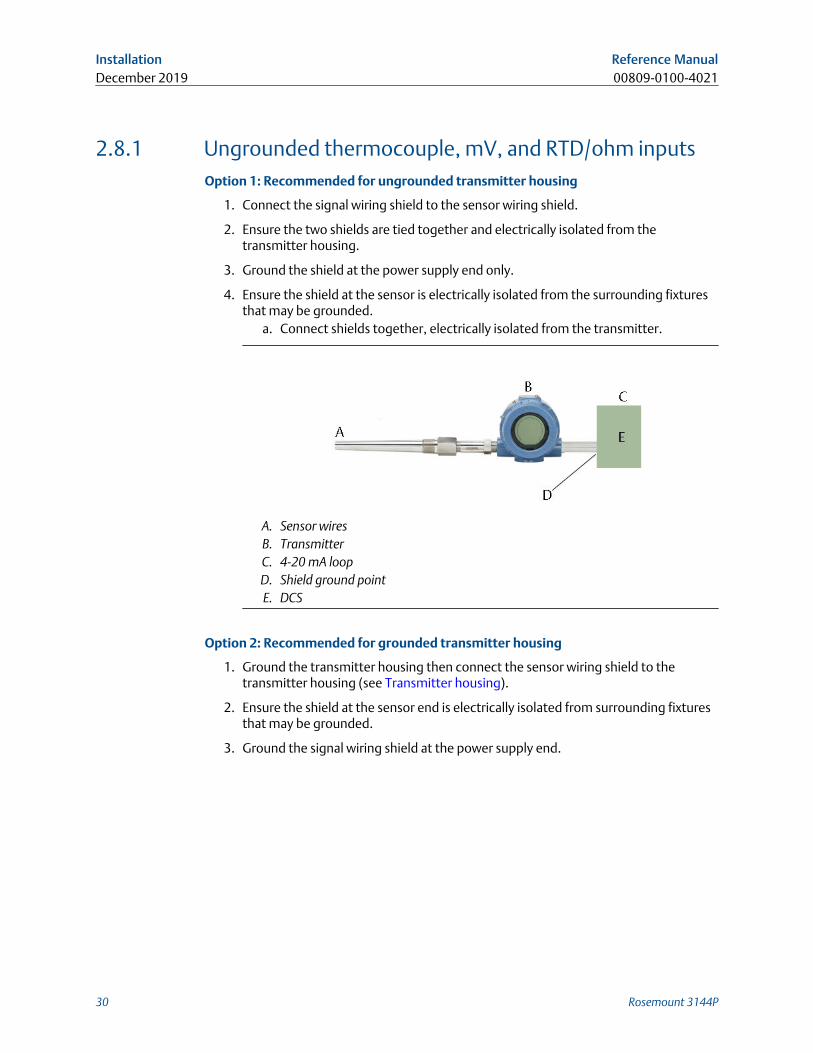
Option 2: Recommended for grounded transmitter housing
1. Ground the transmitter housing then connect the sensor wiring shield to thetransmitter housing (see Transmitter housing).
2. Ensure the shield at the sensor end is electrically isolated from surrounding fixturesthat may be grounded.
3. Ground the signal wiring shield at the power supply end.
Installation Reference ManualDecember 2019 00809-0100-4021
30 Rosemount 3144P
A. Sensor wiresB. TransmitterC. 4-20 mA loopD. Shield ground pointE. DCS
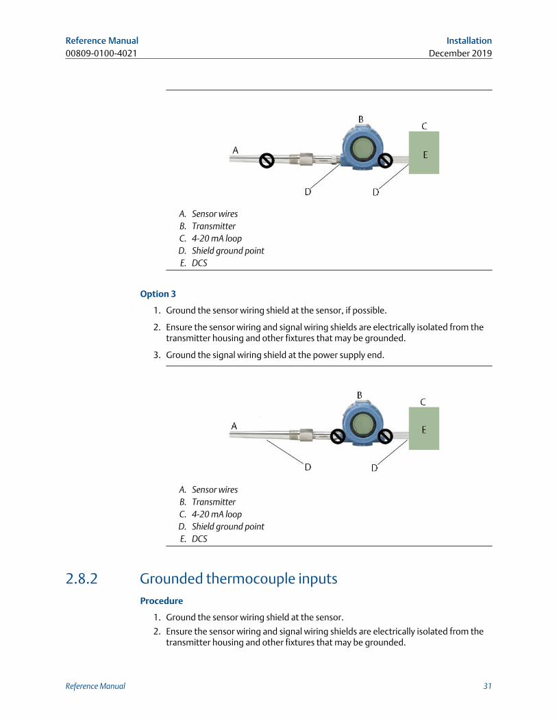
Option 3
1. Ground the sensor wiring shield at the sensor, if possible.
2. Ensure the sensor wiring and signal wiring shields are electrically isolated from thetransmitter housing and other fixtures that may be grounded.
3. Ground the signal wiring shield at the power supply end.
A. Sensor wiresB. TransmitterC. 4-20 mA loopD. Shield ground pointE. DCS
2.8.2 Grounded thermocouple inputsProcedure
1. Ground the sensor wiring shield at the sensor.
2. Ensure the sensor wiring and signal wiring shields are electrically isolated from thetransmitter housing and other fixtures that may be grounded.
Reference Manual Installation00809-0100-4021 December 2019
Reference Manual 31
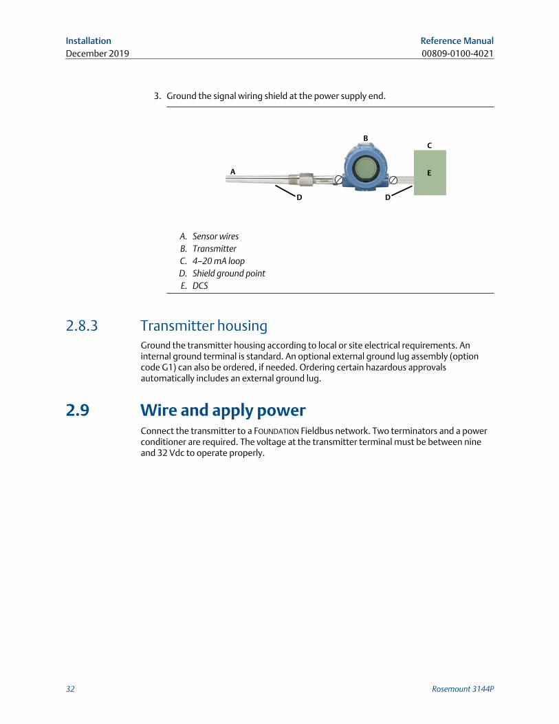
3. Ground the signal wiring shield at the power supply end.
A
B
D
C
E
D
A. Sensor wiresB. TransmitterC. 4–20 mA loopD. Shield ground pointE. DCS
2.8.3 Transmitter housingGround the transmitter housing according to local or site electrical requirements. Aninternal ground terminal is standard. An optional external ground lug assembly (optioncode G1) can also be ordered, if needed. Ordering certain hazardous approvalsautomatically includes an external ground lug.
2.9 Wire and apply powerConnect the transmitter to a FOUNDATION Fieldbus network. Two terminators and a powerconditioner are required. The voltage at the transmitter terminal must be between nineand 32 Vdc to operate properly.
Installation Reference ManualDecember 2019 00809-0100-4021
32 Rosemount 3144P
3 HART Commissioning
3.1 OverviewThis section contains information on commissioning and tasks that should be performedon the bench prior to installation. This section contains Rosemount™ 3144P HART®
Configuration information only. The Field Communicator and instructions are given toperform configuration functions.
For convenience, Field Communicator Fast Key sequences are labeled “Fast Keys” for eachsoftware function below the appropriate headings.
HART 7 Fast Keys 1, 2, 3, etc.
AMS Device Manager help can be found in the AMS Device Manager on-line guides withinthe AMS Device Manager system.
3.2 Confirm HART revision capabilityIf using HART based control or asset management systems, confirm the HART Protocolcapability of those systems prior to transmitter installation. Not all systems are capable ofcommunicating with HART Revision 7. This transmitter can be configured for either HARTRevision 5 or Revision 7.
3.2.1 Switch HART revision modeIf the HART Protocol configuration tool is not capable of communicating with HARTRevision 7, the transmitter will load a generic menu with limited capability. The followingprocedures will switch the HART Revision mode from the generic menu:
Procedure
Select Manual Setup > Device Information > Identification > Message.
a. To change to HART Revision 5, Enter “HART5” in the Message field.
b. To change to HART Revision 5, Enter “HART7” in the Message field.
Reference Manual HART Commissioning00809-0100-4021 December 2019
Reference Manual 33
3.3 Safety messagesInstructions and procedures in this section may require special precautions to ensure thesafety of the personnel performing the operations. Information that potentially raisessafety issues is indicated by a warning symbol ( ). Refer to the following safety messagesbefore performing an operation preceded by this symbol.
WARNING
Explosions could result in death or serious injury.
• Do not remove the instrument cover in explosive atmospheres when the circuit is live.
• Before connecting a handheld communicator in an explosive atmosphere, ensure thatthe instruments in the loop are installed in accordance with intrinsically safe or non-incendive field wiring practices.
• Both transmitter covers must be fully engaged to meet explosion-proof requirements.
Electrical shock could cause death or serious injury.
• If the sensor is installed in a high-voltage environment and a fault or installation erroroccurs, high voltage may be present on transmitter leads and terminals.
• Use extreme caution when making contact with the leads and terminals.
Process leaks could result in death or serious injury.
• Do not remove the thermowell while in operation.
• Install and tighten thermowells and sensors before applying pressure.
3.4 Field CommunicatorThe menu tree and Fast Key sequences use the following device revisions:
• Device dashboard: Device revision 5 and 7, DD v1
The Field Communicator exchanges information with the transmitter from the controlroom, the instrument site, or any wiring termination point in the loop. To facilitatecommunication, connect the Field Communicator in parallel with the transmitter (seeFigure 2-16) using the loop connection ports on the top of the field communicator. Theconnections are non-polarized. Do not make connections to the nickel–cadmium (NiCad)recharger jack in explosive atmospheres. Before connecting the Field Communicator in anexplosive atmosphere, make sure the instruments in the loop are installed according tointrinsically safe or non-incendive field wiring practices.
HART Commissioning Reference ManualDecember 2019 00809-0100-4021
34 Rosemount 3144P
3.4.1 Updating the HART communication softwareThe Field Communicator software may need to be updated to take advantage of theadditional features available in the latest Rosemount 3144P Transmitter. Perform thefollowing steps to determine if an upgrade is necessary.
Procedure
1. Select Rosemount from the list of manufacturers 5 and 6 and 3144 Temp from thelist of models
2. If the Field Device Rev choices include “Dev v1”, “Dev v2”, “Dev v3”, or “Dev v4”(with any DD version), then the user will be able to connect to the device withreduced functionality. To unlock full functionality, download and install the newDD.
NoteThe original release of the safety-certified Rosemount 3144P uses the name “3144PSIS” from the model list and requires “Dev v2, DD v1.”
NoteIf communication is initiated with an improved Rosemount 3144P using acommunicator that only has a previous version of the transmitter device descriptors(DDs), the communicator will display the following message:
NOTICE: Upgrade to the field communicator software to access new XMTR functions.Continue with old description?
YES: The communicator will communicate properly with the transmitter using theexisting transmitter
DDs. However, new software features of the DD in the communicator will not beaccessible.
NO: The communicator will default to a generic transmitter functionality.
If YES is selected after the transmitter is configured to utilize the new features of theimproved transmitters (such as Dual Input configuration or one of the added sensorinput types–DIN Type L or DIN Type U), the user will experience troublecommunicating with the transmitter and will be prompted to turn thecommunicator off. To prevent this from happening, either upgrade thecommunicator to the latest DD or answer NO to the above question and default tothe generic transmitter functionality.
Reference Manual HART Commissioning00809-0100-4021 December 2019
Reference Manual 35
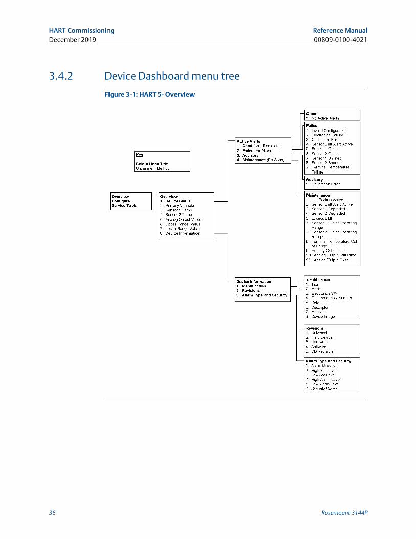
3.4.2 Device Dashboard menu tree
Figure 3-1: HART 5- Overview
HART Commissioning Reference ManualDecember 2019 00809-0100-4021
36 Rosemount 3144P

Figure 3-2: HART 5 - Configure
Reference Manual HART Commissioning00809-0100-4021 December 2019
Reference Manual 37
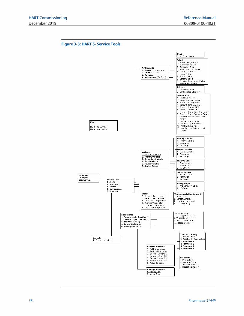
Figure 3-3: HART 5- Service Tools
HART Commissioning Reference ManualDecember 2019 00809-0100-4021
38 Rosemount 3144P
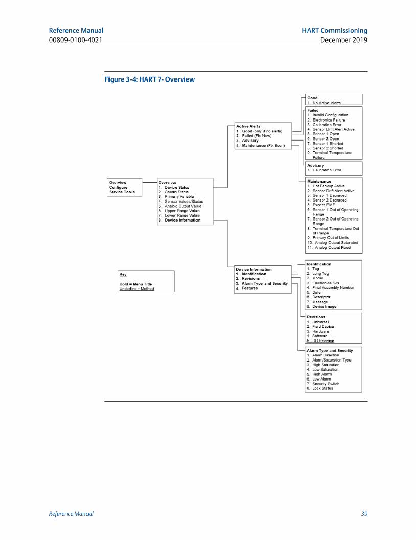
Figure 3-4: HART 7- Overview
Reference Manual HART Commissioning00809-0100-4021 December 2019
Reference Manual 39
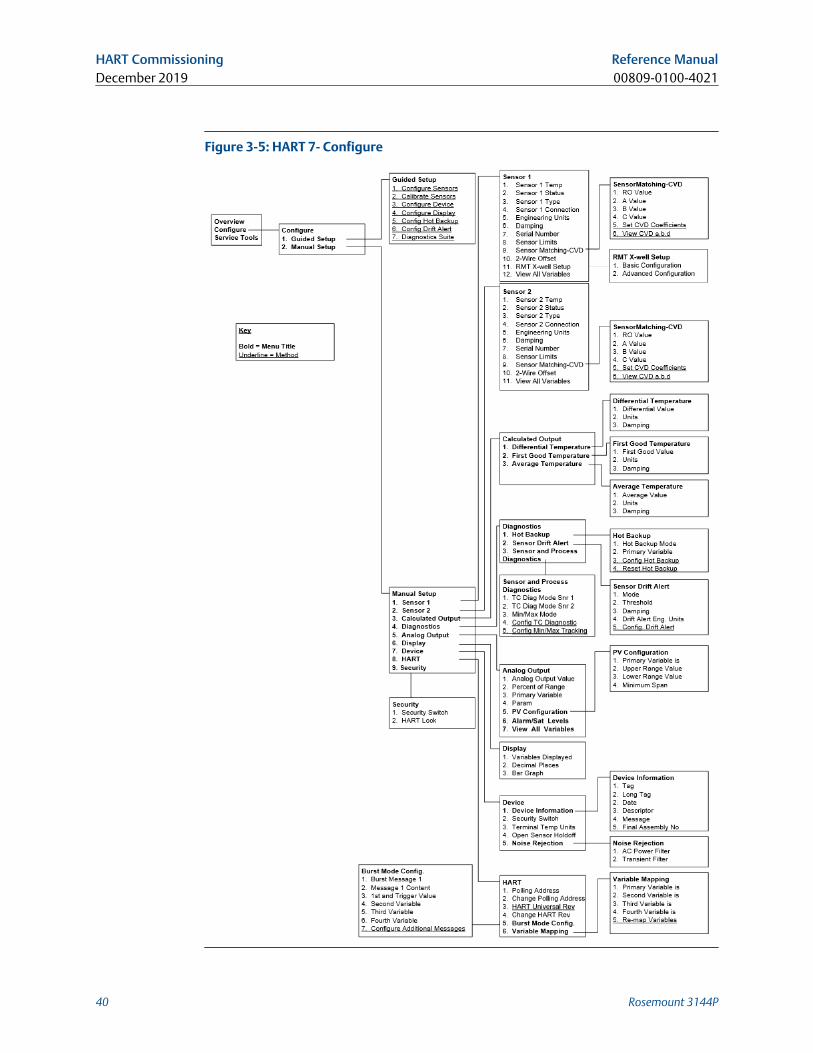
Figure 3-5: HART 7- Configure
HART Commissioning Reference ManualDecember 2019 00809-0100-4021
40 Rosemount 3144P
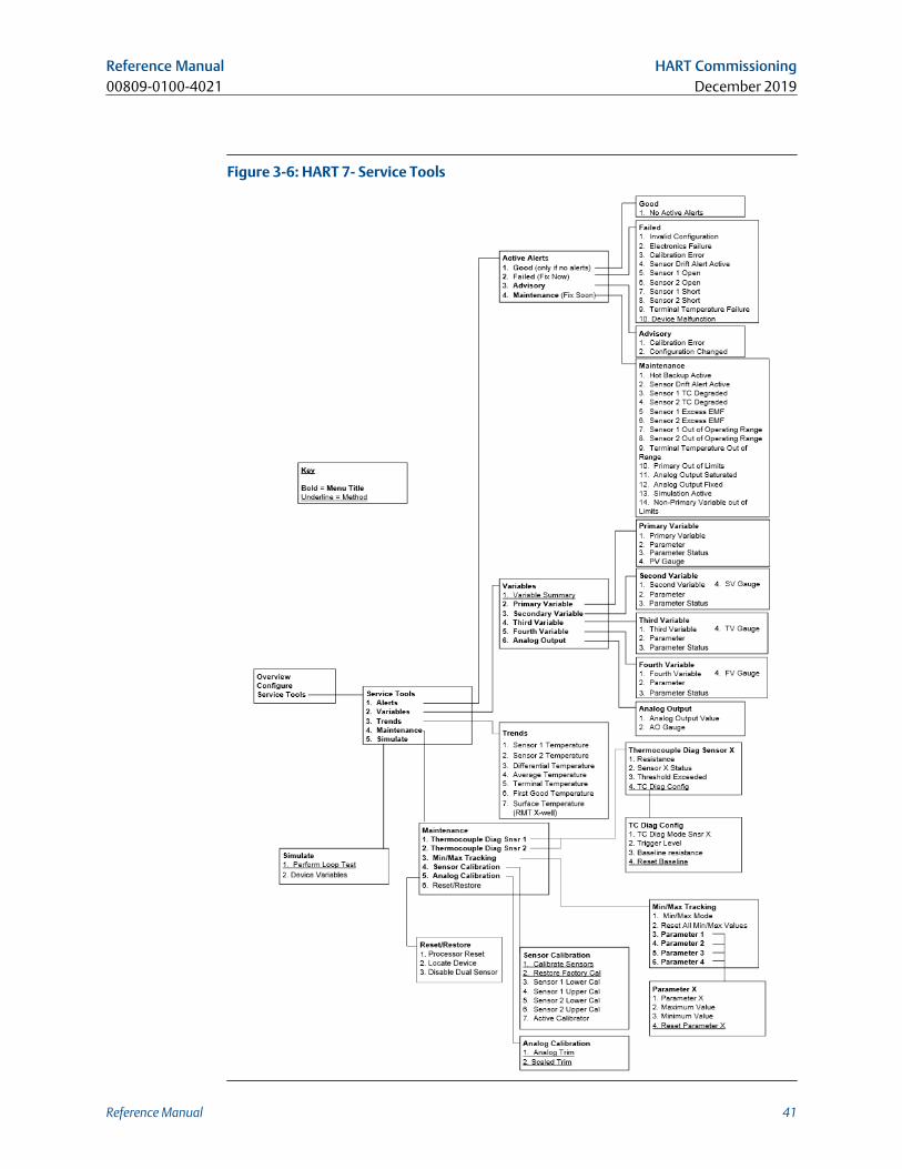
Figure 3-6: HART 7- Service Tools
Reference Manual HART Commissioning00809-0100-4021 December 2019
Reference Manual 41
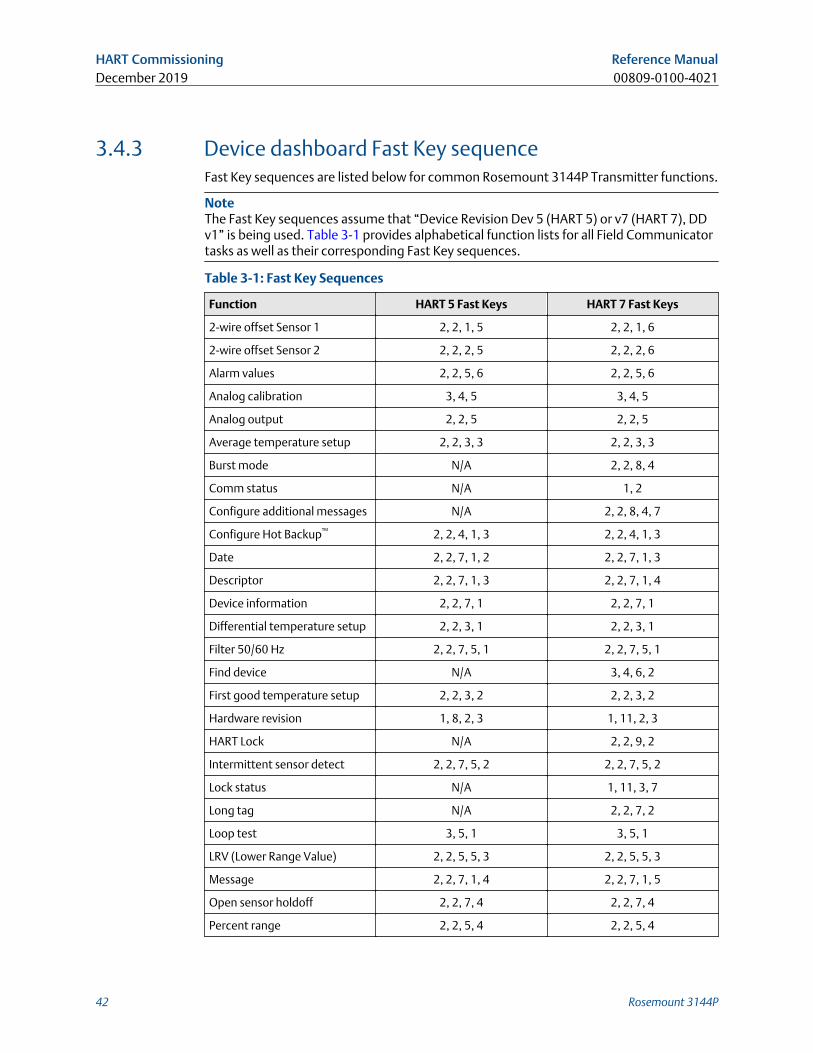
3.4.3 Device dashboard Fast Key sequenceFast Key sequences are listed below for common Rosemount 3144P Transmitter functions.
NoteThe Fast Key sequences assume that “Device Revision Dev 5 (HART 5) or v7 (HART 7), DDv1” is being used. Table 3-1 provides alphabetical function lists for all Field Communicatortasks as well as their corresponding Fast Key sequences.
Table 3-1: Fast Key Sequences
Function HART 5 Fast Keys HART 7 Fast Keys
2-wire offset Sensor 1 2, 2, 1, 5 2, 2, 1, 6
2-wire offset Sensor 2 2, 2, 2, 5 2, 2, 2, 6
Alarm values 2, 2, 5, 6 2, 2, 5, 6
Analog calibration 3, 4, 5 3, 4, 5
Analog output 2, 2, 5 2, 2, 5
Average temperature setup 2, 2, 3, 3 2, 2, 3, 3
Burst mode N/A 2, 2, 8, 4
Comm status N/A 1, 2
Configure additional messages N/A 2, 2, 8, 4, 7
Configure Hot Backup™ 2, 2, 4, 1, 3 2, 2, 4, 1, 3
Date 2, 2, 7, 1, 2 2, 2, 7, 1, 3
Descriptor 2, 2, 7, 1, 3 2, 2, 7, 1, 4
Device information 2, 2, 7, 1 2, 2, 7, 1
Differential temperature setup 2, 2, 3, 1 2, 2, 3, 1
Filter 50/60 Hz 2, 2, 7, 5, 1 2, 2, 7, 5, 1
Find device N/A 3, 4, 6, 2
First good temperature setup 2, 2, 3, 2 2, 2, 3, 2
Hardware revision 1, 8, 2, 3 1, 11, 2, 3
HART Lock N/A 2, 2, 9, 2
Intermittent sensor detect 2, 2, 7, 5, 2 2, 2, 7, 5, 2
Lock status N/A 1, 11, 3, 7
Long tag N/A 2, 2, 7, 2
Loop test 3, 5, 1 3, 5, 1
LRV (Lower Range Value) 2, 2, 5, 5, 3 2, 2, 5, 5, 3
Message 2, 2, 7, 1, 4 2, 2, 7, 1, 5
Open sensor holdoff 2, 2, 7, 4 2, 2, 7, 4
Percent range 2, 2, 5, 4 2, 2, 5, 4
HART Commissioning Reference ManualDecember 2019 00809-0100-4021
42 Rosemount 3144P
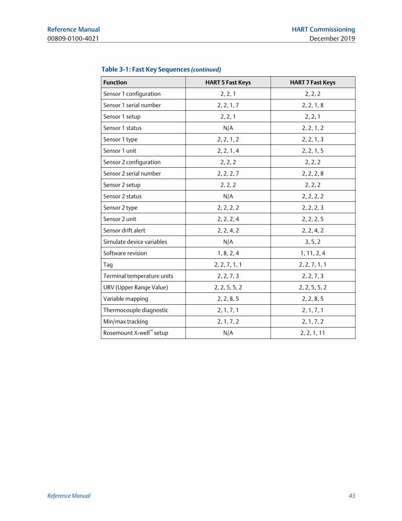
Table 3-1: Fast Key Sequences (continued)
Function HART 5 Fast Keys HART 7 Fast Keys
Sensor 1 configuration 2, 2, 1 2, 2, 2
Sensor 1 serial number 2, 2, 1, 7 2, 2, 1, 8
Sensor 1 setup 2, 2, 1 2, 2, 1
Sensor 1 status N/A 2, 2, 1, 2
Sensor 1 type 2, 2, 1, 2 2, 2, 1, 3
Sensor 1 unit 2, 2, 1, 4 2, 2, 1, 5
Sensor 2 configuration 2, 2, 2 2, 2, 2
Sensor 2 serial number 2, 2, 2, 7 2, 2, 2, 8
Sensor 2 setup 2, 2, 2 2, 2, 2
Sensor 2 status N/A 2, 2, 2, 2
Sensor 2 type 2, 2, 2, 2 2, 2, 2, 3
Sensor 2 unit 2, 2, 2, 4 2, 2, 2, 5
Sensor drift alert 2, 2, 4, 2 2, 2, 4, 2
Simulate device variables N/A 3, 5, 2
Software revision 1, 8, 2, 4 1, 11, 2, 4
Tag 2, 2, 7, 1, 1 2, 2, 7, 1, 1
Terminal temperature units 2, 2, 7, 3 2, 2, 7, 3
URV (Upper Range Value) 2, 2, 5, 5, 2 2, 2, 5, 5, 2
Variable mapping 2, 2, 8, 5 2, 2, 8, 5
Thermocouple diagnostic 2, 1, 7, 1 2, 1, 7, 1
Min/max tracking 2, 1, 7, 2 2, 1, 7, 2
Rosemount X-well™ setup N/A 2, 2, 1, 11
Reference Manual HART Commissioning00809-0100-4021 December 2019
Reference Manual 43
3.5 Review configuration dataBefore operating the transmitter in an actual installation, review all of the factory-setconfiguration data to ensure that it reflects the current application.
3.5.1 ReviewHART 5 Fast Keys 1, 4
HART 7 Fast keys 2, 2
Field Communicator
Review the transmitter configuration parameters set at the factory to ensure accuracy andcompatibility with the particular application. After activating the Review function, scrollthrough the data list and check each variable. If changes to the transmitter configurationdata are necessary, refer to Configuration.
3.6 Check outputBefore performing other transmitter online operations, review the configuration of theRosemount 3144P Transmitter digital output parameters to ensure that the transmitter isoperating properly.
3.6.1 Analog outputHART 5 Fast Keys 2, 2, 5
HART 7 Fast Keys 2, 2, 5
Field Communicator
The Rosemount 3144P process variables provide the transmitter output. The PROCESSVARIABLE menu displays the process variables, including sensed temperature, percentrange, and analog output. These process variables are continuously updated. The primaryvariable is 4–20 mA analog signal.
3.7 ConfigurationThe Rosemount 3144P must have certain basic variables configured to operate. In manycases, these variables are pre-configured at the factory. Configuration may be required ifthe configuration variables need revision.
3.7.1 Variable mappingHART 5 Fast Keys 2, 2, 8, 5
HART 7 Fast Keys 2, 2, 8, 5
HART Commissioning Reference ManualDecember 2019 00809-0100-4021
44 Rosemount 3144P
Field Communicator
The Variable Mapping menu displays the sequence of the process variables. Select 5Variable Re-Map to change this configuration. The Rosemount 3144P single sensor inputconfiguration screens allow selection of the primary variable (PV) and the secondaryvariable (SV). When the Select PV screen appears Snsr 1 or Terminal Temperature mustbe selected.
The Rosemount 3144P dual-sensor option configuration screens allow selection of theprimary variable (PV), secondary variable (SV), tertiary variable (TV), and quaternaryvariable (QV). Variable choices are Sensor 1, Sensor 2, Differential Temperature, AverageTemperature, First-Good Temperature, Terminal Temperature, and Not Used. The primaryvariable is the 4–20 mA analog signal.
3.7.2 Sensor configurationHART 5 Fast Keys 2, 1, 1
HART 7 Fast Keys 2, 1, 1
Field Communicator
Sensor configuration contains information for updating the sensor type, connections,units, and damping.
3.7.3 Change type and connections
HART 5 Fast KeysSensor 1: 2, 2, 1
Sensor 2: 2, 2, 2
HART 7 Fast KeysSensor 1: 2, 2, 1
Sensor 2: 2, 2, 2
The connections command allows the user to select the sensor type and the number ofsensor wires to be connected from the following list:
• 2-, 3-, or 4-wire Pt 100, Rosemount X-well, Pt 200, Pt 500, Pt 1000 (platinum) RTDs (α =0.00385 Ω/Ω/°C)
• 2-, 3-, or 4-wire Pt 100, Pt 200 (platinum) RTDs (α = 0.003916 Ω/Ω/°C)
• 2-, 3-, or 4-wire Ni 120 (nickel) RTDs
• 2-, 3-, or 4-wire Cu 10 (copper) RTDs
• IEC/NIST/DIN Type B, E, J, K, R, S, T thermocouples
• DIN type L, U thermocouples
• ASTM Type W5Re/W26Re thermocouple
• GOST Type L thermocouples
• –10 to 100 millivolts
• 2-, 3-, or 4-wire 0 to 2000 ohms
Reference Manual HART Commissioning00809-0100-4021 December 2019
Reference Manual 45
Contact an Emerson representative for information on temperature sensors, thermowells,and accessory mounting hardware that is available through Emerson.
3.7.4 Output units
HART 5 Fast KeysSensor 1: 2, 2, 1, 4
Sensor 2: 2, 2, 2, 4
HART 7 Fast KeysSensor 1: 2, 2, 1, 5
Sensor 2: 2, 2, 2, 5
The Sensor 1 unit and Sensor 2 unit commands set the desired primary variable units. Thetransmitter output can be set to one of the following engineering units:
• Degrees Celsius
• Degrees Fahrenheit
• Degrees Rankine
• Kelvin
• Ohms
• Millivolts
3.7.5 Sensor 1 serial numberHART 5 Fast Keys 2, 2, 1, 7
HART 7 Fast Keys 2, 2, 1, 8
The serial number of the attached sensor can be listed in the sensor 1 S/N variable. It isuseful for identifying sensors and tracking sensor calibration information.
3.7.6 Sensor 2 serial numberHART 5 Fast Keys 2, 2, 2, 7
HART 7 Fast Keys 2, 2, 2, 8
The serial number of a second sensor can be listed in the sensor 2 S/N variable.
HART Commissioning Reference ManualDecember 2019 00809-0100-4021
46 Rosemount 3144P
3.7.7 2-wire RTD offset
HART 5 Fast KeysSensor 1: 2, 2, 1, 5
Sensor 2: 2, 2, 2, 5
HART 7 Fast KeysSensor 1: 2, 2, 1, 6
Sensor 2: 2, 2, 2, 6
The 2-wire offset command allows the measured lead wire resistance to be input, whichresults in the transmitter adjusting its temperature measurement to correct the errorcaused by this resistance. Because of a lack of lead wire compensation within the RTD,temperature measurements made with a 2-wire RTD are often inaccurate.
3.7.8 Terminal (body) temperatureHART 5 Fast Keys 2, 2, 7, 3
HART 7 Fast Keys 2, 2, 7, 3
The Terminal Temp command sets the terminal temperature units to indicate thetemperature at the transmitter terminals.
3.7.9 Dual-sensor configurationHART 5 Fast Keys 2, 2, 3
HART 7 Fast Keys 2, 2, 3
Dual-sensor configuration sets the functions that can be used with a dual-sensorconfigured transmitter, including differential temperature, average temperature, firstgood temperature.
Differential pressure
HART 5 Fast Keys 2, 2, 3, 1
HART 7 Fast Keys 2, 2, 3, 1
Field Communicator
The transmitter configured for a dual-sensor can accept any two inputs then display thedifferential temperature between them. Use the following procedure with traditional FastKeys to configure the transmitter to measure differential temperature:
NoteThis procedure reports the differential temperature as the primary variable analog signal.If this is not needed, assign differential temperature to the secondary, tertiary, orquaternary variable.
NoteThe transmitter determines the differential temperature by subtracting the reading ofSensor 2 from Sensor 1 (S1– S2). Ensure this order of subtraction is consistent with the
Reference Manual HART Commissioning00809-0100-4021 December 2019
Reference Manual 47
desired reading for the application. Refer to Figure 2-4, or inside the transmitter terminal-side cover for sensor wiring diagrams.
If using an LCD display for local indication, configure the meter to read the appropriatevariables by using LCD display options.
Average temperature
HART 5 Fast Keys 2, 2, 3, 3
HART 7 Fast Keys 2, 2, 3, 3
Field Communicator
The transmitter configured for dual-sensors can output and display the averagetemperature of any two inputs. Use the following procedure with Traditional Fast Keys toconfigure the transmitter to measure the average temperature:
Configure sensor 1 and sensor 2 appropriately. Select 1 Device Setup, 3 Configuration, 2Sensor Configuration, 1 Change Type and Conn. to set the sensor type and number of wiresfor sensor 1. Repeat for Sensor 2.
NoteThis procedure configures the average temperature as the primary variable analog signal.If this is not needed, assign the average temperature to the secondary, tertiary, orquaternary variable.
If using an LCD display, configure it to read the appropriate variables using LCD displayoptions.
NoteIf Sensor 1 and/or sensor 2 should fail while PV is configured for average temperature andthe Hot Backup feature is not enabled, the transmitter will go into alarm. For this reason, itis recommended when PV is sensor average, that the Hot Backup feature be enabled whendual-element sensors are used, or when two temperature measurements are taken fromthe same point in the process. If a sensor failure occurs when the Hot Backup feature isenabled, while PV is sensor average, three scenarios could result:• If sensor 1 fails, the average will only be reading from sensor 2, the working sensor.
• If sensor 2 fails, the average will only be reading from sensor 1, the working sensor.
• If both sensors fail simultaneously, the transmitter will go into alarm and the statusavailable (via HART) states that both sensor 1 and sensor 2 have failed.
In the first two scenarios, the 4–20 mA signal is not disrupted and the status available tothe control system (via HART Protocol) specifies which sensor has failed.
First good configuration
HART 5 Fast Keys 2, 2, 3, 2
HART 7 Fast Keys 2, 2, 3, 2
HART Commissioning Reference ManualDecember 2019 00809-0100-4021
48 Rosemount 3144P
Field Communicator
The first good device variable is useful for applications where dual-sensors (or a single dualelement sensor) are used in a single process. The first good variable will report the sensor 1value, unless sensor 1 fails. When sensor 1 fails, the sensor 2 value will be reported as thefirst good variable. Once the first good variable has switched to sensor 2, it will not revertback to sensor 1 until a master reset occurs or “Suspend Non-PV alarms” is disabled. Whenthe PV is mapped to first good variable and either sensor 1 or sensor 2 fails, the analogoutput will go to the alarm level, but the digital PV value read through the HART Protocolinterface will still report the proper first good sensor value.
If the user does not want the transmitter to go into analog output alarm when the PV ismapped to first good and Sensor 1 fails, enable “Suspend Non-PV Alarm” mode. Thiscombination prevents the analog output from going to the alarm level unless BOTHsensors fail.
Hot Backup feature configuration
HART 5 Fast Keys 2, 2, 4, 1, 3
HART 7 Fast Keys 2, 2, 4, 1, 3
Field Communicator
The config hot BU command configures the transmitter to automatically use sensor 2 asthe primary sensor if sensor 1 fails. With the Hot Backup feature enabled, the primaryvariable (PV) must either be first good or sensor average. See Average temperature fordetails on using the Hot Backup feature when PV is sensor average. Sensors 1 or 2 can bemapped as the secondary variable (SV), tertiary variable (TV), or quaternary variable (QV).In the event of a primary variable (Sensor 1) failure, the transmitter enters the Hot Backupfeature mode and sensor 2 becomes the PV. The 4–20 mA signal is not disrupted, and astatus is available to the control system through HART Protocol that sensor 1 has failed. AnLCD display, if attached, displays the failed sensor status.
While configured to the Hot Backup feature, if sensor 2 fails but sensor 1 is still operatingproperly, the transmitter continues to report the PV 4–20 mA analog output signal, whilea status is available to the control system through HART Protocol that sensor 2 has failed.In the Hot Backup feature mode, the transmitter will not revert back to sensor 1 to controlthe 4–20 mA analog output, until the Hot Backup feature mode is reset by either re-enabling through HART Protocol or by briefly powering down the transmitter.
For information on using the Hot Backup feature in conjunction with the HART Tri-Loopsee Use with the HART Tri-Loop.
Problemdescription:
The unexpected failure of a critical temperature measurement cancause safety issues, environmental or regulatory concerns, andprocess shutdowns.
Our solution: The Hot Backup feature allows the transmitter to automaticallyswitch the transmitter input from the primary sensor to thesecondary sensor should the primary sensor fail. This prevents aprocess disruption due to the failure of the primary sensor. Amaintenance alert is also generated to notify operators that a sensorhas failed and the Hot Backup feature is active.
Reference Manual HART Commissioning00809-0100-4021 December 2019
Reference Manual 49
How it works: Two sensors are wired to a dual-input transmitter. The two sensorsare measured in alternating fashion, so when sensor 1 failure isdetected, the transmitter can immediately switch the output toreflect the sensor 2 value. The switch is automatic with no disruptionto the analog output. The transmitter sends a digital alert to informthe users that the Hot Backup feature is active and the primary sensorneeds investigation.
Take away: “The Hot Backup feature prevents primary sensor failure fromdisrupting process control.”
Targetapplications:
Redundant measurements, critical measurements, trouble spots.
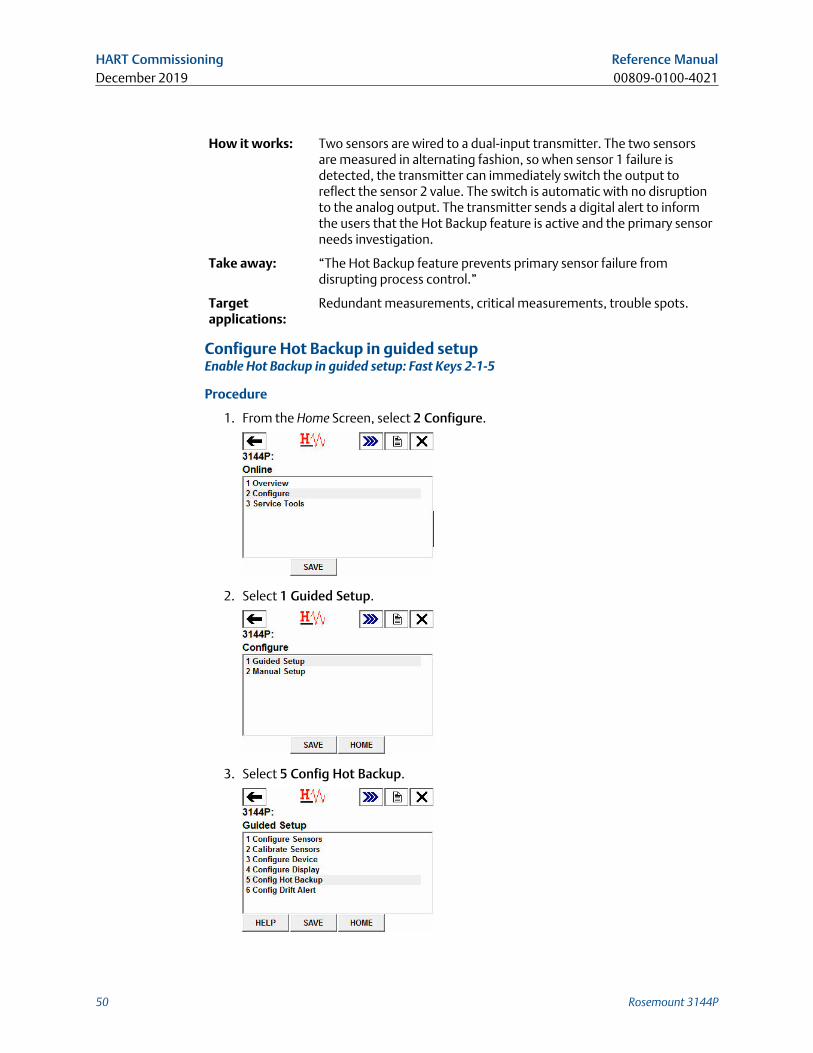
Configure Hot Backup in guided setupEnable Hot Backup in guided setup: Fast Keys 2-1-5
Procedure
1. From the Home Screen, select 2 Configure.
2. Select 1 Guided Setup.
3. Select 5 Config Hot Backup.
HART Commissioning Reference ManualDecember 2019 00809-0100-4021
50 Rosemount 3144P
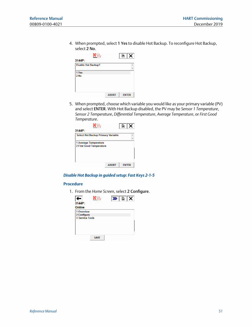
4. When prompted, select 1 Yes to disable Hot Backup. To reconfigure Hot Backup,select 2 No.
5. When prompted, choose which variable you would like as your primary variable (PV)and select ENTER. With Hot Backup disabled, the PV may be Sensor 1 Temperature,Sensor 2 Temperature, Differential Temperature, Average Temperature, or First GoodTemperature.
Disable Hot Backup in guided setup: Fast Keys 2-1-5
Procedure
1. From the Home Screen, select 2 Configure.
Reference Manual HART Commissioning00809-0100-4021 December 2019
Reference Manual 51
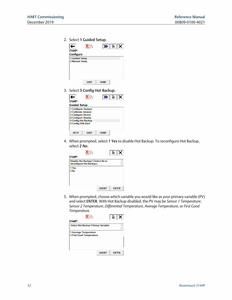
2. Select 1 Guided Setup.
3. Select 5 Config Hot Backup.
4. When prompted, select 1 Yes to disable Hot Backup. To reconfigure Hot Backup,select 2 No.
5. When prompted, choose which variable you would like as your primary variable (PV)and select ENTER. With Hot Backup disabled, the PV may be Sensor 1 Temperature,Sensor 2 Temperature, Differential Temperature, Average Temperature, or First GoodTemperature.
HART Commissioning Reference ManualDecember 2019 00809-0100-4021
52 Rosemount 3144P
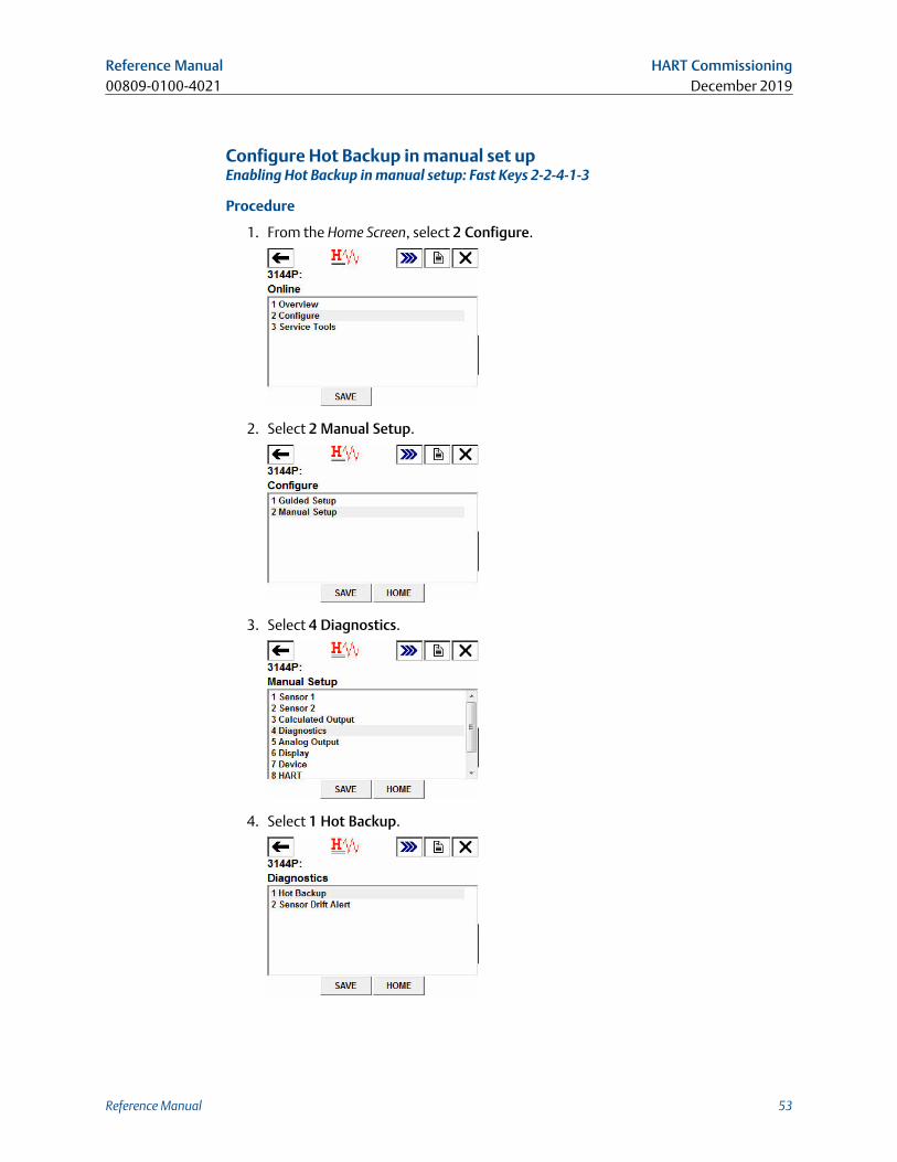
Configure Hot Backup in manual set upEnabling Hot Backup in manual setup: Fast Keys 2-2-4-1-3
Procedure
1. From the Home Screen, select 2 Configure.
2. Select 2 Manual Setup.
3. Select 4 Diagnostics.
4. Select 1 Hot Backup.
Reference Manual HART Commissioning00809-0100-4021 December 2019
Reference Manual 53
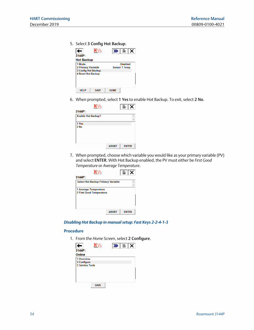
5. Select 3 Config Hot Backup.
6. When prompted, select 1 Yes to enable Hot Backup. To exit, select 2 No.
7. When prompted, choose which variable you would like as your primary variable (PV)and select ENTER. With Hot Backup enabled, the PV must either be First GoodTemperature or Average Temperature.
Disabling Hot Backup in manual setup: Fast Keys 2-2-4-1-3
Procedure
1. From the Home Screen, select 2 Configure.
HART Commissioning Reference ManualDecember 2019 00809-0100-4021
54 Rosemount 3144P
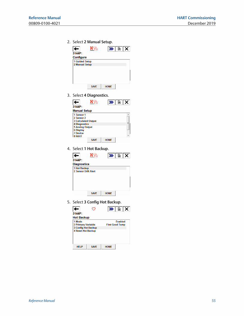
2. Select 2 Manual Setup.
3. Select 4 Diagnostics.
4. Select 1 Hot Backup.
5. Select 3 Config Hot Backup.
Reference Manual HART Commissioning00809-0100-4021 December 2019
Reference Manual 55
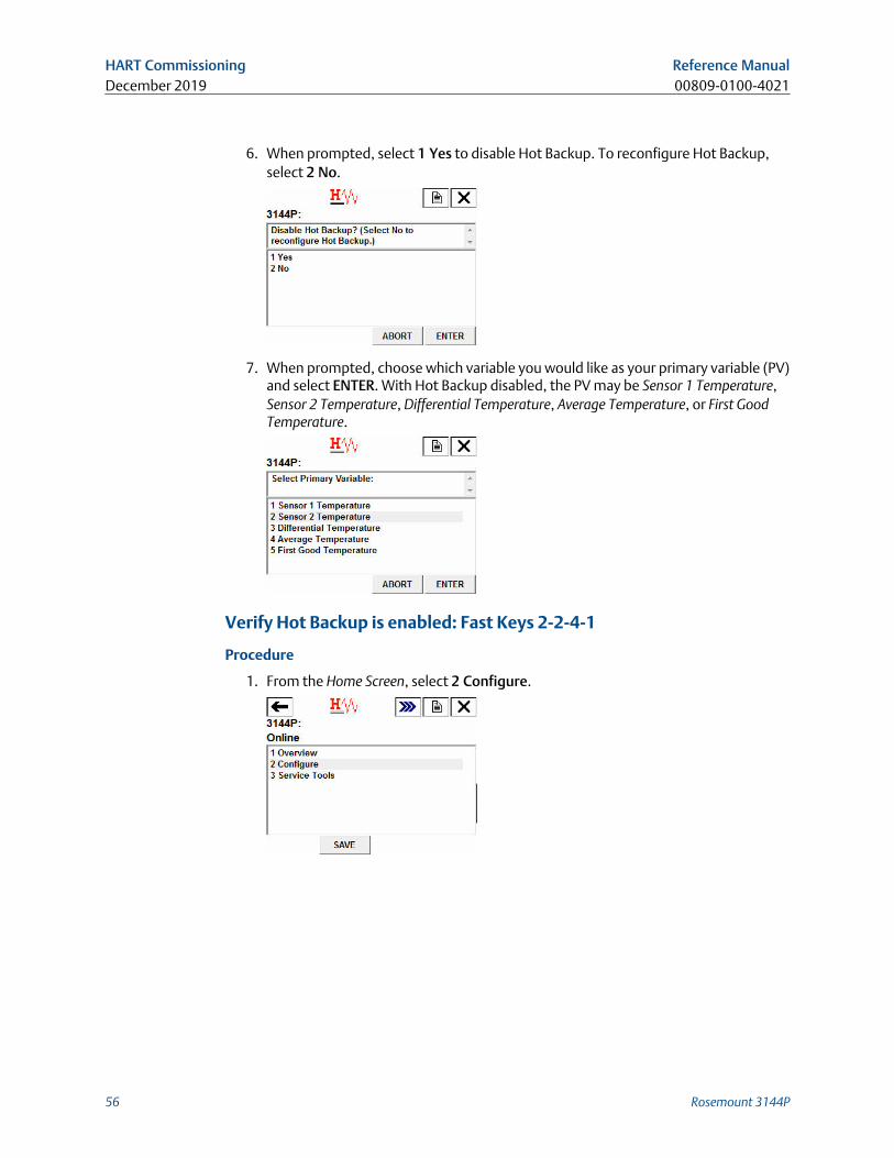
6. When prompted, select 1 Yes to disable Hot Backup. To reconfigure Hot Backup,select 2 No.
7. When prompted, choose which variable you would like as your primary variable (PV)and select ENTER. With Hot Backup disabled, the PV may be Sensor 1 Temperature,Sensor 2 Temperature, Differential Temperature, Average Temperature, or First GoodTemperature.
Verify Hot Backup is enabled: Fast Keys 2-2-4-1
Procedure
1. From the Home Screen, select 2 Configure.
HART Commissioning Reference ManualDecember 2019 00809-0100-4021
56 Rosemount 3144P
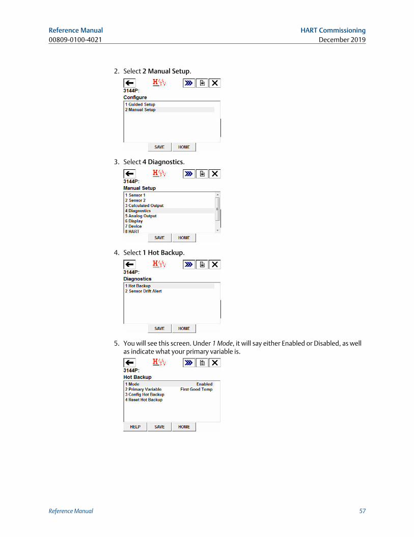
2. Select 2 Manual Setup.
3. Select 4 Diagnostics.
4. Select 1 Hot Backup.
5. You will see this screen. Under 1 Mode, it will say either Enabled or Disabled, as wellas indicate what your primary variable is.
Reference Manual HART Commissioning00809-0100-4021 December 2019
Reference Manual 57
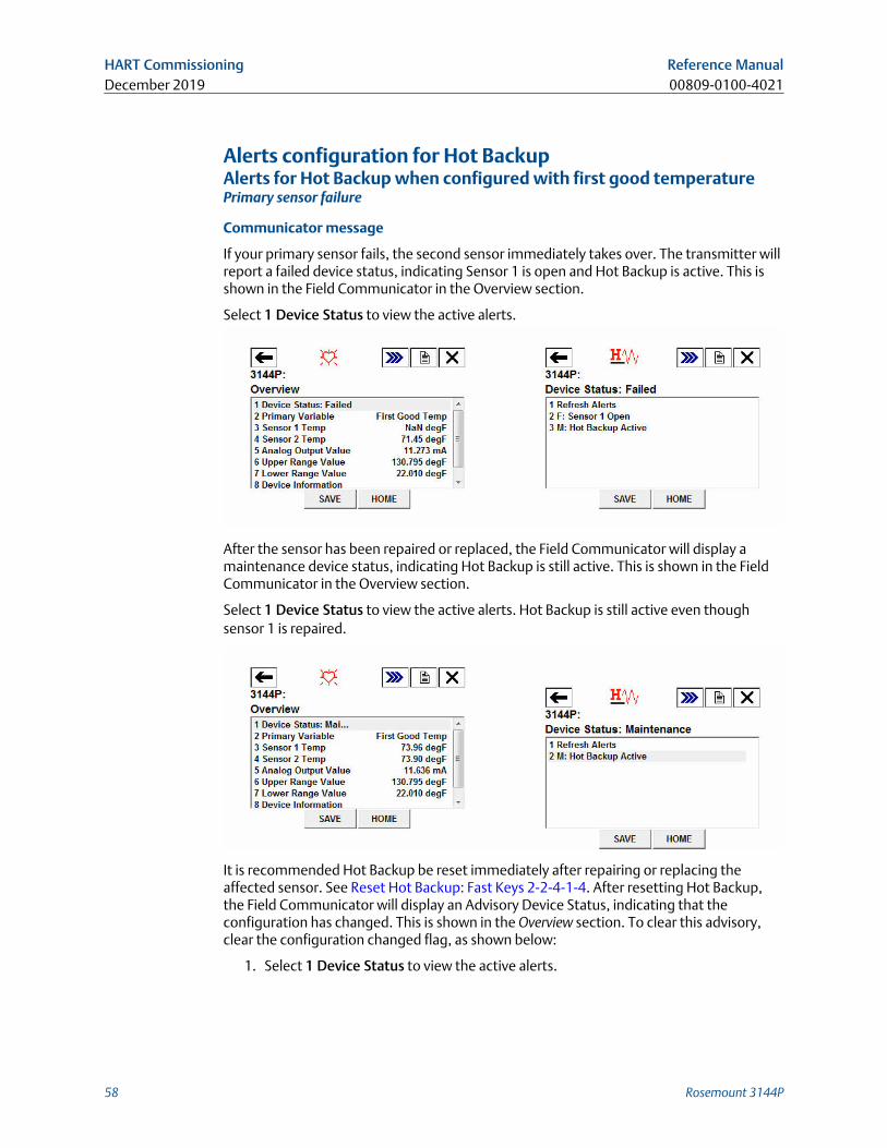
Alerts configuration for Hot BackupAlerts for Hot Backup when configured with first good temperaturePrimary sensor failure
Communicator message
If your primary sensor fails, the second sensor immediately takes over. The transmitter willreport a failed device status, indicating Sensor 1 is open and Hot Backup is active. This isshown in the Field Communicator in the Overview section.
Select 1 Device Status to view the active alerts.
After the sensor has been repaired or replaced, the Field Communicator will display amaintenance device status, indicating Hot Backup is still active. This is shown in the FieldCommunicator in the Overview section.
Select 1 Device Status to view the active alerts. Hot Backup is still active even thoughsensor 1 is repaired.
It is recommended Hot Backup be reset immediately after repairing or replacing theaffected sensor. See Reset Hot Backup: Fast Keys 2-2-4-1-4. After resetting Hot Backup,the Field Communicator will display an Advisory Device Status, indicating that theconfiguration has changed. This is shown in the Overview section. To clear this advisory,clear the configuration changed flag, as shown below:
1. Select 1 Device Status to view the active alerts.
HART Commissioning Reference ManualDecember 2019 00809-0100-4021
58 Rosemount 3144P
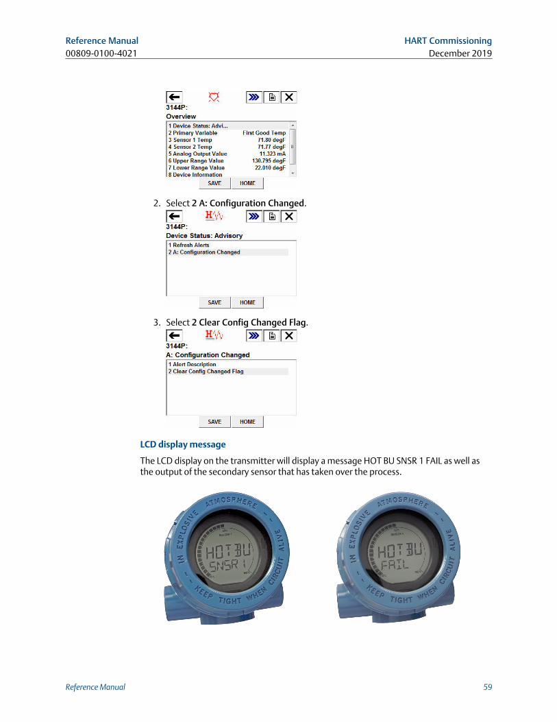
2. Select 2 A: Configuration Changed.
3. Select 2 Clear Config Changed Flag.
LCD display message
The LCD display on the transmitter will display a message HOT BU SNSR 1 FAIL as well asthe output of the secondary sensor that has taken over the process.
Reference Manual HART Commissioning00809-0100-4021 December 2019
Reference Manual 59
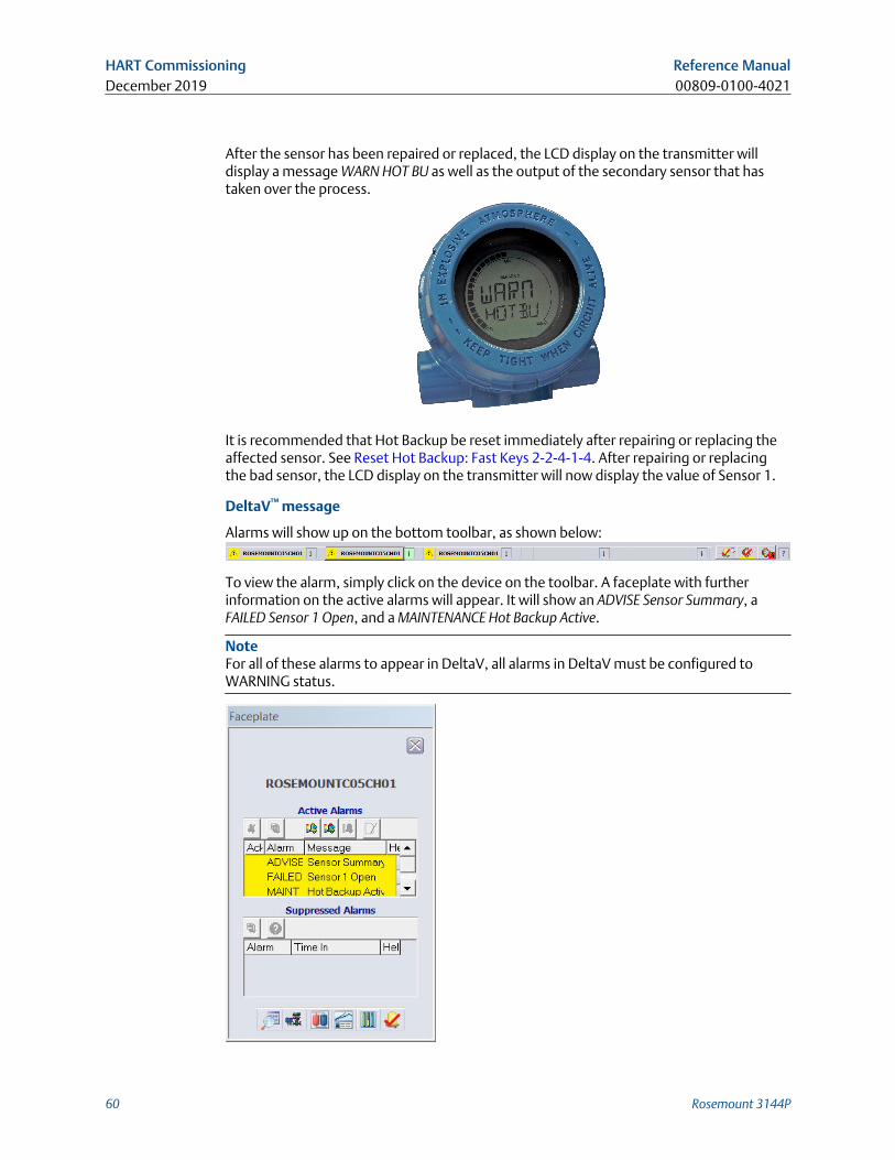
After the sensor has been repaired or replaced, the LCD display on the transmitter willdisplay a message WARN HOT BU as well as the output of the secondary sensor that hastaken over the process.
It is recommended that Hot Backup be reset immediately after repairing or replacing theaffected sensor. See Reset Hot Backup: Fast Keys 2-2-4-1-4. After repairing or replacingthe bad sensor, the LCD display on the transmitter will now display the value of Sensor 1.
DeltaV™ message
Alarms will show up on the bottom toolbar, as shown below:
To view the alarm, simply click on the device on the toolbar. A faceplate with furtherinformation on the active alarms will appear. It will show an ADVISE Sensor Summary, aFAILED Sensor 1 Open, and a MAINTENANCE Hot Backup Active.
NoteFor all of these alarms to appear in DeltaV, all alarms in DeltaV must be configured toWARNING status.
HART Commissioning Reference ManualDecember 2019 00809-0100-4021
60 Rosemount 3144P
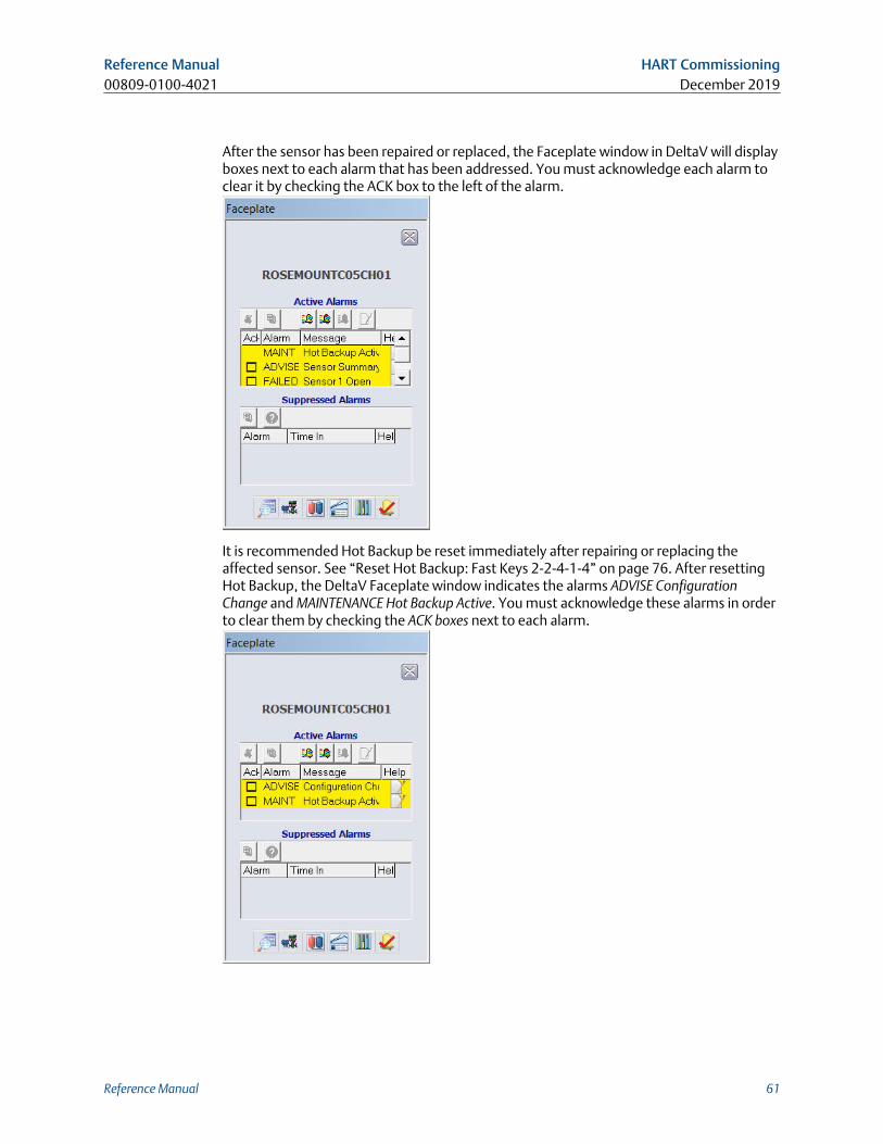
After the sensor has been repaired or replaced, the Faceplate window in DeltaV will displayboxes next to each alarm that has been addressed. You must acknowledge each alarm toclear it by checking the ACK box to the left of the alarm.
It is recommended Hot Backup be reset immediately after repairing or replacing theaffected sensor. See “Reset Hot Backup: Fast Keys 2-2-4-1-4” on page 76. After resettingHot Backup, the DeltaV Faceplate window indicates the alarms ADVISE ConfigurationChange and MAINTENANCE Hot Backup Active. You must acknowledge these alarms in orderto clear them by checking the ACK boxes next to each alarm.
Reference Manual HART Commissioning00809-0100-4021 December 2019
Reference Manual 61
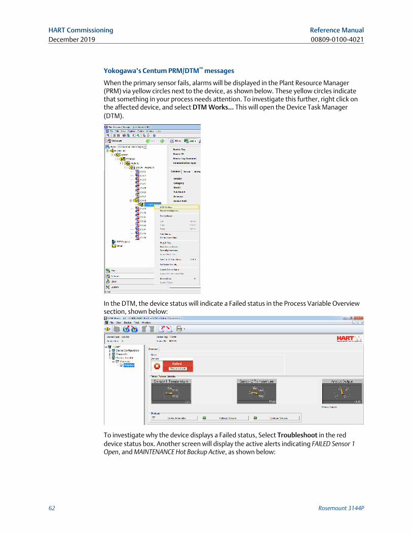
Yokogawa’s Centum PRM/DTM™ messages
When the primary sensor fails, alarms will be displayed in the Plant Resource Manager(PRM) via yellow circles next to the device, as shown below. These yellow circles indicatethat something in your process needs attention. To investigate this further, right click onthe affected device, and select DTM Works… This will open the Device Task Manager(DTM).
In the DTM, the device status will indicate a Failed status in the Process Variable Overviewsection, shown below:
To investigate why the device displays a Failed status, Select Troubleshoot in the reddevice status box. Another screen will display the active alerts indicating FAILED Sensor 1Open, and MAINTENANCE Hot Backup Active, as shown below:
HART Commissioning Reference ManualDecember 2019 00809-0100-4021
62 Rosemount 3144P
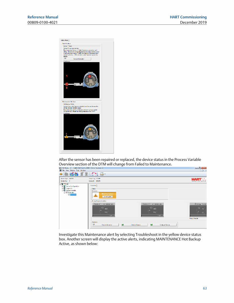
After the sensor has been repaired or replaced, the device status in the Process VariableOverview section of the DTM will change from Failed to Maintenance.
Investigate this Maintenance alert by selecting Troubleshoot in the yellow device statusbox. Another screen will display the active alerts, indicating MAINTENANCE Hot BackupActive, as shown below:
Reference Manual HART Commissioning00809-0100-4021 December 2019
Reference Manual 63
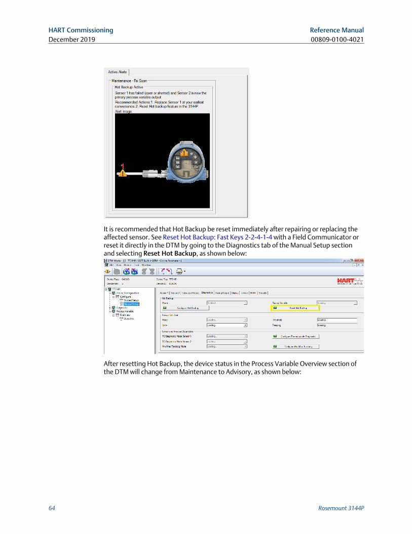
It is recommended that Hot Backup be reset immediately after repairing or replacing theaffected sensor. See Reset Hot Backup: Fast Keys 2-2-4-1-4 with a Field Communicator orreset it directly in the DTM by going to the Diagnostics tab of the Manual Setup sectionand selecting Reset Hot Backup, as shown below:
After resetting Hot Backup, the device status in the Process Variable Overview section ofthe DTM will change from Maintenance to Advisory, as shown below:
HART Commissioning Reference ManualDecember 2019 00809-0100-4021
64 Rosemount 3144P
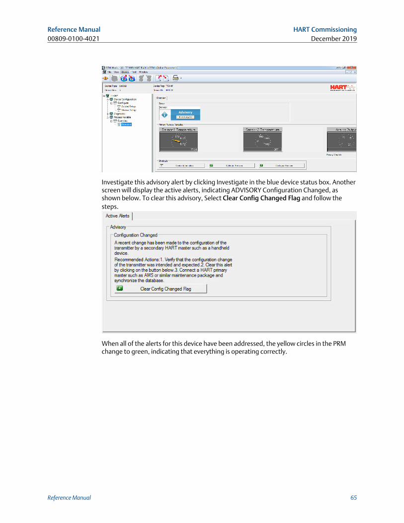
Investigate this advisory alert by clicking Investigate in the blue device status box. Anotherscreen will display the active alerts, indicating ADVISORY Configuration Changed, asshown below. To clear this advisory, Select Clear Config Changed Flag and follow thesteps.
When all of the alerts for this device have been addressed, the yellow circles in the PRMchange to green, indicating that everything is operating correctly.
Reference Manual HART Commissioning00809-0100-4021 December 2019
Reference Manual 65
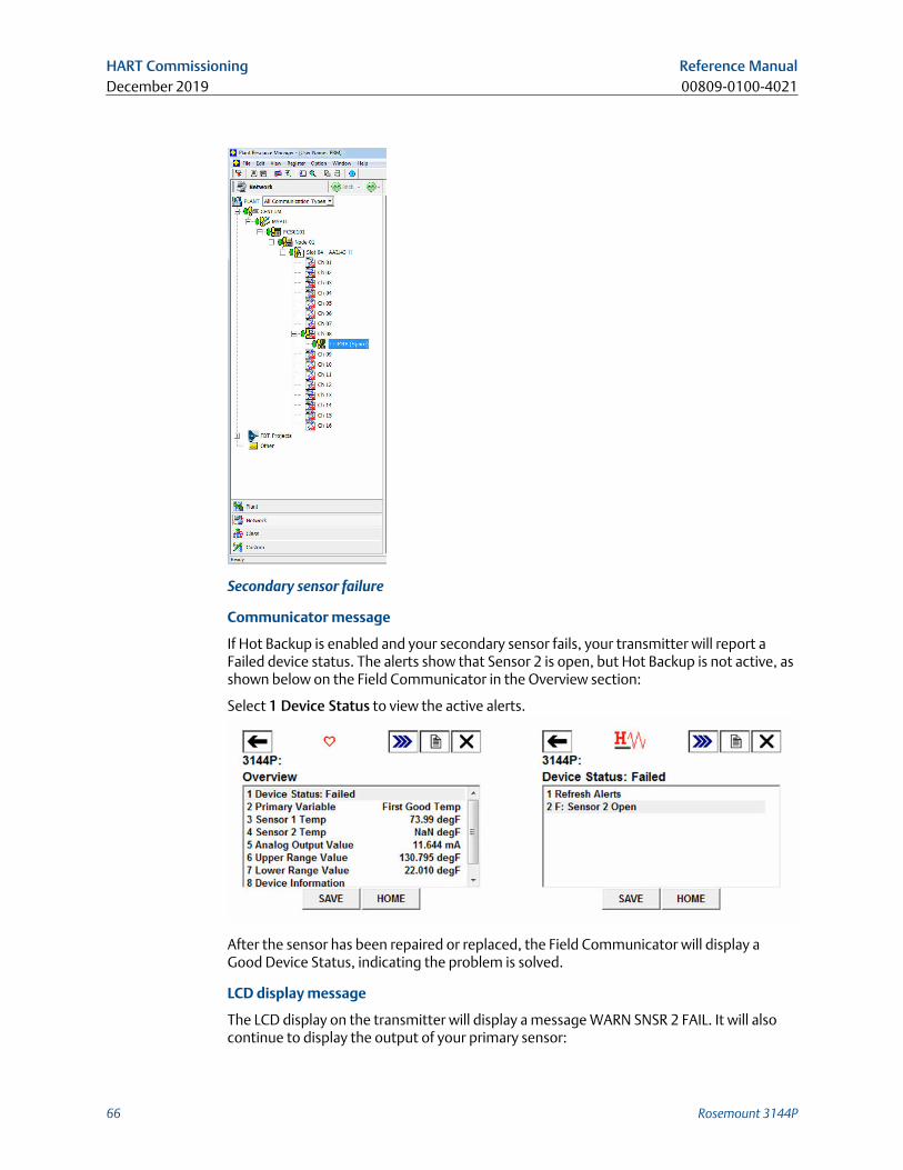
Secondary sensor failure
Communicator message
If Hot Backup is enabled and your secondary sensor fails, your transmitter will report aFailed device status. The alerts show that Sensor 2 is open, but Hot Backup is not active, asshown below on the Field Communicator in the Overview section:
Select 1 Device Status to view the active alerts.
After the sensor has been repaired or replaced, the Field Communicator will display aGood Device Status, indicating the problem is solved.
LCD display message
The LCD display on the transmitter will display a message WARN SNSR 2 FAIL. It will alsocontinue to display the output of your primary sensor:
HART Commissioning Reference ManualDecember 2019 00809-0100-4021
66 Rosemount 3144P
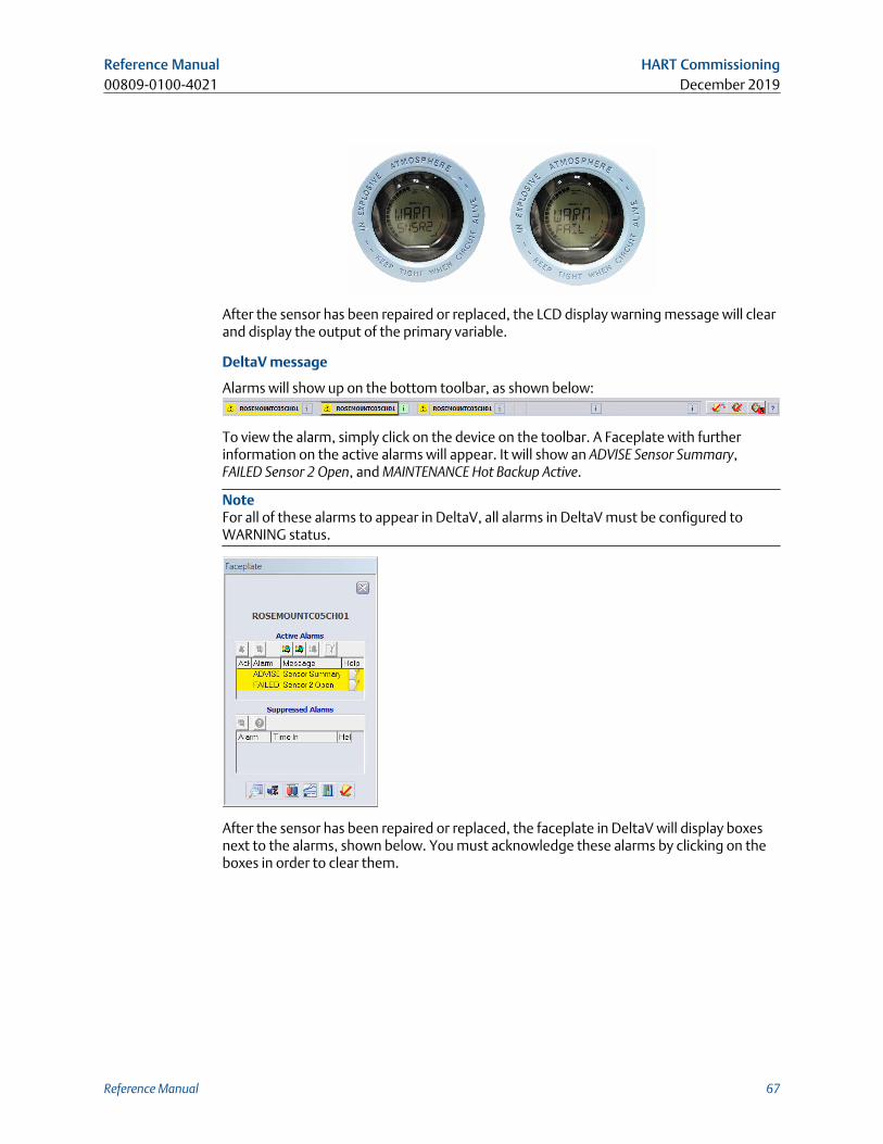
After the sensor has been repaired or replaced, the LCD display warning message will clearand display the output of the primary variable.
DeltaV message
Alarms will show up on the bottom toolbar, as shown below:
To view the alarm, simply click on the device on the toolbar. A Faceplate with furtherinformation on the active alarms will appear. It will show an ADVISE Sensor Summary,FAILED Sensor 2 Open, and MAINTENANCE Hot Backup Active.
NoteFor all of these alarms to appear in DeltaV, all alarms in DeltaV must be configured toWARNING status.
After the sensor has been repaired or replaced, the faceplate in DeltaV will display boxesnext to the alarms, shown below. You must acknowledge these alarms by clicking on theboxes in order to clear them.
Reference Manual HART Commissioning00809-0100-4021 December 2019
Reference Manual 67
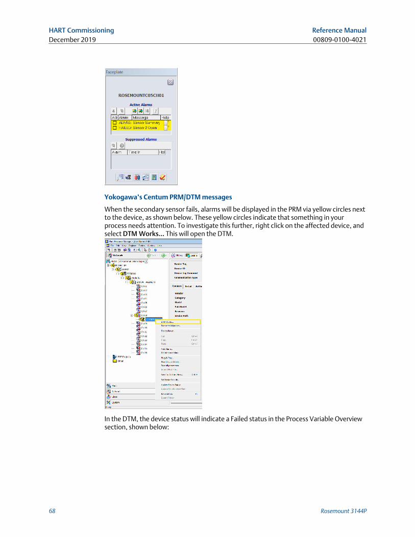
Yokogawa’s Centum PRM/DTM messages
When the secondary sensor fails, alarms will be displayed in the PRM via yellow circles nextto the device, as shown below. These yellow circles indicate that something in yourprocess needs attention. To investigate this further, right click on the affected device, andselect DTM Works… This will open the DTM.
In the DTM, the device status will indicate a Failed status in the Process Variable Overviewsection, shown below:
HART Commissioning Reference ManualDecember 2019 00809-0100-4021
68 Rosemount 3144P
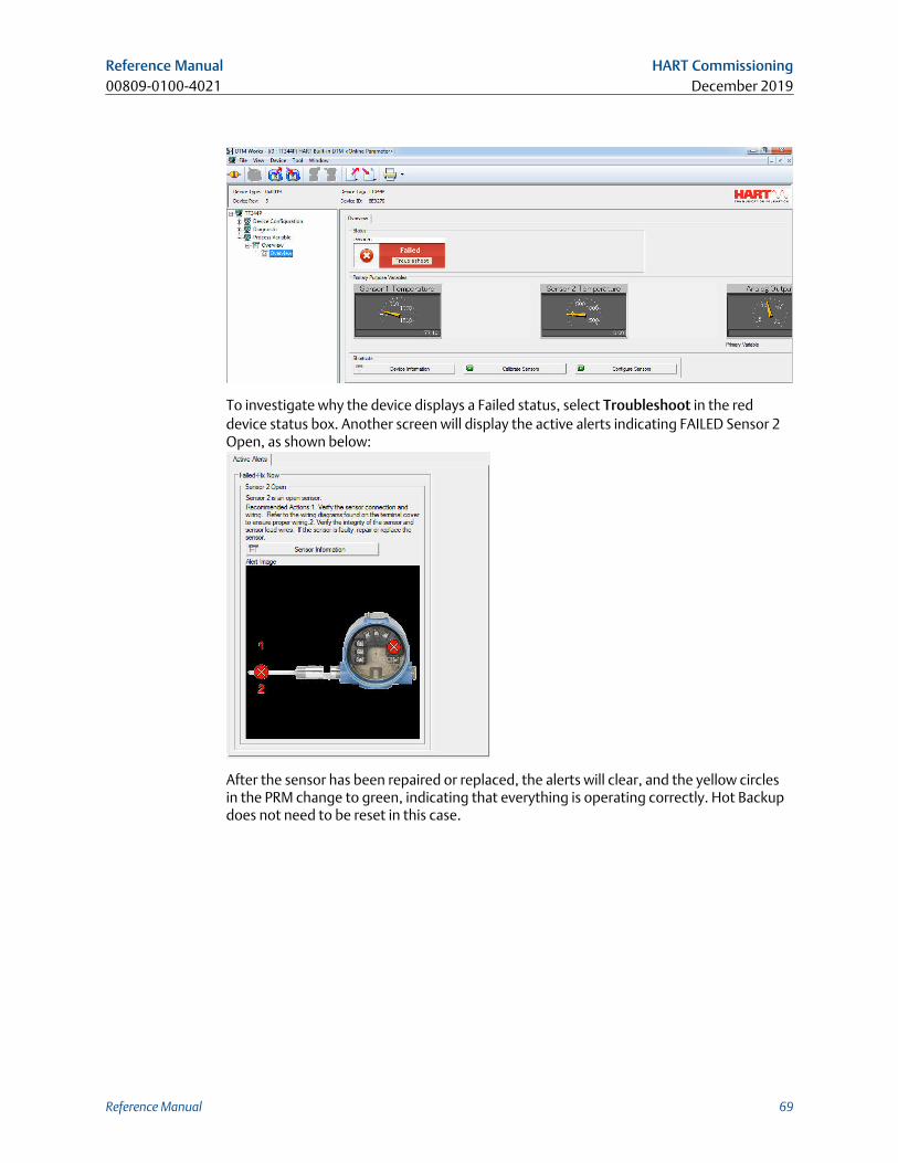
To investigate why the device displays a Failed status, select Troubleshoot in the reddevice status box. Another screen will display the active alerts indicating FAILED Sensor 2Open, as shown below:
After the sensor has been repaired or replaced, the alerts will clear, and the yellow circlesin the PRM change to green, indicating that everything is operating correctly. Hot Backupdoes not need to be reset in this case.
Reference Manual HART Commissioning00809-0100-4021 December 2019
Reference Manual 69
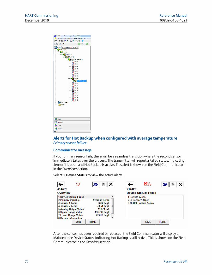
Alerts for Hot Backup when configured with average temperaturePrimary sensor failure
Communicator message
If your primary sensor fails, there will be a seamless transition where the second sensorimmediately takes over the process. The transmitter will report a Failed status, indicatingSensor 1 is open and Hot Backup is active. This alert is shown on the Field Communicatorin the Overview section.
Select 1 Device Status to view the active alerts.
After the sensor has been repaired or replaced, the Field Communicator will display aMaintenance Device Status, indicating Hot Backup is still active. This is shown on the FieldCommunicator in the Overview section.
HART Commissioning Reference ManualDecember 2019 00809-0100-4021
70 Rosemount 3144P
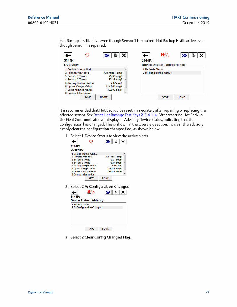
Hot Backup is still active even though Sensor 1 is repaired. Hot Backup is still active eventhough Sensor 1 is repaired.
It is recommended that Hot Backup be reset immediately after repairing or replacing theaffected sensor. See Reset Hot Backup: Fast Keys 2-2-4-1-4. After resetting Hot Backup,the Field Communicator will display an Advisory Device Status, indicating that theconfiguration has changed. This is shown in the Overview section. To clear this advisory,simply clear the configuration changed flag, as shown below:
1. Select 1 Device Status to view the active alerts.
2. Select 2 A: Configuration Changed.
3. Select 2 Clear Config Changed Flag.
Reference Manual HART Commissioning00809-0100-4021 December 2019
Reference Manual 71
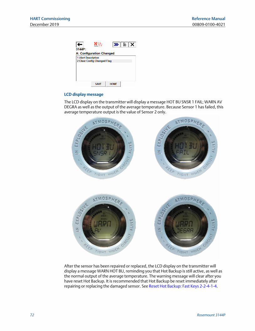
LCD display message
The LCD display on the transmitter will display a message HOT BU SNSR 1 FAIL; WARN AVDEGRA as well as the output of the average temperature. Because Sensor 1 has failed, thisaverage temperature output is the value of Sensor 2 only.
After the sensor has been repaired or replaced, the LCD display on the transmitter willdisplay a message WARN HOT BU, reminding you that Hot Backup is still active, as well asthe normal output of the average temperature. The warning message will clear after youhave reset Hot Backup. It is recommended that Hot Backup be reset immediately afterrepairing or replacing the damaged sensor. See Reset Hot Backup: Fast Keys 2-2-4-1-4.
HART Commissioning Reference ManualDecember 2019 00809-0100-4021
72 Rosemount 3144P
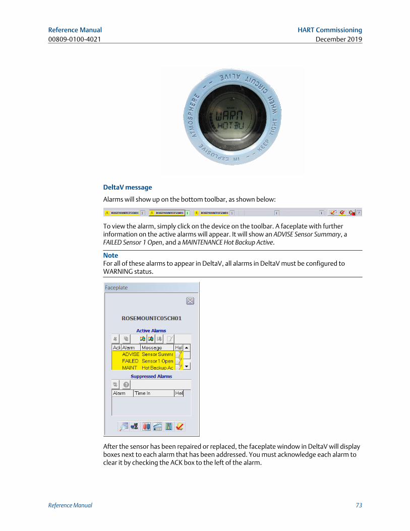
DeltaV message
Alarms will show up on the bottom toolbar, as shown below:
To view the alarm, simply click on the device on the toolbar. A faceplate with furtherinformation on the active alarms will appear. It will show an ADVISE Sensor Summary, aFAILED Sensor 1 Open, and a MAINTENANCE Hot Backup Active.
NoteFor all of these alarms to appear in DeltaV, all alarms in DeltaV must be configured toWARNING status.
After the sensor has been repaired or replaced, the faceplate window in DeltaV will displayboxes next to each alarm that has been addressed. You must acknowledge each alarm toclear it by checking the ACK box to the left of the alarm.
Reference Manual HART Commissioning00809-0100-4021 December 2019
Reference Manual 73
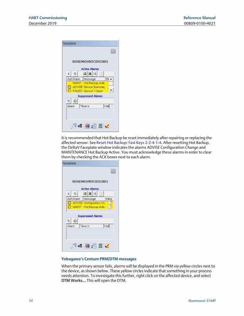
It is recommended that Hot Backup be reset immediately after repairing or replacing theaffected sensor. See Reset Hot Backup: Fast Keys 2-2-4-1-4. After resetting Hot Backup,the DeltaV Faceplate window indicates the alarms ADVISE Configuration Change andMAINTENANCE Hot Backup Active. You must acknowledge these alarms in order to clearthem by checking the ACK boxes next to each alarm.
Yokogawa’s Centum PRM/DTM messages
When the primary sensor fails, alarms will be displayed in the PRM via yellow circles next tothe device, as shown below. These yellow circles indicate that something in your processneeds attention. To investigate this further, right click on the affected device, and selectDTM Works… This will open the DTM.
HART Commissioning Reference ManualDecember 2019 00809-0100-4021
74 Rosemount 3144P
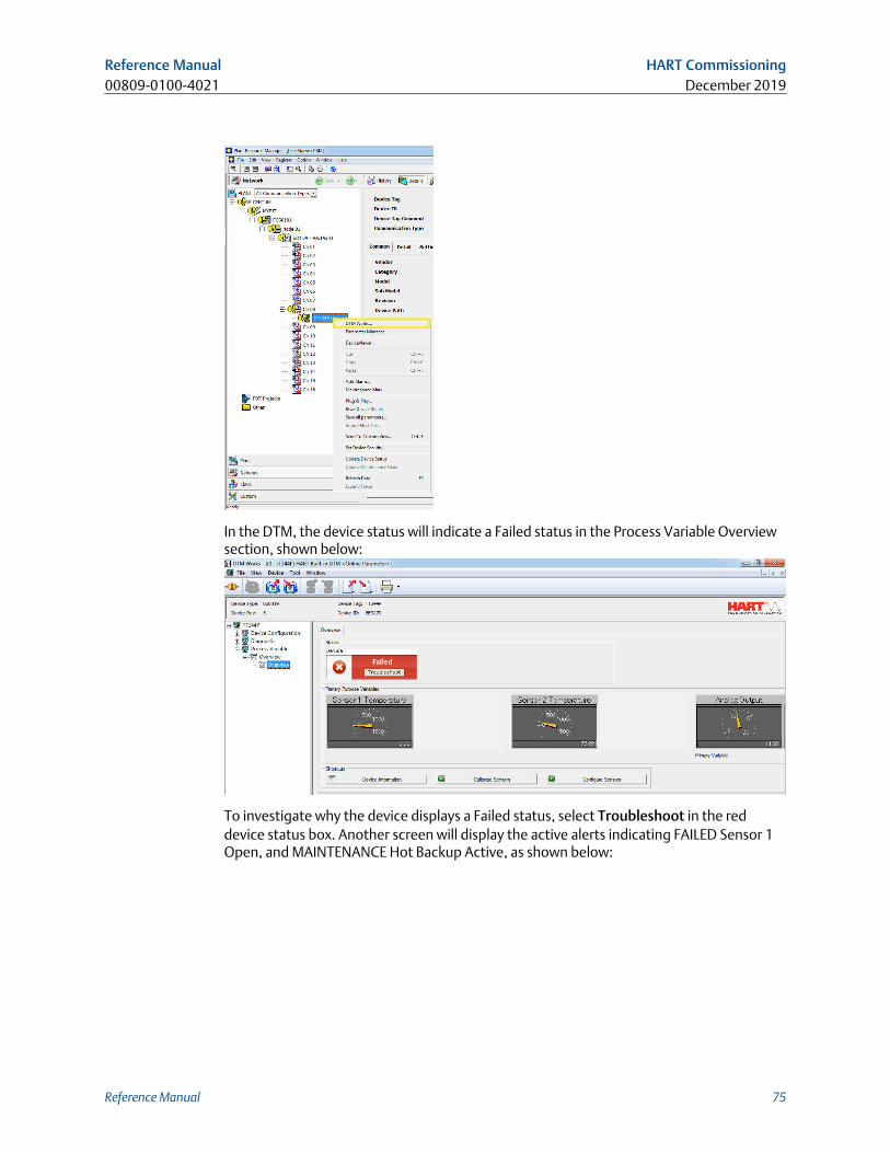
In the DTM, the device status will indicate a Failed status in the Process Variable Overviewsection, shown below:
To investigate why the device displays a Failed status, select Troubleshoot in the reddevice status box. Another screen will display the active alerts indicating FAILED Sensor 1Open, and MAINTENANCE Hot Backup Active, as shown below:
Reference Manual HART Commissioning00809-0100-4021 December 2019
Reference Manual 75
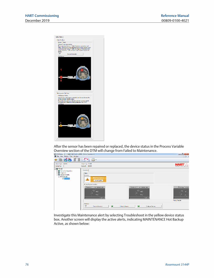
After the sensor has been repaired or replaced, the device status in the Process VariableOverview section of the DTM will change from Failed to Maintenance.
Investigate this Maintenance alert by selecting Troubleshoot in the yellow device statusbox. Another screen will display the active alerts, indicating MAINTENANCE Hot BackupActive, as shown below:
HART Commissioning Reference ManualDecember 2019 00809-0100-4021
76 Rosemount 3144P
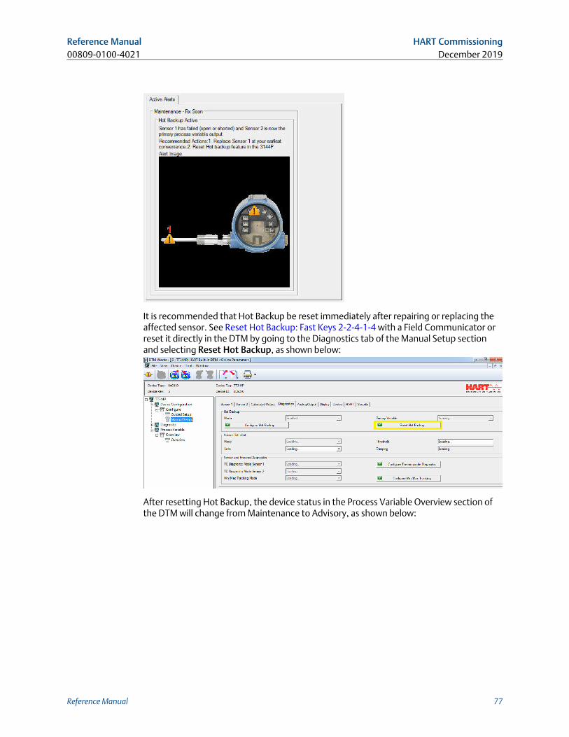
It is recommended that Hot Backup be reset immediately after repairing or replacing theaffected sensor. See Reset Hot Backup: Fast Keys 2-2-4-1-4 with a Field Communicator orreset it directly in the DTM by going to the Diagnostics tab of the Manual Setup sectionand selecting Reset Hot Backup, as shown below:
After resetting Hot Backup, the device status in the Process Variable Overview section ofthe DTM will change from Maintenance to Advisory, as shown below:
Reference Manual HART Commissioning00809-0100-4021 December 2019
Reference Manual 77
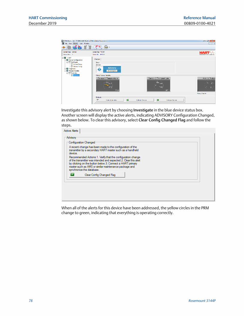
Investigate this advisory alert by choosing Investigate in the blue device status box.Another screen will display the active alerts, indicating ADVISORY Configuration Changed,as shown below. To clear this advisory, select Clear Config Changed Flag and follow thesteps.
When all of the alerts for this device have been addressed, the yellow circles in the PRMchange to green, indicating that everything is operating correctly.
HART Commissioning Reference ManualDecember 2019 00809-0100-4021
78 Rosemount 3144P
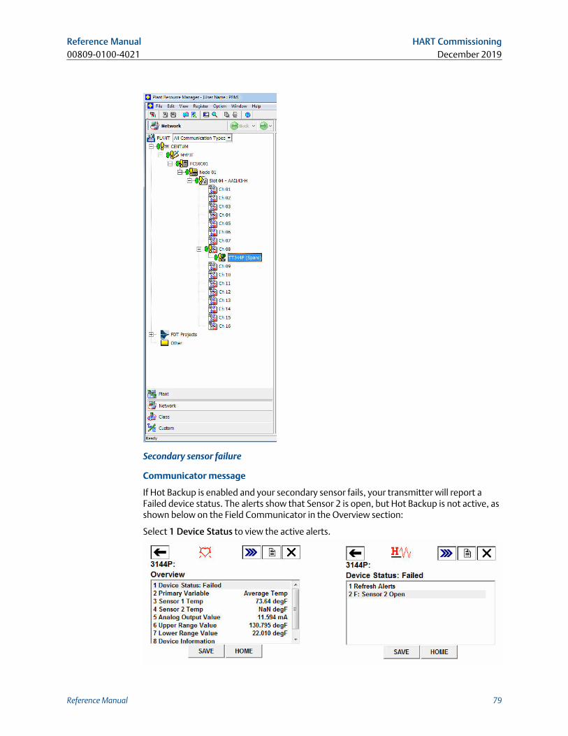
Secondary sensor failure
Communicator message
If Hot Backup is enabled and your secondary sensor fails, your transmitter will report aFailed device status. The alerts show that Sensor 2 is open, but Hot Backup is not active, asshown below on the Field Communicator in the Overview section:
Select 1 Device Status to view the active alerts.
Reference Manual HART Commissioning00809-0100-4021 December 2019
Reference Manual 79
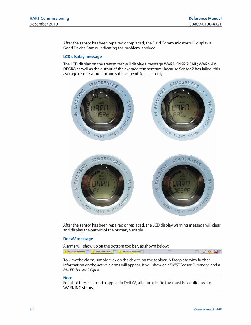
After the sensor has been repaired or replaced, the Field Communicator will display aGood Device Status, indicating the problem is solved.
LCD display message
The LCD display on the transmitter will display a message WARN SNSR 2 FAIL; WARN AVDEGRA as well as the output of the average temperature. Because Sensor 2 has failed, thisaverage temperature output is the value of Sensor 1 only.
After the sensor has been repaired or replaced, the LCD display warning message will clearand display the output of the primary variable.
DeltaV message
Alarms will show up on the bottom toolbar, as shown below:
To view the alarm, simply click on the device on the toolbar. A faceplate with furtherinformation on the active alarms will appear. It will show an ADVISE Sensor Summary, and aFAILED Sensor 2 Open.
NoteFor all of these alarms to appear in DeltaV, all alarms in DeltaV must be configured toWARNING status.
HART Commissioning Reference ManualDecember 2019 00809-0100-4021
80 Rosemount 3144P
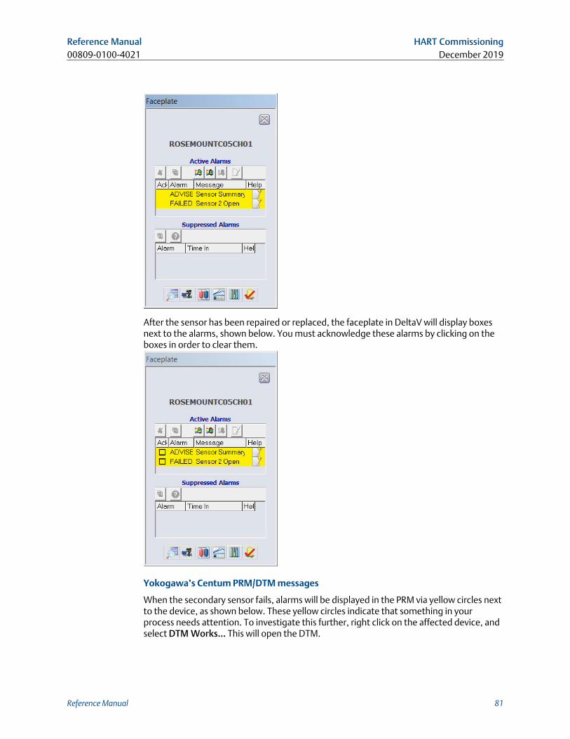
After the sensor has been repaired or replaced, the faceplate in DeltaV will display boxesnext to the alarms, shown below. You must acknowledge these alarms by clicking on theboxes in order to clear them.
Yokogawa’s Centum PRM/DTM messages
When the secondary sensor fails, alarms will be displayed in the PRM via yellow circles nextto the device, as shown below. These yellow circles indicate that something in yourprocess needs attention. To investigate this further, right click on the affected device, andselect DTM Works… This will open the DTM.
Reference Manual HART Commissioning00809-0100-4021 December 2019
Reference Manual 81
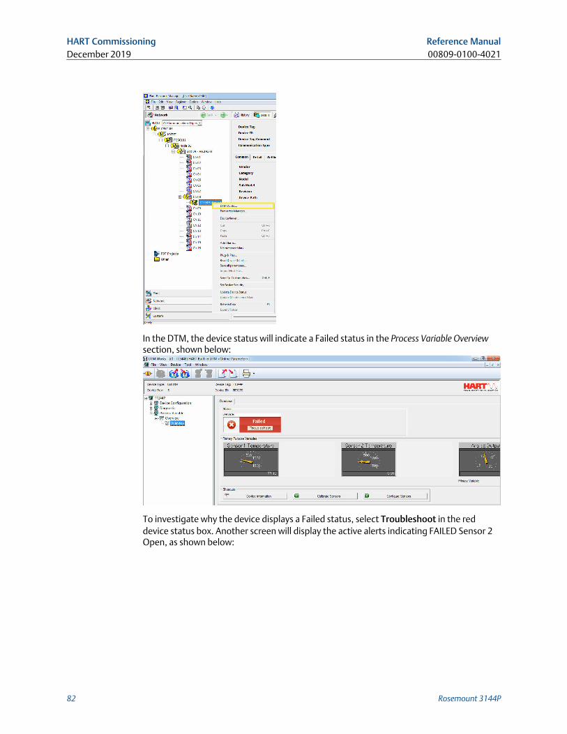
In the DTM, the device status will indicate a Failed status in the Process Variable Overviewsection, shown below:
To investigate why the device displays a Failed status, select Troubleshoot in the reddevice status box. Another screen will display the active alerts indicating FAILED Sensor 2Open, as shown below:
HART Commissioning Reference ManualDecember 2019 00809-0100-4021
82 Rosemount 3144P
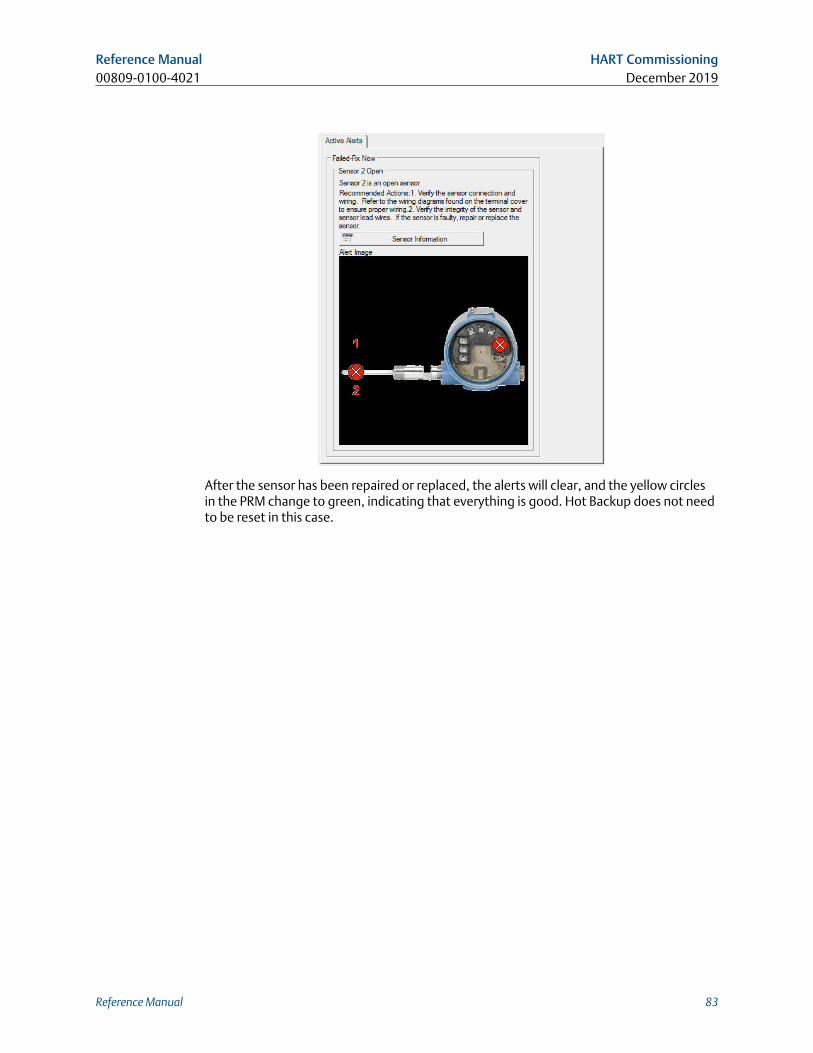
After the sensor has been repaired or replaced, the alerts will clear, and the yellow circlesin the PRM change to green, indicating that everything is good. Hot Backup does not needto be reset in this case.
Reference Manual HART Commissioning00809-0100-4021 December 2019
Reference Manual 83
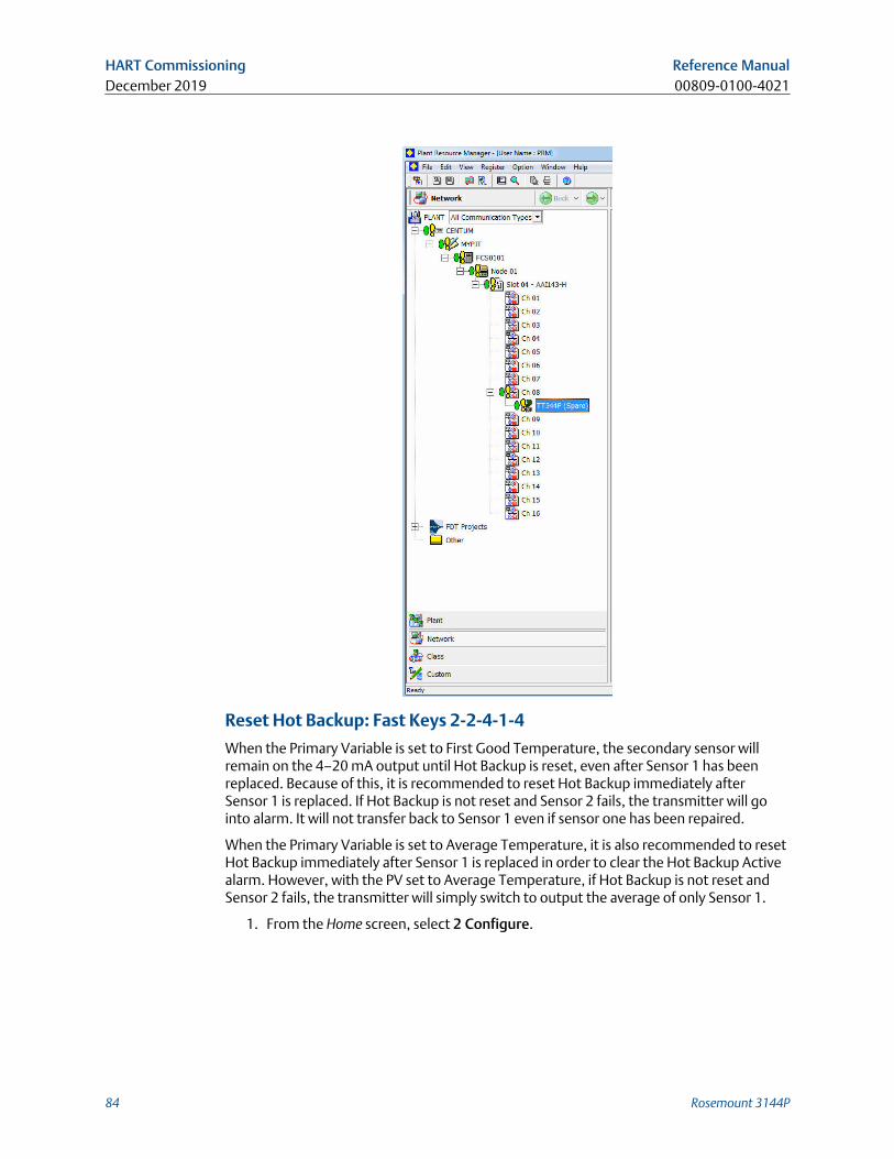
Reset Hot Backup: Fast Keys 2-2-4-1-4
When the Primary Variable is set to First Good Temperature, the secondary sensor willremain on the 4–20 mA output until Hot Backup is reset, even after Sensor 1 has beenreplaced. Because of this, it is recommended to reset Hot Backup immediately afterSensor 1 is replaced. If Hot Backup is not reset and Sensor 2 fails, the transmitter will gointo alarm. It will not transfer back to Sensor 1 even if sensor one has been repaired.
When the Primary Variable is set to Average Temperature, it is also recommended to resetHot Backup immediately after Sensor 1 is replaced in order to clear the Hot Backup Activealarm. However, with the PV set to Average Temperature, if Hot Backup is not reset andSensor 2 fails, the transmitter will simply switch to output the average of only Sensor 1.
1. From the Home screen, select 2 Configure.
HART Commissioning Reference ManualDecember 2019 00809-0100-4021
84 Rosemount 3144P
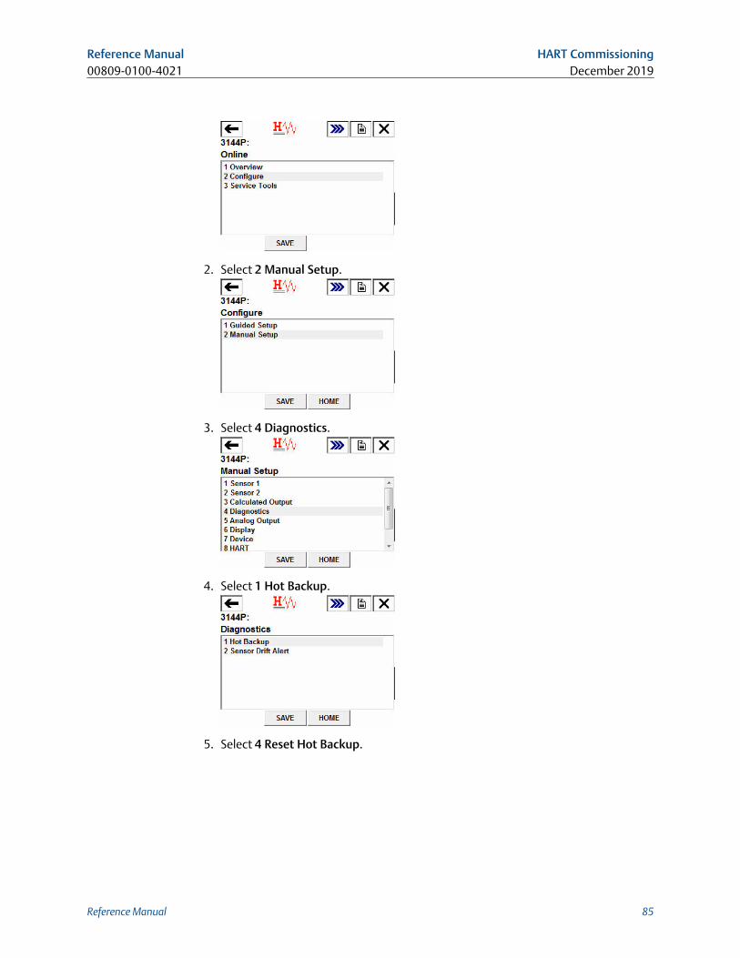
2. Select 2 Manual Setup.
3. Select 4 Diagnostics.
4. Select 1 Hot Backup.
5. Select 4 Reset Hot Backup.
Reference Manual HART Commissioning00809-0100-4021 December 2019
Reference Manual 85
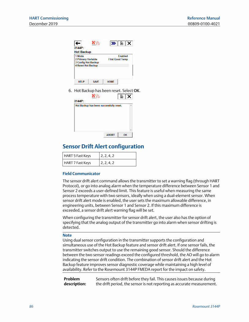
6. Hot Backup has been reset. Select OK.
Sensor Drift Alert configuration
HART 5 Fast Keys 2, 2, 4, 2
HART 7 Fast Keys 2, 2, 4, 2
Field Communicator
The sensor drift alert command allows the transmitter to set a warning flag (through HARTProtocol), or go into analog alarm when the temperature difference between Sensor 1 andSensor 2 exceeds a user-defined limit. This feature is useful when measuring the sameprocess temperature with two sensors, ideally when using a dual-element sensor. Whensensor drift alert mode is enabled, the user sets the maximum allowable difference, inengineering units, between Sensor 1 and Sensor 2. If this maximum difference isexceeded, a sensor drift alert warning flag will be set.
When configuring the transmitter for sensor drift alert, the user also has the option ofspecifying that the analog output of the transmitter go into alarm when sensor drifting isdetected.
NoteUsing dual sensor configuration in the transmitter supports the configuration andsimultaneous use of the Hot Backup feature and sensor drift alert. If one sensor fails, thetransmitter switches output to use the remaining good sensor. Should the differencebetween the two sensor readings exceed the configured threshold, the AO will go to alarmindicating the sensor drift condition. The combination of sensor drift alert and the HotBackup feature improves sensor diagnostic coverage while maintaining a high level ofavailability. Refer to the Rosemount 3144P FMEDA report for the impact on safety.
Problemdescription:
Sensors often drift before they fail. This causes issues because duringthe drift period, the sensor is not reporting as accurate measurement.
HART Commissioning Reference ManualDecember 2019 00809-0100-4021
86 Rosemount 3144P
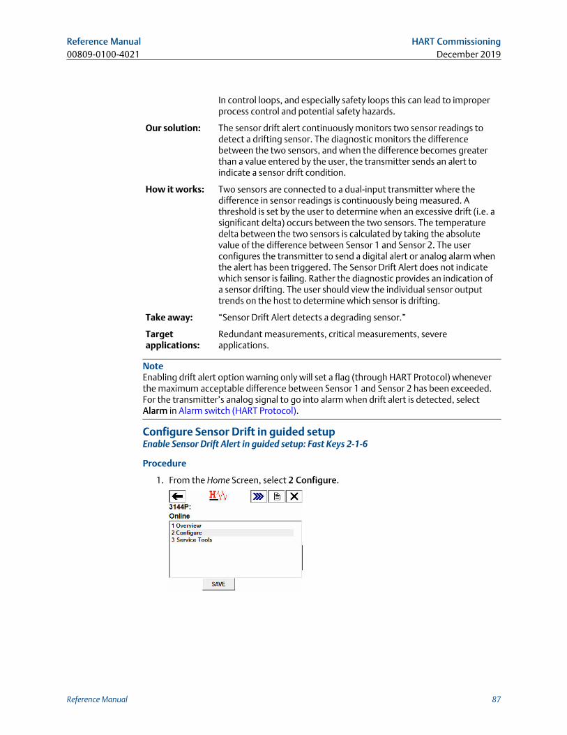
In control loops, and especially safety loops this can lead to improperprocess control and potential safety hazards.
Our solution: The sensor drift alert continuously monitors two sensor readings todetect a drifting sensor. The diagnostic monitors the differencebetween the two sensors, and when the difference becomes greaterthan a value entered by the user, the transmitter sends an alert toindicate a sensor drift condition.
How it works: Two sensors are connected to a dual-input transmitter where thedifference in sensor readings is continuously being measured. Athreshold is set by the user to determine when an excessive drift (i.e. asignificant delta) occurs between the two sensors. The temperaturedelta between the two sensors is calculated by taking the absolutevalue of the difference between Sensor 1 and Sensor 2. The userconfigures the transmitter to send a digital alert or analog alarm whenthe alert has been triggered. The Sensor Drift Alert does not indicatewhich sensor is failing. Rather the diagnostic provides an indication ofa sensor drifting. The user should view the individual sensor outputtrends on the host to determine which sensor is drifting.
Take away: “Sensor Drift Alert detects a degrading sensor.”
Targetapplications:
Redundant measurements, critical measurements, severeapplications.
NoteEnabling drift alert option warning only will set a flag (through HART Protocol) wheneverthe maximum acceptable difference between Sensor 1 and Sensor 2 has been exceeded.For the transmitter’s analog signal to go into alarm when drift alert is detected, selectAlarm in Alarm switch (HART Protocol).
Configure Sensor Drift in guided setupEnable Sensor Drift Alert in guided setup: Fast Keys 2-1-6
Procedure
1. From the Home Screen, select 2 Configure.
Reference Manual HART Commissioning00809-0100-4021 December 2019
Reference Manual 87
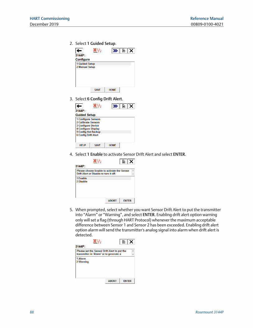
2. Select 1 Guided Setup.
3. Select 6 Config Drift Alert.
4. Select 1 Enable to activate Sensor Drift Alert and select ENTER.
5. When prompted, select whether you want Sensor Drift Alert to put the transmitterinto “Alarm” or “Warning”, and select ENTER. Enabling drift alert option warningonly will set a flag (through HART Protocol) whenever the maximum acceptabledifference between Sensor 1 and Sensor 2 has been exceeded. Enabling drift alertoption alarm will send the transmitter's analog signal into alarm when drift alert isdetected.
HART Commissioning Reference ManualDecember 2019 00809-0100-4021
88 Rosemount 3144P
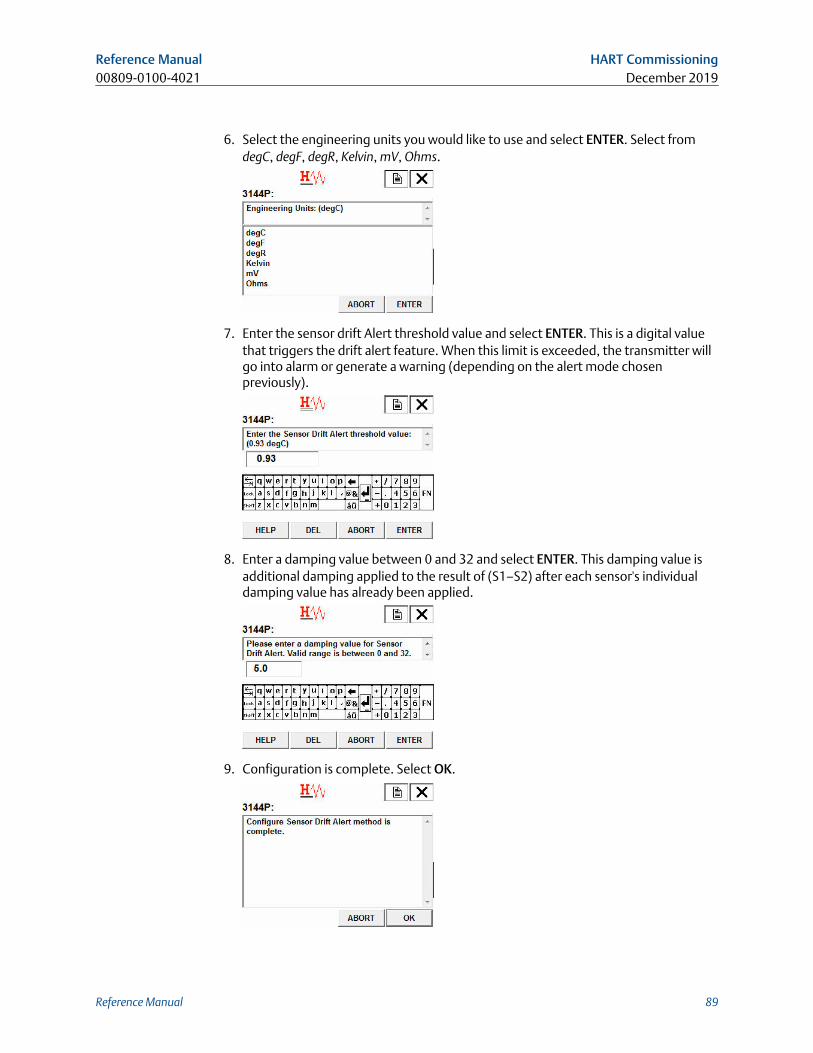
6. Select the engineering units you would like to use and select ENTER. Select fromdegC, degF, degR, Kelvin, mV, Ohms.
7. Enter the sensor drift Alert threshold value and select ENTER. This is a digital valuethat triggers the drift alert feature. When this limit is exceeded, the transmitter willgo into alarm or generate a warning (depending on the alert mode chosenpreviously).
8. Enter a damping value between 0 and 32 and select ENTER. This damping value isadditional damping applied to the result of (S1–S2) after each sensor's individualdamping value has already been applied.
9. Configuration is complete. Select OK.
Reference Manual HART Commissioning00809-0100-4021 December 2019
Reference Manual 89
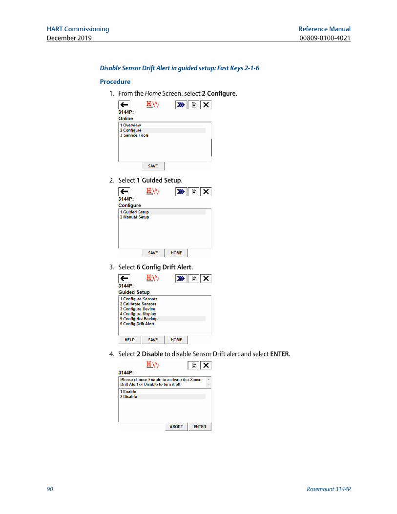
Disable Sensor Drift Alert in guided setup: Fast Keys 2-1-6
Procedure
1. From the Home Screen, select 2 Configure.
2. Select 1 Guided Setup.
3. Select 6 Config Drift Alert.
4. Select 2 Disable to disable Sensor Drift alert and select ENTER.
HART Commissioning Reference ManualDecember 2019 00809-0100-4021
90 Rosemount 3144P
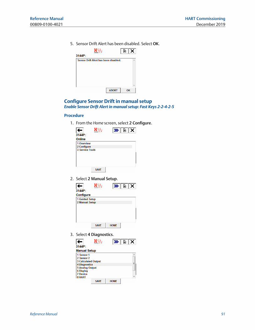
5. Sensor Drift Alert has been disabled. Select OK.
Configure Sensor Drift in manual setupEnable Sensor Drift Alert in manual setup: Fast Keys 2-2-4-2-5
Procedure
1. From the Home screen, select 2 Configure.
2. Select 2 Manual Setup.
3. Select 4 Diagnostics.
Reference Manual HART Commissioning00809-0100-4021 December 2019
Reference Manual 91
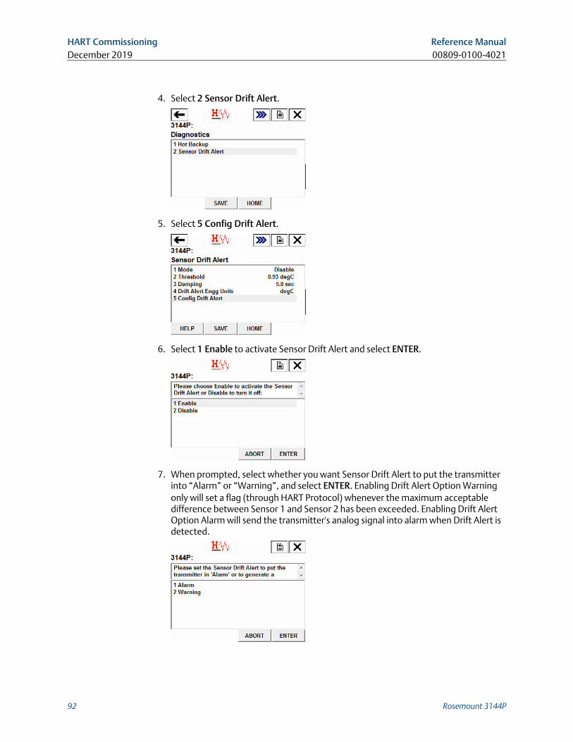
4. Select 2 Sensor Drift Alert.
5. Select 5 Config Drift Alert.
6. Select 1 Enable to activate Sensor Drift Alert and select ENTER.
7. When prompted, select whether you want Sensor Drift Alert to put the transmitterinto “Alarm” or “Warning”, and select ENTER. Enabling Drift Alert Option Warningonly will set a flag (through HART Protocol) whenever the maximum acceptabledifference between Sensor 1 and Sensor 2 has been exceeded. Enabling Drift AlertOption Alarm will send the transmitter's analog signal into alarm when Drift Alert isdetected.
HART Commissioning Reference ManualDecember 2019 00809-0100-4021
92 Rosemount 3144P
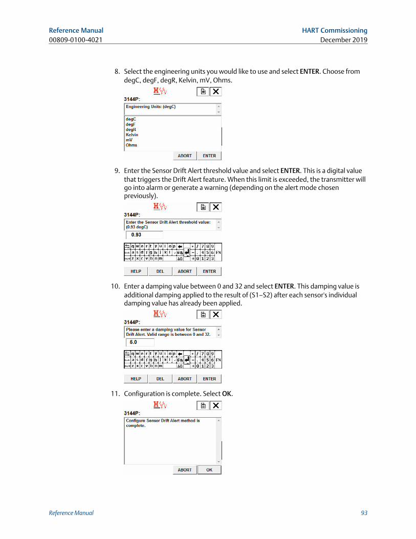
8. Select the engineering units you would like to use and select ENTER. Choose fromdegC, degF, degR, Kelvin, mV, Ohms.
9. Enter the Sensor Drift Alert threshold value and select ENTER. This is a digital valuethat triggers the Drift Alert feature. When this limit is exceeded, the transmitter willgo into alarm or generate a warning (depending on the alert mode chosenpreviously).
10. Enter a damping value between 0 and 32 and select ENTER. This damping value isadditional damping applied to the result of (S1–S2) after each sensor's individualdamping value has already been applied.
11. Configuration is complete. Select OK.
Reference Manual HART Commissioning00809-0100-4021 December 2019
Reference Manual 93
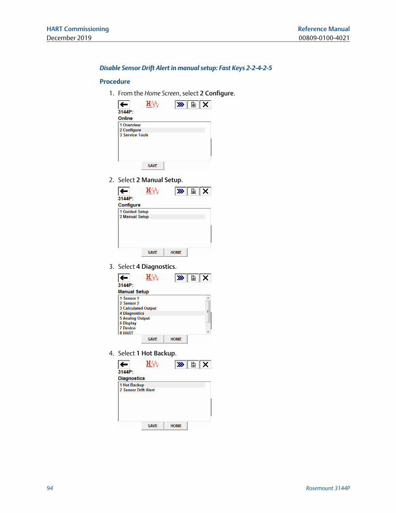
Disable Sensor Drift Alert in manual setup: Fast Keys 2-2-4-2-5
Procedure
1. From the Home Screen, select 2 Configure.
2. Select 2 Manual Setup.
3. Select 4 Diagnostics.
4. Select 1 Hot Backup.
HART Commissioning Reference ManualDecember 2019 00809-0100-4021
94 Rosemount 3144P
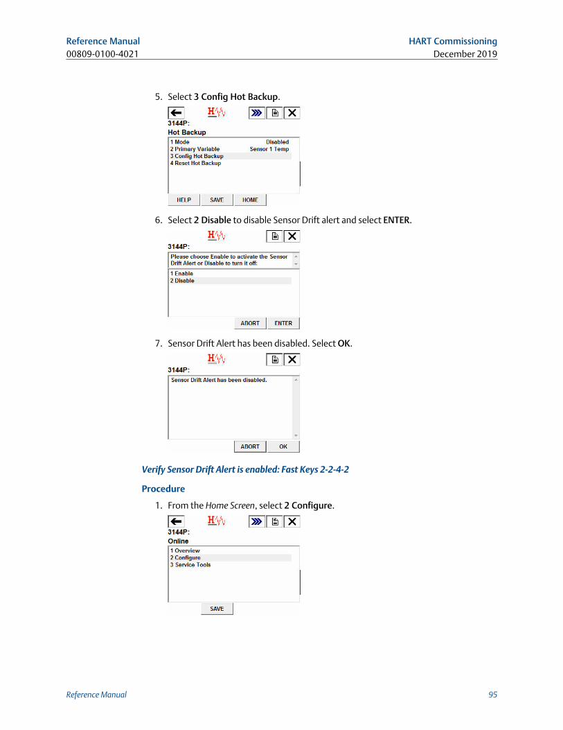
5. Select 3 Config Hot Backup.
6. Select 2 Disable to disable Sensor Drift alert and select ENTER.
7. Sensor Drift Alert has been disabled. Select OK.
Verify Sensor Drift Alert is enabled: Fast Keys 2-2-4-2
Procedure
1. From the Home Screen, select 2 Configure.
Reference Manual HART Commissioning00809-0100-4021 December 2019
Reference Manual 95
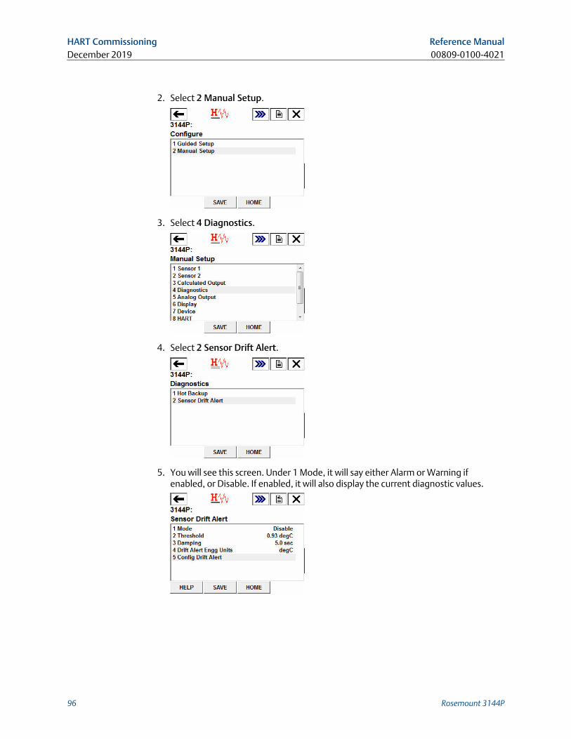
2. Select 2 Manual Setup.
3. Select 4 Diagnostics.
4. Select 2 Sensor Drift Alert.
5. You will see this screen. Under 1 Mode, it will say either Alarm or Warning ifenabled, or Disable. If enabled, it will also display the current diagnostic values.
HART Commissioning Reference ManualDecember 2019 00809-0100-4021
96 Rosemount 3144P
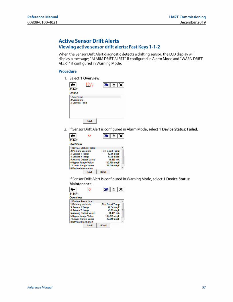
Active Sensor Drift AlertsViewing active sensor drift alerts: Fast Keys 1-1-2
When the Sensor Drift Alert diagnostic detects a drifting sensor, the LCD display willdisplay a message; “ALARM DRIFT ALERT” if configured in Alarm Mode and “WARN DRIFTALERT” if configured in Warning Mode.
Procedure
1. Select 1 Overview.
2. If Sensor Drift Alert is configured in Alarm Mode, select 1 Device Status: Failed.
If Sensor Drift Alert is configured in Warning Mode, select 1 Device Status:Maintenance.
Reference Manual HART Commissioning00809-0100-4021 December 2019
Reference Manual 97
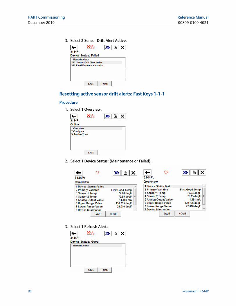
3. Select 2 Sensor Drift Alert Active.
Resetting active sensor drift alerts: Fast Keys 1-1-1
Procedure
1. Select 1 Overview.
2. Select 1 Device Status: (Maintenance or Failed).
3. Select 1 Refresh Alerts.
HART Commissioning Reference ManualDecember 2019 00809-0100-4021
98 Rosemount 3144P
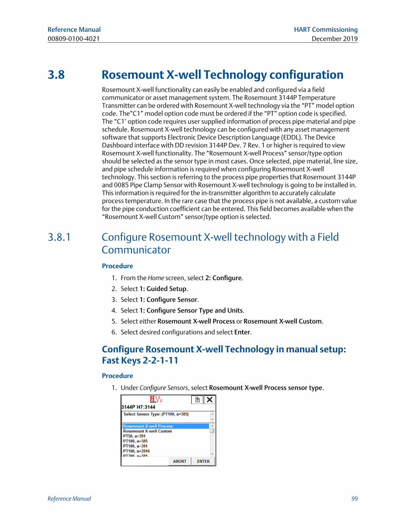
3.8 Rosemount X-well Technology configurationRosemount X-well functionality can easily be enabled and configured via a fieldcommunicator or asset management system. The Rosemount 3144P TemperatureTransmitter can be ordered with Rosemount X-well technology via the “PT” model optioncode. The”C1” model option code must be ordered if the “PT” option code is specified.The “C1’ option code requires user supplied information of process pipe material and pipeschedule. Rosemount X-well technology can be configured with any asset managementsoftware that supports Electronic Device Description Language (EDDL). The DeviceDashboard interface with DD revision 3144P Dev. 7 Rev. 1 or higher is required to viewRosemount X-well functionality. The “Rosemount X-well Process” sensor/type optionshould be selected as the sensor type in most cases. Once selected, pipe material, line size,and pipe schedule information is required when configuring Rosemount X-welltechnology. This section is referring to the process pipe properties that Rosemount 3144Pand 0085 Pipe Clamp Sensor with Rosemount X-well technology is going to be installed in.This information is required for the in-transmitter algorithm to accurately calculateprocess temperature. In the rare case that the process pipe is not available, a custom valuefor the pipe conduction coefficient can be entered. This field becomes available when the“Rosemount X-well Custom” sensor/type option is selected.
3.8.1 Configure Rosemount X-well technology with a FieldCommunicatorProcedure
1. From the Home screen, select 2: Configure.
2. Select 1: Guided Setup.
3. Select 1: Configure Sensor.
4. Select 1: Configure Sensor Type and Units.
5. Select either Rosemount X-well Process or Rosemount X-well Custom.
6. Select desired configurations and select Enter.
Configure Rosemount X-well Technology in manual setup:Fast Keys 2-2-1-11
Procedure
1. Under Configure Sensors, select Rosemount X-well Process sensor type.
Reference Manual HART Commissioning00809-0100-4021 December 2019
Reference Manual 99
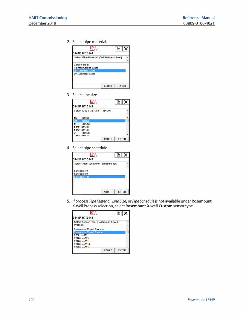
2. Select pipe material.
3. Select line size.
4. Select pipe schedule.
5. If process Pipe Material, Line Size, or Pipe Schedule is not available under RosemountX-well Process selection, select Rosemount X-well Custom sensor type.
HART Commissioning Reference ManualDecember 2019 00809-0100-4021
100 Rosemount 3144P
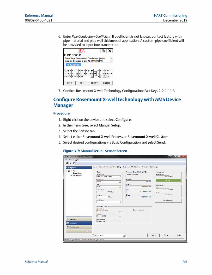
6. Enter Pipe Conduction Coefficient. If coefficient is not known, contact factory withpipe material and pipe wall thickness of application. A custom pipe coefficient willbe provided to input into transmitter.
7. Confirm Rosemount X-well Technology Configuration: Fast Keys 2-2-1-11-3
Configure Rosemount X-well technology with AMS DeviceManager
Procedure
1. Right click on the device and select Configure.
2. In the menu tree, select Manual Setup.
3. Select the Sensor tab.
4. Select either Rosemount X-well Process or Rosemount X-well Custom.
5. Select desired configurations via Basic Configuration and select Send.
Figure 3-7: Manual Setup - Sensor Screen
Reference Manual HART Commissioning00809-0100-4021 December 2019
Reference Manual 101
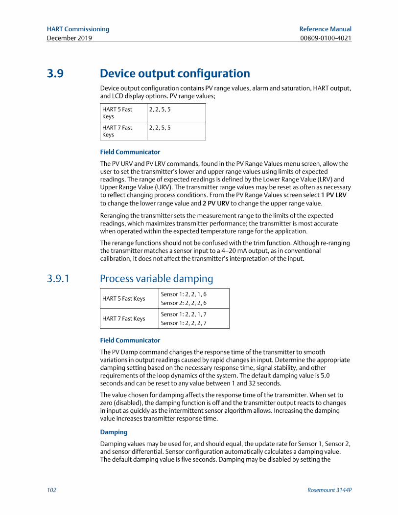
3.9 Device output configurationDevice output configuration contains PV range values, alarm and saturation, HART output,and LCD display options. PV range values;
HART 5 FastKeys
2, 2, 5, 5
HART 7 FastKeys
2, 2, 5, 5
Field Communicator
The PV URV and PV LRV commands, found in the PV Range Values menu screen, allow theuser to set the transmitter’s lower and upper range values using limits of expectedreadings. The range of expected readings is defined by the Lower Range Value (LRV) andUpper Range Value (URV). The transmitter range values may be reset as often as necessaryto reflect changing process conditions. From the PV Range Values screen select 1 PV LRVto change the lower range value and 2 PV URV to change the upper range value.
Reranging the transmitter sets the measurement range to the limits of the expectedreadings, which maximizes transmitter performance; the transmitter is most accuratewhen operated within the expected temperature range for the application.
The rerange functions should not be confused with the trim function. Although re-rangingthe transmitter matches a sensor input to a 4–20 mA output, as in conventionalcalibration, it does not affect the transmitter’s interpretation of the input.
3.9.1 Process variable damping
HART 5 Fast KeysSensor 1: 2, 2, 1, 6
Sensor 2: 2, 2, 2, 6
HART 7 Fast KeysSensor 1: 2, 2, 1, 7
Sensor 1: 2, 2, 2, 7
Field Communicator
The PV Damp command changes the response time of the transmitter to smoothvariations in output readings caused by rapid changes in input. Determine the appropriatedamping setting based on the necessary response time, signal stability, and otherrequirements of the loop dynamics of the system. The default damping value is 5.0seconds and can be reset to any value between 1 and 32 seconds.
The value chosen for damping affects the response time of the transmitter. When set tozero (disabled), the damping function is off and the transmitter output reacts to changesin input as quickly as the intermittent sensor algorithm allows. Increasing the dampingvalue increases transmitter response time.
Damping
Damping values may be used for, and should equal, the update rate for Sensor 1, Sensor 2,and sensor differential. Sensor configuration automatically calculates a damping value.The default damping value is five seconds. Damping may be disabled by setting the
HART Commissioning Reference ManualDecember 2019 00809-0100-4021
102 Rosemount 3144P
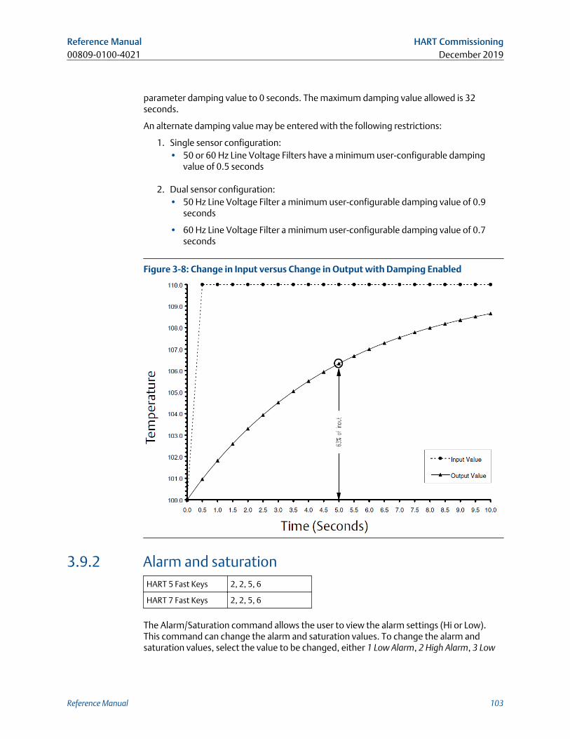
parameter damping value to 0 seconds. The maximum damping value allowed is 32seconds.
An alternate damping value may be entered with the following restrictions:
1. Single sensor configuration:• 50 or 60 Hz Line Voltage Filters have a minimum user-configurable damping
value of 0.5 seconds
2. Dual sensor configuration:• 50 Hz Line Voltage Filter a minimum user-configurable damping value of 0.9
seconds
• 60 Hz Line Voltage Filter a minimum user-configurable damping value of 0.7seconds
Figure 3-8: Change in Input versus Change in Output with Damping Enabled
3.9.2 Alarm and saturationHART 5 Fast Keys 2, 2, 5, 6
HART 7 Fast Keys 2, 2, 5, 6
The Alarm/Saturation command allows the user to view the alarm settings (Hi or Low).This command can change the alarm and saturation values. To change the alarm andsaturation values, select the value to be changed, either 1 Low Alarm, 2 High Alarm, 3 Low
Reference Manual HART Commissioning00809-0100-4021 December 2019
Reference Manual 103
Sat, 4 High Sat, or 5 Preset Alarms and enter the desired new value which must fall withinthe guidelines below:
• The low alarm value must be between 3.50 and 3.75 mA
• The high alarm value must be between 21.0 and 23.0 mA
The low saturation level must be between the low alarm value plus 0.1 mA and 3.9 mA forthe standard HART transmitter. For the safety certified transmitter, the lowest saturationsetting is 3.7 mA and the highest is 20.9 mA.
Example: The low alarm value has been set to 3.7 mA. Therefore, the low saturation level,S, must be 3.8 ≤ S ≤ 3.9 mA.
The high saturation level must be between 20.5 and 20.9 mA.
Preset alarms can either be 1 Rosemount or 2 NAMUR-compliant. Use the failure modeswitch on the front side of the electronics to set whether the output will be driven to highor low alarm in the case of failure.
3.9.3 HART outputHART 5 Fast Keys 2, 2, 8
HART 7 Fast Keys 2, 2, 8
The HART Output command allows the user to make changes to the multidrop address,initiate burst mode, or make changes to the burst options.
3.9.4 LCD display optionsHART 5 Fast Keys 2, 2, 6
HART 7 Fast Keys 2, 2, 6
The LCD display option command sets the meter options, including engineering units anddecimal point. Change the LCD display settings to reflect necessary configurationparameters when adding a LCD display or reconfiguring the transmitter. Transmitterswithout LCD displays are shipped with the meter configuration set to “Not Used.”
3.10 Device informationAccess the transmitter information variables online using the Field Communicator or othersuitable communications device. The following is a list of transmitter informationvariables, including device identifiers, factory-set configuration variables, and otherinformation. A description of each variable, the corresponding fast key sequence, and areview are provided.
3.10.1 TagHART 5 Fast Keys 2, 2, 7, 1, 1
HART 7 Fast Keys 2, 2, 7, 1, 1
HART Commissioning Reference ManualDecember 2019 00809-0100-4021
104 Rosemount 3144P
The Tag variable is the easiest way to identify and distinguish between transmitters inmulti-transmitter environments. Use it to label transmitters electronically according to therequirements of the application. The tag defined is automatically displayed when a HART-based Communicator establishes contact with the transmitter at power-up. The tag maybe up to eight characters long and has no impact on the primary variable readings of thetransmitter.
3.10.2 Long TagHART 5 Fast Key HART 7 only
HART 7 Fast Key 2, 2, 7, 1, 2
The Long Tag is similar to Tag. The long tag is different in that the Long tag can be up to 32Characters instead of the eight characters in traditional Tag.
3.10.3 DateHART 5 Fast Keys 2, 2, 7, 1, 2
HART 7 Fast Keys 2, 2, 7, 1, 3
The Date command is a user-defined variable that provides a place to save the date of thelast revision of configuration information. It has no impact on the operation of thetransmitter or the Field Communicator.
3.10.4 DescriptorHART 5 Fast Keys 2, 2, 7, 1, 3
HART 7 Fast Keys 2, 2, 7, 1, 4
The Descriptor variable provides a longer user-defined electronic label to assist with morespecific transmitter identification than is available with the tag variable. The descriptormay be up to 16 characters long and has no impact on the operation of the transmitter orthe Field Communicator.
3.10.5 MessageHART 5 Fast Keys 2, 2, 7, 1, 4
HART 7 Fast Keys 2, 2, 7, 1, 5
The Message variable provides the most specific user-defined means for identifyingindividual transmitters in multi-transmitter environments. It allows for 32 characters ofinformation and is stored with the other configuration data. The message variable has noimpact on the operation of the transmitter or the Field Communicator.
Reference Manual HART Commissioning00809-0100-4021 December 2019
Reference Manual 105
3.11 Measurement filtering
3.11.1 50/60 Hz FilterHART 5 Fast Keys 2, 2, 7, 5, 1
HART 7 Fast Keys 2, 2, 7, 5, 1
The 50/60 Hz Filter (also known as Line Voltage Filter or AC Power Filter) variable sets thetransmitter electronic filter to reject the AC power supply frequency in the plant. The 60 or50 Hz mode can be chosen. The factory default for this setting is 60 Hz.
NoteIn high noise environments, normal mode is recommended.
3.11.2 Master ResetHART 5 Fast Keys 2, 2, 7, 6
HART 7 Fast Keys 2, 2, 7, 6
Master Reset resets the electronics without actually powering down the unit. It does notreturn the transmitter to the original factory configuration.
3.11.3 Intermittent Sensor DetectHART 5 Fast Keys 2, 2, 7, 5, 2
HART 7 Fast Keys 2, 2, 7, 5, 2
The following steps indicate how to turn the Intermittent Sensor Detect (also known asTransient Filter) feature ON or OFF. When the transmitter is connected to a FieldCommunicator, use the Fast Key sequence and select ON (normal setting) or OFF.
3.11.4 Intermittent thresholdThe threshold value can be changed from the default value of 0.2 percent. Turning theIntermittent Sensor Detect feature OFF or leaving it ON and increasing the threshold valueabove the default does not affect the time needed for the transmitter to output thecorrect alarm signal after detecting a true open sensor condition. However, thetransmitter may briefly output a false temperature reading for up to one update in eitherdirection (see Figure 3-10) up to the threshold value (100 percent of sensor limits ifIntermittent Sensor Detect is OFF). Unless rapid response rate is necessary, the suggestedsetting of the Intermittent Sensor Detect mechanism is ON with 0.2 percent threshold.
HART Commissioning Reference ManualDecember 2019 00809-0100-4021
106 Rosemount 3144P
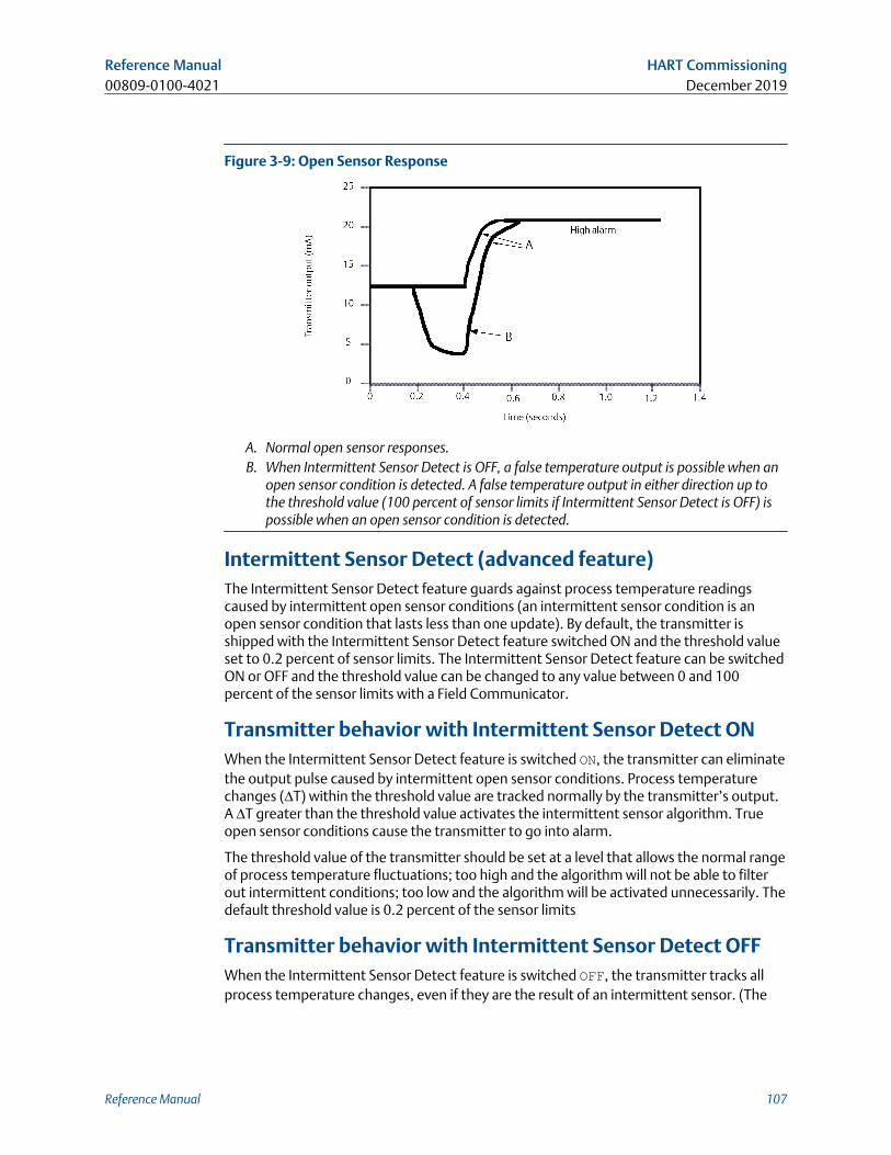
Figure 3-9: Open Sensor Response
A. Normal open sensor responses.B. When Intermittent Sensor Detect is OFF, a false temperature output is possible when an
open sensor condition is detected. A false temperature output in either direction up tothe threshold value (100 percent of sensor limits if Intermittent Sensor Detect is OFF) ispossible when an open sensor condition is detected.
Intermittent Sensor Detect (advanced feature)The Intermittent Sensor Detect feature guards against process temperature readingscaused by intermittent open sensor conditions (an intermittent sensor condition is anopen sensor condition that lasts less than one update). By default, the transmitter isshipped with the Intermittent Sensor Detect feature switched ON and the threshold valueset to 0.2 percent of sensor limits. The Intermittent Sensor Detect feature can be switchedON or OFF and the threshold value can be changed to any value between 0 and 100percent of the sensor limits with a Field Communicator.
Transmitter behavior with Intermittent Sensor Detect ONWhen the Intermittent Sensor Detect feature is switched ON, the transmitter can eliminatethe output pulse caused by intermittent open sensor conditions. Process temperaturechanges (ΔT) within the threshold value are tracked normally by the transmitter’s output.A ΔT greater than the threshold value activates the intermittent sensor algorithm. Trueopen sensor conditions cause the transmitter to go into alarm.
The threshold value of the transmitter should be set at a level that allows the normal rangeof process temperature fluctuations; too high and the algorithm will not be able to filterout intermittent conditions; too low and the algorithm will be activated unnecessarily. Thedefault threshold value is 0.2 percent of the sensor limits
Transmitter behavior with Intermittent Sensor Detect OFFWhen the Intermittent Sensor Detect feature is switched OFF, the transmitter tracks allprocess temperature changes, even if they are the result of an intermittent sensor. (The
Reference Manual HART Commissioning00809-0100-4021 December 2019
Reference Manual 107
transmitter behaves as though the threshold value had been set at 100 percent.)The output delay because of the intermittent sensor algorithm will be eliminated.
3.11.5 Open Sensor HoldoffHART 5 Fast Keys 2, 2, 7, 4
HART 7 Fast Keys 2, 2, 7, 4
The Open Sensor Holdoff option, at the normal setting, enables the Rosemount 248 totolerate heavy EMI disturbances without producing brief periods of alarm. This isaccomplished through the software by having the transmitter perform additionalverification of the open sensor status prior to activating the transmitter alarm. If theadditional verification shows that the open sensor condition is not valid, the transmitterwill not go into alarm.
For users of the transmitter that desire a more immediate open sensor detection, theOpen Sensor Holdoff option can be changed to a fast setting. On this setting, thetransmitter reports an open sensor condition without additional verification of the opencondition.
3.12 Diagnostics and serviceDiagnostics and service functions listed below are primarily for use after field installation.The Transmitter Test feature is designed to verify that the transmitter is operatingproperly, and can be performed either on the bench or in the field. The Loop Test feature isdesigned to verify proper loop wiring and transmitter output, and should only beperformed after you install the transmitter.
3.12.1 Loop testHART 5 Fast Keys 3, 5, 1
HART 7 Fast Keys 3, 5, 1
The Loop test variable verifies the output of the transmitter, the integrity of the loop, andthe operations of any recorders or similar devices installed in the loop.
HART Commissioning Reference ManualDecember 2019 00809-0100-4021
108 Rosemount 3144P
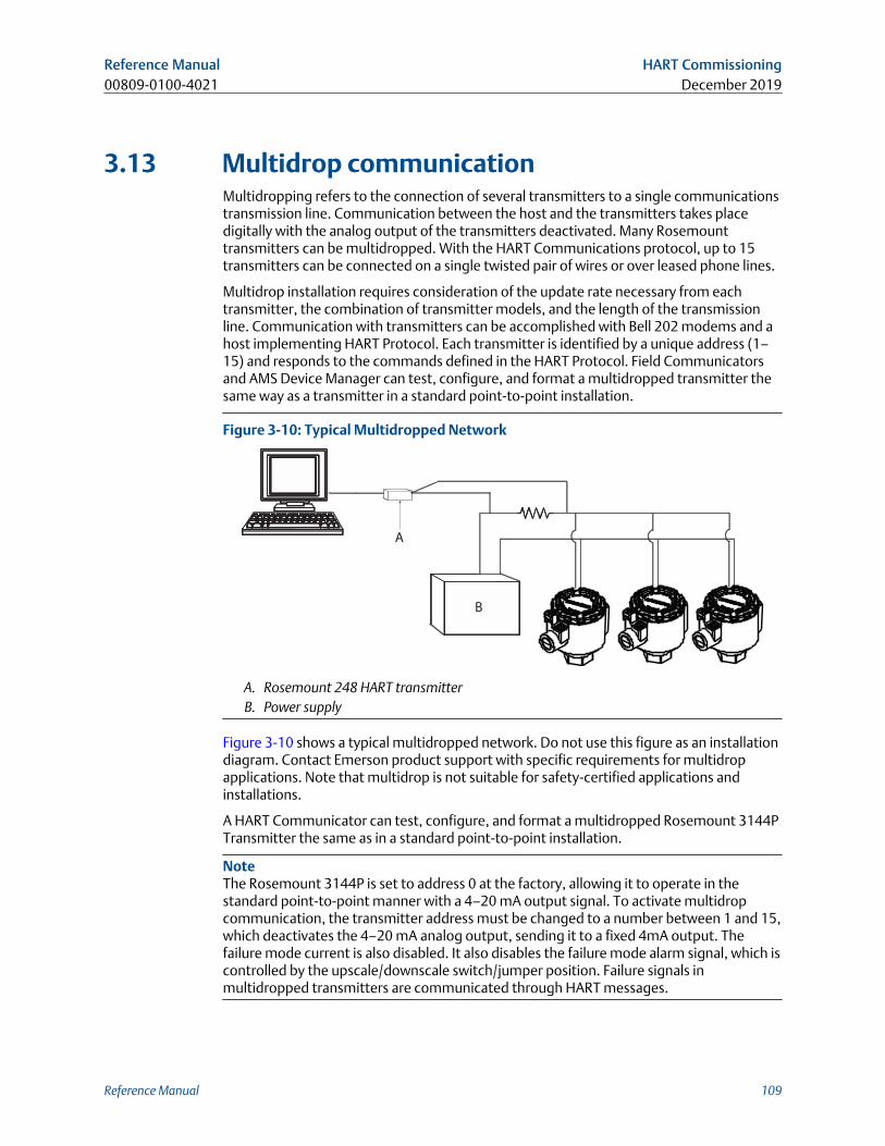
3.13 Multidrop communicationMultidropping refers to the connection of several transmitters to a single communicationstransmission line. Communication between the host and the transmitters takes placedigitally with the analog output of the transmitters deactivated. Many Rosemounttransmitters can be multidropped. With the HART Communications protocol, up to 15transmitters can be connected on a single twisted pair of wires or over leased phone lines.
Multidrop installation requires consideration of the update rate necessary from eachtransmitter, the combination of transmitter models, and the length of the transmissionline. Communication with transmitters can be accomplished with Bell 202 modems and ahost implementing HART Protocol. Each transmitter is identified by a unique address (1–15) and responds to the commands defined in the HART Protocol. Field Communicatorsand AMS Device Manager can test, configure, and format a multidropped transmitter thesame way as a transmitter in a standard point-to-point installation.
Figure 3-10: Typical Multidropped Network
A
B
A. Rosemount 248 HART transmitterB. Power supply
Figure 3-10 shows a typical multidropped network. Do not use this figure as an installationdiagram. Contact Emerson product support with specific requirements for multidropapplications. Note that multidrop is not suitable for safety-certified applications andinstallations.
A HART Communicator can test, configure, and format a multidropped Rosemount 3144PTransmitter the same as in a standard point-to-point installation.
NoteThe Rosemount 3144P is set to address 0 at the factory, allowing it to operate in thestandard point-to-point manner with a 4–20 mA output signal. To activate multidropcommunication, the transmitter address must be changed to a number between 1 and 15,which deactivates the 4–20 mA analog output, sending it to a fixed 4mA output. Thefailure mode current is also disabled. It also disables the failure mode alarm signal, which iscontrolled by the upscale/downscale switch/jumper position. Failure signals inmultidropped transmitters are communicated through HART messages.
Reference Manual HART Commissioning00809-0100-4021 December 2019
Reference Manual 109
3.14 Use with the HART Tri-LoopTo prepare the Rosemount 3144P Transmitter with dual-sensor option for use with aRosemount 333 HART Tri-Loop, the transmitter must be configured to Burst Mode and theprocess variable output order must be set. In Burst Mode, the transmitter provides digitalinformation for the four process variables to the HART Tri-Loop. The HART Tri-Loop dividesthe signal into separate 4–20 mA loops for up to three of the following choices:
• Primary Variable (PV)
• Secondary Variable (SV)
• Tertiary Variable (TV)
• Quaternary Variable (QV)
When using the Rosemount 3144P Transmitter with dual-sensor option in conjunctionwith the HART Tri-Loop, consider the configuration of the differential, average, first goodtemperatures, Sensor Drift Alert, and Hot Backup features (if applicable).
NoteThe procedures are to be used when the sensors and transmitters are connected,powered, and functioning properly. Also, Field Communicator must be connected andcommunicating to the transmitter control loop. .
3.14.1 Set the transmitter to Burst ModeHART 5 Fast Keys 2, 2, 8, 4
HART 7 Fast Keys 2, 2, 8, 4
3.14.2 Set process variable output orderHART 5 Fast Keys 2, 2, 8, 5
HART 7 Fast Keys 2, 2, 8, 5
NoteTake careful note of the process variable output order. The HART Tri-Loop must beconfigured to read the variables in the same order.
Special considerations
To initiate operation between a transmitter with dual-sensor option and the HART Tri-Loop, consider the configuration of both the differential, average and first goodtemperatures, sensor drift alert, and Hot Backup features (if applicable).
HART Commissioning Reference ManualDecember 2019 00809-0100-4021
110 Rosemount 3144P
Differential temperature measurement
To enable the differential temperature measurement feature of a dual-sensor operating inconjunction with the HART Tri-Loop, adjust the range end points of the correspondingchannel on the HART Tri-Loop to include zero. For example, if the secondary variable is toreport the differential temperature, configure the transmitter accordingly (see Set processvariable output order) and adjust the corresponding channel of the HART Tri-Loop so onerange end point is negative and the other is positive.
Hot Backup
To enable the Hot Backup feature of a transmitter with dual-sensor option operating inconjunction with the HART Tri-Loop, ensure that the output units of the sensors are thesame as the units of the HART Tri-Loop. Use any combination of RTDs or thermocouples aslong as the units of both match the units of the HART Tri-Loop.
3.14.3 Using the Tri-Loop to detect sensor drift alertThe dual-sensor transmitter sets a failure flag (through HART) whenever a sensor failureoccurs. If an analog warning is required, the HART Tri-Loop can be configured to producean analog signal that can be interpreted by the control system as a sensor failure.
Use these steps to set up the HART Tri-Loop to transmit sensor failure alerts.
Procedure
1. Configure the dual-sensor Rosemount 3144P Transmitter variable map as shown:
Variable Mapping
PV Sensor 1 or sensor average
SV Sensor 2
TV Differential temperature
QV As desired
2. Configure Channel 1 of the HART Tri-Loop as TV (differential temperature). If eithersensor should fail, the differential temperature output will be +9999 or –9999 (highor low saturation), depending on the position of the Failure Mode Switch (see Alarmswitch (HART Protocol)).
3. Select temperature units for Channel 1 that match the differential temperatureunits of the transmitter.
4. Specify a range for the TV such as –100 to 100 °C. If the range is large, then a sensordrift of a few degrees will represent only a small percent of range. If Sensor 1 orSensor 2 fails, the TV will be +9999 (high saturation) or –9999 (low saturation). Inthis example, zero is the midpoint of the TV range. If a ΔT of zero is set as the lowerrange limit (4 mA), then the output could saturate low if the reading from Sensor 2exceeds the reading from Sensor 1. By placing a zero in the middle of the range, theoutput will normally stay near 12 mA, and the problem will be avoided.
5. Configure the DCS so that TV < –100 °C or TV > 100 °C indicates a sensor failure and,for example, TV ≤ –3 °C or TV ≥ 3 °C indicates a drift alert. See Figure 3-11.
Reference Manual HART Commissioning00809-0100-4021 December 2019
Reference Manual 111
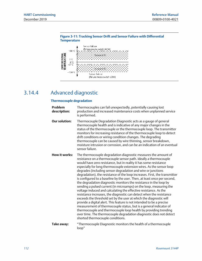
Figure 3-11: Tracking Sensor Drift and Sensor Failure with DifferentialTemperature
3.14.4 Advanced diagnosticThermocouple degradation
Problemdescription:
Thermocouples can fail unexpectedly, potentially causing lostproduction and increased maintenance costs when unplanned serviceis performed.
Our solution: Thermocouple Degradation Diagnostic acts as a gauge of generalthermocouple health and is indicative of any major changes in thestatus of the thermocouple or the thermocouple loop. The transmittermonitors for increasing resistance of the thermocouple loop to detectdrift conditions or wiring condition changes. The degradingthermocouple can be caused by wire thinning, sensor breakdown,moisture intrusion or corrosion, and can be an indication of an eventualsensor failure.
How it works: The thermocouple degradation diagnostic measures the amount ofresistance on a thermocouple sensor path. Ideally a thermocouplewould have zero resistance, but in reality it has some resistanceespecially for long thermocouple extension wires. As the sensor loopdegrades (including sensor degradation and wire or junctionsdegradation), the resistance of the loop increases. First, the transmitteris configured to a baseline by the user. Then, at least once per second,the degradation diagnostic monitors the resistance in the loop bysending a pulsed current (in microamps) on the loop, measuring thevoltage induced and calculating the effective resistance. As theresistance increases, the diagnostic can detect when the resistanceexceeds the threshold set by the user at which the diagnostic willprovide a digital alert. This feature is not intended to be a precisemeasurement of thermocouple status, but is a general indicator ofthermocouple and thermocouple loop health by providing trendingover time. The thermocouple degradation diagnostic does not detectshorted thermocouple conditions.
Take away: “Thermocouple Diagnostic monitors the health of a thermocoupleloop”
HART Commissioning Reference ManualDecember 2019 00809-0100-4021
112 Rosemount 3144P
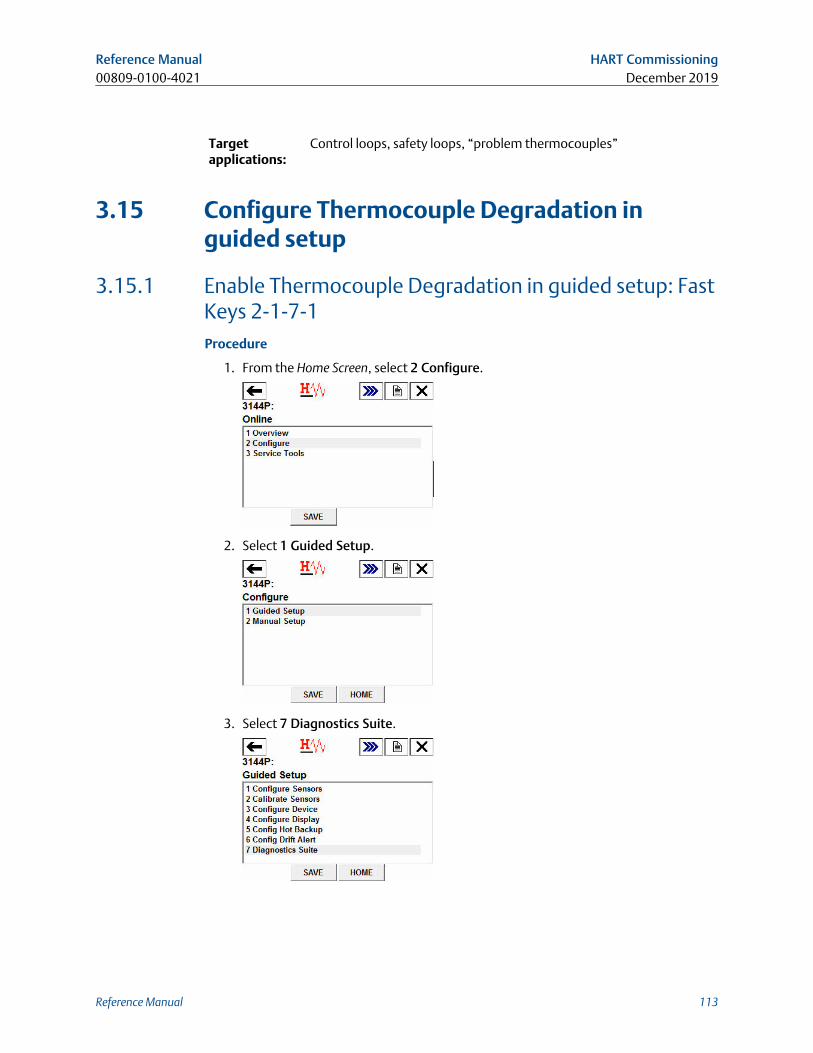
Targetapplications:
Control loops, safety loops, “problem thermocouples”
3.15 Configure Thermocouple Degradation inguided setup
3.15.1 Enable Thermocouple Degradation in guided setup: FastKeys 2-1-7-1Procedure
1. From the Home Screen, select 2 Configure.
2. Select 1 Guided Setup.
3. Select 7 Diagnostics Suite.
Reference Manual HART Commissioning00809-0100-4021 December 2019
Reference Manual 113
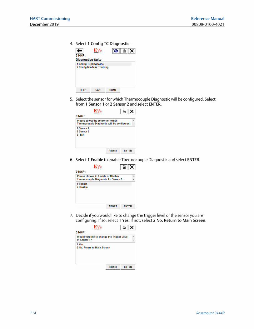
4. Select 1 Config TC Diagnostic.
5. Select the sensor for which Thermocouple Diagnostic will be configured. Selectfrom 1 Sensor 1 or 2 Sensor 2 and select ENTER.
6. Select 1 Enable to enable Thermocouple Diagnostic and select ENTER.
7. Decide if you would like to change the trigger level or the sensor you areconfiguring. If so, select 1 Yes. If not, select 2 No. Return to Main Screen.
HART Commissioning Reference ManualDecember 2019 00809-0100-4021
114 Rosemount 3144P
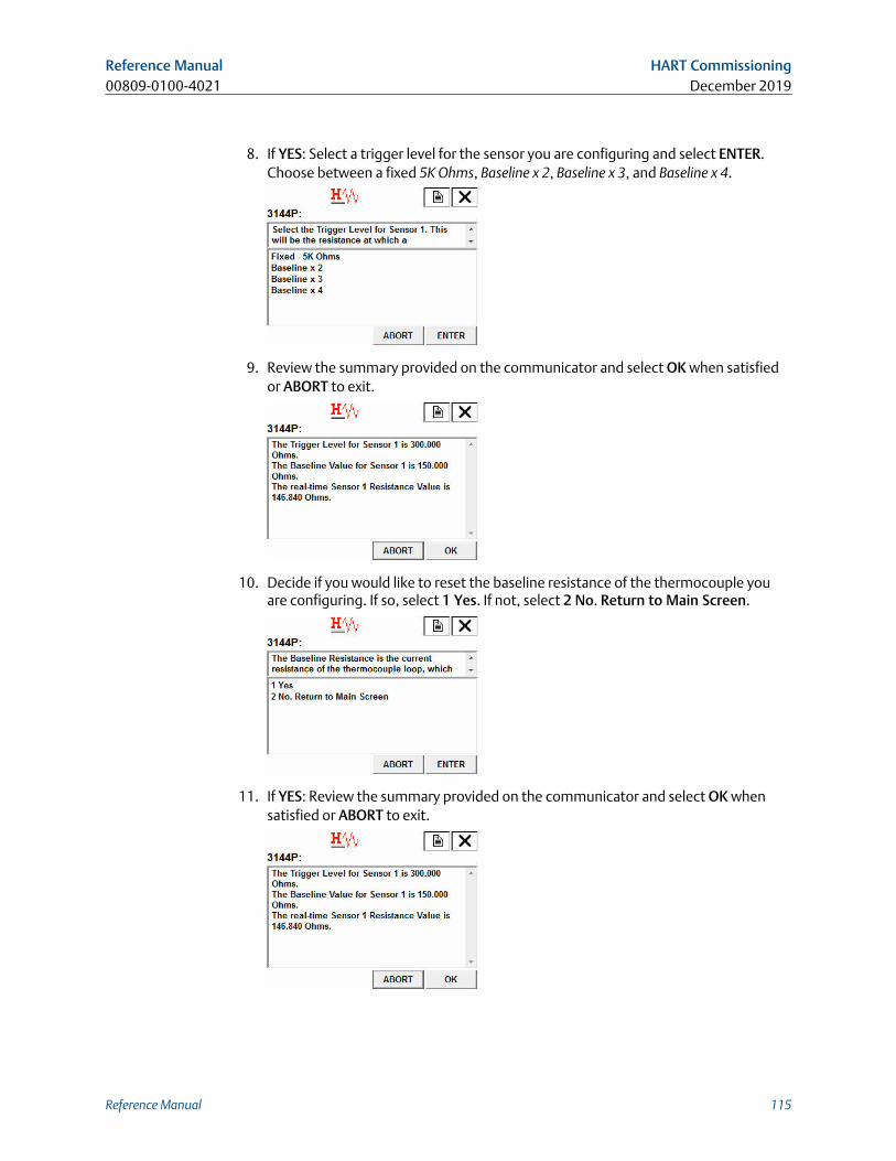
8. If YES: Select a trigger level for the sensor you are configuring and select ENTER.Choose between a fixed 5K Ohms, Baseline x 2, Baseline x 3, and Baseline x 4.
9. Review the summary provided on the communicator and select OK when satisfiedor ABORT to exit.
10. Decide if you would like to reset the baseline resistance of the thermocouple youare configuring. If so, select 1 Yes. If not, select 2 No. Return to Main Screen.
11. If YES: Review the summary provided on the communicator and select OK whensatisfied or ABORT to exit.
Reference Manual HART Commissioning00809-0100-4021 December 2019
Reference Manual 115
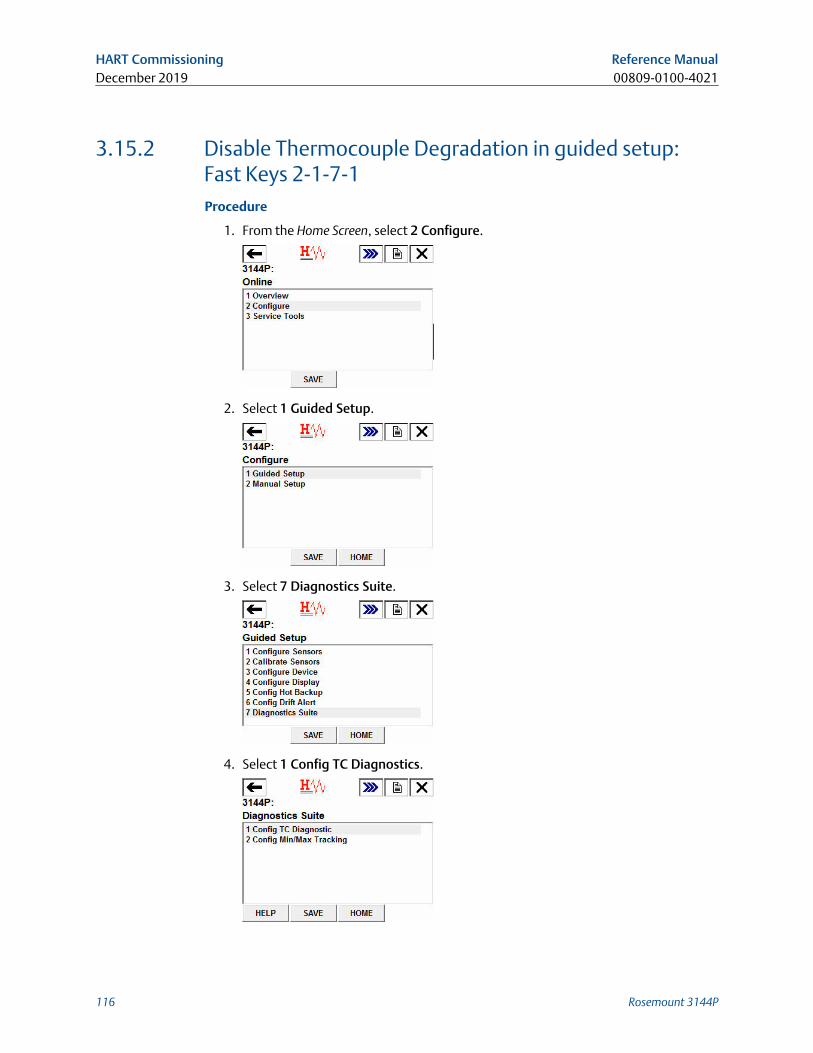
3.15.2 Disable Thermocouple Degradation in guided setup:Fast Keys 2-1-7-1Procedure
1. From the Home Screen, select 2 Configure.
2. Select 1 Guided Setup.
3. Select 7 Diagnostics Suite.
4. Select 1 Config TC Diagnostics.
HART Commissioning Reference ManualDecember 2019 00809-0100-4021
116 Rosemount 3144P
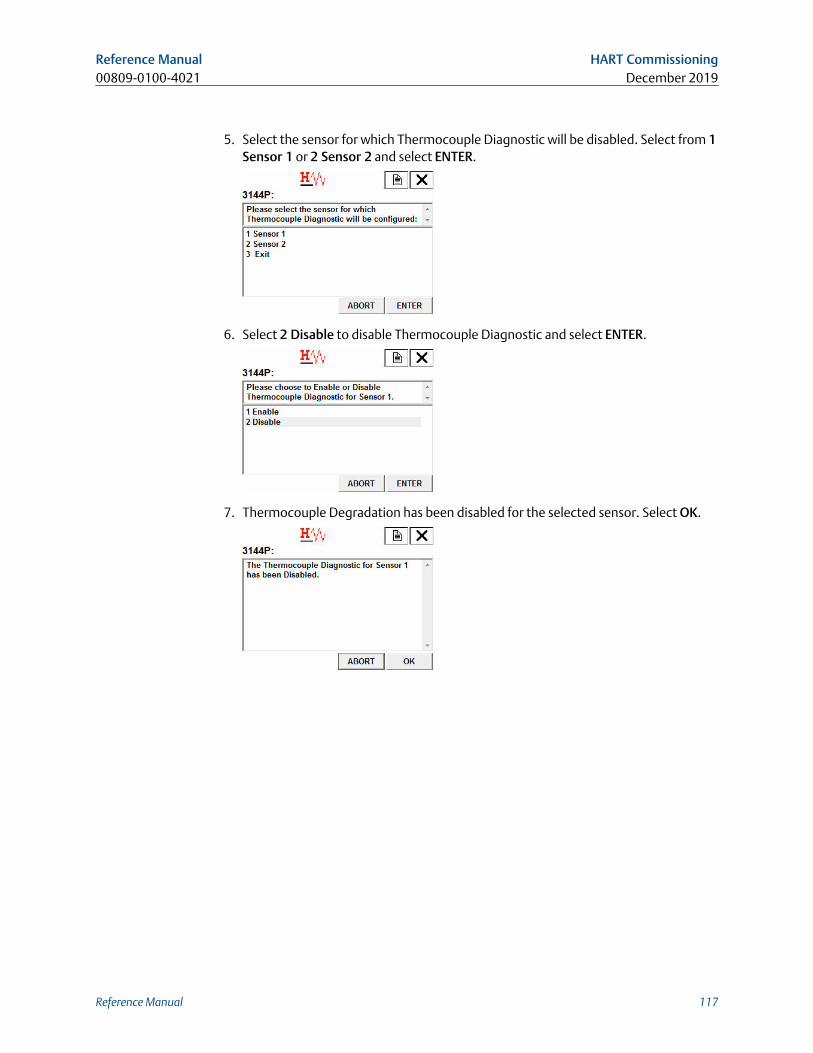
5. Select the sensor for which Thermocouple Diagnostic will be disabled. Select from 1Sensor 1 or 2 Sensor 2 and select ENTER.
6. Select 2 Disable to disable Thermocouple Diagnostic and select ENTER.
7. Thermocouple Degradation has been disabled for the selected sensor. Select OK.
Reference Manual HART Commissioning00809-0100-4021 December 2019
Reference Manual 117
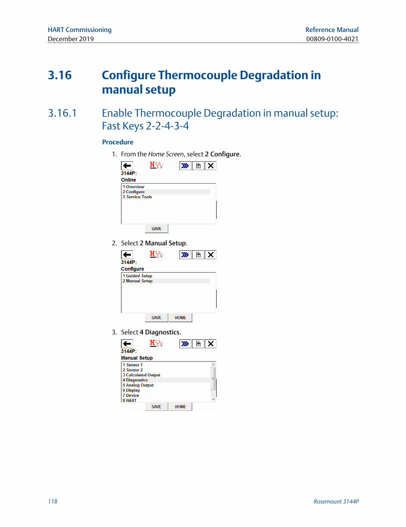
3.16 Configure Thermocouple Degradation inmanual setup
3.16.1 Enable Thermocouple Degradation in manual setup:Fast Keys 2-2-4-3-4Procedure
1. From the Home Screen, select 2 Configure.
2. Select 2 Manual Setup.
3. Select 4 Diagnostics.
HART Commissioning Reference ManualDecember 2019 00809-0100-4021
118 Rosemount 3144P
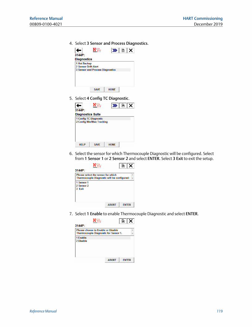
4. Select 3 Sensor and Process Diagnostics.
5. Select 4 Config TC Diagnostic.
6. Select the sensor for which Thermocouple Diagnostic will be configured. Selectfrom 1 Sensor 1 or 2 Sensor 2 and select ENTER. Select 3 Exit to exit the setup.
7. Select 1 Enable to enable Thermocouple Diagnostic and select ENTER.
Reference Manual HART Commissioning00809-0100-4021 December 2019
Reference Manual 119
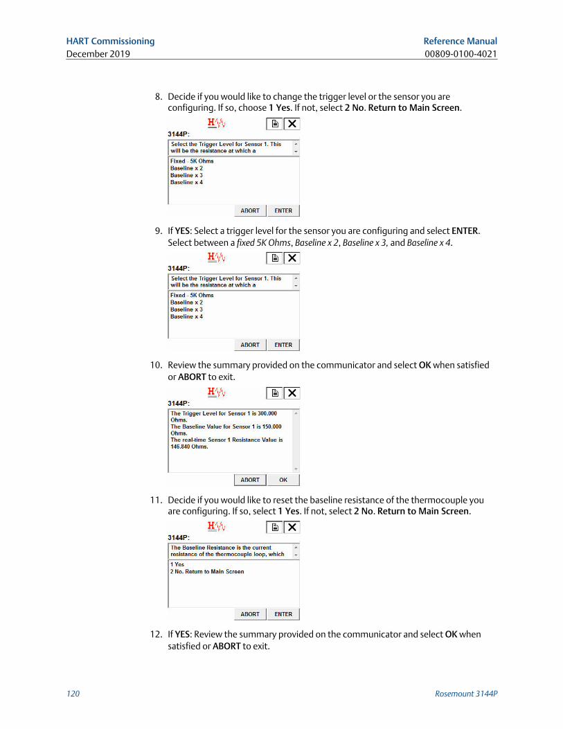
8. Decide if you would like to change the trigger level or the sensor you areconfiguring. If so, choose 1 Yes. If not, select 2 No. Return to Main Screen.
9. If YES: Select a trigger level for the sensor you are configuring and select ENTER.Select between a fixed 5K Ohms, Baseline x 2, Baseline x 3, and Baseline x 4.
10. Review the summary provided on the communicator and select OK when satisfiedor ABORT to exit.
11. Decide if you would like to reset the baseline resistance of the thermocouple youare configuring. If so, select 1 Yes. If not, select 2 No. Return to Main Screen.
12. If YES: Review the summary provided on the communicator and select OK whensatisfied or ABORT to exit.
HART Commissioning Reference ManualDecember 2019 00809-0100-4021
120 Rosemount 3144P
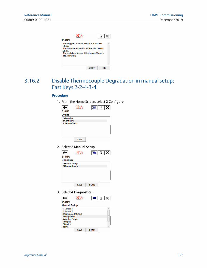
3.16.2 Disable Thermocouple Degradation in manual setup:Fast Keys 2-2-4-3-4Procedure
1. From the Home Screen, select 2 Configure.
2. Select 2 Manual Setup.
3. Select 4 Diagnostics.
Reference Manual HART Commissioning00809-0100-4021 December 2019
Reference Manual 121
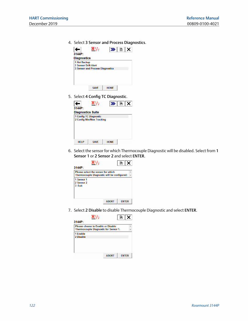
4. Select 3 Sensor and Process Diagnostics.
5. Select 4 Config TC Diagnostic.
6. Select the sensor for which Thermocouple Diagnostic will be disabled. Select from 1Sensor 1 or 2 Sensor 2 and select ENTER.
7. Select 2 Disable to disable Thermocouple Diagnostic and select ENTER.
HART Commissioning Reference ManualDecember 2019 00809-0100-4021
122 Rosemount 3144P
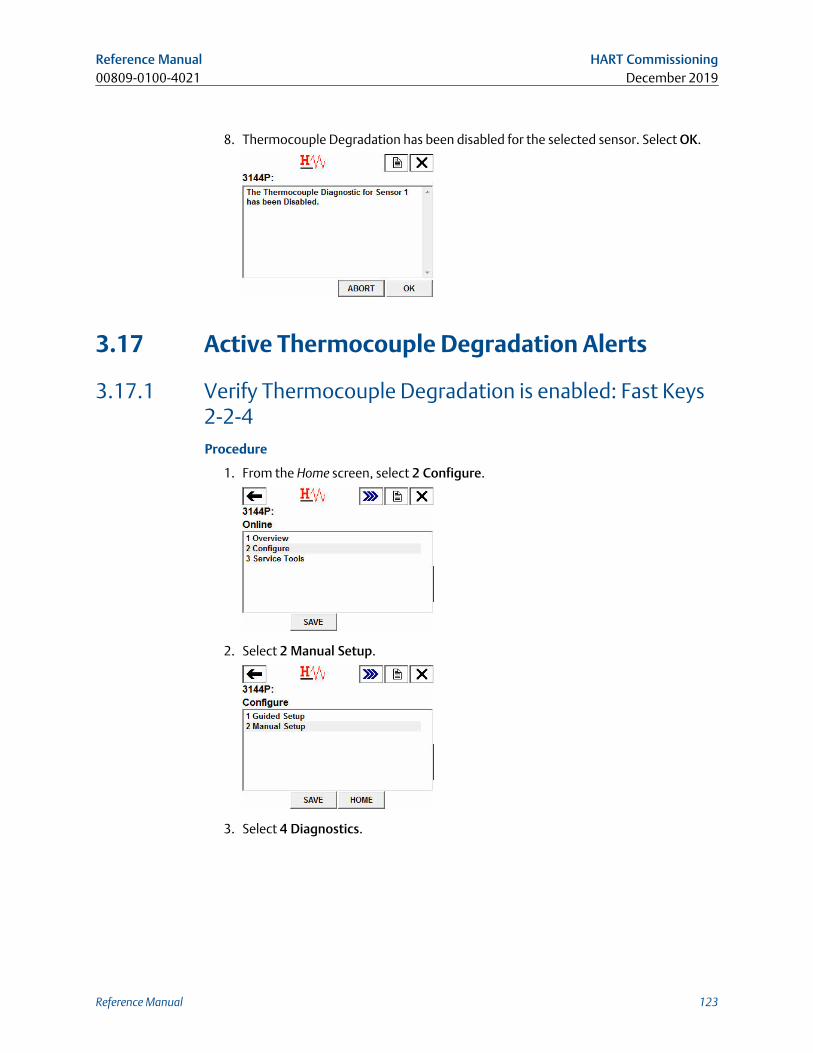
8. Thermocouple Degradation has been disabled for the selected sensor. Select OK.
3.17 Active Thermocouple Degradation Alerts
3.17.1 Verify Thermocouple Degradation is enabled: Fast Keys2-2-4Procedure
1. From the Home screen, select 2 Configure.
2. Select 2 Manual Setup.
3. Select 4 Diagnostics.
Reference Manual HART Commissioning00809-0100-4021 December 2019
Reference Manual 123
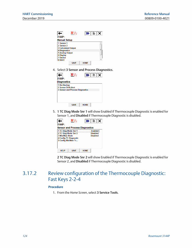
4. Select 3 Sensor and Process Diagnostics.
5. 1 TC Diag Mode Snr 1 will show Enabled if Thermocouple Diagnostic is enabled forSensor 1, and Disabled if Thermocouple Diagnostic is disabled.
2 TC Diag Mode Snr 2 will show Enabled if Thermocouple Diagnostic is enabled forSensor 2, and Disabled if Thermocouple Diagnostic is disabled.
3.17.2 Review configuration of the Thermocouple Diagnostic:Fast Keys 2-2-4Procedure
1. From the Home Screen, select 3 Service Tools.
HART Commissioning Reference ManualDecember 2019 00809-0100-4021
124 Rosemount 3144P
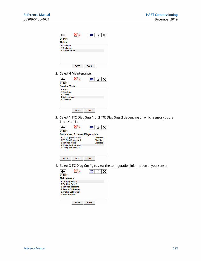
2. Select 4 Maintenance.
3. Select 1 T/C Diag Snsr 1 or 2 T/C Diag Snsr 2 depending on which sensor you areinterested in.
4. Select 3 TC Diag Config to view the configuration information of your sensor.
Reference Manual HART Commissioning00809-0100-4021 December 2019
Reference Manual 125
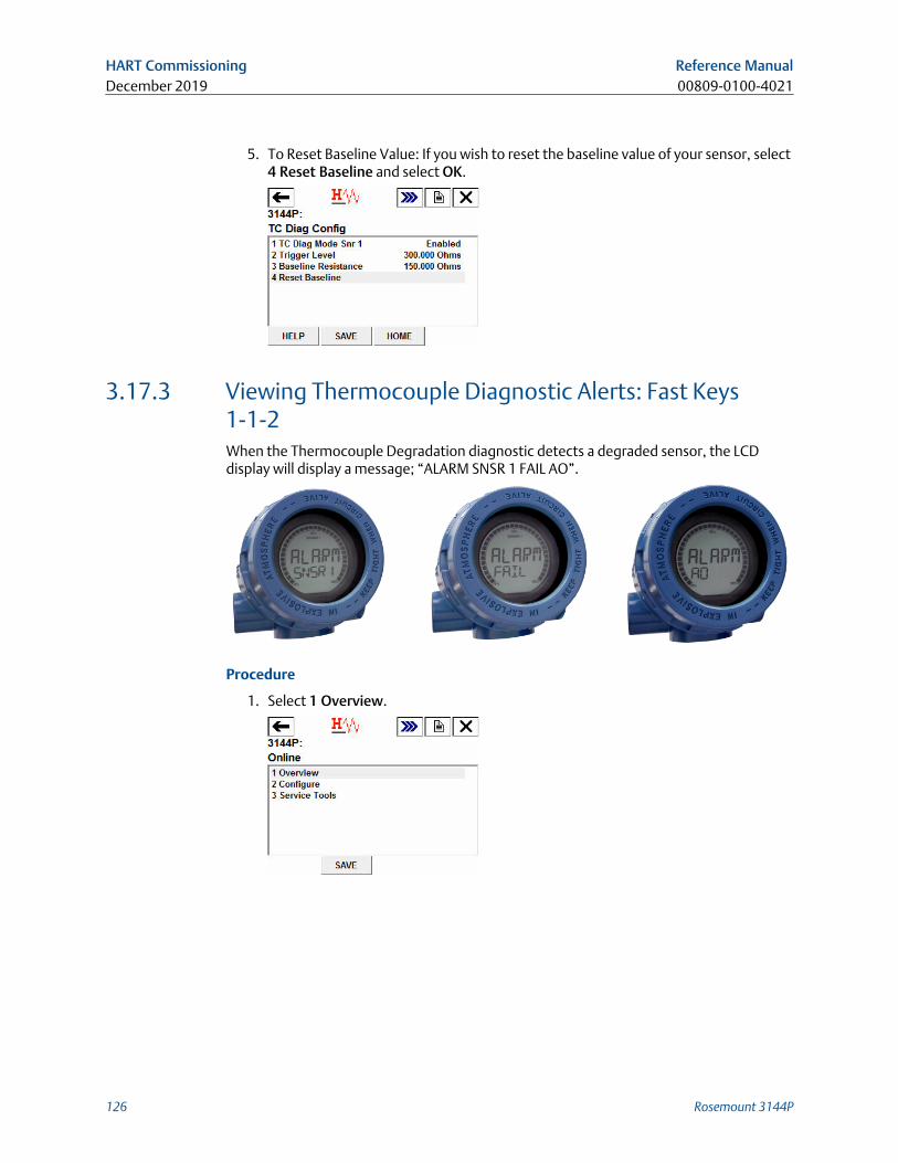
5. To Reset Baseline Value: If you wish to reset the baseline value of your sensor, select4 Reset Baseline and select OK.
3.17.3 Viewing Thermocouple Diagnostic Alerts: Fast Keys1-1-2When the Thermocouple Degradation diagnostic detects a degraded sensor, the LCDdisplay will display a message; “ALARM SNSR 1 FAIL AO”.
Procedure
1. Select 1 Overview.
HART Commissioning Reference ManualDecember 2019 00809-0100-4021
126 Rosemount 3144P
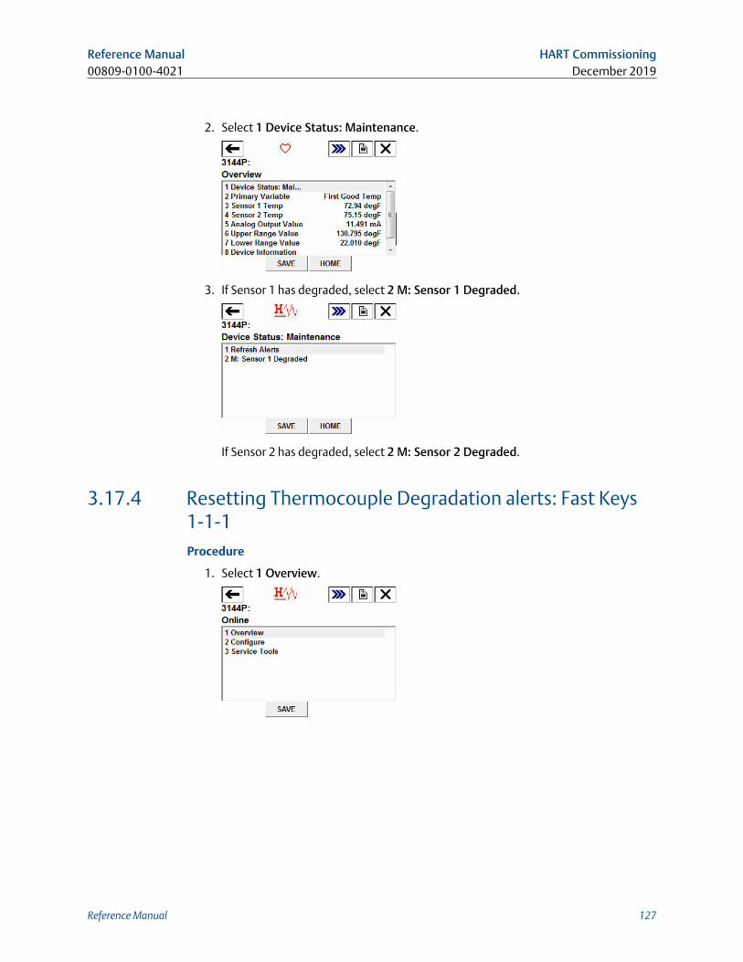
2. Select 1 Device Status: Maintenance.
3. If Sensor 1 has degraded, select 2 M: Sensor 1 Degraded.
If Sensor 2 has degraded, select 2 M: Sensor 2 Degraded.
3.17.4 Resetting Thermocouple Degradation alerts: Fast Keys1-1-1Procedure
1. Select 1 Overview.
Reference Manual HART Commissioning00809-0100-4021 December 2019
Reference Manual 127
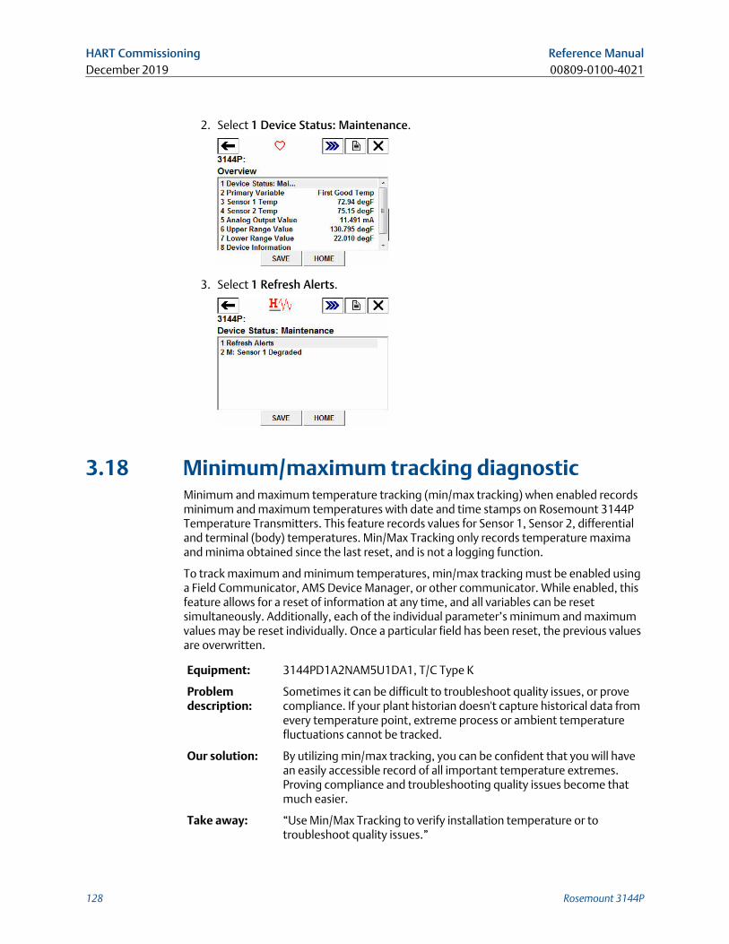
2. Select 1 Device Status: Maintenance.
3. Select 1 Refresh Alerts.
3.18 Minimum/maximum tracking diagnosticMinimum and maximum temperature tracking (min/max tracking) when enabled recordsminimum and maximum temperatures with date and time stamps on Rosemount 3144PTemperature Transmitters. This feature records values for Sensor 1, Sensor 2, differentialand terminal (body) temperatures. Min/Max Tracking only records temperature maximaand minima obtained since the last reset, and is not a logging function.
To track maximum and minimum temperatures, min/max tracking must be enabled usinga Field Communicator, AMS Device Manager, or other communicator. While enabled, thisfeature allows for a reset of information at any time, and all variables can be resetsimultaneously. Additionally, each of the individual parameter’s minimum and maximumvalues may be reset individually. Once a particular field has been reset, the previous valuesare overwritten.
Equipment: 3144PD1A2NAM5U1DA1, T/C Type K
Problemdescription:
Sometimes it can be difficult to troubleshoot quality issues, or provecompliance. If your plant historian doesn't capture historical data fromevery temperature point, extreme process or ambient temperaturefluctuations cannot be tracked.
Our solution: By utilizing min/max tracking, you can be confident that you will havean easily accessible record of all important temperature extremes.Proving compliance and troubleshooting quality issues become thatmuch easier.
Take away: “Use Min/Max Tracking to verify installation temperature or totroubleshoot quality issues.”
HART Commissioning Reference ManualDecember 2019 00809-0100-4021
128 Rosemount 3144P
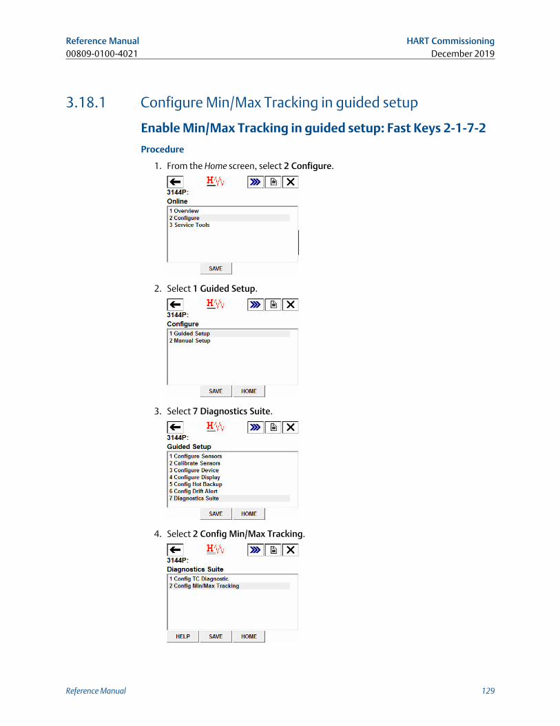
3.18.1 Configure Min/Max Tracking in guided setup
Enable Min/Max Tracking in guided setup: Fast Keys 2-1-7-2
Procedure
1. From the Home screen, select 2 Configure.
2. Select 1 Guided Setup.
3. Select 7 Diagnostics Suite.
4. Select 2 Config Min/Max Tracking.
Reference Manual HART Commissioning00809-0100-4021 December 2019
Reference Manual 129
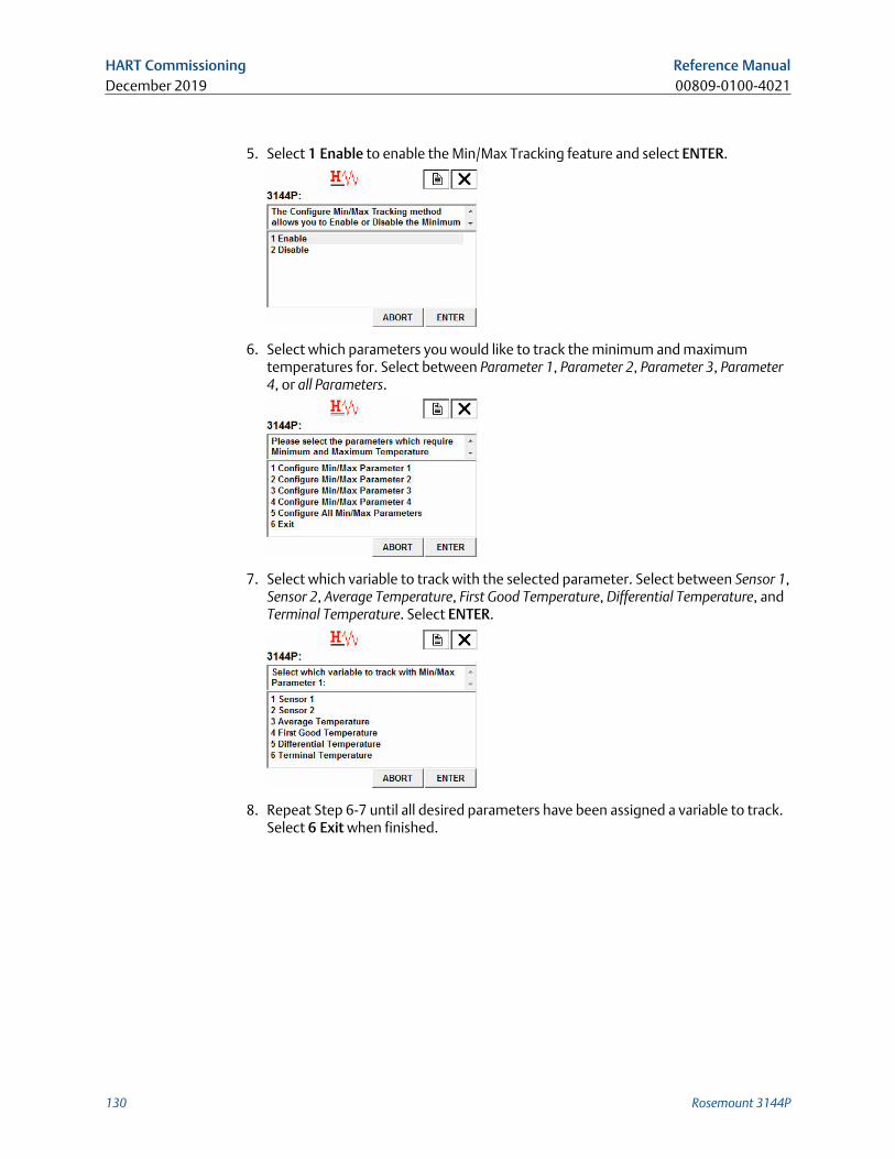
5. Select 1 Enable to enable the Min/Max Tracking feature and select ENTER.
6. Select which parameters you would like to track the minimum and maximumtemperatures for. Select between Parameter 1, Parameter 2, Parameter 3, Parameter4, or all Parameters.
7. Select which variable to track with the selected parameter. Select between Sensor 1,Sensor 2, Average Temperature, First Good Temperature, Differential Temperature, andTerminal Temperature. Select ENTER.
8. Repeat Step 6-7 until all desired parameters have been assigned a variable to track.Select 6 Exit when finished.
HART Commissioning Reference ManualDecember 2019 00809-0100-4021
130 Rosemount 3144P
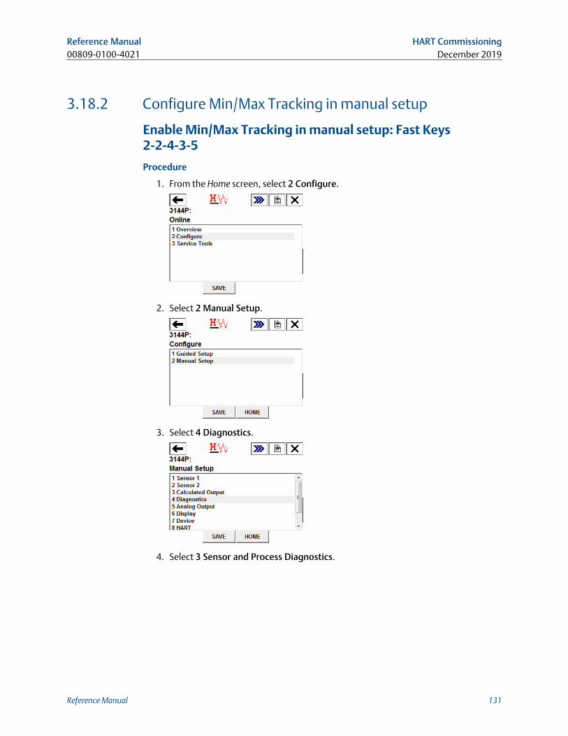
3.18.2 Configure Min/Max Tracking in manual setup
Enable Min/Max Tracking in manual setup: Fast Keys2-2-4-3-5
Procedure
1. From the Home screen, select 2 Configure.
2. Select 2 Manual Setup.
3. Select 4 Diagnostics.
4. Select 3 Sensor and Process Diagnostics.
Reference Manual HART Commissioning00809-0100-4021 December 2019
Reference Manual 131
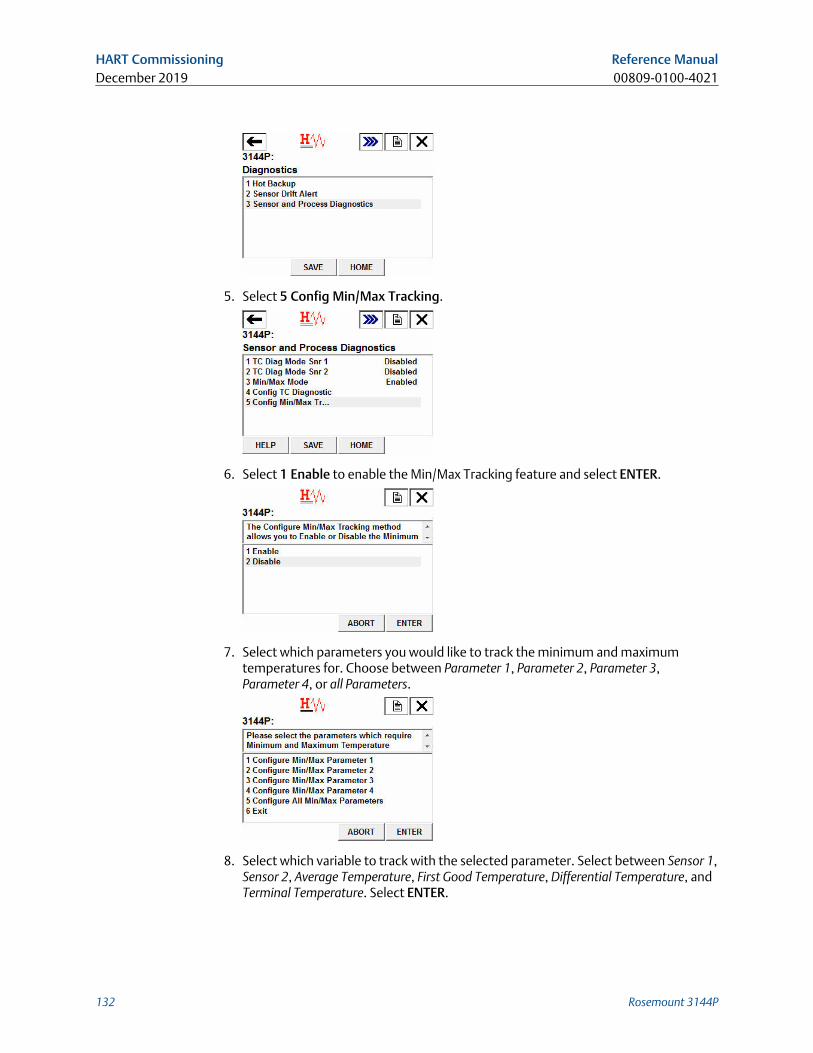
5. Select 5 Config Min/Max Tracking.
6. Select 1 Enable to enable the Min/Max Tracking feature and select ENTER.
7. Select which parameters you would like to track the minimum and maximumtemperatures for. Choose between Parameter 1, Parameter 2, Parameter 3,Parameter 4, or all Parameters.
8. Select which variable to track with the selected parameter. Select between Sensor 1,Sensor 2, Average Temperature, First Good Temperature, Differential Temperature, andTerminal Temperature. Select ENTER.
HART Commissioning Reference ManualDecember 2019 00809-0100-4021
132 Rosemount 3144P
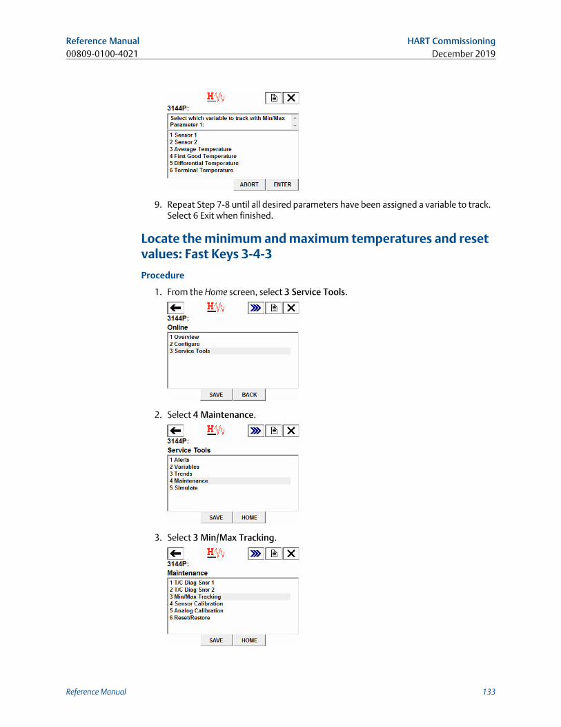
9. Repeat Step 7-8 until all desired parameters have been assigned a variable to track.Select 6 Exit when finished.
Locate the minimum and maximum temperatures and resetvalues: Fast Keys 3-4-3
Procedure
1. From the Home screen, select 3 Service Tools.
2. Select 4 Maintenance.
3. Select 3 Min/Max Tracking.
Reference Manual HART Commissioning00809-0100-4021 December 2019
Reference Manual 133
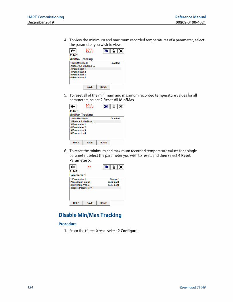
4. To view the minimum and maximum recorded temperatures of a parameter, selectthe parameter you wish to view.
5. To reset all of the minimum and maximum recorded temperature values for allparameters, select 2 Reset All Min/Max.
6. To reset the minimum and maximum recorded temperature values for a singleparameter, select the parameter you wish to reset, and then select 4 ResetParameter X.
Disable Min/Max Tracking
Procedure
1. From the Home Screen, select 2 Configure.
HART Commissioning Reference ManualDecember 2019 00809-0100-4021
134 Rosemount 3144P
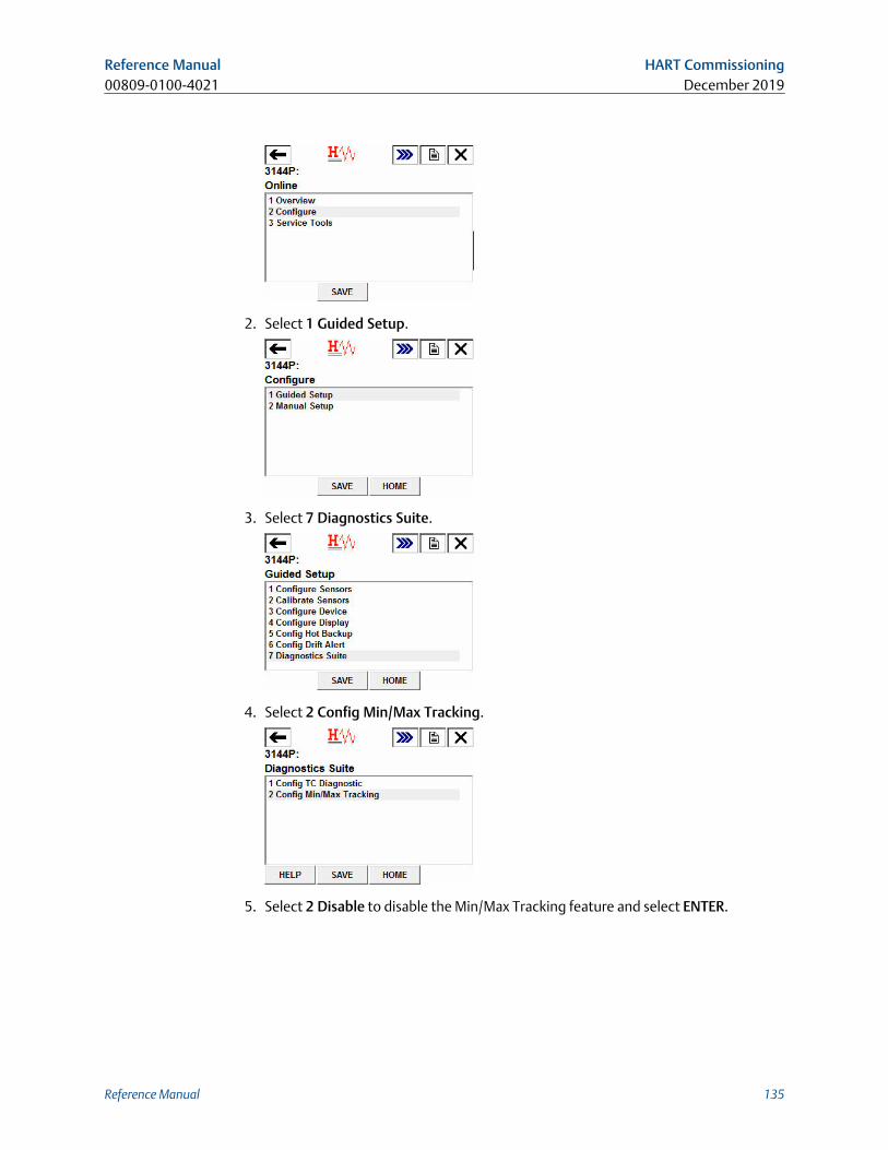
2. Select 1 Guided Setup.
3. Select 7 Diagnostics Suite.
4. Select 2 Config Min/Max Tracking.
5. Select 2 Disable to disable the Min/Max Tracking feature and select ENTER.
Reference Manual HART Commissioning00809-0100-4021 December 2019
Reference Manual 135
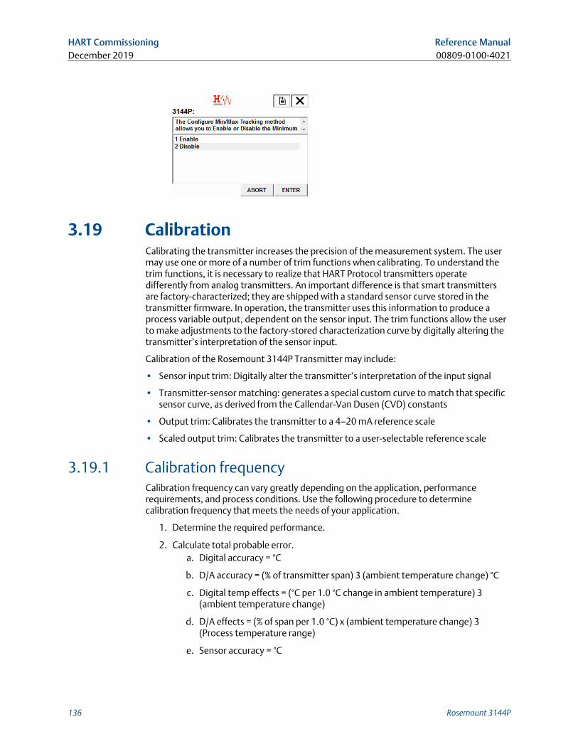
3.19 CalibrationCalibrating the transmitter increases the precision of the measurement system. The usermay use one or more of a number of trim functions when calibrating. To understand thetrim functions, it is necessary to realize that HART Protocol transmitters operatedifferently from analog transmitters. An important difference is that smart transmittersare factory-characterized; they are shipped with a standard sensor curve stored in thetransmitter firmware. In operation, the transmitter uses this information to produce aprocess variable output, dependent on the sensor input. The trim functions allow the userto make adjustments to the factory-stored characterization curve by digitally altering thetransmitter’s interpretation of the sensor input.
Calibration of the Rosemount 3144P Transmitter may include:
• Sensor input trim: Digitally alter the transmitter’s interpretation of the input signal
• Transmitter-sensor matching: generates a special custom curve to match that specificsensor curve, as derived from the Callendar-Van Dusen (CVD) constants
• Output trim: Calibrates the transmitter to a 4–20 mA reference scale
• Scaled output trim: Calibrates the transmitter to a user-selectable reference scale
3.19.1 Calibration frequencyCalibration frequency can vary greatly depending on the application, performancerequirements, and process conditions. Use the following procedure to determinecalibration frequency that meets the needs of your application.
1. Determine the required performance.
2. Calculate total probable error.a. Digital accuracy = °C
b. D/A accuracy = (% of transmitter span) 3 (ambient temperature change) °C
c. Digital temp effects = (°C per 1.0 °C change in ambient temperature) 3(ambient temperature change)
d. D/A effects = (% of span per 1.0 °C) x (ambient temperature change) 3(Process temperature range)
e. Sensor accuracy = °C
HART Commissioning Reference ManualDecember 2019 00809-0100-4021
136 Rosemount 3144P
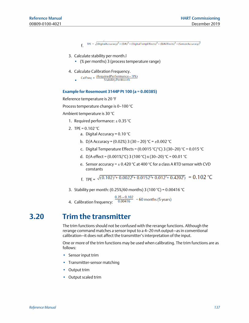
f.
3. Calculate stability per month.l• (% per months) 3 (process temperature range)
4. Calculate Calibration Frequency.
•
Example for Rosemount 3144P Pt 100 (a = 0.00385)
Reference temperature is 20 °F
Process temperature change is 0–100 °C
Ambient temperature is 30 °C
1. Required performance: ± 0.35 °C
2. TPE = 0.102 °Ca. Digital Accuracy = 0.10 °C
b. D/A Accuracy = (0.02%) 3 (30 – 20) °C = ±0.002 °C
c. Digital Temperature Effects = (0.0015 °C/°C) 3 (30–20) °C = 0.015 °C
d. D/A effect = (0.001%/°C) 3 (100 °C) x (30–20) °C = 00.01 °C
e. Sensor accuracy = ± 0.420 °C at 400 °C for a class A RTD sensor with CVDconstants
f. TPE =
3. Stability per month: (0.25%/60 months) 3 (100 °C) = 0.00416 °C
4. Calibration frequency:
3.20 Trim the transmitterThe trim functions should not be confused with the rerange functions. Although thererange command matches a sensor input to a 4–20 mA output—as in conventionalcalibration—it does not affect the transmitter’s interpretation of the input.
One or more of the trim functions may be used when calibrating. The trim functions are asfollows:
• Sensor input trim
• Transmitter-sensor matching
• Output trim
• Output scaled trim
Reference Manual HART Commissioning00809-0100-4021 December 2019
Reference Manual 137
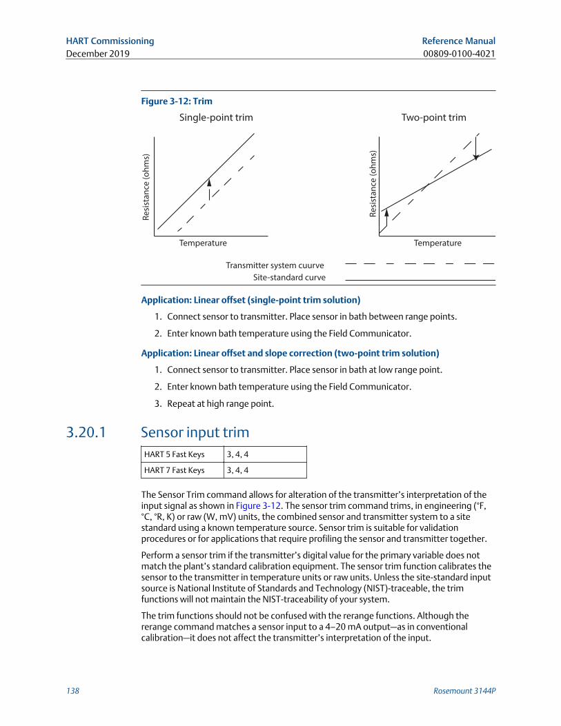
Figure 3-12: Trim
Transmitter system cuurve
Site-standard curve
Re
sist
an
ce (
oh
ms)
Re
sist
an
ce (
oh
ms)
Temperature Temperature
Single-point trim Two-point trim
Application: Linear offset (single-point trim solution)
1. Connect sensor to transmitter. Place sensor in bath between range points.
2. Enter known bath temperature using the Field Communicator.
Application: Linear offset and slope correction (two-point trim solution)
1. Connect sensor to transmitter. Place sensor in bath at low range point.
2. Enter known bath temperature using the Field Communicator.
3. Repeat at high range point.
3.20.1 Sensor input trimHART 5 Fast Keys 3, 4, 4
HART 7 Fast Keys 3, 4, 4
The Sensor Trim command allows for alteration of the transmitter’s interpretation of theinput signal as shown in Figure 3-12. The sensor trim command trims, in engineering (°F,°C, °R, K) or raw (W, mV) units, the combined sensor and transmitter system to a sitestandard using a known temperature source. Sensor trim is suitable for validationprocedures or for applications that require profiling the sensor and transmitter together.
Perform a sensor trim if the transmitter’s digital value for the primary variable does notmatch the plant’s standard calibration equipment. The sensor trim function calibrates thesensor to the transmitter in temperature units or raw units. Unless the site-standard inputsource is National Institute of Standards and Technology (NIST)-traceable, the trimfunctions will not maintain the NIST-traceability of your system.
The trim functions should not be confused with the rerange functions. Although thererange command matches a sensor input to a 4–20 mA output—as in conventionalcalibration—it does not affect the transmitter’s interpretation of the input.
HART Commissioning Reference ManualDecember 2019 00809-0100-4021
138 Rosemount 3144P
NoteA warning will appear Setting the loop to manual.
3.20.2 Active calibrator and Electric and Magnetic Field (EMF)compensation
HART 5 Fast Keys 3, 4, 4, 4
HART 7 Fast Keys 3, 4, 4, 4
The transmitter operates with a pulsating sensor current to allow EMF compensation anddetection of open sensor conditions. Because some calibration equipment requires asteady sensor current to function properly, the “Active Calibrator Mode” feature should beused when an active calibrator is connected. Enabling this mode temporarily sets thetransmitter to provide steady sensor current unless two sensor inputs are configured.Disable this mode before putting the transmitter back into the process to set thetransmitter back to pulsating current. “Active Calibrator Mode” is volatile and willautomatically be disabled when a master reset is performed (through HART Protocol) orwhen the power is cycled.
EMF compensation allows the transmitter to provide sensor measurements that areunaffected by unwanted voltages, typically due to thermal EMFs in the equipmentconnected to the transmitter, or by some types of calibration equipment. If thisequipment also requires steady sensor current, the transmitter must be set to “ActiveCalibrator Mode.” However, the steady current does not allow the transmitter to performEMF compensation and as a result, a difference in readings between the active calibratorand actual sensor may exist.
If a reading difference is experienced and is greater than the plant’s accuracy specificationallows, perform a sensor trim with “Active Calibrator Mode” disabled. In this case, anactive calibrator capable of tolerating pulsating sensor current must be used or the actualsensors must be connected to the transmitter. When the field communicator or AMSDevice Manager asks if an Active Calibrator is being used when the sensor trim routine isentered, select No to leave the “Active Calibrator Mode” disabled.
In temperature measurement loops using RTDs, small voltages, called EMFs, can beinduced on the sensor wires, increasing the effective resistance and causing falsetemperature readings. For example, a 12 mV reading equates to 390 °F or 60 W error for aPT100 385 RTD.
The Emerson EMF Compensation detects these externally induced voltages and eliminatesthe erroneous voltages from the calculations performed by the transmitters. Externallyinduced voltages come from motors, calibration devices (dry block calibrator), etc.
How itworks:
Our transmitter provides RTD measurement updates at a rate of less than onesecond for a single sensor. This measurement update consists of a series ofsmaller measurement scans. A part of these smaller measurement scans is acheck for EMF induced voltage, up to 12 mV, on the sensor loop. Thetransmitter is designed to compensate out the induced voltage up to 12 mVand provide a corrected temperature value. Beyond 12 mV, the transmitterwill notify the user that “Excess EMF” is present and warn them of possibleinaccuracies in the temperature measurement due to excessive induced
Reference Manual HART Commissioning00809-0100-4021 December 2019
Reference Manual 139
voltage on the RTD sensor loop. In the case of excessive EMF in the transmitter,it is recommended that the user identify the external sources ofelectromagnetic interference and isolate them from the transmitter and RTDsensor wiring.
3.20.3 Transmitter-sensor matchingHART 5 Fast Keys Sensor 1 - 2, 2, 1, 11
HART 7 Fast Keys Sensor 1 - 2, 2, 1, 11
The transmitter accepts CVD constants from a calibrated RTD schedule and generates aspecial custom curve to match that specific sensor Resistance vs. Temperatureperformance. Matching the specific sensor curve with the transmitter significantlyenhances the temperature measurement accuracy. See the comparison below:
System Accuracy Comparison at 150 °C Using a PT 100 (a=0.00385) RTD with a Span of 0 to200 °C
Standard RTD Matched RTD
Rosemount 3144P ±0.08 °C Rosemount 3144P ±0.08 °C
Standard RTD ±1.05 °C Matched RTD ±0.18 °C
Total System(1) ±1.05 °C Total System(1) ±0.21 °C
(1) Calculated using root-summed-squared (RSS) statistical method.
Problemdescription:
Depending on the process being measured, a certain amount ofaccuracy may be needed from the sensor.
Our solution: A more precise compensation for RTD inaccuracies is provided byTransmitter-Sensor Matching using the transmitter's factoryprogrammed CVD equation. This equation describes the relationshipbetween resistance and temperature of platinum resistancethermometers (RTDs). The matching process allows the user to enterthe four sensor specific CVD constants into the transmitter. Thetransmitter uses these sensor-specific constants in solving the CVDequation to match the transmitter to that specific sensor thusproviding outstanding accuracy.
Take away: “Transmitter-Sensor Matching customizes sensor curves to minimizesensor inaccuracy”
NoteIn order to use this diagnostic, the RTD must be set as type Cal VanDusen.
HART Commissioning Reference ManualDecember 2019 00809-0100-4021
140 Rosemount 3144P
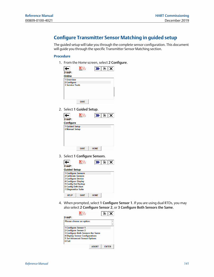
Configure Transmitter Sensor Matching in guided setupThe guided setup will take you through the complete sensor configuration. This documentwill guide you through the specific Transmitter Sensor Matching section.
Procedure
1. From the Home screen, select 2 Configure.
2. Select 1 Guided Setup.
3. Select 1 Configure Sensors.
4. When prompted, select 1 Configure Sensor 1. If you are using dual RTDs, you mayalso select 2 Configure Sensor 2, or 3 Configure Both Sensors the Same.
Reference Manual HART Commissioning00809-0100-4021 December 2019
Reference Manual 141
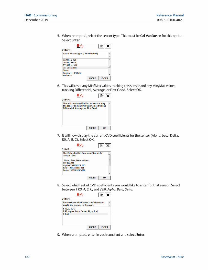
5. When prompted, select the sensor type. This must be Cal VanDusen for this option.Select Enter.
6. This will reset any Min/Max values tracking this sensor and any Min/Max valuestracking Differential, Average, or First Good. Select OK.
7. It will now display the current CVD coefficients for the sensor (Alpha, beta, Delta,R0, A, B, C). Select OK.
8. Select which set of CVD coefficients you would like to enter for that sensor. Selectbetween 1 R0, A, B, C, and 2 R0, Alpha, Beta, Delta.
9. When prompted, enter in each constant and select Enter.
HART Commissioning Reference ManualDecember 2019 00809-0100-4021
142 Rosemount 3144P
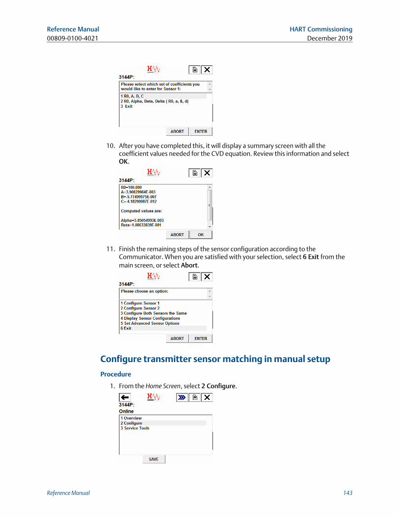
10. After you have completed this, it will display a summary screen with all thecoefficient values needed for the CVD equation. Review this information and selectOK.
11. Finish the remaining steps of the sensor configuration according to theCommunicator. When you are satisfied with your selection, select 6 Exit from themain screen, or select Abort.
Configure transmitter sensor matching in manual setup
Procedure
1. From the Home Screen, select 2 Configure.
Reference Manual HART Commissioning00809-0100-4021 December 2019
Reference Manual 143
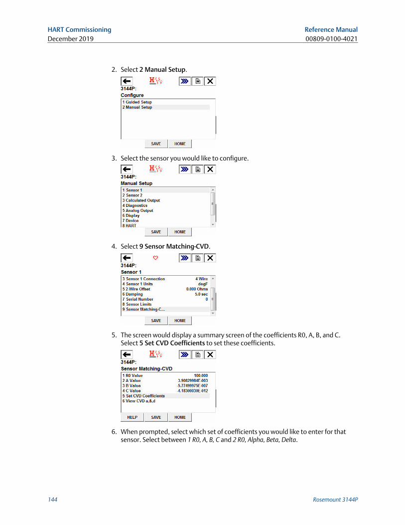
2. Select 2 Manual Setup.
3. Select the sensor you would like to configure.
4. Select 9 Sensor Matching-CVD.
5. The screen would display a summary screen of the coefficients R0, A, B, and C.Select 5 Set CVD Coefficients to set these coefficients.
6. When prompted, select which set of coefficients you would like to enter for thatsensor. Select between 1 R0, A, B, C and 2 R0, Alpha, Beta, Delta.
HART Commissioning Reference ManualDecember 2019 00809-0100-4021
144 Rosemount 3144P
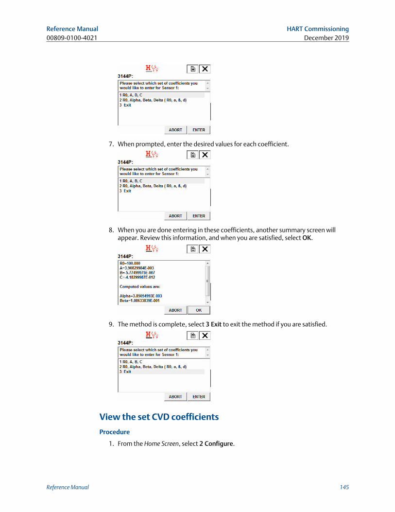
7. When prompted, enter the desired values for each coefficient.
8. When you are done entering in these coefficients, another summary screen willappear. Review this information, and when you are satisfied, select OK.
9. The method is complete, select 3 Exit to exit the method if you are satisfied.
View the set CVD coefficients
Procedure
1. From the Home Screen, select 2 Configure.
Reference Manual HART Commissioning00809-0100-4021 December 2019
Reference Manual 145
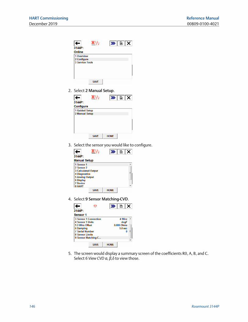
2. Select 2 Manual Setup.
3. Select the sensor you would like to configure.
4. Select 9 Sensor Matching-CVD.
5. The screen would display a summary screen of the coefficients R0, A, B, and C.Select 6 View CVD ɑ, β,δ to view those.
HART Commissioning Reference ManualDecember 2019 00809-0100-4021
146 Rosemount 3144P
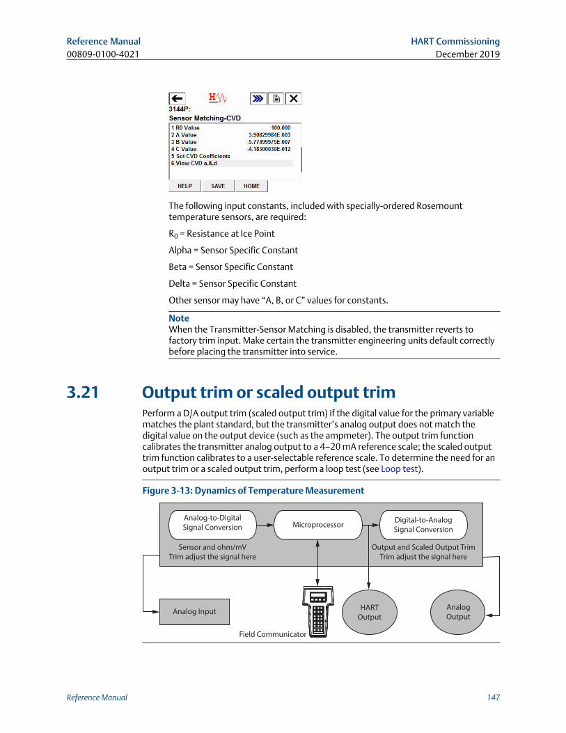
The following input constants, included with specially-ordered Rosemounttemperature sensors, are required:
R0 = Resistance at Ice Point
Alpha = Sensor Specific Constant
Beta = Sensor Specific Constant
Delta = Sensor Specific Constant
Other sensor may have “A, B, or C” values for constants.
NoteWhen the Transmitter-Sensor Matching is disabled, the transmitter reverts tofactory trim input. Make certain the transmitter engineering units default correctlybefore placing the transmitter into service.
3.21 Output trim or scaled output trimPerform a D/A output trim (scaled output trim) if the digital value for the primary variablematches the plant standard, but the transmitter’s analog output does not match thedigital value on the output device (such as the ampmeter). The output trim functioncalibrates the transmitter analog output to a 4–20 mA reference scale; the scaled outputtrim function calibrates to a user-selectable reference scale. To determine the need for anoutput trim or a scaled output trim, perform a loop test (see Loop test).
Figure 3-13: Dynamics of Temperature Measurement
Analog-to-Digital
Signal Conversion MicroprocessorDigital-to-Analog
Signal Conversion
Sensor and ohm/mV
Trim adjust the signal here
Output and Scaled Output Trim
Trim adjust the signal here
Analog InputHART
Output
Analog
Output
Field Communicator
Reference Manual HART Commissioning00809-0100-4021 December 2019
Reference Manual 147
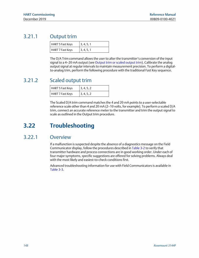
3.21.1 Output trimHART 5 Fast Keys 3, 4, 5, 1
HART 7 Fast Keys 3, 4, 5, 1
The D/A Trim command allows the user to alter the transmitter’s conversion of the inputsignal to a 4–20 mA output (see Output trim or scaled output trim). Calibrate the analogoutput signal at regular intervals to maintain measurement precision. To perform a digital-to-analog trim, perform the following procedure with the traditional Fast Key sequence.
3.21.2 Scaled output trimHART 5 Fast Keys 3, 4, 5, 2
HART 7 Fast Keys 3, 4, 5, 2
The Scaled D/A trim command matches the 4 and 20 mA points to a user-selectablereference scale other than 4 and 20 mA (2–10 volts, for example). To perform a scaled D/Atrim, connect an accurate reference meter to the transmitter and trim the output signal toscale as outlined in the Output trim procedure.
3.22 Troubleshooting
3.22.1 OverviewIf a malfunction is suspected despite the absence of a diagnostics message on the FieldCommunicator display, follow the procedures described in Table 3-2 to verify thattransmitter hardware and process connections are in good working order. Under each offour major symptoms, specific suggestions are offered for solving problems. Always dealwith the most likely and easiest-to-check conditions first.
Advanced troubleshooting information for use with Field Communicators is available inTable 3-3.
HART Commissioning Reference ManualDecember 2019 00809-0100-4021
148 Rosemount 3144P
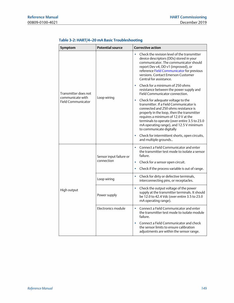
Table 3-2: HART/4–20 mA Basic Troubleshooting
Symptom Potential source Corrective action
Transmitter does notcommunicate withField Communicator
Loop wiring
• Check the revision level of the transmitterdevice descriptors (DDs) stored in yourcommunicator. The communicator shouldreport Dev v4, DD v1 (improved), orreference Field Communicator for previousversions. Contact Emerson CustomerCentral for assistance.
• Check for a minimum of 250 ohmsresistance between the power supply andField Communicator connection.
• Check for adequate voltage to thetransmitter. If a Field Communicator isconnected and 250 ohms resistance isproperly in the loop, then the transmitterrequires a minimum of 12.0 V at theterminals to operate (over entire 3.5 to 23.0mA operating range), and 12.5 V minimumto communicate digitally
• Check for intermittent shorts, open circuits,and multiple grounds..
High output
Sensor input failure orconnection
• Connect a Field Communicator and enterthe transmitter test mode to isolate a sensorfailure.
• Check for a sensor open circuit.
• Check if the process variable is out of range.
Loop wiring• Check for dirty or defective terminals,
interconnecting pins, or receptacles.
Power supply
• Check the output voltage of the powersupply at the transmitter terminals. It shouldbe 12.0 to 42.4 Vdc (over entire 3.5 to 23.0mA operating range).
Electronics module • Connect a Field Communicator and enterthe transmitter test mode to isolate modulefailure.
• Connect a Field Communicator and checkthe sensor limits to ensure calibrationadjustments are within the sensor range.
Reference Manual HART Commissioning00809-0100-4021 December 2019
Reference Manual 149
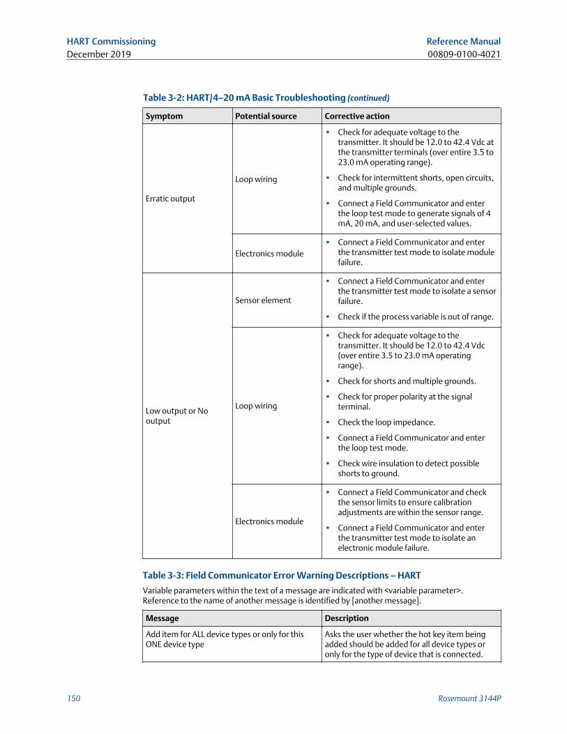
Table 3-2: HART/4–20 mA Basic Troubleshooting (continued)
Symptom Potential source Corrective action
Erratic output
Loop wiring
• Check for adequate voltage to thetransmitter. It should be 12.0 to 42.4 Vdc atthe transmitter terminals (over entire 3.5 to23.0 mA operating range).
• Check for intermittent shorts, open circuits,and multiple grounds.
• Connect a Field Communicator and enterthe loop test mode to generate signals of 4mA, 20 mA, and user-selected values.
Electronics module• Connect a Field Communicator and enter
the transmitter test mode to isolate modulefailure.
Low output or Nooutput
Sensor element
• Connect a Field Communicator and enterthe transmitter test mode to isolate a sensorfailure.
• Check if the process variable is out of range.
Loop wiring
• Check for adequate voltage to thetransmitter. It should be 12.0 to 42.4 Vdc(over entire 3.5 to 23.0 mA operatingrange).
• Check for shorts and multiple grounds.
• Check for proper polarity at the signalterminal.
• Check the loop impedance.
• Connect a Field Communicator and enterthe loop test mode.
• Check wire insulation to detect possibleshorts to ground.
Electronics module
• Connect a Field Communicator and checkthe sensor limits to ensure calibrationadjustments are within the sensor range.
• Connect a Field Communicator and enterthe transmitter test mode to isolate anelectronic module failure.
Table 3-3: Field Communicator Error Warning Descriptions – HART
Variable parameters within the text of a message are indicated with <variable parameter>.Reference to the name of another message is identified by [another message].
Message Description
Add item for ALL device types or only for thisONE device type
Asks the user whether the hot key item beingadded should be added for all device types oronly for the type of device that is connected.
HART Commissioning Reference ManualDecember 2019 00809-0100-4021
150 Rosemount 3144P
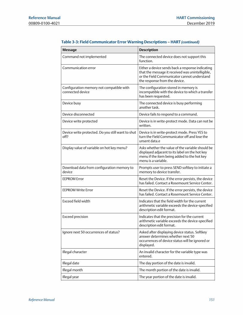
Table 3-3: Field Communicator Error Warning Descriptions – HART (continued)
Message Description
Command not implemented The connected device does not support thisfunction.
Communication error Either a device sends back a response indicatingthat the message it received was unintelligible,or the Field Communicator cannot understandthe response from the device.
Configuration memory not compatible withconnected device
The configuration stored in memory isincompatible with the device to which a transferhas been requested.
Device busy The connected device is busy performinganother task.
Device disconnected Device fails to respond to a command.
Device write protected Device is in write-protect mode. Data can not bewritten.
Device write protected. Do you still want to shutoff?
Device is in write-protect mode. Press YES toturn the Field Communicator off and lose theunsent data.e
Display value of variable on hot key menu? Asks whether the value of the variable should bedisplayed adjacent to its label on the hot keymenu if the item being added to the hot keymenu is a variable.
Download data from configuration memory todevice
Prompts user to press SEND softkey to initiate amemory to device transfer.
EEPROM Error Reset the Device. If the error persists, the devicehas failed. Contact a Rosemount Service Center.
EEPROM Write Error Reset the Device. If the error persists, the devicehas failed. Contact a Rosemount Service Center.
Exceed field width Indicates that the field width for the currentarithmetic variable exceeds the device-specifieddescription edit format.
Exceed precision Indicates that the precision for the currentarithmetic variable exceeds the device-specifieddescription edit format.
Ignore next 50 occurrences of status? Asked after displaying device status. Softkeyanswer determines whether next 50occurrences of device status will be ignored ordisplayed.
Illegal character An invalid character for the variable type wasentered.
Illegal date The day portion of the date is invalid.
Illegal month The month portion of the date is invalid.
Illegal year The year portion of the date is invalid.
Reference Manual HART Commissioning00809-0100-4021 December 2019
Reference Manual 151
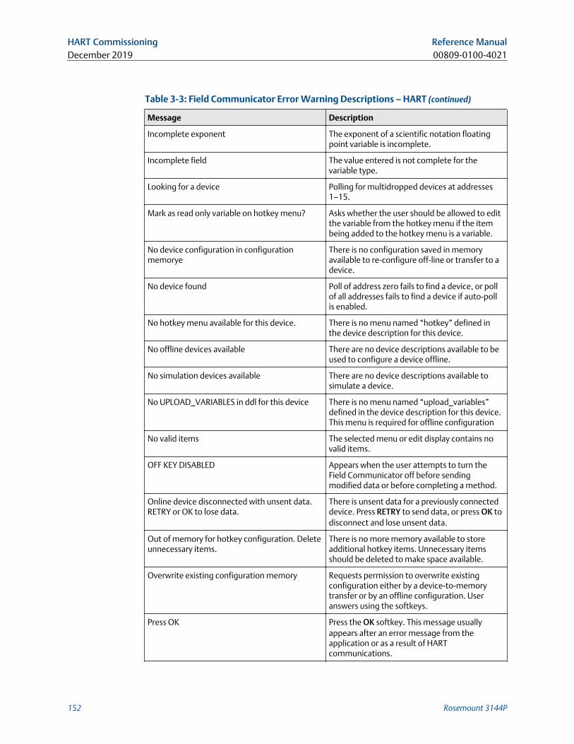
Table 3-3: Field Communicator Error Warning Descriptions – HART (continued)
Message Description
Incomplete exponent The exponent of a scientific notation floatingpoint variable is incomplete.
Incomplete field The value entered is not complete for thevariable type.
Looking for a device Polling for multidropped devices at addresses1–15.
Mark as read only variable on hotkey menu? Asks whether the user should be allowed to editthe variable from the hotkey menu if the itembeing added to the hotkey menu is a variable.
No device configuration in configurationmemorye
There is no configuration saved in memoryavailable to re-configure off-line or transfer to adevice.
No device found Poll of address zero fails to find a device, or pollof all addresses fails to find a device if auto-pollis enabled.
No hotkey menu available for this device. There is no menu named “hotkey” defined inthe device description for this device.
No offline devices available There are no device descriptions available to beused to configure a device offline.
No simulation devices available There are no device descriptions available tosimulate a device.
No UPLOAD_VARIABLES in ddl for this device There is no menu named “upload_variables”defined in the device description for this device.This menu is required for offline configuration
No valid items The selected menu or edit display contains novalid items.
OFF KEY DISABLED Appears when the user attempts to turn theField Communicator off before sendingmodified data or before completing a method.
Online device disconnected with unsent data.RETRY or OK to lose data.
There is unsent data for a previously connecteddevice. Press RETRY to send data, or press OK todisconnect and lose unsent data.
Out of memory for hotkey configuration. Deleteunnecessary items.
There is no more memory available to storeadditional hotkey items. Unnecessary itemsshould be deleted to make space available.
Overwrite existing configuration memory Requests permission to overwrite existingconfiguration either by a device-to-memorytransfer or by an offline configuration. Useranswers using the softkeys.
Press OK Press the OK softkey. This message usuallyappears after an error message from theapplication or as a result of HARTcommunications.
HART Commissioning Reference ManualDecember 2019 00809-0100-4021
152 Rosemount 3144P
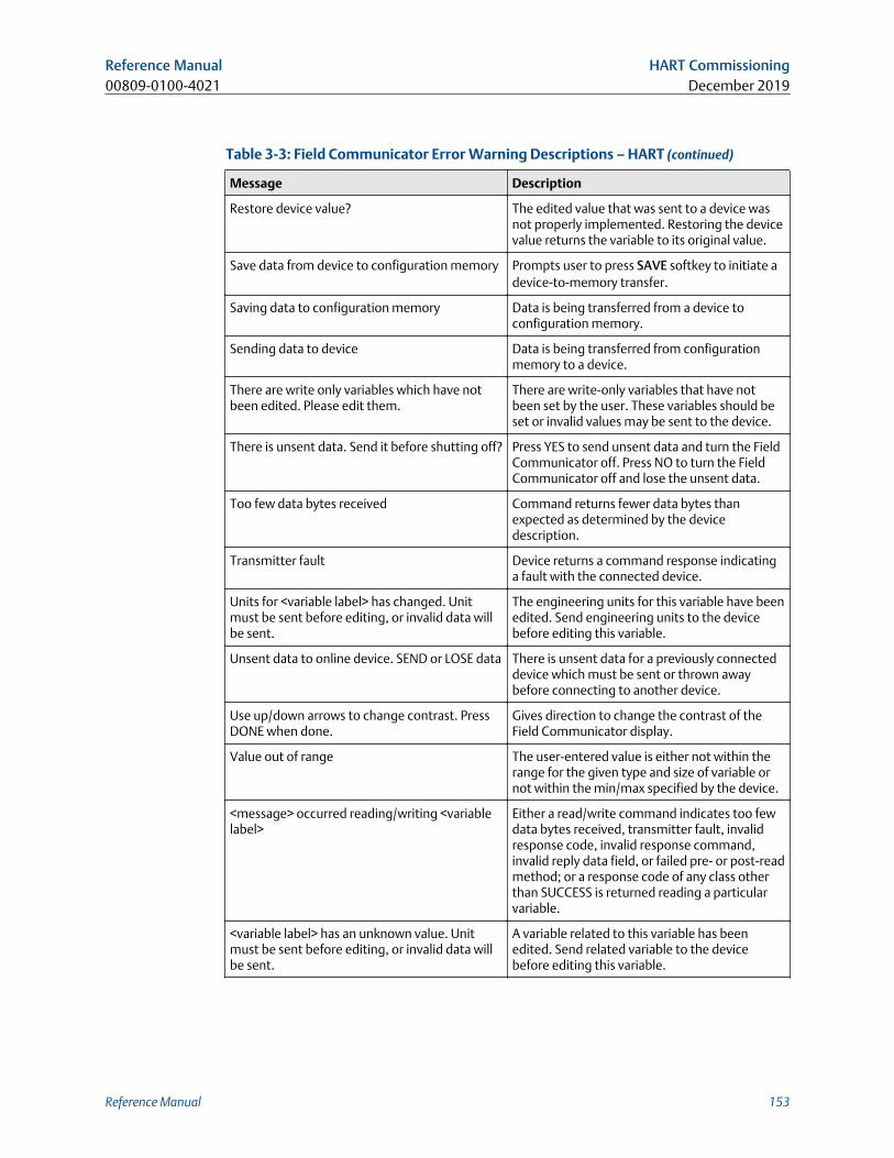
Table 3-3: Field Communicator Error Warning Descriptions – HART (continued)
Message Description
Restore device value? The edited value that was sent to a device wasnot properly implemented. Restoring the devicevalue returns the variable to its original value.
Save data from device to configuration memory Prompts user to press SAVE softkey to initiate adevice-to-memory transfer.
Saving data to configuration memory Data is being transferred from a device toconfiguration memory.
Sending data to device Data is being transferred from configurationmemory to a device.
There are write only variables which have notbeen edited. Please edit them.
There are write-only variables that have notbeen set by the user. These variables should beset or invalid values may be sent to the device.
There is unsent data. Send it before shutting off? Press YES to send unsent data and turn the FieldCommunicator off. Press NO to turn the FieldCommunicator off and lose the unsent data.
Too few data bytes received Command returns fewer data bytes thanexpected as determined by the devicedescription.
Transmitter fault Device returns a command response indicatinga fault with the connected device.
Units for <variable label> has changed. Unitmust be sent before editing, or invalid data willbe sent.
The engineering units for this variable have beenedited. Send engineering units to the devicebefore editing this variable.
Unsent data to online device. SEND or LOSE data There is unsent data for a previously connecteddevice which must be sent or thrown awaybefore connecting to another device.
Use up/down arrows to change contrast. PressDONE when done.
Gives direction to change the contrast of theField Communicator display.
Value out of range The user-entered value is either not within therange for the given type and size of variable ornot within the min/max specified by the device.
<message> occurred reading/writing <variablelabel>
Either a read/write command indicates too fewdata bytes received, transmitter fault, invalidresponse code, invalid response command,invalid reply data field, or failed pre- or post-readmethod; or a response code of any class otherthan SUCCESS is returned reading a particularvariable.
<variable label> has an unknown value. Unitmust be sent before editing, or invalid data willbe sent.
A variable related to this variable has beenedited. Send related variable to the devicebefore editing this variable.
Reference Manual HART Commissioning00809-0100-4021 December 2019
Reference Manual 153
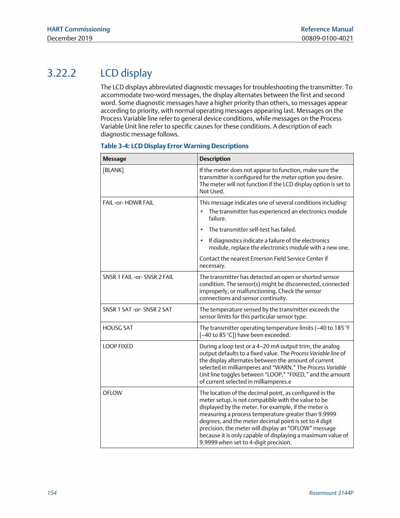
3.22.2 LCD displayThe LCD displays abbreviated diagnostic messages for troubleshooting the transmitter. Toaccommodate two-word messages, the display alternates between the first and secondword. Some diagnostic messages have a higher priority than others, so messages appearaccording to priority, with normal operating messages appearing last. Messages on theProcess Variable line refer to general device conditions, while messages on the ProcessVariable Unit line refer to specific causes for these conditions. A description of eachdiagnostic message follows.
Table 3-4: LCD Display Error Warning Descriptions
Message Description
[BLANK] If the meter does not appear to function, make sure thetransmitter is configured for the meter option you desire.The meter will not function if the LCD display option is set toNot Used.
FAIL -or- HDWR FAIL This message indicates one of several conditions including:
• The transmitter has experienced an electronics modulefailure.
• The transmitter self-test has failed.
• If diagnostics indicate a failure of the electronicsmodule, replace the electronics module with a new one.
Contact the nearest Emerson Field Service Center ifnecessary.
SNSR 1 FAIL -or- SNSR 2 FAIL The transmitter has detected an open or shorted sensorcondition. The sensor(s) might be disconnected, connectedimproperly, or malfunctioning. Check the sensorconnections and sensor continuity.
SNSR 1 SAT -or- SNSR 2 SAT The temperature sensed by the transmitter exceeds thesensor limits for this particular sensor type.
HOUSG SAT The transmitter operating temperature limits (–40 to 185 °F[–40 to 85 °C]) have been exceeded.
LOOP FIXED During a loop test or a 4–20 mA output trim, the analogoutput defaults to a fixed value. The Process Variable line ofthe display alternates between the amount of currentselected in milliamperes and “WARN.” The Process VariableUnit line toggles between “LOOP,” “FIXED,” and the amountof current selected in milliamperes.e
OFLOW The location of the decimal point, as configured in themeter setup, is not compatible with the value to bedisplayed by the meter. For example, if the meter ismeasuring a process temperature greater than 9.9999degrees, and the meter decimal point is set to 4 digitprecision, the meter will display an “OFLOW” messagebecause it is only capable of displaying a maximum value of9.9999 when set to 4-digit precision.
HART Commissioning Reference ManualDecember 2019 00809-0100-4021
154 Rosemount 3144P
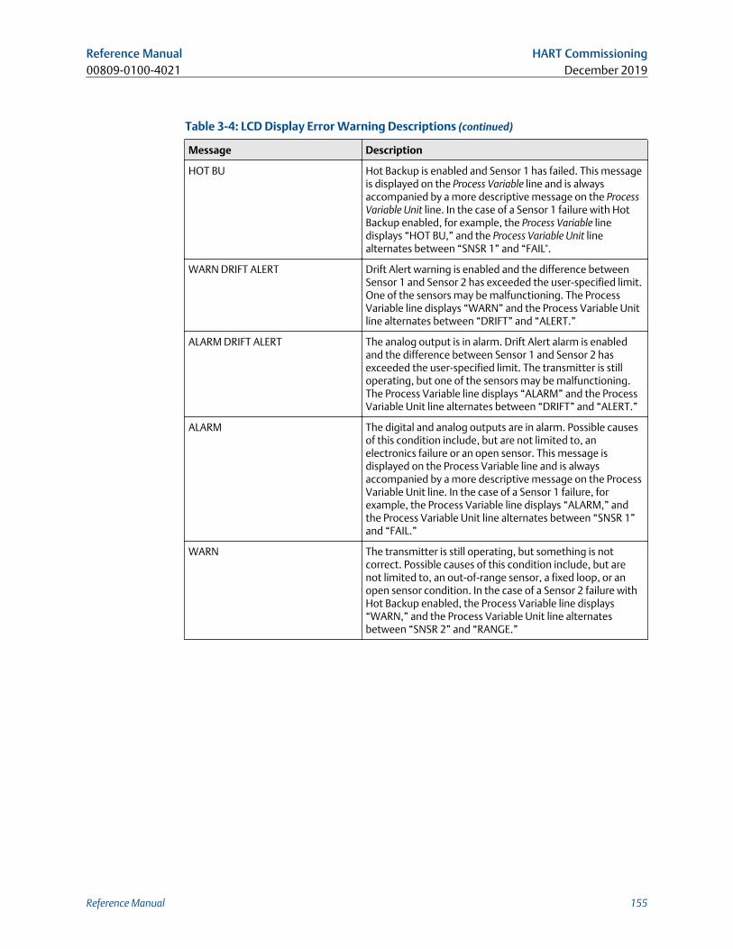
Table 3-4: LCD Display Error Warning Descriptions (continued)
Message Description
HOT BU Hot Backup is enabled and Sensor 1 has failed. This messageis displayed on the Process Variable line and is alwaysaccompanied by a more descriptive message on the ProcessVariable Unit line. In the case of a Sensor 1 failure with HotBackup enabled, for example, the Process Variable linedisplays “HOT BU,” and the Process Variable Unit linealternates between “SNSR 1” and “FAIL".
WARN DRIFT ALERT Drift Alert warning is enabled and the difference betweenSensor 1 and Sensor 2 has exceeded the user-specified limit.One of the sensors may be malfunctioning. The ProcessVariable line displays “WARN” and the Process Variable Unitline alternates between “DRIFT” and “ALERT.”
ALARM DRIFT ALERT The analog output is in alarm. Drift Alert alarm is enabledand the difference between Sensor 1 and Sensor 2 hasexceeded the user-specified limit. The transmitter is stilloperating, but one of the sensors may be malfunctioning.The Process Variable line displays “ALARM” and the ProcessVariable Unit line alternates between “DRIFT” and “ALERT.”
ALARM The digital and analog outputs are in alarm. Possible causesof this condition include, but are not limited to, anelectronics failure or an open sensor. This message isdisplayed on the Process Variable line and is alwaysaccompanied by a more descriptive message on the ProcessVariable Unit line. In the case of a Sensor 1 failure, forexample, the Process Variable line displays “ALARM,” andthe Process Variable Unit line alternates between “SNSR 1”and “FAIL.”
WARN The transmitter is still operating, but something is notcorrect. Possible causes of this condition include, but arenot limited to, an out-of-range sensor, a fixed loop, or anopen sensor condition. In the case of a Sensor 2 failure withHot Backup enabled, the Process Variable line displays“WARN,” and the Process Variable Unit line alternatesbetween “SNSR 2” and “RANGE.”
Reference Manual HART Commissioning00809-0100-4021 December 2019
Reference Manual 155

HART Commissioning Reference ManualDecember 2019 00809-0100-4021
156 Rosemount 3144P
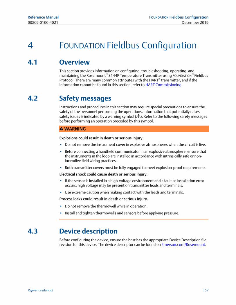
4 FOUNDATION Fieldbus Configuration
4.1 OverviewThis section provides information on configuring, troubleshooting, operating, andmaintaining the Rosemount™ 3144P Temperature Transmitter using FOUNDATION™ FieldbusProtocol. There are many common attributes with the HART® transmitter, and if theinformation cannot be found in this section, refer to HART Commissioning.
4.2 Safety messagesInstructions and procedures in this section may require special precautions to ensure thesafety of the personnel performing the operations. Information that potentially raisessafety issues is indicated by a warning symbol ( ). Refer to the following safety messagesbefore performing an operation preceded by this symbol.
WARNING
Explosions could result in death or serious injury.
• Do not remove the instrument cover in explosive atmospheres when the circuit is live.
• Before connecting a handheld communicator in an explosive atmosphere, ensure thatthe instruments in the loop are installed in accordance with intrinsically safe or non-incendive field wiring practices.
• Both transmitter covers must be fully engaged to meet explosion-proof requirements.
Electrical shock could cause death or serious injury.
• If the sensor is installed in a high-voltage environment and a fault or installation erroroccurs, high voltage may be present on transmitter leads and terminals.
• Use extreme caution when making contact with the leads and terminals.
Process leaks could result in death or serious injury.
• Do not remove the thermowell while in operation.
• Install and tighten thermowells and sensors before applying pressure.
4.3 Device descriptionBefore configuring the device, ensure the host has the appropriate Device Description filerevision for this device. The device descriptor can be found on Emerson.com/Rosemount.
Reference Manual FOUNDATION Fieldbus Configuration00809-0100-4021 December 2019
Reference Manual 157
As of February 2011, the current revision of the Rosemount 3144P with FOUNDATION
Fieldbus Protocol is device revision 3.
4.4 Node addressThe transmitter is shipped at a temporary (248) address. This will enable FOUNDATION
Fieldbus host systems to automatically recognize the device and move it to a permanentaddress.
4.5 ModesThe resource, transducer, and all function blocks in the device have modes of operation.These modes govern the operation of the block. Every block supports both automatic(AUTO) and out of service (OOS) modes. Other modes may also be supported.
4.5.1 Changing modesTo change the operating mode, set the MODE_BLK.TARGET to the desired mode. After ashort delay, the parameter MODE_BLOCK.ACTUAL should reflect the mode change if theblock is operating properly.
4.5.2 Permitted modesIt is possible to prevent unauthorized changes to the operating mode of a block. To dothis, configure MODE_BLOCK.PERMITTED to allow only the desired operating modes. It isrecommended to always select OOS as one of the permitted modes.
4.5.3 Types of modesFor the procedures described in this manual, it will be helpful to understand the followingmodes:
AUTO
The functions performed by the block will execute. If the block has any outputs, these willcontinue to update. This is typically the normal operating mode.
Out of service (OOS)
The functions performed by the block will not execute. If the block has any outputs, thesewill typically not update and the status of any values passed to downstream blocks will be“BAD.” To make some changes to the configuration of the block, change the mode of theblock to OOS. When the changes are complete, change the mode back to AUTO.
MAN
In this mode, variables that are passed out of the block can be manually set for testing oroverride purposes.
FOUNDATION Fieldbus Configuration Reference ManualDecember 2019 00809-0100-4021
158 Rosemount 3144P
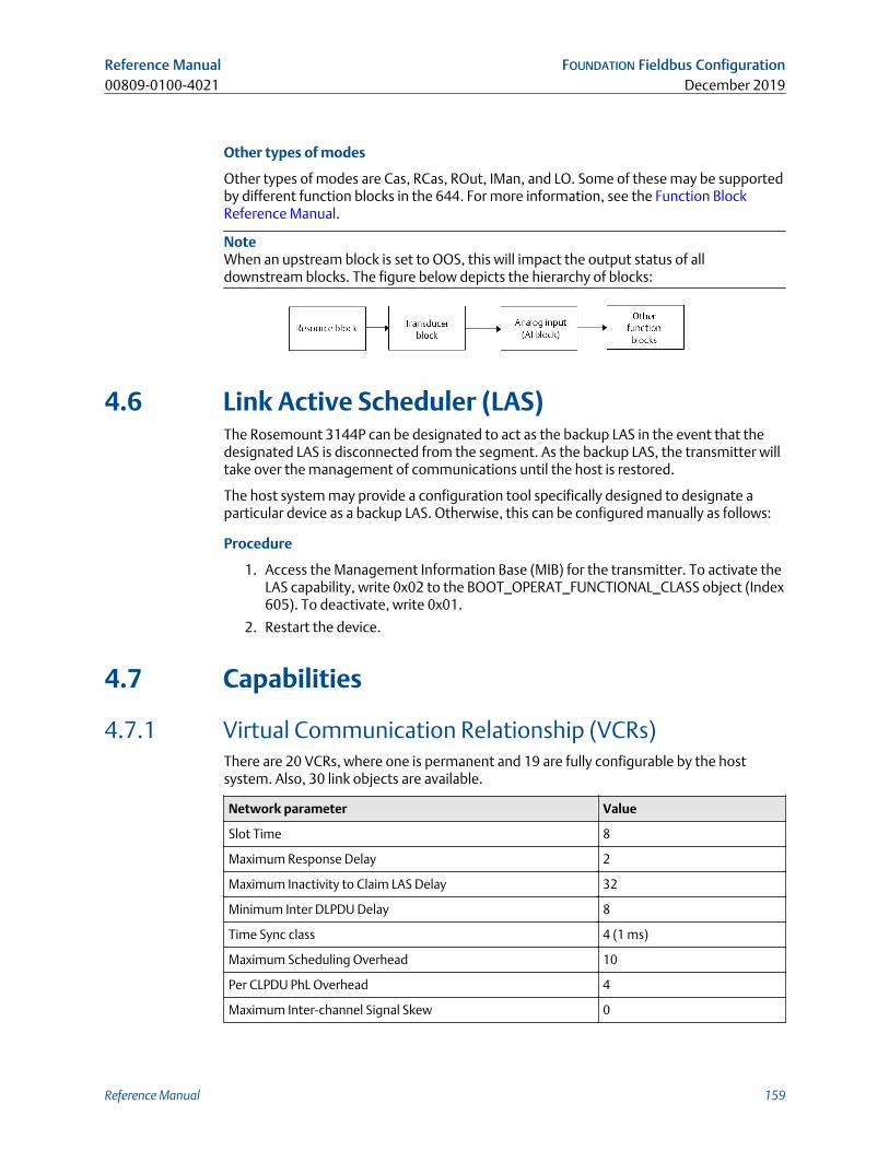
Other types of modes
Other types of modes are Cas, RCas, ROut, IMan, and LO. Some of these may be supportedby different function blocks in the 644. For more information, see the Function BlockReference Manual.
NoteWhen an upstream block is set to OOS, this will impact the output status of alldownstream blocks. The figure below depicts the hierarchy of blocks:
4.6 Link Active Scheduler (LAS)The Rosemount 3144P can be designated to act as the backup LAS in the event that thedesignated LAS is disconnected from the segment. As the backup LAS, the transmitter willtake over the management of communications until the host is restored.
The host system may provide a configuration tool specifically designed to designate aparticular device as a backup LAS. Otherwise, this can be configured manually as follows:
Procedure
1. Access the Management Information Base (MIB) for the transmitter. To activate theLAS capability, write 0x02 to the BOOT_OPERAT_FUNCTIONAL_CLASS object (Index605). To deactivate, write 0x01.
2. Restart the device.
4.7 Capabilities
4.7.1 Virtual Communication Relationship (VCRs)There are 20 VCRs, where one is permanent and 19 are fully configurable by the hostsystem. Also, 30 link objects are available.
Network parameter Value
Slot Time 8
Maximum Response Delay 2
Maximum Inactivity to Claim LAS Delay 32
Minimum Inter DLPDU Delay 8
Time Sync class 4 (1 ms)
Maximum Scheduling Overhead 10
Per CLPDU PhL Overhead 4
Maximum Inter-channel Signal Skew 0
Reference Manual FOUNDATION Fieldbus Configuration00809-0100-4021 December 2019
Reference Manual 159
Network parameter Value
Required Number of Post-transmission-gab-ext Units 0
Required Number of Preamble-extension Units 1
Block Execution times
Block Execution time
Resource N/A
Transducer N/A
LCD display Block N/A
Advanced Diagnostics N/A
Analog Input 1, 2, 3 60 ms
PID 1 and 2 with Autotune 90 ms
Input Selector 65 ms
Signal Characterizer 60 ms
Arithmetic 60 ms
Output Splitter 60 ms
4.8 FOUNDATION Fieldbus function blocksFor reference information on the resource, sensor transducer, AI, LCD display transducerblocks refer to Rosemount 3144P Temperature Transmitter Product Data Sheet.Reference information on the PID block can be found in the Function Block ReferenceManual.
4.8.1 Resource block (index number 1000)The resource function block (RB) contains diagnostic, hardware, and electronicsinformation. There are no linkable inputs or outputs to the resource block.
4.8.2 Sensor transducer block (index number 1100)The Sensor Transducer Function Block (STB) temperature measurement data, includessensor and terminal (body) temperature. The STB also includes information about sensortype, engineering units, linearization, reranging, damping, temperature compensation,and diagnostics. Transmitter Revision 3 and above also contain Hot Backup™ functionalityin the STB.
FOUNDATION Fieldbus Configuration Reference ManualDecember 2019 00809-0100-4021
160 Rosemount 3144P
4.8.3 LCD display transducer block (index number 1200)The LCD display transducer block is used to configure the LCD display.
4.8.4 Analog input block (index number 1400, 1500, 1600,and 1700)The Analog Input Function Block (AI) processes the measurements from the sensor andmakes them available to other function blocks. The output value from the AI block is inengineering units and contains a status indicating the quality of the measurement. The AIblock is used for scaling functionality.
4.8.5 PID block (index number 1800 and 1900)The PID function block combines all of the necessary logic to perform proportional/integral/derivative (PID) control. The block supports mode control, signal scaling andlimiting, feed forward control, override tracking, alarm limit detection, and signal statuspropagation.
The block supports two forms of the PID equation: Standard and Series. Choose theappropriate equation using the MATHFORM parameter. The Standard ISA PID equation isthe default selection and autotune.
4.8.6 Input selector (index number 2000)The signal selector block provides selection of up to four inputs and generates an outputbased on the configured action. This block normally receives its inputs from AI blocks. Theblock performs maximum, minimum, middle, average, and ‘first good’ signal selection.
4.8.7 Output splitter (index number OSPL 2300)The output splitter block provides the capability to drive two control outputs from a singleinput. Each output is a linear function of some portion of the input.
4.8.8 Arithmetic (index number 2200)This block is designed to permit simple use of popular measurement math functions. Theuser does not have to know how to write equations. The math algorithm is selected byname, chosen by the user for the function to be done.
4.8.9 Signal characterizer (index number 2100)The signal characterizer block has two sections, each with an output that is a non-linearfunction of the respective input. The non-linear function is determined by a single look-up
Reference Manual FOUNDATION Fieldbus Configuration00809-0100-4021 December 2019
Reference Manual 161
table with 21 arbitrary x-y pairs. The status of an input is copied to the correspondingoutput, so the block may be used in the control or process signal path.
4.9 Resource block
4.9.1 Features and Features_SelThe FEATURES and FEATURE_SEL parameters determine optional behavior of thetransmitter.
FEATURES
The FEATURES parameter is read only and defines which features are supported by thetransmitter. Below is a list of the FEATURES the transmitter supports.
UNICODE
All configurable string variables in the transmitter, except tag names, are octet strings.Either ASCII or Unicode may be used. If the configuration device is generating Unicodeoctet strings, you must set the Unicode option bit.
REPORTS
The transmitter supports alert reports. The Reports option bit must be set in the featuresbit string to use this feature. If it is not set, the host must poll for alerts.
SOFT W LOCK
Inputs to the security and write lock functions include the software write lock bits of theFEATURE_SEL parameter, the WRITE_LOCK parameter, and the DEFINE_WRITE_LOCKparameter.
The WRITE_LOCK parameter prevents modification of parameters within the deviceexcept to clear the WRITE_LOCK parameter. During this time, the block will functionnormally updating inputs and outputs and executing algorithms. When the WRITE_LOCKcondition is cleared, a WRITE_ALM alert is generated with a priority that corresponds tothe WRITE_PRI parameter.
The FEATURE_SEL parameter enables the user to select the software write lock or no writelock capability. In order to enable the software write lock, the SOFT_W_LOCK bit must beset in the FEATURE_SEL parameter. Once this bit is set, the WRITE_LOCK parameter maybe set to “Locked” or “Unlocked.” Once the WRITE_LOCK parameter is set to “Locked” bythe software, all user requested writes as determined by the DEFINE_WRITE_LOCKparameter shall be rejected.
The DEFINE_WRITE_LOCK parameter allows the user to configure whether the write lockfunction will control writing to all blocks, or only to the resource and transducer blocks.Internally updated data such as process variables and diagnostics will not be restricted.N/A = No blocks are blocked Physical = Locks resource and transducer block Everything =Locks every block.
The following table displays all possible configurations of the WRITE_LOCK parameter.
FOUNDATION Fieldbus Configuration Reference ManualDecember 2019 00809-0100-4021
162 Rosemount 3144P
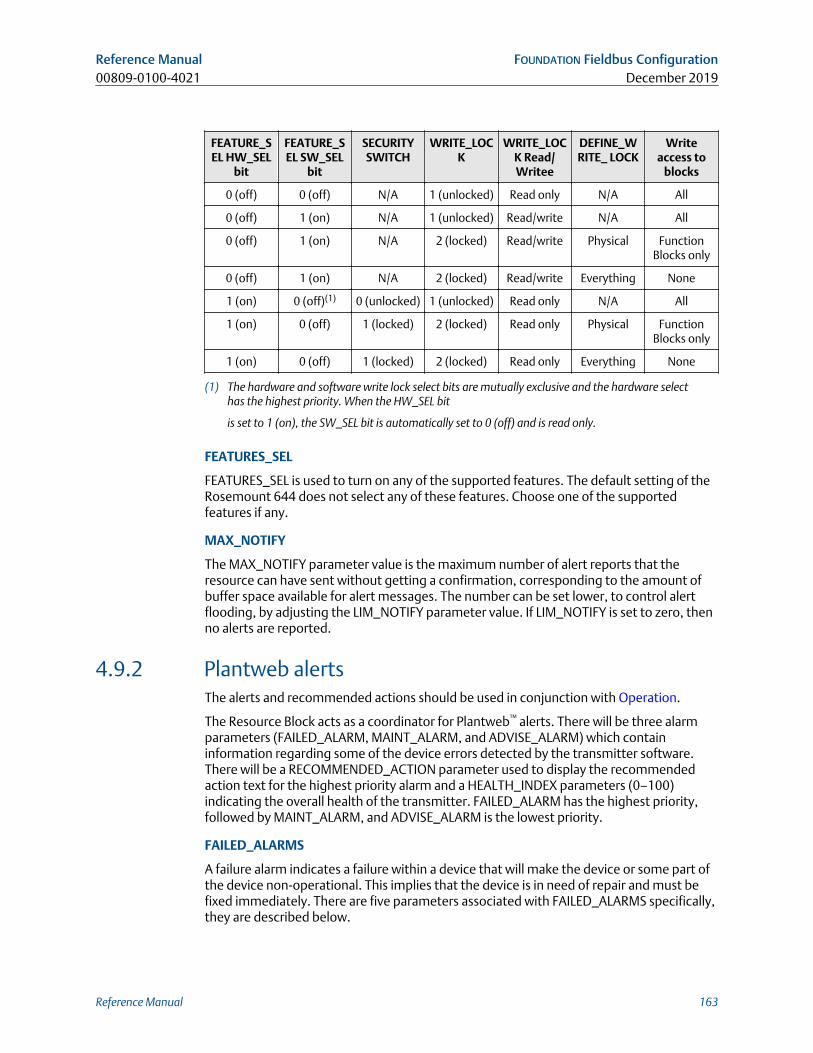
FEATURE_SEL HW_SEL
bit
FEATURE_SEL SW_SEL
bit
SECURITYSWITCH
WRITE_LOCK
WRITE_LOCK Read/Writee
DEFINE_WRITE_ LOCK
Writeaccess to
blocks
0 (off) 0 (off) N/A 1 (unlocked) Read only N/A All
0 (off) 1 (on) N/A 1 (unlocked) Read/write N/A All
0 (off) 1 (on) N/A 2 (locked) Read/write Physical FunctionBlocks only
0 (off) 1 (on) N/A 2 (locked) Read/write Everything None
1 (on) 0 (off)(1) 0 (unlocked) 1 (unlocked) Read only N/A All
1 (on) 0 (off) 1 (locked) 2 (locked) Read only Physical FunctionBlocks only
1 (on) 0 (off) 1 (locked) 2 (locked) Read only Everything None
(1) The hardware and software write lock select bits are mutually exclusive and the hardware selecthas the highest priority. When the HW_SEL bit
is set to 1 (on), the SW_SEL bit is automatically set to 0 (off) and is read only.
FEATURES_SEL
FEATURES_SEL is used to turn on any of the supported features. The default setting of theRosemount 644 does not select any of these features. Choose one of the supportedfeatures if any.
MAX_NOTIFY
The MAX_NOTIFY parameter value is the maximum number of alert reports that theresource can have sent without getting a confirmation, corresponding to the amount ofbuffer space available for alert messages. The number can be set lower, to control alertflooding, by adjusting the LIM_NOTIFY parameter value. If LIM_NOTIFY is set to zero, thenno alerts are reported.
4.9.2 Plantweb alertsThe alerts and recommended actions should be used in conjunction with Operation.
The Resource Block acts as a coordinator for Plantweb™ alerts. There will be three alarmparameters (FAILED_ALARM, MAINT_ALARM, and ADVISE_ALARM) which containinformation regarding some of the device errors detected by the transmitter software.There will be a RECOMMENDED_ACTION parameter used to display the recommendedaction text for the highest priority alarm and a HEALTH_INDEX parameters (0–100)indicating the overall health of the transmitter. FAILED_ALARM has the highest priority,followed by MAINT_ALARM, and ADVISE_ALARM is the lowest priority.
FAILED_ALARMS
A failure alarm indicates a failure within a device that will make the device or some part ofthe device non-operational. This implies that the device is in need of repair and must befixed immediately. There are five parameters associated with FAILED_ALARMS specifically,they are described below.
Reference Manual FOUNDATION Fieldbus Configuration00809-0100-4021 December 2019
Reference Manual 163
FAILED_ENABLED
This parameter contains a list of failures in the device which makes the device non-operational that will cause an alert to be sent. Below is a list of the failures with the highestpriority first.
1. Electronics
2. NV memory
3. HW/SW incompatible
4. Primary value
5. Secondary value
FAILED_MASK
This parameter will mask any of the failed conditions listed in FAILED_ENABLED. A bit onmeans that the condition is masked out from alarming and will not be reported.
FAILED_PRI
Designates the alerting priority of the FAILED_ALM, see Process alarms. The default is 0and the recommended values are between 8 and 15.
FAILED_ACTIVE
This parameter displays which of the alarms is active. Only the alarm with the highestpriority will be displayed. This priority is not the same as the FAILED_PRI parameterdescribed above. This priority is hard coded within the device and is not user configurable.
FAILED_ALM
Alarm indicating a failure within a device which makes the device non-operational.
MAINT_ALARMS
A maintenance alarm indicates the device or some part of the device needs maintenancesoon. If the condition is ignored, the device will eventually fail. There are five parametersassociated with MAINT_ALARMS, they are described below.
MAINT_ENABLED
The MAINT_ENABLED parameter contains a list of conditions indicating the device or somepart of the device needs maintenance soon.
Below is a list of the conditions with the highest priority first.
1. Primary value degraded
2. Secondary value degraded
3. Diagnostic
4. Configuration error
5. Calibration error
FOUNDATION Fieldbus Configuration Reference ManualDecember 2019 00809-0100-4021
164 Rosemount 3144P
MAINT_MASK
The MAINT_MASK parameter will mask any of the failed conditions listed inMAINT_ENABLED. A bit on means that the condition is masked out from alarming and willnot be reported.
MAINT_PRI
MAINT_PRI designates the alarming priority of the MAINT_ALM, Process alarms. Thedefault is 0 and the recommended values is 3 to 7.
MAINT_ACTIVE
The MAINT_ACTIVE parameter displays which of the alarms is active. Only the conditionwith the highest priority will be displayed. This priority is not the same as the MAINT_PRIparameter described above. This priority is hard coded within the device and is not userconfigurable.
MAINT_ALM
An alarm indicating the device needs maintenance soon. If the condition is ignored, thedevice will eventually fail.
Advisory alarms
An advisory alarm indicates informative conditions that do not have a direct impact on thedevice's primary functions. There are five parameters associated with ADVISE_ALARMS.They are described below.
ADVISE_ENABLED
The ADVISE_ENABLED parameter contains a list of informative conditions that do not havea direct impact on the device's primary functions. Below is a list of the advisories with thehighest priority first.
1. NV writes deferred
2. SPM process anomaly detected
ADVISE_MASK
The ADVISE_MASK parameter will mask any of the failed conditions listed inADVISE_ENABLED. A bit on means the condition is masked out from alarming and will notbe reported.
ADVISE_PRI
ADVISE_PRI designates the alarming priority of the ADVISE_ALM, see Process alarms. Thedefault is 0 and the recommended values are 1 or 2.
ADVISE_ACTIVE
The ADVISE_ACTIVE parameter displays which of the advisories is active. Only the advisorywith the highest priority will be displayed. This priority is not the same as the ADVISE_PRIparameter described above. This priority is hard coded within the device and is not userconfigurable.
Reference Manual FOUNDATION Fieldbus Configuration00809-0100-4021 December 2019
Reference Manual 165
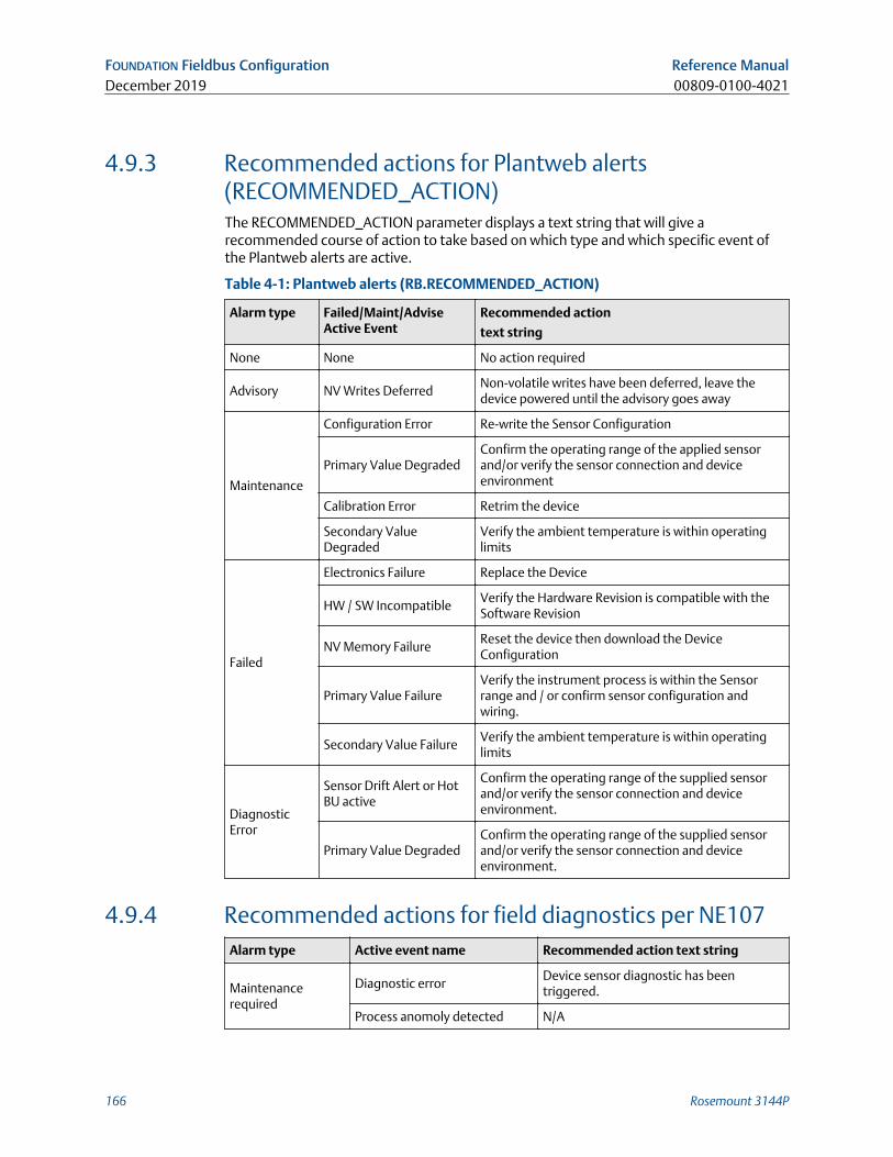
4.9.3 Recommended actions for Plantweb alerts(RECOMMENDED_ACTION)The RECOMMENDED_ACTION parameter displays a text string that will give arecommended course of action to take based on which type and which specific event ofthe Plantweb alerts are active.
Table 4-1: Plantweb alerts (RB.RECOMMENDED_ACTION)
Alarm type Failed/Maint/AdviseActive Event
Recommended action
text string
None None No action required
Advisory NV Writes DeferredNon-volatile writes have been deferred, leave thedevice powered until the advisory goes away
Maintenance
Configuration Error Re-write the Sensor Configuration
Primary Value DegradedConfirm the operating range of the applied sensorand/or verify the sensor connection and deviceenvironment
Calibration Error Retrim the device
Secondary ValueDegraded
Verify the ambient temperature is within operatinglimits
Failed
Electronics Failure Replace the Device
HW / SW IncompatibleVerify the Hardware Revision is compatible with theSoftware Revision
NV Memory FailureReset the device then download the DeviceConfiguration
Primary Value FailureVerify the instrument process is within the Sensorrange and / or confirm sensor configuration andwiring.
Secondary Value FailureVerify the ambient temperature is within operatinglimits
DiagnosticError
Sensor Drift Alert or HotBU active
Confirm the operating range of the supplied sensorand/or verify the sensor connection and deviceenvironment.
Primary Value DegradedConfirm the operating range of the supplied sensorand/or verify the sensor connection and deviceenvironment.
4.9.4 Recommended actions for field diagnostics per NE107Alarm type Active event name Recommended action text string
Maintenancerequired
Diagnostic errorDevice sensor diagnostic has beentriggered.
Process anomoly detected N/A
FOUNDATION Fieldbus Configuration Reference ManualDecember 2019 00809-0100-4021
166 Rosemount 3144P
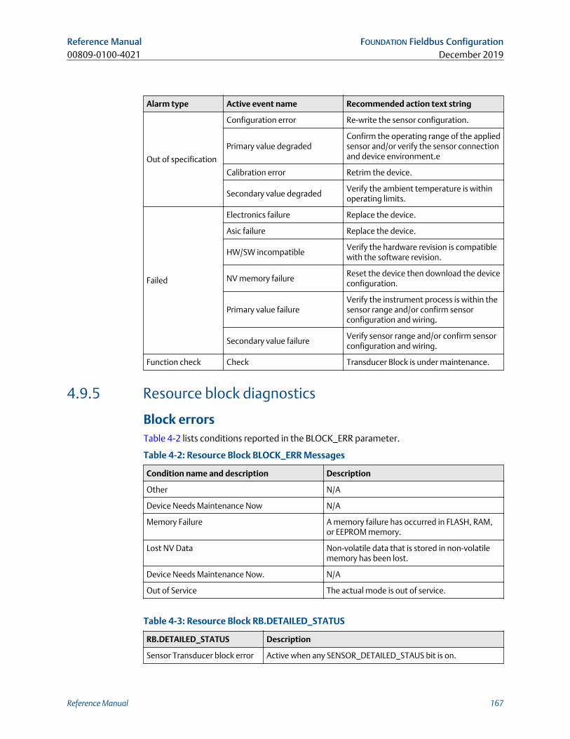
Alarm type Active event name Recommended action text string
Out of specification
Configuration error Re-write the sensor configuration.
Primary value degradedConfirm the operating range of the appliedsensor and/or verify the sensor connectionand device environment.e
Calibration error Retrim the device.
Secondary value degradedVerify the ambient temperature is withinoperating limits.
Failed
Electronics failure Replace the device.
Asic failure Replace the device.
HW/SW incompatibleVerify the hardware revision is compatiblewith the software revision.
NV memory failureReset the device then download the deviceconfiguration.
Primary value failureVerify the instrument process is within thesensor range and/or confirm sensorconfiguration and wiring.
Secondary value failureVerify sensor range and/or confirm sensorconfiguration and wiring.
Function check Check Transducer Block is under maintenance.
4.9.5 Resource block diagnostics
Block errorsTable 4-2 lists conditions reported in the BLOCK_ERR parameter.
Table 4-2: Resource Block BLOCK_ERR Messages
Condition name and description Description
Other N/A
Device Needs Maintenance Now N/A
Memory Failure A memory failure has occurred in FLASH, RAM,or EEPROM memory.
Lost NV Data Non-volatile data that is stored in non-volatilememory has been lost.
Device Needs Maintenance Now. N/A
Out of Service The actual mode is out of service.
Table 4-3: Resource Block RB.DETAILED_STATUS
RB.DETAILED_STATUS Description
Sensor Transducer block error Active when any SENSOR_DETAILED_STAUS bit is on.
Reference Manual FOUNDATION Fieldbus Configuration00809-0100-4021 December 2019
Reference Manual 167
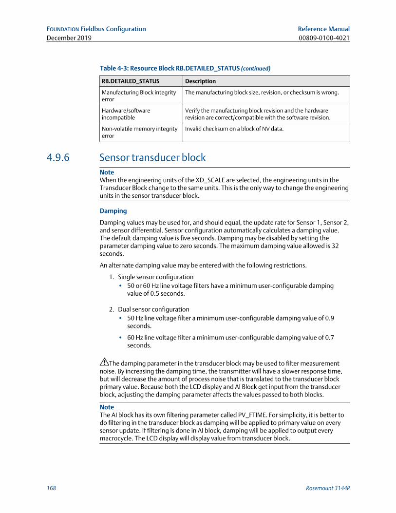
Table 4-3: Resource Block RB.DETAILED_STATUS (continued)
RB.DETAILED_STATUS Description
Manufacturing Block integrityerror
The manufacturing block size, revision, or checksum is wrong.
Hardware/softwareincompatible
Verify the manufacturing block revision and the hardwarerevision are correct/compatible with the software revision.
Non-volatile memory integrityerror
Invalid checksum on a block of NV data.
4.9.6 Sensor transducer blockNoteWhen the engineering units of the XD_SCALE are selected, the engineering units in theTransducer Block change to the same units. This is the only way to change the engineeringunits in the sensor transducer block.
Damping
Damping values may be used for, and should equal, the update rate for Sensor 1, Sensor 2,and sensor differential. Sensor configuration automatically calculates a damping value.The default damping value is five seconds. Damping may be disabled by setting theparameter damping value to zero seconds. The maximum damping value allowed is 32seconds.
An alternate damping value may be entered with the following restrictions.
1. Single sensor configuration• 50 or 60 Hz line voltage filters have a minimum user-configurable damping
value of 0.5 seconds.
2. Dual sensor configuration• 50 Hz line voltage filter a minimum user-configurable damping value of 0.9
seconds.
• 60 Hz line voltage filter a minimum user-configurable damping value of 0.7seconds.
The damping parameter in the transducer block may be used to filter measurementnoise. By increasing the damping time, the transmitter will have a slower response time,but will decrease the amount of process noise that is translated to the transducer blockprimary value. Because both the LCD display and AI Block get input from the transducerblock, adjusting the damping parameter affects the values passed to both blocks.
NoteThe AI block has its own filtering parameter called PV_FTIME. For simplicity, it is better todo filtering in the transducer block as damping will be applied to primary value on everysensor update. If filtering is done in AI block, damping will be applied to output everymacrocycle. The LCD display will display value from transducer block.
FOUNDATION Fieldbus Configuration Reference ManualDecember 2019 00809-0100-4021
168 Rosemount 3144P
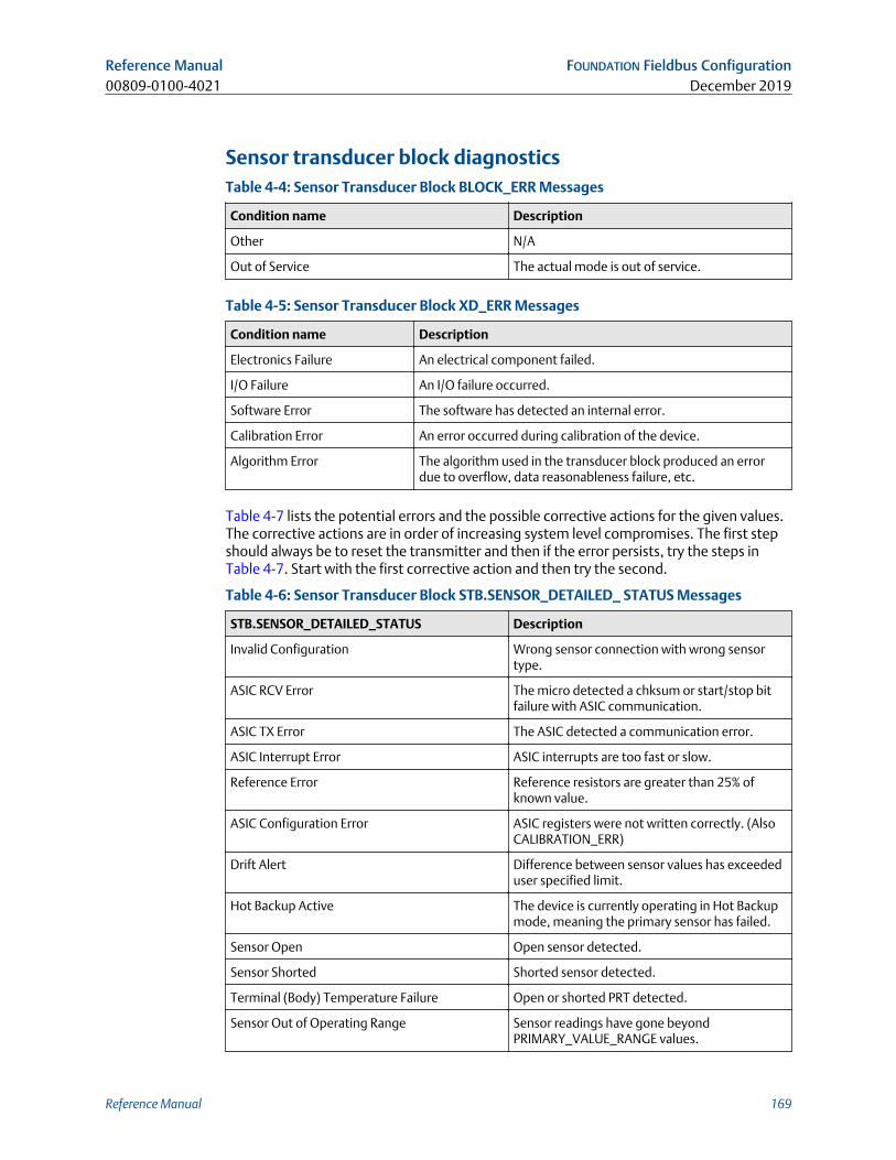
Sensor transducer block diagnosticsTable 4-4: Sensor Transducer Block BLOCK_ERR Messages
Condition name Description
Other N/A
Out of Service The actual mode is out of service.
Table 4-5: Sensor Transducer Block XD_ERR Messages
Condition name Description
Electronics Failure An electrical component failed.
I/O Failure An I/O failure occurred.
Software Error The software has detected an internal error.
Calibration Error An error occurred during calibration of the device.
Algorithm Error The algorithm used in the transducer block produced an errordue to overflow, data reasonableness failure, etc.
Table 4-7 lists the potential errors and the possible corrective actions for the given values.The corrective actions are in order of increasing system level compromises. The first stepshould always be to reset the transmitter and then if the error persists, try the steps inTable 4-7. Start with the first corrective action and then try the second.
Table 4-6: Sensor Transducer Block STB.SENSOR_DETAILED_ STATUS Messages
STB.SENSOR_DETAILED_STATUS Description
Invalid Configuration Wrong sensor connection with wrong sensortype.
ASIC RCV Error The micro detected a chksum or start/stop bitfailure with ASIC communication.
ASIC TX Error The ASIC detected a communication error.
ASIC Interrupt Error ASIC interrupts are too fast or slow.
Reference Error Reference resistors are greater than 25% ofknown value.
ASIC Configuration Error ASIC registers were not written correctly. (AlsoCALIBRATION_ERR)
Drift Alert Difference between sensor values has exceededuser specified limit.
Hot Backup Active The device is currently operating in Hot Backupmode, meaning the primary sensor has failed.
Sensor Open Open sensor detected.
Sensor Shorted Shorted sensor detected.
Terminal (Body) Temperature Failure Open or shorted PRT detected.
Sensor Out of Operating Range Sensor readings have gone beyondPRIMARY_VALUE_RANGE values.
Reference Manual FOUNDATION Fieldbus Configuration00809-0100-4021 December 2019
Reference Manual 169
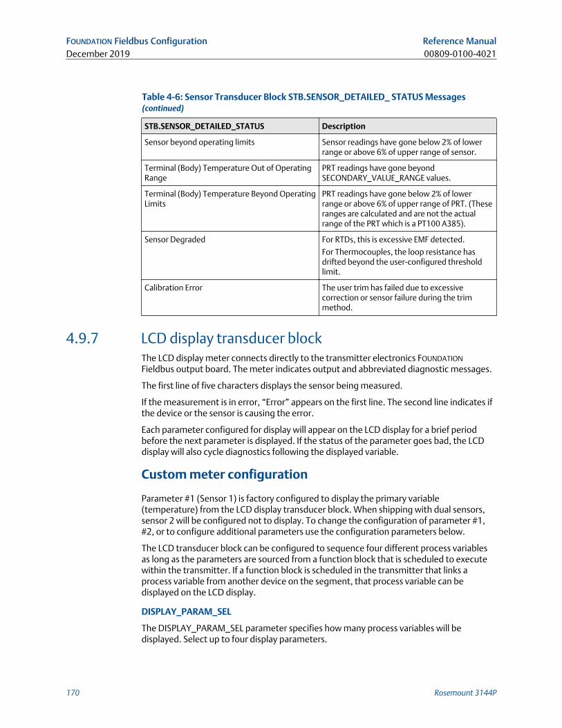
Table 4-6: Sensor Transducer Block STB.SENSOR_DETAILED_ STATUS Messages(continued)
STB.SENSOR_DETAILED_STATUS Description
Sensor beyond operating limits Sensor readings have gone below 2% of lowerrange or above 6% of upper range of sensor.
Terminal (Body) Temperature Out of OperatingRange
PRT readings have gone beyondSECONDARY_VALUE_RANGE values.
Terminal (Body) Temperature Beyond OperatingLimits
PRT readings have gone below 2% of lowerrange or above 6% of upper range of PRT. (Theseranges are calculated and are not the actualrange of the PRT which is a PT100 A385).
Sensor Degraded For RTDs, this is excessive EMF detected.
For Thermocouples, the loop resistance hasdrifted beyond the user-configured thresholdlimit.
Calibration Error The user trim has failed due to excessivecorrection or sensor failure during the trimmethod.
4.9.7 LCD display transducer blockThe LCD display meter connects directly to the transmitter electronics FOUNDATION
Fieldbus output board. The meter indicates output and abbreviated diagnostic messages.
The first line of five characters displays the sensor being measured.
If the measurement is in error, “Error” appears on the first line. The second line indicates ifthe device or the sensor is causing the error.
Each parameter configured for display will appear on the LCD display for a brief periodbefore the next parameter is displayed. If the status of the parameter goes bad, the LCDdisplay will also cycle diagnostics following the displayed variable.
Custom meter configuration
Parameter #1 (Sensor 1) is factory configured to display the primary variable(temperature) from the LCD display transducer block. When shipping with dual sensors,sensor 2 will be configured not to display. To change the configuration of parameter #1,#2, or to configure additional parameters use the configuration parameters below.
The LCD transducer block can be configured to sequence four different process variablesas long as the parameters are sourced from a function block that is scheduled to executewithin the transmitter. If a function block is scheduled in the transmitter that links aprocess variable from another device on the segment, that process variable can bedisplayed on the LCD display.
DISPLAY_PARAM_SEL
The DISPLAY_PARAM_SEL parameter specifies how many process variables will bedisplayed. Select up to four display parameters.
FOUNDATION Fieldbus Configuration Reference ManualDecember 2019 00809-0100-4021
170 Rosemount 3144P
BLK_TAG_#
Note“#” represents the specified parameter number.
Enter the Block Tag of the function block that contains the parameter to be displayed. Thedefault function block tags from the factory are:
TRANSDUCER
AI 1400, 1500, 1600, 1700
PID 1800 and 1900
ISEL 2000
CHAR 2100
ARTH 2200
Output Splitter OSPL 2300
BLK_TYPE_#
Note“#” represents the specified parameter number.
Enter the block type of the function block that contains the parameter to be displayed.This parameter is generally selected via a drop-down menu with a list of possible functionblock type (e.g. Transducer, PID, AI, etc.).
PARAM_INDEX_#
Note“#” represents the specified parameter number.
The PARAM_INDEX_# parameter is generally selected via a dropdown menu with a list ofpossible parameter names based upon what is available in the function block typeselected. Choose the parameter to be displayed.
CUSTOM_TAG_#
Note“#” represents the specified parameter number.
The CUSTOM_TAG_# is an optional user-specified tag identifier that can be configured tobe displayed with the parameter in place of the block tag. Enter a tag of up to fivecharacters.
UNITS_TYPE_#
Note“#” represents the specified parameter number.
The UNITS_TYPE_# parameter is generally selected via a dropdown menu with threeoptions: AUTO, CUSTOM, or NONE. Select AUTO only when the parameter to be displayedis pressure, temperature, or percent. For other parameters, select CUSTOM and be sure toconfigure the CUSTOM_UNITS_# parameter. Select NONE if the parameter is to bedisplayed without associated units.
Reference Manual FOUNDATION Fieldbus Configuration00809-0100-4021 December 2019
Reference Manual 171
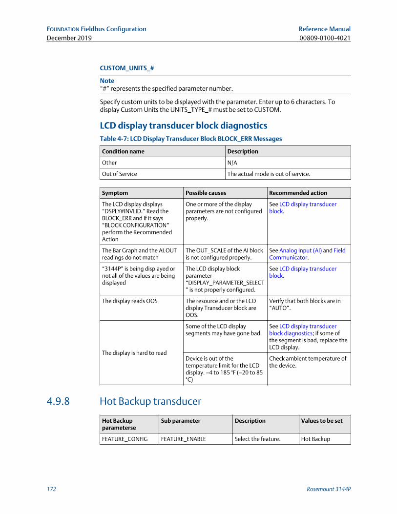
CUSTOM_UNITS_#
Note“#” represents the specified parameter number.
Specify custom units to be displayed with the parameter. Enter up to 6 characters. Todisplay Custom Units the UNITS_TYPE_# must be set to CUSTOM.
LCD display transducer block diagnosticsTable 4-7: LCD Display Transducer Block BLOCK_ERR Messages
Condition name Description
Other N/A
Out of Service The actual mode is out of service.
Symptom Possible causes Recommended action
The LCD display displays“DSPLY#INVLID.” Read theBLOCK_ERR and if it says“BLOCK CONFIGURATION”perform the RecommendedAction
One or more of the displayparameters are not configuredproperly.
See LCD display transducerblock.
The Bar Graph and the AI.OUTreadings do not match
The OUT_SCALE of the AI blockis not configured properly.
See Analog Input (AI) and FieldCommunicator.
“3144P” is being displayed ornot all of the values are beingdisplayed
The LCD display blockparameter“DISPLAY_PARAMETER_SELECT” is not properly configured.
See LCD display transducerblock.
The display reads OOS The resource and or the LCDdisplay Transducer block areOOS.
Verify that both blocks are in“AUTO”.
The display is hard to read
Some of the LCD displaysegments may have gone bad.
See LCD display transducerblock diagnostics; if some ofthe segment is bad, replace theLCD display.
Device is out of thetemperature limit for the LCDdisplay. –4 to 185 °F (–20 to 85°C)
Check ambient temperature ofthe device.
4.9.8 Hot Backup transducer
Hot Backupparameterse
Sub parameter Description Values to be set
FEATURE_CONFIG FEATURE_ENABLE Select the feature. Hot Backup
FOUNDATION Fieldbus Configuration Reference ManualDecember 2019 00809-0100-4021
172 Rosemount 3144P
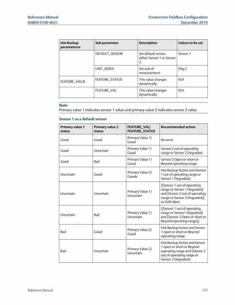
Hot Backupparameterse
Sub parameter Description Values to be set
DEFAULT_SENSOR Set default sensor,either Sensor 1 or Sensor2.
Sensor 1
UNIT_INDEX Set unit ofmeasurement.
Deg C
FEATURE_VALUEFEATURE_STATUS This value changes
dynamically.N/A
FEATURE_VAL This value changesdynamically.
N/A
NotePrimary value 1 indicates sensor 1 value and primary value 2 indicates sensor 2 value.
Sensor 1 as a default sensor
Primary value 1status
Primary value 2status
FEATURE_VAL/FEATURE_STATUS
Recommended action
Good GoodPrimary Value 1/Good
No error
Good UncertainPrimary Value 1/Good
Sensor 2 out of operatingrange or Sensor 2 Degraded.
Good BadPrimary Value 1/Good
Sensor 2 Open or short orBeyond operating range.
Uncertain GoodPrimary Value 2/Goode
Hot Backup Active and (Sensor1 out of operating range orSensor 1 Degraded).
Uncertain UncertainPrimary Value 1/Uncertain
([Sensor 1 out of operatingrange or Sensor 1 Degraded]and [Sensor 2 out of operatingrange or Sensor 2 Degraded])or Drift Alert.
Uncertain BadPrimary Value 1/Uncertain
([Sensor 1 out of operatingrange or Sensor1 Degraded]and [Sensor 2 Open or short orBeyond operating range]).
Bad GoodPrimary Value 2/Good
Hot Backup Active and Sensor1 open or short or Beyondoperating range.
Bad UncertainPrimary Value 2/Uncertain
Hot Backup Active and Sensor1 open or short or Beyondoperating range and (Sensor 2out of operating range orSensor 2 Degraded).
Reference Manual FOUNDATION Fieldbus Configuration00809-0100-4021 December 2019
Reference Manual 173
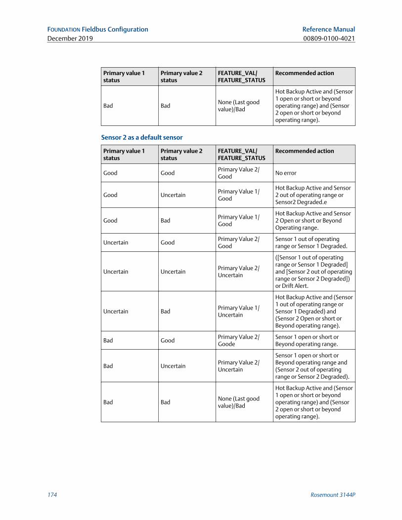
Primary value 1status
Primary value 2status
FEATURE_VAL/FEATURE_STATUS
Recommended action
Bad BadNone (Last goodvalue)/Bad
Hot Backup Active and (Sensor1 open or short or beyondoperating range) and (Sensor2 open or short or beyondoperating range).
Sensor 2 as a default sensor
Primary value 1status
Primary value 2status
FEATURE_VAL/FEATURE_STATUS
Recommended action
Good GoodPrimary Value 2/Good
No error
Good UncertainPrimary Value 1/Good
Hot Backup Active and Sensor2 out of operating range orSensor2 Degraded.e
Good BadPrimary Value 1/Good
Hot Backup Active and Sensor2 Open or short or BeyondOperating range.
Uncertain GoodPrimary Value 2/Good
Sensor 1 out of operatingrange or Sensor 1 Degraded.
Uncertain UncertainPrimary Value 2/Uncertain
([Sensor 1 out of operatingrange or Sensor 1 Degraded]and [Sensor 2 out of operatingrange or Sensor 2 Degraded])or Drift Alert.
Uncertain BadPrimary Value 1/Uncertain
Hot Backup Active and (Sensor1 out of operating range orSensor 1 Degraded) and(Sensor 2 Open or short orBeyond operating range).
Bad GoodPrimary Value 2/Goode
Sensor 1 open or short orBeyond operating range.
Bad UncertainPrimary Value 2/Uncertain
Sensor 1 open or short orBeyond operating range and(Sensor 2 out of operatingrange or Sensor 2 Degraded).
Bad BadNone (Last goodvalue)/Bad
Hot Backup Active and (Sensor1 open or short or beyondoperating range) and (Sensor2 open or short or beyondoperating range).
FOUNDATION Fieldbus Configuration Reference ManualDecember 2019 00809-0100-4021
174 Rosemount 3144P
4.10 Analog Input (AI)
4.10.1 SimulationSimulate replaces the channel value coming from the sensor transducer block. For testingpurposes, it is possible to manually drive the output of the analog input block to a desiredvalue. There are two ways to do this.
Manual mode
To change only the OUT_VALUE and not the OUT_STATUS of the AI Block, place theTARGET MODE of the block to MANUAL. Then, change the OUT_VALUE to the desiredvalue.
Simulate
Procedure
1. If the SIMULATE switch is in the OFF position, move it to the ON position. If theSIMULATE jumper is already in the ON position, you must move it to off and place itback in the ON position.
NoteAs a safety measure, the switch must be reset every time power is interrupted tothe device in order to enable SIMULATE. This prevents a device that is tested on thebench from getting installed in the process with SIMULATE still active.
2. To change both the OUT_VALUE and OUT_STATUS of the AI Block, set the TARGETMODE to AUTO.
3. Set SIMULATE_ENABLE_DISABLE to ‘Active.’
4. Enter the desired SIMULATE_VALUE to change the OUT_VALUE andSIMULATE_STATUS_QUALITY to change the OUT_STATUS. If errors occur whenperforming the above steps, be sure that the SIMULATE jumper has been reset afterpowering up the device.
4.10.2 Configure the AI block A minimum of four parameters are required to configure the AI block. The parameters
are described below, with example configurations shown at the end of this section.
CHANNEL
Select the channel that corresponds to the desired sensor measurement .
Channel Measurement
1 Input 1
2 Input 2
3 Differential
4 Terminal (body) temperature
Reference Manual FOUNDATION Fieldbus Configuration00809-0100-4021 December 2019
Reference Manual 175
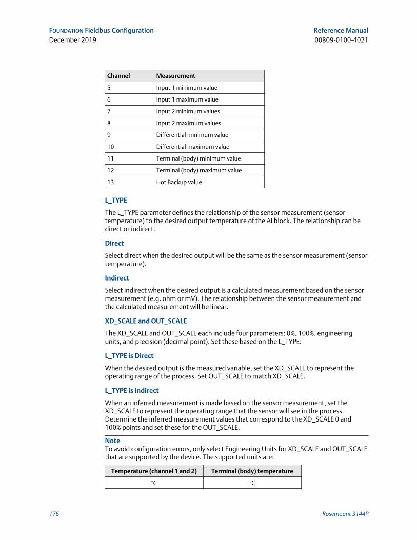
Channel Measurement
5 Input 1 minimum value
6 Input 1 maximum value
7 Input 2 minimum values
8 Input 2 maximum values
9 Differential minimum value
10 Differential maximum value
11 Terminal (body) minimum value
12 Terminal (body) maximum value
13 Hot Backup value
L_TYPE
The L_TYPE parameter defines the relationship of the sensor measurement (sensortemperature) to the desired output temperature of the AI block. The relationship can bedirect or indirect.
Direct
Select direct when the desired output will be the same as the sensor measurement (sensortemperature).
Indirect
Select indirect when the desired output is a calculated measurement based on the sensormeasurement (e.g. ohm or mV). The relationship between the sensor measurement andthe calculated measurement will be linear.
XD_SCALE and OUT_SCALE
The XD_SCALE and OUT_SCALE each include four parameters: 0%, 100%, engineeringunits, and precision (decimal point). Set these based on the L_TYPE:
L_TYPE is Direct
When the desired output is the measured variable, set the XD_SCALE to represent theoperating range of the process. Set OUT_SCALE to match XD_SCALE.
L_TYPE is Indirect
When an inferred measurement is made based on the sensor measurement, set theXD_SCALE to represent the operating range that the sensor will see in the process.Determine the inferred measurement values that correspond to the XD_SCALE 0 and100% points and set these for the OUT_SCALE.
NoteTo avoid configuration errors, only select Engineering Units for XD_SCALE and OUT_SCALEthat are supported by the device. The supported units are:
Temperature (channel 1 and 2) Terminal (body) temperature
°C °C
FOUNDATION Fieldbus Configuration Reference ManualDecember 2019 00809-0100-4021
176 Rosemount 3144P
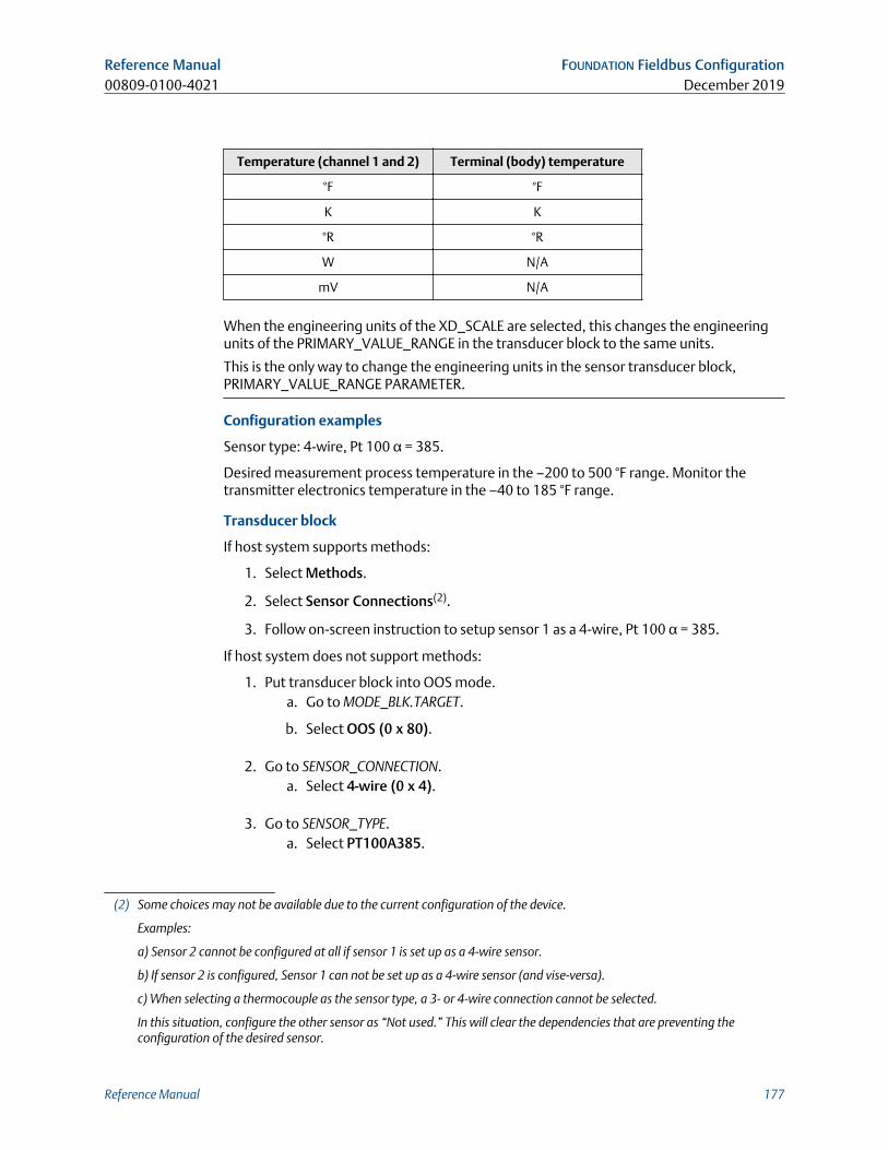
Temperature (channel 1 and 2) Terminal (body) temperature
°F °F
K K
°R °R
W N/A
mV N/A
When the engineering units of the XD_SCALE are selected, this changes the engineeringunits of the PRIMARY_VALUE_RANGE in the transducer block to the same units.
This is the only way to change the engineering units in the sensor transducer block,PRIMARY_VALUE_RANGE PARAMETER.
Configuration examples
Sensor type: 4-wire, Pt 100 α = 385.
Desired measurement process temperature in the –200 to 500 °F range. Monitor thetransmitter electronics temperature in the –40 to 185 °F range.
Transducer block
If host system supports methods:
1. Select Methods.
2. Select Sensor Connections(2).
3. Follow on-screen instruction to setup sensor 1 as a 4-wire, Pt 100 α = 385.
If host system does not support methods:
1. Put transducer block into OOS mode.a. Go to MODE_BLK.TARGET.
b. Select OOS (0 x 80).
2. Go to SENSOR_CONNECTION.a. Select 4-wire (0 x 4).
3. Go to SENSOR_TYPE.a. Select PT100A385.
(2) Some choices may not be available due to the current configuration of the device.
Examples:
a) Sensor 2 cannot be configured at all if sensor 1 is set up as a 4-wire sensor.
b) If sensor 2 is configured, Sensor 1 can not be set up as a 4-wire sensor (and vise-versa).
c) When selecting a thermocouple as the sensor type, a 3- or 4-wire connection cannot be selected.
In this situation, configure the other sensor as “Not used.” This will clear the dependencies that are preventing theconfiguration of the desired sensor.
Reference Manual FOUNDATION Fieldbus Configuration00809-0100-4021 December 2019
Reference Manual 177
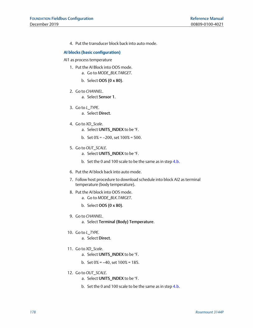
4. Put the transducer block back into auto mode.
AI blocks (basic configuration)
AI1 as process temperature
1. Put the AI Block into OOS mode.a. Go to MODE_BLK.TARGET.
b. Select OOS (0 x 80).
2. Go to CHANNEL.a. Select Sensor 1.
3. Go to L_TYPE.a. Select Direct.
4. Go to XD_Scale.a. Select UNITS_INDEX to be °F.
b. Set 0% = –200, set 100% = 500.
5. Go to OUT_SCALE.a. Select UNITS_INDEX to be °F.
b. Set the 0 and 100 scale to be the same as in step 4.b.
6. Put the AI block back into auto mode.
7. Follow host procedure to download schedule into block AI2 as terminaltemperature (body temperature).
8. Put the AI block into OOS mode.a. Go to MODE_BLK.TARGET.
b. Select OOS (0 x 80).
9. Go to CHANNEL.a. Select Terminal (Body) Temperature.
10. Go to L_TYPE.a. Select Direct.
11. Go to XD_Scale.a. Select UNITS_INDEX to be °F.
b. Set 0% = –40, set 100% = 185.
12. Go to OUT_SCALE.a. Select UNITS_INDEX to be °F.
b. Set the 0 and 100 scale to be the same as in step 4.b.
FOUNDATION Fieldbus Configuration Reference ManualDecember 2019 00809-0100-4021
178 Rosemount 3144P
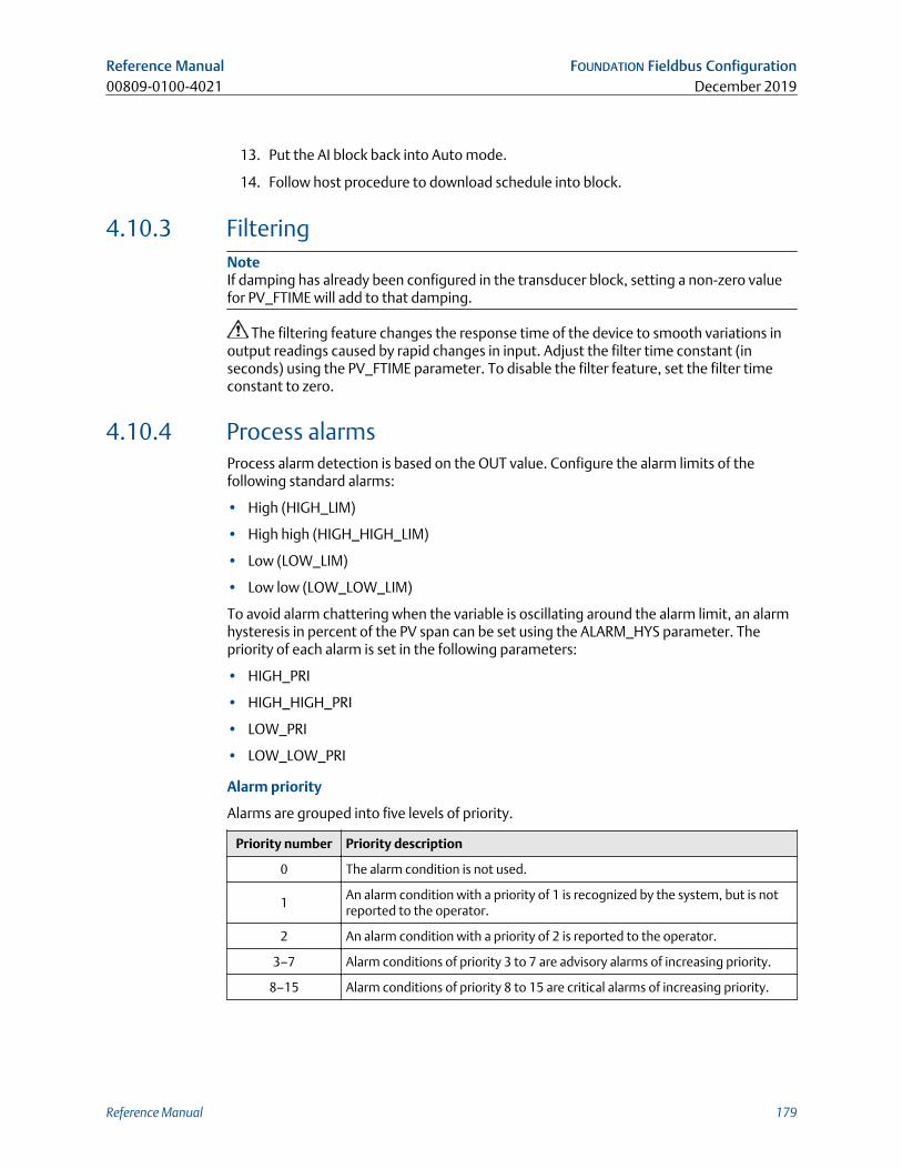
13. Put the AI block back into Auto mode.
14. Follow host procedure to download schedule into block.
4.10.3 FilteringNoteIf damping has already been configured in the transducer block, setting a non-zero valuefor PV_FTIME will add to that damping.
The filtering feature changes the response time of the device to smooth variations inoutput readings caused by rapid changes in input. Adjust the filter time constant (inseconds) using the PV_FTIME parameter. To disable the filter feature, set the filter timeconstant to zero.
4.10.4 Process alarmsProcess alarm detection is based on the OUT value. Configure the alarm limits of thefollowing standard alarms:
• High (HIGH_LIM)
• High high (HIGH_HIGH_LIM)
• Low (LOW_LIM)
• Low low (LOW_LOW_LIM)
To avoid alarm chattering when the variable is oscillating around the alarm limit, an alarmhysteresis in percent of the PV span can be set using the ALARM_HYS parameter. Thepriority of each alarm is set in the following parameters:
• HIGH_PRI
• HIGH_HIGH_PRI
• LOW_PRI
• LOW_LOW_PRI
Alarm priority
Alarms are grouped into five levels of priority.
Priority number Priority description
0 The alarm condition is not used.
1An alarm condition with a priority of 1 is recognized by the system, but is notreported to the operator.
2 An alarm condition with a priority of 2 is reported to the operator.
3–7 Alarm conditions of priority 3 to 7 are advisory alarms of increasing priority.
8–15 Alarm conditions of priority 8 to 15 are critical alarms of increasing priority.
Reference Manual FOUNDATION Fieldbus Configuration00809-0100-4021 December 2019
Reference Manual 179
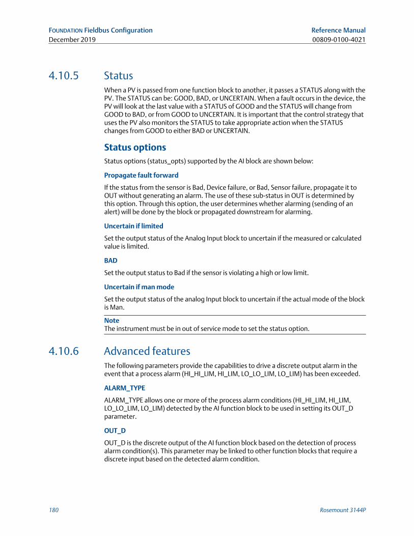
4.10.5 StatusWhen a PV is passed from one function block to another, it passes a STATUS along with thePV. The STATUS can be: GOOD, BAD, or UNCERTAIN. When a fault occurs in the device, thePV will look at the last value with a STATUS of GOOD and the STATUS will change fromGOOD to BAD, or from GOOD to UNCERTAIN. It is important that the control strategy thatuses the PV also monitors the STATUS to take appropriate action when the STATUSchanges from GOOD to either BAD or UNCERTAIN.
Status optionsStatus options (status_opts) supported by the AI block are shown below:
Propagate fault forward
If the status from the sensor is Bad, Device failure, or Bad, Sensor failure, propagate it toOUT without generating an alarm. The use of these sub-status in OUT is determined bythis option. Through this option, the user determines whether alarming (sending of analert) will be done by the block or propagated downstream for alarming.
Uncertain if limited
Set the output status of the Analog Input block to uncertain if the measured or calculatedvalue is limited.
BAD
Set the output status to Bad if the sensor is violating a high or low limit.
Uncertain if man mode
Set the output status of the analog Input block to uncertain if the actual mode of the blockis Man.
NoteThe instrument must be in out of service mode to set the status option.
4.10.6 Advanced featuresThe following parameters provide the capabilities to drive a discrete output alarm in theevent that a process alarm (HI_HI_LIM, HI_LIM, LO_LO_LIM, LO_LIM) has been exceeded.
ALARM_TYPE
ALARM_TYPE allows one or more of the process alarm conditions (HI_HI_LIM, HI_LIM,LO_LO_LIM, LO_LIM) detected by the AI function block to be used in setting its OUT_Dparameter.
OUT_D
OUT_D is the discrete output of the AI function block based on the detection of processalarm condition(s). This parameter may be linked to other function blocks that require adiscrete input based on the detected alarm condition.
FOUNDATION Fieldbus Configuration Reference ManualDecember 2019 00809-0100-4021
180 Rosemount 3144P
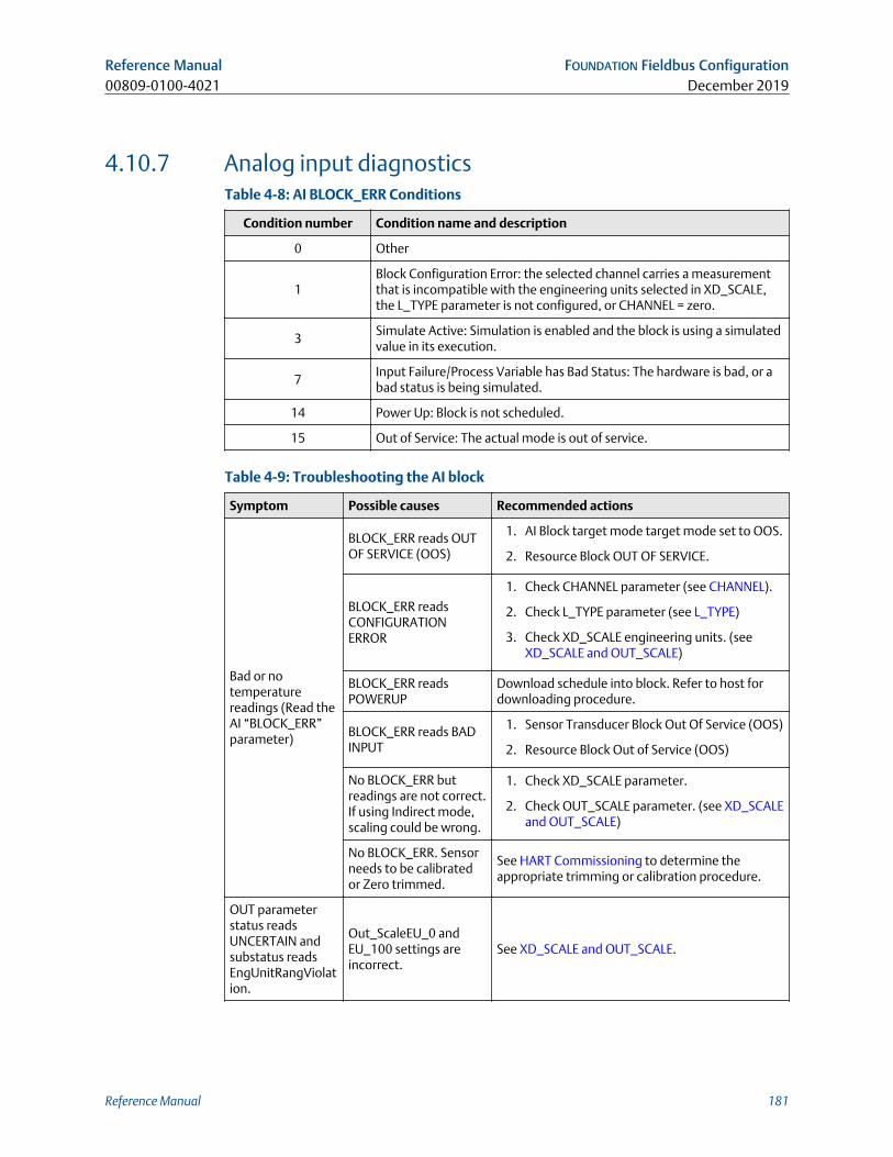
4.10.7 Analog input diagnosticsTable 4-8: AI BLOCK_ERR Conditions
Condition number Condition name and description
0 Other
1Block Configuration Error: the selected channel carries a measurementthat is incompatible with the engineering units selected in XD_SCALE,the L_TYPE parameter is not configured, or CHANNEL = zero.
3Simulate Active: Simulation is enabled and the block is using a simulatedvalue in its execution.
7Input Failure/Process Variable has Bad Status: The hardware is bad, or abad status is being simulated.
14 Power Up: Block is not scheduled.
15 Out of Service: The actual mode is out of service.
Table 4-9: Troubleshooting the AI block
Symptom Possible causes Recommended actions
Bad or notemperaturereadings (Read theAI “BLOCK_ERR”parameter)
BLOCK_ERR reads OUTOF SERVICE (OOS)
1. AI Block target mode target mode set to OOS.
2. Resource Block OUT OF SERVICE.
BLOCK_ERR readsCONFIGURATIONERROR
1. Check CHANNEL parameter (see CHANNEL).
2. Check L_TYPE parameter (see L_TYPE)
3. Check XD_SCALE engineering units. (seeXD_SCALE and OUT_SCALE)
BLOCK_ERR readsPOWERUP
Download schedule into block. Refer to host fordownloading procedure.
BLOCK_ERR reads BADINPUT
1. Sensor Transducer Block Out Of Service (OOS)
2. Resource Block Out of Service (OOS)
No BLOCK_ERR butreadings are not correct.If using Indirect mode,scaling could be wrong.
1. Check XD_SCALE parameter.
2. Check OUT_SCALE parameter. (see XD_SCALEand OUT_SCALE)
No BLOCK_ERR. Sensorneeds to be calibratedor Zero trimmed.
See HART Commissioning to determine theappropriate trimming or calibration procedure.
OUT parameterstatus readsUNCERTAIN andsubstatus readsEngUnitRangViolation.
Out_ScaleEU_0 andEU_100 settings areincorrect.
See XD_SCALE and OUT_SCALE.
Reference Manual FOUNDATION Fieldbus Configuration00809-0100-4021 December 2019
Reference Manual 181
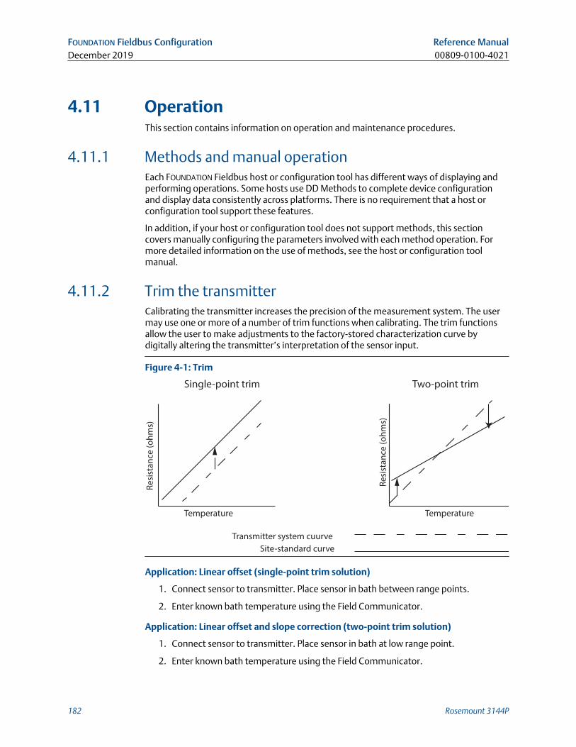
4.11 OperationThis section contains information on operation and maintenance procedures.
4.11.1 Methods and manual operationEach FOUNDATION Fieldbus host or configuration tool has different ways of displaying andperforming operations. Some hosts use DD Methods to complete device configurationand display data consistently across platforms. There is no requirement that a host orconfiguration tool support these features.
In addition, if your host or configuration tool does not support methods, this sectioncovers manually configuring the parameters involved with each method operation. Formore detailed information on the use of methods, see the host or configuration toolmanual.
4.11.2 Trim the transmitterCalibrating the transmitter increases the precision of the measurement system. The usermay use one or more of a number of trim functions when calibrating. The trim functionsallow the user to make adjustments to the factory-stored characterization curve bydigitally altering the transmitter’s interpretation of the sensor input.
Figure 4-1: Trim
Transmitter system cuurve
Site-standard curve
Re
sist
an
ce (
oh
ms)
Re
sist
an
ce (
oh
ms)
Temperature Temperature
Single-point trim Two-point trim
Application: Linear offset (single-point trim solution)
1. Connect sensor to transmitter. Place sensor in bath between range points.
2. Enter known bath temperature using the Field Communicator.
Application: Linear offset and slope correction (two-point trim solution)
1. Connect sensor to transmitter. Place sensor in bath at low range point.
2. Enter known bath temperature using the Field Communicator.
FOUNDATION Fieldbus Configuration Reference ManualDecember 2019 00809-0100-4021
182 Rosemount 3144P
3. Repeat at high range point.
Sensor calibration, lower and upper trim methodsIn order to calibrate the transmitter, run the lower and upper trim methods. If your systemdoes not support methods, manually configure the transducer block parameters listedbelow.
Procedure
1. Set MODE_BLK.TARGET_X to OOS.
2. Set SENSOR_CAL_METHOD_X to User Trim.
3. Set CAL_UNIT_X to supported engineering units in the transducer block.
4. Apply temperature that corresponds to the lower calibration point and allow thetemperature to stabilize. The temperature must be between the range limitsdefined in PRIMRY_VALUE_RANGE_X.
5. Set values of CAL_POINT_LO_X to correspond to the temperature applied by thesensor.
6. Apply temperature, temperature corresponding to the upper calibration.
7. Allow temperature to stabilize.
8. Set CAL_POINT_HI_X.
NoteCAL_POINT_HI_X must be within PRIMARY_VALUE_RANGE_X and greater thanCAL_POINT_LO_X + CAL_MIN_SPAN_X.
9. Set SENSOR_CAL_DATE_X to the current date.
10. Set SENSOR_CAL_WHO_X to the person responsible for the calibration.
11. Set SENSOR _CAL_LOC_X to the calibration location.
12. Set MODE_BLK.TARGET_X to AUTO.
If trim fails the transmitter will automatically revert to factory trim. Excessivecorrection or sensor failure could cause device status to read “calibration error.” Toclear this, trim the transmitter.
Recall factory trimTo recall a factory trim on the transmitter, run the Recall Factory Trim.
NoteWhen sensor type is changed, the transmitter reverts to the factory trim. Changing sensortype causes you to loose any trim performed on the transmitter.
If your system does not support methods, manually configure the Transducer Blockparameters.
Procedure
1. Set TARGET_MODE to OOS
2. Set SENSOR_CAL_METHOD to Factory Trim.
3. Set SENSOR_CAL_DATE to the current date.
Reference Manual FOUNDATION Fieldbus Configuration00809-0100-4021 December 2019
Reference Manual 183
4. Set SENSOR_CAL_WHO to the person responsible for the calibration.
5. Set SENSOR _CAL_LOC to the calibration location.
6. Set TARGET_MODE to AUTO.
4.11.3 Advanced diagnostics
Thermocouple degradation diagnosticThermocouple degradation diagnostic acts as a gauge of general thermocouple healthand is indicative of any major changes in the status of the thermocouple or thethermocouple loop. The transmitter monitors for increasing resistance of thethermocouple loop to detect drift conditions or wiring condition changes. The degradingthermocouple can be caused by wire thinning, sensor breakdown, moisture intrusion orcorrosion and can be an indication of an eventual sensor failure.
How itworks:
The thermocouple degradation diagnostic measures the amount of resistanceon a thermocouple sensor path. Ideally a thermocouple would have zeroresistance, but in reality it has some resistance especially for longthermocouple extension wires. As the sensor loop degrades (including sensordegradation and wire or junctions degradation), the resistance of the loopincreases. First, the transmitter is configured to a baseline by the user. Then, atleast once per second, the degradation diagnostic monitors the resistance inthe loop by sending a pulsed current (in microamps) on the loop, measuringthe voltage induced and calculating the effective resistance. As the resistanceincreases, the diagnostic can detect when the resistance exceeds the thresholdset by the user at which the diagnostic will provide a digital alert. This feature isnot intended to be a precise measurement of thermocouple status, but is ageneral indicator of thermocouple and thermocouple loop health by providingtrending over time.
The thermocouple degradation diagnostic does not detect shorted thermocoupleconditions.
Thermocouple diagnostic must be connected, configured, and enabled to read athermocouple. Once the diagnostic has been activated, a Baseline resistance value iscalculated. Then a threshold Trigger must be selected, which can be two, three, or fourtimes the Baseline resistance, or the default of 5000 ohms. If the thermocouple loopresistance reaches the trigger level, a maintenance alert is generated.
ImportantThe thermocouple degradation diagnostic monitors the health of the entire thermocoupleloop, including wiring, terminations, junctions, and the sensor itself. Therefore, it isimperative that the diagnostic baseline resistance be measured with the sensor fullyinstalled and wired in the process, and not on the bench.
NoteThe thermocouple resistance algorithm does not calculate resistance values while theactive calibrator mode is enabled.
FOUNDATION Fieldbus Configuration Reference ManualDecember 2019 00809-0100-4021
184 Rosemount 3144P
Table 4-10: AMS Device Manager terms
Term Definition
Trigger level
Threshold resistance value for the thermocouple loop. The Trigger Levelmay be set for 2, 3, or 4 3 Baseline or the default of 5000 Ohms. If theresistance of the thermocouple loop surpasses the trigger level, aPlantweb maintenance alert will be generated.
Resistance This is the existing resistance reading of the thermocouple loop.
Baseline valueThe resistance of the thermocouple loop obtained after installation, orafter resetting the Baseline value. The Trigger Level may be calculatedfrom the baseline value.
Trigger setting May be set for 2, 3, or 4 3 baseline or the default of 5000 ohms.
Sensor 1 degraded
A Plantweb maintenance alert generated when the thermocoupledegradation diagnostic is enabled and the resistance in the loop exceedsthe user-configured trigger level. This alert indicates maintenance maybe necessary or that the thermocouple may have degraded.
ConfigureLaunches a method so the user can enable or disable the thermocoupledegradation diagnostic, select the trigger level, and automaticallycalculates the baseline value (which may take several seconds).
Reset baseline valueLaunches a method to recalculate the baseline value (which may takeseveral seconds).
EnabledIndicates when the thermocouple degradation diagnostic is enabled forthe sensor.
Learning Indicates when checked that the baseline value is being calculated.
LicensedThe check box indicates if thermocouple degradation diagnostic isavailable for the specific transmitter.
Minimum and maximum temperature trackingMinimum and maximum temperature tracking (Min/Max Tracking) when enabled, recordsminimum and maximum temperatures with date and time stamps on Rosemount 3144PTemperature Transmitters. This feature records values for Sensor 1, Sensor 2, differentialand terminal (body) temperatures. Min/Max Tracking only records temperature maximaand minima obtained since the last reset, and is not a logging function.
To track maximum and minimum temperatures, Min/Max Tracking must be enabled in thetransducer function block using a Field Communicator, AMS Device Manager, or othercommunicator. While enabled, this feature allows for a reset of information at any time,and all variables can be reset simultaneously. Additionally, sensor 1, sensor 2, differential,and terminal (body) temperature minimum and maximum values may be resetindividually. Once a particular field has been reset, the previous values are overwritten.
4.11.4 Statistical process monitoring (SPM)SPM algorithm provides basic information regarding the behavior of processmeasurements such as PID control block and actual valve position. The algorithm canmonitor up to four user selected variables. All variables must reside in a scheduledfunction block contained in the device. This algorithm can perform higher levels of
Reference Manual FOUNDATION Fieldbus Configuration00809-0100-4021 December 2019
Reference Manual 185
diagnostics by distribution of computational power to field devices. The two statisticalparameters monitored by the SPM are mean and standard deviation. By using the meanand standard deviation, the process or control levels and dynamics can be monitored forchange over time. The algorithm also provides:
• Configurable limits/alarms for high variation, low dynamics, and mean changes withrespect to the learned levels
• Necessary statistical information for regulatory control loop diagnostics, root causediagnostics, and operations diagnostics
NoteFOUNDATION Fieldbus devices offer a wealth of information to the user. Both processmeasurement and control is feasible at the device level. The devices contain both theprocess measurements and control signals that are necessary to not only control theprocess, but to determine if the process and control is healthy. By looking at the processmeasurement data and control output over time, additional insight into the process canbe gained. Under some load conditions and process demands, changes could beinterpreted as degradation of instruments, valves, or major components such as pumps,compressors, heat exchangers, etc. This degradation may indicate that the loop controlscheme should be re-tuned or re-evaluated. By learning a healthy process and continuallycomparing current information to the known healthy information, problems fromdegradation and eventual failure can be remedied ahead of time. These diagnostics aid inthe engineering and maintenance of the devices. False alarms and missed detections mayoccur. If a reoccurring problem in the process exists, contact Emerson for assistance.
Configuration phaseThe configuration phase is an inactive state when the SPM algorithm can be configured. Inthis phase, the block tags, block type, parameter, limits for high variation, low dynamics,and mean change detection can be set by the user. The “Statistical Process MonitoringActivation” parameter must be set to “disabled” to configure any SPM parameter. SPM canmonitor any linkable input or output parameter of a scheduled function block that residesin the device.
Learning phaseIn the learning phase of SPM, the algorithm establishes a baseline of the mean anddynamics of a SPM variable. The baseline data is compared to current data for calculatingany changes in mean or dynamics of the SPM variables.
Monitoring phaseThe monitoring phase starts once the learning process is complete. The algorithmcompares the current values to the baseline values of the mean and standard deviation.
FOUNDATION Fieldbus Configuration Reference ManualDecember 2019 00809-0100-4021
186 Rosemount 3144P
During this phase the algorithm computes the percent change in mean and standarddeviation to determine if the defined limits are violated.
4.11.5 SPM configurationSPM_Bypass_Verification
“Yes” means that the verification of the baseline is turned off while “No” indicates thelearned baseline is compared to the next current calculated value to ensure a goodbaseline value. The recommended value is NO.
SPM_Monitoring_Cycle
SPM_Monitoring_Cycle is the length of time the process values are taken and used in eachcalculation. A longer monitoring cycle may provide a more stable mean value with thedefault set at 15 minutes.
SPM#_Block_Tag
Enter the Block Tag of the function block containing the parameter to be monitored. Blocktag must be entered, since there is no pull-down menu to select the tag. The tag must be avalid “Block Tag” in the device. The default block tags from the factory are:
• AI 1400
• AI 1500
• PID 1600
• ISEL 1700
• CHAR 1800
• ARITH 1900
SPM can also monitor “out” parameters from other devices. Link the “out” parameter toan input parameter of a function block residing in the device, and set up SPM to monitorthe input parameter.
SPM#_Block Type
Enter the Block Type of the function block containing the parameter to be monitored.
SPM#_Parameter Index
Enter the Parameter Index of the parameter to be monitored.
SPM#_Thresholds
The SPM#_Thresholds allow alerts to be sent when the values are beyond the thresholdvalues that set for each parameter.
Mean limit
Alert Limit value in percent change of the Mean compared with the baseline mean value.
High variation
Alert Limit value in percent change of the Stdev compared with the baseline Stdev value.
Reference Manual FOUNDATION Fieldbus Configuration00809-0100-4021 December 2019
Reference Manual 187
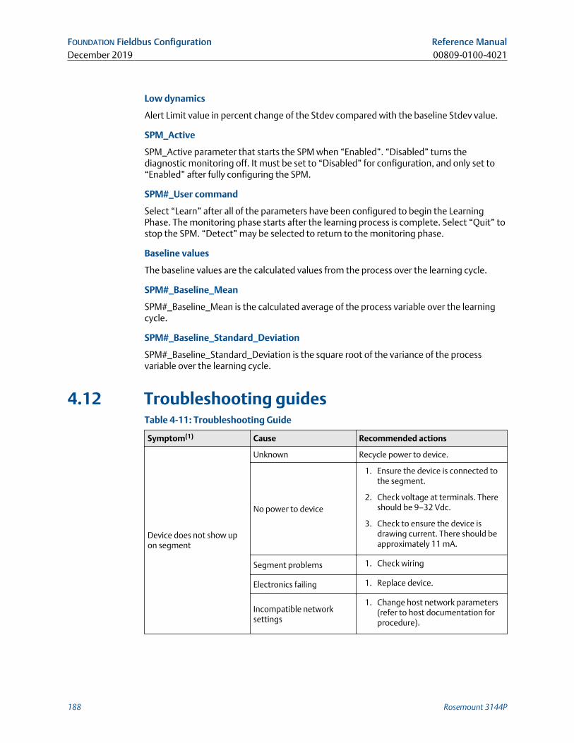
Low dynamics
Alert Limit value in percent change of the Stdev compared with the baseline Stdev value.
SPM_Active
SPM_Active parameter that starts the SPM when “Enabled”. “Disabled” turns thediagnostic monitoring off. It must be set to “Disabled” for configuration, and only set to“Enabled” after fully configuring the SPM.
SPM#_User command
Select “Learn” after all of the parameters have been configured to begin the LearningPhase. The monitoring phase starts after the learning process is complete. Select “Quit” tostop the SPM. “Detect” may be selected to return to the monitoring phase.
Baseline values
The baseline values are the calculated values from the process over the learning cycle.
SPM#_Baseline_Mean
SPM#_Baseline_Mean is the calculated average of the process variable over the learningcycle.
SPM#_Baseline_Standard_Deviation
SPM#_Baseline_Standard_Deviation is the square root of the variance of the processvariable over the learning cycle.
4.12 Troubleshooting guidesTable 4-11: Troubleshooting Guide
Symptom(1) Cause Recommended actions
Device does not show upon segment
Unknown Recycle power to device.
No power to device
1. Ensure the device is connected tothe segment.
2. Check voltage at terminals. Thereshould be 9–32 Vdc.
3. Check to ensure the device isdrawing current. There should beapproximately 11 mA.
Segment problems 1. Check wiring
Electronics failing 1. Replace device.
Incompatible networksettings
1. Change host network parameters(refer to host documentation forprocedure).
FOUNDATION Fieldbus Configuration Reference ManualDecember 2019 00809-0100-4021
188 Rosemount 3144P
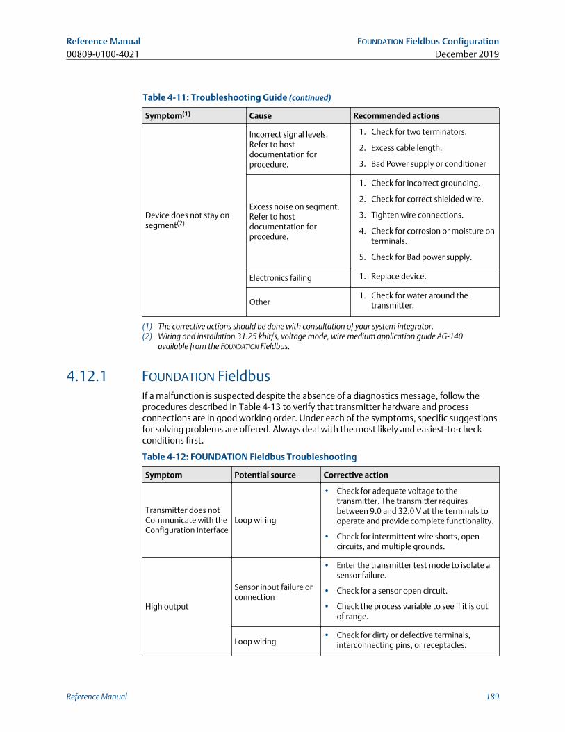
Table 4-11: Troubleshooting Guide (continued)
Symptom(1) Cause Recommended actions
Device does not stay onsegment(2)
Incorrect signal levels.Refer to hostdocumentation forprocedure.
1. Check for two terminators.
2. Excess cable length.
3. Bad Power supply or conditioner
Excess noise on segment.Refer to hostdocumentation forprocedure.
1. Check for incorrect grounding.
2. Check for correct shielded wire.
3. Tighten wire connections.
4. Check for corrosion or moisture onterminals.
5. Check for Bad power supply.
Electronics failing 1. Replace device.
Other1. Check for water around the
transmitter.
(1) The corrective actions should be done with consultation of your system integrator.(2) Wiring and installation 31.25 kbit/s, voltage mode, wire medium application guide AG-140
available from the FOUNDATION Fieldbus.
4.12.1 FOUNDATION FieldbusIf a malfunction is suspected despite the absence of a diagnostics message, follow theprocedures described in Table 4-13 to verify that transmitter hardware and processconnections are in good working order. Under each of the symptoms, specific suggestionsfor solving problems are offered. Always deal with the most likely and easiest-to-checkconditions first.
Table 4-12: FOUNDATION Fieldbus Troubleshooting
Symptom Potential source Corrective action
Transmitter does notCommunicate with theConfiguration Interface
Loop wiring
• Check for adequate voltage to thetransmitter. The transmitter requiresbetween 9.0 and 32.0 V at the terminals tooperate and provide complete functionality.
• Check for intermittent wire shorts, opencircuits, and multiple grounds.
High output
Sensor input failure orconnection
• Enter the transmitter test mode to isolate asensor failure.
• Check for a sensor open circuit.
• Check the process variable to see if it is outof range.
Loop wiring• Check for dirty or defective terminals,
interconnecting pins, or receptacles.
Reference Manual FOUNDATION Fieldbus Configuration00809-0100-4021 December 2019
Reference Manual 189
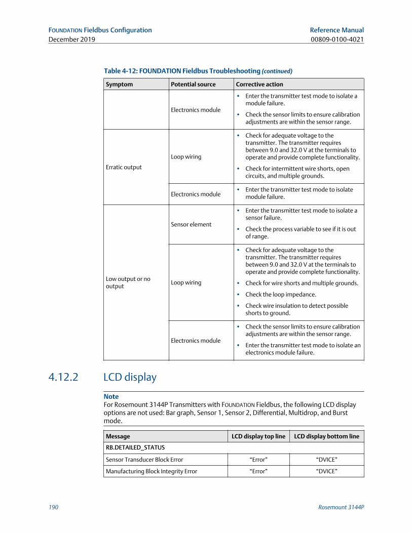
Table 4-12: FOUNDATION Fieldbus Troubleshooting (continued)
Symptom Potential source Corrective action
Electronics module
• Enter the transmitter test mode to isolate amodule failure.
• Check the sensor limits to ensure calibrationadjustments are within the sensor range.
Erratic output
Loop wiring
• Check for adequate voltage to thetransmitter. The transmitter requiresbetween 9.0 and 32.0 V at the terminals tooperate and provide complete functionality.
• Check for intermittent wire shorts, opencircuits, and multiple grounds.
Electronics module• Enter the transmitter test mode to isolate
module failure.
Low output or nooutput
Sensor element
• Enter the transmitter test mode to isolate asensor failure.
• Check the process variable to see if it is outof range.
Loop wiring
• Check for adequate voltage to thetransmitter. The transmitter requiresbetween 9.0 and 32.0 V at the terminals tooperate and provide complete functionality.
• Check for wire shorts and multiple grounds.
• Check the loop impedance.
• Check wire insulation to detect possibleshorts to ground.
Electronics module
• Check the sensor limits to ensure calibrationadjustments are within the sensor range.
• Enter the transmitter test mode to isolate anelectronics module failure.
4.12.2 LCD display
NoteFor Rosemount 3144P Transmitters with FOUNDATION Fieldbus, the following LCD displayoptions are not used: Bar graph, Sensor 1, Sensor 2, Differential, Multidrop, and Burstmode.
Message LCD display top line LCD display bottom line
RB.DETAILED_STATUS
Sensor Transducer Block Error “Error” “DVICE”
Manufacturing Block Integrity Error “Error” “DVICE”
FOUNDATION Fieldbus Configuration Reference ManualDecember 2019 00809-0100-4021
190 Rosemount 3144P
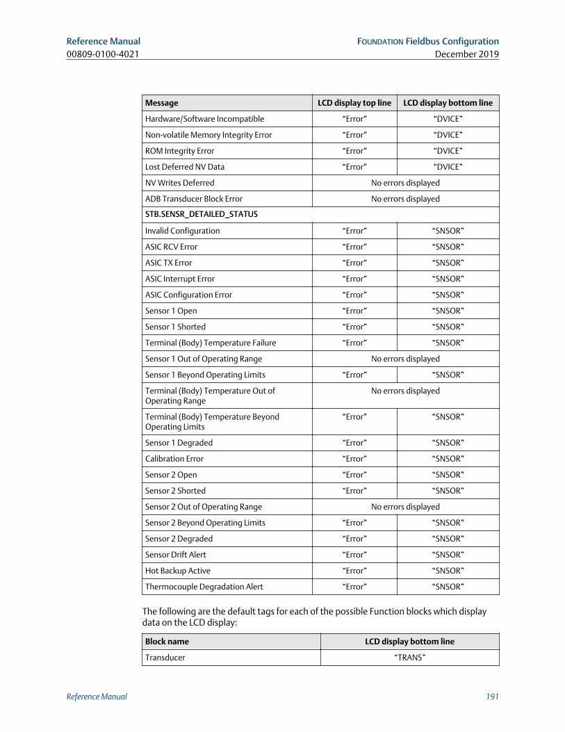
Message LCD display top line LCD display bottom line
Hardware/Software Incompatible “Error” “DVICE”
Non-volatile Memory Integrity Error “Error” “DVICE”
ROM Integrity Error “Error” “DVICE”
Lost Deferred NV Data “Error” “DVICE”
NV Writes Deferred No errors displayed
ADB Transducer Block Error No errors displayed
STB.SENSR_DETAILED_STATUS
Invalid Configuration “Error” “SNSOR”
ASIC RCV Error “Error” “SNSOR”
ASIC TX Error “Error” “SNSOR”
ASIC Interrupt Error “Error” “SNSOR”
ASIC Configuration Error “Error” “SNSOR”
Sensor 1 Open “Error” “SNSOR”
Sensor 1 Shorted “Error” “SNSOR”
Terminal (Body) Temperature Failure “Error” “SNSOR”
Sensor 1 Out of Operating Range No errors displayed
Sensor 1 Beyond Operating Limits “Error” “SNSOR”
Terminal (Body) Temperature Out ofOperating Range
No errors displayed
Terminal (Body) Temperature BeyondOperating Limits
“Error” “SNSOR”
Sensor 1 Degraded “Error” “SNSOR”
Calibration Error “Error” “SNSOR”
Sensor 2 Open “Error” “SNSOR”
Sensor 2 Shorted “Error” “SNSOR”
Sensor 2 Out of Operating Range No errors displayed
Sensor 2 Beyond Operating Limits “Error” “SNSOR”
Sensor 2 Degraded “Error” “SNSOR”
Sensor Drift Alert “Error” “SNSOR”
Hot Backup Active “Error” “SNSOR”
Thermocouple Degradation Alert “Error” “SNSOR”
The following are the default tags for each of the possible Function blocks which displaydata on the LCD display:
Block name LCD display bottom line
Transducer “TRANS”
Reference Manual FOUNDATION Fieldbus Configuration00809-0100-4021 December 2019
Reference Manual 191
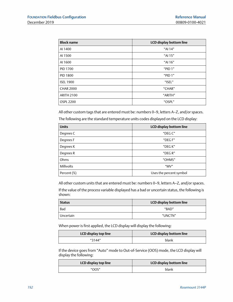
Block name LCD display bottom line
AI 1400 “AI 14”
AI 1500 “AI 15”
AI 1600 “AI 16”
PID 1700 “PID 1”
PID 1800 “PID 1”
ISEL 1900 “ISEL”
CHAR 2000 “CHAR”
ARITH 2100 “ARITH”
OSPL 2200 “OSPL”
All other custom tags that are entered must be: numbers 0–9, letters A–Z, and/or spaces.
The following are the standard temperature units codes displayed on the LCD display:
Units LCD display bottom line
Degrees C “DEG C”
Degrees F “DEG F”
Degrees K “DEG K”
Degrees R “DEG R”
Ohms “OHMS”
Millivolts “MV”
Percent (%) Uses the percent symbol
All other custom units that are entered must be: numbers 0–9, letters A–Z, and/or spaces.
If the value of the process variable displayed has a bad or uncertain status, the following isshown:
Status LCD display bottom line
Bad “BAD”
Uncertain “UNCTN”
When power is first applied, the LCD display will display the following:
LCD display top line LCD display bottom line
“3144” blank
If the device goes from “Auto” mode to Out-of-Service (OOS) mode, the LCD display willdisplay the following:
LCD display top line LCD display bottom line
“OOS” blank
FOUNDATION Fieldbus Configuration Reference ManualDecember 2019 00809-0100-4021
192 Rosemount 3144P
5 Operation and maintenance
5.1 Safety messagesInstructions and procedures in this section may require special precautions to ensure thesafety of the personnel performing the operations. Information that raises potential safetyissues is indicated by a warning symbol ( ). Refer to the following safety messages beforeperforming an operation preceded by this symbol.
5.2 MaintenanceThe transmitter has no moving parts and requires a minimum amount of scheduledmaintenance and features a modular design for easy maintenance. If a malfunction issuspected, check for an external cause before performing the diagnostics discussed in thissection.
5.2.1 Test terminal (HART®/4–20 mA only)The test terminal, marked as TEST or (“T”) on the terminal block, and the negative (–)terminal accept MINIGRABBER™, or alligator clips, facilitate in-process checks (see Figure2-14). The test and the negative terminals are connected across a diode through the loopsignal current. The current measuring equipment shunts the diode when connectedacross the test (T) and negative (–) terminals; so as long as the voltage across theterminals is kept below the diode threshold voltage, no current passes through the diode.To ensure there is no leakage current through the diode while making a test reading, orwhile an indicating meter is connected, the resistance of the test connection or metershould not exceed 10 ohms. A resistance value of 30 ohms will cause an error ofapproximately 1.0 percent of reading.
5.2.2 Sensor checkoutIf the sensor is installed in a high-voltage environment and a fault condition or installationerror occurs, the sensor leads and transmitter terminals could carry lethal voltages. Useextreme caution when making contact with the leads and terminals.
To determine whether the sensor is at fault, replace it with another sensor or connect atest sensor locally at the transmitter to test remote sensor wiring. Transmitters withoption code C7 (trim to special sensor), are matched to a specific sensor. Select astandard, off-the-shelf sensor for use with the transmitter, or consult the factory for areplacement special sensor/transmitter combination.
5.2.3 Electronics housingThe transmitter is designed with a dual-compartment housing. One compartmentcontains the electronics module, and the other contains all wiring terminals andcommunication receptacles.
Reference Manual Operation and maintenance00809-0100-4021 December 2019
Reference Manual 193
Removing the electronics moduleNoteThe electronics are sealed in a moisture-resistant plastic enclosure referred to as theelectronics module. This module is a non-repairable unit and the entire unit must bereplaced if a malfunction occurs.
The transmitter electronics module is located in the compartment opposite the wiringterminals.
Use the following procedure to remove the electronics module:
Procedure
1. Disconnect the power to the transmitter.
2. Remove the cover from the electronics side of the transmitter housing. Do notremove the covers in explosive atmospheres with a live circuit. Remove the LCDdisplay, if applicable.
3. Loosen the two screws anchoring the electronics module assembly to thetransmitter housing.
4. Firmly grasp the screws and assembly and pull straight out of the housing, takingcare not to damage the interconnecting pins.
If you are replacing the electronics module with a new one, make sure that thealarm switches are set in the same positions.
Replacing the electronics moduleUse the following procedure to reassemble the electronics housing for the transmitter:
Procedure
1. Examine the electronics module to ensure that the failure mode and transmittersecurity switches are in the desired positions.
2. Carefully insert the electronics module lining up the interconnecting pins with thenecessary receptacles on the electronics board.
3. Tighten the two mounting screws. Replace the LCD display, if applicable.
4. Replace the cover. Tighten of a revolution after the cover begins to compress the O-ring. Both transmitter covers must be fully engaged to meet explosion proofrequirements.
5.2.4 Transmitter diagnostics loggingThe Transmitter Diagnostics Logging feature stores advanced diagnostic informationbetween device resets, such as what caused the transmitter to go into alarm, even if thatevent has disappeared. For example, if the transmitter detects an open sensor from aloose terminal connection, the transmitter will go into alarm. If wire vibration causes thatwire to begin making a good connection, the transmitter will come out of alarm. Thisjumping in and out of alarm is frustrating when trying to determine what is causing theproblem. However, the Transmitter Diagnostics Logging feature keeps track of whatcaused the transmitter to go into alarm and saves valuable debugging time. The log maybe viewed using an asset management software, such as AMS Device Manager.
Operation and maintenance Reference ManualDecember 2019 00809-0100-4021
194 Rosemount 3144P
5.3 Return of materialsTo expedite the return process in North America, call the Emerson National ResponseCenter (1-800-654-7768) for assistance with any needed information or materials.
The center will ask for the following information:
• Product model
• Serial numbers
• The last process material to which the product was exposed
The center will provide
• A Return Material Authorization (RMA) number
• Instructions and procedures to return goods that were exposed to hazardoussubstances
For other locations, contact an Emerson representative.
NoteIf a hazardous substance is identified, a Safety Data Sheet (SDS), required by law to beavailable to people exposed to specific hazardous substances, must be included with thereturned materials.
Reference Manual Operation and maintenance00809-0100-4021 December 2019
Reference Manual 195

Operation and maintenance Reference ManualDecember 2019 00809-0100-4021
196 Rosemount 3144P

6 Safety Instrumented Systems (SIS)requirements
6.1 SIS certificationThe safety-critical output of the Rosemount™ 3144P Temperature Transmitter is providedthrough a two-wire, 4–20 mA signal representing temperature. The Rosemount 3144PTransmitter can be equipped with or without a display. The Rosemount 3144P SafetyCertified Safety Transmitter is certified to: Low demand; Type B.
• SIL 2 for random integrity at HFT=0
• SIL 3 for random integrity at HFT=1
• SIL 3 for systematic integrity
6.2 Safety certified identificationAll Rosemount 3144P HART® Transmitters must be identified as safety certified beforeinstalling into SIS systems.
To identify a safety certified Rosemount 3144P Transmitter, make sure the device satisfiesthe requirements below:
1. Verify the transmitter was ordered with output option code “A” and option code“QT”. This signifies that it is a 4–20mA/HART safety certified device. For example:MODEL 3144PDxA………QT....
2. Devices used in safety applications with ambient temperature below –40 °F (–40 °C)requires option code QT and BR6
3. Check the Namur Software Revision located on the adhesive transmitter tag. “SWRev _._._”. If the Device label software revision is 1.1.1 or higher, the device issafety certified.
6.3 InstallationInstallation is to be performed by qualified personnel. No special installation is required inaddition to the standard installation practices outlined in this document. Always ensure aproper seal by installing the electronics housing cover(s) so that metal contacts metal.
The loop should be designed so the terminal voltage does not drop below 12 Vdc whenthe transmitter output is 24.5 mA.
Environmental limits are available in the Rosemount 3144P Temperature TransmitterProduct Page.
Reference Manual Safety Instrumented Systems (SIS) requirements00809-0100-4021 December 2019
Reference Manual 197
6.4 ConfigurationUse any HART Protocol capable configuration tool to communicate with and verify theinitial configuration or any configuration changes made to the transmitter prior tooperating in Safety Mode. All configuration methods outlined in are the same for thesafety certified transmitter with any differences noted.
Software or hardware lock must be used in order to prevent unwanted changes to thetransmitter configuration.
NoteTransmitter output is not safety-rated during the following: Configuration changes,Multidrop operation, Simulation, Active Calibrator mode, and loop tests. Alternativemeans should be used to ensure process safety during transmitter configuration andmaintenance activities.
Safety Instrumented Systems (SIS) requirements Reference ManualDecember 2019 00809-0100-4021
198 Rosemount 3144P
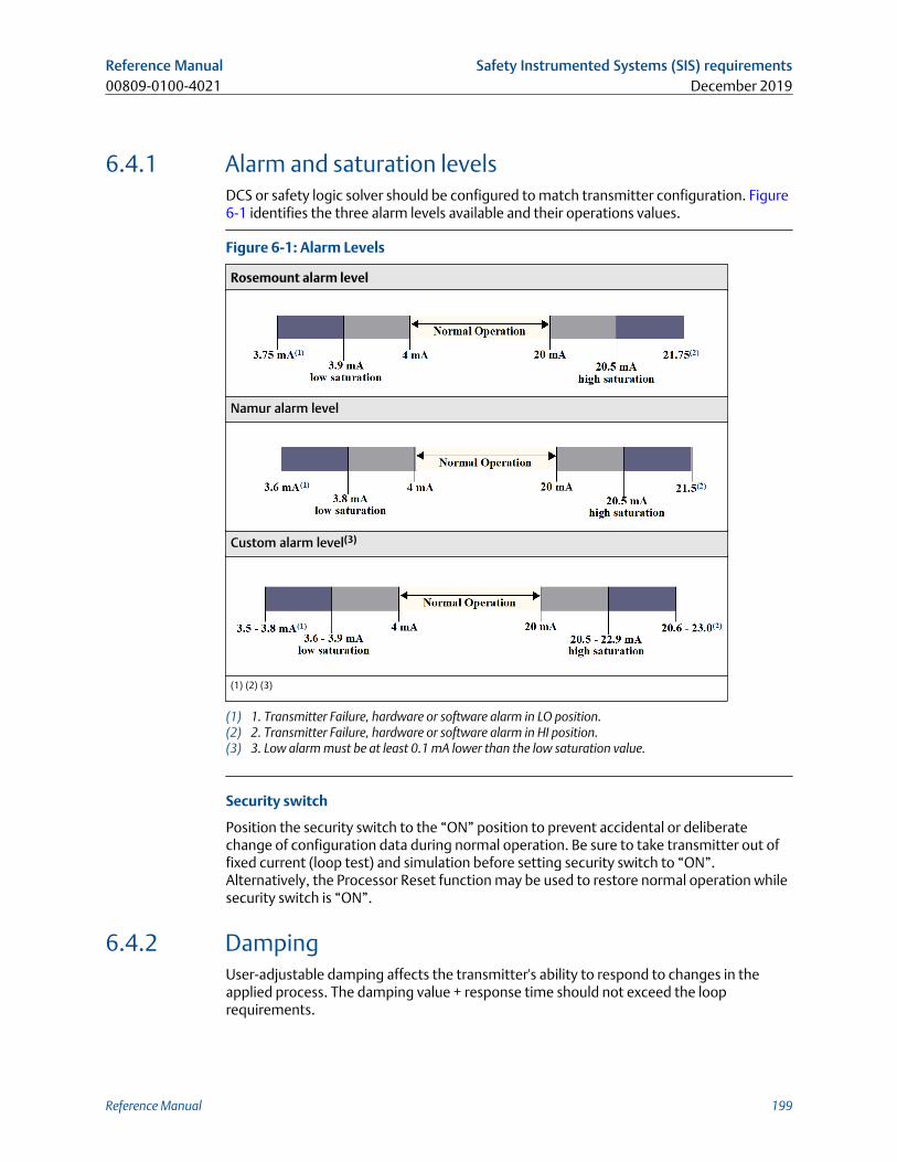
6.4.1 Alarm and saturation levelsDCS or safety logic solver should be configured to match transmitter configuration. Figure6-1 identifies the three alarm levels available and their operations values.
Figure 6-1: Alarm Levels
Rosemount alarm level
Namur alarm level
Custom alarm level(3)
(1) (2) (3)
(1) 1. Transmitter Failure, hardware or software alarm in LO position.(2) 2. Transmitter Failure, hardware or software alarm in HI position.(3) 3. Low alarm must be at least 0.1 mA lower than the low saturation value.
Security switch
Position the security switch to the “ON” position to prevent accidental or deliberatechange of configuration data during normal operation. Be sure to take transmitter out offixed current (loop test) and simulation before setting security switch to “ON”.Alternatively, the Processor Reset function may be used to restore normal operation whilesecurity switch is “ON”.
6.4.2 DampingUser-adjustable damping affects the transmitter's ability to respond to changes in theapplied process. The damping value + response time should not exceed the looprequirements.
Reference Manual Safety Instrumented Systems (SIS) requirements00809-0100-4021 December 2019
Reference Manual 199
If using a thermowell assembly, make sure to also take into account the added responsedue to thermowell material.
6.5 Operation and maintenanceProof test
The following proof tests are recommended. In the event that an error is found in thesafety functionality, proof test results and corrective actions taken must be documentedat Emerson.com/Rosemount/Safety.
All proof test procedures must be carried out by qualified personnel.
6.5.1 Partial proof test 1The partial proof test 1 consists of a power cycle plus reasonability checks of thetransmitter output. Reference the FMEDA Report for percent of possible DU failures in thedevice.
FMEDA report can be found at Rosemount 3144P Temperature Transmitter Product Page.
Required tools: Field Communicator, mA meter
Procedure
1. Bypass the safety PLC or take other appropriate action to avoid a false trip.
2. Send a HART command to the transmitter to go to high alarm current output andverify that the analog current reaches that value. This tests for compliance voltageproblems such as low loop power supply voltage or increased wiring resistance. Thisalso tests for other possible failures.
3. Send a HART command to the transmitter to go to the low alarm current outputand verify that the analog current reaches that value. This tests for possiblequiescent current related failures.
4. Use the HART communicator to view detailed device status to ensure no alarms orwarnings are present in the transmitter.
5. Perform reasonability check on the sensor value(s) versus an independent estimate(i.e. from direct monitoring of BPCS value) to show current reading is good.
6. Restore the loop to full operation.
7. Remove the bypass from the safety PLC or otherwise restore to normal operation.
6.5.2 Comprehensive proof test 2The comprehensive proof test 2 consists of performing the same steps as the partial prooftest but with a 2-point calibration of the temperature sensor in place of the reasonabilitycheck. Reference the FMEDA report for percent of possible DU failures in the device.
Required tools: Field Communicator, temperature calibration equipment
Procedure
1. Bypass the safety PLC or take other appropriate action to avoid a false trip.
Safety Instrumented Systems (SIS) requirements Reference ManualDecember 2019 00809-0100-4021
200 Rosemount 3144P
2. Perform partial proof test 1.
3. Verify the measurement for two temperature points for Sensor 1. Verify themeasurement for two temperature points for Sensor 2, if second sensor is present.
4. Perform reasonability check of the housing temperature.
5. Restore the loop to full operation.
6. Remove the bypass from the safety PLC or otherwise restore to normal operation.
6.5.3 Comprehensive proof test 3The comprehensive proof test 3 includes a comprehensive proof test along with a simplesensor proof test. Reference the FMEDA report for percent of possible DU failures in thedevice.
Procedure
1. Bypass the safety PLC or take other appropriate action to avoid a false trip.
2. Perform simple proof test 1.
3. Connect calibrated sensor simulator in place of sensor 1.
4. Verify safety accuracy of 2 temperature points inputs to transmitter.
5. If sensor 2 is used, repeat Step 3 and Step 4.
6. Restore sensor connections to transmitter.
7. Perform reasonability check of transmitter housing temperature.
8. Perform reasonability check on the sensor(s) values versus an independent estimate(i.e. from direct monitoring of BPCS value) to show current reading is acceptable.
9. Restore loop to full operation.
10. Remove the bypass from the safety PLC or otherwise restore to normal operation.
6.5.4 InspectionVisual inspection Not required.
Special tools Not required.
Product repair
The transmitter is repairable by major component replacement.
All failures detected by the transmitter diagnosticsor by the proof-test must be reported.Feedback can be submitted electronically at Emerson.com/Rosemount/Contact-Us.
6.6 SpecificationsThe transmitter must be operated according to the functional and performancespecifications provided in the Rosemount 3144P Product Data Sheet.
Failure rate data
The FMEDA report includes failure rates and independent information on generic sensormodels.
Reference Manual Safety Instrumented Systems (SIS) requirements00809-0100-4021 December 2019
Reference Manual 201
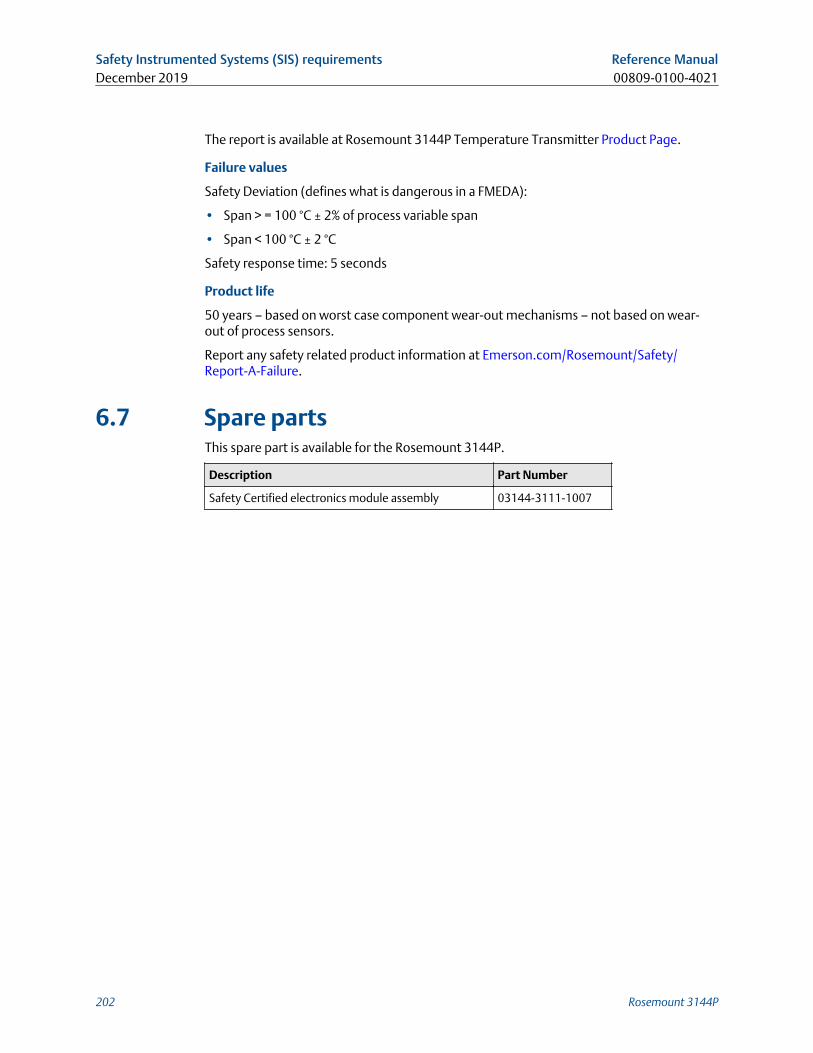
The report is available at Rosemount 3144P Temperature Transmitter Product Page.
Failure values
Safety Deviation (defines what is dangerous in a FMEDA):
• Span > = 100 °C ± 2% of process variable span
• Span < 100 °C ± 2 °C
Safety response time: 5 seconds
Product life
50 years – based on worst case component wear-out mechanisms – not based on wear-out of process sensors.
Report any safety related product information at Emerson.com/Rosemount/Safety/Report-A-Failure.
6.7 Spare partsThis spare part is available for the Rosemount 3144P.
Description Part Number
Safety Certified electronics module assembly 03144-3111-1007
Safety Instrumented Systems (SIS) requirements Reference ManualDecember 2019 00809-0100-4021
202 Rosemount 3144P
A Reference data
A.1 Product CertificationsTo view current Rosemount™ 3144P Temperature Transmitter Product Certifications,follow these steps:
Procedure
1. Go to Emerson.com/Rosemount/Rosemount-3144.
2. Scroll as needed to the green menu bar and click Documents & Drawings.
3. Click Manuals & Guides.
4. Select the appropriate Quick Start Guide.
A.2 Ordering Information, Specifications, andDrawingsTo view current Rosemount 3144P Temperature Transmitter Ordering Information,Specifications, and Drawings, follow these steps:
Procedure
1. Go to Emerson.com/Rosemount/Rosemount-3144.
2. Scroll as needed to the green menu bar and click Documents & Drawings.
3. For installation drawings, click Drawings & Schematics.
4. Select the appropriate document.
For ordering information, specifications, and dimensional drawings, click DataSheets & Bulletins and select the appropriate Product Data Sheet.
Reference Manual Reference data00809-0100-4021 December 2019
Reference Manual 203

00809-0100-4021Rev. JC
2019
Global HeadquartersEmerson Automation Solutions6021 Innovation Blvd.Shakopee, MN 55379, USA
+1 800 999 9307 or +1 952 906 8888
+1 952 204 8889
North America Regional OfficeEmerson Automation Solutions8200 Market Blvd.Chanhassen, MN 55317, USA
+1 800 999 9307 or +1 952 906 8888
+1 952 204 8889
Latin America Regional OfficeEmerson Automation Solutions1300 Concord Terrace, Suite 400Sunrise, FL 33323, USA
+1 954 846 5030
+1 954 846 5121
Europe Regional OfficeEmerson Automation Solutions EuropeGmbHNeuhofstrasse 19a P.O. Box 1046CH 6340 BaarSwitzerland
+41 (0) 41 768 6111
+41 (0) 41 768 6300
Asia Pacific Regional OfficeEmerson Automation Solutions1 Pandan CrescentSingapore 128461
+65 6777 8211
+65 6777 0947
Middle East and Africa Regional OfficeEmerson Automation SolutionsEmerson FZE P.O. Box 17033Jebel Ali Free Zone - South 2Dubai, United Arab Emirates
+971 4 8118100
+971 4 8865465
Linkedin.com/company/Emerson-Automation-Solutions
Twitter.com/Rosemount_News
Facebook.com/Rosemount
Youtube.com/user/RosemountMeasurement
©2019 Emerson. All rights reserved.
Emerson Terms and Conditions of Sale are available upon request. The Emerson logo is atrademark and service mark of Emerson Electric Co. Rosemount is a mark of one of theEmerson family of companies. All other marks are the property of their respective owners.
Related Documents