Manual PLC Lib: Tc2_MC2 TwinCAT 3 1.6 2017-08-08 Version: Date:

Welcome message from author
This document is posted to help you gain knowledge. Please leave a comment to let me know what you think about it! Share it to your friends and learn new things together.
Transcript
Manual
PLC Lib: Tc2_MC2
TwinCAT 3
1.62017-08-08
Version:Date:

Table of Contents
PLC Lib: Tc2_MC2 3Version: 1.6
Table of Contents1 Foreword .................................................................................................................................................... 7
1.1 Notes on the documentation........................................................................................................... 71.2 Safety instructions .......................................................................................................................... 8
2 Overview..................................................................................................................................................... 9
3 State diagram........................................................................................................................................... 10
4 General rules for MC function blocks.................................................................................................... 13
5 Organisation function blocks................................................................................................................. 165.1 Axis functions................................................................................................................................ 16
5.1.1 MC_Power ....................................................................................................................... 165.1.2 MC_Reset ........................................................................................................................ 175.1.3 MC_SetPosition ............................................................................................................... 18
5.2 Status and parameter ................................................................................................................... 195.2.1 MC_ReadActualPosition .................................................................................................. 195.2.2 MC_ReadActualVelocity .................................................................................................. 205.2.3 MC_ReadAxisComponents.............................................................................................. 215.2.4 MC_ReadAxisError .......................................................................................................... 225.2.5 MC_ReadBoolParameter ................................................................................................. 235.2.6 MC_ReadParameter ........................................................................................................ 245.2.7 MC_ReadParameterSet................................................................................................... 255.2.8 MC_ReadStatus............................................................................................................... 265.2.9 MC_WriteBoolParameter ................................................................................................. 275.2.10 MC_WriteParameter ........................................................................................................ 285.2.11 MC_WriteBoolParameterPersistent ................................................................................. 295.2.12 MC_WriteParameterPersistent ........................................................................................ 30
5.3 Touch probe.................................................................................................................................. 315.3.1 MC_TouchProbe.............................................................................................................. 315.3.2 MC_AbortTrigger.............................................................................................................. 34
5.4 External set value generator......................................................................................................... 355.4.1 MC_ExtSetPointGenEnable............................................................................................. 355.4.2 MC_ExtSetPointGenDisable............................................................................................ 365.4.3 MC_ExtSetPointGenFeed................................................................................................ 37
5.5 Special extensions........................................................................................................................ 385.5.1 MC_PowerStepper........................................................................................................... 385.5.2 Notes on the MC_PowerStepper ..................................................................................... 395.5.3 MC_OverrideFilter............................................................................................................ 445.5.4 MC_SetOverride .............................................................................................................. 455.5.5 MC_SetEncoderScalingFactor......................................................................................... 465.5.6 MC_ReadDriveAddress ................................................................................................... 475.5.7 MC_PositionCorrectionLimiter ......................................................................................... 485.5.8 MC_SetAcceptBlockedDriveSignal .................................................................................. 49
6 Motion function blocks ........................................................................................................................... 506.1 Point to point motion ..................................................................................................................... 50
6.1.1 MC_MoveAbsolute........................................................................................................... 506.1.2 MC_MoveRelative............................................................................................................ 516.1.3 MC_MoveAdditive ............................................................................................................ 536.1.4 MC_MoveModulo ............................................................................................................. 556.1.5 Notes on modulo positioning............................................................................................ 576.1.6 MC_MoveVelocity ............................................................................................................ 626.1.7 MC_MoveContinuousAbsolute ........................................................................................ 63
Table of Contents
PLC Lib: Tc2_MC24 Version: 1.6
6.1.8 MC_MoveContinuousRelative ......................................................................................... 656.1.9 MC_Halt ........................................................................................................................... 666.1.10 MC_Stop .......................................................................................................................... 68
6.2 Superposition................................................................................................................................ 706.2.1 MC_MoveSuperimposed ................................................................................................. 706.2.2 Application examples for MC_MoveSuperimposed ......................................................... 726.2.3 MC_AbortSuperposition................................................................................................... 75
6.3 Homing ......................................................................................................................................... 766.3.1 MC_Home........................................................................................................................ 76
6.4 Manual motion .............................................................................................................................. 786.4.1 MC_Jog............................................................................................................................ 78
6.5 Axis coupling................................................................................................................................. 806.5.1 MC_GearIn....................................................................................................................... 806.5.2 MC_GearInDyn ................................................................................................................ 826.5.3 MC_GearOut.................................................................................................................... 836.5.4 MC_GearInMultiMaster .................................................................................................... 84
6.6 Phasing......................................................................................................................................... 866.6.1 MC_HaltPhasing .............................................................................................................. 866.6.2 MC_PhasingAbsolute ...................................................................................................... 886.6.3 MC_PhasingRelative ....................................................................................................... 89
7 Data types ................................................................................................................................................ 917.1 Axis interface ................................................................................................................................ 91
7.1.1 AXIS_REF........................................................................................................................ 917.1.2 NCTOPLC_AXIS_REF..................................................................................................... 927.1.3 NCTOPLC_AXIS_REF_OPMODE................................................................................... 957.1.4 NCTOPLC_AXIS_REF_STATE....................................................................................... 957.1.5 NCTOPLC_AXIS_REF_STATE2..................................................................................... 977.1.6 NCTOPLC_AXIS_REF_STATE2_FLAGS ....................................................................... 977.1.7 NCTOPLC_AXIS_REF_CAMCOUPLINGSTATE ............................................................ 977.1.8 PLCTONC_AXIS_REF..................................................................................................... 987.1.9 PLCTONC_AXIS_REF_CTRL ......................................................................................... 99
7.2 Motion function blocks ............................................................................................................... 1007.2.1 E_JogMode.................................................................................................................... 1007.2.2 E_SuperpositionMode.................................................................................................... 1007.2.3 MC_AxisStates............................................................................................................... 1017.2.4 MC_BufferMode............................................................................................................. 1027.2.5 MC_Direction ................................................................................................................. 1047.2.6 MC_HomingMode .......................................................................................................... 1057.2.7 ST_AxisOpModes .......................................................................................................... 1057.2.8 ST_SuperpositionOptions .............................................................................................. 106
7.3 Status and parameter ................................................................................................................. 1077.3.1 E_ReadMode ................................................................................................................. 1077.3.2 MC_AxisParameter ........................................................................................................ 1077.3.3 ST_AxisParameterSet.................................................................................................... 1097.3.4 ST_AxisStatus................................................................................................................ 1107.3.5 ST_DriveAddress........................................................................................................... 1117.3.6 ST_PowerStepperStruct ................................................................................................ 1117.3.7 E_AxisPositionCorrectionMode ..................................................................................... 112
7.4 External set value generator....................................................................................................... 1127.4.1 E_PositionType.............................................................................................................. 112
7.5 Touch probe................................................................................................................................ 1127.5.1 TRIGGER_REF.............................................................................................................. 1127.5.2 MC_TouchProbeRecordedData..................................................................................... 114
Table of Contents
PLC Lib: Tc2_MC2 5Version: 1.6
8 Global constants ................................................................................................................................... 1158.1 Library version ............................................................................................................................ 115
9 Samples.................................................................................................................................................. 1169.1 Summary of examples ................................................................................................................ 116

Table of Contents
PLC Lib: Tc2_MC26 Version: 1.6
Foreword
PLC Lib: Tc2_MC2 7Version: 1.6
1 Foreword
1.1 Notes on the documentationThis description is only intended for the use of trained specialists in control and automation engineering whoare familiar with the applicable national standards.It is essential that the documentation and the following notes and explanations are followed when installingand commissioning the components. It is the duty of the technical personnel to use the documentation published at the respective time of eachinstallation and commissioning.
The responsible staff must ensure that the application or use of the products described satisfy all therequirements for safety, including all the relevant laws, regulations, guidelines and standards.
Disclaimer
The documentation has been prepared with care. The products described are, however, constantly underdevelopment.We reserve the right to revise and change the documentation at any time and without prior announcement.No claims for the modification of products that have already been supplied may be made on the basis of thedata, diagrams and descriptions in this documentation.
Trademarks
Beckhoff®, TwinCAT®, EtherCAT®, Safety over EtherCAT®, TwinSAFE®, XFC® and XTS® are registeredtrademarks of and licensed by Beckhoff Automation GmbH.Other designations used in this publication may be trademarks whose use by third parties for their ownpurposes could violate the rights of the owners.
Patent Pending
The EtherCAT Technology is covered, including but not limited to the following patent applications andpatents:EP1590927, EP1789857, DE102004044764, DE102007017835with corresponding applications or registrations in various other countries.
The TwinCAT Technology is covered, including but not limited to the following patent applications andpatents:EP0851348, US6167425 with corresponding applications or registrations in various other countries.
EtherCAT® is registered trademark and patented technology, licensed by Beckhoff Automation GmbH,Germany
Copyright
© Beckhoff Automation GmbH & Co. KG, Germany.The reproduction, distribution and utilization of this document as well as the communication of its contents toothers without express authorization are prohibited.Offenders will be held liable for the payment of damages. All rights reserved in the event of the grant of apatent, utility model or design.
Foreword
PLC Lib: Tc2_MC28 Version: 1.6
1.2 Safety instructions
Safety regulations
Please note the following safety instructions and explanations!Product-specific safety instructions can be found on following pages or in the areas mounting, wiring,commissioning etc.
Exclusion of liability
All the components are supplied in particular hardware and software configurations appropriate for theapplication. Modifications to hardware or software configurations other than those described in thedocumentation are not permitted, and nullify the liability of Beckhoff Automation GmbH & Co. KG.
Personnel qualification
This description is only intended for trained specialists in control, automation and drive engineering who arefamiliar with the applicable national standards.
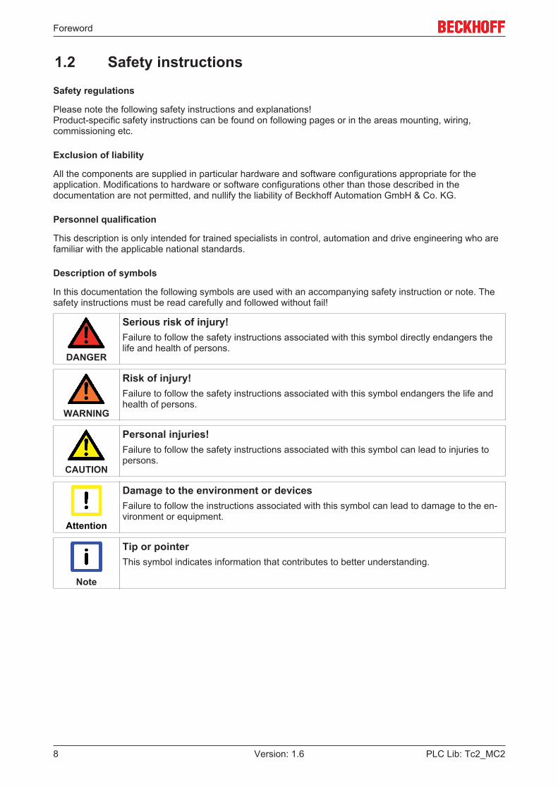
Description of symbols
In this documentation the following symbols are used with an accompanying safety instruction or note. Thesafety instructions must be read carefully and followed without fail!
DANGER
Serious risk of injury!Failure to follow the safety instructions associated with this symbol directly endangers thelife and health of persons.
WARNING
Risk of injury!Failure to follow the safety instructions associated with this symbol endangers the life andhealth of persons.
CAUTION
Personal injuries!Failure to follow the safety instructions associated with this symbol can lead to injuries topersons.
Attention
Damage to the environment or devicesFailure to follow the instructions associated with this symbol can lead to damage to the en-vironment or equipment.
Note
Tip or pointerThis symbol indicates information that contributes to better understanding.
Overview
PLC Lib: Tc2_MC2 9Version: 1.6
2 OverviewThe Tc2_MC2 TwinCAT motion control PLC library includes function blocks for programming machineapplications. Tc2_MC2 is based on the revised PLCopen specification for motion control function blocksV2.0 (www.PLCopen.org).
NOTE! It is a converted TwinCAT 2 TcMC2 library. This represented a further development of theTwinCAT 2 TcMC library. Projects using the old TcMC library first has to be adapted to TcMC2 librarybefore they can be converted to TwinCAT 3.
State diagram
PLC Lib: Tc2_MC210 Version: 1.6
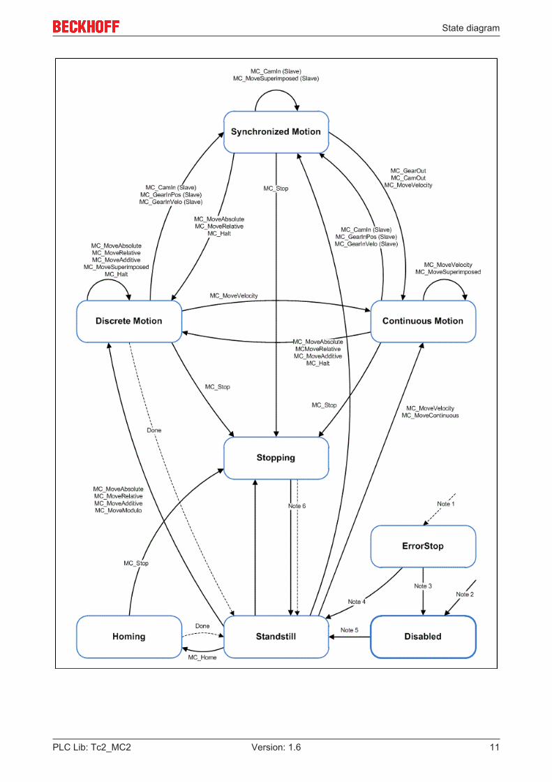
3 State diagramThe following state diagram defines the behavior of an axis in situations where several function blocks aresimultaneously active for this axis. The combination of several function blocks is useful for generating morecomplex motion profiles or for dealing with exceptional situations during program execution.
State diagram
PLC Lib: Tc2_MC2 11Version: 1.6
State diagram
PLC Lib: Tc2_MC212 Version: 1.6
Note 1 From any state. An error in the axis occurred.Note 2 From any state. MC_Power.Enable = FALSE and
there is no error in the axis.Note 3 MC_Reset AND MC_Power.Status = FALSENote 4 MC_Reset AND MC_Power.Status = TRUE AND
MC_Power.Enable = TRUENote 5 MC_Power.Enable = TRUE AND MC_Power.Status
= TRUENote 6 MC_Stop.Done = TRUE AND MC_Stop.Execute =
FALSE
As a basic rule, travel commands are processed sequentially. All commands operate within this axis statediagram.
The axis is always in one of the defined states. Motion commands resulting in a transition change the axisstate and, as a result, the motion profile. The state diagram is an abstraction layer that reflects the real axisstate, comparable to the process image for I/O points. The axis state changes immediately when thecommand is issued.
The state diagram initially targets single axes. Multi-axis blocks such as MC_CamIn or MC_GearIn influencethe states of several axes, which can always be traced back to individual axis states of the axes involved inthe process. For example, a cam plate master can be in Continous Motion state, while the associated slaveis in Synchronized Motion state. Coupling of a slave has no influence on the state of the master.
The Disabled state is the default state of an axis. In this state can the axis cannot be moved through afunction block. If the MC_Power [} 16] block is called with Enable=TRUE, the axis changes to stateStandstill or, on error, ErrorStop. If MC_Power is called with Enable=FALSE, the state changes to Disabled
The purpose of status ErrorStop is to stop the axis and then block further commands, until a reset wastriggered. The Error state transition only refers to actual axis errors, not function block execution errors. Axiserrors may also be indicated at the error output of a function block.
Function blocks that are not listed in the state diagram have no influence on the axis state. (MC_ReadStatus;MC_ReadAxisError; MC_ReadParameter; MC_ReadBoolParameter; MC_WriteParameter;MC_WriteBoolParameter; MC_ReadActualPosition and MC_CamTableSelect.)
The Stopping state indicates that the axis is in a stop ramp. Once the axis has stopped the state changes toStandStill.
Any motion commands like MC_MoveAbsolute that lead from Synchronized Motion to another state arepossible if they are explicitly enabled in the axis parameters. Decouple commands like MC_GearOut can beused independently.
General rules for MC function blocks
PLC Lib: Tc2_MC2 13Version: 1.6
4 General rules for MC function blocksFor all MC function blocks the following rules apply, which ensure defined processing through the PLCprogram.
Exclusivity of the outputs
The outputs Busy, Done, Error and CommandAborted are mutually exclusive, i.e. only one of these outputscan be TRUE at a function block at any one time. When the Execute input becomes TRUE, one of theoutputs must become TRUE. Similarly, only one of the outputs Active, Error, Done and CommandAbortedcan be TRUE at any one time.
An exception of this rule is MC_Stop [} 68]. MC_Stop sets Done to TRUE as soon as the axis is in standstill.Busy and Active stay TRUE, since the axis is looked. After Execute is reset to FALSE, the axis is releasedand Busy as well as Active are reset to FALSE.
Initial state
The outputs Done, InGear, InSync, InVelocity, Error, ErrorID and CommandAborted are reset with a fallingedge at input Execute reset, if the function block is not active (Busy=FALSE). However, a falling edge atExecute has no influence on the command execution. Resetting Execute during command executionensures that one of the outputs is set at the end of the command for a PLC cycle. Only then are the outputsreset.
If Execute is triggered more than once while a command is executed, the function block will not executefurther commands, without providing any feedback.
Input parameters
The input parameters are read with rising edge at Execute. To change the parameters the command has tobe triggered again once it is completed, or a second instance of the function block must be triggered withnew parameters during command execution.
If an input parameter is not transferred to the function block, the last value transferred to this block remainsvalid. A meaningful default value is used for the first call.
Position and Distance
The Position input denotes a defined value within a coordinate system, while Distance is a relative measurefor the distance between two positions. Position and Distance are specified in technical units, e.g. [mm] or[°], according to the axis scaling.
Dynamic parameters
The dynamic parameters for Move functions are specified in technical units with second as timebase. If anaxis is scaled in millimetres, for example, the following units are used: Velocity [mm/s], Acceleration [mm/s2],deceleration [mm/s2], jerk [mm/s3].
Error handling
All function blocks have two error outputs for indicating errors during command execution. Error indicates theerror, ErrorID contains a supplementary error number. The outputs Done, InVelocity, InGear and InSyncindicate successful command execution and are not set if Error becomes TRUE.
Errors of different type are signalled at the function block output. The error type is not specified explicitly. Itdepends on the unique, system-wide error number.
Error types• Function block errors only related to the function block, not the axis (e.g. incorrect parameterisation).
Function block errors do not have to be reset explicitly. They are reset automatically when the Executeinput is reset.
General rules for MC function blocks
PLC Lib: Tc2_MC214 Version: 1.6
• Communication errors (the function block cannot address the axis, for example). Communication errorsusually indicate incorrect configuration or parameterisation. A reset is not possible. The function blockcan only be triggered again after the configuration was corrected.
• Axis errors (logical NC axis) usually occur during the motion (e.g. following error). They cause the axisto switch to error status. An axis error must be reset through MC_Reset [} 17].
• Drive errors (control device) may result in an axis error, i.e. an error in the logical NC axis. In manycases can axis errors and drive errors can be reset together through MC_Reset [} 17]. Depending onthe drive controller, a separate reset mechanism may be required (e.g. connection of a reset line to thecontrol device).
Behaviour of the Done output
The Done output (or alternatively InVelocity, InGear, InSync etc.) is set when a command was executedsuccessfully. If several function blocks are used for an axis and the running command is interrupted througha further block, the Done output for the first block is not set.
Behaviour of the CommandAborted output
CommandAborted is set if a command is interrupted through another block.
Behaviour of the Busy output
The Busy output indicates that the function block is active. The block can only be triggered with a rising edgeat Execute, if Busy is FALSE. Busy is immediately set with a rising edge at Execute and is only reset whenthe command was completed successful or unsuccessfully. As long as Busy is TRUE, the function blockmust be called cyclically for the command to be executed.
Behaviour of the Active output
If the axis movement is controlled by several functions, the Active output of each block indicates that the axisexecutes the command. The status Busy=TRUE and Active=FALSE means that the command is not or nolonger executed.
Enable input and Valid output
In contrast to Execute the Enable input results in an action being executed permanently and repeatedly, aslong as Enable is TRUE. MC_ReadStatus [} 26] cyclically updates the status of an axis, for example, as longas Enable is TRUE. A function block with an Enable input indicates through the Valid output that the dataindicated at the outputs are valid. The data can be updated continuously while Valid is TRUE.
BufferMode
Some function blocks have a BufferMode input for controlling the command flow with several function blocks.For example, BufferMode can specify that a command interrupts another command (non-queued mode) orthat the following command is only executed after the previous command (queued mode). In queued modeBufferMode can be used to specify the movement transition from one command to the next. This is referredto as Blending, which specifies the velocity at the transition point.
A second instance of a Move function block is required to use the BufferMode. It is not possible to trigger thesame function block with different parameters as long as it is busy.
In non-queued mode a subsequent command leads to termination of a running command. In this case theprevious command sets the CommandAborted output. In queued mode a subsequent command waits until arunning command is completed. Buffered commands are not possible if an endless motion command(MC_MoveVelocity) is active. In this case buffered commands lead to an immediate termination of theendless motion just as in non-queued mode.
Only one command is queued while another command is executed. If more than one command is triggeredwhile a command is running, the command started last for queuing is rejected with an error (Error 0x4292Buffer Full).. If the last command is started in non-queued mode (Aborting), it becomes active and interruptsthe running and an already queued command.

General rules for MC function blocks
PLC Lib: Tc2_MC2 15Version: 1.6
BufferModes• Aborting : Default mode without buffering. The command is executed immediately and interrupts any
other command that may be running.• Buffered : The command is executed once no other command is running on the axis. The previous
movement continues until it has stopped. The following command is started from standstill.• BlendingLow : The command is executed once no other command is running on the axis. In contrast to
Buffered the axis does not stop at the previous target, but passes through this position with the lowervelocity of two commands.
• BlendingHigh : The command is executed once no other command is running on the axis. In contrast toBuffered the axis does not stop at the previous target, but passes through this position with the highervelocity of two commands.
• BlendingNext : The command is executed once no other command is running on the axis. In contrast toBuffered the axis does not stop at the previous target, but passes through this position with the velocityof the last command.
• BlendingPrevious: The command is executed once no other command is running on the axis. Incontrast to Buffered the axis does not stop at the previous target, but passes through this position withthe velocity of the first command.
Graphical description of BufferModes [} 102]
Optional Blending Position
Blending is usually done at the target position of the actually executed command. In case of MoveVelocity notarget position is defined and in other cases changing the blending position might be useful. To do so, anoptional BlendingPosition can be defined using the Options Input of the function block (see below). Theoptional BlendingPosition must be located in front of the actual target position, otherwise the command willbe rejected with error (0x4296). If the optional BlendingPosition has already been overrun, the newcommand will be executed instantaneously; thus it behaves as an Aborting command.
Options input
Many function blocks have an Options input with a data structure containing additional, infrequently requiredoptions. For the basic block function these options are often not required, so that the input can remain open.The user only has to populate the Options data structure in cases where the documentation explicitly refersto certain options.
Slave Axes
Motion commands like MC_MoveAbsolute can be passed to slave axes if they are explicitly enabled in theaxis parameters. A motion command will then decouple the axis and move it afterwards. In this case justBuffer-ModeAborting can be used.
Organisation function blocks
PLC Lib: Tc2_MC216 Version: 1.6
5 Organisation function blocks
5.1 Axis functions
5.1.1 MC_Power
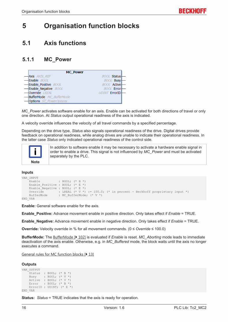
MC_Power activates software enable for an axis. Enable can be activated for both directions of travel or onlyone direction. At Status output operational readiness of the axis is indicated.
A velocity override influences the velocity of all travel commands by a specified percentage.
Depending on the drive type, Status also signals operational readiness of the drive. Digital drives providefeedback on operational readiness, while analog drives are unable to indicate their operational readiness. Inthe latter case Status only indicated operational readiness of the control side.
Note
In addition to software enable it may be necessary to activate a hardware enable signal inorder to enable a drive. This signal is not influenced by MC_Power and must be activatedseparately by the PLC.
InputsVAR_INPUT Enable : BOOL; (* B *) Enable_Positive : BOOL; (* E *) Enable_Negative : BOOL; (* E *) Override : LREAL (* V *) := 100.0; (* in percent - Beckhoff proprietary input *) BufferMode : MC_BufferMode; (* V *)END_VAR
Enable: General software enable for the axis.
Enable_Positive: Advance movement enable in positive direction. Only takes effect if Enable = TRUE.
Enable_Negative: Advance movement enable in negative direction. Only takes effect if Enable = TRUE.
Override: Velocity override in % for all movement commands. (0 ≤ Override ≤ 100.0)
BufferMode: The BufferMode [} 102] is evaluated if Enable is reset. MC_Aborting mode leads to immediatedeactivation of the axis enable. Otherwise, e.g. in MC_Buffered mode, the block waits until the axis no longerexecutes a command.
General rules for MC function blocks [} 13]
OutputsVAR_OUTPUT Status : BOOL; (* B *) Busy : BOOL; (* V *) Active : BOOL; (* V *) Error : BOOL; (* B *) ErrorID : UDINT; (* E *)END_VAR
Status: Status = TRUE indicates that the axis is ready for operation.
Organisation function blocks
PLC Lib: Tc2_MC2 17Version: 1.6
Busy: The Busy output is TRUE, as long as the function block is called up with Enable = TRUE.
Active: Indicates that the command is executed.
Error: Becomes TRUE if an error occurs.
ErrorID: If the error output is set, this parameter supplies the error number
General rules for MC function blocks [} 13]
Inputs/outputsVAR_IN_OUT Axis : AXIS_REF;END_VAR
Axis: Axis data structure of the type AXIS_REF [} 91], which uniquely addresses an axis in the system.Among other parameters it contains the current axis status, including position, velocity or error status.
Requirements
Development environment Target system type PLC libraries to includeTwinCAT v3.0.0 PC or CX (x86) Tc2_MC2
5.1.2 MC_Reset
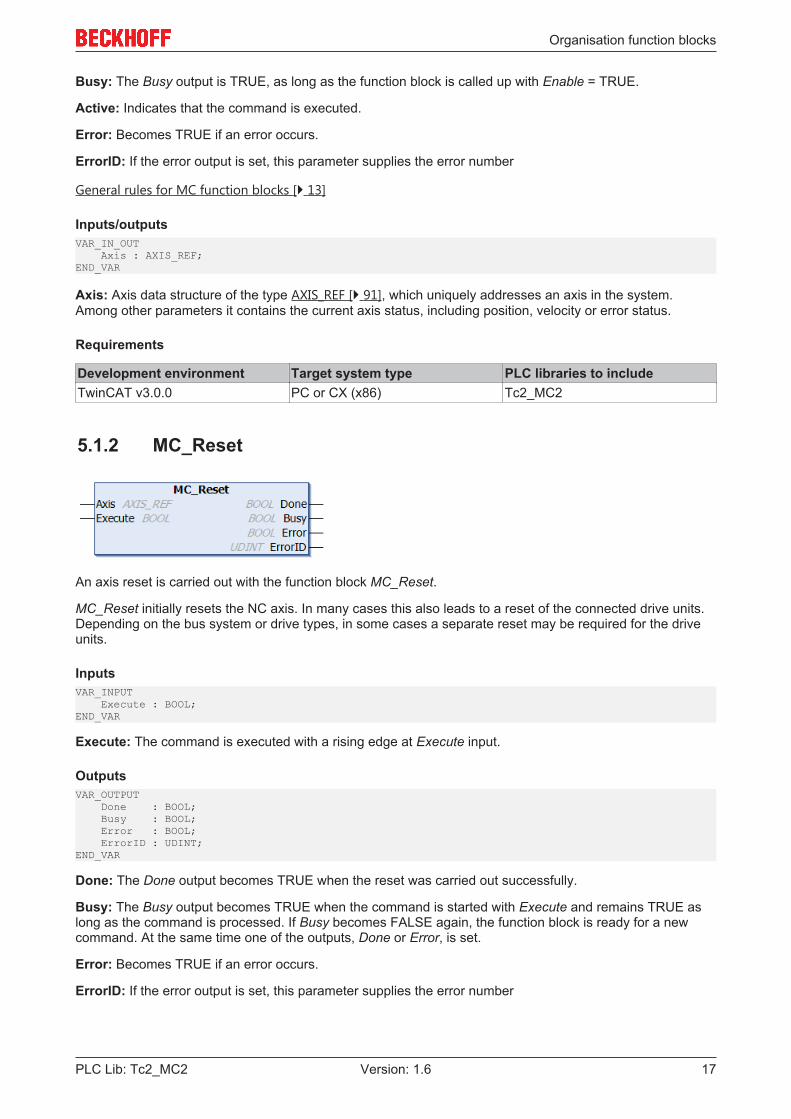
An axis reset is carried out with the function block MC_Reset.
MC_Reset initially resets the NC axis. In many cases this also leads to a reset of the connected drive units.Depending on the bus system or drive types, in some cases a separate reset may be required for the driveunits.
InputsVAR_INPUT Execute : BOOL;END_VAR
Execute: The command is executed with a rising edge at Execute input.
OutputsVAR_OUTPUT Done : BOOL; Busy : BOOL; Error : BOOL; ErrorID : UDINT;END_VAR
Done: The Done output becomes TRUE when the reset was carried out successfully.
Busy: The Busy output becomes TRUE when the command is started with Execute and remains TRUE aslong as the command is processed. If Busy becomes FALSE again, the function block is ready for a newcommand. At the same time one of the outputs, Done or Error, is set.
Error: Becomes TRUE if an error occurs.
ErrorID: If the error output is set, this parameter supplies the error number
Organisation function blocks
PLC Lib: Tc2_MC218 Version: 1.6
Inputs/outputsVAR_IN_OUT Axis : AXIS_REF;END_VAR
Axis: Axis data structure of the type AXIS_REF [} 91], which uniquely addresses an axis in the system.Among other parameters it contains the current axis status, including position, velocity or error status.
Requirements
Development environment Target system type PLC libraries to includeTwinCAT v3.0.0 PC or CX (x86) Tc2_MC2
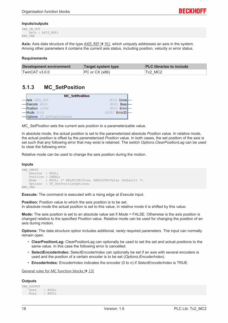
5.1.3 MC_SetPosition
MC_SetPosition sets the current axis position to a parameterizable value.
In absolute mode, the actual position is set to the parameterized absolute Position value. In relative mode,the actual position is offset by the parameterized Position value. In both cases, the set position of the axis isset such that any following error that may exist is retained. The switch Options.ClearPositionLag can be usedto clear the following error.
Relative mode can be used to change the axis position during the motion.
InputsVAR_INPUT Execute : BOOL; Position : LREAL; Mode : BOOL; (* RELATIVE=True, ABSOLUTE=False (Default) *) Options : ST_SetPositionOptions; END_VAR
Execute: The command is executed with a rising edge at Execute input.
Position: Position value to which the axis position is to be set.In absolute mode the actual position is set to this value, in relative mode it is shifted by this value.
Mode: The axis position is set to an absolute value set if Mode = FALSE. Otherwise is the axis position ischanged relative to the specified Position value. Relative mode can be used for changing the position of anaxis during motion.
Options: The data structure option includes additional, rarely required parameters. The input can normallyremain open.
• ClearPositionLag: ClearPositionLag can optionally be used to set the set and actual positions to thesame value. In this case the following error is cancelled.
• SelectEncoderIndex: SelectEncoderIndex can optionally be set if an axis with several encoders isused and the position of a certain encoder is to be set (Options.EncoderIndex).
• EncoderIndex: EncoderIndex indicates the encoder (0 to n) if SelectEncoderIndex is TRUE.
General rules for MC function blocks [} 13]
OutputsVAR_OUTPUT Done : BOOL; Busy : BOOL;
Organisation function blocks
PLC Lib: Tc2_MC2 19Version: 1.6
Error : BOOL; ErrorID : UDINT;END_VAR
Done: The Done output becomes TRUE, once the position was set successfully.
Busy: The Busy output becomes TRUE when the command is started with Execute and remains TRUE aslong as the command is processed. If Busy becomes FALSE again, the function block is ready for a new job.At the same time one of the outputs, Done or Error, is set.
Error: Becomes TRUE if an error occurs.
ErrorID: If the error output is set, this parameter supplies the error number
General rules for MC function blocks [} 13]
Inputs/outputsVAR_IN_OUT Axis : AXIS_REF;END_VAR
Axis: Axis data structure of the type AXIS_REF [} 91], which uniquely addresses an axis in the system.Among other parameters it contains the current axis status, including position, velocity or error status.
Requirements
Development environment Target system type PLC libraries to includeTwinCAT v3.0.0 PC or CX (x86) Tc2_MC2
5.2 Status and parameter
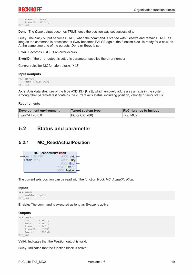
5.2.1 MC_ReadActualPosition
The current axis position can be read with the function block MC_ActualPosition.
InputsVAR_INPUT Enable : BOOL;END_VAR
Enable: The command is executed as long as Enable is active.
OutputsVAR_OUTPUT Valid : BOOL; Busy : BOOL; Error : BOOL; ErrorID : UDINT; Position : LREAL;END_VAR
Valid: Indicates that the Position output is valid.
Busy: Indicates that the function block is active.
Organisation function blocks
PLC Lib: Tc2_MC220 Version: 1.6
Error: Becomes TRUE if an error occurs.
ErrorID: If the error output is set, this parameter supplies the error number
Position: Current axis position
Inputs/outputsVAR_IN_OUT Axis : AXIS_REF;END_VAR
Axis: Axis data structure of the type AXIS_REF [} 91], which uniquely addresses an axis in the system.Among other parameters it contains the current axis status, including position, velocity or error status.
Requirements
Development environment Target system type PLC libraries to includeTwinCAT v3.0.0 PC or CX (x86) Tc2_MC2
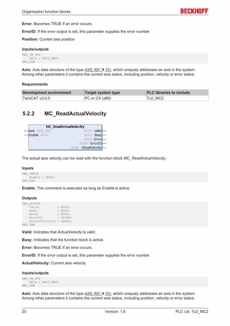
5.2.2 MC_ReadActualVelocity
The actual axis velocity can be read with the function block MC_ReadActualVelocity.
InputsVAR_INPUT Enable : BOOL;END_VAR
Enable: The command is executed as long as Enable is active.
OutputsVAR_OUTPUT Valid : BOOL; Busy : BOOL; Error : BOOL; ErrorID : UDINT; ActualVelocity : LREAL;END_VAR
Valid: Indicates that ActualVelocity is valid.
Busy: Indicates that the function block is active.
Error: Becomes TRUE if an error occurs.
ErrorID: If the error output is set, this parameter supplies the error number
ActualVelocity: Current axis velocity
Inputs/outputsVAR_IN_OUT Axis : AXIS_REF;END_VAR
Axis: Axis data structure of the type AXIS_REF [} 91], which uniquely addresses an axis in the system.Among other parameters it contains the current axis status, including position, velocity or error status.
Organisation function blocks
PLC Lib: Tc2_MC2 21Version: 1.6
Requirements
Development environment Target system type PLC libraries to includeTwinCAT v3.0.0 PC or CX (x86) Tc2_MC2
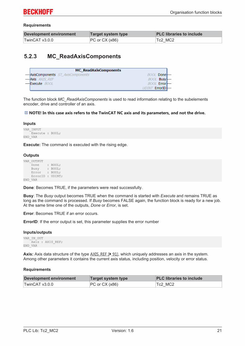
5.2.3 MC_ReadAxisComponents
The function block MC_ReadAxisComponents is used to read information relating to the subelementsencoder, drive and controller of an axis.
NOTE! In this case axis refers to the TwinCAT NC axis and its parameters, and not the drive.
InputsVAR_INPUT Execute : BOOL;END_VAR
Execute: The command is executed with the rising edge.
OutputsVAR_OUTPUT Done : BOOL; Busy : BOOL; Error : BOOL; ErrorID : UDINT;END_VAR
Done: Becomes TRUE, if the parameters were read successfully.
Busy: The Busy output becomes TRUE when the command is started with Execute and remains TRUE aslong as the command is processed. If Busy becomes FALSE again, the function block is ready for a new job.At the same time one of the outputs, Done or Error, is set.
Error: Becomes TRUE if an error occurs.
ErrorID: If the error output is set, this parameter supplies the error number
Inputs/outputsVAR_IN_OUT Axis : AXIS_REF;END_VAR
Axis: Axis data structure of the type AXIS_REF [} 91], which uniquely addresses an axis in the system.Among other parameters it contains the current axis status, including position, velocity or error status.
Requirements
Development environment Target system type PLC libraries to includeTwinCAT v3.0.0 PC or CX (x86) Tc2_MC2

Organisation function blocks
PLC Lib: Tc2_MC222 Version: 1.6
5.2.4 MC_ReadAxisError
MC_ReadAxisError reads the axis error of an axis.
InputsVAR_INPUT Enable : BOOL; (* B *)END_VAR
Enable: The axis error is output at the AxisErrorID output as long as Enable is active
General rules for MC function blocks [} 13]
OutputsVAR_OUTPUT Valid : BOOL; (* B *) Busy : BOOL; (* E *) Error : BOOL; (* B *) ErrorID : DWORD; (* B *) AxisErrorID : DWORD; (* B *)END_VAR
Valid: The error signaled at the AxisErrorID output is valid
Busy: The Busy output becomes TRUE when the command is started with Enable and remains TRUE aslong as the command is processed. If Busy becomes FALSE again, the function block is ready for a new job.
Error: Becomes TRUE if an error occurs.
ErrorID: If the error output is set, this parameter supplies the error number
AxisErrorID: Error number for the axis
General rules for MC function blocks [} 13]
Inputs/outputsVAR_IN_OUT Axis : AXIS_REF;END_VAR
Axis: Axis data structure of the type AXIS_REF [} 91], which uniquely addresses an axis in the system.Among other parameters it contains the current axis status, including position, velocity or error status.
Requirements
Development environment Target system type PLC libraries to includeTwinCAT v3.0.0 PC or CX (x86) Tc2_MC2

Organisation function blocks
PLC Lib: Tc2_MC2 23Version: 1.6
5.2.5 MC_ReadBoolParameter
The function block MC_ReadBoolParameter is used to read a boolean axis parameter.
NOTE! In this case axis refers to the TwinCAT NC axis and its parameters, and not the drive.
InputsVAR_INPUT Enable : BOOL; (* B *) ParameterNumber : MC_AxisParameter; (* B *) ReadMode : E_ReadMode (* V *)EEND_VAR
Enable: The command is executed as long as Enable is active.
ParameterNumber: Number [} 107] of the parameter to be read.
ReadMode: Read mode [} 107] of the parameter to be read (once or cyclic).
OutputsVAR_OUTPUT Valid : BOOL; (* B *) Busy : BOOL; (* E *) Error : BOOL; (* B *) ErrorID : DWORD; (* E *) Value : BOOL; (* B *)END_VAR
Valid: The value signaled at the Value output is valid.
Busy: The Busy output becomes TRUE when the command is started with Enable and remains TRUE aslong as the command is processed. If Busy becomes FALSE again, the function block is ready for a new job.
Error: Becomes TRUE if an error occurs.
ErrorID: If the error output is set, this parameter supplies the error number
Value: Displays the boolean value that was read.
Inputs/outputsVAR_IN_OUT Axis : AXIS_REF;END_VAR
Axis: Axis data structure of the type AXIS_REF [} 91], which uniquely addresses an axis in the system.Among other parameters it contains the current axis status, including position, velocity or error status.
Requirements
Development environment Target system type PLC libraries to includeTwinCAT v3.0.0 PC or CX (x86) Tc2_MC2

Organisation function blocks
PLC Lib: Tc2_MC224 Version: 1.6
5.2.6 MC_ReadParameter
The function block MC_ReadParameter is used to read an axis parameter.
NOTE! In this case axis refers to the TwinCAT NC axis and its parameters, and not the drive.
InputsVAR_INPUT Enable : BOOL; (* B *) ParameterNumber : MC_AxisParameter; (* B *) ReadMode : E_ReadMode (* V *)END_VAR
Enable: The command is executed as long as Enable is active.
ParameterNumber: Number [} 107] of the parameter to be read.
ReadMode: Read mode [} 107] of the parameter to be read (once or cyclic).
OutputsVAR_OUTPUT Valid : BOOL; (* B *) Busy : BOOL; (* E *) Error : BOOL; (* B *) ErrorID : DWORD; (* E *) Value : LREAL; (* B *)END_VAR
Valid: The value signaled at the Value output is valid
Busy: The Busy output becomes TRUE when the command is started with Enable and remains TRUE aslong as the command is processed. If Busy becomes FALSE again, the function block is ready for a new job.
Error: Becomes TRUE if an error occurs.
ErrorID: If the error output is set, this parameter supplies the error number
Value: Displays the read value.
Inputs/outputsVAR_IN_OUT Axis : AXIS_REF;END_VAR
Axis: Axis data structure of the type AXIS_REF [} 91], which uniquely addresses an axis in the system.Among other parameters it contains the current axis status, including position, velocity or error status.
Requirements
Development environment Target system type PLC libraries to includeTwinCAT v3.0.0 PC or CX (x86) Tc2_MC2
Organisation function blocks
PLC Lib: Tc2_MC2 25Version: 1.6
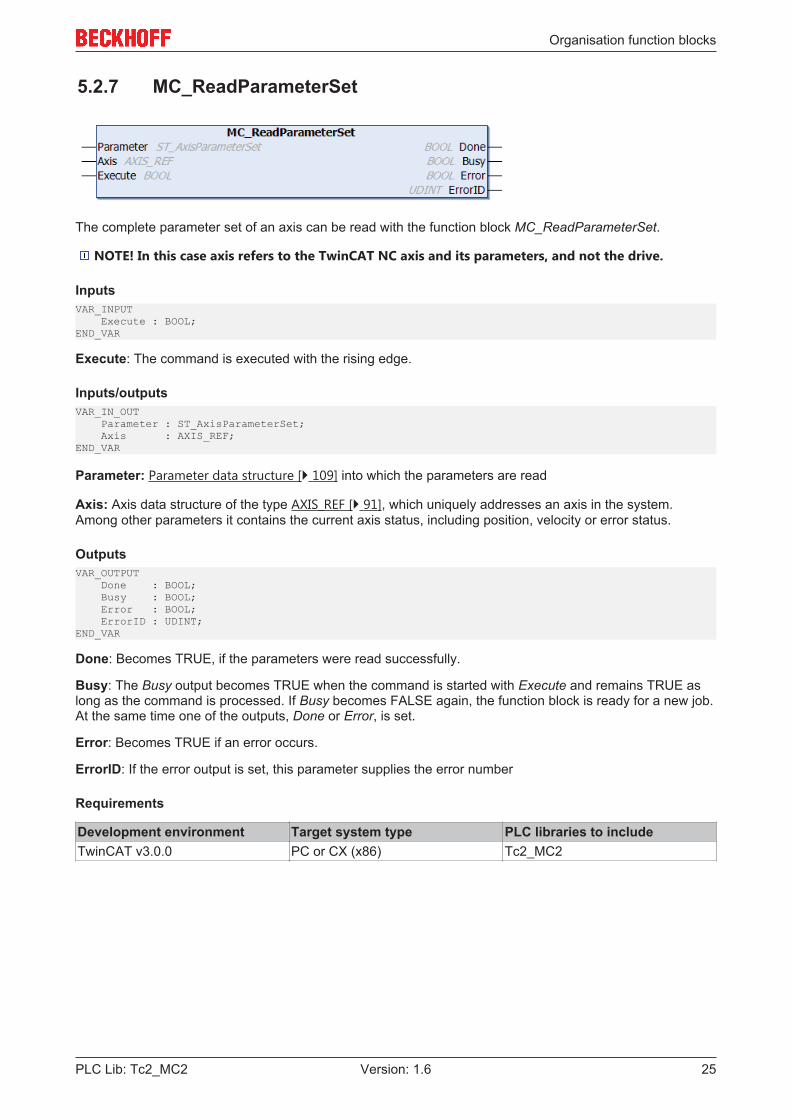
5.2.7 MC_ReadParameterSet
The complete parameter set of an axis can be read with the function block MC_ReadParameterSet.
NOTE! In this case axis refers to the TwinCAT NC axis and its parameters, and not the drive.
InputsVAR_INPUT Execute : BOOL;END_VAR
Execute: The command is executed with the rising edge.
Inputs/outputsVAR_IN_OUT Parameter : ST_AxisParameterSet; Axis : AXIS_REF;END_VAR
Parameter: Parameter data structure [} 109] into which the parameters are read
Axis: Axis data structure of the type AXIS_REF [} 91], which uniquely addresses an axis in the system.Among other parameters it contains the current axis status, including position, velocity or error status.
OutputsVAR_OUTPUT Done : BOOL; Busy : BOOL; Error : BOOL; ErrorID : UDINT;END_VAR
Done: Becomes TRUE, if the parameters were read successfully.
Busy: The Busy output becomes TRUE when the command is started with Execute and remains TRUE aslong as the command is processed. If Busy becomes FALSE again, the function block is ready for a new job.At the same time one of the outputs, Done or Error, is set.
Error: Becomes TRUE if an error occurs.
ErrorID: If the error output is set, this parameter supplies the error number
Requirements
Development environment Target system type PLC libraries to includeTwinCAT v3.0.0 PC or CX (x86) Tc2_MC2

Organisation function blocks
PLC Lib: Tc2_MC226 Version: 1.6
5.2.8 MC_ReadStatus
MC_ReadStatus determines the current operating state of an axis and signals it at the block outputs.
The updated operating state is additionally stored in the Status output data structure and in the Axis.Statusaxis data structure. This means the operating state only has to be read once at the start of each PLC cycleand can then be accessed via Axis.Status.
The Axis variable (type AXIS_REF) already includes an instance of the function block MC_ReadStatus. Thismeans that the operating state of an axis can be updated at the start of a PLC cycle by calling upAxis.ReadStatus.
Example:PROGRAM MAINVAR Axis1 : AXIS_REFEND_VAR
(* call the read status function *)Axis1.ReadStatus;
InputsVAR_INPUT Enable : BOOL; END_VAR
Enable: As long as Enable = TRUE, the axis operating state is updated with each call of the block.
General rules for MC function blocks [} 13]
OutputsVAR_OUTPUT Valid : BOOL; Busy : BOOL; Error : BOOL; ErrorId : UDINT; (* motion control statemachine states: *) ErrorStop : BOOL; Disabled : BOOL; Stopping : BOOL; StandStill : BOOL; DiscreteMotion : BOOL; ContinuousMotion : BOOL; SynchronizedMotion : BOOL; Homing : BOOL; (* additional status *) ConstantVelocity : BOOL; Accelerating : BOOL; Decelerating : BOOL;
Organisation function blocks
PLC Lib: Tc2_MC2 27Version: 1.6
(* status data structure *) Status : ST_AxisStatus; END_VAR
Valid: Indicates that the axis operating state indicated at the other outputs is valid.
Busy: Indicates that the function block is active.
Error: Becomes TRUE if an error occurs.
ErrorID: If the error output is set, this parameter supplies the error number
ErrorStop: Axis status according to the PlcOpen state diagram [} 10]
Disabled: Axis status according to the PlcOpen state diagram [} 10]
Stopping: Axis status according to the PlcOpen state diagram [} 10]
StandStill: Axis status according to the PlcOpen state diagram [} 10]
DiscreteMotion: Axis status according to the PlcOpen state diagram [} 10]
ContinousMotion: Axis status according to the PlcOpen state diagram [} 10]
SynchronizedMotion: Axis status according to the PlcOpen state diagram [} 10]
Homing: Axis status according to the PlcOpen state diagram [} 10]
ConstantVelocity: The axis is moving with constant velocity
Acceleration: The axis accelerates.
Decelerating: The axis decelerates.
Status: Extended status data structure [} 110] with additional status information.
General rules for MC function blocks [} 13]
Inputs/outputsVAR_IN_OUT Axis : AXIS_REF;END_VAR
Axis: Axis data structure of the type AXIS_REF [} 91], which uniquely addresses an axis in the system.Among other parameters it contains the current axis status, including position, velocity or error status.
Requirements
Development environment Target system type PLC libraries to includeTwinCAT v3.0.0 PC or CX (x86) Tc2_MC2
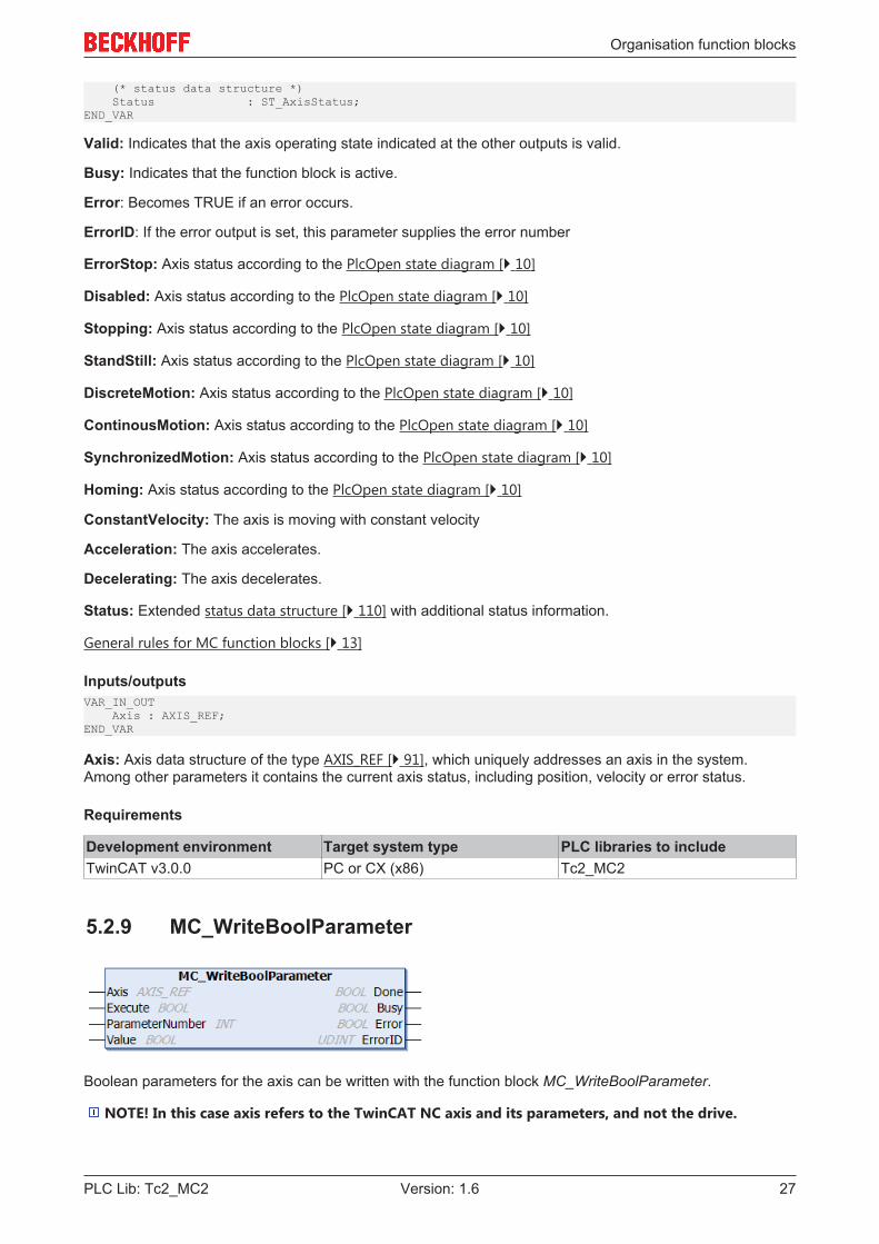
5.2.9 MC_WriteBoolParameter
Boolean parameters for the axis can be written with the function block MC_WriteBoolParameter.
NOTE! In this case axis refers to the TwinCAT NC axis and its parameters, and not the drive.
Organisation function blocks
PLC Lib: Tc2_MC228 Version: 1.6
InputsVAR_INPUT Execute : BOOL; ParameterNumber : INT; Value : BOOL;END_VAR
Execute: The command is executed with the rising edge.
ParameterNumber: Number [} 107] of the parameter to be written.
Value: This BOOL value is written.
OutputsVAR_OUTPUT Done : BOOL; Busy : BOOL; Error : BOOL; ErrorID : UDINT;END_VAR
Done: The output becomes TRUE when the parameters were written successfully.
Busy: The output becomes TRUE when the command is started with Execute and remains TRUE as long asthe command is processed. If Busy becomes FALSE again, the function block is ready for a new job. At thesame time one of the outputs, Done or Error, is set.
Error: Becomes TRUE if an error occurs.
ErrorID: If the error output is set, this parameter supplies the error number.
Inputs/outputsVAR_IN_OUT Axis : AXIS_REF;END_VAR
Axis: Axis data structure of the type AXIS_REF [} 91], which uniquely addresses an axis in the system.Among other parameters it contains the current axis status, including position, velocity or error status.
Requirements
Development environment Target system type PLC libraries to includeTwinCAT v3.0.0 PC or CX (x86) Tc2_MC2
5.2.10 MC_WriteParameter
Axis parameters can be written with the function block MC_WriteParameter.
NOTE! In this case axis refers to the TwinCAT NC axis and its parameters, and not the drive.
InputsVAR_INPUT Execute : BOOL; ParameterNumber : INT; Value : LREAL;END_VAR
Execute: The command is executed with the rising edge.
Organisation function blocks
PLC Lib: Tc2_MC2 29Version: 1.6
ParameterNumber: Number [} 107] of the parameter to be written.
Value: This LREAL value is written.
OutputsVAR_OUTPUT Done : BOOL; Busy : BOOL; Error : BOOL; ErrorID : UDINT;END_VAR
Done: The output becomes TRUE when the parameters were written successfully.
Busy: The output becomes TRUE when the command is started with Execute and remains TRUE as long asthe command is processed. If Busy becomes FALSE again, the function block is ready for a new job. At thesame time one of the outputs, Done or Error, is set.
Error: Becomes TRUE if an error occurs.
ErrorID: If the error output is set, this parameter supplies the error number.
Inputs/outputsVAR_IN_OUT Axis : AXIS_REF;END_VAR
Axis: Axis data structure of the type AXIS_REF [} 91], which uniquely addresses an axis in the system.Among other parameters it contains the current axis status, including position, velocity or error status.
Requirements
Development environment Target system type PLC libraries to includeTwinCAT v3.0.0 PC or CX (x86) Tc2_MC2
5.2.11 MC_WriteBoolParameterPersistent
Boolean axis parameters can be written persistently with the function blockMC_WriteBoolParameterPersistent.
The persistent parameter to be written is stored in an initialization list. At system startup, the system initiallystarts with the originally configured values and overwrites these with the persistent data from the initializationlist before the start of the task. The initialization list is cleared when a new system configuration is registered.The system then starts with the unchanged data from the new configuration.
NOTE! In this case axis refers to the TwinCAT NC axis and its parameters, and not the drive.
InputsVAR_INPUT Execute : BOOL; ParameterNumber : INT; Value : BOOL;END_VAR
Execute: The function block is activated via a positive flank.
ParameterNumber: Number [} 107] of the parameter to be written.
Value: BOOL value to be written.

Organisation function blocks
PLC Lib: Tc2_MC230 Version: 1.6
OutputsVAR_OUTPUT Done : BOOL; Busy : BOOL; Error : BOOL; ErrorID : UDINT;END_VAR
Done: The output becomes TRUE when the parameters were written successfully.
Busy: The output becomes TRUE when the command is started with Execute and remains TRUE as long asthe command is processed. If Busy becomes FALSE again, the function block is ready for a new job. At thesame time one of the outputs, Done or Error, is set.
Error: Becomes TRUE if an error occurs.
ErrorID: If the error output is set, this parameter supplies the error number.
Inputs/outputsVAR_IN_OUT Axis : AXIS_REF;END_VAR
Axis: Axis data structure of the type AXIS_REF [} 91], which uniquely addresses an axis in the system.Among other parameters it contains the current axis status, including position, velocity or error status.
Requirements
Development environment Target system type PLC libraries to includeTwinCAT v3.0.0 PC or CX (x86) Tc2_MC2
5.2.12 MC_WriteParameterPersistent
Axis parameters can be written persistently with the block MC_WriteParameterPersistent.
The persistent parameter to be written is stored in an initialization list. At system startup, the system initiallystarts with the originally configured values and overwrites these with the persistent data from the initializationlist before the start of the task. The initialization list is cleared when a new system configuration is registered.The system then starts with the unchanged data from the new configuration.
NOTE! In this case axis refers to the TwinCAT NC axis and its parameters, and not the drive.
InputsVAR_INPUT Execute : BOOL; ParameterNumber : INT; Value : LREAL;END_VAR
Execute: The function block is activated via a positive flank.
ParameterNumber: Number [} 107] of the parameter to be written.
Value: LREAL value that is written.
OutputsVAR_OUTPUT Done : BOOL; Busy : BOOL;
Organisation function blocks
PLC Lib: Tc2_MC2 31Version: 1.6
Error : BOOL; ErrorID : UDINT;END_VAR
Done: The output becomes TRUE when the parameters were written successfully.
Busy: The output becomes TRUE when the command is started with Execute and remains TRUE as long asthe command is processed. If Busy becomes FALSE again, the function block is ready for a new job. At thesame time one of the outputs, Done or Error, is set.
Error: Becomes TRUE if an error occurs.
ErrorID: If the error output is set, this parameter supplies the error number.
Inputs/outputsVAR_IN_OUT Axis : AXIS_REF;END_VAR
Axis: Axis data structure of the type AXIS_REF [} 91], which uniquely addresses an axis in the system.Among other parameters it contains the current axis status, including position, velocity or error status.
Requirements
Development environment Target system type PLC libraries to includeTwinCAT v3.0.0 PC or CX (x86) Tc2_MC2
5.3 Touch probe
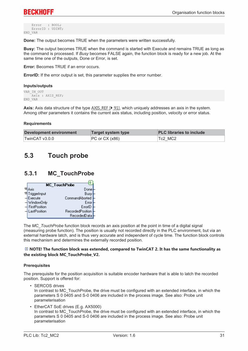
5.3.1 MC_TouchProbe
The MC_TouchProbe function block records an axis position at the point in time of a digital signal(measuring probe function). The position is usually not recorded directly in the PLC environment, but via anexternal hardware latch, and is thus very accurate and independent of cycle time. The function block controlsthis mechanism and determines the externally recorded position.
NOTE! The function block was extended, compared to TwinCAT 2. It has the same functionality asthe existing block MC_TouchProbe_V2.
Prerequisites
The prerequisite for the position acquisition is suitable encoder hardware that is able to latch the recordedposition. Support is offered for:
• SERCOS drivesIn contrast to MC_TouchProbe, the drive must be configured with an extended interface, in which theparameters S 0 0405 and S-0 0406 are included in the process image. See also: Probe unitparameterisation
• EtherCAT SoE drives (E.g. AX5000)In contrast to MC_TouchProbe, the drive must be configured with an extended interface, in which theparameters S 0 0405 and S-0 0406 are included in the process image. See also: Probe unitparameterisation

Organisation function blocks
PLC Lib: Tc2_MC232 Version: 1.6
• EtherCAT CoE drivesThe drive must be configured with the parameter 0x60B9 (touch probe status) in the process image.
• EL5101, KL5101Latching of the C track and the digital input is possible. This hardware can only record one signal oredge at a time. Continuous mode is not supported.
The digital trigger signal is wired into this hardware and, independently of the PLC cycle, triggers therecording of the current axis position.
These end devices have to be configured to some extent so that a position recording is possible. BeckhoffEtherCAT drives can be configured with the System Manager. Note that the probe unit has to be configuredwith the "Extended NC Probe Unit" interface.
Notice
After a measuring probe cycle has been initiated by a rising edge on the Execute input, this is onlyterminated if the outputs Done, Error or CommandAborted become TRUE. If the process is to be interruptedat an intermediate point in time, the function block MC_AbortTrigger [} 34] with the same TriggerInput[} 112] data structure must be called up. Otherwise no new cycle can be initiated.
Signal curve
InputsVAR_INPUTExecute : BOOL;WindowOnly : BOOL;
Organisation function blocks
PLC Lib: Tc2_MC2 33Version: 1.6
FirstPosition : LREAL;LastPosition : LREAL;END_VAR
Execute: The command is executed with the rising edge and the external position latch is activated.
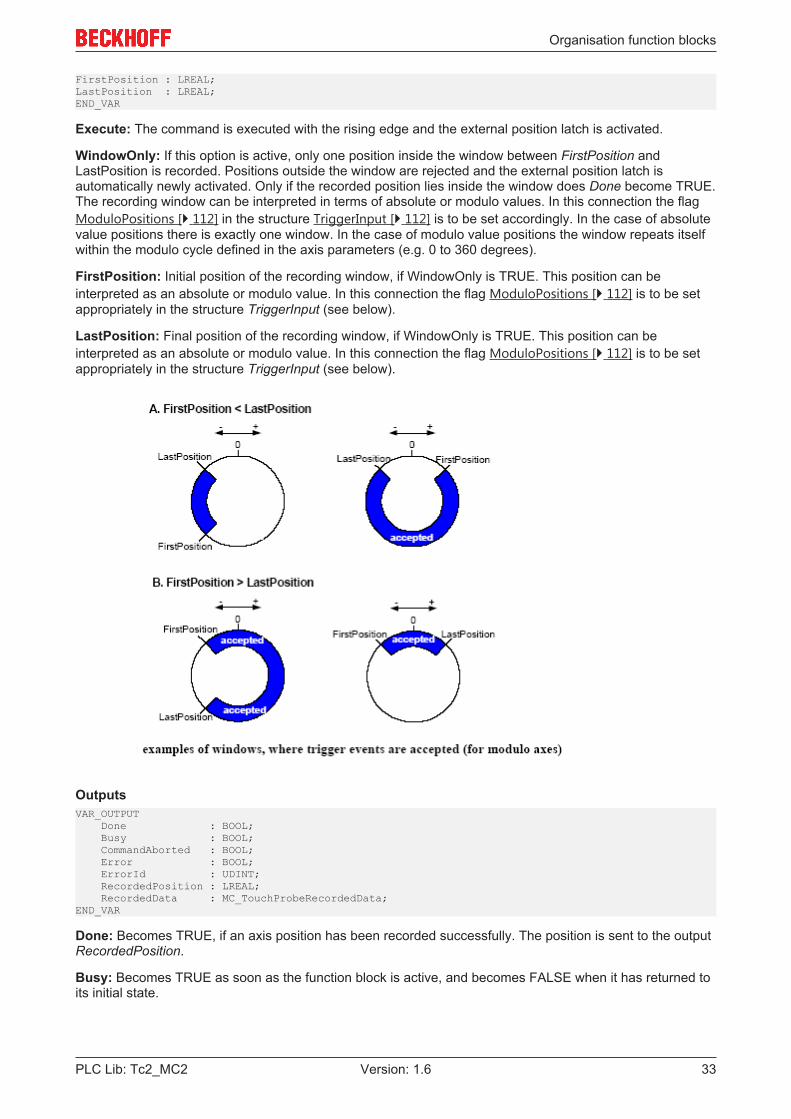
WindowOnly: If this option is active, only one position inside the window between FirstPosition andLastPosition is recorded. Positions outside the window are rejected and the external position latch isautomatically newly activated. Only if the recorded position lies inside the window does Done become TRUE.The recording window can be interpreted in terms of absolute or modulo values. In this connection the flagModuloPositions [} 112] in the structure TriggerInput [} 112] is to be set accordingly. In the case of absolutevalue positions there is exactly one window. In the case of modulo value positions the window repeats itselfwithin the modulo cycle defined in the axis parameters (e.g. 0 to 360 degrees).
FirstPosition: Initial position of the recording window, if WindowOnly is TRUE. This position can beinterpreted as an absolute or modulo value. In this connection the flag ModuloPositions [} 112] is to be setappropriately in the structure TriggerInput (see below).
LastPosition: Final position of the recording window, if WindowOnly is TRUE. This position can beinterpreted as an absolute or modulo value. In this connection the flag ModuloPositions [} 112] is to be setappropriately in the structure TriggerInput (see below).
OutputsVAR_OUTPUT Done : BOOL; Busy : BOOL; CommandAborted : BOOL; Error : BOOL; ErrorId : UDINT; RecordedPosition : LREAL; RecordedData : MC_TouchProbeRecordedData; END_VAR
Done: Becomes TRUE, if an axis position has been recorded successfully. The position is sent to the outputRecordedPosition.
Busy: Becomes TRUE as soon as the function block is active, and becomes FALSE when it has returned toits initial state.
Organisation function blocks
PLC Lib: Tc2_MC234 Version: 1.6
CommandAborted: Becomes TRUE if the process is interrupted by an external event, e.g. by the call up ofMC_AbortTrigger [} 34].
Error: Becomes TRUE, as soon as an error occurs.
ErrorID: If the error output is set, this parameter supplies the error number.
RecordedPosition: Axis position recorded at the point in time of the trigger signal
RecordedData: Data structure with complementary information relating to the logged axis position at thetime of the trigger signal
Inputs/outputsVAR_IN_OUT Axis : AXIS_REF; TriggerInput : TRIGGER_REF; END_VAR
Axis: Axis data structure [} 91]
TriggerInput: Data structure [} 112]for describing the trigger source. This data structure must beparameterized before the function block is called for the first time.
Requirements
Development environment Target system type PLC libraries to includeTwinCAT v3.0.0 PC or CX (x86) Tc2_MC2
5.3.2 MC_AbortTrigger
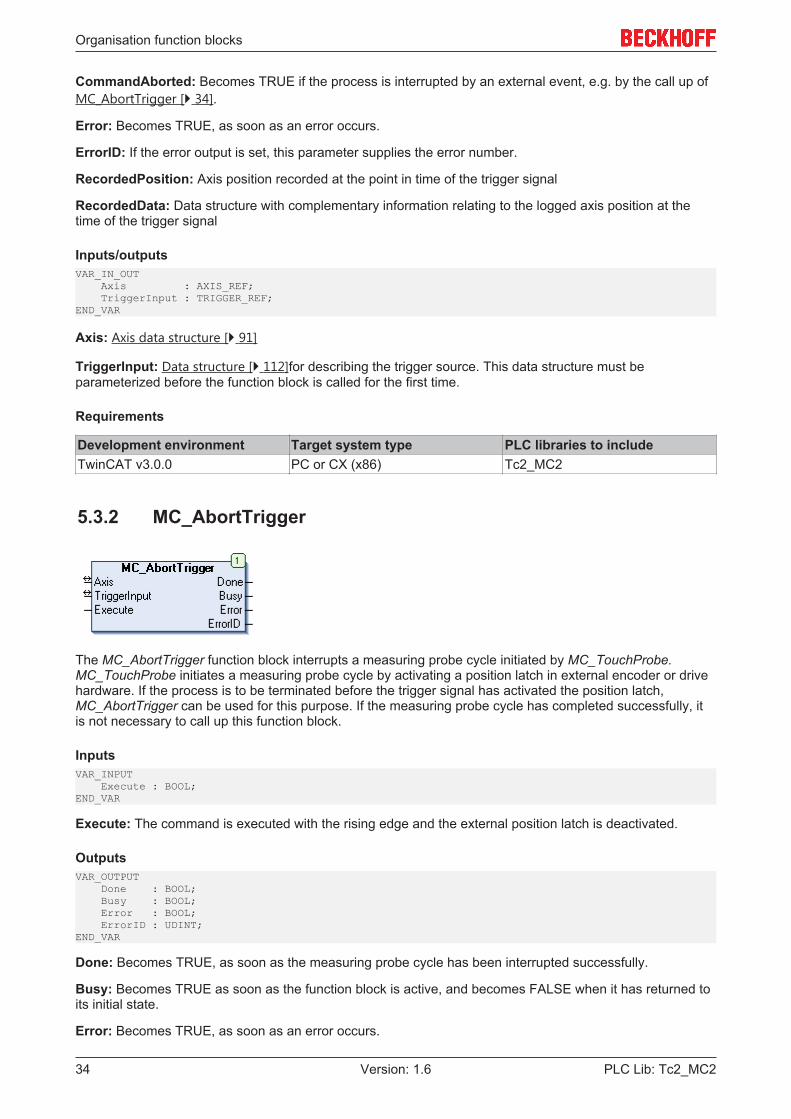
The MC_AbortTrigger function block interrupts a measuring probe cycle initiated by MC_TouchProbe.MC_TouchProbe initiates a measuring probe cycle by activating a position latch in external encoder or drivehardware. If the process is to be terminated before the trigger signal has activated the position latch,MC_AbortTrigger can be used for this purpose. If the measuring probe cycle has completed successfully, itis not necessary to call up this function block.
InputsVAR_INPUT Execute : BOOL;END_VAR
Execute: The command is executed with the rising edge and the external position latch is deactivated.
OutputsVAR_OUTPUT Done : BOOL; Busy : BOOL; Error : BOOL; ErrorID : UDINT;END_VAR
Done: Becomes TRUE, as soon as the measuring probe cycle has been interrupted successfully.
Busy: Becomes TRUE as soon as the function block is active, and becomes FALSE when it has returned toits initial state.
Error: Becomes TRUE, as soon as an error occurs.
Organisation function blocks
PLC Lib: Tc2_MC2 35Version: 1.6
ErrorID: If the error output is set, this parameter supplies the error number.
Inputs/outputsVAR_IN_OUT Axis : AXIS_REF; TriggerInput : TRIGGER_REF; END_VAR
Axis: Axis data structure [} 91]
TriggerInput: Data structure [} 112]for describing the trigger source. This data structure must beparameterized before the function block is called for the first time.
Requirements
Development environment Target system type PLC libraries to includeTwinCAT v3.0.0 PC or CX (x86) Tc2_MC2
5.4 External set value generator
5.4.1 MC_ExtSetPointGenEnable
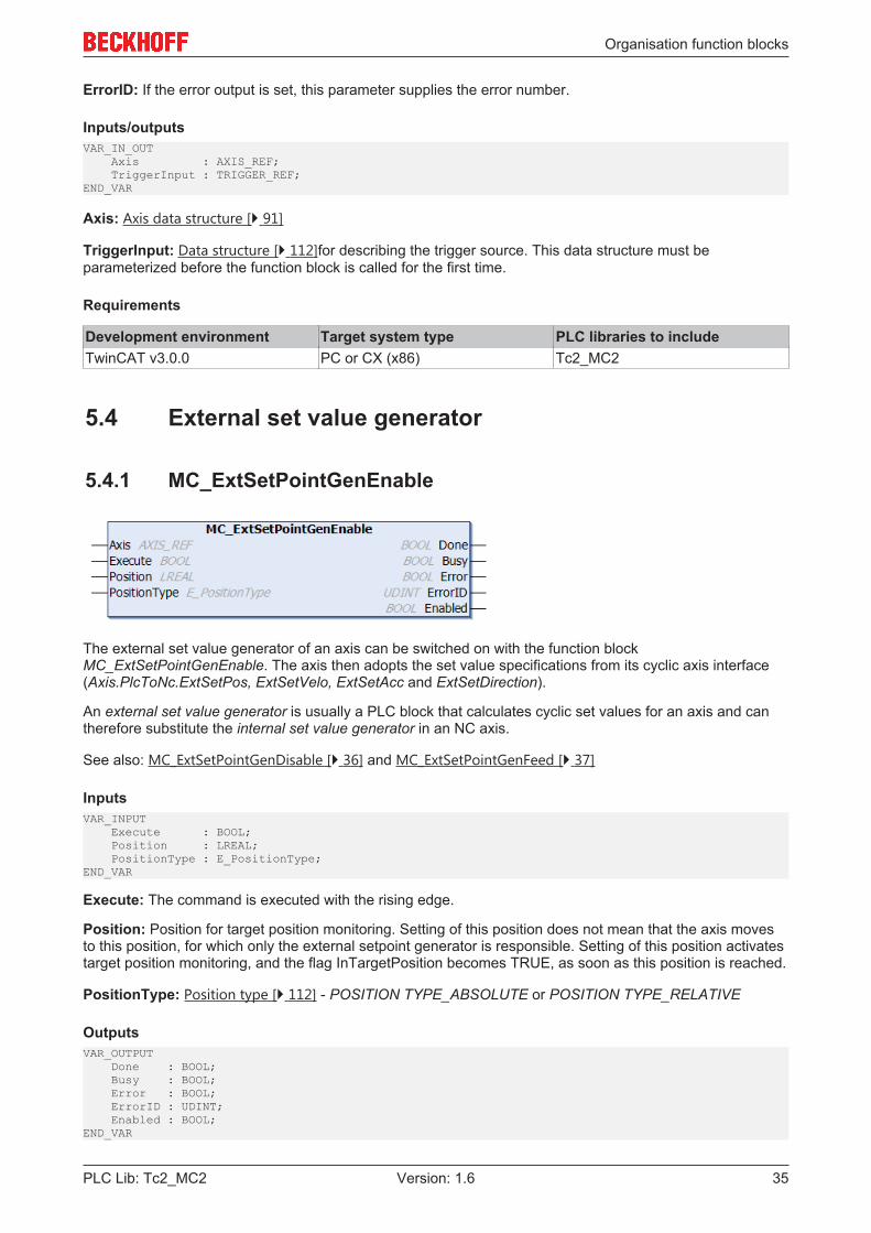
The external set value generator of an axis can be switched on with the function blockMC_ExtSetPointGenEnable. The axis then adopts the set value specifications from its cyclic axis interface(Axis.PlcToNc.ExtSetPos, ExtSetVelo, ExtSetAcc and ExtSetDirection).
An external set value generator is usually a PLC block that calculates cyclic set values for an axis and cantherefore substitute the internal set value generator in an NC axis.
See also: MC_ExtSetPointGenDisable [} 36] and MC_ExtSetPointGenFeed [} 37]
InputsVAR_INPUT Execute : BOOL; Position : LREAL; PositionType : E_PositionType;END_VAR
Execute: The command is executed with the rising edge.
Position: Position for target position monitoring. Setting of this position does not mean that the axis movesto this position, for which only the external setpoint generator is responsible. Setting of this position activatestarget position monitoring, and the flag InTargetPosition becomes TRUE, as soon as this position is reached.
PositionType: Position type [} 112] - POSITION TYPE_ABSOLUTE or POSITION TYPE_RELATIVE
OutputsVAR_OUTPUT Done : BOOL; Busy : BOOL; Error : BOOL; ErrorID : UDINT; Enabled : BOOL;END_VAR
Organisation function blocks
PLC Lib: Tc2_MC236 Version: 1.6
Done: Becomes TRUE, if the command was executed successfully.
Busy: Becomes TRUE as soon as the function block is active, and becomes FALSE when it has returned toits initial state.
Error: Becomes TRUE, as soon as an error occurs.
ErrorID: If the error output is set, this parameter supplies the error number.
Enabled: Enabled shows the current state of the external setpoint generator, independent of the functionexecution.
Inputs/outputsVAR_IN_OUT Axis : AXIS_REF;END_VAR
Axis: Axis data structure of the type AXIS_REF [} 91], which uniquely addresses an axis in the system.Among other parameters it contains the current axis status, including position, velocity or error status.
Requirements
Development environment Target system type PLC libraries to includeTwinCAT v3.0.0 PC or CX (x86) Tc2_MC2
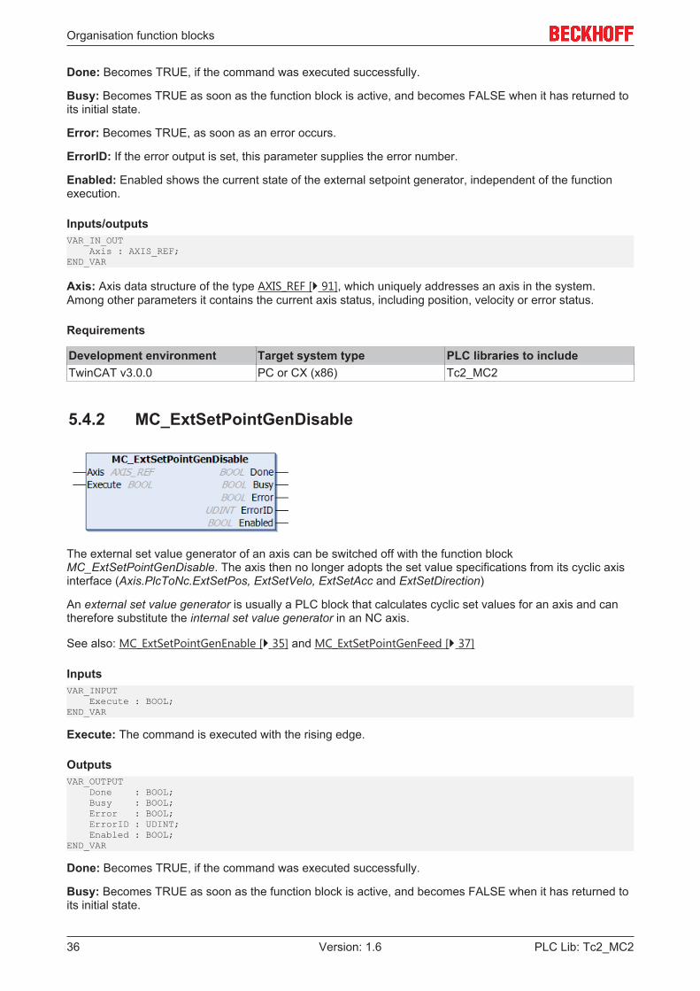
5.4.2 MC_ExtSetPointGenDisable
The external set value generator of an axis can be switched off with the function blockMC_ExtSetPointGenDisable. The axis then no longer adopts the set value specifications from its cyclic axisinterface (Axis.PlcToNc.ExtSetPos, ExtSetVelo, ExtSetAcc and ExtSetDirection)
An external set value generator is usually a PLC block that calculates cyclic set values for an axis and cantherefore substitute the internal set value generator in an NC axis.
See also: MC_ExtSetPointGenEnable [} 35] and MC_ExtSetPointGenFeed [} 37]
InputsVAR_INPUT Execute : BOOL;END_VAR
Execute: The command is executed with the rising edge.
OutputsVAR_OUTPUT Done : BOOL; Busy : BOOL; Error : BOOL; ErrorID : UDINT; Enabled : BOOL;END_VAR
Done: Becomes TRUE, if the command was executed successfully.
Busy: Becomes TRUE as soon as the function block is active, and becomes FALSE when it has returned toits initial state.
Organisation function blocks
PLC Lib: Tc2_MC2 37Version: 1.6
Error: Becomes TRUE, as soon as an error occurs.
ErrorID: If the error output is set, this parameter supplies the error number.
Enabled: Enabled shows the current state of the external setpoint generator, independent of the functionexecution.
Inputs/outputsVAR_IN_OUT Axis : AXIS_REF;END_VAR
Axis: Axis data structure of the type AXIS_REF [} 91], which uniquely addresses an axis in the system.Among other parameters it contains the current axis status, including position, velocity or error status.
Requirements
Development environment Target system type PLC libraries to includeTwinCAT v3.0.0 PC or CX (x86) Tc2_MC2
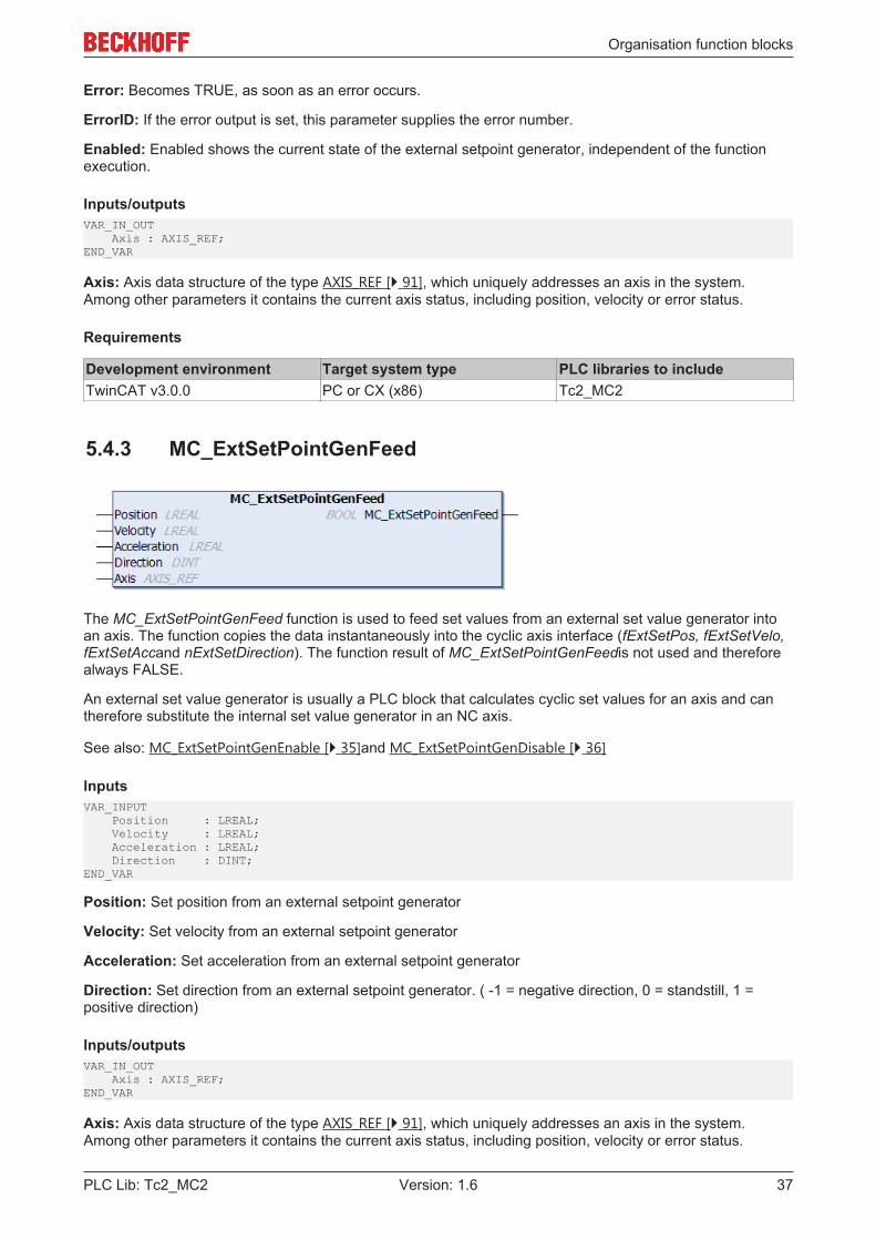
5.4.3 MC_ExtSetPointGenFeed
The MC_ExtSetPointGenFeed function is used to feed set values from an external set value generator intoan axis. The function copies the data instantaneously into the cyclic axis interface (fExtSetPos, fExtSetVelo,fExtSetAccand nExtSetDirection). The function result of MC_ExtSetPointGenFeedis not used and thereforealways FALSE.
An external set value generator is usually a PLC block that calculates cyclic set values for an axis and cantherefore substitute the internal set value generator in an NC axis.
See also: MC_ExtSetPointGenEnable [} 35]and MC_ExtSetPointGenDisable [} 36]
InputsVAR_INPUT Position : LREAL; Velocity : LREAL; Acceleration : LREAL; Direction : DINT;END_VAR
Position: Set position from an external setpoint generator
Velocity: Set velocity from an external setpoint generator
Acceleration: Set acceleration from an external setpoint generator
Direction: Set direction from an external setpoint generator. ( -1 = negative direction, 0 = standstill, 1 =positive direction)
Inputs/outputsVAR_IN_OUT Axis : AXIS_REF;END_VAR
Axis: Axis data structure of the type AXIS_REF [} 91], which uniquely addresses an axis in the system.Among other parameters it contains the current axis status, including position, velocity or error status.
Organisation function blocks
PLC Lib: Tc2_MC238 Version: 1.6
Requirements
Development environment Target system type PLC libraries to includeTwinCAT v3.0.0 PC or CX (x86) Tc2_MC2
5.5 Special extensions
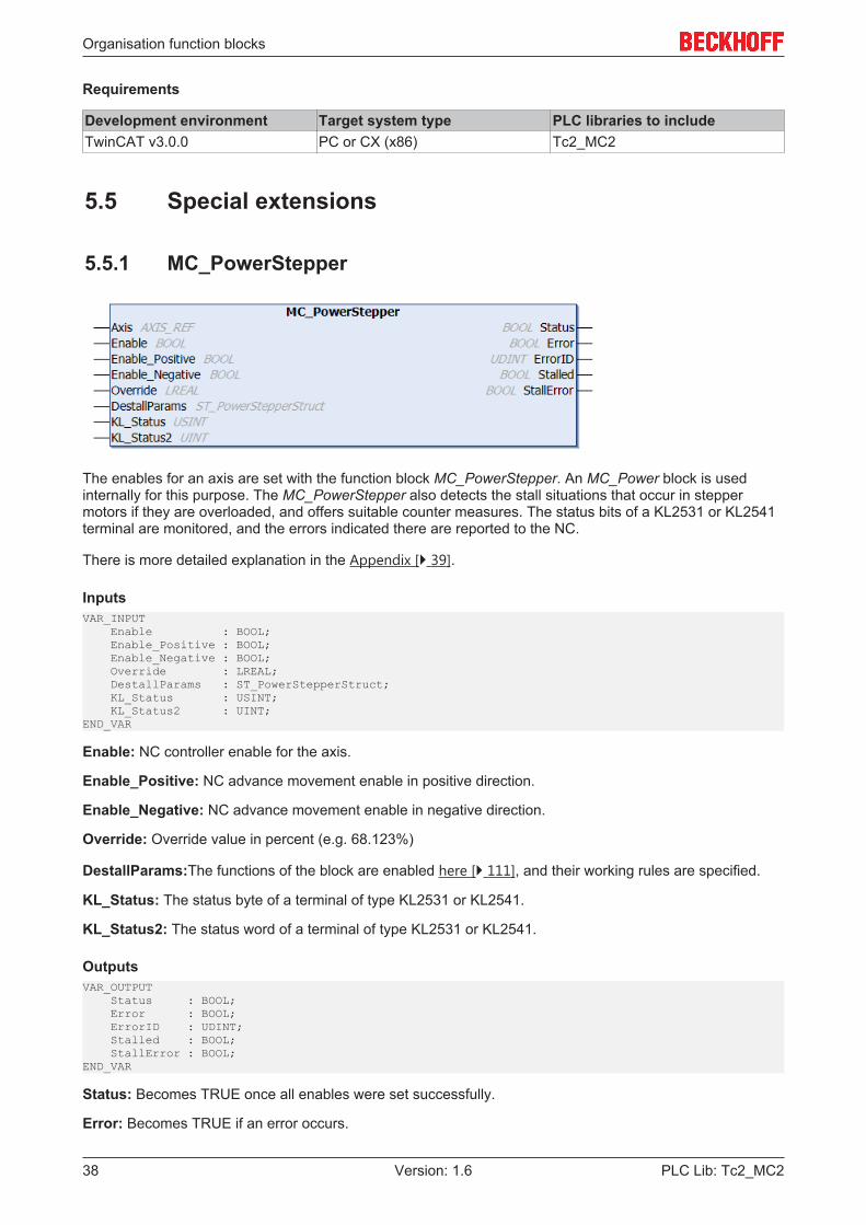
5.5.1 MC_PowerStepper
The enables for an axis are set with the function block MC_PowerStepper. An MC_Power block is usedinternally for this purpose. The MC_PowerStepper also detects the stall situations that occur in steppermotors if they are overloaded, and offers suitable counter measures. The status bits of a KL2531 or KL2541terminal are monitored, and the errors indicated there are reported to the NC.
There is more detailed explanation in the Appendix [} 39].
InputsVAR_INPUT Enable : BOOL; Enable_Positive : BOOL; Enable_Negative : BOOL; Override : LREAL; DestallParams : ST_PowerStepperStruct; KL_Status : USINT; KL_Status2 : UINT;END_VAR
Enable: NC controller enable for the axis.
Enable_Positive: NC advance movement enable in positive direction.
Enable_Negative: NC advance movement enable in negative direction.
Override: Override value in percent (e.g. 68.123%)
DestallParams:The functions of the block are enabled here [} 111], and their working rules are specified.
KL_Status: The status byte of a terminal of type KL2531 or KL2541.
KL_Status2: The status word of a terminal of type KL2531 or KL2541.
OutputsVAR_OUTPUT Status : BOOL; Error : BOOL; ErrorID : UDINT; Stalled : BOOL; StallError : BOOL;END_VAR
Status: Becomes TRUE once all enables were set successfully.
Error: Becomes TRUE if an error occurs.
Organisation function blocks
PLC Lib: Tc2_MC2 39Version: 1.6
ErrorID: If the error output is set, this parameter supplies the error number.
Stalled: no description
StallError: no description
Inputs/outputsVAR_IN_OUT Axis : AXIS_REF;END_VAR
Axis: Axis data structure of the type AXIS_REF [} 91], which uniquely addresses an axis in the system.Among other parameters it contains the current axis status, including position, velocity or error status.
Requirements
Development environment Target system type PLC libraries to includeTwinCAT v3.0.0 PC or CX (x86) Tc2_MC2
5.5.2 Notes on the MC_PowerStepperThe enables and the override for an axis are set with the MC_PowerStepper [} 38] function block. AnMC_Power [} 16] block is used internally for this purpose. The MC_PowerStepper also detects the stallsituations that occur in stepper motors if they are overloaded, and offers suitable counter measures. Thestatus bits of a KL2531 or KL2541 terminal are monitored, and the errors indicated there are reported to theNC.
Stepper motor and synchronous servo: similarities and differences
Both types of motor use an electromagnetic field and the field of a permanent magnet in order to generate adriving force through their interaction. Whereas, however, the servomotor makes use of an expensivesystem of sensors in order to make specific adjustments to the alignments of the fields (current supplieddependent on the rotor position), this position-dependent control is not used for the stepper motor. Thismakes it possible to save considerable costs. There is, however, a possibility that some external force willpush the motor beyond the position where it is able to generate the maximum torque. Because theelectrically generated magnetic field does not take this into account, the restoring torque generated will fallas the excursion increases. As a result of this, if the excursion is more than the one half of one pole stepthen the corrective torque will change sign, pushing the motor on in the direction of the next pole position.Depending on the conditions that now apply, the motor may now latch into the new position (which meansthat a complete step has been lost), or the whole process may be repeated again here. The latter case isreferred to as stalling, and is most likely to occur when current is fed to the motor at the typical frequency ofthe active drive operation.
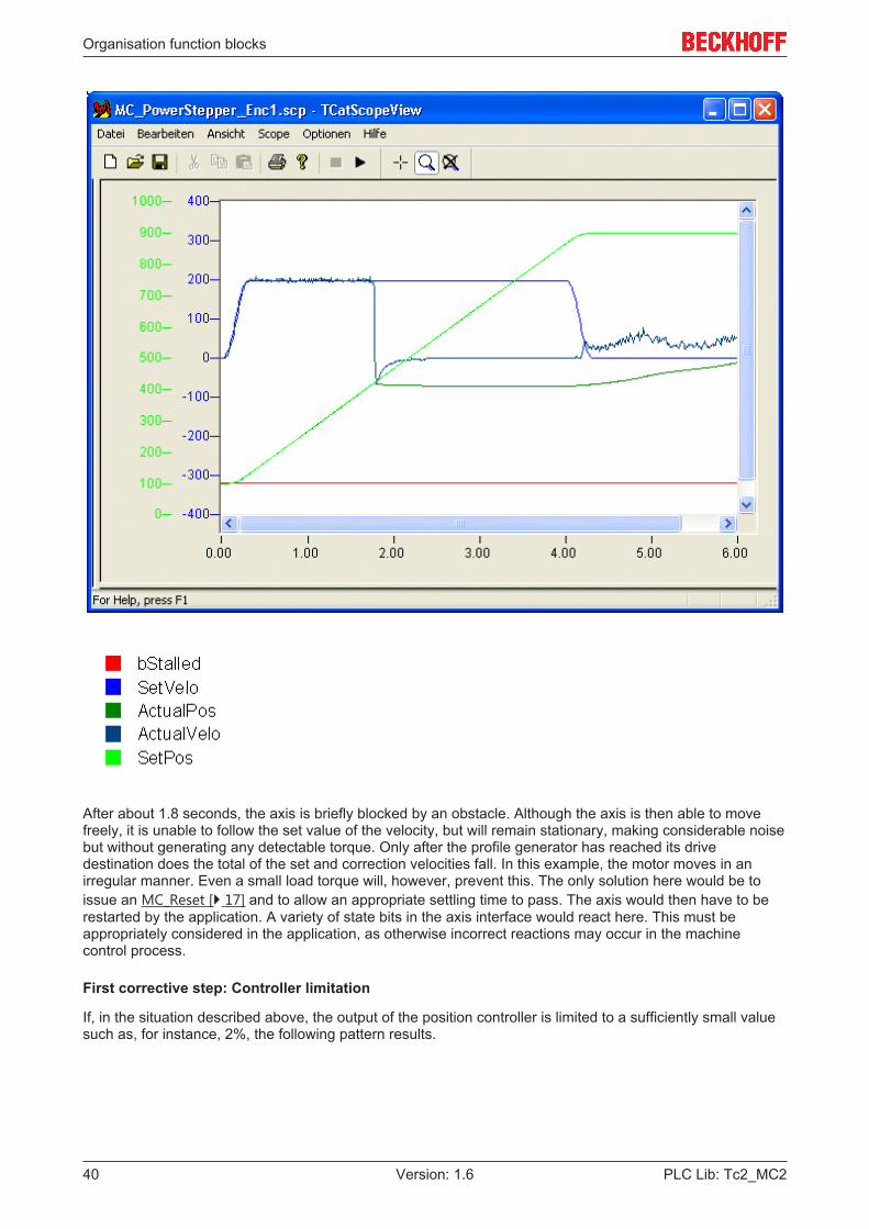
Example 1: A stepper motor fitted with an encoder is operated with the NC PTP using the parameters typicalfor servos.
Organisation function blocks
PLC Lib: Tc2_MC240 Version: 1.6
After about 1.8 seconds, the axis is briefly blocked by an obstacle. Although the axis is then able to movefreely, it is unable to follow the set value of the velocity, but will remain stationary, making considerable noisebut without generating any detectable torque. Only after the profile generator has reached its drivedestination does the total of the set and correction velocities fall. In this example, the motor moves in anirregular manner. Even a small load torque will, however, prevent this. The only solution here would be toissue an MC_Reset [} 17] and to allow an appropriate settling time to pass. The axis would then have to berestarted by the application. A variety of state bits in the axis interface would react here. This must beappropriately considered in the application, as otherwise incorrect reactions may occur in the machinecontrol process.
First corrective step: Controller limitation
If, in the situation described above, the output of the position controller is limited to a sufficiently small valuesuch as, for instance, 2%, the following pattern results.
Organisation function blocks
PLC Lib: Tc2_MC2 41Version: 1.6
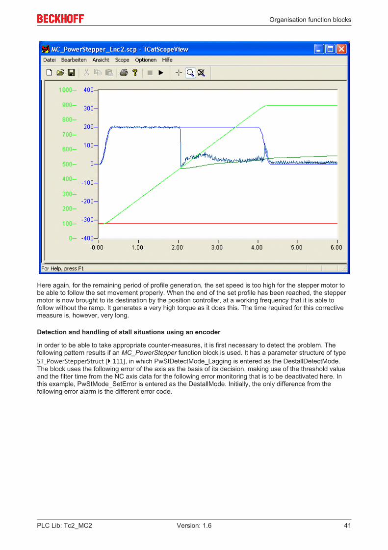
Here again, for the remaining period of profile generation, the set speed is too high for the stepper motor tobe able to follow the set movement properly. When the end of the set profile has been reached, the steppermotor is now brought to its destination by the position controller, at a working frequency that it is able tofollow without the ramp. It generates a very high torque as it does this. The time required for this correctivemeasure is, however, very long.
Detection and handling of stall situations using an encoder
In order to be able to take appropriate counter-measures, it is first necessary to detect the problem. Thefollowing pattern results if an MC_PowerStepper function block is used. It has a parameter structure of typeST_PowerStepperStruct [} 111], in which PwStDetectMode_Lagging is entered as the DestallDetectMode.The block uses the following error of the axis as the basis of its decision, making use of the threshold valueand the filter time from the NC axis data for the following error monitoring that is to be deactivated here. Inthis example, PwStMode_SetError is entered as the DestallMode. Initially, the only difference from thefollowing error alarm is the different error code.
Organisation function blocks
PLC Lib: Tc2_MC242 Version: 1.6
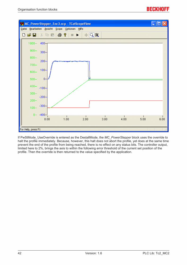
If PwStMode_UseOverride is entered as the DestallMode, the MC_PowerStepper block uses the override tohalt the profile immediately. Because, however, this halt does not abort the profile, yet does at the same timeprevent the end of the profile from being reached, there is no effect on any status bits. The controller output,limited here to 2%, brings the axis to within the following error threshold of the current set position of theprofile. Then the override is then returned to the value specified by the application.
Organisation function blocks
PLC Lib: Tc2_MC2 43Version: 1.6
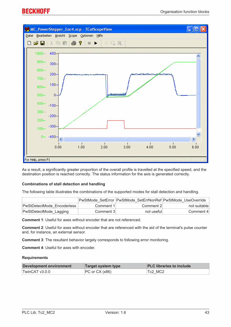
As a result, a significantly greater proportion of the overall profile is travelled at the specified speed, and thedestination position is reached correctly. The status information for the axis is generated correctly.
Combinations of stall detection and handling
The following table illustrates the combinations of the supported modes for stall detection and handling.
PwStMode_SetError PwStMode_SetErrNonRef PwStMode_UseOverridePwStDetectMode_Encoderless Comment 1 Comment 2 not suitablePwStDetectMode_Lagging Comment 3 not useful Comment 4
Comment 1: Useful for axes without encoder that are not referenced.
Comment 2: Useful for axes without encoder that are referenced with the aid of the terminal's pulse counterand, for instance, an external sensor.
Comment 3: The resultant behavior largely corresponds to following error monitoring.
Comment 4: Useful for axes with encoder.
Requirements
Development environment Target system type PLC libraries to includeTwinCAT v3.0.0 PC or CX (x86) Tc2_MC2

Organisation function blocks
PLC Lib: Tc2_MC244 Version: 1.6
5.5.3 MC_OverrideFilter
The function block MC_OverrideFilter can be used to convert an unfiltered override value consisting of digits(e.g. a voltage value of an analog input terminal) into a filtered override value that matches the cyclic axisinterface (PlcToNc) (DWORD in the range 0 to 1000000). This filtered override is also available in percent(LREAL in the range 0 to 100%).The raw input value is limited to a validity range by LowerOverrideThreshold andUpperOverrideThresholdauf, and implemented as parameterizable steps (resolution) (OverrideSteps). Aftereach override change at the output of the FB, a minimum recovery time is awaited internally(OverrideRecoveryTime) before a new override value can be accepted. The only exceptions are the overridevalues 0% and 100%, which are always implemented without delay for safety reasons.
Note
Due to the stepping of the override output value (OverrideValueFiltered), the filtered over-ride may become zero for very small override input values (OverrideValueRaw). A zerooverride leads to standstill of the axis. If total standstill is undesired, OverrideValueRawshould not fall below the smallest level.
InputsVAR_INPUT OverrideValueRaw : DINT; LowerOverrideThreshold : DINT := 0; (* 0...32767 digits *) UpperOverrideThreshold : DINT := 32767; (* 0...32767 digits *) OverrideSteps : UDINT := 200; (* 200 steps => 0.5 percent *) OverrideRecoveryTime : TIME := T#150ms; (* 150 ms *)END_VAR
OverrideValueRaw: Raw, unfiltered override value (e.g. a voltage value of an analog input terminal).
LowerOverrideThreshold: The lower threshold for the raw override value.
UpperOverrideThreshold: The upper threshold for the raw override value.
OverrideSteps: The specified steps (override resolution).
OverrideRecoveryTime: Minimum recovery time, after which a new filtered override value is placed on theoutput. The override values 0% and 100% are implemented without delay.
OutputsVAR_OUTPUT OverrideValueFiltered : DWORD; (* 0...1000000 counts *) OverridePercentFiltered : LREAL; (* 0...100 % *) Error : BOOL; ErrorId : UDINT;END_VAR
OverrideValueFiltered: The filtered override value in digits (the data type matches the override in the cyclicaxis interface 0 to 1000000).
OverridePercentFiltered: The filtered override value in percent (0 to 100%).
Error: Becomes TRUE if an error occurs.
ErrorID: If the error output is set, this parameter supplies the error number.
Possible error number Possible causesMC_ERROR_PARAMETER_NOT_CORRECT • OverrideSteps <= 1
• LowerOverrideThreshold >=UpperOverrideThreshold
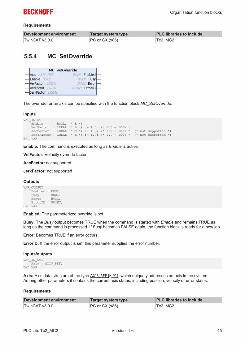
Organisation function blocks
PLC Lib: Tc2_MC2 45Version: 1.6
Requirements
Development environment Target system type PLC libraries to includeTwinCAT v3.0.0 PC or CX (x86) Tc2_MC2
5.5.4 MC_SetOverride
The override for an axis can be specified with the function block MC_SetOverride.
InputsVAR_INPUT Enable : BOOL; (* B *) VelFactor : LREAL (* B *) := 1.0; (* 1.0 = 100% *) AccFactor : LREAL (* E *) := 1.0; (* 1.0 = 100% *) (* not supported *) JerkFactor : LREAL (* E *) := 1.0; (* 1.0 = 100% *) (* not supported *)END_VAR
Enable: The command is executed as long as Enable is active.
VelFactor: Velocity override factor
AccFactor: not supported
JerkFactor: not supported
OutputsVAR_OUTPUT Enabled : BOOL; Busy : BOOL; Error : BOOL; ErrorID : UDINT;END_VAR
Enabled: The parameterized override is set
Busy: The Busy output becomes TRUE when the command is started with Enable and remains TRUE aslong as the command is processed. If Busy becomes FALSE again, the function block is ready for a new job.
Error: Becomes TRUE if an error occurs.
ErrorID: If the error output is set, this parameter supplies the error number.
Inputs/outputsVAR_IN_OUT Axis : AXIS_REF;END_VAR
Axis: Axis data structure of the type AXIS_REF [} 91], which uniquely addresses an axis in the system.Among other parameters it contains the current axis status, including position, velocity or error status.
Requirements
Development environment Target system type PLC libraries to includeTwinCAT v3.0.0 PC or CX (x86) Tc2_MC2

Organisation function blocks
PLC Lib: Tc2_MC246 Version: 1.6
5.5.5 MC_SetEncoderScalingFactor
MC_SetEncoderScalingFactor changes the scaling factor for the active encoder of an axis, either at standstillor in motion.
The change can be absolute or relative. This mode is only suitable at standstill, since in absolute mode thechange in scaling factor leads to a position discontinuity. In relative mode an internal position offset isadapted at the same time such that no discontinuity occurs. Please note that intervention during motionchanges the actual velocity of the axis while the real velocity remains constant. Therefore only smallchanges can be implemented during the motion.
InputsVAR_INPUT Execute : BOOL; ScalingFactor : LREAL; Mode : E_SetScalingFactorMode; Options : ST_SetEncoderScalingOptions; END_VAR
Execute: The command is executed with a rising edge at input Execute.
ScalingFactor: Scaling factor of the active encoder of an axis. The scaling factor is specified in physicalpositioning units [u] divided by the number of encoder increments.
Mode: The scaling factor can be set in absolute or relative mode (ENCODERSCALINGMODE_ABSOLUTE,ENCODERSCALINGMODE_RELATIVE).In absolute mode counting starts at the origin of the axis coordinate system, resulting in a positiondiscontinuity if the scaling factor is changed. In relative mode the actual position of the axis does not change.This mode is therefore also suitable for changes during motion.
Options: The data structure option includes additional, rarely required parameters. The input can normallyremain open.
• SelectEncoderIndex: SelectEncoderIndex can optionally be set if an axis with several encoders isused and the position of a certain encoder is to be set (Options.EncoderIndex).
• EncoderIndex: EncoderIndex indicates the encoder (0 to n) if SelectEncoderIndex is TRUE.
General rules for MC function blocks [} 13]
OutputsVAR_OUTPUT Done : BOOL; Busy : BOOL; Error : BOOL; ErrorID : UDINT;END_VAR
Done: The Done output becomes TRUE, once the position was set successfully.
Busy: The Busy output becomes TRUE when the command is started with Execute and remains TRUE aslong as the command is processed. If Busy becomes FALSE again, the function block is ready for a new job.At the same time one of the outputs, Done or Error, is set.
Error: Becomes TRUE if an error occurs.
ErrorID: If the error output is set, this parameter supplies the error number.
General rules for MC function blocks [} 13]
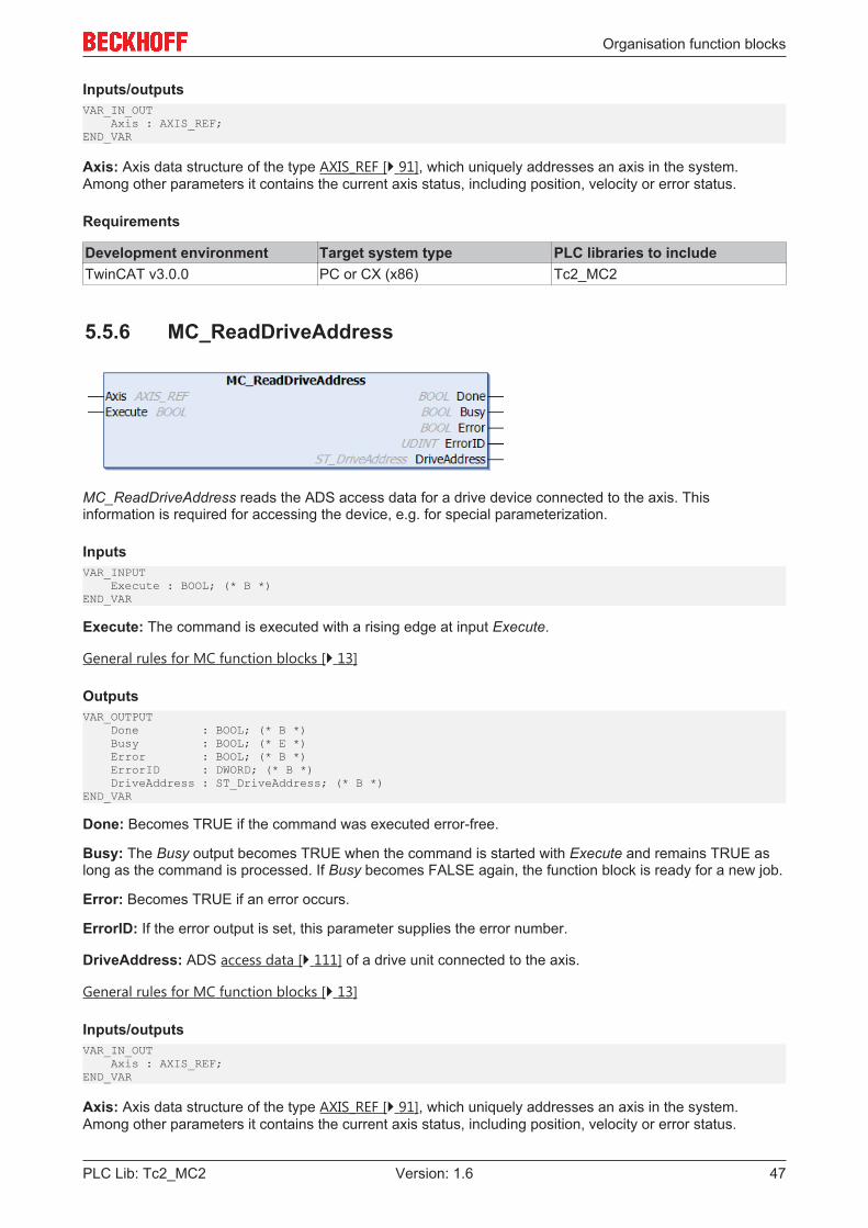
Organisation function blocks
PLC Lib: Tc2_MC2 47Version: 1.6
Inputs/outputsVAR_IN_OUT Axis : AXIS_REF;END_VAR
Axis: Axis data structure of the type AXIS_REF [} 91], which uniquely addresses an axis in the system.Among other parameters it contains the current axis status, including position, velocity or error status.
Requirements
Development environment Target system type PLC libraries to includeTwinCAT v3.0.0 PC or CX (x86) Tc2_MC2
5.5.6 MC_ReadDriveAddress
MC_ReadDriveAddress reads the ADS access data for a drive device connected to the axis. Thisinformation is required for accessing the device, e.g. for special parameterization.
InputsVAR_INPUT Execute : BOOL; (* B *)END_VAR
Execute: The command is executed with a rising edge at input Execute.
General rules for MC function blocks [} 13]
OutputsVAR_OUTPUT Done : BOOL; (* B *) Busy : BOOL; (* E *) Error : BOOL; (* B *) ErrorID : DWORD; (* B *) DriveAddress : ST_DriveAddress; (* B *)END_VAR
Done: Becomes TRUE if the command was executed error-free.
Busy: The Busy output becomes TRUE when the command is started with Execute and remains TRUE aslong as the command is processed. If Busy becomes FALSE again, the function block is ready for a new job.
Error: Becomes TRUE if an error occurs.
ErrorID: If the error output is set, this parameter supplies the error number.
DriveAddress: ADS access data [} 111] of a drive unit connected to the axis.
General rules for MC function blocks [} 13]
Inputs/outputsVAR_IN_OUT Axis : AXIS_REF;END_VAR
Axis: Axis data structure of the type AXIS_REF [} 91], which uniquely addresses an axis in the system.Among other parameters it contains the current axis status, including position, velocity or error status.
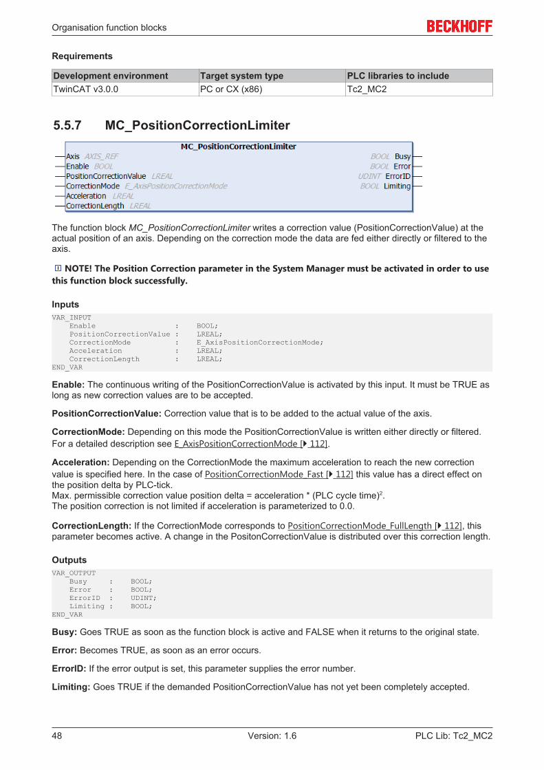
Organisation function blocks
PLC Lib: Tc2_MC248 Version: 1.6
Requirements
Development environment Target system type PLC libraries to includeTwinCAT v3.0.0 PC or CX (x86) Tc2_MC2
5.5.7 MC_PositionCorrectionLimiter
The function block MC_PositionCorrectionLimiter writes a correction value (PositionCorrectionValue) at theactual position of an axis. Depending on the correction mode the data are fed either directly or filtered to theaxis.
NOTE! The Position Correction parameter in the System Manager must be activated in order to usethis function block successfully.
InputsVAR_INPUT Enable : BOOL; PositionCorrectionValue : LREAL; CorrectionMode : E_AxisPositionCorrectionMode; Acceleration : LREAL; CorrectionLength : LREAL;END_VAR
Enable: The continuous writing of the PositionCorrectionValue is activated by this input. It must be TRUE aslong as new correction values are to be accepted.
PositionCorrectionValue: Correction value that is to be added to the actual value of the axis.
CorrectionMode: Depending on this mode the PositionCorrectionValue is written either directly or filtered.For a detailed description see E_AxisPositionCorrectionMode [} 112].
Acceleration: Depending on the CorrectionMode the maximum acceleration to reach the new correctionvalue is specified here. In the case of PositionCorrectionMode_Fast [} 112] this value has a direct effect onthe position delta by PLC-tick.Max. permissible correction value position delta = acceleration * (PLC cycle time)2.The position correction is not limited if acceleration is parameterized to 0.0.
CorrectionLength: If the CorrectionMode corresponds to PositionCorrectionMode_FullLength [} 112], thisparameter becomes active. A change in the PositonCorrectionValue is distributed over this correction length.
OutputsVAR_OUTPUT Busy : BOOL; Error : BOOL; ErrorID : UDINT; Limiting : BOOL;END_VAR
Busy: Goes TRUE as soon as the function block is active and FALSE when it returns to the original state.
Error: Becomes TRUE, as soon as an error occurs.
ErrorID: If the error output is set, this parameter supplies the error number.
Limiting: Goes TRUE if the demanded PositionCorrectionValue has not yet been completely accepted.
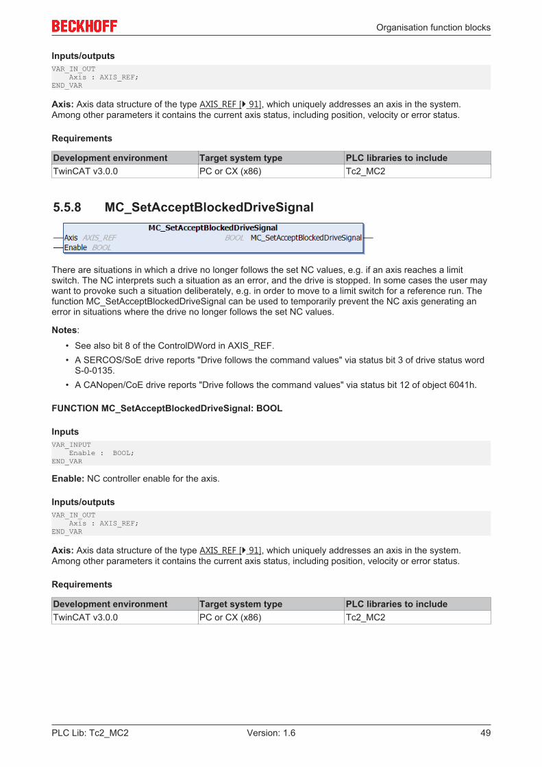
Organisation function blocks
PLC Lib: Tc2_MC2 49Version: 1.6
Inputs/outputsVAR_IN_OUT Axis : AXIS_REF;END_VAR
Axis: Axis data structure of the type AXIS_REF [} 91], which uniquely addresses an axis in the system.Among other parameters it contains the current axis status, including position, velocity or error status.
Requirements
Development environment Target system type PLC libraries to includeTwinCAT v3.0.0 PC or CX (x86) Tc2_MC2
5.5.8 MC_SetAcceptBlockedDriveSignal
There are situations in which a drive no longer follows the set NC values, e.g. if an axis reaches a limitswitch. The NC interprets such a situation as an error, and the drive is stopped. In some cases the user maywant to provoke such a situation deliberately, e.g. in order to move to a limit switch for a reference run. Thefunction MC_SetAcceptBlockedDriveSignal can be used to temporarily prevent the NC axis generating anerror in situations where the drive no longer follows the set NC values.
Notes:
• See also bit 8 of the ControlDWord in AXIS_REF.• A SERCOS/SoE drive reports "Drive follows the command values" via status bit 3 of drive status word
S-0-0135.• A CANopen/CoE drive reports "Drive follows the command values" via status bit 12 of object 6041h.
FUNCTION MC_SetAcceptBlockedDriveSignal: BOOL
InputsVAR_INPUT Enable : BOOL;END_VAR
Enable: NC controller enable for the axis.
Inputs/outputsVAR_IN_OUT Axis : AXIS_REF;END_VAR
Axis: Axis data structure of the type AXIS_REF [} 91], which uniquely addresses an axis in the system.Among other parameters it contains the current axis status, including position, velocity or error status.
Requirements
Development environment Target system type PLC libraries to includeTwinCAT v3.0.0 PC or CX (x86) Tc2_MC2

Motion function blocks
PLC Lib: Tc2_MC250 Version: 1.6
6 Motion function blocks
6.1 Point to point motion
6.1.1 MC_MoveAbsolute
MC_MoveAbsolute starts positioning to an absolute target position and monitors the axis movement over thewhole travel path. The Done output is set once the target position has been reached. Otherwise theCommandAborted or, on error, the Error output is set.
MC_MoveAbsolute is predominantly used for linear axis systems. For modulo axes the position is notinterpreted as a modulo position, but as an absolute position in continuous absolute coordinate system.Alternatively, the MC_MoveModulo [} 55] block can be used for modulo positioning.
Motion commands can be applied to coupled slave axes, if this option was explicitly activated in the axisparameters. A motion command such as MC_MoveAbsolute then automatically leads to uncoupling of theaxis, after which the command is executed. In this case only Buffer-ModeAborting is possible.
InputsVAR_INPUT Execute : BOOL; Position : LREAL; Velocity : LREAL; Acceleration : LREAL; Deceleration : LREAL; Jerk : LREAL; BufferMode : MC_BufferMode; Options : ST_MoveOptions;END_VAR
Execute: The command is executed with a rising edge at input Execute.
Position: Absolute target position to be used for positioning.
Velocity: Maximum travel velocity (>0).
Acceleration: Acceleration (≥0). If the value is 0, the standard acceleration from the axis configuration in theSystem Manager is used.
Deceleration: Deceleration (≥0). If the value is 0, the standard deceleration from the axis configuration in theSystem Manager is used.
Jerk: Jerk (≥0). If the value is 0, the standard jerk from the axis configuration in the System Manager is used.
BufferMode: The BufferMode [} 102] is analyzed, if the axis is already executing another command. Therunning command can be aborted, or the new command becomes active after the running command. TheBufferMode also determines the transition condition from the current to the next command.If the command is applied to a coupled slave axis used, the only available buffer mode is Aborting.A second function block is required to use the buffer mode. It is not possible to trigger a move block with newparameters while it is active.
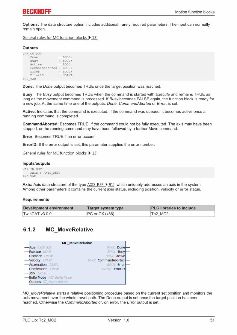
Motion function blocks
PLC Lib: Tc2_MC2 51Version: 1.6
Options: The data structure option includes additional, rarely required parameters. The input can normallyremain open.
General rules for MC function blocks [} 13]
OutputsVAR_OUTPUT Done : BOOL; Busy : BOOL; Active : BOOL; CommandAborted : BOOL; Error : BOOL; ErrorID : UDINT;END_VAR
Done: The Done output becomes TRUE once the target position was reached.
Busy: The Busy output becomes TRUE when the command is started with Execute and remains TRUE aslong as the movement command is processed. If Busy becomes FALSE again, the function block is ready fora new job. At the same time one of the outputs, Done, CommandAborted or Error, is set.
Active: Indicates that the command is executed. If the command was queued, it becomes active once arunning command is completed.
CommandAborted: Becomes TRUE, if the command could not be fully executed. The axis may have beenstopped, or the running command may have been followed by a further Move command.
Error: Becomes TRUE if an error occurs.
ErrorID: If the error output is set, this parameter supplies the error number.
General rules for MC function blocks [} 13]
Inputs/outputsVAR_IN_OUT Axis : AXIS_REF;END_VAR
Axis: Axis data structure of the type AXIS_REF [} 91], which uniquely addresses an axis in the system.Among other parameters it contains the current axis status, including position, velocity or error status.
Requirements
Development environment Target system type PLC libraries to includeTwinCAT v3.0.0 PC or CX (x86) Tc2_MC2
6.1.2 MC_MoveRelative
MC_MoveRelative starts a relative positioning procedure based on the current set position and monitors theaxis movement over the whole travel path. The Done output is set once the target position has beenreached. Otherwise the CommandAborted or, on error, the Error output is set.
Motion function blocks
PLC Lib: Tc2_MC252 Version: 1.6
Motion commands can be applied to coupled slave axes, if this option was explicitly activated in the axisparameters. A motion command such as MC_MoveAbsolute then automatically leads to uncoupling of theaxis, after which the command is executed. In this case only Buffer-ModeAborting is possible.
InputsVAR_INPUT Execute : BOOL; Distance : LREAL; Velocity : LREAL; Acceleration : LREAL; Deceleration : LREAL; Jerk : LREAL; BufferMode : MC_BufferMode; Options : ST_MoveOptions;END_VAR
Execute: The command is executed with a rising edge at input Execute.
Distance: Relative distance to be used for positioning.
Velocity: Maximum travel velocity (>0).
Acceleration: Acceleration (≥0). If the value is 0, the standard acceleration from the axis configuration in theSystem Manager is used.
Deceleration: Deceleration (≥0). If the value is 0, the standard deceleration from the axis configuration in theSystem Manager is used.
Jerk: Jerk (≥0). If the value is 0, the standard jerk from the axis configuration in the System Manager is used.
BufferMode: The BufferMode [} 102] is analyzed, if the axis is already executing another command. Therunning command can be aborted, or the new command becomes active after the running command. TheBufferMode also determines the transition condition from the current to the next command.If the command is applied to a coupled slave axis used, the only available buffer mode is Aborting.A second function block is required to use the buffer mode. It is not possible to trigger a move block with newparameters while it is active.
Options: The data structure option includes additional, rarely required parameters. The input can normallyremain open.
General rules for MC function blocks [} 13]
OutputsVAR_OUTPUT Done : BOOL; Busy : BOOL; Active : BOOL; CommandAborted : BOOL; Error : BOOL; ErrorID : UDINT;END_VAR
Done: The Done output becomes TRUE once the target position was reached.
Busy: The Busy output becomes TRUE when the command is started with Execute and remains TRUE aslong as the movement command is processed. If Busy becomes FALSE again, the function block is ready fora new job. At the same time one of the outputs, Done, CommandAborted or Error, is set.
Active: Indicates that the command is executed. If the command was queued, it becomes active once arunning command is completed.
CommandAborted: Becomes TRUE, if the command could not be fully executed. The axis may have beenstopped, or the running command may have been followed by a further Move command.
Error: Becomes TRUE if an error occurs.
ErrorID: If the error output is set, this parameter supplies the error number.
General rules for MC function blocks [} 13]
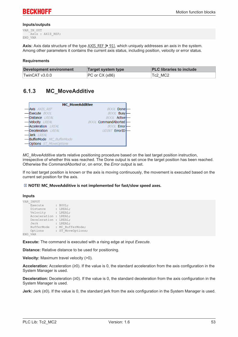
Motion function blocks
PLC Lib: Tc2_MC2 53Version: 1.6
Inputs/outputsVAR_IN_OUT Axis : AXIS_REF;END_VAR
Axis: Axis data structure of the type AXIS_REF [} 91], which uniquely addresses an axis in the system.Among other parameters it contains the current axis status, including position, velocity or error status.
Requirements
Development environment Target system type PLC libraries to includeTwinCAT v3.0.0 PC or CX (x86) Tc2_MC2
6.1.3 MC_MoveAdditive
MC_MoveAdditive starts relative positioning procedure based on the last target position instruction,irrespective of whether this was reached. The Done output is set once the target position has been reached.Otherwise the CommandAborted or, on error, the Error output is set.
If no last target position is known or the axis is moving continuously, the movement is executed based on thecurrent set position for the axis.
NOTE! MC_MoveAdditive is not implemented for fast/slow speed axes.
InputsVAR_INPUT Execute : BOOL; Distance : LREAL; Velocity : LREAL; Acceleration : LREAL; Deceleration : LREAL; Jerk : LREAL; BufferMode : MC_BufferMode; Options : ST_MoveOptions;END_VAR
Execute: The command is executed with a rising edge at input Execute.
Distance: Relative distance to be used for positioning.
Velocity: Maximum travel velocity (>0).
Acceleration: Acceleration (≥0). If the value is 0, the standard acceleration from the axis configuration in theSystem Manager is used.
Deceleration: Deceleration (≥0). If the value is 0, the standard deceleration from the axis configuration in theSystem Manager is used.
Jerk: Jerk (≥0). If the value is 0, the standard jerk from the axis configuration in the System Manager is used.
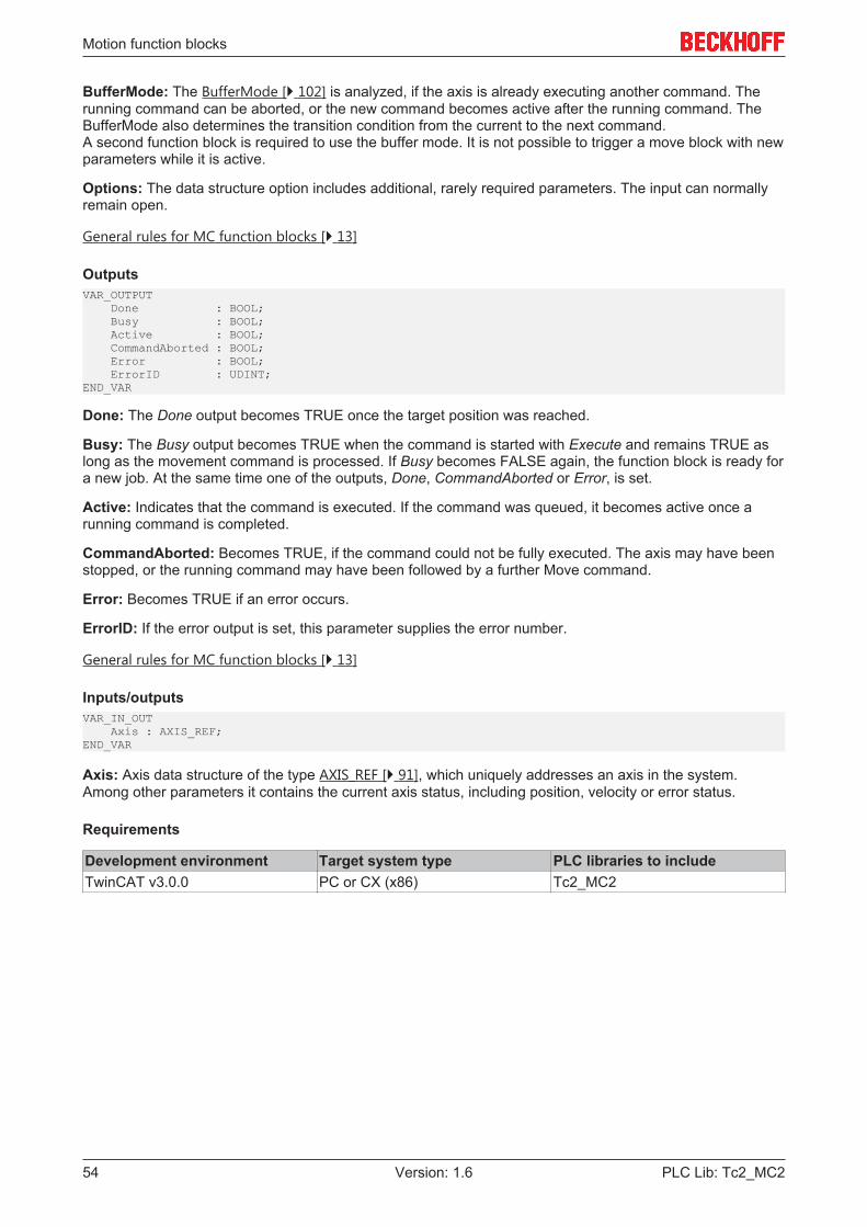
Motion function blocks
PLC Lib: Tc2_MC254 Version: 1.6
BufferMode: The BufferMode [} 102] is analyzed, if the axis is already executing another command. Therunning command can be aborted, or the new command becomes active after the running command. TheBufferMode also determines the transition condition from the current to the next command.A second function block is required to use the buffer mode. It is not possible to trigger a move block with newparameters while it is active.
Options: The data structure option includes additional, rarely required parameters. The input can normallyremain open.
General rules for MC function blocks [} 13]
OutputsVAR_OUTPUT Done : BOOL; Busy : BOOL; Active : BOOL; CommandAborted : BOOL; Error : BOOL; ErrorID : UDINT;END_VAR
Done: The Done output becomes TRUE once the target position was reached.
Busy: The Busy output becomes TRUE when the command is started with Execute and remains TRUE aslong as the movement command is processed. If Busy becomes FALSE again, the function block is ready fora new job. At the same time one of the outputs, Done, CommandAborted or Error, is set.
Active: Indicates that the command is executed. If the command was queued, it becomes active once arunning command is completed.
CommandAborted: Becomes TRUE, if the command could not be fully executed. The axis may have beenstopped, or the running command may have been followed by a further Move command.
Error: Becomes TRUE if an error occurs.
ErrorID: If the error output is set, this parameter supplies the error number.
General rules for MC function blocks [} 13]
Inputs/outputsVAR_IN_OUT Axis : AXIS_REF;END_VAR
Axis: Axis data structure of the type AXIS_REF [} 91], which uniquely addresses an axis in the system.Among other parameters it contains the current axis status, including position, velocity or error status.
Requirements
Development environment Target system type PLC libraries to includeTwinCAT v3.0.0 PC or CX (x86) Tc2_MC2
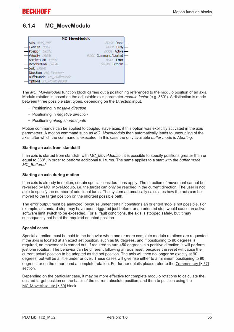
Motion function blocks
PLC Lib: Tc2_MC2 55Version: 1.6
6.1.4 MC_MoveModulo
The MC_MoveModulo function block carries out a positioning referenced to the modulo position of an axis.Modulo rotation is based on the adjustable axis parameter modulo factor (e.g. 360°). A distinction is madebetween three possible start types, depending on the Direction input.
• Positioning in positive direction• Positioning in negative direction• Positioning along shortest path
Motion commands can be applied to coupled slave axes, if this option was explicitly activated in the axisparameters. A motion command such as MC_MoveModulo then automatically leads to uncoupling of theaxis, after which the command is executed. In this case the only available buffer mode is Aborting.
Starting an axis from standstill
If an axis is started from standstill with MC_MoveModulo , it is possible to specify positions greater than orequal to 360°, in order to perform additional full turns. The same applies to a start with the buffer modeMC_Buffered .
Starting an axis during motion
If an axis is already in motion, certain special considerations apply. The direction of movement cannot bereversed by MC_MoveModulo, i.e. the target can only be reached in the current direction. The user is notable to specify the number of additional turns. The system automatically calculates how the axis can bemoved to the target position on the shortest possible path.
The error output must be analyzed, because under certain conditions an oriented stop is not possible. Forexample, a standard stop may have been triggered just before, or an oriented stop would cause an activesoftware limit switch to be exceeded. For all fault conditions, the axis is stopped safely, but it maysubsequently not be at the required oriented position.
Special cases
Special attention must be paid to the behavior when one or more complete modulo rotations are requested.If the axis is located at an exact set position, such as 90 degrees, and if positioning to 90 degrees isrequired, no movement is carried out. If required to turn 450 degrees in a positive direction, it will performjust one rotation. The behavior can be different following an axis reset, because the reset will cause thecurrent actual position to be adopted as the set position. The axis will then no longer be exactly at 90degrees, but will be a little under or over. These cases will give rise either to a minimum positioning to 90degrees, or on the other hand a complete rotation. For further details please refer to the Commentary [} 57]section.
Depending on the particular case, it may be more effective for complete modulo rotations to calculate thedesired target position on the basis of the current absolute position, and then to position using theMC_MoveAbsolute [} 50] block.
Motion function blocks
PLC Lib: Tc2_MC256 Version: 1.6
Note
Modulo positioning and absolute positioning are available for all axes, irrespective of theModulo setting in the TwinCAT System Manager. For each axis, the current absolute posi-tion SetPos can be read from the cyclic axis interface data type NCTOPLC_AXIS_REF [} 92].
See also: Further information on modulo movements [} 57]
InputsVAR_INPUT Execute : BOOL; Position : LREAL; Velocity : LREAL; Acceleration : LREAL; Deceleration : LREAL; Jerk : LREAL; Direction : MC_Direction; BufferMode : MC_BufferMode; Options : ST_MoveOptions;END_VAR
Execute: The command is executed with a rising edge at Execute input.
Position: Modulo target position to be used for positioning.If the axis is started from standstill, positions greater than 360° result in additional turns. Negative positionsare not permitted.
Velocity: Maximum travel velocity (>0).
Acceleration: Acceleration (≥0). If the value is 0, the standard acceleration from the axis configuration in theSystem Manager is used.
Deceleration: Deceleration (≥0). If the value is 0, the standard deceleration from the axis configuration in theSystem Manager is used.
Jerk: Jerk (≥0). If the value is 0, the standard jerk from the axis configuration in the System Manager is used.
Direction: Positive or negative direction of travel of type MC_Direction [} 104].If the axis is started during a motion, the direction may not be reversed.
BufferMode: The BufferMode [} 102] is analyzed, if the axis is already executing another command. Therunning command can be aborted, or the new command becomes active after the running command. TheBufferMode also determines the transition condition from the current to the next command.A second function block is required to use the buffer mode. It is not possible to trigger a move block with newparameters while it is active.
Options: The data structure option includes additional, rarely required parameters. The input can normallyremain open.
General rules for MC function blocks [} 13]
OutputsVAR_OUTPUT Done : BOOL; Busy : BOOL; Active : BOOL; CommandAborted : BOOL; Error : BOOL; ErrorID : UDINT;END_VAR
Done: The Done output becomes TRUE once the target position was reached.
Busy: The Busy output becomes TRUE when the command is started with Execute and remains TRUE aslong as the movement command is processed. If Busy becomes FALSE again, the function block is ready fora new job. At the same time one of the outputs, Done, CommandAborted or Error, is set.
Active: Indicates that the command is executed. If the command was queued, it becomes active once arunning command is completed.
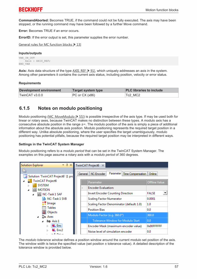
Motion function blocks
PLC Lib: Tc2_MC2 57Version: 1.6
CommandAborted: Becomes TRUE, if the command could not be fully executed. The axis may have beenstopped, or the running command may have been followed by a further Move command.
Error: Becomes TRUE if an error occurs.
ErrorID: If the error output is set, this parameter supplies the error number.
General rules for MC function blocks [} 13]
Inputs/outputsVAR_IN_OUT Axis : AXIS_REF;END_VAR
Axis: Axis data structure of the type AXIS_REF [} 91], which uniquely addresses an axis in the system.Among other parameters it contains the current axis status, including position, velocity or error status.
Requirements
Development environment Target system type PLC libraries to includeTwinCAT v3.0.0 PC or CX (x86) Tc2_MC2
6.1.5 Notes on modulo positioningModulo positioning (MC_MoveModulo [} 55]) is possible irrespective of the axis type. If may be used both forlinear or rotary axes, because TwinCAT makes no distinction between these types. A modulo axis has aconsecutive absolute position in the range ±∞. The modulo position of the axis is simply a piece of additionalinformation about the absolute axis position. Modulo positioning represents the required target position in adifferent way. Unlike absolute positioning, where the user specifies the target unambiguously, modulopositioning has potential pitfalls, because the required target position may be interpreted in different ways.
Settings in the TwinCAT System Manager
Modulo positioning refers to a modulo period that can be set in the TwinCAT System Manager. Theexamples on this page assume a rotary axis with a modulo period of 360 degrees.
The modulo tolerance window defines a position window around the current modulo set position of the axis.The window width is twice the specified value (set position ± tolerance value). A detailed description of thetolerance window is provided below.
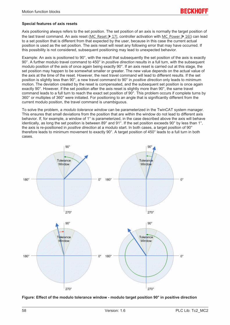
Motion function blocks
PLC Lib: Tc2_MC258 Version: 1.6
Special features of axis resets
Axis positioning always refers to the set position. The set position of an axis is normally the target position ofthe last travel command. An axis reset (MC_Reset [} 17], controller activation with MC_Power [} 16]) can leadto a set position that is different from that expected by the user, because in this case the current actualposition is used as the set position. The axis reset will reset any following error that may have occurred. Ifthis possibility is not considered, subsequent positioning may lead to unexpected behavior.
Example: An axis is positioned to 90°, with the result that subsequently the set position of the axis is exactly90°. A further modulo travel command to 450° in positive direction results in a full turn, with the subsequentmodulo position of the axis of once again being exactly 90°. If an axis reset is carried out at this stage, theset position may happen to be somewhat smaller or greater. The new value depends on the actual value ofthe axis at the time of the reset. However, the next travel command will lead to different results. If the setposition is slightly less than 90°, a new travel command to 90° in positive direction only leads to minimummotion. The deviation created by the reset is compensated, and the subsequent set position is once againexactly 90°. However, if the set position after the axis reset is slightly more than 90°, the same travelcommand leads to a full turn to reach the exact set position of 90°. This problem occurs if complete turns by360° or multiples of 360° were initiated. For positioning to an angle that is significantly different from thecurrent modulo position, the travel command is unambiguous.
To solve the problem, a modulo tolerance window can be parameterized in the TwinCAT system manager.This ensures that small deviations from the position that are within the window do not lead to different axisbehavior. If, for example, a window of 1° is parameterized, in the case described above the axis will behaveidentically, as long the set position is between 89° and 91°. If the set position exceeds 90° by less than 1°,the axis is re-positioned in positive direction at a modulo start. In both cases, a target position of 90°therefore leads to minimum movement to exactly 90°. A target position of 450° leads to a full turn in bothcases.
Figure: Effect of the modulo tolerance window - modulo target position 90° in positive direction

Motion function blocks
PLC Lib: Tc2_MC2 59Version: 1.6
For values that are within the window range, the modulo tolerance window can therefore lead to movementsagainst the specified direction. For small windows this is usually not a problem, because system deviationsbetween set and actual position are compensated in both directions. This means that the tolerance windowmay also be used for axes that may only be moved in one direction due to their construction.
Modulo positioning by less than one turn
Modulo positioning from a starting position to a non-identical target position is unambiguous and requires nospecial consideration. A modulo target position in the range [0 ≤; position < 360] reaches the required targetin less than one whole turn. No motion occurs if target position and starting position are identical. Targetpositions of more than 360 degrees lead to one or more full turns before the axis travels to the requiredtarget position.
For a movement from 270° to 0°, a modulo target position of 0° (not 360°) should therefore be specified,because 360 is outside the basic range and would lead to an additional turn.
For modulo positioning, a distinction is made between three different directions, i.e. positive direction,negative direction and along shortest path (MC_Direction [} 104]). For positioning along the shortest path,target positions of more than 360° are not sensible, because the movement towards the target is alwaysdirect. In contrast to positive or negative direction, it is therefore not possible to carry out several turns beforethe axis moves to the target.
NOTE! For modulo positioning with start type along shortest path , only modulo target positionswithin the basic period (e.g. less than 360°) are permitted, otherwise an error is returned.
The following table shows some positioning examples:
Direction (modulo start type)
Absolute start posi-tion
Modulo target posi-tion
Relative travel path Absolute end position Modulo end position
positive direction 90.00 0.00 270.00 360.00 0.00positive direction 90.00 360.00 630.00 720.00 0.00positive direction 90.00 720.00 990.00 1080.00 0.00
negative direction 90.00 0.00 -90.00 0.00 0.00negative direction 90.00 360.00 -450.00 -360.00 0.00negative direction 90.00 720.00 -810.00 -720.00 0.00
along shortest path 90.00 0.00 -90.00 0.00 0.00
Modulo positioning with full turns
In principle, modulo positioning by one or full turns are no different than positioning to an angle that differsfrom the starting position. No motion occurs if target position and starting position are identical. For a fullturn, 360° has to be added to the starting position.
The reset behavior described above shows that positioning with full turns requires particular attention. Thefollowing table shows positioning examples for a starting position of approximately 90°. The modulotolerance window (TW) is set to 1°. Special cases for which the starting position is outside this window areidentified.

Motion function blocks
PLC Lib: Tc2_MC260 Version: 1.6
Direction (modulo starttype)
Absolute start po-sition
Modulo target po-sition
Relative travelpath
Absolute end po-sition
Modulo end posi-tion
Note
positive direction 90.00 90.00 0.00 90.00 90.00positive direction 90.90 90.00 -0.90 90.00 90.00positive direction 91.10 90.00 358.90 450.00 90.00 outside TFpositive direction 89.10 90.00 0.90 90.00 90.00positive direction 88.90 90.00 1.10 90.00 90.00 outside TF
positive direction 90.00 450.00 360.00 450.00 90.00positive direction 90.90 450.00 359.10 450.00 90.00positive direction 91.10 450.00 718.90 810.00 90.00 outside TFpositive direction 89.10 450.00 360.90 450.00 90.00positive direction 88.90 450.00 361.10 450.00 90.00 outside TF
positive direction 90.00 810.00 720.00 810.00 90.00positive direction 90.90 810.00 719.10 810.00 90.00positive direction 91.10 810.00 1078.90 1170.00 90.00 outside TFpositive direction 89.10 810.00 720.90 810.00 90.00positive direction 88.90 810.00 721.10 810.00 90.00 outside TF
negative direction 90.00 90.00 0.00 90.00 90.00negative direction 90.90 90.00 -0.90 90.00 90.00negative direction 91.10 90.00 -1.10 90.00 90.00 outside TFnegative direction 89.10 90.00 0.90 90.00 90.00negative direction 88.90 90.00 -358.90 -270.00 90.00 outside TF
negative direction 90.00 450.00 -360.00 -270.00 90.00negative direction 90.90 450.00 -360.90 -270.00 90.00negative direction 91.10 450.00 -361.10 -270.00 90.00 outside TFnegative direction 89.10 450.00 -359.10 -270.00 90.00negative direction 88.90 450.00 -718.90 -630.00 90.00 outside TF
negative direction 90.00 810.00 -720.00 -630.00 90.00negative direction 90.90 810.00 -720.90 -630.00 90.00negative direction 91.10 810.00 -721.10 -630.00 90.00 outside TFnegative direction 89.10 810.00 -719.10 -630.00 90.00negative direction 88.90 810.00 -1078.90 -990.00 90.00 outside TF
Modulo calculations within the PLC program
In TwinCAT NC, all axis positioning tasks are executed based on the set position. The current actual positionis only used for control purposes. If a PLC program is to calculate a new target position based on the currentposition, the current set position of the axis has to be used in the calculation (Axis.NcToPlc.ModuloSetPosand Axis.NcToPlc.ModuloSetTurns).
It is not recommended to perform order calculations on basis of the modulo actual position available in thecyclic axis interface (ModuloActPos and ModuloActTurns). Due to the larger or smaller control deviation ofthe axis, errors can occur in the programmed sequence, such as unwanted rotations.
Application example
Within a system, a rotational axis carries out an operation. The starting position for each operation is 90°,and with each cycle the axis is to be positioned by 360° in positive direction. Reverse positioning is notpermitted for mechanical reasons. Small reverse positioning is acceptable as part of position controlmovements.

Motion function blocks
PLC Lib: Tc2_MC2 61Version: 1.6
The modulo tolerance window is set to 1.5° in the System Manager. This ensures that undesirable axis turnsafter an axis reset are avoided. Since the axis may only be positioned in positive direction, the commandMC_MoveModulo [} 55] with modulo start type positive direction (MC_Positive_Direction) is used. Themodulo target position is specified as 450°, since the original orientation is to be reached again after a fullturn by 360°. A modulo target position of 90° would not lead to any motion.
The process starts with a basic positioning movement (MC_MoveModulo [} 55]) to ensure that the startingposition is accurate. The step sequence then changes into an execution cycle. In the event of a fault, theaxis is reset with MC_Reset [} 17] and subsequently (at the start of the step sequence) moved to its validstarting position. In this case, 90° is specified as the target position to enable this position to be reached asquickly as possible. No motion occurs if the axis is already at the starting position.
Alternatively, the reset step may be carried out at the start of the step sequence, so that the axis is initializedat the start of the process.
Requirements
Development environment Target system type PLC libraries to includeTwinCAT v3.0.0 PC or CX (x86) Tc2_MC2
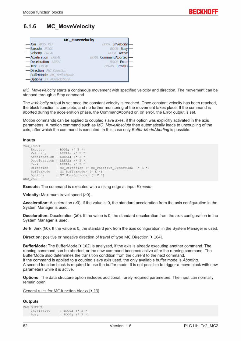
Motion function blocks
PLC Lib: Tc2_MC262 Version: 1.6
6.1.6 MC_MoveVelocity
MC_MoveVelocity starts a continuous movement with specified velocity and direction. The movement can bestopped through a Stop command.
The InVelocity output is set once the constant velocity is reached. Once constant velocity has been reached,the block function is complete, and no further monitoring of the movement takes place. If the command isaborted during the acceleration phase, the CommandAborted or, on error, the Error output is set.
Motion commands can be applied to coupled slave axes, if this option was explicitly activated in the axisparameters. A motion command such as MC_MoveAbsolute then automatically leads to uncoupling of theaxis, after which the command is executed. In this case only Buffer-ModeAborting is possible.
InputsVAR_INPUT Execute : BOOL; (* B *) Velocity : LREAL; (* E *) Acceleration : LREAL; (* E *) Deceleration : LREAL; (* E *) Jerk : LREAL; (* E *) Direction : MC_Direction := MC_Positive_Direction; (* E *) BufferMode : MC_BufferMode; (* E *) Options : ST_MoveOptions; (* V *)END_VAR
Execute: The command is executed with a rising edge at input Execute.
Velocity: Maximum travel speed (>0).
Acceleration: Acceleration (≥0). If the value is 0, the standard acceleration from the axis configuration in theSystem Manager is used.
Deceleration: Deceleration (≥0). If the value is 0, the standard deceleration from the axis configuration in theSystem Manager is used.
Jerk: Jerk (≥0). If the value is 0, the standard jerk from the axis configuration in the System Manager is used.
Direction: positive or negative direction of travel of type MC_Direction [} 104].
BufferMode: The BufferMode [} 102] is analyzed, if the axis is already executing another command. Therunning command can be aborted, or the new command becomes active after the running command. TheBufferMode also determines the transition condition from the current to the next command.If the command is applied to a coupled slave axis used, the only available buffer mode is Aborting.A second function block is required to use the buffer mode. It is not possible to trigger a move block with newparameters while it is active.
Options: The data structure option includes additional, rarely required parameters. The input can normallyremain open.
General rules for MC function blocks [} 13]
OutputsVAR_OUTPUT InVelocity : BOOL; (* B *) Busy : BOOL; (* E *)
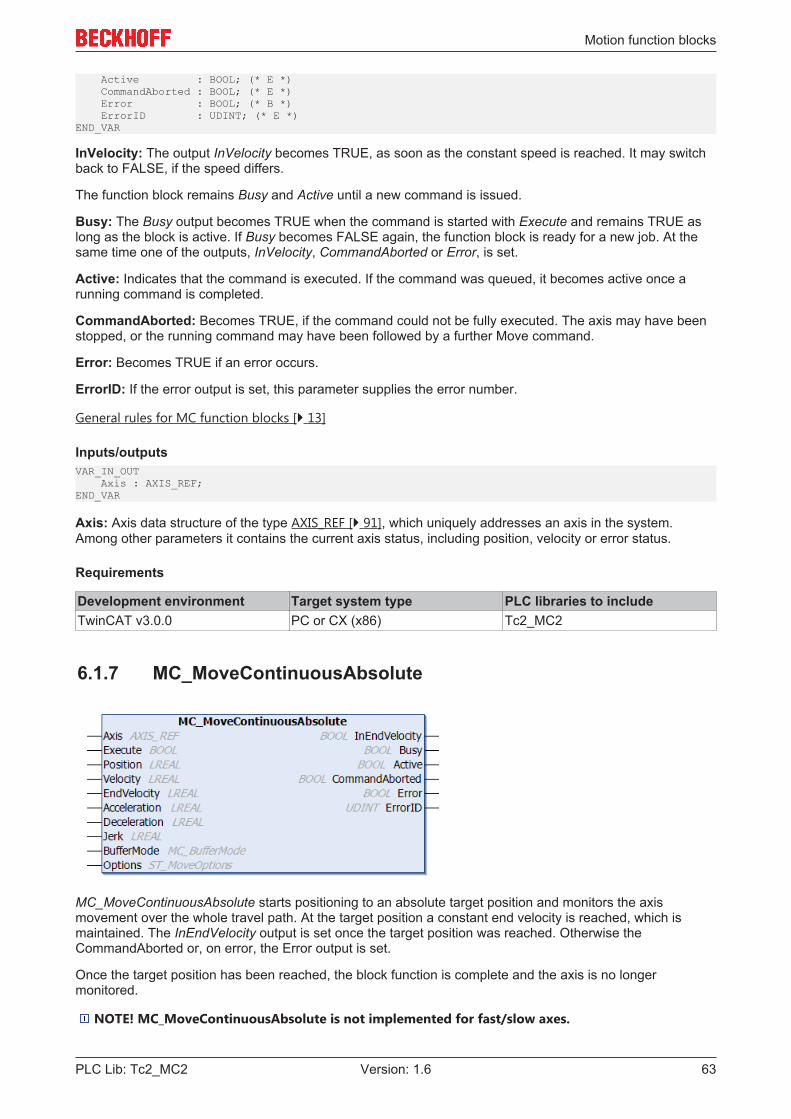
Motion function blocks
PLC Lib: Tc2_MC2 63Version: 1.6
Active : BOOL; (* E *) CommandAborted : BOOL; (* E *) Error : BOOL; (* B *) ErrorID : UDINT; (* E *)END_VAR
InVelocity: The output InVelocity becomes TRUE, as soon as the constant speed is reached. It may switchback to FALSE, if the speed differs.
The function block remains Busy and Active until a new command is issued.
Busy: The Busy output becomes TRUE when the command is started with Execute and remains TRUE aslong as the block is active. If Busy becomes FALSE again, the function block is ready for a new job. At thesame time one of the outputs, InVelocity, CommandAborted or Error, is set.
Active: Indicates that the command is executed. If the command was queued, it becomes active once arunning command is completed.
CommandAborted: Becomes TRUE, if the command could not be fully executed. The axis may have beenstopped, or the running command may have been followed by a further Move command.
Error: Becomes TRUE if an error occurs.
ErrorID: If the error output is set, this parameter supplies the error number.
General rules for MC function blocks [} 13]
Inputs/outputsVAR_IN_OUT Axis : AXIS_REF;END_VAR
Axis: Axis data structure of the type AXIS_REF [} 91], which uniquely addresses an axis in the system.Among other parameters it contains the current axis status, including position, velocity or error status.
Requirements
Development environment Target system type PLC libraries to includeTwinCAT v3.0.0 PC or CX (x86) Tc2_MC2
6.1.7 MC_MoveContinuousAbsolute
MC_MoveContinuousAbsolute starts positioning to an absolute target position and monitors the axismovement over the whole travel path. At the target position a constant end velocity is reached, which ismaintained. The InEndVelocity output is set once the target position was reached. Otherwise theCommandAborted or, on error, the Error output is set.
Once the target position has been reached, the block function is complete and the axis is no longermonitored.
NOTE! MC_MoveContinuousAbsolute is not implemented for fast/slow axes.
Motion function blocks
PLC Lib: Tc2_MC264 Version: 1.6
InputsVAR_INPUT Execute : BOOL; Position : LREAL; Velocity : LREAL; EndVelocity : LREAL; Acceleration : LREAL; Deceleration : LREAL; Jerk : LREAL; BufferMode : MC_BufferMode; Options : ST_MoveOptions;END_VAR
Execute: The command is executed with a rising edge at input Execute.
Position: Absolute target position
Velocity: Maximum velocity for the movement to the target position (>0).
EndVelocity: End velocity to be maintained once the target position has been reached.
Acceleration: Acceleration (≥0). If the value is 0, the standard acceleration from the axis configuration in theSystem Manager is used.
Deceleration: Deceleration (≥0). If the value is 0, the standard deceleration from the axis configuration in theSystem Manager is used.
Jerk: Jerk (≥0). If the value is 0, the standard jerk from the axis configuration in the System Manager is used.
BufferMode: The BufferMode [} 102] is analyzed, if the axis is already executing another command. Therunning command can be aborted, or the new command becomes active after the running command. TheBufferMode also determines the transition condition from the current to the next command.A second function block is required to use the buffer mode. It is not possible to trigger a move block with newparameters while it is active.
Options: The data structure option includes additional, rarely required parameters. The input can normallyremain open.
General rules for MC function blocks [} 13]
OutputsVAR_OUTPUT InEndVelocity : BOOL; Busy : BOOL; Active : BOOL; CommandAborted : BOOL; Error : BOOL; ErrorID : UDINT;END_VAR
InEndVelocity: The InEndVelocity output becomes TRUE once the target position was reached.
The function block remains Busy and Active until the command is released.
Busy: The Busy output becomes TRUE when the command is started with Execute and remains TRUE aslong as the movement command is processed. If Busy becomes FALSE again, the function block is ready fora new job. At the same time one of the outputs, Done, CommandAborted or Error, is set.
Active: Indicates that the command is executed. If the command was queued, it becomes active once arunning command is completed.
CommandAborted: Becomes TRUE, if the command could not be fully executed. The axis may have beenstopped, or the running command may have been followed by a further Move command.
Error: Becomes TRUE if an error occurs.
ErrorID: If the error output is set, this parameter supplies the error number.
General rules for MC function blocks [} 13]
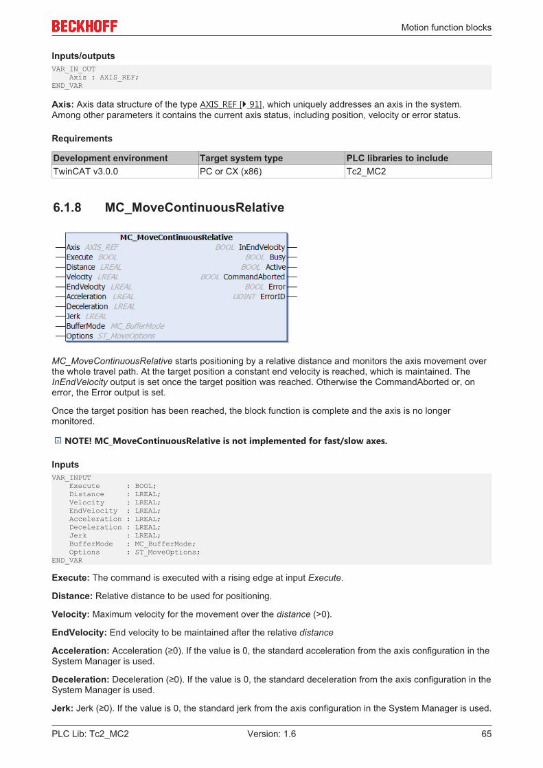
Motion function blocks
PLC Lib: Tc2_MC2 65Version: 1.6
Inputs/outputsVAR_IN_OUT Axis : AXIS_REF;END_VAR
Axis: Axis data structure of the type AXIS_REF [} 91], which uniquely addresses an axis in the system.Among other parameters it contains the current axis status, including position, velocity or error status.
Requirements
Development environment Target system type PLC libraries to includeTwinCAT v3.0.0 PC or CX (x86) Tc2_MC2
6.1.8 MC_MoveContinuousRelative
MC_MoveContinuousRelative starts positioning by a relative distance and monitors the axis movement overthe whole travel path. At the target position a constant end velocity is reached, which is maintained. TheInEndVelocity output is set once the target position was reached. Otherwise the CommandAborted or, onerror, the Error output is set.
Once the target position has been reached, the block function is complete and the axis is no longermonitored.
NOTE! MC_MoveContinuousRelative is not implemented for fast/slow axes.
InputsVAR_INPUT Execute : BOOL; Distance : LREAL; Velocity : LREAL; EndVelocity : LREAL; Acceleration : LREAL; Deceleration : LREAL; Jerk : LREAL; BufferMode : MC_BufferMode; Options : ST_MoveOptions;END_VAR
Execute: The command is executed with a rising edge at input Execute.
Distance: Relative distance to be used for positioning.
Velocity: Maximum velocity for the movement over the distance (>0).
EndVelocity: End velocity to be maintained after the relative distance
Acceleration: Acceleration (≥0). If the value is 0, the standard acceleration from the axis configuration in theSystem Manager is used.
Deceleration: Deceleration (≥0). If the value is 0, the standard deceleration from the axis configuration in theSystem Manager is used.
Jerk: Jerk (≥0). If the value is 0, the standard jerk from the axis configuration in the System Manager is used.
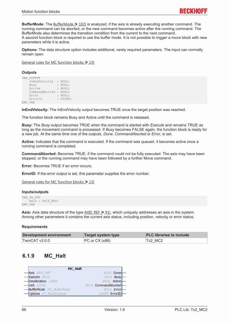
Motion function blocks
PLC Lib: Tc2_MC266 Version: 1.6
BufferMode: The BufferMode [} 102] is analyzed, if the axis is already executing another command. Therunning command can be aborted, or the new command becomes active after the running command. TheBufferMode also determines the transition condition from the current to the next command.A second function block is required to use the buffer mode. It is not possible to trigger a move block with newparameters while it is active.
Options: The data structure option includes additional, rarely required parameters. The input can normallyremain open.
General rules for MC function blocks [} 13]
OutputsVAR_OUTPUT InEndVelocity : BOOL; Busy : BOOL; Active : BOOL; CommandAborted : BOOL; Error : BOOL; ErrorID : UDINT;END_VAR
InEndVelocity: The InEndVelocity output becomes TRUE once the target position was reached.
The function block remains Busy and Active until the command is released.
Busy: The Busy output becomes TRUE when the command is started with Execute and remains TRUE aslong as the movement command is processed. If Busy becomes FALSE again, the function block is ready fora new job. At the same time one of the outputs, Done, CommandAborted or Error, is set.
Active: Indicates that the command is executed. If the command was queued, it becomes active once arunning command is completed.
CommandAborted: Becomes TRUE, if the command could not be fully executed. The axis may have beenstopped, or the running command may have been followed by a further Move command.
Error: Becomes TRUE if an error occurs.
ErrorID: If the error output is set, this parameter supplies the error number.
General rules for MC function blocks [} 13]
Inputs/outputsVAR_IN_OUT Axis : AXIS_REF;END_VAR
Axis: Axis data structure of the type AXIS_REF [} 91], which uniquely addresses an axis in the system.Among other parameters it contains the current axis status, including position, velocity or error status.
Requirements
Development environment Target system type PLC libraries to includeTwinCAT v3.0.0 PC or CX (x86) Tc2_MC2
6.1.9 MC_Halt

Motion function blocks
PLC Lib: Tc2_MC2 67Version: 1.6
MC_Halt stops an axis with a defined braking ramp.
In contrast to MC_Stop [} 68], the axis is not locked against further movement commands. The axis cantherefore be restarted through a further command during the braking ramp or after it has come to a halt.
Travel commands can be applied to coupled slave axes, if this option was explicitly activated in the axisparameters. A motion command such as MC_Halt then automatically leads to uncoupling of the axis, afterwhich the command is executed. In this case only Buffer-ModeAborting is possible.
InputsVAR_INPUT Execute : BOOL; Deceleration : LREAL; Jerk : LREAL; BufferMode : MC_BufferMode; Options : ST_MoveOptions; END_VAR
Execute: The command is executed with a rising edge at input Execute.
Deceleration: Deceleration. If the value is ≤ 0, the deceleration parameterized with the last Move commandis used.For safety reasons MC_Halt and MC_Stop [} 68] cannot be executed with weaker dynamics than thecurrently active travel command. The parameterization is adjusted automatically, if necessary.
Jerk: Jerk. If the value is ≤ 0, the jerk parameterized with the last Move command is used.For safety reasons MC_Halt and MC_Stop [} 68] cannot be executed with weaker dynamics than thecurrently active travel command. The parameterization is adjusted automatically, if necessary.
BufferMode: The BufferMode [} 102] is analyzed, if the axis is already executing another command. Therunning command can be aborted, or the new command becomes active after the running command. TheBufferMode also determines the transition condition from the current to the next command.If the command is applied to a coupled slave axis used, the only available buffer mode is Aborting.Special characteristics of MC_Halt: The MC_buffer mode has no effect, if the command is executed whenthe system is at a standstill. The blending modes MC_BlendingNext and MC_BlendingLow do not changethe last target position, although they can result in a change in dynamics (deceleration) of the stop ramp. Themodes MC_BlendingPrevious and MC_BlendingHigh extend the travel to the original target position. Thestop ramp is only initiated when this position is reached (defined braking point).
Options: Currently not implemented - The data structure option includes additional, rarely requiredparameters. The input can normally remain open.
General rules for MC function blocks [} 13]
OutputsVAR_OUTPUT Done : BOOL; Busy : BOOL; Active : BOOL; CommandAborted : BOOL; Error : BOOL; ErrorID : UDINT;END_VAR
Done: The Done output becomes TRUE, if the axis was stopped and has come to a standstill.
Busy: The Busy output becomes TRUE when the command is started with Execute and remains TRUE aslong as the command is processed. If Busy becomes FALSE again, the function block is ready for a new job.At the same time one of the outputs, Done, CommandAborted or Error, is set.
Active: Indicates that the command is executed. If the command was queued, it becomes active once arunning command is completed.
CommandAborted: Becomes TRUE, if the command could not be fully executed. The running commandmay have been followed by a Move command.
Error: Becomes TRUE if an error occurs.
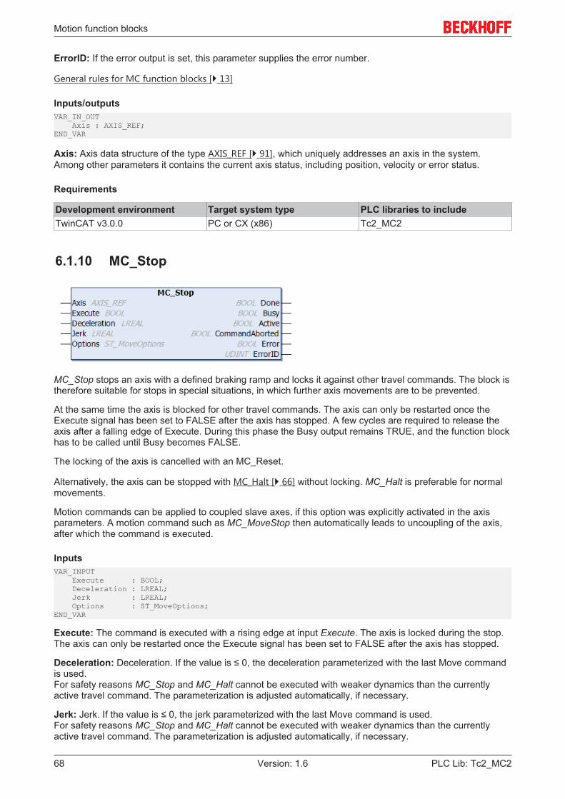
Motion function blocks
PLC Lib: Tc2_MC268 Version: 1.6
ErrorID: If the error output is set, this parameter supplies the error number.
General rules for MC function blocks [} 13]
Inputs/outputsVAR_IN_OUT Axis : AXIS_REF;END_VAR
Axis: Axis data structure of the type AXIS_REF [} 91], which uniquely addresses an axis in the system.Among other parameters it contains the current axis status, including position, velocity or error status.
Requirements
Development environment Target system type PLC libraries to includeTwinCAT v3.0.0 PC or CX (x86) Tc2_MC2
6.1.10 MC_Stop
MC_Stop stops an axis with a defined braking ramp and locks it against other travel commands. The block istherefore suitable for stops in special situations, in which further axis movements are to be prevented.
At the same time the axis is blocked for other travel commands. The axis can only be restarted once theExecute signal has been set to FALSE after the axis has stopped. A few cycles are required to release theaxis after a falling edge of Execute. During this phase the Busy output remains TRUE, and the function blockhas to be called until Busy becomes FALSE.
The locking of the axis is cancelled with an MC_Reset.
Alternatively, the axis can be stopped with MC_Halt [} 66] without locking. MC_Halt is preferable for normalmovements.
Motion commands can be applied to coupled slave axes, if this option was explicitly activated in the axisparameters. A motion command such as MC_MoveStop then automatically leads to uncoupling of the axis,after which the command is executed.
InputsVAR_INPUT Execute : BOOL; Deceleration : LREAL; Jerk : LREAL; Options : ST_MoveOptions; END_VAR
Execute: The command is executed with a rising edge at input Execute. The axis is locked during the stop.The axis can only be restarted once the Execute signal has been set to FALSE after the axis has stopped.
Deceleration: Deceleration. If the value is ≤ 0, the deceleration parameterized with the last Move commandis used.For safety reasons MC_Stop and MC_Halt cannot be executed with weaker dynamics than the currentlyactive travel command. The parameterization is adjusted automatically, if necessary.
Jerk: Jerk. If the value is ≤ 0, the jerk parameterized with the last Move command is used.For safety reasons MC_Stop and MC_Halt cannot be executed with weaker dynamics than the currentlyactive travel command. The parameterization is adjusted automatically, if necessary.
Motion function blocks
PLC Lib: Tc2_MC2 69Version: 1.6
Options: Currently not implemented - The data structure option includes additional, rarely requiredparameters. The input can normally remain open.
General rules for MC function blocks [} 13]
OutputsVAR_OUTPUT Done : BOOL; Busy : BOOL; Active : BOOL; CommandAborted : BOOL; Error : BOOL; ErrorID : UDINT;END_VAR
Done: The Done output becomes TRUE, if the axis was stopped and has come to a standstill.
Busy: The Busy output becomes TRUE when the command is started with Execute and remains TRUE aslong as the command is processed. If Busy becomes FALSE again, the function block is ready for a new job.Busy remains TRUE as long as the axis is locked. The axis is only unlocked and Busy becomes FALSEwhen Execute is set to FALSE.
Active: Indicates that the function block controls the axis.Active remains TRUE as long as the axis is locked. The axis is only unlocked and Active becomes FALSEwhen Execute is set to FALSE.
CommandAborted: Becomes TRUE, if the command could not be fully executed.
Error: Becomes TRUE if an error occurs.
ErrorID: If the error output is set, this parameter supplies the error number.
General rules for MC function blocks [} 13]
Inputs/outputsVAR_IN_OUT Axis : AXIS_REF;END_VAR
Axis: Axis data structure of the type AXIS_REF [} 91], which uniquely addresses an axis in the system.Among other parameters it contains the current axis status, including position, velocity or error status.
Requirements
Development environment Target system type PLC libraries to includeTwinCAT v3.0.0 PC or CX (x86) Tc2_MC2
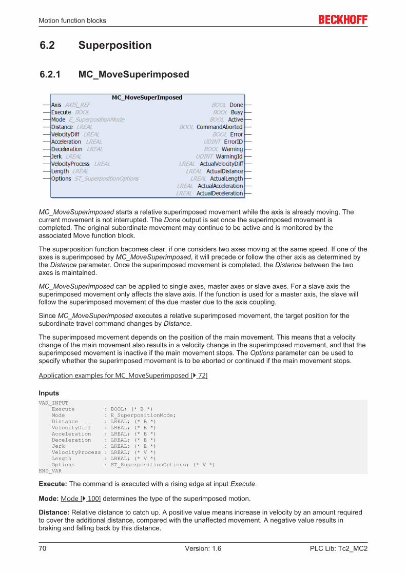
Motion function blocks
PLC Lib: Tc2_MC270 Version: 1.6
6.2 Superposition
6.2.1 MC_MoveSuperimposed
MC_MoveSuperimposed starts a relative superimposed movement while the axis is already moving. Thecurrent movement is not interrupted. The Done output is set once the superimposed movement iscompleted. The original subordinate movement may continue to be active and is monitored by theassociated Move function block.
The superposition function becomes clear, if one considers two axes moving at the same speed. If one of theaxes is superimposed by MC_MoveSuperimposed, it will precede or follow the other axis as determined bythe Distance parameter. Once the superimposed movement is completed, the Distance between the twoaxes is maintained.
MC_MoveSuperimposed can be applied to single axes, master axes or slave axes. For a slave axis thesuperimposed movement only affects the slave axis. If the function is used for a master axis, the slave willfollow the superimposed movement of the due master due to the axis coupling.
Since MC_MoveSuperimposed executes a relative superimposed movement, the target position for thesubordinate travel command changes by Distance.
The superimposed movement depends on the position of the main movement. This means that a velocitychange of the main movement also results in a velocity change in the superimposed movement, and that thesuperimposed movement is inactive if the main movement stops. The Options parameter can be used tospecify whether the superimposed movement is to be aborted or continued if the main movement stops.
Application examples for MC_MoveSuperimposed [} 72]
InputsVAR_INPUT Execute : BOOL; (* B *) Mode : E_SuperpositionMode; Distance : LREAL; (* B *) VelocityDiff : LREAL; (* E *) Acceleration : LREAL; (* E *) Deceleration : LREAL; (* E *) Jerk : LREAL; (* E *) VelocityProcess : LREAL; (* V *) Length : LREAL; (* V *) Options : ST_SuperpositionOptions; (* V *)END_VAR
Execute: The command is executed with a rising edge at input Execute.
Mode: Mode [} 100] determines the type of the superimposed motion.
Distance: Relative distance to catch up. A positive value means increase in velocity by an amount requiredto cover the additional distance, compared with the unaffected movement. A negative value results inbraking and falling back by this distance.
Motion function blocks
PLC Lib: Tc2_MC2 71Version: 1.6
VelocityDiff: Maximum velocity difference to the current velocity (basic velocity) of the axis (>0).For this parameter a distinction may have to be made, depending on the superimposition direction(acceleration or deceleration). If , for example, a direction reversal is not permitted, the maximum availableacceleration corresponds to the maximum velocity, and the maximum deceleration to stop. Therefore, thereare two possible maximum values for VelocityDiff:
• 1. Distance > 0 (axis accelerates)VelocityDiff = maximum velocity – basic velocity
• 2. Distance < 0 (axis decelerates)VelocityDiff = basic velocity
Acceleration: Acceleration (≥0). If the value is 0, the standard acceleration from the axis configuration in theSystem Manager is used.
Deceleration: Deceleration (≥0). If the value is 0, the standard deceleration from the axis configuration in theSystem Manager is used.
Jerk: Jerk (≥0). If the value is 0, the standard jerk from the axis configuration in the System Manager is used.
VelocityProcess: Mean process speed in the axis (>0).If the basic velocity during superposition is constant,the set axis velocity can be specified.
Length: Distance over which the superimposed movement is available. The Mode parameter defines howthis distance is interpreted.
Options: The data structure option [} 106] includes additional, rarely required parameters. The input cannormally remain open.
• AbortOption: AbortOption defines the behavior when the subordinate movement stops. Thesuperimposed movement can be aborted or continued later.
General rules for MC function blocks [} 13]
OutputsVAR_OUTPUT Done : BOOL; Busy : BOOL; Active : BOOL; CommandAborted : BOOL; Error : BOOL; ErrorID : UDINT; Warning : BOOL; WarningID : UDINT; ActualVelocityDiff : LREAL; ActualDistance : LREAL; ActualLength : LREAL; ActualAcceleration : LREAL; ActualDeceleration : LREAL;END_VAR
Done: The Done output becomes TRUE, once the superimposed movement was completed successfully.
Busy: The Busy output becomes TRUE when the command is started with Execute and remains TRUE aslong as the movement command is processed. If Busy becomes FALSE again, the function block is ready fora new job. At the same time one of the outputs, Done, CommandAborted or Error, is set.
Active: Indicates that the command is executed.
CommandAborted: Becomes TRUE, if the command was aborted by another command and could thereforenot be completed.
Error: Becomes TRUE if an error occurs.
ErrorID: If the error output is set, this parameter supplies the error number
Warning: Warning becomes TRUE if the action cannot be executed completely.
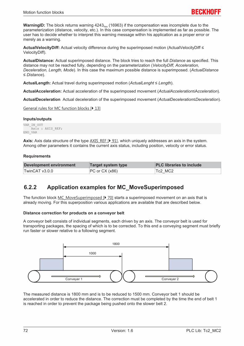
Motion function blocks
PLC Lib: Tc2_MC272 Version: 1.6
WarningID: The block returns warning 4243hex (16963) if the compensation was incomplete due to theparameterization (distance, velocity, etc.). In this case compensation is implemented as far as possible. Theuser has to decide whether to interpret this warning message within his application as a proper error ormerely as a warning.
ActualVelocityDiff: Actual velocity difference during the superimposed motion (ActualVelocityDiff ≤VelocityDiff).
ActualDistance: Actual superimposed distance. The block tries to reach the full Distance as specified. Thisdistance may not be reached fully, depending on the parameterization (VelocityDiff, Acceleration,Deceleration, Length, Mode). In this case the maximum possible distance is superimposed. (ActualDistance≤ Distance).
ActualLength: Actual travel during superimposed motion (ActualLenght ≤ Length).
ActualAcceleration: Actual acceleration of the superimposed movement (ActualAcceleration≤Acceleration).
ActualDeceleration Actual deceleration of the superimposed movement (ActualDeceleration≤Deceleration).
General rules for MC function blocks [} 13]
Inputs/outputsVAR_IN_OUT Axis : AXIS_REF;END_VAR
Axis: Axis data structure of the type AXIS_REF [} 91], which uniquely addresses an axis in the system.Among other parameters it contains the current axis status, including position, velocity or error status.
Requirements
Development environment Target system type PLC libraries to includeTwinCAT v3.0.0 PC or CX (x86) Tc2_MC2
6.2.2 Application examples for MC_MoveSuperimposedThe function block MC_MoveSuperimposed [} 70] starts a superimposed movement on an axis that isalready moving. For this superposition various applications are available that are described below.
Distance correction for products on a conveyor belt
A conveyor belt consists of individual segments, each driven by an axis. The conveyor belt is used fortransporting packages, the spacing of which is to be corrected. To this end a conveying segment must brieflyrun faster or slower relative to a following segment.
The measured distance is 1800 mm and is to be reduced to 1500 mm. Conveyor belt 1 should beaccelerated in order to reduce the distance. The correction must be completed by the time the end of belt 1is reached in order to prevent the package being pushed onto the slower belt 2.
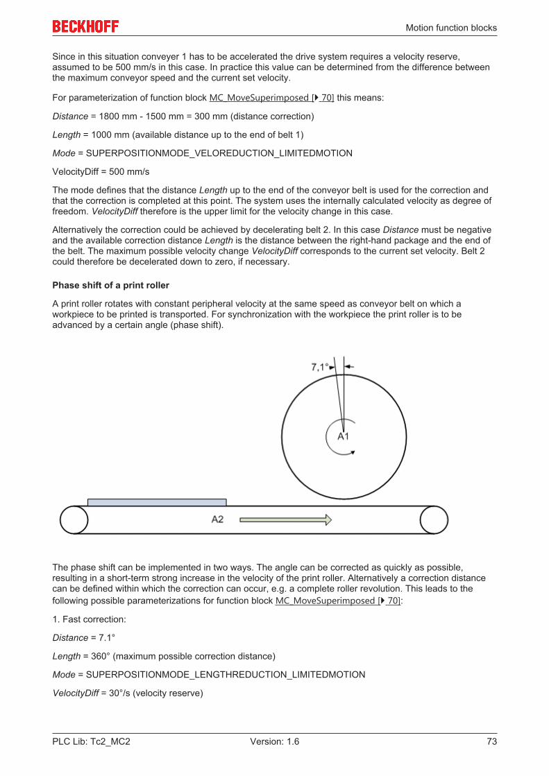
Motion function blocks
PLC Lib: Tc2_MC2 73Version: 1.6
Since in this situation conveyer 1 has to be accelerated the drive system requires a velocity reserve,assumed to be 500 mm/s in this case. In practice this value can be determined from the difference betweenthe maximum conveyor speed and the current set velocity.
For parameterization of function block MC_MoveSuperimposed [} 70] this means:
Distance = 1800 mm - 1500 mm = 300 mm (distance correction)
Length = 1000 mm (available distance up to the end of belt 1)
Mode = SUPERPOSITIONMODE_VELOREDUCTION_LIMITEDMOTION
VelocityDiff = 500 mm/s
The mode defines that the distance Length up to the end of the conveyor belt is used for the correction andthat the correction is completed at this point. The system uses the internally calculated velocity as degree offreedom. VelocityDiff therefore is the upper limit for the velocity change in this case.
Alternatively the correction could be achieved by decelerating belt 2. In this case Distance must be negativeand the available correction distance Length is the distance between the right-hand package and the end ofthe belt. The maximum possible velocity change VelocityDiff corresponds to the current set velocity. Belt 2could therefore be decelerated down to zero, if necessary.
Phase shift of a print roller
A print roller rotates with constant peripheral velocity at the same speed as conveyor belt on which aworkpiece to be printed is transported. For synchronization with the workpiece the print roller is to beadvanced by a certain angle (phase shift).
The phase shift can be implemented in two ways. The angle can be corrected as quickly as possible,resulting in a short-term strong increase in the velocity of the print roller. Alternatively a correction distancecan be defined within which the correction can occur, e.g. a complete roller revolution. This leads to thefollowing possible parameterizations for function block MC_MoveSuperimposed [} 70]:
1. Fast correction:
Distance = 7.1°
Length = 360° (maximum possible correction distance)
Mode = SUPERPOSITIONMODE_LENGTHREDUCTION_LIMITEDMOTION
VelocityDiff = 30°/s (velocity reserve)

Motion function blocks
PLC Lib: Tc2_MC274 Version: 1.6
The mode specifies that the correction distance should be as short as possible. The stated value for Lengththerefore is an upper limit that can be chosen freely (but not too small).
Alternatively SUPERPOSITIONMODE_VELOREDUCTION_ADDITIVEMOTION can be used as Mode. Inthis case the whole correction distance would be up to 367.1°. Since the distance should be as short aspossible both modes are equivalent in this case.
2. Slow correction:
Distance = 7.1°
Length = 360° (correction distance)
Mode = SUPERPOSITIONMODE_VELOREDUCTION_LIMITEDMOTION
VelocityDiff = 30°/s (velocity reserve)
The mode specifies that the correction distance should be utilized fully and the velocity change should bekept as small as possible. The stated value for VelocityDiff therefore is an upper limit that can be chosenfreely (but not too small).
Drilling unit
A drilling unit should drill two holes in a moving workpiece. Synchronization for the first hole is assumed to beachieved via the flying saw (MC_GearInPos) and is not be considered here. After the first operation thedevice must be moved by certain distance relative to the moving workpiece.
The drilling unit is to be advanced by 250 mm relative to the workpiece after the first hole has been drilled.Meanwhile the workpiece covers a distance of 400 mm. From this position the drilling unit is once againsynchronous with the workpiece and the second hole can be drilled.
Here too two options are available that differ in terms of the velocity change of the drilling device andtherefore in the mechanical strain.
Parameterization of function block MC_MoveSuperimposed [} 70]:
1. Fast correction:
Distance = 250 mm
Length = 400 mm
Mode = SUPERPOSITIONMODE_LENGTHREDUCTION_ADDITIVEMOTION
VelocityDiff = 500 mm/s (velocity reserve of the drilling device)
The mode specifies that the correction distance should be as short as possible. The stated value for Lengththerefore is an upper limit that can be chosen freely (but not too small). The drilling device can travel a largerdistance since Length refers to the workpiece plus a relative change in position.
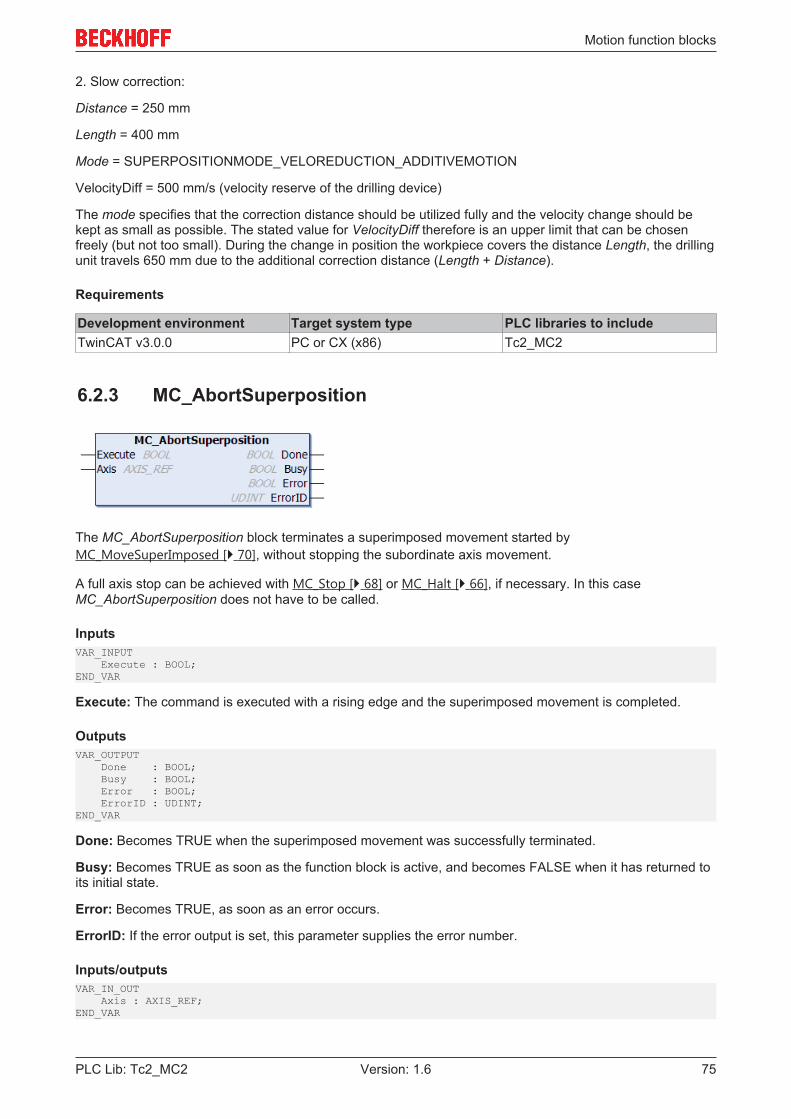
Motion function blocks
PLC Lib: Tc2_MC2 75Version: 1.6
2. Slow correction:
Distance = 250 mm
Length = 400 mm
Mode = SUPERPOSITIONMODE_VELOREDUCTION_ADDITIVEMOTION
VelocityDiff = 500 mm/s (velocity reserve of the drilling device)
The mode specifies that the correction distance should be utilized fully and the velocity change should bekept as small as possible. The stated value for VelocityDiff therefore is an upper limit that can be chosenfreely (but not too small). During the change in position the workpiece covers the distance Length, the drillingunit travels 650 mm due to the additional correction distance (Length + Distance).
Requirements
Development environment Target system type PLC libraries to includeTwinCAT v3.0.0 PC or CX (x86) Tc2_MC2
6.2.3 MC_AbortSuperposition
The MC_AbortSuperposition block terminates a superimposed movement started byMC_MoveSuperImposed [} 70], without stopping the subordinate axis movement.
A full axis stop can be achieved with MC_Stop [} 68] or MC_Halt [} 66], if necessary. In this caseMC_AbortSuperposition does not have to be called.
InputsVAR_INPUT Execute : BOOL;END_VAR
Execute: The command is executed with a rising edge and the superimposed movement is completed.
OutputsVAR_OUTPUT Done : BOOL; Busy : BOOL; Error : BOOL; ErrorID : UDINT; END_VAR
Done: Becomes TRUE when the superimposed movement was successfully terminated.
Busy: Becomes TRUE as soon as the function block is active, and becomes FALSE when it has returned toits initial state.
Error: Becomes TRUE, as soon as an error occurs.
ErrorID: If the error output is set, this parameter supplies the error number.
Inputs/outputsVAR_IN_OUT Axis : AXIS_REF;END_VAR

Motion function blocks
PLC Lib: Tc2_MC276 Version: 1.6
Axis: Axis data structure of the type AXIS_REF [} 91], which uniquely addresses an axis in the system.Among other parameters it contains the current axis status, including position, velocity or error status.
Requirements
Development environment Target system type PLC libraries to includeTwinCAT v3.0.0 PC or CX (x86) Tc2_MC2
6.3 Homing
6.3.1 MC_Home
An axis reference run is carried out with the function block MC_Home.
The referencing mode is set in the TwinCAT System Manager with the encoder parameter Reference Mode.Depending on the connected encoder system, different procedures are possible (see also Referencing modefor incremental encoder)
InputsVAR_INPUT Execute : BOOL; Position : LREAL := DEFAULT_HOME_POSITION; HomingMode : MC_HomingMode; BufferMode : MC_BufferMode; Options : ST_HomingOptions; bCalibrationCam : BOOL; END_VAR
Execute: The command is executed with a rising edge at input Execute.
Position: Absolute reference position to which the axis is set after homing. Alternatively, the constantDEFAULT_HOME_POSITION can be used here. In this case, the Reference position for homing specified inthe TwinCAT System Manager is used. NOTE! Since the reference position is generally set during themotion, the axis will not stop exactly at this position. The standstill position differs by the brakingdistance of the axis, although the calibration is nevertheless exact.
HomingMode: HomingMode [} 105] determines in which way the calibration is carried out.
• MC_DefaultHomingExecutes the standard reference run.
• MC_DirectSets the axis position directly to Position without executing a movement.
• MC_ForceCalibration Enforces status "axis is calibrated". No movement takes place, and the position remains unchanged.
• MC_ResetCalibration Resets the calibration status of the axis. No movement takes place, and the position remainsunchanged.
Motion function blocks
PLC Lib: Tc2_MC2 77Version: 1.6
BufferMode: Currently not implemented - BufferMode [} 102] is analyzed if the axis is already executinganother command. The running command can be aborted, or the new command becomes active after therunning command. The BufferMode also determines the transition condition from the current to the nextcommand.
Options: The data structure option includes additional, rarely required parameters. The input can normallyremain open.
• ClearPositionLag: ClearPositionLag is only active in mode MC_Direct. ClearPositionLag canoptionally be used to set the set and actual positions to the same value. In this case the following erroris cancelled.
bCalibrationCam: bCalibrationCam reflects the signal of a reference cam that may enter the controller via adigital input.
General rules for MC function blocks [} 13]
OutputsVAR_OUTPUT Done : BOOL; Busy : BOOL; Active : BOOL; CommandAborted : BOOL; Error : BOOL; ErrorID : UDINT;END_VAR
Done: The Done output becomes TRUE, if the axis was calibrated and has come to a standstill.
Busy: The Busy output becomes TRUE when the command is started with Execute and remains TRUE aslong as the movement command is processed. If Busy becomes FALSE again, the function block is ready fora new job. At the same time one of the outputs, Done, CommandAborted or Error, is set.
Active: Currently not implemented - Active indicates that the command is running. If the command wasqueued, it becomes active once a running command is completed.
CommandAborted: Becomes TRUE, if the command could not be fully executed.
Error: Becomes TRUE if an error occurs.
ErrorID: If the error output is set, this parameter supplies the error number.
General rules for MC function blocks [} 13]
Inputs/outputsVAR_IN_OUT Axis : AXIS_REF;END_VAR
Axis: Axis data structure of the type AXIS_REF [} 91], which uniquely addresses an axis in the system.Among other parameters it contains the current axis status, including position, velocity or error status.
Note
The referencing process has several phases. The referencing state (calibration state) is signaled in the cyclicinterface of the axis (Axis.NcToPlc.HomingState). The following diagram illustrates the individual processphases after starting of the MC_Home block.
If an axis is to be referenced without reference cam, i.e. only based on the sync pulse of the sensor, thereference cam can be simulated via the PLC program. The bCalibrationCam signal is initially activated andthen cancelled, if Axis.NcToPlc.HomingState [} 92] is equal or greater 4.

Motion function blocks
PLC Lib: Tc2_MC278 Version: 1.6
Requirements
Development environment Target system type PLC libraries to includeTwinCAT v3.0.0 PC or CX (x86) Tc2_MC2
6.4 Manual motion
6.4.1 MC_Jog
The MC_Jog function block enables an axis to be moved via manual keys. The key signal can be linkeddirectly with the JogForward and JogBackwards inputs. The required operating mode is specified via themode input. An inching mode for moving the axis by a specified distance whenever the key is pressed is alsoavailable. The velocity and dynamics of the motion can be specified depending on the mode.
InputsVAR_INPUT JogForward : BOOL; JogBackwards : BOOL; Mode : E_JogMode; Position : LREAL; Velocity : LREAL; Acceleration : LREAL; Deceleration : LREAL; Jerk : LREAL;END_VAR
JogForward: The command is executed with rising edge and the axis moved in positive direction of travel.Depending on the mode the axis moves as long as the signal remains TRUE or stops automatically after aspecified distance. During the motion no further signal edges are accepted (this includes the JogBackwardsinput). If signal edges occur simultaneously at the JogForward and JogBackwards inputs, JogForward haspriority.
Motion function blocks
PLC Lib: Tc2_MC2 79Version: 1.6
JogBackwards: The command is executed with rising edge and the axis moved in negative direction oftravel. JogForward and JogBackwards should be triggered alternatively, although they are also mutuallylocked internally.
Mode: The mode [} 100] input specifies the mode for manual operation.
• MC_JOGMODE_STANDARD_SLOW The axis moves as long as the signal at one of the jog inputs is TRUE. The low velocity for manualfunctions specified in the TwinCAT System Manager and standard dynamics are used. In this mode theposition, velocity and dynamics data specified in the function block have no effect.
• MC_JOGMODE_STANDARD_FAST The axis moves as long as the signal at one of the jog inputs is TRUE. The high velocity for manualfunctions specified in the TwinCAT System Manager and standard dynamics are used. In this mode theposition, velocity and dynamics data specified in the function block have no effect.
• MC_JOGMODE_CONTINOUS The axis moves as long as the signal at one of the jog inputs is TRUE. The velocity and dynamics dataspecified by the user are used. The position has no effect.
• MC_JOGMODE_INCHING With rising edge at one of the jog inputs the axis is moved by a certain distance which is specified viathe position input. The axis stops automatically, irrespective of the state of the jog inputs. A newmovement step is only executed once a further rising edge is encountered. With each start the velocityand dynamics data specified by the user are used.
• MC_JOGMODE_INCHING_MODULOWith rising edge at one of the jog inputs the axis is moved by a certain distance which is specified viathe position input. The axis position will snap to an integer multiple of the position parameter. The axisstops automatically, irrespective of the state of the jog inputs. A new movement step is only executedonce a further rising edge is encountered. With each start the velocity and dynamics data specified bythe user are used.
Position: Relative distance for movements in MC_JOGMODE_INCHING mode.
Velocity: Maximum travel velocity (>0).
Acceleration: Acceleration (≥0). If the value is 0, the standard acceleration from the axis configuration in theSystem Manager is used.
Deceleration: Deceleration (≥0). If the value is 0, the standard deceleration from the axis configuration in theSystem Manager is used.
Jerk: Jerk (≥0). If the value is 0, the standard jerk from the axis configuration in the System Manager is used.
NOTE! The parameters Position, Velocity, Acceleration, Deceleration and Jerk are not used in theoperation modes MC_JOGMODE_STANDARD_SLOW and MC_JOGMODE_STANDARD_FAST and do nothave to be specified.
OutputsVAR_OUTPUT Done : BOOL; Busy : BOOL; CommandAborted : BOOL; Error : BOOL; ErrorID : UDINT;END_VAR
Done: Becomes TRUE if a movement is completed successfully.
Busy: Becomes TRUE as soon as the function block is active, and becomes FALSE when it has returned toits initial state. Only then can a further edge be accepted at the jog inputs.
Active: Indicates that the axis is moved via the jog function.
CommandAborted: Becomes TRUE if the process is interrupted by an external event, e.g. by the call up ofMC_Stop [} 68].
Error: Becomes TRUE if an error occurs.
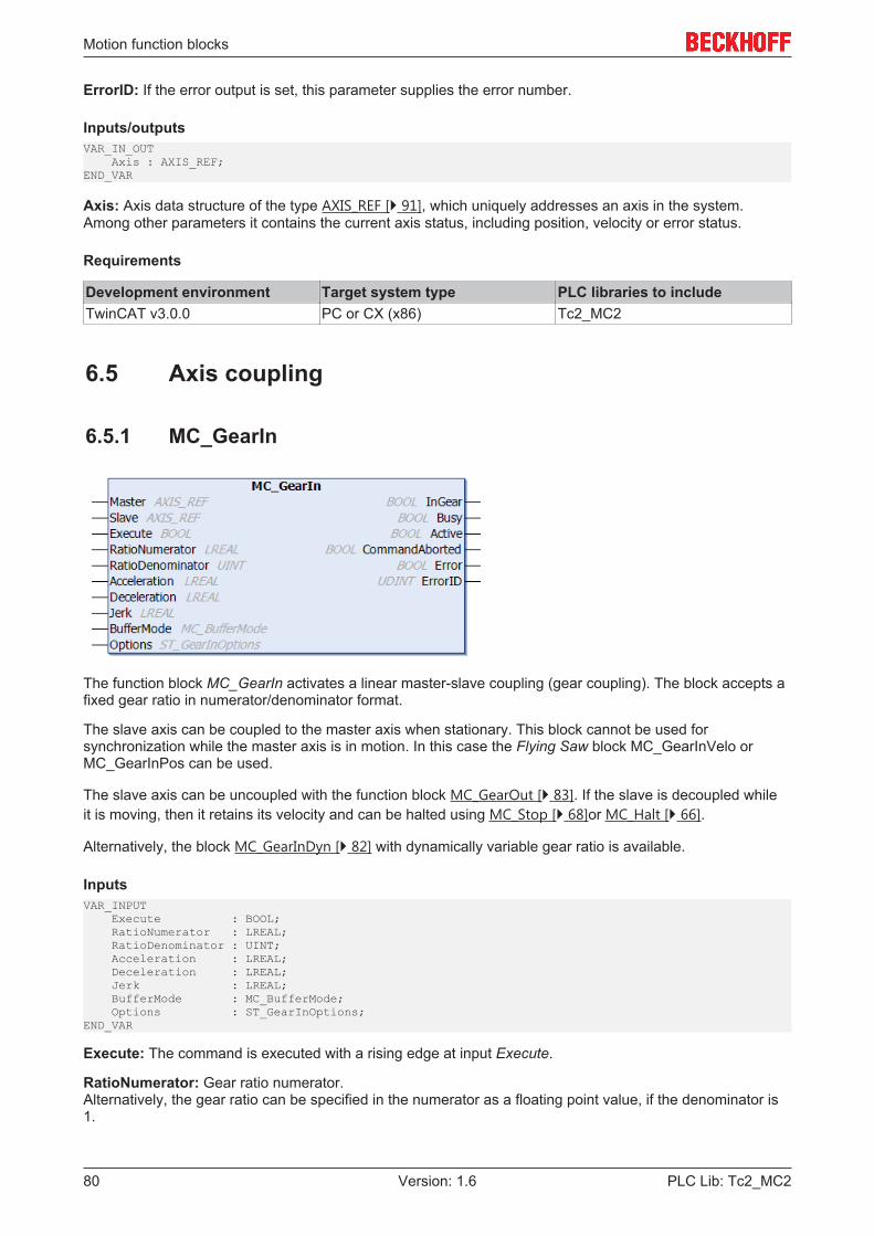
Motion function blocks
PLC Lib: Tc2_MC280 Version: 1.6
ErrorID: If the error output is set, this parameter supplies the error number.
Inputs/outputsVAR_IN_OUT Axis : AXIS_REF;END_VAR
Axis: Axis data structure of the type AXIS_REF [} 91], which uniquely addresses an axis in the system.Among other parameters it contains the current axis status, including position, velocity or error status.
Requirements
Development environment Target system type PLC libraries to includeTwinCAT v3.0.0 PC or CX (x86) Tc2_MC2
6.5 Axis coupling
6.5.1 MC_GearIn
The function block MC_GearIn activates a linear master-slave coupling (gear coupling). The block accepts afixed gear ratio in numerator/denominator format.
The slave axis can be coupled to the master axis when stationary. This block cannot be used forsynchronization while the master axis is in motion. In this case the Flying Saw block MC_GearInVelo orMC_GearInPos can be used.
The slave axis can be uncoupled with the function block MC_GearOut [} 83]. If the slave is decoupled whileit is moving, then it retains its velocity and can be halted using MC_Stop [} 68]or MC_Halt [} 66].
Alternatively, the block MC_GearInDyn [} 82] with dynamically variable gear ratio is available.
InputsVAR_INPUT Execute : BOOL; RatioNumerator : LREAL; RatioDenominator : UINT; Acceleration : LREAL; Deceleration : LREAL; Jerk : LREAL; BufferMode : MC_BufferMode; Options : ST_GearInOptions;END_VAR
Execute: The command is executed with a rising edge at input Execute.
RatioNumerator: Gear ratio numerator.Alternatively, the gear ratio can be specified in the numerator as a floating point value, if the denominator is1.

Motion function blocks
PLC Lib: Tc2_MC2 81Version: 1.6
RatioDenominator: Gear ratio denominator
Acceleration: Acceleration (≥0). (currently not implemented)
Deceleration: Deceleration (≥0). (currently not implemented)
Jerk: Jerk (≥0). (currently not implemented)
BufferMode: Currently not implemented
Options: Currently not implemented
For a 1:4 ratio the RatioNumerator must be 1, the RatioDenominator must be 4. Alternatively, theRatioDenominator may be 1, and the gear ratio can be specified as floating-point number 0.25 underRatioNumerator. The RatioNumerator may be negative.
OutputsVAR_OUTPUT InGear : BOOL; Busy : BOOL; Active : BOOL; CommandAborted : BOOL; Error : BOOL; ErrorID : UDINT;END_VAR
InGear: Becomes TRUE, if the coupling was successful.
Busy: The Busy output becomes TRUE when the command is started with Execute and remains TRUE aslong as the command is processed. If Busy becomes FALSE again, the function block is ready for a new job.At the same time one of the outputs InGear, CommandAborted or Error is set.
Active: Indicates that the command is executed. (currently Active=Busy, see BufferMode)
CommandAborted: Becomes TRUE, if the command could not be fully executed. The axis may havebecome decoupled during the coupling process (simultaneous command execution).
Error: Becomes TRUE if an error occurs.
ErrorID: If the error output is set, this parameter supplies the error number.
Inputs/outputsVAR_IN_OUT Master : AXIS_REF; Slave : AXIS_REF;END_VAR
Master: Master axis data structure.
Slave: Axis data structure of the Slave.
The axis data structure of type AXIS_REF [} 91] addresses an axis uniquely within the system. Among otherparameters it contains the current axis status, including position, velocity or error status.
Requirements
Development environment Target system type PLC libraries to includeTwinCAT v3.0.0 PC or CX (x86) Tc2_MC2
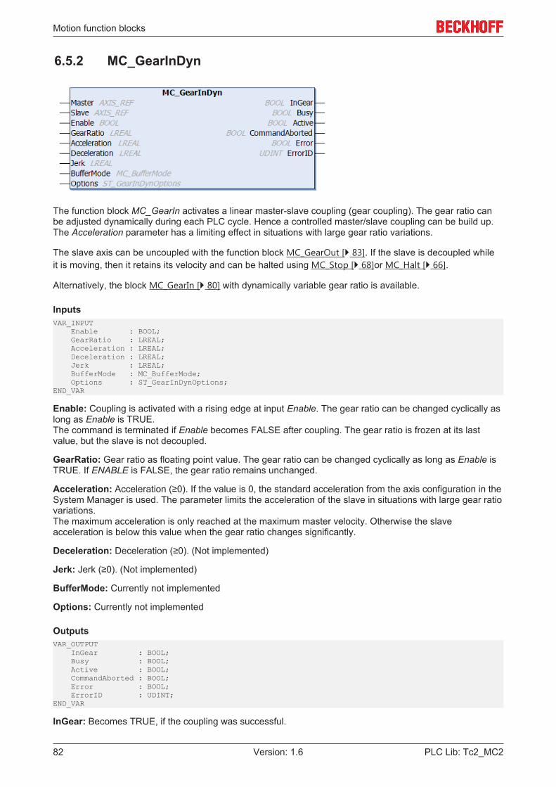
Motion function blocks
PLC Lib: Tc2_MC282 Version: 1.6
6.5.2 MC_GearInDyn
The function block MC_GearIn activates a linear master-slave coupling (gear coupling). The gear ratio canbe adjusted dynamically during each PLC cycle. Hence a controlled master/slave coupling can be build up.The Acceleration parameter has a limiting effect in situations with large gear ratio variations.
The slave axis can be uncoupled with the function block MC_GearOut [} 83]. If the slave is decoupled whileit is moving, then it retains its velocity and can be halted using MC_Stop [} 68]or MC_Halt [} 66].
Alternatively, the block MC_GearIn [} 80] with dynamically variable gear ratio is available.
InputsVAR_INPUT Enable : BOOL; GearRatio : LREAL; Acceleration : LREAL; Deceleration : LREAL; Jerk : LREAL; BufferMode : MC_BufferMode; Options : ST_GearInDynOptions;END_VAR
Enable: Coupling is activated with a rising edge at input Enable. The gear ratio can be changed cyclically aslong as Enable is TRUE.The command is terminated if Enable becomes FALSE after coupling. The gear ratio is frozen at its lastvalue, but the slave is not decoupled.
GearRatio: Gear ratio as floating point value. The gear ratio can be changed cyclically as long as Enable isTRUE. If ENABLE is FALSE, the gear ratio remains unchanged.
Acceleration: Acceleration (≥0). If the value is 0, the standard acceleration from the axis configuration in theSystem Manager is used. The parameter limits the acceleration of the slave in situations with large gear ratiovariations.The maximum acceleration is only reached at the maximum master velocity. Otherwise the slaveacceleration is below this value when the gear ratio changes significantly.
Deceleration: Deceleration (≥0). (Not implemented)
Jerk: Jerk (≥0). (Not implemented)
BufferMode: Currently not implemented
Options: Currently not implemented
OutputsVAR_OUTPUT InGear : BOOL; Busy : BOOL; Active : BOOL; CommandAborted : BOOL; Error : BOOL; ErrorID : UDINT;END_VAR
InGear: Becomes TRUE, if the coupling was successful.
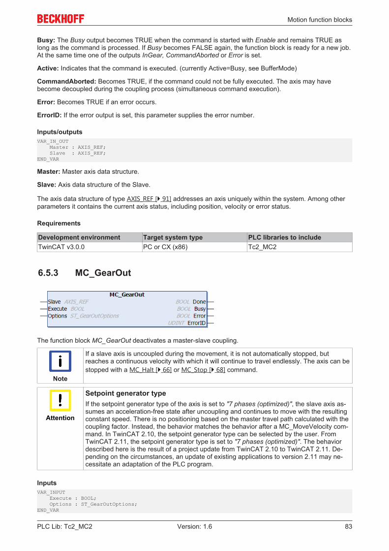
Motion function blocks
PLC Lib: Tc2_MC2 83Version: 1.6
Busy: The Busy output becomes TRUE when the command is started with Enable and remains TRUE aslong as the command is processed. If Busy becomes FALSE again, the function block is ready for a new job.At the same time one of the outputs InGear, CommandAborted or Error is set.
Active: Indicates that the command is executed. (currently Active=Busy, see BufferMode)
CommandAborted: Becomes TRUE, if the command could not be fully executed. The axis may havebecome decoupled during the coupling process (simultaneous command execution).
Error: Becomes TRUE if an error occurs.
ErrorID: If the error output is set, this parameter supplies the error number.
Inputs/outputsVAR_IN_OUT Master : AXIS_REF; Slave : AXIS_REF;END_VAR
Master: Master axis data structure.
Slave: Axis data structure of the Slave.
The axis data structure of type AXIS_REF [} 91] addresses an axis uniquely within the system. Among otherparameters it contains the current axis status, including position, velocity or error status.
Requirements
Development environment Target system type PLC libraries to includeTwinCAT v3.0.0 PC or CX (x86) Tc2_MC2
6.5.3 MC_GearOut
The function block MC_GearOut deactivates a master-slave coupling.
Note
If a slave axis is uncoupled during the movement, it is not automatically stopped, butreaches a continuous velocity with which it will continue to travel endlessly. The axis can bestopped with a MC_Halt [} 66] or MC_Stop [} 68] command.
Attention
Setpoint generator typeIf the setpoint generator type of the axis is set to "7 phases (optimized)", the slave axis as-sumes an acceleration-free state after uncoupling and continues to move with the resultingconstant speed. There is no positioning based on the master travel path calculated with thecoupling factor. Instead, the behavior matches the behavior after a MC_MoveVelocity com-mand. In TwinCAT 2.10, the setpoint generator type can be selected by the user. FromTwinCAT 2.11, the setpoint generator type is set to "7 phases (optimized)". The behaviordescribed here is the result of a project update from TwinCAT 2.10 to TwinCAT 2.11. De-pending on the circumstances, an update of existing applications to version 2.11 may ne-cessitate an adaptation of the PLC program.
InputsVAR_INPUT Execute : BOOL; Options : ST_GearOutOptions;END_VAR
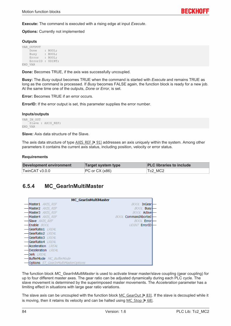
Motion function blocks
PLC Lib: Tc2_MC284 Version: 1.6
Execute: The command is executed with a rising edge at input Execute.
Options: Currently not implemented
OutputsVAR_OUTPUT Done : BOOL; Busy : BOOL; Error : BOOL; ErrorID : UDINT;END_VAR
Done: Becomes TRUE, if the axis was successfully uncoupled.
Busy: The Busy output becomes TRUE when the command is started with Execute and remains TRUE aslong as the command is processed. If Busy becomes FALSE again, the function block is ready for a new job.At the same time one of the outputs, Done or Error, is set.
Error: Becomes TRUE if an error occurs.
ErrorID: If the error output is set, this parameter supplies the error number.
Inputs/outputsVAR_IN_OUT Slave : AXIS_REF;END_VAR
Slave: Axis data structure of the Slave.
The axis data structure of type AXIS_REF [} 91] addresses an axis uniquely within the system. Among otherparameters it contains the current axis status, including position, velocity or error status.
Requirements
Development environment Target system type PLC libraries to includeTwinCAT v3.0.0 PC or CX (x86) Tc2_MC2
6.5.4 MC_GearInMultiMaster
The function block MC_GearInMultiMaster is used to activate linear master/slave coupling (gear coupling) forup to four different master axes. The gear ratio can be adjusted dynamically during each PLC cycle. Theslave movement is determined by the superimposed master movements. The Acceleration parameter has alimiting effect in situations with large gear ratio variations.
The slave axis can be uncoupled with the function block MC_GearOut [} 83]. If the slave is decoupled while itis moving, then it retains its velocity and can be halted using MC_Stop [} 68].
Motion function blocks
PLC Lib: Tc2_MC2 85Version: 1.6
If fewer than four masters are used, an empty data structure can be transferred for parameters Master2 toMaster4 (the axis ID must be 0).
InputsVAR_INPUT Enable : BOOL; GearRatio1 : LREAL; GearRatio2 : LREAL; GearRatio3 : LREAL; GearRatio4 : LREAL; Acceleration : LREAL; Deceleration : LREAL; Jerk : LREAL; BufferMode : MC_BufferMode; Options : ST_GearInMultiMasterOptions;END_VAR
Enable: Coupling is activated with a rising edge at input Enable. The gear ratio can be changed cyclically aslong as Enable is TRUE.The command is terminated if Enable becomes FALSE after coupling. The gear ratio is frozen at its lastvalue, but the slave is not decoupled.
GearRatio1: Gear ratio as floating point value for the first master axis. The gear ratio can be changedcyclically as long as Enable is TRUE. If ENABLE is FALSE, the gear ratio remains unchanged.
GearRatio2: Gear ratio as floating point value for the second master axis. The gear ratio can be changedcyclically as long as Enable is TRUE. If ENABLE is FALSE, the gear ratio remains unchanged.
GearRatio3: Gear ratio as floating point value for the third master axis. The gear ratio can be changedcyclically as long as Enable is TRUE. If ENABLE is FALSE, the gear ratio remains unchanged.
GearRatio4: Gear ratio as floating point value for the fourth master axis. The gear ratio can be changedcyclically as long as Enable is TRUE. If ENABLE is FALSE, the gear ratio remains unchanged.
Acceleration: Acceleration (≥0). If the value is 0, the standard acceleration from the axis configuration in theSystem Manager is used. The parameter limits the acceleration of the slave in situations with large gear ratiovariations.
Deceleration: Deceleration (≥0). If the value is 0, the standard deceleration from the axis configuration in theSystem Manager is used. The parameter limits the deceleration of the slave in situations with large gear ratiovariations. Used only for the option "Advanced Slave Dynamics".
Jerk: Jerk (≥0). If the value is 0, the standard jerk from the axis configuration in the System Manager is used.The parameter limits the jerk of the slave in situations with large gear ratio variations. Used only for theoption "Advanced Slave Dynamics".
BufferMode: Currently not implemented
Options:• AdvancedSlaveDynamics: Exchanges the internal algorithm of the function block. This makes it
possible to synchronise to masters already in motion. Acceleration and deceleration should only beparameterized symmetrically. If jerk presets are too large, this is reduced to the extent that a changefrom zero to the parameterized acceleration / deceleration can take place in one NC cycle. Theresolution of the acceleration / deceleration thus depends directly on the suitable parameterization ofthe jerk value.
OutputsVAR_OUTPUT InGear : BOOL; Busy : BOOL; Active : BOOL; CommandAborted : BOOL; Error : BOOL; ErrorID : UDINT;END_VAR
InGear: Becomes TRUE, if the coupling was successful.
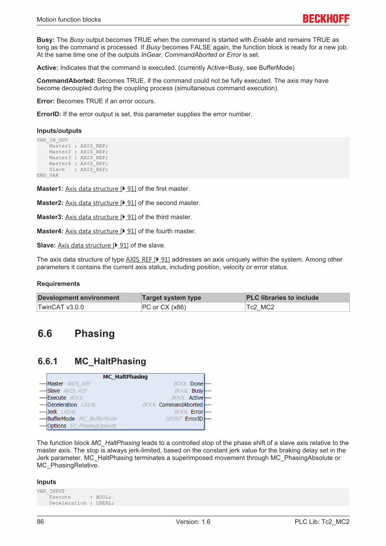
Motion function blocks
PLC Lib: Tc2_MC286 Version: 1.6
Busy: The Busy output becomes TRUE when the command is started with Enable and remains TRUE aslong as the command is processed. If Busy becomes FALSE again, the function block is ready for a new job.At the same time one of the outputs InGear, CommandAborted or Error is set.
Active: Indicates that the command is executed. (currently Active=Busy, see BufferMode)
CommandAborted: Becomes TRUE, if the command could not be fully executed. The axis may havebecome decoupled during the coupling process (simultaneous command execution).
Error: Becomes TRUE if an error occurs.
ErrorID: If the error output is set, this parameter supplies the error number.
Inputs/outputsVAR_IN_OUT Master1 : AXIS_REF; Master2 : AXIS_REF; Master3 : AXIS_REF; Master4 : AXIS_REF; Slave : AXIS_REF;END_VAR
Master1: Axis data structure [} 91] of the first master.
Master2: Axis data structure [} 91] of the second master.
Master3: Axis data structure [} 91] of the third master.
Master4: Axis data structure [} 91] of the fourth master.
Slave: Axis data structure [} 91] of the slave.
The axis data structure of type AXIS_REF [} 91] addresses an axis uniquely within the system. Among otherparameters it contains the current axis status, including position, velocity or error status.
Requirements
Development environment Target system type PLC libraries to includeTwinCAT v3.0.0 PC or CX (x86) Tc2_MC2
6.6 Phasing
6.6.1 MC_HaltPhasing
The function block MC_HaltPhasing leads to a controlled stop of the phase shift of a slave axis relative to themaster axis. The stop is always jerk-limited, based on the constant jerk value for the braking delay set in theJerk parameter. MC_HaltPhasing terminates a superimposed movement through MC_PhasingAbsolute orMC_PhasingRelative.
InputsVAR_INPUT Execute : BOOL; Deceleration : LREAL;
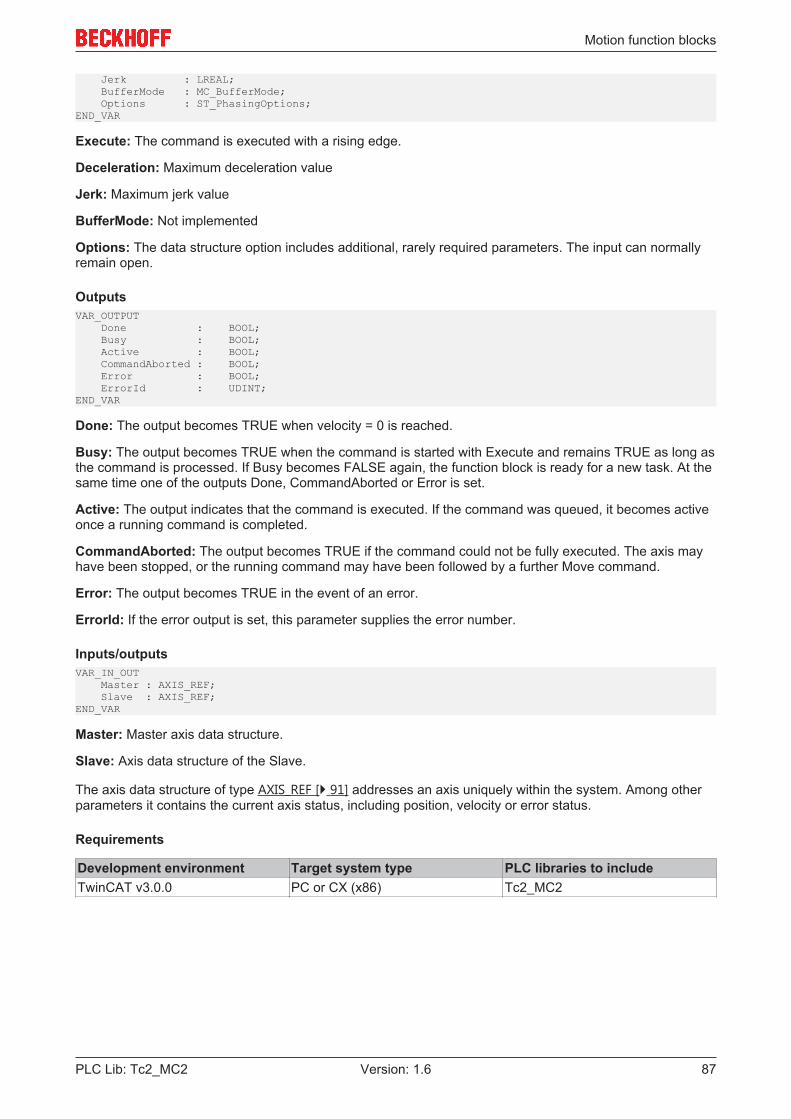
Motion function blocks
PLC Lib: Tc2_MC2 87Version: 1.6
Jerk : LREAL; BufferMode : MC_BufferMode; Options : ST_PhasingOptions;END_VAR
Execute: The command is executed with a rising edge.
Deceleration: Maximum deceleration value
Jerk: Maximum jerk value
BufferMode: Not implemented
Options: The data structure option includes additional, rarely required parameters. The input can normallyremain open.
OutputsVAR_OUTPUT Done : BOOL; Busy : BOOL; Active : BOOL; CommandAborted : BOOL; Error : BOOL; ErrorId : UDINT;END_VAR
Done: The output becomes TRUE when velocity = 0 is reached.
Busy: The output becomes TRUE when the command is started with Execute and remains TRUE as long asthe command is processed. If Busy becomes FALSE again, the function block is ready for a new task. At thesame time one of the outputs Done, CommandAborted or Error is set.
Active: The output indicates that the command is executed. If the command was queued, it becomes activeonce a running command is completed.
CommandAborted: The output becomes TRUE if the command could not be fully executed. The axis mayhave been stopped, or the running command may have been followed by a further Move command.
Error: The output becomes TRUE in the event of an error.
ErrorId: If the error output is set, this parameter supplies the error number.
Inputs/outputsVAR_IN_OUT Master : AXIS_REF; Slave : AXIS_REF;END_VAR
Master: Master axis data structure.
Slave: Axis data structure of the Slave.
The axis data structure of type AXIS_REF [} 91] addresses an axis uniquely within the system. Among otherparameters it contains the current axis status, including position, velocity or error status.
Requirements
Development environment Target system type PLC libraries to includeTwinCAT v3.0.0 PC or CX (x86) Tc2_MC2

Motion function blocks
PLC Lib: Tc2_MC288 Version: 1.6
6.6.2 MC_PhasingAbsolute
The function block MC_PhasingAbsolute can be used to set a phase shift between a master axis and a slaveaxis. The function block executes a superimposed movement of the slave axis, resulting in a positiondifference (PhaseShift) between master and slave.
The dynamic values velocity, acceleration and deceleration refer to the superimposed movement with whichthe phase shift is carried out. The motion is always jerk-limited, based on the constant jerk value set in theJerk parameter. The value applies both for the acceleration and the deceleration.
InputsVAR_INPUT Execute : BOOL; PhaseShift : LREAL; Velocity : LREAL; Acceleration : LREAL; Deceleration : LREAL; Jerk : LREAL; BufferMode : MC_BufferMode; Options : ST_PhasingOptions;END_VAR
Execute: The command is executed with a rising edge.
PhaseShift: Phase shift to be set between master axis and slave axis
Velocity: Maximum velocity that may be reached during the phase shift.
Acceleration: Maximum acceleration value
Deceleration: Maximum deceleration value
Jerk: Maximum jerk value
BufferMode: Not implemented
Options: The data structure option includes additional, rarely required parameters. The input can normallyremain open.
OutputsVAR_OUTPUT Done : BOOL; Busy : BOOL; Active : BOOL; CommandAborted : BOOL; Error : BOOL; ErrorId : UDINT; AbsolutePhaseShift : LREAL;END_VAR
Done: The output becomes TRUE once the absolute phase shift has been reached.
Busy: The output becomes TRUE when the command is started with Execute and remains TRUE as long asthe phase shift is active. If Busy becomes FALSE again, the function block is ready for a new task. At thesame time one of the outputs Done, CommandAborted or Error is set.
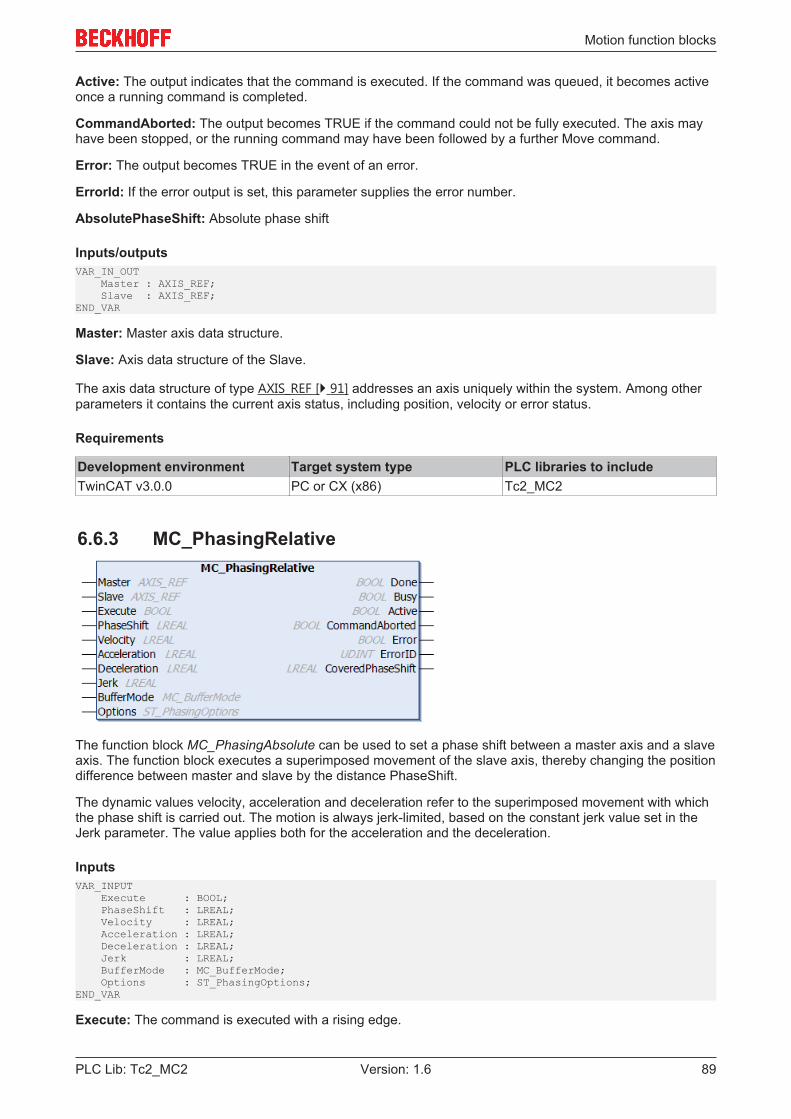
Motion function blocks
PLC Lib: Tc2_MC2 89Version: 1.6
Active: The output indicates that the command is executed. If the command was queued, it becomes activeonce a running command is completed.
CommandAborted: The output becomes TRUE if the command could not be fully executed. The axis mayhave been stopped, or the running command may have been followed by a further Move command.
Error: The output becomes TRUE in the event of an error.
ErrorId: If the error output is set, this parameter supplies the error number.
AbsolutePhaseShift: Absolute phase shift
Inputs/outputsVAR_IN_OUT Master : AXIS_REF; Slave : AXIS_REF;END_VAR
Master: Master axis data structure.
Slave: Axis data structure of the Slave.
The axis data structure of type AXIS_REF [} 91] addresses an axis uniquely within the system. Among otherparameters it contains the current axis status, including position, velocity or error status.
Requirements
Development environment Target system type PLC libraries to includeTwinCAT v3.0.0 PC or CX (x86) Tc2_MC2
6.6.3 MC_PhasingRelative
The function block MC_PhasingAbsolute can be used to set a phase shift between a master axis and a slaveaxis. The function block executes a superimposed movement of the slave axis, thereby changing the positiondifference between master and slave by the distance PhaseShift.
The dynamic values velocity, acceleration and deceleration refer to the superimposed movement with whichthe phase shift is carried out. The motion is always jerk-limited, based on the constant jerk value set in theJerk parameter. The value applies both for the acceleration and the deceleration.
InputsVAR_INPUT Execute : BOOL; PhaseShift : LREAL; Velocity : LREAL; Acceleration : LREAL; Deceleration : LREAL; Jerk : LREAL; BufferMode : MC_BufferMode; Options : ST_PhasingOptions;END_VAR
Execute: The command is executed with a rising edge.
Motion function blocks
PLC Lib: Tc2_MC290 Version: 1.6
PhaseShift: Amount by which the phase shift between master axis and slave axis is changed.
Velocity: Maximum velocity that may be reached during the phase shift.
Acceleration: Maximum acceleration value
Deceleration: Maximum deceleration value
Jerk: Maximum jerk value
BufferMode: Not implemented
Options: The data structure option includes additional, rarely required parameters. The input can normallyremain open.
OutputsVAR_OUTPUT Done : BOOL; Busy : BOOL; Active : BOOL; CommandAborted : BOOL; Error : BOOL; ErrorId : UDINT; CoveredPhaseShift : LREAL;END_VAR
Done: The output becomes TRUE once the relative phase shift has been reached.
Busy: The output becomes TRUE when the command is started with Execute and remains TRUE as long asthe phase shift is active. If Busy becomes FALSE again, the function block is ready for a new task. At thesame time one of the outputs Done, CommandAborted or Error is set.
Active: The output indicates that the command is executed. If the command was queued, it becomes activeonce a running command is completed.
CommandAborted: The output becomes TRUE if the command could not be fully executed. The axis mayhave been stopped, or the running command may have been followed by a further Move command.
Error: The output becomes TRUE in the event of an error.
ErrorId: If the error output is set, this parameter supplies the error number.
CoveredPhaseShift: Relative phase shift
Inputs/outputsVAR_IN_OUT Master : AXIS_REF; Slave : AXIS_REF;END_VAR
Master: Master axis data structure.
Slave: Axis data structure of the Slave.
The axis data structure of type AXIS_REF [} 91] addresses an axis uniquely within the system. Among otherparameters it contains the current axis status, including position, velocity or error status.
Requirements
Development environment Target system type PLC libraries to includeTwinCAT v3.0.0 PC or CX (x86) Tc2_MC2
Data types
PLC Lib: Tc2_MC2 91Version: 1.6
7 Data types
7.1 Axis interface
7.1.1 AXIS_REFThe AXIS_REF data type contains axis information. AXIS_REF is an interface between the PLC and the NC.It is added to MC function blocks as axis reference.
TYPE AXIS_REF :VAR_INPUTPlcToNc AT %Q* : PLCTONC_AXIS_REF;END_VARVAR_OUTPUTNcToPlc AT %I* : NCTOPLC_AXIS_REF;ADS : ST_AdsAddress;Status : ST_AxisStatus;END_VAREND_TYPE
AXIS_REF elements
PlcToNc: PlcToNc [} 98] is a data structure that is cyclically exchanged between PLC and NC. Via this datastructure the MC function blocks communicate with the NC and send control information from the PLC to theNC. This data structure is automatically placed in the output process image of the PLC and must be linked inTwinCAT System Manager with the input process image of an NC axis.
NcToPlc: NcToPlc [} 92] is a data structure that is cyclically exchanged between PLC and NC. Via this datastructure the MC function blocks communicate with the NC and receive status information from the NC. Thisdata structure is automatically placed in the input process image of the PLC and must be linked in TwinCATSystem Manager with the output process image of an NC axis.
The NcToPlc [} 92] structure contains all main state data for an axis such as position, velocity andinstruction state. Since data exchange takes place cyclically, the PLC can access the current axis state atany time without additional communication effort.
ADS: The ADS data structure contains the ADS communication parameters for an axis that are required fordirect ADS communication. Normally this structure does not have to be populated. The user can use it tostored information for controlling an axis on another target system or via a special port number.
Status: The Status data structure [} 110] contains additional or processed status information for an axis. Thisdata structure is not refreshed cyclically, but has to be updated through the PLC program. The easiest wayto achieve this is by calling MC_ReadStatus [} 26] or, alternatively, by calling the action ReadStatus ofAXIS_REF:
Example:VAR Axis1 : AXIS_REF (* axis data structure for Axis-1 *)END_VAR
(* program code at the beginning of each PLC cycle *)Axis1.ReadStatus();
(* alternative program code at the beginning of each PLC cycle *)Axis1();
ReadStatus rsp. Axis1() should be called once at the start of each PLC cycle. The current status informationcan then be accessed in AXIS_REF from the whole PLC program. Within a cycle the status does notchange.
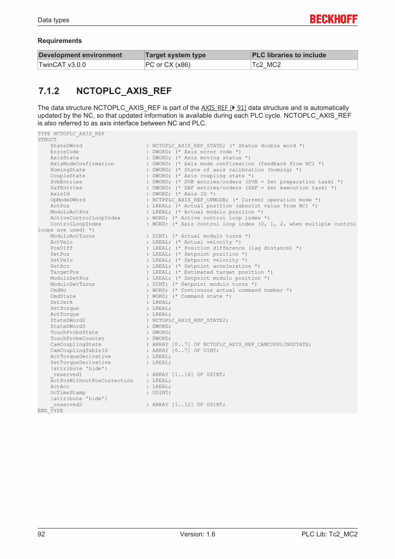
Data types
PLC Lib: Tc2_MC292 Version: 1.6
Requirements
Development environment Target system type PLC libraries to includeTwinCAT v3.0.0 PC or CX (x86) Tc2_MC2
7.1.2 NCTOPLC_AXIS_REFThe data structure NCTOPLC_AXIS_REF is part of the AXIS_REF [} 91] data structure and is automaticallyupdated by the NC, so that updated information is available during each PLC cycle. NCTOPLC_AXIS_REFis also referred to as axis interface between NC and PLC.TYPE NCTOPLC_AXIS_REFSTRUCT StateDWord : NCTOPLC_AXIS_REF_STATE; (* Status double word *) ErrorCode : DWORD; (* Axis error code *) AxisState : DWORD; (* Axis moving status *) AxisModeConfirmation : DWORD; (* Axis mode confirmation (feedback from NC) *) HomingState : DWORD; (* State of axis calibration (homing) *) CoupleState : DWORD; (* Axis coupling state *) SvbEntries : DWORD; (* SVB entries/orders (SVB = Set preparation task) *) SafEntries : DWORD; (* SAF entries/orders (SAF = Set execution task) *) AxisId : DWORD; (* Axis ID *) OpModeDWord : NCTPPLC_AXIS_REF_OPMODE; (* Current operation mode *) ActPos : LREAL; (* Actual position (absolut value from NC) *) ModuloActPos : LREAL; (* Actual modulo position *) ActiveControlLoopIndex : WORD; (* Active control loop index *) ControlLoopIndex : WORD; (* Axis control loop index (0, 1, 2, when multiple controlloops are used) *) ModuloActTurns : DINT; (* Actual modulo turns *) ActVelo : LREAL; (* Actual velocity *) PosDiff : LREAL; (* Position difference (lag distance) *) SetPos : LREAL; (* Setpoint position *) SetVelo : LREAL; (* Setpoint velocity *) SetAcc : LREAL; (* Setpoint acceleration *) TargetPos : LREAL; (* Estimated target position *) ModuloSetPos : LREAL; (* Setpoint modulo position *) ModuloSetTurns : DINT; (* Setpoint modulo turns *) CmdNo : WORD; (* Continuous actual command number *) CmdState : WORD; (* Command state *) SetJerk : LREAL; SetTorque : LREAL; ActTorque : LREAL; StateDWord2 : NCTOPLC_AXIS_REF_STATE2; StateDWord3 : DWORD; TouchProbeState : DWORD; TouchProbeCounter : DWORD; CamCouplingState : ARRAY [0..7] OF NCTOPLC_AXIS_REF_CAMCOUPLINGSTATE; CamCouplingTableID : ARRAY [0..7] OF UINT; ActTorqueDerivative : LREAL; SetTorqueDerivative : LREAL; {attribute 'hide'} _reserved1 : ARRAY [1..16] OF USINT; ActPosWithoutPosCorrection : LREAL; ActAcc : LREAL; DcTimeStamp : UDINT; {attribute 'hide'} _reserved2 : ARRAY [1..12] OF USINT;END_TYPE
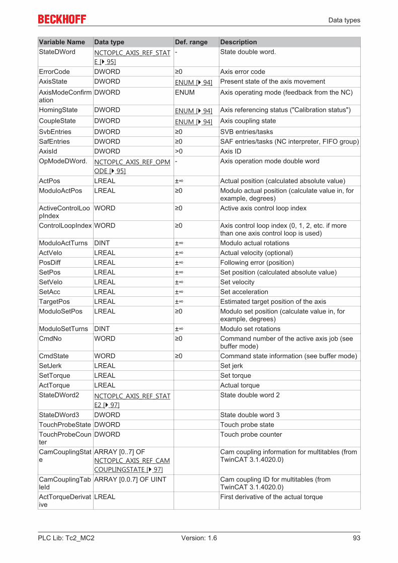
Data types
PLC Lib: Tc2_MC2 93Version: 1.6
Variable Name Data type Def. range DescriptionStateDWord NCTOPLC_AXIS_REF_STAT
E [} 95]- State double word.
ErrorCode DWORD ≥0 Axis error codeAxisState DWORD ENUM [} 94] Present state of the axis movementAxisModeConfirmation
DWORD ENUM Axis operating mode (feedback from the NC)
HomingState DWORD ENUM [} 94] Axis referencing status ("Calibration status")CoupleState DWORD ENUM [} 94] Axis coupling stateSvbEntries DWORD ≥0 SVB entries/tasksSafEntries DWORD ≥0 SAF entries/tasks (NC interpreter, FIFO group)AxisId DWORD >0 Axis IDOpModeDWord. NCTOPLC_AXIS_REF_OPM
ODE [} 95]- Axis operation mode double word
ActPos LREAL ±∞ Actual position (calculated absolute value)ModuloActPos LREAL ≥0 Modulo actual position (calculate value in, for
example, degrees)ActiveControlLoopIndex
WORD ≥0 Active axis control loop index
ControlLoopIndex WORD ≥0 Axis control loop index (0, 1, 2, etc. if morethan one axis control loop is used)
ModuloActTurns DINT ±∞ Modulo actual rotationsActVelo LREAL ±∞ Actual velocity (optional)PosDiff LREAL ±∞ Following error (position)SetPos LREAL ±∞ Set position (calculated absolute value)SetVelo LREAL ±∞ Set velocitySetAcc LREAL ±∞ Set accelerationTargetPos LREAL ±∞ Estimated target position of the axisModuloSetPos LREAL ≥0 Modulo set position (calculate value in, for
example, degrees)ModuloSetTurns DINT ±∞ Modulo set rotationsCmdNo WORD ≥0 Command number of the active axis job (see
buffer mode)CmdState WORD ≥0 Command state information (see buffer mode)SetJerk LREAL Set jerkSetTorque LREAL Set torqueActTorque LREAL Actual torqueStateDWord2 NCTOPLC_AXIS_REF_STAT
E2 [} 97]State double word 2
StateDWord3 DWORD State double word 3TouchProbeState DWORD Touch probe stateTouchProbeCounter
DWORD Touch probe counter
CamCouplingState
ARRAY [0..7] OFNCTOPLC_AXIS_REF_CAMCOUPLINGSTATE [} 97]
Cam coupling information for multitables (fromTwinCAT 3.1.4020.0)
CamCouplingTableId
ARRAY [0.0.7] OF UINT Cam coupling ID for multitables (fromTwinCAT 3.1.4020.0)
ActTorqueDerivative
LREAL First derivative of the actual torque
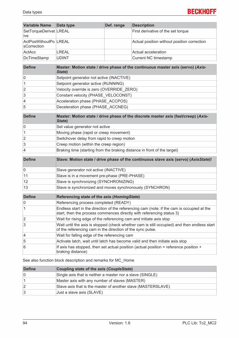
Data types
PLC Lib: Tc2_MC294 Version: 1.6
Variable Name Data type Def. range DescriptionSetTorqueDerivative
LREAL First derivative of the set torque
ActPosWithoutPosCorrection
LREAL Actual position without position correction
ActAcc LREAL Actual accelerationDcTimeStamp UDINT Current NC timestamp
Define Master: Motion state / drive phase of the continuous master axis (servo) (Axis-State)
0 Setpoint generator not active (INACTIVE)1 Setpoint generator active (RUNNING)2 Velocity override is zero (OVERRIDE_ZERO)3 Constant velocity (PHASE_VELOCONST)4 Acceleration phase (PHASE_ACCPOS)5 Deceleration phase (PHASE_ACCNEG)
Define Master: Motion state / drive phase of the discrete master axis (fast/creep) (Axis-State)
0 Set value generator not active1 Moving phase (rapid or creep movement)2 Switchover delay from rapid to creep motion3 Creep motion (within the creep region)4 Braking time (starting from the braking distance in front of the target)
Define Slave: Motion state / drive phase of the continuous slave axis (servo) (AxisState)!
0 Slave generator not active (INACTIVE)11 Slave is in a movement pre-phase (PRE-PHASE)12 Slave is synchronizing (SYNCHRONIZING)13 Slave is synchronized and moves synchronously (SYNCHRON)
Define Referencing state of the axis (HomingState)0 Referencing process completed (READY)1 Endless start in the direction of the referencing cam (note: if the cam is occupied at the
start, then the process commences directly with referencing status 3)2 Wait for rising edge of the referencing cam and initiate axis stop3 Wait until the axis is stopped (check whether cam is still occupied) and then endless start
of the referencing cam in the direction of the sync pulse.4 Wait for falling edge of the referencing cam5 Activate latch, wait until latch has become valid and then initiate axis stop6 If axis has stopped, then set actual position (actual position = reference position +
braking distance)
See also function block description and remarks for MC_Home
Define Coupling state of the axis (CoupleState)0 Single axis that is neither a master nor a slave (SINGLE)1 Master axis with any number of slaves (MASTER)2 Slave axis that is the master of another slave (MASTERSLAVE)3 Just a slave axis (SLAVE)
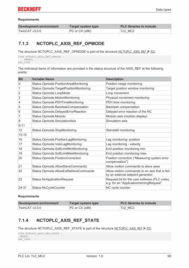
Data types
PLC Lib: Tc2_MC2 95Version: 1.6
Requirements
Development environment Target system type PLC libraries to includeTwinCAT v3.0.0 PC or CX (x86) Tc2_MC2
7.1.3 NCTOPLC_AXIS_REF_OPMODEThe structure NCTOPLC_AXIS_REF_OPMODE is part of the structure NCTOPLC_AXIS_REF [} 92].TYPE NCTOPLC_AXIS_REF_OPMODE : DWORD;END_TYPE
The individual items of information are provided in the status structure of the AXIS_REF at the followingpoints:
Bit Variable Name Description0 Status.Opmode.PositionAreaMonitoring Position range monitoring1 Status.Opmode.TargetPositionMonitoring Target position window monitoring2 Status.Opmode.LoopMode Loop movement3 Status.Opmode.MotionMonitoring Physical movement monitoring4 Status.Opmode.PEHTimeMonitoring PEH time monitoring5 Status.Opmode.BacklashCompensation Backlash compensation6 Status.Opmode.DelayedErrorReaction Delayed error reaction of the NC7 Status.Opmode.Modulo Modulo axis (modulo display)8 Status.Opmode.SimulationAxis Simulation axis9-1112 Status.Opmode.StopMonitoring Standstill monitoring13-1516 Status.Opmode.PositionLagMonitoring Lag monitoring- position17 Status.Opmode.VeloLagMonitoring Lag monitoring - velocity18 Status.Opmode.SoftLimitMinMonitoring End position monitoring min.19 Status.Opmode.SoftLimitMaxMonitoring End position monitoring max.20 Status.Opmode.PositionCorrection Position correction ("Measuring system error
compensation")21 Status.Opmode.AllowSlaveCommands Allow motion commands to slave axes22 Status.Opmode.AllowExtSetAxisCommands Allow motion commands to an axis that is fed
by an external setpoint generator.23 Status.NcApplicationRequest Request bit for the user software (PLC code),
e.g. for an "ApplicationHomingRequest"24-31 Status.NcCycleCounter NC cycle counter
Requirements
Development environment Target system type PLC libraries to includeTwinCAT v3.0.0 PC or CX (x86) Tc2_MC2
7.1.4 NCTOPLC_AXIS_REF_STATEThe structure NCTOPLC_AXIS_REF_STATE is part of the structure NCTOPLC_AXIS_REF [} 92].TYPE NCTOPLC_AXIS_REF_STATE : DWORD;END_TYPE
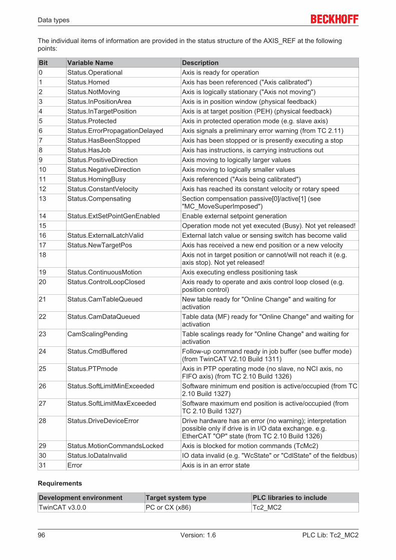
Data types
PLC Lib: Tc2_MC296 Version: 1.6
The individual items of information are provided in the status structure of the AXIS_REF at the followingpoints:
Bit Variable Name Description0 Status.Operational Axis is ready for operation1 Status.Homed Axis has been referenced ("Axis calibrated")2 Status.NotMoving Axis is logically stationary ("Axis not moving")3 Status.InPositionArea Axis is in position window (physical feedback)4 Status.InTargetPosition Axis is at target position (PEH) (physical feedback)5 Status.Protected Axis in protected operation mode (e.g. slave axis)6 Status.ErrorPropagationDelayed Axis signals a preliminary error warning (from TC 2.11)7 Status.HasBeenStopped Axis has been stopped or is presently executing a stop8 Status.HasJob Axis has instructions, is carrying instructions out9 Status.PositiveDirection Axis moving to logically larger values10 Status.NegativeDirection Axis moving to logically smaller values11 Status.HomingBusy Axis referenced ("Axis being calibrated")12 Status.ConstantVelocity Axis has reached its constant velocity or rotary speed13 Status.Compensating Section compensation passive[0]/active[1] (see
"MC_MoveSuperImposed")14 Status.ExtSetPointGenEnabled Enable external setpoint generation15 Operation mode not yet executed (Busy). Not yet released!16 Status.ExternalLatchValid External latch value or sensing switch has become valid17 Status.NewTargetPos Axis has received a new end position or a new velocity18 Axis not in target position or cannot/will not reach it (e.g.
axis stop). Not yet released!19 Status.ContinuousMotion Axis executing endless positioning task20 Status.ControlLoopClosed Axis ready to operate and axis control loop closed (e.g.
position control)21 Status.CamTableQueued New table ready for "Online Change" and waiting for
activation22 Status.CamDataQueued Table data (MF) ready for "Online Change" and waiting for
activation23 CamScalingPending Table scalings ready for "Online Change" and waiting for
activation24 Status.CmdBuffered Follow-up command ready in job buffer (see buffer mode)
(from TwinCAT V2.10 Build 1311)25 Status.PTPmode Axis in PTP operating mode (no slave, no NCI axis, no
FIFO axis) (from TC 2.10 Build 1326)26 Status.SoftLimitMinExceeded Software minimum end position is active/occupied (from TC
2.10 Build 1327)27 Status.SoftLimitMaxExceeded Software maximum end position is active/occupied (from
TC 2.10 Build 1327)28 Status.DriveDeviceError Drive hardware has an error (no warning); interpretation
possible only if drive is in I/O data exchange. e.g.EtherCAT "OP" state (from TC 2.10 Build 1326)
29 Status.MotionCommandsLocked Axis is blocked for motion commands (TcMc2)30 Status.IoDataInvalid IO data invalid (e.g. "WcState" or "CdlState" of the fieldbus)31 Error Axis is in an error state
Requirements
Development environment Target system type PLC libraries to includeTwinCAT v3.0.0 PC or CX (x86) Tc2_MC2
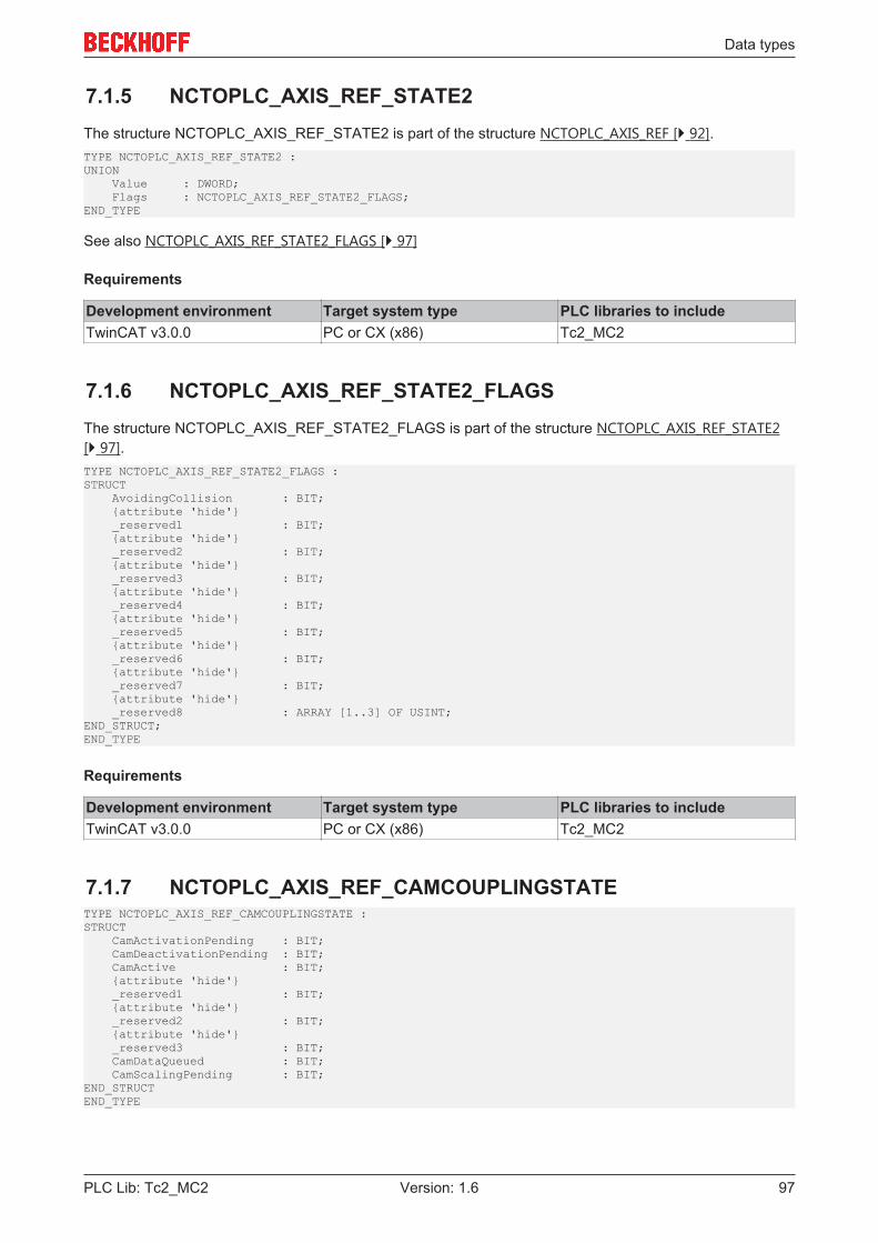
Data types
PLC Lib: Tc2_MC2 97Version: 1.6
7.1.5 NCTOPLC_AXIS_REF_STATE2The structure NCTOPLC_AXIS_REF_STATE2 is part of the structure NCTOPLC_AXIS_REF [} 92].TYPE NCTOPLC_AXIS_REF_STATE2 :UNION Value : DWORD; Flags : NCTOPLC_AXIS_REF_STATE2_FLAGS;END_TYPE
See also NCTOPLC_AXIS_REF_STATE2_FLAGS [} 97]
Requirements
Development environment Target system type PLC libraries to includeTwinCAT v3.0.0 PC or CX (x86) Tc2_MC2
7.1.6 NCTOPLC_AXIS_REF_STATE2_FLAGSThe structure NCTOPLC_AXIS_REF_STATE2_FLAGS is part of the structure NCTOPLC_AXIS_REF_STATE2[} 97].TYPE NCTOPLC_AXIS_REF_STATE2_FLAGS :STRUCT AvoidingCollision : BIT; {attribute 'hide'} _reserved1 : BIT; {attribute 'hide'} _reserved2 : BIT; {attribute 'hide'} _reserved3 : BIT; {attribute 'hide'} _reserved4 : BIT; {attribute 'hide'} _reserved5 : BIT; {attribute 'hide'} _reserved6 : BIT; {attribute 'hide'} _reserved7 : BIT; {attribute 'hide'} _reserved8 : ARRAY [1..3] OF USINT;END_STRUCT;END_TYPE
Requirements
Development environment Target system type PLC libraries to includeTwinCAT v3.0.0 PC or CX (x86) Tc2_MC2
7.1.7 NCTOPLC_AXIS_REF_CAMCOUPLINGSTATETYPE NCTOPLC_AXIS_REF_CAMCOUPLINGSTATE :STRUCT CamActivationPending : BIT; CamDeactivationPending : BIT; CamActive : BIT; {attribute 'hide'} _reserved1 : BIT; {attribute 'hide'} _reserved2 : BIT; {attribute 'hide'} _reserved3 : BIT; CamDataQueued : BIT; CamScalingPending : BIT;END_STRUCTEND_TYPE
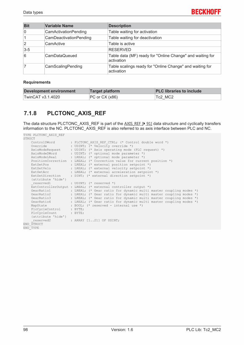
Data types
PLC Lib: Tc2_MC298 Version: 1.6
Bit Variable Name Description0 CamActivationPending Table waiting for activation1 CamDeactivationPending Table waiting for deactivation2 CamActive Table is active3-5 RESERVED6 CamDataQueued Table data (MF) ready for "Online Change" and waiting for
activation7 CamScalingPending Table scalings ready for "Online Change" and waiting for
activation
Requirements
Development environment Target platform PLC libraries to includeTwinCAT v3.1.4020 PC or CX (x86) Tc2_MC2
7.1.8 PLCTONC_AXIS_REFThe data structure PLCTONC_AXIS_REF is part of the AXIS_REF [} 91] data structure and cyclically transfersinformation to the NC. PLCTONC_AXIS_REF is also referred to as axis interface between PLC and NC.TYPE PLCTONC_AXIS_REFSTRUCT ControlDWord : PLCTONC_AXIS_REF_CTRL; (* Control double word *) Override : UDINT; (* Velocity override *) AxisModeRequest : UDINT; (* Axis operating mode (PLC request) *) AxisModeDWord : UDINT; (* optional mode parameter *) AxisModeLReal : LREAL; (* optional mode parameter *) PositionCorrection : LREAL; (* Correction value for current position *) ExtSetPos : LREAL; (* external position setpoint *) ExtSetVelo : LREAL; (* external velocity setpoint *) ExtSetAcc : LREAL; (* external acceleration setpoint *) ExtSetDirection : DINT; (* external direction setpoint *) {attribute 'hide'} _reserved1 : UDINT; (* reserved *) ExtControllerOutput : LREAL; (* external controller output *) GearRatio1 : LREAL; (* Gear ratio for dynamic multi master coupling modes *) GearRatio2 : LREAL; (* Gear ratio for dynamic multi master coupling modes *) GearRatio3 : LREAL; (* Gear ratio for dynamic multi master coupling modes *) GearRatio4 : LREAL; (* Gear ratio for dynamic multi master coupling modes *) MapState : BOOL; (* reserved - internal use *) PlcCycleControl : BYTE; PlcCycleCount : BYTE; {attribute 'hide'} _reserved2 : ARRAY [1..21] OF USINT;END_STRUCTEND_TYPE

Data types
PLC Lib: Tc2_MC2 99Version: 1.6
Variable Name Data type Def. range DescriptionControlDWord PLCTONC_AXSI_REF_CTR
L [} 99]0/1 Control double word
Override UDINT 0...1000000 Velocity override (0% to 100%)AxisModeRequest
UDINT Axis operating mode. Only provided forinternal use!
AxisModeDWord
UDINT Only provided for internal use!
AxisModeLReal LREAL Only provided for internal use!PositionCorrection
LREAL Actual position correction value
ExtSetPos LREAL External set positionExtSetVelo LREAL External set velocityExtSetAcc LREAL External set accelerationExtSetDirection DINT External set travel direction [-1,0,1]ExtControllerOutput
LREAL External controller output. Not yet released!
GearRatio1 LREAL ±∞ Gear ratio (coupling factor) 1GearRatio2 LREAL ±∞ Gear ratio (coupling factor) 2GearRatio3 LREAL ±∞ Gear ratio (coupling factor) 3GearRatio4 LREAL ±∞ Gear ratio (coupling factor) 4MapState BOOL Internal use onlyPlcCycleControl BYTE Internal use onlyPlcCycleCount BYTE Internal use only
Requirements
Development environment Target system type PLC libraries to includeTwinCAT v3.0.0 PC or CX (x86) Tc2_MC2
7.1.9 PLCTONC_AXIS_REF_CTRLThe structure PLCTONC_AXIS_REF_CTRL is part of the structure NCTOPLC_AXIS_REF [} 98].TYPE PLCTONC_AXIS_REF_CTRL : DWORD;END_TYPE
Bit Variable Name Description0 Enable Enable controller1 FeedEnablePlus Feed enable plus2 FeedEnableMinus Feed enable minus3-4 - RESERVED5 HomingSensor Referencing cam or referencing sensor6-7 - RESERVED8 AcceptBlockedDrive Accept blocking of the drive setpoint adoption (e.g. hardware end
positions)from TwinCAT V2.10, Build 1311
9 BlockedDriveDetected User signal Axis is blocked (e.g. mechanical fixed stop).Not yet released!
10-29 - RESERVED30 PlcDebugFlag PLC debug function. For internal use only!
Data types
PLC Lib: Tc2_MC2100 Version: 1.6
Requirements
Development environment Target system type PLC libraries to includeTwinCAT v3.0.0 PC or CX (x86) Tc2_MC2
7.2 Motion function blocks
7.2.1 E_JogModeThe data type E_JogMode is used in conjunction with the function block MC_Jog [} 78].
TYPE E_JogMode :(MC_JOGMODE_STANDARD_SLOW, (* motion with standard jog parameters for slow motion *)MC_JOGMODE_STANDARD_FAST, (* motion with standard jog parameters for fast motion *)MC_JOGMODE_CONTINOUS, (* axis moves as long as the jog button is pressed using parameterized dynam-ics *)MC_JOGMODE_INCHING, (* axis moves for a certain relative distance *)MC_JOGMODE_INCHING_MODULO (* axis moves for a certain relative distance - stop position is roundedto the distance value *));END_TYPE
Requirements
Development environment Target system type PLC libraries to includeTwinCAT v3.0.0 PC or CX (x86) Tc2_MC2
7.2.2 E_SuperpositionModeTYPE E_SuperpositionMode :(SUPERPOSITIONMODE_VELOREDUCTION_ADDITIVEMOTION := 1,SUPERPOSITIONMODE_VELOREDUCTION_LIMITEDMOTION,SUPERPOSITIONMODE_LENGTHREDUCTION_ADDITIVEMOTION,SUPERPOSITIONMODE_LENGTHREDUCTION_LIMITEDMOTION,SUPERPOSITIONMODE_ACCREDUCTION_ADDITIVEMOTION, (from TwinCAT2.11)SUPERPOSITIONMODE_ACCREDUCTION_LIMITEDMOTION (from TwinCAT2.11));END_TYPE
E_SuperpositionMode determines how a superimposed motion is carried out with the function blockMC_MoveSuperImposed [} 70].
The modes referred to as Veloreduction execute a superimposed movement with minimum velocity change,preferentially over the full parameterized compensation section. Conversely, the modes referred to asLengthreduction use the maximum possible velocity and therefore reduce the required distance. In bothcases same distance is compensated.
In cases referred to as Additivemotion, the superimposed axis executes a longer or shorter movement thanindicated by Length, with the difference described by Distance. These modes are used, for example, if theLength parameter refers to a reference axis and the superimposed axis may move by a longer or shorterdistance in comparison.
In cases referred to as Limitedmotion, the superposition is completed within the parameterized distance.These modes are used, for example, if the Length parameter refers to the superimposed axis itself. Withthese modes it should be noted that the superimposed Distance must be significantly shorter than theavailable Length.
SUPERPOSITIONMODE_VELOREDUCTION_ADDITIVEMOTION:
Data types
PLC Lib: Tc2_MC2 101Version: 1.6
The superimposed motion takes place over the whole Length. The specified maximum change in velocityVelocityDiff is reduced in order to reach the required Distance over this length.
The Length is based on a reference axis without superimposed motion (e.g. master axis). The travel path ofthe axis affected by this compensation is Length + Distance.
SUPERPOSITIONMODE_VELOREDUCTION_LIMITEDMOTION:
The superimposed motion takes place over the whole Length. The specified maximum change in velocityVelocityDiff is reduced in order to reach the required Distance over this length.
The Length refers to the axis affected by the compensation. During compensation, the travel path of this axisis Length.
SUPERPOSITIONMODE_LENGTHREDUCTION_ADDITIVEMOTION:
The distance of the superimposed motion is as short as possible and the speed is as high as possible.Although neither the maximum velocity change VelocityDiff or the maximum Length are exceeded.
The Length is based on a reference axis without superimposed motion (e.g. master axis). The maximumtravel path of the axis affected by this compensation is Length + Distance.
SUPERPOSITIONMODE_LENGTHREDUCTION_LIMITEDMOTION:
The distance of the superimposed motion is as short as possible and the speed is as high as possible.Although neither the maximum velocity change VelocityDiff or the maximum Length are exceeded.
The Length refers to the axis affected by the compensation. During compensation, the maximum travel pathof this axis is Length.
SUPERPOSITIONMODE_ACCREDUCTION_ADDITIVEMOTION (from TwinCAT 2.11)
The superimposed motion takes place over the whole Length. The specified maximum acceleration(parameter Acceleration or Deceleration) is reduced as far as possible, in order to reach the specifiedDistance on this path.
The Length is based on a reference axis without superimposed motion (e.g. master axis). The travel path ofthe axis affected by this compensation is Length + Distance.
SUPERPOSITIONMODE_ACCREDUCTION_LIMITEDMOTION (from TwinCAT 2.11)
The superimposed motion takes place over the whole Length. The specified maximum acceleration(parameter Acceleration or Deceleration) is reduced as far as possible, in order to reach the specifiedDistance on this path.
The Length refers to the axis affected by the compensation. During compensation, the travel path of this axisis Length.
Requirements
Development environment Target system type PLC libraries to includeTwinCAT v3.0.0 PC or CX (x86) Tc2_MC2
7.2.3 MC_AxisStatesThe data type MC_AxisStates describes the operating states according to the PlcOpen state diagram [} 10].
TYPE MC_AxisStates :(MC_AXISSTATE_UNDEFINED,MC_AXISSTATE_DISABLED,MC_AXISSTATE_STANDSTILL,MC_AXISSTATE_ERRORSTOP,MC_AXISSTATE_STOPPING,MC_AXISSTATE_HOMING,MC_AXISSTATE_DISCRETEMOTION,MC_AXISSTATE_CONTINOUSMOTION,

Data types
PLC Lib: Tc2_MC2102 Version: 1.6
MC_AXISSTATE_SYNCHRONIZEDMOTION);END_TYPE
See also: General rules for MC function blocks [} 13]
Requirements
Development environment Target system type PLC libraries to includeTwinCAT v3.0.0 PC or CX (x86) Tc2_MC2
7.2.4 MC_BufferModeThe data type MC_BufferMode is used with various function blocks from the motion control library.BufferMode is used to specify how successive travel commands are to be processed.
TYPE MC_BufferMode :(MC_Aborting,MC_Buffered,MC_BlendingLow,MC_BlendingPrevious,MC_BlendingNext,MC_BlendingHigh);END_TYPE
See also: BufferMode in the section on general rules for MC function blocks [} 13]
NOTE! A second function block is required to use the buffer mode. It is not possible to trigger amove block with new parameters while it is active.
Samples:
In the following example, a move command is used to move an axis from position P0 to P1 and then to P2.The second command is issued during the movement to P1, but before the braking ramp with different buffermodes. The reference point for the different velocity profiles is always P1. The mode specifies the velocity v1or v2 at this point.
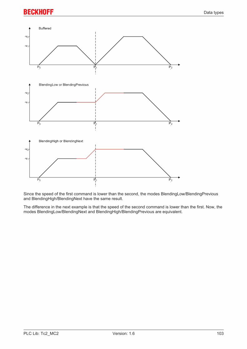
Data types
PLC Lib: Tc2_MC2 103Version: 1.6
Since the speed of the first command is lower than the second, the modes BlendingLow/BlendingPreviousand BlendingHigh/BlendingNext have the same result.
The difference in the next example is that the speed of the second command is lower than the first. Now, themodes BlendingLow/BlendingNext and BlendingHigh/BlendingPrevious are equivalent.

Data types
PLC Lib: Tc2_MC2104 Version: 1.6
The velocity profiles described here assume that the following command is issued in time, i.e. before thebraking ramp of the first command. Otherwise, blending is implemented as best as possible.
Requirements
Development environment Target system type PLC libraries to includeTwinCAT v3.0.0 PC or CX (x86) Tc2_MC2
7.2.5 MC_DirectionTYPE MC_Direction :(MC_Positive_Direction := 1,MC_Shortest_Way ,MC_Negative_Direction,MC_Current_Direction);END_TYPE
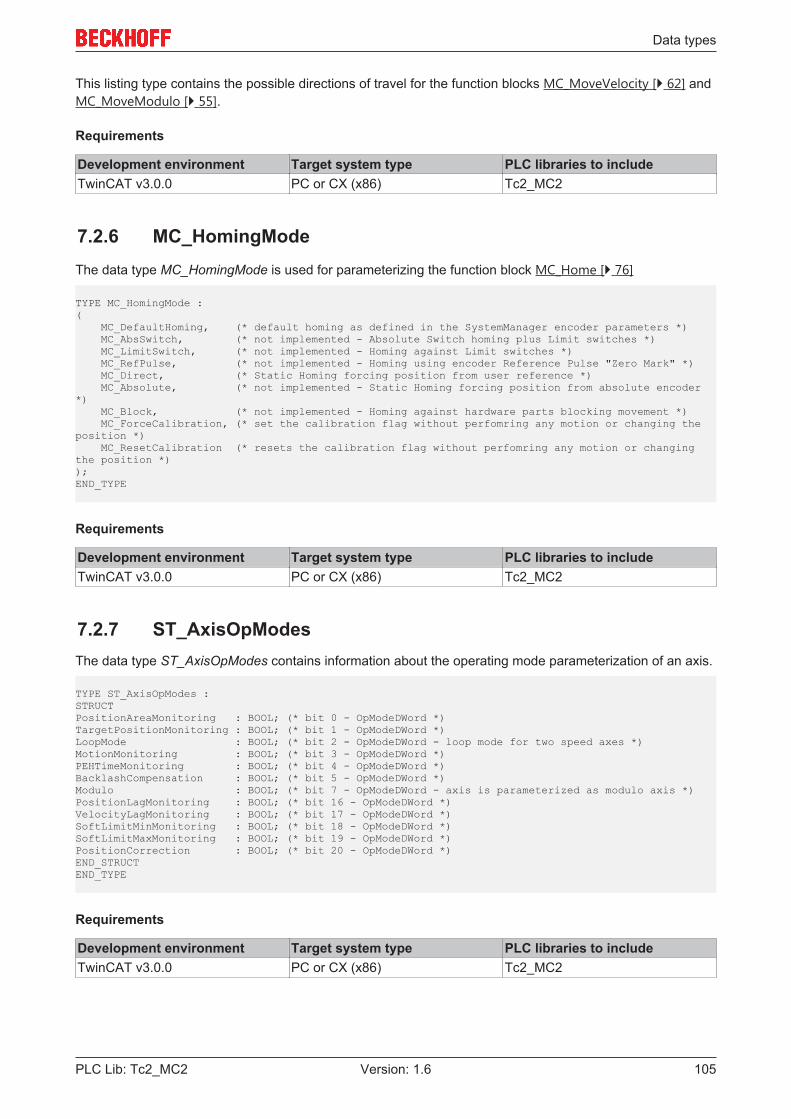
Data types
PLC Lib: Tc2_MC2 105Version: 1.6
This listing type contains the possible directions of travel for the function blocks MC_MoveVelocity [} 62] andMC_MoveModulo [} 55].
Requirements
Development environment Target system type PLC libraries to includeTwinCAT v3.0.0 PC or CX (x86) Tc2_MC2
7.2.6 MC_HomingModeThe data type MC_HomingMode is used for parameterizing the function block MC_Home [} 76]
TYPE MC_HomingMode :( MC_DefaultHoming, (* default homing as defined in the SystemManager encoder parameters *) MC_AbsSwitch, (* not implemented - Absolute Switch homing plus Limit switches *) MC_LimitSwitch, (* not implemented - Homing against Limit switches *) MC_RefPulse, (* not implemented - Homing using encoder Reference Pulse "Zero Mark" *) MC_Direct, (* Static Homing forcing position from user reference *) MC_Absolute, (* not implemented - Static Homing forcing position from absolute encoder*) MC_Block, (* not implemented - Homing against hardware parts blocking movement *) MC_ForceCalibration, (* set the calibration flag without perfomring any motion or changing theposition *) MC_ResetCalibration (* resets the calibration flag without perfomring any motion or changingthe position *));END_TYPE
Requirements
Development environment Target system type PLC libraries to includeTwinCAT v3.0.0 PC or CX (x86) Tc2_MC2
7.2.7 ST_AxisOpModesThe data type ST_AxisOpModes contains information about the operating mode parameterization of an axis.
TYPE ST_AxisOpModes :STRUCTPositionAreaMonitoring : BOOL; (* bit 0 - OpModeDWord *)TargetPositionMonitoring : BOOL; (* bit 1 - OpModeDWord *)LoopMode : BOOL; (* bit 2 - OpModeDWord - loop mode for two speed axes *)MotionMonitoring : BOOL; (* bit 3 - OpModeDWord *)PEHTimeMonitoring : BOOL; (* bit 4 - OpModeDWord *)BacklashCompensation : BOOL; (* bit 5 - OpModeDWord *)Modulo : BOOL; (* bit 7 - OpModeDWord - axis is parameterized as modulo axis *)PositionLagMonitoring : BOOL; (* bit 16 - OpModeDWord *)VelocityLagMonitoring : BOOL; (* bit 17 - OpModeDWord *)SoftLimitMinMonitoring : BOOL; (* bit 18 - OpModeDWord *)SoftLimitMaxMonitoring : BOOL; (* bit 19 - OpModeDWord *)PositionCorrection : BOOL; (* bit 20 - OpModeDWord *)END_STRUCTEND_TYPE
Requirements
Development environment Target system type PLC libraries to includeTwinCAT v3.0.0 PC or CX (x86) Tc2_MC2

Data types
PLC Lib: Tc2_MC2106 Version: 1.6
7.2.8 ST_SuperpositionOptionsTYPE ST_SuperpositionOptions :STRUCT AbortOption : E_SuperpositionAbortOption;END_STRUCTEND_TYPE
TYPE E_SuperpositionAbortOption : ( SUPERPOSITIONOPTION_ABORTATSTANDSTILL := 0, SUPERPOSITIONOPTION_RESUMEAFTERSTANDSTILL, SUPERPOSITIONOPTION_RESUMEAFTERMOTIONSTOP );END_TYPE
AbortOption
AbortOption is an optional parameter of the MC_MoveSuperimposed [} 70] block that specifies the behaviorof a superimposed movement in the case of a standstill of the main movement.
SUPERPOSITIONOPTION_ABORTATSTANDSTILL:
The superimposed movement is aborted as soon as the subordinate movement leads to a standstill of theaxis. The only exception to this is a standstill caused by a speed override of zero. In this case thesuperimposed movement is also continued as soon as the override is not equal to zero. AbortAtStandstill isthe standard behavior if the option is not assigned by the user.
SUPERPOSITIONOPTION_RESUMEAFTERSTANDSTILL:
The superimposed movement is not aborted in the case of a temporary standstill of the main movement, butis continued as soon as the axis moves again. This can occur in particular in the case of a reversal ofdirection or with cam disc movements. The superimposed movement is terminated only if the target positionof the axis has been reached or the axis has been stopped.
SUPERPOSITIONOPTION_RESUMEAFTERMOTIONSTOP:
The superimposed movement is not aborted in the case of a standstill of the main movement, even if theaxis has reached its target position or has been stopped. In this case, the superimposed movement iscontinued after the axis restarts.
This case is not of importance if the superimposed movement is applied to a slave axis, since this cannot bestarted or stopped actively. In the case of slave axes, the modes of operation RESUMEAFTERSTANDSTILLand RESUMEAFTERMOTIONSTOP are equivalent. The superimposed movement would thus also becontinued after a restart of the master axis.
Overview of the abort conditions for a superimposed movement (MC_MoveSuperimposed)
ABORTATSTANDSTILL
RESUMEAFTERSTANDSTILL
RESUMEAFTERMOTIONSTOP
1. Override = 0% continued continued continued2. Temporary standstill of themain movement
Abort continued continued
3. Movement reversal Abort continued continued4. Axis has reached the targetposition or is stopped
Abort Abort continued
5. Axis reset or switch-off of theenable signal
Abort Abort Abort
6. In the case of slave axes:Uncoupling
Abort Abort Abort
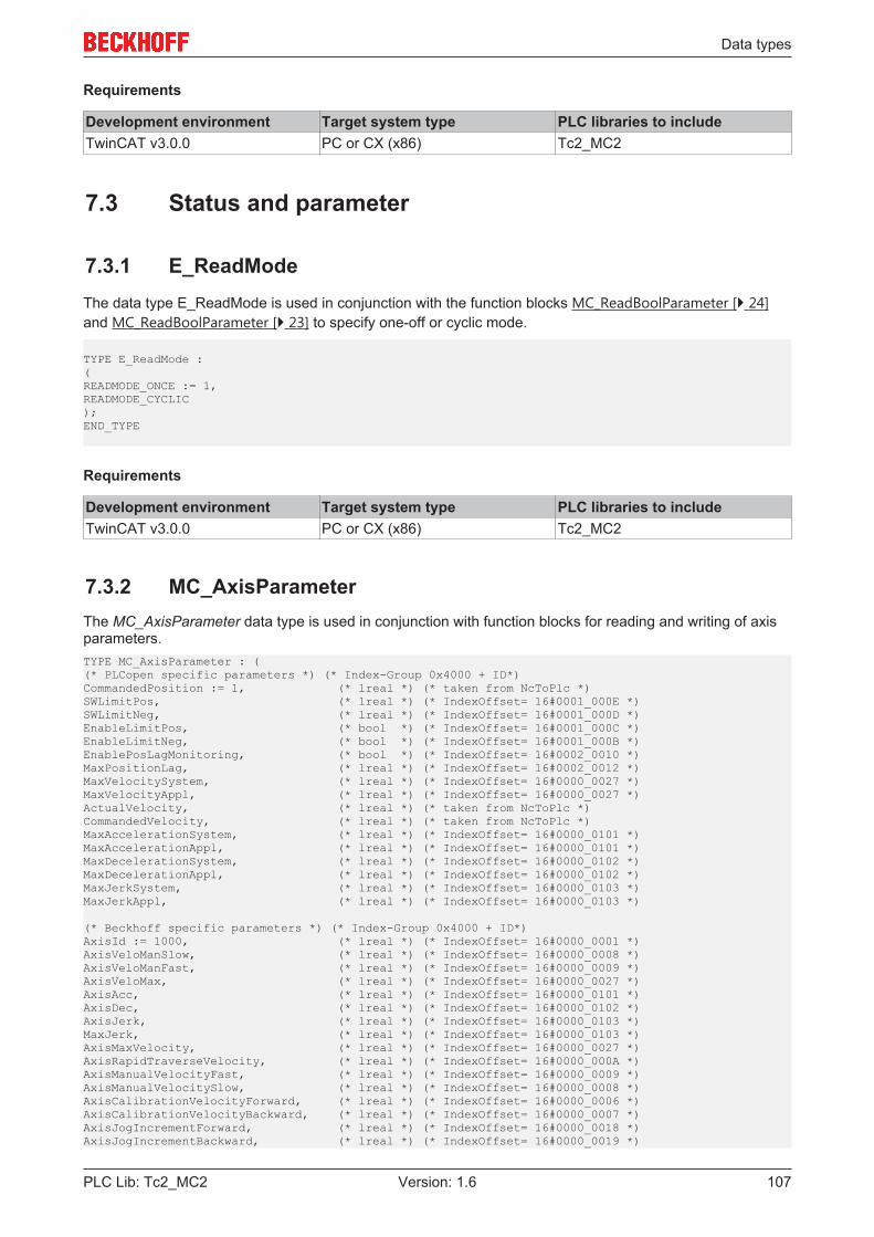
Data types
PLC Lib: Tc2_MC2 107Version: 1.6
Requirements
Development environment Target system type PLC libraries to includeTwinCAT v3.0.0 PC or CX (x86) Tc2_MC2
7.3 Status and parameter
7.3.1 E_ReadModeThe data type E_ReadMode is used in conjunction with the function blocks MC_ReadBoolParameter [} 24]and MC_ReadBoolParameter [} 23] to specify one-off or cyclic mode.
TYPE E_ReadMode :(READMODE_ONCE := 1,READMODE_CYCLIC);END_TYPE
Requirements
Development environment Target system type PLC libraries to includeTwinCAT v3.0.0 PC or CX (x86) Tc2_MC2
7.3.2 MC_AxisParameterThe MC_AxisParameter data type is used in conjunction with function blocks for reading and writing of axisparameters.TYPE MC_AxisParameter : ((* PLCopen specific parameters *) (* Index-Group 0x4000 + ID*)CommandedPosition := 1, (* lreal *) (* taken from NcToPlc *)SWLimitPos, (* lreal *) (* IndexOffset= 16#0001_000E *)SWLimitNeg, (* lreal *) (* IndexOffset= 16#0001_000D *)EnableLimitPos, (* bool *) (* IndexOffset= 16#0001_000C *)EnableLimitNeg, (* bool *) (* IndexOffset= 16#0001_000B *)EnablePosLagMonitoring, (* bool *) (* IndexOffset= 16#0002_0010 *)MaxPositionLag, (* lreal *) (* IndexOffset= 16#0002_0012 *)MaxVelocitySystem, (* lreal *) (* IndexOffset= 16#0000_0027 *)MaxVelocityAppl, (* lreal *) (* IndexOffset= 16#0000_0027 *)ActualVelocity, (* lreal *) (* taken from NcToPlc *)CommandedVelocity, (* lreal *) (* taken from NcToPlc *)MaxAccelerationSystem, (* lreal *) (* IndexOffset= 16#0000_0101 *)MaxAccelerationAppl, (* lreal *) (* IndexOffset= 16#0000_0101 *)MaxDecelerationSystem, (* lreal *) (* IndexOffset= 16#0000_0102 *)MaxDecelerationAppl, (* lreal *) (* IndexOffset= 16#0000_0102 *)MaxJerkSystem, (* lreal *) (* IndexOffset= 16#0000_0103 *)MaxJerkAppl, (* lreal *) (* IndexOffset= 16#0000_0103 *)
(* Beckhoff specific parameters *) (* Index-Group 0x4000 + ID*)AxisId := 1000, (* lreal *) (* IndexOffset= 16#0000_0001 *)AxisVeloManSlow, (* lreal *) (* IndexOffset= 16#0000_0008 *)AxisVeloManFast, (* lreal *) (* IndexOffset= 16#0000_0009 *)AxisVeloMax, (* lreal *) (* IndexOffset= 16#0000_0027 *)AxisAcc, (* lreal *) (* IndexOffset= 16#0000_0101 *)AxisDec, (* lreal *) (* IndexOffset= 16#0000_0102 *)AxisJerk, (* lreal *) (* IndexOffset= 16#0000_0103 *)MaxJerk, (* lreal *) (* IndexOffset= 16#0000_0103 *)AxisMaxVelocity, (* lreal *) (* IndexOffset= 16#0000_0027 *)AxisRapidTraverseVelocity, (* lreal *) (* IndexOffset= 16#0000_000A *)AxisManualVelocityFast, (* lreal *) (* IndexOffset= 16#0000_0009 *)AxisManualVelocitySlow, (* lreal *) (* IndexOffset= 16#0000_0008 *)AxisCalibrationVelocityForward, (* lreal *) (* IndexOffset= 16#0000_0006 *)AxisCalibrationVelocityBackward, (* lreal *) (* IndexOffset= 16#0000_0007 *)AxisJogIncrementForward, (* lreal *) (* IndexOffset= 16#0000_0018 *)AxisJogIncrementBackward, (* lreal *) (* IndexOffset= 16#0000_0019 *)
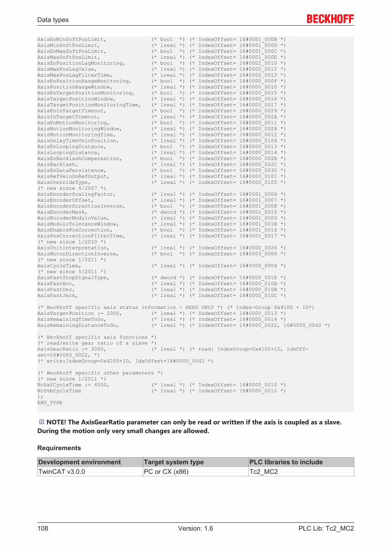
Data types
PLC Lib: Tc2_MC2108 Version: 1.6
AxisEnMinSoftPosLimit, (* bool *) (* IndexOffset= 16#0001_000B *)AxisMinSoftPosLimit, (* lreal *) (* IndexOffset= 16#0001_000D *)AxisEnMaxSoftPosLimit, (* bool *) (* IndexOffset= 16#0001_000C *)AxisMaxSoftPosLimit, (* lreal *) (* IndexOffset= 16#0001_000E *)AxisEnPositionLagMonitoring, (* bool *) (* IndexOffset= 16#0002_0010 *)AxisMaxPosLagValue, (* lreal *) (* IndexOffset= 16#0002_0012 *)AxisMaxPosLagFilterTime, (* lreal *) (* IndexOffset= 16#0002_0013 *)AxisEnPositionRangeMonitoring, (* bool *) (* IndexOffset= 16#0000_000F *)AxisPositionRangeWindow, (* lreal *) (* IndexOffset= 16#0000_0010 *)AxisEnTargetPositionMonitoring, (* bool *) (* IndexOffset= 16#0000_0015 *)AxisTargetPositionWindow, (* lreal *) (* IndexOffset= 16#0000_0016 *)AxisTargetPositionMonitoringTime, (* lreal *) (* IndexOffset= 16#0000_0017 *)AxisEnInTargetTimeout, (* bool *) (* IndexOffset= 16#0000_0029 *)AxisInTargetTimeout, (* lreal *) (* IndexOffset= 16#0000_002A *)AxisEnMotionMonitoring, (* bool *) (* IndexOffset= 16#0000_0011 *)AxisMotionMonitoringWindow, (* lreal *) (* IndexOffset= 16#0000_0028 *)AxisMotionMonitoringTime, (* lreal *) (* IndexOffset= 16#0000_0012 *)AxisDelayTimeVeloPosition, (* lreal *) (* IndexOffset= 16#0000_0104 *)AxisEnLoopingDistance, (* bool *) (* IndexOffset= 16#0000_0013 *)AxisLoopingDistance, (* lreal *) (* IndexOffset= 16#0000_0014 *)AxisEnBacklashCompensation, (* bool *) (* IndexOffset= 16#0000_002B *)AxisBacklash, (* lreal *) (* IndexOffset= 16#0000_002C *)AxisEnDataPersistence, (* bool *) (* IndexOffset= 16#0000_0030 *)AxisRefVeloOnRefOutput, (* lreal *) (* IndexOffset= 16#0003_0101 *)AxisOverrideType, (* lreal *) (* IndexOffset= 16#0000_0105 *)(* new since 4/2007 *)AxisEncoderScalingFactor, (* lreal *) (* IndexOffset= 16#0001_0006 *)AxisEncoderOffset, (* lreal *) (* IndexOffset= 16#0001_0007 *)AxisEncoderDirectionInverse, (* bool *) (* IndexOffset= 16#0001_0008 *)AxisEncoderMask, (* dword *) (* IndexOffset= 16#0001_0015 *)AxisEncoderModuloValue, (* lreal *) (* IndexOffset= 16#0001_0009 *)AxisModuloToleranceWindow, (* lreal *) (* IndexOffset= 16#0001_001B *)AxisEnablePosCorrection, (* bool *) (* IndexOffset= 16#0001_0016 *)AxisPosCorrectionFilterTime, (* lreal *) (* IndexOffset= 16#0001_0017 *)(* new since 1/2010 *)AxisUnitInterpretation, (* lreal *) (* IndexOffset= 16#0000_0026 *)AxisMotorDirectionInverse, (* bool *) (* IndexOffset= 16#0003_0006 *)(* new since 1/2011 *)AxisCycleTime, (* lreal *) (* IndexOffset= 16#0000_0004 *)(* new since 5/2011 *)AxisFastStopSignalType, (* dword *) (* IndexOffset= 16#0000_001E *)AxisFastAcc, (* lreal *) (* IndexOffset= 16#0000_010A *)AxisFastDec, (* lreal *) (* IndexOffset= 16#0000_010B *)AxisFastJerk, (* lreal *) (* IndexOffset= 16#0000_010C *)
(* Beckhoff specific axis status information - READ ONLY *) (* Index-Group 0x4100 + ID*)AxisTargetPosition := 2000, (* lreal *) (* IndexOffset= 16#0000_0013 *)AxisRemainingTimeToGo, (* lreal *) (* IndexOffset= 16#0000_0014 *)AxisRemainingDistanceToGo, (* lreal *) (* IndexOffset= 16#0000_0022, 16#0000_0042 *)
(* Beckhoff specific axis functions *)(* read/write gear ratio of a slave *)AxisGearRatio := 3000, (* lreal *) (* read: IndexGroup=0x4100+ID, IdxOff-set=16#0000_0022, *)(* write:IndexGroup=0x4200+ID, IdxOffset=16#0000_0042 *)
(* Beckhoff specific other parameters *)(* new since 1/2011 *)NcSafCycleTime := 4000, (* lreal *) (* IndexOffset= 16#0000_0010 *)NcSvbCycleTime (* lreal *) (* IndexOffset= 16#0000_0012 *));END_TYPE
NOTE! The AxisGearRatio parameter can only be read or written if the axis is coupled as a slave.During the motion only very small changes are allowed.
Requirements
Development environment Target system type PLC libraries to includeTwinCAT v3.0.0 PC or CX (x86) Tc2_MC2
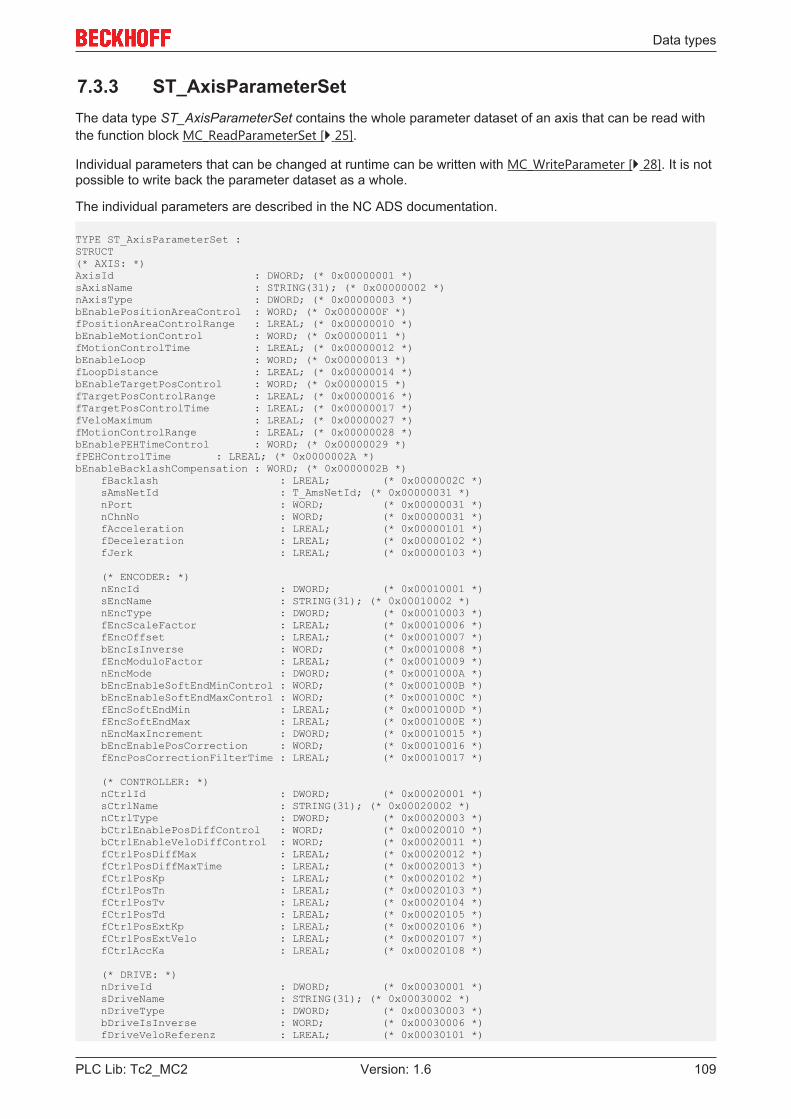
Data types
PLC Lib: Tc2_MC2 109Version: 1.6
7.3.3 ST_AxisParameterSetThe data type ST_AxisParameterSet contains the whole parameter dataset of an axis that can be read withthe function block MC_ReadParameterSet [} 25].
Individual parameters that can be changed at runtime can be written with MC_WriteParameter [} 28]. It is notpossible to write back the parameter dataset as a whole.
The individual parameters are described in the NC ADS documentation.
TYPE ST_AxisParameterSet :STRUCT(* AXIS: *)AxisId : DWORD; (* 0x00000001 *)sAxisName : STRING(31); (* 0x00000002 *)nAxisType : DWORD; (* 0x00000003 *)bEnablePositionAreaControl : WORD; (* 0x0000000F *)fPositionAreaControlRange : LREAL; (* 0x00000010 *)bEnableMotionControl : WORD; (* 0x00000011 *)fMotionControlTime : LREAL; (* 0x00000012 *)bEnableLoop : WORD; (* 0x00000013 *)fLoopDistance : LREAL; (* 0x00000014 *)bEnableTargetPosControl : WORD; (* 0x00000015 *)fTargetPosControlRange : LREAL; (* 0x00000016 *)fTargetPosControlTime : LREAL; (* 0x00000017 *)fVeloMaximum : LREAL; (* 0x00000027 *)fMotionControlRange : LREAL; (* 0x00000028 *)bEnablePEHTimeControl : WORD; (* 0x00000029 *)fPEHControlTime : LREAL; (* 0x0000002A *)bEnableBacklashCompensation : WORD; (* 0x0000002B *) fBacklash : LREAL; (* 0x0000002C *) sAmsNetId : T_AmsNetId; (* 0x00000031 *) nPort : WORD; (* 0x00000031 *) nChnNo : WORD; (* 0x00000031 *) fAcceleration : LREAL; (* 0x00000101 *) fDeceleration : LREAL; (* 0x00000102 *) fJerk : LREAL; (* 0x00000103 *)
(* ENCODER: *) nEncId : DWORD; (* 0x00010001 *) sEncName : STRING(31); (* 0x00010002 *) nEncType : DWORD; (* 0x00010003 *) fEncScaleFactor : LREAL; (* 0x00010006 *) fEncOffset : LREAL; (* 0x00010007 *) bEncIsInverse : WORD; (* 0x00010008 *) fEncModuloFactor : LREAL; (* 0x00010009 *) nEncMode : DWORD; (* 0x0001000A *) bEncEnableSoftEndMinControl : WORD; (* 0x0001000B *) bEncEnableSoftEndMaxControl : WORD; (* 0x0001000C *) fEncSoftEndMin : LREAL; (* 0x0001000D *) fEncSoftEndMax : LREAL; (* 0x0001000E *) nEncMaxIncrement : DWORD; (* 0x00010015 *) bEncEnablePosCorrection : WORD; (* 0x00010016 *) fEncPosCorrectionFilterTime : LREAL; (* 0x00010017 *)
(* CONTROLLER: *) nCtrlId : DWORD; (* 0x00020001 *) sCtrlName : STRING(31); (* 0x00020002 *) nCtrlType : DWORD; (* 0x00020003 *) bCtrlEnablePosDiffControl : WORD; (* 0x00020010 *) bCtrlEnableVeloDiffControl : WORD; (* 0x00020011 *) fCtrlPosDiffMax : LREAL; (* 0x00020012 *) fCtrlPosDiffMaxTime : LREAL; (* 0x00020013 *) fCtrlPosKp : LREAL; (* 0x00020102 *) fCtrlPosTn : LREAL; (* 0x00020103 *) fCtrlPosTv : LREAL; (* 0x00020104 *) fCtrlPosTd : LREAL; (* 0x00020105 *) fCtrlPosExtKp : LREAL; (* 0x00020106 *) fCtrlPosExtVelo : LREAL; (* 0x00020107 *) fCtrlAccKa : LREAL; (* 0x00020108 *)
(* DRIVE: *) nDriveId : DWORD; (* 0x00030001 *) sDriveName : STRING(31); (* 0x00030002 *) nDriveType : DWORD; (* 0x00030003 *) bDriveIsInverse : WORD; (* 0x00030006 *) fDriveVeloReferenz : LREAL; (* 0x00030101 *)
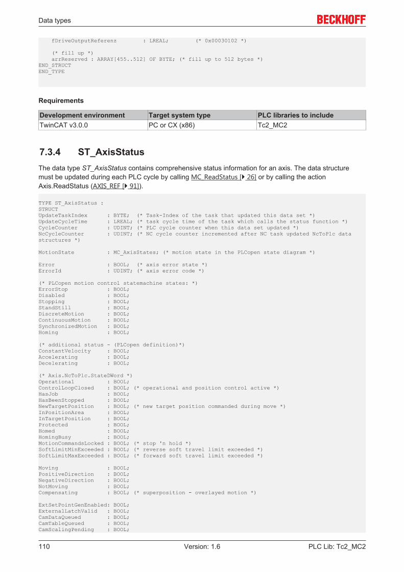
Data types
PLC Lib: Tc2_MC2110 Version: 1.6
fDriveOutputReferenz : LREAL; (* 0x00030102 *)
(* fill up *) arrReserved : ARRAY[455..512] OF BYTE; (* fill up to 512 bytes *)END_STRUCTEND_TYPE
Requirements
Development environment Target system type PLC libraries to includeTwinCAT v3.0.0 PC or CX (x86) Tc2_MC2
7.3.4 ST_AxisStatusThe data type ST_AxisStatus contains comprehensive status information for an axis. The data structuremust be updated during each PLC cycle by calling MC_ReadStatus [} 26] or by calling the actionAxis.ReadStatus (AXIS_REF [} 91]).
TYPE ST_AxisStatus :STRUCTUpdateTaskIndex : BYTE; (* Task-Index of the task that updated this data set *)UpdateCycleTime : LREAL; (* task cycle time of the task which calls the status function *)CycleCounter : UDINT; (* PLC cycle counter when this data set updated *)NcCycleCounter : UDINT; (* NC cycle counter incremented after NC task updated NcToPlc datastructures *)
MotionState : MC_AxisStates; (* motion state in the PLCopen state diagram *)
Error : BOOL; (* axis error state *)ErrorId : UDINT; (* axis error code *)
(* PLCopen motion control statemachine states: *)ErrorStop : BOOL;Disabled : BOOL;Stopping : BOOL;StandStill : BOOL;DiscreteMotion : BOOL;ContinuousMotion : BOOL; SynchronizedMotion : BOOL;Homing : BOOL;
(* additional status - (PLCopen definition)*)ConstantVelocity : BOOL; Accelerating : BOOL;Decelerating : BOOL;
(* Axis.NcToPlc.StateDWord *)Operational : BOOL; ControlLoopClosed : BOOL; (* operational and position control active *)HasJob : BOOL; HasBeenStopped : BOOL; NewTargetPosition : BOOL; (* new target position commanded during move *)InPositionArea : BOOL; InTargetPosition : BOOL; Protected : BOOL; Homed : BOOL; HomingBusy : BOOL; MotionCommandsLocked : BOOL; (* stop 'n hold *)SoftLimitMinExceeded : BOOL; (* reverse soft travel limit exceeded *)SoftLimitMaxExceeded : BOOL; (* forward soft travel limit exceeded *)
Moving : BOOL; PositiveDirection : BOOL; NegativeDirection : BOOL; NotMoving : BOOL; Compensating : BOOL; (* superposition - overlayed motion *)
ExtSetPointGenEnabled: BOOL; ExternalLatchValid : BOOL; CamDataQueued : BOOL; CamTableQueued : BOOL; CamScalingPending : BOOL;

Data types
PLC Lib: Tc2_MC2 111Version: 1.6
CmdBuffered : BOOL; PTPmode : BOOL; DriveDeviceError : BOOL; IoDataInvalid : BOOL;
(* Axis.NcToPlc.CoupleState *)Coupled : BOOL;
(* axis operation mode feedback from NcToPlc *)OpMode : ST_AxisOpModes;END_STRUCTEND_TYPE
Requirements
Development environment Target system type PLC libraries to includeTwinCAT v3.0.0 PC or CX (x86) Tc2_MC2
7.3.5 ST_DriveAddressThe data type ST_DriveAddress contains the ADS access data for a drive unit. The data are read withMC_ReadDriveAddress [} 47]
TYPE ST_DriveAddress :STRUCTNetID : T_AmsNetId; (* AMS NetID of the drive as a string *)NetIdBytes : T_AmsNetIdArr; (* AMS NetID of the drive as a byte array (same information as NetID)*)SlaveAddress : T_AmsPort; (* slave address of the drive connected to a bus master *)Channel : BYTE; (* channel number of the drive *)(* new since 2013-04-04 - just available with versions after this date, otherwise zero *)NcDriveId :DWORD; (* ID [1..255] of the NC software drive of an axis *)NcDriveIndex : DWORD; (* index [0..9] of the NC software drive of an axis *)NcDriveType : DWORD; (* type enumeration of the NC software drive of an axis *)NcEncoderId : DWORD; (* ID [1..255] of the NC software encoder of an axis *)NcEncoderIndex : DWORD; (* index [0..9] of the NC software encoder of an axis *)NcEncoderType : DWORD; (* type enumeration of the NC encoder drive of an axis *)NcAxisId : DWORD; (* ID [1..255] of the NC axis *)NcAxisType : DWORD; (* type enumeration of the NC axis *)END_STRUCTEND_TYPE
Requirements
Development environment Target system type PLC libraries to includeTwinCAT v3.0.0 PC or CX (x86) Tc2_MC2
7.3.6 ST_PowerStepperStruct
TYPE ST_PowerStepperStruct :STRUCTDestallDetectMode : E_DestallDetectMode;DestallMode : E_DestallMode;DestallEnable : BOOL;StatusMonEnable : BOOL;Retries : INT;Timeout : TIME;END_STRUCTEND_TYPE
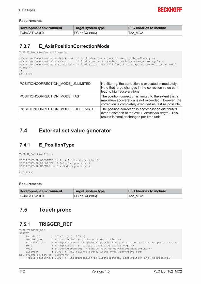
Data types
PLC Lib: Tc2_MC2112 Version: 1.6
Requirements
Development environment Target system type PLC libraries to includeTwinCAT v3.0.0 PC or CX (x86) Tc2_MC2
7.3.7 E_AxisPositionCorrectionModeTYPE E_PositionCorrectionMode:(POSITIONCORRECTION_MODE_UNLIMITED, (* no limitation - pass correction immediately *)POSITIONCORRECTION_MODE_FAST, (* limitatation to maximum position change per cycle *)POSITIONCORRECTION_MODE_FULLLENGTH (* limitation uses full length to adapt to correction in smallsteps *));END_TYPE
POSITIONCORRECTION_MODE_UNLIMITED No filtering, the correction is executed immediately.Note that large changes in the correction value canlead to high accelerations.
POSITIONCORRECTION_MODE_FAST The position correction is limited to the extent that amaximum acceleration is not exceeded. However, thecorrection is completely executed as fast as possible.
POSITIONCORRECTION_MODE_FULLLENGTH The position correction is accomplished distributedover a distance of the axis (CorrectionLength). Thisresults in smaller changes per time unit.
7.4 External set value generator
7.4.1 E_PositionType
TYPE E_PositionType :(POSITIONTYPE_ABSOLUTE := 1, (*Absolute position*)POSITIONTYPE_RELATIVE, (*Relative position*)POSITIONTYPE_MODULO := 5 (*Modulo position*));END_TYPE
Requirements
Development environment Target system type PLC libraries to includeTwinCAT v3.0.0 PC or CX (x86) Tc2_MC2
7.5 Touch probe
7.5.1 TRIGGER_REFTYPE TRIGGER_REF :STRUCT EncoderID : UDINT; (* 1..255 *) TouchProbe : E_TouchProbe; (* probe unit definition *) SignalSource : E_SignalSource; (* optional physical signal source used by the probe unit *) Edge : E_SignalEdge; (* rising or falling signal edge *) Mode : E_TouchProbeMode; (* single shot or continuous monitoring *) PlcEvent : BOOL; (* PLC trigger signal input when TouchProbe sig-nal source is set to 'PlcEvent' *) ModuloPositions : BOOL; (* interpretation of FirstPosition, LastPosition and RecordedPosi-
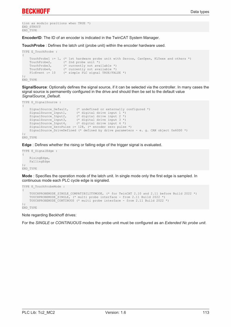
Data types
PLC Lib: Tc2_MC2 113Version: 1.6
tion as modulo positions when TRUE *)END_STRUCTEND_TYPE
EncoderID: The ID of an encoder is indicated in the TwinCAT System Manager.
TouchProbe : Defines the latch unit (probe unit) within the encoder hardware used.TYPE E_TouchProbe :( TouchProbe1 := 1, (* 1st hardware probe unit with Sercos, CanOpen, KL5xxx and others *) TouchProbe2, (* 2nd probe unit *) TouchProbe3, (* currently not available *) TouchProbe4, (* currently not available *) PlcEvent := 10 (* simple PLC signal TRUE/FALSE *));END_TYPE
SignalSource: Optionally defines the signal source, if it can be selected via the controller. In many cases thesignal source is permanently configured in the drive and should then be set to the default valueSignalSource_Default.TYPE E_SignalSource :( SignalSource_Default, (* undefined or externally configured *) SignalSource_Input1, (* digital drive input 1 *) SignalSource_Input2, (* digital drive input 2 *) SignalSource_Input3, (* digital drive input 3 *) SignalSource_Input4, (* digital drive input 4 *) SignalSource_ZeroPulse := 128, (* encoder zero pulse *) SignalSource_DriveDefined (* defined by drive parameters - e. g. CAN object 0x60D0 *));END_TYPE
Edge : Defines whether the rising or falling edge of the trigger signal is evaluated.TYPE E_SignalEdge :( RisingEdge, FallingEdge);END_TYPE
Mode : Specifies the operation mode of the latch unit. In single mode only the first edge is sampled. Incontinuous mode each PLC cycle edge is signaled.TYPE E_TouchProbeMode :( TOUCHPROBEMODE_SINGLE_COMPATIBILITYMODE, (* for TwinCAT 2.10 and 2.11 before Build 2022 *) TOUCHPROBEMODE_SINGLE, (* multi probe interface - from 2.11 Build 2022 *) TOUCHPROBEMODE_CONTINOUS (* multi probe interface - from 2.11 Build 2022 *));END_TYPE
Note regarding Beckhoff drives:
For the SINGLE or CONTINUOUS modes the probe unit must be configured as an Extended Nc probe unit.
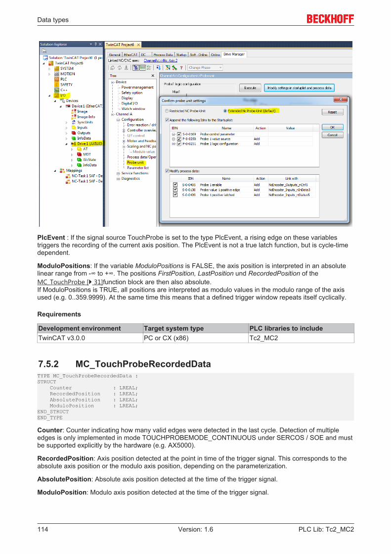
Data types
PLC Lib: Tc2_MC2114 Version: 1.6
PlcEvent : If the signal source TouchProbe is set to the type PlcEvent, a rising edge on these variablestriggers the recording of the current axis position. The PlcEvent is not a true latch function, but is cycle-timedependent.
ModuloPositions: If the variable ModuloPositions is FALSE, the axis position is interpreted in an absolutelinear range from -∞ to +∞. The positions FirstPosition, LastPosition und RecordedPosition of theMC_TouchProbe [} 31]function block are then also absolute.If ModuloPositions is TRUE, all positions are interpreted as modulo values in the modulo range of the axisused (e.g. 0..359.9999). At the same time this means that a defined trigger window repeats itself cyclically.
Requirements
Development environment Target system type PLC libraries to includeTwinCAT v3.0.0 PC or CX (x86) Tc2_MC2
7.5.2 MC_TouchProbeRecordedDataTYPE MC_TouchProbeRecordedData :STRUCT Counter : LREAL; RecordedPosition : LREAL; AbsolutePosition : LREAL; ModuloPosition : LREAL;END_STRUCTEND_TYPE
Counter: Counter indicating how many valid edges were detected in the last cycle. Detection of multipleedges is only implemented in mode TOUCHPROBEMODE_CONTINUOUS under SERCOS / SOE and mustbe supported explicitly by the hardware (e.g. AX5000).
RecordedPosition: Axis position detected at the point in time of the trigger signal. This corresponds to theabsolute axis position or the modulo axis position, depending on the parameterization.
AbsolutePosition: Absolute axis position detected at the time of the trigger signal.
ModuloPosition: Modulo axis position detected at the time of the trigger signal.
Global constants
PLC Lib: Tc2_MC2 115Version: 1.6
8 Global constants
8.1 Library versionAll libraries have a certain version. The version is indicated in the PLC library repository, for example. Aglobal constant contains the information about the library version:
Global_VersionVAR_GLOBAL CONSTANT stLibVersion_Tc2_MC2 : ST_LibVersion;END_VAR
stLibVersion_Tc2_MC2: version information of the Tc2_MC2 library (Typ: ST_LibVersion).
To check whether the version you have is the version you need, use the function F_CmpLibVersion (definedin Tc2_System library).
NOTE! All other options for comparing library versions, which you may know from TwinCAT 2, areoutdated!
Samples
PLC Lib: Tc2_MC2116 Version: 1.6
9 Samples
9.1 Summary of examplesThe sample programs use the Tc2_MC2 library and run entirely in simulation mode.
Progress can be monitored in TwinCAT Scope View with the configuration provided.
PTP – point to point movement
The example program manages and moves an axis in PTP mode. The axis is moved with two instances ofan MC_MoveAbsolute function block in queued mode over several intermediate positions and velocity levels.
https://infosys.beckhoff.com/content/1033/TcPlcLib_Tc2_MC2/Resources/zip/9007201641738507.zip
Master-Slave coupling
The example program couples two axes and moves them together. The slave axis is uncoupled andpositioned during the journey.
https://infosys.beckhoff.com/content/1033/TcPlcLib_Tc2_MC2/Resources/zip/9007201641736843.zip
Dancer control
The dancer control sample program shows how the velocity of a slave axis can be controlled using theposition of a dancer.
https://infosys.beckhoff.com/content/1033/TcPlcLib_Tc2_MC2/Resources/zip/9007201641733515.zip
Superimposed movement (Superposition)
The example shows the overlay of a movement while an axis is driving.
https://infosys.beckhoff.com/content/1033/TcPlcLib_Tc2_MC2/Resources/zip/9007201641740171.zip
Compensation of the backlash of an axis
The sample program shows how the backlash of an axis can be compensated
https://infosys.beckhoff.com/content/1033/TcPlcLib_Tc2_MC2/Resources/zip/9007201641730187.zip
External setpoint generation
The example shows how an axis can be moved via the external setpoint generator. The movement of the NCaxis “Axis” is generated as the sum of the individual movements of the other two Nc axes.
https://infosys.beckhoff.com/content/1033/TcPlcLib_Tc2_MC2/Resources/zip/9007201641735179.zip
Control loop switching in an AX5000 with two existing encoders
The sample illustrates switching between two axis control loops
Suitable hardware is required for this sample.
https://infosys.beckhoff.com/content/1033/TcPlcLib_Tc2_MC2/Resources/zip/9007201641731851.zip
Requirements
Development environment Target system type PLC libraries to includeTwinCAT v3.0.0 PC or CX (x86) Tc2_MC2
Related Documents