MS53 Laboratory Mixer Iss 6.doc OPERATING, INSTALLATION & MAINTENANCE MANUAL FOR MS-53 LABORATORY MIXER This JISKOOT Product is designed to provide outstanding service if correctly installed, used and maintained recognising the effects of the process conditions (temperature, pressure, wax/pour point, sediment, etc.). Truly representative sampling of crude oils etc., cannot be achieved by one single product in isolation. A well designed system and operating procedures as laid down in the Sampling Standards ISO 3171, API 8.2 and IP Chapter VI section 2 are mandatory. Please consult Sensia for further information and assistance. No part of this document may be reproduced or transmitted in any form or by any means, electronic or mechanical, for any purpose, without the express written permission of Sensia.

Welcome message from author
This document is posted to help you gain knowledge. Please leave a comment to let me know what you think about it! Share it to your friends and learn new things together.
Transcript
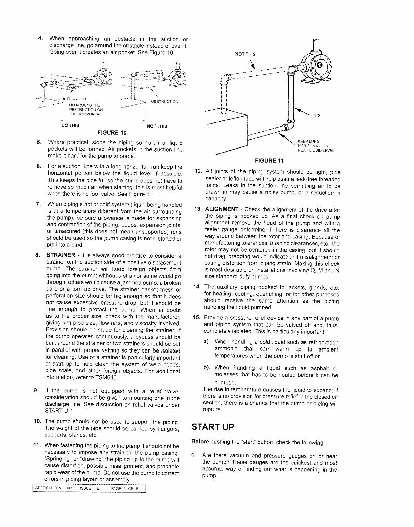
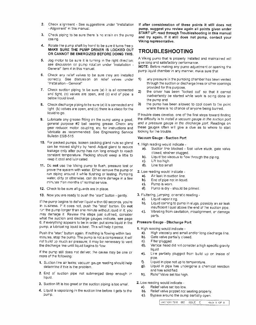
MS53 Laboratory Mixer Iss 6.doc
OPERATING, INSTALLATION & MAINTENANCE MANUAL
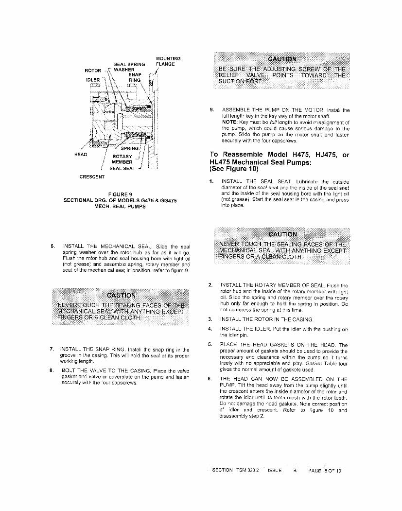
FOR
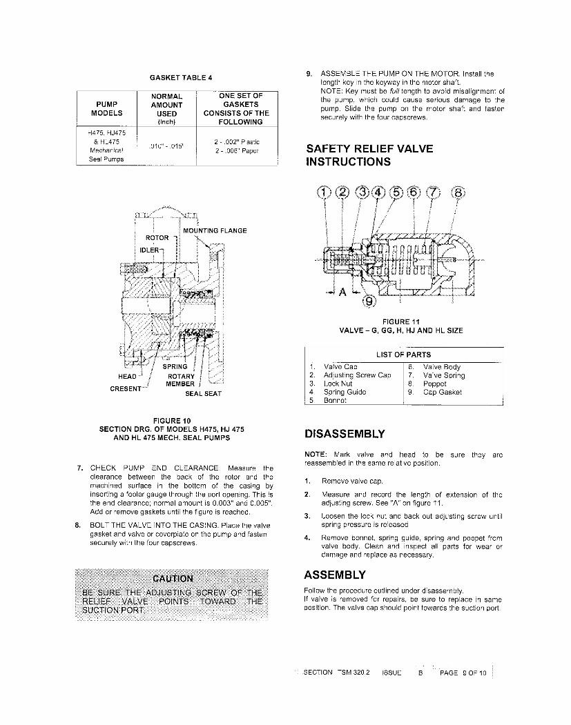
MS-53 LABORATORY MIXER
This JISKOOT Product is designed to provide outstanding service if correctly installed, usedand maintained recognising the effects of the process conditions (temperature, pressure, wax/pour point, sediment, etc.).
Truly representative sampling of crude oils etc., cannot be achieved by one single product in isolation. A well designed system and operating procedures as laid down in the Sampling Standards ISO 3171, API 8.2 and IP Chapter VI section 2 are mandatory.
Please consult Sensia for further information and assistance.
No part of this document may be reproduced or transmitted in any form or by any means, electronic or mechanical, for any purpose, without the express written permission of Sensia.

MS-53 Laboratory Mixer
Issue No 6
TABLE OF CONTENTS
1 WARRANTY ....................................................................................................... 4
2 INTRODUCTION ................................................................................................. 4
3 OPERATING INSTRUCTIONS ........................................................................... 5
4 FULL FUNCTIONAL DESCRIPTION ................................................................. 5
5 UTILITIES REFERENCE .................................................................................... 5
6 INSTALLATION DETAILS ................................................................................. 6
7 MAINTENANCE & TROUBLESHOOTING ......................................................... 6
8 SUB SUPPLIER INFORMATION ....................................................................... 6
9 PRODUCT SPECIFIC DRAWINGS .................................................................... 7
10 RECOMMENDED SPARES LIST ................................................................... 7
11 DISCLAIMER .................................................................................................. 8
MS-53 Laboratory Mixer
Issue No 6 Page 4
1 Warranty
This product should be supplied with a warranty card. Please complete and return it to register for warranty support.
In the event it is missing, to register for support, please contact us on +44 (0)1892 518000 or [email protected], quoting the Jiskoot Order Number or Serial No with the following information:
Date installed
Full installation site details, including contact details
Maintenance and operator contact details (where different from above)
Product comments/feedback
If the product has been supplied as part of a Jiskoot system or assembly, please complete the warranty card for the system.
2 Introduction
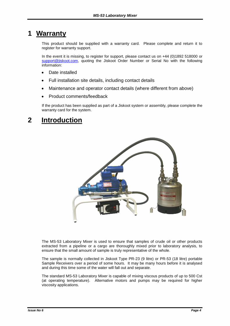
The MS-53 Laboratory Mixer is used to ensure that samples of crude oil or other products extracted from a pipeline or a cargo are thoroughly mixed prior to laboratory analysis, to ensure that the small amount of sample is truly representative of the whole.
The sample is normally collected in Jiskoot Type PR-23 (9 litre) or PR-53 (18 litre) portable Sample Receivers over a period of some hours. It may be many hours before it is analysed and during this time some of the water will fall out and separate.
The standard MS-53 Laboratory Mixer is capable of mixing viscous products of up to 500 Cst (at operating temperature). Alternative motors and pumps may be required for higher viscosity applications.
MS-53 Laboratory Mixer
Issue No 6 Page 5
3 Operating Instructions
The MS-53 Laboratory Mixer is simple to operate.
The Mixer must be firmly located on a suitable bench and connected to a suitable electrical supply.
The 3/4" suction and 1/2" discharge hoses must be connected to the appropriate connections of the Sample Receiver. Ensure that the quick release couplings are connected properly by pulling gently on the hoses.
Apply power to the Mixer. Mixing time is a function of gravity, viscosity and various other factors. Tests have shown that the Laboratory Mixer will successfully mix a variety of oils within 5-10 minutes, however, the optimum mixing time will vary depending on the composition of the oil.
When crude oil is sampled at a high temperature, allowed to cool and then reheated, condensation may form in the Sample Receiver. If this occurs, ensure the can is briefly shaken by hand to remove water droplets from the top of the receiver.
In some instances the pump may need assistance in priming. To do this lift the receiver up with the mixer running until the pump primes.
NOTE: To avoid damage to the pump, the Laboratory Mixer should not be operated for periods exceeding 3 minutes if no product available.
When the oil is thoroughly mixed, draw off a sample from the needle valve into laboratory glassware for analysis. Alternatively, a septum may be fitted to the Mixer to enable the sample to be taken using a syringe. It is recommended that the initial 10-20ml of sample be discarded, to ensure all equipment is thoroughly flushed.
When sufficient sample has been obtained, switch off the mixer and thoroughly clean all equipment to prevent cross contamination.
4 Full Functional Description
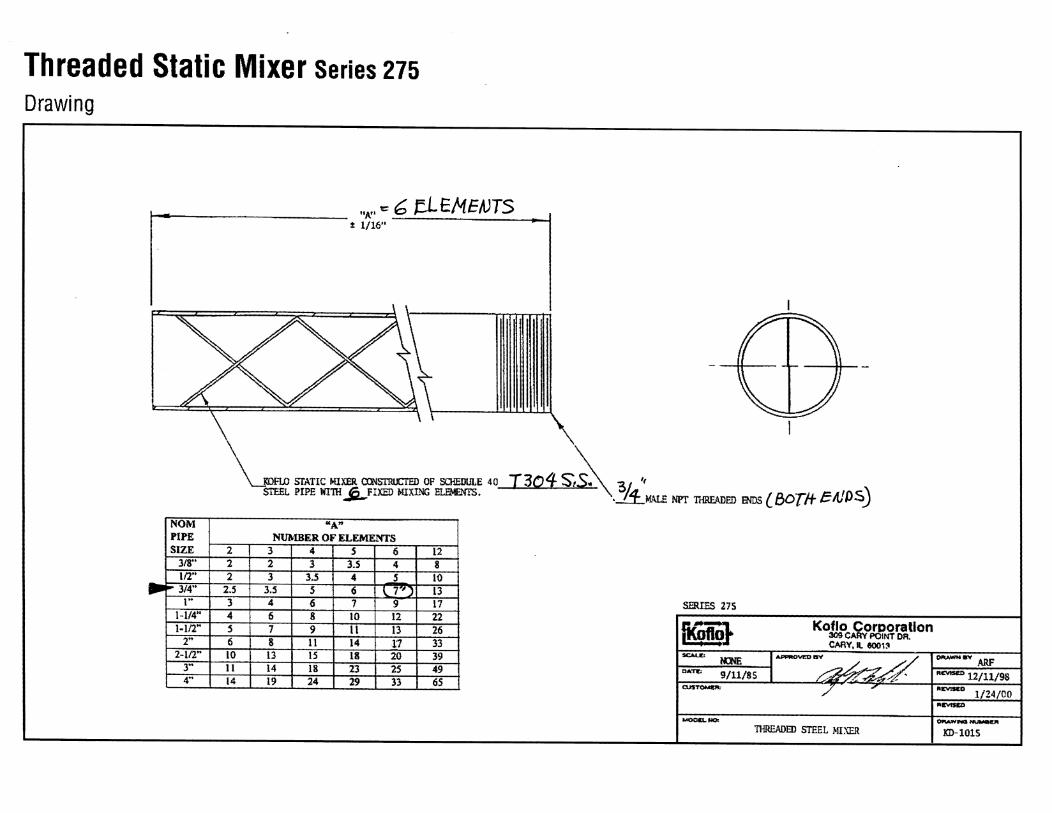
The MS-53 Laboratory Mixer consists of a loop drawing oil from the lowest point in the Sample Receiver through the electric motor driven gear pump. The oil is discharged from the pump through the static mixer and returned to the receiver. The return pipe of the Sample Receiver is pointed down, tangentially towards the wall of the receiver to promote extra mixing.
The Laboratory Mixer is fitted with a needle valve to enable the sample to be drawn off into laboratory glassware. In addition, a septum may be fitted to enable a sample to be drawn off via a syringe.
The MS-53 Laboratory Mixer is normally supplied with an electric motor, but is also available with a pneumatic motor for applications where electricity is not an available power source.
5 Utilities Reference
Electrical Requirements 100/110 or 240/220 Volts, 50 or 60 Hz to suit motor supplied.
Power Requirement 0.5KW
Pneumatic Option 3Barg/45psig lubricated air supply.
MS-53 Laboratory Mixer
Issue No 6 Page 6
6 Installation Details
The Laboratory Mixer must be installed and operated in compliance with any applicable electrical hazardous area regulations. The electrical supply should be connected to the motor isolating switch via a suitably certified M20 cable gland, ensuring that earth continuity across the switch is maintained.
7 Maintenance & Troubleshooting
Other than cleaning after use, the MS-53 Laboratory Mixer requires minimal maintenance.
The septum rubbers are self-sealing, however if a leakage is noted, they must be replaced with new rubbers.
Both Laboratory Mixer and Sample Receiver must be cleaned to prevent cross-contamination of samples.
The recommended method for cleaning this equipment is to use a solvent and an inert gas (e.g. Nitrogen) as follows:-
1) Remove Sample Receiver from Laboratory Mixer and empty.2) Re-connect Sample Receiver and run Laboratory Mixer for approximately 15
seconds.3) Disconnect and empty Sample Receiver.4) Add 2 litres of solvent (Toluene or Kerosene).5) Turn on Laboratory Mixer and circulate for one minute.6) Turn off and remove pump suction hose (3/4" connector)7) Connect suction to inert gas source (Nitrogen) NOT compressed air.8) Carefully blow out Laboratory Mixer with inert gas. NOTE: The gas pressure will
relieve through the Sample Receiver relief valve.9) Remove Sample Receiver. Clean with solvent and leave inverted with cover
removed to drain.
DO NOT UNDER ANY CIRCUMSTANCES:-
1) Use compressed air for purging.2) Run the Laboratory Mixer with the discharge hose disconnected or shut off - high
pressures will build up and may cause the hose to rupture.
3) Run the Laboratory Mixer unprimed or with solvent for long periods
8 Sub Supplier Information
8.1 Electric motor
The electric motor requires no routine maintenance. In the event of a fault, the motor should be replaced or fully overhauled by a qualified repair shop.
8.2 Gear Pump Overhaul
The gear pump has minimal serviceable components. A replacement seal kit is available for site replacement if required, but as any wear on the gears and body faces causes loss of performance, a replacement pump is recommended.
8.3 Pneumatic Motor
Before dismantling the pump, using a broad felt tip marker pen, draw a line on the pump outer casing from the foot/flange casting across the centre body casting to the end cover casting.
1) Slacken and remove the 4 socket head set pins.2) Remove end cover casting.
MS-53 Laboratory Mixer
Issue No 6 Page 7
3) Remove centre body casting.4) Remove gears and shafts.5) Remove dowels.6) Clean components, removing traces of paint, and/or gasket material from body sides.
8.3.1 Examine:
1) Shafts for signs of wear (a maximum reduction of .002” difference from diameter ofunworn part of shaft is acceptable).
2) Gears, tooth form and gear end faces for wear, scuffing or damage, and replace ifnecessary.
3) Lip Seal/s for damage caused by dirt or metal particles, etc. and replace if necessary.
NOTE: With double lip seal arrangements, ensure that the seals are re-fitted facing exactly the same direction as the seals they replaced.
8.3.2 Reassembly
1) Ensure that all components are clean and free from dirt and paint etc.2) Measure the body width and gear width and fit paper gaskets to allow a maximum of
0.002" running clearance.3) Fit dowels.4) Align the components to the felt marker line and re-assemble in reverse order to the
dismantling procedure.5) Tighten the 4 socket head set pins evenly and diagonally whilst rotating the driveshaft
by hand. Ensure that the pump rotates evenly for the full 360o without tightness.
Should tightness occur, slacken set pins and try again.
6) If the pump cannot be assembled as indicated, examine gears for damage and, ifsatisfactory, fit an extra gasket to one face and repeat from 5 above.
9 Product Specific Drawings
9.1.1 Laboratory Mixer Type MS53-E (Electrically Driven)
General Arrangement Drawing B18103
Septum Assembly Drawing E16473
9.1.2 Laboratory Mixer Type MS53-P (Pneumatically Driven)
General Arrangement Drawing B18602
Septum Assembly Drawing E16473
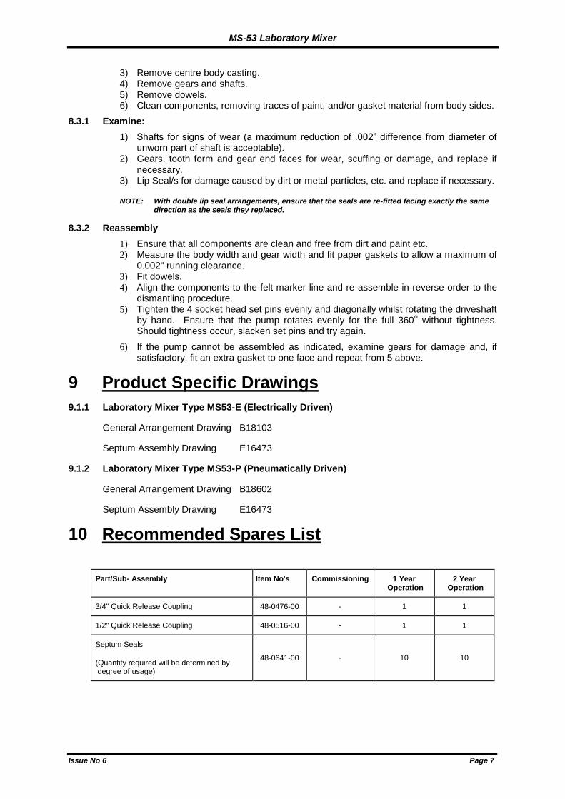
10 Recommended Spares List
Part/Sub- Assembly Item No's Commissioning 1 Year Operation
2 Year Operation
3/4" Quick Release Coupling 48-0476-00 - 1 1
1/2" Quick Release Coupling 48-0516-00 - 1 1
Septum Seals
(Quantity required will be determined by degree of usage)
48-0641-00 - 10 10
MS-53 Laboratory Mixer
Issue No 6 Page 8
11 Disclaimer
Whilst Jiskoot Limited has taken every care in the preparation of this document, it cannot accept responsibility for printing errors or omissions and does not warrant that it is correct and comprehensive in every particular. Persons with an appropriate level of skill and training should operate equipment supplied only.
Jiskoot Limited shall not be liable for incidental or consequential damages resulting from the furnishing, performance or use of this material.
Jiskoot pursues a policy of continuous improvement, and information given herein may be updated without notice. Further, this information is proprietary to Jiskoot Limited, and must not be disclosed to any third party except as may be required to operate the equipment supplied in accordance with the purposes for which it was sold by the persons properly licensed to operate it.
6 Recommended Spares List corrected P.Whittle N.McGee 07/01/2009
5 Company name updated P.Whittle M.A.Jiskoot 02/02/2006
4 Note added regarding maximum product viscosity for standard unit P.Whittle M.A.Jiskoot 27/08/2003
3 Rewritten in MS Word format M.Doust P.Whittle 02/06/2003
2 Drawing and Parts List references updated P.Whittle P.Whittle 25/04/2000
1
Issue Revision History Issued Approved Date

MS-53 Laboratory Mixer
Issue No 6 Page 9
Notes
MS-53 Laboratory Mixer
Issue No 6 Page 10
Notes


www.jiskoot.com
Tunbridge Wells, Kent, TN1 2DJ, UK Tel +44 (0)1892 518000, Fax +44 (0)1892 518100 e-mail: [email protected]
Houston, TX77014, USA Tel +1 281 583 0583, Fax +1 281 583 0587 e-mail: [email protected]
14503 Bammel North Houston Suite 110 Houston Texas 77014 Tel 281 583 0583 Fax 281 583 0587 Email [email protected]
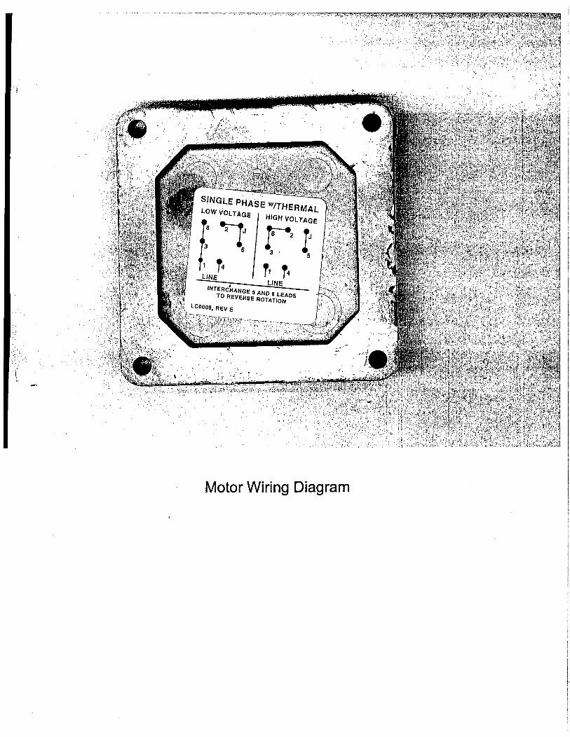
The Jiskoot Lab Mixer MS-53E
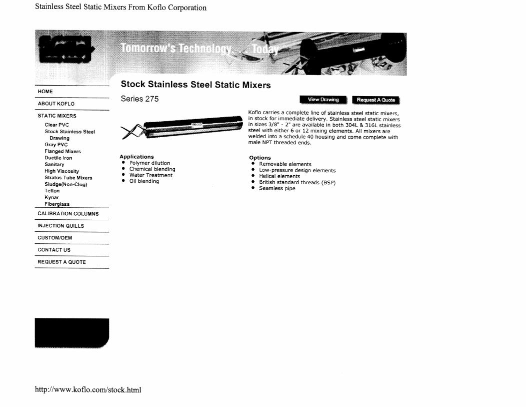
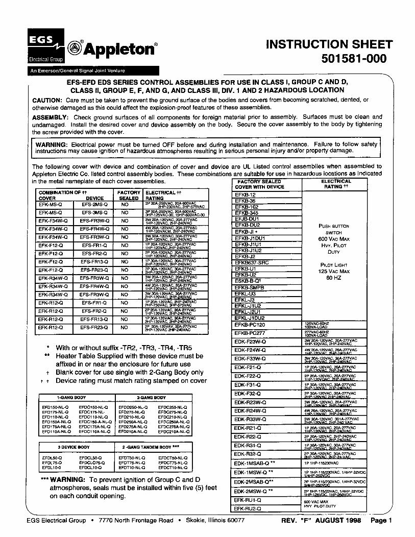
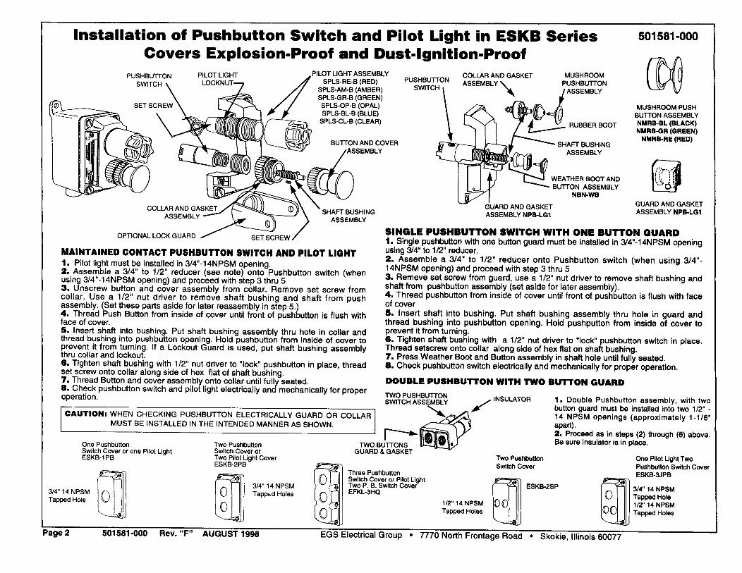
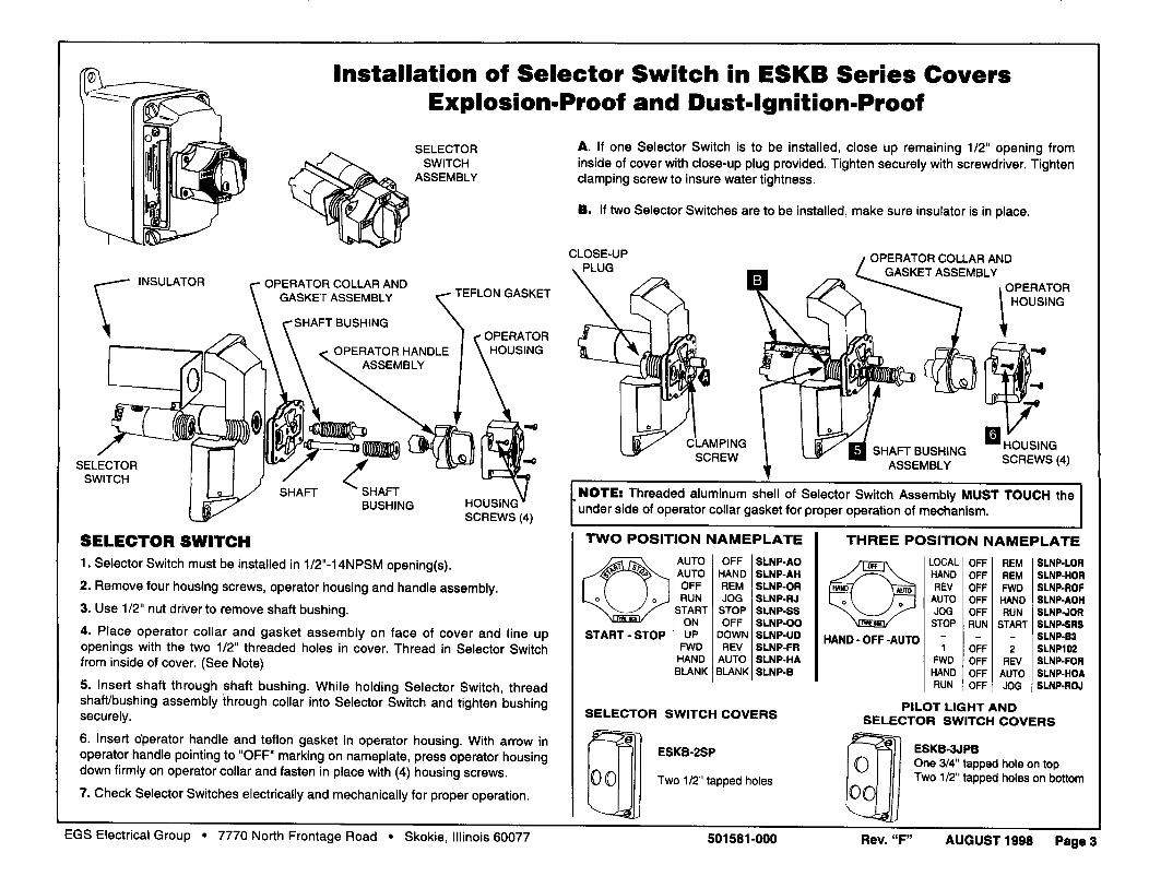
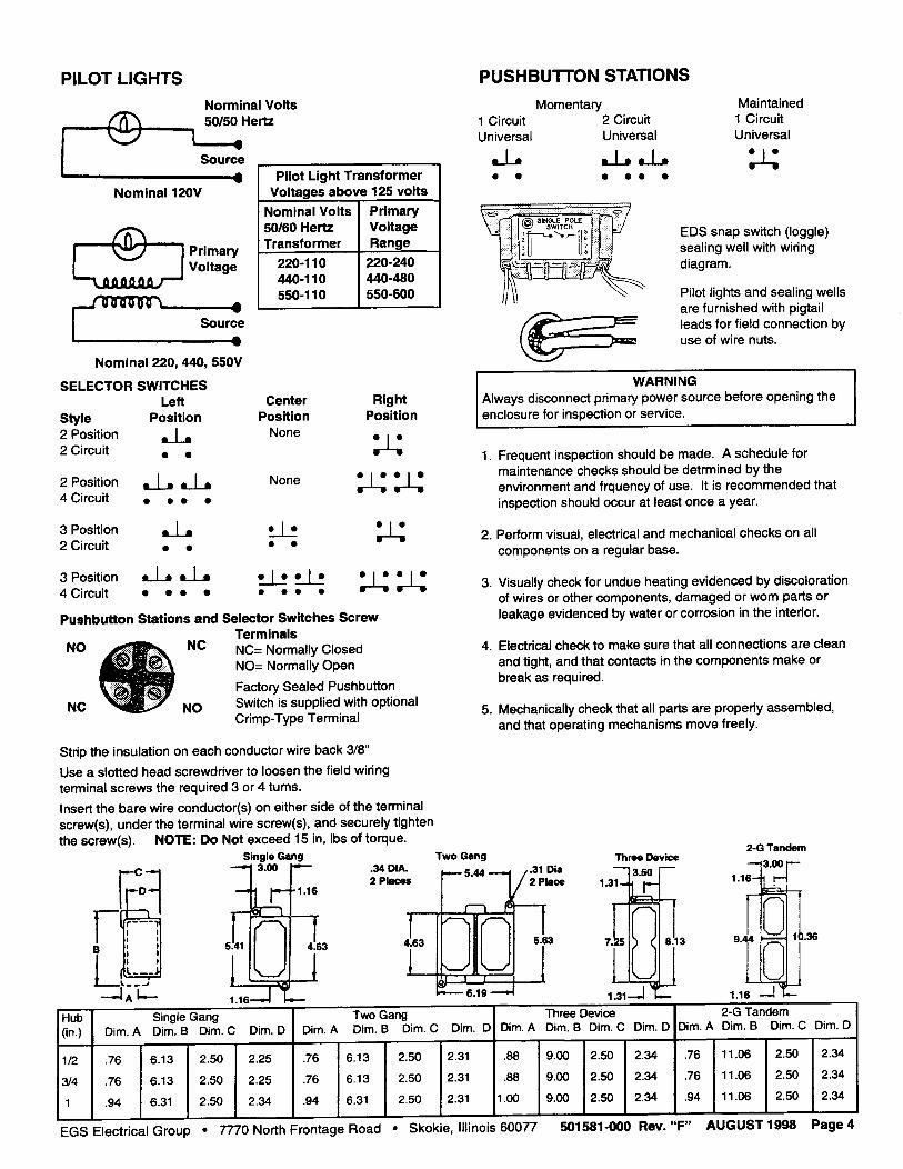
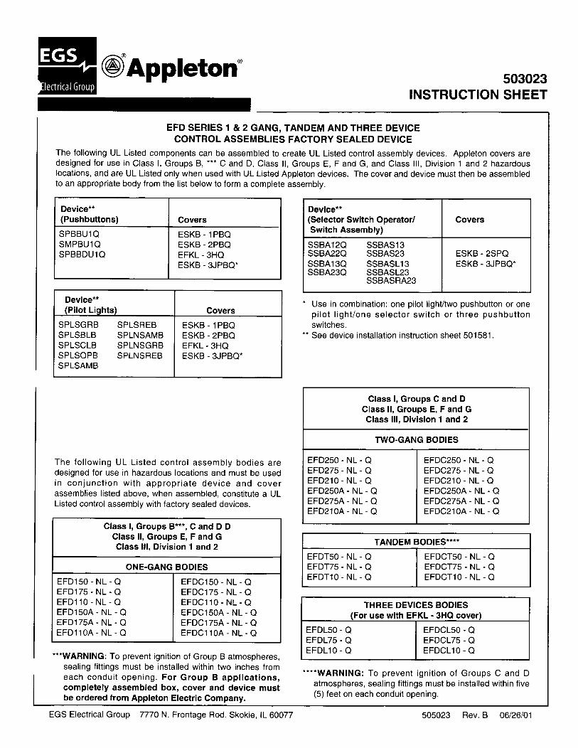
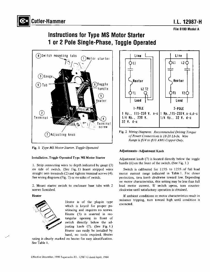
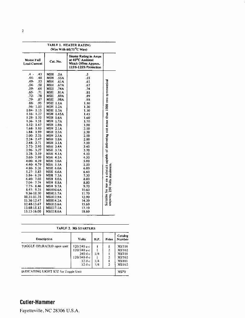
1. Baldor Explosion Proof Motor Installation & Operating Manual 2. Viking Pump Technical Service Manuals 3. Koflo Six Element Static Mixer 4. Appleton Switch Housing 5. Cutter-Hammer Single Phase Switch w/ Plug-in Heater 6. Hazardous Area Electrical Certifications

Integral Horsepower
AC Induction Motors
ODP, WPI, WPII Enclosure
TEFC Enclosure
Explosion Proof
Installation & Operating Manual
5/04 MN400
Table of Contents
Table of Contents iMN400
Section 1General Information 1-1. . . . . . . . . . . . . . . . . . . . . . . . . . . . . . . . . . . . . . . . . . . . . . . . . . . . . . . . . . . . . . . . . . . . . . . . . . . . . .
Overview 1-1. . . . . . . . . . . . . . . . . . . . . . . . . . . . . . . . . . . . . . . . . . . . . . . . . . . . . . . . . . . . . . . . . . . . . . . . . . . . . . . . . . . .
Limited Warranty 1-1. . . . . . . . . . . . . . . . . . . . . . . . . . . . . . . . . . . . . . . . . . . . . . . . . . . . . . . . . . . . . . . . . . . . . . . . . . . . . .
Safety Notice 1-2. . . . . . . . . . . . . . . . . . . . . . . . . . . . . . . . . . . . . . . . . . . . . . . . . . . . . . . . . . . . . . . . . . . . . . . . . . . . . . . . .
Receiving 1-4. . . . . . . . . . . . . . . . . . . . . . . . . . . . . . . . . . . . . . . . . . . . . . . . . . . . . . . . . . . . . . . . . . . . . . . . . . . . . . . . . . . .
Storage 1-4. . . . . . . . . . . . . . . . . . . . . . . . . . . . . . . . . . . . . . . . . . . . . . . . . . . . . . . . . . . . . . . . . . . . . . . . . . . . . . . . . . . . . .
Unpacking 1-4. . . . . . . . . . . . . . . . . . . . . . . . . . . . . . . . . . . . . . . . . . . . . . . . . . . . . . . . . . . . . . . . . . . . . . . . . . . . . . . . . . .
Handling 1-4. . . . . . . . . . . . . . . . . . . . . . . . . . . . . . . . . . . . . . . . . . . . . . . . . . . . . . . . . . . . . . . . . . . . . . . . . . . . . . . . . . . . .
Section 2Installation & Operation 2-1. . . . . . . . . . . . . . . . . . . . . . . . . . . . . . . . . . . . . . . . . . . . . . . . . . . . . . . . . . . . . . . . . . . . . . . . . . .
Overview 2-1. . . . . . . . . . . . . . . . . . . . . . . . . . . . . . . . . . . . . . . . . . . . . . . . . . . . . . . . . . . . . . . . . . . . . . . . . . . . . . . . . . . .
Location 2-1. . . . . . . . . . . . . . . . . . . . . . . . . . . . . . . . . . . . . . . . . . . . . . . . . . . . . . . . . . . . . . . . . . . . . . . . . . . . . . . . . . . . .
Mounting 2-1. . . . . . . . . . . . . . . . . . . . . . . . . . . . . . . . . . . . . . . . . . . . . . . . . . . . . . . . . . . . . . . . . . . . . . . . . . . . . . . . . . . . .
Alignment 2-1. . . . . . . . . . . . . . . . . . . . . . . . . . . . . . . . . . . . . . . . . . . . . . . . . . . . . . . . . . . . . . . . . . . . . . . . . . . . . . . . . . . .
Doweling & Bolting 2-2. . . . . . . . . . . . . . . . . . . . . . . . . . . . . . . . . . . . . . . . . . . . . . . . . . . . . . . . . . . . . . . . . . . . . . . . . . . .
Power Connection 2-2. . . . . . . . . . . . . . . . . . . . . . . . . . . . . . . . . . . . . . . . . . . . . . . . . . . . . . . . . . . . . . . . . . . . . . . . . . . . .
Conduit Box 2-2. . . . . . . . . . . . . . . . . . . . . . . . . . . . . . . . . . . . . . . . . . . . . . . . . . . . . . . . . . . . . . . . . . . . . . . . . . . . . .
AC Power 2-2. . . . . . . . . . . . . . . . . . . . . . . . . . . . . . . . . . . . . . . . . . . . . . . . . . . . . . . . . . . . . . . . . . . . . . . . . . . . . . . .
First Time Start Up 2-4. . . . . . . . . . . . . . . . . . . . . . . . . . . . . . . . . . . . . . . . . . . . . . . . . . . . . . . . . . . . . . . . . . . . . . . . . . . .
Coupled Start Up 2-4. . . . . . . . . . . . . . . . . . . . . . . . . . . . . . . . . . . . . . . . . . . . . . . . . . . . . . . . . . . . . . . . . . . . . . . . . . . . . .
Jogging and Repeated Starts 2-4. . . . . . . . . . . . . . . . . . . . . . . . . . . . . . . . . . . . . . . . . . . . . . . . . . . . . . . . . . . . . . . . . . .
Section 3Maintenance & Troubleshooting 3-1. . . . . . . . . . . . . . . . . . . . . . . . . . . . . . . . . . . . . . . . . . . . . . . . . . . . . . . . . . . . . . . . . . .
General Inspection 3-1. . . . . . . . . . . . . . . . . . . . . . . . . . . . . . . . . . . . . . . . . . . . . . . . . . . . . . . . . . . . . . . . . . . . . . . . . . . .
Lubrication & Bearings 3-1. . . . . . . . . . . . . . . . . . . . . . . . . . . . . . . . . . . . . . . . . . . . . . . . . . . . . . . . . . . . . . . . . . . . . . . . .
Type of Grease 3-1. . . . . . . . . . . . . . . . . . . . . . . . . . . . . . . . . . . . . . . . . . . . . . . . . . . . . . . . . . . . . . . . . . . . . . . . . . .
Lubrication Intervals 3-1. . . . . . . . . . . . . . . . . . . . . . . . . . . . . . . . . . . . . . . . . . . . . . . . . . . . . . . . . . . . . . . . . . . . . . .
Lubrication Procedure 3-3. . . . . . . . . . . . . . . . . . . . . . . . . . . . . . . . . . . . . . . . . . . . . . . . . . . . . . . . . . . . . . . . . . . . .
Accessories 3-4. . . . . . . . . . . . . . . . . . . . . . . . . . . . . . . . . . . . . . . . . . . . . . . . . . . . . . . . . . . . . . . . . . . . . . . . . . . . . . . . . .
Troubleshooting Chart 3-5. . . . . . . . . . . . . . . . . . . . . . . . . . . . . . . . . . . . . . . . . . . . . . . . . . . . . . . . . . . . . . . . . . . . . . . . .

Section 1General Information
ii Table of Contents MN400
Section 1General Information
General Information 1-1MN400
Overview This manual contains general procedures that apply to Baldor Motor products. Be sure to read andunderstand the Safety Notice statements in this manual. For your protection, do not install, operate orattempt to perform maintenance procedures until you understand the Warning and Caution statements. AWarning statement indicates a possible unsafe condition that can cause harm to personnel. A Cautionstatement indicates a condition that can cause damage to equipment.
Important: This instruction manual is not intended to include a comprehensive listing of all details for allprocedures required for installation, operation and maintenance. This manual describes generalguidelines that apply to most of the motor products shipped by Baldor. If you have a questionabout a procedure or are uncertain about any detail, Do Not Proceed. Please contact your Baldordistributor for more information or clarification.
Before you install, operate or perform maintenance, become familiar with the following:� NEMA Publication MG-2, Safety Standard for Construction and guide
for Selection, Installation and Use of Electric Motors and Generators.� The National Electrical Code� Local codes and Practices
Limited Warranty
1. Most Baldor products are warranted for 18 months from the date of shipment to Baldor�s customer from Baldor�sdistrict warehouse or, if applicable, from Baldor�s factory. Baldor Standard�E® standard efficient motors arewarranted for 24 months. Standard�E is limited to three phase, general purpose, 1�200 HP ratings that fall underthe Energy Policy Act (EPAct). Baldor Super�E® premium efficient motors are warranted for 36 months. BaldorIEEE841 motors are warranted for 60 months. All warranty claims must be submitted to a Baldor Service Centerprior to the expiration of the warranty period.
2. Baldor will, at its option repair or replace a motor which fails due to defects in material or workmanship during thewarranty period if:
a. the purchaser presents the defective motor at or ships it prepaid to, the Baldor plant in Fort Smith, Arkansasor one of the Baldor Authorized Service Centers and
b. the purchaser gives written notification concerning the motor and the claimed defect including the datepurchased, the task performed by the Baldor motor and the problem encountered.
3. Baldor will not pay the cost of removal of any electric motor from any equipment, the cost of delivery to Fort Smith,Arkansas or a Baldor Authorized Service Center, or the cost of any incidental or consequential damages resultingfrom the claimed defects. (Some states do not allow the exclusion or limitation of incidental or consequentialdamages, so the above exclusion may not apply to you.) Any implied warranty given by laws shall be limited tothe duration of the warranty period hereunder. (Some states do not allow limitations on how long an impliedwarranty lasts, so the above limitation may not apply to you.)
4. Baldor Authorized Service Centers, when convinced to their satisfaction that a Baldor motor developed defects inmaterial or workmanship within the warranty period, are authorized to proceed with the required repairs to fulfillBaldor�s warranty when the cost of such repairs to be paid by Baldor does not exceed Baldor�s warranty repairallowance. Baldor will not pay overtime premium repair charges without prior written authorization.
5. The cost of warranty repairs made by centers other than Baldor Authorized Service Centers WILL NOT be paidunless first authorized in writing by Baldor.
6. Claims by a purchaser that a motor is defective even when a failure results within one hour after being placed intoservice are not always justified. Therefore, Baldor Authorized Service Centers must determine from the conditionof the motor as delivered to the center whether or not the motor is defective. If in the opinion of a BaldorAuthorized Service Center, a motor did not fail as a result of defects in material or workmanship, the center is toproceed with repairs only if the purchaser agrees to pay for such repairs. If the decision is in dispute, thepurchaser should still pay for the repairs and submit the paid invoice and the Authorized Service Center�s signedservice report to Baldor for further consideration.
7. This warranty gives you specific legal rights, and you may also have other rights which vary from state to state.
1-2 General Information MN400
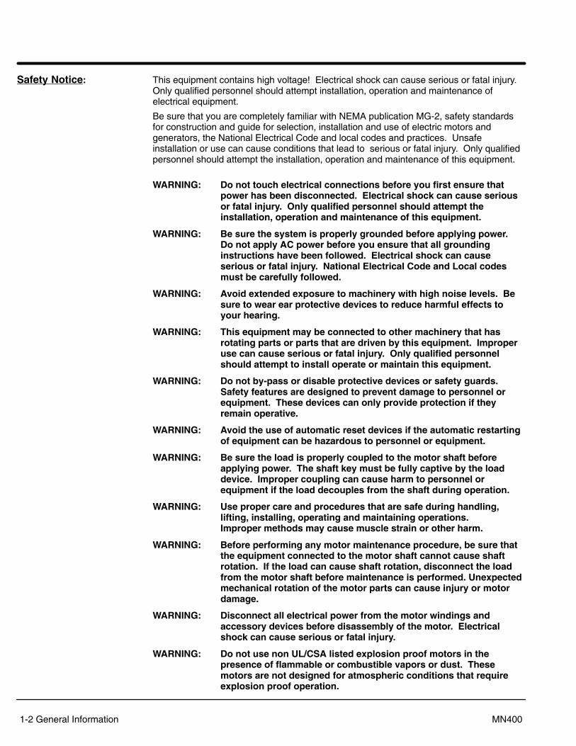
Safety Notice: This equipment contains high voltage! Electrical shock can cause serious or fatal injury.Only qualified personnel should attempt installation, operation and maintenance ofelectrical equipment.
Be sure that you are completely familiar with NEMA publication MG-2, safety standardsfor construction and guide for selection, installation and use of electric motors andgenerators, the National Electrical Code and local codes and practices. Unsafeinstallation or use can cause conditions that lead to serious or fatal injury. Only qualifiedpersonnel should attempt the installation, operation and maintenance of this equipment.
WARNING: Do not touch electrical connections before you first ensure thatpower has been disconnected. Electrical shock can cause seriousor fatal injury. Only qualified personnel should attempt theinstallation, operation and maintenance of this equipment.
WARNING: Be sure the system is properly grounded before applying power.Do not apply AC power before you ensure that all groundinginstructions have been followed. Electrical shock can causeserious or fatal injury. National Electrical Code and Local codesmust be carefully followed.
WARNING: Avoid extended exposure to machinery with high noise levels. Besure to wear ear protective devices to reduce harmful effects toyour hearing.
WARNING: This equipment may be connected to other machinery that hasrotating parts or parts that are driven by this equipment. Improperuse can cause serious or fatal injury. Only qualified personnelshould attempt to install operate or maintain this equipment.
WARNING: Do not by-pass or disable protective devices or safety guards.Safety features are designed to prevent damage to personnel orequipment. These devices can only provide protection if theyremain operative.
WARNING: Avoid the use of automatic reset devices if the automatic restartingof equipment can be hazardous to personnel or equipment.
WARNING: Be sure the load is properly coupled to the motor shaft beforeapplying power. The shaft key must be fully captive by the loaddevice. Improper coupling can cause harm to personnel orequipment if the load decouples from the shaft during operation.
WARNING: Use proper care and procedures that are safe during handling,lifting, installing, operating and maintaining operations. Improper methods may cause muscle strain or other harm.
WARNING: Before performing any motor maintenance procedure, be sure thatthe equipment connected to the motor shaft cannot cause shaftrotation. If the load can cause shaft rotation, disconnect the loadfrom the motor shaft before maintenance is performed. Unexpectedmechanical rotation of the motor parts can cause injury or motordamage.
WARNING: Disconnect all electrical power from the motor windings andaccessory devices before disassembly of the motor. Electricalshock can cause serious or fatal injury.
WARNING: Do not use non UL/CSA listed explosion proof motors in thepresence of flammable or combustible vapors or dust. Thesemotors are not designed for atmospheric conditions that requireexplosion proof operation.
Section 1General Information
General Information 1-3MN400
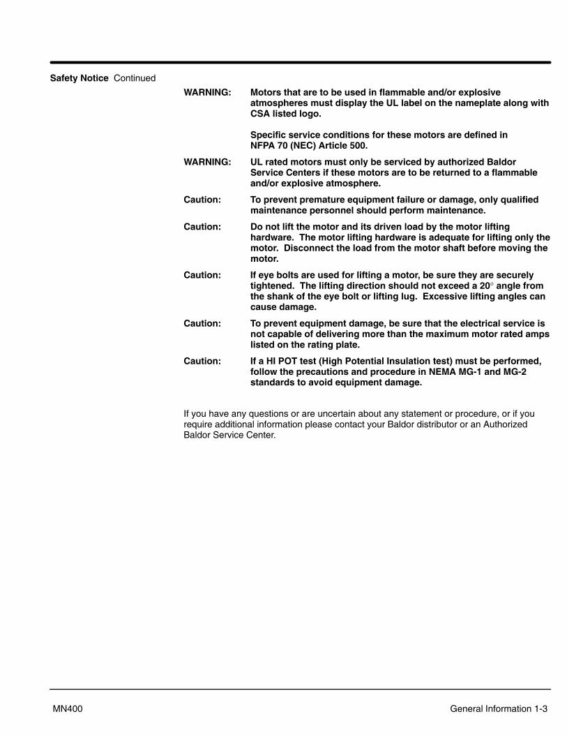
Safety Notice Continued
WARNING: Motors that are to be used in flammable and/or explosiveatmospheres must display the UL label on the nameplate along withCSA listed logo.
Specific service conditions for these motors are defined in NFPA 70 (NEC) Article 500.
WARNING: UL rated motors must only be serviced by authorized BaldorService Centers if these motors are to be returned to a flammableand/or explosive atmosphere.
Caution: To prevent premature equipment failure or damage, only qualifiedmaintenance personnel should perform maintenance.
Caution: Do not lift the motor and its driven load by the motor liftinghardware. The motor lifting hardware is adequate for lifting only themotor. Disconnect the load from the motor shaft before moving themotor.
Caution: If eye bolts are used for lifting a motor, be sure they are securelytightened. The lifting direction should not exceed a 20° angle fromthe shank of the eye bolt or lifting lug. Excessive lifting angles cancause damage.
Caution: To prevent equipment damage, be sure that the electrical service isnot capable of delivering more than the maximum motor rated ampslisted on the rating plate.
Caution: If a HI POT test (High Potential Insulation test) must be performed,follow the precautions and procedure in NEMA MG-1 and MG-2standards to avoid equipment damage.
If you have any questions or are uncertain about any statement or procedure, or if yourequire additional information please contact your Baldor distributor or an AuthorizedBaldor Service Center.
Section 1General Information
1-4 General Information MN400
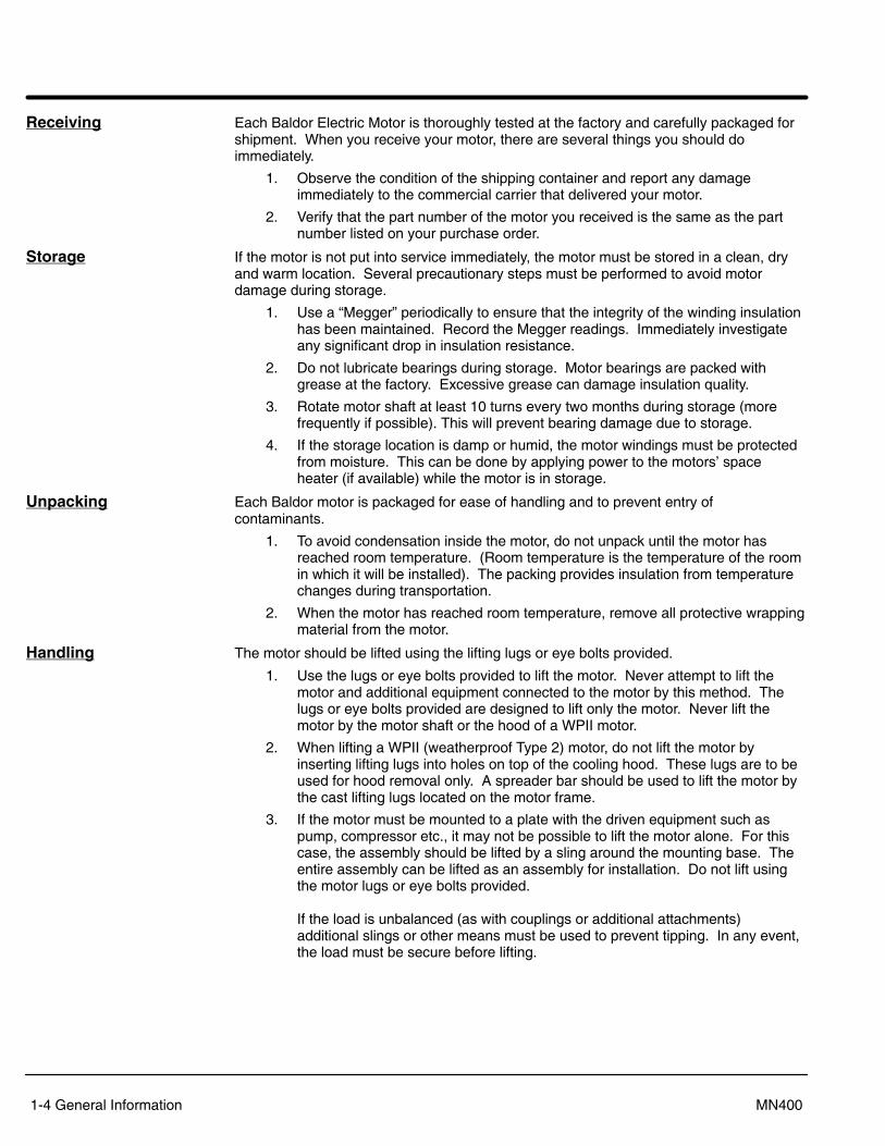
Receiving Each Baldor Electric Motor is thoroughly tested at the factory and carefully packaged forshipment. When you receive your motor, there are several things you should doimmediately.
1. Observe the condition of the shipping container and report any damageimmediately to the commercial carrier that delivered your motor.
2. Verify that the part number of the motor you received is the same as the partnumber listed on your purchase order.
Storage If the motor is not put into service immediately, the motor must be stored in a clean, dryand warm location. Several precautionary steps must be performed to avoid motordamage during storage.
1. Use a �Megger� periodically to ensure that the integrity of the winding insulationhas been maintained. Record the Megger readings. Immediately investigateany significant drop in insulation resistance.
2. Do not lubricate bearings during storage. Motor bearings are packed withgrease at the factory. Excessive grease can damage insulation quality.
3. Rotate motor shaft at least 10 turns every two months during storage (morefrequently if possible). This will prevent bearing damage due to storage.
4. If the storage location is damp or humid, the motor windings must be protectedfrom moisture. This can be done by applying power to the motors� spaceheater (if available) while the motor is in storage.
Unpacking Each Baldor motor is packaged for ease of handling and to prevent entry ofcontaminants.
1. To avoid condensation inside the motor, do not unpack until the motor hasreached room temperature. (Room temperature is the temperature of the roomin which it will be installed). The packing provides insulation from temperaturechanges during transportation.
2. When the motor has reached room temperature, remove all protective wrappingmaterial from the motor.
Handling The motor should be lifted using the lifting lugs or eye bolts provided.
1. Use the lugs or eye bolts provided to lift the motor. Never attempt to lift themotor and additional equipment connected to the motor by this method. Thelugs or eye bolts provided are designed to lift only the motor. Never lift themotor by the motor shaft or the hood of a WPII motor.
2. When lifting a WPII (weatherproof Type 2) motor, do not lift the motor byinserting lifting lugs into holes on top of the cooling hood. These lugs are to beused for hood removal only. A spreader bar should be used to lift the motor bythe cast lifting lugs located on the motor frame.
3. If the motor must be mounted to a plate with the driven equipment such aspump, compressor etc., it may not be possible to lift the motor alone. For thiscase, the assembly should be lifted by a sling around the mounting base. Theentire assembly can be lifted as an assembly for installation. Do not lift usingthe motor lugs or eye bolts provided.
If the load is unbalanced (as with couplings or additional attachments)additional slings or other means must be used to prevent tipping. In any event,the load must be secure before lifting.
Section 2Installation & Operation
Installation & Operation 2-1MN400
Overview Installation should conform to the National Electrical Code as well as local codes andpractices. When other devices are coupled to the motor shaft, be sure to installprotective devices to prevent future accidents. Some protective devices include,coupling, belt guard, chain guard, shaft covers etc. These protect against accidentalcontact with moving parts. Machinery that is accessible to personnel should providefurther protection in the form of guard rails, screening, warning signs etc.
Location It is important that motors be installed in locations that are compatible with motorenclosure and ambient conditions. Improper selection of the motor enclosure andambient conditions can lead to reduced operating life of the motor.
Proper ventilation for the motor must be provided. Obstructed airflow can lead toreduction of motor life.
1. Open Drip�proof/WPI motors are intended for use indoors where atmosphere isrelatively clean, dry, well ventilated and non�corrosive.
2. Totally Enclosed and WPII motors may be installed where dirt, moisture or dust arepresent and in outdoor locations.
Chemical Duty enclosed motors are designed for installations with high corrosion orexcessive moisture conditions. These motors should not be placed into an environmentwhere there is the presence of flammable or combustible vapors, dust or any combustiblematerial, unless specifically designed for this type of service.
Mounting The motor must be securely installed to a rigid foundation or mounting surface tominimize vibration and maintain alignment between the motor and shaft load. Failure toprovide a proper mounting surface may cause vibration, misalignment and bearingdamage.
Foundation caps and sole plates are designed to act as spacers for the equipment theysupport. If these devices are used, be sure that they are evenly supported by thefoundation or mounting surface.
After installation is complete and accurate alignment of the motor and load isaccomplished, the base should be grouted to the foundation to maintain this alignment.
The standard motor base is designed for horizontal or vertical mounting. Adjustable orsliding rails are designed for horizontal mounting only. Consult your Baldor distributor orauthorized Baldor Service Center for further information.
Alignment Accurate alignment of the motor with the driven equipment is extremely important.
1. Direct CouplingFor direct drive, use flexible couplings if possible. Consult the drive or equipmentmanufacturer for more information. Mechanical vibration and roughness duringoperation may indicate poor alignment. Use dial indicators to check alignment. Thespace between coupling hubs should be maintained as recommended by thecoupling manufacturer.
2. End-Play AdjustmentThe axial position of the motor frame with respect to its load is also extremelyimportant. The motor bearings are not designed for excessive external axial thrustloads. Improper adjustment will cause failure.
3. Pulley RatioThe pulley ratio should not exceed 8:1.
4. Belt DriveAlign sheaves carefully to minimize belt wear and axial bearing loads (see End-PlayAdjustment). Belt tension should be sufficient to prevent belt slippage at ratedspeed and load. However, belt slippage may occur during starting.
Caution: Do not over tension belts.
5. Sleeve bearing motors are only suitable for coupled loads.
Section 1General Information
2-2 Installation & Operation MN400
Doweling & Bolting After proper alignment is verified, dowel pins should be inserted through the motor feetinto the foundation. This will maintain the correct motor position should motor removal berequired. (Baldor motors are designed for doweling.)
1. Drill dowel holes in diagonally opposite motor feet in the locations provided.
2. Drill corresponding holes in the foundation.
3. Ream all holes.
4. Install proper fitting dowels.
5. Mounting bolts must be carefully tightened to prevent changes in alignment. Use aflat washer and lock washer under each nut or bolt head to hold the motor feetsecure. Flanged nuts or bolts may be used as an alternative to washers.
Power Connection Motor and control wiring, overload protection, disconnects, accessories and groundingshould conform to the National Electrical Code and local codes and practices.
Conduit Box For ease of making connections, an oversize conduit box is provided. The box can berotated 360° in 90° increments. Auxiliary conduit boxes are provided on some motors foraccessories such as space heaters, RTD�s etc.
AC Power Connect the motor leads as shown on the connection diagram located on the name plateor inside the cover on the conduit box. Be sure the following guidelines are met:
1. AC power is within ±10% of rated voltage with rated frequency. (See motor nameplate for ratings). OR
2. AC power is within ±5% of rated frequency with rated voltage. OR
3. A combined variation in voltage and frequency of ±10% (sum of absolute values) ofrated values, provided the frequency variation does not exceed ±5% of ratedfrequency.
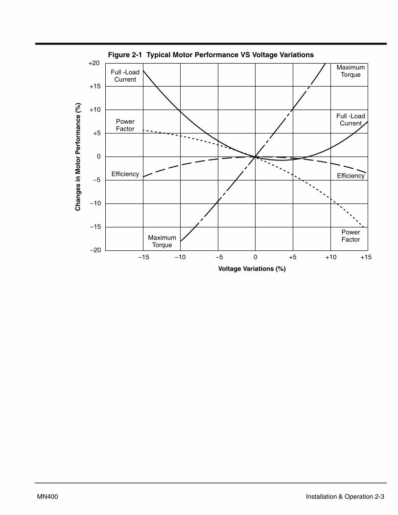
Performance within these voltage and frequency variations are shown in Figure 2-1.
Section 1General Information
Installation & Operation 2-3MN400
Figure 2-1 Typical Motor Performance VS Voltage Variations+20
+15
+10
+5
0
�5
�10
�15
�20�15 �10 �5 0 +5 +10 +15
Voltage Variations (%)
Ch
ang
es in
Mo
tor
Per
form
ance
(%
)Full -LoadCurrent
Full -LoadCurrentPower
Factor
PowerFactor
Efficiency Efficiency
MaximumTorque
MaximumTorque
Section 1General Information
2-4 Installation & Operation MN400
First Time Start Up Be sure that all power to motor and accessories is off. Be sure the motor shaft isdisconnected from the load and will not cause mechanical rotation of the motor shaft.
1. Make sure that the mechanical installation is secure. All bolts and nuts are tightenedetc.
2. If motor has been in storage or idle for some time, check winding insulation integritywith a Megger.
3. Inspect all electrical connections for proper termination, clearance, mechanicalstrength and electrical continuity.
4. Be sure all shipping materials and braces (if used) are removed from motor shaft.
5. Manually rotate the motor shaft to ensure that it rotates freely.
6. Replace all panels and covers that were removed during installation.
7. Momentarily apply power and check the direction of rotation of the motor shaft.
8. If motor rotation is wrong, be sure power is off and change the motor leadconnections. Verify rotation direction before you continue.
9. Start the motor and ensure operation is smooth without excessive vibration or noise.If so, run the motor for 1 hour with no load connected.
10. After 1 hour of operation, disconnect power and connect the load to the motor shaft.Verify all coupling guards and protective devices are installed. Ensure motor isproperly ventilated.
Coupled Start Up This procedure assumes a coupled start up. Also, that the first time start up procedurewas successful.
1. Check the coupling and ensure that all guards and protective devices are installed.
2. Check that the coupling is properly aligned and not binding.
3. The first coupled start up should be with no load. Apply power and verify that theload is not transmitting excessive vibration back to the motor though the coupling orthe foundation. Vibration should be at an acceptable level.
4. Run for approximately 1 hour with the driven equipment in an unloaded condition.
The equipment can now be loaded and operated within specified limits. Do not exceedthe name plate ratings for amperes for steady continuous loads.
Jogging and Repeated Starts Repeated starts and/or jogs of induction motors generally reduce the life of the motorwinding insulation. A much greater amount of heat is produced by each acceleration orjog than by the same motor under full load. If it is necessary to repeatedly start or jog themotor, it is advisable to check the application with your local Baldor distributor or BaldorService Center.
Heating - Duty rating and maximum ambient temperature are stated on the motor nameplate. Do not exceed these values. If there is any question regarding safe operation,contact your local Baldor distributor or Baldor Service Center.
Section 3Maintenance & Troubleshooting
Maintenance & Troubleshooting 3-1MN400
WARNING: UL rated motors must only be serviced by authorized BaldorService Centers if these motors are to be returned to a flammableand/or explosive atmosphere.
General Inspection Inspect the motor at regular intervals, approximately every 500 hours of operation orevery 3 months, whichever occurs first. Keep the motor clean and the ventilationopenings clear. The following steps should be performed at each inspection:
WARNING: Do not touch electrical connections before you first ensure thatpower has been disconnected. Electrical shock can cause seriousor fatal injury. Only qualified personnel should attempt theinstallation, operation and maintenance of this equipment.
1. Check that the motor is clean. Check that the interior and exterior of the motoris free of dirt, oil, grease, water, etc. Oily vapor, paper pulp, textile lint, etc. canaccumulate and block motor ventilation. If the motor is not properly ventilated,overheating can occur and cause early motor failure.
2. Use a �Megger� periodically to ensure that the integrity of the winding insulationhas been maintained. Record the Megger readings. Immediately investigateany significant drop in insulation resistance.
3. Check all electrical connectors to be sure that they are tight.
Lubrication & Bearings Bearing grease will lose its lubricating ability over time, not suddenly. The lubricatingability of a grease (over time) depends primarily on the type of grease, the size of thebearing, the speed at which the bearing operates and the severity of the operatingconditions. Good results can be obtained if the following recommendations are used inyour maintenance program.
Type of Grease A high grade ball or roller bearing grease should be used. Recommended grease forstandard service conditions is Polyrex EM (Exxon Mobil).
Equivalent and compatible greases include:Texaco Polystar, Rykon Premium #2, Pennzoil Pen 2 Lube and Chevron SRI.
� Maximum operating temperature for standard motors = 110° C. � Shut�down temperature in case of a malfunction = 115° C.
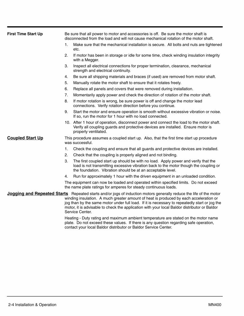
Lubrication Intervals Recommended lubrication intervals are shown in Table 3-1. It is important to realize thatthe recommended intervals of Table 3-1 are based on average use.
Refer to additional information contained in Tables 3-2 and 3-3.
Table 3-1 Lubrication Intervals *
NEMA / (IEC) F SiRated Speed - RPM
NEMA / (IEC) Frame Size 10000 6000 3600 1800 1200 900Up to 210 incl. (132) ** 2700 Hrs. 5500 Hrs. 12000 Hrs. 18000 Hrs. 22000 Hrs.Over 210 to 280 incl. (180) 3600 Hrs. 9500 Hrs. 15000 Hrs. 18000 Hrs.Over 280 to 360 incl. (225) * 2200 Hrs. 7400 Hrs. 12000 Hrs. 15000 Hrs.Over 360 to 5800 incl. (300) *2200 Hrs. 3500 Hrs. 7400 Hrs. 10500 Hrs.
* Lubrication intervals are for ball bearings. For vertically mounted motors and roller bearings, divide the lubricationinterval by 2.
** For 6205 and 6806 bearings. For 6807 bearings, consult oil mist lubrication (MN401). Relubrication interval for 6205 bearing bearing is 1550Hrs. (using grease lubrication).Relubrication interval for 6806 bearing bearing is 720Hrs. (using grease lubrication).

3-2 Maintenance & Troubleshooting MN400
Table 3-2 Service Conditions
Severity of Service Hours per day of Operation
Ambient Temperature Maximum
Atmospheric Contamination
Standard 8 40° C Clean, Little CorrosionSevere 16 Plus 50° C Moderate dirt, CorrosionExtreme 16 Plus >50° C* or
Class H InsulationSevere dirt, Abrasive dust, Corrosion,
Heavy Shock or VibrationLow Temperature <�30° C **
* Special high temperature grease is recommended (Dow Corning DC44). Note that Dow Corning DC44 grease doesnot mix with other grease types. Thoroughly clean bearing & cavity before adding grease.
** Special low temperature grease is recommended (Aeroshell 7).
Table 3-3 Lubrication Interval Multiplier
Severity of Service MultiplierStandard 1.0Severe 0.5Extreme 0.1
Low Temperature 1.0
Table 3-4 Bearings Sizes and Types
Frame SizeNEMA (IEC)
Bearing Description(These are the �Large� bearings (Shaft End) in each frame size)( C)
Bearing ODD mm
WidthB mm
Weight ofGrease to
Volume of greaseto be addedG ease o
add *oz (Grams)
in3 tea-spoon
56 to 180 incl. (63 to 112) 6206 62 16 0.19 (5.0) 0.3 1.0210 incl. (132) 6307 80 21 0.30 (8.4) 0.6 2.0
Over 210 to 280 incl. (180) 6311 120 29 0.61 (17) 1.2 3.9Over 280 to 360 incl. (225) 6313 140 33 0.81 (23) 1.5 5.2Over 360 to 449 incl. (280) 6319 200 45 2.12 (60) 4.1 13.4
Over 5000 to 5800 incl. (355) 6328 300 62 4.70 (130) 9.2 30.0Over 360 to 449 incl. (280) NU319 200 45 2.12 (60) 4.1 13.4
Over 5000 to 5800 incl. (355) NU328 300 62 4.70 (130) 9.2 30.0Spindle Motors
76 Frame 6207 72 17 0.22 (6.1) 0.44 1.477 Frame 6210 90 20 0.32 (9.0) 0.64 2.180 Frame 6213 120 23 0.49 (14.0) 0.99 3.3
* Weight in grams = .005 DB
Note: Not all bearing sizes are listed. For intermediate bearing sizes, use thegrease volume for the next larger size bearing.
Maintenance & Troubleshooting 3-3MN400
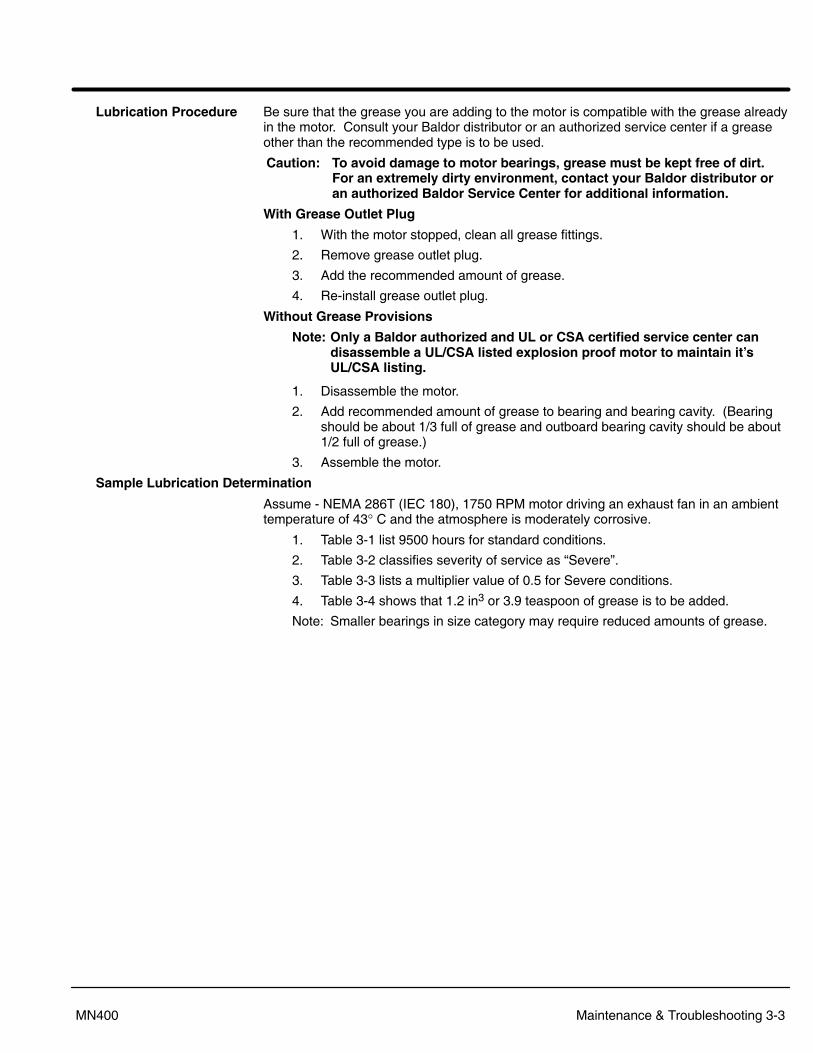
Lubrication Procedure Be sure that the grease you are adding to the motor is compatible with the grease alreadyin the motor. Consult your Baldor distributor or an authorized service center if a greaseother than the recommended type is to be used.
Caution: To avoid damage to motor bearings, grease must be kept free of dirt.For an extremely dirty environment, contact your Baldor distributor oran authorized Baldor Service Center for additional information.
With Grease Outlet Plug
1. With the motor stopped, clean all grease fittings.
2. Remove grease outlet plug.
3. Add the recommended amount of grease.
4. Re-install grease outlet plug.
Without Grease Provisions
Note: Only a Baldor authorized and UL or CSA certified service center candisassemble a UL/CSA listed explosion proof motor to maintain it�sUL/CSA listing.
1. Disassemble the motor.
2. Add recommended amount of grease to bearing and bearing cavity. (Bearingshould be about 1/3 full of grease and outboard bearing cavity should be about1/2 full of grease.)
3. Assemble the motor.
Sample Lubrication Determination
Assume - NEMA 286T (IEC 180), 1750 RPM motor driving an exhaust fan in an ambienttemperature of 43° C and the atmosphere is moderately corrosive.
1. Table 3-1 list 9500 hours for standard conditions.
2. Table 3-2 classifies severity of service as �Severe�.
3. Table 3-3 lists a multiplier value of 0.5 for Severe conditions.
4. Table 3-4 shows that 1.2 in3 or 3.9 teaspoon of grease is to be added.
Note: Smaller bearings in size category may require reduced amounts of grease.
Section 1General Information
3-4 Maintenance & Troubleshooting MN400
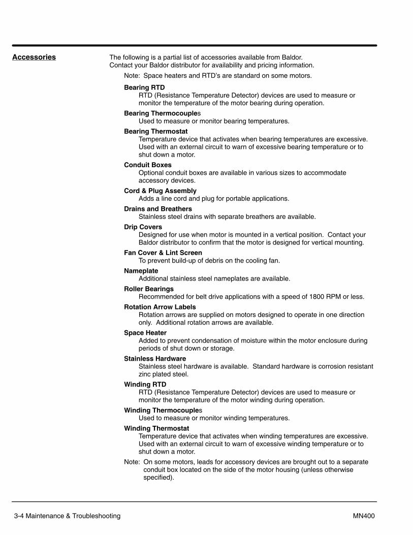
Accessories The following is a partial list of accessories available from Baldor. Contact your Baldor distributor for availability and pricing information.
Note: Space heaters and RTD�s are standard on some motors.
Bearing RTDRTD (Resistance Temperature Detector) devices are used to measure ormonitor the temperature of the motor bearing during operation.
Bearing ThermocouplesUsed to measure or monitor bearing temperatures.
Bearing ThermostatTemperature device that activates when bearing temperatures are excessive.Used with an external circuit to warn of excessive bearing temperature or toshut down a motor.
Conduit BoxesOptional conduit boxes are available in various sizes to accommodateaccessory devices.
Cord & Plug AssemblyAdds a line cord and plug for portable applications.
Drains and BreathersStainless steel drains with separate breathers are available.
Drip CoversDesigned for use when motor is mounted in a vertical position. Contact yourBaldor distributor to confirm that the motor is designed for vertical mounting.
Fan Cover & Lint ScreenTo prevent build-up of debris on the cooling fan.
NameplateAdditional stainless steel nameplates are available.
Roller BearingsRecommended for belt drive applications with a speed of 1800 RPM or less.
Rotation Arrow LabelsRotation arrows are supplied on motors designed to operate in one directiononly. Additional rotation arrows are available.
Space Heater Added to prevent condensation of moisture within the motor enclosure duringperiods of shut down or storage.
Stainless HardwareStainless steel hardware is available. Standard hardware is corrosion resistantzinc plated steel.
Winding RTDRTD (Resistance Temperature Detector) devices are used to measure ormonitor the temperature of the motor winding during operation.
Winding ThermocouplesUsed to measure or monitor winding temperatures.
Winding ThermostatTemperature device that activates when winding temperatures are excessive.Used with an external circuit to warn of excessive winding temperature or toshut down a motor.
Note: On some motors, leads for accessory devices are brought out to a separateconduit box located on the side of the motor housing (unless otherwisespecified).
Section 1General Information
Maintenance & Troubleshooting 3-5MN400
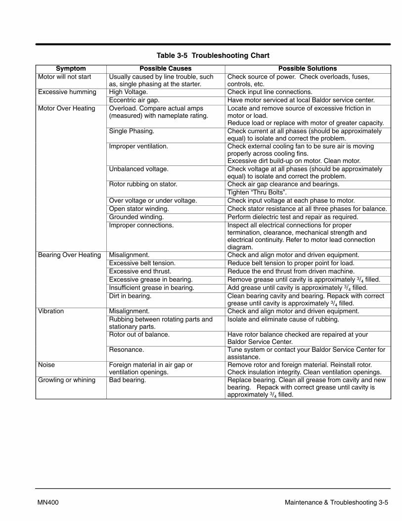
Table 3-5 Troubleshooting Chart
Symptom Possible Causes Possible SolutionsSymptom Possible Causes Possible SolutionsMotor will not start Usually caused by line trouble, such
as, single phasing at the starter.Check source of power. Check overloads, fuses,controls, etc.
Excessive humming High Voltage. Check input line connections.gEccentric air gap. Have motor serviced at local Baldor service center.
Motor Over Heating Overload. Compare actual amps(measured) with nameplate rating.
Locate and remove source of excessive friction inmotor or load.Reduce load or replace with motor of greater capacity.
Single Phasing. Check current at all phases (should be approximatelyequal) to isolate and correct the problem.
Improper ventilation. Check external cooling fan to be sure air is movingproperly across cooling fins.Excessive dirt build-up on motor. Clean motor.
Unbalanced voltage. Check voltage at all phases (should be approximatelyequal) to isolate and correct the problem.
Rotor rubbing on stator. Check air gap clearance and bearings.gTighten �Thru Bolts�.
Over voltage or under voltage. Check input voltage at each phase to motor.Open stator winding. Check stator resistance at all three phases for balance.Grounded winding. Perform dielectric test and repair as required.Improper connections. Inspect all electrical connections for proper
termination, clearance, mechanical strength andelectrical continuity. Refer to motor lead connectiondiagram.
Bearing Over Heating Misalignment. Check and align motor and driven equipment.g gExcessive belt tension. Reduce belt tension to proper point for load.Excessive end thrust. Reduce the end thrust from driven machine.Excessive grease in bearing. Remove grease until cavity is approximately 3/4 filled.Insufficient grease in bearing. Add grease until cavity is approximately 3/4 filled.Dirt in bearing. Clean bearing cavity and bearing. Repack with correct
grease until cavity is approximately 3/4 filled.Vibration Misalignment. Check and align motor and driven equipment.
Rubbing between rotating parts andstationary parts.
Isolate and eliminate cause of rubbing.
Rotor out of balance. Have rotor balance checked are repaired at yourBaldor Service Center.
Resonance. Tune system or contact your Baldor Service Center forassistance.
Noise Foreign material in air gap orventilation openings.
Remove rotor and foreign material. Reinstall rotor.Check insulation integrity. Clean ventilation openings.
Growling or whining Bad bearing. Replace bearing. Clean all grease from cavity and newbearing. Repack with correct grease until cavity isapproximately 3/4 filled.
3-6 Maintenance & Troubleshooting MN400
Suggested bearing and winding RTD setting guidelinesMost large frame AC Baldor motors with a 1.15 service factor are designed to operatebelow a Class B (80°C) temperature rise at rated load and are built with a Class Hwinding insulation system. Based on this low temperature rise, RTD (ResistanceTemperature Detectors) settings for Class B rise should be used as a starting point.Some motors with 1.0 service factor have Class F temperature rise.
The following tables show the suggested alarm and trip settings for RTDs. Properbearing and winding RTD alarm and trip settings should be selected based on thesetables unless otherwise specified for specific applications.
If the driven load is found to operate well below the initial temperature settings undernormal conditions, the alarm and trip settings may be reduced so that an abnormalmachine load will be identified.
The temperature limits are based on the installation of the winding RTDs imbedded in thewinding as specified by NEMA. Bearing RTDs should be installed so they are in contactwith the outer race on ball or roller bearings or in direct contact with the sleeve bearingshell.
Winding RTDs � Temperature Limit In �C (40�C Maximum Ambient)
Motor LoadClass B Temp Rise � 80°C
(Typical Design) Class F Temp Rise � 105°C Class H Temp Rise � 125°CMotor Load
Alarm Trip Alarm Trip Alarm Trip� Rated Load 130 140 155 165 175 185Rated Load to 1.15 S.F.
140 150 160 165 180 185
Note: � Winding RTDs are factory production installed, not from Mod�Express.� When Class H temperatures are used, consider bearing temperatures and lubrication requirements.
Bearing RTDs � Temperature Limit In OC with 40�C Max Ambient
Bearing Type Anti�Friction SleeveBearing TypeOil or Grease Alarm Trip Alarm Trip
Standard* 95 100 85 95High Temperature** 110 115 105 110
Note: * Bearing temperature limits are for standard design motors operating at Class B temperature rise.** High temperature lubricants include some special synthetic oils and greases.
Greases that may be substituted that are compatible with Polyrex EM (but considered as �standard�lubricants) include the following: � Texaco Polystar � Rykon Premium #2 � Chevron SRI #2
See the motor nameplate for replacement grease or oil recommendation. Contact Baldorapplication engineering for special lubricants or further clarifications.
BALDOR ELECTRIC COMPANYP.O. Box 2400
Ft. Smith, AR 72902�2400(479) 646�4711
Fax (479) 648�5792
© Baldor Electric CompanyMN400
Printed in USA5/04 C&J10000
CHTEL:+41 52 647 4700FAX:+41 52 659 2394
DTEL:+49 89 90 50 80FAX:+49 89 90 50 8491
UKTEL:+44 1454 850000FAX:+44 1454 850001
ITEL:+39 11 562 4440FAX:+39 11 562 5660
AUTEL:+61 29674 5455FAX:+61 29674 2495
FTEL:+33 145 10 7902FAX:+33 145 09 0864
CCTEL:+65 744 2572FAX:+65 747 1708
MX���� ��������� �
���� ��������� �
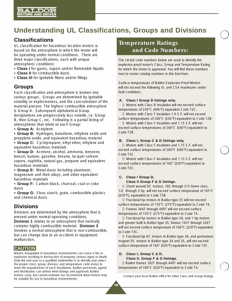
Understanding UL Classifications, Groups and DivisionsClassificationsUL classification for hazardous location motors is based on the atmosphere in which the motor will be operating under normal conditions. There are three major classifications, each with uniqueatmospheric conditions:• Class I for gases, vapors and/or flammable liquids• Class II for combustible dusts• Class III for ignitable fibers and/or filings
GroupsEach classification and atmosphere is broken intovarious groups. Groups are determined by ignitablevolatility or explosiveness, and the concentration of thematerial present. The highest combustible atmosphereis Group A. Subsequent alphabetical Groupdesignations are progressively less volatile, i.e. GroupB, then Group C, etc. Following is a partial listing ofatmospheres that relate to each Group:• Group A: Acetylene• Group B: Hydrogen, butadiene, ethylene oxide andpropylene oxide, and equivalent hazardous material• Group C: Cyclopropane, ethyl ether, ethylene andequivalent hazardous materials• Group D: Acetone, alcohol, ammonia, benzene,benzol, butane, gasoline, hexane, lacquer solventvapors, naphtha, natural gas, propane and equivalenthazardous materials• Group E: Metal dusts including aluminum,magnesium and their alloys, and other equivalenthazardous materials• Group F: Carbon black, charcoal, coal or cokedusts• Group G: Flour, starch, grain, combustible plasticsand chemical dusts
DivisionsDivisions are determined by the atmosphere that ispresent under normal operating conditions. Division 1 relates to an atmosphere that normallycontains highly combustible material. Division 2involves a normal atmosphere that is non-combustible,but can change due to an accident or equipmentmalfunction.
CAUTIONMotors misapplied in hazardous environments can cause a fire orexplosion resulting in destruction of property, serious injury or death.Only the end user or a qualified underwriter is to identify and selectthe proper class, group, division, and temperature code motor tomeet the requirements of each installation. Baldor personnel, agentsand distributors can advise what listings and approvals Baldormotors carry, but cannot evaluate nor recommend what motors maybe suitable for use in hazardous environments.
Temperature Ratings and Code Numbers:
The circled code numbers below are used to identify theexplosion-proof motor’s Class, Group and Temperature Ratingfor which the motor is approved. You will find these numbersnext to motor catalog numbers in this brochure.
Surface temperatures of Baldor Explosion-Proof Motors will not exceed the following UL and CSA maximums under fault conditions.
A. Class I Group D listings only.① Motors with Class B insulation will not exceed surface
temperatures of 230°C (446°F) equivalent Code T2C.➅ Motors with Class F insulation 1.0 S.F. will not exceed
surface temperatures of 260°C (536°F) equivalent to Code T2B.⑨ Motors with Class F insulation and 1.15 S.F. will not
exceed surface temperatures of 260°C (500°F) equivalent toCode T2B.
B. Class I, Group C & D listings only.⑤ Motors with Class F insulation and 1.15 S.F. will not
exceed surface temperatures of 260°C (500°F) equivalent toCode T3C.
⑨ Motors with Class F insulation and 1.15 S.F. will notexceed surface temperatures of 160° (320°F) equivalent toCode T3C.
C. Class I Group D,Class II Group F & G listings.
③ Shunt wound DC motors, 182 through 215 frame sizes,1/2 through 3 hp, will not exceed surface temperature of 165°C(329°F), equivalent to Code T3B.
⑦ Fractional hp motors in Baldor type 35 will not exceedsurface temperatures of 135°C (275°F) equivalent to Code T4.
⑦ Frames 364T through 449T will not exceed surfacetemperatures of 135°C (275°F) equivalent to Code T4.
⑧ Fractional hp motors in Baldor type 34, and 1 hp motorsand greater built in Baldor type 35, frames 143T through 326Twill not exceed surface temperature of 160°C (320°F) equivalentto Code T3C.
⑧ Fractional hp AC motors in Baldor type 34, and permanentmagnet DC motors in Baldor type 34 and 35, will not exceedsurface temperature of 160° (320°F) equivalent to Code T3C.
D. Class I, Group C & D,Class II, Group F & G listings.
② Baldor frames 182T through 449T will not exceed surfacetemperatures of 160°C (320°F) equivalent to Code T4.
Contact your local Baldor office for other Class and Group listings.
10
www.baldor.com13
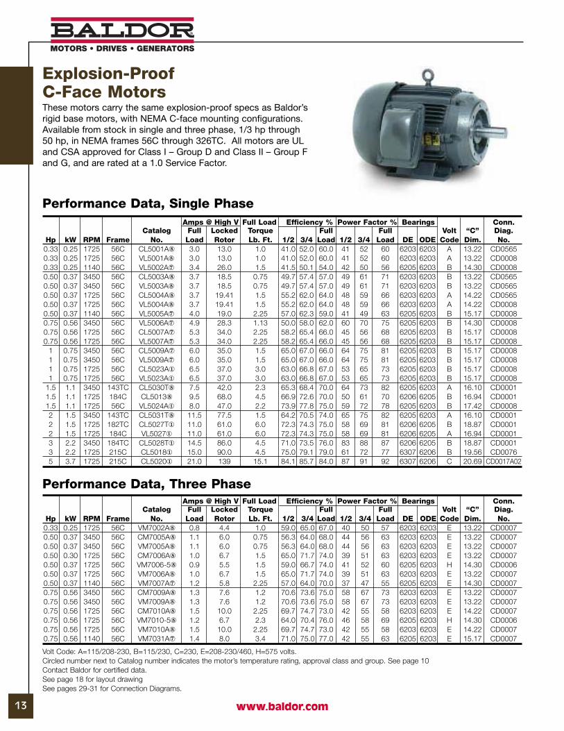
Amps @ High V Full Load Efficiency % Power Factor % Bearings Conn.Catalog Full Locked Torque Full Full Volt “C” Diag.
Hp kW RPM Frame No. Load Rotor Lb. Ft. 1/2 3/4 Load 1/2 3/4 Load DE ODE Code Dim. No.0.33 0.25 1725 56C CL5001A� 3.0 13.0 1.0 41.0 52.0 60.0 41 52 60 6203 6203 A 13.22 CD05650.33 0.25 1725 56C VL5001A� 3.0 13.0 1.0 41.0 52.0 60.0 41 52 60 6203 6203 A 13.22 CD00080.33 0.25 1140 56C VL5002A� 3.4 26.0 1.5 41.5 50.1 54.0 42 50 56 6205 6203 B 14.30 CD00080.50 0.37 3450 56C CL5003A� 3.7 18.5 0.75 49.7 57.4 57.0 49 61 71 6203 6203 B 13.22 CD05650.50 0.37 3450 56C VL5003A� 3.7 18.5 0.75 49.7 57.4 57.0 49 61 71 6203 6203 B 13.22 CD05650.50 0.37 1725 56C CL5004A� 3.7 19.41 1.5 55.2 62.0 64.0 48 59 66 6203 6203 A 14.22 CD05650.50 0.37 1725 56C VL5004A� 3.7 19.41 1.5 55.2 62.0 64.0 48 59 66 6203 6203 A 14.22 CD00080.50 0.37 1140 56C VL5005A� 4.0 19.0 2.25 57.0 62.3 59.0 41 49 63 6205 6203 B 15.17 CD00080.75 0.56 3450 56C VL5006A� 4.9 28.3 1.13 50.0 58.0 62.0 60 70 75 6205 6203 B 14.30 CD00080.75 0.56 1725 56C CL5007A� 5.3 34.0 2.25 58.2 65.4 66.0 45 56 68 6205 6203 B 15.17 CD00080.75 0.56 1725 56C VL5007A� 5.3 34.0 2.25 58.2 65.4 66.0 45 56 68 6205 6203 B 15.17 CD0008
1 0.75 3450 56C CL5009A� 6.0 35.0 1.5 65.0 67.0 66.0 64 75 81 6205 6203 B 15.17 CD00081 0.75 3450 56C VL5009A� 6.0 35.0 1.5 65.0 67.0 66.0 64 75 81 6205 6203 B 15.17 CD00081 0.75 1725 56C CL5023A� 6.5 37.0 3.0 63.0 66.8 67.0 53 65 73 6205 6203 B 15.17 CD00081 0.75 1725 56C VL5023A� 6.5 37.0 3.0 63.0 66.8 67.0 53 65 73 6205 6203 B 15.17 CD0008
1.5 1.1 3450 143TC CL5030T� 7.5 42.0 2.3 65.3 68.4 70.0 64 73 82 6205 6203 A 16.10 CD00011.5 1.1 1725 184C CL5013� 9.5 68.0 4.5 66.9 72.6 70.0 50 61 70 6206 6205 B 16.94 CD00011.5 1.1 1725 56C VL5024A� 8.0 47.0 2.2 73.9 77.8 75.0 59 72 78 6205 6203 B 17.42 CD00082 1.5 3450 143TC CL5031T� 11.5 77.5 1.5 64.2 70.5 74.0 65 75 82 6205 6203 A 16.10 CD00012 1.5 1725 182TC CL5027T� 11.0 61.0 6.0 72.3 74.3 75.0 58 69 81 6206 6205 B 18.87 CD00012 1.5 1725 184C VL5027� 11.0 61.0 6.0 72.3 74.3 75.0 58 69 81 6206 6205 A 16.94 CD00013 2.2 3450 184TC CL5028T� 14.5 86.0 4.5 71.0 73.5 76.0 83 88 87 6206 6205 B 18.87 CD00013 2.2 1725 215C CL5018� 15.0 90.0 4.5 75.0 79.1 79.0 61 72 77 6307 6206 B 19.56 CD00765 3.7 1725 215C CL5020� 21.0 139 15.1 84.1 85.7 84.0 87 91 92 6307 6206 C 20.69 CD0017A02
Performance Data, Single Phase
Volt Code: A=115/208-230, B=115/230, C=230, E=208-230/460, H=575 volts.Circled number next to Catalog number indicates the motor’s temperature rating, approval class and group. See page 10 Contact Baldor for certified data.See page 18 for layout drawingSee pages 29-31 for Connection Diagrams.
Performance Data, Three PhaseAmps @ High V Full Load Efficiency % Power Factor % Bearings Conn.
Catalog Full Locked Torque Full Full Volt “C” Diag.Hp kW RPM Frame No. Load Rotor Lb. Ft. 1/2 3/4 Load 1/2 3/4 Load DE ODE Code Dim. No.
0.33 0.25 1725 56C VM7002A� 0.8 4.4 1.0 59.0 65.0 67.0 40 50 57 6203 6203 E 13.22 CD00070.50 0.37 3450 56C CM7005A� 1.1 6.0 0.75 56.3 64.0 68.0 44 56 63 6203 6203 E 13.22 CD00070.50 0.37 3450 56C VM7005A� 1.1 6.0 0.75 56.3 64.0 68.0 44 56 63 6203 6203 E 13.22 CD00070.50 0.30 1725 56C CM7006A� 1.0 6.7 1.5 65.0 71.7 74.0 39 51 63 6203 6203 E 13.22 CD00070.50 0.37 1725 56C VM7006-5� 0.9 5.5 1.5 59.0 66.7 74.0 41 52 60 6205 6203 H 14.30 CD00060.50 0.37 1725 56C VM7006A� 1.0 6.7 1.5 65.0 71.7 74.0 39 51 63 6203 6203 E 13.22 CD00070.50 0.37 1140 56C VM7007A� 1.2 5.8 2.25 57.0 64.0 70.0 37 47 55 6205 6203 E 14.30 CD00070.75 0.56 3450 56C CM7009A� 1.3 7.6 1.2 70.6 73.6 75.0 58 67 73 6203 6203 E 13.22 CD00070.75 0.56 3450 56C VM7009A� 1.3 7.6 1.2 70.6 73.6 75.0 58 67 73 6203 6203 E 13.22 CD00070.75 0.56 1725 56C CM7010A� 1.5 10.0 2.25 69.7 74.7 73.0 42 55 58 6203 6203 E 14.22 CD00070.75 0.56 1725 56C VM7010-5� 1.2 6.7 2.3 64.0 70.4 76.0 46 58 69 6205 6203 H 14.30 CD00060.75 0.56 1725 56C VM7010A� 1.5 10.0 2.25 69.7 74.7 73.0 42 55 58 6203 6203 E 14.22 CD00070.75 0.56 1140 56C VM7031A� 1.4 8.0 3.4 71.0 75.0 77.0 42 55 63 6205 6203 E 15.17 CD0007
Explosion-Proof C-Face MotorsThese motors carry the same explosion-proof specs as Baldor’srigid base motors, with NEMA C-face mounting configurations.Available from stock in single and three phase, 1/3 hp through50 hp, in NEMA frames 56C through 326TC. All motors are ULand CSA approved for Class I – Group D and Class II – Group Fand G, and are rated at a 1.0 Service Factor.

def
Motors, For Use In Hazardous Locations
Class I, Group C and D; Class II, Groups E, F and G.
Class I, Group D; Class II, Groups E, F, and Gmotors with Listed brakes. The brakes in these explosion-proof and dust ignition proof assemblies are intended essentially for holding purposes and may be used for stopping light inertia loads.
Class I, Group D; Class II, Groups F and Gmotors for use with pulse width modulated variable frequency inverter drives over the frequency range of 6 to 90 HZ .
Class I, Group Dmotors for use with voltage source, current source and pulse width modulated variable frequency inverter drives over the frequency range of 0 to 120 HZ .
This page and all contents are Copyright © 2003 by Underwriters Laboratories Inc.®
The appearance of a company's name or product in this database does not in itself assure that products so identified have been manufactured under UL's Follow-Up Service. Only those products bearing the UL Mark should be considered to be Listed and covered under UL's Follow-Up Service. Always look for the Mark on the product.
UL permits the reproduction of the material contained on UL's Website subject to the following conditions: 1. The Guide Information, Designs and/or Listings (files) must be presented in their entirety and in a non-misleading manner, without any manipulation of the data (or drawings). 2. The statement "Reprinted from the Online Certifications Directory with permission from Underwriters Laboratories Inc." must appear adjacent to the extracted material. In addition, the reprinted material must include a copyright notice in the following format: "Copyright © 2003 Underwriters Laboratories Inc.®"
PTDR.E6951 Motors, For Use In Hazardous Locations
Page Bottom Questions? Previous Page
Guide Information BALDOR ELECTRIC CO E69515711 R S BOREHAM, JR STFT SMITH, AR 72908 USA
Page Top Notice of Disclaimer Questions? Previous Page
UL Listed and Classified Products
UL Recognized Components
Products Certified for Canada
Page 1 of 1PTDR.E6951 - Motors, For Use In Hazardous Locations
8/26/2003http://database.ul.com/cgi-bin/XYV/template/LISEXT/1FRAME/showpage.html?name=P...

Control Panels and Assemblies for Use in Hazardous Locations
Class I, Groups B, C and D; Class II, Groups E, F and G.
Cover/sealing chamber assembly, Cat. No. EFSR-GFI.
Body assemblies, Cat. Nos. EFD, EFDC followed by 110, 150 or 175, with or without suffix letter A, followed by NL, may be followed by Q.
Cover assembly, Cat. No. EFK followed by F12Q, F34WQ, L3HQ, R12Q or R34WQ.
Cover assembly, Cat. No. ESKB followed by 1PBQ, 2PBQ, 2SPQ or 3JPBQ.
Class I, Groups B, C and D; Class II, Groups F and G.
Cover assembly, Cat. No. EFSR followed by 2023 or 20232, with or without M, may be followed by Model B.
Class I, Groups C and D; Class II, Groups E, F and G.
Cover assemblies, Cat. No. EDK followed by F12, F34W, R12 or R34W, RU1, RU2 or ROC, with or without A, may be followed by Q, with or without A; Cat. No. EFK followed by F12, R12, F34W or R34W, with or without A, , may be followed by Q; Cat. No. EDK or EFK followed by OMS, with or without A, , may be followed by Q; Cat. No. EFK followed by MOHC, MU, MU2, RU1, RU2 or ROC, may be followed by Q; Cat. No. EFK followed by 12, 35, 102, 345, U1, U2, J1, J1-TR2, J1-TR4, J1-TR5, J2, JU2, J1U1, J1U2, J17W, OC, DU1 or DU2, may be followed by Q; Cat. No. EFKB followed by -12, -35, -102, -102ML, -102MR, -102SRC, -345, -345ML, -345MR, -345SRC, -637, -DU1, -DU2, -J1, -J1DU1, -J1U1, -J1U2, -J2, -OC, -PC120, -PC277, -U1, -U2 or -UM1; Cat. No. ESK followed by B, may be followed by Q; Cat. No. EFKL followed by J1DU2, J1U2, J2U1, J3 or U3.
NNNY.E81751 Control Panels and Assemblies for Use in Hazardous Locations
Page Bottom Questions? Previous Page
Guide Information
APPLETON ELECTRIC L L C E817517770 N FRONTAGE RDSKOKIE, IL 60077 USA
Page 1 of 4NNNY.E81751 - Control Panels and Assemblies for Use in Hazardous Locations
9/19/2003http://database.ul.com/cgi-bin/XYV/template/LISEXT/1FRAME/showpage.html?name=N...
Cover/sealing chamber assemblies, Cat. Nos. EDK-F21, -F22, -F23W, -F24W, -F31, -F32, -F33W, -R21, -R22, -R23W, -R24W, -R31, -R32 or -R33W with or without A, may be followed by Q.
Cover/factory sealed snap switches, Cat. Nos. EDK-F21, -F22, -F23W, -R21, -R22, -R23W with or without A, may be followed by Q.
Cover assemblies: Cat. No. EDK followed by -DPB, -MOC, -MU or -MU2, may be followed by A; Cat. Nos. EDK-2MS, -2MSA, -3MS or 3MSA followed by -Q; Cat. No. EDKB followed by -PC120 or -PC277, may be followed by A; Cat. No. EDSK followed by -1J, -1JSS, -2J, -2SP, -B, -MS, -RU1, -RU2, -ROC, may be followed by A; Cat. No. EDSKL-3PB may be followed by suffix letter A; Cat. No. EFDLfollowed by J1U2, J2U1, J3, U3, may be followed by suffix letter A.
Body assemblies: Cat. No. EDS or EDSC followed by -147, -171, -172, -177, -247, -271, -272, -277, -347, -371, -372 or -377, may be followed by SA; Cat. No. EFS, EFSC, EFD or EFDC followed by 110, 150, 175, 210, 250 or 275, with or without A, may be followed by NL, may be followed by Q; Cat. No. EFDL or EFDCL followed by 10, 50 or 75, may be followed by Q. Series EFDCT, EFDT, Cat. Nos. EFDCT or EFDT followed by -10, -50 or -75; may be followed by -NL and/or -Q.
Sealing chambers: Cat. No. EDS-F followed by 21-Q, 22-Q, 23W-Q, 24-W-Q, 31-Q, 32-Q or 33W-Q; Cat. No. EDSK followed by -1MSAB-Q, -2MSAB-Q, -1MSW-Q, or -2MSW-Q; Cat. No. SW followed by FR1, FR2, FR13, FR23, FR3W, FR4W or FR3W3, may be followed by Q; Cat. No. SW followed by 1MSAB, 1MSW, 2MSAB or 2MSW.
Cat. No. SW followed by RU1, RU2 or ROC, may be followed by Q; Cat. No. GFS-1.
Blank covers: Cat. Nos. ESK-B-Q, ESKB-B-Q.
Cover assembly non-factory sealed: Cat. No. EDS-F followed by -12-A or -34W-A; Cat. No. EFS-FR followed by 1, 2, 3W or 4W, followed by -Q.
Cover assembly: factory sealed, Cat. No. EDS-F, followed by 21-Q, 22-Q or 23W-Q.
Class I, Groups C and D.
Cover assembly: Cat. No. N1K followed by -1PL, -2PL, -2SP, -3JPB, -12, -35, -102, -345, -F12Q, -F34WQ, -G37SRC, -J1, -J1U1, -J2, -J12, -J35, -J102, -J345, -JG37SRC, -JU2, -U1, -U2, -U3 OR -UM1.
Class I, Groups B, C and D, Division 2; Class II, Groups E, F and G; Class III.
Cover assembly: Cat. No. N2K followed by -1PL, -2PL, -2SP, -3JPB, -12, -35, -102, -345, -G37SRC, -J1, -J1U1, -J2, -J12, -J35, -J102, -J345, -JG37SRC, -JU2, -U1, -U2, -U3 or -UM1.
Cover assembly with push buttons and/or selector switches and pilot lights: Cat. No. ED2KB or ED2SK followed by one or more suffixes 12, 35, 102, 345, B, DC, J1, J2, PLG, U1, U2, UD1, UDM1, UM1, may be followed by ALT, JGBA, JGBB, JGBG, NMRBBL, NMRBBU, NMRBGR, NMRBGY, NMRBMBL, NMRBMBU, NMRBMGR, NMRBMGY, NMRBMRE, NMRBMWT, NMRBMYL, NMRBRE, NMRBWT, NMRBYL, PBBU, PBGR, PBGY, PBRE, PBWT, PBYL, SLC, SRC or SRL, may be followed by UCLP or UCPLP.
Cover assembly with push buttons and/or selector switches: Cat. No. ED2KB or ED2SK followed by
Page 2 of 4NNNY.E81751 - Control Panels and Assemblies for Use in Hazardous Locations
9/19/2003http://database.ul.com/cgi-bin/XYV/template/LISEXT/1FRAME/showpage.html?name=N...
one or more suffixes 12, 35, 102, 345, B, U1, U2, UD1, UDM1 or UM1, may be followed by ALT, NMRBBL, NMRBBU, NMRBGR, NMRBGY, NMRBMBL, NMRBMBU, NMRBMGR, NMRBMGY, NMRBMRE, NMRBMWT, NMRBMYL, NMRBRE, NMRBWT, NMRBYL, PBBU, PBGR, PBGY, PBRE, PBWT, PBYL, SLC, SRC or SRL, may be followed by UCLP.
Cover assembly with pilot lights: Cat. No. ED2KB or ED2SK followed by one or more suffixes B, DC, J1, J2 or PLG, may be followed by JGBA, JGBB or JGBG, may be followed by UCPLP.
Cat. No. EDS or EDSC followed by 1, 2 or 3, followed by 71, 72 or 77, may be followed by SA.
Blank cover: Cat. No. ED2SK followed by 1 or 2.
Mounting body: Cat. No. EDS or EDSC followed by 1, 2 or 3, followed by 71, 72 or 77, may be followed by SA.
Cover assembly with push buttons and/or selector switches and pilot lights: Cat. No. UCSK followed by one or more suffixes DC, HSW, HSWNC, HSWNO, J1, J2, J3, J4, PLG, U1, U2, U3, U4, UD1, UDM1, UM1, may be followed by ALT, JGBA, JGBB, JGBG, NMRBBL, NMRBBU, NMRBGR, NMRBGY, NMRBMBU, NMRBMDD, NMRBMGR, NMRBMGY, NMRBMWT, NMRBMYL, NMRBRE, NMRBWT, NMRBYL, PBBU, PBGR, PBGY, PBRE, PBWT, PBYL, SLC, SRC, or SRL, may be followed by UCLP or UCPLP.
Cover assembly with push buttons and/or selector switches: Cat. No. UCSK followed by one or more suffixes 12, 35, 102, 345, HSW, HSWNC, HSWNO, PLG, U1, U2, U3, U4, UD1, UDM1 or UM1, may be followed by ALT, NMRBBL, NMRBBU, NMRBGR, NMRBGY, NMRBMBL, NMRBMBU, NMRBMGR, NMRBMGY, NMRBMWT, NMRBMYL, NMRBRE, NMRBWT, NMRBYL, PBBU, PBGR, PBGY, PBRE, PBWT, PBYL, SLC, SRC, SRL, may be followed by UCLP.
Cover assembly with pilot lights: Cat. No. UCSK followed by one or more suffixes DC, J1, J2, J3, J4 or PLG, may be followed by JGBA, JGBB or JGBG, may be followed by UCPLP.
Cover only (without devices): Cat. No. UCC followed by 1, 2, 3 or 4.
Mounting body: Cat. No. UCBB or UCBBC followed by 2, 3 or 4, followed by 10, 50 or 75, may be followed by U.
Class I, Groups C and D; Class II, Groups E, F and G; Class I, Group B, Division 2.
Cover assemblies: Cat. No. EDKB followed by -12, -35, -102, -345, -637-SRC, -DU1, -DU2, -J1, -J1DU1, -J1TR2, -J1TR3, -J1TR4, -J1TR5, -J1U1, -J1U2, -J2, -ML2, -ML4, -MR2, -MR4, -OC, -U1, -U2, DPB, DPBM, RU1, RU2 or -SMPB, may be followed by A.
Cat. No. EDSK followed by -B, -SMPB, may be followed by A.
Cat. No. EDSKN followed by DPB, DPBM, RU1, RU2, may be followed by suffix letter A.
Class I, Division 2, Groups B, C, D; Class II, Division 2, Groups F and G; Class III, Type 3, 3R, 4, 4X (Aluminium version only), 12.
Cover assemblies with snap switches: Cat. No. FDK2 followed by -F1, -F2, -F3W, -F1A, -F2A or -
Page 3 of 4NNNY.E81751 - Control Panels and Assemblies for Use in Hazardous Locations
9/19/2003http://database.ul.com/cgi-bin/XYV/template/LISEXT/1FRAME/showpage.html?name=N...
F3WA.
LOOK FOR LISTING MARK ON PRODUCT
This page and all contents are Copyright © 2003 by Underwriters Laboratories Inc.®
The appearance of a company's name or product in this database does not in itself assure that products so identified have been manufactured under UL's Follow-Up Service. Only those products bearing the UL Mark should be considered to be Listed and covered under UL's Follow-Up Service. Always look for the Mark on the product.
UL permits the reproduction of the material contained on UL's Website subject to the following conditions: 1. The Guide Information, Designs and/or Listings (files) must be presented in their entirety and in a non-misleading manner, without any manipulation of the data (or drawings). 2. The statement "Reprinted from the Online Certifications Directory with permission from Underwriters Laboratories Inc." must appear adjacent to the extracted material. In addition, the reprinted material must include a copyright notice in the following format: "Copyright © 2003 Underwriters Laboratories Inc.®"
Page Top Notice of Disclaimer Questions? Previous Page
UL Listed and Classified Products
UL Recognized Components
Products Certified for Canada
Page 4 of 4NNNY.E81751 - Control Panels and Assemblies for Use in Hazardous Locations
Related Documents


![FIRST CLASS SEATS FOR EVERYONE€¦ · [1] Connection box for water supply Sensia IGS and Sensia Arena [2] Water connection for Sensia IGS [3] Protection block for flush pipe and](https://static.cupdf.com/doc/110x72/5fd090aabe60cf457f742a25/first-class-seats-for-everyone-1-connection-box-for-water-supply-sensia-igs-and.jpg)


