Technical Documentation Diesel Engine 12 V 4000 G23, G43 12 V 4000 G63, G83 16 V 4000 G23, G43 16 V 4000 G63, G83 Operating Instructions M015710/01E

Manual Mantenimiento MTU
Sep 30, 2014
Welcome message from author
This document is posted to help you gain knowledge. Please leave a comment to let me know what you think about it! Share it to your friends and learn new things together.
Transcript
Technical Documentation
Diesel Engine 12 V 4000 G23, G43 12 V 4000 G63, G83 16 V 4000 G23, G43 16 V 4000 G63, G83 Operating Instructions M015710/01E

Printed in Germany© 2007 Copyright MTU Friedrichshafen GmbHThis Publication is protected by copyright and may not be used in any way whether in whole or in part without theprior written permission of MTU Friedrichshafen GmbH. This restriction also applies to copyright, distribution,translation, microfilming and storage or processing on electronic systems including data bases and online services.This handbook is provided for use by maintenance and operating personnel in order to avoid malfunctions ordamage during operation.Subject to alterations and amendments.
Wichtig – Important – Importante
Bitte die Karte „Inbetriebnahmemeldung“ abtrennen und ausgefüllt an MTU Friedrichshafen GmbH zurücksenden.
Die Informationen der Inbetriebnahmemeldung sind Grundlage für den vertraglich vereinbarten Logistik- Support (Gewährleistung, Ersatzteile etc.).
Please complete and return the “Commissioning Note” card below to MTU Friedrichshafen GmbH.
The Commissioning Note information serves as a basis for the contractually agreed logistic support (warranty, spare parts, etc.).
Veuillez séparer la carte “Signalisation de mise en service“ et la renvoyer à la MTU Friedrichshafen GmbH.
Les informations contenues dans la signalisation de mise en service constituent la base pour l'assistance en exploitation contractuelle (garantie, rechanges, etc.).
Rogamos separen la tarjeta “Aviso de puesta en servicio“ y la devuelvan rellenada a MTU Friedrichshafen GmbH.
Las informaciones respecto al aviso de puesta en servicio constituyen la base para el soporte logístico contractual (garantía, piezas de repuesto, etc.).
Ritagliare “Avviso di messa in servizio“ e rispedirlo debitamente compilato alla MTU Friedrichshafen GmbH.
Le informazioni ivi registrate sono la base per il supporto logistico contrattuale (garanzia, ricambi, ecc.).
É gentileza cortar o cartão "Participação da colocação em serviço", preenché-lo e devolvé-lo a MTU Friedrichshafen.
Os dados referentes à colocação em serviço representam a base para o suporte logístico (garantia, peças sobressalentes, etc.) estabelecido contratualmente.
Postcard
MTU Friedrichshafen GmbH
Department MST
88040 Friedrichshafen
GERMANY

Bitte in Blockschrift ausfüllen! Please use block capitals! Prière de remplir en lettres capitales! ¡A rellenar en letras de imprenta! Scrivere in stampatello! Favor preencher com letras de forma!
Motornr.: Engine No.: No du moteur: No de motor: Motore N.: No. do motor:
Auftragsnr.:MTU works order No.: N° de commande: N° de pedido: N. commessa: No. do pedido:
Motortyp:
Engine model: Type du moteur: Tipo de motor: Motore tipo: Tipo do motor:
Inbetriebnahmedatum:Date put into operation: Mise en service le: Fecha de puesta en servicio: Messa in servizio il: Data da colocação em serviço:
Eingebaut in:
Installation site: Lieu de montage: Lugar de montaje: Installato: Incorporado em:
Schiffstyp / Schiffshersteller:Vessel/type/class / Shipyard: Type du bateau / Constructeur: Tipo de buque / Constructor: Tipo di barca / Costruttore Tipo de embarcação/estaleiro naval:
Endabnehmer/Anschrift:
End user`s address: Adresse du client final: Dirección del cliente final: Indirizzo del cliente finale: Usuário final/endereço:
Bemerkung:
Remarks: Remarques: Observaciones: Commento: Observações:
Inbetriebnahme-meldung Commissioning Note Notice de mise en service Aviso de puesta en servicio Avviso di messa in servizio Participação da colocação em serviço
Table of Contents 01
1 Safety . . . . . . . . . . . . . . . . . . . . . . . . . . . . . . . . . . . . . . . . . . . . . . . . . . . . . . . . . . . . . . . . . . . . . . . . 05
1.1 General conditions . . . . . . . . . . . . . . . . . . . . . . . . . . . . . . . . . . . . . . . . . . . . . . . . . . . . . . . 05
1.2 Personnel and organizational requirements . . . . . . . . . . . . . . . . . . . . . . . . . . . . . . . . . . 06
1.3 Transport . . . . . . . . . . . . . . . . . . . . . . . . . . . . . . . . . . . . . . . . . . . . . . . . . . . . . . . . . . . . . . . 07
1.4 Safety requirements when working on the engine . . . . . . . . . . . . . . . . . . . . . . . . . . . . . 08
1.5 Auxiliary materials, fire prevention and environmental protection . . . . . . . . . . . . . . . . 11
1.6 Standards for warning notices in the publication . . . . . . . . . . . . . . . . . . . . . . . . . . . . . . 13
2 Product Summary . . . . . . . . . . . . . . . . . . . . . . . . . . . . . . . . . . . . . . . . . . . . . . . . . . . . . . . . . . . . . . 15
2.1 Engine Layout . . . . . . . . . . . . . . . . . . . . . . . . . . . . . . . . . . . . . . . . . . . . . . . . . . . . . . . . . . . 152.1.1 Engine layout . . . . . . . . . . . . . . . . . . . . . . . . . . . . . . . . . . . . . . . . . . . . . . . . . . . . 15
2.2 Engine Side and Cylinder Designations . . . . . . . . . . . . . . . . . . . . . . . . . . . . . . . . . . . . . . 172.2.1 Engine side and cylinder designations . . . . . . . . . . . . . . . . . . . . . . . . . . . . . . . . . 17
2.3 Main Engine Dimensions . . . . . . . . . . . . . . . . . . . . . . . . . . . . . . . . . . . . . . . . . . . . . . . . . . 182.3.1 Engine – Main dimensions . . . . . . . . . . . . . . . . . . . . . . . . . . . . . . . . . . . . . . . . . . 18
2.4 Firing Order . . . . . . . . . . . . . . . . . . . . . . . . . . . . . . . . . . . . . . . . . . . . . . . . . . . . . . . . . . . . . 192.4.1 Firing order . . . . . . . . . . . . . . . . . . . . . . . . . . . . . . . . . . . . . . . . . . . . . . . . . . . . . . 19
2.5 Final Compression Pressure . . . . . . . . . . . . . . . . . . . . . . . . . . . . . . . . . . . . . . . . . . . . . . . 202.5.1 Final compression pressure . . . . . . . . . . . . . . . . . . . . . . . . . . . . . . . . . . . . . . . . . 20
2.6 Technical Data . . . . . . . . . . . . . . . . . . . . . . . . . . . . . . . . . . . . . . . . . . . . . . . . . . . . . . . . . . 212.6.1 12V 4000 Gx3 engine data: Standby operation 3D, optimized fuel consumption
. . . . . . . . . . . . . . . . . . . . . . . . . . . . . . . . . . . . . . . . . . . . . . . . . . . . . . . . . . . . . . . 212.6.2 16V 4000 Gx3 engine data: Standby operation 3D, optimized fuel consumption
. . . . . . . . . . . . . . . . . . . . . . . . . . . . . . . . . . . . . . . . . . . . . . . . . . . . . . . . . . . . . . . 262.6.3 Engine data 12/16V 4000 Gx3: Standby operation 3D, optimized exhaust
emissions (EPA stage 2) . . . . . . . . . . . . . . . . . . . . . . . . . . . . . . . . . . . . . . . . . . . 312.6.4 12V 4000 Gx3 engine data: Continuous operation, variable 3B, optimized fuel
consumption . . . . . . . . . . . . . . . . . . . . . . . . . . . . . . . . . . . . . . . . . . . . . . . . . . . . 362.6.5 16V 4000 Gx3 engine data: Continuous operation, variable 3B, optimized fuel
consumption . . . . . . . . . . . . . . . . . . . . . . . . . . . . . . . . . . . . . . . . . . . . . . . . . . . . 412.6.6 12/16 V 4000 Gx3 engine data: Continuous operation, variable 3B, optimized
exhaust emission (EPA stage 2) . . . . . . . . . . . . . . . . . . . . . . . . . . . . . . . . . . . . . . 462.6.7 12V 4000 Gx3 engine data: Continuous operation, variable 3B, optimized exhaust
emissions (TA-Luft) . . . . . . . . . . . . . . . . . . . . . . . . . . . . . . . . . . . . . . . . . . . . . . . . 51
3 Operation . . . . . . . . . . . . . . . . . . . . . . . . . . . . . . . . . . . . . . . . . . . . . . . . . . . . . . . . . . . . . . . . . . . . . 55
3.1 Putting the engine into operation after extended out-of-service-periods (>3months) . . . . . . . . . . . . . . . . . . . . . . . . . . . . . . . . . . . . . . . . . . . . . . . . . . . . . . . . . . . . . . . . 55
3.2 Putting the engine into operation after scheduled out-of-service-period . . . . . . . . . . . 56
3.3 Starting the engine in manual mode . . . . . . . . . . . . . . . . . . . . . . . . . . . . . . . . . . . . . . . . . 57
3.4 Emergency start (override mode) . . . . . . . . . . . . . . . . . . . . . . . . . . . . . . . . . . . . . . . . . . . 58
3.5 Operational checks . . . . . . . . . . . . . . . . . . . . . . . . . . . . . . . . . . . . . . . . . . . . . . . . . . . . . . 59
3.6 Stopping the engine in manual mode . . . . . . . . . . . . . . . . . . . . . . . . . . . . . . . . . . . . . . . . 60
M015710/01E 07-02 © MTU
02 Table of Contents
3.7 Emergency stop . . . . . . . . . . . . . . . . . . . . . . . . . . . . . . . . . . . . . . . . . . . . . . . . . . . . . . . . . 61
3.8 After stopping the engine – engine remains ready for operation . . . . . . . . . . . . . . . . . . 62
3.9 After stopping the engine – putting the engine out of service . . . . . . . . . . . . . . . . . . . . 63
4 Maintenance . . . . . . . . . . . . . . . . . . . . . . . . . . . . . . . . . . . . . . . . . . . . . . . . . . . . . . . . . . . . . . . . . . 65
4.1 Preface . . . . . . . . . . . . . . . . . . . . . . . . . . . . . . . . . . . . . . . . . . . . . . . . . . . . . . . . . . . . . . . . 65
4.2 Maintenance schedule matrix . . . . . . . . . . . . . . . . . . . . . . . . . . . . . . . . . . . . . . . . . . . . . . 66
4.3 Maintenance tasks . . . . . . . . . . . . . . . . . . . . . . . . . . . . . . . . . . . . . . . . . . . . . . . . . . . . . . . 68
5 Troubleshooting . . . . . . . . . . . . . . . . . . . . . . . . . . . . . . . . . . . . . . . . . . . . . . . . . . . . . . . . . . . . . . . 71
5.1 Troubleshooting . . . . . . . . . . . . . . . . . . . . . . . . . . . . . . . . . . . . . . . . . . . . . . . . . . . . . . . . . 71
5.2 Engine governor ADEC (ECU 7) for Series 4000 genset engines - Fault messages . . . 74
6 Task Description . . . . . . . . . . . . . . . . . . . . . . . . . . . . . . . . . . . . . . . . . . . . . . . . . . . . . . . . . . . . . . . 95
6.1 Engine . . . . . . . . . . . . . . . . . . . . . . . . . . . . . . . . . . . . . . . . . . . . . . . . . . . . . . . . . . . . . . . . . 956.1.1 Engine – Barring manually . . . . . . . . . . . . . . . . . . . . . . . . . . . . . . . . . . . . . . . . . . 956.1.2 Engine – Barring with starting system . . . . . . . . . . . . . . . . . . . . . . . . . . . . . . . . . 966.1.3 Engine test run . . . . . . . . . . . . . . . . . . . . . . . . . . . . . . . . . . . . . . . . . . . . . . . . . . 97
6.2 Cylinder Liner . . . . . . . . . . . . . . . . . . . . . . . . . . . . . . . . . . . . . . . . . . . . . . . . . . . . . . . . . . . 986.2.1 Cylinder liner – Endoscopic examination . . . . . . . . . . . . . . . . . . . . . . . . . . . . . . . 986.2.2 Instructions and comments on endoscopic and visual examination of cylinder liners
. . . . . . . . . . . . . . . . . . . . . . . . . . . . . . . . . . . . . . . . . . . . . . . . . . . . . . . . . . . . . . . 100
6.3 Crankcase Breather . . . . . . . . . . . . . . . . . . . . . . . . . . . . . . . . . . . . . . . . . . . . . . . . . . . . . . 1026.3.1 Crankcase breather – Oil separator replacement, diaphragm check and
replacement . . . . . . . . . . . . . . . . . . . . . . . . . . . . . . . . . . . . . . . . . . . . . . . . . . . . . 102
6.4 Valve Drive . . . . . . . . . . . . . . . . . . . . . . . . . . . . . . . . . . . . . . . . . . . . . . . . . . . . . . . . . . . . . 1046.4.1 Valve gear – Lubrication . . . . . . . . . . . . . . . . . . . . . . . . . . . . . . . . . . . . . . . . . . . . 1046.4.2 Valve clearance – Check and adjustment . . . . . . . . . . . . . . . . . . . . . . . . . . . . . . . 1056.4.3 Cylinder head cover – Remove and install . . . . . . . . . . . . . . . . . . . . . . . . . . . . . . 108
6.5 Injector . . . . . . . . . . . . . . . . . . . . . . . . . . . . . . . . . . . . . . . . . . . . . . . . . . . . . . . . . . . . . . . . 1096.5.1 Injector – Replacement . . . . . . . . . . . . . . . . . . . . . . . . . . . . . . . . . . . . . . . . . . . . . 1096.5.2 Injector – Removal and Installation . . . . . . . . . . . . . . . . . . . . . . . . . . . . . . . . . . . . 110
6.6 Fuel System . . . . . . . . . . . . . . . . . . . . . . . . . . . . . . . . . . . . . . . . . . . . . . . . . . . . . . . . . . . . 1146.6.1 Fuel system – Venting . . . . . . . . . . . . . . . . . . . . . . . . . . . . . . . . . . . . . . . . . . . . . 114
6.7 Fuel Filter . . . . . . . . . . . . . . . . . . . . . . . . . . . . . . . . . . . . . . . . . . . . . . . . . . . . . . . . . . . . . . 1156.7.1 Fuel filter – Replacement . . . . . . . . . . . . . . . . . . . . . . . . . . . . . . . . . . . . . . . . . . . 1156.7.2 Fuel prefilter cleaning . . . . . . . . . . . . . . . . . . . . . . . . . . . . . . . . . . . . . . . . . . . . . . 1166.7.3 Fuel prefilter – differential pressure check and adjustment of gauge . . . . . . . . . . 1176.7.4 Fuel prefilter – draining . . . . . . . . . . . . . . . . . . . . . . . . . . . . . . . . . . . . . . . . . . . . . 1186.7.5 Fuel prefilter – flushing . . . . . . . . . . . . . . . . . . . . . . . . . . . . . . . . . . . . . . . . . . . . . 1206.7.6 Fuel prefilter – filter element replacement . . . . . . . . . . . . . . . . . . . . . . . . . . . . . . 122
6.8 Charge-air Cooling, General, Left Side . . . . . . . . . . . . . . . . . . . . . . . . . . . . . . . . . . . . . . . 1246.8.1 Intercooler – Checking condensate drains for coolant discharge and
obstructions . . . . . . . . . . . . . . . . . . . . . . . . . . . . . . . . . . . . . . . . . . . . . . . . . . . . . 124
6.9 Air Filter . . . . . . . . . . . . . . . . . . . . . . . . . . . . . . . . . . . . . . . . . . . . . . . . . . . . . . . . . . . . . . . . 125
M015710/01E 07-02 © MTU
Table of Contents 03
6.9.1 Air filter replacement . . . . . . . . . . . . . . . . . . . . . . . . . . . . . . . . . . . . . . . . . . . . . . 1256.9.2 Air filter – Check . . . . . . . . . . . . . . . . . . . . . . . . . . . . . . . . . . . . . . . . . . . . . . . . . . 1266.9.3 Air filter removal and installation . . . . . . . . . . . . . . . . . . . . . . . . . . . . . . . . . . . . . . 1276.9.4 Rubber sleeves between air intake elbow and turbocharger – Replacement . . . . 128
6.10 Air Intake . . . . . . . . . . . . . . . . . . . . . . . . . . . . . . . . . . . . . . . . . . . . . . . . . . . . . . . . . . . . . . . 1296.10.1 Service indicator – Signal ring position check . . . . . . . . . . . . . . . . . . . . . . . . . . . . 129
6.11 Staring Equipment . . . . . . . . . . . . . . . . . . . . . . . . . . . . . . . . . . . . . . . . . . . . . . . . . . . . . . . 1306.11.1 Air starter – manual operation . . . . . . . . . . . . . . . . . . . . . . . . . . . . . . . . . . . . . . . 1306.11.2 Starter – Condition check . . . . . . . . . . . . . . . . . . . . . . . . . . . . . . . . . . . . . . . . . . 131
6.12 Lube-oil System, Lube-oil Circuit . . . . . . . . . . . . . . . . . . . . . . . . . . . . . . . . . . . . . . . . . . . 1326.12.1 Engine oil – Change . . . . . . . . . . . . . . . . . . . . . . . . . . . . . . . . . . . . . . . . . . . . . . . 1326.12.2 Engine oil – Level check . . . . . . . . . . . . . . . . . . . . . . . . . . . . . . . . . . . . . . . . . . . . 1346.12.3 Engine oil – Sample extraction and analysis . . . . . . . . . . . . . . . . . . . . . . . . . . . . 135
6.13 Oil Filtration/Cooling . . . . . . . . . . . . . . . . . . . . . . . . . . . . . . . . . . . . . . . . . . . . . . . . . . . . . 1366.13.1 Engine oil filter – Replacement . . . . . . . . . . . . . . . . . . . . . . . . . . . . . . . . . . . . . . . 1366.13.2 Centrifugal oil filter – Cleaning and filter-sleeve replacement . . . . . . . . . . . . . . . . 137
6.14 Cooling Circuit, General, HT Circuit . . . . . . . . . . . . . . . . . . . . . . . . . . . . . . . . . . . . . . . . . 1396.14.1 Engine coolant – Change . . . . . . . . . . . . . . . . . . . . . . . . . . . . . . . . . . . . . . . . . . . 1396.14.2 Engine coolant – Filling . . . . . . . . . . . . . . . . . . . . . . . . . . . . . . . . . . . . . . . . . . . . 1406.14.3 Engine coolant – Draining . . . . . . . . . . . . . . . . . . . . . . . . . . . . . . . . . . . . . . . . . . 1426.14.4 Engine coolant level – Check . . . . . . . . . . . . . . . . . . . . . . . . . . . . . . . . . . . . . . . . 1436.14.5 Engine coolant pump – Relief bore check . . . . . . . . . . . . . . . . . . . . . . . . . . . . . . 1446.14.6 Engine coolant – Sample extraction and analysis . . . . . . . . . . . . . . . . . . . . . . . . 145
6.15 LT Circuit . . . . . . . . . . . . . . . . . . . . . . . . . . . . . . . . . . . . . . . . . . . . . . . . . . . . . . . . . . . . . . . 1466.15.1 Charge-air coolant change . . . . . . . . . . . . . . . . . . . . . . . . . . . . . . . . . . . . . . . . . . 1466.15.2 Charge-air coolant – Filling . . . . . . . . . . . . . . . . . . . . . . . . . . . . . . . . . . . . . . . . . . 1476.15.3 Charge-air coolant – Draining . . . . . . . . . . . . . . . . . . . . . . . . . . . . . . . . . . . . . . . . 1496.15.4 Charge-air coolant level check . . . . . . . . . . . . . . . . . . . . . . . . . . . . . . . . . . . . . . . 1506.15.5 Charge-air coolant pump – Relief bore check . . . . . . . . . . . . . . . . . . . . . . . . . . . 151
6.16 Belt Drive . . . . . . . . . . . . . . . . . . . . . . . . . . . . . . . . . . . . . . . . . . . . . . . . . . . . . . . . . . . . . . . 1526.16.1 Drive belt – Condition check . . . . . . . . . . . . . . . . . . . . . . . . . . . . . . . . . . . . . . . . . 152
6.17 Battery-charging Generator . . . . . . . . . . . . . . . . . . . . . . . . . . . . . . . . . . . . . . . . . . . . . . . . 1536.17.1 Battery-charging generator drive – Drive belt tension adjustment . . . . . . . . . . . . 1536.17.2 Battery-charging generator drive – Drive belt replacement . . . . . . . . . . . . . . . . . . 154
6.18 Cabling, General for Engine / Gearbox / Plant . . . . . . . . . . . . . . . . . . . . . . . . . . . . . . . . . 1556.18.1 Engine wiring – Check . . . . . . . . . . . . . . . . . . . . . . . . . . . . . . . . . . . . . . . . . . . . . 155
6.19 Accessories for Engine Governor (Electronic) / Control System . . . . . . . . . . . . . . . . . 1566.19.1 ECU and connectors – Cleaning . . . . . . . . . . . . . . . . . . . . . . . . . . . . . . . . . . . . . 1566.19.2 ECU – Checking plug-in connections . . . . . . . . . . . . . . . . . . . . . . . . . . . . . . . . . . 157
7 Special Tools . . . . . . . . . . . . . . . . . . . . . . . . . . . . . . . . . . . . . . . . . . . . . . . . . . . . . . . . . . . . . . . . . . 159
7.1 Special tools . . . . . . . . . . . . . . . . . . . . . . . . . . . . . . . . . . . . . . . . . . . . . . . . . . . . . . . . . . . . 159
8 Annex . . . . . . . . . . . . . . . . . . . . . . . . . . . . . . . . . . . . . . . . . . . . . . . . . . . . . . . . . . . . . . . . . . . . . . . 167
8.1 Manufacturer’s documentation . . . . . . . . . . . . . . . . . . . . . . . . . . . . . . . . . . . . . . . . . . . . . 167
M015710/01E 07-02 © MTU

04 Table of Contents
8.2 MTU contact person/service partner . . . . . . . . . . . . . . . . . . . . . . . . . . . . . . . . . . . . . . . . . 168
8.3 Abbreviations . . . . . . . . . . . . . . . . . . . . . . . . . . . . . . . . . . . . . . . . . . . . . . . . . . . . . . . . . . . 169
8.4 Index . . . . . . . . . . . . . . . . . . . . . . . . . . . . . . . . . . . . . . . . . . . . . . . . . . . . . . . . . . . . . . . . . . 173
M015710/01E 07-02 © MTU

Safety 05
1 Safety
1.1 General conditions
GeneralIn addition to the instructions in this publication, the applicable country-specific legislation and other compulsoryregulations regarding accident prevention must be observed. This engine is a state-of-the art product and conformswith all applicable specifications and regulations. Nevertheless, persons and property may be at risk in the event of:
• Incorrect use• Operation, maintenance and repair by unqualified personnel• Modifications or conversions• Non-compliance with the Safety Instructions
Correct useThe engine is intended exclusively for the application specified in the contract or defined at the timeof delivery. Any other use is considered improper use. The manufacturer will accept no liability forany resultant damage. The responsibility is borne by the user alone.Correct use also includes observation of and compliance with the maintenance specifications.
Modifications or ConversionsModifications made by the customer to the engine may affect safety.MTU will accept no liability or warranty claims for any damage caused by unauthorized modifications or conversions.
Spare partsOnly genuine MTU spare parts must be used to replace components or assemblies. In theevent of any damage caused by the use of other spare parts, no liability nor warranty claimsvis-à-vis the engine manufacturer will be accepted.
M015710/01E 07-02 © MTU
06 Safety
1.2 Personnel and organizational requirements
PersonnelWork on the engine must only be carried out by properly qualified and instructed personnel.The specified legal minimum age must be observed.Responsibilities of the operating, maintenance and repair personnel must be specified.
OrganizationThis publication must be issued to all personnel involved in operation, maintenance, repair or transportation.It must be kept at hand near the engine and accessible at any time to all personnel involvedin operation, maintenance, repair or transportation.The personnel must be instructed on engine operation and repair by means of this publication,and in particular the safety instructions must be explained.This is especially important for personnel who work on the engine only on an occasional basis.Such personnel must be given instructions repeatedly.
Working clothes and protective equipmentWear proper work clothing for all work.Depending on the kind of work, use additional protective equipment, e.g. protective goggles, gloves, helmet, apron.Work clothing must be tight fitting so that it does not catch on rotating or projecting components.Do not wear jewelry (e.g. rings, chains etc.).
M015710/01E 07-02 © MTU
Safety 07
1.3 Transport
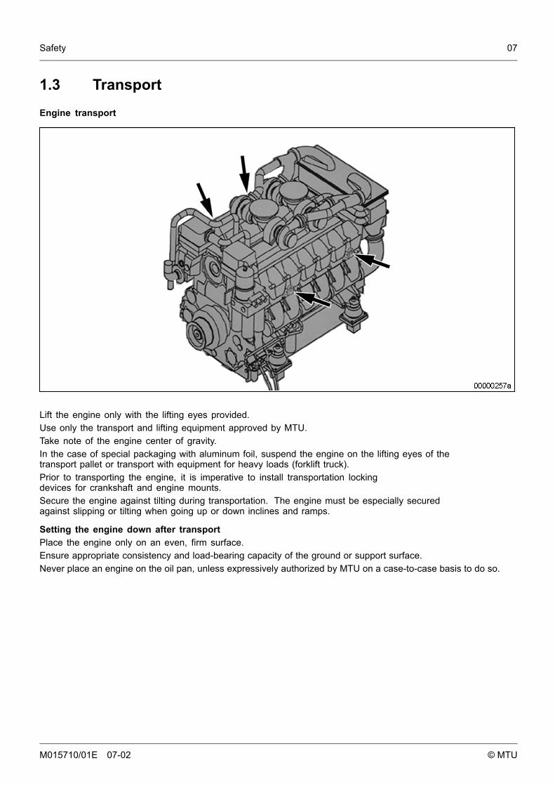
Engine transport
Lift the engine only with the lifting eyes provided.Use only the transport and lifting equipment approved by MTU.Take note of the engine center of gravity.In the case of special packaging with aluminum foil, suspend the engine on the lifting eyes of thetransport pallet or transport with equipment for heavy loads (forklift truck).Prior to transporting the engine, it is imperative to install transportation lockingdevices for crankshaft and engine mounts.Secure the engine against tilting during transportation. The engine must be especially securedagainst slipping or tilting when going up or down inclines and ramps.
Setting the engine down after transportPlace the engine only on an even, firm surface.Ensure appropriate consistency and load-bearing capacity of the ground or support surface.Never place an engine on the oil pan, unless expressively authorized by MTU on a case-to-case basis to do so.
M015710/01E 07-02 © MTU
08 Safety
1.4 Safety requirements when working on the engine
Safety precautions when putting the equipment into operationPrior to initial operation, the product must have been installed correctly and approved according to MTU specifications.Before putting the device or the system into operation, always ensure
• that all maintenance and repair work is completed• that all loose components have been removed from rotating parts• that nobody is standing in the danger zone of moving engine components.
Immediately after putting the device or system into operation, make sure that all control and displayinstruments as well as the signaling and alarm systems work properly.
Safety requirements for operatorsProcedures for cases of emergency must be practised regularly.The operator must be familiar with the controls and displays.The operator must know the consequences of each operation to be carried out.The operator must carry out the individual operations according to the documentation.During operation, the displays and monitoring units must be permanently observed with regard to presentoperating status, violation of limit values and warning or alarm messages.The following steps must be taken if a malfunction of the system is recognized or reported by the system:
• notify the supervisory personnel in charge• analyze the message• if required, carry out emergency operations e.g. emergency engine stop.
Engine operationWhen the engine is running, always wear ear protectors.Ensure that the engine room is well ventilated.Mop up any leaked or spilt fluids and lubricants immediately or soak up with a suitable bonding agent.Exhaust gases from combustion engines are poisonous. Inhalation of poisonous exhaust gases is a healthhazard. The exhaust pipework must be free of leaks and discharge the gases to atmosphere.During engine operation, do not touch battery terminals, generator terminals or cables.Inadequate protection of electrical components can lead to electric shocks and serious injuries.When the engine is running, never release coolant, oil, fuel, compressed-air or hydraulic lines.
Maintenance and repairStrict adherence to the maintenance and repair schedule is an essential safety factor.Never carry out maintenance and repair work with the engine running unless expressly instructed to do so.Lock-out/tag-out the engine to preclude undesired starting. Disconnect the battery when electrical starters are fitted.Close the main valve on the compressed-air system and vent the compressed air line when air starters are fitted. Postthe "Do Not Start" sign in the operating room or affix it to the controlling device! Persons not involved must keep clear.Never attempt to rectify faults or carry out repairs if you do not have the necessary experience or special toolsrequired. Have maintenance and repair work carried out by qualified and authorized personnel only.Use only proper, calibrated tools.Do not work on engines or components which are only held by lifting equipment or crane. Always support bysuitable means which conform with the applicable regulations before commencing maintenance or repair work.Before barring the engine, make sure that nobody is standing in the danger zone. After completingwork on the engine, check that all protective devices/safety guards have been installed and thatall tools and loose parts have been removed from the engine.Fluids emerging under high pressure can penetrate clothing and skin and may cause serious injury. Beforestarting work, relieve pressure in systems and H.P. lines which are to be opened.Never bend a fuel line and do not install bent lines. Keep fuel injection lines and connections clean.Always seal connections with caps or covers if a line is removed or opened.Take care not to damage fuel lines during maintenance and repair work. To tighten the connections when installingthe lines, use the correct tightening torque and ensure that all retainers and dampers are installed correctly.
M015710/01E 07-02 © MTU
Safety 09
Ensure that all fuel injection lines and pressurized oil lines have sufficient distance to othercomponents to avoid contact with them. Do not place fuel or oil lines near hot components,except when necessary for design reasons during installation.Elastomers (e.g. "Viton" sealing rings) are stable under normal operating conditions. The material decomposeswhen exposed to fire or temperatures exceeding 300 °C. Hydrogen fluoride vapors are released in thiscase. The resulting acid leads to serious burning if it contacts the skin. Do not touch elastomeric sealsif they have carbonized or resinous appearance. Wear protective gloves!Take care with hot fluids in lines, pipes and chambers ⇒ Risk of injury!Note cooling period for components which are heated for installation or removal ⇒ Risk of injury!Never touch hot parts of the compressor and exhaust system ⇒ Risk of burning!Take special care when removing ventilation or plugs from engine. In order to avoid discharge ofhighly pressurized liquids, hold a cloth over the screw or plug. It is even more dangerous if theengine has recently been shut down, as the liquids can still be hot.Take special care when draining hot fluids. ⇒ Risk of injury!When draining, collect fluids in a suitable container, mop up any spilt fluids or wipe orsoak them with a suitable bonding agent.When changing the engine oil or working on the fuel system, ensure that the engine room is adequately ventilated.When working high on the engine, always use suitable ladders and work platforms. Makesure components are placed on stable surfaces.In order to prevent back injuries when lifting heavy components adults, depending on age and sex,should only lift weights between max. 10 kg and 30 kg, therefore:
• Use lifting gear or seek assistance.• Ensure that all chains, hooks, slings, etc. are tested and authorized, are sufficiently strong and that
hooks are correctly positioned. Lifting eyes must not be unevenly loaded.Observe special cleanness when conducting maintenance and repair work on the engine plant. After completionof maintenance and repair work, make sure that no loose objects are in/on the engine plant.
Welding workNever carry out welding work on the engine or engine-mounted units.Never use the engine as a ground connection. This prevents the welding current passing throughthe engine resulting in burnt/scorched bearings, sliding surfaces and tooth flanks which maylead to bearing seizure and/or other material damage.Never route the welding lead over or near the wiring harnesses of MTU systems. The welding current may otherwiseinduce an interference voltage in the wiring harnesses which could conceivably damage the electrical system.The welding unit ground connection must not be more than 60 cm from the weld point.If components (e.g. exhaust manifold) are to be welded, they must be removed from the engine.It is not necessary to remove the connector and the connections when carrying out welding operationon MTU electronics if the master switch for power supply is switched from "ON" to "OFF" and the wireis disconnected from the negative and positive poles on the battery.
Hydraulic installation and removalOnly the hydraulic installation and removal equipment specified in the work schedule andin the assembly instructions must be used.The max. permissible push-on pressure specified for the equipment must not be exceeded.The H.P. lines for hydraulic installation and removal are tested with 3800 bar.Do not attempt to bend or apply force to lines.Before starting work, pay attention to the following:
• Vent the hydraulic installation/removal tool, the pumps and the lines at the relevant points for the system tobe used (e.g. open vent plugs, pump until bubble-free air emerges, close vent plugs).
• For hydraulic installation, screw on the tool with the piston retracted.• For hydraulic removal, screw on the tool with the piston extended.
For a hydraulic installation/removal tool with central expansion pressure supply, screw spindleinto shaft end until correct sealing is achieved.During hydraulic installation and removal, ensure that nobody is standing in the immediate vicinity of thecomponent to be installed/removed. As long as the system is under pressure, there is the risk that thecomponent to be installed/removed may be suddenly released from the pressure connection.
M015710/01E 07-02 © MTU
10 Safety
Before use, the tools must be checked at regular intervals (crack test).
Working on electrical/electronic assembliesAlways obtain the permission of the person in charge before commencing maintenance and repairwork or switching off any part of the electronic system required to do so.De-energize the appropriate areas prior to working on assemblies. Any measures requiring a powersupply are expressly defined as such at the appropriate place in the manual.Gases released from the battery are explosive. Avoid sparks and naked flames. Do not allow batteryacids to come in contact with skin or clothing. Wear protective goggles. Do not place tools on thebattery. Before connecting the cable to the battery, check battery polarity. Battery pole reversal may leadto injury through the sudden discharge of acid or bursting of the battery body.Do not damage wiring during removal work and when reinstalling wiring and ensure that during operation it isnot damaged by contact with sharp objects, by rubbing against other component or by a hot surface.Do not secure wiring to fluid-carrying lines.On completion of the maintenance and repair work, any cables which have become loosemust be correctly connected and secured.On completion of all repair work, the component and system must be subjected to a function check.Separate testing of the repaired component without system integration is insufficient.If wires are installed beside mechanical components and there is a risk of chafing, usecable clamps to properly support the wires.For this purpose, no cable binders must be used as, during maintenance and / or repair work,the binders can be removed but not installed a second time.Spare parts shall be properly stored prior to replacement, i.e. particularly protected against moisture. Defectiveelectronic components and assemblies must be suitably packed when dispatched for repair, i.e. particularlyprotected against moisture and impact and wrapped in antistatic foil if necessary.
Working with laser equipmentWhen working with laser equipment, always wear special laser-protection goggles.Laser equipment can generate extremely intensive, concentrated radiation by the effect of stimulated emissionin the range of visible light or in the infrared or ultraviolet spectral range. The photochemical, thermal andoptomechanical effects of the laser can cause damage. The main danger is irreparable damage to the eyes.Laser equipment must be fitted with the protective devices necessary for safeoperation according to type and application.For conducting light-beam procedures and measurement work, only the following laser devices must be used:
• Laser devices of classes 1, 2 or 3A,• Laser devices of class 3B, which have maximum output in the visible wavelength range (400 to 700 nm), a
maximum output of 5 mW, and in which the beam axis and surface are designed to prevent any risk to the eyes.
Operation of electrical equipmentWhen operating electrical equipment, certain components of this equipment are live.Noncompliance with the warning instructions given for this equipment may result inserious injury or damage to property.
M015710/01E 07-02 © MTU
Safety 11
1.5 Auxiliary materials, fire prevention and environmentalprotection
Fire preventionRectify any fuel or oil leaks immediately; even splashes of oil or fuel on hot components can cause fires -therefore always keep the engine in a clean condition. Do not leave cloths soaked with fluids and lubricantslying around on the engine. Do not store combustible materials near the engine.Do not carry out welding work on pipes and components carrying oil or fuel. Beforewelding, clean with a noncombustible fluid.When starting the engine with a foreign power source, connect the ground lead last and remove it first.To avoid sparks in the vicinity of the battery, connect the ground lead from the foreign power sourceto the ground lead of the engine or to the ground terminal of the starter.Always keep suitable fire-fighting equipment (fire extinguishers) at hand and familiarize yourself with their use.
NoiseNoise can lead to an increased risk of accident if acoustic signals, warning shouts orsounds indicating danger are drowned.At all workplaces with a sound pressure level over 85 dB (A), always wear ear protectors(protective wadding, plugs or capsules).
Environmental protectionDispose of used fluids, lubricants, materials and filters in accordance with local regulations.Manipulation of the injection control system can influence the engine performance and exhaust emissions.As a result, compliance with environmental regulations may no longer be guaranteed.Only fuels of the specified quality required to achieve emission limits must be used.In Germany, the VAwS (= regulations governing the use of materials that may affect water quality) is applicable,which means work must only be carried out by authorized specialist companies (MTU is such a company).
Auxiliary materialsUse only fluids and lubricants that have been tested and approved by MTU.Fluids and lubricants must be kept in suitable, properly designated containers. When using fluids, lubricants andother chemical substances, follow the safety instructions applicable to the product. Take care when handling hot,chilled or caustic materials. When using inflammable materials, avoid sparks, flames and do not smoke.
Lead• When working with lead or lead-containing pastes, avoid direct contact to the skin and do not inhale lead vapors.• Adopt suitable measures to avoid the formation of lead dust!• Switch on fume extraction system.• After coming into contact with lead or lead-containing materials, wash hands!
Acids and alkaline solutions• When working with acids and alkalis, wear protective goggles or face mask, gloves and protective clothing.• Immediately remove clothing wetted by acids and alkalis!• Rinse injuries with plenty of water!• Rinse eyes immediately with eyedrops or clean tap water.
Paints• When painting anywhere other than in spray booths equipped with extractors, ensure good
ventilation. Make sure that adjacent work areas are not affected.• No naked flames!• No smoking.• Observe fire prevention regulations!• Wear masks providing protection against paint and solvent fumes.
Liquid nitrogen• Store liquid nitrogen only in small quantities and always in regulation containers without fixed covers.• Do not bring liquid nitrogen in contact with the body (eyes, hands), as this causes frostbite and loss of tissue.• Wear protective clothing, including gloves, closed shoes and protective goggles!
M015710/01E 07-02 © MTU
12 Safety
• Ensure that the room is well ventilated. Nitrogen concentration exceeding 88% ofbreathing air leads to suffocation.
• Avoid all knocks and jars to the containers, fixtures or workpieces.
Compressed airCompressed air is air compressed at excess pressure and is stored in vessels from which it can be extracted.The pressure at which the air is kept can be read off at pressure gauges which must be connectedto the compressed air vessels and the compressed air lines.When working with compressed air, safety precautions must be constantly observed:
• Pay special attention to the pressure level in the compressed air network and pressure vessel!• Devices and equipment connected must either be designed for this pressure or, if the permitted
pressure for the connected elements is lower than the pressure required, a pressure reducingvalve and safety valve (set to permitted pressure) must form an intermediate connection. Hosecoupling and connections must be securely attached!
• Always wear protective goggles when blowing off tools or chips!• The snout of the air nozzle should be provided with a protective disc (e.g. rubber disc), which prevents
air-borne particles being deflected and thereby prevents injury to eyes.• First shut off compressed air lines before compressed air equipment is disconnected from the
supply line or before equipment or tools are exchanged!• Unauthorized use of compressed air, e.g. forcing flammable liquids (hazard class AI, AII
and B) out of containers, carries the risk of explosion!• Forcing compressed air into thin-walled containers (e.g. containers made of tin, plastic and glass)
for drying purposes or to check for leaks, results in a risk of shattering!• Do not use compressed air to clean contaminated clothing whilst it is being worn.
Used oilUsed oil may contain health-threatening combustion residues.Rub barrier cream into hands!Wash hands after contact with used oil.
M015710/01E 07-02 © MTU
Safety 13
1.6 Standards for warning notices in the publication
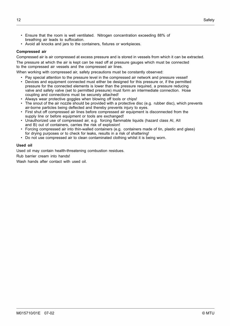
DANGER
In the event of immediate danger.Consequences: Death or serious injury.
• Preventive measures
WARNING
In the event of possibly dangerous situations.Consequences: Death or serious injury.
• Preventive measures
CAUTION
In the event of dangerous situations.Consequences: Slight injury or material damage.
• Preventive measures
Note: This Publication contains especially emphasized safety instructions in accordance with the Americanstandard ANSI Z535, which begin with one of the above signal words according to the degree of danger:
Warning notices1. Read and become acquainted with all cautions and symbols before operating or repairing this product.2. Pass on all safety instructions to your operating, maintenance, repair and transport personnel!
M015710/01E 07-02 © MTU
14 Safety
M015710/01E 07-02 © MTU
Product Summary 15
2 Product Summary
2.1 Engine Layout
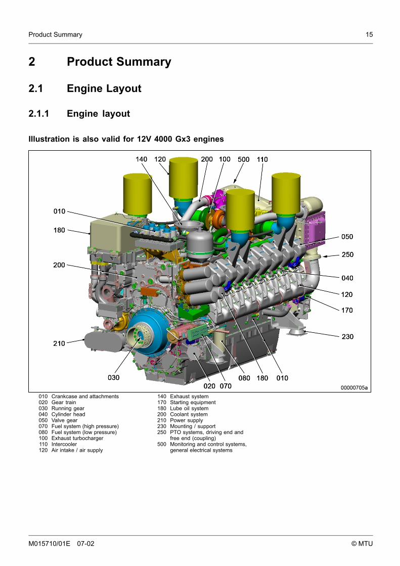
2.1.1 Engine layout
Illustration is also valid for 12V 4000 Gx3 engines
010 Crankcase and attachments020 Gear train030 Running gear040 Cylinder head050 Valve gear070 Fuel system (high pressure)080 Fuel system (low pressure)100 Exhaust turbocharger110 Intercooler120 Air intake / air supply
140 Exhaust system170 Starting equipment180 Lube oil system200 Coolant system210 Power supply230 Mounting / support250 PTO systems, driving end and
free end (coupling)500 Monitoring and control systems,
general electrical systems
M015710/01E 07-02 © MTU
16 Product Summary
Engine model designationKey to the engine model designations 12/16V 4000 Gx3
12/16 Number of cylinders
V Cylinder arrangement: Vee configuration
4000 Series
G Application
x Application segment (2, 4, 6, 8)
3 Design index
M015710/01E 07-02 © MTU

Product Summary 17
2.2 Engine Side and Cylinder Designations
2.2.1 Engine side and cylinder designationsEngine sides are always designated as viewed from the driving end (KS).The cylinders of the left engine side are designated "A" and those of the right side "B" (as per DIN ISO 1204).The cylinders of each bank are numbered consecutively, starting with No. 1 at the driving end.The numbering of engine components is also from the driving end, starting with No. 1.
1 KGS = Free end2 Right side
3 KS = Driving end4 Left side
M015710/01E 07-02 © MTU
18 Product Summary
2.3 Main Engine Dimensions
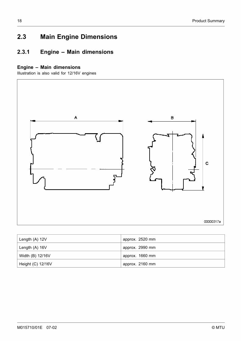
2.3.1 Engine – Main dimensions
Engine – Main dimensionsIllustration is also valid for 12/16V engines
Length (A) 12V approx. 2520 mm
Length (A) 16V approx. 2990 mm
Width (B) 12/16V approx. 1660 mm
Height (C) 12/16V approx. 2160 mm
M015710/01E 07-02 © MTU

Product Summary 19
2.4 Firing Order
2.4.1 Firing order
Firing order
12V A1-B5-A5-B3-A3-B6-A6-B2-A2-B4-A4-B1
16 V A1-A7-B4-B6-A4-B8-A2-A8-B3-B5-A3-A5-B2-A6-B1-B7
20V A1-B5-A8-B7-A5-B2-A7-B10-A2-B3-A10-B6-A3-B4-A6-B9-A4-B1-A9-B8
M015710/01E 07-02 © MTU
20 Product Summary
2.5 Final Compression Pressure
2.5.1 Final compression pressure
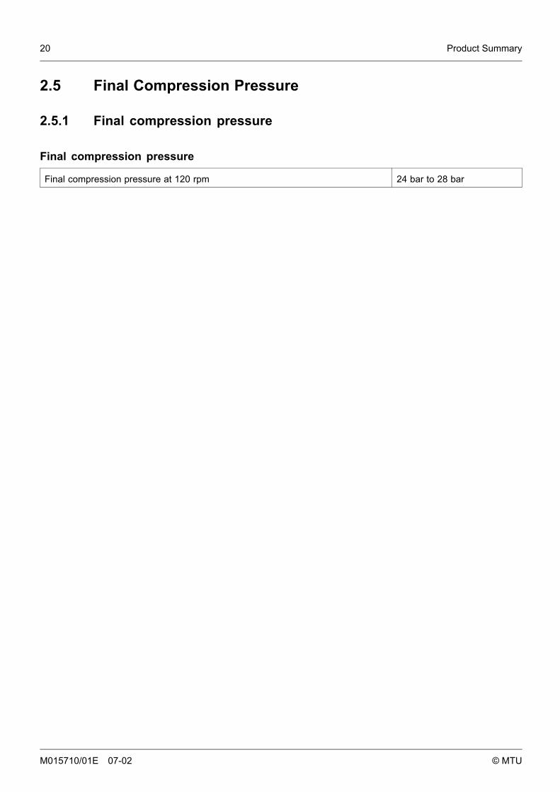
Final compression pressure
Final compression pressure at 120 rpm 24 bar to 28 bar
M015710/01E 07-02 © MTU
Product Summary 21
2.6 Technical Data
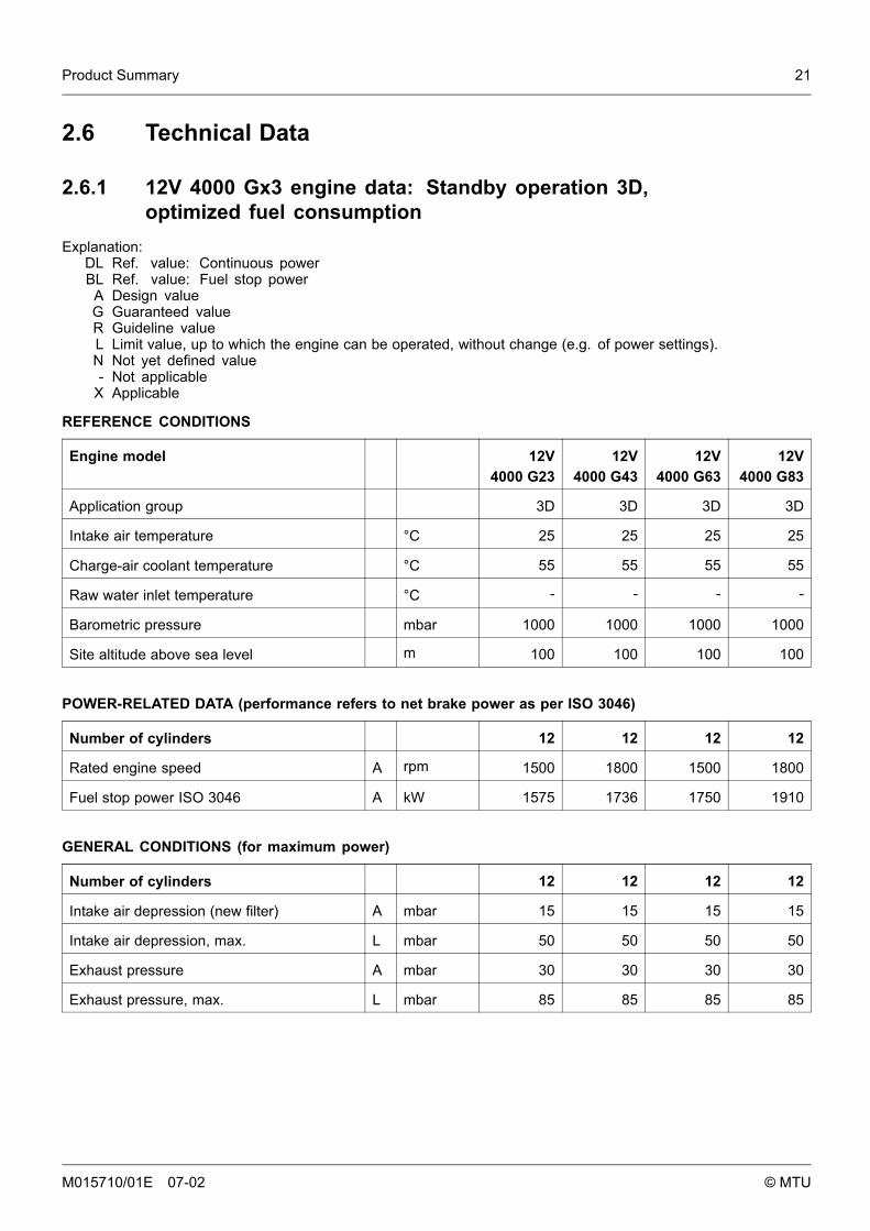
2.6.1 12V 4000 Gx3 engine data: Standby operation 3D,optimized fuel consumption
Explanation:DL Ref. value: Continuous powerBL Ref. value: Fuel stop power
A Design valueG Guaranteed valueR Guideline valueL Limit value, up to which the engine can be operated, without change (e.g. of power settings).N Not yet defined value- Not applicable
X Applicable
REFERENCE CONDITIONS
Engine model 12V4000 G23
12V4000 G43
12V4000 G63
12V4000 G83
Application group 3D 3D 3D 3D
Intake air temperature °C 25 25 25 25
Charge-air coolant temperature °C 55 55 55 55
Raw water inlet temperature °C - - - -
Barometric pressure mbar 1000 1000 1000 1000
Site altitude above sea level m 100 100 100 100
POWER-RELATED DATA (performance refers to net brake power as per ISO 3046)
Number of cylinders 12 12 12 12
Rated engine speed A rpm 1500 1800 1500 1800
Fuel stop power ISO 3046 A kW 1575 1736 1750 1910
GENERAL CONDITIONS (for maximum power)
Number of cylinders 12 12 12 12
Intake air depression (new filter) A mbar 15 15 15 15
Intake air depression, max. L mbar 50 50 50 50
Exhaust pressure A mbar 30 30 30 30
Exhaust pressure, max. L mbar 85 85 85 85
M015710/01E 07-02 © MTU
22 Product Summary
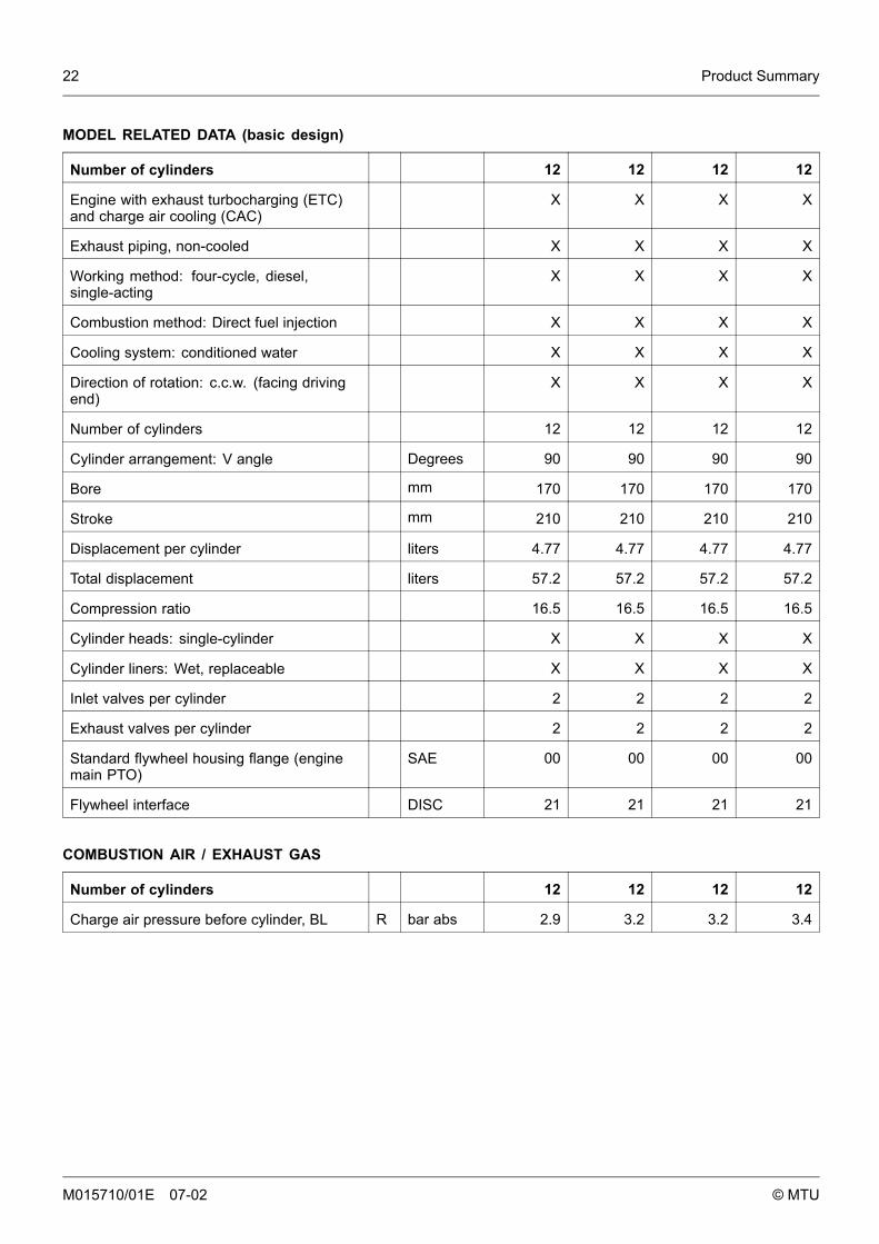
MODEL RELATED DATA (basic design)
Number of cylinders 12 12 12 12
Engine with exhaust turbocharging (ETC)and charge air cooling (CAC)
X X X X
Exhaust piping, non-cooled X X X X
Working method: four-cycle, diesel,single-acting
X X X X
Combustion method: Direct fuel injection X X X X
Cooling system: conditioned water X X X X
Direction of rotation: c.c.w. (facing drivingend)
X X X X
Number of cylinders 12 12 12 12
Cylinder arrangement: V angle Degrees 90 90 90 90
Bore mm 170 170 170 170
Stroke mm 210 210 210 210
Displacement per cylinder liters 4.77 4.77 4.77 4.77
Total displacement liters 57.2 57.2 57.2 57.2
Compression ratio 16.5 16.5 16.5 16.5
Cylinder heads: single-cylinder X X X X
Cylinder liners: Wet, replaceable X X X X
Inlet valves per cylinder 2 2 2 2
Exhaust valves per cylinder 2 2 2 2
Standard flywheel housing flange (enginemain PTO)
SAE 00 00 00 00
Flywheel interface DISC 21 21 21 21
COMBUSTION AIR / EXHAUST GAS
Number of cylinders 12 12 12 12
Charge air pressure before cylinder, BL R bar abs 2.9 3.2 3.2 3.4
M015710/01E 07-02 © MTU
Product Summary 23
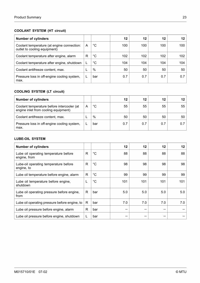
COOLANT SYSTEM (HT circuit)
Number of cylinders 12 12 12 12
Coolant temperature (at engine connection:outlet to cooling equipment)
A °C 100 100 100 100
Coolant temperature after engine, alarm R °C 102 102 102 102
Coolant temperature after engine, shutdown L °C 104 104 104 104
Coolant antifreeze content, max. L % 50 50 50 50
Pressure loss in off-engine cooling system,max.
L bar 0.7 0.7 0.7 0.7
COOLING SYSTEM (LT circuit)
Number of cylinders 12 12 12 12
Coolant temperature before intercooler (atengine inlet from cooling equipment)
A °C 55 55 55 55
Coolant antifreeze content, max. L % 50 50 50 50
Pressure loss in off-engine cooling system,max.
L bar 0.7 0.7 0.7 0.7
LUBE-OIL SYSTEM
Number of cylinders 12 12 12 12
Lube oil operating temperature beforeengine, from
R °C 88 88 88 88
Lube-oil operating temperature beforeengine, to
R °C 98 98 98 98
Lube oil temperature before engine, alarm R °C 99 99 99 99
Lube oil temperature before engine,shutdown
L °C 101 101 101 101
Lube oil operating pressure before engine,from
R bar 5.0 5.0 5.0 5.0
Lube oil operating pressure before engine, to R bar 7.0 7.0 7.0 7.0
Lube oil pressure before engine, alarm R bar -- -- -- --
Lube oil pressure before engine, shutdown L bar -- -- -- --
M015710/01E 07-02 © MTU
24 Product Summary
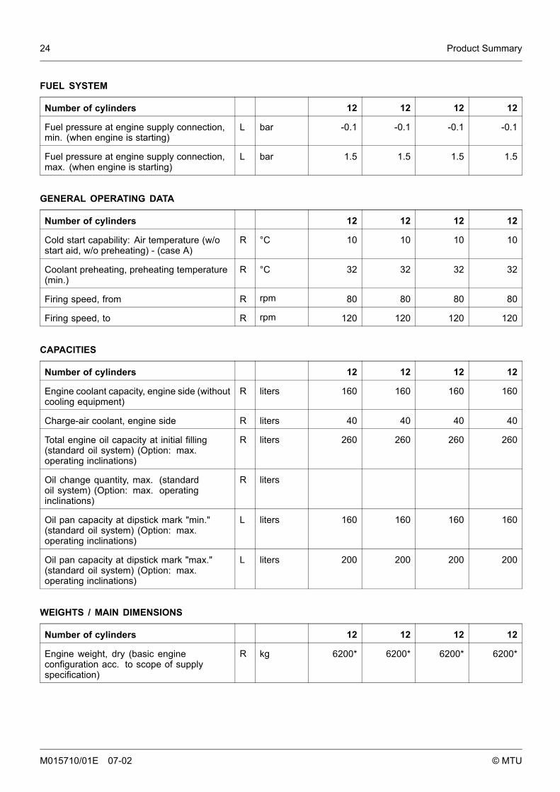
FUEL SYSTEM
Number of cylinders 12 12 12 12
Fuel pressure at engine supply connection,min. (when engine is starting)
L bar -0.1 -0.1 -0.1 -0.1
Fuel pressure at engine supply connection,max. (when engine is starting)
L bar 1.5 1.5 1.5 1.5
GENERAL OPERATING DATA
Number of cylinders 12 12 12 12
Cold start capability: Air temperature (w/ostart aid, w/o preheating) - (case A)
R °C 10 10 10 10
Coolant preheating, preheating temperature(min.)
R °C 32 32 32 32
Firing speed, from R rpm 80 80 80 80
Firing speed, to R rpm 120 120 120 120
CAPACITIES
Number of cylinders 12 12 12 12
Engine coolant capacity, engine side (withoutcooling equipment)
R liters 160 160 160 160
Charge-air coolant, engine side R liters 40 40 40 40
Total engine oil capacity at initial filling(standard oil system) (Option: max.operating inclinations)
R liters 260 260 260 260
Oil change quantity, max. (standardoil system) (Option: max. operatinginclinations)
R liters
Oil pan capacity at dipstick mark "min."(standard oil system) (Option: max.operating inclinations)
L liters 160 160 160 160
Oil pan capacity at dipstick mark "max."(standard oil system) (Option: max.operating inclinations)
L liters 200 200 200 200
WEIGHTS / MAIN DIMENSIONS
Number of cylinders 12 12 12 12
Engine weight, dry (basic engineconfiguration acc. to scope of supplyspecification)
R kg 6200* 6200* 6200* 6200*
M015710/01E 07-02 © MTU
Product Summary 25
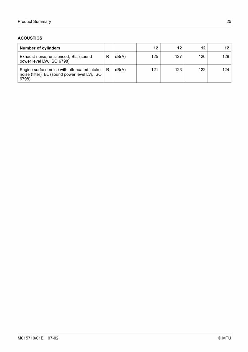
ACOUSTICS
Number of cylinders 12 12 12 12
Exhaust noise, unsilenced, BL, (soundpower level LW, ISO 6798)
R dB(A) 125 127 126 129
Engine surface noise with attenuated intakenoise (filter), BL (sound power level LW, ISO6798)
R dB(A) 121 123 122 124
M015710/01E 07-02 © MTU
26 Product Summary
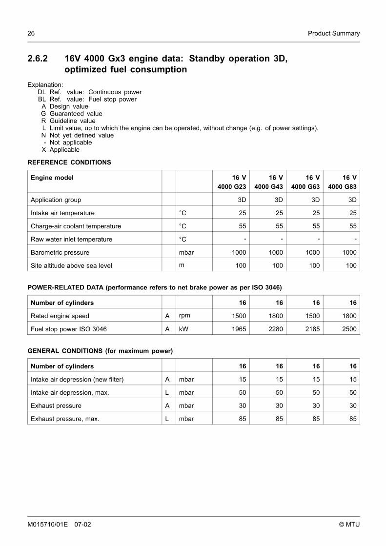
2.6.2 16V 4000 Gx3 engine data: Standby operation 3D,optimized fuel consumption
Explanation:DL Ref. value: Continuous powerBL Ref. value: Fuel stop power
A Design valueG Guaranteed valueR Guideline valueL Limit value, up to which the engine can be operated, without change (e.g. of power settings).N Not yet defined value- Not applicable
X Applicable
REFERENCE CONDITIONS
Engine model 16 V4000 G23
16 V4000 G43
16 V4000 G63
16 V4000 G83
Application group 3D 3D 3D 3D
Intake air temperature °C 25 25 25 25
Charge-air coolant temperature °C 55 55 55 55
Raw water inlet temperature °C - - - -
Barometric pressure mbar 1000 1000 1000 1000
Site altitude above sea level m 100 100 100 100
POWER-RELATED DATA (performance refers to net brake power as per ISO 3046)
Number of cylinders 16 16 16 16
Rated engine speed A rpm 1500 1800 1500 1800
Fuel stop power ISO 3046 A kW 1965 2280 2185 2500
GENERAL CONDITIONS (for maximum power)
Number of cylinders 16 16 16 16
Intake air depression (new filter) A mbar 15 15 15 15
Intake air depression, max. L mbar 50 50 50 50
Exhaust pressure A mbar 30 30 30 30
Exhaust pressure, max. L mbar 85 85 85 85
M015710/01E 07-02 © MTU

Product Summary 27
MODEL RELATED DATA (basic design)
Number of cylinders 16 16 16 16
Engine with exhaust turbocharging (ETC)and charge air cooling (CAC)
X X X X
Exhaust piping, non-cooled X X X X
Working method: four-cycle, diesel,single-acting
X X X X
Combustion method: Direct fuel injection X X X X
Cooling system: conditioned water X X X X
Direction of rotation: c.c.w. (facing drivingend)
X X X X
Number of cylinders 16 16 16 16
Cylinder arrangement: V angle Degrees 90 90 90 90
Bore mm 170 170 170 170
Stroke mm 210 210 210 210
Displacement per cylinder liters 4.77 4.77 4.77 4.77
Total displacement liters 76.3 76.3 76.3 76.3
Compression ratio 16.5 16.5 16.5 16.5
Cylinder heads: single-cylinder X X X X
Cylinder liners: Wet, replaceable X X X X
Inlet valves per cylinder 2 2 2 2
Exhaust valves per cylinder 2 2 2 2
Standard flywheel housing flange (enginemain PTO)
SAE 00 00 00 00
Flywheel interface DISC 21 21 21 21
COMBUSTION AIR / EXHAUST GAS
Number of cylinders 16 16 16 16
Charge air pressure before cylinder, BL R bar abs 2.8 3.1 3.1 3.3
M015710/01E 07-02 © MTU

28 Product Summary
COOLANT SYSTEM (HT circuit)
Number of cylinders 16 16 16 16
Coolant temperature (at engine connection:outlet to cooling equipment)
A °C 100 100 100 100
Coolant temperature after engine, alarm R °C 102 102 102 102
Coolant temperature after engine, shutdown L °C 104 104 104 104
Coolant antifreeze content, max. L % 50 50 50 50
Pressure loss in off-engine cooling system,max.
L bar 0.7 0.7 0.7 0.7
COOLING SYSTEM (LT circuit)
Number of cylinders 16 16 16 16
Coolant temperature before intercooler (atengine inlet from cooling equipment)
A °C 55 55 55 55
Coolant antifreeze content, max. L % 50 50 50 50
Pressure loss in off-engine cooling system,max.
L bar 0.7 0.7 0.7 0.7
LUBE-OIL SYSTEM
Number of cylinders 16 16 16 16
Lube oil operating temperature beforeengine, from
R °C 89 88 88 88
Lube-oil operating temperature beforeengine, to
R °C 95 95 94 94
Lube oil temperature before engine, alarm R °C 97 97 97 97
Lube oil temperature before engine,shutdown
L °C 99 99 99 99
Lube oil operating pressure before engine,from
R bar 4.2 4.7 4.2 4.7
Lube oil operating pressure before engine, to R bar 5.5 6.5 5.5 6.5
Lube oil pressure before engine, alarm R bar -- -- -- --
Lube oil pressure before engine, shutdown L bar -- -- -- --
M015710/01E 07-02 © MTU

Product Summary 29
FUEL SYSTEM
Number of cylinders 16 16 16 16
Fuel pressure at engine supply connection,min. (when engine is starting)
L bar -0.1 -0.1 -0.1 -0.1
Fuel pressure at engine supply connection,max. (when engine is starting)
L bar 1.5 1.5 1.5 1.5
GENERAL OPERATING DATA
Number of cylinders 16 16 16 16
Cold start capability: Air temperature (w/ostart aid, w/o preheating) - (case A)
R °C 10 10 10 10
Coolant preheating, preheating temperature(min.)
R °C 32 32 32 32
Firing speed, from R rpm 80 80 80 80
Firing speed, to R rpm 120 120 120 120
CAPACITIES
Number of cylinders 16 16 16 16
Engine coolant capacity, engine side (withoutcooling equipment)
R liters 260 260 260 260
Charge-air coolant, engine side R liters 50 50 50 50
Total engine oil capacity at initial filling(standard oil system) (Option: max.operating inclinations)
R liters 300 300 300 300
Oil change quantity, max. (standardoil system) (Option: max. operatinginclinations)
R liters 240 240 240 240
Oil pan capacity at dipstick mark "min."(standard oil system) (Option: max.operating inclinations)
L liters 210 210 210 210
Oil pan capacity at dipstick mark "max."(standard oil system) (Option: max.operating inclinations)
L liters 240 240 240 240
WEIGHTS / MAIN DIMENSIONS
Number of cylinders 16 16 16 16
Engine weight, dry (basic engineconfiguration acc. to scope of supplyspecification)
R kg 7700 7700 7700 7700
M015710/01E 07-02 © MTU

30 Product Summary
ACOUSTICS
Number of cylinders 16 16 16 16
Exhaust noise, unsilenced, BL, (soundpower level LW, ISO 6798)
R dB(A) 126 129 128 130
Engine surface noise with attenuated intakenoise (filter), BL (sound power level LW, ISO6798)
R dB(A) 128 125 125 126
M015710/01E 07-02 © MTU

Product Summary 31
2.6.3 Engine data 12/16V 4000 Gx3: Standby operation 3D, optimizedexhaust emissions (EPA stage 2)
Explanation:DL Ref. value: Continuous powerBL Ref. value: Fuel stop power
A Design valueG Guaranteed valueR Guideline valueL Limit value, up to which the engine can be operated, without change (e.g. of power settings).N Not yet defined value- Not applicable
X Applicable
REFERENCE CONDITIONS
Engine model 12V4000 G43
12V4000 G83
16 V4000 G43
16 V4000 G83
Application group 3D 3D 3D 3D
Intake air temperature °C 25 25 25 25
Charge-air coolant temperature °C 45 45 45 45
Raw water inlet temperature °C - - - -
Barometric pressure mbar 1000 1000 1000 1000
Site altitude above sea level m 100 100 100 100
POWER-RELATED DATA (performance refers to net brake power as per ISO 3046)
Number of cylinders 12 12 16 16
Rated engine speed A rpm 1800 1800 1800 1800
Fuel stop power ISO 3046 A kW 1736 1910 2280 2500
GENERAL CONDITIONS (for maximum power)
Number of cylinders 12 12 16 16
Intake air depression (new filter) A mbar 15 15 15 15
Intake air depression, max. L mbar 50 50 50 50
Exhaust pressure A mbar 30 30 30 30
Exhaust pressure, max. L mbar 85 85 85 85
M015710/01E 07-02 © MTU

32 Product Summary
MODEL RELATED DATA (basic design)
Number of cylinders 12 12 16 16
Engine with exhaust turbocharging (ETC)and charge air cooling (CAC)
X X X X
Exhaust piping, non-cooled X X X X
Working method: four-cycle, diesel,single-acting
X X X X
Combustion method: Direct fuel injection X X X X
Cooling system: conditioned water X X X X
Direction of rotation: c.c.w. (facing drivingend)
X X X X
Number of cylinders 12 12 16 16
Cylinder arrangement: V angle Degrees 90 90 90 90
Bore mm 170 170 170 170
Stroke mm 210 210 210 210
Displacement per cylinder liters 4.77 4.77 4.77 4,77
Total displacement liters 57.2 57.2 76,3 76.3
Compression ratio 16.5 16.5 16.5 16.5
Cylinder heads: single-cylinder X X X X
Cylinder liners: Wet, replaceable X X X X
Inlet valves per cylinder 2 2 2 2
Exhaust valves per cylinder 2 2 2 2
Standard flywheel housing flange (enginemain PTO)
SAE 00 00 00 00
Flywheel interface DISC 21 21 21 21
COMBUSTION AIR / EXHAUST GAS
Number of cylinders 12 12 16 16
Charge air pressure before cylinder, BL R bar abs 3.2 3.3 3.2 3.3
M015710/01E 07-02 © MTU

Product Summary 33
COOLANT SYSTEM (HT circuit)
Number of cylinders 12 12 16 16
Coolant temperature (at engine connection:outlet to cooling equipment)
A °C 100 100 100 100
Coolant temperature after engine, alarm R °C 102 102 102 102
Coolant temperature after engine, shutdown L °C 104 104 104 104
Coolant antifreeze content, max. L % 50 50 50 50
Pressure loss in off-engine cooling system,max.
L bar 0.7 0.7 0.7 0.7
COOLING SYSTEM (LT circuit)
Number of cylinders 12 12 16 16
Coolant temperature before intercooler (atengine inlet from cooling equipment)
A °C 45 45 45 45
Coolant antifreeze content, max. L % 50 50 50 50
Pressure loss in off-engine cooling system,max.
L bar 0.7 0.7 0.7 0.7
LUBE-OIL SYSTEM
Number of cylinders 12 12 16 16
Lube oil operating temperature beforeengine, from
R °C 88 88 88 88
Lube-oil operating temperature beforeengine, to
R °C 98 98 94 94
Lube oil temperature before engine, alarm R °C 99 99 97 97
Lube oil temperature before engine,shutdown
L °C 101 101 99 99
Lube oil operating pressure before engine,from
R bar 5.0 5.0 4.7 4.7
Lube oil operating pressure before engine, to R bar 7.0 7.0 6.5 6.5
Lube oil pressure before engine, alarm R bar -- -- -- --
Lube oil pressure before engine, shutdown L bar -- -- -- --
M015710/01E 07-02 © MTU
34 Product Summary
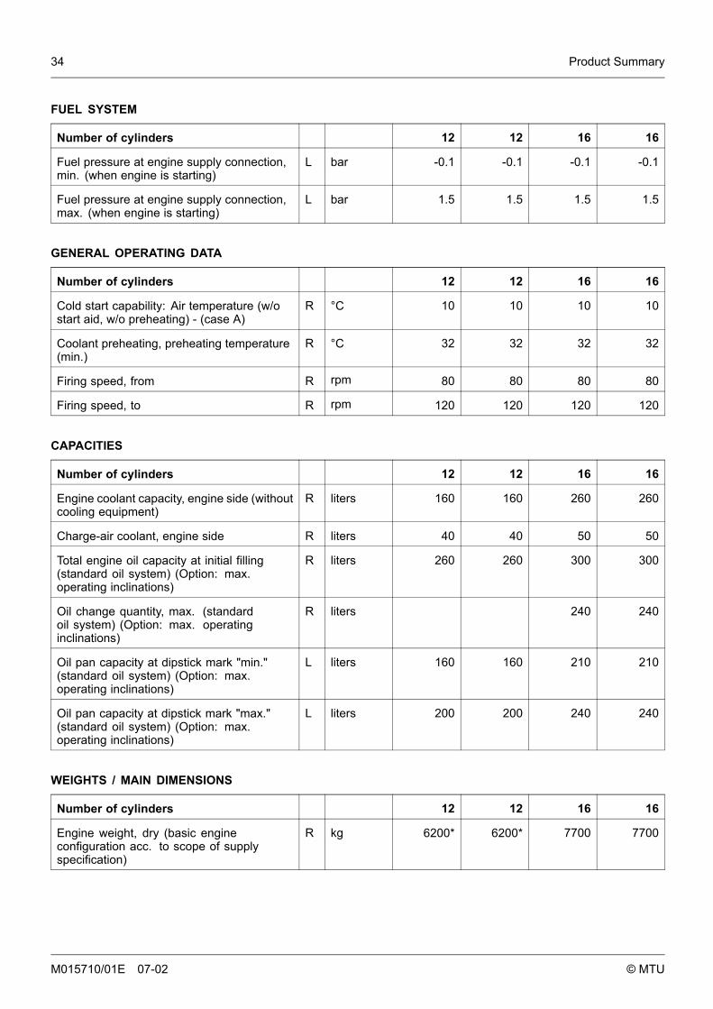
FUEL SYSTEM
Number of cylinders 12 12 16 16
Fuel pressure at engine supply connection,min. (when engine is starting)
L bar -0.1 -0.1 -0.1 -0.1
Fuel pressure at engine supply connection,max. (when engine is starting)
L bar 1.5 1.5 1.5 1.5
GENERAL OPERATING DATA
Number of cylinders 12 12 16 16
Cold start capability: Air temperature (w/ostart aid, w/o preheating) - (case A)
R °C 10 10 10 10
Coolant preheating, preheating temperature(min.)
R °C 32 32 32 32
Firing speed, from R rpm 80 80 80 80
Firing speed, to R rpm 120 120 120 120
CAPACITIES
Number of cylinders 12 12 16 16
Engine coolant capacity, engine side (withoutcooling equipment)
R liters 160 160 260 260
Charge-air coolant, engine side R liters 40 40 50 50
Total engine oil capacity at initial filling(standard oil system) (Option: max.operating inclinations)
R liters 260 260 300 300
Oil change quantity, max. (standardoil system) (Option: max. operatinginclinations)
R liters 240 240
Oil pan capacity at dipstick mark "min."(standard oil system) (Option: max.operating inclinations)
L liters 160 160 210 210
Oil pan capacity at dipstick mark "max."(standard oil system) (Option: max.operating inclinations)
L liters 200 200 240 240
WEIGHTS / MAIN DIMENSIONS
Number of cylinders 12 12 16 16
Engine weight, dry (basic engineconfiguration acc. to scope of supplyspecification)
R kg 6200* 6200* 7700 7700
M015710/01E 07-02 © MTU

Product Summary 35
ACOUSTICS
Number of cylinders 12 12 16 16
Exhaust noise, unsilenced, BL, (soundpower level LW, ISO 6798)
R dB(A) 127 129 129 130
Engine surface noise with attenuated intakenoise (filter), BL (sound power level LW, ISO6798)
R dB(A) 123 124 125 126
M015710/01E 07-02 © MTU
36 Product Summary
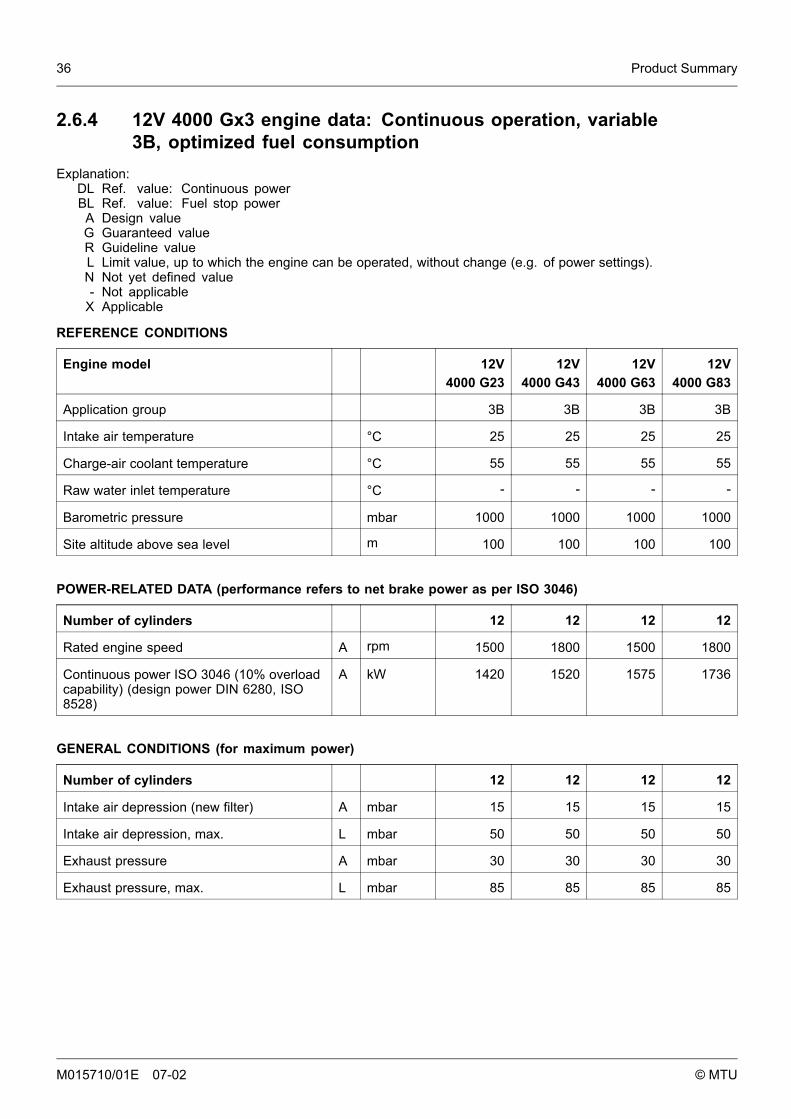
2.6.4 12V 4000 Gx3 engine data: Continuous operation, variable3B, optimized fuel consumption
Explanation:DL Ref. value: Continuous powerBL Ref. value: Fuel stop power
A Design valueG Guaranteed valueR Guideline valueL Limit value, up to which the engine can be operated, without change (e.g. of power settings).N Not yet defined value- Not applicable
X Applicable
REFERENCE CONDITIONS
Engine model 12V4000 G23
12V4000 G43
12V4000 G63
12V4000 G83
Application group 3B 3B 3B 3B
Intake air temperature °C 25 25 25 25
Charge-air coolant temperature °C 55 55 55 55
Raw water inlet temperature °C - - - -
Barometric pressure mbar 1000 1000 1000 1000
Site altitude above sea level m 100 100 100 100
POWER-RELATED DATA (performance refers to net brake power as per ISO 3046)
Number of cylinders 12 12 12 12
Rated engine speed A rpm 1500 1800 1500 1800
Continuous power ISO 3046 (10% overloadcapability) (design power DIN 6280, ISO8528)
A kW 1420 1520 1575 1736
GENERAL CONDITIONS (for maximum power)
Number of cylinders 12 12 12 12
Intake air depression (new filter) A mbar 15 15 15 15
Intake air depression, max. L mbar 50 50 50 50
Exhaust pressure A mbar 30 30 30 30
Exhaust pressure, max. L mbar 85 85 85 85
M015710/01E 07-02 © MTU
Product Summary 37
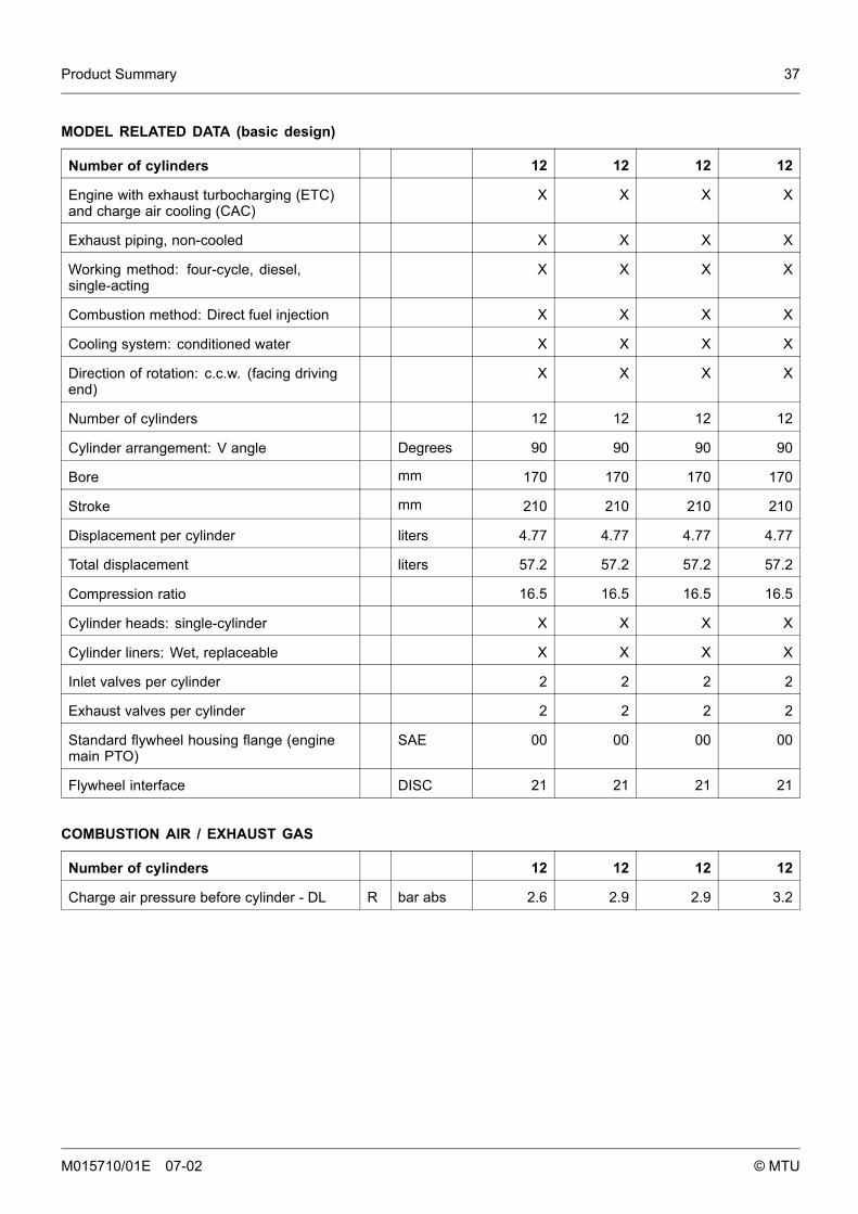
MODEL RELATED DATA (basic design)
Number of cylinders 12 12 12 12
Engine with exhaust turbocharging (ETC)and charge air cooling (CAC)
X X X X
Exhaust piping, non-cooled X X X X
Working method: four-cycle, diesel,single-acting
X X X X
Combustion method: Direct fuel injection X X X X
Cooling system: conditioned water X X X X
Direction of rotation: c.c.w. (facing drivingend)
X X X X
Number of cylinders 12 12 12 12
Cylinder arrangement: V angle Degrees 90 90 90 90
Bore mm 170 170 170 170
Stroke mm 210 210 210 210
Displacement per cylinder liters 4.77 4.77 4.77 4.77
Total displacement liters 57.2 57.2 57.2 57.2
Compression ratio 16.5 16.5 16.5 16.5
Cylinder heads: single-cylinder X X X X
Cylinder liners: Wet, replaceable X X X X
Inlet valves per cylinder 2 2 2 2
Exhaust valves per cylinder 2 2 2 2
Standard flywheel housing flange (enginemain PTO)
SAE 00 00 00 00
Flywheel interface DISC 21 21 21 21
COMBUSTION AIR / EXHAUST GAS
Number of cylinders 12 12 12 12
Charge air pressure before cylinder - DL R bar abs 2.6 2.9 2.9 3.2
M015710/01E 07-02 © MTU
38 Product Summary
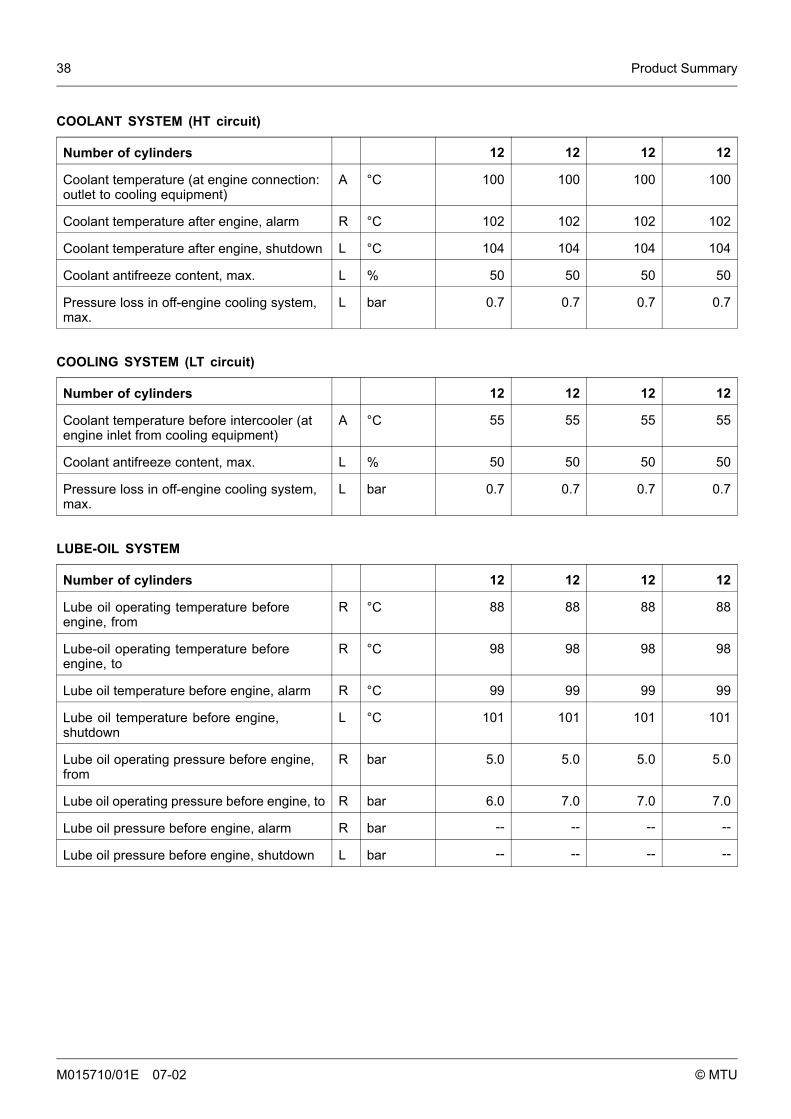
COOLANT SYSTEM (HT circuit)
Number of cylinders 12 12 12 12
Coolant temperature (at engine connection:outlet to cooling equipment)
A °C 100 100 100 100
Coolant temperature after engine, alarm R °C 102 102 102 102
Coolant temperature after engine, shutdown L °C 104 104 104 104
Coolant antifreeze content, max. L % 50 50 50 50
Pressure loss in off-engine cooling system,max.
L bar 0.7 0.7 0.7 0.7
COOLING SYSTEM (LT circuit)
Number of cylinders 12 12 12 12
Coolant temperature before intercooler (atengine inlet from cooling equipment)
A °C 55 55 55 55
Coolant antifreeze content, max. L % 50 50 50 50
Pressure loss in off-engine cooling system,max.
L bar 0.7 0.7 0.7 0.7
LUBE-OIL SYSTEM
Number of cylinders 12 12 12 12
Lube oil operating temperature beforeengine, from
R °C 88 88 88 88
Lube-oil operating temperature beforeengine, to
R °C 98 98 98 98
Lube oil temperature before engine, alarm R °C 99 99 99 99
Lube oil temperature before engine,shutdown
L °C 101 101 101 101
Lube oil operating pressure before engine,from
R bar 5.0 5.0 5.0 5.0
Lube oil operating pressure before engine, to R bar 6.0 7.0 7.0 7.0
Lube oil pressure before engine, alarm R bar -- -- -- --
Lube oil pressure before engine, shutdown L bar -- -- -- --
M015710/01E 07-02 © MTU
Product Summary 39
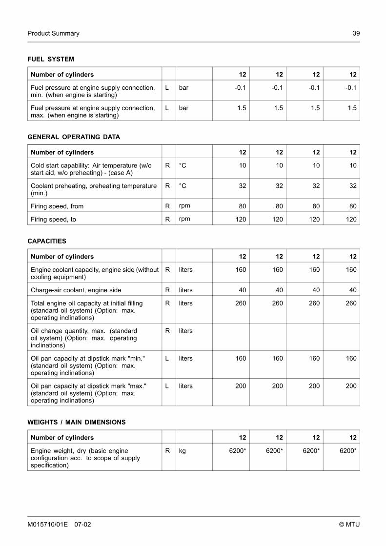
FUEL SYSTEM
Number of cylinders 12 12 12 12
Fuel pressure at engine supply connection,min. (when engine is starting)
L bar -0.1 -0.1 -0.1 -0.1
Fuel pressure at engine supply connection,max. (when engine is starting)
L bar 1.5 1.5 1.5 1.5
GENERAL OPERATING DATA
Number of cylinders 12 12 12 12
Cold start capability: Air temperature (w/ostart aid, w/o preheating) - (case A)
R °C 10 10 10 10
Coolant preheating, preheating temperature(min.)
R °C 32 32 32 32
Firing speed, from R rpm 80 80 80 80
Firing speed, to R rpm 120 120 120 120
CAPACITIES
Number of cylinders 12 12 12 12
Engine coolant capacity, engine side (withoutcooling equipment)
R liters 160 160 160 160
Charge-air coolant, engine side R liters 40 40 40 40
Total engine oil capacity at initial filling(standard oil system) (Option: max.operating inclinations)
R liters 260 260 260 260
Oil change quantity, max. (standardoil system) (Option: max. operatinginclinations)
R liters
Oil pan capacity at dipstick mark "min."(standard oil system) (Option: max.operating inclinations)
L liters 160 160 160 160
Oil pan capacity at dipstick mark "max."(standard oil system) (Option: max.operating inclinations)
L liters 200 200 200 200
WEIGHTS / MAIN DIMENSIONS
Number of cylinders 12 12 12 12
Engine weight, dry (basic engineconfiguration acc. to scope of supplyspecification)
R kg 6200* 6200* 6200* 6200*
M015710/01E 07-02 © MTU
40 Product Summary
ACOUSTICS
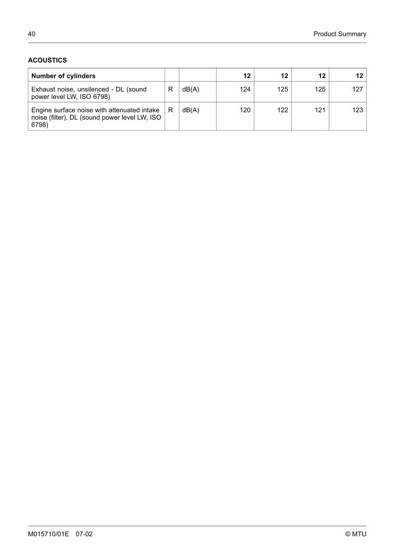
Number of cylinders 12 12 12 12
Exhaust noise, unsilenced - DL (soundpower level LW, ISO 6798)
R dB(A) 124 125 125 127
Engine surface noise with attenuated intakenoise (filter), DL (sound power level LW, ISO6798)
R dB(A) 120 122 121 123
M015710/01E 07-02 © MTU

Product Summary 41
2.6.5 16V 4000 Gx3 engine data: Continuous operation, variable3B, optimized fuel consumption
Explanation:DL Ref. value: Continuous powerBL Ref. value: Fuel stop power
A Design valueG Guaranteed valueR Guideline valueL Limit value, up to which the engine can be operated, without change (e.g. of power settings).N Not yet defined value- Not applicable
X Applicable
REFERENCE CONDITIONS
Engine model 16 V4000 G23
16 V4000 G43
16 V4000 G63
16 V4000 G83
Application group 3B 3B 3B 3B
Intake air temperature °C 25 25 25 25
Charge-air coolant temperature °C 55 55 55 55
Raw water inlet temperature °C - - - -
Barometric pressure mbar 1000 1000 1000 1000
Site altitude above sea level m 100 100 100 100
POWER-RELATED DATA (performance refers to net brake power as per ISO 3046)
Number of cylinders 16 16 16 16
Rated engine speed A rpm 1500 1800 1500 1800
Continuous power ISO 3046 (10% overloadcapability) (design power DIN 6280, ISO8528)
A kW 1798 2020 1965 2280
GENERAL CONDITIONS (for maximum power)
Number of cylinders 16 16 16 16
Intake air depression (new filter) A mbar 15 15 15 15
Intake air depression, max. L mbar 50 50 50 50
Exhaust pressure A mbar 30 30 30 30
Exhaust pressure, max. L mbar 85 85 85 85
M015710/01E 07-02 © MTU

42 Product Summary
MODEL RELATED DATA (basic design)
Number of cylinders 16 16 16 16
Engine with exhaust turbocharging (ETC)and charge air cooling (CAC)
X X X X
Exhaust piping, non-cooled X X X X
Working method: four-cycle, diesel,single-acting
X X X X
Combustion method: Direct fuel injection X X X X
Cooling system: conditioned water X X X X
Direction of rotation: c.c.w. (facing drivingend)
X X X X
Number of cylinders 16 16 16 16
Cylinder arrangement: V angle Degrees 90 90 90 90
Bore mm 170 170 170 170
Stroke mm 210 210 210 210
Displacement per cylinder liters 4.77 4.77 4.77 4.77
Total displacement liters 76.3 76.3 76.3 76.3
Compression ratio 16.5 16.5 16.5 16.5
Cylinder heads: single-cylinder X X X X
Cylinder liners: Wet, replaceable X X X X
Inlet valves per cylinder 2 2 2 2
Exhaust valves per cylinder 2 2 2 2
Standard flywheel housing flange (enginemain PTO)
SAE 00 00 00 00
Flywheel interface DISC 21 21 21 21
COMBUSTION AIR / EXHAUST GAS
Number of cylinders 16 16 16 16
Charge air pressure before cylinder - DL R bar abs 2.6 2.9 2.8 3.1
M015710/01E 07-02 © MTU

Product Summary 43
COOLANT SYSTEM (HT circuit)
Number of cylinders 16 16 16 16
Coolant temperature (at engine connection:outlet to cooling equipment)
A °C 100 100 100 100
Coolant temperature after engine, alarm R °C 102 102 102 102
Coolant temperature after engine, shutdown L °C 104 104 104 104
Coolant antifreeze content, max. L % 50 50 50 50
Pressure loss in off-engine cooling system,max.
L bar 0.7 0.7 0.7 0.7
COOLING SYSTEM (LT circuit)
Number of cylinders 16 16 16 16
Coolant temperature before intercooler (atengine inlet from cooling equipment)
A °C 55 55 55 55
Coolant antifreeze content, max. L % 50 50 50 50
Pressure loss in off-engine cooling system,max.
L bar 0.7 0.7 0.7 0.7
LUBE-OIL SYSTEM
Number of cylinders 16 16 16 16
Lube oil operating temperature beforeengine, from
R °C 89 90 89 88
Lube-oil operating temperature beforeengine, to
R °C 95 96 95 95
Lube oil temperature before engine, alarm R °C 97 97 97 97
Lube oil temperature before engine,shutdown
L °C 99 99 99 99
Lube oil operating pressure before engine,from
R bar 4.2 4.7 4.2 4.7
Lube oil operating pressure before engine, to R bar 5.5 6.5 5.5 6.5
Lube oil pressure before engine, alarm R bar -- -- -- --
Lube oil pressure before engine, shutdown L bar -- -- -- --
M015710/01E 07-02 © MTU
44 Product Summary
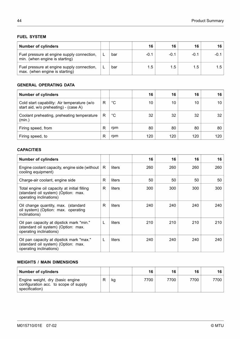
FUEL SYSTEM
Number of cylinders 16 16 16 16
Fuel pressure at engine supply connection,min. (when engine is starting)
L bar -0.1 -0.1 -0.1 -0.1
Fuel pressure at engine supply connection,max. (when engine is starting)
L bar 1.5 1.5 1.5 1.5
GENERAL OPERATING DATA
Number of cylinders 16 16 16 16
Cold start capability: Air temperature (w/ostart aid, w/o preheating) - (case A)
R °C 10 10 10 10
Coolant preheating, preheating temperature(min.)
R °C 32 32 32 32
Firing speed, from R rpm 80 80 80 80
Firing speed, to R rpm 120 120 120 120
CAPACITIES
Number of cylinders 16 16 16 16
Engine coolant capacity, engine side (withoutcooling equipment)
R liters 260 260 260 260
Charge-air coolant, engine side R liters 50 50 50 50
Total engine oil capacity at initial filling(standard oil system) (Option: max.operating inclinations)
R liters 300 300 300 300
Oil change quantity, max. (standardoil system) (Option: max. operatinginclinations)
R liters 240 240 240 240
Oil pan capacity at dipstick mark "min."(standard oil system) (Option: max.operating inclinations)
L liters 210 210 210 210
Oil pan capacity at dipstick mark "max."(standard oil system) (Option: max.operating inclinations)
L liters 240 240 240 240
WEIGHTS / MAIN DIMENSIONS
Number of cylinders 16 16 16 16
Engine weight, dry (basic engineconfiguration acc. to scope of supplyspecification)
R kg 7700 7700 7700 7700
M015710/01E 07-02 © MTU

Product Summary 45
ACOUSTICS
Number of cylinders 16 16 16 16
Exhaust noise, unsilenced - DL (soundpower level LW, ISO 6798)
R dB(A) 125 127 126 129
Engine surface noise with attenuated intakenoise (filter), DL (sound power level LW, ISO6798)
R dB(A) 126 125 128 125
M015710/01E 07-02 © MTU
46 Product Summary
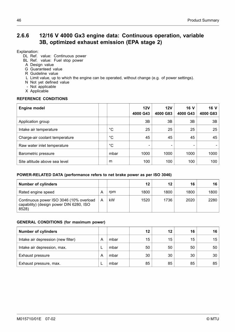
2.6.6 12/16 V 4000 Gx3 engine data: Continuous operation, variable3B, optimized exhaust emission (EPA stage 2)
Explanation:DL Ref. value: Continuous powerBL Ref. value: Fuel stop power
A Design valueG Guaranteed valueR Guideline valueL Limit value, up to which the engine can be operated, without change (e.g. of power settings).N Not yet defined value- Not applicable
X Applicable
REFERENCE CONDITIONS
Engine model 12V4000 G43
12V4000 G83
16 V4000 G43
16 V4000 G83
Application group 3B 3B 3B 3B
Intake air temperature °C 25 25 25 25
Charge-air coolant temperature °C 45 45 45 45
Raw water inlet temperature °C - - - -
Barometric pressure mbar 1000 1000 1000 1000
Site altitude above sea level m 100 100 100 100
POWER-RELATED DATA (performance refers to net brake power as per ISO 3046)
Number of cylinders 12 12 16 16
Rated engine speed A rpm 1800 1800 1800 1800
Continuous power ISO 3046 (10% overloadcapability) (design power DIN 6280, ISO8528)
A kW 1520 1736 2020 2280
GENERAL CONDITIONS (for maximum power)
Number of cylinders 12 12 16 16
Intake air depression (new filter) A mbar 15 15 15 15
Intake air depression, max. L mbar 50 50 50 50
Exhaust pressure A mbar 30 30 30 30
Exhaust pressure, max. L mbar 85 85 85 85
M015710/01E 07-02 © MTU

Product Summary 47
MODEL RELATED DATA (basic design)
Number of cylinders 12 12 16 16
Engine with exhaust turbocharging (ETC)and charge air cooling (CAC)
X X X X
Exhaust piping, non-cooled X X X X
Working method: four-cycle, diesel,single-acting
X X X X
Combustion method: Direct fuel injection X X X X
Cooling system: conditioned water X X X X
Direction of rotation: c.c.w. (facing drivingend)
X X X X
Number of cylinders 12 12 16 16
Cylinder arrangement: V angle Degrees 90 90 90 90
Bore mm 170 170 170 170
Stroke mm 210 210 210 210
Displacement per cylinder liters 4.77 4.77 4.77 4.77
Total displacement liters 57.2 57.2 76.3 76.3
Compression ratio 16.5 16.5 16.5 16.5
Cylinder heads: single-cylinder X X X X
Cylinder liners: Wet, replaceable X X X X
Inlet valves per cylinder 2 2 2 2
Exhaust valves per cylinder 2 2 2 2
Standard flywheel housing flange (enginemain PTO)
SAE 00 00 00 00
Flywheel interface DISC 21 21 21 21
COMBUSTION AIR / EXHAUST GAS
Number of cylinders 12 12 16 16
Charge air pressure before cylinder - DL R bar abs 3.0 3.1 3.0 3.2
M015710/01E 07-02 © MTU

48 Product Summary
COOLANT SYSTEM (HT circuit)
Number of cylinders 12 12 16 16
Coolant temperature (at engine connection:outlet to cooling equipment)
A °C 100 100 100 100
Coolant temperature after engine, alarm R °C 102 102 102 102
Coolant temperature after engine, shutdown L °C 104 104 104 104
Coolant antifreeze content, max. L % 50 50 50 50
Pressure loss in off-engine cooling system,max.
L bar 0.7 0.7 0.7 0.7
COOLING SYSTEM (LT circuit)
Number of cylinders 12 12 16 16
Coolant temperature before intercooler (atengine inlet from cooling equipment)
A °C 45 45 45 45
Coolant antifreeze content, max. L % 50 50 50 50
Pressure loss in off-engine cooling system,max.
L bar 0.7 0.7 0.7 0.7
LUBE-OIL SYSTEM
Number of cylinders 12 12 16 16
Lube oil operating temperature beforeengine, from
R °C 88 88 90 88
Lube-oil operating temperature beforeengine, to
R °C 98 98 96 94
Lube oil temperature before engine, alarm R °C 99 99 97 97
Lube oil temperature before engine,shutdown
L °C 101 101 99 99
Lube oil operating pressure before engine,from
R bar 5.0 5.0 4.7 4.7
Lube oil operating pressure before engine, to R bar 7.0 7.0 6.5 6.5
Lube oil pressure before engine, alarm R bar -- -- -- --
Lube oil pressure before engine, shutdown L bar -- -- -- --
M015710/01E 07-02 © MTU
Product Summary 49
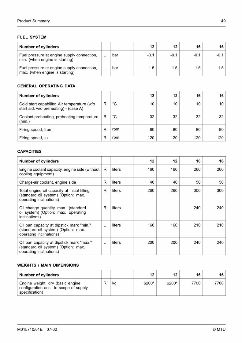
FUEL SYSTEM
Number of cylinders 12 12 16 16
Fuel pressure at engine supply connection,min. (when engine is starting)
L bar -0.1 -0.1 -0.1 -0.1
Fuel pressure at engine supply connection,max. (when engine is starting)
L bar 1.5 1.5 1.5 1.5
GENERAL OPERATING DATA
Number of cylinders 12 12 16 16
Cold start capability: Air temperature (w/ostart aid, w/o preheating) - (case A)
R °C 10 10 10 10
Coolant preheating, preheating temperature(min.)
R °C 32 32 32 32
Firing speed, from R rpm 80 80 80 80
Firing speed, to R rpm 120 120 120 120
CAPACITIES
Number of cylinders 12 12 16 16
Engine coolant capacity, engine side (withoutcooling equipment)
R liters 160 160 260 260
Charge-air coolant, engine side R liters 40 40 50 50
Total engine oil capacity at initial filling(standard oil system) (Option: max.operating inclinations)
R liters 260 260 300 300
Oil change quantity, max. (standardoil system) (Option: max. operatinginclinations)
R liters 240 240
Oil pan capacity at dipstick mark "min."(standard oil system) (Option: max.operating inclinations)
L liters 160 160 210 210
Oil pan capacity at dipstick mark "max."(standard oil system) (Option: max.operating inclinations)
L liters 200 200 240 240
WEIGHTS / MAIN DIMENSIONS
Number of cylinders 12 12 16 16
Engine weight, dry (basic engineconfiguration acc. to scope of supplyspecification)
R kg 6200* 6200* 7700 7700
M015710/01E 07-02 © MTU
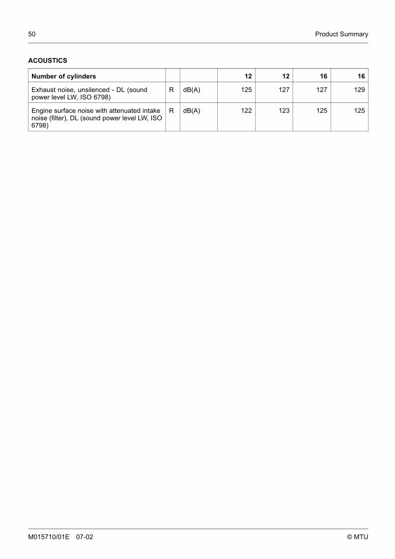
50 Product Summary
ACOUSTICS
Number of cylinders 12 12 16 16
Exhaust noise, unsilenced - DL (soundpower level LW, ISO 6798)
R dB(A) 125 127 127 129
Engine surface noise with attenuated intakenoise (filter), DL (sound power level LW, ISO6798)
R dB(A) 122 123 125 125
M015710/01E 07-02 © MTU

Product Summary 51
2.6.7 12V 4000 Gx3 engine data: Continuous operation, variable3B, optimized exhaust emissions (TA-Luft)
Explanation:DL Ref. value: Continuous powerBL Ref. value: Fuel stop power
A Design valueG Guaranteed valueR Guideline valueL Limit value, up to which the engine can be operated, without change (e.g. of power settings).N Not yet defined value- Not applicable
X Applicable
REFERENCE CONDITIONS
Engine model 12V4000 G23
12V4000 G63
Application group 3B 3B
Intake air temperature °C 25 25
Charge-air coolant temperature °C 55 55
Raw water inlet temperature °C - -
Barometric pressure mbar 1000 1000
Site altitude above sea level m 100 100
POWER-RELATED DATA (performance refers to net brake power as per ISO 3046)
Number of cylinders 12 12
Rated engine speed A rpm 1500 1500
Continuous power ISO 3046 (10% overload capability) (design powerDIN 6280, ISO 8528)
A kW 1420 1575
GENERAL CONDITIONS (for maximum power)
Number of cylinders 12 12
Intake air depression (new filter) A mbar 15 15
Intake air depression, max. L mbar 50 50
Exhaust pressure A mbar 30 30
Exhaust pressure, max. L mbar 85 85
M015710/01E 07-02 © MTU
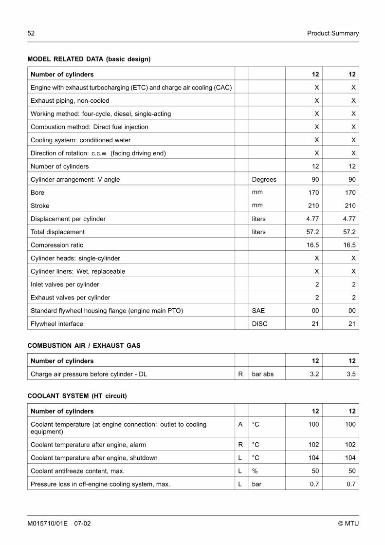
52 Product Summary
MODEL RELATED DATA (basic design)
Number of cylinders 12 12
Engine with exhaust turbocharging (ETC) and charge air cooling (CAC) X X
Exhaust piping, non-cooled X X
Working method: four-cycle, diesel, single-acting X X
Combustion method: Direct fuel injection X X
Cooling system: conditioned water X X
Direction of rotation: c.c.w. (facing driving end) X X
Number of cylinders 12 12
Cylinder arrangement: V angle Degrees 90 90
Bore mm 170 170
Stroke mm 210 210
Displacement per cylinder liters 4.77 4.77
Total displacement liters 57.2 57.2
Compression ratio 16.5 16.5
Cylinder heads: single-cylinder X X
Cylinder liners: Wet, replaceable X X
Inlet valves per cylinder 2 2
Exhaust valves per cylinder 2 2
Standard flywheel housing flange (engine main PTO) SAE 00 00
Flywheel interface DISC 21 21
COMBUSTION AIR / EXHAUST GAS
Number of cylinders 12 12
Charge air pressure before cylinder - DL R bar abs 3.2 3.5
COOLANT SYSTEM (HT circuit)
Number of cylinders 12 12
Coolant temperature (at engine connection: outlet to coolingequipment)
A °C 100 100
Coolant temperature after engine, alarm R °C 102 102
Coolant temperature after engine, shutdown L °C 104 104
Coolant antifreeze content, max. L % 50 50
Pressure loss in off-engine cooling system, max. L bar 0.7 0.7
M015710/01E 07-02 © MTU
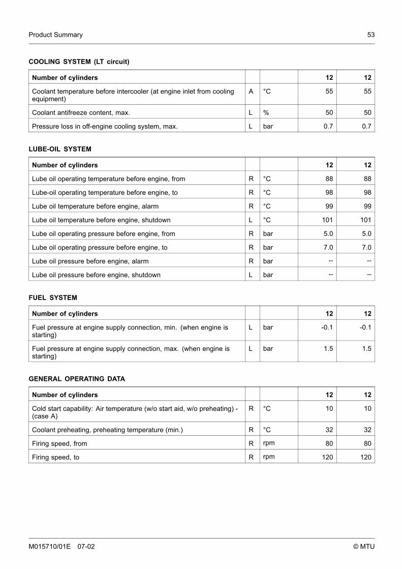
Product Summary 53
COOLING SYSTEM (LT circuit)
Number of cylinders 12 12
Coolant temperature before intercooler (at engine inlet from coolingequipment)
A °C 55 55
Coolant antifreeze content, max. L % 50 50
Pressure loss in off-engine cooling system, max. L bar 0.7 0.7
LUBE-OIL SYSTEM
Number of cylinders 12 12
Lube oil operating temperature before engine, from R °C 88 88
Lube-oil operating temperature before engine, to R °C 98 98
Lube oil temperature before engine, alarm R °C 99 99
Lube oil temperature before engine, shutdown L °C 101 101
Lube oil operating pressure before engine, from R bar 5.0 5.0
Lube oil operating pressure before engine, to R bar 7.0 7.0
Lube oil pressure before engine, alarm R bar -- --
Lube oil pressure before engine, shutdown L bar -- --
FUEL SYSTEM
Number of cylinders 12 12
Fuel pressure at engine supply connection, min. (when engine isstarting)
L bar -0.1 -0.1
Fuel pressure at engine supply connection, max. (when engine isstarting)
L bar 1.5 1.5
GENERAL OPERATING DATA
Number of cylinders 12 12
Cold start capability: Air temperature (w/o start aid, w/o preheating) -(case A)
R °C 10 10
Coolant preheating, preheating temperature (min.) R °C 32 32
Firing speed, from R rpm 80 80
Firing speed, to R rpm 120 120
M015710/01E 07-02 © MTU
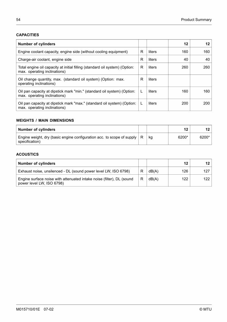
54 Product Summary
CAPACITIES
Number of cylinders 12 12
Engine coolant capacity, engine side (without cooling equipment) R liters 160 160
Charge-air coolant, engine side R liters 40 40
Total engine oil capacity at initial filling (standard oil system) (Option:max. operating inclinations)
R liters 260 260
Oil change quantity, max. (standard oil system) (Option: max.operating inclinations)
R liters
Oil pan capacity at dipstick mark "min." (standard oil system) (Option:max. operating inclinations)
L liters 160 160
Oil pan capacity at dipstick mark "max." (standard oil system) (Option:max. operating inclinations)
L liters 200 200
WEIGHTS / MAIN DIMENSIONS
Number of cylinders 12 12
Engine weight, dry (basic engine configuration acc. to scope of supplyspecification)
R kg 6200* 6200*
ACOUSTICS
Number of cylinders 12 12
Exhaust noise, unsilenced - DL (sound power level LW, ISO 6798) R dB(A) 126 127
Engine surface noise with attenuated intake noise (filter), DL (soundpower level LW, ISO 6798)
R dB(A) 122 122
M015710/01E 07-02 © MTU

Operation 55
3 Operation
3.1 Putting the engine into operation after extendedout-of-service-periods (>3 months)
Preconditions• Engine is stopped and starting disabled.• MTU Fluids and Lubricants Specifications (A001061/..) are available.
Putting the engine into operation after extended out-of-service-periods (>3 months)
Item Task
Engine Depreserve (→MTU Fluids and Lubricants Specifications A001061/..).
Valve gear Lubricate valve gear every ≥ 6 months (→ Page 104).
Lube oil system Check engine oil level (→ Page 134).
Fuel prefilter Prime (→ Page 122).
Fuel prefilter, pressure gauge Align adjustable pointer with position of pressure indicator (→ Page 117).
Coolant circuit If engine is out of service for more than one year, change engine coolant(→ Page 139);Change charge-air coolant (→ Page 146).
Coolant circuit Check engine coolant level (→ Page 143);Check charge-air coolant level (→ Page 150).
Coolant circuit Preheat coolant with preheating unit.
ECU Check plug-in connections (→ Page 157).
Monitoring equipment Carry out lamp test (see manufacturer’s documentation).
Engine/generator controlsystem
Switch ON;Select operating mode, e.g. MANUAL OPERATION, AUTOMATIC OPERATION.
M015710/01E 07-02 © MTU
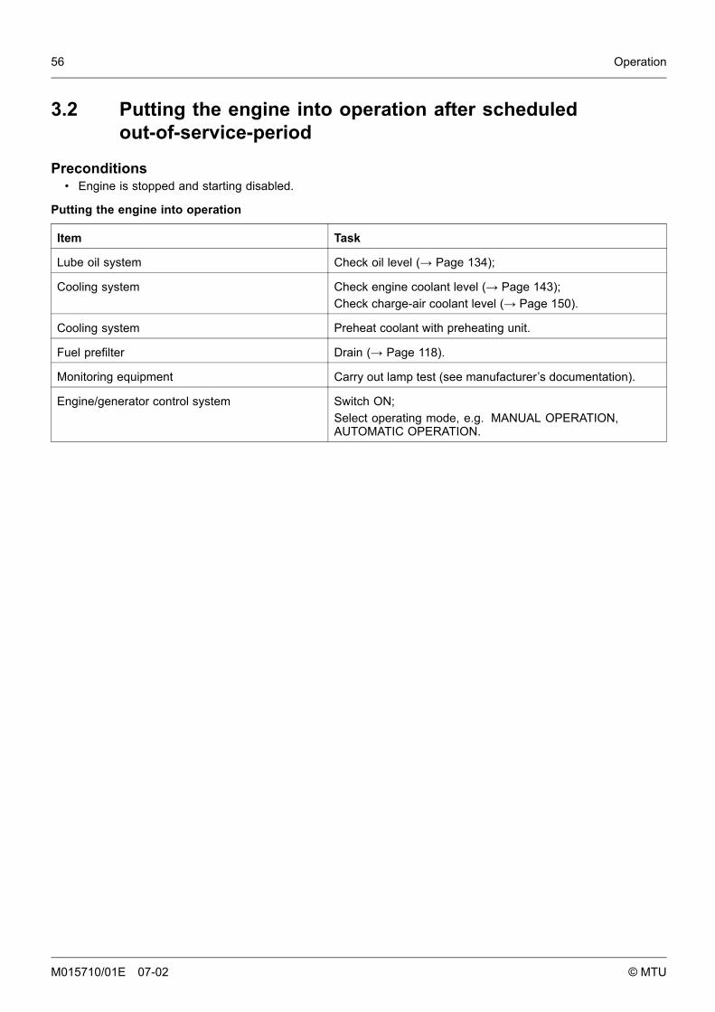
56 Operation
3.2 Putting the engine into operation after scheduledout-of-service-period
Preconditions• Engine is stopped and starting disabled.
Putting the engine into operation
Item Task
Lube oil system Check oil level (→ Page 134);
Cooling system Check engine coolant level (→ Page 143);Check charge-air coolant level (→ Page 150).
Cooling system Preheat coolant with preheating unit.
Fuel prefilter Drain (→ Page 118).
Monitoring equipment Carry out lamp test (see manufacturer’s documentation).
Engine/generator control system Switch ON;Select operating mode, e.g. MANUAL OPERATION,AUTOMATIC OPERATION.
M015710/01E 07-02 © MTU
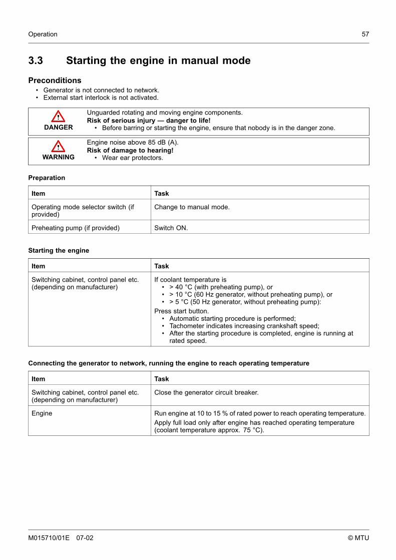
Operation 57
3.3 Starting the engine in manual mode
Preconditions• Generator is not connected to network.• External start interlock is not activated.
DANGER
Unguarded rotating and moving engine components.Risk of serious injury — danger to life!
• Before barring or starting the engine, ensure that nobody is in the danger zone.
WARNING
Engine noise above 85 dB (A).Risk of damage to hearing!
• Wear ear protectors.
Preparation
Item Task
Operating mode selector switch (ifprovided)
Change to manual mode.
Preheating pump (if provided) Switch ON.
Starting the engine
Item Task
Switching cabinet, control panel etc.(depending on manufacturer)
If coolant temperature is• > 40 °C (with preheating pump), or• > 10 °C (60 Hz generator, without preheating pump), or• > 5 °C (50 Hz generator, without preheating pump):
Press start button.• Automatic starting procedure is performed;• Tachometer indicates increasing crankshaft speed;• After the starting procedure is completed, engine is running at
rated speed.
Connecting the generator to network, running the engine to reach operating temperature
Item Task
Switching cabinet, control panel etc.(depending on manufacturer)
Close the generator circuit breaker.
Engine Run engine at 10 to 15 % of rated power to reach operating temperature.Apply full load only after engine has reached operating temperature(coolant temperature approx. 75 °C).
M015710/01E 07-02 © MTU
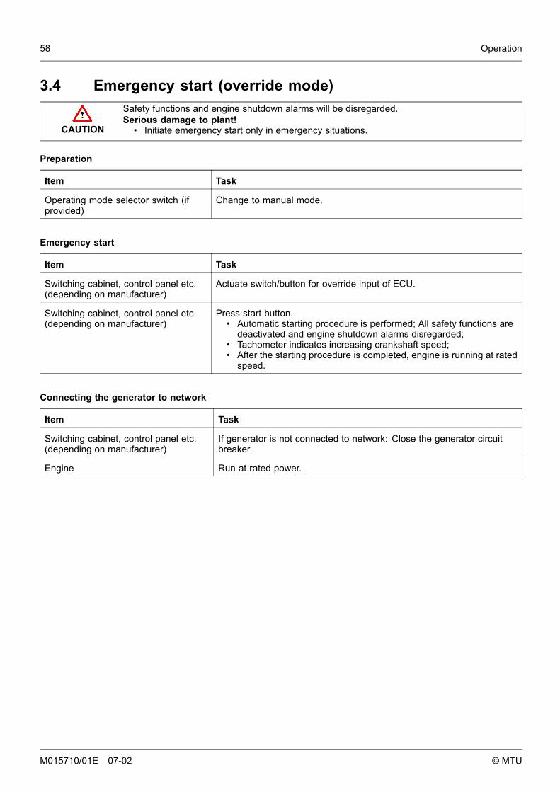
58 Operation
3.4 Emergency start (override mode)
CAUTION
Safety functions and engine shutdown alarms will be disregarded.Serious damage to plant!
• Initiate emergency start only in emergency situations.
Preparation
Item Task
Operating mode selector switch (ifprovided)
Change to manual mode.
Emergency start
Item Task
Switching cabinet, control panel etc.(depending on manufacturer)
Actuate switch/button for override input of ECU.
Switching cabinet, control panel etc.(depending on manufacturer)
Press start button.• Automatic starting procedure is performed; All safety functions are
deactivated and engine shutdown alarms disregarded;• Tachometer indicates increasing crankshaft speed;• After the starting procedure is completed, engine is running at rated
speed.
Connecting the generator to network
Item Task
Switching cabinet, control panel etc.(depending on manufacturer)
If generator is not connected to network: Close the generator circuitbreaker.
Engine Run at rated power.
M015710/01E 07-02 © MTU
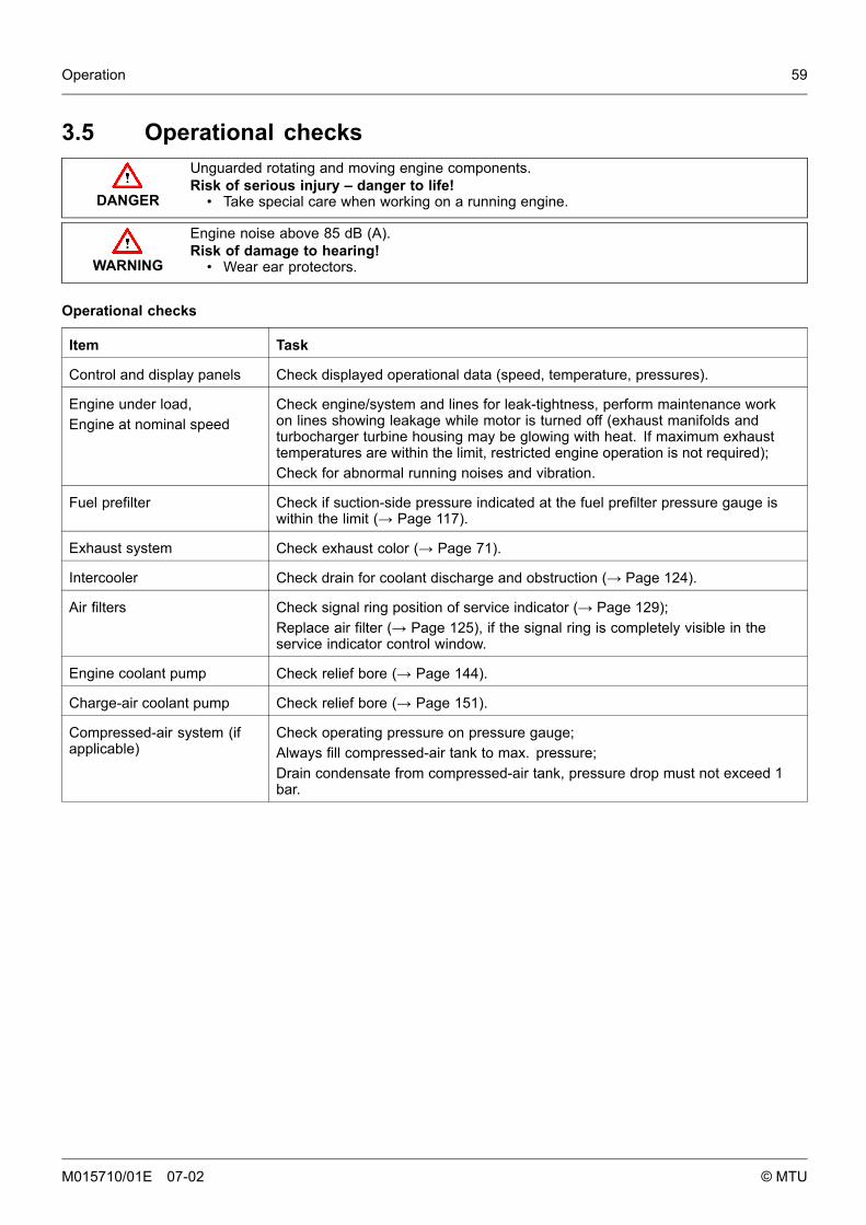
Operation 59
3.5 Operational checks
DANGER
Unguarded rotating and moving engine components.Risk of serious injury – danger to life!
• Take special care when working on a running engine.
WARNING
Engine noise above 85 dB (A).Risk of damage to hearing!
• Wear ear protectors.
Operational checks
Item Task
Control and display panels Check displayed operational data (speed, temperature, pressures).
Engine under load,Engine at nominal speed
Check engine/system and lines for leak-tightness, perform maintenance workon lines showing leakage while motor is turned off (exhaust manifolds andturbocharger turbine housing may be glowing with heat. If maximum exhausttemperatures are within the limit, restricted engine operation is not required);Check for abnormal running noises and vibration.
Fuel prefilter Check if suction-side pressure indicated at the fuel prefilter pressure gauge iswithin the limit (→ Page 117).
Exhaust system Check exhaust color (→ Page 71).
Intercooler Check drain for coolant discharge and obstruction (→ Page 124).
Air filters Check signal ring position of service indicator (→ Page 129);Replace air filter (→ Page 125), if the signal ring is completely visible in theservice indicator control window.
Engine coolant pump Check relief bore (→ Page 144).
Charge-air coolant pump Check relief bore (→ Page 151).
Compressed-air system (ifapplicable)
Check operating pressure on pressure gauge;Always fill compressed-air tank to max. pressure;Drain condensate from compressed-air tank, pressure drop must not exceed 1bar.
M015710/01E 07-02 © MTU
60 Operation
3.6 Stopping the engine in manual mode
Preconditions• Generator is not connected to network.• Engine is running in manual mode.
CAUTION
Stopping the engine when it is running at full load causes extreme stress to the engine.Risk of overheating, damage to components!
• Before stopping the engine, operate it at idle speed until operating temperatures decreaseand stable values are indicated.
Preparation
Item Task
Engine After the generator circuit breaker has been opened, allow the engine tocool down by running it idle for approx. 5 minutes.
Stopping the engine
Item Task
Switching cabinet, control panel etc.(depending on manufacturer)
Press stop button.• Automatic stopping procedure is performed;• Engine is stopped.
After stopping the engine
Item Task
Cooling pump Operate for approx. 5 minutes after engine stop.
M015710/01E 07-02 © MTU
Operation 61
3.7 Emergency stop
CAUTION
An emergency stop causes extreme stress to the engine.Risk of overheating, damage to components!
• Initiate emergency stop only in emergency situations.
Emergency stop from LOP
Item Task
EMERGENCY STOP button Press.• Engine is stopped by switching off power supply to ECU;• Signalization (e.g. by horn, flashing lamp) is released.
After emergency stop from LOP
Item Task
Switching cabinet, control panel etc.(depending on manufacturer)
Press button for alarm acknowledgement.• Audible and visual signalization stops.
M015710/01E 07-02 © MTU
62 Operation
3.8 After stopping the engine – engine remainsready for operation
After stopping the engine
Item Task
Engine/generator control system Select operating mode, e.g. MANUAL OPERATION, AUTOMATICOPERATION.
M015710/01E 07-02 © MTU
Operation 63
3.9 After stopping the engine – putting the engine out of service
Preconditions• MTU Fluids and Lubricants Specification (A001061/..) is available.
After stopping the engine
Item Task
Cooling system Drain engine coolant (→ Page 142);Drain charge-air coolant (→ Page 149) if:
• freezing temperatures are expected and the engine is toremain out of service for an extended period and coolanthas no antifreeze additive;
• the engine room is not heated;• the coolant is not maintained at a suitable temperature;• the antifreeze concentration is insufficient for the engine-room
temperature;• antifreeze concentration is 50% and engine-room
temperature is below -40°C.
Engine/generator control system Switch OFF.
Air intake and exhaust system If the engine is to remain out of service for more than 1 week, sealthe engine’s air and exhaust sides. If the engine is to remain outof service for more than 1 month, carry out preservation (→MTUFluids and Lubricants Specification A001061/..).
M015710/01E 07-02 © MTU
64 Operation
M015710/01E 07-02 © MTU
Maintenance 65
4 Maintenance
4.1 Preface
MTU maintenance conceptThe maintenance system for MTU products is based on a preventive maintenance concept. Preventivemaintenance facilitates advance planning and ensures a high level of equipment availability.The maintenance schedule is based on the load profile / load factor specified below. The time intervals at whichthe maintenance work is to be carried out and the relevant checks and tasks involved are average values basedon operational experience and are therefore to be regarded as guidelines only. Special operating conditionsand technical requirements may require additional maintenance work and/or modifications of the maintenanceintervals. Maintenance personnel charged with carrying out maintenance work must be appropriately qualifieddepending on the complexity of the task concerned. The various Qualification Levels QL1 to QL4 reflectthe levels of training offered in MTU courses and the contents of the tool kits required:
QL1: Operational monitoring and maintenance which can be carried out during a breakin operation without disassembling the engine.
QL2: Exchange of components (corrective only).QL3: Maintenance work which requires partial disassembly of the engine.QL4: Maintenance work which requires complete disassembly of the engine.
The maintenance schedule matrix normally finishes with extended component maintenance. Followingthis, maintenance work is to be continued at the intervals indicated.The "Task" numbers stated in the list of jobs to be done/action to be taken indicate the relevant maintenance item. Theyserve as a reference for the scope of parts needed and also appear on the labels of the corresponding spare parts.
Preventive maintenance instructionsSpecifications for fluids and lubricants, guideline values for their maintenance and change intervals and lists ofrecommended fluids and lubricants are contained in the MTU Fluids and Lubricants Specifications A001061 and inthe fluids and lubricants specifications produced by the component manufacturers. They are therefore not listed inthe maintenance schedule (exception: deviations from the Fluids and Lubricants Specifications). Only use fluidsand lubricants which meet MTU specifications or are approved by the component manufacturer concerned.Amongst other items, the operator/customer must perform the following additional maintenance work:
• Protect components made of rubber or synthetic material from oil. Never treat themwith organic detergents. Wipe with a dry cloth only.
• Fuel prefilter:The maintenance interval depends on how dirty the fuel is. The paper inserts in fuel prefiltersmust be replaced every 2 years at the latest (Task 9998).
• Battery:Battery maintenance depends on use and ambient conditions. The batterymanufacturer’s instructions must be obeyed.
The relevant manufacturer’s instructions apply with respect to the maintenance of any componentswhich do not appear in this maintenance schedule.Items that are listed in this maintenance schedule but that do not refer to the respective engine model, can be ignored.
Out-of-service periodsIf the engine is to remain out of service for more than 1 month, carry out engine preservation procedures inaccordance with the MTU Fluids and Lubricants Specifications, Publication No. A001061/.
Application group
3B Continuous operation, variable
3D Standby operation
M015710/01E 07-02 © MTU
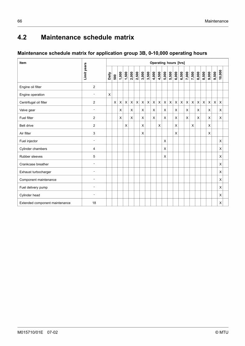
66 Maintenance
4.2 Maintenance schedule matrix
Maintenance schedule matrix for application group 3B, 0-10,000 operating hours
Operating hours [hrs]Item
Lim
itye
ars
Dai
ly50
01,
000
1,50
02,
000
2,50
03,
000
3,50
04,
000
4,50
05,
000
5,50
06,
000
6,50
07,
000
7,50
08,
000
8,50
09,
000
9,50
010
,000
Engine oil filter 2
Engine operation - X
Centrifugal oil filter 2 X X X X X X X X X X X X X X X X X X X X
Valve gear - X X X X X X X X X X
Fuel filter 2 X X X X X X X X X X
Belt drive 2 X X X X X X
Air filter 3 X X X
Fuel injector - X X
Cylinder chambers 4 X X
Rubber sleeves 5 X X
Crankcase breather - X
Exhaust turbocharger - X
Component maintenance - X
Fuel delivery pump - X
Cylinder head - X
Extended component maintenance 18 X
M015710/01E 07-02 © MTU
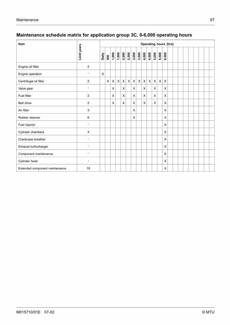
Maintenance 67
Maintenance schedule matrix for application group 3C, 0-6,000 operating hours
Operating hours [hrs]Item
Lim
itye
ars
Dai
ly50
01,
000
1,50
02,
000
2,50
03,
000
3,50
04,
000
4,50
05,
000
5,50
06,
000
Engine oil filter 2
Engine operation - X
Centrifugal oil filter 2 X X X X X X X X X X X X
Valve gear - X X X X X X
Fuel filter 2 X X X X X X
Belt drive 2 X X X X X X
Air filter 3 X X
Rubber sleeves 6 X X
Fuel injector - X
Cylinder chambers 4 X
Crankcase breather - X
Exhaust turbocharger - X
Component maintenance - X
Cylinder head - X
Extended component maintenance 18 X
M015710/01E 07-02 © MTU
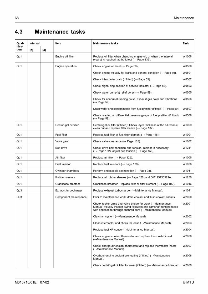
68 Maintenance
4.3 Maintenance tasks
IntervalQual-ifica-tion [h] [a]
Item Maintenance tasks Task
QL1 Engine oil filter Replace oil filter when changing engine oil, or when the interval(years) is reached, at the latest (→ Page 136).
W1008
QL1 Engine operation Check engine oil level (→ Page 59). W0500
Check engine visually for leaks and general condition (→ Page 59). W0501
Check intercooler drain (if fitted) (→ Page 59). W0502
Check signal ring position of service indicator (→ Page 59). W0503
Check water pump(s) relief bores (→ Page 59). W0505
Check for abnormal running noise, exhaust gas color and vibrations(→ Page 59).
W0506
Drain water and contaminants from fuel prefilter (if fitted) (→ Page 59). W0507
Check reading on differential pressure gauge of fuel prefilter (if fitted)(→ Page 59).
W0508
QL1 Centrifugal oil filter Centrifugal oil filter (if fitted): Check layer thickness of the oil residue,clean out and replace filter sleeve (→ Page 137).
W1009
QL1 Fuel filter Replace fuel filter or fuel filter element (→ Page 115). W1001
QL1 Valve gear Check valve clearance (→ Page 105). W1002
QL1 Belt drive Check drive belt condition and tension, replace if necessary(→ Page 152); adjust belt tension (→ Page 153).
W1241
QL1 Air filter Replace air filter (→ Page 125). W1005
QL1 Fuel injector Replace fuel injectors (→ Page 109). W1006
QL1 Cylinder chambers Perform endoscopic examination (→ Page 98). W1011
QL1 Rubber sleeves Replace all rubber sleeves (→ Page 128) and DM125150921A. W1250
QL1 Crankcase breather Crankcase breather: Replace filter or filter element (→ Page 102). W1046
QL3 Exhaust turbocharger Replace exhaust turbocharger (→Maintenance Manual). W1041
QL3 Component maintenance Prior to maintenance work, drain coolant and flush coolant circuits. W2000
Check rocker arms and valve bridge for wear (→MaintenanceManual) visually inspect swing followers and camshaft running faceswith endoscope through pushrod bore (→Maintenance Manual).
W2001
Clean air system (→Maintenance Manual). W2002
Clean intercooler and check for leaks (→Maintenance Manual). W2003
Replace fuel HP sensor (→Maintenance Manual). W2004
Check engine coolant thermostat and replace thermostat insert(→Maintenance Manual).
W2006
Check charge-air coolant thermostat and replace thermostat insert(→Maintenance Manual).
W2007
Overhaul engine coolant preheating (if fitted) (→MaintenanceManual).
W2008
Check centrifugal oil filter for wear (if fitted) (→ Maintenance Manual). W2009
M015710/01E 07-02 © MTU
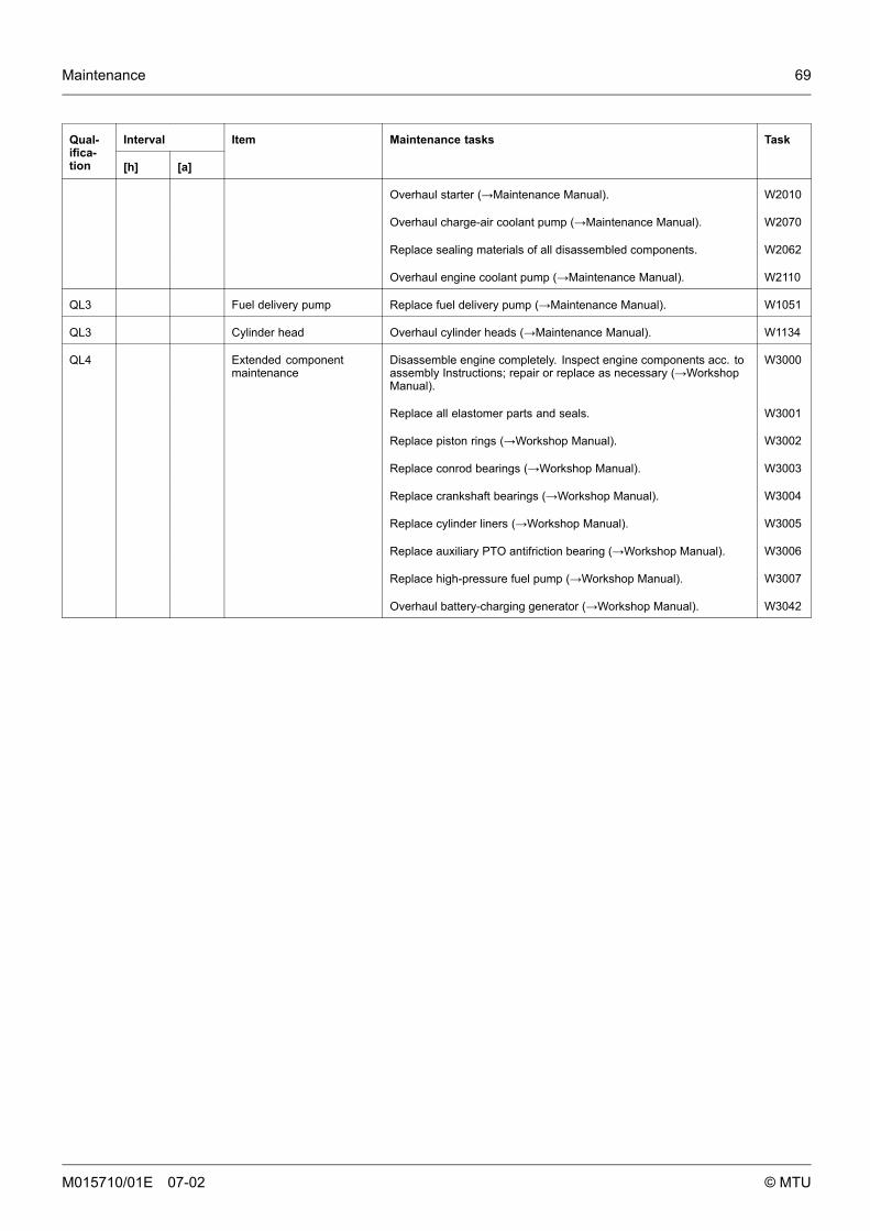
Maintenance 69
IntervalQual-ifica-tion [h] [a]
Item Maintenance tasks Task
Overhaul starter (→Maintenance Manual). W2010
Overhaul charge-air coolant pump (→Maintenance Manual). W2070
Replace sealing materials of all disassembled components. W2062
Overhaul engine coolant pump (→Maintenance Manual). W2110
QL3 Fuel delivery pump Replace fuel delivery pump (→Maintenance Manual). W1051
QL3 Cylinder head Overhaul cylinder heads (→Maintenance Manual). W1134
QL4 Extended componentmaintenance
Disassemble engine completely. Inspect engine components acc. toassembly Instructions; repair or replace as necessary (→WorkshopManual).
W3000
Replace all elastomer parts and seals. W3001
Replace piston rings (→Workshop Manual). W3002
Replace conrod bearings (→Workshop Manual). W3003
Replace crankshaft bearings (→Workshop Manual). W3004
Replace cylinder liners (→Workshop Manual). W3005
Replace auxiliary PTO antifriction bearing (→Workshop Manual). W3006
Replace high-pressure fuel pump (→Workshop Manual). W3007
Overhaul battery-charging generator (→Workshop Manual). W3042
M015710/01E 07-02 © MTU
70 Maintenance
M015710/01E 07-02 © MTU
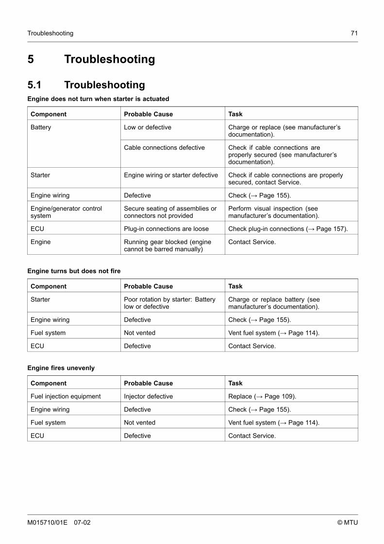
Troubleshooting 71
5 Troubleshooting
5.1 TroubleshootingEngine does not turn when starter is actuated
Component Probable Cause Task
Low or defective Charge or replace (see manufacturer’sdocumentation).
Battery
Cable connections defective Check if cable connections areproperly secured (see manufacturer’sdocumentation).
Starter Engine wiring or starter defective Check if cable connections are properlysecured, contact Service.
Engine wiring Defective Check (→ Page 155).
Engine/generator controlsystem
Secure seating of assemblies orconnectors not provided
Perform visual inspection (seemanufacturer’s documentation).
ECU Plug-in connections are loose Check plug-in connections (→ Page 157).
Engine Running gear blocked (enginecannot be barred manually)
Contact Service.
Engine turns but does not fire
Component Probable Cause Task
Starter Poor rotation by starter: Batterylow or defective
Charge or replace battery (seemanufacturer’s documentation).
Engine wiring Defective Check (→ Page 155).
Fuel system Not vented Vent fuel system (→ Page 114).
ECU Defective Contact Service.
Engine fires unevenly
Component Probable Cause Task
Fuel injection equipment Injector defective Replace (→ Page 109).
Engine wiring Defective Check (→ Page 155).
Fuel system Not vented Vent fuel system (→ Page 114).
ECU Defective Contact Service.
M015710/01E 07-02 © MTU
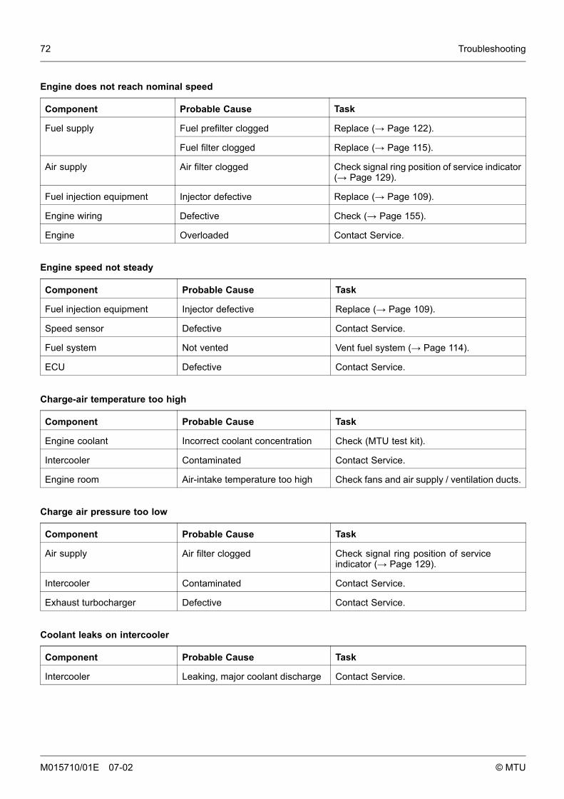
72 Troubleshooting
Engine does not reach nominal speed
Component Probable Cause Task
Fuel prefilter clogged Replace (→ Page 122).Fuel supply
Fuel filter clogged Replace (→ Page 115).
Air supply Air filter clogged Check signal ring position of service indicator(→ Page 129).
Fuel injection equipment Injector defective Replace (→ Page 109).
Engine wiring Defective Check (→ Page 155).
Engine Overloaded Contact Service.
Engine speed not steady
Component Probable Cause Task
Fuel injection equipment Injector defective Replace (→ Page 109).
Speed sensor Defective Contact Service.
Fuel system Not vented Vent fuel system (→ Page 114).
ECU Defective Contact Service.
Charge-air temperature too high
Component Probable Cause Task
Engine coolant Incorrect coolant concentration Check (MTU test kit).
Intercooler Contaminated Contact Service.
Engine room Air-intake temperature too high Check fans and air supply / ventilation ducts.
Charge air pressure too low
Component Probable Cause Task
Air supply Air filter clogged Check signal ring position of serviceindicator (→ Page 129).
Intercooler Contaminated Contact Service.
Exhaust turbocharger Defective Contact Service.
Coolant leaks on intercooler
Component Probable Cause Task
Intercooler Leaking, major coolant discharge Contact Service.
M015710/01E 07-02 © MTU
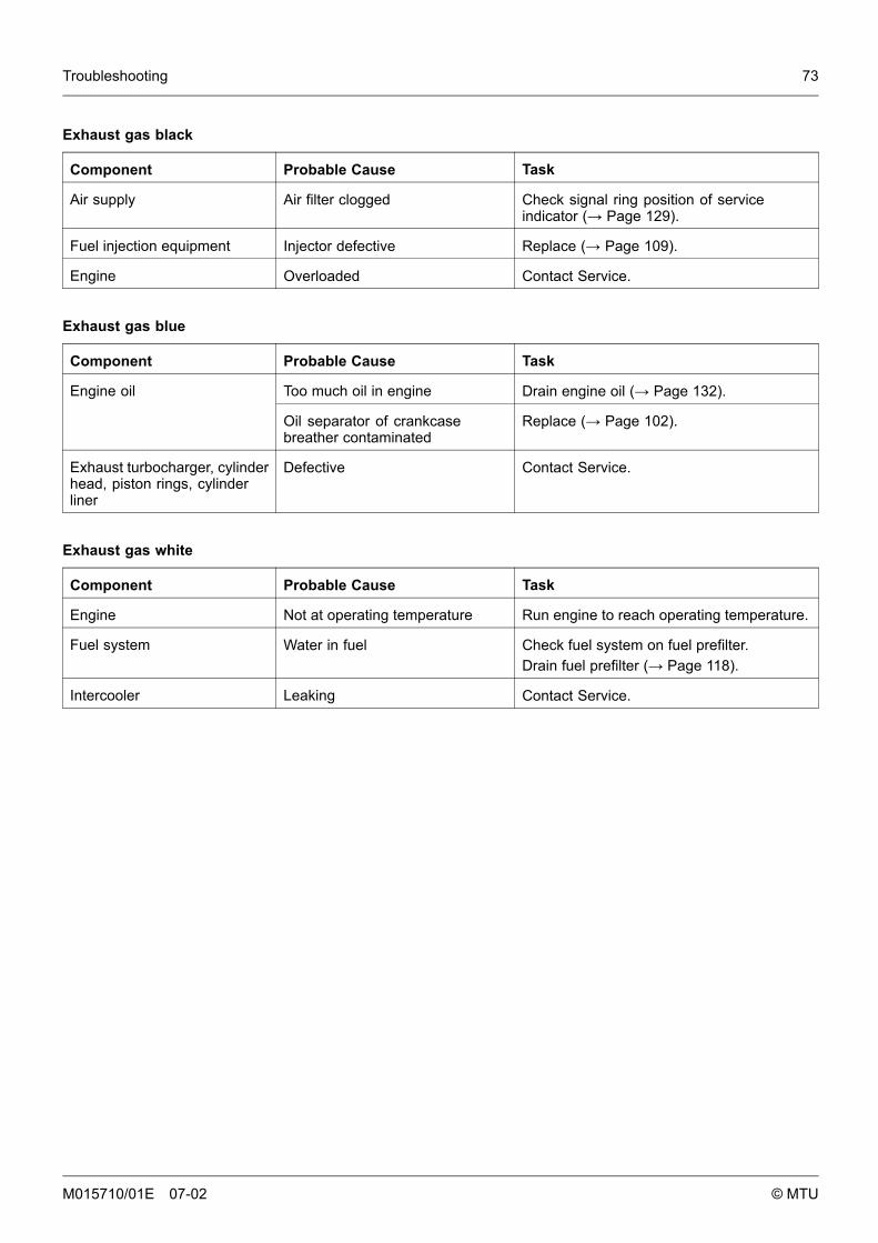
Troubleshooting 73
Exhaust gas black
Component Probable Cause Task
Air supply Air filter clogged Check signal ring position of serviceindicator (→ Page 129).
Fuel injection equipment Injector defective Replace (→ Page 109).
Engine Overloaded Contact Service.
Exhaust gas blue
Component Probable Cause Task
Too much oil in engine Drain engine oil (→ Page 132).Engine oil
Oil separator of crankcasebreather contaminated
Replace (→ Page 102).
Exhaust turbocharger, cylinderhead, piston rings, cylinderliner
Defective Contact Service.
Exhaust gas white
Component Probable Cause Task
Engine Not at operating temperature Run engine to reach operating temperature.
Fuel system Water in fuel Check fuel system on fuel prefilter.Drain fuel prefilter (→ Page 118).
Intercooler Leaking Contact Service.
M015710/01E 07-02 © MTU
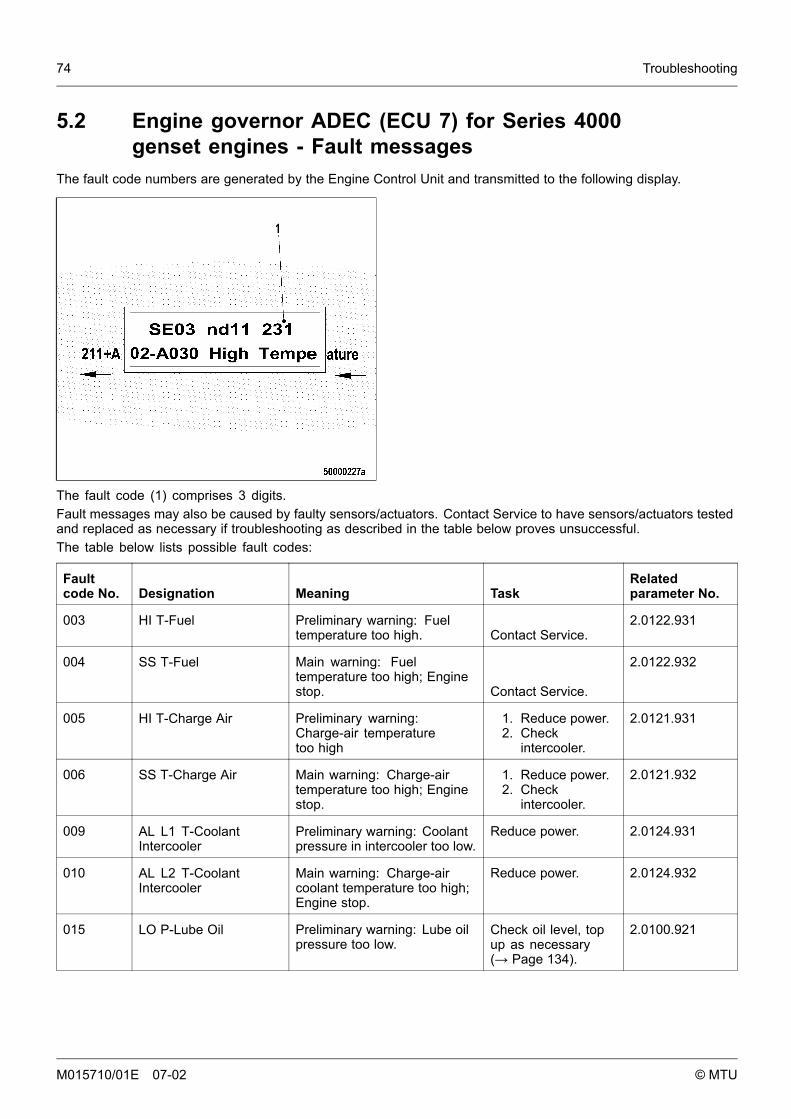
74 Troubleshooting
5.2 Engine governor ADEC (ECU 7) for Series 4000genset engines - Fault messages
The fault code numbers are generated by the Engine Control Unit and transmitted to the following display.
The fault code (1) comprises 3 digits.Fault messages may also be caused by faulty sensors/actuators. Contact Service to have sensors/actuators testedand replaced as necessary if troubleshooting as described in the table below proves unsuccessful.The table below lists possible fault codes:
Faultcode No. Designation Meaning Task
Relatedparameter No.
003 HI T-Fuel Preliminary warning: Fueltemperature too high. Contact Service.
2.0122.931
004 SS T-Fuel Main warning: Fueltemperature too high; Enginestop. Contact Service.
2.0122.932
005 HI T-Charge Air Preliminary warning:Charge-air temperaturetoo high
1. Reduce power.2. Check
intercooler.
2.0121.931
006 SS T-Charge Air Main warning: Charge-airtemperature too high; Enginestop.
1. Reduce power.2. Check
intercooler.
2.0121.932
009 AL L1 T-CoolantIntercooler
Preliminary warning: Coolantpressure in intercooler too low.
Reduce power. 2.0124.931
010 AL L2 T-CoolantIntercooler
Main warning: Charge-aircoolant temperature too high;Engine stop.
Reduce power. 2.0124.932
015 LO P-Lube Oil Preliminary warning: Lube oilpressure too low.
Check oil level, topup as necessary(→ Page 134).
2.0100.921
M015710/01E 07-02 © MTU

Troubleshooting 75
Faultcode No. Designation Meaning Task
Relatedparameter No.
016 SS P-Lube Oil Main warning: Lube oilpressure too low; Engine willbe shut down.
1. Check oillevel, top upas necessary(→ Page 134).
2. Attempt torestart engine(→ Page 57).
2.0100.922
019 HI T-Exhaust A Preliminary warning: Exhausttemperature (A-side) too high.
1. Check cabling(→ Page 155).
2. ContactService.
2.0126.931
020 SS T-Exhaust A Main warning: Exhausttemperature (A-side) too high.Engine stop.
1. Check cabling(→ Page 155).
2. ContactService.
2.0126.932
021 HI T-Exhaust B Preliminary warning: Exhausttemperature (B-side) too high.
1. Check cabling(→ Page 155).
2. ContactService.
2.0127.931
022 SS T-Exhaust B Main warning: Exhausttemperature (B-side) too high.Engine stop.
1. Check cabling(→ Page 155).
2. ContactService.
2.0127.932
023 LO Coolant Level Alarm configuration limit value1; Coolant level too low.
Check coolant levelin expansion tank(→ Page 143).
2.0152.921
024 SS Coolant Level Alarm configuration limit value2; Coolant level too low.
Check coolant levelin expansion tank(→ Page 143).
2.0152.912
025 HI P-Diff. Lube Oil Alarm configuration limit value1; Preliminary warning: Oilfilter differential pressure toohigh.
Replace oil filter(→ Page 136).
2.0154.931
026 HI P-Diff. Lube Oil Alarm configuration limit value1; Preliminary warning: Oilfilter differential pressure toohigh.
Replace oil filter(→ Page 136).
2.0154.932
027 HI Leak Fuel Level Alarm configuration limitvalue 1; Preliminary warning:Leak-off fuel level too high.
1. Check fuelsystem.
2. ContactService.
2.0151.931
029 HI ETC 2 idle speed Idle speed of ETC 2 too high. Contact Service. 1.8004.206
030 SS Engine Speed Alarm configuration limit value2; Engine overspeed; reducedfuel injection.
1. Acknowledgealarm.
2. Attempt torestart engine.
2.2510.932
M015710/01E 07-02 © MTU
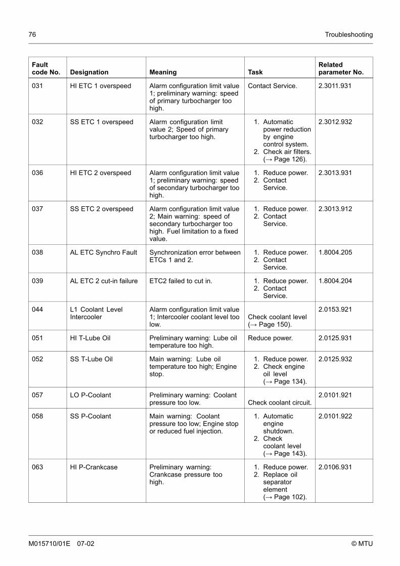
76 Troubleshooting
Faultcode No. Designation Meaning Task
Relatedparameter No.
031 HI ETC 1 overspeed Alarm configuration limit value1; preliminary warning: speedof primary turbocharger toohigh.
Contact Service. 2.3011.931
032 SS ETC 1 overspeed Alarm configuration limitvalue 2; Speed of primaryturbocharger too high.
1. Automaticpower reductionby enginecontrol system.
2. Check air filters.(→ Page 126).
2.3012.932
036 HI ETC 2 overspeed Alarm configuration limit value1; preliminary warning: speedof secondary turbocharger toohigh.
1. Reduce power.2. Contact
Service.
2.3013.931
037 SS ETC 2 overspeed Alarm configuration limit value2; Main warning: speed ofsecondary turbocharger toohigh. Fuel limitation to a fixedvalue.
1. Reduce power.2. Contact
Service.
2.3013.912
038 AL ETC Synchro Fault Synchronization error betweenETCs 1 and 2.
1. Reduce power.2. Contact
Service.
1.8004.205
039 AL ETC 2 cut-in failure ETC2 failed to cut in. 1. Reduce power.2. Contact
Service.
1.8004.204
044 L1 Coolant LevelIntercooler
Alarm configuration limit value1; Intercooler coolant level toolow.
Check coolant level(→ Page 150).
2.0153.921
051 HI T-Lube Oil Preliminary warning: Lube oiltemperature too high.
Reduce power. 2.0125.931
052 SS T-Lube Oil Main warning: Lube oiltemperature too high; Enginestop.
1. Reduce power.2. Check engine
oil level(→ Page 134).
2.0125.932
057 LO P-Coolant Preliminary warning: Coolantpressure too low. Check coolant circuit.
2.0101.921
058 SS P-Coolant Main warning: Coolantpressure too low; Engine stopor reduced fuel injection.
1. Automaticengineshutdown.
2. Checkcoolant level(→ Page 143).
2.0101.922
063 HI P-Crankcase Preliminary warning:Crankcase pressure toohigh.
1. Reduce power.2. Replace oil
separatorelement(→ Page 102).
2.0106.931
M015710/01E 07-02 © MTU
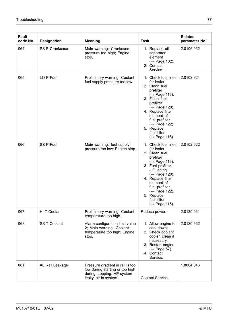
Troubleshooting 77
Faultcode No. Designation Meaning Task
Relatedparameter No.
064 SS P-Crankcase Main warning: Crankcasepressure too high; Enginestop.
1. Replace oilseparatorelement(→ Page 102).
2. ContactService.
2.0106.932
065 LO P-Fuel Preliminary warning: Coolantfuel supply pressure too low.
1. Check fuel linesfor leaks.
2. Clean fuelprefilter(→ Page 116).
3. Flush fuelprefilter(→ Page 120).
4. Replace filterelement offuel prefilter(→ Page 122).
5. Replacefuel filter(→ Page 115).
2.0102.921
066 SS P-Fuel Main warning: fuel supplypressure too low; Engine stop.
1. Check fuel linesfor leaks.
2. Clean fuelprefilter(→ Page 116).
3. Fuel prefilter- Flushing(→ Page 120).
4. Replace filterelement offuel prefilter(→ Page 122).
5. Replacefuel filter(→ Page 115).
2.0102.922
067 HI T-Coolant Preliminary warning: Coolanttemperature too high.
Reduce power. 2.0120.931
068 SS T-Coolant Alarm configuration limit value2; Main warning: Coolanttemperature too high; Enginestop.
1. Allow engine tocool down;
2. Check coolantcooler, clean ifnecessary.
3. Restart engine(→ Page 57).
4. ContactService.
2.0120.932
081 AL Rail Leakage Pressure gradient in rail is toolow during starting or too highduring stopping; HP systemleaky, air in system). Contact Service.
1.8004.046
M015710/01E 07-02 © MTU
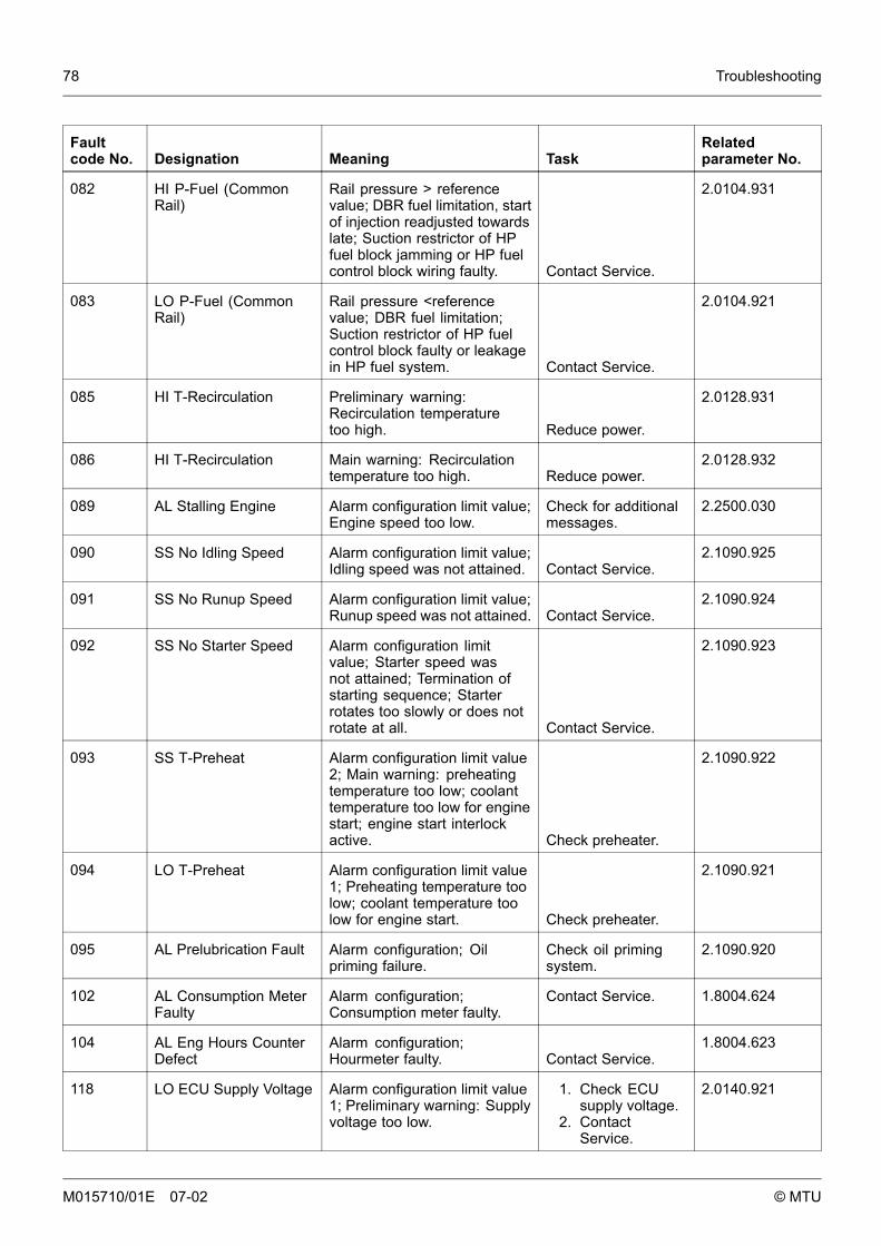
78 Troubleshooting
Faultcode No. Designation Meaning Task
Relatedparameter No.
082 HI P-Fuel (CommonRail)
Rail pressure > referencevalue; DBR fuel limitation, startof injection readjusted towardslate; Suction restrictor of HPfuel block jamming or HP fuelcontrol block wiring faulty. Contact Service.
2.0104.931
083 LO P-Fuel (CommonRail)
Rail pressure <referencevalue; DBR fuel limitation;Suction restrictor of HP fuelcontrol block faulty or leakagein HP fuel system. Contact Service.
2.0104.921
085 HI T-Recirculation Preliminary warning:Recirculation temperaturetoo high. Reduce power.
2.0128.931
086 HI T-Recirculation Main warning: Recirculationtemperature too high. Reduce power.
2.0128.932
089 AL Stalling Engine Alarm configuration limit value;Engine speed too low.
Check for additionalmessages.
2.2500.030
090 SS No Idling Speed Alarm configuration limit value;Idling speed was not attained. Contact Service.
2.1090.925
091 SS No Runup Speed Alarm configuration limit value;Runup speed was not attained. Contact Service.
2.1090.924
092 SS No Starter Speed Alarm configuration limitvalue; Starter speed wasnot attained; Termination ofstarting sequence; Starterrotates too slowly or does notrotate at all. Contact Service.
2.1090.923
093 SS T-Preheat Alarm configuration limit value2; Main warning: preheatingtemperature too low; coolanttemperature too low for enginestart; engine start interlockactive. Check preheater.
2.1090.922
094 LO T-Preheat Alarm configuration limit value1; Preheating temperature toolow; coolant temperature toolow for engine start. Check preheater.
2.1090.921
095 AL Prelubrication Fault Alarm configuration; Oilpriming failure.
Check oil primingsystem.
2.1090.920
102 AL Consumption MeterFaulty
Alarm configuration;Consumption meter faulty.
Contact Service. 1.8004.624
104 AL Eng Hours CounterDefect
Alarm configuration;Hourmeter faulty. Contact Service.
1.8004.623
118 LO ECU Supply Voltage Alarm configuration limit value1; Preliminary warning: Supplyvoltage too low.
1. Check ECUsupply voltage.
2. ContactService.
2.0140.921
M015710/01E 07-02 © MTU
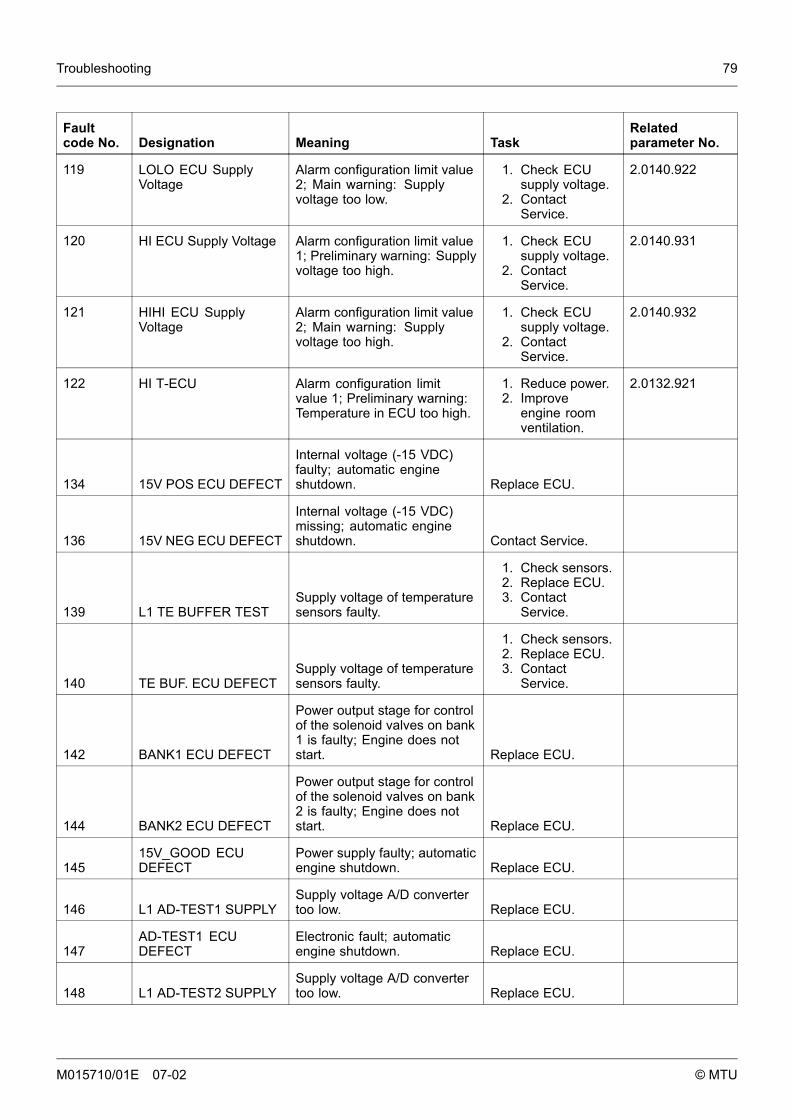
Troubleshooting 79
Faultcode No. Designation Meaning Task
Relatedparameter No.
119 LOLO ECU SupplyVoltage
Alarm configuration limit value2; Main warning: Supplyvoltage too low.
1. Check ECUsupply voltage.
2. ContactService.
2.0140.922
120 HI ECU Supply Voltage Alarm configuration limit value1; Preliminary warning: Supplyvoltage too high.
1. Check ECUsupply voltage.
2. ContactService.
2.0140.931
121 HIHI ECU SupplyVoltage
Alarm configuration limit value2; Main warning: Supplyvoltage too high.
1. Check ECUsupply voltage.
2. ContactService.
2.0140.932
122 HI T-ECU Alarm configuration limitvalue 1; Preliminary warning:Temperature in ECU too high.
1. Reduce power.2. Improve
engine roomventilation.
2.0132.921
134 15V POS ECU DEFECT
Internal voltage (-15 VDC)faulty; automatic engineshutdown. Replace ECU.
136 15V NEG ECU DEFECT
Internal voltage (-15 VDC)missing; automatic engineshutdown. Contact Service.
139 L1 TE BUFFER TESTSupply voltage of temperaturesensors faulty.
1. Check sensors.2. Replace ECU.3. Contact
Service.
140 TE BUF. ECU DEFECTSupply voltage of temperaturesensors faulty.
1. Check sensors.2. Replace ECU.3. Contact
Service.
142 BANK1 ECU DEFECT
Power output stage for controlof the solenoid valves on bank1 is faulty; Engine does notstart. Replace ECU.
144 BANK2 ECU DEFECT
Power output stage for controlof the solenoid valves on bank2 is faulty; Engine does notstart. Replace ECU.
14515V_GOOD ECUDEFECT
Power supply faulty; automaticengine shutdown. Replace ECU.
146 L1 AD-TEST1 SUPPLYSupply voltage A/D convertertoo low. Replace ECU.
147AD-TEST1 ECUDEFECT
Electronic fault; automaticengine shutdown. Replace ECU.
148 L1 AD-TEST2 SUPPLYSupply voltage A/D convertertoo low. Replace ECU.
M015710/01E 07-02 © MTU
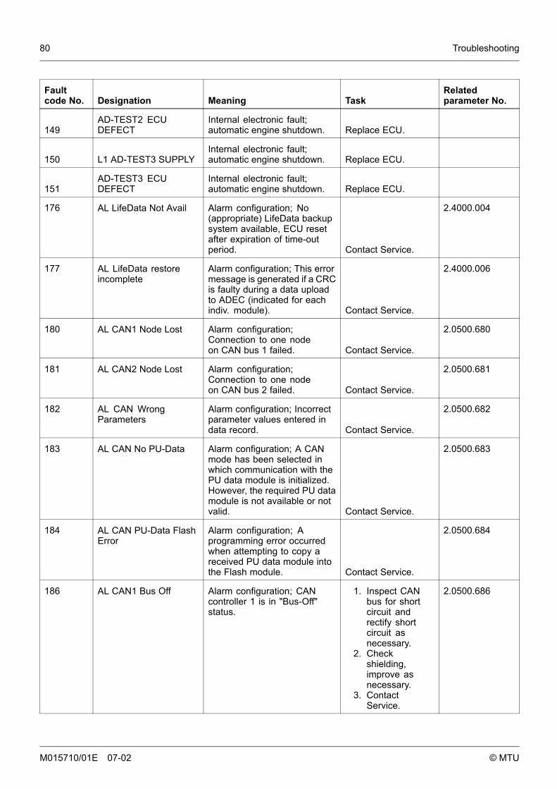
80 Troubleshooting
Faultcode No. Designation Meaning Task
Relatedparameter No.
149AD-TEST2 ECUDEFECT
Internal electronic fault;automatic engine shutdown. Replace ECU.
150 L1 AD-TEST3 SUPPLYInternal electronic fault;automatic engine shutdown. Replace ECU.
151AD-TEST3 ECUDEFECT
Internal electronic fault;automatic engine shutdown. Replace ECU.
176 AL LifeData Not Avail Alarm configuration; No(appropriate) LifeData backupsystem available, ECU resetafter expiration of time-outperiod. Contact Service.
2.4000.004
177 AL LifeData restoreincomplete
Alarm configuration; This errormessage is generated if a CRCis faulty during a data uploadto ADEC (indicated for eachindiv. module). Contact Service.
2.4000.006
180 AL CAN1 Node Lost Alarm configuration;Connection to one nodeon CAN bus 1 failed. Contact Service.
2.0500.680
181 AL CAN2 Node Lost Alarm configuration;Connection to one nodeon CAN bus 2 failed. Contact Service.
2.0500.681
182 AL CAN WrongParameters
Alarm configuration; Incorrectparameter values entered indata record. Contact Service.
2.0500.682
183 AL CAN No PU-Data Alarm configuration; A CANmode has been selected inwhich communication with thePU data module is initialized.However, the required PU datamodule is not available or notvalid. Contact Service.
2.0500.683
184 AL CAN PU-Data FlashError
Alarm configuration; Aprogramming error occurredwhen attempting to copy areceived PU data module intothe Flash module. Contact Service.
2.0500.684
186 AL CAN1 Bus Off Alarm configuration; CANcontroller 1 is in "Bus-Off"status.
1. Inspect CANbus for shortcircuit andrectify shortcircuit asnecessary.
2. Checkshielding,improve asnecessary.
3. ContactService.
2.0500.686
M015710/01E 07-02 © MTU
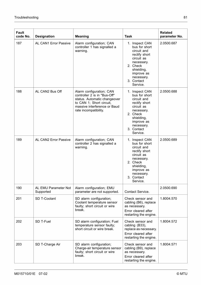
Troubleshooting 81
Faultcode No. Designation Meaning Task
Relatedparameter No.
187 AL CAN1 Error Passive Alarm configuration; CANcontroller 1 has signalled awarning.
1. Inspect CANbus for shortcircuit andrectify shortcircuit asnecessary.
2. Checkshielding,improve asnecessary.
3. ContactService.
2.0500.687
188 AL CAN2 Bus Off Alarm configuration; CANcontroller 2 is in "Bus-Off"status. Automatic changeoverto CAN 1; Short circuit,massive interference or Baudrate incompatibility.
1. Inspect CANbus for shortcircuit andrectify shortcircuit asnecessary.
2. Checkshielding,improve asnecessary.
3. ContactService.
2.0500.688
189 AL CAN2 Error Passive Alarm configuration; CANcontroller 2 has signalled awarning.
1. Inspect CANbus for shortcircuit andrectify shortcircuit asnecessary.
2. Checkshielding,improve asnecessary.
3. ContactService.
2.0500.689
190 AL EMU Parameter NotSupported
Alarm configuration; EMUparameter are not supported. Contact Service.
2.0500.690
201 SD T-Coolant SD alarm configuration;Coolant temperature sensorfaulty; short circuit or wirebreak.
Check sensor andcabling (B6), replaceas necessary.Error cleared afterrestarting the engine.
1.8004.570
202 SD T-Fuel SD alarm configuration; Fueltemperature sensor faulty;short circuit or wire break.
Check sensor andcabling (B33),replace as necessary.Error cleared afterrestarting the engine.
1.8004.572
203 SD T-Charge Air SD alarm configuration;Charge-air temperature sensorfaulty; short circuit or wirebreak.
Check sensor andcabling (B9), replaceas necessary.Error cleared afterrestarting the engine.
1.8004.571
M015710/01E 07-02 © MTU
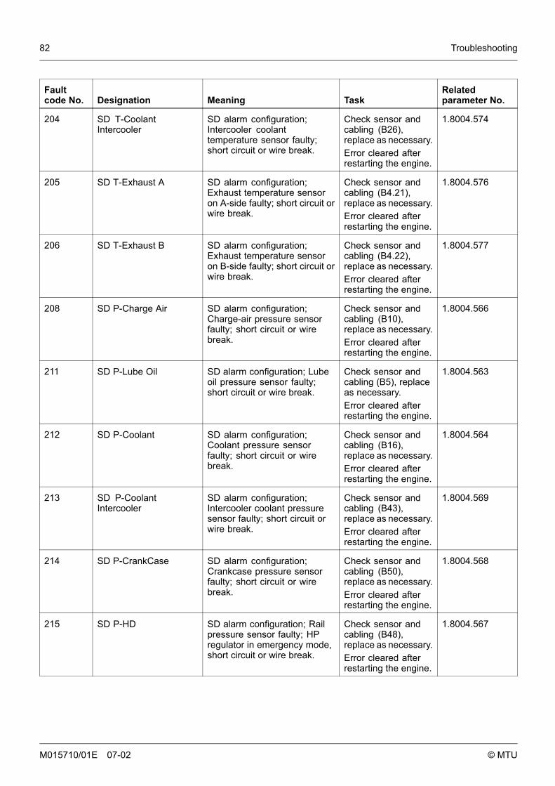
82 Troubleshooting
Faultcode No. Designation Meaning Task
Relatedparameter No.
204 SD T-CoolantIntercooler
SD alarm configuration;Intercooler coolanttemperature sensor faulty;short circuit or wire break.
Check sensor andcabling (B26),replace as necessary.Error cleared afterrestarting the engine.
1.8004.574
205 SD T-Exhaust A SD alarm configuration;Exhaust temperature sensoron A-side faulty; short circuit orwire break.
Check sensor andcabling (B4.21),replace as necessary.Error cleared afterrestarting the engine.
1.8004.576
206 SD T-Exhaust B SD alarm configuration;Exhaust temperature sensoron B-side faulty; short circuit orwire break.
Check sensor andcabling (B4.22),replace as necessary.Error cleared afterrestarting the engine.
1.8004.577
208 SD P-Charge Air SD alarm configuration;Charge-air pressure sensorfaulty; short circuit or wirebreak.
Check sensor andcabling (B10),replace as necessary.Error cleared afterrestarting the engine.
1.8004.566
211 SD P-Lube Oil SD alarm configuration; Lubeoil pressure sensor faulty;short circuit or wire break.
Check sensor andcabling (B5), replaceas necessary.Error cleared afterrestarting the engine.
1.8004.563
212 SD P-Coolant SD alarm configuration;Coolant pressure sensorfaulty; short circuit or wirebreak.
Check sensor andcabling (B16),replace as necessary.Error cleared afterrestarting the engine.
1.8004.564
213 SD P-CoolantIntercooler
SD alarm configuration;Intercooler coolant pressuresensor faulty; short circuit orwire break.
Check sensor andcabling (B43),replace as necessary.Error cleared afterrestarting the engine.
1.8004.569
214 SD P-CrankCase SD alarm configuration;Crankcase pressure sensorfaulty; short circuit or wirebreak.
Check sensor andcabling (B50),replace as necessary.Error cleared afterrestarting the engine.
1.8004.568
215 SD P-HD SD alarm configuration; Railpressure sensor faulty; HPregulator in emergency mode,short circuit or wire break.
Check sensor andcabling (B48),replace as necessary.Error cleared afterrestarting the engine.
1.8004.567
M015710/01E 07-02 © MTU
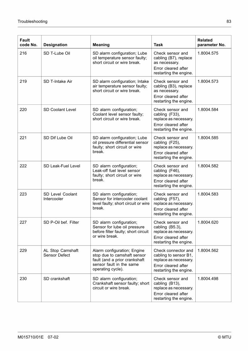
Troubleshooting 83
Faultcode No. Designation Meaning Task
Relatedparameter No.
216 SD T-Lube Oil SD alarm configuration; Lubeoil temperature sensor faulty;short circuit or wire break.
Check sensor andcabling (B7), replaceas necessary.Error cleared afterrestarting the engine.
1.8004.575
219 SD T-Intake Air SD alarm configuration; Intakeair temperature sensor faulty;short circuit or wire break.
Check sensor andcabling (B3), replaceas necessary.Error cleared afterrestarting the engine.
1.8004.573
220 SD Coolant Level SD alarm configuration;Coolant level sensor faulty;short circuit or wire break.
Check sensor andcabling (F33),replace as necessary.Error cleared afterrestarting the engine.
1.8004.584
221 SD Dif Lube Oil SD alarm configuration; Lubeoil pressure differential sensorfaulty; short circuit or wirebreak.
Check sensor andcabling (F25),replace as necessary.Error cleared afterrestarting the engine.
1.8004.585
222 SD Leak-Fuel Level SD alarm configuration;Leak-off fuel level sensorfaulty; short circuit or wirebreak.
Check sensor andcabling (F46),replace as necessary.Error cleared afterrestarting the engine.
1.8004.582
223 SD Level CoolantIntercooler
SD alarm configuration;Sensor for intercooler coolantlevel faulty; short circuit or wirebreak.
Check sensor andcabling (F57),replace as necessary.Error cleared afterrestarting the engine.
1.8004.583
227 SD P-Oil bef. Filter SD alarm configuration;Sensor for lube oil pressurebefore filter faulty; short circuitor wire break.
Check sensor andcabling (B5.3),replace as necessary.Error cleared afterrestarting the engine.
1.8004.620
229 AL Stop CamshaftSensor Defect
Alarm configuration; Enginestop due to camshaft sensorfault (and a prior crankshaftsensor fault in the sameoperating cycle).
Check connector andcabling to sensor B1,replace as necessary.Error cleared afterrestarting the engine.
1.8004.562
230 SD crankshaft SD alarm configuration;Crankshaft sensor faulty; shortcircuit or wire break.
Check sensor andcabling (B13),replace as necessary.Error cleared afterrestarting the engine.
1.8004.498
M015710/01E 07-02 © MTU
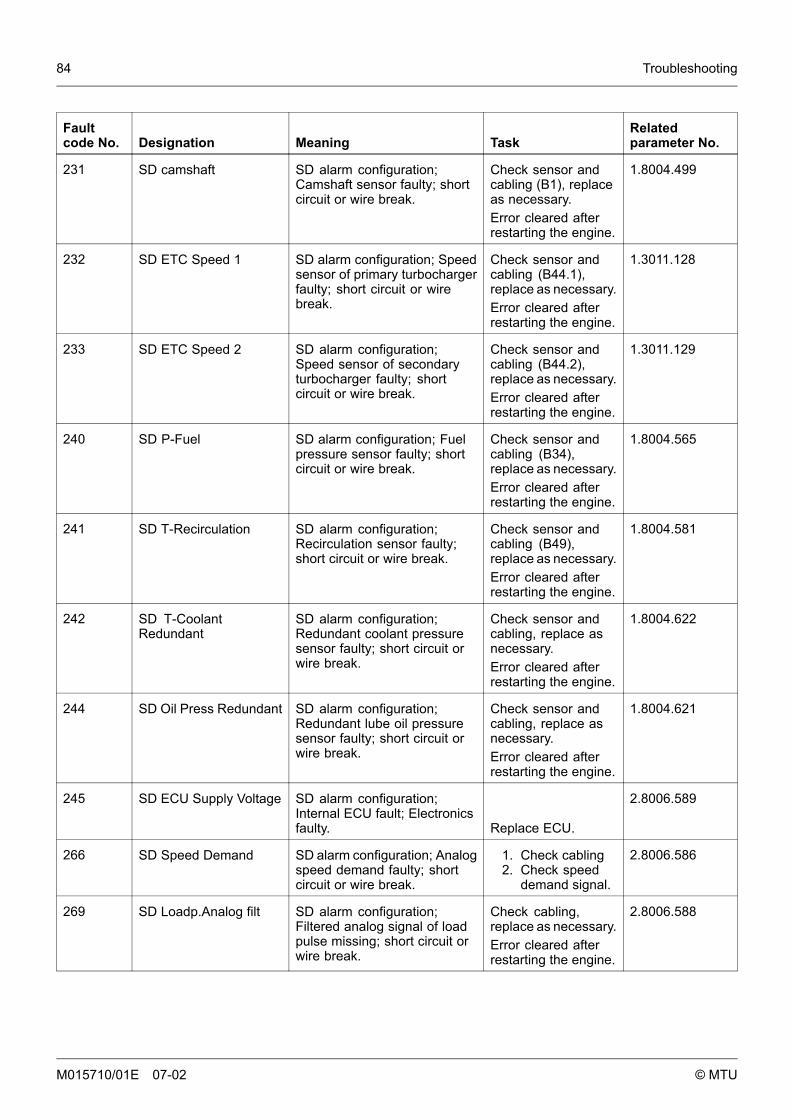
84 Troubleshooting
Faultcode No. Designation Meaning Task
Relatedparameter No.
231 SD camshaft SD alarm configuration;Camshaft sensor faulty; shortcircuit or wire break.
Check sensor andcabling (B1), replaceas necessary.Error cleared afterrestarting the engine.
1.8004.499
232 SD ETC Speed 1 SD alarm configuration; Speedsensor of primary turbochargerfaulty; short circuit or wirebreak.
Check sensor andcabling (B44.1),replace as necessary.Error cleared afterrestarting the engine.
1.3011.128
233 SD ETC Speed 2 SD alarm configuration;Speed sensor of secondaryturbocharger faulty; shortcircuit or wire break.
Check sensor andcabling (B44.2),replace as necessary.Error cleared afterrestarting the engine.
1.3011.129
240 SD P-Fuel SD alarm configuration; Fuelpressure sensor faulty; shortcircuit or wire break.
Check sensor andcabling (B34),replace as necessary.Error cleared afterrestarting the engine.
1.8004.565
241 SD T-Recirculation SD alarm configuration;Recirculation sensor faulty;short circuit or wire break.
Check sensor andcabling (B49),replace as necessary.Error cleared afterrestarting the engine.
1.8004.581
242 SD T-CoolantRedundant
SD alarm configuration;Redundant coolant pressuresensor faulty; short circuit orwire break.
Check sensor andcabling, replace asnecessary.Error cleared afterrestarting the engine.
1.8004.622
244 SD Oil Press Redundant SD alarm configuration;Redundant lube oil pressuresensor faulty; short circuit orwire break.
Check sensor andcabling, replace asnecessary.Error cleared afterrestarting the engine.
1.8004.621
245 SD ECU Supply Voltage SD alarm configuration;Internal ECU fault; Electronicsfaulty. Replace ECU.
2.8006.589
266 SD Speed Demand SD alarm configuration; Analogspeed demand faulty; shortcircuit or wire break.
1. Check cabling2. Check speed
demand signal.
2.8006.586
269 SD Loadp.Analog filt SD alarm configuration;Filtered analog signal of loadpulse missing; short circuit orwire break.
Check cabling,replace as necessary.Error cleared afterrestarting the engine.
2.8006.588
M015710/01E 07-02 © MTU
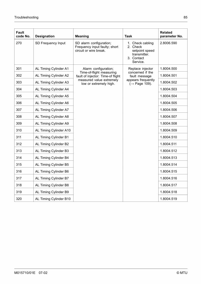
Troubleshooting 85
Faultcode No. Designation Meaning Task
Relatedparameter No.
270 SD Frequency Input SD alarm configuration;Frequency input faulty; shortcircuit or wire break.
1. Check cabling2. Check
setpoint speedtransmitter.
3. ContactService.
2.8006.590
301 AL Timing Cylinder A1 1.8004.500
302 AL Timing Cylinder A2 1.8004.501
303 AL Timing Cylinder A3 1.8004.502
304 AL Timing Cylinder A4 1.8004.503
305 AL Timing Cylinder A5 1.8004.504
306 AL Timing Cylinder A6 1.8004.505
307 AL Timing Cylinder A7 1.8004.506
308 AL Timing Cylinder A8 1.8004.507
309 AL Timing Cylinder A9 1.8004.508
310 AL Timing Cylinder A10 1.8004.509
311 AL Timing Cylinder B1 1.8004.510
312 AL Timing Cylinder B2 1.8004.511
313 AL Timing Cylinder B3 1.8004.512
314 AL Timing Cylinder B4 1.8004.513
315 AL Timing Cylinder B5 1.8004.514
316 AL Timing Cylinder B6 1.8004.515
317 AL Timing Cylinder B7 1.8004.516
318 AL Timing Cylinder B8 1.8004.517
319 AL Timing Cylinder B9 1.8004.518
320 AL Timing Cylinder B10
Alarm configuration;Time-of-flight measuring
fault of injector: Time-of flightmeasured value extremely
low or extremely high.
Replace injectorconcerned if thefault message
appears frequently(→ Page 109).
1.8004.519
M015710/01E 07-02 © MTU
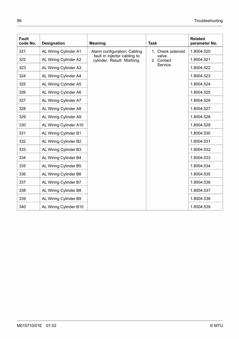
86 Troubleshooting
Faultcode No. Designation Meaning Task
Relatedparameter No.
321 AL Wiring Cylinder A1 1.8004.520
322 AL Wiring Cylinder A2 1.8004.521
323 AL Wiring Cylinder A3 1.8004.522
324 AL Wiring Cylinder A4 1.8004.523
325 AL Wiring Cylinder A5 1.8004.524
326 AL Wiring Cylinder A6 1.8004.525
327 AL Wiring Cylinder A7 1.8004.526
328 AL Wiring Cylinder A8 1.8004.527
329 AL Wiring Cylinder A9 1.8004.528
330 AL Wiring Cylinder A10 1.8004.529
331 AL Wiring Cylinder B1 1.8004.530
332 AL Wiring Cylinder B2 1.8004.531
333 AL Wiring Cylinder B3 1.8004.532
334 AL Wiring Cylinder B4 1.8004.533
335 AL Wiring Cylinder B5 1.8004.534
336 AL Wiring Cylinder B6 1.8004.535
337 AL Wiring Cylinder B7 1.8004.536
338 AL Wiring Cylinder B8 1.8004.537
339 AL Wiring Cylinder B9 1.8004.538
340 AL Wiring Cylinder B10
Alarm configuration; Cablingfault in injector cabling tocylinder. Result: Misfiring.
1. Check solenoidvalve.
2. ContactService.
1.8004.539
M015710/01E 07-02 © MTU
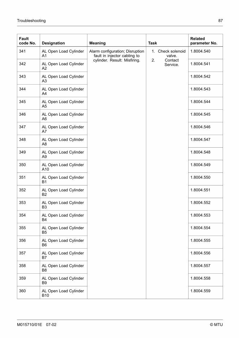
Troubleshooting 87
Faultcode No. Designation Meaning Task
Relatedparameter No.
341 AL Open Load CylinderA1
1.8004.540
342 AL Open Load CylinderA2
1.8004.541
343 AL Open Load CylinderA3
1.8004.542
344 AL Open Load CylinderA4
1.8004.543
345 AL Open Load CylinderA5
1.8004.544
346 AL Open Load CylinderA6
1.8004.545
347 AL Open Load CylinderA7
1.8004.546
348 AL Open Load CylinderA8
1.8004.547
349 AL Open Load CylinderA9
1.8004.548
350 AL Open Load CylinderA10
1.8004.549
351 AL Open Load CylinderB1
1.8004.550
352 AL Open Load CylinderB2
1.8004.551
353 AL Open Load CylinderB3
1.8004.552
354 AL Open Load CylinderB4
1.8004.553
355 AL Open Load CylinderB5
1.8004.554
356 AL Open Load CylinderB6
1.8004.555
357 AL Open Load CylinderB7
1.8004.556
358 AL Open Load CylinderB8
1.8004.557
359 AL Open Load CylinderB9
1.8004.558
360 AL Open Load CylinderB10
Alarm configuration; Disruptionfault in injector cabling tocylinder. Result: Misfiring.
1. Check solenoidvalve.
2. ContactService.
1.8004.559
M015710/01E 07-02 © MTU
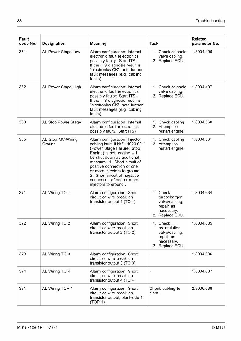
88 Troubleshooting
Faultcode No. Designation Meaning Task
Relatedparameter No.
361 AL Power Stage Low Alarm configuration; Internalelectronic fault (electronicspossibly faulty: Start ITS).If the ITS diagnosis result is"electronics OK", note furtherfault messages (e.g. cablingfaults).
1. Check solenoidvalve cabling.
2. Replace ECU.
1.8004.496
362 AL Power Stage High Alarm configuration; Internalelectronic fault (electronicspossibly faulty: Start ITS).If the ITS diagnosis result is"electronics OK", note furtherfault messages (e.g. cablingfaults).
1. Check solenoidvalve cabling.
2. Replace ECU.
1.8004.497
363 AL Stop Power Stage Alarm configuration; Internalelectronic fault (electronicspossibly faulty: Start ITS).
1. Check cabling2. Attempt to
restart engine.
1.8004.560
365 AL Stop MV-WiringGround
Alarm configuration; Injectorcabling fault. If bit "1.1020.021"(Power Stage Failure: StopEngine) is set, engine willbe shut down as additionalmeasure. 1. Short circuit ofpositive connection of oneor more injectors to ground2. Short circuit of negativeconnection of one or moreinjectors to ground .
1. Check cabling2. Attempt to
restart engine.
1.8004.561
371 AL Wiring TO 1 Alarm configuration; Shortcircuit or wire break ontransistor output 1 (TO 1).
1. Checkturbochargervalve/cabling,repair asnecessary.
2. Replace ECU.
1.8004.634
372 AL Wiring TO 2 Alarm configuration; Shortcircuit or wire break ontransistor output 2 (TO 2).
1. Checkrecirculationvalve/cabling,repair asnecessary.
2. Replace ECU.
1.8004.635
373 AL Wiring TO 3 Alarm configuration; Shortcircuit or wire break ontransistor output 3 (TO 3).
- 1.8004.636
374 AL Wiring TO 4 Alarm configuration; Shortcircuit or wire break ontransistor output 4 (TO 4).
- 1.8004.637
381 AL Wiring TOP 1 Alarm configuration; Shortcircuit or wire break ontransistor output, plant-side 1(TOP 1).
Check cabling toplant.
2.8006.638
M015710/01E 07-02 © MTU

Troubleshooting 89
Faultcode No. Designation Meaning Task
Relatedparameter No.
382 AL Wiring TOP 2 Alarm configuration; Shortcircuit or wire break ontransistor output, plant-side 2(TOP 2).
Check cabling toplant.
2.8006.639
383 AL Wiring TOP 3 Alarm configuration; Shortcircuit or wire break ontransistor output, plant-side 3(TOP 3).
Check cabling toplant.
2.8006.640
384 AL Wiring TOP 4 Alarm configuration; Shortcircuit or wire break ontransistor output, plant-side 4(TOP 4).
Check cabling toplant.
2.8006.641
390 AL MCR exceeded Alarm configuration;DBR/MCR function: MCRhas been exceeded.
1. If alarm is onlytemporary, noaction required;
2. if alarm iscontinuouslyactive, contactService.
1.1085.009
392 HI T-Coolant Redundant Alarm configuration limitvalue 1; Preliminarywarning: Redundant coolanttemperature reading too high.
1. Check cabling2. Contact
Service.
2.0129.931
393 SS T-CoolantRedundant
Alarm configuration limit value1; Main warning: Redundantcoolant temperature readingtoo high; Engine stop.
1. Check cablingand sensor.
2. ContactService.
2.0129.932
394 LO P-Lube OilRedundant
Alarm configuration limitvalue 1; Preliminary warning:Redundant lube oil pressurereading too low.
1. Check cablingand sensor.
2. ContactService.
2.0112.921
395 SS P-Lube OilRedundant
Alarm configuration limit value2; Main warning: Redundantlube oil pressure reading toolow.
1. Check cablingand sensor.
2. ContactService.
2.0112.922
396 AL T-Coolant MaxDeviation
Alarm configuration; Maximumcoolant temperature deviation.
1. Check cablingand sensor.
2. ContactService.
1.8004.626
397 AL P-Oil Max Deviation Alarm configuration; Maximumlube oil pressure deviation.
1. Check cablingand sensor.
2. ContactService.
1.8004.625
400 AL Open Load DigitalInput 1
Alarm configuration; Linedisruption on digital input 1;Cabling faulty or no resistanceover switch.
1. Check cabling2. Check input of
target device.3. Contact
Service.
2.8006.625
M015710/01E 07-02 © MTU
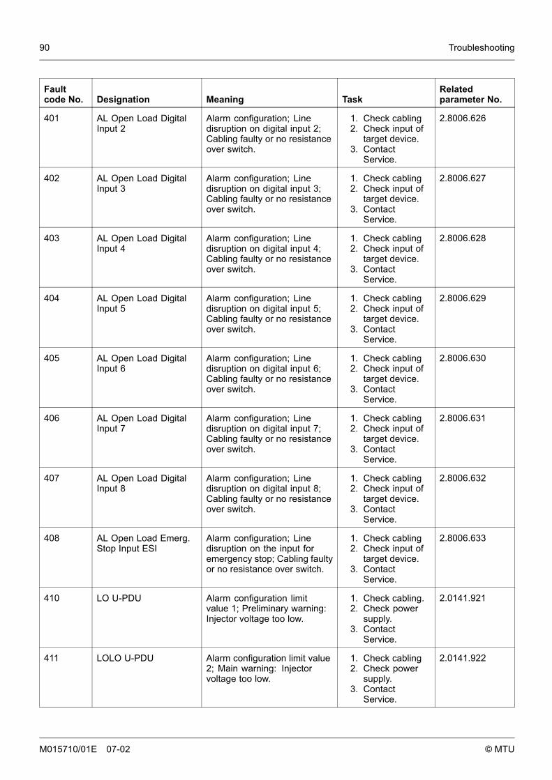
90 Troubleshooting
Faultcode No. Designation Meaning Task
Relatedparameter No.
401 AL Open Load DigitalInput 2
Alarm configuration; Linedisruption on digital input 2;Cabling faulty or no resistanceover switch.
1. Check cabling2. Check input of
target device.3. Contact
Service.
2.8006.626
402 AL Open Load DigitalInput 3
Alarm configuration; Linedisruption on digital input 3;Cabling faulty or no resistanceover switch.
1. Check cabling2. Check input of
target device.3. Contact
Service.
2.8006.627
403 AL Open Load DigitalInput 4
Alarm configuration; Linedisruption on digital input 4;Cabling faulty or no resistanceover switch.
1. Check cabling2. Check input of
target device.3. Contact
Service.
2.8006.628
404 AL Open Load DigitalInput 5
Alarm configuration; Linedisruption on digital input 5;Cabling faulty or no resistanceover switch.
1. Check cabling2. Check input of
target device.3. Contact
Service.
2.8006.629
405 AL Open Load DigitalInput 6
Alarm configuration; Linedisruption on digital input 6;Cabling faulty or no resistanceover switch.
1. Check cabling2. Check input of
target device.3. Contact
Service.
2.8006.630
406 AL Open Load DigitalInput 7
Alarm configuration; Linedisruption on digital input 7;Cabling faulty or no resistanceover switch.
1. Check cabling2. Check input of
target device.3. Contact
Service.
2.8006.631
407 AL Open Load DigitalInput 8
Alarm configuration; Linedisruption on digital input 8;Cabling faulty or no resistanceover switch.
1. Check cabling2. Check input of
target device.3. Contact
Service.
2.8006.632
408 AL Open Load Emerg.Stop Input ESI
Alarm configuration; Linedisruption on the input foremergency stop; Cabling faultyor no resistance over switch.
1. Check cabling2. Check input of
target device.3. Contact
Service.
2.8006.633
410 LO U-PDU Alarm configuration limitvalue 1; Preliminary warning:Injector voltage too low.
1. Check cabling.2. Check power
supply.3. Contact
Service.
2.0141.921
411 LOLO U-PDU Alarm configuration limit value2; Main warning: Injectorvoltage too low.
1. Check cabling2. Check power
supply.3. Contact
Service.
2.0141.922
M015710/01E 07-02 © MTU
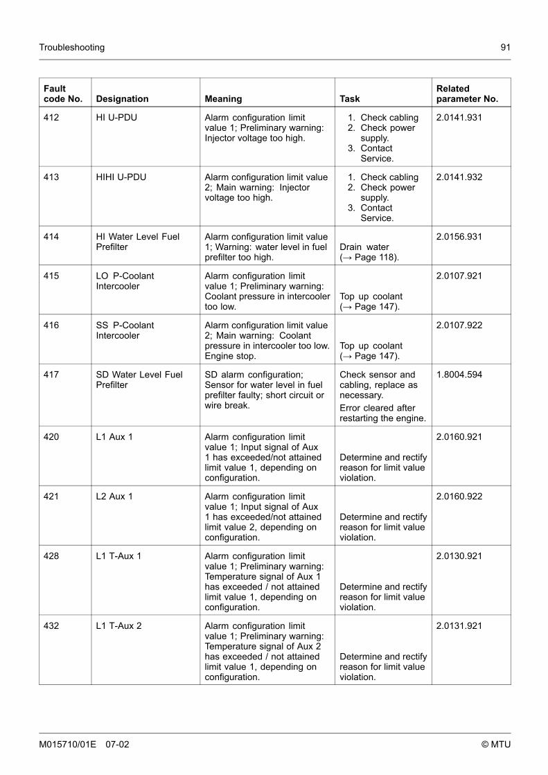
Troubleshooting 91
Faultcode No. Designation Meaning Task
Relatedparameter No.
412 HI U-PDU Alarm configuration limitvalue 1; Preliminary warning:Injector voltage too high.
1. Check cabling2. Check power
supply.3. Contact
Service.
2.0141.931
413 HIHI U-PDU Alarm configuration limit value2; Main warning: Injectorvoltage too high.
1. Check cabling2. Check power
supply.3. Contact
Service.
2.0141.932
414 HI Water Level FuelPrefilter
Alarm configuration limit value1; Warning: water level in fuelprefilter too high.
Drain water(→ Page 118).
2.0156.931
415 LO P-CoolantIntercooler
Alarm configuration limitvalue 1; Preliminary warning:Coolant pressure in intercoolertoo low.
Top up coolant(→ Page 147).
2.0107.921
416 SS P-CoolantIntercooler
Alarm configuration limit value2; Main warning: Coolantpressure in intercooler too low.Engine stop.
Top up coolant(→ Page 147).
2.0107.922
417 SD Water Level FuelPrefilter
SD alarm configuration;Sensor for water level in fuelprefilter faulty; short circuit orwire break.
Check sensor andcabling, replace asnecessary.Error cleared afterrestarting the engine.
1.8004.594
420 L1 Aux 1 Alarm configuration limitvalue 1; Input signal of Aux1 has exceeded/not attainedlimit value 1, depending onconfiguration.
Determine and rectifyreason for limit valueviolation.
2.0160.921
421 L2 Aux 1 Alarm configuration limitvalue 1; Input signal of Aux1 has exceeded/not attainedlimit value 2, depending onconfiguration.
Determine and rectifyreason for limit valueviolation.
2.0160.922
428 L1 T-Aux 1 Alarm configuration limitvalue 1; Preliminary warning:Temperature signal of Aux 1has exceeded / not attainedlimit value 1, depending onconfiguration.
Determine and rectifyreason for limit valueviolation.
2.0130.921
432 L1 T-Aux 2 Alarm configuration limitvalue 1; Preliminary warning:Temperature signal of Aux 2has exceeded / not attainedlimit value 1, depending onconfiguration.
Determine and rectifyreason for limit valueviolation.
2.0131.921
M015710/01E 07-02 © MTU

92 Troubleshooting
Faultcode No. Designation Meaning Task
Relatedparameter No.
433 L2 T-Aux 2 Alarm configuration limitvalue 2; Preliminary warning:Temperature signal of Aux 2has exceeded / not attainedlimit value 2, depending onconfiguration.
Determine and rectifyreason for limit valueviolation.
2.0131.922
436 L1 P-Aux 2 Alarm configuration limitvalue 1; Preliminary warning:Pressure signal of Aux 2has exceeded / not attainedlimit value 1, depending onconfiguration.
Determine and rectifyreason for limit valueviolation.
2.0111.921
437 L2 P-Aux 2 Alarm configuration limitvalue 2; Preliminary warning:Pressure signal of Aux 2has exceeded / not attainedlimit value 2, depending onconfiguration.
Determine and rectifyreason for limit valueviolation.
2.0111.922
440 L1 P-Aux 1 Alarm configuration limitvalue 1; Preliminary warning:Pressure signal of Aux 1has exceeded / not attainedlimit value 1, depending onconfiguration.
Determine and rectifyreason for limit valueviolation.
2.0110.921
442 L2 P-Aux 1 Alarm configuration limitvalue 2; Preliminary warning:Pressure signal of Aux 1has exceeded / not attainedlimit value 2, depending onconfiguration.
Determine and rectifyreason for limit valueviolation.
2.0110.931
444 SD U-PDU SD alarm configuration;Injector power stage sensordefect; Internal fault in ECU. Replace ECU.
1.8004.578
445 SD P-Ambient Air SD alarm configuration;Ambient air pressure sensorfaulty. Replace ECU.
1.8004.580
448 HI P-Charge Air Alarm configuration limitvalue 1; Preliminary warning:Charge-air pressure too high. Contact Service.
2.0103.931
449 SS P-Charge Air Alarm configuration limit value2; Main warning: Charge-airpressure too high. Contact Service.
2.0103.932
450 SD Idle/End-TorqueInput [%]
SD alarm configuration; Inputsignal for initial/final torquefaulty; short circuit or wirebreak.
Check signaltransmitter andcabling, replace asnecessary.Error cleared afterrestarting the engine.
2.8006.592
M015710/01E 07-02 © MTU
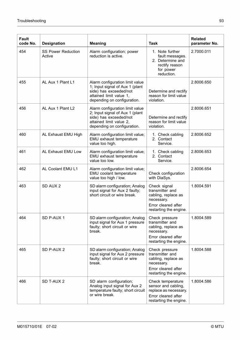
Troubleshooting 93
Faultcode No. Designation Meaning Task
Relatedparameter No.
454 SS Power ReductionActive
Alarm configuration; powerreduction is active.
1. Note furtherfault messages.
2. Determine andrectify reasonfor powerreduction.
2.7000.011
455 AL Aux 1 Plant L1 Alarm configuration limit value1; Input signal of Aux 1 (plantside) has exceeded/notattained limit value 1,depending on configuration.
Determine and rectifyreason for limit valueviolation.
2.8006.650
456 AL Aux 1 Plant L2 Alarm configuration limit value2; Input signal of Aux 1 (plantside) has exceeded/notattained limit value 2,depending on configuration.
Determine and rectifyreason for limit valueviolation.
2.8006.651
460 AL Exhaust EMU High Alarm configuration limit value;EMU exhaust temperaturevalue too high.
1. Check cabling2. Contact
Service.
2.8006.652
461 AL Exhaust EMU Low Alarm configuration limit value;EMU exhaust temperaturevalue too low.
1. Check cabling2. Contact
Service.
2.8006.653
462 AL Coolant EMU L1 Alarm configuration limit value;EMU coolant temperaturevalue too high / low.
Check configurationwith DiaSys.
2.8006.654
463 SD AUX 2 SD alarm configuration; Analoginput signal for Aux 2 faulty;short circuit or wire break.
Check signaltransmitter andcabling, replace asnecessary.Error cleared afterrestarting the engine.
1.8004.591
464 SD P-AUX 1 SD alarm configuration; Analoginput signal for Aux 1 pressurefaulty; short circuit or wirebreak.
Check pressuretransmitter andcabling, replace asnecessary.Error cleared afterrestarting the engine.
1.8004.589
465 SD P-AUX 2 SD alarm configuration; Analoginput signal for Aux 2 pressurefaulty; short circuit or wirebreak.
Check pressuretransmitter andcabling, replace asnecessary.Error cleared afterrestarting the engine.
1.8004.588
466 SD T-AUX 2 SD alarm configuration;Analog input signal for Aux 2temperature faulty; short circuitor wire break.
Check temperaturesensor and cabling,replace as necessary.Error cleared afterrestarting the engine.
1.8004.586
M015710/01E 07-02 © MTU
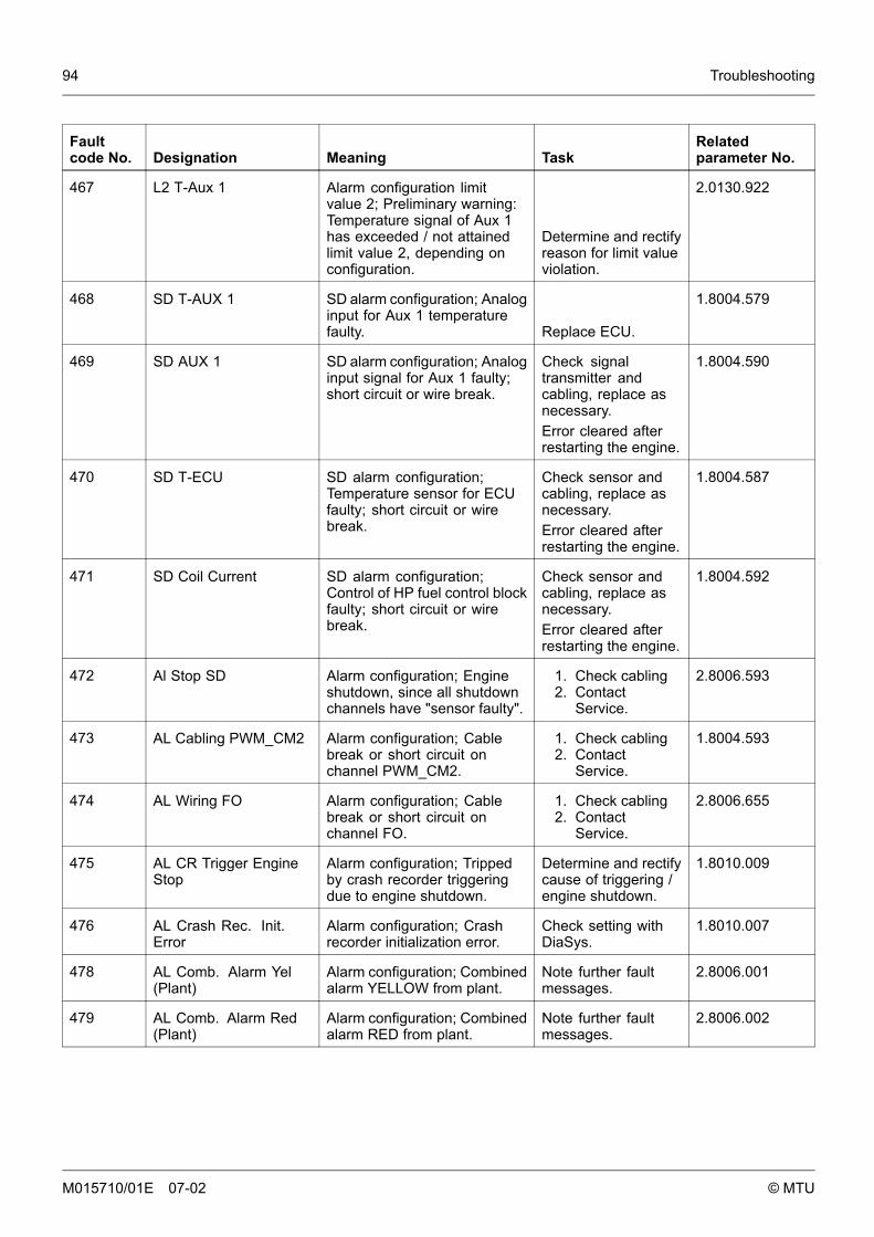
94 Troubleshooting
Faultcode No. Designation Meaning Task
Relatedparameter No.
467 L2 T-Aux 1 Alarm configuration limitvalue 2; Preliminary warning:Temperature signal of Aux 1has exceeded / not attainedlimit value 2, depending onconfiguration.
Determine and rectifyreason for limit valueviolation.
2.0130.922
468 SD T-AUX 1 SD alarm configuration; Analoginput for Aux 1 temperaturefaulty. Replace ECU.
1.8004.579
469 SD AUX 1 SD alarm configuration; Analoginput signal for Aux 1 faulty;short circuit or wire break.
Check signaltransmitter andcabling, replace asnecessary.Error cleared afterrestarting the engine.
1.8004.590
470 SD T-ECU SD alarm configuration;Temperature sensor for ECUfaulty; short circuit or wirebreak.
Check sensor andcabling, replace asnecessary.Error cleared afterrestarting the engine.
1.8004.587
471 SD Coil Current SD alarm configuration;Control of HP fuel control blockfaulty; short circuit or wirebreak.
Check sensor andcabling, replace asnecessary.Error cleared afterrestarting the engine.
1.8004.592
472 Al Stop SD Alarm configuration; Engineshutdown, since all shutdownchannels have "sensor faulty".
1. Check cabling2. Contact
Service.
2.8006.593
473 AL Cabling PWM_CM2 Alarm configuration; Cablebreak or short circuit onchannel PWM_CM2.
1. Check cabling2. Contact
Service.
1.8004.593
474 AL Wiring FO Alarm configuration; Cablebreak or short circuit onchannel FO.
1. Check cabling2. Contact
Service.
2.8006.655
475 AL CR Trigger EngineStop
Alarm configuration; Trippedby crash recorder triggeringdue to engine shutdown.
Determine and rectifycause of triggering /engine shutdown.
1.8010.009
476 AL Crash Rec. Init.Error
Alarm configuration; Crashrecorder initialization error.
Check setting withDiaSys.
1.8010.007
478 AL Comb. Alarm Yel(Plant)
Alarm configuration; Combinedalarm YELLOW from plant.
Note further faultmessages.
2.8006.001
479 AL Comb. Alarm Red(Plant)
Alarm configuration; Combinedalarm RED from plant.
Note further faultmessages.
2.8006.002
M015710/01E 07-02 © MTU
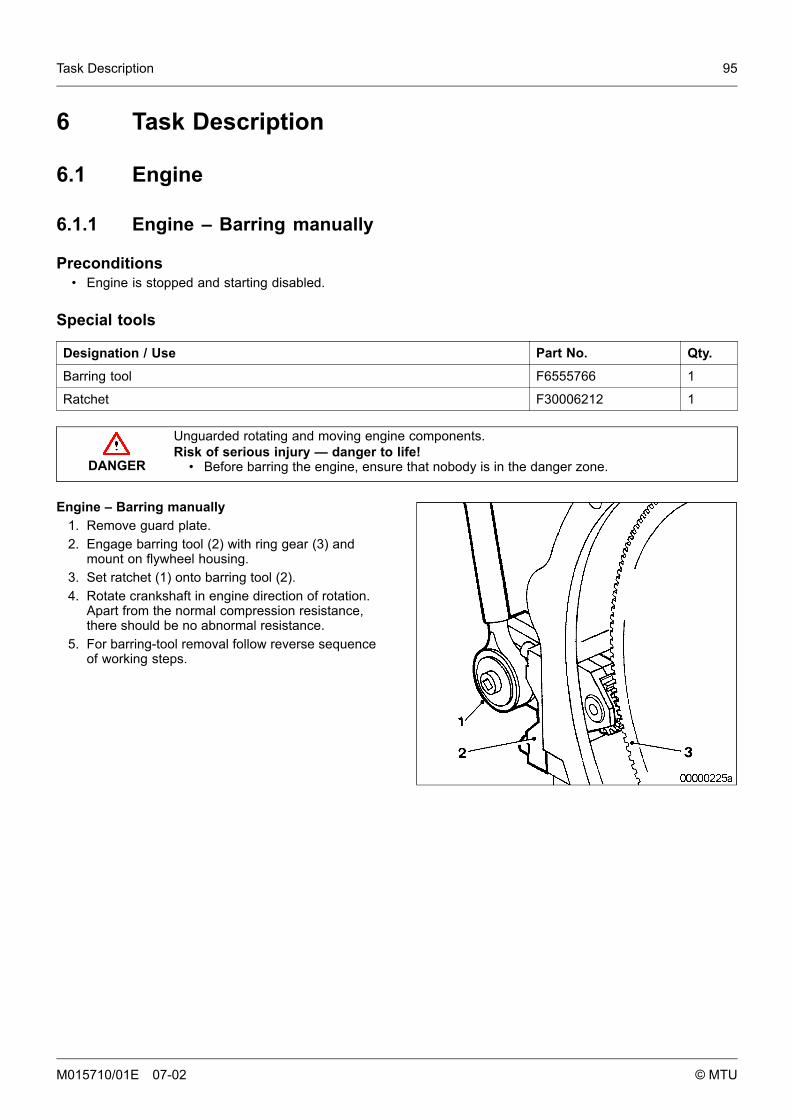
Task Description 95
6 Task Description
6.1 Engine
6.1.1 Engine – Barring manually
Preconditions• Engine is stopped and starting disabled.
Special tools
Designation / Use Part No. Qty.
Barring tool F6555766 1
Ratchet F30006212 1
DANGER
Unguarded rotating and moving engine components.Risk of serious injury — danger to life!
• Before barring the engine, ensure that nobody is in the danger zone.
Engine – Barring manually1. Remove guard plate.2. Engage barring tool (2) with ring gear (3) and
mount on flywheel housing.3. Set ratchet (1) onto barring tool (2).4. Rotate crankshaft in engine direction of rotation.
Apart from the normal compression resistance,there should be no abnormal resistance.
5. For barring-tool removal follow reverse sequenceof working steps.
M015710/01E 07-02 © MTU

96 Task Description
6.1.2 Engine – Barring with starting system
DANGER
Unguarded rotating and moving engine components.Risk of serious injury - danger to life!
• Before barring or starting the engine, ensure that nobody is in the danger zone.• After working on the engine, check that all protective devices have been reinstalled
and all tools removed from the engine.
Engine – Barring with starting system1. Release latch of connector X4.2. Disconnect connector from ECU.3. Bar engine in unloaded condition: Press START button.4. Let the crankshaft rotate until oil pressure is indicated.5. Engine start is automatically interrupted when specified starting period is expired. If necessary, re-start
the engine after approx. 20 seconds.6. Connect connector X4 to ECU and latch in position.
M015710/01E 07-02 © MTU
Task Description 97
6.1.3 Engine test run
DANGER
Unguarded rotating and moving engine components.Risk of serious injury — danger to life!
• Before barring or starting the engine, ensure that nobody is in the danger zone.
WARNING
Engine noise above 85 dB (A).Risk of damage to hearing!
• Wear ear protectors.
Engine test run1. Start engine (→ Page 57).2. Perform test run at not below 1/3 load and at least until steady-state temperature is reached.3. Carry out operational checks (→ Page 59).4. Stop engine (→ Page 60).
M015710/01E 07-02 © MTU
98 Task Description
6.2 Cylinder Liner
6.2.1 Cylinder liner – Endoscopic examination
Preconditions• Engine is stopped and starting disabled.
Special tools
Designation / Use Part No. Qty.
Rigid endoscope Y20097353 1
Preparatory steps1. Remove cylinder-head cover (→ Page 108).2. Remove injector (→ Page 110).
Positioning crankshaft at BDC1. Using barring device, turn crankshaft until crankpin of the cylinder to be tested has reached BDC.2. Insert endoscope into cylinder liner through injector seat.
Cylinder liner - Endoscopic examination
Findings Task
• Thin carbon coating on carbon scraper ring• Slight localized additive deposits at top edge• Localized smooth areas at lower edge• Carbon deposits on entire circumference between top piston ring and
lower edge of carbon scraper ring• First signs of marks left by top piston ring• Bright mark on entire circumference• Faultless, even honing pattern• First signs of marks left by lower cooling bores• Running pattern seems darker
No actions required
• Darker areas of even or varying color intensity• Beginning and end of the discoloration are not sharply defined and do
not cover the entire stroke area• Dark areas in the upper section of the cooling bore, remaining
circumference cannot be faulted• Piston rings cannot be faulted
Further endoscopic examinationrequired as part of maintenancework
• On the entire circumference not only bright discoloration (not critical foroperation) clearly visible darker stripes that begin at the top piston ring
• Heat discoloration in the direction of stroke and honing pattern damage• Heat discoloration of piston rings
Cylinder liner must be replaced;Service must be contacted
1. Compile endoscopy report using the table.2. Use technical terms for description of the liner surface (→ Page 100).3. Depending on findings:
• Do not take any action or• carry out further endoscopic examination as part of maintenance work or• contact Service: cylinder liner must be replaced.
M015710/01E 07-02 © MTU
Task Description 99
Final steps1. Install injector (→ Page 110).2. Install cylinder-head cover (→ Page 108).
M015710/01E 07-02 © MTU
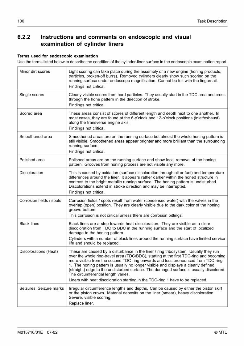
100 Task Description
6.2.2 Instructions and comments on endoscopic and visualexamination of cylinder liners
Terms used for endoscopic examinationUse the terms listed below to describe the condition of the cylinder-liner surface in the endoscopic examination report.
Minor dirt scores Light scoring can take place during the assembly of a new engine (honing products,particles, broken-off burrs). Removed cylinders clearly show such scoring on therunning surface under endoscope magnification. Cannot be felt with the fingernail.Findings not critical.
Single scores Clearly visible scores from hard particles. They usually start in the TDC area and crossthrough the hone pattern in the direction of stroke.Findings not critical.
Scored area These areas consist of scores of different length and depth next to one another. Inmost cases, they are found at the 6-o’clock and 12-o’clock positions (inlet/exhaust)along the transverse engine axis.Findings not critical.
Smoothened area Smoothened areas are on the running surface but almost the whole honing pattern isstill visible. Smoothened areas appear brighter and more brilliant than the surroundingrunning surface.Findings not critical.
Polished area Polished areas are on the running surface and show local removal of the honingpattern. Grooves from honing process are not visible any more.
Discoloration This is caused by oxidation (surface discoloration through oil or fuel) and temperaturedifferences around the liner. It appears rather darker within the honed structure incontrast to the bright metallic running surface. The honing pattern is undisturbed.Discolorations extend in stroke direction and may be interrupted.Findings not critical.
Corrosion fields / spots Corrosion fields / spots result from water (condensed water) with the valves in theoverlap (open) position. They are clearly visible due to the dark color of the honinggroove bottom.This corrosion is not critical unless there are corrosion pittings.
Black lines Black lines are a step towards heat discoloration. They are visible as a cleardiscoloration from TDC to BDC in the running surface and the start of localizeddamage to the honing pattern.Cylinders with a number of black lines around the running surface have limited servicelife and should be replaced.
Discolorations (Heat) These are caused by a disturbance in the liner / ring tribosystem. Usually they runover the whole ring-travel area (TDC/BDC), starting at the first TDC-ring and becomingmore visible from the second TDC-ring onwards and less pronounced from TDC-ring1. The honing pattern is usually no longer visible and displays a clearly defined(straight) edge to the undisturbed surface. The damaged surface is usually discolored.The circumferential length varies.Liners with heat discoloration starting in the TDC-ring 1 have to be replaced.
Seizures, Seizure marks Irregular circumference lengths and depths. Can be caused by either the piston skirtor the piston crown. Material deposits on the liner (smear), heavy discoloration.Severe, visible scoring.Replace liner.
M015710/01E 07-02 © MTU
Task Description 101
Evaluation of findings and further measuresThe findings in the start phase of oxidation discoloration and heat discoloration are similar. Thorough investigationand compliance with the above evaluation criteria allows a definite evaluation. To avoid unnecessary disassemblywork, it is recommended that another inspection be carried out after further operation of the engine.
M015710/01E 07-02 © MTU
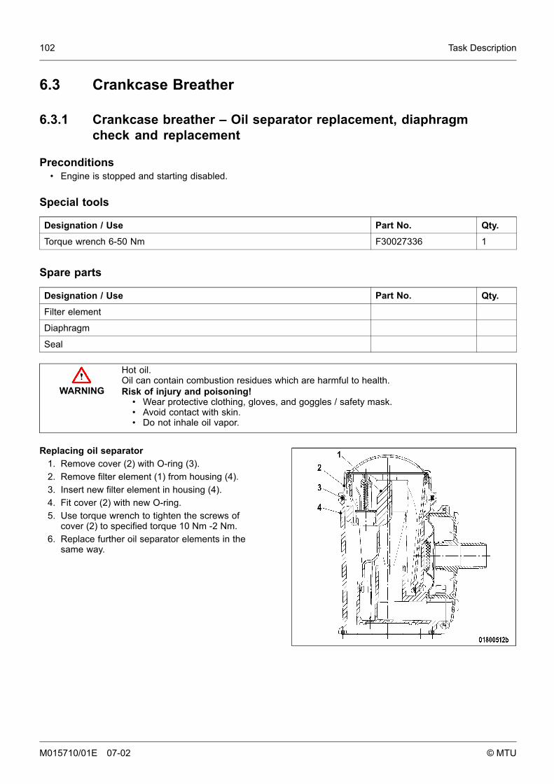
102 Task Description
6.3 Crankcase Breather
6.3.1 Crankcase breather – Oil separator replacement, diaphragmcheck and replacement
Preconditions• Engine is stopped and starting disabled.
Special tools
Designation / Use Part No. Qty.
Torque wrench 6-50 Nm F30027336 1
Spare parts
Designation / Use Part No. Qty.
Filter element
Diaphragm
Seal
WARNING
Hot oil.Oil can contain combustion residues which are harmful to health.Risk of injury and poisoning!
• Wear protective clothing, gloves, and goggles / safety mask.• Avoid contact with skin.• Do not inhale oil vapor.
Replacing oil separator1. Remove cover (2) with O-ring (3).2. Remove filter element (1) from housing (4).3. Insert new filter element in housing (4).4. Fit cover (2) with new O-ring.5. Use torque wrench to tighten the screws of
cover (2) to specified torque 10 Nm -2 Nm.6. Replace further oil separator elements in the
same way.
M015710/01E 07-02 © MTU
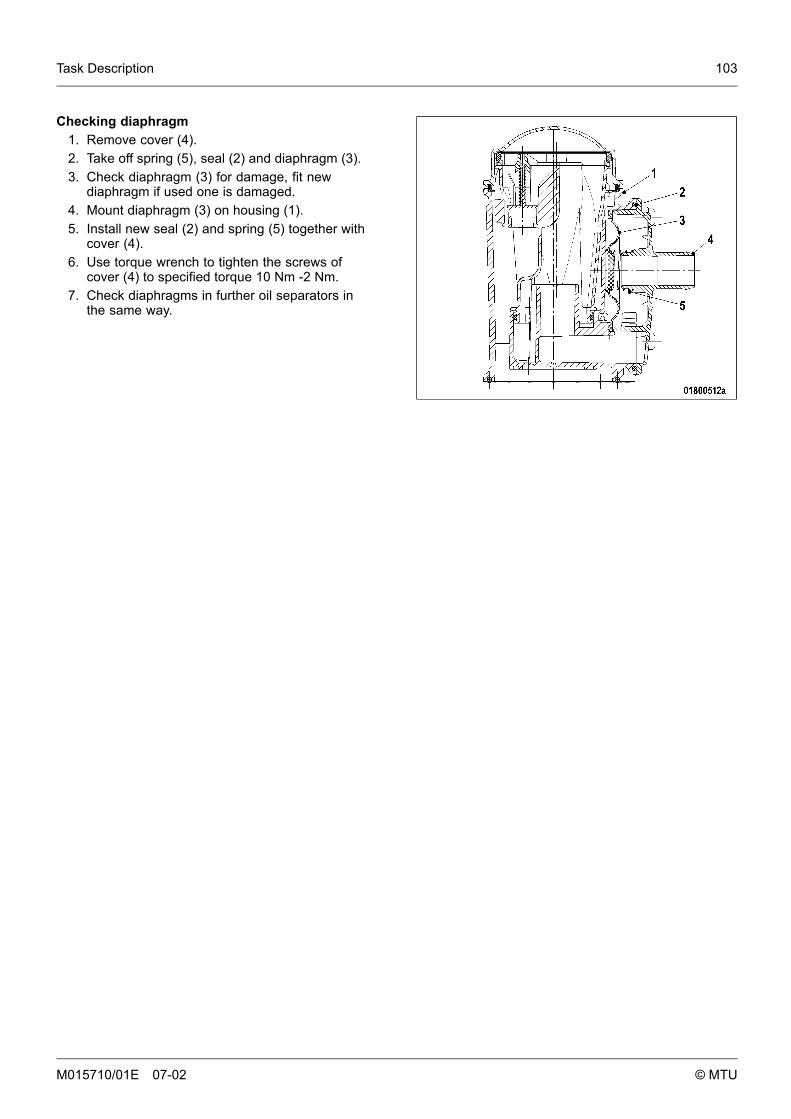
Task Description 103
Checking diaphragm1. Remove cover (4).2. Take off spring (5), seal (2) and diaphragm (3).3. Check diaphragm (3) for damage, fit new
diaphragm if used one is damaged.4. Mount diaphragm (3) on housing (1).5. Install new seal (2) and spring (5) together with
cover (4).6. Use torque wrench to tighten the screws of
cover (4) to specified torque 10 Nm -2 Nm.7. Check diaphragms in further oil separators in
the same way.
M015710/01E 07-02 © MTU
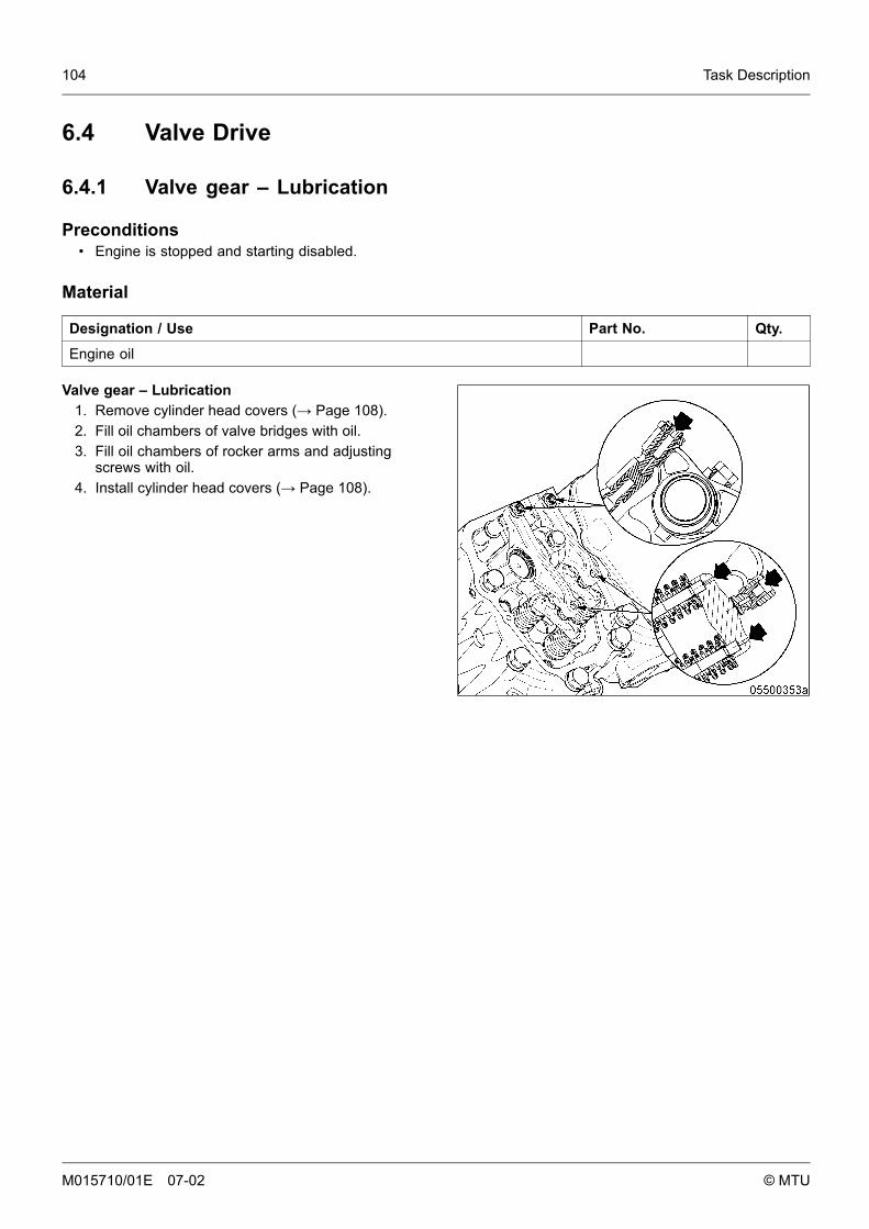
104 Task Description
6.4 Valve Drive
6.4.1 Valve gear – Lubrication
Preconditions• Engine is stopped and starting disabled.
Material
Designation / Use Part No. Qty.
Engine oil
Valve gear – Lubrication1. Remove cylinder head covers (→ Page 108).2. Fill oil chambers of valve bridges with oil.3. Fill oil chambers of rocker arms and adjusting
screws with oil.4. Install cylinder head covers (→ Page 108).
M015710/01E 07-02 © MTU
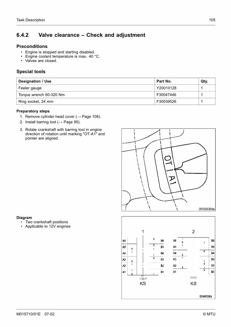
Task Description 105
6.4.2 Valve clearance – Check and adjustment
Preconditions• Engine is stopped and starting disabled.• Engine coolant temperature is max. 40 °C.• Valves are closed.
Special tools
Designation / Use Part No. Qty.
Feeler gauge Y20010128 1
Torque wrench 60-320 Nm F30047446 1
Ring socket, 24 mm F30039526 1
Preparatory steps1. Remove cylinder head cover (→ Page 108).2. Install barring tool (→ Page 95).
3. Rotate crankshaft with barring tool in enginedirection of rotation until marking "OT-A1" andpointer are aligned.
Diagram• Two crankshaft positions• Applicable to 12V engines
M015710/01E 07-02 © MTU
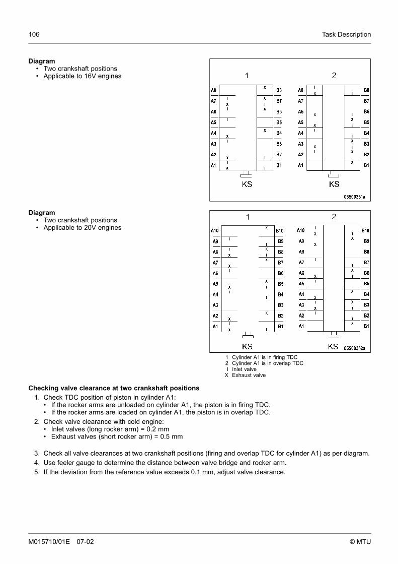
106 Task Description
Diagram• Two crankshaft positions• Applicable to 16V engines
1 Cylinder A1 is in firing TDC2 Cylinder A1 is in overlap TDCI Inlet valve
X Exhaust valve
Diagram• Two crankshaft positions• Applicable to 20V engines
Checking valve clearance at two crankshaft positions1. Check TDC position of piston in cylinder A1:
• If the rocker arms are unloaded on cylinder A1, the piston is in firing TDC.• If the rocker arms are loaded on cylinder A1, the piston is in overlap TDC.
2. Check valve clearance with cold engine:• Inlet valves (long rocker arm) = 0.2 mm• Exhaust valves (short rocker arm) = 0.5 mm
3. Check all valve clearances at two crankshaft positions (firing and overlap TDC for cylinder A1) as per diagram.4. Use feeler gauge to determine the distance between valve bridge and rocker arm.5. If the deviation from the reference value exceeds 0.1 mm, adjust valve clearance.
M015710/01E 07-02 © MTU
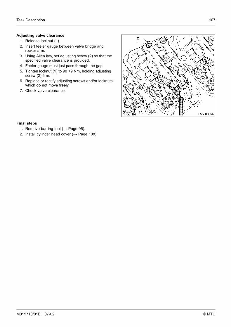
Task Description 107
Adjusting valve clearance1. Release locknut (1).2. Insert feeler gauge between valve bridge and
rocker arm.3. Using Allen key, set adjusting screw (2) so that the
specified valve clearance is provided.4. Feeler gauge must just pass through the gap.5. Tighten locknut (1) to 90 +9 Nm, holding adjusting
screw (2) firm.6. Replace or rectify adjusting screws and/or locknuts
which do not move freely.7. Check valve clearance.
Final steps1. Remove barring tool (→ Page 95).2. Install cylinder head cover (→ Page 108).
M015710/01E 07-02 © MTU
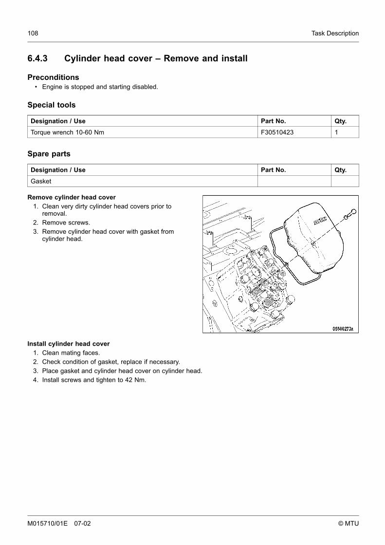
108 Task Description
6.4.3 Cylinder head cover – Remove and install
Preconditions• Engine is stopped and starting disabled.
Special tools
Designation / Use Part No. Qty.
Torque wrench 10-60 Nm F30510423 1
Spare parts
Designation / Use Part No. Qty.
Gasket
Remove cylinder head cover1. Clean very dirty cylinder head covers prior to
removal.2. Remove screws.3. Remove cylinder head cover with gasket from
cylinder head.
Install cylinder head cover1. Clean mating faces.2. Check condition of gasket, replace if necessary.3. Place gasket and cylinder head cover on cylinder head.4. Install screws and tighten to 42 Nm.
M015710/01E 07-02 © MTU
Task Description 109
6.5 Injector
6.5.1 Injector – Replacement
Spare parts
Designation / Use Part No. Qty.
Injector
Remove injector and install new one (→ Page 110).
M015710/01E 07-02 © MTU
110 Task Description
6.5.2 Injector – Removal and Installation
Preconditions• Engine is stopped and starting disabled.
Special tools
Designation / Use Part No. Qty.
Puller F6784183 1
Press-in tool F6784167 1
Torque wrench 10-60 Nm F30510423 1
Socket wrench, 17 mm F30025896 1
Socket wrench, 19 mm F30025897 1
Torque wrench 60-320 Nm F30047446 1
Ratchet adapter F30027341 1
Material
Designation / Use Part No. Qty.
Petroleum jelly
WARNING
Fuels are combustible.Risk of fire and explosion!
• Avoid naked flames, electrical sparks and ignition sources.• Do not smoke.
Preparatory steps1. Shut off fuel supply to engine.2. Remove cylinder head cover (→ Page 108).
M015710/01E 07-02 © MTU

Task Description 111
Injector removal1. Withdraw cable connector on injector.
2. Remove screw (2) and take off hold-downclamp (1).
3. Remove HP fuel line (4).
Note: The injector accumulator will be emptiedwhen removing the adapter.
4. Unscrew adapter (3) until only the last two to threecourses of the thread are engaged.
5. Allow the fuel to drain off and collect it in asuitable container.
6. Unscrew adapter completely.
7. Fit puller and withdraw injector.
M015710/01E 07-02 © MTU
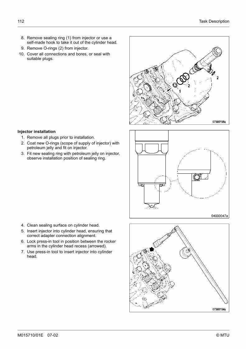
112 Task Description
8. Remove sealing ring (1) from injector or use aself-made hook to take it out of the cylinder head.
9. Remove O-rings (2) from injector.10. Cover all connections and bores, or seal with
suitable plugs.
Injector installation1. Remove all plugs prior to installation.2. Coat new O-rings (scope of supply of injector) with
petroleum jelly and fit on injector.3. Fit new sealing ring with petroleum jelly on injector,
observe installation position of sealing ring.
4. Clean sealing surface on cylinder head.5. Insert injector into cylinder head, ensuring that
correct adapter connection alignment.6. Lock press-in tool in position between the rocker
arms in the cylinder head recess (arrowed).7. Use press-in tool to insert injector into cylinder
head.
M015710/01E 07-02 © MTU
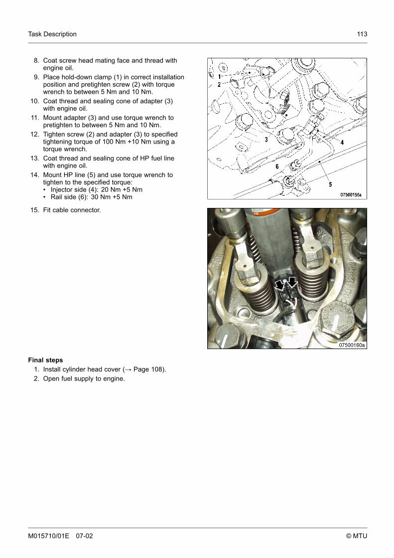
Task Description 113
8. Coat screw head mating face and thread withengine oil.
9. Place hold-down clamp (1) in correct installationposition and pretighten screw (2) with torquewrench to between 5 Nm and 10 Nm.
10. Coat thread and sealing cone of adapter (3)with engine oil.
11. Mount adapter (3) and use torque wrench topretighten to between 5 Nm and 10 Nm.
12. Tighten screw (2) and adapter (3) to specifiedtightening torque of 100 Nm +10 Nm using atorque wrench.
13. Coat thread and sealing cone of HP fuel linewith engine oil.
14. Mount HP line (5) and use torque wrench totighten to the specified torque:• Injector side (4): 20 Nm +5 Nm• Rail side (6): 30 Nm +5 Nm
15. Fit cable connector.
Final steps1. Install cylinder head cover (→ Page 108).2. Open fuel supply to engine.
M015710/01E 07-02 © MTU
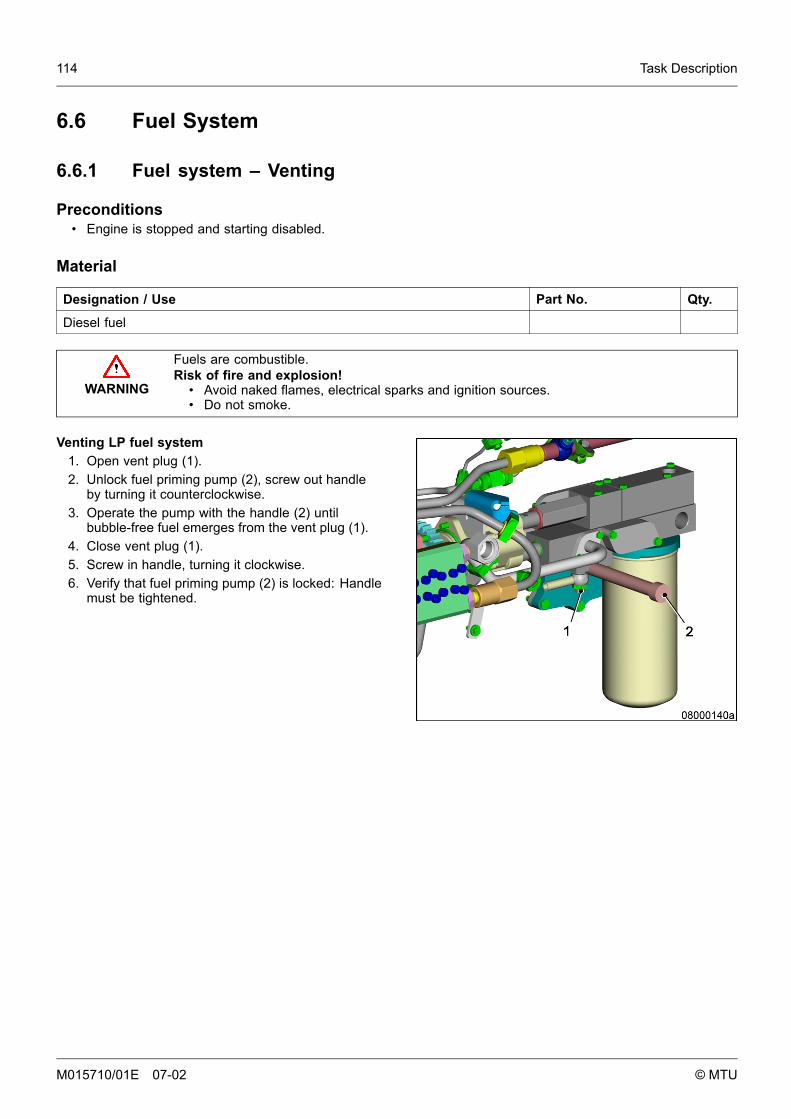
114 Task Description
6.6 Fuel System
6.6.1 Fuel system – Venting
Preconditions• Engine is stopped and starting disabled.
Material
Designation / Use Part No. Qty.
Diesel fuel
WARNING
Fuels are combustible.Risk of fire and explosion!
• Avoid naked flames, electrical sparks and ignition sources.• Do not smoke.
Venting LP fuel system1. Open vent plug (1).2. Unlock fuel priming pump (2), screw out handle
by turning it counterclockwise.3. Operate the pump with the handle (2) until
bubble-free fuel emerges from the vent plug (1).4. Close vent plug (1).5. Screw in handle, turning it clockwise.6. Verify that fuel priming pump (2) is locked: Handle
must be tightened.
M015710/01E 07-02 © MTU
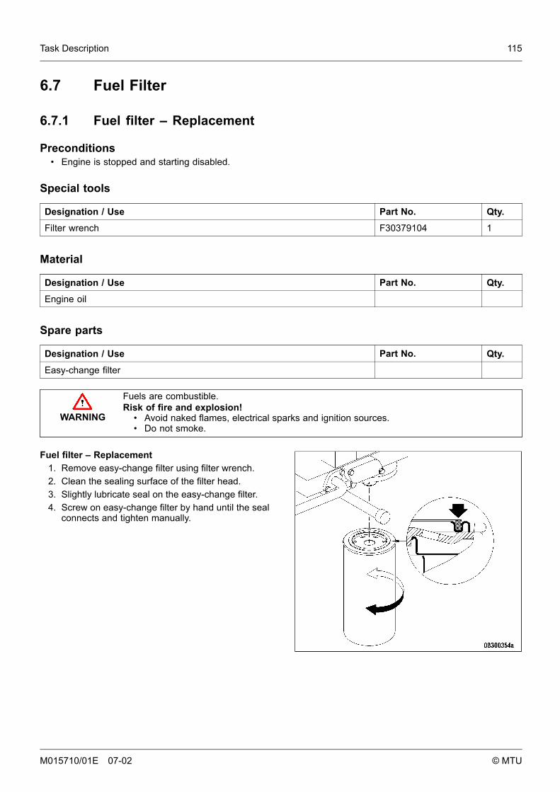
Task Description 115
6.7 Fuel Filter
6.7.1 Fuel filter – Replacement
Preconditions• Engine is stopped and starting disabled.
Special tools
Designation / Use Part No. Qty.
Filter wrench F30379104 1
Material
Designation / Use Part No. Qty.
Engine oil
Spare parts
Designation / Use Part No. Qty.
Easy-change filter
WARNING
Fuels are combustible.Risk of fire and explosion!
• Avoid naked flames, electrical sparks and ignition sources.• Do not smoke.
Fuel filter – Replacement1. Remove easy-change filter using filter wrench.2. Clean the sealing surface of the filter head.3. Slightly lubricate seal on the easy-change filter.4. Screw on easy-change filter by hand until the seal
connects and tighten manually.
M015710/01E 07-02 © MTU

116 Task Description
6.7.2 Fuel prefilter cleaning
Preconditions• Engine is stopped and starting disabled.
Material
Designation / Use Part No. Qty.
Diesel fuel
Spare parts
Designation / Use Part No. Qty.
Sealing ring
WARNING
Fuels are combustible.Risk of fire and explosion!
• Avoid naked flames, electrical sparks and ignition sources.• Do not smoke.
Fuel prefilter cleaning1. Shut off fuel supply.2. Remove nuts from filter head.3. Take off filter housing and drain fuel into
appropriate container.4. Remove filter-element securing nut and remove
filter element by pulling it downwards.5. Wash filter element in clean fuel using a smooth
brush.6. Wash filter housing with clean fuel.7. Insert filter element into filter housing and secure
with nut.8. Place new sealing ring into groove in filter head.9. Fit cover with seal and secure it with nuts
crosswise.10. Open fuel supply.
M015710/01E 07-02 © MTU

Task Description 117
6.7.3 Fuel prefilter – differential pressure check and adjustment of gauge
DANGER
Unguarded rotating and moving engine components.Risk of serious injury – danger to life!
• Take special care when working on a running engine.
WARNING
Engine noise above 85 dB (A).Risk of damage to hearing!
• Wear ear protectors.
Setting adjustable pointer of differential pressuregauge
1. After installation of a new filter element, alignadjustable pointer (2) with pressure-indicatingpointer (3) of pressure gauge (1).
2. Verify that differential pressure is within the limit.
Fuel prefilter – checking differential pressure1. With the engine running at full load or rated power, read off pressure at gauge (1).2. If differential pressure as indicated between position of adjustable pointer (2) and pressure-indicating pointer
(3) of pressure gauge is ≥ 0.3 bar, flush filter element of the cut-in filter (→ Page 120).
M015710/01E 07-02 © MTU
118 Task Description
6.7.4 Fuel prefilter – draining
Preconditions• Engine is stopped and starting disabled.
Material
Designation / Use Part No. Qty.
Diesel fuel
Spare parts
Designation / Use Part No. Qty.
Gasket
WARNING
Fuels are combustible.Risk of fire and explosion!
• Avoid naked flames, electrical sparks and ignition sources.• Do not smoke.
M015710/01E 07-02 © MTU

Task Description 119
I Left filter cut inII Right filter cut in
Fuel prefilter – draining1. Cut out the filter to be drained.
2. Open vent plug (5) of the filter to be drained.3. Unlock drain cock (6) by pressing toggle and
open it.4. Drain water and contaminants from the filter until
pure fuel emerges.5. Close drain cock (6).6. Remove screws securing the cover and take
off cover (2).7. Fill filter housing with clean fuel.8. Place new gasket in cover (2).9. Fit cover with gasket and secure it with screws.
10. Cut the cut-out filter in again.11. When fuel emerges from system, close vent
plug (5).
M015710/01E 07-02 © MTU
120 Task Description
6.7.5 Fuel prefilter – flushing
Material
Designation / Use Part No. Qty.
Diesel fuel
Spare parts
Designation / Use Part No. Qty.
Gasket
DANGER
Unguarded rotating and moving engine components.Risk of serious injury – danger to life!
• Take special care when working on a running engine.
WARNING
Fuels are combustible.Risk of fire and explosion!
• Avoid naked flames, electrical sparks and ignition sources.• Do not smoke.
WARNING
Engine noise above 85 dB (A).Risk of damage to hearing!
• Wear ear protectors.
M015710/01E 07-02 © MTU
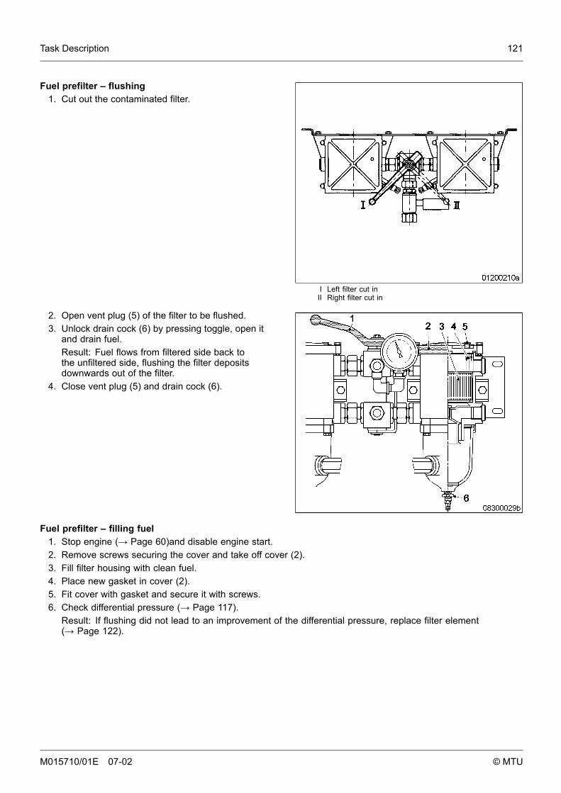
Task Description 121
I Left filter cut inII Right filter cut in
Fuel prefilter – flushing1. Cut out the contaminated filter.
2. Open vent plug (5) of the filter to be flushed.3. Unlock drain cock (6) by pressing toggle, open it
and drain fuel.Result: Fuel flows from filtered side back tothe unfiltered side, flushing the filter depositsdownwards out of the filter.
4. Close vent plug (5) and drain cock (6).
Fuel prefilter – filling fuel1. Stop engine (→ Page 60)and disable engine start.2. Remove screws securing the cover and take off cover (2).3. Fill filter housing with clean fuel.4. Place new gasket in cover (2).5. Fit cover with gasket and secure it with screws.6. Check differential pressure (→ Page 117).
Result: If flushing did not lead to an improvement of the differential pressure, replace filter element(→ Page 122).
M015710/01E 07-02 © MTU
122 Task Description
6.7.6 Fuel prefilter – filter element replacement
Preconditions• Engine is stopped and starting disabled.
Material
Designation / Use Part No. Qty.
Diesel fuel
Spare parts
Designation / Use Part No. Qty.
Filter element
Gasket
WARNING
Fuels are combustible.Risk of fire and explosion!
• Avoid naked flames, electrical sparks and ignition sources.• Do not smoke.
M015710/01E 07-02 © MTU

Task Description 123
I Left filter cut inII Right filter cut in
Fuel prefilter – filter element replacement1. Cut out the contaminated filter.
2. Open vent plug (5) of the contaminated filter.3. Unlock drain cock (6) by pressing toggle and
open it.4. Drain water and contaminants from the filter.5. Close drain cock (6).6. Remove screws securing the cover and take
off cover (2).7. Remove spring (4) and filter element (3).8. Insert new filter element (3) and spring (4).9. Fill filter housing with clean fuel.
10. Place new gasket in cover (2).11. Fit cover with gasket and secure it with screws.12. Cut the cut-out filter in again.13. Close vent plug (5) when fuel emerges.14. Align adjustable pointer of differential pressure
gauge with pressure-indicating pointer.(→ Page 117).
M015710/01E 07-02 © MTU
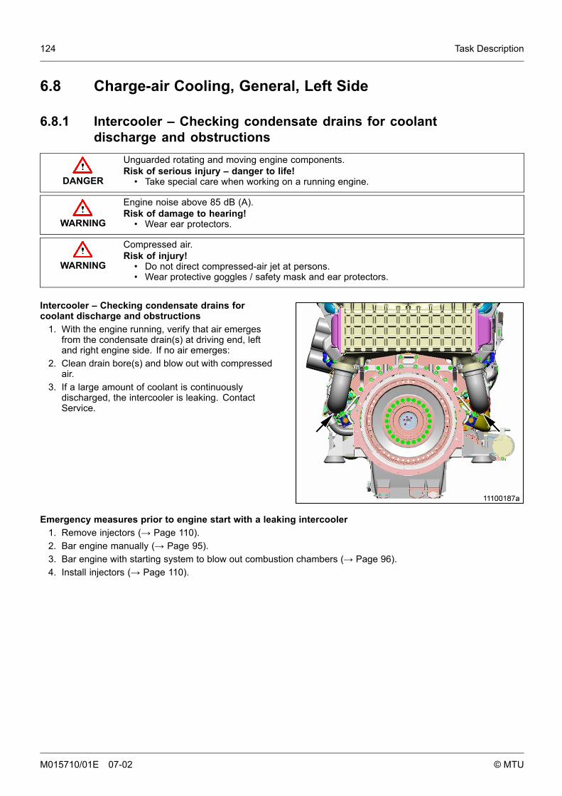
124 Task Description
6.8 Charge-air Cooling, General, Left Side
6.8.1 Intercooler – Checking condensate drains for coolantdischarge and obstructions
DANGER
Unguarded rotating and moving engine components.Risk of serious injury – danger to life!
• Take special care when working on a running engine.
WARNING
Engine noise above 85 dB (A).Risk of damage to hearing!
• Wear ear protectors.
WARNING
Compressed air.Risk of injury!
• Do not direct compressed-air jet at persons.• Wear protective goggles / safety mask and ear protectors.
Intercooler – Checking condensate drains forcoolant discharge and obstructions
1. With the engine running, verify that air emergesfrom the condensate drain(s) at driving end, leftand right engine side. If no air emerges:
2. Clean drain bore(s) and blow out with compressedair.
3. If a large amount of coolant is continuouslydischarged, the intercooler is leaking. ContactService.
Emergency measures prior to engine start with a leaking intercooler1. Remove injectors (→ Page 110).2. Bar engine manually (→ Page 95).3. Bar engine with starting system to blow out combustion chambers (→ Page 96).4. Install injectors (→ Page 110).
M015710/01E 07-02 © MTU
Task Description 125
6.9 Air Filter
6.9.1 Air filter replacement
Spare parts
Designation / Use Part No. Qty.
Air filter
Remove air filter and install new one (→ Page 127).
Reset signal ring of service indicator (→ Page 129).
M015710/01E 07-02 © MTU
126 Task Description
6.9.2 Air filter – Check
Spare parts
Designation / Use Part No. Qty.
Air filter
Air filter – Check1. Check entire circumference of air filter for damage.2. Fit new air filter if damaged (→ Page 127).
M015710/01E 07-02 © MTU
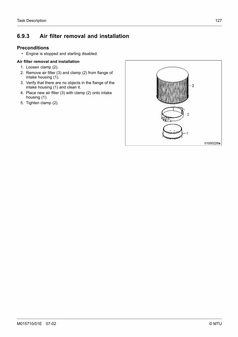
Task Description 127
6.9.3 Air filter removal and installation
Preconditions• Engine is stopped and starting disabled.
Air filter removal and installation1. Loosen clamp (2).2. Remove air filter (3) and clamp (2) from flange of
intake housing (1).3. Verify that there are no objects in the flange of the
intake housing (1) and clean it.4. Place new air filter (3) with clamp (2) onto intake
housing (1).5. Tighten clamp (2).
M015710/01E 07-02 © MTU
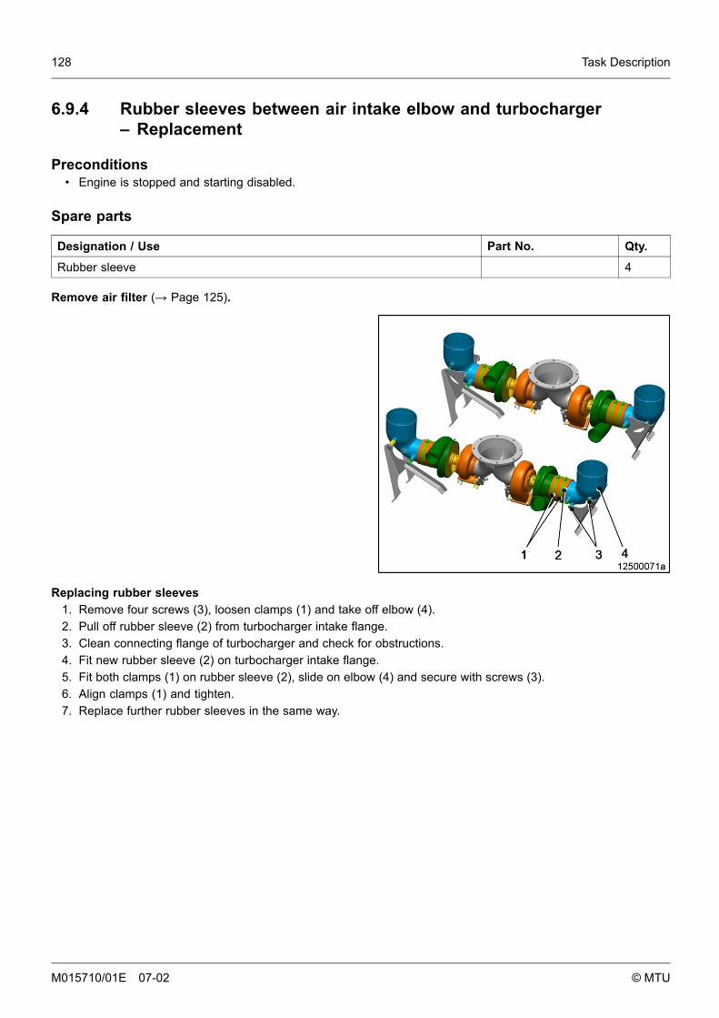
128 Task Description
6.9.4 Rubber sleeves between air intake elbow and turbocharger– Replacement
Preconditions• Engine is stopped and starting disabled.
Spare parts
Designation / Use Part No. Qty.
Rubber sleeve 4
Remove air filter (→ Page 125).
Replacing rubber sleeves1. Remove four screws (3), loosen clamps (1) and take off elbow (4).2. Pull off rubber sleeve (2) from turbocharger intake flange.3. Clean connecting flange of turbocharger and check for obstructions.4. Fit new rubber sleeve (2) on turbocharger intake flange.5. Fit both clamps (1) on rubber sleeve (2), slide on elbow (4) and secure with screws (3).6. Align clamps (1) and tighten.7. Replace further rubber sleeves in the same way.
M015710/01E 07-02 © MTU
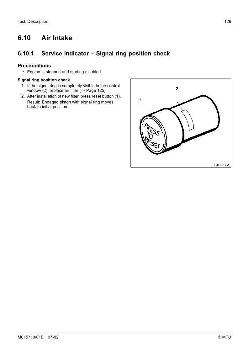
Task Description 129
6.10 Air Intake
6.10.1 Service indicator – Signal ring position check
Preconditions• Engine is stopped and starting disabled.
Signal ring position check1. If the signal ring is completely visible in the control
window (2), replace air filter (→ Page 125).2. After installation of new filter, press reset button (1).
Result: Engaged piston with signal ring movesback to initial position.
M015710/01E 07-02 © MTU
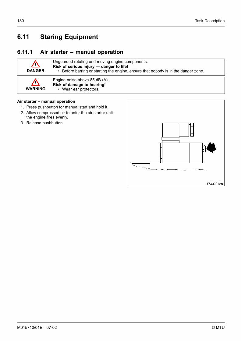
130 Task Description
6.11 Staring Equipment
6.11.1 Air starter – manual operation
DANGER
Unguarded rotating and moving engine components.Risk of serious injury — danger to life!
• Before barring or starting the engine, ensure that nobody is in the danger zone.
WARNING
Engine noise above 85 dB (A).Risk of damage to hearing!
• Wear ear protectors.
Air starter – manual operation1. Press pushbutton for manual start and hold it.2. Allow compressed air to enter the air starter until
the engine fires evenly.3. Release pushbutton.
M015710/01E 07-02 © MTU
Task Description 131
6.11.2 Starter – Condition check
Preconditions• Engine is stopped and starting disabled.
Starter – Condition check1. Check starter securing screws for secure seating.2. Tighten loose screw connections.3. Check wiring (→ Page 155).
M015710/01E 07-02 © MTU
132 Task Description
6.12 Lube-oil System, Lube-oil Circuit
6.12.1 Engine oil – Change
Preconditions• Engine is stopped and starting disabled.• Engine is at operating temperature.• MTU Fluids and Lubricants Specification (A001061/..) is available.
Special tools
Designation / Use Part No. Qty.
Torque wrench F30027337 1
Ratchet adapter F30027341 1
Material
Designation / Use Part No. Qty.
Engine oil
Spare parts
Designation / Use Part No. Qty.
Sealing ring
WARNING
Hot oil.Oil can contain combustion residues which are harmful to health.Risk of injury and poisoning!
• Wear protective clothing, gloves, and goggles / safety mask.• Avoid contact with skin.• Do not inhale oil vapor.
Oil change without semirotary hand pump: Draining oil at drain plug(s) on oil pan1. Provide a suitable container in which to collect the oil.2. Remove drain plug(s) and drain oil.3. Install drain plug(s) with new sealing ring.
Oil change using semirotary hand pump: Oil extraction1. Provide a suitable container in which to collect the oil.2. Extract all oil from oil pan using the hand pump.
M015710/01E 07-02 © MTU
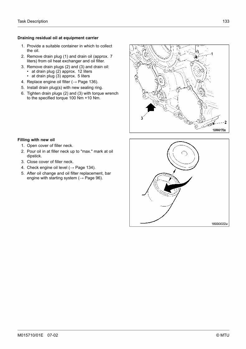
Task Description 133
Draining residual oil at equipment carrier
1. Provide a suitable container in which to collectthe oil.
2. Remove drain plug (1) and drain oil (approx. 7liters) from oil heat exchanger and oil filter.
3. Remove drain plugs (2) and (3) and drain oil:• at drain plug (2) approx. 12 liters• at drain plug (3) approx. 5 liters
4. Replace engine oil filter (→ Page 136).5. Install drain plug(s) with new sealing ring.6. Tighten drain plugs (2) and (3) with torque wrench
to the specified torque 100 Nm +10 Nm.
Filling with new oil1. Open cover of filler neck.2. Pour oil in at filler neck up to "max." mark at oil
dipstick.3. Close cover of filler neck.4. Check engine oil level (→ Page 134).5. After oil change and oil filter replacement, bar
engine with starting system (→ Page 96).
M015710/01E 07-02 © MTU
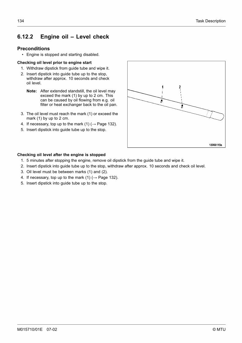
134 Task Description
6.12.2 Engine oil – Level check
Preconditions• Engine is stopped and starting disabled.
Checking oil level prior to engine start1. Withdraw dipstick from guide tube and wipe it.2. Insert dipstick into guide tube up to the stop,
withdraw after approx. 10 seconds and checkoil level.
Note: After extended standstill, the oil level mayexceed the mark (1) by up to 2 cm. Thiscan be caused by oil flowing from e.g. oilfilter or heat exchanger back to the oil pan.
3. The oil level must reach the mark (1) or exceed themark (1) by up to 2 cm.
4. If necessary, top up to the mark (1) (→ Page 132).5. Insert dipstick into guide tube up to the stop.
Checking oil level after the engine is stopped1. 5 minutes after stopping the engine, remove oil dipstick from the guide tube and wipe it.2. Insert dipstick into guide tube up to the stop, withdraw after approx. 10 seconds and check oil level.3. Oil level must be between marks (1) and (2).4. If necessary, top up to the mark (1) (→ Page 132).5. Insert dipstick into guide tube up to the stop.
M015710/01E 07-02 © MTU
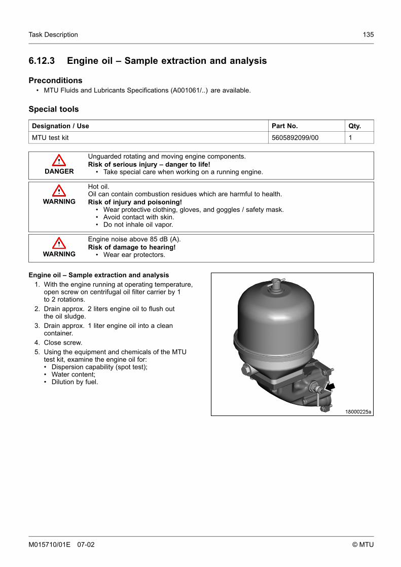
Task Description 135
6.12.3 Engine oil – Sample extraction and analysis
Preconditions• MTU Fluids and Lubricants Specifications (A001061/..) are available.
Special tools
Designation / Use Part No. Qty.
MTU test kit 5605892099/00 1
DANGER
Unguarded rotating and moving engine components.Risk of serious injury – danger to life!
• Take special care when working on a running engine.
WARNING
Hot oil.Oil can contain combustion residues which are harmful to health.Risk of injury and poisoning!
• Wear protective clothing, gloves, and goggles / safety mask.• Avoid contact with skin.• Do not inhale oil vapor.
WARNING
Engine noise above 85 dB (A).Risk of damage to hearing!
• Wear ear protectors.
Engine oil – Sample extraction and analysis1. With the engine running at operating temperature,
open screw on centrifugal oil filter carrier by 1to 2 rotations.
2. Drain approx. 2 liters engine oil to flush outthe oil sludge.
3. Drain approx. 1 liter engine oil into a cleancontainer.
4. Close screw.5. Using the equipment and chemicals of the MTU
test kit, examine the engine oil for:• Dispersion capability (spot test);• Water content;• Dilution by fuel.
M015710/01E 07-02 © MTU
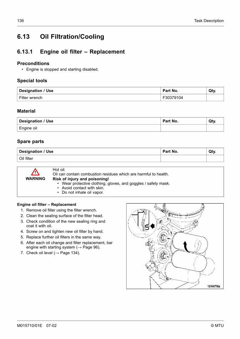
136 Task Description
6.13 Oil Filtration/Cooling
6.13.1 Engine oil filter – Replacement
Preconditions• Engine is stopped and starting disabled.
Special tools
Designation / Use Part No. Qty.
Filter wrench F30379104
Material
Designation / Use Part No. Qty.
Engine oil
Spare parts
Designation / Use Part No. Qty.
Oil filter
WARNING
Hot oil.Oil can contain combustion residues which are harmful to health.Risk of injury and poisoning!
• Wear protective clothing, gloves, and goggles / safety mask.• Avoid contact with skin.• Do not inhale oil vapor.
Engine oil filter – Replacement1. Remove oil filter using the filter wrench.2. Clean the sealing surface of the filter head.3. Check condition of the new sealing ring and
coat it with oil.4. Screw on and tighten new oil filter by hand.5. Replace further oil filters in the same way.6. After each oil change and filter replacement, bar
engine with starting system (→ Page 96).7. Check oil level (→ Page 134).
M015710/01E 07-02 © MTU
Task Description 137
6.13.2 Centrifugal oil filter – Cleaning and filter-sleeve replacement
Preconditions• Engine is stopped and starting disabled.
Special tools
Designation / Use Part No. Qty.
Torque wrench 6-50 Nm F30027336 1
Material
Designation / Use Part No. Qty.
Cleaner Hakutex 60
Spare parts
Designation / Use Part No. Qty.
Filter sleeve
Sealing ring
Sealing ring
WARNING
Hot oil.Oil can contain combustion residues which are harmful to health.Risk of injury and poisoning!
• Wear protective clothing, gloves, and goggles / safety mask.• Avoid contact with skin.• Do not inhale oil vapor.
WARNING
Compressed air.Risk of injury!
• Do not direct compressed-air jet at persons.• Wear protective goggles / safety mask and ear protectors.
M015710/01E 07-02 © MTU
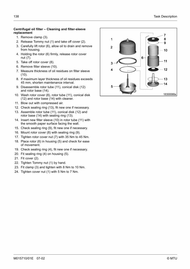
138 Task Description
Centrifugal oil filter – Cleaning and filter-sleevereplacement
1. Remove clamp (3).2. Release Tommy nut (1) and take off cover (2).3. Carefully lift rotor (6), allow oil to drain and remove
from housing.4. Holding the rotor (6) firmly, release rotor cover
nut (7).5. Take off rotor cover (8).6. Remove filter sleeve (10).7. Measure thickness of oil residues on filter sleeve
(10).8. If maximum layer thickness of oil residues exceeds
45 mm, shorten maintenance interval.9. Disassemble rotor tube (11), conical disk (12)
and rotor base (14).10. Wash rotor cover (8), rotor tube (11), conical disk
(12) and rotor base (14) with cleaner.11. Blow out with compressed air.12. Check sealing ring (13), fit new one if necessary.13. Assemble rotor tube (11), conical disk (12) and
rotor base (14) with sealing ring (13).14. Insert new filter sleeve (10) in rotor tube (11) with
the smooth paper surface facing the wall.15. Check sealing ring (9), fit new one if necessary.16. Mount rotor cover (8) with sealing ring (9).17. Tighten rotor cover nut (7) with 35 Nm to 45 Nm.18. Place rotor (6) in housing (5) and check for ease
of movement.19. Check sealing ring (4), fit new one if necessary.20. Fit sealing ring (4) on housing (5).21. Fit cover (2).22. Tighten Tommy nut (1) by hand.23. Fit clamp (3) and tighten with 8 Nm to 10 Nm.24. Tighten cover nut (1) with 5 Nm to 7 Nm.
M015710/01E 07-02 © MTU
Task Description 139
6.14 Cooling Circuit, General, HT Circuit
6.14.1 Engine coolant – Change
Material
Designation / Use Part No. Qty.
Engine coolant
Drain engine coolant (→ Page 142).
Fill engine coolant system (→ Page 140).
M015710/01E 07-02 © MTU
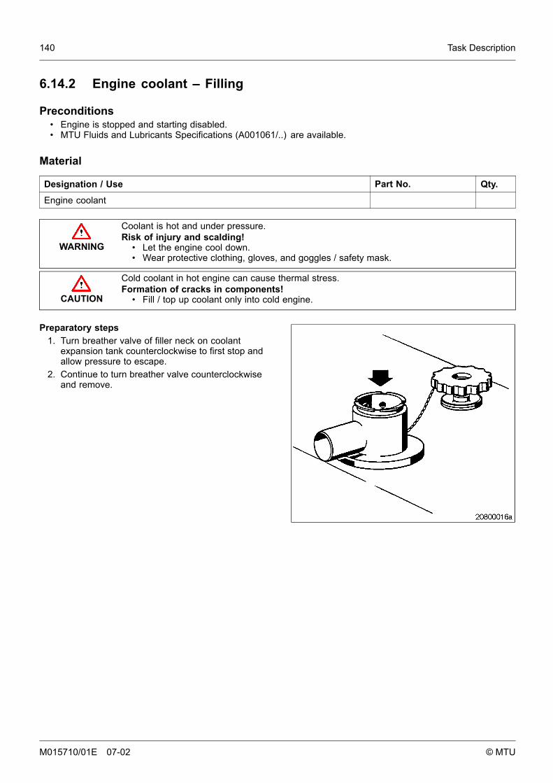
140 Task Description
6.14.2 Engine coolant – Filling
Preconditions• Engine is stopped and starting disabled.• MTU Fluids and Lubricants Specifications (A001061/..) are available.
Material
Designation / Use Part No. Qty.
Engine coolant
WARNING
Coolant is hot and under pressure.Risk of injury and scalding!
• Let the engine cool down.• Wear protective clothing, gloves, and goggles / safety mask.
CAUTION
Cold coolant in hot engine can cause thermal stress.Formation of cracks in components!
• Fill / top up coolant only into cold engine.
Preparatory steps1. Turn breather valve of filler neck on coolant
expansion tank counterclockwise to first stop andallow pressure to escape.
2. Continue to turn breather valve counterclockwiseand remove.
M015710/01E 07-02 © MTU
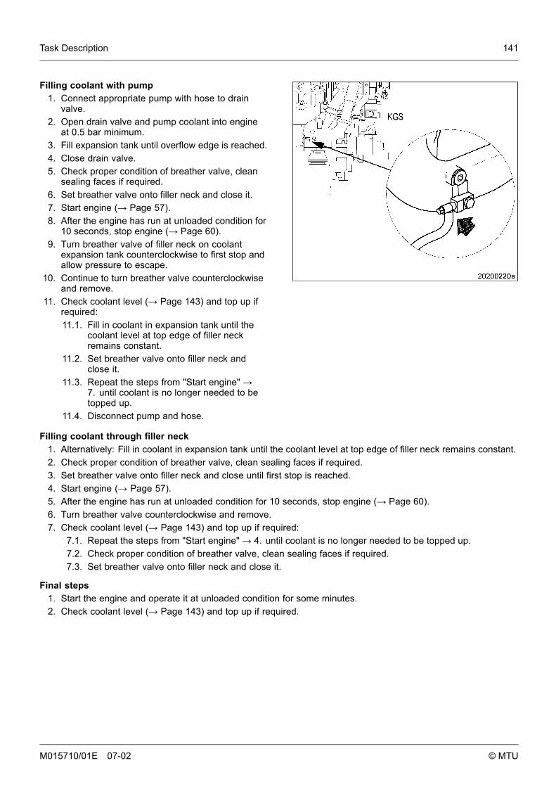
Task Description 141
Filling coolant with pump1. Connect appropriate pump with hose to drain
valve.2. Open drain valve and pump coolant into engine
at 0.5 bar minimum.3. Fill expansion tank until overflow edge is reached.4. Close drain valve.5. Check proper condition of breather valve, clean
sealing faces if required.6. Set breather valve onto filler neck and close it.7. Start engine (→ Page 57).8. After the engine has run at unloaded condition for
10 seconds, stop engine (→ Page 60).9. Turn breather valve of filler neck on coolant
expansion tank counterclockwise to first stop andallow pressure to escape.
10. Continue to turn breather valve counterclockwiseand remove.
11. Check coolant level (→ Page 143) and top up ifrequired:11.1. Fill in coolant in expansion tank until the
coolant level at top edge of filler neckremains constant.
11.2. Set breather valve onto filler neck andclose it.
11.3. Repeat the steps from "Start engine" →7. until coolant is no longer needed to betopped up.
11.4. Disconnect pump and hose.
Filling coolant through filler neck1. Alternatively: Fill in coolant in expansion tank until the coolant level at top edge of filler neck remains constant.2. Check proper condition of breather valve, clean sealing faces if required.3. Set breather valve onto filler neck and close until first stop is reached.4. Start engine (→ Page 57).5. After the engine has run at unloaded condition for 10 seconds, stop engine (→ Page 60).6. Turn breather valve counterclockwise and remove.7. Check coolant level (→ Page 143) and top up if required:
7.1. Repeat the steps from "Start engine" → 4. until coolant is no longer needed to be topped up.7.2. Check proper condition of breather valve, clean sealing faces if required.7.3. Set breather valve onto filler neck and close it.
Final steps1. Start the engine and operate it at unloaded condition for some minutes.2. Check coolant level (→ Page 143) and top up if required.
M015710/01E 07-02 © MTU

142 Task Description
6.14.3 Engine coolant – Draining
Preconditions• Engine is stopped and starting disabled.
WARNING
Coolant is hot and under pressure.Risk of injury and scalding!
• Let the engine cool down.• Wear protective clothing, gloves, and goggles / safety mask.
Preparatory steps1. Provide an appropriate container to drain the coolant into.2. Switch off preheating unit.
Engine coolant – Draining1. Turn breather valve of coolant expansion tank
counterclockwise until the first stop and allowpressure to escape.
2. Continue to turn breather valve counterclockwiseand remove.
3. Draw off segregated corrosion inhibitor oil inexpansion tank through the filler neck.
4. Open drain cocks or drain plugs and drain coolantat the following points:• Preheating unit;• Thermostat housing (arrow)• U-bend (arrow)• HT coolant pump elbow;• Crankcase, left and right side.
5. Close all open drain points.6. Place breather valve on filler neck and close.
M015710/01E 07-02 © MTU
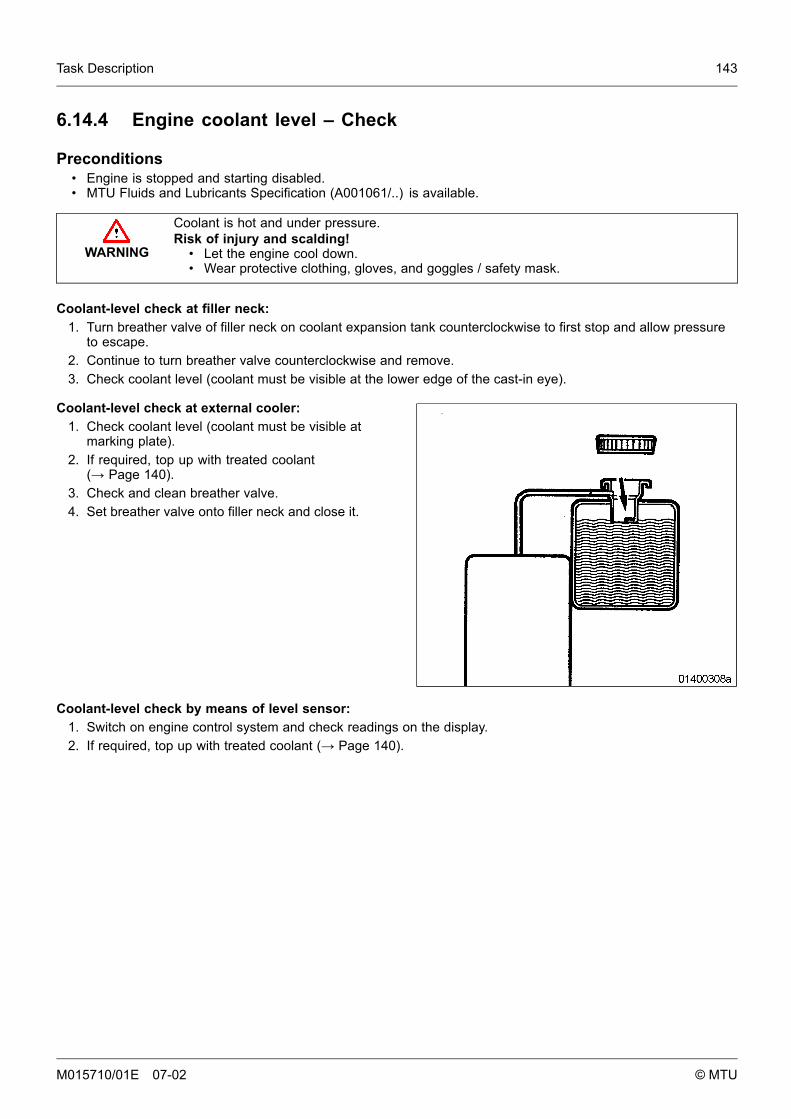
Task Description 143
6.14.4 Engine coolant level – Check
Preconditions• Engine is stopped and starting disabled.• MTU Fluids and Lubricants Specification (A001061/..) is available.
WARNING
Coolant is hot and under pressure.Risk of injury and scalding!
• Let the engine cool down.• Wear protective clothing, gloves, and goggles / safety mask.
Coolant-level check at filler neck:1. Turn breather valve of filler neck on coolant expansion tank counterclockwise to first stop and allow pressure
to escape.2. Continue to turn breather valve counterclockwise and remove.3. Check coolant level (coolant must be visible at the lower edge of the cast-in eye).
Coolant-level check at external cooler:1. Check coolant level (coolant must be visible at
marking plate).2. If required, top up with treated coolant
(→ Page 140).3. Check and clean breather valve.4. Set breather valve onto filler neck and close it.
Coolant-level check by means of level sensor:1. Switch on engine control system and check readings on the display.2. If required, top up with treated coolant (→ Page 140).
M015710/01E 07-02 © MTU
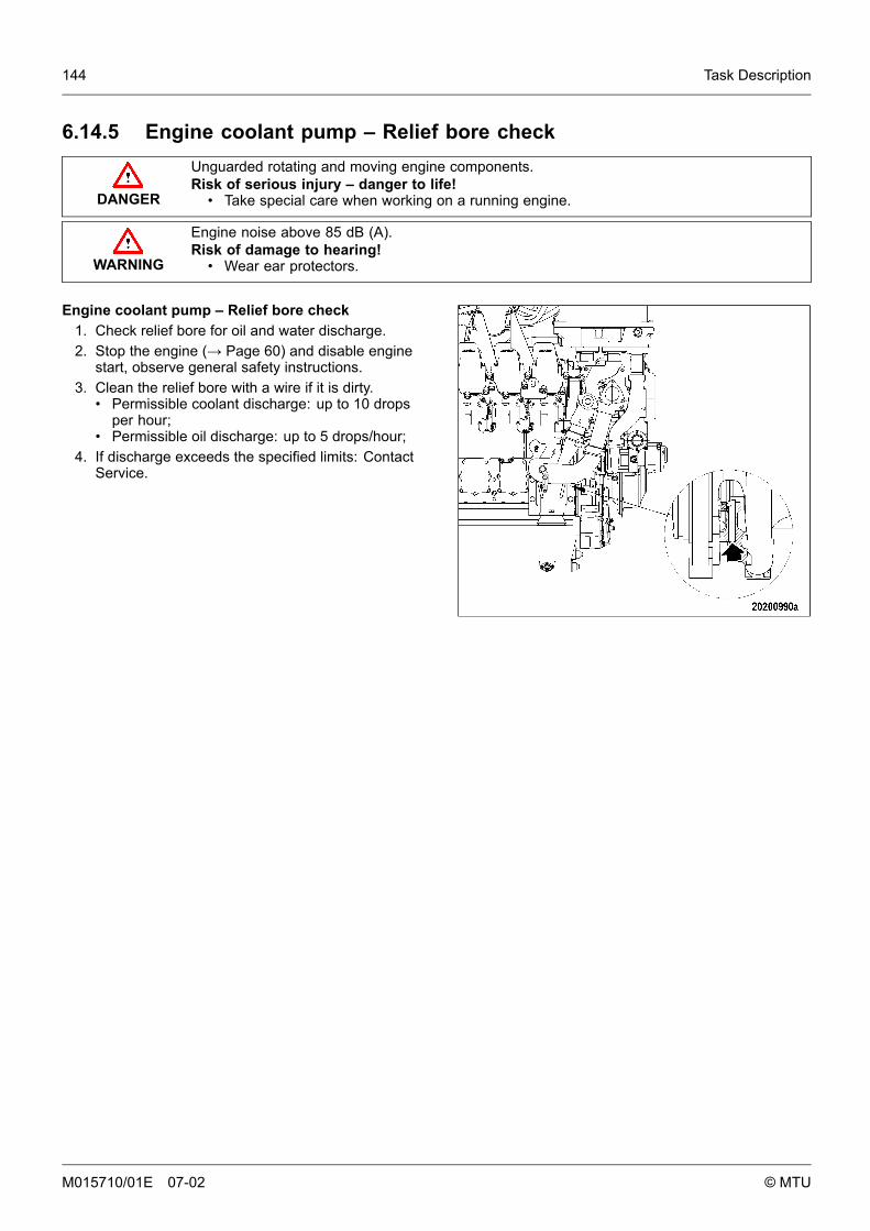
144 Task Description
6.14.5 Engine coolant pump – Relief bore check
DANGER
Unguarded rotating and moving engine components.Risk of serious injury – danger to life!
• Take special care when working on a running engine.
WARNING
Engine noise above 85 dB (A).Risk of damage to hearing!
• Wear ear protectors.
Engine coolant pump – Relief bore check1. Check relief bore for oil and water discharge.2. Stop the engine (→ Page 60) and disable engine
start, observe general safety instructions.3. Clean the relief bore with a wire if it is dirty.
• Permissible coolant discharge: up to 10 dropsper hour;
• Permissible oil discharge: up to 5 drops/hour;4. If discharge exceeds the specified limits: Contact
Service.
M015710/01E 07-02 © MTU
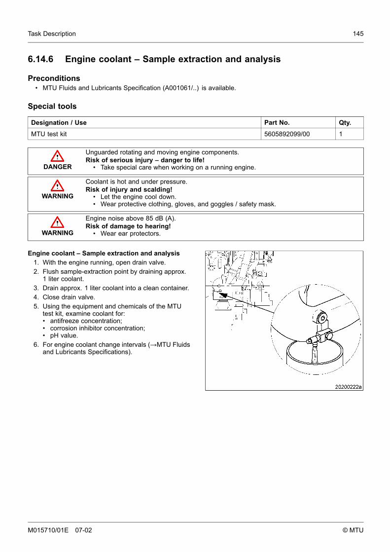
Task Description 145
6.14.6 Engine coolant – Sample extraction and analysis
Preconditions• MTU Fluids and Lubricants Specification (A001061/..) is available.
Special tools
Designation / Use Part No. Qty.
MTU test kit 5605892099/00 1
DANGER
Unguarded rotating and moving engine components.Risk of serious injury – danger to life!
• Take special care when working on a running engine.
WARNING
Coolant is hot and under pressure.Risk of injury and scalding!
• Let the engine cool down.• Wear protective clothing, gloves, and goggles / safety mask.
WARNING
Engine noise above 85 dB (A).Risk of damage to hearing!
• Wear ear protectors.
Engine coolant – Sample extraction and analysis1. With the engine running, open drain valve.2. Flush sample-extraction point by draining approx.
1 liter coolant.3. Drain approx. 1 liter coolant into a clean container.4. Close drain valve.5. Using the equipment and chemicals of the MTU
test kit, examine coolant for:• antifreeze concentration;• corrosion inhibitor concentration;• pH value.
6. For engine coolant change intervals (→MTU Fluidsand Lubricants Specifications).
M015710/01E 07-02 © MTU
146 Task Description
6.15 LT Circuit
6.15.1 Charge-air coolant change
Material
Designation / Use Part No. Qty.
Coolant
Drain charge-air coolant system (→ Page 149).
Fill charge-air coolant system (→ Page 147).
M015710/01E 07-02 © MTU

Task Description 147
6.15.2 Charge-air coolant – Filling
Preconditions• Engine is stopped and starting disabled.• MTU Fluids and Lubricants Specifications (A001061/..) are available.
Material
Designation / Use Part No. Qty.
Charge-air coolant
WARNING
Coolant is hot and under pressure.Risk of injury and scalding!
• Let the engine cool down.• Wear protective clothing, gloves, and goggles / safety mask.
CAUTION
Cold coolant in hot engine can cause thermal stress.Formation of cracks in components!
• Fill / top up coolant only into cold engine.
Preparatory steps1. Turn breather valve of coolant expansion tank
counterclockwise until the first stop and allowpressure to escape.
2. Continue to turn breather valve counterclockwiseand remove.
M015710/01E 07-02 © MTU

148 Task Description
Filling with charge-air coolant using pump1. Connect a suitable pump with a hose to the
drain valve (arrow).2. Open drain valve and pump coolant into engine
at 0.5 bar minimum.3. Fill expansion tank until overflow edge is reached.4. Close drain valve.5. Check proper condition of breather valve and
clean sealing faces if required.6. Place breather valve on filler neck and close.7. Start engine (→ Page 57).8. After the engine has run at unloaded condition for
10 seconds, stop engine (→ Page 60).9. Turn breather valve of coolant expansion tank
counterclockwise until the first stop and allowpressure to escape.
10. Continue to turn breather valve counterclockwiseand remove.
11. Check coolant level (→ Page 150) and top up ifrequired:11.1. Fill in coolant in expansion tank until the
coolant level at top edge of filler neckremains constant.
11.2. Place breather valve on filler neck and close.11.3. Repeat the steps from "Start engine" →
7. until coolant is no longer needed to betopped up.
11.4. Disconnect pump and hose.
Filling coolant through filler neck1. Alternatively: Fill in coolant in expansion tank until the coolant level at top edge of filler neck remains constant.2. Check proper condition of breather valve and clean sealing faces if required.3. Set breather valve onto filler neck and close until first stop is reached.4. Start engine (→ Page 57).5. After the engine has run at unloaded condition for 10 seconds, stop engine (→ Page 60).6. Turn breather valve counterclockwise and remove.7. Check coolant level (→ Page 150) and top up if required:
7.1. Repeat the steps from "Start engine" → 4. until coolant is no longer needed to be topped up.7.2. Check proper condition of breather valve and clean sealing faces if required.7.3. Place breather valve on filler neck and close.
Final steps1. Start the engine and operate it at unloaded condition for some minutes.2. Check coolant level (→ Page 150) and top up if required.
M015710/01E 07-02 © MTU
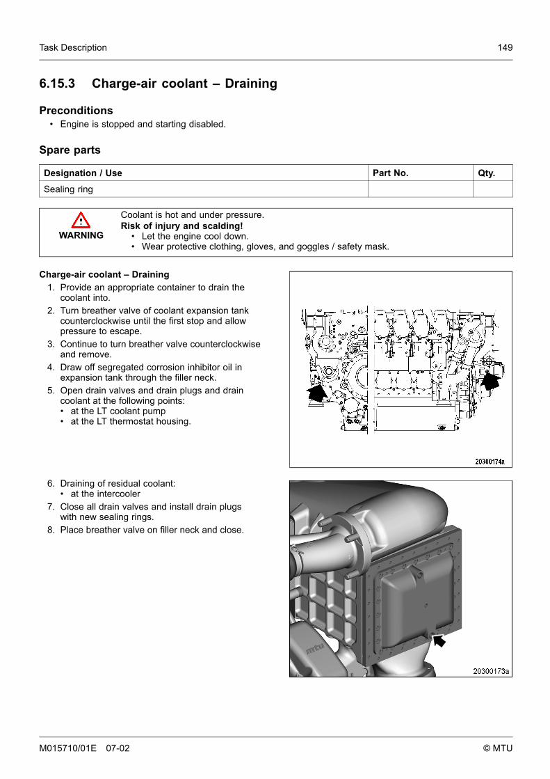
Task Description 149
6.15.3 Charge-air coolant – Draining
Preconditions• Engine is stopped and starting disabled.
Spare parts
Designation / Use Part No. Qty.
Sealing ring
WARNING
Coolant is hot and under pressure.Risk of injury and scalding!
• Let the engine cool down.• Wear protective clothing, gloves, and goggles / safety mask.
Charge-air coolant – Draining1. Provide an appropriate container to drain the
coolant into.2. Turn breather valve of coolant expansion tank
counterclockwise until the first stop and allowpressure to escape.
3. Continue to turn breather valve counterclockwiseand remove.
4. Draw off segregated corrosion inhibitor oil inexpansion tank through the filler neck.
5. Open drain valves and drain plugs and draincoolant at the following points:• at the LT coolant pump• at the LT thermostat housing.
6. Draining of residual coolant:• at the intercooler
7. Close all drain valves and install drain plugswith new sealing rings.
8. Place breather valve on filler neck and close.
M015710/01E 07-02 © MTU
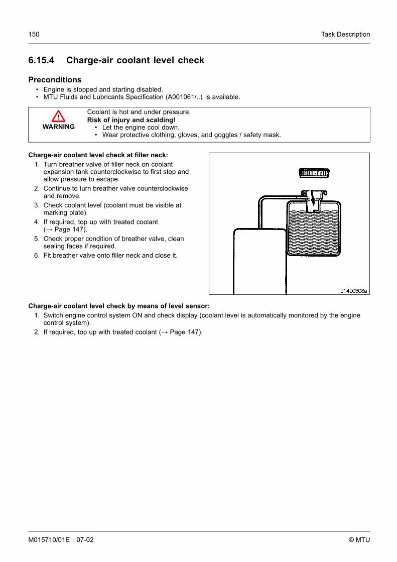
150 Task Description
6.15.4 Charge-air coolant level check
Preconditions• Engine is stopped and starting disabled.• MTU Fluids and Lubricants Specification (A001061/..) is available.
WARNING
Coolant is hot and under pressure.Risk of injury and scalding!
• Let the engine cool down.• Wear protective clothing, gloves, and goggles / safety mask.
Charge-air coolant level check at filler neck:1. Turn breather valve of filler neck on coolant
expansion tank counterclockwise to first stop andallow pressure to escape.
2. Continue to turn breather valve counterclockwiseand remove.
3. Check coolant level (coolant must be visible atmarking plate).
4. If required, top up with treated coolant(→ Page 147).
5. Check proper condition of breather valve, cleansealing faces if required.
6. Fit breather valve onto filler neck and close it.
Charge-air coolant level check by means of level sensor:1. Switch engine control system ON and check display (coolant level is automatically monitored by the engine
control system).2. If required, top up with treated coolant (→ Page 147).
M015710/01E 07-02 © MTU
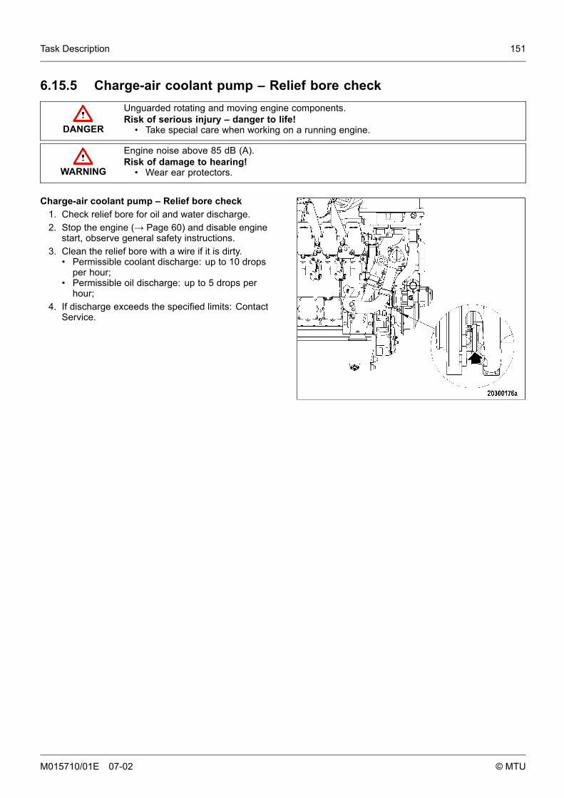
Task Description 151
6.15.5 Charge-air coolant pump – Relief bore check
DANGER
Unguarded rotating and moving engine components.Risk of serious injury – danger to life!
• Take special care when working on a running engine.
WARNING
Engine noise above 85 dB (A).Risk of damage to hearing!
• Wear ear protectors.
Charge-air coolant pump – Relief bore check1. Check relief bore for oil and water discharge.2. Stop the engine (→ Page 60) and disable engine
start, observe general safety instructions.3. Clean the relief bore with a wire if it is dirty.
• Permissible coolant discharge: up to 10 dropsper hour;
• Permissible oil discharge: up to 5 drops perhour;
4. If discharge exceeds the specified limits: ContactService.
M015710/01E 07-02 © MTU
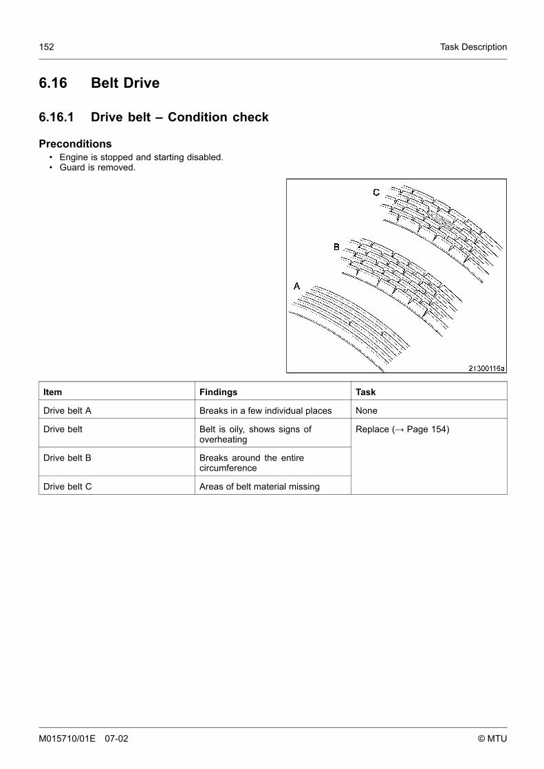
152 Task Description
6.16 Belt Drive
6.16.1 Drive belt – Condition check
Preconditions• Engine is stopped and starting disabled.• Guard is removed.
Item Findings Task
Drive belt A Breaks in a few individual places None
Drive belt Belt is oily, shows signs ofoverheating
Drive belt B Breaks around the entirecircumference
Drive belt C Areas of belt material missing
Replace (→ Page 154)
M015710/01E 07-02 © MTU
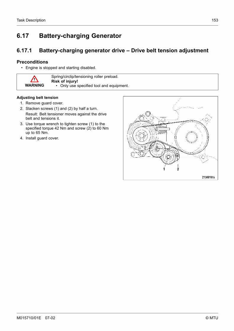
Task Description 153
6.17 Battery-charging Generator
6.17.1 Battery-charging generator drive – Drive belt tension adjustment
Preconditions• Engine is stopped and starting disabled.
WARNING
Spring/circlip/tensioning roller preload.Risk of injury!
• Only use specified tool and equipment.
Adjusting belt tension1. Remove guard cover.2. Slacken screws (1) and (2) by half a turn.
Result: Belt tensioner moves against the drivebelt and tensions it.
3. Use torque wrench to tighten screw (1) to thespecified torque 42 Nm and screw (2) to 60 Nmup to 65 Nm.
4. Install guard cover.
M015710/01E 07-02 © MTU
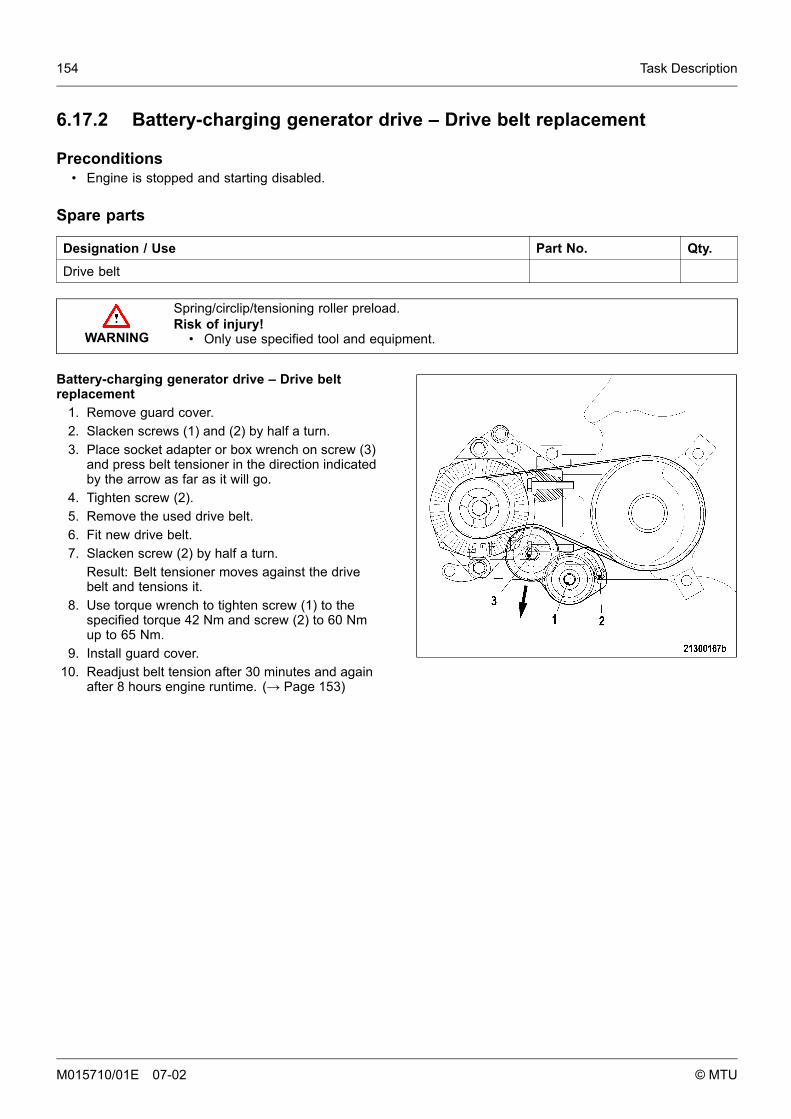
154 Task Description
6.17.2 Battery-charging generator drive – Drive belt replacement
Preconditions• Engine is stopped and starting disabled.
Spare parts
Designation / Use Part No. Qty.
Drive belt
WARNING
Spring/circlip/tensioning roller preload.Risk of injury!
• Only use specified tool and equipment.
Battery-charging generator drive – Drive beltreplacement
1. Remove guard cover.2. Slacken screws (1) and (2) by half a turn.3. Place socket adapter or box wrench on screw (3)
and press belt tensioner in the direction indicatedby the arrow as far as it will go.
4. Tighten screw (2).5. Remove the used drive belt.6. Fit new drive belt.7. Slacken screw (2) by half a turn.
Result: Belt tensioner moves against the drivebelt and tensions it.
8. Use torque wrench to tighten screw (1) to thespecified torque 42 Nm and screw (2) to 60 Nmup to 65 Nm.
9. Install guard cover.10. Readjust belt tension after 30 minutes and again
after 8 hours engine runtime. (→ Page 153)
M015710/01E 07-02 © MTU
Task Description 155
6.18 Cabling, General for Engine / Gearbox / Plant
6.18.1 Engine wiring – Check
Preconditions• Engine is stopped and starting disabled.
Material
Designation / Use Part No. Qty.
Isopropyl alcohol 46181 1
Engine wiring – Check1. Check securing screws of cable clamps on the engine and tighten loose screw connections.2. Make certain that cables are securely seated in clamps and cannot move freely.3. Check cable binders for secure seating, tighten loose cable binders.4. Replace defective cable binders.5. Inspect electrical components visually for damage:
• connector housings;• contacts;• connector sockets;• cables and terminals;• plug-in contacts.
6. If conductors are damaged, (→Contact Service).7. Clean dirty connector housings, sockets and contacts with isopropyl alcohol.
M015710/01E 07-02 © MTU
156 Task Description
6.19 Accessories for Engine Governor (Electronic) / ControlSystem
6.19.1 ECU and connectors – Cleaning
Preconditions• Engine is stopped and starting disabled.
Material
Designation / Use Part No. Qty.
Isopropyl alcohol
ECU and connectors – Cleaning1. Remove coarse dirt from housing surface using a cloth moistened with isopropyl alcohol.2. Remove dirt from connector and cable surfaces with isopropyl alcohol.3. Check legibility of cable labels. Clean or replace illegible labels.
Cleaning severely contaminated connectors on ECU1. Release latches of connectors and withdraw connectors.2. Clean connector housings, connector socket housings and all contacts with isopropyl alcohol.3. When connectors, sockets and all contacts are dry: Fit connectors and secure latches.
M015710/01E 07-02 © MTU
Task Description 157
6.19.2 ECU – Checking plug-in connections
Preconditions• Engine is stopped and starting disabled.
ECU – Checking plug-in connections1. Verify that all plug-in connections are securely seated.2. Secure loose connectors and latch.
M015710/01E 07-02 © MTU
158 Task Description
M015710/01E 07-02 © MTU

Special Tools 159
7 Special Tools
7.1 Special tools
Part No. Designation / Use Qty.
F6555766 Barring tool 1
F30006212 Ratchet 1
M015710/01E 07-02 © MTU
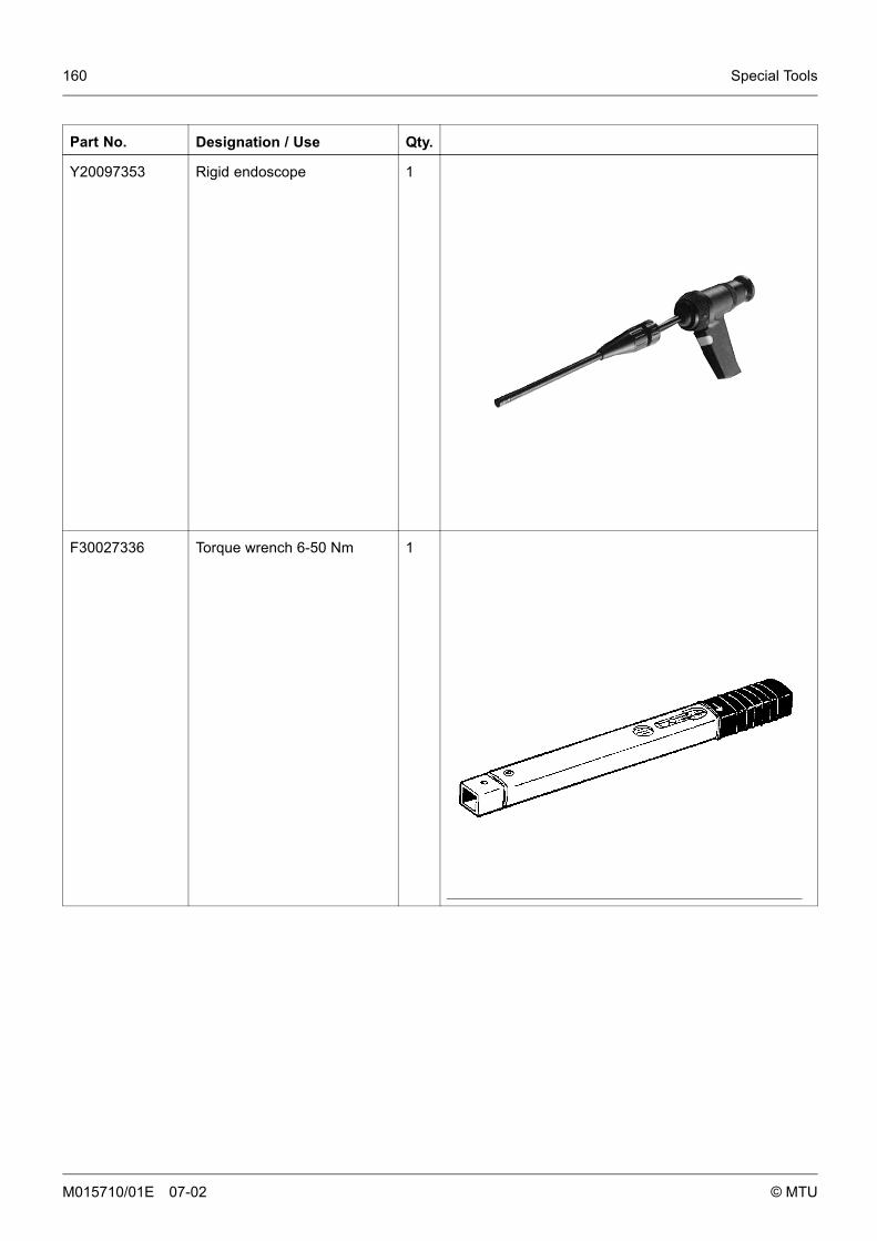
160 Special Tools
Part No. Designation / Use Qty.
Y20097353 Rigid endoscope 1
F30027336 Torque wrench 6-50 Nm 1
M015710/01E 07-02 © MTU
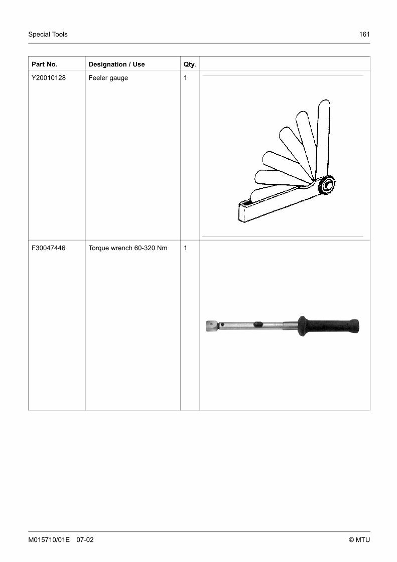
Special Tools 161
Part No. Designation / Use Qty.
Y20010128 Feeler gauge 1
F30047446 Torque wrench 60-320 Nm 1
M015710/01E 07-02 © MTU

162 Special Tools
Part No. Designation / Use Qty.
F30039526 Ring socket, 24 mm 1
F30510423 Torque wrench 10-60 Nm 1
M015710/01E 07-02 © MTU
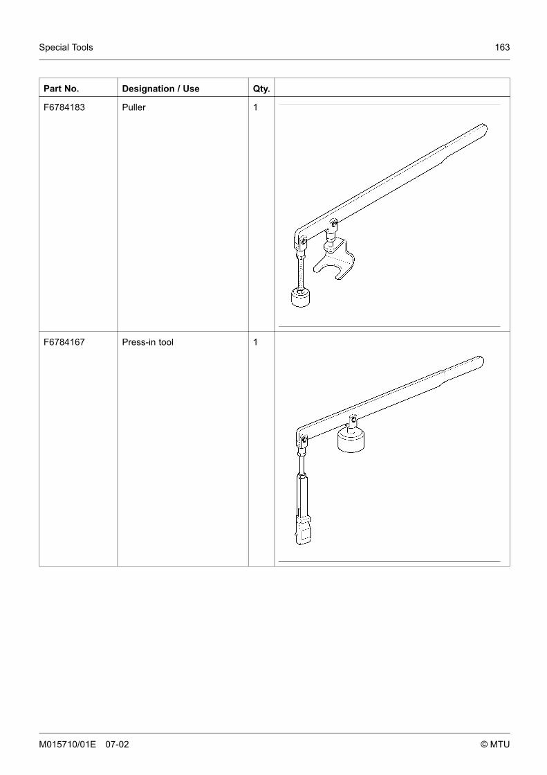
Special Tools 163
Part No. Designation / Use Qty.
F6784183 Puller 1
F6784167 Press-in tool 1
M015710/01E 07-02 © MTU
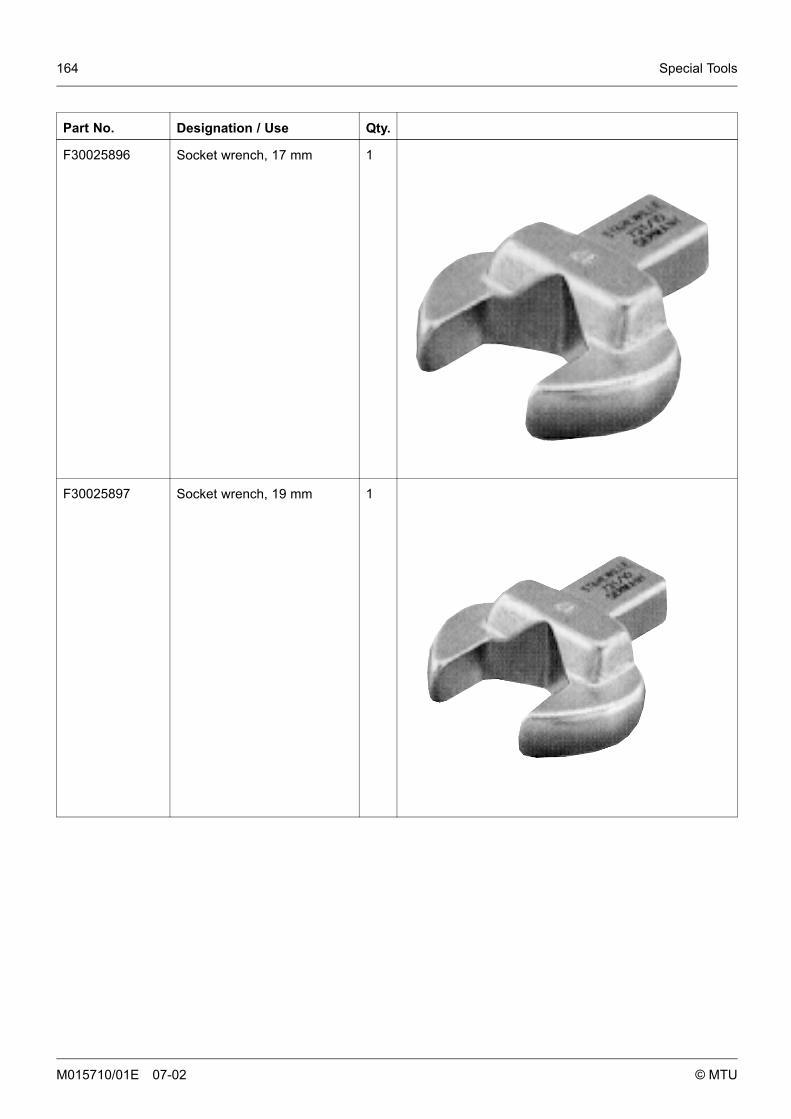
164 Special Tools
Part No. Designation / Use Qty.
F30025896 Socket wrench, 17 mm 1
F30025897 Socket wrench, 19 mm 1
M015710/01E 07-02 © MTU
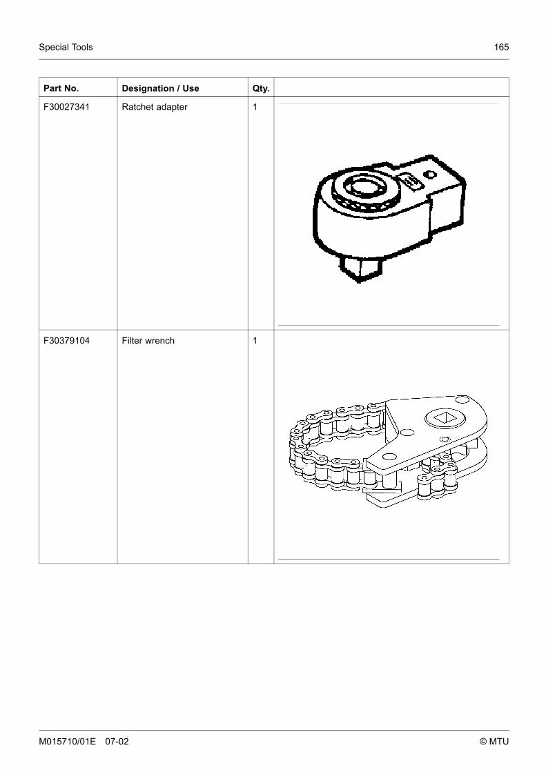
Special Tools 165
Part No. Designation / Use Qty.
F30027341 Ratchet adapter 1
F30379104 Filter wrench 1
M015710/01E 07-02 © MTU
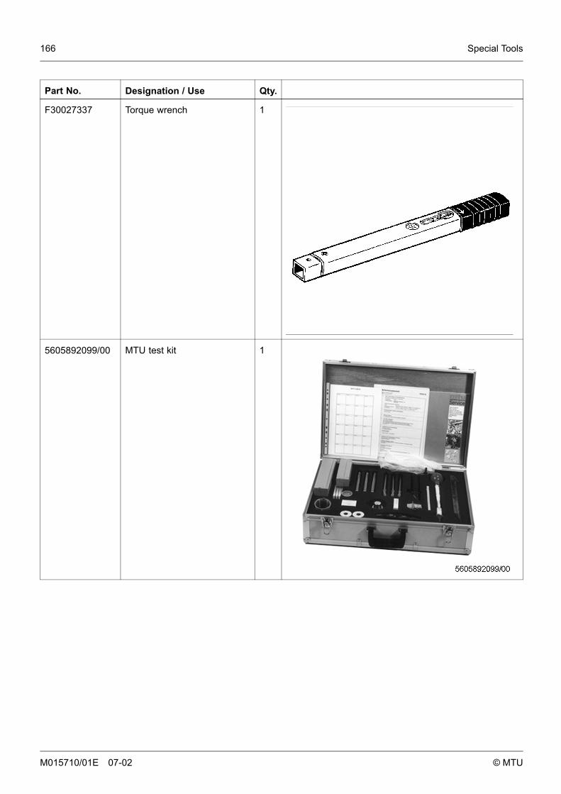
166 Special Tools
Part No. Designation / Use Qty.
F30027337 Torque wrench 1
5605892099/00 MTU test kit 1
M015710/01E 07-02 © MTU

Annex 167
8 Annex
8.1 Manufacturer’s documentationSee Manufacturer’s documentation.
M015710/01E 07-02 © MTU

168 Annex
8.2 MTU contact person/service partnerYou will find the MTU contact person/service partner for your region at www.mtu-online.com,worldwide, in the left-hand navigation margin.
M015710/01E 07-02 © MTU

Annex 169
8.3 Abbreviations
Abbreviation Meaning Explanation
A/D Analog/Digital Transformer: transforms sensor voltages intonumeric values
AFRS Air Filter Restriction Sensor
ANSI American National Standards Institute
ATL Abgasturbolader Exhaust turbocharger (ETC)
ATS Air Temperature Sensor
BR Baureihe Engine Series
CAN Controller Area Network
CEL Check Engine Light 1st function: Warning lamp (rectify fault as soonas possible)2nd function: Read out fault codes
CKT Circuit
CLS Coolant level sensor Monitors coolant level
CPS Coolant pressure sensor Monitors coolant pressure
CTS Coolant temperature sensor Monitors coolant temperature
DDEC Detroit Diesel Electronic Controls Engine control system made by Detroit Diesel
DDL Diagnostic Data Link
DDR Diagnostic Data Reader
DIN Deutsches Institut für Normung e. V. German Standardization Organization, at thesame time identifier of German standards("Deutsche Industrie-Norm")
DL Default Lost Alarm: Default CAN bus failure
DT Diagnostic Tool
ECM Electronic Control Module Electronic control unit of the DDEC system
ECU Engine Control Unit Engine governor
EDM Engine Data Module
EEPROM Electrically Erasable Programmable ReadOnly Memory
EFPA Electronic Foot Pedal Assembly
EGR Exhaust Gas Recirculation
EMU Engine Monitoring Unit
EUI Electronic Unit Injector
FLS Fluids and Lubricants Specification MTU Publication No. A01061/..
FPS Fuel Pressure Sensor Monitors fuel pressure
M015710/01E 07-02 © MTU
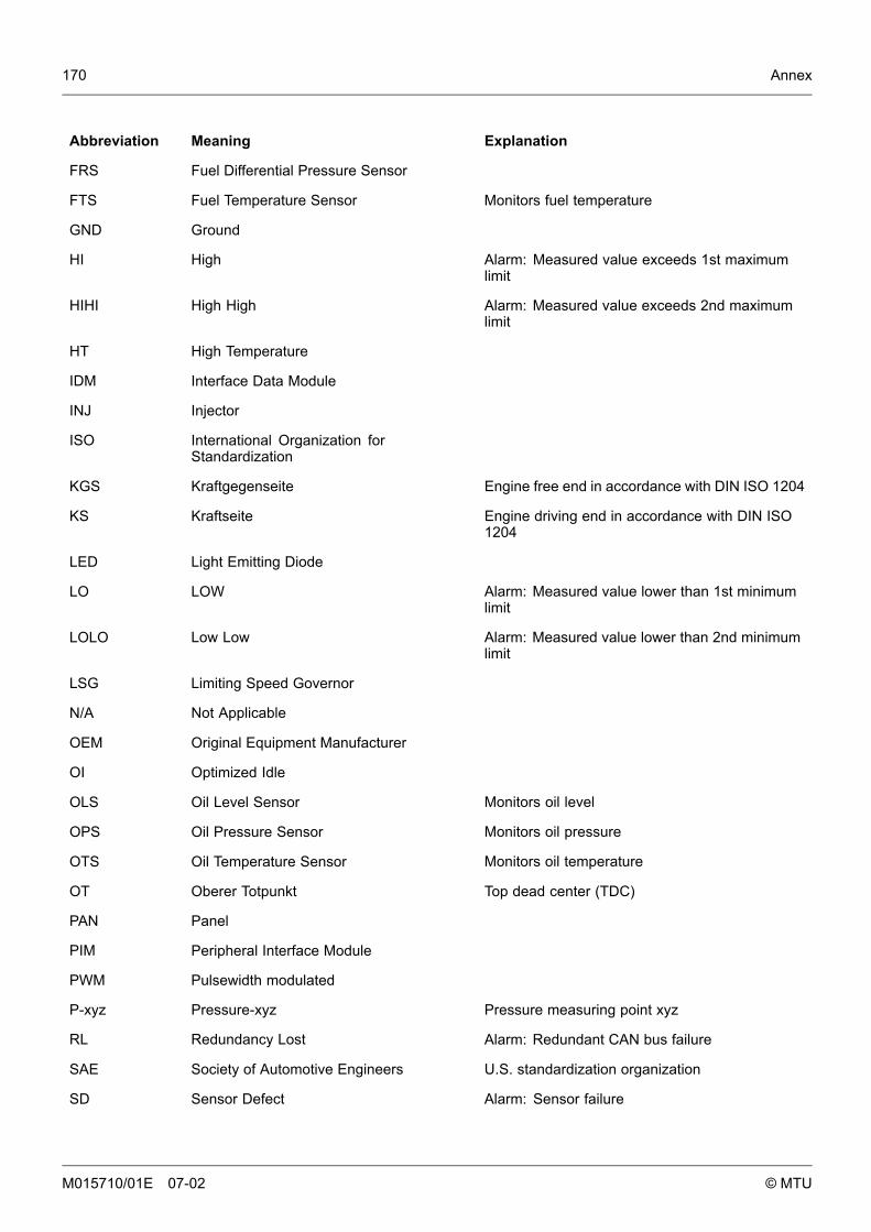
170 Annex
Abbreviation Meaning Explanation
FRS Fuel Differential Pressure Sensor
FTS Fuel Temperature Sensor Monitors fuel temperature
GND Ground
HI High Alarm: Measured value exceeds 1st maximumlimit
HIHI High High Alarm: Measured value exceeds 2nd maximumlimit
HT High Temperature
IDM Interface Data Module
INJ Injector
ISO International Organization forStandardization
KGS Kraftgegenseite Engine free end in accordance with DIN ISO 1204
KS Kraftseite Engine driving end in accordance with DIN ISO1204
LED Light Emitting Diode
LO LOW Alarm: Measured value lower than 1st minimumlimit
LOLO Low Low Alarm: Measured value lower than 2nd minimumlimit
LSG Limiting Speed Governor
N/A Not Applicable
OEM Original Equipment Manufacturer
OI Optimized Idle
OLS Oil Level Sensor Monitors oil level
OPS Oil Pressure Sensor Monitors oil pressure
OTS Oil Temperature Sensor Monitors oil temperature
OT Oberer Totpunkt Top dead center (TDC)
PAN Panel
PIM Peripheral Interface Module
PWM Pulsewidth modulated
P-xyz Pressure-xyz Pressure measuring point xyz
RL Redundancy Lost Alarm: Redundant CAN bus failure
SAE Society of Automotive Engineers U.S. standardization organization
SD Sensor Defect Alarm: Sensor failure
M015710/01E 07-02 © MTU
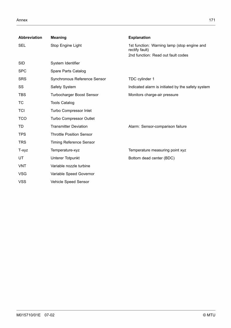
Annex 171
Abbreviation Meaning Explanation
SEL Stop Engine Light 1st function: Warning lamp (stop engine andrectify fault)2nd function: Read out fault codes
SID System Identifier
SPC Spare Parts Catalog
SRS Synchronous Reference Sensor TDC cylinder 1
SS Safety System Indicated alarm is initiated by the safety system
TBS Turbocharger Boost Sensor Monitors charge-air pressure
TC Tools Catalog
TCI Turbo Compressor Inlet
TCO Turbo Compressor Outlet
TD Transmitter Deviation Alarm: Sensor-comparison failure
TPS Throttle Position Sensor
TRS Timing Reference Sensor
T-xyz Temperature-xyz Temperature measuring point xyz
UT Unterer Totpunkt Bottom dead center (BDC)
VNT Variable nozzle turbine
VSG Variable Speed Governor
VSS Vehicle Speed Sensor
M015710/01E 07-02 © MTU

172 Annex
M015710/01E 07-02 © MTU
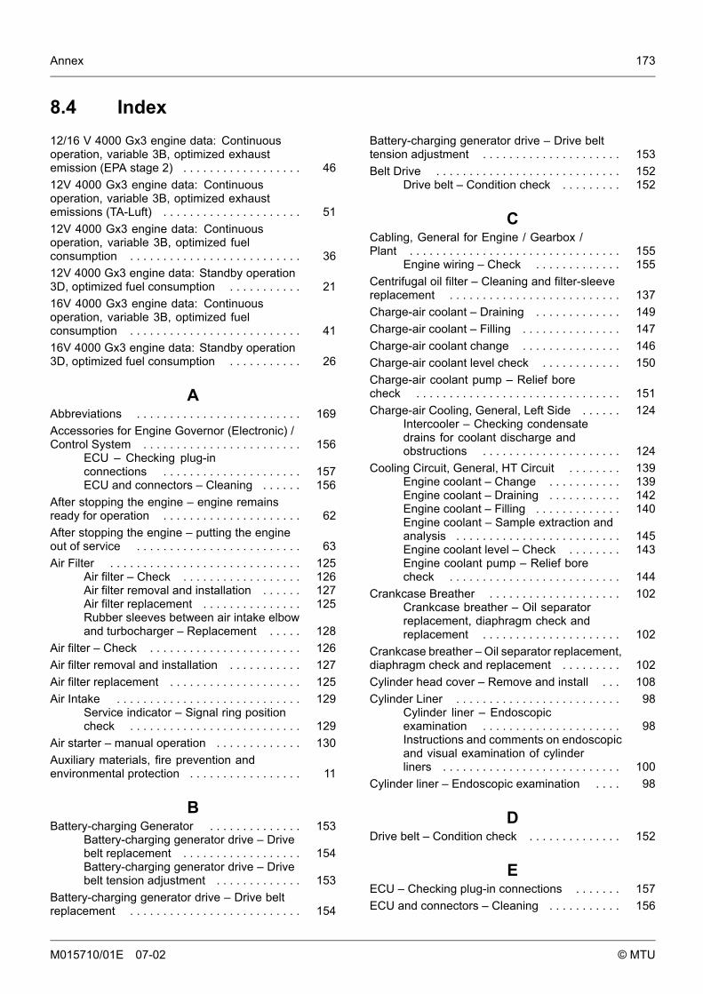
Annex 173
8.4 Index12/16 V 4000 Gx3 engine data: Continuousoperation, variable 3B, optimized exhaustemission (EPA stage 2) . . . . . . . . . . . . . . . . . . 4612V 4000 Gx3 engine data: Continuousoperation, variable 3B, optimized exhaustemissions (TA-Luft) . . . . . . . . . . . . . . . . . . . . . 5112V 4000 Gx3 engine data: Continuousoperation, variable 3B, optimized fuelconsumption . . . . . . . . . . . . . . . . . . . . . . . . . . 3612V 4000 Gx3 engine data: Standby operation3D, optimized fuel consumption . . . . . . . . . . . 2116V 4000 Gx3 engine data: Continuousoperation, variable 3B, optimized fuelconsumption . . . . . . . . . . . . . . . . . . . . . . . . . . 4116V 4000 Gx3 engine data: Standby operation3D, optimized fuel consumption . . . . . . . . . . . 26
AAbbreviations . . . . . . . . . . . . . . . . . . . . . . . . . 169Accessories for Engine Governor (Electronic) /Control System . . . . . . . . . . . . . . . . . . . . . . . . 156
ECU – Checking plug-inconnections . . . . . . . . . . . . . . . . . . . . . 157ECU and connectors – Cleaning . . . . . . 156
After stopping the engine – engine remainsready for operation . . . . . . . . . . . . . . . . . . . . . 62After stopping the engine – putting the engineout of service . . . . . . . . . . . . . . . . . . . . . . . . . 63Air Filter . . . . . . . . . . . . . . . . . . . . . . . . . . . . . 125
Air filter – Check . . . . . . . . . . . . . . . . . . 126Air filter removal and installation . . . . . . 127Air filter replacement . . . . . . . . . . . . . . . 125Rubber sleeves between air intake elbowand turbocharger – Replacement . . . . . 128
Air filter – Check . . . . . . . . . . . . . . . . . . . . . . . 126Air filter removal and installation . . . . . . . . . . . 127Air filter replacement . . . . . . . . . . . . . . . . . . . . 125Air Intake . . . . . . . . . . . . . . . . . . . . . . . . . . . . 129
Service indicator – Signal ring positioncheck . . . . . . . . . . . . . . . . . . . . . . . . . . 129
Air starter – manual operation . . . . . . . . . . . . . 130Auxiliary materials, fire prevention andenvironmental protection . . . . . . . . . . . . . . . . . 11
BBattery-charging Generator . . . . . . . . . . . . . . 153
Battery-charging generator drive – Drivebelt replacement . . . . . . . . . . . . . . . . . . 154Battery-charging generator drive – Drivebelt tension adjustment . . . . . . . . . . . . . 153
Battery-charging generator drive – Drive beltreplacement . . . . . . . . . . . . . . . . . . . . . . . . . . 154
Battery-charging generator drive – Drive belttension adjustment . . . . . . . . . . . . . . . . . . . . . 153Belt Drive . . . . . . . . . . . . . . . . . . . . . . . . . . . . 152
Drive belt – Condition check . . . . . . . . . 152
CCabling, General for Engine / Gearbox /Plant . . . . . . . . . . . . . . . . . . . . . . . . . . . . . . . . 155
Engine wiring – Check . . . . . . . . . . . . . 155Centrifugal oil filter – Cleaning and filter-sleevereplacement . . . . . . . . . . . . . . . . . . . . . . . . . . 137Charge-air coolant – Draining . . . . . . . . . . . . . 149Charge-air coolant – Filling . . . . . . . . . . . . . . . 147Charge-air coolant change . . . . . . . . . . . . . . . 146Charge-air coolant level check . . . . . . . . . . . . 150Charge-air coolant pump – Relief borecheck . . . . . . . . . . . . . . . . . . . . . . . . . . . . . . . 151Charge-air Cooling, General, Left Side . . . . . . 124
Intercooler – Checking condensatedrains for coolant discharge andobstructions . . . . . . . . . . . . . . . . . . . . . 124
Cooling Circuit, General, HT Circuit . . . . . . . . 139Engine coolant – Change . . . . . . . . . . . 139Engine coolant – Draining . . . . . . . . . . . 142Engine coolant – Filling . . . . . . . . . . . . . 140Engine coolant – Sample extraction andanalysis . . . . . . . . . . . . . . . . . . . . . . . . . 145Engine coolant level – Check . . . . . . . . 143Engine coolant pump – Relief borecheck . . . . . . . . . . . . . . . . . . . . . . . . . . 144
Crankcase Breather . . . . . . . . . . . . . . . . . . . . 102Crankcase breather – Oil separatorreplacement, diaphragm check andreplacement . . . . . . . . . . . . . . . . . . . . . 102
Crankcase breather – Oil separator replacement,diaphragm check and replacement . . . . . . . . . 102Cylinder head cover – Remove and install . . . 108Cylinder Liner . . . . . . . . . . . . . . . . . . . . . . . . . 98
Cylinder liner – Endoscopicexamination . . . . . . . . . . . . . . . . . . . . . 98Instructions and comments on endoscopicand visual examination of cylinderliners . . . . . . . . . . . . . . . . . . . . . . . . . . . 100
Cylinder liner – Endoscopic examination . . . . 98
DDrive belt – Condition check . . . . . . . . . . . . . . 152
EECU – Checking plug-in connections . . . . . . . 157ECU and connectors – Cleaning . . . . . . . . . . . 156
M015710/01E 07-02 © MTU
174 Annex
Emergency start (override mode) . . . . . . . . . . 58Emergency stop . . . . . . . . . . . . . . . . . . . . . . . 61Engine . . . . . . . . . . . . . . . . . . . . . . . . . . . . . . 95
Engine – Barring manually . . . . . . . . . . 95Engine – Barring with startingsystem . . . . . . . . . . . . . . . . . . . . . . . . . 96Engine test run . . . . . . . . . . . . . . . . . . . 97
Engine – Barring manually . . . . . . . . . . . . . . . 95Engine – Barring with starting system . . . . . . . 96Engine – Main dimensions . . . . . . . . . . . . . . . 18Engine coolant – Change . . . . . . . . . . . . . . . . 139Engine coolant – Draining . . . . . . . . . . . . . . . . 142Engine coolant – Filling . . . . . . . . . . . . . . . . . . 140Engine coolant – Sample extraction andanalysis . . . . . . . . . . . . . . . . . . . . . . . . . . . . . . 145Engine coolant level – Check . . . . . . . . . . . . . 143Engine coolant pump – Relief bore check . . . . 144Engine data 12/16V 4000 Gx3: Standbyoperation 3D, optimized exhaust emissions(EPA stage 2) . . . . . . . . . . . . . . . . . . . . . . . . . 31Engine governor ADEC (ECU 7) for Series 4000genset engines - Fault messages . . . . . . . . . . 74Engine layout . . . . . . . . . . . . . . . . . . . . . . . . . 15Engine Layout . . . . . . . . . . . . . . . . . . . . . . . . . 15
Engine layout . . . . . . . . . . . . . . . . . . . . 15Engine oil – Change . . . . . . . . . . . . . . . . . . . . 132Engine oil – Level check . . . . . . . . . . . . . . . . . 134Engine oil – Sample extraction andanalysis . . . . . . . . . . . . . . . . . . . . . . . . . . . . . . 135Engine oil filter – Replacement . . . . . . . . . . . . 136Engine side and cylinder designations . . . . . . 17Engine Side and Cylinder Designations . . . . . 17
Engine side and cylinderdesignations . . . . . . . . . . . . . . . . . . . . . 17
Engine test run . . . . . . . . . . . . . . . . . . . . . . . . 97Engine wiring – Check . . . . . . . . . . . . . . . . . . 155
FFinal compression pressure . . . . . . . . . . . . . . 20Final Compression Pressure . . . . . . . . . . . . . . 20
Final compression pressure . . . . . . . . . 20Firing order . . . . . . . . . . . . . . . . . . . . . . . . . . . 19Firing Order . . . . . . . . . . . . . . . . . . . . . . . . . . . 19
Firing order . . . . . . . . . . . . . . . . . . . . . . 19Fuel Filter . . . . . . . . . . . . . . . . . . . . . . . . . . . . 115
Fuel filter – Replacement . . . . . . . . . . . 115Fuel prefilter – differential pressure checkand adjustment of gauge . . . . . . . . . . . 117Fuel prefilter – draining . . . . . . . . . . . . . 118Fuel prefilter – filter elementreplacement . . . . . . . . . . . . . . . . . . . . . 122
Fuel prefilter – flushing . . . . . . . . . . . . . 120Fuel prefilter cleaning . . . . . . . . . . . . . . 116
Fuel filter – Replacement . . . . . . . . . . . . . . . . 115Fuel prefilter – differential pressure check andadjustment of gauge . . . . . . . . . . . . . . . . . . . . 117Fuel prefilter – draining . . . . . . . . . . . . . . . . . . 118Fuel prefilter – filter element replacement . . . . 122Fuel prefilter – flushing . . . . . . . . . . . . . . . . . . 120Fuel prefilter cleaning . . . . . . . . . . . . . . . . . . . 116Fuel System . . . . . . . . . . . . . . . . . . . . . . . . . . 114
Fuel system – Venting . . . . . . . . . . . . . 114Fuel system – Venting . . . . . . . . . . . . . . . . . . . 114
GGeneral conditions . . . . . . . . . . . . . . . . . . . . . 05
IIndex . . . . . . . . . . . . . . . . . . . . . . . . . . . . . . . . 173Injector . . . . . . . . . . . . . . . . . . . . . . . . . . . . . . 109
Injector – Removal and Installation . . . . 110Injector – Replacement . . . . . . . . . . . . . 109
Injector – Removal and Installation . . . . . . . . . 110Injector – Replacement . . . . . . . . . . . . . . . . . . 109Instructions and comments on endoscopic andvisual examination of cylinder liners . . . . . . . . 100Intercooler – Checking condensate drains forcoolant discharge and obstructions . . . . . . . . . 124
LLT Circuit . . . . . . . . . . . . . . . . . . . . . . . . . . . . . 146
Charge-air coolant – Draining . . . . . . . . 149Charge-air coolant – Filling . . . . . . . . . . 147Charge-air coolant change . . . . . . . . . . 146Charge-air coolant level check . . . . . . . 150Charge-air coolant pump – Relief borecheck . . . . . . . . . . . . . . . . . . . . . . . . . . 151
Lube-oil System, Lube-oil Circuit . . . . . . . . . . 132Engine oil – Change . . . . . . . . . . . . . . . 132Engine oil – Level check . . . . . . . . . . . . 134Engine oil – Sample extraction andanalysis . . . . . . . . . . . . . . . . . . . . . . . . . 135
MMain Engine Dimensions . . . . . . . . . . . . . . . . 18
Engine – Main dimensions . . . . . . . . . . 18Maintenance schedule matrix . . . . . . . . . . . . . 66Maintenance tasks . . . . . . . . . . . . . . . . . . . . . 68Manufacturer’s documentation . . . . . . . . . . . . 167MTU contact person/service partner . . . . . . . . 168
M015710/01E 07-02 © MTU
Annex 175
OOil Filtration/Cooling . . . . . . . . . . . . . . . . . . . . 136
Centrifugal oil filter – Cleaning andfilter-sleeve replacement . . . . . . . . . . . . 137Engine oil filter – Replacement . . . . . . . 136
Operational checks . . . . . . . . . . . . . . . . . . . . . 59
PPersonnel and organizational require-ments . . . . . . . . . . . . . . . . . . . . . . . . . . . . . . . 06Preface . . . . . . . . . . . . . . . . . . . . . . . . . . . . . . 65Putting the engine into operation after extendedout-of-service-periods (>3 months) . . . . . . . . . 55Putting the engine into operation after scheduledout-of-service-period . . . . . . . . . . . . . . . . . . . . 56
RRubber sleeves between air intake elbow andturbocharger – Replacement . . . . . . . . . . . . . 128
SSafety requirements when working on theengine . . . . . . . . . . . . . . . . . . . . . . . . . . . . . . . 08Service indicator – Signal ring positioncheck . . . . . . . . . . . . . . . . . . . . . . . . . . . . . . . 129Special tools . . . . . . . . . . . . . . . . . . . . . . . . . . 159Standards for warning notices in thepublication . . . . . . . . . . . . . . . . . . . . . . . . . . . 13Staring Equipment . . . . . . . . . . . . . . . . . . . . . 130
Air starter – manual operation . . . . . . . . 130Starter – Condition check . . . . . . . . . . . 131
Starter – Condition check . . . . . . . . . . . . . . . . 131Starting the engine in manual mode . . . . . . . . 57Stopping the engine in manual mode . . . . . . . 60
TTechnical Data . . . . . . . . . . . . . . . . . . . . . . . . 21
12/16 V 4000 Gx3 engine data:Continuous operation, variable 3B,optimized exhaust emission (EPA stage2) . . . . . . . . . . . . . . . . . . . . . . . . . . . . . 4612V 4000 Gx3 engine data: Continuousoperation, variable 3B, optimized exhaustemissions (TA-Luft) . . . . . . . . . . . . . . . . 5112V 4000 Gx3 engine data: Continuousoperation, variable 3B, optimized fuelconsumption . . . . . . . . . . . . . . . . . . . . . 3612V 4000 Gx3 engine data: Standbyoperation 3D, optimized fuelconsumption . . . . . . . . . . . . . . . . . . . . . 2116V 4000 Gx3 engine data: Continuousoperation, variable 3B, optimized fuelconsumption . . . . . . . . . . . . . . . . . . . . . 4116V 4000 Gx3 engine data: Standbyoperation 3D, optimized fuelconsumption . . . . . . . . . . . . . . . . . . . . . 26Engine data 12/16V 4000 Gx3: Standbyoperation 3D, optimized exhaustemissions (EPA stage 2) . . . . . . . . . . . . 31
Transport . . . . . . . . . . . . . . . . . . . . . . . . . . . . 07Troubleshooting . . . . . . . . . . . . . . . . . . . . . . . 71
VValve clearance – Check and adjustment . . . . 105Valve Drive . . . . . . . . . . . . . . . . . . . . . . . . . . . 104
Cylinder head cover – Remove andinstall . . . . . . . . . . . . . . . . . . . . . . . . . . 108Valve clearance – Check andadjustment . . . . . . . . . . . . . . . . . . . . . . 105Valve gear – Lubrication . . . . . . . . . . . . 104
Valve gear – Lubrication . . . . . . . . . . . . . . . . . 104
M015710/01E 07-02 © MTU

Related Documents