Manual Four Channel Relay Control Module Model 6525B Revision History File name / Revision Date Authors & Change Details Checked/ Approved Previous version BX 2004 RS/ JH MS Unidata Manual - 6525 4 Channel Relay Control Module User Manual Issue 2.0 2007 AB/CB/JH/MS/KC MS Unidata Manual - 6525 4 Channel Relay Control Module User Manual Issue 3.0 11 09 13 MP MS Unidata Manual - 6525B 4 Channel Relay Control Module Issue 4.0.docx 03 06 14 IM/CB Update MS Copyright © Unidata Pty Ltd 2000-2013. All rights reserved. No part of this publication may be reproduced, transmitted, transcribed, stored in a retrieval system, or translated into any spoken or computer language, in any form or by any means. Electronic, mechanical, magnetic, optical, chemical, manual or otherwise, without prior written permission of Unidata Pty Ltd 40 Ladner St, O’Connor Western Australia 6163.

Welcome message from author
This document is posted to help you gain knowledge. Please leave a comment to let me know what you think about it! Share it to your friends and learn new things together.
Transcript
Manual
Four Channel Relay Control Module
Model 6525B
Revision History
File name / Revision Date Authors & Change
Details Checked/ Approved
Previous version BX 2004 RS/ JH MS
Unidata Manual - 6525 4 Channel Relay Control Module User Manual Issue 2.0 2007 AB/CB/JH/MS/KC MS
Unidata Manual - 6525 4 Channel Relay Control Module User Manual Issue 3.0 11 09 13 MP MS
Unidata Manual - 6525B 4 Channel Relay Control Module Issue 4.0.docx 03 06 14 IM/CB Update MS
Copyright © Unidata Pty Ltd 2000-2013. All rights reserved. No part of this publication may be reproduced, transmitted, transcribed, stored in a retrieval system, or translated into any spoken or computer language, in any form or by any means. Electronic, mechanical, magnetic, optical, chemical, manual or otherwise, without prior written permission of Unidata Pty Ltd 40 Ladner St, O’Connor Western Australia 6163.

Manual – Four Channel Relay Control Module Model 6525B
Unidata Manual - 6525B 4 Channel Relay Control Module Issue 4.0.docx Contents 1
TABLE OF CONTENTS
1.0 Introduction ......................................................................................................................... 1
2.0 Controlling The Relays ....................................................................................................... 2 2.1 The High Speed Bi-Directional Serial Port .......................................................................... 2 2.2 Programming the Relays ..................................................................................................... 2
3.0 Connections ...................................................................................................................... 10
4.0 Specifications .................................................................................................................... 11
Manual – Four Channel Relay Control Module Model 6525B
Unidata Manual - 6525B 4 Channel Relay Control Module Issue 4.0.docx Page 1
1.0 INTRODUCTION
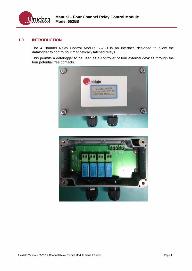
The 4-Channel Relay Control Module 6525B is an interface designed to allow the datalogger to control four magnetically latched relays.
This permits a datalogger to be used as a controller of four external devices through the four potential free contacts.

Manual – Four Channel Relay Control Module Model 6525B
Unidata Manual - 6525B 4 Channel Relay Control Module Issue 4.0.docx Page 2
2.0 CONTROLLING THE RELAYS
The 4 Channel Relay Control Module is controlled by the datalogger. The Logger provides power to the module as well as controlling the relays.
The scan synchronised power source provides power to the module. This source switches on with every scan.
Each relay is controlled by command from the datalogger using one of the high speed bi-directional serial ports. The commands sent from logger to 6525B module tells the module which relay(s) to activate. These commands are first interpreted by the module, then implemented when the logger sends a pulse to the module.
Note: If using an NRT logger with this device please make sure that the 5V regulated switched option on the field termination strip is provided (Model 2103E-S5)
2.1 The High Speed Bi-Directional Serial Port
The High Speed Serial Port consists of a DATA line and a CLOCK line. The CLOCK enables commands sent on the serial DATA line to be interpreted correctly by the module. Each logger scan, the serial ports are read. The Sync signal is used to indicate to the remote equipment that a logger read scan is about to begin. This signal is usually used to load the serial shift register(s) in the remote equipment in preparation of being read.
The Starlogger and Prologger offer two bi-directional serial data ports, DATA 0 and DATA 1.
CLOCK 0 should be used for DATA0 and CLOCK 1 should be used with DATA 1.
2.2 Programming the Relays
This section provides a simple example of how to program the relays. In some cases, the skills of an experienced programmer may be necessary.
In this example, two of the relays on the 4-Channel Relay Control Module are used to operate alarms when the water level of a river is either very high or very low. A Hydrostatic Water Depth Probe connected to a Starlogger is used to monitor water level in the river.
The Scheme: Every 5 seconds (scan rate) data from the probe is being sent to a Starlogger on Analog Channel 0 (a0).
Using the Starlog V4 create a Scheme which includes the above details.

Manual – Four Channel Relay Control Module Model 6525B
Unidata Manual - 6525B 4 Channel Relay Control Module Issue 4.0.docx Page 3
To create a scheme, select a Scheme Editor, New
Select logger that you intend to use (e.g.6004-2 512K Starlogger), select Instruments

Manual – Four Channel Relay Control Module Model 6525B
Unidata Manual - 6525B 4 Channel Relay Control Module Issue 4.0.docx Page 4
Select 6508x hydrostatic depth probe and 6525A instrument and Add
Manual – Four Channel Relay Control Module Model 6525B
Unidata Manual - 6525B 4 Channel Relay Control Module Issue 4.0.docx Page 5
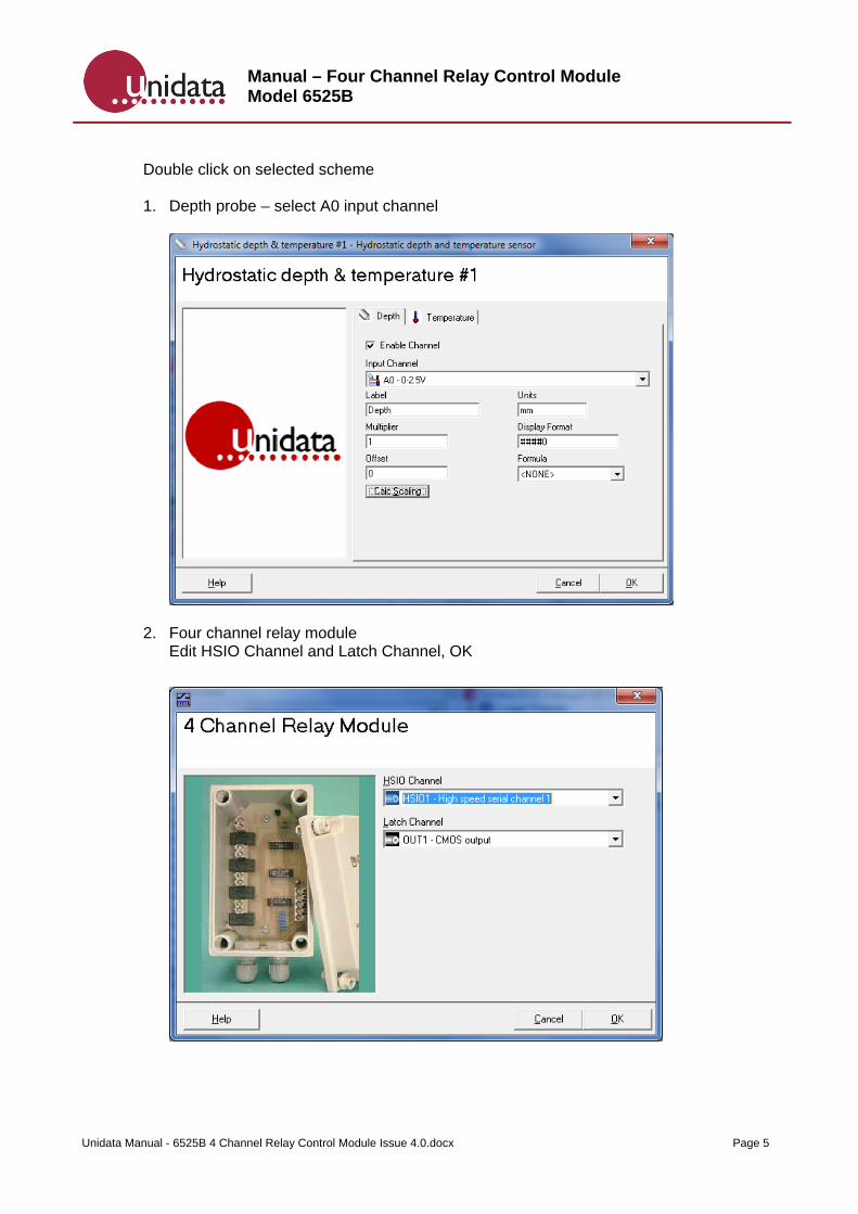
Double click on selected scheme 1. Depth probe – select A0 input channel
2. Four channel relay module Edit HSIO Channel and Latch Channel, OK

Manual – Four Channel Relay Control Module Model 6525B
Unidata Manual - 6525B 4 Channel Relay Control Module Issue 4.0.docx Page 6
Let’s say, the river height is usually approximately 50cm. If it drops to 25 cm, then the cattle will have to be moved into a paddock with a dam. On the other hand, if the river rises to 75 cm, then the pump will have to be relocated.
- When the probe measures 25 cm or less we want to trigger the LOW alarm. - When the probe reads 75 cm or higher we want to trigger the HIGH alarm.
Data from the water depth probe on analog channel 0 will be used to trigger the alarms. Therefore, the readings which will trigger the alarms are:
Label Actual Height As Read by Logger *
High 75 cm 191
Low 25 cm 63 * This is a value which corresponds to actual height on a scale from 0
In this example you will connect the High River alarm to Relay 1 and the Low River alarm to Relay 2. You will want Relay 1 to open when water level is 75cm or greater. This sets off the High River Alarm. Likewise, you will want Relay 2 to open when water level is 25cm or less. This sets off the Low River alarm.
To edit events select Events

Manual – Four Channel Relay Control Module Model 6525B
Unidata Manual - 6525B 4 Channel Relay Control Module Issue 4.0.docx Page 7
Select Add
Create “high” event as:
Note: depth probe measures depth in mm

Manual – Four Channel Relay Control Module Model 6525B
Unidata Manual - 6525B 4 Channel Relay Control Module Issue 4.0.docx Page 8
To switch high alarm off add another event as:
Select Add to create “low” event

Manual – Four Channel Relay Control Module Model 6525B
Unidata Manual - 6525B 4 Channel Relay Control Module Issue 4.0.docx Page 9
To switch low alarm off add another event as:
Save Scheme and program logger with the scheme
Manual – Four Channel Relay Control Module Model 6525B
Unidata Manual - 6525B 4 Channel Relay Control Module Issue 4.0.docx Page 10
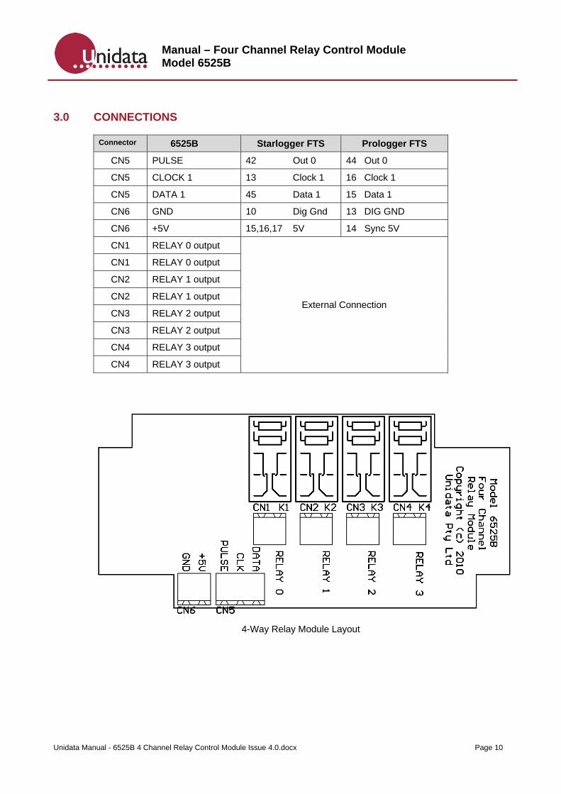
3.0 CONNECTIONS
Connector 6525B Starlogger FTS Prologger FTS
CN5 PULSE 42 Out 0 44 Out 0
CN5 CLOCK 1 13 Clock 1 16 Clock 1
CN5 DATA 1 45 Data 1 15 Data 1
CN6 GND 10 Dig Gnd 13 DIG GND
CN6 +5V 15,16,17 5V 14 Sync 5V
CN1 RELAY 0 output
External Connection
CN1 RELAY 0 output
CN2 RELAY 1 output
CN2 RELAY 1 output
CN3 RELAY 2 output
CN3 RELAY 2 output
CN4 RELAY 3 output
CN4 RELAY 3 output
4-Way Relay Module Layout
Manual – Four Channel Relay Control Module Model 6525B
Unidata Manual - 6525B 4 Channel Relay Control Module Issue 4.0.docx Page 11
4.0 SPECIFICATIONS
Dimensions: 110mm x 65mm x 55mm
Input: Programmable output control from Logger
Output: Potential free latched relay contact (DPDT)
Power Usage: 2mA max. Relay Contact
Ratings: 240V AC @ 0.5 A max.
Related Documents