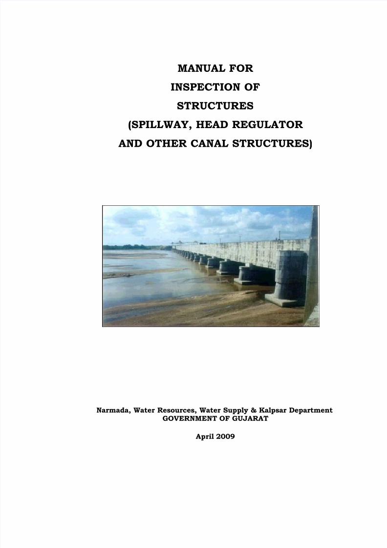
MANUAL FOR INSPECTION OF STRUCTURES (SPILLWAY, HEAD REGULATOR AND OTHER CANAL STRUCTURES) Narmada, Water Resources, Water Supply & Kalpsar Department GOVERNMENT OF GUJARAT April 2009

Welcome message from author
This document is posted to help you gain knowledge. Please leave a comment to let me know what you think about it! Share it to your friends and learn new things together.
Transcript
7/28/2019 Manual for Inspection of Structures
http://slidepdf.com/reader/full/manual-for-inspection-of-structures 1/156
MANUAL FOR
INSPECTION OF
STRUCTURES
(SPILLWAY, HEAD REGULATOR
AND OTHER CANAL STRUCTURES)
Narmada, Water Resources, Water Supply & Kalpsar DepartmentGOVERNMENT OF GUJARAT
April 2009
7/28/2019 Manual for Inspection of Structures
http://slidepdf.com/reader/full/manual-for-inspection-of-structures 2/156
Mission Statement
Harnessing the untapped waters of rivers for the survival
of millions of people and environmentally sound
sustainable development of Gujarat State by providing the
essence of life -- water and energy
Initial issue date: April 2009
Date of revision Outline of changes made
7/28/2019 Manual for Inspection of Structures
http://slidepdf.com/reader/full/manual-for-inspection-of-structures 3/156
1
Preface
Like any engineering work, structures i.e. dams and canal structuresrequire continual care and maintenance, first to ensure that they remainoperational and capable of performing all intended purposes and then
to preclude endangering people and property.
The safety of all canals is of considerable concern. Given that, theprinciple purpose of this Manual is to enhance the safety of dams andcanal structures.The purpose is to ensure adherence to approvedprocedures over long periods of time and during changes in operatingpersonnel.
The Manual is prepared primarily for the use of section officers incharge of various canals and canal structures who are assigned the
responsibility for the operation and maintenance of the canal.
THIS MANUAL CONTAINS, AS A MINIMUM, ALL INFORMATIONAND INSTRUCTIONS NECESSARY FOR SECTION OFFICERS TOPERFORM THEIR DUTIES.
The instructions provided in this manual are applicable to dams &canals of all sizes and types and are useful to all. The guidanceprovided is generally applicable to all situations. However, it isrecognised that the degree to which the methods and principles are
adopted will rest with the officer in charge of the dams & canals.
Manual for inspection of earthen embankments is also required to beread and operated simultaneously.
7/28/2019 Manual for Inspection of Structures
http://slidepdf.com/reader/full/manual-for-inspection-of-structures 4/156
2
C O N T E N T S
Chapter Page
1.
PART I
Inspecting the structures
(Spillway, HR & Canal structures)
PART II General Problems & Deficiencies
2. Common Material Problems
Cracks
Surface defects
Concrete deterioration
Metal problems
3. Obstructions
4. Displacement
5. Foundation and backfill problems
6. Seepage7. Poor Drainage
PART III Inspection of Structures8 Inspection of spillways/ wasteweirs/
escapes
9 Inspection of canal siphons
10 Inspection of drainage siphon
11 Inspection of HR (Outlet works) 12 Inspection of cross regulators
13 Inspection of falls
14 Inspection of aqeducts
7/28/2019 Manual for Inspection of Structures
http://slidepdf.com/reader/full/manual-for-inspection-of-structures 5/156
3
15.
PART IV
Schedule of Routine inspection
16.PART V
Inspection during emergency
7/28/2019 Manual for Inspection of Structures
http://slidepdf.com/reader/full/manual-for-inspection-of-structures 6/156
4
PART I
INSPECTING THE STRUCTURES(SPILLWAY, HR & CANAL STRUCTURES)
7/28/2019 Manual for Inspection of Structures
http://slidepdf.com/reader/full/manual-for-inspection-of-structures 7/156
5
Chapter 1
INSPECTING THE STRUCTURES (SPILLWAY, HR & OTHER
CANAL STRUCTURES)
1. Purpose
The purpose of inspection is to identify deficiencies that potentially
affect the safety of the structure. A deficiency is a condition that might
affect or interfere with the safety or operational effectiveness of the
structure.
2. Reviewing data
Review any available data about the structure before you begin your
inspection.An important aspect of inspection is tracking conditions and
potential problems to determine how and to what extent they are
changing over time.Historical and design information can alert you to
conditions and features that are of special concern and that should be
checked and documented.
Types of information that may be useful to review include:
• Design criteria
• Material data
• Construction records
• Records of operation
• Records of maintenance
• Previous inspection reports
• Manual of operation
7/28/2019 Manual for Inspection of Structures
http://slidepdf.com/reader/full/manual-for-inspection-of-structures 8/156
6
3. General Guidelines
When an inspection is conducted several things are required to be kept
in mind:
• The purpose of an inspection is to gather facts. Person inspecting
should probe for causes till he is satisfied.
• One should look for continuities or relationships among
deficiencies.
• All features of canal as well as structure should be inspected. No
shortcuts need to be taken. Enough time should be spent for
inspection. Particular attention should be paid to areas where
data indicate that change is occurring or where past deficiencies
have been noted.
• Person inspecting should know his limits and should consult
higher officers in case of doubt.
• SMPL rule should be observed for documenting conditions:
S Sketch the deficiency and note its important characteristics
M Measure the deficiency
P Photograph the deficiency/describe its characteristics in
writing
L Locate the deficiency relative to some standard reference
point
• Good notes should be taken; thorough records should be made.
•
Findings of inspection should be reported in form of precise reportimmediately after the inspection is over. This would be very much
useful at the time of subsequent inspections and also would help
evolve plan of action.

7/28/2019 Manual for Inspection of Structures
http://slidepdf.com/reader/full/manual-for-inspection-of-structures 9/156
7
4. Inspection tools and equipments:
Following outlines the tools and equipments that will be needed for
conducting inspection of canals and structures:
Binocular For sighting along top of bank, crest
Camera For recording conditionsRock hammer For sounding concrete/rock
Measuring tape For measurement
Probe For measuring width of crack at a depthPocket knife For scraping rock, scraping crevices/cracks
Shovel For clearing drains, manholes, pipesBucket and timer For measuring seepage & flow rates
Torch with cells For looking into pipes, conduits, barrelsJar For taking water samples, measuring turbidity
5. Spillways/ Escapes:
Observe the spillway/ escapes from the crest of waste weir. Walk along
the concrete sill noting any cracks, leaks, heaving or erosion etc. Check
the abutment-waste weir interface for any sign of erosion. Check walls
and floors as per checklist.
6. Head Regulator/ Outlets:
Observe the condition of the HR/ outlets at the upstream headwall. (In
order to view the outlet, it will be necessary to lower the water level in
the reservoir/canal. Prior to lowering, notify downstream operators.
Once the water level is lowered, the gate should be operated through
its full range as narrated in the "Guidelines for Operation &Maintenance " and also in the Standing Operating Procedure issued if
any, however, the gate must be closed for inspection of the waste
weir.)
7/28/2019 Manual for Inspection of Structures
http://slidepdf.com/reader/full/manual-for-inspection-of-structures 10/156
8
7. The downstream area:
Walk along the bed of the downstream channel and observe any
unusual conditions which may affect the performance of the dam/
canal, such as debris, vegetation, seepage, wet areas or excessive
sedimentation. Observe the lining, if any, to the channel to ensure that
they are intact and in good condition.
The inspection checklist included in this Manual should be copied and
completed every time a maintenance inspection is performed.
8. Inspecting the upstream face of structure
The upstream face should be inspected from the top of the wall,
abutments, Top of Bund of canal or a boat. The number of positions
from which you inspect the face depends on the length and height. It is
desirable that the water level in the reservoir/ canal is as low as
possible when you inspect the upstream face and that is the reason
why March inspection is most likely to give better chances of
inspection.
9. Under water inspection
In some instances it may be advisable to have a divers’ team inspect
the upstream face at a specific location below the waterline. This is a
special inspection technique that is used occasionally to determine the
cause or extent of a specific problem.
10 Inspecting the downstream face of structure
If leakage is occuring or if structural distress is evident, it will
most likely be found on the downstream face. It is best to inspect
downstram face with water in the dam/ canal at the highest waterlevel
7/28/2019 Manual for Inspection of Structures
http://slidepdf.com/reader/full/manual-for-inspection-of-structures 11/156
9
possible. This will increase your chances of seeing leakage on the
downstream face of the dam/ canal.
Pay particular attention to the toe of the structure where the structure
joins the foundation material as well as the junction of the structure with
the dam/ canal embankment.Look carefully for:
• Seepage along the toe
• Cracks• Alignment changes.
11. Special safety concerns when inspecting structures
The following safety issues are particularly important to the inspection
of spillway, HR & canal structures:
• Only persons who are physically fit should attempt a strenuousinspection task.
• Provide for communication between someone at the entranceand the person inspecting the inside of a structure.
• Poisonous snakes are a real threat in some parts.
• For an under water inspection, divers should be qualified in bothdiving and , if possible, diving inspection. Video may be provided
while carrying out under water inspection. Divers may be madeaware of the potential dangers near intake structures andentrance of HR,siphon barrels, such as cross currents, damage todiving equipment from sharp edges of metal or protruding bars
• When working around energy dissipators or on steep or slipperyslopes, inspecting person should be secured by ropes orharnesses.Water conveyance surfaces often have algae growththat can be particularly treacherous.
IMPORTANT INSPECTION TIP:If water is against the gates, make sure all controlequipment has been secured from operation or clearlymarked (red tagged) with warnings that personnel maybe injured if the equipment is operated. Be sure thatoperations and inspection personnel understand thesignificance of red-tag procedures.
7/28/2019 Manual for Inspection of Structures
http://slidepdf.com/reader/full/manual-for-inspection-of-structures 12/156
10
PART II
GENERAL PROBLEMS AND DEFICIENCIES
7/28/2019 Manual for Inspection of Structures
http://slidepdf.com/reader/full/manual-for-inspection-of-structures 13/156
11
CHAPTER 2
COMMON MATERIAL PROBLEMS
These include common problems observed in construction
material like concrete, metal, PVC water stops etc.
CONCRETE PROBLEMS COMMON IN STRUCTURES
1. Condition of concrete works is generally dependent on the
quality of materials used, circumstances or quality of
construction, and severity of weather exposure. Poor quality
materials and deficient composition of concrete and mortar willbe evidence by various forms of deterioration. Likewise, poor
quality construction, such as the use of too much of water in
mixes or finishing and/or permitting exposure to heat before
adequate curing and hardening of concrete or mortar, will lead
to early and accelerated concrete deterioration.
2. Expansion, contradiction, and construction joints and
pressure relief valves may be of concern when they become
"open" and permit seepage or leakage of water. Some opening or
closing of joints normally occurs with temperature changes.
3. All structures experience the entire range of possible concrete
problems, but conditions especially worthy of note are:
• Cracking
• Surface defects
• Concrete deterioration : Cavitation• Concrete deterioration : erosion
• Leaking Joints- Inadequate or damaged water stops- Other joint problems
7/28/2019 Manual for Inspection of Structures
http://slidepdf.com/reader/full/manual-for-inspection-of-structures 14/156
12
1. CRACKING :
4. All concrete is subject to cracking, which is usually the first
visible sign of concrete distress. You will see many cracks in thecourse of your inspections, and not all cracks are serious.
However, cracking should be monitored because cracks can
provide openings in the concrete that allow other types of
deficiencies to develop.
Characteristics of Cracks
5. Cracks in a concrete dam can be described in terms of several
characteristics: width, direction, depth, location, and trend
(change).
Length
6.Length is a self-evident concept. The length of a crack is
established by measurement.
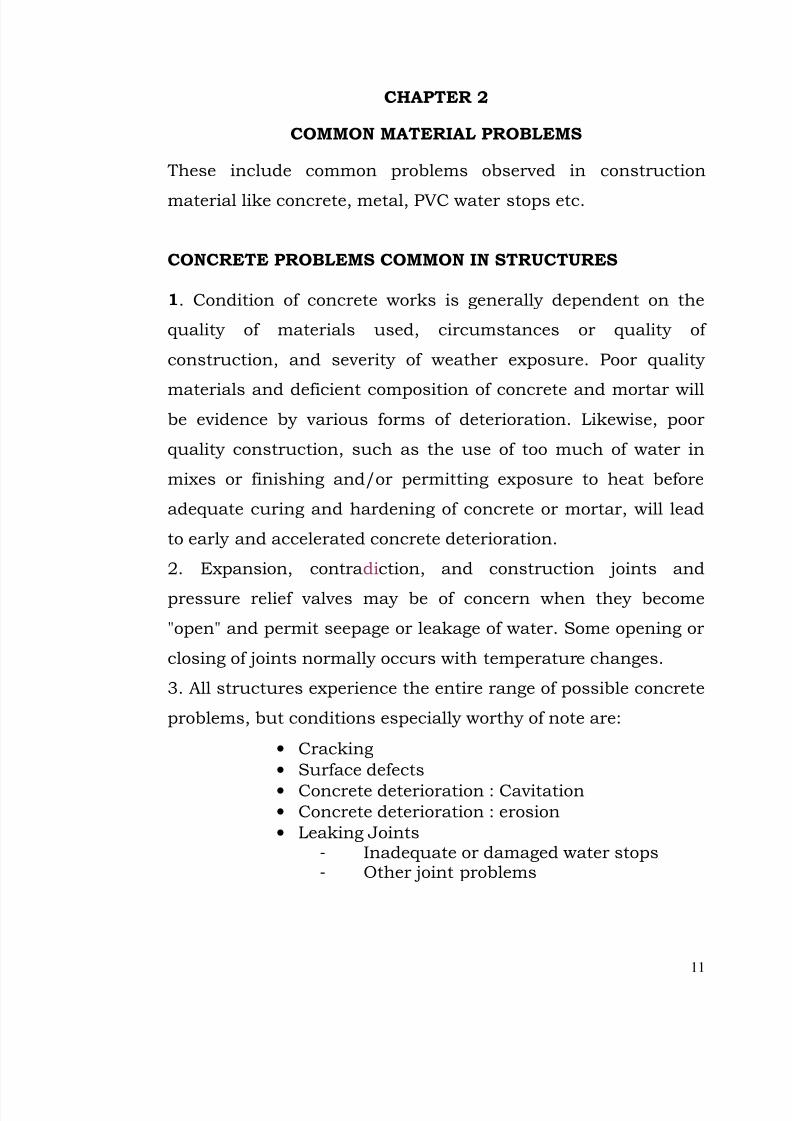
Width
FIGURE I. DETERMINING CRACK WIDTH
(Sectional View)
7/28/2019 Manual for Inspection of Structures
http://slidepdf.com/reader/full/manual-for-inspection-of-structures 15/156
13
7. The width of a crack is the amount of separation between the
two concrete parts. One common mistake made by some
inspectors is that they measure the width of a crack at the
surface, where deterioration of the concrete may exaggerate thetrue dimensions of the crack. Although surface deterioration
should be noted, it should not be included in an estimate of
crack width. If possible, you should measure or estimate crack
width at a depth below the surface deterioration by inserting a
probe such as a knife blade or wire. Figure 1 illustrates how to
determine the width of a crack.
Direction
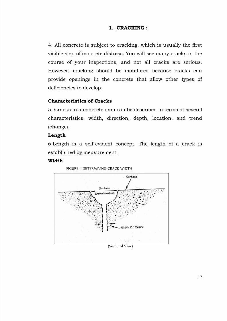
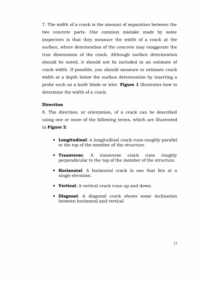
8. The direction, or orientation, of a crack can be described
using one or more of the following terms, which are illustrated
in Figure 2:
• Longitudinal: A longitudinal crack runs roughly parallelto the top of the member of the structure.
• Transverse: A transverse crack runs roughly perpendicular to the top of the member of the structure.
• Horizontal: A horizontal crack is one that lies at asingle elevation.
• Vertical: A vertical crack runs up and down.
•
Diagonal: A diagonal crack shows some inclinationbetween horizontal and vertical
7/28/2019 Manual for Inspection of Structures
http://slidepdf.com/reader/full/manual-for-inspection-of-structures 16/156
14
Cracking also can occur in random patterns (e.g., alligatorpattern) over the concrete surface.
FIGURE 2. ORIENTATION OF CRACKING
Depth
9. The full depth of a crack may be difficult to determine unless
the crack extends to another face or interior surface of the dam,
such as a chamber wall.
Trend
10. Trend is extremely important in monitoring cracking. The
trend of a crack is its history of change. Studying prior reports
before you begin an inspection will enable you to focus on how
cracks have changed--that is, whether they have become longer,
wider, or deeper, changed direction, or remained unchanged.Documenting any changes you observe will enable future
inspectors to do the same thing.
Location
11. Identifying the location of a given crack is vital to monitoring
7/28/2019 Manual for Inspection of Structures
http://slidepdf.com/reader/full/manual-for-inspection-of-structures 17/156
15
its trend in future inspections. Some of the reference
conventions are:
• Left and right facing downstream
• Block and joint numbers• Drain numbers
Other reference points are also useful:
• Stations (measured along the axis of the structure)
• Lift lines
• Elevation (on the downstream face)
• Measurements from any identifiable feature of thestructure (e.g.handrails, parapat)
Types of Cracks
12. Cracking in concrete structures generally falls into the
following four categories:
• Structural cracks
• Cracks along joints
• Shrinkage cracks
• Thermal cracking
• Pattern cracking
• D-Cracking
• Other Shallow Cracking
Structural Cracks
13. A potentially serious type of crack is the structural crack --
a crack that calls into question the structural integrity of an
element. Structural cracks are caused by the overstressing of portions of the sytucture because of extreme loading conditions,
inadequate design, poor construction techniques, or faulty
materials.
Often, structural cracks can be related to some feature of the
7/28/2019 Manual for Inspection of Structures
http://slidepdf.com/reader/full/manual-for-inspection-of-structures 18/156
16
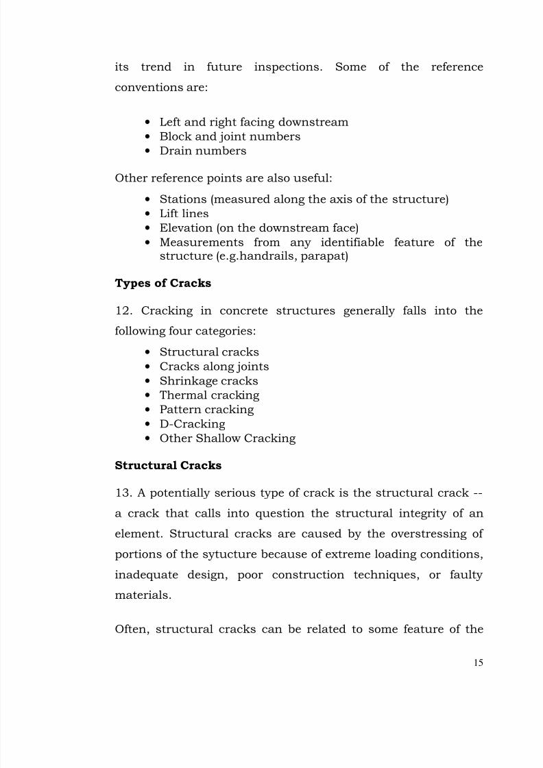
structure where stress concentrations occur--for example. . .
• The corner of an opening
• Areas of large temperature gradient
• Discontinuities in the foundation caused by material or
alignment changes or by differential movement infoundation or abutments
FIGURE 3 STRUCTURAL CRACK WITH VERTICAL DISPLACEMENT (Elevation View)
14. Structural cracks are often irregular; that is, they run at an
angle to the major axes of the member (say wall or column) and
they may change direction abruptly. These cracks are usually
wide and may be associated with noticeable displacement of the
concrete adjacent to the crack. The opening may tend to
increase as a result of continuous loading and creep of the
concrete. Figure 3 shows an irregular structural crack with
vertical displacement.
Cracks Along Joints
15. Cracking may occur along joints because of structural
movement, volumetric changes, or chemical reactions. Some of
these cracks are intentional and occur by design. Other cracks
along joints are not intentional and may pose a threat to the
7/28/2019 Manual for Inspection of Structures
http://slidepdf.com/reader/full/manual-for-inspection-of-structures 19/156
17
integrity of the structure. Document any new or worsening
cracks along joints, unless you are certain that these cracks are
there by design.
Shrinkage Cracks
16. When concrete is subjected to cycles of wetting and drying,
it expands and contracts. Volume changes occur during this
process and develop tensile stresses within the concrete,
causing cracking. Shrinkage cracks due to drying are generally
fine and show no evidence of movement. They are usually
shallow, but they can be several feet long.
17. Shrinkage cracks often occur soon after construction, as the
cement paste cures and shrinks. These cracks usually occur
shortly after construction and usually do not penetrate deeply
enough to be a threat.
Thermal Cracking
18. When concrete is placed in large sections, high tensile
stresses can result from the heat generated by the hydration of
cement, followed by differential cooling. When tensile stresses
exceed the tensile strength of the concrete, the concrete will
crack. Cracking due to thermal stresses is usually orthogonal
(rectangular) or blocky. Thermally induced cracks are generally
much deeper than shrinkage cracks.
19. Cracks also can be caused by temperature variations not
associated with construction. During cold weather, upper
portions of the darn may become colder than the lower portions
7/28/2019 Manual for Inspection of Structures
http://slidepdf.com/reader/full/manual-for-inspection-of-structures 20/156
18
that are in contact with the reservoir water. This temperature
difference can cause cracks to form, extending from the top
down each face of the strucyural member.
Pattern Cracking
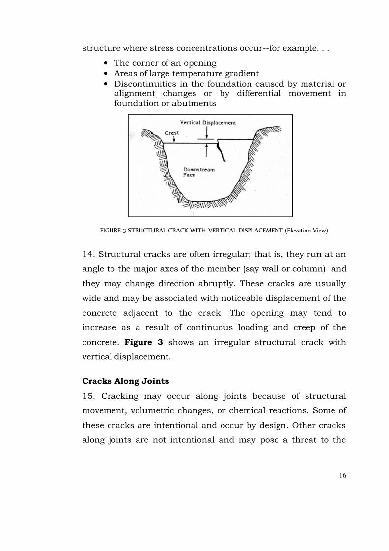
20 Pattern cracking is indicated by fine openings on concrete
surfaces in the form of a pattern. Pattern cracking results from
a decrease in volume of the material near the surface, or
increase in volume of the material below the surface, or both.
Figure 4 illustrates pattern cracking.
FIGURE 4 PATTERN CRACKING
21. Pattern cracks usually indicate a problem, such as freeze-
thaw action or some type of undesirable chemical reaction
occurring in the concrete. Chemical reactions will be discussed
in greater detail under concrete deterioration.
22. Freeze-thaw action occurs when water enters the pores,
cracks, or joints in the concrete. When the water freezes, it
expands and causes the concrete to crack. Water then can enter
7/28/2019 Manual for Inspection of Structures
http://slidepdf.com/reader/full/manual-for-inspection-of-structures 21/156
19
the new cracks and, when it freezes, cause the cracks to widen,
or spall at the surface.
D-Cracking
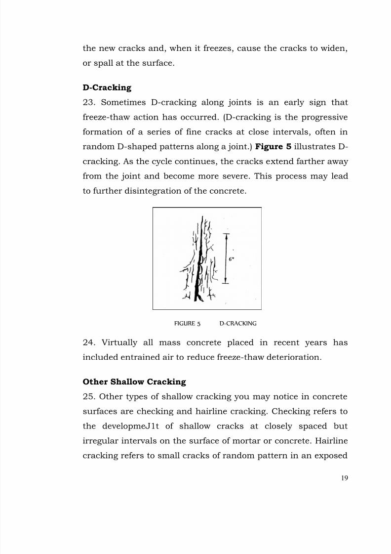
23. Sometimes D-cracking along joints is an early sign that
freeze-thaw action has occurred. (D-cracking is the progressive
formation of a series of fine cracks at close intervals, often in
random D-shaped patterns along a joint.) Figure 5 illustrates D-
cracking. As the cycle continues, the cracks extend farther away
from the joint and become more severe. This process may lead
to further disintegration of the concrete.
FIGURE 5 D-CRACKING
24. Virtually all mass concrete placed in recent years has
included entrained air to reduce freeze-thaw deterioration.
Other Shallow Cracking
25. Other types of shallow cracking you may notice in concrete
surfaces are checking and hairline cracking. Checking refers to
the developmeJ1t of shallow cracks at closely spaced but
irregular intervals on the surface of mortar or concrete. Hairline
cracking refers to small cracks of random pattern in an exposed
7/28/2019 Manual for Inspection of Structures
http://slidepdf.com/reader/full/manual-for-inspection-of-structures 22/156
7/28/2019 Manual for Inspection of Structures
http://slidepdf.com/reader/full/manual-for-inspection-of-structures 23/156
21
CRACK SURVEYS
27. A crack survey is an examination of a concrete structure for
the purpose of locating, recording, and identifying cracks and of noting the relationship of the cracks with other destructive
phenomena. Since cracking is often the first noticeable symptom
of concrete distress, a survey is a significant part of evaluating
the future serviceability of the structure. Some cracks may
occur early and not progress, while others may occur later and
increase in extent. Some may occur after an unusual event. A
design drawing or inspection drawing is often used to record the
location and extent of cracks in this type of survey.
28. A crack survey should identify-
• Characteristics of the cracks (length, width, direction,depth, and location)
• Descriptions of types
• Descriptions of other conditions or deficiencies thatmay be associated with cracking
Whenever feasible, external cracks should be correlated with
internal cracks. Where repairs have been made to the concrete,
crack surveys are difficult to perform and may be unreliable
because cracks beneath the repairs may indicate deficiencies at
greater depths. It is significant, however, to note whether newcracks have developed in the repair concrete. Such cracks may
indicate continued structural problems.
7/28/2019 Manual for Inspection of Structures
http://slidepdf.com/reader/full/manual-for-inspection-of-structures 24/156
22
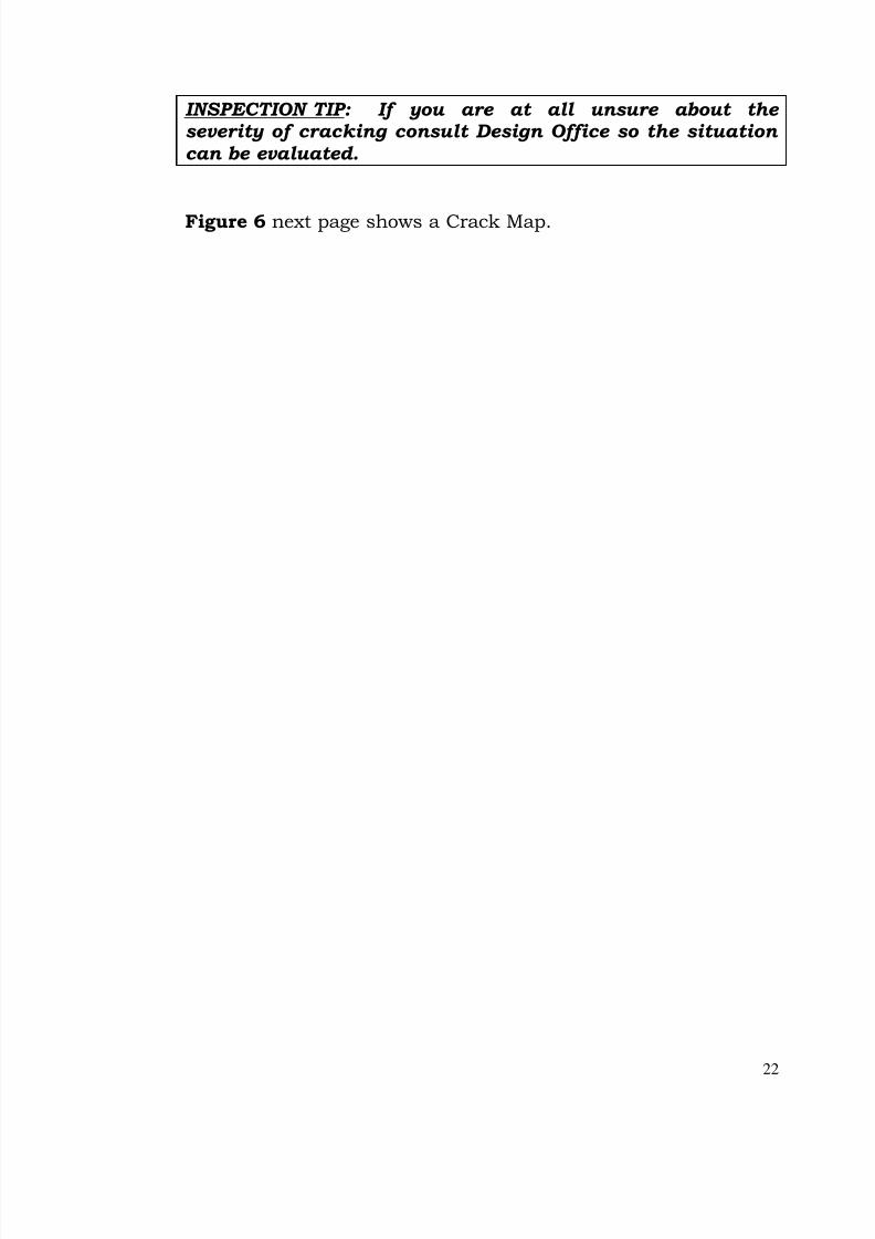
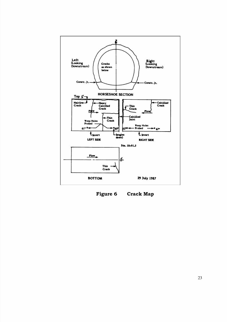
INSPECTION TIP: If you are at all unsure about the severity of cracking consult Design Office so the situation can be evaluated.
Figure 6 next page shows a Crack Map.
7/28/2019 Manual for Inspection of Structures
http://slidepdf.com/reader/full/manual-for-inspection-of-structures 25/156
23
Figure 6 Crack Map
7/28/2019 Manual for Inspection of Structures
http://slidepdf.com/reader/full/manual-for-inspection-of-structures 26/156
24
2. SURFACE DEFECTS
29. Surface defects are concrete deficiencies that are not
progressive in nature; that is they do not necessarily become
more extensive with time. They may include -
• Shallow deficiencies in the surface of the concrete.
• Textural defects resulting from improper constructiontechniques.
• Localized damage to the concrete surface.
If you observe surface defects in the concrete, you should-
• Record their nature and location.
• Note the need for prompt repair of defects that might leadto more extensive deterioration (e.g., by allowing water toenter the concrete mass).
Among the most common types of surface defects are
honeycombs, stratification, evidence of from slippage, stains and
impact drainage.
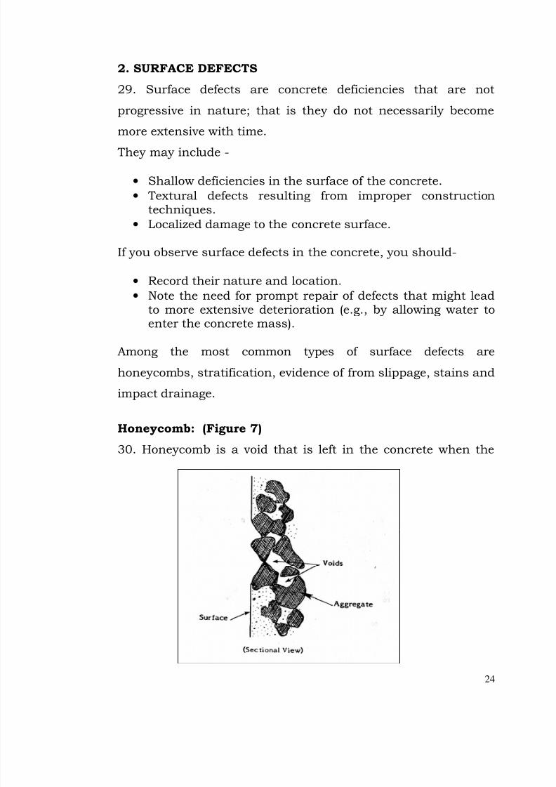
Honeycomb: (Figure 7)
30. Honeycomb is a void that is left in the concrete when the
7/28/2019 Manual for Inspection of Structures
http://slidepdf.com/reader/full/manual-for-inspection-of-structures 27/156
25
mortar fails to fill the spaces between the coarse aggregate
particles effectively. Honeycomb is caused by poor construction
practices, such as inadequate concrete mixing, segregation due
to improper placement practices, or inadequate vibration afterplacement in the forms.
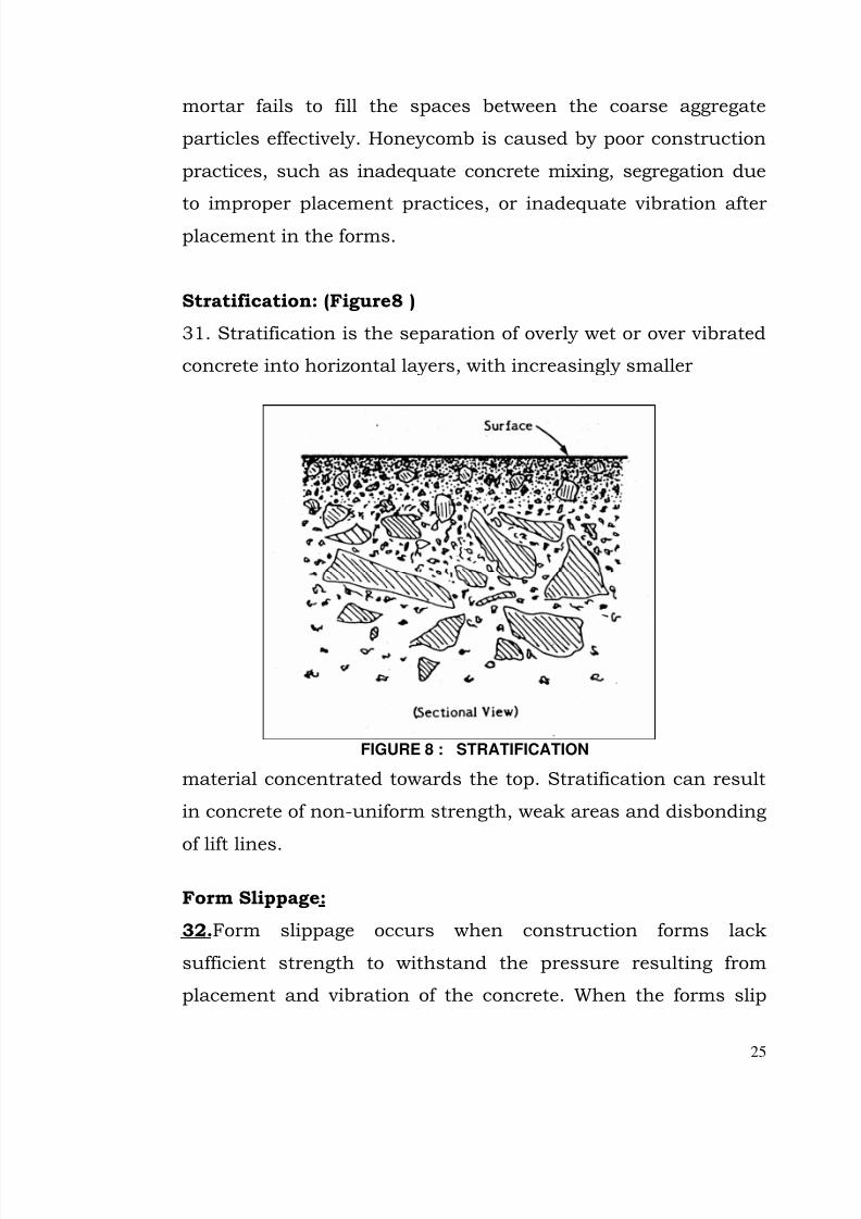
Stratification: (Figure8 )
31. Stratification is the separation of overly wet or over vibrated
concrete into horizontal layers, with increasingly smaller
FIGURE 8 : STRATIFICATION
material concentrated towards the top. Stratification can result
in concrete of non-uniform strength, weak areas and disbonding
of lift lines.
Form Slippage:
32.Form slippage occurs when construction forms lack
sufficient strength to withstand the pressure resulting from
placement and vibration of the concrete. When the forms slip
7/28/2019 Manual for Inspection of Structures
http://slidepdf.com/reader/full/manual-for-inspection-of-structures 28/156
26
during construction, they can produce slightly off set blocks and
uneven joints and surfaces. Sometimes form slippage is
mistaken for misalignment of the concrete, which usually occurs
well after construction.
Stains:
33. Although discoloration and staining sometimes are
associated with deterioration of concrete, most stains on
concrete surfaces cause only an unpleasant appearance rather
than damage. Stains may have natural causes, such as deposits
from runoff water of deposits from corrosion of exterior steel. They may also result from construction or maintenance
accidents (e.g. oil, grease, paint, creosote or asphalt).
Imapct Damage:
34. For example, the impact of a truck, boat, or crane, or rock
thrown into chutes can mar or chip away a portion of the
concrete surface. While such damage is localized, it can lead toother damage, such as freeze thaw action, by permitting
moisture to enter the concrete.
SURFACE DEFECTS : INSPECTION ACTIONS.
35. Unlike cracks, which may penetrate well into the concrete,
surface defects usually are shallow and do not usually present
an immediate threat to the structure. However, by erecting an
opening to weather and other forces, they can lead to other more
significant deterioration.
If you observe surface defects in the concrete, you should …..
7/28/2019 Manual for Inspection of Structures
http://slidepdf.com/reader/full/manual-for-inspection-of-structures 29/156
27
• Record their nature and location (remember SMPL)
• Note the need for prompt repair of defects that might lead
to more extensive deterioration (e.g., by allowing water to
enter the concrete mass).
7/28/2019 Manual for Inspection of Structures
http://slidepdf.com/reader/full/manual-for-inspection-of-structures 30/156
28
3. CONCRETE DETERIORATION
36. Deterioration is any adverse change on the surface or in the
body of the concrete that is caused by separation of components
of the concrete.
Types of Deterioration
37. There are numerous observable conditions that can indicate
concrete deterioration. Cracks, which we have discussed at
some length, can be considered a specific type of deterioration,
and they are often associated with other types of deterioration.
The following are the most common types of concrete
deterioration that you are likely to encounter.
Disintegration
38. Disintegration is deterioration of concrete into small
particles, or crumbling, due to any cause.
Spalling
39. Spalling is the loss of chunks of concrete from a surface,
usually because of compression, impact, or abrasion. Spalling
often occurs at the edges of concrete (e.g., along cracks, joints,
and corners or next to embedded objects). Figure 1, presented
earlier in this unit, showed a spall along a crack. Spalling may
have various causes:
• A blow to the concrete
• Action of weather
• Internal pressure (e.g., from a corroded rebar near thesurface)
• Expansion within the concrete mass
7/28/2019 Manual for Inspection of Structures
http://slidepdf.com/reader/full/manual-for-inspection-of-structures 31/156
29
Although spalls themselves are confined to the surface of the
concrete and thus may not be a serious problem, spalling can
lead to secondary problems. For example, spalling may expose
reinforcement, create a seepage path around an embeddedwaterstop at a joint, create an offset along the flow surface, or
develop into a point of structural weakness.
Efflorescence
40.Efflorescence is a deposit of salts from within the concrete
that forms on the surface. Efflorescence is caused by water
leaking through joints and cracks, leaching calcium hydroxideor carbonate from the cement, and carrying it to the exposed
surface. As the water evaporates, a hard, white calcium deposit
forms on the surface.
As calcium is leached from the concrete around the joint, the
opening may widen. This in turn leads to increased leakage and
faster deterioration. It should be noted, however, that leachingalso can be a self-healing process. In some cases the calcium
may be deposited in such a way around the joint that it seals
the opening against additional leakage.
Drummy Concrete
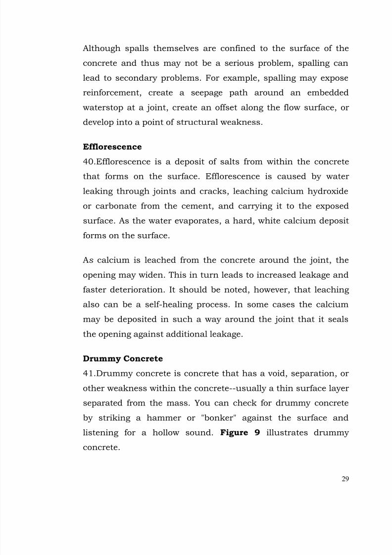
41.Drummy concrete is concrete that has a void, separation, or
other weakness within the concrete--usually a thin surface layer
separated from the mass. You can check for drummy concrete
by striking a hammer or "bonker" against the surface and
listening for a hollow sound. Figure 9 illustrates drummy
concrete.
7/28/2019 Manual for Inspection of Structures
http://slidepdf.com/reader/full/manual-for-inspection-of-structures 32/156
30
FIGURE 9. DRUMMY CONCRETE
(Elevation View)
Popouts
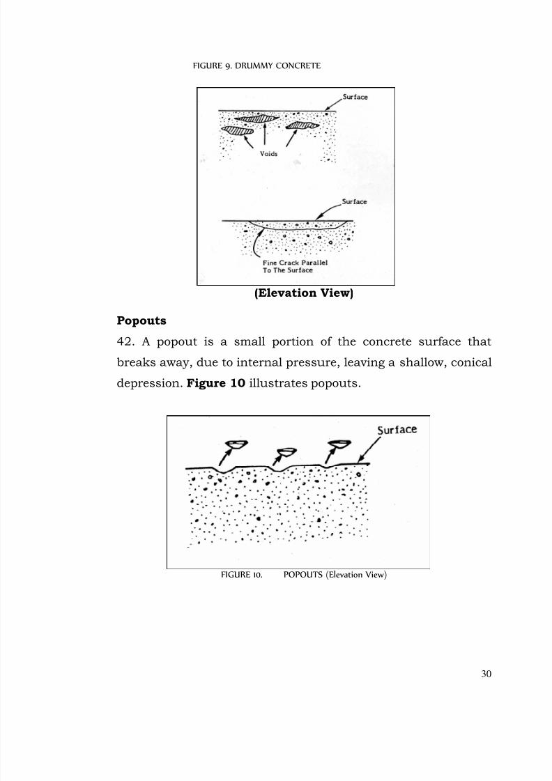
42. A popout is a small portion of the concrete surface that
breaks away, due to internal pressure, leaving a shallow, conical
depression. Figure 10 illustrates popouts.
FIGURE 10. POPOUTS (Elevation View)
7/28/2019 Manual for Inspection of Structures
http://slidepdf.com/reader/full/manual-for-inspection-of-structures 33/156
31
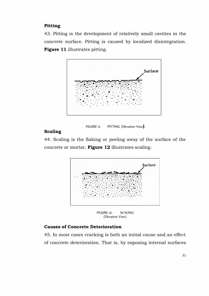
Pitting
43. Pitting is the development of relatively small cavities in the
concrete surface. Pitting is caused by localized disintegration.
Figure 11 illustrates pitting.
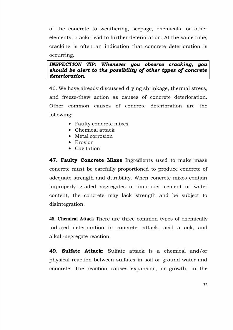
FIGURE 11. PITTING (Elevation View)Scaling
44. Scaling is the flaking or peeling away of the surface of the
concrete or mortar. Figure 12 illustrates scaling.
FIGURE 12. SCALING(Elevation View)
Causes of Concrete Deterioration
45. In most cases cracking is both an initial cause and an effect
of concrete deterioration. That is, by exposing internal surfaces
7/28/2019 Manual for Inspection of Structures
http://slidepdf.com/reader/full/manual-for-inspection-of-structures 34/156
32
of the concrete to weathering, seepage, chemicals, or other
elements, cracks lead to further deterioration. At the same time,
cracking is often an indication that concrete deterioration is
occurring.INSPECTION TIP: Whenever you observe cracking, you should be alert to the possibility of other types of concrete deterioration.
46. We have already discussed drying shrinkage, thermal stress,
and freeze-thaw action as causes of concrete deterioration.
Other common causes of concrete deterioration are the
following:
• Faulty concrete mixes
• Chemical attack
• Metal corrosion
• Erosion
• Cavitation
47. Faulty Concrete Mixes Ingredients used to make mass
concrete must be carefully proportioned to produce concrete of
adequate strength and durability. When concrete mixes contain
improperly graded aggregates or improper cement or water
content, the concrete may lack strength and be subject to
disintegration.
48. Chemical Attack There are three common types of chemically
induced deterioration in concrete: attack, acid attack, and
alkali-aggregate reaction.
49. Sulfate Attack: Sulfate attack is a chemical and/or
physical reaction between sulfates in soil or ground water and
concrete. The reaction causes expansion, or growth, in the
7/28/2019 Manual for Inspection of Structures
http://slidepdf.com/reader/full/manual-for-inspection-of-structures 35/156
33
concrete, which leads to disintegration. Concrete attacked by
sulfate is usually light in color and falls apart easily when
struck with a hammer. Other typical symptoms of sulfate i1 t
tack include. . .• Cracking
• Spalling
• Scaling
• Stains
50. Acid Attack: Acid attack is usually the result of bacterial
action on the calcium hydroxide found in hydrated Portland
cement, limestone, or dolomitic aggregates. In most cases, the
reaction results in leaching away of water-soluble compounds.
Symptoms of acid attack may include. . .
• Efflorescence
• Cracking
• Spalling
• Color change
Acidic water created by this reaction can also hasten corrosion
of embedded steel reinforcement. As the steel corrodes, internal
pressures develop, which may crack or spall adjacent concrete.
51. Alkali-Aggregate Reaction: An alkali-aggregate reaction is
an undesirable chemical reaction between cement and aggregate
that causes abnormal expansion and cracking. There are two
main kinds of alkali-aggregate reaction: alkali-carbonate
reaction and alkali-silica reaction. Early indicators include. . .
• Pattern cracking, usually concentrated in areas thatare exposed to moisture in a wet-dry cycle (e.g., piers,parapets, and the top of the structural member)
• Efflorescence
• Incrustation
7/28/2019 Manual for Inspection of Structures
http://slidepdf.com/reader/full/manual-for-inspection-of-structures 36/156
34
• White rings around aggregate particles
• A gel-like substance at pores, cracks, or openings inthe concrete (only for alkali-silica reactions)
Extreme alkali-aggregate reactions are characterized by closing
of expansion joints, hence the term growth of concrete is
sometimes used. Continued reaction can result in . . .
• Debonding of blocks at lift lines
• Binding of gates, valves, and metalwork
• Severe cracking
• Loss of strength and ultimate failure of the structureby sliding or overturning
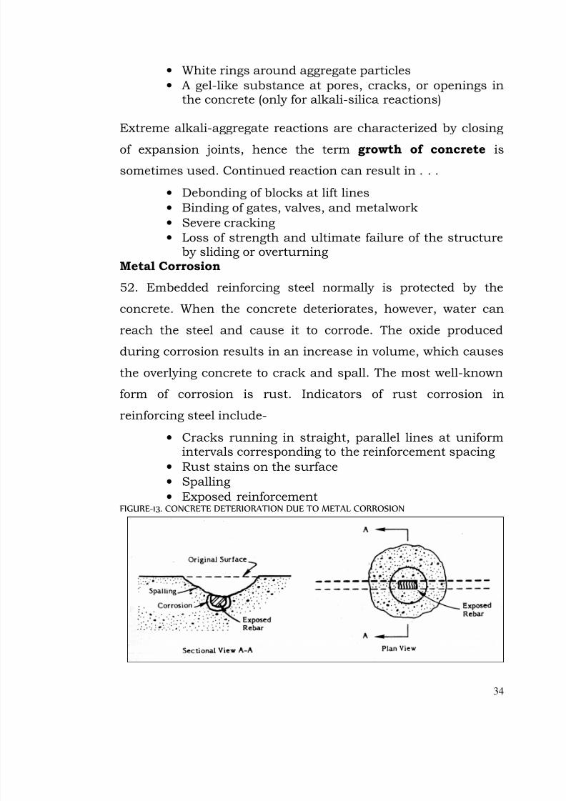
Metal Corrosion
52. Embedded reinforcing steel normally is protected by the
concrete. When the concrete deteriorates, however, water can
reach the steel and cause it to corrode. The oxide produced
during corrosion results in an increase in volume, which causes
the overlying concrete to crack and spall. The most well-known
form of corrosion is rust. Indicators of rust corrosion in
reinforcing steel include-• Cracks running in straight, parallel lines at uniform
intervals corresponding to the reinforcement spacing
• Rust stains on the surface
• Spalling
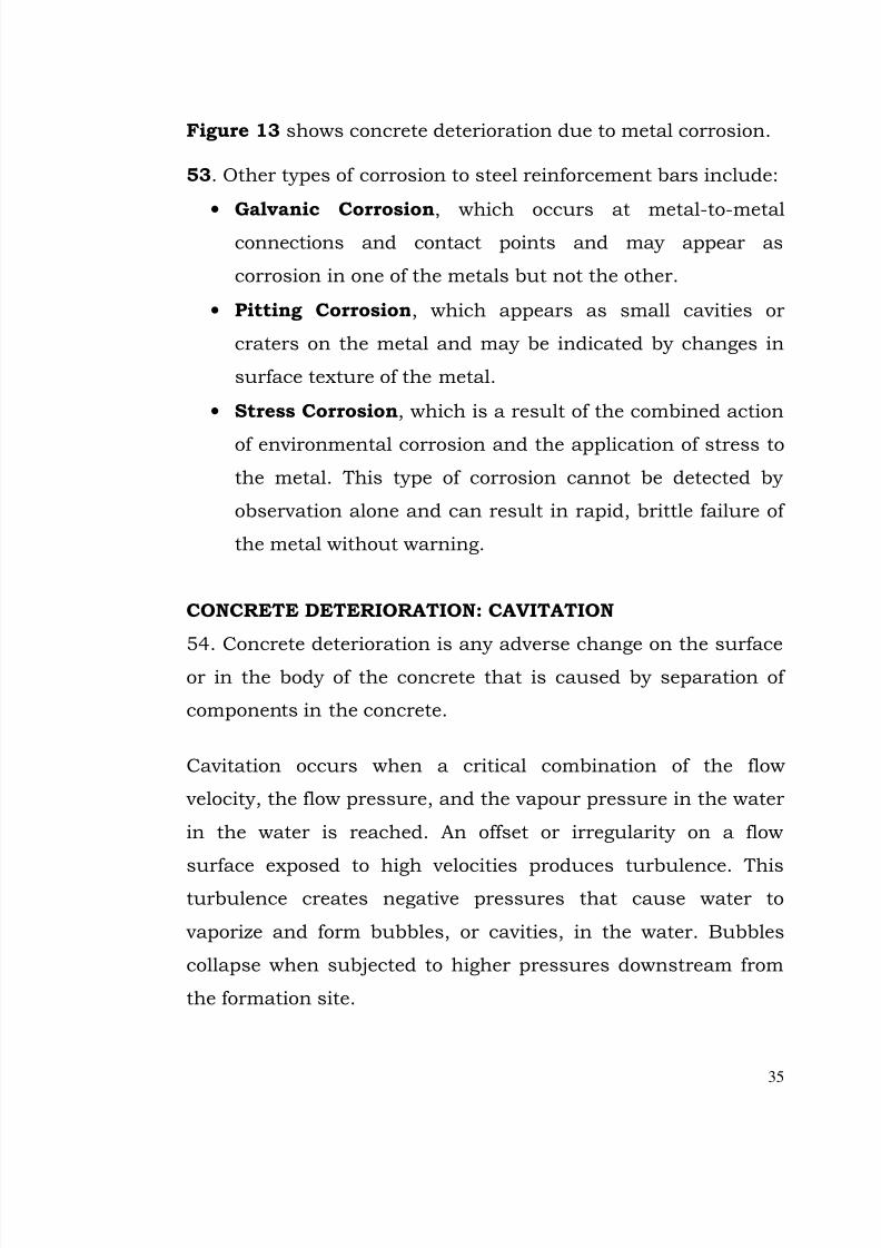
• Exposed reinforcementFIGURE-13. CONCRETE DETERIORATION DUE TO METAL CORROSION
7/28/2019 Manual for Inspection of Structures
http://slidepdf.com/reader/full/manual-for-inspection-of-structures 37/156
35
Figure 13 shows concrete deterioration due to metal corrosion.
53. Other types of corrosion to steel reinforcement bars include:
•
Galvanic Corrosion, which occurs at metal-to-metalconnections and contact points and may appear as
corrosion in one of the metals but not the other.
• Pitting Corrosion, which appears as small cavities or
craters on the metal and may be indicated by changes in
surface texture of the metal.
• Stress Corrosion, which is a result of the combined action
of environmental corrosion and the application of stress to
the metal. This type of corrosion cannot be detected by
observation alone and can result in rapid, brittle failure of
the metal without warning.
CONCRETE DETERIORATION: CAVITATION
54. Concrete deterioration is any adverse change on the surface
or in the body of the concrete that is caused by separation of
components in the concrete.
Cavitation occurs when a critical combination of the flow
velocity, the flow pressure, and the vapour pressure in the water
in the water is reached. An offset or irregularity on a flow
surface exposed to high velocities produces turbulence. Thisturbulence creates negative pressures that cause water to
vaporize and form bubbles, or cavities, in the water. Bubbles
collapse when subjected to higher pressures downstream from
the formation site.
7/28/2019 Manual for Inspection of Structures
http://slidepdf.com/reader/full/manual-for-inspection-of-structures 38/156
36
Bubble collapse dynamics then create shock waves that can
damage the flow surface. Popping and cracking noises
(Crepitation) accompany the collapse of the cavities. The impact
of the shock waves can produce pressure up to 100,000 pounds
per square inch. Repetition of these high-energy blows
eventually forms the pits or holes known as cavitation damage.
55. Common sites for cavitation are:
• Downstream of gates and valves
• In steep spillway chutes, tunnels or conduits
Cavitation may occur on the floor of a chute, or on the walls or
sides of a structure.
Cavitation damage resembles erosion damage, but cavitation is
potentially a much more serious problem, once the process
begins, deterioration can occur quickly. A tiny offset or
carbonate deposit may induce cavitation, leading to serious
damage or failure of the concrete in a structure during heavy
flows.
56. A pitted surface and/or rough holes with aggregate plucked
out suggest cavitation damage. Damage upstream and
progresses downstream in a “leapfrog” pattern: each cavitation
site triggers the deterioration of a new site downstream.
57. If cavitation is detected, try to determine what event caused
the damage and to evaluate the potential for further damage.
Consider the frequency of operation. Examine air vents to flow
passages visually or by pouring water into them to ensure that
they are not obstructed.

7/28/2019 Manual for Inspection of Structures
http://slidepdf.com/reader/full/manual-for-inspection-of-structures 39/156
37
58. Cavitation effects can sometimes be mitigated by repairing
the area stronger material such as steel polymer concrete.
Installing aeration slots in tunnels/ conduits eliminates negative
pressures by providing additional air to the affected areas.
Concrete Deterioration: Erosion:
59. Erosion in concrete usually begins with wearing away of the
matrix material around the aggregate, and appears as relatively
uniform damage over a large surface. In a spillway, fall or
escape, erosion is usually due to the movement of abrasive
materials being carried by the flowing water. Aprons and stillingbasins (also known as hydraulic jump basins or simply jump
basins) are especially susceptible. Erosion often occurs after
initially cavitation damage, and serves to increase and extend
the damage.
60.Points of abrupt change in the flow channel or corners
subjected to abrasive action are likely to show pronounced
effects. Examples are:
Bends leading from tunnels,Conduits, and chutes.
Energy dissipators in stilling basins.
61. Ballmilling is a specific form of concrete erosion. Repeated
rotation of debris (usually rocks) by discharging water grinds the
surface, usually in a circular pattern. Stilling/hydraulic jump
basins are prone to ball milling damage.
If the flows continue for long time periods and if abrasive
material is carried at relatively high velocities, extensive erosion
damage to concrete structures results. Erosion in a
7/28/2019 Manual for Inspection of Structures
http://slidepdf.com/reader/full/manual-for-inspection-of-structures 40/156
38
stilling/hydraulic jump basin floor can excavate enough
material to make the structure unstable.
Leaking Joints
62. Joints may leak because of damage to waterstops or other
joints problems.
Innadequate Or Damaged Waterstops:
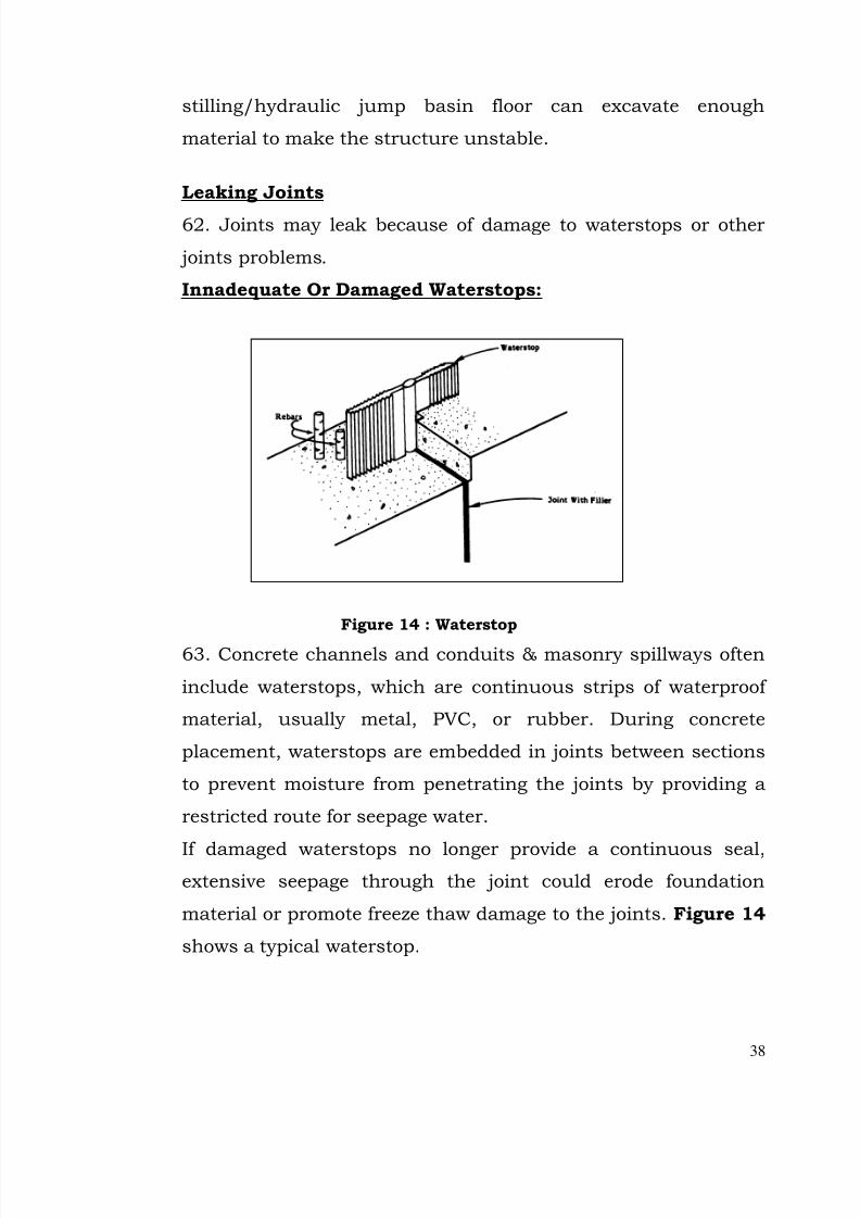
Figure 14 : Waterstop
63. Concrete channels and conduits & masonry spillways often
include waterstops, which are continuous strips of waterproof
material, usually metal, PVC, or rubber. During concrete
placement, waterstops are embedded in joints between sections
to prevent moisture from penetrating the joints by providing a
restricted route for seepage water.
If damaged waterstops no longer provide a continuous seal,extensive seepage through the joint could erode foundation
material or promote freeze thaw damage to the joints. Figure 14
shows a typical waterstop.
7/28/2019 Manual for Inspection of Structures
http://slidepdf.com/reader/full/manual-for-inspection-of-structures 41/156
39
Other Joint Problem:
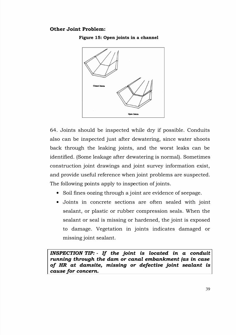
Figure 15: Open joints in a channel
64. Joints should be inspected while dry if possible. Conduits
also can be inspected just after dewatering, since water shoots
back through the leaking joints, and the worst leaks can be
identified. (Some leakage after dewatering is normal). Sometimes
construction joint drawings and joint survey information exist,
and provide useful reference when joint problems are suspected. The following points apply to inspection of joints.
• Soil fines oozing through a joint are evidence of seepage.
• Joints in concrete sections are often sealed with joint
sealant, or plastic or rubber compression seals. When the
sealant or seal is missing or hardened, the joint is exposed
to damage. Vegetation in joints indicates damaged or
missing joint sealant.
INSPECTION TIP: - If the joint is located in a conduit running through the dam or canal embankment (as in case of HR at damsite, missing or defective joint sealant is cause for concern.

7/28/2019 Manual for Inspection of Structures
http://slidepdf.com/reader/full/manual-for-inspection-of-structures 42/156
40
Surface Mapping
65. Surface mapping involves documenting concrete defects in a
systematic manner. All types of deterioration should beincluded. Surface mapping can be accomplished using detailed
drawings, photographs, or videotape. When photographs are
used, a ruler or familiar object should be included to indicate
scale. A grid is sometimes used to overlay a section of a drawing
so the location of cracks and other defects can be shown easily.
Figure 16 shows an example of surface mapping of concrete
deterioration.
CONCRETE DETERIORATION : INSPECTION ACTIONS
66. Common sense and your organization’s procedures must
guide you in responding to concrete deterioration. If you observe
cracking or other deterioration of concrete, you should ….
• Use the SMPL rule to document the deteriorationSketch, measure, photograph and locate indicatingdirection (longitudinal, transverse, horizontal, vertical
FIGURE-16. SURFACE MAPPING
7/28/2019 Manual for Inspection of Structures
http://slidepdf.com/reader/full/manual-for-inspection-of-structures 43/156
41
or diagonal), size, length, width, depth of deterioration.
.
• If surface maps exist, or if deterioration has beendocumented before, compare your observations with
recorded date and document your findings.
• Be alert to other types of deterioration in the concretethat may be related to an overall problem.
• Use a hammer or “bonker” to sound the concretesurface for drummy concrete.
INSPECTION TIP : Immediately notify Executive Engineerof any deterioration that is extensive, has changedsignificantly since the previous inspection or appears toaffect the integrity of the structure.
Carry out IMMEDIATE repairs if deterioration in concretereaches embedded reinforcement steel.
7/28/2019 Manual for Inspection of Structures
http://slidepdf.com/reader/full/manual-for-inspection-of-structures 44/156
42
4. METAL PROBLEMS COMMON IN STRUCTURES
Corrosion (Rust, Galvanic Action)
67. Corrosion is progressive deterioration resulting from
exposure to moisture acid and other corrosive agents, or
electrolysis, and usually is marked by scaling or flaking, pitting,
and color changes. Loss of paint or other protective coatings can
leave a metal surface subject to corrosion,
ESPECIALLY IF THE SURFACE is cycled between wet and dry.
Unchecked corrosion eventually leads to failure of a metal
structure.
Fatigue:
68.Fatigue is loss of metal strength from repetitive loading such
as being bent back and forth. Protrusions on metal components
or components with moving parts are most likely to suffer
fatigue. Distortions or cracked point may indicate sites where a
metal structure suffers from fatigue. The process continues untilthe affected area cracks and/or breaks.
Erosion :
69. Flow surface and areas around rivets and splice plates may
be scoured by abrasive debris.
Tearing and Rupture :
70. Tearing and rupture may result from impact, such as a log
slamming into a steel lining. On structures, metal components
are most likely to tear and rupture during storms or other
occasions when flows are heavy. Tears and ruptures can cause a

7/28/2019 Manual for Inspection of Structures
http://slidepdf.com/reader/full/manual-for-inspection-of-structures 45/156
43
metal structure to fail completely, or expose the structure to
corrosion, cavitation, fatigue or other damage.
Cavitation:
71. Cavitation of metal surfaces, such as metal conduits, can
occur when high flow velocities exist on a flow surface with
offsets and irregularities. The bubble collapse dynamics of
cavitation cause pitting of the surface which results in
progressive deterioration to the point of failure. As in concrete,
the site of initial cavitation damage triggers the formation of
another site downstream, so the process develops in a leapfrogpattern. Areas just downstream of gates and valves are
susceptible.
Cracking:
72. Cracking is usually induced by vibrations.
Deformation:
73. Stress may deform metal shapes. (“Egg-shaped” pipe is an
example.)
7/28/2019 Manual for Inspection of Structures
http://slidepdf.com/reader/full/manual-for-inspection-of-structures 46/156
44
Chapter 2
OBSTRUCTIONS
1. An obstruction is an unauthorized or unplanned addition to a
structure that reduces flow capacity.
Significance of Obstructions:
2. An obstructed spillway,escape or outlet works cannot perform
its function properly. During a flood, if reduced flow capacity
prevents the spillway or escapes from diverting enough water
from the reservoir/canal or the outlet works from lowering thewater level in reservoir/canal, the dam/canal embankment may
be overtopped, and put in danger of failure.
3. Causes of Obstructions:
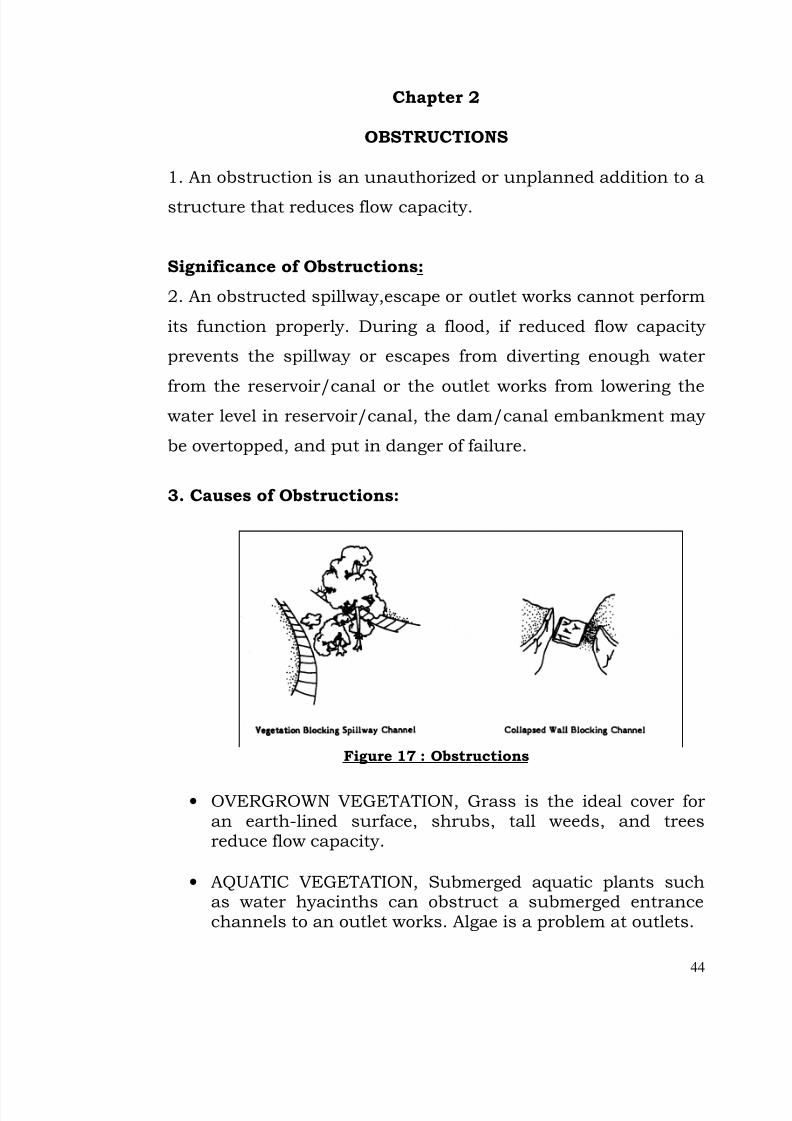
Figure 17 : Obstructions
• OVERGROWN VEGETATION, Grass is the ideal cover foran earth-lined surface, shrubs, tall weeds, and treesreduce flow capacity.
• AQUATIC VEGETATION, Submerged aquatic plants suchas water hyacinths can obstruct a submerged entrancechannels to an outlet works. Algae is a problem at outlets.
7/28/2019 Manual for Inspection of Structures
http://slidepdf.com/reader/full/manual-for-inspection-of-structures 47/156
45
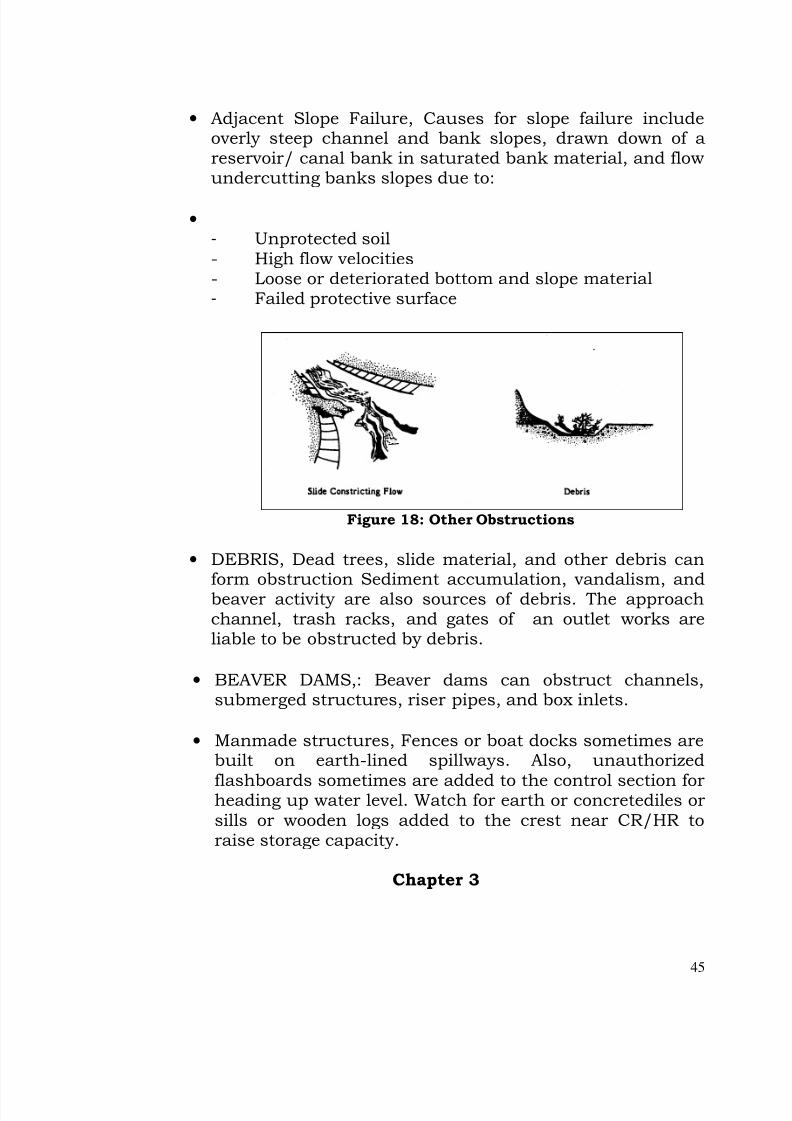
• Adjacent Slope Failure, Causes for slope failure includeoverly steep channel and bank slopes, drawn down of areservoir/ canal bank in saturated bank material, and flowundercutting banks slopes due to:
• - Unprotected soil- High flow velocities- Loose or deteriorated bottom and slope material- Failed protective surface
Figure 18: Other Obstructions
• DEBRIS, Dead trees, slide material, and other debris canform obstruction Sediment accumulation, vandalism, andbeaver activity are also sources of debris. The approachchannel, trash racks, and gates of an outlet works areliable to be obstructed by debris.
• BEAVER DAMS,: Beaver dams can obstruct channels,submerged structures, riser pipes, and box inlets.
• Manmade structures, Fences or boat docks sometimes arebuilt on earth-lined spillways. Also, unauthorized
flashboards sometimes are added to the control section forheading up water level. Watch for earth or concretediles orsills or wooden logs added to the crest near CR/HR toraise storage capacity.
Chapter 3
7/28/2019 Manual for Inspection of Structures
http://slidepdf.com/reader/full/manual-for-inspection-of-structures 48/156
46
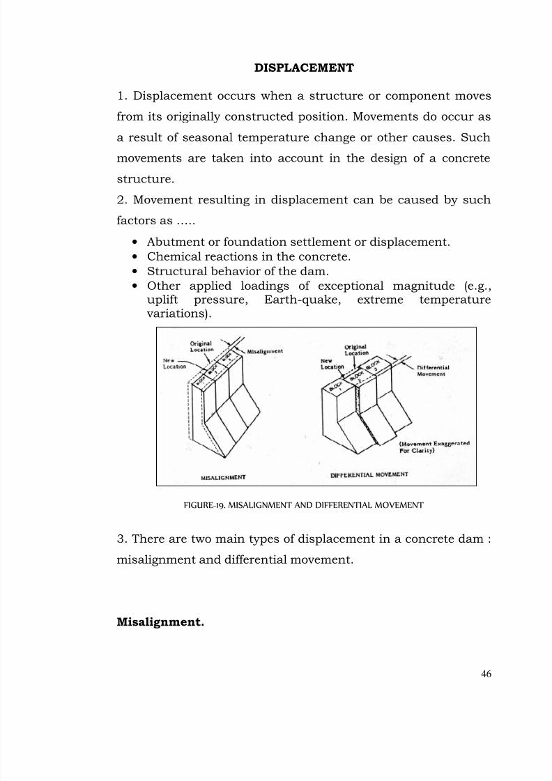
DISPLACEMENT
1. Displacement occurs when a structure or component moves
from its originally constructed position. Movements do occur as
a result of seasonal temperature change or other causes. Such
movements are taken into account in the design of a concrete
structure.
2. Movement resulting in displacement can be caused by such
factors as …..
• Abutment or foundation settlement or displacement.
• Chemical reactions in the concrete.
• Structural behavior of the dam.• Other applied loadings of exceptional magnitude (e.g.,
uplift pressure, Earth-quake, extreme temperaturevariations).
FIGURE-19. MISALIGNMENT AND DIFFERENTIAL MOVEMENT
3. There are two main types of displacement in a concrete dam :
misalignment and differential movement.
Misalignment.
7/28/2019 Manual for Inspection of Structures
http://slidepdf.com/reader/full/manual-for-inspection-of-structures 49/156
47
4. Misalignment is any variation from the original structural
configuration.
Differential Movement.
5. Differential movement occurs when one part of the structuremoves with respect to adjacent parts of the structure. Figure 19
presents examples of misalignment and differential movement.
Detecting Displacement
6.You are most likely to detect displacement by using sighting
techniques at the top of the structural member. Differential
movement most often appears as deflection at joints between
adjacent blocks. Other indicators of displacement include……
• Volume change in the concrete.
• Closing or opening of joints.
• Loss of joint filler.
• Cracking.
• Debonding of lifts.
• Tilting, shearing, or shifting of hardware or machinery.
• Binding of gates.
DISPLACEMENT : INSPECTION ACTIONS.
7. Movement in and of itself is not bad. Small movements are of
little concern and usually are considered in the design of the
structure. Movement becomes significant when it has an
adverse impact on the entire structure or on one or more of its
parts.
INSPECTION TIP : Significant changes – either in
magnitude or in directions should be evaluated immediately
consult Design Circle.
When you prepare for an inspection, you should-
7/28/2019 Manual for Inspection of Structures
http://slidepdf.com/reader/full/manual-for-inspection-of-structures 50/156
48
• Study data from previous inspection reports or derivedfrom surveys, if available.
• Focus on areas of the structure where evidence of movement has been noted.
When you inspect for displacement, you should …
• Use sighting techniques along the top of thestructural member to look for misalignment anddifferential movement.
• Inspect joints, hardware, and equipment for evidenceof differential movement.
• Watch for structural cracking.
• Be alert for any changes in or new occurrences of displacement.
• For all displacement observed, record :o Location.o Extent.o Direction of displacement.o Any other evidence of movement.o Observations on date, time, and temperature.
INSPECTION TIP : Make sure to record the relative water
levels in the canal both upstream and downstream of the
structure.
Graphics or computer plots can be developed that allow you to
distinguish between seasonal movement cycles and potential
problems.
SMALL SCALE MISALIGNMENT:
Defining Small-Scale Misalignment
8. One type of small-scale misalignment, called differential
movement, is localized movement of one section of a lining, wall
ogee monolith, or other escape component relative to adjacent
sections, Causes of differential movement include:
7/28/2019 Manual for Inspection of Structures
http://slidepdf.com/reader/full/manual-for-inspection-of-structures 51/156
49
• Loss of foundation or backfill
• Expensive clay shale foundation
• Poor drainage resulting in pressure behind the structure
9. Small-Scale misalignment may also result from misplacement
during construction. Figure 20 shows an offset between
sections of a chute. Pressures (possibly from poor drainage)
have moved the sidewalls inward in the upper section of the
chute).
Significance of Small-Scale Misalignment:
10.Small-Scale misalignment is a significant problems because -
• Offsets on flow surfaces can cause erosion and, in some
cases, cavitation. Both can eventually cause the structure to
fail.
• Gaps between joints allow water to penetrate and undermine
foundation material, creating excessive uplift pressure,
and/or allowing earth or rock material to escape.
• Compression across joint surfaces can result in concrete
spalling metal deformation, or ruptured water stops
Large-Scale Misalignment:
Defining Large Scale Misalignment :
11. Large Scale Misalignment is the dislocation of entire
structures from their design locations.
Causes of Large-Scale Misalignment:

7/28/2019 Manual for Inspection of Structures
http://slidepdf.com/reader/full/manual-for-inspection-of-structures 52/156
50
12. One example of large-scale misalignment is a conduit that
sags below its design horizontal centerline. Deformations of
failures responsible for large-scale misalignment include:
• Over compacted backfill, excessive earth pressure, orhydrostatic pushing the structure out of position.
• Loss of backfill or foundation materials.
• Base spreading.
• Shear failure in foundation.
• Settlement of foundation.
• Seismic activity causing foundation collapse.
13. Large-Scale misalignment may cause a structure to fail.
Landmarks, boundaries, and sighting techniques can be used to
check for this problem.
Chapter 5
FOUNDATION AND BACKFILL PROBLEMS:
7/28/2019 Manual for Inspection of Structures
http://slidepdf.com/reader/full/manual-for-inspection-of-structures 53/156
7/28/2019 Manual for Inspection of Structures
http://slidepdf.com/reader/full/manual-for-inspection-of-structures 54/156
52
SEEPAGE
1. Seepage is the slow percolation of water through the
embankment and its foundation.
What are Leakage and Seepage?
2. Some use the terms leakage and seepage interchangeably. For
the purposes of this module:
• Leakage is the flow of water through joints, cracks, andopenings in hydraulic structures.
• Seepage is the flow of water through the abutments or
foundation of the dam.
Significance of Seepage
3. Both the velocity and quality of seepage must be controlled or
piping will occur. Piping is a term that describes internal erosion
that begins at the downstream side of the embankment and
continues at a progressive rate towards the reservoir until an
internal pipe or direct conduit to the reservoir/canal has been
formed. Rapid failure of the dam/ canal embankment results.
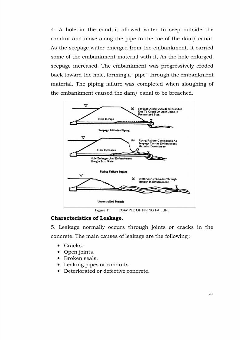
Figure 21 shows one way a piping failure can occur from
seepage through an outlet works.
7/28/2019 Manual for Inspection of Structures
http://slidepdf.com/reader/full/manual-for-inspection-of-structures 55/156
53
4. A hole in the conduit allowed water to seep outside the
conduit and move along the pipe to the toe of the dam/ canal.
As the seepage water emerged from the embankment, it carried
some of the embankment material with it, As the hole enlarged,seepage increased. The embankment was progressively eroded
back toward the hole, forming a “pipe” through the embankment
material. The piping failure was completed when sloughing of
the embankment caused the dam/ canal to be breached.
Figure 21 EXAMPLE OF PIPING FAILURE
Characteristics of Leakage.
5. Leakage normally occurs through joints or cracks in the
concrete. The main causes of leakage are the following :• Cracks.
• Open joints.
• Broken seals.
• Leaking pipes or conduits.
• Deteriorated or defective concrete.
7/28/2019 Manual for Inspection of Structures
http://slidepdf.com/reader/full/manual-for-inspection-of-structures 56/156
54
Evidence of leakage can vary from a moist or wet surface to a
concentrated flow of water. The most common indicators of
leakage in a concrete structure are:
•
Wetness on the downstream face of the structure.• Staining or buildup of sediments along joints and cracks.
• Water spurting or running out of joints or cracks on thedownstream face.
• Significant flows in the drainage system, and formeddrains, tail channels, river .
6. Leakage can result in an increased rate of deterioration of
concrete, leaching of concrete, loss of mass, and reduced
structural strength. Leakage can also cause excessive
hydrostatics pressure within the structure, leading to
overturning or sliding of blocks of the structure.
Characteristics of Seepage :
7. Seepage through the foundation and abutments can be
caused by the following conditions :
• Foundation deterioration.• Inadequate grout curtain.
• Joints or seems in the foundation or abutment material.
Evidence of seepage may include:-
• Wet areas on the abutments or foundation downstream of the structure.
• Lush vegetative growth in an area downstream of thestructure.
• Instability of the slopes (e.g., slumps and slides)downstream of the structure.
• Indications in instrument readings of undesirablehydrostatic pressure buildup.
8. The potential consequences of seepage include increased
uplift pressure and differential movement in the structure.
7/28/2019 Manual for Inspection of Structures
http://slidepdf.com/reader/full/manual-for-inspection-of-structures 57/156
55
Seepage also has the potential for solutioning soluble rock
materials or instability (sliding) of the abutment or foundation
and thus weakening the foundation, with potential failure as a
consequence in some cases. In very basic terms, excessiveleakage and seepage can lead to loss of usable water.
Monitoring Leakage and Seepage.
9. All concrete structures leak and seep. The amount of leakage
and seepage usually correlates with the water level in the
reservoir/ canal. Generally, as the water level in the reservoir/
canal rises, the seepage flow rate increases. Temperatures alsoaffect the amount of leakage during cold weather, concrete
contracts and joints or cracks open, increasing leakage.
10. As part of your inspection, you should monitor the rate and
trends of leakage and seepage. You will need to check previous
records of leakage and seepage for comparable water surface
elevations in the reservoir/canal so that you can compare your
findings. You are looking for:
• Significant new leakage or seepage.
• Major changes in leakage / seepage pattern or flow.
• Turbidity in seepage.
Turbidity.
11. Turbid water is cloudy, and is an indication that the
foundation material may be eroding.INSPECTION TIP : Turbidity is cause for concern.
Each time seepage is measured, clarity should be evaluated.
7/28/2019 Manual for Inspection of Structures
http://slidepdf.com/reader/full/manual-for-inspection-of-structures 58/156
56
Taking Measurements
12. Measure the amount of seepage and leakage and record in
the Operating Log (LogBook). If previous records are not
available for comparison, a program to collect flow data may need to be initiated. Don’t forget to include the water level in the
reservoi/ canal each time flows are measured. This will help
determine the cause of a change in the amount of flow. Clarity of
seepage i.e. whether clear or carrying sediment and any staining
or discoloration of concrete is to be noted in the LogBook.
There are various ways to take flow readings. The most common
are:
• The use of weirs (refer to the module on instrumentation).
• The use of a bucket and stopwatch.
Blocked Drains.
13. In monitoring leakage, increased flows are not the only
cause for concern. A noticeable decrease in seepage can indicate
that a drain is becoming blocked. Blocked drains can lead to
deterioration of the concrete/ masonry, increased
uplift/hydrostatic pressures, and potential stability problems.
LEAKAGE AND SEEPAGE : INSPECTION ACTIONS.
14. If you observe leakage or seepage, you should ….
Monitor the flow and record the following :
• Location and quantity or flow rate of all leakage andseepage at exit points.
• Occurrence of recent precipitation that may affect theappearance and quantity of seepage.
• Water level in the canal at the time of the observation.
• Check seepage for turbidity.
7/28/2019 Manual for Inspection of Structures
http://slidepdf.com/reader/full/manual-for-inspection-of-structures 59/156
57
• Document any suspected drain blockages. Arecommendation that the drains be cleaned may bewarranted.
INSPECTION TIP : Consult Executive Engineer if you
observe significant new leakage or seepage, major changes
in leakage / seepage pattern or flow, or turbidity in seepage.
7/28/2019 Manual for Inspection of Structures
http://slidepdf.com/reader/full/manual-for-inspection-of-structures 60/156
58
Chapter 7.
POOR DRAINAGE
Weepholes and Drains
1. Structures commonly have weepholes or other means of
drainage to prevent excess water pressure from developing
behind a structure. When no weepholes or drainage systems
exist, or when drains are plugged, excess water will accumulate.
This is a problem for the following reasons:
• A saturated foundation has lower bearing capacity.
• Uplift pressure from seepage water may cause damage to a
chute.
• Structure are designed for certain waterloads. If these
hydrostatic pressures are exceeded because of defective
drainage, then instability or distress can result.
2. Weepholes can become plugged by debris, infiltration of fines,
iron incrustation, and carbonate deposits. An inspection sight
includes probing weepholes to check for obstructions and
recording depth measurements on the crack maps.
Signs of poor drainage include:
• Ponding of water behind walls.
• Dampness on concrete surface, especially at cracks and
joints.
• Moistures seeping through cracks or joints.
• Tilted walls or heaved slabs
7/28/2019 Manual for Inspection of Structures
http://slidepdf.com/reader/full/manual-for-inspection-of-structures 61/156
59
Faulty Drainage: Inspection Actions.
3. You should-
• Observe the drain opening. Lock for deposits blocking the
opening.• Probe or sound drains to detect blockages.
• Check flow records for changes in flow rates that may indicate faulty drainage.
• Walk the gallery system and note the condition of gutters.Report gutter blockages and recommend prompt cleaning.
• Check pressure gauges.
7/28/2019 Manual for Inspection of Structures
http://slidepdf.com/reader/full/manual-for-inspection-of-structures 62/156
60
PART III
INSPECTION OF STRUCTURES

7/28/2019 Manual for Inspection of Structures
http://slidepdf.com/reader/full/manual-for-inspection-of-structures 63/156
61
Chapter 8
INSPECTION OF SPILLWAYS, WASTEWEIRS & ESCAPES
1. Spillways, Wsateweirs and Escapes are constructed to release
water in excess of the storage space in a dam/ canal. These are
important to the safety of dams/ canals, and maintenance to
allow proper functioning is essential. These usually are located
to discharge away from the embankment in order to preclude
erosion of the embankment when spilling. Regulated spillways/
escapes employ gates of various types to control the rate of flow
through the structure. Structural instability is evidenced by
deep cracks in slabs or walls, slab removal, foundation piping,
tilting of walls, and misalignment of walls. Obstructions
including debris, trash, trees, brush, and sediment diminish the
flow capacities of escape structures, stilling basins, and inflow
and outlet channels and may also produce undesirable erosion-
producing currents. Weep holes and drainage openings are
usually installed in the walls and floors of escape structures,
and these often become clogged with sediment and may be
occupied by animals or birds.
INSPECTION ACTION:
Inspect Annually the escape structure and channel for
instability, deterioration, obstructions, and erosion. Evidence of structural instability should be reportedimmediately, through Superintending Engineer in charge of the work to Design Circle who can assess significance andsuggest appropriate action to be taken.
7/28/2019 Manual for Inspection of Structures
http://slidepdf.com/reader/full/manual-for-inspection-of-structures 64/156
62
Structural deterioration that is progressive andendangering the structural integrity of the canal should berepaired.
Obstructions including debris, trash, dead and live trees,
and brush and sediment deposits should be removed.(Debris, trash, trees, and brush should be disposed of inaccordance with forest and environmental regulations)
2. General inspection required as outlined vide Part II shall
apply for all the components of spillways/wasteweirs/escapes.
Following gives further details for inspection to be carried out.
Checklist for inspection of spillways/wasteweirs/escapes is
provided at the end of this chapter.
Control Section:
3. The control section is a particularly critical portion of a
spillway/wasteweir/ escape, as it receives flow of water from the
reservoir/canal and passes on to river/ tail channel via energy
dissipation system. It may also be in the form of a weir with
crest (or sill level) raised above ground/canal bed level. The
spillway/wasteweir/escape must begin releasing water as
intended by design, whether the flow is triggered, when canal
water level reaches a predetermined level or through the
operation of gates or the removal/failure of stoplogs. The most
serious danger posed by the inability of the control section to
operate properly is that the water level in reservoir/canal may
rise and overtop the banks.
Problems typical to the escape control section include:
• Deterioration of surface materials:Check the following
points for deterioration in the control section:
7/28/2019 Manual for Inspection of Structures
http://slidepdf.com/reader/full/manual-for-inspection-of-structures 65/156
63
Look at surfaces in areas of concentrated and highvelocity flows, such as near gates, for erosion.
Check areas near large gates for cracking in concrete,and tearing, rupture, and fatigue in metal.
Examine the upstream edges of weirs for damage frombattering by debris. A boat may be used to inspect theupstream side of a weir immediately adjacent to thewater level.
INSPECTION TIP : High velocity flow over a concrete surface containing abnormalities can initiate cavitation damage. Check surfaces carefully for offsets, small holes and calcium carbonate deposits. The bearing surfaces
where gates rest and areas immediately downstream of gate slots, liner plates and air vents should be examined with special care.
• Obstructions:
4. Besides general types of obstructions already discussed,
check for the following obstructions to control sections:
Check for unauthorized equipment added to the controlsection.
• Backfill and Foundation Deficiencies:
5. Points to remember when inspecting the control section
for backfill and foundation deficiencies are:
Foundation in the control section often must bear thestress of heavy equipment. Check carefully fordisplacements that may indicate settling foundationshifts, or undermining. Check for voids under concretechannel walls and floors.
It is critical that gaps in joints do not expose foundationor backfill material where escape extends through the
7/28/2019 Manual for Inspection of Structures
http://slidepdf.com/reader/full/manual-for-inspection-of-structures 66/156
64
embankment section, and that water stops, sealantsand compressive joint fillers are intact and in goodcondition.
Check for clogged weep holes and foundation drains if present and watch for seepage and other signs of problems with the drainage system.
• Operating Bridge And Pier Problems:
6. Deficiencies in the operating bridge, piers, decks, or
other access structures on the spillway/wasteweir/escape
could make gates and other controls unworkable in an
emergency, and collapse of the supporting structure couldobstruct the spillway/wasteweir /escape.
7. Check for the following deficiencies.
On concrete bridges, check joints and water runoff points for exposed metal and corrosion of reinforcementsteel.
Check for peeling or missing paint
On steel flashing over joints inspect for break down of welds or mechanical connectors, couplings, and flanges.
Look for loose or insecurely anchored guardrails.
Check the condition of previously repaired areas.
Check & clear bridge drains every quarter
8. Check bridge support as follows.
On concrete bridge supports look for stress cracking.
Check the bearing supports at the abutments forcondition and evidence of movement.
Look for misalignment or damage at sliding joints.
7/28/2019 Manual for Inspection of Structures
http://slidepdf.com/reader/full/manual-for-inspection-of-structures 67/156
65
• Problems With Gates, Stoplogs:
9. When inspecting the control section of a
spillway/wasteweir/escape, your primary concern is to
ensure that the operation of gates and otherreservoir/canal evacuation equipment is not impaired by
adjacent and supporting structures.
10. When inspecting, stoplogs and structures adjacent to
and supporting gates check the following points.
Look for displacement of structural elements or
concrete deterioration that may be jamming ormisalignment gates. Have the equipment operated if possible, to detect jamming, or gates not seatedproperly on the crest. During operations, look fordeterioration of material on the underside of thegates. Note excessive leakage.
Watch for misalignment of gate stems and othersigns of strain from holding water or from debris or
over tightening.
Mechanical Equipment
11. All accessible parts of mechanical and associated
electrical equipment should be inspected visually every year
for damaged, deteriorated, corroded, cavitated, loose, worn,
or broken parts.
12. Mechanical and electrical equipment should be lubricated at
periodic intervals. The service and maintenance procedures
prescribed by the manufacturer should be followed for pumps,
motors, and other commercial components, where available.
7/28/2019 Manual for Inspection of Structures
http://slidepdf.com/reader/full/manual-for-inspection-of-structures 68/156
7/28/2019 Manual for Inspection of Structures
http://slidepdf.com/reader/full/manual-for-inspection-of-structures 69/156
67
Inspection of Gates and valves (annual).
(1) Visual inspection. –
When water conditions permit, inspect the downstreamsurfaces of the guard gate leaves and bodies, theupstream and downstream surfaces of regulating gateleaves and bodies, and outlet pipes.
Particular attention should be given to signs of cavitations damage to waterway surfaces downstreamfrom gate or valve leaves and flanged joints.
Inspect neoprene or rubber gate seals for deterioration,cracking, wear, foreign material deposits, and leakage.
Inspect valve and gates metal seats or seals for wear,scratches, foreign material deposits, and leakage.
Repairs should be made as necessary to keep theequipment in a safe and reliable operating condition.
(2) Exercising –
After lubrication, operate each valve and gate through afull cycle while under actual operating conditions, if
possible.
During operation, listen for unusual noises and checkfor binding or vibration.
Inspection of Hydraulic and manual operators and controlsystems for gates and valves (annual)
(1) Visual inspection -
Check hydraulic oil in the tank for proper fluid level(take into account displacement of the gate stem), water,and foreign materia1.
Check all pipe joints, cylinder flanges, packing, andhydraulic equipment for leaks.
7/28/2019 Manual for Inspection of Structures
http://slidepdf.com/reader/full/manual-for-inspection-of-structures 70/156
68
Check oil filters and strainers and change or clean if required.
Check hydraulic hoist piston stem for rusting andforeign deposits. Remove deposits and rough areas on
stems to prevent damage to packing or seals.
(2)Exercising
Operate hydraulic control and manual operator systemsand check for unusual noises or vibrations.
Check motors and hydraulic fluids for overheating, andcheck pressure switches, pressure gages, and limitswitches for proper operation according to operatinginstructions.
Clean manual operators of dirt and foreign material andlubricate as appropriate.
16. Physical security - The physical security should be
inspected for adequacy and repairs and improvements made, as
necessary, to avoid unauthorized operation and ensure the
safety of the equipment.
Inspection of Traveling crane, hoist, and tracks (annual)
(1) Visual inspection
Examine hoist, crane, and tracks for broken, bent,misaligned, worn, or loose parts and corrosion anddeterioration of protective coatings.
(2)Exercising
After lubrication, operate crane and hoist throughoutall functions and check for unusual noises, binding,and vibration during operation.
7/28/2019 Manual for Inspection of Structures
http://slidepdf.com/reader/full/manual-for-inspection-of-structures 71/156
69
ENERGY DISSIPATION SECTION:17. Use these general guidelines during your inspection of the
energy dissipation section of a spillway/wasteweir/escape or
HR/outlet works:
First and foremost, know how the structures are supposedto function.
Make close observations of the structures when in use.Note unusual water currents, eddies and swirls, especially return currents that would carry rock and debris into thestructure from downstream.
Look for “Sand boils” which result from the upward flow of
seepage under pressure and are characterized by a boilingaction of the surface seepage. A sand boil is oftenaccompanied by a cone of material around the boil whichdevelops from the deposition of foundation or embankmentmaterial varied by the seepage.
If possible, dewater the pool to inspect surfaces fordamage.
To inspect a large pool that cannot be dewatered, plan a
boat inspection and record soundings made A plumb bob/surveying equipment may be needed to determine thelocation of subsurface damage.
Underwater inspections by divers are recommended if problems are suspected. As with any underwaterinspection, a detailed inspection, a plan and a goodcommunication system are important considerations forlogging damaged areas.
Typical Problems With Energy Dissipation Section:
18. Damage can occur to all elements of an energy dissipation
section because these structures reduce the velocity and
dissipate the energy of a flow. If the energy dissipation structure
7/28/2019 Manual for Inspection of Structures
http://slidepdf.com/reader/full/manual-for-inspection-of-structures 72/156
7/28/2019 Manual for Inspection of Structures
http://slidepdf.com/reader/full/manual-for-inspection-of-structures 73/156
71
terminal structures are alwaysreinforced.
Inspect the submerged portions of plunge pools and stilling / hydraulic
jump basins while dewatered, if possible or use divers. (An underwatercamera or a remotely operated vehicle(ROV) might be used before divers.)
Riprap/Pitching Make sure that riprap/pitching is notdisplaced or lost and that foundationmaterial is protected. Look for pipingor voids beneath riprap/pitching.
Geotextiles Check riprap or gabion plunge poolsand downstream channels for exposedgeotextiles, which typically should notbe exposed to direct flow or sunlight.
20. Obstructions: Check energy dissipation sections for the
following obstruction:
Debris clogging baffles
Plunge pools, stilling / hydraulic jump basins, andareas down stream of flip buckets filling with debris(often rocks and other objects thrown by people)
Return currents bringing downstream materials intothe structure
Heavy vegetative growth (such as thick grasses) inplunge pools.
If you see material blocking flow note the type of material
dimensions and depth, and location relative to a side or an end.
A boat can be used to perform a hydrographic survey of a large
pool bottom to check for obstructions or damage.

7/28/2019 Manual for Inspection of Structures
http://slidepdf.com/reader/full/manual-for-inspection-of-structures 74/156
72
21. Damaged Or Missing Baffles: Baffles may be cracked
severely eroded loose or missing.
22. Misalignment Of Walls Or Baffles: The force of flows may
deflect the portion of terminal structures.
Check for vertically, and sight along the top of a sill foralignment deviation.
Check instrumentation data to measure deflections.
Offsets may occur as a result of misalignment, and cavitation
can developed downstream of such offsets.
23. Malfunctioning Drains: Check for clogged drains in the
energy dissipation area. Determine whether water flowing from
drains is clear or contains sediment or fine materials.
24. Backfill And Foundation Deficiencies: Check the following
points when inspecting the energy dissipation section for
backfill and foundation deficiencies:
Inspect plunge pools, hydraulic jump basins, and riprap-lined dissipators carefully for foundation and crack fillproblems. Look for settlement and cracks in backfill.Measure the size and distance of problem areas measuresettlement depth and probe for voids and erosion channels.
Watch especially for erosion of backfill behind the
downstream portion of a stilling / hydraulic jump basinscutoff walls and reinforcement should not be visible.
Settlement or improper elevation or length may change the jump location is stilling / hydraulic jump basins. Checkthat jump within the structure occurs at design locations(If the spillway/wasteweir/escape or HR/outlet works is
7/28/2019 Manual for Inspection of Structures
http://slidepdf.com/reader/full/manual-for-inspection-of-structures 75/156
73
not operating, water stains on the walls will indicate wherethe jump is actually occurring).
Look for misaligned dry walls, cracks in the basin, andcracked backfill for evidence that a jump basin is settling.
Check a riprap plunge pool for undermining by loss of underlying soil or lack of filter action.
If a plunge pool lining is sand or gravel, check for piping.TAIL CHANNEL
25. The tail channel discharges the flow from
spillway/wasteweir/escape into nearby river or nalla or even
drain. If it fails, excess discharge is likely to erode the lower
portion of the spillway/wasteweir/escape control section or
energy dissipation system, the groin and toe areas of
embankment or areas downstream of the spillway/wasteweir/
escape.
Tail channel is subject to the same general problems with
structure and material as Approach channel of the drainagesiphon, with additional concerns described below:
Erosion: Discharge entering the tail channel is generally at a higher velocity than flows through the approachchannel.The tail channel is very susceptible to erosion if not properly sized, aligned and protected from excessvelocity.Look for erosion gullies that may indicate impropercompaction, overtopping because of downstream
obstructions or poor vegetative cover.
Inadequate Length: The tail channel should extend farenough downstream to ensure that flows will notdamage the embankment groin and toe areas. If damageis occuring, it is extremely important to note thedeficiency.
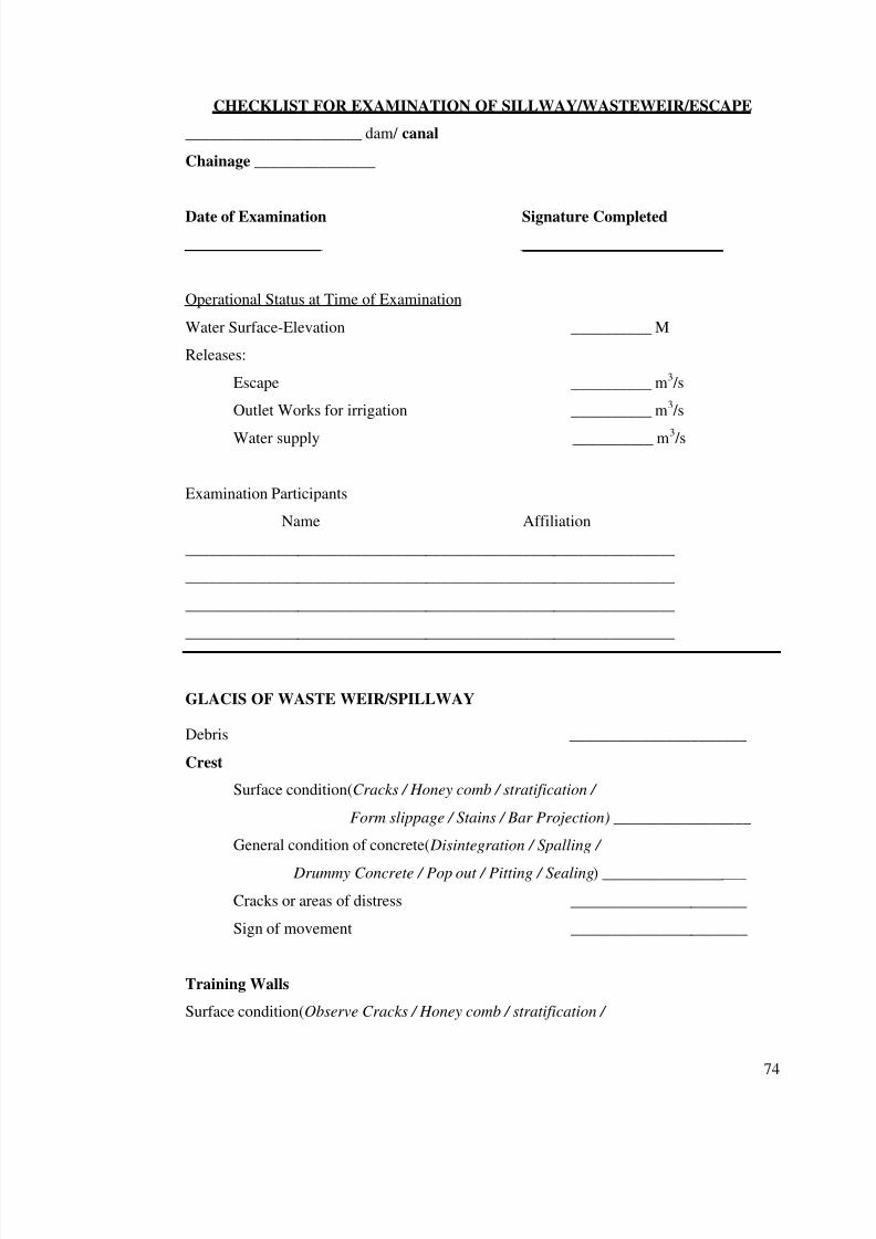
7/28/2019 Manual for Inspection of Structures
http://slidepdf.com/reader/full/manual-for-inspection-of-structures 76/156
74
CHECKLIST FOR EXAMINATION OF SILLWAY/WASTEWEIR/ESCAPE
______________________ dam/ canal
Chainage _______________
Date of Examination Signature Completed
_________________ _________________________
Operational Status at Time of Examination
Water Surface-Elevation __________ M
Releases:
Escape __________ m3 /s
Outlet Works for irrigation __________ m3 /s
Water supply __________ m3 /s
Examination Participants
Name Affiliation
_____________________________________________________________
_____________________________________________________________
_____________________________________________________________
_____________________________________________________________
GLACIS OF WASTE WEIR/SPILLWAY
Debris ______________________
Crest
Surface condition(Cracks / Honey comb / stratification /
Form slippage / Stains / Bar Projection) _________________
General condition of concrete( Disintegration / Spalling /
Drummy Concrete / Pop out / Pitting / Sealing) __________________
Cracks or areas of distress ______________________
Sign of movement ______________________
Training Walls
Surface condition(Observe Cracks / Honey comb / stratification /
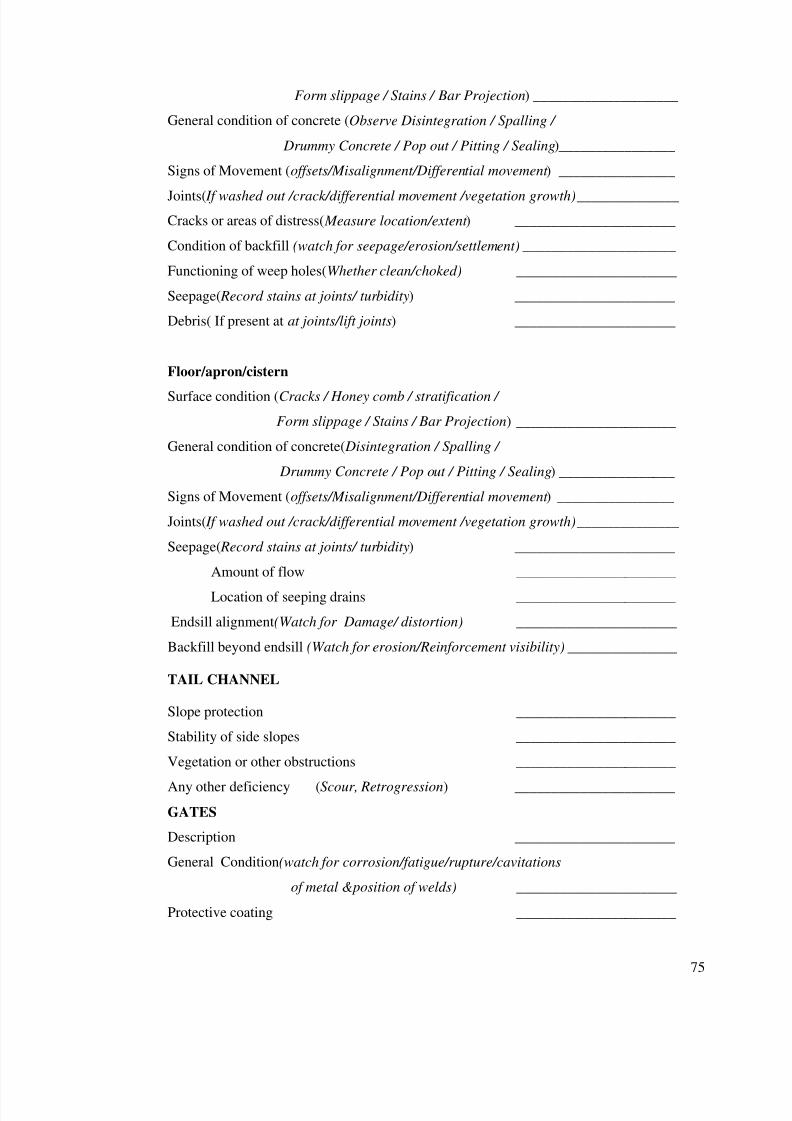
7/28/2019 Manual for Inspection of Structures
http://slidepdf.com/reader/full/manual-for-inspection-of-structures 77/156
75
Form slippage / Stains / Bar Projection) ____________________
General condition of concrete (Observe Disintegration / Spalling /
Drummy Concrete / Pop out / Pitting / Sealing) ________________
Signs of Movement (offsets/Misalignment/Differential movement ) ________________
Joints( If washed out /crack/differential movement /vegetation growth) ______________
Cracks or areas of distress( Measure location/extent ) ______________________
Condition of backfill (watch for seepage/erosion/settlement) _____________________
Functioning of weep holes(Whether clean/choked) ______________________
Seepage( Record stains at joints/ turbidity) ______________________
Debris( If present at at joints/lift joints) ______________________
Floor/apron/cistern
Surface condition (Cracks / Honey comb / stratification /
Form slippage / Stains / Bar Projection) ______________________
General condition of concrete( Disintegration / Spalling /
Drummy Concrete / Pop out / Pitting / Sealing) ________________
Signs of Movement (offsets/Misalignment/Differential movement ) ________________
Joints( If washed out /crack/differential movement /vegetation growth) ______________
Seepage( Record stains at joints/ turbidity) ______________________
Amount of flow ______________________
Location of seeping drains ______________________
Endsill alignment(Watch for Damage/ distortion) ______________________
Backfill beyond endsill (Watch for erosion/Reinforcement visibility) _______________
TAIL CHANNEL
Slope protection ______________________
Stability of side slopes ______________________
Vegetation or other obstructions ______________________
Any other deficiency (Scour, Retrogression) ______________________
GATES
Description ______________________
General Condition(watch for corrosion/fatigue/rupture/cavitations
of metal &position of welds) ______________________
Protective coating ______________________
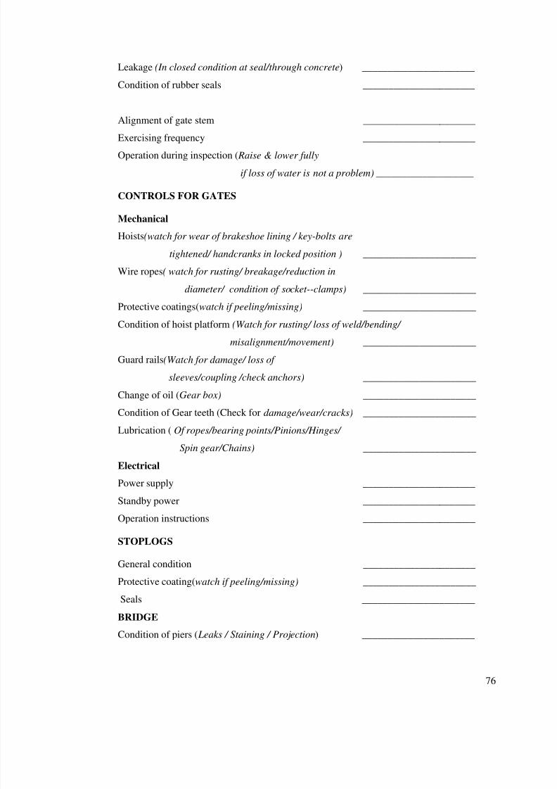
7/28/2019 Manual for Inspection of Structures
http://slidepdf.com/reader/full/manual-for-inspection-of-structures 78/156
76
Leakage (In closed condition at seal/through concrete) ______________________
Condition of rubber seals ______________________
Alignment of gate stem ______________________
Exercising frequency ______________________
Operation during inspection ( Raise & lower fully
if loss of water is not a problem) ___________________
CONTROLS FOR GATES
Mechanical
Hoists(watch for wear of brakeshoe lining / key-bolts are
tightened/ handcranks in locked position ) ______________________
Wire ropes( watch for rusting/ breakage/reduction indiameter/ condition of socket--clamps) ______________________
Protective coatings(watch if peeling/missing) ______________________
Condition of hoist platform (Watch for rusting/ loss of weld/bending/
misalignment/movement) ______________________
Guard rails(Watch for damage/ loss of
sleeves/coupling /check anchors) ______________________
Change of oil (Gear box) ______________________
Condition of Gear teeth (Check for damage/wear/cracks) ______________________
Lubrication ( Of ropes/bearing points/Pinions/Hinges/
Spin gear/Chains) ______________________
Electrical
Power supply ______________________
Standby power ______________________
Operation instructions ______________________
STOPLOGS
General condition ______________________
Protective coating(watch if peeling/missing) ______________________
Seals ______________________
BRIDGE
Condition of piers ( Leaks / Staining / Projection) ______________________
7/28/2019 Manual for Inspection of Structures
http://slidepdf.com/reader/full/manual-for-inspection-of-structures 79/156
7/28/2019 Manual for Inspection of Structures
http://slidepdf.com/reader/full/manual-for-inspection-of-structures 80/156
78
Chapter 9
INSPECTION OF CANAL SIPHON
1. Canal siphons consist of gated or ungated conduits (RCC
barrels or pipes ) with upstream and downstream transitions.
General inspection required as outlined vide Part II shall apply
for all the components of canal siphon. Following gives further
details for inspection to be carried out. Checklist for inspection
of canal siphon is provided at the end of this chapter.
Barrels / Pipes (Conduits)
2. A conduit is a pipe or box structure constructed by joining
sections.All outlets, HRs, canal siphons and drainage siphons
can generally be termed as conduits.
External Inspection Procedures for Conduits:
3. Evidence of potential conduit problems may BE found by
examining external features of the conduit (if it is exposed) or
the embankment.
If the material is reaching its life expectancy, it may bepossible to dig down to expose all sides of the conduit at apoint where the surrounding soil is still damp. Examinethe outside of the conduit for signs of deterioration. Thecondition of the outside of the conduit could besignificantly different from the interior. In some cases thesoil protects the exterior from oxygen-induced corrosion.
On the other hand local site conditions may haveaccelerated the deterioration of the exterior. Consider theoutside of the conduit to be just one indicator.
** Look for signs of infiltration of soil into the conduit:
7/28/2019 Manual for Inspection of Structures
http://slidepdf.com/reader/full/manual-for-inspection-of-structures 81/156
79
Sinkholes and piping cavities that exit the surface. Holestaken over by animals may not be easily recognized assinkholes or piping cavities.
Holes that appear to be in a line. These may be anindication that piping or settlement is occurring.
Fines in the discharged water.
** Look for seepage or indications that seepage is sometimespresent. (This is best done while the conduit is full).Indications of seepage are: Wet spots
Increased vegetation or the presence of plants that
thrive in wet ground.
** Watch for water flow when all intakes are closed. If any isobserved, double-check to see if intakes are leaking. If notdocument where water is entering the waterway, and examinethe water for fines.
** Look for piping related erosion around the conduit near thedownstream end. Check for seepage adjacent to the structure. The situation may be especially serious if the seepage is
carrying sediment.
** With exposed conduit, check the support for settlement of movement of the joints.
Internal Inspection Procedures for Conduits:
4. To attempting to inspect conduit interiors, you may
experience the following difficulties:
** Dewatering difficulties: You cannot inspect a conduitcomprehensively unless it has been dewatered. However,dewatering may be impractical or impossible for one ormore of the following reasons.
- The need to limit maximum drawdown
7/28/2019 Manual for Inspection of Structures
http://slidepdf.com/reader/full/manual-for-inspection-of-structures 82/156
80
- The need to maintain water flows.
- Structural inadequacy of the conduit to withstand
hydrostatic pressure in a dewatering condition.
To assess the probable condition of the conduit interior, itmay be necessary to rely on results of the exterior
inspection.
** Inaccessibility of conduit interior- The conduit may be
too dangerous for internal inspection by a person. One
possibility is to use remotely operated video equipment. If
that is not feasible, the inspection must be based on:
- The condition of the exposed portion of the conduit orthe embankment above it.
- The internal inspection of accessible portions of theconduit. (some details can be observed from thedownstream end of the conduit with the aid of astrong light and possibly a mirror).
INSPECTION TIP : One indication of settlement related problems that may be observed from the downstream end of a conduit is the pending of water in certain reaches of pipe.
5. A deficiency commonly encountered in the internal inspection
of conduit is cracking. Be aware of previously reported cracks
and note any new cracks, using a crack map or similar reporting
method. Figure --- shows one page of a crack map prepared by
an inspection team. Cracks should be documented as fully aspossible, with measurements and/or sketches drawn to scale
showing the length and position of each crack. The crack map in
figure includes measurements of the depth of weep holes, which
were probed during the inspection.
7/28/2019 Manual for Inspection of Structures
http://slidepdf.com/reader/full/manual-for-inspection-of-structures 83/156
81
6. To get some indication of whether cracks are continuous
through a concrete structure, use a geologists' pick or other
hammer to tap the concrete. More comprehensive studies of the
concrete using dye tests and sonic methods may be necessary if
there are indications that the crack extends any distance into
the structure.
7. When inspecting the interior of a conduit, document the
following:
** Cavitation damage downstream, from gates and at sharpbends, joints or other discontinuities.
** Corrosion of metal conduit or liner.
** Cracking: Use crack maps, Describe position, length andorientation (Transverse, longitudinal, or diagonal) Estimatethe depth of the crack.
** Damaged coating or lining materials. (Cracking or buckling
is a sign of structural stress Missing chunks can causecavitation).
** Debris impact.
** Deformation of the conduit shape.
** Efflorescent or gel on the concrete. (Indicates possiblechemical deterioration of the concrete).
** Erosion, especially in areas of high-velocity flow.
** Joint separation, compression, or deterioration. Mentionany unsound welds, rivets, or flanges.
** Leakage from the conduit, or seepage entering the conduit.
** Misalignment of sections of the conduit.
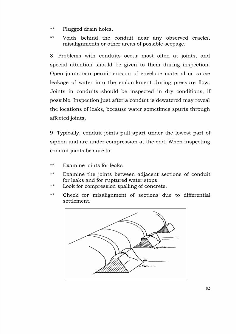
7/28/2019 Manual for Inspection of Structures
http://slidepdf.com/reader/full/manual-for-inspection-of-structures 84/156
82
** Plugged drain holes.
** Voids behind the conduit near any observed cracks,misalignments or other areas of possible seepage.
8. Problems with conduits occur most often at joints, andspecial attention should be given to them during inspection.
Open joints can permit erosion of envelope material or cause
leakage of water into the embankment during pressure flow.
Joints in conduits should be inspected in dry conditions, if
possible. Inspection just after a conduit is dewatered may reveal
the locations of leaks, because water sometimes spurts through
affected joints.
9. Typically, conduit joints pull apart under the lowest part of
siphon and are under compression at the end. When inspecting
conduit joints be sure to:
** Examine joints for leaks
** Examine the joints between adjacent sections of conduitfor leaks and for ruptured water stops.
** Look for compression spalling of concrete.
** Check for misalignment of sections due to differentialsettlement.

7/28/2019 Manual for Inspection of Structures
http://slidepdf.com/reader/full/manual-for-inspection-of-structures 85/156
83
Figure shows a conduit joint which has opened along the bottomdue to localized settlement along the conduit.
Operating Bridge And Pier Problems:
10. Deficiencies in the operating bridge, piers, decks, or other
access structures on the siphon could make gates and other
controls unworkable in an emergency, and collapse of the
supporting structure could obstruct the escape.
11.Check for the following deficiencies.
On concrete bridges, check joints and water runoff points for exposed metal and corrosion of reinforcementsteel.
Check for peeling or missing paint
On steel flashing over joints inspect for break down of welds or mechanical connectors, couplings, and flanges.
Look for loose or insecurely anchored guardrails.
Check the condition of previously repaired areas.
12. Check bridge support as follows.
On concrete bridge supports look for stress cracking.
Check the bearing supports at the abutments forcondition and evidence of movement.
Look for misalignment or damage at sliding joints.
Problems With Gates, Stoplogs:
13. When inspecting the control section of a siphon, your
primary concern is to ensure that the operation of gates and
other canal evacuation equipment is not impaired by adjacent
and supporting structures.

7/28/2019 Manual for Inspection of Structures
http://slidepdf.com/reader/full/manual-for-inspection-of-structures 86/156
84
When inspecting, stoplogs and structures adjacent to and
supporting gates check the following points.
Look for displacement of structural elements or
concrete deterioration that may be jamming ormisalignment gates. Have the equipment operated if possible, to detect jamming, or gates not seatedproperly on the crest. During operations, look fordeterioration of material on the underside of thegates. Note excessive leakage.
Watch for misalignment of gate stems and other
signs of strain from holding water or from debris or
over tightening.
Inspection of Gates and valves (annual).
(3) Visual inspection. –
When water conditions permit, inspect the downstreamsurfaces of the guard gate leaves and bodies, theupstream and downstream surfaces of regulating gateleaves and bodies, and outlet pipes.
Particular attention should be given to signs of cavitations damage to waterway surfaces downstreamfrom gate or valve leaves and flanged joints.
Inspect neoprene or rubber gate seals for deterioration,cracking, wear, foreign material deposits, and leakage.
Inspect valve and gates metal seats or seals for wear,scratches, foreign material deposits, and leakage.
Repairs should be made as necessary to keep theequipment in a safe and reliable operating condition.
(4) Exercising –
After lubrication, operate each valve and gate through afull cycle while under actual operating conditions, if possible.
7/28/2019 Manual for Inspection of Structures
http://slidepdf.com/reader/full/manual-for-inspection-of-structures 87/156
7/28/2019 Manual for Inspection of Structures
http://slidepdf.com/reader/full/manual-for-inspection-of-structures 88/156
86
Inspection of Traveling crane, hoist, and tracks (annual)
(2) Visual inspection
Examine hoist, crane, and tracks for broken, bent,misaligned, worn, or loose parts and corrosion anddeterioration of protective coatings.
(2)Exercising
After lubrication, operate crane and hoist throughoutall functions and check for unusual noises, binding,and vibration during operation.
Energy Dissipation Section:
15. Use these general guidelines during the your inspection of
the energy dissipation section of a canal siphon:
First and foremost, know how the structures are supposedto function.
Make close observations of the structures when in use.Note unusual water currents, eddies and swirls, especially
return currents that would carry rock and debris into thestructure from downstream.
Look for “Sand boils” which result from the upward flow of seepage under pressure and are characterized by a boilingaction of the surface seepage. A sand boil is oftenaccompanied by a cone of material around the boil whichdevelops from the deposition of foundation or embankmentmaterial varied by the seepage.
If possible, dewater the pool to inspect surfaces fordamage.
Underwater inspections by divers are recommended if problems are suspected. As with any underwaterinspection, a detailed inspection, a plan and a good
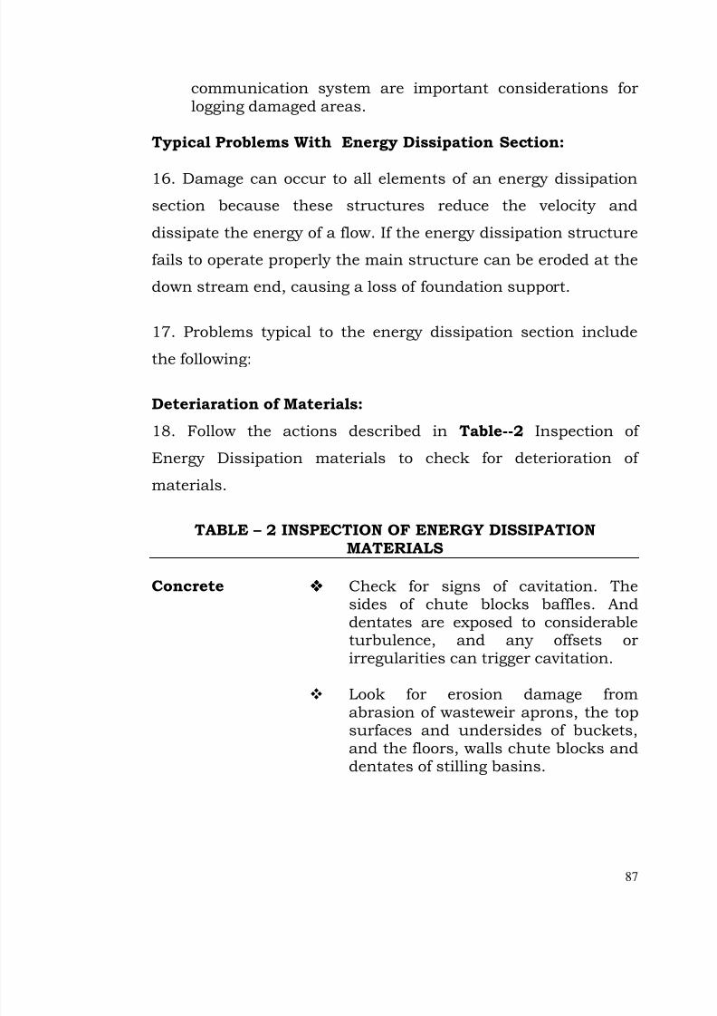
7/28/2019 Manual for Inspection of Structures
http://slidepdf.com/reader/full/manual-for-inspection-of-structures 89/156
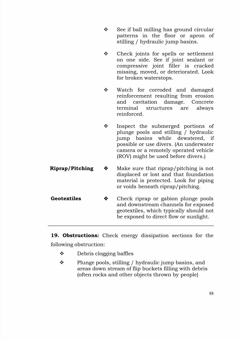
7/28/2019 Manual for Inspection of Structures
http://slidepdf.com/reader/full/manual-for-inspection-of-structures 90/156
88
See if ball milling has ground circularpatterns in the floor or apron of stilling / hydraulic jump basins.
Check joints for spells or settlement
on one side. See if joint sealant orcompressive joint filler is crackedmissing, moved, or deteriorated. Lookfor broken waterstops.
Watch for corroded and damagedreinforcement resulting from erosionand cavitation damage. Concreteterminal structures are alwaysreinforced.
Inspect the submerged portions of plunge pools and stilling / hydraulic jump basins while dewatered, if possible or use divers. (An underwatercamera or a remotely operated vehicle(ROV) might be used before divers.)
Riprap/Pitching Make sure that riprap/pitching is notdisplaced or lost and that foundation
material is protected. Look for pipingor voids beneath riprap/pitching.
Geotextiles Check riprap or gabion plunge poolsand downstream channels for exposedgeotextiles, which typically should notbe exposed to direct flow or sunlight.
19. Obstructions: Check energy dissipation sections for the
following obstruction:
Debris clogging baffles
Plunge pools, stilling / hydraulic jump basins, andareas down stream of flip buckets filling with debris(often rocks and other objects thrown by people)

7/28/2019 Manual for Inspection of Structures
http://slidepdf.com/reader/full/manual-for-inspection-of-structures 91/156
89
Return currents bringing downstream materials intothe structure
Heavy vegetative growth (such as thick grasses) in
plunge pools.
If you see material blocking flow note the type of material
dimensions and depth, and location relative to a side or an end.
A boat can be used to perform a hydrographic survey of a large
pool bottom to check for obstructions or damage.
20. Damaged Or Missing Baffles: Baffles may be cracked
severely eroded loose or missing.
21. Misalignment Of Walls Or Baffles: The force of flows may
deflect the portion of terminal structures.
Check for vertically, and sight along the top of a sill foralignment deviation.
Check instrumentation data to measure deflections.
Offsets may occur as a result of misalignment, and cavitation
can developed downstream of such offsets.
22. Malfunctioning Drains: Check for clogged drains in the
energy dissipation area. Determine whether water flowing from
drains is clear or contains sediment or fine materials.
23. Backfill And Foundation Deficiencies: Check the following
points when inspecting the energy dissipation section for
backfill and foundation deficiencies:
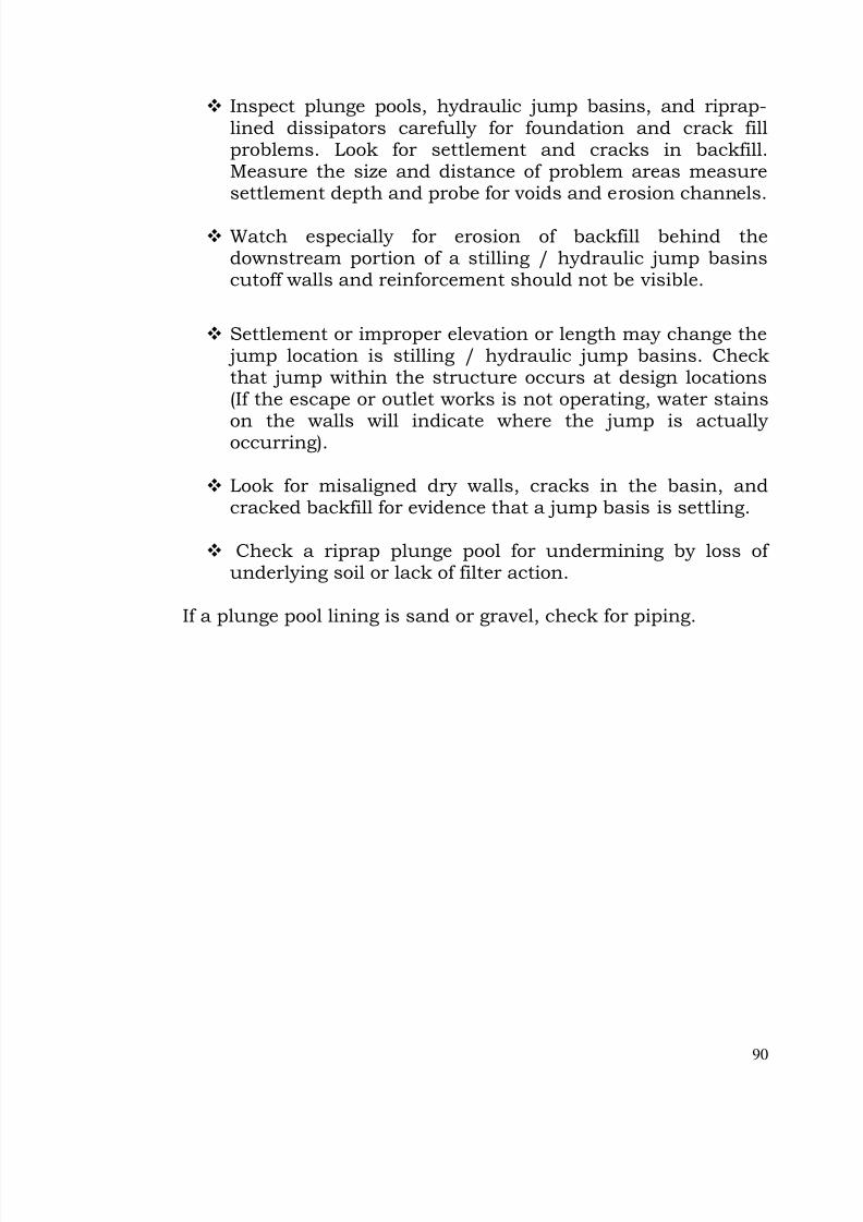
7/28/2019 Manual for Inspection of Structures
http://slidepdf.com/reader/full/manual-for-inspection-of-structures 92/156
90
Inspect plunge pools, hydraulic jump basins, and riprap-lined dissipators carefully for foundation and crack fillproblems. Look for settlement and cracks in backfill.Measure the size and distance of problem areas measuresettlement depth and probe for voids and erosion channels.
Watch especially for erosion of backfill behind thedownstream portion of a stilling / hydraulic jump basinscutoff walls and reinforcement should not be visible.
Settlement or improper elevation or length may change the jump location is stilling / hydraulic jump basins. Checkthat jump within the structure occurs at design locations(If the escape or outlet works is not operating, water stains
on the walls will indicate where the jump is actually occurring).
Look for misaligned dry walls, cracks in the basin, andcracked backfill for evidence that a jump basis is settling.
Check a riprap plunge pool for undermining by loss of underlying soil or lack of filter action.
If a plunge pool lining is sand or gravel, check for piping.
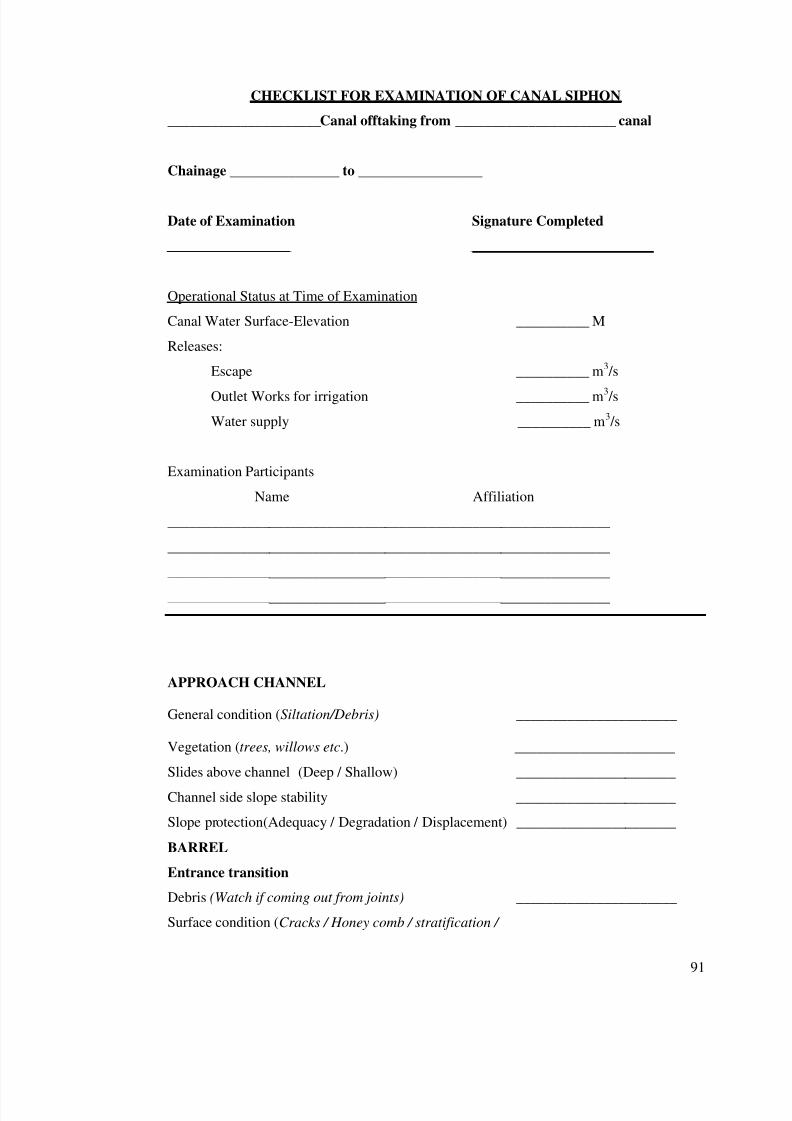
7/28/2019 Manual for Inspection of Structures
http://slidepdf.com/reader/full/manual-for-inspection-of-structures 93/156
91
CHECKLIST FOR EXAMINATION OF CANAL SIPHON
_____________________Canal offtaking from ______________________ canal
Chainage _______________ to _________________
Date of Examination Signature Completed
_________________ _________________________
Operational Status at Time of Examination
Canal Water Surface-Elevation __________ M
Releases:
Escape __________ m3 /s
Outlet Works for irrigation __________ m3 /s
Water supply __________ m3 /s
Examination Participants
Name Affiliation
_____________________________________________________________
_____________________________________________________________
_____________________________________________________________
_____________________________________________________________
APPROACH CHANNEL
General condition (Siltation/Debris) ______________________
Vegetation (trees, willows etc.) ______________________
Slides above channel (Deep / Shallow) ______________________
Channel side slope stability ______________________
Slope protection(Adequacy / Degradation / Displacement) ______________________
BARREL
Entrance transition
Debris (Watch if coming out from joints) ______________________
Surface condition (Cracks / Honey comb / stratification /
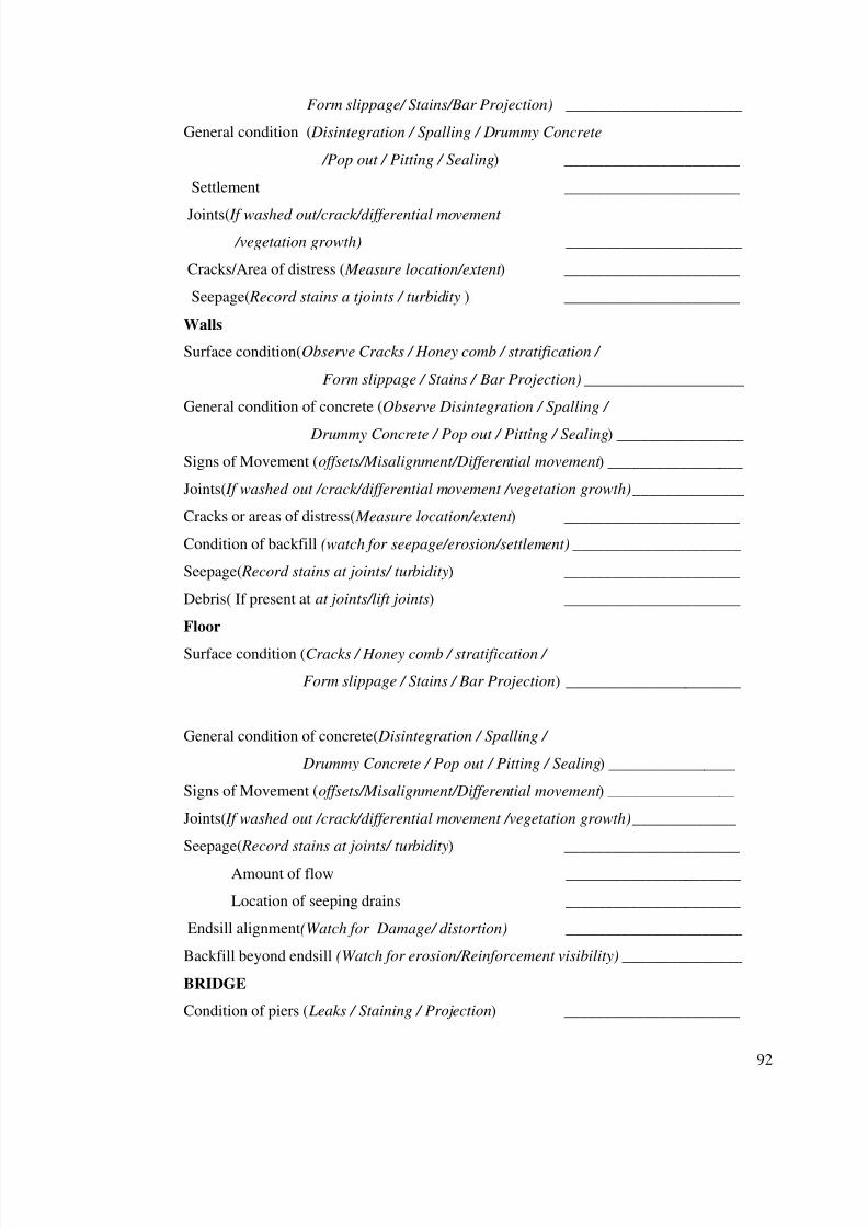
7/28/2019 Manual for Inspection of Structures
http://slidepdf.com/reader/full/manual-for-inspection-of-structures 94/156
92
Form slippage/ Stains/Bar Projection) ______________________
General condition ( Disintegration / Spalling / Drummy Concrete
/Pop out / Pitting / Sealing) ______________________
Settlement ______________________
Joints( If washed out/crack/differential movement
/vegetation growth) ______________________
Cracks/Area of distress ( Measure location/extent ) ______________________
Seepage( Record stains a tjoints / turbidity ) ______________________
Walls
Surface condition(Observe Cracks / Honey comb / stratification /
Form slippage / Stains / Bar Projection) ____________________
General condition of concrete (Observe Disintegration / Spalling /
Drummy Concrete / Pop out / Pitting / Sealing) ________________
Signs of Movement (offsets/Misalignment/Differential movement ) _________________
Joints( If washed out /crack/differential movement /vegetation growth) ______________
Cracks or areas of distress( Measure location/extent ) ______________________
Condition of backfill (watch for seepage/erosion/settlement) _____________________
Seepage( Record stains at joints/ turbidity) ______________________
Debris( If present at at joints/lift joints) ______________________
Floor
Surface condition (Cracks / Honey comb / stratification /
Form slippage / Stains / Bar Projection) ______________________
General condition of concrete( Disintegration / Spalling /
Drummy Concrete / Pop out / Pitting / Sealing) ________________
Signs of Movement (offsets/Misalignment/Differential movement ) ________________
Joints( If washed out /crack/differential movement /vegetation growth) _____________
Seepage( Record stains at joints/ turbidity) ______________________
Amount of flow ______________________
Location of seeping drains ______________________
Endsill alignment(Watch for Damage/ distortion) ______________________
Backfill beyond endsill (Watch for erosion/Reinforcement visibility) _______________
BRIDGE
Condition of piers ( Leaks / Staining / Projection) ______________________

7/28/2019 Manual for Inspection of Structures
http://slidepdf.com/reader/full/manual-for-inspection-of-structures 95/156
93
Surface of roadway slab ______________________
Water Spouts (whether choked) ______________________
Condition of parapet/Guard rails (watch for misalignment/
differential settlement) ______________________
Structural condition of slab and beams (watch for Deflection / Cracks) _____________________
Bridge bearings ______________________
Overall condition ______________________
TAIL CHANNEL
Slope protection ______________________
Stability of side slopes ______________________
Vegetation or other obstructions ______________________
Any other deficiency (Scour, Retrogression) ______________________
GATES
Description ______________________
General Condition(watch for corrosion/fatigue/rupture/cavitations
of metal &position of welds) ______________________
Protective coating ______________________
Leakage (In closed condition at seal/through concrete) ______________________
Condition of rubber seals ______________________
Alignment of gate stem ______________________
Exercising frequency ______________________
Operation during inspection ( Raise & lower fully
if loss of water is not a problem) ____________________
CONTROLS FOR GATES
Mechanical
Hoists(watch for wear of brakeshoe lining / key-bolts are
tightened/ handcranks in locked position ) ______________________
Wire ropes( watch for rusting/ breakage/reduction in
diameter/ condition of socket--clamps) ______________________
Protective coatings(watch if peeling/missing) ______________________
Condition of hoist platform (Watch for rusting/ loss of weld/bending/
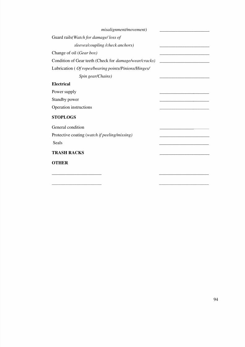
7/28/2019 Manual for Inspection of Structures
http://slidepdf.com/reader/full/manual-for-inspection-of-structures 96/156
94
misalignment/movement) ______________________
Guard rails(Watch for damage/ loss of
sleeves/coupling /check anchors) ______________________
Change of oil (Gear box) ______________________
Condition of Gear teeth (Check for damage/wear/cracks) ______________________
Lubrication ( Of ropes/bearing points/Pinions/Hinges/
Spin gear/Chains) ______________________
Electrical
Power supply ______________________
Standby power ______________________
Operation instructions ______________________
STOPLOGS
General condition ______________________
Protective coating (watch if peeling/missing) ______________________
Seals ______________________
TRASH RACKS ______________________
OTHER
______________________ ______________________
______________________ ______________________
7/28/2019 Manual for Inspection of Structures
http://slidepdf.com/reader/full/manual-for-inspection-of-structures 97/156
95
Chapter 10.
INSPECTION OF DRAINAGE SIPHON
1. Drainage siphons consist of conduits (RCC barrels or pipes )
with upstream and downstream transitions, approach and tail
channel. General inspection required as outlined vide Part II
shall apply for all the components of drainage siphon. Following
gives further details for inspection to be carried out. Checklist
for inspection of drainage siphon is provided at the end of this
chapter.
Approach Channel :
Typical Problems
2. Failure of the approach channel may block flow to the
drainage siphon entirely, greatly reduce the flow capacity, or
cause flow irregularities that imprnage upon or overtop channel
walls. As a result, the water surface in the drain may be raised
above safe levels, and the canal bank may even be overtopped.
3. Approach channels may be affected by:
• Deterioration of Materials. Slope and wall failure may
result when surface materials deteriorate. To inspect for
deterioration of surface materials perform the actions listed
in Table : 2 Inspecting approach channel Materials.
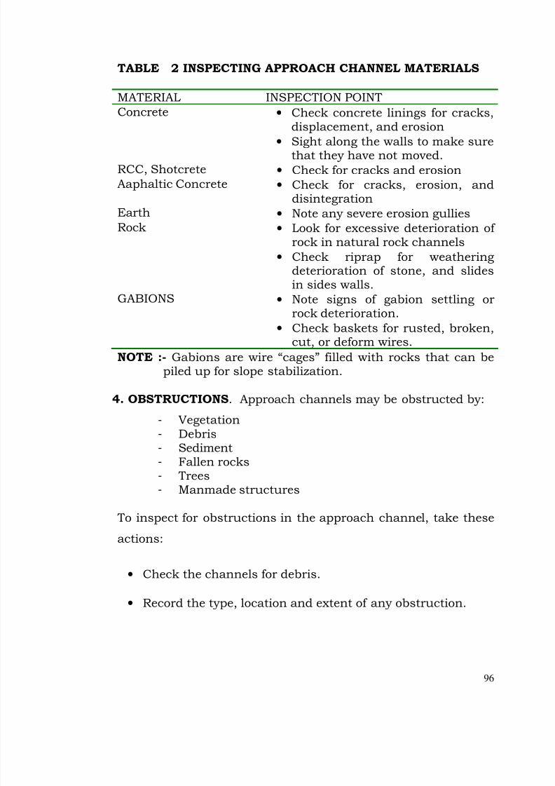
7/28/2019 Manual for Inspection of Structures
http://slidepdf.com/reader/full/manual-for-inspection-of-structures 98/156
96
TABLE 2 INSPECTING APPROACH CHANNEL MATERIALS
MATERIAL INSPECTION POINT
Concrete • Check concrete linings for cracks,displacement, and erosion
• Sight along the walls to make surethat they have not moved.
RCC, Shotcrete • Check for cracks and erosionAaphaltic Concrete • Check for cracks, erosion, and
disintegrationEarth • Note any severe erosion gulliesRock • Look for excessive deterioration of
rock in natural rock channels
• Check riprap for weathering
deterioration of stone, and slidesin sides walls.GABIONS • Note signs of gabion settling or
rock deterioration.
• Check baskets for rusted, broken,cut, or deform wires.
NOTE :- Gabions are wire “cages” filled with rocks that can bepiled up for slope stabilization.
4. OBSTRUCTIONS. Approach channels may be obstructed by:
- Vegetation- Debris- Sediment- Fallen rocks- Trees- Manmade structures
To inspect for obstructions in the approach channel, take these
actions:
• Check the channels for debris.
• Record the type, location and extent of any obstruction.
7/28/2019 Manual for Inspection of Structures
http://slidepdf.com/reader/full/manual-for-inspection-of-structures 99/156
97
5. Slope And Wall Failure. While inspecting the approach
channel for slope and wall failure, do the following:
• Examine the side slopes or walls for slides, movement,
cracked or wet spots. Check for foundation undermining by flow from springs.
• Look at the topography above the channel for signs of instability, such as sinkholes or slumps behind the walls. If you see soil loss with seepage, look for an exit points.
• Check for indications of poor drainage, such as seepage andclogged weepholes or drains.
6. Poor Floor Condition or Stability. Check these points when
examining the entrance channel floor.
• If the channel is unlined:o Look at the toe of the channel slope for wet areas.o Check for erosion sinkholes and lack of vegetation.
• Check foundation foe signs of undermining by clow from
springs.
• Look for signs of poor drainage, such as seepage andclogged weepholes or drains,
• Inspect for voids under a concrete floor, using a bunker ora hammer. (Another device that may be used is a “Chaindrag” which is a series of chains fastened to a bar.Concrete is sounded by dragging the chains over a surface. This device is used to test large areas).
7. Concrete Deteriaration From Wetting/Drying. Concrete
deteriorates from wetting and drying as the water level rises and
falls. The waterline of the approach channel needs to be checked
for cracking, scaling and crumbing of the concrete surface.
7/28/2019 Manual for Inspection of Structures
http://slidepdf.com/reader/full/manual-for-inspection-of-structures 100/156
98
8. Wave Erosion. Check side slopes or pitching for beaching
from wave erosion. The overly-steep channel slope above the
beach may fail.
9. Insufficient Capacity. If you see evidence of overtopping and
a flow restriction does nor appear to be contributing factor,
recommended that a hydrologic study be conducted to see
whether the approach channel can satisfy operational
requirements.
Tail Channel
10 The tail channel discharges the flow from the conduit(s) of
drainage siphon into nearby river or nalla or even drain. If it
fails, excess discharge is likely to erode the downstream portion
of the drainage siphon or energy dissipation system, the groin
and toe areas of canal emabankment or areas further
downstream of the drainage siphon.
Tail channel is subject to the same general problrms with
structure and material as Approach channel of the drainage
siphon, with additional concerns described below:
Erosion: Discharge entering the tail channel is generally at a higher velocity than flows through the approachchannel.The tail channel is very susceptible to erosion if not properly sized, aligned and protected from excessvelocity.
Look for erosion gullies that may indicate impropercompaction, overtopping because of downstreamobstructions or poor vegetative cover.
Inadequate Length: The tail channel should extend farenough downstream to ensure that flows will notdamage the embankment groin and toe areas. If damage
7/28/2019 Manual for Inspection of Structures
http://slidepdf.com/reader/full/manual-for-inspection-of-structures 101/156
99
is occuring, it is extremely important to note thedeficiency.
Barrels (Conduits)
11. A conduit is a pipe or box structure constructed by joining
sections.All outlets, HRs, canal siphons and drainage siphons
can generally be termed as conduits.
External Inspection Procedures for Conduits:
12. Evidence of potential conduit problems may be found by
examining external features of the conduit (if it is exposed) or
the embankment.
If the material is reaching its life expectancy, it may bepossible to dig down to expose all sides of the conduit at apoint where the surrounding soil is still damp. Examinethe outside of the conduit for signs of deterioration. Thecondition of the outside of the conduit could besignificantly different from the interior. In some cases thesoil protects the exterior from oxygen-induced corrosion.
On the other hand local site conditions may haveaccelerated the deterioration of the exterior. Consider theoutside of the conduit to be just one indicator.
** Look for signs of infiltration of soil into the conduit:
Depression of the embankment along the centerline of theconduit.
Sinkholes and piping cavities that exit the surface. Holestaken over by animals may not be easily recognized assinkholes or piping cavities.
Holes that appear to be in a line. These may be anindication that piping or settlement is occurring.
7/28/2019 Manual for Inspection of Structures
http://slidepdf.com/reader/full/manual-for-inspection-of-structures 102/156
100
Fines in the discharged water.
** Look for seepage or indications that seepage is sometimespresent. (This is best done while the conduit is full).
Indications of seepage are: Wet spots Increased vegetation or the presence of plants that
thrive in wet ground.
** Watch for water flow when there is no flow in the conduit. If any is observed, document from where water is entering thewaterway, and examine the water for fines.
** Look for piping related erosion around the conduit near the
downstream end. Check the embankment slope above theconduit outfall carefully for voids or erosion that may indicatepiping. Check for seepage adjacent to the structure. Thesituation may be especially serious if the seepage is carryingsediment.
** With exposed conduit, check the support for settlement of movement of the joints.
Internal Inspection Procedures for Conduits:
13. To attempting to inspect conduit interiors, you may
experience the following difficulties:
** Dewatering difficulties: You cannot inspect a conduitcomprehensively unless it has been dewatered. However,dewatering may be impractical or impossible due tostructural inadequacy of the conduit to withstandhydrostatic pressure in a dewatering condition.
To assess the probable condition of the conduit interior, it
may be necessary to rely on results of the exterior
inspection.
7/28/2019 Manual for Inspection of Structures
http://slidepdf.com/reader/full/manual-for-inspection-of-structures 103/156
101
** Inaccessibility of conduit interior- The conduit may be
too small or too dangerous for internal inspection by a
person. One possibility is to use remotely operated video
equipment. If that is not feasible, the inspection must bebased on:
- The condition of the exposed portion of the conduit orthe embankment above it.
- The internal inspection of accessible portions of theconduit. (some details can be observed from thedownstream end of the conduit with the aid of astrong light and possibly a mirror).
INSPECTION TIP : One indication of settlement related problems that may be be observed from the downstream end of a conduit is the ponding of water in certain reaches of pipe.
14. A deficiency commonly encountered in the internal
inspection of conduit is cracking. Be aware of previously
reported cracks and note any new cracks, using a crack map or
similar reporting method. Figure -6- shows one page of a crack
map prepared by an inspection team. Cracks should be
documented as fully as possible, with measurements and/or
sketches drawn to scale showing the length and position of each
crack. The crack map in figure includes measurements of the
depth of weep holes, which were probed during the inspection.
15. To get some indication of whether cracks are continuous
through a concrete structure, use a geologists' pick or other
hammer to tap the concrete. More comprehensive studies of the
concrete using dye tests and sonic methods may be necessary if
7/28/2019 Manual for Inspection of Structures
http://slidepdf.com/reader/full/manual-for-inspection-of-structures 104/156
102
there are indications that the crack extends any distance into
the structure.
16. When inspecting the interior of a conduit, document the
following:
** Cavitation damage downstream, at sharp bends, joints orother discontinuities.
** Corrosion of metal conduit or liner.
** Cracking: Use crack maps, Describe position, length andorientation (Transverse, longitudinal, or diagonal) Estimate
the depth of the crack.
** Damaged coating or lining materials. (Cracking or bucklingis a sign of structural stress Missing chunks can causecavitation).
** Debris impact.
** Deformation of the conduit shape.
** Efflorescent or gel on the concrete. (Indicates possible
chemical deterioration of the concrete).
** Erosion, especially in areas of high-velocity flow.
** Joint separation, compression, or deterioration. Mentionany unsound welds, rivets, or flanges.
** Leakage from the conduit, or seepage entering the conduit.
** Misalignment of sections of the conduit.
** Plugged drain holes.
** Voids behind the conduit near any observed cracks,
misalignments or other areas of possible seepage.
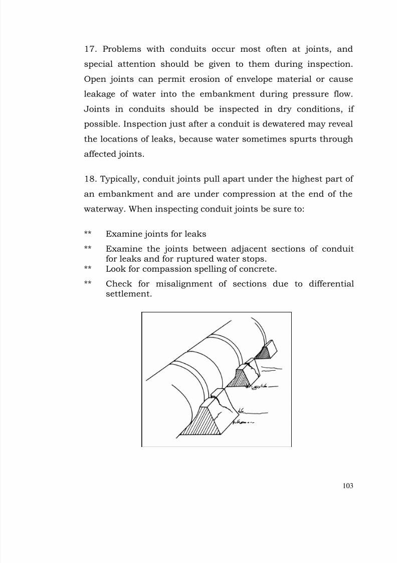
7/28/2019 Manual for Inspection of Structures
http://slidepdf.com/reader/full/manual-for-inspection-of-structures 105/156
103
17. Problems with conduits occur most often at joints, and
special attention should be given to them during inspection.
Open joints can permit erosion of envelope material or cause
leakage of water into the embankment during pressure flow. Joints in conduits should be inspected in dry conditions, if
possible. Inspection just after a conduit is dewatered may reveal
the locations of leaks, because water sometimes spurts through
affected joints.
18. Typically, conduit joints pull apart under the highest part of
an embankment and are under compression at the end of thewaterway. When inspecting conduit joints be sure to:
** Examine joints for leaks
** Examine the joints between adjacent sections of conduitfor leaks and for ruptured water stops.
** Look for compassion spelling of concrete.
** Check for misalignment of sections due to differential
settlement.

7/28/2019 Manual for Inspection of Structures
http://slidepdf.com/reader/full/manual-for-inspection-of-structures 106/156
7/28/2019 Manual for Inspection of Structures
http://slidepdf.com/reader/full/manual-for-inspection-of-structures 107/156
105
Typical Problems With Energy Dissipation Section:
20. Damage can occur to all elements of an energy dissipation
section because these structures reduce the velocity and
dissipate the energy of a flow. If the energy dissipation structure
fails to operate properly the main structure can be eroded at the
down stream end, causing a loss of foundation support.
21. Problems typical to the energy dissipation section include
the following:
Deteriaration of Materials:22. Follow the actions described in Table--4 Inspection of
Energy Dissipation materials to check for deterioration of
materials.
TABLE – 4 INSPECTION OF ENERGY DISSIPATIONMATERIALS
Concrete Check for signs of cavitation. Thesides of chute blocks baffles. Anddentates are exposed to considerableturbulence, and any offsets orirregularities can trigger cavitation.
Look for erosion damage fromabrasion of wasteweir aprons, the topsurfaces and undersides of buckets,and the floors, walls chute blocks and
dentates of stilling basins.
See if ball milling has ground circularpatterns in the floor or apron of stilling / hydraulic jump basins.

7/28/2019 Manual for Inspection of Structures
http://slidepdf.com/reader/full/manual-for-inspection-of-structures 108/156
7/28/2019 Manual for Inspection of Structures
http://slidepdf.com/reader/full/manual-for-inspection-of-structures 109/156
107
Heavy vegetative growth (such as thick grasses) inplunge pools.
If you see material blocking flow note the type of material
dimensions and depth, and location relative to a side or an end.
A boat can be used to perform a hydrographic survey of a large
pool bottom to check for obstructions or damage.
24. Damaged Or Missing Baffles: Baffles may be cracked
severely eroded loose or missing.
25. Misalignment Of Walls Or Baffles: The force of flows may
deflect the portion of terminal structures.
Check for vertically, and sight along the top of a sill foralignment deviation.
Check instrumentation data to measure deflections.
Offsets may occur as a result of misalignment, and cavitation
can developed downstream of such offsets.
26. Malfunctioning Drains: Check for clogged drains in the
energy dissipation area. Determine whether water flowing from
drains is clear or contains sediment or fine materials.
27. Backfill And Foundation Deficiencies: Check the following
points when inspecting the energy dissipation section for
backfill and foundation deficiencies:
Inspect plunge pools, hydraulic jump basins, and riprap-lined dissipators carefully for foundation and crack fillproblems. Look for settlement and cracks in backfill.
7/28/2019 Manual for Inspection of Structures
http://slidepdf.com/reader/full/manual-for-inspection-of-structures 110/156
108
Measure the size and distance of problem areas measuresettlement depth and probe for voids and erosion channels.
Watch especially for erosion of backfill behind thedownstream portion of a stilling / hydraulic jump basins
cutoff walls and reinforcement should not be visible.
Settlement or improper elevation or length may change the jump location is stilling / hydraulic jump basins. Checkthat jump within the structure occurs at design locations(If the escape or outlet works is not operating, water stainson the walls will indicate where the jump is actually occurring).
Look for misaligned dry walls, cracks in the basin, andcracked backfill for evidence that a jump basis is settling.
Check a riprap plunge pool for undermining by loss of underlying soil or lack of filter action.
If a plunge pool lining is sand or gravel, check for piping.
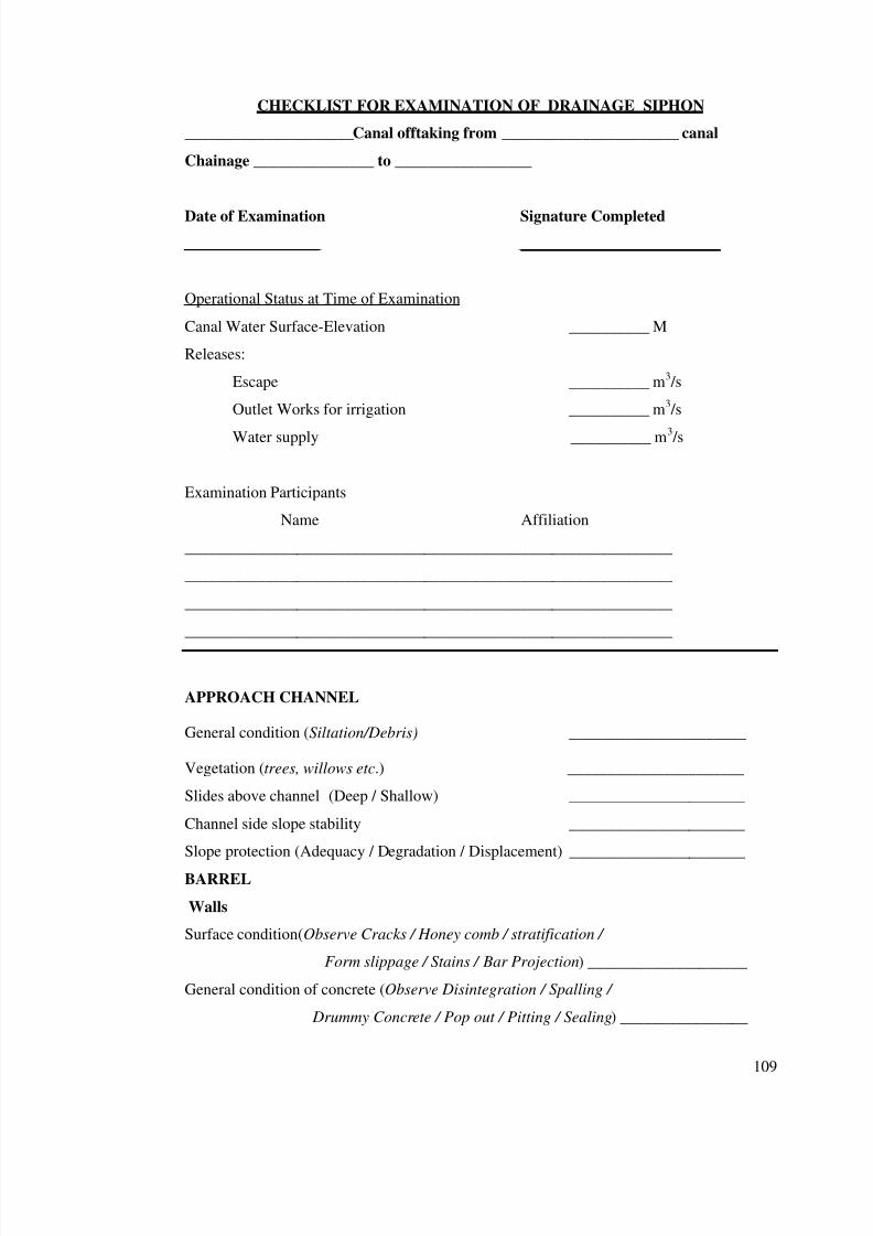
7/28/2019 Manual for Inspection of Structures
http://slidepdf.com/reader/full/manual-for-inspection-of-structures 111/156
109
CHECKLIST FOR EXAMINATION OF DRAINAGE SIPHON
_____________________Canal offtaking from ______________________ canal
Chainage _______________ to _________________
Date of Examination Signature Completed
_________________ _________________________
Operational Status at Time of Examination
Canal Water Surface-Elevation __________ M
Releases:
Escape __________ m3 /s
Outlet Works for irrigation __________ m3 /s
Water supply __________ m3 /s
Examination Participants
Name Affiliation
_____________________________________________________________
_____________________________________________________________
_____________________________________________________________
_____________________________________________________________
APPROACH CHANNEL
General condition (Siltation/Debris) ______________________
Vegetation (trees, willows etc.) ______________________
Slides above channel (Deep / Shallow) ______________________
Channel side slope stability ______________________
Slope protection (Adequacy / Degradation / Displacement) ______________________
BARREL
Walls
Surface condition(Observe Cracks / Honey comb / stratification /
Form slippage / Stains / Bar Projection) ____________________
General condition of concrete (Observe Disintegration / Spalling /
Drummy Concrete / Pop out / Pitting / Sealing) ________________
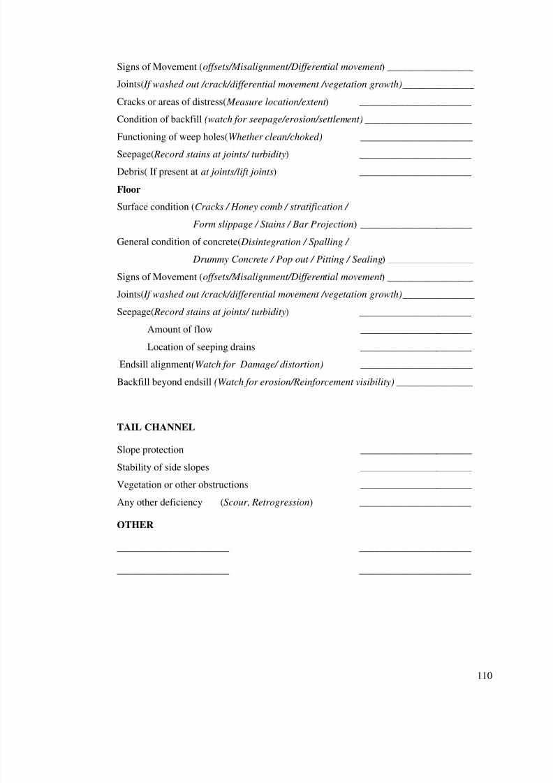
7/28/2019 Manual for Inspection of Structures
http://slidepdf.com/reader/full/manual-for-inspection-of-structures 112/156
110
Signs of Movement (offsets/Misalignment/Differential movement ) _________________
Joints( If washed out /crack/differential movement /vegetation growth) ______________
Cracks or areas of distress( Measure location/extent ) ______________________
Condition of backfill (watch for seepage/erosion/settlement) _____________________
Functioning of weep holes(Whether clean/choked) ______________________
Seepage( Record stains at joints/ turbidity) ______________________
Debris( If present at at joints/lift joints) ______________________
Floor
Surface condition (Cracks / Honey comb / stratification /
Form slippage / Stains / Bar Projection) ______________________
General condition of concrete( Disintegration / Spalling /
Drummy Concrete / Pop out / Pitting / Sealing) _________________
Signs of Movement (offsets/Misalignment/Differential movement ) _________________
Joints( If washed out /crack/differential movement /vegetation growth) ______________
Seepage( Record stains at joints/ turbidity) ______________________
Amount of flow ______________________
Location of seeping drains ______________________
Endsill alignment(Watch for Damage/ distortion) ______________________
Backfill beyond endsill (Watch for erosion/Reinforcement visibility) _______________
TAIL CHANNEL
Slope protection ______________________
Stability of side slopes ______________________
Vegetation or other obstructions ______________________
Any other deficiency (Scour, Retrogression) ______________________
OTHER
______________________ ______________________
______________________ ______________________
7/28/2019 Manual for Inspection of Structures
http://slidepdf.com/reader/full/manual-for-inspection-of-structures 113/156
111
Chapter 11
INSPECTION OF OUTLET WORKS (HEAD REGULATOR)
1. Outlet works are conduits through or around an
embankment used for releasing water. Regulated outlets use
gates or valves for controlling the rate of flow. At unregulated
conduits, the rate of flow is controlled by the size of the conduit
and the height of the water in the canal above the invert, or
floor, of the conduit. Conduits at embankments usually have
regulating gates or valves within the upstream portion of the
conduit so that flows can be shut off to prevent water from
eroding the embankment in the event of failure or leakage
through the conduit. Outlet works gates are susceptible to
plugging with debris and sediment deposition. Thus, it is
important that any trash racks in front of the gates be cleaned
whenever possible and that the gates be opened periodically to
flush debris and sediment.
INSPECTION ACTION:
Semiannual1y inspect the end of each outlet. Inspectthe outlet end of the conduit for breaks in the conduit,erosion of the downstream toe of the embankment orundercutting of the outlet end of the conduit.
Operate each gate sufficiently to ensure that it is fully
operable and debris and sediment are flushed out.
Inspect gate stems to the waterline, and correct any misalignment that interferes with operation.
Inspect downstream cistern of the outlets and get removeddebris/vegetation.
7/28/2019 Manual for Inspection of Structures
http://slidepdf.com/reader/full/manual-for-inspection-of-structures 114/156
7/28/2019 Manual for Inspection of Structures
http://slidepdf.com/reader/full/manual-for-inspection-of-structures 115/156
113
Misalignment of an intake structure - Misalignment may indicate movement of the abutments or other seriousstructure problem affecting the integrity of the canal.
4. In the paragraphs that follow, descriptions of the elements of
an intake structure are accompanied by specific points to check
during your inspection and recommendations to make in your
report.
Shaped Entrances:
5. Entrance in to or within intake structures are usually
rounded or otherwise specially shaped to streamline the flow of
water and minimize hydraulic. Even so, localized zones of
negative pressure resulting from rapid change in direction or
discontinuities can cause vibration and/or cavitation damage.
• Look for damaged concrete and exposed reinforcing steel.
Barrels, Outlet Pipes (Conduits)
6. A conduit is a pipe or box structure constructed by joining
sections.All outlets, HRs, canal siphons and drainage siphonscan generally be termed as conduits.
External Inspection Procedures for Conduits:
7. Evidence of potential conduit problems may be found by
examining external features of the conduit (if it is exposed) or
the embankment.
If the material is reaching its life expectancy, it may bepossible to dig down to expose all sides of the conduit at apoint where the surrounding soil is still damp. Examinethe outside of the conduit for signs of deterioration. Thecondition of the outside of the conduit could besignificantly different from the interior. In some cases thesoil protects the exterior from oxygen-induced corrosion.
7/28/2019 Manual for Inspection of Structures
http://slidepdf.com/reader/full/manual-for-inspection-of-structures 116/156
114
On the other hand local site conditions may haveaccelerated the deterioration of the exterior. Consider theoutside of the conduit to be just one indicator.
** Look for signs of infiltration of soil into the conduit:
Depression of the embankment along the centerline of theconduit.
Sinkholes and piping cavities that exit the surface. Holestaken over by animals may not be easily recognized assinkholes or piping cavities.
Holes that appear to be in a line. These may be an
indication that piping or settlement is occurring.
Fines in the discharged water.
** Look for seepage or indications that seepage is sometimespresent. (This is best done while the conduit is full).Indications of seepage are: Wet spots
Increased vegetation or the presence of plants that
thrive in wet ground.
** Watch for water flow when all intakes are closed. If any isobserved, double-check to see if intakes are leaking. If notdocument where water is entering the waterway, and examinethe water for fines.
** Look for piping related erosion around the conduit near thedownstream end. Check the embankment slope above theconduit outfall carefully for voids or erosion that may indicate
piping. Check for seepage adjacent to the structure. Thesituation may be especially serious if the seepage is carryingsediment.
** With exposed conduit, check the support for settlement of movement of the joints.
7/28/2019 Manual for Inspection of Structures
http://slidepdf.com/reader/full/manual-for-inspection-of-structures 117/156
115
** Check the concrete anchors of exposed steel conduit forcracking, weathering, and/or chemical deterioration.
Internal Inspection Procedures for Conduits:
8. To attempting to inspect conduit interiors, you may
experience the following difficulties:
** Dewatering difficulties: You cannot inspect a conduitcomprehensively unless it has been dewatered. However,dewatering may be impractical or impossible for one ormore of the following reasons.
- Lack of a bulkhead or other closure device.- The need to limit maximum drawdown
- The need to maintain water flows.- Structural inadequacy of the conduit to withstand
hydrostatic pressure in a dewatering condition.
To assess the probable condition of the conduit interior, it
may be necessary to rely on results of the exterior
inspection.
** Inaccessibility of conduit interior- The conduit may
betoo small or too dangerous for internal inspection by a
person. One possibility is to use remotely operated video
equipment. If that is not feasible, the inspection must be
based on:
- The condition of the exposed portion of the conduit orthe embankment above it.
- The internal inspection of accessible portions of theconduit. (some details can be observed from thedownstream end of the conduit with the aid of astrong light and possibly a mirror).
INSPECTION TIP : One indication of settlement related problems that may be observed from the downstream end if a conduit is the ponding of water in certain reaches of pipe.
7/28/2019 Manual for Inspection of Structures
http://slidepdf.com/reader/full/manual-for-inspection-of-structures 118/156
116
9. A deficiency commonly encountered in the internal inspection
of conduit is cracking. Be aware of previously reported cracks
and note any new cracks, using a crack map or similar reporting
method. Figure 6 shows one page of a crack map prepared by an inspection team. Cracks should be documented as fully as
possible, with measurements and/or sketches drawn to scale
showing the length and position of each crack. The crack map in
figure includes measurements of the depth of weep holes, which
were probed during the inspection.
10. To get some indication of whether cracks are continuousthrough a concrete structure, use a geologists' pick or other
hammer to tap the concrete. More comprehensive studies of the
concrete using dye tests and sonic methods may be necessary if
there are indications that the crack extends any distance into
the structure.
11. When inspecting the interior of a conduit, document thefollowing:
** Cavitation damage downstream, from gates and valves andat sharp bends, joints or other discontinuities.
** Corrosion of metal conduit or liner.** Cracking: Use crack maps, Describe position, length and
orientation (Transverse, longitudinal, or diagonal) Estimate
the depth of the crack.
** Damaged coating or lining materials. (Cracking or bucklingis a sign of structural stress Missing ### can causecavitation).
** Debris impact.
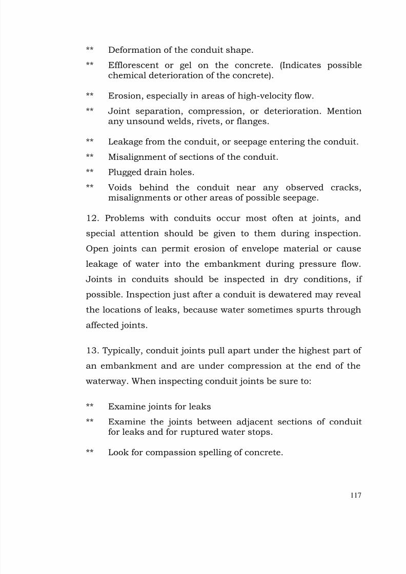
7/28/2019 Manual for Inspection of Structures
http://slidepdf.com/reader/full/manual-for-inspection-of-structures 119/156
117
** Deformation of the conduit shape.
** Efflorescent or gel on the concrete. (Indicates possiblechemical deterioration of the concrete).
** Erosion, especially in areas of high-velocity flow.** Joint separation, compression, or deterioration. Mention
any unsound welds, rivets, or flanges.
** Leakage from the conduit, or seepage entering the conduit.
** Misalignment of sections of the conduit.
** Plugged drain holes.
** Voids behind the conduit near any observed cracks,
misalignments or other areas of possible seepage.
12. Problems with conduits occur most often at joints, and
special attention should be given to them during inspection.
Open joints can permit erosion of envelope material or cause
leakage of water into the embankment during pressure flow.
Joints in conduits should be inspected in dry conditions, if
possible. Inspection just after a conduit is dewatered may reveal
the locations of leaks, because water sometimes spurts through
affected joints.
13. Typically, conduit joints pull apart under the highest part of
an embankment and are under compression at the end of the
waterway. When inspecting conduit joints be sure to:
** Examine joints for leaks
** Examine the joints between adjacent sections of conduitfor leaks and for ruptured water stops.
** Look for compassion spelling of concrete.
7/28/2019 Manual for Inspection of Structures
http://slidepdf.com/reader/full/manual-for-inspection-of-structures 120/156
118
** Check for misalignment of sections due to differentialsettlement.
Figure shown a conduit joint which has opened along the
bottom due to localized settlement along the conduit.
Operating Bridge And Pier Problems:
14. Deficiencies in the operating bridge, piers, decks, or otheraccess structures on the Head Regulator could make gates and
other controls unworkable in an emergency, and collapse of the
supporting structure could obstruct the Head Regulator.
15. Check for the following deficiencies.
On concrete bridges, check joints and water runoff points for exposed metal and corrosion of reinforcement
steel.
Check for peeling or missing paint
On steel flashing over joints inspect for break down of welds or mechanical connectors, couplings, and flanges.
Look for loose or insecurely anchored guardrails.
7/28/2019 Manual for Inspection of Structures
http://slidepdf.com/reader/full/manual-for-inspection-of-structures 121/156
119
Check the condition of previously repaired areas.
16. Check bridge support as follows.
On concrete bridge supports look for stress cracking.
Check the bearing supports at the abutments forcondition and evidence of movement.
Look for misalignment or damage at sliding joints.
Problems With Gates, Stoplogs:
17. When inspecting the control section of a Head Regulator/
Outlet, your primary concern is to ensure that the operation of
gates and other canal evacuation equipment is not impaired by
adjacent and supporting structures.
18. When inspecting, stoplogs and structures adjacent to and
supporting gates check the following points.
Look for displacement of structural elements orconcrete deterioration that may be jamming or
misalignment gates. Have the equipment operated if possible, to detect jamming, or gates not seatedproperly on the crest. During operations, look fordeterioration of material on the underside of thegates.
Note excessive leakage.
Watch for misalignment of gate stems and other signsof strain from holding water or from debris or overtightening.
Inspection of Gates and valves (annual).
(1) Visual inspection. –
When water conditions permit, inspect the downstreamsurfaces of the guard gate leaves and bodies, the
7/28/2019 Manual for Inspection of Structures
http://slidepdf.com/reader/full/manual-for-inspection-of-structures 122/156
120
upstream and downstream surfaces of regulating gateleaves and bodies, and outlet pipes.
Particular attention should be given to signs of cavitations damage to waterway surfaces downstream
from gate or valve leaves and flanged joints. Inspect neoprene or rubber gate seals for deterioration,
cracking, wear, foreign material deposits, and leakage.
Inspect valve and gates metal seats or seals for wear,scratches, foreign material deposits, and leakage.
Repairs should be made as necessary to keep theequipment in a safe and reliable operating condition.
(2) Exercising –
After lubrication, operate each valve and gate through afull cycle while under actual operating conditions, if possible.
During operation, listen for unusual noises and checkfor binding or vibration.
Inspection of Hydraulic and manual operators and control
systems for gates and valves (annual)
(1) Visual inspection -
Check hydraulic oil in the tank for proper fluid level(take into account displacement of the gate stem), water,and foreign materia1.
Check all pipe joints, cylinder flanges, packing, andhydraulic equipment for leaks.
Check oil filters and strainers and change or clean if required.
Check hydraulic hoist piston stem for rusting andforeign deposits. Remove deposits and rough areas onstems to prevent damage to packing or seals.

7/28/2019 Manual for Inspection of Structures
http://slidepdf.com/reader/full/manual-for-inspection-of-structures 123/156
121
(2)Exercising
Operate hydraulic control and manual operator systemsand check for unusual noises or vibrations.
Check motors and hydraulic fluids for overheating, andcheck pressure switches, pressure gages, and limitswitches for proper operation according to operatinginstructions.
Clean manual operators of dirt and foreign material andlubricate as appropriate.
20. Physical security - The physical security should be
inspected for adequacy and repairs and improvements made, as
necessary, to avoid unauthorized operation and ensure the
safety of the equipment.
Inspection of Traveling crane, hoist, and tracks (annual)
(3) Visual inspection
a. Examine hoist, crane, and tracks for broken, bent,misaligned, worn, or loose parts and corrosion anddeterioration of protective coatings.
(2)Exercising
b. After lubrication, operate crane and hoistthroughout all functions and check for unusual noises,binding, and vibration during operation.
7/28/2019 Manual for Inspection of Structures
http://slidepdf.com/reader/full/manual-for-inspection-of-structures 124/156
122
Chapter 12
INSPECTION OF CROSS REGULATOR
1. General inspection required as outlined vide Part II shall
apply for all the components of cross regulator. Following gives
further details for inspection to be carried out. Checklist for
inspection of cross regulator is provided at the end of this
chapter.
Operating Bridge And Pier Problems:
2. Deficiencies in the operating bridge, piers, decks, or other
access structures on the cross regulator could make gates and
other controls unworkable in an emergency, and collapse of the
supporting structure could obstruct the canal.
3. Check for the following deficiencies.
On concrete bridges, check joints and water runoff points for exposed metal and corrosion of reinforcementsteel.
Check for peeling or missing paint
On steel flashing over joints inspect for break down of welds or mechanical connectors, couplings, and flanges.
Look for loose or insecurely anchored guardrails.
Check the condition of previously repaired areas.
4.Check bridge support as follows.
On concrete bridge supports look for stress cracking.
7/28/2019 Manual for Inspection of Structures
http://slidepdf.com/reader/full/manual-for-inspection-of-structures 125/156
123
Check the bearing supports at the abutments forcondition and evidence of movement.
Look for misalignment or damage at sliding joints.
Problems With Gates, Stoplogs:
5.When inspecting the control section of an cross regulator,
your primary concern is to ensure that the operation of gates is
not impaired by adjacent and supporting structures.
6. When inspecting, stoplogs and structures adjacent to and
supporting gates check the following points.
Look for displacement of structural elements orconcrete deterioration that may be jamming ormisalignment gates. Have the equipment operated if possible, to detect jamming, or gates not seatedproperly on the crest. During operations, look fordeterioration of material on the underside of thegates.
Note excessive leakage.
Watch for misalignment of gate stems and other signs
of strain from holding water or from debris or overtightening.
Inspection of Gates and valves (annual).
(1)Visual inspection. –
a When water conditions permit, inspect the downstreamsurfaces of the guard gate leaves and bodies, theupstream and downstream surfaces of regulating gate
leaves and bodies, and outlet pipes
b Particular attention should be given to signs of cavitations damage to waterway surfaces downstreamfrom gate or valve leaves and flanged joints.
7/28/2019 Manual for Inspection of Structures
http://slidepdf.com/reader/full/manual-for-inspection-of-structures 126/156
124
c. Inspect neoprene or rubber gate seals for deterioration,cracking, wear, foreign material deposits, and leakage.
d. Inspect valve and gates metal seats or seals forwear, scratches, foreign material deposits, and leakage.
e. Repairs should be made as necessary to keep theequipment in a safe and reliable operating condition.
(2) Exercising –
After lubrication, operate each valve and gate through afull cycle while under actual operating conditions, if possible.
During operation, listen for unusual noises and checkfor binding or vibration.
Inspection of Hydraulic and manual operators and controlsystems for gates and valves (annual)
(1) Visual inspection -
Check hydraulic oil in the tank for proper fluid level(take into account displacement of the gate stem), water,
and foreign materia1.
Check all pipe joints, cylinder flanges, packing, andhydraulic equipment for leaks.
Check oil filters and strainers and change or clean if required.
Check hydraulic hoist piston stem for rusting andforeign deposits. Remove deposits and rough areas on
stems to prevent damage to packing or seals.
(2)Exercising
Operate hydraulic control and manual operator systemsand check for unusual noises or vibrations.
7/28/2019 Manual for Inspection of Structures
http://slidepdf.com/reader/full/manual-for-inspection-of-structures 127/156
125
Check motors and hydraulic fluids for overheating, andcheck pressure switches, pressure gages, and limitswitches for proper operation according to operatinginstructions.
Clean manual operators of dirt and foreign material andlubricate as appropriate.
7. Physical security - The physical security should be
inspected for adequacy and repairs and improvements made, as
necessary, to avoid unauthorized operation and ensure the
safety of the equipment.
Inspection of Traveling crane, hoist, and tracks (annual)
(1) Visual inspection
a. Examine hoist, crane, and tracks for broken, bent,misaligned, worn, or loose parts and corrosion anddeterioration of protective coatings.
(2)Exercising
b. After lubrication, operate crane and hoistthroughout all functions and check for unusual noises,binding, and vibration during operation.
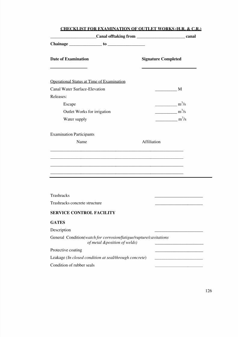
7/28/2019 Manual for Inspection of Structures
http://slidepdf.com/reader/full/manual-for-inspection-of-structures 128/156
126
CHECKLIST FOR EXAMINATION OF OUTLET WORKS (H.R. & C.R.)
_____________________Canal offtaking from ______________________ canal
Chainage _______________ to _________________
Date of Examination Signature Completed
_________________ _________________________
Operational Status at Time of Examination
Canal Water Surface-Elevation __________ M
Releases:
Escape __________ m3 /s
Outlet Works for irrigation __________ m3 /s
Water supply __________ m3 /s
Examination Participants
Name Affiliation
_____________________________________________________________
_____________________________________________________________
_____________________________________________________________
_____________________________________________________________
Trashracks ______________________
Trashracks concrete structure ______________________
SERVICE CONTROL FACILITY
GATES
Description ______________________
General Condition(watch for corrosion/fatigue/rupture/cavitationsof metal &position of welds) ______________________
Protective coating ______________________
Leakage (In closed condition at seal/through concrete) ______________________
Condition of rubber seals ______________________
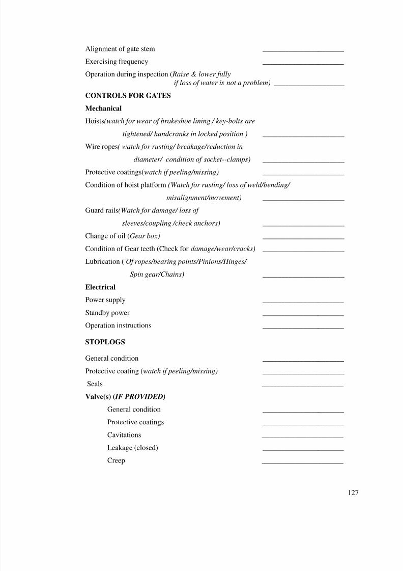
7/28/2019 Manual for Inspection of Structures
http://slidepdf.com/reader/full/manual-for-inspection-of-structures 129/156
127
Alignment of gate stem ______________________
Exercising frequency ______________________
Operation during inspection ( Raise & lower fully
if loss of water is not a problem) ___________________
CONTROLS FOR GATES
Mechanical
Hoists(watch for wear of brakeshoe lining / key-bolts are
tightened/ handcranks in locked position ) ______________________
Wire ropes( watch for rusting/ breakage/reduction in
diameter/ condition of socket--clamps) ______________________
Protective coatings(watch if peeling/missing) ______________________
Condition of hoist platform (Watch for rusting/ loss of weld/bending/
misalignment/movement) ______________________Guard rails(Watch for damage/ loss of
sleeves/coupling /check anchors) ______________________
Change of oil (Gear box) ______________________
Condition of Gear teeth (Check for damage/wear/cracks) ______________________
Lubrication ( Of ropes/bearing points/Pinions/Hinges/
Spin gear/Chains) ______________________
Electrical
Power supply ______________________
Standby power ______________________
Operation instructions ______________________
STOPLOGS
General condition ______________________
Protective coating (watch if peeling/missing) ______________________
Seals ______________________
Valve(s) ( IF PROVIDED)General condition ______________________
Protective coatings ______________________
Cavitations ______________________
Leakage (closed) ______________________
Creep ______________________
7/28/2019 Manual for Inspection of Structures
http://slidepdf.com/reader/full/manual-for-inspection-of-structures 130/156
128
Exercising frequency ______________________
Operation of valves at time of
examination ______________________
Control system for valves
Mechanical ______________________
Electrical ______________________
Operating instructions ______________________
GATE CIVIL WORKS (including Access Bridge)
Walls
Surface condition(Observe Cracks / Honey comb / stratification /
Form slippage / Stains / Bar Projection) ____________________
General condition of concrete (Observe Disintegration / Spalling /
Drummy Concrete / Pop out / Pitting / Sealing) ________________
Signs of Movement (offsets/Misalignment/Differential movement ) _________________
Joints( If washed out /crack/differential movement /vegetation growth) ______________
Cracks or areas of distress( Measure location/extent ) ______________________
Condition of backfill (watch for seepage/erosion/settlement) _____________________
Functioning of weep holes(Whether clean/choked) ______________________
Seepage( Record stains at joints/ turbidity) ______________________
Debris( If present at at joints/lift joints) ______________________Floor
Surface condition (Cracks / Honey comb / stratification /
Form slippage / Stains / Bar Projection) ______________________
General condition of concrete( Disintegration / Spalling /
Drummy Concrete / Pop out / Pitting / Sealing) _________________
Signs of Movement (offsets/Misalignment/Differential movement ) _________________
Joints( If washed out /crack/differential movement /vegetation growth) ______________
Seepage( Record stains at joints/ turbidity) ______________________
Amount of flow ______________________
Location of seeping drains ______________________
Endsill alignment(Watch for Damage/ distortion) ______________________
Backfill beyond endsill (Watch for erosion/Reinforcement visibility) _______________
7/28/2019 Manual for Inspection of Structures
http://slidepdf.com/reader/full/manual-for-inspection-of-structures 131/156
129
Chapter 13
.INSPECTION OF FALL
1. General inspection required as outlined vide Part II shall
apply for all the components of canal fall. Following gives further
details for inspection to be carried out. Checklist for inspection
of canal fall is provided at the end of this chapter.
CONTROL SECTION:
2. The control section is a particularly critical portion of a canal
fall as it receives flow of water from upstream and passes on
further downstream via energy dissipation system. It may be in
the form of a weir with crest (or sill level) raised above canal bed
level.
3. Problems typical to the canal fall control section include:
• Deterioration of surface materials:Check the following
points for deterioration in the control section:
Look at surfaces in areas of concentrated and highvelocity flows, such as near gates,(in case of fall cumCross regulator) for erosion.
Check areas near large gates for cracking in concrete,and tearing, rupture, and fatigue in metal.
Examine the upstream edges of weirs for damage frombattering by debris.
INSPECTION TIP : High velocity flow over a concrete surface containing abnormalities can initiate cavitation damage. Check surfaces carefully for offsets, small holes and calcium carbonate deposits. The bearing surfaces

7/28/2019 Manual for Inspection of Structures
http://slidepdf.com/reader/full/manual-for-inspection-of-structures 132/156
130
where gates rest and areas immediately downstream of gate slots, liner plates should be examined with special care.
• Obstructions: Besides general types of obstructionsalready discussed, check for the following obstructions to
control sections:
Check for unauthorized equipment added to the controlsection.
• Operating Bridge And Pier Problems:Deficiencies in theoperating bridge, piers, decks, or other access structureson the escape could make gates and other controlsunworkable and collapse of the supporting structure couldobstruct the canal.
Check for the following deficiencies.
On concrete bridges, check joints and water runoff points for exposed metal and corrosion of reinforcementsteel.
Check for peeling or missing paint
On steel flashing over joints inspect for break down of welds or mechanical connectors, couplings, and flanges.
Look for loose or insecurely anchored guardrails.
Check the condition of previously repaired areas.
Check bridge support as follows.
On concrete bridge supports look for stress cracking.
Check the bearing supports at the abutments for
condition and evidence of movement. Look for misalignment or damage at sliding joints.
• Problems With Gates, Stoplogs:
When inspecting the control section of a fall cum Cross
regulator, your primary concern is to ensure that the
7/28/2019 Manual for Inspection of Structures
http://slidepdf.com/reader/full/manual-for-inspection-of-structures 133/156
131
operation of gates is not impaired by adjacent and
supporting structures.
When inspecting, stoplogs and structures adjacent to and
supporting gates check the following points.
Look for displacement of structural elements orconcrete deterioration that may be jamming ormisalignment gates. Have the equipment operated if possible, to detect jamming, or gates not seatedproperly on the crest. During operations, look fordeterioration of material on the underside of thegates.
Note excessive leakage.
Watch for misalignment of gate stems and othersigns of strain from holding water or from debris orover tightening.
• Backfill and Foundation Deficiencies:
Points to remember when inspecting the control section
for backfill and foundation deficiencies are:
Foundation in the control section often must bear thestress of heavy equipment. Check carefully fordisplacements that may indicate settling foundationshifts, or undermining. Check for voids underconcrete channel walls and floors.
It is critical that gaps in joints do not exposefoundation or backfill material where escape extendsthrough the embankment section, and that waterstops, sealants and compressive joint fillers are intactand in good condition.
Check for clogged weep holes and foundation drains if present and watch for seepage and other signs of problems with the drainage system.
7/28/2019 Manual for Inspection of Structures
http://slidepdf.com/reader/full/manual-for-inspection-of-structures 134/156
132
Energy Dissipation Section:
4. Use these general guidelines during the your inspection of the
energy dissipation section of a canal fall:
First and foremost, know how the structures are supposedto function.
Make close observations of the structures when in use.Note unusual water currents, eddies and swirls, especially return currents that would carry rock and debris into thestructure from downstream.
Look for “Sand boils” which result from the upward flow of seepage under pressure and are characterized by a boiling
action of the surface seepage. A sand boil is oftenaccompanied by a cone of material around the boil whichdevelops from the deposition of foundation or embankmentmaterial varied by the seepage.
If possible, dewater the pool to inspect surfaces fordamage.
To inspect a large pool that cannot be dewatered, plan aboat inspection and record soundings made A plumb bob/
surveying equipment may be needed to determine thelocation of subsurface damage.
Underwater inspections by divers are recommended if problems are suspected. As with any underwaterinspection, a detailed inspection, a plan and a goodcommunication system are important considerations forlogging damaged areas.
Typical Problems With Energy Dissipation Section:
5. Damage can occur to all elements of an energy dissipation
section because these structures reduce the velocity and
dissipate the energy of a flow. If the energy dissipation structure
7/28/2019 Manual for Inspection of Structures
http://slidepdf.com/reader/full/manual-for-inspection-of-structures 135/156
133
fails to operate properly the main structure can be eroded at the
down stream end, causing a loss of foundation support.
6. Problems typical to the energy dissipation section include the
following:
Deteriaration of Materials:
7. Follow the actions described in Table--5- Inspection of Energy
Dissipation materials to check for deterioration of materials.
TABLE – 5 INSPECTION OF ENERGY DISSIPATION
MATERIALS
Concrete Check for signs of cavitation. Thesides of chute blocks baffles. Anddentates are exposed to considerableturbulence, and any offsets orirregularities can trigger cavitation.
Look for erosion damage fromabrasion of wasteweir aprons, the top
surfaces and undersides of buckets,and the floors, walls chute blocks anddentates of stilling basins.
See if ball milling has ground circularpatterns in the floor or apron of stilling / hydraulic jump basins.
Check joints for spells or settlementon one side. See if joint sealant or
compressive joint filler is crackedmissing, moved, or deteriorated. Lookfor broken waterstops.
Watch for corroded and damagedreinforcement resulting from erosionand cavitation damage. Concrete
7/28/2019 Manual for Inspection of Structures
http://slidepdf.com/reader/full/manual-for-inspection-of-structures 136/156
7/28/2019 Manual for Inspection of Structures
http://slidepdf.com/reader/full/manual-for-inspection-of-structures 137/156
135
9. Damaged Or Missing Baffles: Baffles may be cracked
severely eroded loose or missing.
10. Misalignment Of Walls Or Baffles: The force of flows may
deflect the portion of terminal structures.
Check for vertically, and sight along the top of a sill foralignment deviation.
Check instrumentation data to measure deflections.
Offsets may occur as a result of misalignment, and cavitation
can developed downstream of such offsets.
11. Malfunctioning Drains: Check for clogged drains in the
energy dissipation area. Determine whether water flowing from
drains is clear or contains sediment or fine materials.
12. Backfill And Foundation Deficiencies: Check the following
points when inspecting the energy dissipation section for
backfill and foundation deficiencies:
Inspect plunge pools, hydraulic jump basins, and riprap-lined dissipators carefully for foundation and crack fillproblems. Look for settlement and cracks in backfill.Measure the size and distance of problem areas measuresettlement depth and probe for voids and erosion channels.
Watch especially for erosion of backfill behind the
downstream portion of a stilling / hydraulic jump basinscutoff walls and reinforcement should not be visible.
Settlement or improper elevation or length may change the jump location is stilling / hydraulic jump basins. Checkthat jump within the structure occurs at design locations(If the escape or outlet works is not operating, water stains
7/28/2019 Manual for Inspection of Structures
http://slidepdf.com/reader/full/manual-for-inspection-of-structures 138/156
136
on the walls will indicate where the jump is actually occurring).
Look for misaligned dry walls, cracks in the basin, andcracked backfill for evidence that a jump basis is settling.
Check a riprap plunge pool for undermining by loss of underlying soil or lack of filter action.
If a plunge pool lining is sand or gravel, check for piping.
7/28/2019 Manual for Inspection of Structures
http://slidepdf.com/reader/full/manual-for-inspection-of-structures 139/156
137
CHECKLIST FOR EXAMINATION OF CANAL FALL STRUCTURE
_____________________Canal offtaking from ______________________ canal
Chainage _______________ to _________________
Date of Examination Signature Completed
_________________ _________________________
Operational Status at Time of Examination
Canal Water Surface-Elevation __________ M
Releases:
Escape __________ m3 /s
Outlet Works for irrigation __________ m3 /s
Water supply __________ m3 /s
Examination Participants
Name Affiliation
_____________________________________________________________
_____________________________________________________________
_____________________________________________________________
_____________________________________________________________
GLACIS OF WASTE WEIR/SPILLWAY
Debris ______________________
Crest
Surface condition(Cracks / Honey comb / stratification /
Form slippage / Stains / Bar Projection) ________________
General condition of concrete( Disintegration / Spalling /
Drummy Concrete / Pop out / Pitting / Sealing) __________________
Cracks or areas of distress ______________________
Sign of movement ______________________
Training Walls
Surface condition(Observe Cracks / Honey comb / stratification /
Form slippage / Stains / Bar Projection) ___________________
7/28/2019 Manual for Inspection of Structures
http://slidepdf.com/reader/full/manual-for-inspection-of-structures 140/156
138
General condition of concrete (Observe Disintegration / Spalling /
Drummy Concrete / Pop out / Pitting / Sealing) _______________
Signs of Movement (offsets/Misalignment/Differential movement ) ________________
Joints( If washed out /crack/differential movement /vegetation growth) _____________
Cracks or areas of distress( Measure location/extent ) ______________________
Condition of backfill (watch for seepage/erosion/settlement) _____________________
Functioning of weep holes(Whether clean/choked) ______________________
Seepage( Record stains at joints/ turbidity) ______________________
Debris( If present at at joints/lift joints) ______________________
Floor/apron/cistern
Surface condition (Cracks / Honey comb / stratification /
Form slippage / Stains / Bar Projection) ______________________
General condition of concrete( Disintegration / Spalling /
Drummy Concrete / Pop out / Pitting / Sealing) ________________
Signs of Movement (offsets/Misalignment/Differential movement ) _________________
Joints( If washed out /crack/differential movement /vegetation growth) ______________
Seepage( Record stains at joints/ turbidity) ______________________
Amount of flow ______________________
Location of seeping drains ______________________
Endsill alignment(Watch for Damage/ distortion) ______________________
Backfill beyond endsill (Watch for erosion/Reinforcement visibility) _______________
7/28/2019 Manual for Inspection of Structures
http://slidepdf.com/reader/full/manual-for-inspection-of-structures 141/156
139
Chapter 14
INSPECTION OF AQEDUCTS
1. General inspection required as outlined vide Part II shall
apply for all the components of canal aqueduct. Following gives
further details for inspection to be carried out. Checklist for
inspection of canal aqueduct is provided at the end of this
chapter.
2. Operating Bridge And Pier Problems:Deficiencies in theoperating bridge, piers, decks, or other access structures on theescape could make gates and other controls unworkable andcollapse of the supporting structure could obstruct the canal.
Check for the following deficiencies.
On concrete bridges, check joints and water runoff points for exposed metal and corrosion of reinforcementsteel.
Check for peeling or missing paint
On steel flashing over joints inspect for break down of welds or mechanical connectors, couplings, and flanges.
Look for loose or insecurely anchored guardrails.
Check the condition of previously repaired areas.
Check bridge support as follows.
On concrete bridge supports look for stress cracking.
Check the bearing supports at the abutments forcondition and evidence of movement.
Look for misalignment or damage at sliding joints.
7/28/2019 Manual for Inspection of Structures
http://slidepdf.com/reader/full/manual-for-inspection-of-structures 142/156
140
Problems With Gates, Stoplogs:
3. When inspecting the control section of a fall cum Cross
regulator, your primary concern is to ensure that the operation
of gates is not impaired by adjacent and supporting structures.
4. When inspecting, stoplogs and structures adjacent to and
supporting gates check the following points.
Look for displacement of structural elements orconcrete deterioration that may be jamming ormisalignment gates. Have the equipment operated if
possible, to detect jamming, or gates not seatedproperly on the crest. During operations, look fordeterioration of material on the underside of thegates. Note excessive leakage.
Watch for misalignment of gate stems and othersigns of strain from holding water or from debris orover tightening.
Backfill and Foundation Deficiencies:
5. Points to remember when inspecting the control section for
backfill and foundation deficiencies are:
Foundation in the control section often must bear thestress of heavy equipment. Check carefully fordisplacements that may indicate settling foundationshifts, or undermining. Check for voids underconcrete channel walls and floors.
It is critical that gaps in joints do not exposefoundation or backfill material where escape extendsthrough the embankment section, and that waterstops, sealants and compressive joint fillers are intactand in good condition.
7/28/2019 Manual for Inspection of Structures
http://slidepdf.com/reader/full/manual-for-inspection-of-structures 143/156
141
Check for clogged weep holes and foundation drains if present and watch for seepage and other signs of problems with the drainage system.
Inspection of Aqueduct Barrels:
External Inspection Procedures:
6. Evidence of potential problems may be found by examining
external features of the barrels.
Examine the outside of the barrel for signs of deterioration. The condition of the outside of the barrel could be
significantly different from the interior e.g. local siteconditions might have accelerated the deterioration of theexterior. Consider the outside of the conduit to be just oneindicator.
** Look for seepage or indications that seepage is sometimespresent. (This is best done while the barrel is full).Indications of seepage are: Wet spots
Increased vegetation or the presence of plants thatthrive in wet ground.
** Watch for water flow when all intakes are closed. If any isobserved, double-check to see if intakes are leaking. If notdocument where water is entering the barrel, and examinethe water for fines.
** Check for seepage adjacent to the structure. The situationmay be especially serious if the seepage is carrying sediment.
** With exposed conduit, check the support for settlement of movement of the joints.
** Check the concrete anchors of exposed steel conduit forcracking, weathering, and/or chemical deterioration.

7/28/2019 Manual for Inspection of Structures
http://slidepdf.com/reader/full/manual-for-inspection-of-structures 144/156
142
Internal Inspection Procedures:
7. To attempting to inspect barrel interiors, you may experience
the following difficulties:
** Dewatering difficulties: You cannot inspect a barrelcomprehensively unless it has been dewatered. However,dewatering may be impractical or impossible for one ormore of the following reasons.
- The need to limit maximum drawdown
- The need to maintain water flows.
- Structural inadequacy of the barrel to withstandhydrostatic pressure in a dewatering condition.
To assess the probable condition of the barrel interior, it
may be necessary to rely on results of the exterior
inspection.
** Inaccessibility of conduit interior- The conduit may be
too dangerous for internal inspection by a person. One
possibility is to use remotely operated video equipment. If
that is not feasible, the inspection must be based on:
- The condition of the exposed portion of the barrel
- The internal inspection of accessible portions of thebarrel. (some details can be observed from thedownstream end of the barrel with the aid of a stronglight and possibly a mirror).
INSPECTION TIP : One indication of settlement related
problems that may be observed from the downstream end if a conduit is the ponding of water in certain reaches of barrel.
8. A deficiency commonly encountered in the internal inspection
of barrel is cracking. Be aware of previously reported cracks and
7/28/2019 Manual for Inspection of Structures
http://slidepdf.com/reader/full/manual-for-inspection-of-structures 145/156
143
note any new cracks, using a crack map or similar reporting
method. Figure -6 shows one page of a crack map prepared by
an inspection team. Cracks should be documented as fully as
possible, with measurements and/or sketches drawn to scaleshowing the length and position of each crack. The crack map in
figure includes measurements of the depth of weep holes, which
were probed during the inspection.
9. To get some indication of whether cracks are continuous
through a concrete structure, use a geologists' pick or other
hammer to tap the concrete. More comprehensive studies of theconcrete using dye tests and sonic methods may be necessary if
there are indications that the crack extends any distance into
the structure.
10 When inspecting the interior of a barrel, document the
following:
** Cavitation damage downstream, at joints or otherdiscontinuities.
** Corrosion of metal conduit or liner.** Cracking: Use crack maps, Describe position, length and
orientation (Transverse, longitudinal, or diagonal) Estimatethe depth of the crack.
** Debris impact.
** Deformation of the barrel shape.
** Efflorescent or gel on the concrete. (Indicates possiblechemical deterioration of the concrete).
** Erosion, especially in areas of high-velocity flow.
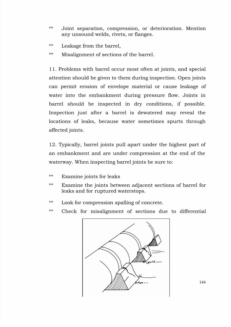
7/28/2019 Manual for Inspection of Structures
http://slidepdf.com/reader/full/manual-for-inspection-of-structures 146/156
144
** Joint separation, compression, or deterioration. Mentionany unsound welds, rivets, or flanges.
** Leakage from the barrel,
** Misalignment of sections of the barrel.
11. Problems with barrel occur most often at joints, and special
attention should be given to them during inspection. Open joints
can permit erosion of envelope material or cause leakage of
water into the embankment during pressure flow. Joints in
barrel should be inspected in dry conditions, if possible.
Inspection just after a barrel is dewatered may reveal thelocations of leaks, because water sometimes spurts through
affected joints.
12. Typically, barrel joints pull apart under the highest part of
an embankment and are under compression at the end of the
waterway. When inspecting barrel joints be sure to:
** Examine joints for leaks
** Examine the joints between adjacent sections of barrel forleaks and for ruptured waterstops.
** Look for compression spalling of concrete.
** Check for misalignment of sections due to differential
7/28/2019 Manual for Inspection of Structures
http://slidepdf.com/reader/full/manual-for-inspection-of-structures 147/156
145
settlement.Figure shows a barrel joint which has opened along the bottom
due to localized settlement along the barrel.
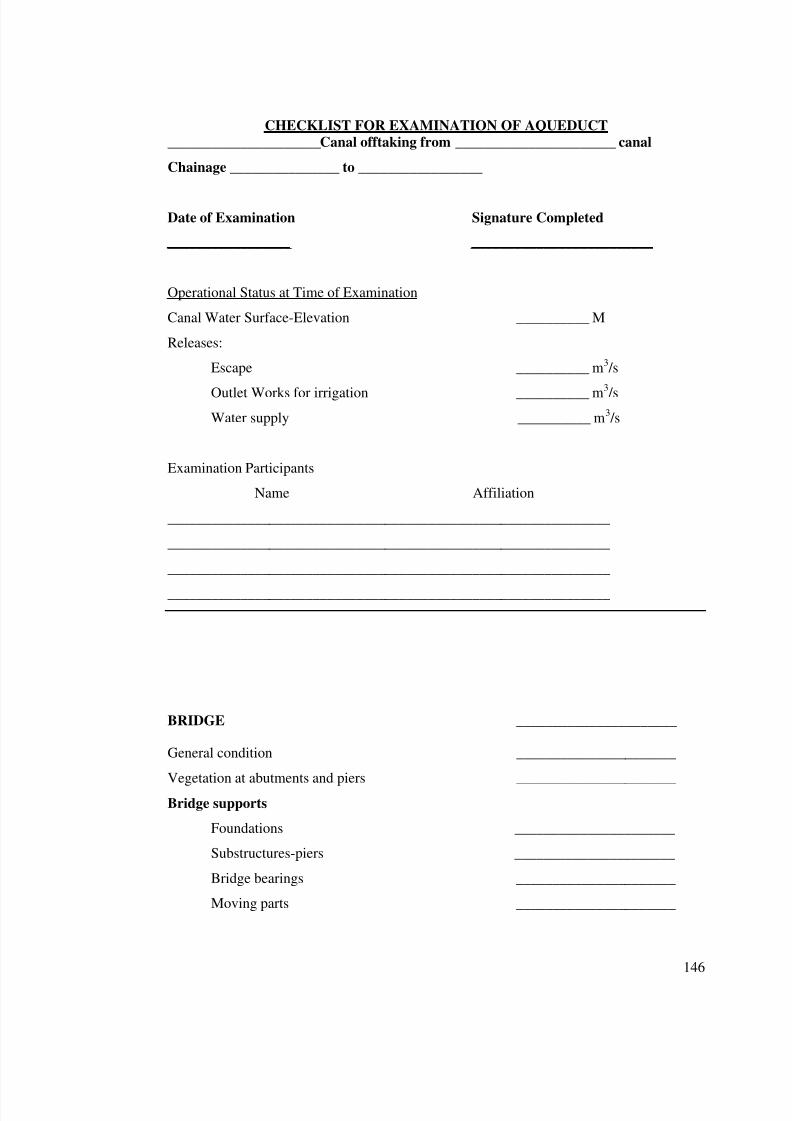
7/28/2019 Manual for Inspection of Structures
http://slidepdf.com/reader/full/manual-for-inspection-of-structures 148/156
146
CHECKLIST FOR EXAMINATION OF AQUEDUCT
_____________________Canal offtaking from ______________________ canal
Chainage _______________ to _________________
Date of Examination Signature Completed
_________________ _________________________
Operational Status at Time of Examination
Canal Water Surface-Elevation __________ M
Releases:
Escape __________ m3 /s
Outlet Works for irrigation __________ m3
/s
Water supply __________ m3 /s
Examination Participants
Name Affiliation
_____________________________________________________________
_____________________________________________________________
_____________________________________________________________
_____________________________________________________________
BRIDGE ______________________
General condition ______________________
Vegetation at abutments and piers ______________________
Bridge supports
Foundations ______________________
Substructures-piers ______________________
Bridge bearings ______________________
Moving parts ______________________
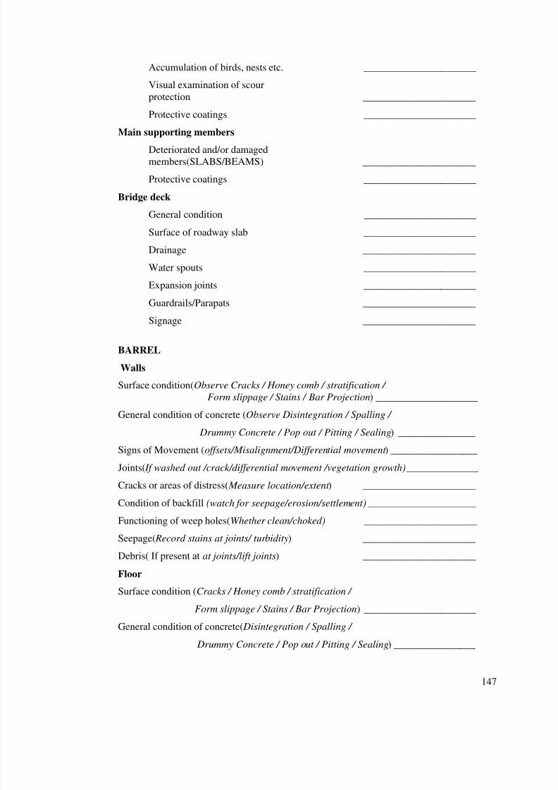
7/28/2019 Manual for Inspection of Structures
http://slidepdf.com/reader/full/manual-for-inspection-of-structures 149/156
147
Accumulation of birds, nests etc. ______________________
Visual examination of scour
protection ______________________
Protective coatings ______________________
Main supporting members
Deteriorated and/or damaged
members(SLABS/BEAMS) ______________________
Protective coatings ______________________
Bridge deck
General condition ______________________
Surface of roadway slab ______________________
Drainage ______________________
Water spouts ______________________
Expansion joints ______________________
Guardrails/Parapats ______________________
Signage ______________________
BARREL
Walls
Surface condition(Observe Cracks / Honey comb / stratification /
Form slippage / Stains / Bar Projection) ____________________
General condition of concrete (Observe Disintegration / Spalling /
Drummy Concrete / Pop out / Pitting / Sealing) _______________
Signs of Movement (offsets/Misalignment/Differential movement ) _________________
Joints( If washed out /crack/differential movement /vegetation growth) ______________
Cracks or areas of distress( Measure location/extent ) ______________________
Condition of backfill (watch for seepage/erosion/settlement) _____________________
Functioning of weep holes(Whether clean/choked) ______________________
Seepage( Record stains at joints/ turbidity) ______________________
Debris( If present at at joints/lift joints) ______________________
Floor
Surface condition (Cracks / Honey comb / stratification /
Form slippage / Stains / Bar Projection) ______________________
General condition of concrete( Disintegration / Spalling /
Drummy Concrete / Pop out / Pitting / Sealing) ________________
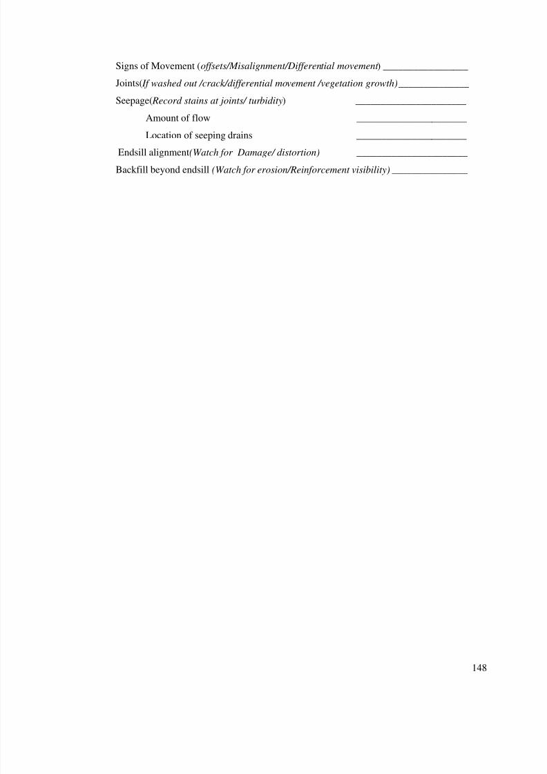
7/28/2019 Manual for Inspection of Structures
http://slidepdf.com/reader/full/manual-for-inspection-of-structures 150/156
148
Signs of Movement (offsets/Misalignment/Differential movement ) _________________
Joints( If washed out /crack/differential movement /vegetation growth) ______________
Seepage( Record stains at joints/ turbidity) ______________________
Amount of flow ______________________
Location of seeping drains ______________________
Endsill alignment(Watch for Damage/ distortion) ______________________
Backfill beyond endsill (Watch for erosion/Reinforcement visibility) _______________

7/28/2019 Manual for Inspection of Structures
http://slidepdf.com/reader/full/manual-for-inspection-of-structures 151/156
149
PART IV
SCHEDULE OF ROUTINE INSPECTION
7/28/2019 Manual for Inspection of Structures
http://slidepdf.com/reader/full/manual-for-inspection-of-structures 152/156
150
Chapter 15
SCHEDULE OF ROUTINE INSPECTION
1. Operation of the dam/canal during normal conditions shallbe the responsibility of the section officer in charge of the canal.It shall be ensured that unauthorized encroachments do notoccur, that existing or potential conditions do not lead to publiccriticism or injury to the public and that nothing is done whichconflicts with the primary purpose of the project. Following givesschedule of duties to be performed by the Section officer:
Daily
1. Record water surface elevation in reservoir/canal2. Record discharge released into various canals/ direct outlets
offtaking from the canal within his jurisdiction3. Record releases from escapes/wasteweirs/spillways4. Check security and safety devices5. Make required changes in gate openings6. Record pertinent information in Operating Log7. Check escape tail channel for debris
Monthly
1. Check condition of :Downstream cisterns
2. Run generators for minimum one hour3. Keep batteries charged4. Replace light bulbs if required5.Check signs that warn public of hazards near falls, escapes,
Head regulators and siphons6. Check fence conditions and caution signs
Quarterly
1. Operating instructions--uptodate & legible2. Clean gate control switchboxes3. Check & clear bridge drains4. Clean inside of motor control cabinet
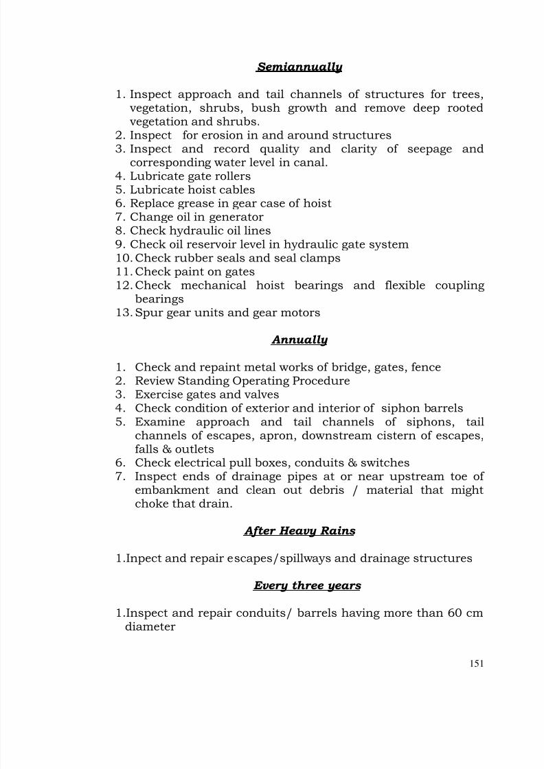
7/28/2019 Manual for Inspection of Structures
http://slidepdf.com/reader/full/manual-for-inspection-of-structures 153/156
151
Semiannually
1. Inspect approach and tail channels of structures for trees,vegetation, shrubs, bush growth and remove deep rootedvegetation and shrubs.
2. Inspect for erosion in and around structures3. Inspect and record quality and clarity of seepage and
corresponding water level in canal.4. Lubricate gate rollers5. Lubricate hoist cables6. Replace grease in gear case of hoist7. Change oil in generator8. Check hydraulic oil lines9. Check oil reservoir level in hydraulic gate system10. Check rubber seals and seal clamps
11. Check paint on gates12. Check mechanical hoist bearings and flexible coupling
bearings13. Spur gear units and gear motors
Annually
1. Check and repaint metal works of bridge, gates, fence2. Review Standing Operating Procedure3. Exercise gates and valves
4. Check condition of exterior and interior of siphon barrels5. Examine approach and tail channels of siphons, tail
channels of escapes, apron, downstream cistern of escapes,falls & outlets
6. Check electrical pull boxes, conduits & switches7. Inspect ends of drainage pipes at or near upstream toe of
embankment and clean out debris / material that mightchoke that drain.
After Heavy Rains
1.Inpect and repair escapes/spillways and drainage structures
Every three years
1.Inspect and repair conduits/ barrels having more than 60 cmdiameter
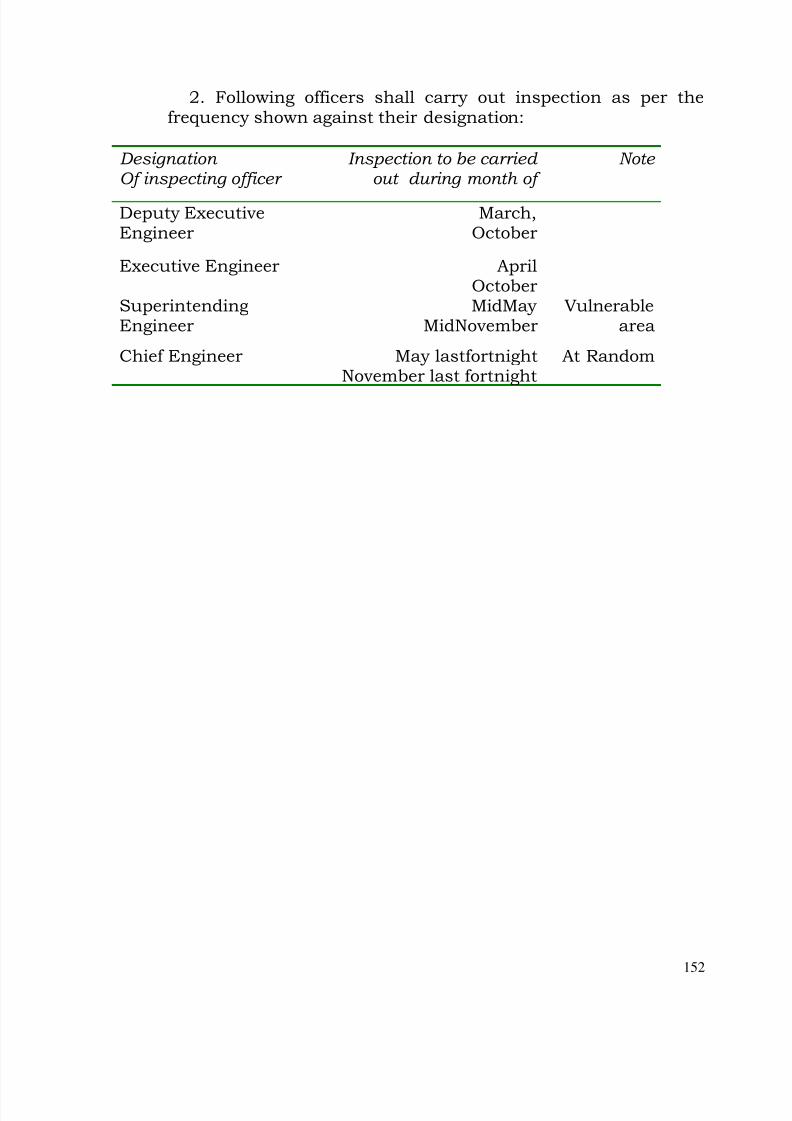
7/28/2019 Manual for Inspection of Structures
http://slidepdf.com/reader/full/manual-for-inspection-of-structures 154/156
152
2. Following officers shall carry out inspection as per thefrequency shown against their designation:
Designation Of inspecting officer
Inspection to be carried out during month of
Note
Deputy ExecutiveEngineer
March,October
Executive Engineer AprilOctober
SuperintendingEngineer
MidMay MidNovember
Vulnerablearea
Chief Engineer May lastfortnightNovember last fortnight
At Random
7/28/2019 Manual for Inspection of Structures
http://slidepdf.com/reader/full/manual-for-inspection-of-structures 155/156
153
PART V
INSPECTION DURING EMERGENCY
7/28/2019 Manual for Inspection of Structures
http://slidepdf.com/reader/full/manual-for-inspection-of-structures 156/156
Chapter 16
INSPECTION DURING EMERGENCY
Detailed guidelines are under preparation for inspection and operation
during emergency situations. These form part of Standing Operating
Procedures of each of the dams.
Related Documents