Manual for Computerboard ADL120 0.3 02.04.2019 Version: Date: Preliminary

Welcome message from author
This document is posted to help you gain knowledge. Please leave a comment to let me know what you think about it! Share it to your friends and learn new things together.
Transcript

Manual for Computerboard
ADL120
0.302.04.2019
Version:Date:
Prelim
inary

Prelim
inary

ADL120 3Version: 0.3
1 Documentation issue status..................................................................................................................... 7
2 Notes on the documentation .................................................................................................................... 8
3 Safety instructions .................................................................................................................................... 9
4 Overview................................................................................................................................................... 104.1 Properties ........................................................................................................................................ 104.2 List of features ................................................................................................................................. 114.3 Specifications and documents......................................................................................................... 12
5 Detailed description ................................................................................................................................ 135.1 Power supply ................................................................................................................................... 135.2 CPU ................................................................................................................................................. 135.3 Memory............................................................................................................................................ 135.4 M.2................................................................................................................................................... 13
6 External connections .............................................................................................................................. 146.1 Note on the use of cables................................................................................................................ 146.2 Connector Map ................................................................................................................................ 156.3 Interface list ..................................................................................................................................... 166.4 Front panel: Power supply (X101) ................................................................................................... 176.5 Front panel: LAN1-4 (X102-X105)................................................................................................... 186.6 Front panel: USB 3.0 A-D (X106 - X109) ........................................................................................ 196.7 Front panel: DisplayPort (X110, X110)............................................................................................ 20
7 Internal connections................................................................................................................................ 217.1 Internal: M.2..................................................................................................................................... 217.2 Internal: BAseCon140 (Q170 only).................................................................................................. 247.3 Internal: FAN ................................................................................................................................... 287.4 Internal: Battery ............................................................................................................................... 29
8 LEDs.......................................................................................................................................................... 308.1 LED: Power controller...................................................................................................................... 308.2 LED: SATA ...................................................................................................................................... 318.3 LED: TwinCAT................................................................................................................................. 328.4 LED: UPS-OCT................................................................................................................................ 33
9 BIOS.......................................................................................................................................................... 349.1 Main................................................................................................................................................. 349.2 Advanced Menu............................................................................................................................... 359.3 Platform Misc Configuration ............................................................................................................ 369.4 CPU Configuration........................................................................................................................... 379.5 CPU Power Management Control ................................................................................................... 389.6 Intel Ethernet Connection ................................................................................................................ 389.7 NIC Configuration ............................................................................................................................ 399.8 Driver Health.................................................................................................................................... 399.9 Intel Gigabit ..................................................................................................................................... 399.10 Trusted Computing .......................................................................................................................... 409.11 Hardware Monitor ............................................................................................................................ 40
Prelim
inary

ADL1204 Version: 0.3
9.12 PCI Subsystem Settings.................................................................................................................. 419.13 PCI Hot-Plug Settings...................................................................................................................... 419.14 Network Stack Configuration ........................................................................................................... 429.15 Power Controller Options ................................................................................................................ 439.16 CSM Configuration .......................................................................................................................... 449.17 NVMe Configuration ........................................................................................................................ 459.18 USB Configuration........................................................................................................................... 459.19 SATA und RST Configuration.......................................................................................................... 469.20 Software Feature Mask Configuration ............................................................................................. 479.21 AMT Configuration........................................................................................................................... 489.22 CIRA Configuration.......................................................................................................................... 489.23 ASF Configuration ........................................................................................................................... 499.24 Secure Erase Configuration ............................................................................................................ 499.25 OEM Flags Settings......................................................................................................................... 509.26 MEBx Resolution Settings ............................................................................................................... 519.27 Chipset ............................................................................................................................................ 519.28 System Agent (SA) Configuration.................................................................................................... 529.29 Graphics Configuration.................................................................................................................... 539.30 External Gfx Card Primary Display Configuration ........................................................................... 549.31 LCD Control ..................................................................................................................................... 549.32 PCH-IO Configuration...................................................................................................................... 559.33 PCI Express Configuration .............................................................................................................. 569.34 PCI Express Gen3 Eq Lanes........................................................................................................... 569.35 PCI Express Root Port X ................................................................................................................. 579.36 Extra Options................................................................................................................................... 589.37 USB Configuration........................................................................................................................... 589.38 HD Audio Configuration................................................................................................................... 599.39 Security............................................................................................................................................ 599.40 Secure Boot ..................................................................................................................................... 609.41 Key Management ............................................................................................................................ 609.42 Boot ................................................................................................................................................. 619.43 Fixed Boot Order Parameters.......................................................................................................... 629.44 Save & Exit ...................................................................................................................................... 62
10 Mechanical drawings .............................................................................................................................. 6310.1 PCB: Holes ...................................................................................................................................... 6310.2 PCB: Pin 1 distances....................................................................................................................... 6410.3 PCB: Dimensions ............................................................................................................................ 65
11 Technical data.......................................................................................................................................... 6611.1 Electrical data .................................................................................................................................. 6611.2 Environmental conditions ................................................................................................................ 6611.3 Technical specifications................................................................................................................... 67
12 Support .................................................................................................................................................... 6812.1 ADL Support ............................................................................................................................. 68
Prelim
inary

ADL120 5Version: 0.3
13 Appendix I: Post Codes .......................................................................................................................... 69
14 Appendix II: Resources........................................................................................................................... 7014.1 Interrupt ........................................................................................................................................... 7014.2 PCI Devices..................................................................................................................................... 7114.3 SMB-Devices................................................................................................................................... 72
Prelim
inary

ADL1206 Version: 0.3
Prelim
inary

Documentation issue status
ADL120 7Version: 0.3
1 Documentation issue statusVersion Modifications0.1 Preliminary version0.2 Preliminary version, change of the fan plug from 3 to 4-pin, OCT UPS, OCT LED inserted,
graphics for LEDs changed, mechanical drawings updated0.3 Interface assignment added
Prelim
inary

Notes on the documentation
ADL1208 Version: 0.3
2 Notes on the documentationThis description is only intended for the use of trained specialists in control and automation engineering who are familiar with the applicable national standards.It is essential that the documentation and the following notes and explanations are followed when installing and commissioning the components. It is the duty of the technical personnel to use the documentation published at the respective time of each installation and commissioning.
The responsible staff must ensure that the application or use of the products described satisfy all the requirements for safety, including all the relevant laws, regulations, guidelines and standards.
Disclaimer
The documentation has been prepared with care. The products described are, however, constantly under development.We reserve the right to revise and change the documentation at any time and without prior announcement. No claims for the modification of products that have already been supplied may be made on the basis of the data, diagrams and descriptions in this documentation.
Warranty
This product is warranted to be free of defects in workmanship and material. ADL Embedded Solutions' sole obligation under this warranty is to provide replacement parts or repair services at no charge, except shipping cost. Such defects which appear within 12 months of original shipment of ADL Embedded Solutions will be covered, provided a written claim for service under warranty is received by ADL Embedded Solutions no less then 30 days prior to the end of the warranty period of within 30 days of discovery of the defect – whichever comes first. Warranty coverage is contingent upon proper handling and operation of the product. Improper use such as unauthorized modifications or repair, operation outside of specified ratings, or physical damage may void any service claims under warranty.
Return Authorization
All equipment returned to ADL Embedded Solutions for evaluation, repair, credit return, modification, or any other reason must be accompanied by a Return Material Authorization (RMA) number. ADL Embedded Solutions requires a completed RMA request form to be submitted in order to issue an RMA number. The form can be found under the Support section at our website: www.adl-usa.com or www.adl-europe.com. Submit the completed form to [email protected] or fax to +1 858-490-0599 for the USA office, or to [email protected] or fax to +49 (0) 271 250 810 20 to request an RMA from the European office in Germany. Following a review of the information provided, ADL Embedded Solutions will issue an RMA number. Prel
imina
ry

Safety instructions
ADL120 9Version: 0.3
3 Safety instructionsSafety regulations
Please note the following safety instructions and explanations!Product-specific safety instructions can be found on following pages or in the areas mounting, wiring, commissioning etc.
Exclusion of liability
All the components are supplied in particular hardware and software configurations appropriate for the application. Modifications to hardware or software configurations other than those described in the documentation are not permitted, and nullify the liability of ADL Embedded Solutions.
Personnel qualification
This description is only intended for trained specialists in control, automation and drive engineering who are familiar with the applicable national standards.
Description of symbols
In this documentation the following symbols are used with an accompanying safety instruction or note. The safety instructions must be read carefully and followed without fail!
DANGERSerious risk of injury!Failure to follow the safety instructions associated with this symbol directly endangers the life and health ofpersons.
WARNINGRisk of injury!Failure to follow the safety instructions associated with this symbol endangers the life and health of per-sons.
CAUTIONPersonal injuries!Failure to follow the safety instructions associated with this symbol can lead to injuries to persons.
NOTEDamage to the environment or devicesFailure to follow the instructions associated with this symbol can lead to damage to the environment orequipment.
Tip or pointerThis symbol indicates information that contributes to better understanding.
Prelim
inary

Overview
ADL12010 Version: 0.3
4 Overview
4.1 PropertiesThe ADL120 is designed as a high-performance compact board based on Intel®'s Skylake and Kabylake processors. The latest energy-saving DDR4 technology enables memory extension of up to 32 GB via SO-DIMM260.
As standard interfaces two DisplayPort connections, four Gigabit LAN connections and four USB 3.0 interfaces are available on the front panel. The two DisplayPorts++ enable the connection of an HDMI adapter for an HDMI signal. The connection of an HDMI display with adapter is possible.
Two variants are available, variant 1 being equipped with a Q170 chipset and variant 2 with an H110 chipset.
Internally both variants of the ADL120 have two M.2 (B) sockets (2280), while variant 1 additionally has a BAseCon140 connector. Various signals, which are listed in the respective chapter, are led out via the internal plug connector depending on the chipset in use.
Power is supplied via a 4-pin connector on the front panel. Input voltage is isolated 24 V.
Fig. 1: Block diagram_ADL120
Prelim
inary

Overview
ADL120 11Version: 0.3
4.2 List of featuresADL120 120 x 120 boardCPU Intel® Core™ i3 / Core™ i5 / Core™ i7
Intel® Pentium®Intel® Celeron®
Memory 2x SO-DIMM260 1.2V DDR4-2133Maximum memory extension 32 GB
I/O on front panel 2x DisplayPort++ (connection of an HDMI adapter foran HDMI signal is possible.)4x GB LAN4x USB 3.0
Internal I/O 2x M.2 (B) sockets, signals dependent on chipsetInternal: M.2 [} 21]
With Q170 only: 1x BAseCon140 Internal:BAseCon140 (Q170 only) [} 24]
Graphic resolution DisplayPort: 4096x2304@60 HzHDMI1.4: 2560x1600@60 Hz; 4096x2160@24 HzDVI: 1920x1200@60 Hz
RTC Exchangeable, horizontal on-board batteryOptional: horizontal battery on expansion card
BIOS AMI® Aptio VPower supply 24 VFormat 120 x 120 mm
Availability of the processorsThe list of features lists all the processors that can be ordered. Their actual availability depends onthe manufacturer.
Prelim
inary

Overview
ADL12012 Version: 0.3
4.3 Specifications and documentsThe following documents, specifications or webpages were used for the preparation of this manual or asfurther technical documentation respectively.
• PCI specification• Version 2.3 or 3.0• www.pcisig.com• PCI Express® Base Specification• Version 2.0• www.pcisig.com• ACPI specification• Version 3.0• www.acpi.info• ATA/ATAPI specification• Version 7 Rev. 1• www.t13.org• USB specifications• www.usb.org• SM-Bus specification• Version 2.0• www.smbus.org• Intel® chip descriptions• Intel® Atom™ Processor E3800 Product Family datasheet• www.intel.com• Intel® chip description• i210 datasheet• www.intel.com• SMSC® chip description• SCH3114 datasheet (NDA required)• www.smsc.com• American Megatrends®• Aptio™ Text Setup Environment (TSE) User Manual• www.ami.com• American Megatrends®• Aptio™ 4.x Status Codes• www.ami.com
Prelim
inary

Detailed description
ADL120 13Version: 0.3
5 Detailed description
5.1 Power supplyThe board is supplied with an isolated input voltage of nominally 24 V, which in reality may lie between 20 Vand 30 V. In normal operation the DC/DC power rail is supplied with this voltage. A UPS can also beimplemented via an OCT signal (OCT = One Cable Technology).
UPS-OCTThe UPS-OCT can only be implemented with the Beckhoff CU81XX-xxxx UPS.
5.2 CPUThe processors employed are Intel® processors of the 6th (Skylake) and 7th (KabyLake) generation.Processors of both generations are characterized by a very low power consumption and offer contemoporaryperformance with clock rates of currently up to 3.9 GHz.
5.3 MemorySO-DIMM260 memory modules (DDR4-2133) commonly used in notebooks are used on the ADL120 board. For technical and mechanical reasons it is possible that certain memory modules cannot be used. Ask your distributor about the recommended memory modules.
With the currently available SO-DIMM260 modules a memory extension up to 32 GB is possible depending on the product variant. When equipping both memory sockets, care must be taken that identical memory modules are used.
5.4 M.2Expansion cards that fulfill the M.2 specification are characterized by an extremely small format and –depending on the card type – flexible dimensions.
M.2 cards can easily and simply be inserted by plugging them into the slot and fixing them with a screw.
The M.2 socket of the ADL120 supports Key B. Different signals are supported depending on the chipset in use. The table in chapter M.2 lists all the interfaces supported, depending on the chipset in use.
Driver compatibilityFor optimum driver compatibility we recommend the use of a Microsoft® Windows 10operating system.
Prelim
inary

External connections
ADL12014 Version: 0.3
6 External connections
6.1 Note on the use of cablesRequirement for the cabling!The cables used must meet certain requirements for most interfaces. For example, twisted andshielded cables are necessary for a reliable USB 2.0 connection. Limitations in the maximum cablelength are also no rarity. All of these interface-specific requirements are to be taken from the re-spective specifications and observed accordingly.
Prelim
inary

External connections
ADL120 15Version: 0.3
6.2 Connector MapThe plug connections on the component side of the ADL120 board are summarized in the illustration below. The function of the respective connector can be taken from the table below the illustration, as can the page of the manual on which further information about this connection can be read.
Fig. 2: Connector Map
Prelim
inary

External connections
ADL12016 Version: 0.3
6.3 Interface listNumber Function (Designation) PageP1500 Vin (X101) Front panel: Power supply (X101) [} 17]P1100 LAN 1 (X102) Front panel: LAN1-4 (X102-X105) [} 18]P1100 LAN 2 (X103) Front panel: LAN1-4 (X102-X105) [} 18]P1101 LAN 3 (X104) Front panel: LAN1-4 (X102-X105) [} 18]P1101 LAN 4 (X105) Front panel: LAN1-4 (X102-X105) [} 18]P1102 USB3.0 (X106) Front panel: USB 3.0 A-D (X106 - X109) [} 19]P1102 USB3.0 (X107) Front panel: USB 3.0 A-D (X106 - X109) [} 19]P1102 USB3.0 (X108) Front panel: USB 3.0 A-D (X106 - X109) [} 19]P1102 USB3.0 (X109) Front panel: USB 3.0 A-D (X106 - X109) [} 19]P1103 DisplayPort (X110, X111) Front panel: DisplayPort (X110, X110) [} 20]P1200/1* M.2, Key B Internal: M.2 [} 21]P1203* BAseCon140 Internal: BAseCon140 (Q170 only) [} 24]P500/501 FAN Internal: Battery [} 29]BT1200* Battery Internal: FAN [} 28]
*not depicted (see bottom of board)
The numbers in brackets correspond to the inscription of the external interfaces on the front housingof the industrial pc.
Prelim
inary

External connections
ADL120 17Version: 0.3
6.4 Front panel: Power supply (X101)The connection to the power supply is implemented as a 2x2-pin housing plug (Phoenix ContactP20THR-1818504). The main supply voltage (24 V) for the module is on PIN 3. This can also beimplemented as UPS-OCT (One Cable Technology), i.e. the signal for the UPS is also transmitted to theboard via this cable.
Fig. 3: ADL120 Vin
90° plugAs the plug is a 90° plug, the plug symbol in the illustration is oriented to what you see when youlook at the board from the side (instead of from above).
Pin assignment of the power plug:
Description Signal Pin Signal DescriptionPC Start: Input for starting andshutting down the PC.Low (0 V or open contact): PCstarts.High (>3 V): PC shuts down.
PC_START 1 3 Vin 24 V supply voltageUPS OCT is supported
PC Status: Output of the PCstatus. The voltage correspondsto the positive supply voltageand can be loaded with 1 A.Low (0 V): PC is off.High (Vin): PC is on.
PC_ACTIVE 2 4 GND GroundPrelim
inary

External connections
ADL12018 Version: 0.3
6.5 Front panel: LAN1-4 (X102-X105)The board has four Gigabit-LAN connections, which are implemented with two standard connectors, eachwith two connections. Network components compatible with 10BaseT, 100BaseT and 1000BaseT can beconnected to all of them. The required speed is selected automatically. Auto-Cross and Auto-Negotiate areavailable as well as PXE, RPL and WOL functionality. Intel® i219 (PHY) is the controller for LAN1, whileIntel® i210 (MAC/PHY) is used as the controller for LAN 2 to 4.
Real-time applicationsThe Ethernet port connected via PCIe is usually suitable for cycle times <= 1 ms and for distributedclock applications with EtherCAT.The Ethernet port integrated in the chipset is usually suitable for real-time Ethernet applications withcycle times > 1 ms (without distributed clocks).
Fig. 4: ADL120 LAN
90° plugAs the plug is a 90° plug, the plug symbol in the illustration is oriented to what you see when youlook at the board from the side (instead of from above).
Pin assignment of LAN connector:
Pin Name Description1 LAN-0 LAN line 0 plus2 LAN-0# LAN line 0 minus3 LAN-1 LAN line 1 plus4 LAN-2 LAN line 2 plus5 LAN-2# LAN line 2 minus6 LAN-1# LAN line 1 minus7 LAN-3 LAN line 3 plus8 LAN-3# LAN line 3 minus
The LEDs of the LAN interfaces indicate the activity and speed of the data transmission:
Mbit/s Flashing during data transmis-sion
Steadily lit
1000 Green Green100 Green Orange10 Green None
Prelim
inary

External connections
ADL120 19Version: 0.3
6.6 Front panel: USB 3.0 A-D (X106 - X109)The ADL120 provides four USB 3.0 ports, which are implemented as combination connectors with 4 connectors.
The USB channels support the USB 3.0 specification. All necessary settings for USB can be made in the BIOS. Note that the "USB mouse and keyboard" function in the BIOS setup is only required if the operating system does not offer USB support. This function should not be selected for settings in the setup and for booting Windows with a USB mouse and keyboard connected, because this would lead to considerable performance limitations.
The individual USB interfaces can supply a current of up to 900 mA and are electronically protected.
Switch-off of the USB ports by overcurrent protectionUSB ports A and B and USB ports C and D are each protected by a common overcurrent detection.In the event of overcurrent occurring on one of the ports, therefore, both commonly protected USBports will be switched off.
Fig. 5: ADL120 USB 3.0
90° plugAs the plug is a 90° plug, the plug symbol in the illustration is oriented to what you see when youlook at the board from the side (instead of from above).
Pin assignment of USB 3.0 connector:
Pin Signal Description1 VCC 5 V supply voltage2 D- Data minus (USB 2.0)3 D+ Data plus (USB 2.0)4 GND Ground5 Rx- Receive line minus6 RX+ Receive line plus7 GND Ground8 TX- Transmit line minus9 TX+ Transmit line plus
Prelim
inary

External connections
ADL12020 Version: 0.3
6.7 Front panel: DisplayPort (X110, X110)For devices with a DisplayPort connection a corresponding standard connector (Foxconn 3VD11203-DPA1-4H) with two DisplayPort connections is available.
The interface additionally provides HDMI/DVI signals that can be used with aid of an adapter. Please consultyour distributor with regard to a suitable adapter.
Fig. 6: ADL120 Display Port
90° plugAs the plug is a 90° plug, the plug symbol in the illustration is oriented to what you see when youlook at the board from the side (instead of from above).
Pin assignment of DisplayPort plug:
Description Signal Pin Signal DescriptionLine 0 plus L0 1 2 GND GroundLine 0 minus L#0 3 4 L1 Line 1 plusGround GND 5 6 L#1 Line 1 minusLine 2 plus L2 7 8 GND GroundLine 2 minus L#2 9 10 L3 Line 3 plusGround GND 11 12 L#3 Line 3 minusHDMI HDMI# 13 14 GND GroundAuxiliary plus AUX 15 16 GND GroundAuxiliary minus AUX# 17 18 HPD Hot Plug DetectGround GND 19 20 3.3 V 3.3 V supply voltage
Switching to HDMIDisplayPort signals are led out via the interface by default. With the use of a level shifter cable theboard switches according to the DisplayPort specification 1.1 automatically to HDMI signals.
Prelim
inary

Internal connections
ADL120 21Version: 0.3
7 Internal connections
7.1 Internal: M.2The ADL120 is equipped with two M.2 sockets, into each of which an M.2-2280 card (Key B) is inserted. Various signals are led out via the socket, depending on the chipset (see table).
Q170 H1102x USB 3.0 (1x per socket) 2x USB 2.0 (1x per socket)2x SATA Gen 3 (1x per socket) or2x PCIe x1 Gen 3 (1x per socket) or1x PCIe x1 and 1x SATA Gen 3
2x SATA Gen 3 (1x per socket)
Adapter cards with standard plug connectors are available as accessories. Please contact your distributor forthis.
Fig. 7: ADL120 M.2
Pin assignment of M.2 connector:
Description Signal Pin Signal DescriptionConfiguration pin CONFIG_3 1 2 3.3 V1 Standby supply
voltage S 3.3 VGround GND 3 4 3.3 V2 Standby supply
voltage S 3.3 VGround GND 5 6 FCPWROFF# Full Card Power OFF
active lowUSB Channel 2 Data + USB D+ 7 8 WDISABLE# (not led out)USB Channel 2 Data - USB D- 9 10 GPIO9
DASDDSLED1
(not led out)
Prelim
inary

Internal connections
ADL12022 Version: 0.3
Ground GND 11 12 Connector KeyConnector Key 13 14
15 1617 1819 20 GPIO5 (not led out)
Configuration pin Config 0 21 22 GPIO6 (not led out)(not led out) GPIO11 23 24 GPIO7 (not led out)(not led out) DPR 25 26 GPIO10 (not led out)Ground GND 27 28 GPIO8 (not led out)USB 3.0 Channel 5SuperSpeed Receive -
PER1#USB3-5 SSRX#SSICRX#
29 30 UIM RST (not led out)
USB 3.0 Channel 5SuperSpeed Receive
PER1USB3-5 SSRXSSICRX
31 32 UIM CLK (not led out)
Ground GND 33 34 UIM DATA (not led out)USB 3.0 Channel 5SuperSpeed Transmit -
PET1#USB3-5 SSTX#SSICTX#
35 36 UIM PWR (not led out)
USB 3.0 Channel 5SuperSpeed Transmit +
PET1USB3-5 SSTXSSICTX
37 38 DEVSLP DeviceSleep
Ground GND 39 40 GPIO0 (not led out)PCIe Lane 1 Receive + PER0#
SATAB41 42 GPIO1 (not led out)
PCIe Lane 1 Receive - PER0SATAB#
43 44 GPIO2 (not led out)
Ground GND 45 46 GPIO3 (not led out)PCIe Lane 1 Transmit - PET0#
SATAA#47 48 GPIO4 (not led out)
PCIe Lane 1 Transmit + PET0SATAA
49 50 PRST# PCIe Reset active low
Ground GND 51 52 CLKREQ# PCIe Clock Enableactive low
PCIe Lane 1 ReferenceClock -
REFCLK# 53 54 PEWAKE# Link Reactivationactive low
PCIe Lane 1 ReferenceClock -
REFCLK 55 56 N/C (not led out)
Ground GND 57 58 N/C (not led out)(not led out) ANTCTL0 59 60 COEX3 (not led out)(not led out) ANTCTL1 61 62 COEX2 (not led out)(not led out) ANTCTL2 63 64 COEX1 (not led out)(not led out) ANTCTL3 65 66 SIM DETECT (not led out)Power good RESET# 67 68 SUSCLK System clockConfiguration pin CFG1 69 70 3.3 V Standby supply
voltage S 3.3 VGround GND 71 72 3.3 V Standby supply
voltage S 3.3 V
Prelim
inary

Internal connections
ADL120 23Version: 0.3
Ground GND 73 74 3.3 V Standby supplyvoltage S 3.3 V
Configuration pin CFG2 75
Prelim
inary

Internal connections
ADL12024 Version: 0.3
7.2 Internal: BAseCon140 (Q170 only)In conjunction with the Q170 chipset, the BAseCon140 connector enables the flexible extension of the IO functions of the ADL120. It provides up to eight PCIe lanes, of which a maximum of four can be multiplexed with SATA 2.0 (3G) and a maximum of four with PCIe lines, as well as a maximum of four PCIe lines with a maximum of four USB 3.0 lines (see table). In addition, DisplayPort, SSIC, SMBus and 1Wire signals are led out via the BAseCon connector. The expansion board takes care of the configuration of the IO functions. A PIC on the expansion card contains the configuration data that are communicated to the board upon connection, thus enabling an uncomplicated and self-configuring extension to the IO options.
With Q170 onlyMax. 4x SATA Gen 3 / max. 4x PCIe x1 Gen 3(multiplexed)
Total: 8x PCIe x1(configurable – see left)
Max. 4x USB 3.0 / max. 4x PCIe x1 Gen 3(multiplexed)1x DisplayPort 1.4 / HDMI 2.0
Observe the current limits!In order to avoid damaging the device, it is essential to observe the following current limits:A maximum load of 2.8 A per pin must not be exceeded. On account of the different current con-sumptions of the usable processors the actual current consumption may be lower. The respectivemaximum values can be obtained from your distributor on enquiry.Irrespective of the CPU in use, a maximum total load of 100 W must not be exceeded.
Fig. 8: ADL120 BAseCon
Pin assignment of BAseCon140 connector:
Description Signal Pin Signal DescriptionS UPS output S UPS OUT1 1 2 S UPS IN1 S UPS inputS UPS output S UPS OUT2 3 4 S UPS IN2 S UPS inputVCC 5 V1 5 6 GND GroundVCC 5 V2 7 8 GND GroundGround GND 9 10 3.3 V1 3.3 V supply voltageGround GND 11 12 3.3 V2 3.3 V supply voltageS VCC S 5 V 13 14 S 3.3 V Standby supply
voltage 3.3 VGround GND 15 16 GND Ground
Prelim
inary

Internal connections
ADL120 25Version: 0.3
PCIe Lane 1Transmit +
PE1 TX/SATA4 TX
17 18 SATA4 RX/PE1 RX
PCIe Lane 1 Receive+
PCIe Lane 1Transmit -
PE1 TX#/SATA4 TX#
19 20 SATA4 RX #/PE1 RX#
PCIe Lane 1 Receive-
Ground GND 21 22 GND GroundPCIe Clock Lane 1 + PECLK1 23 24 PECLK2 PCIe Clock Lane 2 +PCIe Clock Lane 1 - PECLK1# 25 26 PECLK2# PCIe Clock Lane 2 -Ground GND 27 28 GND GroundPCI Lane 2 Transmit+
PE2 TX/SATA3 TX
29 30 SATA3 RX/PE2 RX
PCIe Lane 2 Receive
PCI Lane 2 Transmit-
PE2 TX#/SATA3 TX#
31 32 SATA3 RX #/PE2 RX#
PCIe Lane 2 Receive-
Ground GND 33 34 GND GroundPCIe Lane 3Transmit +
PE3-TX/SATA2-TX
35 36 SATA2 RX/PE3 RX
PCIe Lane 3 Receive+
PCIe Lane 3Transmit -
PE3-TX#/SATA2-TX#
37 38 SATA2 RX#/PE3 RX#
PCIe Lane 3 Receive-
Ground GND 39 40 GND GroundPCIe Lane 3 Clock + PECLK3 41 42 PECLK4 PCIe Clock 4 +PCIe Lane 3 Clock 3-
PECLK3# 43 44 PECLK4# PCIe Clock 4 -
Ground GND 45 46 GND GroundSATA Lane 2Transmit +
PE4-TX/SATA1-TX
47 48 SATA1 RX/PE4 RX
SATA Lane 2Receive +
SATA Lane 2Transmit -
PE4-TX#/SATA1-TX#
49 50 SATA1 RX #/PE4 RX #
SATA Lane 2Receive -
Ground GND 51 52 GND GroundPCIe Clock EnableLane 1 active low
PCKE1# 53 54 PCKE2# PCIe Lane 2 ClockEnable active low
PCIe Clock EnableLane 3 -
PCKE3# 55 56 PCKE4# PCIe Lane 4 ClockEnable -
PCIe Reset activelow
PERST# 57 58 PEWAKE# PCIe Wake activelow
SMBus Clock SMBCLK 59 60 SMBDAT SMBus DataKEYSMBus Alert activelow
SMB-Alert# 61 62 1Wire 1-Wire
PCIe Clock EnableLane 5
PCKE5/OC4# 63 64 PCKE6#/OC3#
PCIe Lane 6 ClockEnable 6 -
PCIe Clock EnableLane 7
PCKE7/OC2# 65 66 PCKE8#/OC1#
USB Overcurrentactive low
Ground GND 67 68 GND GroundPCIe Lane 5 Transmit+
PE5-TX/USB3-4-TX/USBC1-TX
69 70 USBC1 RX/USB3-4 RX/PE5 RX
PCIe Lane 5 Receive+
PCIe Lane 5 Transmit-
PE5-TX#/USB3-4-TX#/USBC1_TX#
71 72 USBC1 RX#/USB3-4 RX#/PE5 RX#
PCIe Lane 5 Receive-
Prelim
inary

Internal connections
ADL12026 Version: 0.3
USB 2.0 Channel 4 + USB2-4 (GND) 73 74 USB2-8(GND)
USB 2.0 Channel 8Data +
PCIe Clock Lane 5 + PECLK5/USBC_SBU1(GND)
75 76 PECLK6(GND)
PCIe Lane 6 Clock +
PCIe Clock 5 - PECLK5#/USBC-SBU2(GND)
77 78 PECLK6#(GND)
PCIe Clock Lane 6 -
USB 2.0 Channel 4 - USB2-4#(GND)
79 80 USB2-8 D#(GND)
USB 2.0 Channel 8Data -
PCIe Lane 6 Transmit+
PE6-TX/USB3-3-TX/USBC2-TX
81 82 USBC2 RX/USB3-3 RX/PE6 RX
PCIe Lane 6 Receive+
PCIe Lane 6 Transmit-
PE6-TX#/USB3-3-TX#/USBC2-TX#
83 84 USBC2 RX#/USB3-3 RX#/PE6 RX#
PCIe Lane 6 Receive-
Ground GND 85 86 GND GroundPCIe Lane 7 Transmit+
PE7-TX/USB3-2-TX/SSIC-TX
87 88 SSIC RX/USB3-2 RX/PE7 RX
PCIe Lane 7 Receive+
PCIe Lane 7 Transmit-
PE7-TX#/USB3-2-TX#/SSIC-TX#
89 90 SSIC RX#/USB3 -2 RX#/PE7 RX#
PCIe Lane 7 Receive-
USB 2.0 Channel 3 + USB2-2 (GND) 91 92 USB2-1(GND)
USB 2.0 Channel 10+
Ground PECLK7 (GND) 93 94 PECLK8(GND)
PCIe Lane 8 Clock +
Ground PECLK7# (GND) 95 96 PECLK8#(GND)
PCIe Clock Lane 8 -
USB 2.0 Channel 3 - USB2-2#(GND)
97 98 USB2-1#(GND)
USB 2.0 Channel 10-
PCIe Lane 8 Transmit+
PE8-TX/USB3-1-TX
99 100 USB3-1 RX/PE8 RX
PCIe Lane 8 Receive+
PCIe Lane 8 Transmit-
PE8-TX#/USB3-1-TX#
101 102 USB3-1 RX#/PE8 RX#
PCIe Lane 8 Receive-
Ground GND 103 104 GND GroundKEYSATA GP1 GPIO1/
SATAGP1105 106 SATAGP2/
GPIO2SATA GP 2
SATA GP3 GPIO3/SATAGP3/USBC-CC1
107 108 USB-CC2/SATAGP4/GPIO4
SATA GP4
TwinCAT LED Red GPIO5/TCLEDR
109 110 GPIO6/TCLEDG
TwinCAT LED Green
TwinCAT LED Blue GPIO7/TCLEDB
111 112 GPIO8 (not led out)
SATA LED active low SATA-LED 113 114 USBPWREN USB Power EnableRTC Battery BATT 115 116 PWRFAIL SUSV
Prelim
inary
Internal connections
ADL120 27Version: 0.3
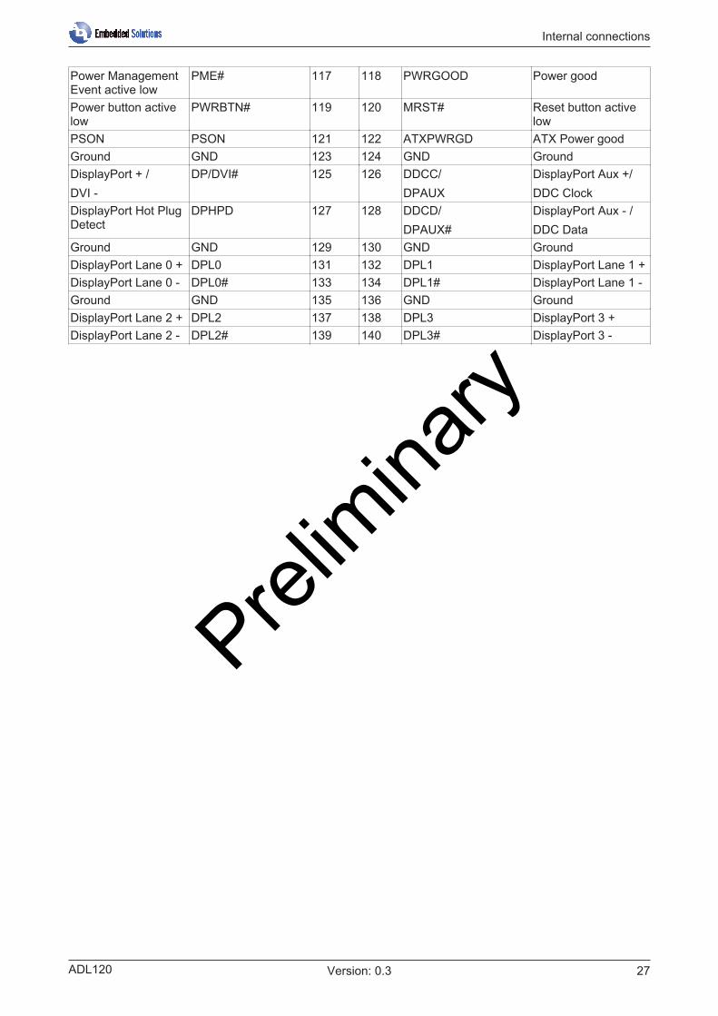
Power ManagementEvent active low
PME# 117 118 PWRGOOD Power good
Power button activelow
PWRBTN# 119 120 MRST# Reset button activelow
PSON PSON 121 122 ATXPWRGD ATX Power goodGround GND 123 124 GND GroundDisplayPort + /DVI -
DP/DVI# 125 126 DDCC/DPAUX
DisplayPort Aux +/DDC Clock
DisplayPort Hot PlugDetect
DPHPD 127 128 DDCD/DPAUX#
DisplayPort Aux - /DDC Data
Ground GND 129 130 GND GroundDisplayPort Lane 0 + DPL0 131 132 DPL1 DisplayPort Lane 1 +DisplayPort Lane 0 - DPL0# 133 134 DPL1# DisplayPort Lane 1 -Ground GND 135 136 GND GroundDisplayPort Lane 2 + DPL2 137 138 DPL3 DisplayPort 3 +DisplayPort Lane 2 - DPL2# 139 140 DPL3# DisplayPort 3 -
Prelim
inary

Internal connections
ADL12028 Version: 0.3
7.3 Internal: FANThe module has two 4-pin fan connections. This enables fans with a supply voltage of 12 V to be connecteddirectly to the module. A signal is also available for monitoring the fan speed.
Fig. 9: ADL120 FAN
Pin assignment of fan connector:
Pin Signal Description1 GND Ground2 12 V Supply voltage 12 V regulated3 TACHO Speed monitoring4 PWM Speed control
Prelim
inary

Internal connections
ADL120 29Version: 0.3
7.4 Internal: BatteryThe board is delivered with a CR2032 battery holder (Renata VBH2032-1) including a 3 V battery.
UL conformityAll technical measures for UL conformity are already integrated on the board.Accordingly, no additional actions are necessary for the connection of an RTC battery. Thebattery must be connected directly.
Fig. 10: ADL120 Bat
Synchronism of the RTCThe quartz of the RTC reacts to temperature fluctuations. Therefore, correct synchronism of theRTC is possible only with suitable and sufficient cooling!Prel
imina
ry

LEDs
ADL12030 Version: 0.3
8 LEDs
8.1 LED: Power controllerThere is an RGB LED on the board with which status messages of the power controller are output by meansof colors and flashing intervals.
Fig. 11: ADL120 PWRCTRL-LED
Color Interval MeaningNone Steadily lit System in error stateWhite Steadily lit Power failCyan Steadily lit ReservedMagenta Steadily lit S UPS active (if existent)Blue Steadily lit ReservedYellow Steadily lit S5 stateGreen Steadily lit S0 stateRed Steadily lit Reset/StartGreen/yellow Flashing Bootloader running without errorRed/yellow Flashing Bootloader is starting (start sequence is being run through)Yellow Flashing (6 s) S4 stateYellow Flashing (3 s) S3 stateMagenta Flashing (0.5 s) S UPS capacitance test (if S UPS exists)Red/magenta Flashing Checksum error during the I2C transmission in the
bootloader
A steadily lit red LED can indicate a hardware error.
Adaption of the status codesIt is possible to adapt the status codes (e.g. as TwinCAT LED) To do this, the system colors can bechanged with the aid of an SMB command. This change remains in force until the next restart or re-set. A change of the default colors is indicated by the additional flashing of the white LED.
Prelim
inary

LEDs
ADL120 31Version: 0.3
8.2 LED: SATAA further RGB LED indicates the hard disk activity.
Fig. 12: ADL120 SATA-LED
Color Interval MeaningRed Flashing Activity (access)
Prelim
inary

LEDs
ADL12032 Version: 0.3
8.3 LED: TwinCAT
Fig. 13: ADL120 TwinCAT LED
Color Interval MeaningGreen Steadily lit TwinCAT Run ModeBlue Steadily lit TwinCAT Config ModeRed Steadily lit TwinCAT Stop
Adaptation of the status codesIt is possible to adapt the status codes (e.g. as TwinCAT LED). To do this, the system colors can bechanged with the aid of an SMB command. This change remains in force until the next restart or re-set. A change of the default colors is indicated by the additional flashing of the white LED.
Prelim
inary

LEDs
ADL120 33Version: 0.3
8.4 LED: UPS-OCTThere is an RGB LED on the board with which the transmission quality of the UPS-OCT signals is indicatedby means of colors and flashing intervals.
Fig. 14: ADL120 UPS-OCT LED
Color Interval MeaningNone Steadily lit No UPS-OCT connectedBlue Flashing Bootloader activeYellow Steadily lit Moderate signal qualityGreen Steadily lit Good signal qualityRed Steadily lit Poor signal quality
If the LED does not light up, no UPS-OCT is connected.
Adaptation of the status codesIt is possible to adapt the status codes (e.g. as UPS-OCT-LED). To do this, the system colors canbe changed with the aid of an SMB command. This change remains in force until the next restart orreset. Prel
imina
ry

BIOS
ADL12034 Version: 0.3
9 BIOS
9.1 Main
Setup-Entry OptionsBoard NoneRevision NoneBios Version NoneProcessor InformationName NoneType NoneSpeed NoneID NoneStepping NoneNumber of Processors NoneMicrocode Revision NoneGT Info NoneIGFX VBIOS Version NoneIGFX GOP Version NoneMemory RC Version NoneTotal Memory NoneMemory Frequency NoneSystem Date Here the systemdate can be changed.System Time Here the systemtime can be changed.PCH Typ Q170 / H110
(depending on hardware variant:V1 → Q170V2 → H110)
Prelim
inary

BIOS
ADL120 35Version: 0.3
9.2 Advanced Menu
Setup-Entry OptionsPower-Supply Type ATX / ATSoftOff on Overheat Disabled / Enabled / Enabled (Emulate PwrBtn)Show postcode on screen Disabled / EnabledPlatform Misc Configuation Submenu see: Platform Misc Configuration [} 36]CPU Configuration Submenu see: CPU Configuration [} 37]Intel® Ethernet Connection (2) Submenu see: Intel Ethernet Connection [} 38]Driver Health Submenu see: Driver Health [} 39]Trusted Computing Submenu see: Trusted Computing [} 40]Hardware Monitor Submenu see: Hardware Monitor [} 40]PCI Subsystem Settings Submenu see: PCI Subsystem Settings [} 41]Network Stack Configuration Submenu see: Network Stack Configuration [} 42]Power Controller Options Submenu see: Power Controller Options [} 43]CSM Configuration Submenu see: CSM Configuration [} 44]NVME Configuration Submenu see: NVMe Configuration [} 45]USB Configuration Submenu see: USB Configuration [} 45]SATA and RST Configuration Submenu see: SATA und RST Configuration [} 46]AMT Configuration Submenu see: AMT Configuration [} 48]Prel
imina
ry

BIOS
ADL12036 Version: 0.3
9.3 Platform Misc Configuration
Bios-Entry OptionsPlatform Misc ConfigurationPTID Support Disabled / EnabledPECI Access Method Direct I/O / ACPINative PCIE Enable Disabled / EnabledBDAT ACPI Table Support Disabled / EnabledWake system from S5 Disabled / EnabledACPI Debug Disabled / EnabledLow Power S0 Idle Capability Disabled / EnabledLpit Recidency Counter SLP S0 / C10PCI Delay Optimization Disabled / EnabledZpODD Support Disabled / Enabled
Prelim
inary

BIOS
ADL120 37Version: 0.3
9.4 CPU Configuration
Bios-Entry OptionsCPU ConfigurationType NoneID NoneSpeed NoneL1 Data Cache NoneL1 Instruction Set NoneL2 Cache NoneL3 Cache NoneL4 Cache NoneVMX NoneSMX/TXT NoneSW Guard Extensions (SGX) Software Controllers / Enabled / DisabledCPU Flex Ratio Override Disabled / EnabledCPU Flex Ratio Settings NoneHardware Prefetcher Disabled / EnabledAdjacent Cache Line Prefetch Disabled / EnabledIntel (VMX) Virtualization Technology Disabled / EnabledPECI Disabled / EnabledActive Processor Cores All / 1 / 2 / 3Hyper-Threading Disabled / EnabledAES Disabled / EnabledIntel Trusted Execution Technology Disabled / EnabledAlias Check Request Disabled / EnabledDPR Memory Size (MB) 0..255Reset AUX Content Disabled / EnabledCPU-Power Managemant Control Submenu see: CPU Power Management Control [} 38]
Prelim
inary

BIOS
ADL12038 Version: 0.3
9.5 CPU Power Management Control
Bios-Entry OptionsCPU-Power Mangement ControlIntel® SpeedStep Disabled / EnabledIntel® Speed Shift Technology Enabled / Disabled
9.6 Intel Ethernet Connection
Bios-Entry OptionsPort ConfigurationNIC Configuration Submenu see: NIC Configuration [} 39]Blink LEDsPort Configuration InformationUEFI Driver NoneAdapter PBA NoneChip Type NonePCI DEcice ID NonePCI Address NoneLink Status NoneMAC Address None
Prelim
inary

BIOS
ADL120 39Version: 0.3
9.7 NIC Configuration
Bios-Entry OptionsLink Speed Auto Negotiated / 10 Mbps Half / 10 Mbps Full / 100 Mbps Half /
100 Mbps FullWake On LAN Disabled / Enabled
9.8 Driver Health
Bios-Entry OptionsIntel® Gigabit 0.0.16 Submenu see: Intel Gigabit [} 39]
9.9 Intel Gigabit
Bios-Entry OptionsController (xxx) None
Prelim
inary

BIOS
ADL12040 Version: 0.3
9.10 Trusted Computing
Bios-Entry OptionsConfigurationSecurity Device Support Disable / Enable
9.11 Hardware Monitor
Bios-Entry OptionsPC Health StatusCPU dig. None1.00V NoneVCCCORE None5V None12V NoneMemory VD None3.3V NoneFan 1 NoneFan 2 NoneMB Temp NoneMemory Temp NonePwCtrlTemp None
Prelim
inary

BIOS
ADL120 41Version: 0.3
9.12 PCI Subsystem Settings
Bios-Entry OptionsPCI Bus Driver Version NonePCI Device Common Settings:PCI Latency Timer 32 / 64 / 96 / 128 / 160 /192 / 224 / 248 / PCI Bus ClocksPCI-X Latency Timer 32 / 64 / 96 / 128 / 160 /192 / 224 / 248 / PCI Bus ClocksVGA Palette Snoop Disabled / EnabledPERR# Generation Disabled / EnabledSERR# Generation Disabled / EnabledAbove 4G Decoding Disabled / EnabledPCI Hot-Plug Settings Submenu see: PCI Hot-Plug Settings [} 41]
9.13 PCI Hot-Plug Settings
Bios-Entry OptionsPCI Hot-Plug SettingsBIOS Hot-Plug Support Enabled / DisabledPCI Buses Padding Disabled / 1 / 2 / 3 / 4 / 5I/O Resources Padding Disabled / 4 K / 8 K / 16 K / 32 KMMIO 32 bit Resources Padding Disabled / 1 M / 2 M / 4 M / 8 M / 16 M / 32 M / 64 M / 128 MPFMMIO 32 bit Resources Padding Disabled / 1 M / 2 M / 4 M / 8 M / 16 M / 32 M / 64 M / 128 M
Prelim
inary

BIOS
ADL12042 Version: 0.3
9.14 Network Stack Configuration
Bios-Entry OptionsNetwork Stack Disabled / EnabledIpv4 PXE Support Disabled / EnabledIpv4 http Support Disabled / EnabledIpv6 PXE Support Disabled / EnabledIPV6 http Support Disabled / EnabledIP6 Configuration Automatic / ManualPXE boot wait time 0..5Media detect count 0..50
Prelim
inary
BIOS
ADL120 43Version: 0.3
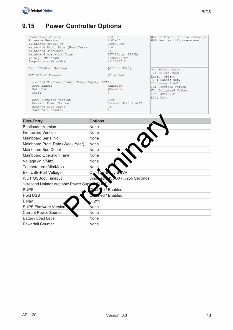
9.15 Power Controller Options
Bios-Entry OptionsBootloader Version NoneFirmaware Version NoneMainboard Serial No NoneMainboard Prod. Date (Week.Year) NoneMainboard BootCount NoneMainboard Operation Time NoneVoltage /Min/Max) NoneTemperature (Min/Max) NoneExt. USB-Port Voltage Off in S3-5 / by SCVVWDT OSBoot Timeout Disabled / 45 / 60 / ../255 Seconds1-second Uninteruruptable Power Supply (SUPS)SUPS Disabled / EnabledHold USB Disabled / EnabledDelay 0..255SUPS Firmware Version NoneCurrent Power Source NoneBattery Load Level NonePowerfail Counter None
Prelim
inary

BIOS
ADL12044 Version: 0.3
9.16 CSM Configuration
Bios-Entry OptionsCompatibility Support Module ConfigurationCSM Support Enabled / DisabledCSM16 Module Version NoneGateA20 Active Upon Request / AlwaysOption ROM Messages Force BIOS / Keep CurrentINT19 Trap Response Immediate / PostponedBoot option filter UEFI and Legacy / Legacy only / UEFI onlyOption ROM executionNetwork Do not launch / UEFI / LegacyStorage Do not launch / UEFI / LegacyVideo Do not launch / UEFI / LegacyOther PCI devices Do not launch / UEFI / Legacy
Prelim
inary

BIOS
ADL120 45Version: 0.3
9.17 NVMe Configuration
Bios-Entry OptionsNVMe controller and Drive Information[Device list] None
NOTENVMe Raid 0/1 is not supported.
9.18 USB Configuration
Bios-Entry OptionsUSB ConfigurationUSB Module Version NoneUSB Controllers NoneUSB Devices NoneLegacy USB Support Enabled / Disabled / AutoXHCI Hand-off Enabled / DisabledUSB Mass Storage Driver Support Enabled / DisabledPort 60/64 Emulation Disabled / EnabledUSB hardware delays and time-outsUSB transfer time-out 1 / 5 / 10 / 20 secDevice reset time-out 10 / 20 / 30 / 40 secDevice power-up delay Auto/ Manual
Prelim
inary

BIOS
ADL12046 Version: 0.3
9.19 SATA und RST Configuration
Bios-Entry OptionsSATA And RST ConfigurationSATA Controller(s) Enabled / DisabledSATA Mode Selection AHCI / Intel RST PremiumSATA Test Mode Enabled / DisabledRAID Device ID Client / AlternateSoftware Feature Mask Configuration Submenu see: Software Feature Mask Configuration [} 47]Aggressive LPM Support Disabled / EnabledSATA Controller Speed Default / Gen1 / Gen2 / Gen3Serial ATA Port X NoneSoftware Preserve NonePort X Disabled / EnabledHot Plug Disabled / EnabledCinfigured as eSATA NoneSpin Up Device Disabled / EnabledTopology Unknown / ISATA / Direct Connect / FLEX / M2SATA Port X Dev Slp Disabled / EnabledDITO Configuration Disabled / Enabled
Prelim
inary

BIOS
ADL120 47Version: 0.3
9.20 Software Feature Mask Configuration
Bios-Entry OptionsSoftware Feature Mask ConfigurationeHDD Unlock Disabled / EnabledLED Locate Disabled / EnabledRAID0 Enabled / DisabledRAID1 Enabled / DisabledRAID10 Enabled / DisabledRaid5 Enabled / DisabledIntel Rapid Recovery Technology Enabled / DisabledOROM UI and BANNER Enabled / DisabledIRRT Only on eSATA Enabled / DisabledSmart Response Technology Enabled / DisabledOROM UI Normal Delay 2 secs / 4 secs / 6 secs / 8 secsRTS Force Form Enabled / Disabled
Prelim
inary

BIOS
ADL12048 Version: 0.3
9.21 AMT Configuration
Bios-Entry OptionsASF Support Disabled / EnabledUSB Provisioning of AMT Disabled / EnabledCIRA Configuration Untermenü siehe : CIRA Configuration [} 48]ASF Configuration Untermenü siehe: ASF Configuration [} 49]Secure Erase Configuration Untermenü siehe: Secure Erase Configuration [} 49]OEM Flags Settings Untermenü siehe: OEM Flags Settings [} 50]MEBx Resolution Settings Untermenü siehe: MEBx Resolution Settings [} 51]
9.22 CIRA Configuration
Bios-Entry OptionsActivate Remote Assistance Process Disabled / EnabledCIRA Timeout 0..255
Prelim
inary

BIOS
ADL120 49Version: 0.3
9.23 ASF Configuration
Bios-Entry OptionsPEt Progress Disabled / EnabledWatchDog Disabled / EnabledOS Timer 0..65535BIOS Timer 0..65535
9.24 Secure Erase Configuration
Bios-Entry OptionsSecure Erase Mode Simulated / RealForce Secure Erase Disabled / EnabledPrel
imina
ry

BIOS
ADL12050 Version: 0.3
9.25 OEM Flags Settings
Bios-Entry OptionsMBEx hotkey pressed Disabled / EnabledMBEx Selection Screen Disabled / EnabledHide Unconfigure ME ConfirmationPrompt
Disabled / Enabled
MBEx OEM Debug Menu Enable Disabled / EnabledUnconfigure ME Disabled / Enabled
Prelim
inary

BIOS
ADL120 51Version: 0.3
9.26 MEBx Resolution Settings
Bios-Entry OptionsNon-UI Resolution Auto / 80x25 / 100x31UI Mode Resolution Auto / 80x25 / 100 x 31Graphics Mode Resolution Auto / 640x 480 / 800x600 / 1024 x 768
9.27 Chipset
Setup-Entry OptionsSystem Agent (SA) Configuration Submenu see: System Agent (SA) Configuration
[} 52]PCH-IO Configuration Submenu see: PCH-IO Configuration [} 55]Prel
imina
ry

BIOS
ADL12052 Version: 0.3
9.28 System Agent (SA) Configuration
Bios-Entry OptionsSystem Agent (SA) ConfigurationSA PCIe Code Version NoneVT-d NoneGraphics Configuration Submenu see: Graphics Configuration [} 53](PEG-Port X assignemt) NoneVT-d Disabled / EnabledChap Device Disabled / EnabledThermal Device Disabled / EnabledGMM Device Disabled / EnabledCRID Support Disabled / Enabled
Prelim
inary

BIOS
ADL120 53Version: 0.3
9.29 Graphics Configuration
Bios-Entry OptionsGraphics ConfigurationSkip Scanning of External Gfx Card Disabled / EnabledPrimary Display Auto / IGFX / PEG / PCI / SGSelect PCIE Card Auto / Elk Creek 4 / PEG EvalExternal Gfx Card Primary DisplayConfiguration
Submenu see: External Gfx Card Primary Display Configuration[} 54]
Internal Graphics Auto / Disabled / EnabledGTT Size 2 MB / 4 MB / 8 MBAperture Size 128MB /256MB / 512MB / 1024MB / 2048MBDVMT Pre-allocated 32M / 64M / 4M / 8m / 12M / 16M / 20M / 24M / 28M / 32M / 36M /
40M / .. / 60MDVMT Total Gfx Mem 256M / 128M / MAXGfx Low Power Mode Enabled / DisabledVDD Enable Enabled / DisabledHDCP Support Enabled / DisabledAlgorithm One-time / PeriodicPM Support Enabled / DisabledSet Power Clamp Disabled / EnabledPAVP Enable Enabled / DisabledCdynmax Clamping Enable Enabled / DisabledCd Clock Frequency 337.5 Mhz / 450 Mhz / 540 Mhz / 675 MhzIUER Button Enable Disabled / EnabledLCD Control Submenu see: LCD Control [} 54]
Prelim
inary

BIOS
ADL12054 Version: 0.3
9.30 External Gfx Card Primary Display Configuration
Bios-Entry OptionsExternal Gfx Card Primary DisplayConfigurationPrimary PEG Auto / PEG11 /PEG12Primary PCIE Auto / PCIE1 / PCIE2 / PCIE3 / … / PCIE19
9.31 LCD Control
Bios-Entry OptionsLCD ControlPrimary IGFX VBIOS Default / EFP (/ EFP2 / EFP3LCD Panel Type VBIOS Default / 640x480 LVDS / 800x600 LVDS / 1024x768 LVDS /
1280x1024 LVDS / 1400x1050 LVDS1 / 1400x1050 LVDS2 /1600x1200 LVDS / 1280x768 LVDS / 1680x1050 LVDS / 1920x1200LVDS / 1600x900 LVDS / 1280x800 LVDS / 1280x600 LVDS /2048x1536 LVDS / 1366x768 LVDS
Panel Scaling Auto / Off / Force ScalingBacklight Control PWM Inverted / PWM NormalActive LFP Noe DP / eDP Port-APanel Color Depth 18 Bit / 24 BitBacklight Brightness 0..255
Prelim
inary

BIOS
ADL120 55Version: 0.3
9.32 PCH-IO Configuration
Bios-Entry OptionsPCH-IO ConfigurationPCI Express Configuration Submenu see: PCI Express Configuration [} 56]USB Configuration Submenu see: USB Configuration [} 58]HD Audio Configuration Submenu see: HD Audio Configuration [} 59]PCH LAN Controller Enabled / Disabled bei V1, always Enabled bei V2Wake on LAN Enabled / DisabledSecond LAN Controller Enabled / DisabledThird LAN Controller Enabled / DisabledForth LAN Controller Enabled / DisabledM.2-Slot X NoneCLKRUN#logic Enabled / DisabledState After G3 S0 State / S5 StateCompatible Revision ID Enabled / Disabled
Prelim
inary
BIOS
ADL12056 Version: 0.3
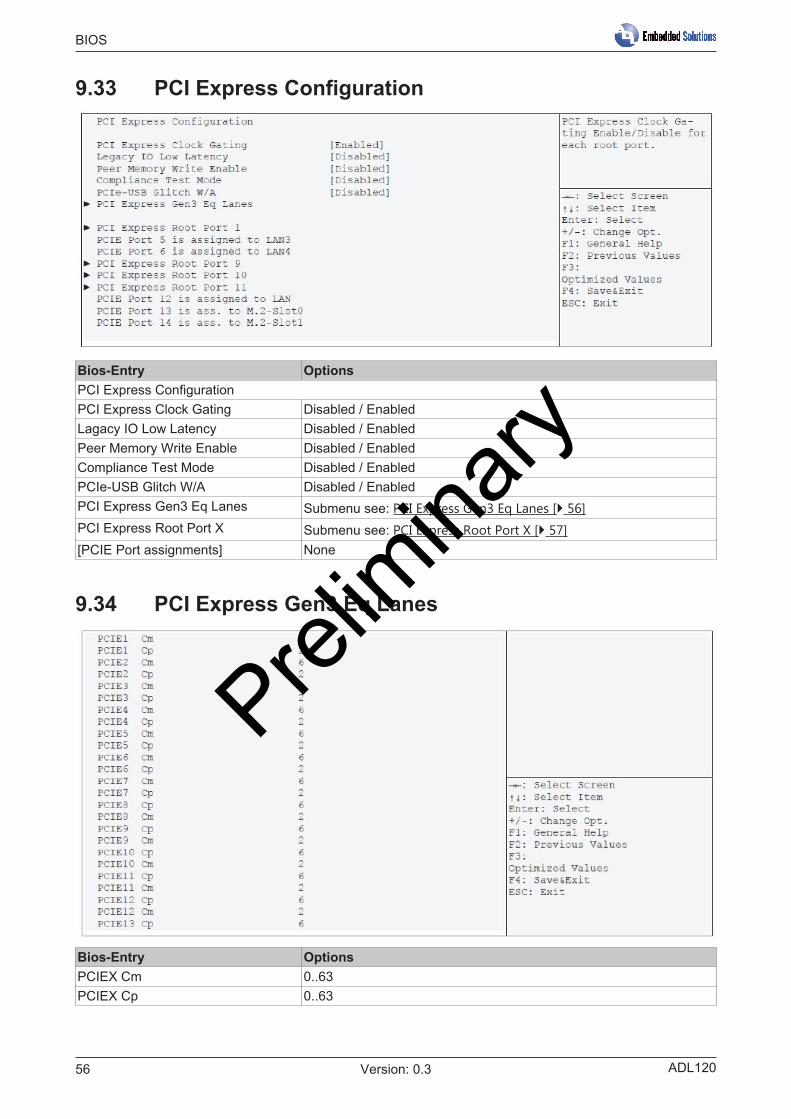
9.33 PCI Express Configuration
Bios-Entry OptionsPCI Express ConfigurationPCI Express Clock Gating Disabled / EnabledLagacy IO Low Latency Disabled / EnabledPeer Memory Write Enable Disabled / EnabledCompliance Test Mode Disabled / EnabledPCIe-USB Glitch W/A Disabled / EnabledPCI Express Gen3 Eq Lanes Submenu see: PCI Express Gen3 Eq Lanes [} 56]PCI Express Root Port X Submenu see: PCI Express Root Port X [} 57][PCIE Port assignments] None
9.34 PCI Express Gen3 Eq Lanes
Bios-Entry OptionsPCIEX Cm 0..63PCIEX Cp 0..63
Prelim
inary

BIOS
ADL120 57Version: 0.3
9.35 PCI Express Root Port X
Bios-Entry OptionsPCI Express Root Port 1 Disabled / EnabledTopolgy Unknown / x1 / x4 / Sata Express / M2ASPM L0sL1 / L1 L0s / Disabled / AutoL1 Substates Disabled / L1.1 & L1.2 / L1.1 / L1.2Gen3 Eq Phase3 Method Hardware / Static Coeff. / Software SearchUDTP 0..10DPTP 0..10ACS Disabled / EnabledURR Disabled / EnabledFER Disabled / EnabledNFER Disabled / EnabledCER Disabled / EnabledCTO Disabled / EnabledSEFE Disabled / EnabledSENFE Disabled / EnabledSECE Disabled / EnabledPME SCI Disabled / EnabledHot Plug Disabled / EnabledAdvanced Error Reporting Disabled / EnabledPCIe Speed Auto / Gen1 / Gen2 / Gen3Transmitter Half Swing Disabled / EnabledDetect Timeout 0..65535Extra Bus Reserved 0..7Reserved I/O 4K / 8K / 12K / 16K / 20KPCH PCIe LTR ConfigurationPCH PCIE1 LTR Disabled / EnabledSnoop Latency Override Disabled / Manual / AutoSnoop Latency Value 0..1023Snoop Latency Multipler 1 ns / 32 ns / 1024 ns / 32768 ns / 1048576 ns / 33554432 nsNon Snoop Latency Override Disabled / Manual / Auto
Prelim
inary

BIOS
ADL12058 Version: 0.3
9.36 Extra Options
Bios-Entry OptionsDetect Non-Compliance Device Disabled / EnabledPrefetchable Memory 1..20Reserved Memory Alignment 1..31Prefetchable Menmory Alignment 1..31
9.37 USB Configuration
Bios-Entry OptionsUSB ConfigurationXHCI Diable Comliance Mode False / TrueUSB Port Disable Override Disabled / Select Per-PinUSB SS Physical Connector #X Disabled / Enabled
Prelim
inary

BIOS
ADL120 59Version: 0.3
9.38 HD Audio Configuration
Bios-Entry OptionsHD Audio System Configuration SettingsHD Audio Disabled / Enabled / Auto
9.39 Security
Setup-Entry OptionsPassword DescriptionMinimum length NoneMaximum length NoneAdministrator Password Here an administrator password can be set.User Mode Enabled / DisabledSecure Boot Submenu see: Secure Boot [} 60]
Prelim
inary

BIOS
ADL12060 Version: 0.3
9.40 Secure Boot
Bios-Entry OptionsSystem Mode NoneSecure Boot NoneVendor Keys NoneAttempt Secure Boot Disabled / EnabledSecure Boot Mode Standard / CustomKey Management Submenu see: Key Management [} 60]
9.41 Key Management
Bios-Entry OptionsProvision Factory Defaults Disabled / EnabledReset to Setup Mode Press entry keyEnroll Efi Image Press entry keySave all Secure Boot variables Press entry keyPlatformKey(PK) Press entry keyKey Exchange Keys Press entry keyAuthorized Signatures Press entry keyForbidden Signatures Press entry keyAuthorized TimeStamps Press entry keyOsRecovery Signatures Press entry key
Prelim
inary

BIOS
ADL120 61Version: 0.3
9.42 Boot
Bios-Entry OptionsBoot ConfigurationSetup Prompt Timeout 0..65535Bootup NumLok State On / OffF7 Boot Menu Disabled / EnabledFull Screen Logo Disabled / EnabledFast Boot Disabled / EnabledNew Boot Option Policy Default / Place First / Place LastStartUpDElay for UEFI shell 0..255Boot mode select Legacy / UEFI / DualFixed Boot Order PrioritiesBoot Option #1-19 Here the range of boot media to be used can be set.Advanced Fixed Boot OrderParameters
Submenu see: Fixed Boot Order Parameters [} 62]
Prelim
inary

BIOS
ADL12062 Version: 0.3
9.43 Fixed Boot Order Parameters
Bios-Entry OptionsMax. CFast/SSD capacity 1..16384Max. USB Stick capacity (GB) 1..16384
9.44 Save & Exit
Bios-Entry OptionsSave Changes and ResetDiscard Changes and Reset Press entry keyRestore Optimized Defaults Press entry keyBoot OverrideIBA CL slot 00FE v0110 Press entry keyLaunch EFI Shell from filesystemdevice
Press entry key
Prelim
inary

Mechanical drawings
ADL120 63Version: 0.3
10 Mechanical drawingsDimensional notationAll dimensions are in mil (1 mil = 0.0254 mm). Data in square brackets are in mm.
10.1 PCB: Holes
Fig. 15: MZ MH ADL120
Prelim
inary

Mechanical drawings
ADL12064 Version: 0.3
10.2 PCB: Pin 1 distances
Fig. 16: MZ Pin1 ADL120 Prelim
inary

Mechanical drawings
ADL120 65Version: 0.3
10.3 PCB: Dimensions
Fig. 17: MZ ADL120
Prelim
inary

Technical data
ADL12066 Version: 0.3
11 Technical data
11.1 Electrical dataPower supplyBoard 24 V (+/- 5%)RTC >= 3 µm
Power consumptionRTC <= 10 µm
11.2 Environmental conditionsTemperature rangeOperating 0 °C up to +60 °C (more extended temperture range
on request)Storage -25 °C up to +85 °CDispatch -25 °C up to +85 °C, for wrapped boards
Temperature changesOperating 0.5 °C per minute, 7.5 °C in 30 minutesStorage 1.0 °C per minuteDispatch 1.0 °C per minute, for wrapped boards
Relative air humidityOperating 5% up to 85% (non-condensing)Storage 5% up to 95% (non-condensingDispatch 5% up to 100% (non-condesing), for wrapped boards
ImpactOperating 150 m/², 6 msStorage 400 m/s², 6 msDispatch 400 m/s², 6 ms, for wrapped boards
VibrationOperating 10 up to 58 Hz, 0.075 mm amplitudeStorage 5 up to 9 Hz, 3.5 mm amplitude
9 up to 500 Hz, 10 m/s²Dispatch 5 up to 9 Hz, 3.5 mm amplitude
9 up to 500 Hz, 10 m/s², for wrapped boards
Note on impact and vibration resistanceThe specifications for impact and vibration resistance refer only to the motherboard itself withoutheat sink, memory module, cabling, etc.
Prelim
inary

Technical data
ADL120 67Version: 0.3
11.3 Technical specificationsThe board is specified for an ambient temperature range of 0 °C to +60 °C (extended temperature range onenquiry). In addition, care must be taken that the temperature of the processor die does not exceed 100 °C.A suitable cooling concept must be implemented for this that is oriented to the maximum power consumptionof the processor/chipset. Please note: also that any existing controllers are included in the cooling concept.The power consumption of these modules may be of the same order of magnitude as the powerconsumption of the processor.
The board is prepared with suitable holes for the use of modern cooling solutions. We have a series ofcompatible cooling components in our range. Your distributor will be glad to advise you on choosing suitablesolutions.
NOTEPrevent the maximum die temperature being exceeded!It is the end customer's responsibility to ensure that the die temperature of the processor does not exceed100 °C! Continuous overheating can destroy the board!If the temperature exceeds 100 °C, the ambient temperature needs to be reduced. Ensure sufficient air cir-culation if necessary.
Prelim
inary

Support
ADL12068 Version: 0.3
12 Support
12.1 Technical SupportTechnical support for this product can be obtained in the following ways:
• By contacting our support staff at +1 858-490-0597 or +49 (0) 271 250 810 0• By contacting our staff via e-mail at [email protected] or [email protected]• Via our website at www.adl-usa.com/support or www.adl-europe.com/support
Prelim
inary

Appendix I: Post Codes
ADL120 69Version: 0.3
13 Appendix I: Post CodesDuring the boot phase, the BIOS generates a series of status messages (so-called "POST Codes"), whichcan be output with the help of a suitable reading device (POST Code card). The meanings of the POSTCodes are explained in the document "Aptio™ 5.x Status Codes" from American Megatrends®, which isavailable from the website http://www.ami.com. In addition, the following OEM POST Codes are output:
Code Description87h BIOS-API started88h PCA9535 started89h PWRCTRL firmware started
Prelim
inary

Appendix II: Resources
ADL12070 Version: 0.3
14 Appendix II: Resources
14.1 InterruptThe resources used are independent of the setup setting. The listed interrupts and their use are given by theAT compatibility. If interrupts have to be exclusively available on the ISA side, they must be reserved throughthe BIOS setup. Exclusivity is neither given nor possible on the PCI side.
Address FunctionIRQ0 TimerIRQ1IRQ2IRQ3IRQ4IRQ5IRQ6IRQ7IRQ8 RTCIRQ9IRQ10IRQ11IRQ12IRQ13 FPUIRQ14IRQ15
Prelim
inary

Appendix II: Resources
ADL120 71Version: 0.3
14.2 PCI DevicesThe PCI devices listed here all exist on the board, including those that are detected and configured by theBIOS. Due to the BIOS setup settings it may be the case that various PCI devices or functions of devices arenot activated. If devices are deactivated, the bus numbers of other devices may change as a result.
INT REQ Bus Dev. Fct. Controller / Slot- - 0 0 0 Host Bridge ID 191F
- 0 1 0 PCI Bridge (0-1) x1(x16) ID1901A - 0 2 0 VGA Controller ID1912A - 0 08 0 System Peripheral ID1911A - 0 20 0 XHCI Controller IDA12FA - 0 20 2 Other DPIO Module ID1311A - 0 22 0 Serial Other IDA13AA - 0 23 0 SATA (AHCI 1.0) IDA102A - 0 28 0 PCI Bridge (0-2) x1 (x1) IDA114B - 0 28 0 PCI Bridge (0-3) x1 (x1) IDA115
- 0 31 0 ISA Bridge IDA143- 0 31 2 Memory Controller IDA121- 0 31 4 SMBus Controller IDA123
B - 0 31 6 Ethernet Controller ID15B7A - 1 00 0 Ethernet Controller x1 (x1) ID1531
2 00 0 Ethernet Controller x1 (x1) ID15313 00 0 Ethernet Controller x1 (x1) ID1531
Prelim
inary

Appendix II: Resources
ADL12072 Version: 0.3
14.3 SMB-DevicesThe following table lists the reserved SM-Bus device addresses in 8-bit notation.
NOTEThese address ranges may not be used by external devices even if the component assigned in the tabledoesn't exist on the motherboard.
Address Function34-35 API access to power supply unit36-39 Reserved5C-5D NCT749160-6F Reserved for DDR470-73 POST Code output88-89 Slave address defined by BIOS92-93 I210 defaultA0-A7 Reserved for DDR4B0-B3 Power controller (access via BIOS-API)B8-BB Power controller (access via BIOS-API)
Prelim
inary
Related Documents