Hercules U26 Návod k obsluze VIADRUS G 350 MANUAL FOR BOILER OPERATION AND INSTALLATION

Welcome message from author
This document is posted to help you gain knowledge. Please leave a comment to let me know what you think about it! Share it to your friends and learn new things together.
Transcript
Hercules U26Návod k obsluze
VIADRUS G 350MANUAL FOR BOILER OPERATION
AND INSTALLATION
2
Table of contents: page
1. Boiler use and advantages ...................................................................................................................... 3
2. Boiler technical data ................................................................................................................................ 4
3. Description ............................................................................................................................................... 6
3.1 Boiler construction .............................................................................................................................. 6
4. Positioning and installation ...................................................................................................................... 8
4.1 Boiler standing in boiler room ............................................................................................................. 8
4.2 Directives and regulations .................................................................................................................. 9
5. Order, delivery and assembly ................................................................................................................ 11
5.1 Order ................................................................................................................................................ 11
5.2 Delivery and accessories ................................................................................................................. 11
5.3 Assembly process ............................................................................................................................ 11
5.3.1 Installation of the boiler body ...................................................................................................... 11
5.3.2 Pressuring the boiler body .......................................................................................................... 12
5.3.3 Installation of the burner plate ..................................................................................................... 13
5.3.4 Mounting of closing plate ............................................................................................................ 13
5.3.5 Installation of flue throat .............................................................................................................. 14
5.3.6 Installation of valves .................................................................................................................... 14
5.3.7 Installation of shell ....................................................................................................................... 15
6. Commissioning ...................................................................................................................................... 16
6.1 Checking activities before initiation .................................................................................................. 16
6.2 Boiler conversion from „liquid fuels“ to „ gas fuels“ and back .......................................................... 16
7. Boiler operation by user ........................................................................................................................ 17
7.1 Electric panel – basic design ............................................................................................................ 17
8. IMPORTANT WARNINGS .................................................................................................................... 18
9. Maintenance .......................................................................................................................................... 19
10. Instructions for product disposal after its service life ............................................................................. 19
11. Failures and their elimination ................................................................................................................ 19
12. Guarantee and liability for defects ......................................................................................................... 20
3
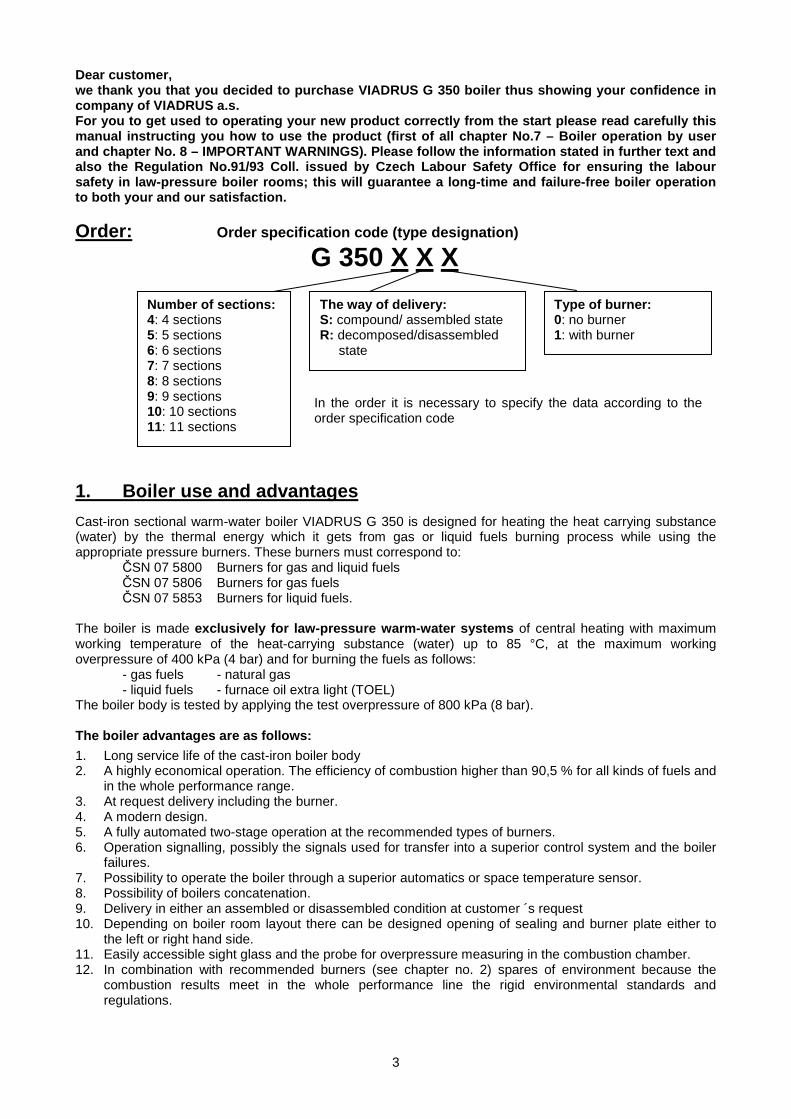
Dear customer, we thank you that you decided to purchase VIADRUS G 350 boiler thus showing your confidence in company of VIADRUS a.s. For you to get used to operating your new product correctly from the start please read carefully this manual instructing you how to use the product (first of all chapter No.7 – Boiler operation by user and chapter No. 8 – IMPORTANT WARNINGS). Please follow the information stated in further text and also the Regulation No.91/93 Coll. issued by Czech Labour Safety Office for ensuring the labour safety in law-pressure boiler rooms; this will guarantee a long-time and failure-free boiler operation to both your and our satisfaction.
Order: Order specification code (type designation)
G 350 X X X
1. Boiler use and advantages
Cast-iron sectional warm-water boiler VIADRUS G 350 is designed for heating the heat carrying substance (water) by the thermal energy which it gets from gas or liquid fuels burning process while using the appropriate pressure burners. These burners must correspond to:
ČSN 07 5800 Burners for gas and liquid fuels ČSN 07 5806 Burners for gas fuels ČSN 07 5853 Burners for liquid fuels.
The boiler is made exclusively for law-pressure warm-water systems of central heating with maximum working temperature of the heat-carrying substance (water) up to 85 °C, at the maximum working overpressure of 400 kPa (4 bar) and for burning the fuels as follows: - gas fuels - natural gas
- liquid fuels - furnace oil extra light (TOEL) The boiler body is tested by applying the test overpressure of 800 kPa (8 bar). The boiler advantages are as follows:
1. Long service life of the cast-iron boiler body 2. A highly economical operation. The efficiency of combustion higher than 90,5 % for all kinds of fuels and
in the whole performance range. 3. At request delivery including the burner. 4. A modern design. 5. A fully automated two-stage operation at the recommended types of burners. 6. Operation signalling, possibly the signals used for transfer into a superior control system and the boiler
failures. 7. Possibility to operate the boiler through a superior automatics or space temperature sensor. 8. Possibility of boilers concatenation. 9. Delivery in either an assembled or disassembled condition at customer ´s request 10. Depending on boiler room layout there can be designed opening of sealing and burner plate either to
the left or right hand side. 11. Easily accessible sight glass and the probe for overpressure measuring in the combustion chamber. 12. In combination with recommended burners (see chapter no. 2) spares of environment because the
combustion results meet in the whole performance line the rigid environmental standards and regulations.
The way of del ivery: S: compound/ assembled state R: decomposed/disassembled
state
Number of sections : 4: 4 sections 5: 5 sections 6: 6 sections 7: 7 sections 8: 8 sections 9: 9 sections 10: 10 sections 11: 11 sections
Type of burner: 0: no burner 1: with burner
In the order it is necessary to specify the data according to the order specification code
4
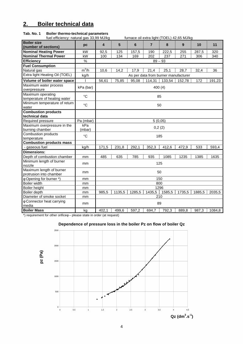
2. Boiler technical data Tab. No. 1 Boiler thermo-technical parameters fuel efficiency: natural gas 33,99 MJ/kg furnace oil extra light (TOEL) 42,65 MJ/kg Boiler size (number of sections) pc 4 5 6 7 8 9 10 11
Nominal Heating Power kW 92,5 125 157,5 190 222,5 255 287,5 320 Nominal Thermal Power kW 100 134 169 202 237 271 306 340 Efficiency % 89 – 93 Fuel Consumpt ion Natural gas m3/h 10,6 14,2 17,9 21,4 25,1 28,7 32,4 36 Extra light Heating Oil (TOEL) kg/h As per data from burner manufacturer Volume of boiler water space l 56,61 75,85 95,08 114,31 133,54 152,78 172 191,23 Maximum water process overpressure kPa (bar) 400 (4)
Maximum operating temperature of heating water °C 85
Minimum temperature of return water °C 50
Combustion products technical data
Required pressure Pa (mbar) 5 (0,05) Maximum overpressure in the burning chamber
kPa (mbar) 0,2 (2)
Combustion products temperature
°C 185
Combustion products mass - gaseous fuel kg/h 171,5 231,8 292,1 352,3 412,6 472,9 533 593,4 Dimensions: Depth of combustion chamber mm 485 635 785 935 1085 1235 1385 1635 Minimum length of burner nozzle mm 125
Maximum length of burner protrusion into chamber mm 50
φ Opening for burner *) mm 150 Boiler width mm 800 Boiler height mm 1296 Boiler depth mm 985,5 1135,5 1285,5 1435,5 1585,5 1735,5 1885,5 2035,5 Diameter of smoke socket mm 210 φ Connector heat carrying media
mm 89
Boiler Mass kg 402,1 499,6 597,2 694,7 792,3 889,8 987,3 1084,8 *) requirement for other orificeφ – please state in order (at request)
Dependence of pressure loss in the boiler Pz on flow of boiler Qz
0
500
1000
1500
2000
2500
0 0,5 1 1,5 2 2,5 3 3,5 4 4,5
Qz (dm 3.s-1)
pz (
Pa)
5
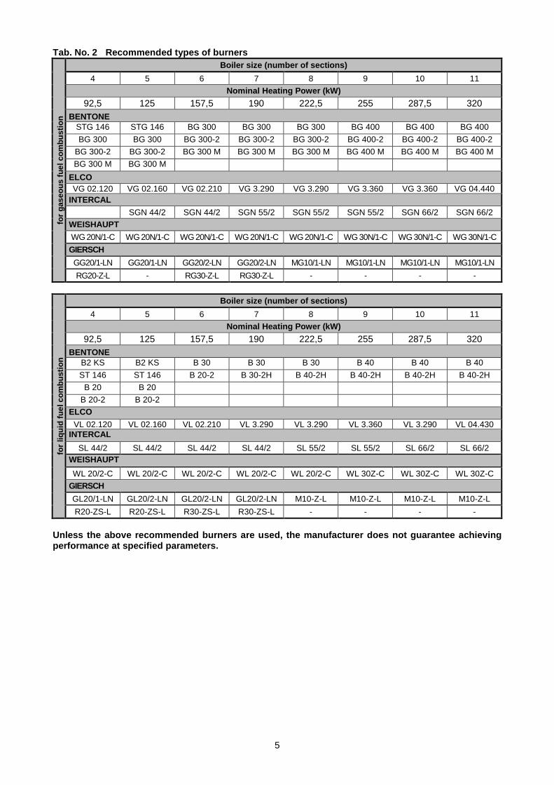
Tab. No. 2 Recommended types of burners fo
r ga
seou
s fu
el c
ombu
stio
n Boiler size (number of sections)
4 5 6 7 8 9 10 11
Nominal Heating Power (kW)
92,5 125 157,5 190 222,5 255 287,5 320 BENTONE
STG 146 STG 146 BG 300 BG 300 BG 300 BG 400 BG 400 BG 400
BG 300 BG 300 BG 300-2 BG 300-2 BG 300-2 BG 400-2 BG 400-2 BG 400-2
BG 300-2 BG 300-2 BG 300 M BG 300 M BG 300 M BG 400 M BG 400 M BG 400 M
BG 300 M BG 300 M ELCO VG 02.120 VG 02.160 VG 02.210 VG 3.290 VG 3.290 VG 3.360 VG 3.360 VG 04.440
INTERCAL
SGN 44/2 SGN 44/2 SGN 55/2 SGN 55/2 SGN 55/2 SGN 66/2 SGN 66/2 WEISHAUPT
WG 20N/1-C WG 20N/1-C WG 20N/1-C WG 20N/1-C WG 20N/1-C WG 30N/1-C WG 30N/1-C WG 30N/1-C
GIERSCH
GG20/1-LN GG20/1-LN GG20/2-LN GG20/2-LN MG10/1-LN MG10/1-LN MG10/1-LN MG10/1-LN
RG20-Z-L - RG30-Z-L RG30-Z-L - - - -
for
liqui
d fu
el c
ombu
stio
n
Boiler size (number of sections)
4 5 6 7 8 9 10 11
Nominal Heating Power (kW)
92,5 125 157,5 190 222,5 255 287,5 320 BENTONE
B2 KS B2 KS B 30 B 30 B 30 B 40 B 40 B 40
ST 146 ST 146 B 20-2 B 30-2H B 40-2H B 40-2H B 40-2H B 40-2H
B 20 B 20
B 20-2 B 20-2 ELCO
VL 02.120 VL 02.160 VL 02.210 VL 3.290 VL 3.290 VL 3.360 VL 3.290 VL 04.430 INTERCAL
SL 44/2 SL 44/2 SL 44/2 SL 44/2 SL 55/2 SL 55/2 SL 66/2 SL 66/2 WEISHAUPT
WL 20/2-C WL 20/2-C WL 20/2-C WL 20/2-C WL 20/2-C WL 30Z-C WL 30Z-C WL 30Z-C
GIERSCH
GL20/1-LN GL20/2-LN GL20/2-LN GL20/2-LN M10-Z-L M10-Z-L M10-Z-L M10-Z-L
R20-ZS-L R20-ZS-L R30-ZS-L R30-ZS-L - - - -
Unless the above recommended burners are used, the manufacturer does not guarantee achieving performance at specified parameters.

6
3. Description 3.1 Boiler construction
The boiler body consists of sections assembled by means of forced-on insertions and is secured by anchor bolts. Boiler has a three-draught construction and the sections create the combustion space and the convection part, inside then the boiler water space. The tightness of boiler gas combustion space is guaranteed by boiler cement applied to sections seating faces and to circumference of individual section joints. On the front section there are fixed sealing and burner plates that either can be opened to right or left hand side according to boiler room layout. This must correspond with screw suspensions positioning (lugs). The openings G 2"in the front section are closed with plugs G 2". The upper plug has a boring G 1/2“ for the basin of regulation and safety thermostat. In the left upper riser of the section there are two openings G 1/2" for thermometer and pressure gauge sensors. The input and output of a heat carrying substance is situated at the rear part of boiler and it is carried out with flanges and a mouthpiece DN 80. At the lower flange with a mouthpiece there is positioned the filling & discharging cock. In the opening for inlet of heat transfer fluid (under the flange) there is installed the distribution pipe, which directs the flow of water in the boiler. The combustion gases from the boiler are led/ taken away through a flue orifice with an explosion shutter which at the same time serves as a small cleaning cover. At the flue orifice there are measuring points for temperature and combustion gases analysis. The boiler body is fully insulated by plates made of mineral insulation. The steel shell of boiler is surface treated by comaxite paint. In the upper front part of boiler there is positioned the electro-panel with regulation, safety and control elements.
Fig. no. 1 Main dimensions of boiler
(L)
7
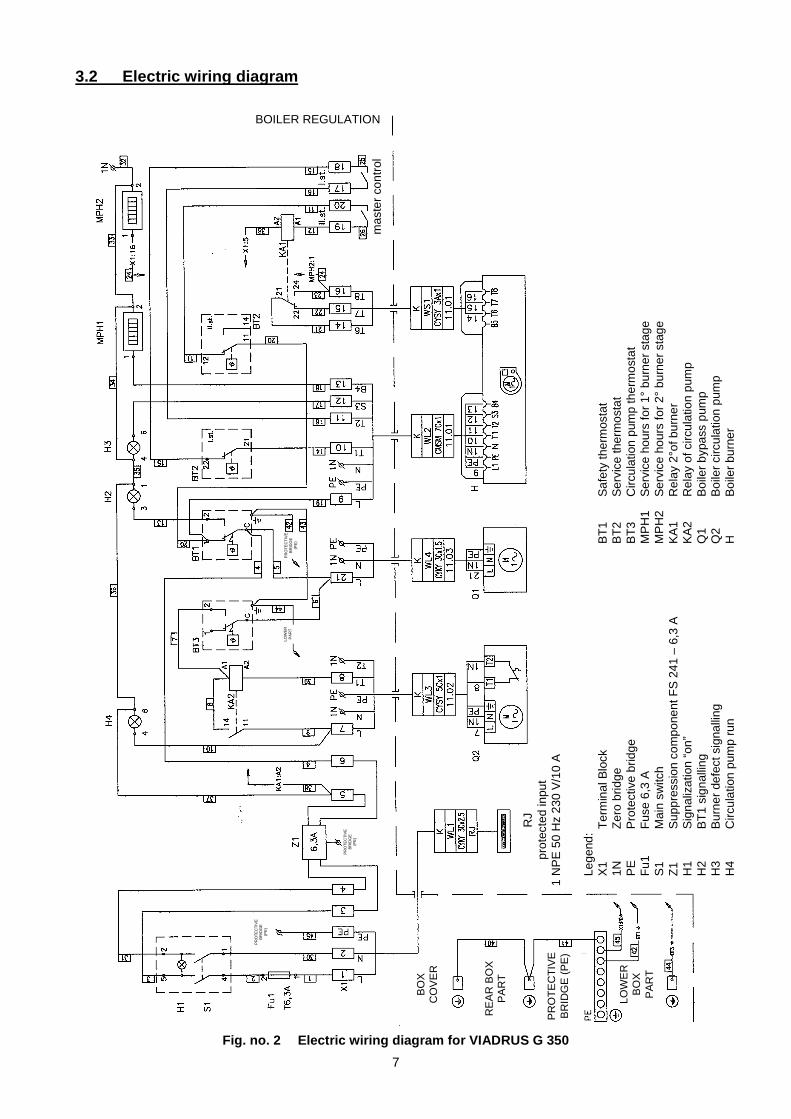
3.2 Electric wiring diagram
Fig. no. 2 Electric wiring diagram for VIADRUS G 350
Lege
nd:
X1
Ter
min
al B
lock
1N
Z
ero
brid
ge
PE
P
rote
ctiv
e br
idge
F
u1
Fus
e 6,
3 A
S
1 M
ain
switc
h Z
1 S
uppr
essi
on c
ompo
nent
FS
241
– 6
,3 A
H
1 S
igna
lizat
ion
“on”
H
2 B
T1
sign
allin
g H
3 B
urne
r de
fect
sig
nalli
ng
H4
Circ
ulat
ion
pum
p ru
n
BT
1 S
afet
y th
erm
osta
t B
T2
Ser
vice
ther
mos
tat
BT
3 C
ircul
atio
n pu
mp
ther
mos
tat
MP
H1
Ser
vice
hou
rs fo
r 1°
bur
ner
stag
e M
PH
2 S
ervi
ce h
ours
for
2° b
urne
r st
age
KA
1 R
elay
2°o
f bur
ner
KA
2 R
elay
of c
ircul
atio
n pu
mp
Q
1
Boi
ler
bypa
ss p
ump
Q2
Boi
ler
circ
ulat
ion
pum
p H
B
oile
r bu
rner
BOILER REGULATION
mas
ter
cont
rol
RJ
prot
ecte
d in
put
1 N
PE
50
Hz
230
V/1
0 A
BO
X
CO
VE
R
RE
AR
BO
X
PA
RT
LOW
ER
B
OX
P
AR
T
LOW
ER
P
AR
T
PR
OT
EC
TIV
E
BR
IDG
E
(PE
)
PR
OT
EC
TIV
E
BR
IDG
E
(PE
)
PR
OT
EC
TIV
E
BR
IDG
E
(PE
)
PR
OT
EC
TIV
E
BR
IDG
E (
PE
)
8
4. Positioning and installation 4.1 Boiler standing in boiler room The installation of the boiler must comply with all requirements of ČSN 06 1008
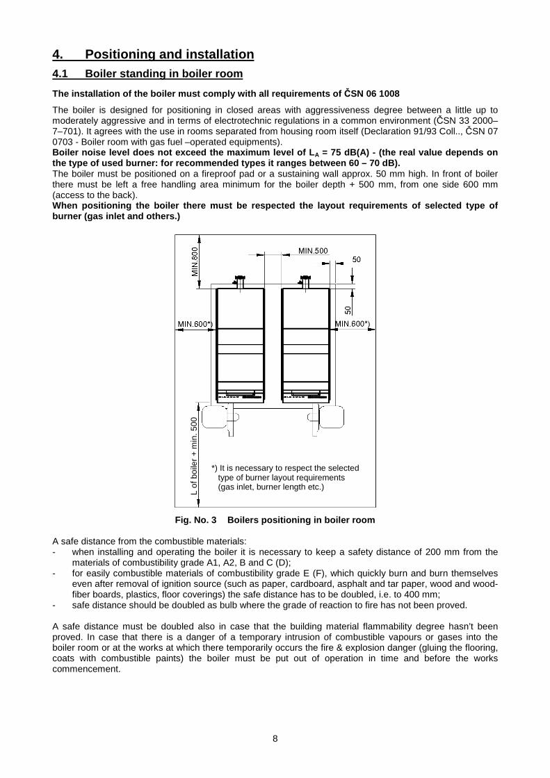
The boiler is designed for positioning in closed areas with aggressiveness degree between a little up to moderately aggressive and in terms of electrotechnic regulations in a common environment (ČSN 33 2000–7–701). It agrees with the use in rooms separated from housing room itself (Declaration 91/93 Coll.., ČSN 07 0703 - Boiler room with gas fuel –operated equipments). Boiler noise level does not exceed the maximum level of L A = 75 dB(A) - (the real value depends on the type of used burner: for recommended types it ranges between 60 – 70 dB). The boiler must be positioned on a fireproof pad or a sustaining wall approx. 50 mm high. In front of boiler there must be left a free handling area minimum for the boiler depth + 500 mm, from one side 600 mm (access to the back). When positioning the boiler there must be respected the layout requirements of selected type of burner (gas inlet and others.)
Fig. No. 3 Boilers positioning in boiler room
A safe distance from the combustible materials: - when installing and operating the boiler it is necessary to keep a safety distance of 200 mm from the
materials of combustibility grade A1, A2, B and C (D); - for easily combustible materials of combustibility grade E (F), which quickly burn and burn themselves
even after removal of ignition source (such as paper, cardboard, asphalt and tar paper, wood and wood-fiber boards, plastics, floor coverings) the safe distance has to be doubled, i.e. to 400 mm;
- safe distance should be doubled as bulb where the grade of reaction to fire has not been proved. A safe distance must be doubled also in case that the building material flammability degree hasn’t been proved. In case that there is a danger of a temporary intrusion of combustible vapours or gases into the boiler room or at the works at which there temporarily occurs the fire & explosion danger (gluing the flooring, coats with combustible paints) the boiler must be put out of operation in time and before the works commencement.
*) It is necessary to respect the selected type of burner layout requirements (gas inlet, burner length etc.)
L of
boi
ler
+ m
in. 5
00
9
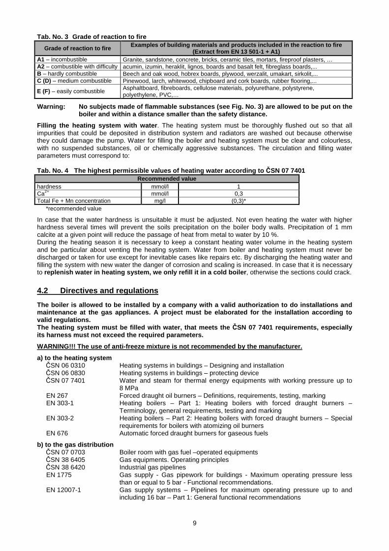
Tab. No. 3 Grade of reaction to fire
Grade of reaction to fire Examples of building materials and products includ ed in the reaction to fire (Extract from EN 13 501-1 + A1)
A1 – incombustible Granite, sandstone, concrete, bricks, ceramic tiles, mortars, fireproof plasters, … A2 – combustible with difficulty acumin, izumin, heraklit, lignos, boards and basalt felt, fibreglass boards,... B – hardly combustible Beech and oak wood, hobrex boards, plywood, werzalit, umakart, sirkolit,... C (D) – medium combustible Pinewood, larch, whitewood, chipboard and cork boards, rubber flooring,...
E (F) – easily combustible Asphaltboard, fibreboards, cellulose materials, polyurethane, polystyrene, polyethylene, PVC,…
Warning: No subjects made of flammable substances (see Fig. No. 3) are allowed to be put on the boiler and within a distance smaller than the safety distance.
Filling the heating system with water . The heating system must be thoroughly flushed out so that all impurities that could be deposited in distribution system and radiators are washed out because otherwise they could damage the pump. Water for filling the boiler and heating system must be clear and colourless, with no suspended substances, oil or chemically aggressive substances. The circulation and filling water parameters must correspond to: Tab. No. 4 The highest permissible values of heating water according to ČSN 07 7401
Recommended value hardness mmol/l 1 Ca2+ mmol/l 0,3 Total Fe + Mn concentration mg/l (0,3)*
*recommended value
In case that the water hardness is unsuitable it must be adjusted. Not even heating the water with higher hardness several times will prevent the soils precipitation on the boiler body walls. Precipitation of 1 mm calcite at a given point will reduce the passage of heat from metal to water by 10 %. During the heating season it is necessary to keep a constant heating water volume in the heating system and be particular about venting the heating system. Water from boiler and heating system must never be discharged or taken for use except for inevitable cases like repairs etc. By discharging the heating water and filling the system with new water the danger of corrosion and scaling is increased. In case that it is necessary to replenish water in heating system, we only refill it in a cold boiler , otherwise the sections could crack.
4.2 Directives and regulations The boiler is allowed to be installed by a company with a valid authorization to do installations and maintenance at the gas appliances. A project must be elaborated for the installation according to valid regulations.
The heating system must be filled with water, that meets the ČSN 07 7401 requirements, especially its harness must not exceed the required parameters.
WARNING!!! The use of anti-freeze mixture is not recommended by the manufacturer.
a) to the heating system ČSN 06 0310 Heating systems in buildings – Designing and installation ČSN 06 0830 Heating systems in buildings – protecting device ČSN 07 7401 Water and steam for thermal energy equipments with working pressure up to
8 MPa EN 267 Forced draught oil burners – Definitions, requirements, testing, marking EN 303-1 Heating boilers – Part 1: Heating boilers with forced draught burners –
Terminology, general requirements, testing and marking EN 303-2 Heating boilers – Part 2: Heating boilers with forced draught burners – Special
requirements for boilers with atomizing oil burners EN 676 Automatic forced draught burners for gaseous fuels
b) to the gas distribution ČSN 07 0703 Boiler room with gas fuel –operated equipments ČSN 38 6405 Gas equipments. Operating principles ČSN 38 6420 Industrial gas pipelines EN 1775 Gas supply - Gas pipework for buildings - Maximum operating pressure less
than or equal to 5 bar - Functional recommendations. EN 12007-1 Gas supply systems – Pipelines for maximum operating pressure up to and
including 16 bar – Part 1: General functional recommendations
10
EN 12007-2 Gas supply systems – Pipelines for maximum operating pressure up to and including 16 bar – Part 2: Specific functional recommendations for polyethylene (MOP up to and including 10 bar)
EN 12007-3 Gas supply systems – Pipelines for maximum operating pressure up to and including 16 bar – Part 3: Specific functional recommendations for steel
EN 12007-4 Gas supply systems – Pipelines for maximum operating pressure up to and including 16 bar – Part 4: Specific functional recommendations for renovation
Act no. 222/94 Coll. on the conditions of enterprise and public service performance in power industry sector and on the state energy inspection
Promulgation 91/93 Coll. of Czech work safety office regarding the work safety assurance in low-pressure buildings
c) to liquid fuel distribution ČSN 65 0201 Combustible liquids. Premises for production, storage and handling Prom. MV ČR č. 35/77 on fire safety at storing and using the heating oil PO 1410/65 of 01. 03. 1966 temporary regulations for heating with heating oil and fuel oil
d) to the electrical network ČSN 33 0165 Electrical regulations. Marking the conductors with colours or digits.
Implementing regulations. ČSN 33 1500 Electrical regulations. Electrical equipments revision ČSN 33 2000-3 Electrical regulations. Electrical equipments Part 3: Setting the basic
characteristics. ČSN 33 2000-4-41 Electric equipments: part 4: Safety chap. 41: Protection against electrical
accident. ČSN 33 2000-5-51 ed. 2 Electrical regulations. Electrical equipments construction. ČSN 33 2130 Electrical regulations. Internal wiring. ČSN 33 2180 Electrical regulations. Connection of electrical devices and appliances. ČSN 34 0350 Electrical regulations. Regulations for mobile connections and cord extension
sets. EN 60079-10 Electrical apparatus for explosive gas atmospheres – Part 10: Classification of
hazardous areas. EN 60079-14 ed.2 Electrical apparatus for explosive gas atmospheres – Part 14: Electrical
installations in hazardous areas (other than mines) EN 60 335-1 ed.2 Household and similar electrical appliances – Safety – Part 1: General
requirements. EN 60 335-2-102 Household and similar electrical appliances – Safety – Part 2-102: Particular
requirements for gas, oil and solid-fuel burning appliances having electrical connections.
EN 60445 ed. 3 Basic and safety principles for man – machina interface, marking and identification – Identification of equipment terminals and conductor terminations
EN 60446 Basic and safety principles for man – machina interface, marking and identification – Identification of conductors by colours or numerals
e) to the chimney ČSN 73 4201 Chimneys and flue gas ducting– designing, implementation and connection of
fuel consumers. The connection must carried out only if approved by a chimney organization wand must meet all provisions of these standards. The chimney must be resistant to combustion gases condensate, otherwise it might be seriously damaged.
f) regarding the fire regulations ČSN 06 1008 Fire safety of heat installations. EN 13501-1 + A1 Fire classification of construction products and building elements – Part 1:
Classification using test data from reaction to fire tests.
g) to the system of HWS heating ČSN 06 0320 Heating systems in buildings – Hot water preparation – Designing and planning ČSN 06 0830 Heating systems in buildings – Safety devices. ČSN 73 6660 House water plumbing

11
5. Order, delivery and assembly 5.1 Order In an order it is necessary to specify following items:
1. Boiler size 2. Demands on elements delivered at request.
5.2 Delivery and accessories Standard:
• In decomposed condition (individual sections on the pallet, the boiler fitting and accessories in a transport package)
• Casing/ jacket including insulation in a cardboard cover • Blank flange for burner (necessary openings for used type of burner are only made during the assembly) • Electric panel in the basic design. • Business technical documentation At request:
• in assembled condition - the boiler body with mounted fitting on the pallet, protected by a foil, accessories stored in boiler. Jacket, including insulation in a cardboard cover.
• delivery with a recommended burner (see tab. No.2) • flange for burner φ 150 mm (φ 140 mm, φ 165 mm) with connection openings according to the ordered
burner
5.3 Assembly process
5.3.1 Installation of the boiler body • Boiler is positioned on the completely horizontal supporting brickwork. • The rear section is positioned on the supporting brickwork and supported with a strut. • After drilling the insert holes in the rear section must be thoroughly removed the residues of conservation
agent and impurities. • The outer edges of insert holes must be removed by means of a cabinet file and the insert opening is
painted with oil or boiled –oil paint. • Put the inserts painted with oil or boiled –oil paint into insert openings and tap by means of a wooden
mallet. The insert must be properly and evenly inserted. • Apply a sufficient layer of cement boiler on contact ground surfaces of ribs. • Put the section on the protruding part of inserts so that the inserts can be easily inserted into inserting
holes of the section and tap it by means of a wooden mallet and tighten by means of tightening tool. NOTE: The gap between the sections be the same around the whole circumference during the tightening operation .
• Similarly tighten all remaining sections. WARNING: It is forbidden to tighten more than one boiler section at once.
• Secure the boiler body with anchor bolts. WARNING: Tighten the nuts of anchor bolts only slightly in order to dilate the boiler after heating .
• Fill the circumferential groove (dovetail) resulting from tightening always two sections completely with boiler cement around the whole circumference
In Figure 4 is shown mounting the 4th section of boiler and other sizes vary in the length of anchor bolts, the number of inserts and medium sections
12
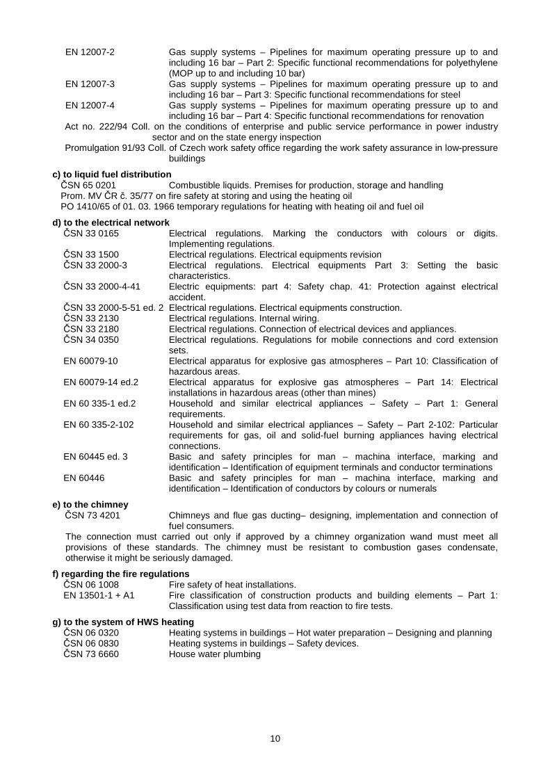
Fig. no. 4 Installation of the boiler body of 4 sections size
Fig. no. 5 Boiler body after installation
5.3.2 Pressuring the boiler body • Seal the bottom hole of the front section with stopper G 2. • Seal the upper hole of the front section with stopper G 2" with bore 1/2". • Seal all threaded joints with hemp. • Connect the flange with a mouthpiece to the bottom hole of rear section with the possibility to connect
the water under pressure. • Close the upper hole of rear section (the output of heating water) with a flange with sealing and bleeder
valve. • Open the bleeder valve and fill the boiler body with cold water, close the valve. • Do pressuring by applying the test overpressure of 800 kPa (8 bar) for 15 minutes. During the pressure
test no leaks are allowed to appear. • Perform the visual inspection.
1. Screw M 8 x 30 2 Screw M 12 x 30 3 Rear section 4 Middle section 5 Boiler insert Ø 88 mm 6 Front section 7 Reduction C241 2 1/2" 8 Stopper G 2 " 9 Thermostat well 1/2 " 10 Check valve of manometer
1/2" 11 Anchor bolt of section 4 12 Washer 12 13 Nut M12 14 Screw M12 x 65 (with eye) 15 Screw M 12 x 80
13
5.3.3 Installation of the burner plate
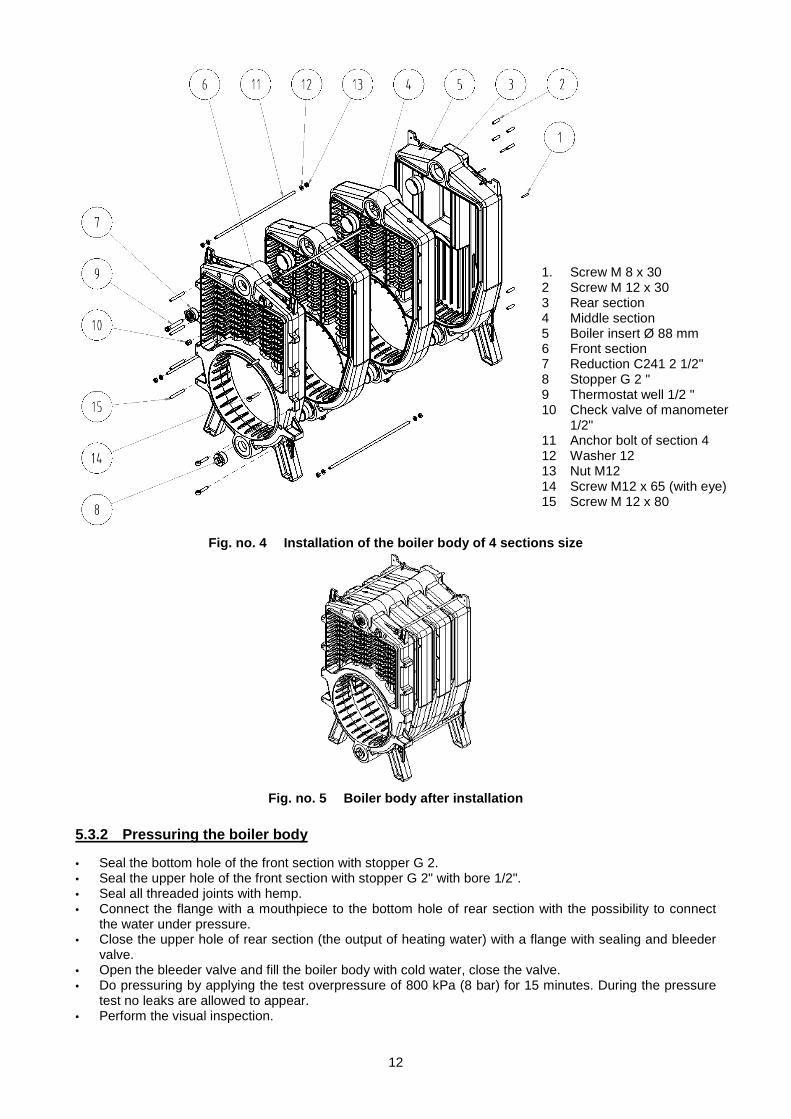
Fig. no. 6 Installation of the burner plate
5.3.4 Mounting of closing plate
Fig. no. 7 Mounting of closing plate
1. Casting of the burner plate 2. Insulation of the burner plate 3. Washer Ø 48 4. Screw M8 x 40 5. Plate sight glass 6. Small valve 7. Seal of the sight glass 8. Mica of the sight glass 9. Screw M 4 x 8 10. Sealing Cord Ø 10 mm
1 Closing plate 2 Insulation of closing plate 3 Screw M8 x40 4 Washer Ø 48 5 Sealing Cord Ø 10 mm
14
5.3.5 Installation of flue throat
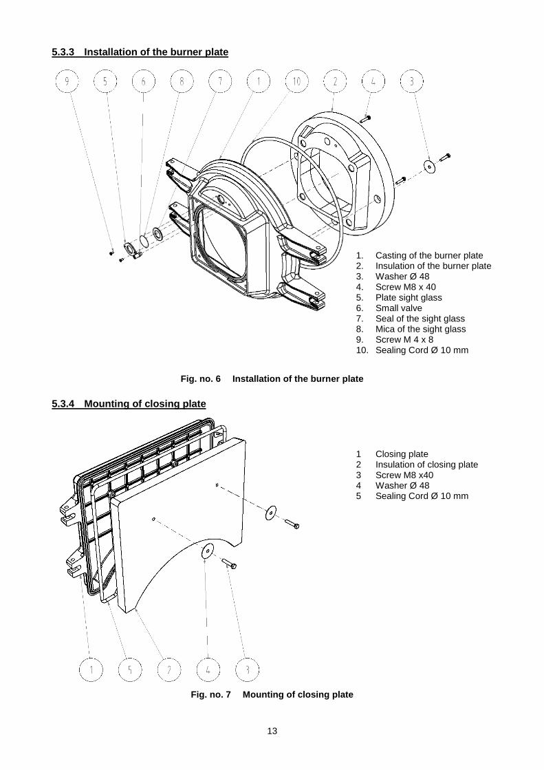
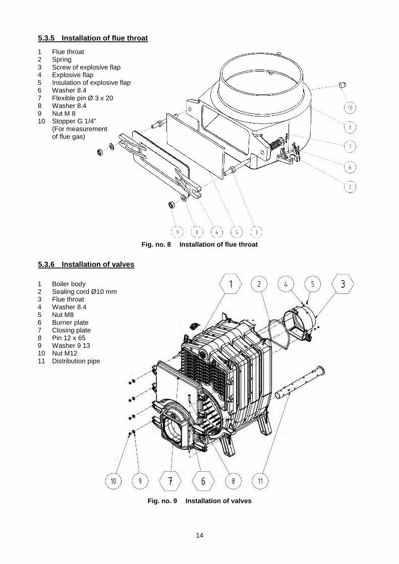
Fig. no. 8 Installation of flue throat
5.3.6 Installation of valves
Fig. no. 9 Installation of valves
1 Flue throat 2 Spring 3 Screw of explosive flap 4 Explosive flap 5 Insulation of explosive flap 6 Washer 8.4 7 Flexible pin Ø 3 x 20 8 Washer 8.4 9 Nut M 8 10 Stopper G 1/4"
(For measurement of flue gas)
1 Boiler body 2 Sealing cord Ø10 mm 3 Flue throat 4 Washer 8.4 5 Nut M8 6 Burner plate 7 Closing plate 8 Pin 12 x 65 9 Washer 9 13 10 Nut M12 11 Distribution pipe
15
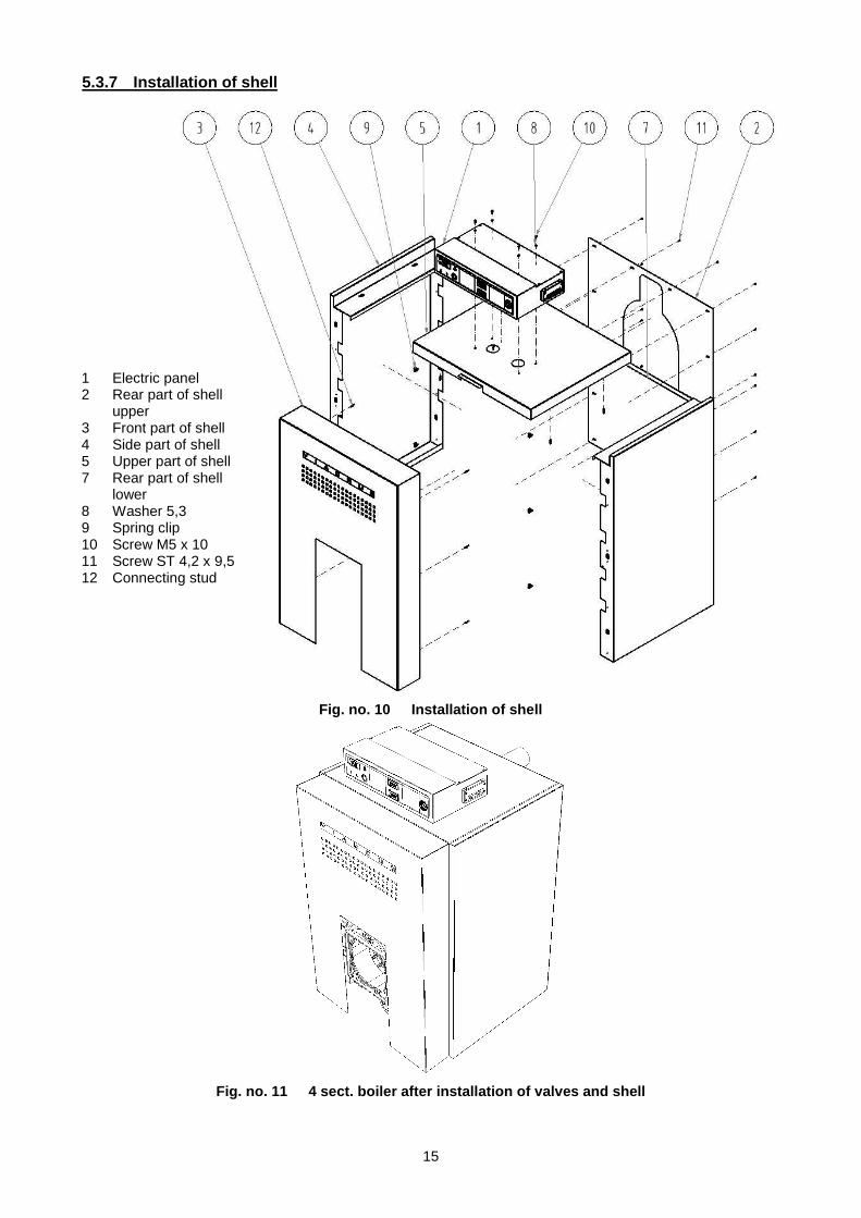
5.3.7 Installation of shell
Fig. no. 10 Installation of shell
Fig. no. 11 4 sect. boiler after installation of valves and shell
1 Electric panel 2 Rear part of shell
upper 3 Front part of shell 4 Side part of shell 5 Upper part of shell 7 Rear part of shell
lower 8 Washer 5,3 9 Spring clip 10 Screw M5 x 10 11 Screw ST 4,2 x 9,5 12 Connecting stud

16
6. Commissioning Putting the boiler into operation, setting the heat output and any intervention into the electrical part of boiler or connection of further control elements can only be done by service organization authorized to do the service works and an authorized firm for servicing the burner being operated.
1. Burner installation and assembly, its adjustment and putting the boiler with a burner into operation must be confided to the care of a burner supplier ´s service firm. The service firm will give the user a training in operation and provide him with burner use manual and guarantee plus after-guarantee repairs.
2. Before putting the boiler into operation a record must be made in Inspection book.
6.1 Checking activities before initiation Before putting the boiler into operation it is necessary to check:
a) filling the heating system with water (thermo-manometer check) and tightness of the system
b) setting the boiler thermostat stage II. (rated power/ nominal output) to 60 - 85 oC.
b) opening all slide-valves and valves between the boiler and heating system
c) opening the fuel inlet
d) inlet pressure of fuel before entering the boiler according to the burner documentation
e) connection to the electricity network 230 V/380 V 50 Hz/TN-S
f) connection to the chimney (the necessary chimney draught is 5 Pa).
g) max. overpressure in combustion chamber is 0,2 kPa (2 mbar). The probe positioned on burner plate serves for overpressure measuring in combustion chamber.
Setting the regulation elements:
- regulation thermostat stage I. (reduced output) – permanently set by manufacturer to 85 °C.
- safety thermostat - permanently set by manufacturer to 100 °C.
6.2 Boiler conversion from „liquid fuels“ to „ gas fuels“ and back The boiler conversion from „liquid fuels“ to „gas fuels“ and back doesn’t require any adaptations apart from the burner and adequate flange exchange for a burner. Before the conversion we recommend to check the body, the combustion gases routes and their thorough cleaning. This conversion (burner exchange) will only be required by a customer at a contractual service firm – organization entitled to be engaged in this activity.
17
7. Boiler operation by user The boiler works automatically according to the regulation elements setting and users only do the following operating activities that they are obliged to familiarize with before putting the boiler into operation as follows:
1. Switching on and switching off the boiler by means of network switch on the boiler electro-panel.
2. Setting and checking the required heating water temperature within 60 – 85 °C limits.
3. Unblocking the safety thermostat. In case that the boiler is switched off by a safety thermostat, the signal lamp on electro-panel is alight thus signalling that the temperature has been exceeded. The user can unblock the thermostat by means of the pushbutton "unblocking" at the safety thermostat positioned at the rear panel of control box.
4. Pressure check in heating system
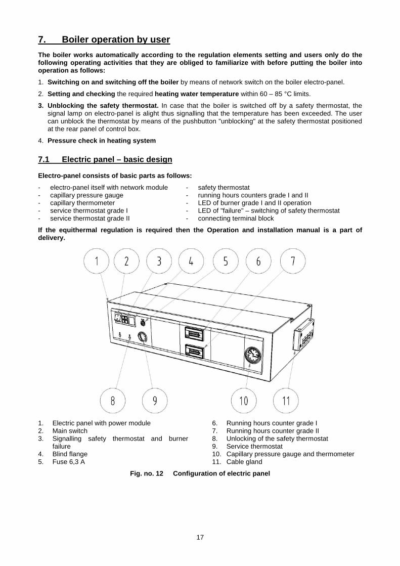
7.1 Electric panel – basic design Electro-panel consists of basic parts as follows:
- electro-panel itself with network module - capillary pressure gauge - capillary thermometer - service thermostat grade I - service thermostat grade II
- safety thermostat - running hours counters grade I and II - LED of burner grade I and II operation - LED of "failure" – switching of safety thermostat - connecting terminal block
If the equithermal regulation is required then the Operation and installation manual is a part of delivery.
1. Electric panel with power module 2. Main switch 3. Signalling safety thermostat and burner
failure 4. Blind flange 5. Fuse 6,3 A
6. Running hours counter grade I 7. Running hours counter grade II 8. Unlocking of the safety thermostat 9. Service thermostat 10. Capillary pressure gauge and thermometer 11. Cable gland
Fig. no. 12 Configuration of electric panel
18
8. IMPORTANT WARNINGS 1. The boiler only can be used for the purpose that it is destined for. 2. The boiler after initiation works automatically. It only can be operated by adult persons familiar
with this manual and the burner operation manual. 3. The boiler is not destined for the use by persons (incl. children) whose physical, sensual or
mental disability or lack of experience and knowledge prevent them from a safe use of the appliance unless they are supervised or if they were not instructed on the use of appliance by a person responsible for their safety.
4. Children should be supervised in order to ensure that they do not play with the appliance. 5. The boiler must be operated according to the manual and related standards. 6. The air of combustion must not contain a high moisture and dustiness. If their occurrence
cannot be excluded in the environment related to the boiler location there must be brought the air of combustion into the boiler room directly from outdoor environment.
7. The boiler room must be kept in a clean and dust-free condition. From the boiler room area there must be excluded all sources of pollution and during the works (insulation works, boiler room cleaning) that cause the dustiness the boiler must be put out of operation. Even a partial burner clogging with dirt devalues the combustion process and endangers an economical and reliable boiler operation.
8. To prevent the boiler from retting followed by low-temperature corrosion at the places where a more permanent run at lower temperatures can be expected (transition periods, at the heating system with a large heating water volume, law-temperature regime etc.) it is necessary to ensure that the return water temperature does not drop below 50 °C. The best way is the creation of boiler own circuit.
9. Adjustment of burner stage I. (reduced output) must be done with regard to the combustion gases temperature in a way making sure that it doesn’t drop below 130 °C.
10. Water from boiler and heating system should never be taken for use neither discharged apart from the indispensable cases like system repairs. The water discharge increases the corrosion and scale formation danger. If it is necessary to refill water always chemically treated in heating system then we only refill the cold boiler in order to avoid the boiler sections breaking.
11. If there occurs the boiler failure condition, the lamp signalling the burner failure lights up at the boiler electro-panel. In case of electricity outage the burner is switched off and after voltage recovery in el. network there will automatically run a new burner start.
12. The burner operation failures are in detail described in burners operation manual, including the ways of their elimination and they must be followed.
13. In case of a long-term shut-down of a boiler this boiler must be disconnected from el. network. 14. In case that there occurs the danger of flammable vapours or gases development and their
intrusion into the boiler room, or at the works where there temporarily occurs the fire or explosion danger (gluing the flooring, painting with flammable paints), the boiler in time and before works initiation must be put out of operation.
15. No objects made of combustibles are allowed to be put on boiler and within a distance lower than a safety distance from the boiler.
16. During assembly, installation and operation of the appliance it is necessary to comply with standards that apply in the relevant country of destination.
17. The user is obliged to confide the commissioning, regular maintenance and failures elimination only to the care of a professional contractual service accredited by VIADRUS a.s., the boilers manufacturer, VIADRUS division, otherwise the boiler proper function guarantee doesn’t apply. “VIADRUS G 350 boiler quality and completeness certificate “after having been filled in by contractual service organization serves as the “Guarantee certificate“.
18. On the boiler there must be carried out once a year a regular maintenance according to the next chapter.
19. During assembly, installation and operation of the appliance it is necessary to comply with standards that apply in the relevant country of destination.
If you fail to meet these conditions you cannot requisite the guarantee repairs.
19
9. Maintenance All interventions are only allowed to be done by contractual service organization trained by the manufacturer.
1. Disconnect the boiler from the el. network.
2. Close the fuel inlet to the burner.
3. Open the burner plate with a burner and the sealing plate.
4. Check sooting of the convection surfaces and perform chemical cleaning (e.g. Metano Therm for ZP, EC-MIX for TOEL – according to the manufacturer's instructions). Remove the residues after cleaning with a brush attached to the boiler both from the combustion chamber and the flue throat after removing the cleaning cover – the explosive valve. With the explosive valve and springs must not be manipulated.
5. Check the burner orifice clogging. If the burner orifice is dirty it must be cleaned according to the burner manufacturer ´s instructions.
6. A careful closing of the burner plate with the burner, the sealing plate and all small covers – check their tightness .
7. Mount the holder with explosion shutter.
8. Open the fuel supply; connection to el.network and boiler start-up.
9. Check the tightness of fuel supply to the burner.
10. Setting and adjusting of boiler heat output.
10. Instructions for product disposal after its service life VIADRUS a.s., is contractual partner of firm EKO–KOM a.s. with client number F00120649. The packages comply with EN 13427. With regard to the fact that the product is constructed of common metal materials the individual parts are recommended to be disposed of as follows: - exchanger (grey cast-iron), through a firm dealing with waste salvage and disposal - piping, jacketing, through a firm dealing with waste salvage and disposal - other metal parts, through a firm dealing with waste salvage and disposal - insulation material ROTAFLEX into the common waste
We recommend to dispose the packages in the following way: - plastic foil, cardboard cover, use a salvage point - metal strapping tape, use a salvage point - wooden base, is designated for a single usage and no longer can be used as a product. Its disposal is
subject to Act. 477/2001 Sb. a 185/2001 Coll. as amended.
In case that the product has lost its manufacture qualities there can be taken advantage of a repeated product take-off (if it is introduced) in case of originator ´s statement saying that this is the waste and it will be handled according to the legislation valid in the particular country.
11. Failures and their elimination - the failures elimination can only be done by a trained contractual service organization and this
organization will make an entry in the guarantee certificate supplement
- in case that there is repeatedly blocked the safety thermostat it is also necessary to call a contractual service worker
- the burners operation failures are in detail described in Burners operation manual, including the ways of failures elimination and they must be followed.
20
12. Guarantee and liability for defects VIADRUS a.s. gives a guarantee: – For boilers 24 months after the boiler putting into operation, but maximum 30 months after the date it
was dispatched from the manufacturing factory. – For boiler drum 5 years after the date its dispatch from the manufacturing factory.
For the guarantee validity the manufacturer requires: – in terms of Act No.222/94 Coll. „ On entrepreneurship and state administration execution
conditions in certified branches and on State energy inspection” Regulation No.91/93 Coll. issued by „Czech Labour Safety Office for ensuring the labour safety in law-pressure boiler rooms “ and ČSN 38 6405, EN 1775 to inspect regularly the boiler. The inspections can only be done by an authorized organization (contractual service), accredited by VIADRUS a.s. and the manufacturer of the burner being operated.
– To document all records of carried out guarantee and after-guarantee repairs and regular annual boiler inspections in the guarantee certificate supplement which belongs to the boiler revision book.
The guarantee doesn’t apply to: - Faults caused by improper assembly and improper attendance of the product and faults caused
by improper maintenance see chap. 9 - Faults and damage caused by failure to observe water quality in heating system see chap. no. 4.1
and 4.2 or by using the anti-freeze mixture - product damage caused by transport or other mechanical damage - failures caused by improper storage - Faults caused by failure to observe instructions stated in this manual
Every failures notification must be done immediately after having found the failures and always in writing.
When the above instructions aren’t followed the guarantees provided by manufacturer will not be recognized.
The manufacturer reserves the right to changes made within the product innovation that needn’t be included in this manual.
21
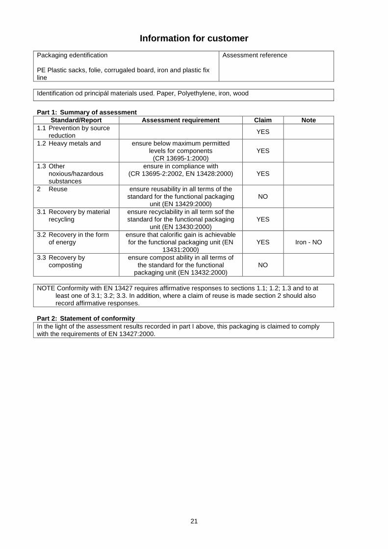
Information for customer
Packaging edentification PE Plastic sacks, folie, corrugaled board, iron and plastic fix line
Assessment reference
Identification od principál materials used. Paper, Polyethylene, iron, wood
Part 1: Summary of assessment
Stand ard/Report Assessment requirement Claim Note 1.1 Prevention by source
reduction
YES
1.2 Heavy metals and ensure below maximum permitted levels for components
(CR 13695-1:2000) YES
1.3 Other noxious/hazardous substances
ensure in compliance with (CR 13695-2:2002, EN 13428:2000) YES
2 Reuse ensure reusability in all terms of the standard for the functional packaging
unit (EN 13429:2000) NO
3.1 Recovery by material recycling
ensure recyclability in all term sof the standard for the functional packaging
unit (EN 13430:2000) YES
3.2 Recovery in the form of energy
ensure that calorific gain is achievable for the functional packaging unit (EN
13431:2000) YES Iron - NO
3.3 Recovery by composting
ensure compost ability in all terms of the standard for the functional
packaging unit (EN 13432:2000) NO
NOTE Conformity with EN 13427 requires affirmative responses to sections 1.1; 1.2; 1.3 and to at
least one of 3.1; 3.2; 3.3. In addition, where a claim of reuse is made section 2 should also record affirmative responses.
Part 2: Statement of conformity In the light of the assessment results recorded in part I above, this packaging is claimed to comply with the requirements of EN 13427:2000.

22

23

24Date of revision 10/2013 - GB
Related Documents