Manual DTSG 4-Reversible MSF-Vathauer Antriebstechnik GmbH & Co KG Am Hessentuch 6-8 32758 Detmold Tel: ++49 (0) 5231-66193+63030 Fax: ++49 (0) 5231-66856 email: [email protected] www.msf-technik.de Page 1 of 25 Manual Digital Clock Switching Device DTSG 4 – Reversible Stand: 11/2002 Date: 13.12.2013

Welcome message from author
This document is posted to help you gain knowledge. Please leave a comment to let me know what you think about it! Share it to your friends and learn new things together.
Transcript

Manual DTSG 4-Reversible
MSF-Vathauer Antriebstechnik GmbH & Co KG Am Hessentuch 6-8 32758 Detmold Tel: ++49 (0) 5231-66193+63030 Fax: ++49 (0) 5231-66856 email: [email protected] www.msf-technik.de Page 1 of 25
Manual
Digital Clock Switching Device
DTSG 4 – Reversible
Stand: 11/2002
Date: 13.12.2013
Manual DTSG 4-Reversible
MSF-Vathauer Antriebstechnik GmbH & Co KG Am Hessentuch 6-8 32758 Detmold Tel: ++49 (0) 5231-66193+63030 Fax: ++49 (0) 5231-66856 email: [email protected] www.msf-technik.de Page 2 of 25
Warranty
According to the current general terms of delivery and payment MSF- Vathauer
Antriebstechnik GmbH & Co. KG provides a warranty of 12 months (in single shift) from delivery on all electronic devices covering design, material or faulty workmanship.
MSF- Vathauer Antriebstechnik reserves the right to change the contents of this operation manual and the product specifications contained therein without prior notice.
The copyright of this documentation is reserved by MSF-Vathauerer Antriebstechnik GmbH & Co. KG .
Attention!
Read this manual carefully and completely. Start with the installation and commissioning only after reading.
Technical changes reserved

Manual DTSG 4-Reversible
MSF-Vathauer Antriebstechnik GmbH & Co KG Am Hessentuch 6-8 32758 Detmold Tel: ++49 (0) 5231-66193+63030 Fax: ++49 (0) 5231-66856 email: [email protected] www.msf-technik.de Page 3 of 25
Index 1. Safety and operating instructions 4 1.1 General 4 1.2 Intended Usage 4 1.3 Delivery and storage 4 1.4 Installation 5 1.5 Electrical connection 5 1.6 Operation 5 1.7 Maintenance and Servicing 5 1.8 Safety and Installation instructions 6 1.9 European EMC directive 6 2. Assembly and Installation 7 2.1 Cabling directives 7 2.2 Measures to secure the EMC 7 2.3 Grounding, Earthen, Potential compensation 7 2.4 Filters 8 2.5 Screening 8 3. Technical features 9 4. Operating and connection elements at the front side 10 4.1 Display 10 4.2 The “Modus” button 11 4.3 The “Set” Button 11 4.4 External auxiliary connection 11 5. Operating modes 12 6. Changing the parameters of the running and pausing times 13 7. Changing the trigger mode 13 8. Impulse suppression during retriggering 14 9. Permanent operation 14 10. Recognition of Position 15 11. Light Barrier at band end 15 12. Clear function 15 13. Reversible function 15 Appendix A Menu structure cycle mode 16 Appendix B Menu structure switching mode 17 Appendix C Changing the running or pausing time 18 Appendix D Setting the Trigger Mode 19 Appendix E Setting the time for suppressed impulse 20 Appendix F Assignment of terminales 21 Appendix G Assignment of the Sub-D-Socket 22 Appendix H Jumper connection 23 Appendix I Displays and list of errors 24
Manual DTSG 4-Reversible
MSF-Vathauer Antriebstechnik GmbH & Co KG Am Hessentuch 6-8 32758 Detmold Tel: ++49 (0) 5231-66193+63030 Fax: ++49 (0) 5231-66856 email: [email protected] www.msf-technik.de Page 4 of 25
1. Safety and operating instructions for the digital c lock switching device
1.1. General As long as any electrical equipment and machinery is switched on, the operator may touch voltage leading and non-isolated conductors or rotating parts when he removes the covers and the prescribed protections, in handling the machine improperly, or during service work or improper use, and may well cause personal injuries and material damage. All works with transport, installation and commissioning as well as maintenance have to be done by properly trained personnel (regard IEC 364 res. VENELEC HD 384 or DIN VDE 0100 and IEC report 664 or DIN VDE 0110 and national accident prevention regulations or VGB 4). Qualified personnel in terms of these basic security considerations are persons that are used to installation, assembly, commissioning and operation of the product and that have qualifications according to their work (defined in IEC 364 or DIN VDE 0105).
1.2. Intended Usage Digital-clock-switching devices are components for installation within machines that are operated in industrial plants. The commissioning of digital-clock-switching devices is prohibited until it is as curtained that the machine that includes the digital clock-timer follows the restrictions of the EU directive 89/ 392/ EWG (machine directive). The digital-clock-switching device matches the protection goals of the low voltage directive 73/ 231/ EWG and the harmonized norms of the series prEN 50178/ DIN VDE 0160 in connection with EN 60439-1/ DIN VDE 0660 part 500 and EN 601146/ DIN VDE 0558. The operation is only permitted according to the EMC directive (89/ 336/ EWG). The technical data and information to connection conditions are to be found at the rating plate or the documentation and have to be completely fulfilled.
1.3. Transport and Storage The considerations for transport, storage and the appropriate handling must be regarded. Damages recognized after delivery must be immediately announced to the transport company. If applicable, notify the distributor before commissioning. Regard the environmental conditions according to prEN 50178.
Manual DTSG 4-Reversible
MSF-Vathauer Antriebstechnik GmbH & Co KG Am Hessentuch 6-8 32758 Detmold Tel: ++49 (0) 5231-66193+63030 Fax: ++49 (0) 5231-66856 email: [email protected] www.msf-technik.de Page 5 of 25
1.4. Installation Installation and cooling of the devices must be according to the specifications of the concerning documentation. The digital-clock-switching device must be secured from improper operational demands. Take care to not bend electronic devices and/or change isolation distances. Avoid touching electronic elements and contacts. Digital-clock-switching devices contain electrostatic imperiled elements. Improper handling may easily destroy these elements. Inbuilt electrical components must not be destroyed (health risk in certain circumstances).
1.5. Electrical connection At working at current converters with supplied power regard the valid national accident prevention regulations (e.g. VGB 4). The electrical installation has to be done according to the valid directives (e.g. cable diameters, fuse protection, ground wire connection). More detailed information is to be found in the documentation. Compliance with the limits for the plant according to the EMC juridical directive is in responsibility of the manufacturer of the plant. Considerations for the EMC-compatible installation like screening, grounding, alignment of filters and laying of cables are to be found in the documentation of the digital- clock-switching device.
1.6. Operation Plants that contain digital-clock-switching device have to be provided, if applicable, with additional observation and security installations according to the concerning valid security directives, e.g. act on technical work equipment, accident prevention regulations etc. The documentation of the manufacturer has to be regarded. After disconnection of the digital-clock-switching device from the supply voltage, voltage conducting device parts and cable conductors must not be immediately touched because of possibly charged condensers. Please regard the according notification signs at the frequency inverters. During operation all covers must kept closed.
1.7. Maintenance and servicing The documentation of the manufacturer has to be regarded.
Manual DTSG 4-Reversible
MSF-Vathauer Antriebstechnik GmbH & Co KG Am Hessentuch 6-8 32758 Detmold Tel: ++49 (0) 5231-66193+63030 Fax: ++49 (0) 5231-66856 email: [email protected] www.msf-technik.de Page 6 of 25
1.8. Safety and Installation considerations
Digital-clock-switching devices from MSF- Vathauer Antriebstechnik are operating resources for the deployment in industrial high-voltage plants and are operated with voltages that may cause heavy injuries or death when touching!
• Installations and works may only be executed by qualified electrical trained personnel and at voltage free device. The user manual has to be available at any time and has to be consequently regarded.
• The local directives for building electrical plants and accident prevention regulations must be fulfilled.
• The device is up to 5 minutes after disconnecting from the voltage conducted with dangerous voltage. Due to this, opening of the device or removing the cover is only permitted 5 minutes after disconnecting the device from voltage. Before turning the mains voltage on all covers must be mounted again.
• Also at motor standstill (e.g. due to electronics lock, short circuit at the output clamps or blocked drive) the voltage circuit clamps, motor clamps and clamps for the brake resistance may conduct dangerous voltage. A motor standstill is not identical with a galvanic disconnection from the mains voltage
• Attention : The digital-clock- witching device may, depending on the settings, start automatically after powering the mains voltage.
• The digital-clock-switching device must not be operated without effective ground connection that fulfils the local directives for high leakage current (>3.5mA).
• With the digital-clock-switching device common FI circuit breakers as single protection are not applicable when the local directives do not allow a possible direct current component in the error current. The standard FI circuit breakers have to fulfill the new construction type acc. VDE 0664.
Attention! Danger to Life! The power supply conducts voltage under certain cir cumstances for up to 5 minutes after turning off the mains voltage. Converter clam ps, drive cables and drive clamps may conduct voltage! Touching open or free clamps, cables and device par ts may cause heavy injuries or death!
Attention • Children and the public must not have access to the device! • The device may only be used for the purpose intended by the manufacturer. Unauthorized
changes and the use of replacement parts and additional devices that are not sold or approved by the manufacturer may cause fire, electric shocks and injuries.
• Keep the manual in reach and make it available for every user!
Manual DTSG 4-Reversible
MSF-Vathauer Antriebstechnik GmbH & Co KG Am Hessentuch 6-8 32758 Detmold Tel: ++49 (0) 5231-66193+63030 Fax: ++49 (0) 5231-66856 email: [email protected] www.msf-technik.de Page 7 of 25
European EMC directive If the digital-clock-switching device is installed according to the recommendations of this manual it fulfills the requirements of the EMC directive according to the EMC product norm for motor driven systems EN 61800-3.
2. Assembly and Installation
2.1 Cabling directives The digital-clock-switching devices are developed for the operation in industrial environments where high values of electromagnetic interferences are expected. In general, a professional installation ensures a riskless and error-free operation. If limits are required that exceed the EMC directive limits, the following directives are recommended.
1. Please make sure that all devices in the control cabinet are connected together at a shared grounding point or rail with short cores and great diameter are properly grounded. It is especially important that every control device connected to digital-clock-switching device (e.g. automation devices) is connected via a short core with high diameter at the same grounding point like the digital-clock-switching device.
2. The PE conductor of the drive controlled by the digital-clock-switching device should preferably directly connected to the ground connection connected with the heat sink together with the PE of the power supply of the concerning inverter. The existence of a central grounding rail within the control cabinet and the connection of all ground cables to this rail normally guarantee an error-free operation.
3. As far as possible you should use screened cables for the control. The cable ends have to be terminated carefully and it must be taken care that the cores are not unscreened over long distances. The screen of analog set point cables should only be grounded at the frequency inverter single-sided. Not used cores of the control cores should be grounded.
4. The control cores have to be laid in the most possible distance from the load cores using separated cable trenches etc. Cable crosses should possibly get an ankle of 90°.
5. Make sure that contactors and relays in the control cabinets are suppressed either by RC connection or varistors in case of ac contactors or by „ free wheeling diodes“ at dc contactors, where the dejam devices have to be connected at the contactor coil . The dejamming is especially important when the contactors are controlled by the relays in the digital-clock- switching device.
At installation of the digital-clock-switching device you must not disregard safety directives!
2.2 Measures to secure EMC The following measures are to secure the EMC, which are of absolute necessity to the inverter technology. The inverter fulfills the demands of the high noise immunity and the slight-noise emissions for the usage in industries, under the guidelines of this manuals installation consideration.
2.3 Grounding, earthen, potential compensation The correct professional grounding or earthen guarantees the protection of the staff against dangerous touch voltages (input, output and intermediate circuit voltage). Parasitic currant inductance and low-impedance potential compensation are important measures to reduce electromagnetic influences.

Manual DTSG 4-Reversible
MSF-Vathauer Antriebstechnik GmbH & Co KG Am Hessentuch 6-8 32758 Detmold Tel: ++49 (0) 5231-66193+63030 Fax: ++49 (0) 5231-66856 email: [email protected] www.msf-technik.de Page 8 of 25
2.4 Filters Filters are inserted into the lead-bound transfer way between the source of interference and the interference suppressor, which is to reduce lead-bound transmissions and to increase the noise immunity. This is why mains-filter and output chokes have been integrated into the digital-clock-switching device, and have, in fact, reached the EMC conformity. Additional, external filter may have a negative effect on the noise emission.
2.5 Screening Screening is used for decoupling fields between two spatially separate areas, i.e. is also used to decrease the emission of electromagnetic radiation and to increase the noise immunity. The consistent use of metal cases is one of the most important standard measures to safeguard the EMC.

Manual DTSG 4-Reversible
MSF-Vathauer Antriebstechnik GmbH & Co KG Am Hessentuch 6-8 32758 Detmold Tel: ++49 (0) 5231-66193+63030 Fax: ++49 (0) 5231-66856 email: [email protected] www.msf-technik.de Page 9 of 25
3. Technical features The digital clock timer unit DTSG 4 controls 3-phase motors with freely selectable run and break times. The phases are switched by semiconductor-relays in the zero point so that high current peaks are avoided. A menu navigation helps the user with the adjustment of the operating parameters via only two buttons. Additionally, an external pulse emitter, that causes a motor-start, can be connected. Here you may initialize both, a unique release as well as a repeated release (Retrigger). All operating parameters are stored in a not-fleeting storage (E²Prom) that allows to abstain on a battery for memory continuity. The device can be installed in different positions, hereby the device recognizes a "over head position" through a built-in switch and steers the display accordingly. Special features � High interference resistance as well as low interference emission due to the
aluminum casing and integrated line and output filter (EMV conform design). � Protection class IP54 � Different mounting options grant an optimal assembly possibility at the machine. � No additional operating expense at the direct installation at machines through pre-
wired network and motor cable on customer wish. � Automatic recognition of the mounting position and therefore the automatic correction
of the display. � Pluggable standard clamps. � Break and runtime is adjustable in a wide range from 0,1s to 9999s. � Retriggerable (repeated start) � Adjustable debounce time for trigger. � All signals available at clamps. � Edge or level control of the trigger.
� Connection option for a light barrier at band end. � Connection option for a caliper for band clearing.
Manual DTSG 4-Reversible
MSF-Vathauer Antriebstechnik GmbH & Co KG Am Hessentuch 6-8 32758 Detmold Tel: ++49 (0) 5231-66193+63030 Fax: ++49 (0) 5231-66856 email: [email protected] www.msf-technik.de Page 10 of 25
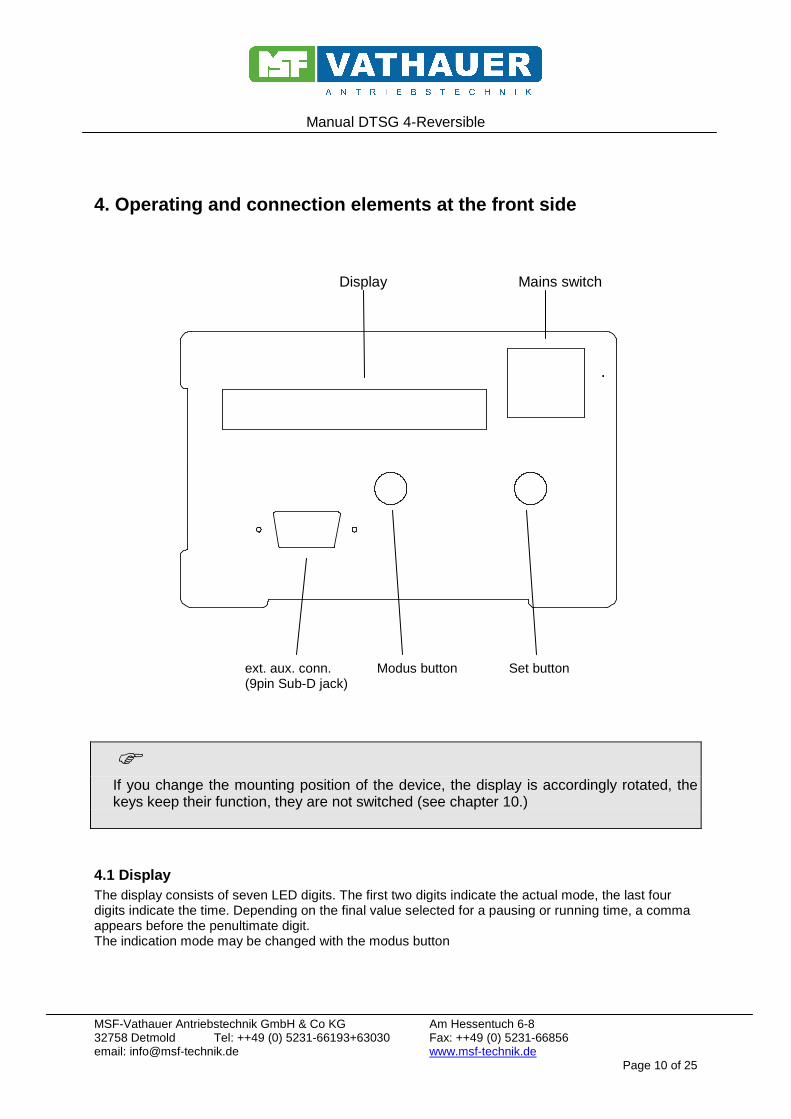
4. Operating and connection elements at the front s ide
Display Mains switch
ext. aux. conn. Modus button Set button (9pin Sub-D jack)
� If you change the mounting position of the device, the display is accordingly rotated, the
keys keep their function, they are not switched (see chapter 10.)
4.1 Display The display consists of seven LED digits. The first two digits indicate the actual mode, the last four digits indicate the time. Depending on the final value selected for a pausing or running time, a comma appears before the penultimate digit. The indication mode may be changed with the modus button

Manual DTSG 4-Reversible
MSF-Vathauer Antriebstechnik GmbH & Co KG Am Hessentuch 6-8 32758 Detmold Tel: ++49 (0) 5231-66193+63030 Fax: ++49 (0) 5231-66856 email: [email protected] www.msf-technik.de Page 11 of 25
4.2 The „Modus“button With the modus button, you may „leaf“through the display. When you have pressed this key you see another parameter res. you return to normal operation. When you set the parameter can be advanced by one position with the "Set" button. Possible displays are - and time The motor is at its standstill. The pausing time is
counted up Time only The motor runs. The running time is counted up - ---- The motor is at its standstill. The unit is waiting for
external impulses LF = Running time The time during which the motor is switched on. PA = Pausing time ((only for cycles) The time during which the motor is at its standstill SI = Starting impulse (only for exterior
trigger) Retriggering or not (see menu 5.b)
IL = Length impulse (Only for exterior trigger)
Time during which any further impulse is suppressed (see menu 8)
db = Continues Operation
Off = Normal working mode on = Motor runs permanently without any consideration of its time of operationt
4.3 The “Set” button With the Set button a parameter can be changed or a digit in the display is counted up.
4.4 External auxiliary connection At the external auxiliary connection (9-pole-sub-D-socket) additional signals are available which are not taken to the terminal strip at the back. In addition, the external trigger may be connected through this connection. A precise diagram of connection is shown in the annex.

Manual DTSG 4-Reversible
MSF-Vathauer Antriebstechnik GmbH & Co KG Am Hessentuch 6-8 32758 Detmold Tel: ++49 (0) 5231-66193+63030 Fax: ++49 (0) 5231-66856 email: [email protected] www.msf-technik.de Page 12 of 25
5. Operating modes The DTSG 4 has two different operating modes:
a. Cycle operation Here the motor is periodically switched on and off (switched) via adjustable run and break times. Run and break times can be set separately within the range of 0,1 to 9999 seconds.
b. Toggle operation (external trigger pulse) In this operating mode, the motor is started over an external pulse. With external trigger and adjusted level controls (see chap. 7, page 11), the motor runs at set trigger pulse for the preset time. If the pulse is shorter than the running time, the motor runs only for the duration of the set time. If the pulse is longer than the running time, the motor runs as long as the pulse is valid. An overstepping of the running time is shown by a level-sign on the second position in the display. A "real" level-control may be reached by setting the smallest value (0,1) as runtime. The value 0000 must not be entered! Display at level control: SI The runtime can be set within the range of 0,1 to 9999 seconds. After expiration of that time, the motor is switched off; only another pulse starts it again. The device allows you to define if another pulse during runtime restarts the internal counter (re-triggering) or if pulses during runtime are ignored. The first case still allows you to set another time where pulses are suppressed (debounce function see chapter 8). To select the toggle operation, there are three possibilities at your disposal: i) a wire bridge at the clamp rail clamp 9-14 ii) a wire bridge at a Sub-D plug Pin 5-9 that is plugged at the auxiliary connection iii) setting a code plug (jumper) at the conductor plate (see Appendix) In normal operation (- ---- at the display) the external pulse can be simulated by pushing the “Set button“.
� Before changing the operating mode, the device must be switched off. Changing the operating
mode may cause undefined operation conditions.

Manual DTSG 4-Reversible
MSF-Vathauer Antriebstechnik GmbH & Co KG Am Hessentuch 6-8 32758 Detmold Tel: ++49 (0) 5231-66193+63030 Fax: ++49 (0) 5231-66856 email: [email protected] www.msf-technik.de Page 13 of 25
6. Changing the parameters of the running and pause times A parameter maybe changed in the way described below (see also Annex C):
• Press the key “Modus” until the desired parameter is indicated. • Press the Set button. (A blinking time value of 9999 is indicated, the mode is indicated by EL (final value of the running time) or EP (final value of the pausing time). • Put the comma with the help of the Set button in a way to obtain the final value of the
respective time on the display (i.e. 999.9 or 9999 seconds). • Press the key “Modus” (the current time value will be indicated, the modus is indicated by LF
or PA, the comma lights up after the previously set final value, the last digit will be blinking). • Pressing the Set button will raise the digit by 1. – (after the 9 a 0 will appear) • Pressing the Set button will switch on to the next digit. • Now set the time you require. • When the last digit is set, press the key “Modus” again (the display will not blink again, the
time is memorized).
� The pause time can only be changed when the device is operating in pulses (see chapter
5.a)
7. Changing the trigger mode
• Press the key “Modus” until SI is indicated on the first two digits of the display (Start impulse). • Press the black key Set button (the display flashes).
• The black keyset button allows to change between the display ~ ~ ~ - and ~ - - - Where the meaning is the following: ~ ~ ~ - A new start pulse during the runtime sets the time back (retriggering). ~ - - - Pulses during runtime are ignored.
• The desired mode is taken over and saved by pressing the white Set button.
The display symbol at the left shows that the trigger input is set to the mode level control. Otherwise the device is in mode edge control.
� This mode is only available if the device has been configured for the switching operation (see chapter 5.b and
extra F)
Manual DTSG 4-Reversible
MSF-Vathauer Antriebstechnik GmbH & Co KG Am Hessentuch 6-8 32758 Detmold Tel: ++49 (0) 5231-66193+63030 Fax: ++49 (0) 5231-66856 email: [email protected] www.msf-technik.de Page 14 of 25
8. Impulse suppression during retriggering If retriggering has been set, a “dead time” may be set for the external impulse. During this dead time, the impulses are ignored, the time counter is not set back. Outside this dead time, an impulse arriving during the running time will set the time counter back to 0; the time interval starts anew. This function corresponds to ant beating of the impulse; the dead time may be between 0.0001 and 9.999 seconds.
• Press the key “Modus” until IL appears at the display. • Press the Set button
(The previously set time value will appear, the last digit will be blinking) • Pressing the Set button will increase the digit by 1, 9 will appear after a 0 • Pressing the key “Modus” will switch to the next digit • At this point put in the time you want
If the last digit has been set, press the white key (The display will not blink anymore, the time will be saved)
� The function is only available when retriggering has been set. Conditioned by technology, the precision of the
dead time will be 4% (i.e. if 1000 seconds are set the actual time will only be 0.960 seconds).
9. Permanent operation During permanent operation, the motor will be running permanently without any consideration of the runtimes.
• Press the key “Modus” until db AUS appears on the display • If you press the Set Button, the display will change from AUS (Off) to EIN (ON) (flashing),
the motor is started. • By pressing the Set button the permanent operation may be switched off, the internal time
counter will be set to 0
�Changing to normal operation will only be possible while the permanent operation is switched off, i.e. with db Off (Aus)
Manual DTSG 4-Reversible
MSF-Vathauer Antriebstechnik GmbH & Co KG Am Hessentuch 6-8 32758 Detmold Tel: ++49 (0) 5231-66193+63030 Fax: ++49 (0) 5231-66856 email: [email protected] www.msf-technik.de Page 15 of 25
10. Recognition of Position The DTSG 4 may be built in various positions. To keep the display legible if the build-in position has been changed, this position is queried by an internal sensor. The display will then be rotated by the device in to remain legible. The key functions are not exchanged, they keep their meanings. The position recognition may be influenced by coding bridges on the circuit board. The following settings are possible:
i) automatic recognition of position ii) normal position (mains switch at the upper right side) iii) “upside-down” position (mains switch at the lower left side)
� The position is only queried during the switch-on operation, a change in position during the operation will not be considered.
11. Light barrier at Conveyor end You may connect a light barrier at the conveyor end to the connection clamp 19. When the light barrier is active, the motor stops. The LED display monitors the message „LS Band“. The input may be switched with the jumper J7 for usage of PNP and NPN light barriers (see page 21). Per default this input is set for usage of PNP light barriers.
12. Clear function To e.g. clear a transport band, you may connect a caliper or a light barrier to the connection clamp 20. the motor runs as long as the caliper or the light barrier is used. The input may be switched with the jumper J6 for usage of PNP and NPN light barriers (see page 21). Per default this input is set for usage of PNP light barriers
13. Reversible function If a pulse occurs on terminal 20, the conveyor belt runs backward as long as the pulse is present. The display shows "r RUN" appears. After decrease of the pulse, the conveyor belt is running by an adjustable time (menu item nL) again in the forward direction. In the display "n RUN" will appear, and the word "RUN" indicator flashes. After this time, the device starts from the beginning. The function is in both operating modes with / without ext. Trigger available.
Manual DTSG 4-Reversible
MSF-Vathauer Antriebstechnik GmbH & Co KG Am Hessentuch 6-8 32758 Detmold Tel: ++49 (0) 5231-66193+63030 Fax: ++49 (0) 5231-66856 email: [email protected] www.msf-technik.de Page 16 of 25
� The usage of the light barrier for the belt end or the clear caliper interrupts the running application and causes a reboot.
Manual DTSG 4-Reversible
MSF-Vathauer Antriebstechnik GmbH & Co KG Am Hessentuch 6-8 32758 Detmold Tel: ++49 (0) 5231-66193+63030 Fax: ++49 (0) 5231-66856 email: [email protected] www.msf-technik.de Page 17 of 25
Appendix
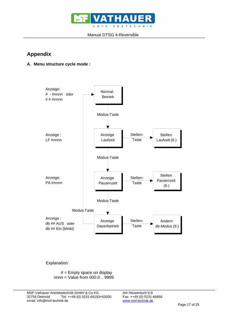
A. Menu structure cycle mode :
Anzeige Dauerbetrieb
Stellen-Taste
Stellen-Taste
Stellen-Taste
Modus-Taste
Modus-Taste
Modus-Taste
Modus-Taste
Normal- Betrieb
Anzeige Laufzeit
Anzeige Pausenzeit
Anzeige:# - #nnnn oder# # #nnnn
Anzeige :LF #nnnn
Anzeige:PA #nnnn
Anzeige :db ## AUS oderdb ## Ein (blinkt)
Stellen Laufzeit (6.)
Stellen Pausenzeit
(6.)
Ändern db-Modus (9.)
Explanation: # = Empty space on display nnnn = Value from 000.0 .. 9999

Manual DTSG 4-Reversible
MSF-Vathauer Antriebstechnik GmbH & Co KG Am Hessentuch 6-8 32758 Detmold Tel: ++49 (0) 5231-66193+63030 Fax: ++49 (0) 5231-66856 email: [email protected] www.msf-technik.de Page 18 of 25
B. Menu structure switching mode:
Modus-Taste
nur wenn SI ~ ~ ~ -
Modus-Taste
Modus-Taste
Stellen-Taste
Stellen-Taste
Stellen-Taste
Modus-Taste
Modus-Taste
Stellen-Taste
Stellen-Taste
Normal-Betrieb
Anzeige Pausenzeit
Trigger-Simulation
Stellen Pausenzeit
(6.)
Anzeige Trigger-Modus
Ändern Trigger-Modus
(7.)
AnzeigeImpuls-Unter-drückungszeit
Stellen der
Impuls-Unter-
drückungszeit (8.)
Anzeige : # - - - - - oder# # nnnn
Anzeige : PA #nnnn
Anzeige :SI # ~ ~ ~ - oderSI # ~ - - -
Anzeige :IL # nnnn
DauerbetriebAnzeige :db ## AUS oderdb ## Ein (blinkt)
Änderndb-Modus (9.)
Explanation: # = Empty space on display nnnn = Value 000.0 .. 9999.
Manual DTSG 4-Reversible
MSF-Vathauer Antriebstechnik GmbH & Co KG Am Hessentuch 6-8 32758 Detmold Tel: ++49 (0) 5231-66193+63030 Fax: ++49 (0) 5231-66856 email: [email protected] www.msf-technik.de Page 19 of 25
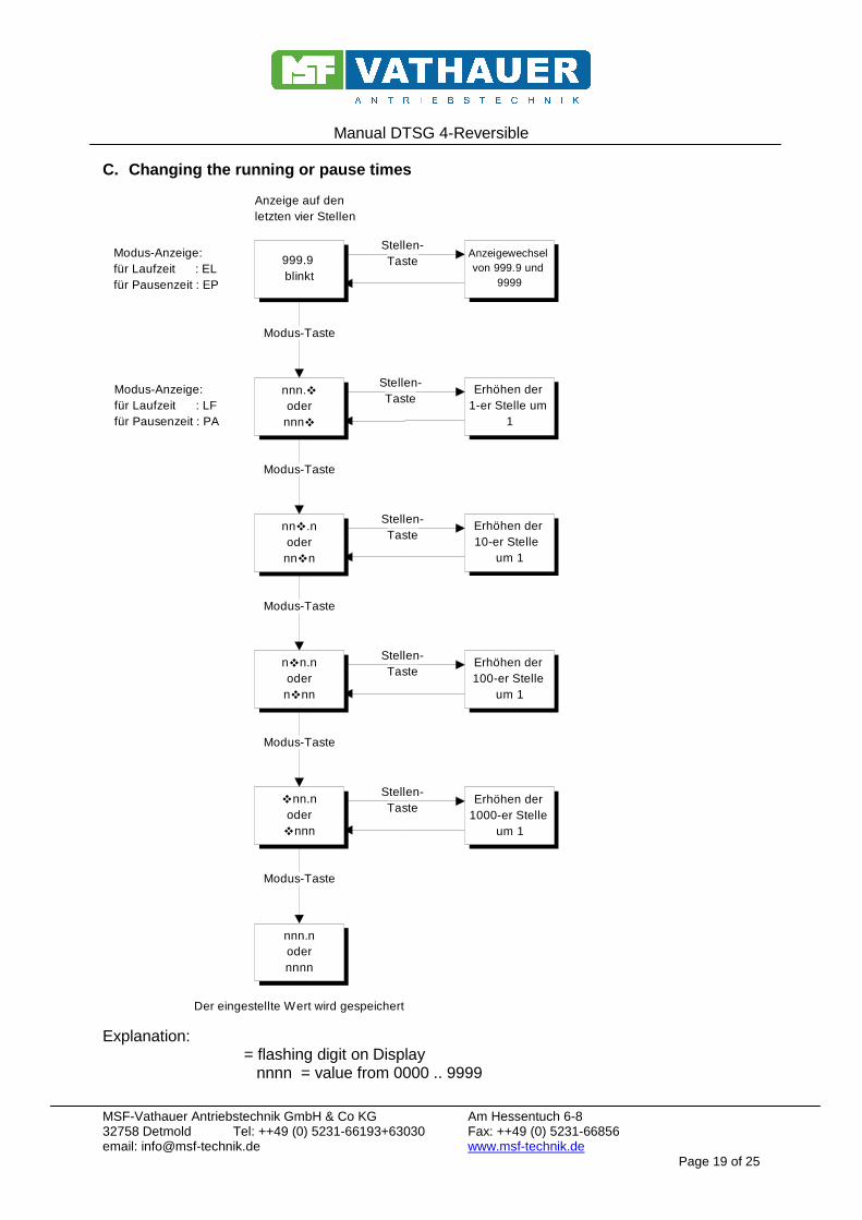
C. Changing the running or pause times
Stellen-Taste
Stellen-Taste
Stellen-Taste
Stellen-Taste
Stellen-Taste
Modus-Taste
Modus-Taste
Modus-Taste
Modus-Taste
Modus-Taste
999.9 blinkt
nnn.�odernnn�
nn�.nodernn�n
n�n.nodern�nn
�nn.noder�nnn
nnn.nodernnnn
Erhöhen der 1-er Stelle um
1
Erhöhen der 10-er Stelle
um 1
Erhöhen der 100-er Stelle
um 1
Erhöhen der 1000-er Stelle
um 1
Anzeigewechsel von 999.9 und
9999
Modus-Anzeige:für Laufzeit : ELfür Pausenzeit : EP
Modus-Anzeige:für Laufzeit : LFfür Pausenzeit : PA
Anzeige auf denletzten vier Stellen
Der eingestellte Wert wird gespeichert
Explanation: � = flashing digit on Display nnnn = value from 0000 .. 9999

Manual DTSG 4-Reversible
MSF-Vathauer Antriebstechnik GmbH & Co KG Am Hessentuch 6-8 32758 Detmold Tel: ++49 (0) 5231-66193+63030 Fax: ++49 (0) 5231-66856 email: [email protected] www.msf-technik.de Page 20 of 25
D. Setting the Trigger Mode
Stellen-Taste
Modus-Taste
~ - - -oder
~ ~ ~ -
~ - - -oder
~ ~ ~ -
Anzeige auf den letzten vier Stellen (blinkend)
Modus-Anzeige : SIModus-
Wechsel
Anzeige blinkt nicht mehr,Modus wird gespeichert
Explanation: � = flashing digit on Display nnnn = value from 0000 .. 9999

Manual DTSG 4-Reversible
MSF-Vathauer Antriebstechnik GmbH & Co KG Am Hessentuch 6-8 32758 Detmold Tel: ++49 (0) 5231-66193+63030 Fax: ++49 (0) 5231-66856 email: [email protected] www.msf-technik.de Page 21 of 25
E. Setting the time for suppressed impulse
Stellen-Taste
Stellen-Taste
Stellen-Taste
Stellen-Taste
Modus-Taste
Modus-Taste
Modus-Taste
Modus-Taste
n.nn�
n.n�n
n.�nn
�.nnn
n.nnn
Erhöhen der 1/1000- Stelle
um 1
Erhöhen der 1/100-Stelle
um 1
Erhöhen der 1/100 Stelle
um 1
Erhöhen der 1-er Stelle um
1
Der eingestellte Wert wird gespeichert
Zeit-Anzeige
Modus-Anzeige : IL
Explanation:

Manual DTSG 4-Reversible
MSF-Vathauer Antriebstechnik GmbH & Co KG Am Hessentuch 6-8 32758 Detmold Tel: ++49 (0) 5231-66193+63030 Fax: ++49 (0) 5231-66856 email: [email protected] www.msf-technik.de Page 22 of 25
� = Fashing digit on display nnnn = value 0000 .. 9999
F. Assignment of terminals
Pin-No. Signal Note 1 N.C,
2 L1
3 N.C.
4 L2
5 N.C.
6 L3 Voltage supply for the logic
7 N Voltage supply for the logic
8 PE
9 0V
10 Relay, Output 1 Can be used as opener or closer when used with
Pin 11
11 Relay, Output 2
12 External Trigger- Impulse External start impulse (Trigger) (only switching operation, ext. trigger) 24V (from pin 16) from this terminal starts the motor
13 Error input
For thermal contact from motor pin 15 must be connected open = error
14 Configuration „External Trigger“ (also see 3.2)
Enables switch mode when connected to pin 9 (OV)
15 +24V + 24 V, unstable max. 29,5 V
16 +24V + 24 V, unstable max. 29,5 V
17 +24V + 24 V, unstable max. 29,5 V
18 0V
19 Input photoelectric cell Photoelectric-cell belt. end (NPN / PNP is adjustable with Jumper J7)
20 Input photoelectric cell Input for pulse "conveyor belt return" (NPN / PNP is adjustable with Jumper J6)

Manual DTSG 4-Reversible
MSF-Vathauer Antriebstechnik GmbH & Co KG Am Hessentuch 6-8 32758 Detmold Tel: ++49 (0) 5231-66193+63030 Fax: ++49 (0) 5231-66856 email: [email protected] www.msf-technik.de Page 23 of 25
21 U Switched motor phase conveyor belt
22 V Switched motor phase conveyor belt
23 W Switched motor phase conveyor belt
24 PE PE for conveyor motor
25 +24V PE for conveyor motor
26 Clearing Switch
Input for Clearing Switch
35 Relay Relay Output for Error
36 Relay Relay Output for Error
Note: A conveyor belt must not be connected to terminals 1 – 8!!
G. Assignment of the Sub-D socket Situated at the front is a 9-pol. Sub-D-Socket, which has in- and outputs to the control: Pin-Nr. Signal Remarks
1 ext. Trigger External start impulse (+24 Volt starts Trigger)
2 n.c.
3 OC GND Combined earth for OC-outputs
4 n.c.
5 Working Mode Working incl./ excl. ext. Trigger (Trigger, connected with PIN 9)
6 + 24V for ext. Trigger
7 Signal „Motor stop“ Open-Collector (OC)Output
8 Signal „Motor runs“ Open Collector (OC) Output
9 GND for code working mode

Manual DTSG 4-Reversible
MSF-Vathauer Antriebstechnik GmbH & Co KG Am Hessentuch 6-8 32758 Detmold Tel: ++49 (0) 5231-66193+63030 Fax: ++49 (0) 5231-66856 email: [email protected] www.msf-technik.de Page 24 of 25
H. Jumper connection For all Jumper: white dot = Pin 1 J4 Output relay J1 (Working mode) 1-2 Relay Output as opener Open: Code by Pin /Sub- D 2-3 Relay Output as Closer Bridged: Working with ext. Trigger
J2,J3 (Output - Relay- Mode) J5 (Recognition of position) J2/2-3 and J3/1-2: Relay switches in cycles Open: „upside down“position J2/1-2 and J3/2-3: Relay switches at motor fault 1-2: automatic recognition of
position 2-3: normal position J6,J7 (photoelectric-cell-type) Jumper to PIC: PNP- Type PNP- Type NPN- Type Jumper to front plate: NPN- Type

Manual DTSG 4-Reversible
MSF-Vathauer Antriebstechnik GmbH & Co KG Am Hessentuch 6-8 32758 Detmold Tel: ++49 (0) 5231-66193+63030 Fax: ++49 (0) 5231-66856 email: [email protected] www.msf-technik.de Page 25 of 25
I. Displays and error messages Possible displays at the DTSG (except of the normal operating displays as described before) are: rEL x.xx Shows the software version
x.xx is place holder for a digit e.g. 2.02 The number may be requested by pushing the two keys and switching on the device.
FEHLEr Error input (clamp 13) opened (see Appendix F).
The device sets the normal operation and may only set back by switching off and on again.
d-Error Internal data error.
The internally stored data are not valid or are interpreted as invalid (Check sum error). The device must be switched off and initialized. (Initialization: Push the Set button at the off device and switch on the device. The display shows „rESEt“ – release the Set button and push „Modus“ --> the version number appears, the device is initialized with default values and is ready for operation after another switching off-on).
Related Documents