SERVICE MANUAL USE Screw Compressor Model: SK 26 GL---Nr.: BA---SK26.L---1.9763.50210---00 03 L Volt L Cabinet heaters .......................... L Wye---Delta Start L 115 V receptacle L D.O.L. Start L Outdoor modification L psig L Rainhoods .......................... L L Switchable Modulation ............................. L L Synthetic lubricant ............................. ................... L Wiring Diagram: L Food Grade lubricant ................. .............................. Serial No.: ...............................................

Manual compressor
Nov 27, 2015
SK26 TBA 1_9763_50210-00_03USE
Welcome message from author
This document is posted to help you gain knowledge. Please leave a comment to let me know what you think about it! Share it to your friends and learn new things together.
Transcript
SERVICE MANUALUSE
Screw Compressor
Model: SK 26GL---Nr.: BA---SK26.L---1.9763.50210---00 03
L Volt L Cabinet heaters. . . . . . . . . . . . . . . . . . . . . . . . . .
L Wye---Delta Start L 115 V receptacle
L D.O.L. Start L Outdoor modification
L psig L Rainhoods. . . . . . . . . . . . . . . . . . . . . . . . . .
L L Switchable Modulation. . . . . . . . . . . . . . . . . . . . . . . . . . . . .
L L Synthetic lubricant. . . . . . . . . . . . . . . . . . . . . . . . . . . . . . . . . . . . . . . . . . . . . . . .
L Wiring Diagram: L Food Grade lubricant . . . . . . . . . . . . . . . . .
. . . . . . . . . . . . . . . . . . . . . . . . . . . . . .
Serial No.: ...............................................

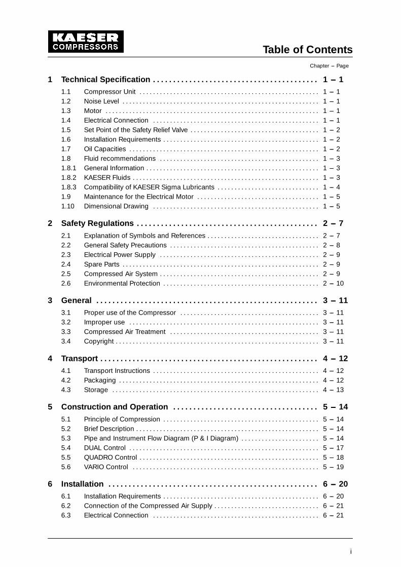
Table of ContentsChapter --- Page
i
1 Technical Specification 1 --- 1. . . . . . . . . . . . . . . . . . . . . . . . . . . . . . . . . . . . . . . . .1.1 Compressor Unit 1 --- 1. . . . . . . . . . . . . . . . . . . . . . . . . . . . . . . . . . . . . . . . . . . . . . . . . . . . .1.2 Noise Level 1 --- 1. . . . . . . . . . . . . . . . . . . . . . . . . . . . . . . . . . . . . . . . . . . . . . . . . . . . . . . . . .1.3 Motor 1 --- 1. . . . . . . . . . . . . . . . . . . . . . . . . . . . . . . . . . . . . . . . . . . . . . . . . . . . . . . . . . . . . . .1.4 Electrical Connection 1 --- 1. . . . . . . . . . . . . . . . . . . . . . . . . . . . . . . . . . . . . . . . . . . . . . . . .1.5 Set Point of the Safety Relief Valve 1 --- 2. . . . . . . . . . . . . . . . . . . . . . . . . . . . . . . . . . . . . .1.6 Installation Requirements 1 --- 2. . . . . . . . . . . . . . . . . . . . . . . . . . . . . . . . . . . . . . . . . . . . . .1.7 Oil Capacities 1 --- 2. . . . . . . . . . . . . . . . . . . . . . . . . . . . . . . . . . . . . . . . . . . . . . . . . . . . . . . .1.8 Fluid recommendations 1 --- 3. . . . . . . . . . . . . . . . . . . . . . . . . . . . . . . . . . . . . . . . . . . . . . .1.8.1 General Information 1 --- 3. . . . . . . . . . . . . . . . . . . . . . . . . . . . . . . . . . . . . . . . . . . . . . . . . . .1.8.2 KAESER Fluids 1 --- 3. . . . . . . . . . . . . . . . . . . . . . . . . . . . . . . . . . . . . . . . . . . . . . . . . . . . . . .1.8.3 Compatibility of KAESER Sigma Lubricants 1 --- 4. . . . . . . . . . . . . . . . . . . . . . . . . . . . . .1.9 Maintenance for the Electrical Motor 1 --- 5. . . . . . . . . . . . . . . . . . . . . . . . . . . . . . . . . . . .1.10 Dimensional Drawing 1 --- 5. . . . . . . . . . . . . . . . . . . . . . . . . . . . . . . . . . . . . . . . . . . . . . . . .
2 Safety Regulations 2 --- 7. . . . . . . . . . . . . . . . . . . . . . . . . . . . . . . . . . . . . . . . . . . . .2.1 Explanation of Symbols and References 2 --- 7. . . . . . . . . . . . . . . . . . . . . . . . . . . . . . . . .2.2 General Safety Precautions 2 --- 8. . . . . . . . . . . . . . . . . . . . . . . . . . . . . . . . . . . . . . . . . . . .2.3 Electrical Power Supply 2 --- 9. . . . . . . . . . . . . . . . . . . . . . . . . . . . . . . . . . . . . . . . . . . . . . .2.4 Spare Parts 2 --- 9. . . . . . . . . . . . . . . . . . . . . . . . . . . . . . . . . . . . . . . . . . . . . . . . . . . . . . . . . .2.5 Compressed Air System 2 --- 9. . . . . . . . . . . . . . . . . . . . . . . . . . . . . . . . . . . . . . . . . . . . . . .2.6 Environmental Protection 2 --- 10. . . . . . . . . . . . . . . . . . . . . . . . . . . . . . . . . . . . . . . . . . . . . .
3 General 3 --- 11. . . . . . . . . . . . . . . . . . . . . . . . . . . . . . . . . . . . . . . . . . . . . . . . . . . . . . .3.1 Proper use of the Compressor 3 --- 11. . . . . . . . . . . . . . . . . . . . . . . . . . . . . . . . . . . . . . . . .3.2 Improper use 3 --- 11. . . . . . . . . . . . . . . . . . . . . . . . . . . . . . . . . . . . . . . . . . . . . . . . . . . . . . . .3.3 Compressed Air Treatment 3 --- 11. . . . . . . . . . . . . . . . . . . . . . . . . . . . . . . . . . . . . . . . . . . .3.4 Copyright 3 --- 11. . . . . . . . . . . . . . . . . . . . . . . . . . . . . . . . . . . . . . . . . . . . . . . . . . . . . . . . . . . .
4 Transport 4 --- 12. . . . . . . . . . . . . . . . . . . . . . . . . . . . . . . . . . . . . . . . . . . . . . . . . . . . . .4.1 Transport Instructions 4 --- 12. . . . . . . . . . . . . . . . . . . . . . . . . . . . . . . . . . . . . . . . . . . . . . . . .4.2 Packaging 4 --- 12. . . . . . . . . . . . . . . . . . . . . . . . . . . . . . . . . . . . . . . . . . . . . . . . . . . . . . . . . . .4.3 Storage 4 --- 13. . . . . . . . . . . . . . . . . . . . . . . . . . . . . . . . . . . . . . . . . . . . . . . . . . . . . . . . . . . . .
5 Construction and Operation 5 --- 14. . . . . . . . . . . . . . . . . . . . . . . . . . . . . . . . . . . .5.1 Principle of Compression 5 --- 14. . . . . . . . . . . . . . . . . . . . . . . . . . . . . . . . . . . . . . . . . . . . . .5.2 Brief Description 5 --- 14. . . . . . . . . . . . . . . . . . . . . . . . . . . . . . . . . . . . . . . . . . . . . . . . . . . . . .5.3 Pipe and Instrument Flow Diagram (P & I Diagram) 5 --- 14. . . . . . . . . . . . . . . . . . . . . . .5.4 DUAL Control 5 --- 17. . . . . . . . . . . . . . . . . . . . . . . . . . . . . . . . . . . . . . . . . . . . . . . . . . . . . . . .5.5 QUADRO Control 5 --- 18. . . . . . . . . . . . . . . . . . . . . . . . . . . . . . . . . . . . . . . . . . . . . . . . . . . . .5.6 VARIO Control 5 --- 19. . . . . . . . . . . . . . . . . . . . . . . . . . . . . . . . . . . . . . . . . . . . . . . . . . . . . . .
6 Installation 6 --- 20. . . . . . . . . . . . . . . . . . . . . . . . . . . . . . . . . . . . . . . . . . . . . . . . . . . .6.1 Installation Requirements 6 --- 20. . . . . . . . . . . . . . . . . . . . . . . . . . . . . . . . . . . . . . . . . . . . . .6.2 Connection of the Compressed Air Supply 6 --- 21. . . . . . . . . . . . . . . . . . . . . . . . . . . . . . .6.3 Electrical Connection 6 --- 21. . . . . . . . . . . . . . . . . . . . . . . . . . . . . . . . . . . . . . . . . . . . . . . . .
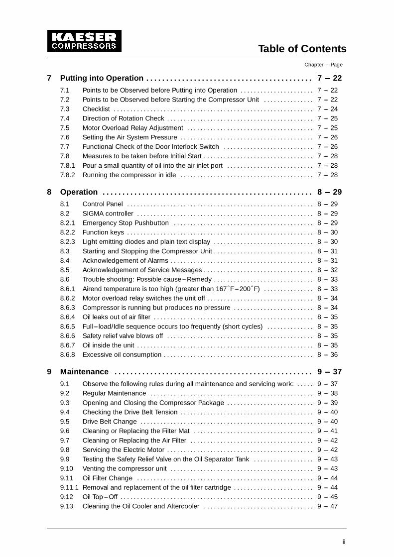
Table of ContentsChapter --- Page
ii
7 Putting into Operation 7 --- 22. . . . . . . . . . . . . . . . . . . . . . . . . . . . . . . . . . . . . . . . . .7.1 Points to be Observed before Putting into Operation 7 --- 22. . . . . . . . . . . . . . . . . . . . . .7.2 Points to be Observed before Starting the Compressor Unit 7 --- 22. . . . . . . . . . . . . . .7.3 Checklist 7 --- 24. . . . . . . . . . . . . . . . . . . . . . . . . . . . . . . . . . . . . . . . . . . . . . . . . . . . . . . . . . . .7.4 Direction of Rotation Check 7 --- 25. . . . . . . . . . . . . . . . . . . . . . . . . . . . . . . . . . . . . . . . . . . .7.5 Motor Overload Relay Adjustment 7 --- 25. . . . . . . . . . . . . . . . . . . . . . . . . . . . . . . . . . . . . .7.6 Setting the Air System Pressure 7 --- 26. . . . . . . . . . . . . . . . . . . . . . . . . . . . . . . . . . . . . . . .7.7 Functional Check of the Door Interlock Switch 7 --- 26. . . . . . . . . . . . . . . . . . . . . . . . . . .7.8 Measures to be taken before Initial Start 7 --- 28. . . . . . . . . . . . . . . . . . . . . . . . . . . . . . . . .7.8.1 Pour a small quantity of oil into the air inlet port 7 --- 28. . . . . . . . . . . . . . . . . . . . . . . . . .7.8.2 Running the compressor in idle 7 --- 28. . . . . . . . . . . . . . . . . . . . . . . . . . . . . . . . . . . . . . . .
8 Operation 8 --- 29. . . . . . . . . . . . . . . . . . . . . . . . . . . . . . . . . . . . . . . . . . . . . . . . . . . . .8.1 Control Panel 8 --- 29. . . . . . . . . . . . . . . . . . . . . . . . . . . . . . . . . . . . . . . . . . . . . . . . . . . . . . . .8.2 SIGMA controller 8 --- 29. . . . . . . . . . . . . . . . . . . . . . . . . . . . . . . . . . . . . . . . . . . . . . . . . . . . .8.2.1 Emergency Stop Pushbutton 8 --- 29. . . . . . . . . . . . . . . . . . . . . . . . . . . . . . . . . . . . . . . . . .8.2.2 Function keys 8 --- 30. . . . . . . . . . . . . . . . . . . . . . . . . . . . . . . . . . . . . . . . . . . . . . . . . . . . . . . .8.2.3 Light emitting diodes and plain text display 8 --- 30. . . . . . . . . . . . . . . . . . . . . . . . . . . . . .8.3 Starting and Stopping the Compressor Unit 8 --- 31. . . . . . . . . . . . . . . . . . . . . . . . . . . . . .8.4 Acknowledgement of Alarms 8 --- 31. . . . . . . . . . . . . . . . . . . . . . . . . . . . . . . . . . . . . . . . . . .8.5 Acknowledgement of Service Messages 8 --- 32. . . . . . . . . . . . . . . . . . . . . . . . . . . . . . . . .8.6 Trouble shooting: Possible cause---Remedy 8 --- 33. . . . . . . . . . . . . . . . . . . . . . . . . . . . . .8.6.1 Airend temperature is too high (greater than 167�F---200�F) 8 --- 33. . . . . . . . . . . . . . .8.6.2 Motor overload relay switches the unit off 8 --- 34. . . . . . . . . . . . . . . . . . . . . . . . . . . . . . . .8.6.3 Compressor is running but produces no pressure 8 --- 34. . . . . . . . . . . . . . . . . . . . . . . .8.6.4 Oil leaks out of air filter 8 --- 35. . . . . . . . . . . . . . . . . . . . . . . . . . . . . . . . . . . . . . . . . . . . . . . .8.6.5 Full---load/Idle sequence occurs too frequently (short cycles) 8 --- 35. . . . . . . . . . . . . .8.6.6 Safety relief valve blows off 8 --- 35. . . . . . . . . . . . . . . . . . . . . . . . . . . . . . . . . . . . . . . . . . . .8.6.7 Oil inside the unit 8 --- 35. . . . . . . . . . . . . . . . . . . . . . . . . . . . . . . . . . . . . . . . . . . . . . . . . . . . .8.6.8 Excessive oil consumption 8 --- 36. . . . . . . . . . . . . . . . . . . . . . . . . . . . . . . . . . . . . . . . . . . . .
9 Maintenance 9 --- 37. . . . . . . . . . . . . . . . . . . . . . . . . . . . . . . . . . . . . . . . . . . . . . . . . .9.1 Observe the following rules during all maintenance and servicing work: 9 --- 37. . . . .9.2 Regular Maintenance 9 --- 38. . . . . . . . . . . . . . . . . . . . . . . . . . . . . . . . . . . . . . . . . . . . . . . . .9.3 Opening and Closing the Compressor Package 9 --- 39. . . . . . . . . . . . . . . . . . . . . . . . . .9.4 Checking the Drive Belt Tension 9 --- 40. . . . . . . . . . . . . . . . . . . . . . . . . . . . . . . . . . . . . . . .9.5 Drive Belt Change 9 --- 40. . . . . . . . . . . . . . . . . . . . . . . . . . . . . . . . . . . . . . . . . . . . . . . . . . . .9.6 Cleaning or Replacing the Filter Mat 9 --- 41. . . . . . . . . . . . . . . . . . . . . . . . . . . . . . . . . . . .9.7 Cleaning or Replacing the Air Filter 9 --- 42. . . . . . . . . . . . . . . . . . . . . . . . . . . . . . . . . . . . .9.8 Servicing the Electric Motor 9 --- 42. . . . . . . . . . . . . . . . . . . . . . . . . . . . . . . . . . . . . . . . . . . .9.9 Testing the Safety Relief Valve on the Oil Separator Tank 9 --- 43. . . . . . . . . . . . . . . . . .9.10 Venting the compressor unit 9 --- 43. . . . . . . . . . . . . . . . . . . . . . . . . . . . . . . . . . . . . . . . . . .9.11 Oil Filter Change 9 --- 44. . . . . . . . . . . . . . . . . . . . . . . . . . . . . . . . . . . . . . . . . . . . . . . . . . . . .9.11.1 Removal and replacement of the oil filter cartridge 9 --- 44. . . . . . . . . . . . . . . . . . . . . . . .9.12 Oil Top ---Off 9 --- 45. . . . . . . . . . . . . . . . . . . . . . . . . . . . . . . . . . . . . . . . . . . . . . . . . . . . . . . . . .9.13 Cleaning the Oil Cooler and Aftercooler 9 --- 47. . . . . . . . . . . . . . . . . . . . . . . . . . . . . . . . .
Table of ContentsChapter --- Page
iii
9.13.1 Removing and cleaning the oil cooler/air aftercooler 9 --- 47. . . . . . . . . . . . . . . . . . . . . .9.14 Oil Change (Oil Separator Tank and Oil Cooler) 9 --- 48. . . . . . . . . . . . . . . . . . . . . . . . . .9.14.1 Oil change using external pressure source 9 --- 50. . . . . . . . . . . . . . . . . . . . . . . . . . . . . .9.14.2 Oil top ---off 9 --- 51. . . . . . . . . . . . . . . . . . . . . . . . . . . . . . . . . . . . . . . . . . . . . . . . . . . . . . . . . . .9.14.3 Draining the oil using own compressed air 9 --- 51. . . . . . . . . . . . . . . . . . . . . . . . . . . . . . .9.14.4 Procedure for putting back into operation 9 --- 52. . . . . . . . . . . . . . . . . . . . . . . . . . . . . . .9.15 Changing the Oil Separator Cartridge 9 --- 52. . . . . . . . . . . . . . . . . . . . . . . . . . . . . . . . . . .9.16 Maintenance Schedule 9 --- 55. . . . . . . . . . . . . . . . . . . . . . . . . . . . . . . . . . . . . . . . . . . . . . . .
10 Spare Parts and After Sales Service 10 --- 56. . . . . . . . . . . . . . . . . . . . . . . . . . . . .
10.1 Service parts and maintenance parts 10 --- 56. . . . . . . . . . . . . . . . . . . . . . . . . . . . . . . . . . .10.2 Service and Maintenance Agreement 10 --- 57. . . . . . . . . . . . . . . . . . . . . . . . . . . . . . . . . . .
11 Appendix 11 --- 58. . . . . . . . . . . . . . . . . . . . . . . . . . . . . . . . . . . . . . . . . . . . . . . . . . . . . .
11.1 Wiring Diagram 11 --- 58. . . . . . . . . . . . . . . . . . . . . . . . . . . . . . . . . . . . . . . . . . . . . . . . . . . . . .11.2 Spare Parts List 11 --- 75. . . . . . . . . . . . . . . . . . . . . . . . . . . . . . . . . . . . . . . . . . . . . . . . . . . . . .
Technical Specification
1 --- 1
1 Technical Specification
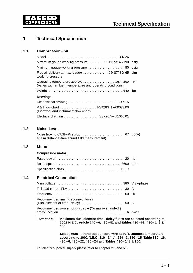
1.1 Compressor UnitModel SK 26. . . . . . . . . . . . . . . . . . . . . . . . . . . . . . . . . . . . . . . . . . .
Maximum gauge working pressure 110/125/145/190 psig. . . . . . . .
Minimum gauge working pressure 80 psig. . . . . . . . . . . . . . . . . . . . . .
Free air delivery at max. gauge 92/ 87/ 80/ 65 cfm. . . . . . . . . . . . . .working pressure
Operating temperature approx. 167---200 EF. . . . . . . . . . . . . . . . . . .(Varies with ambient temperature and operating conditions)
Weight 640 lbs. . . . . . . . . . . . . . . . . . . . . . . . . . . . . . . . . . . . . . . . . . . . .
Drawings:
Dimensional drawing T 7471.5. . . . . . . . . . . . . . . . . . . . . . . . . . . .
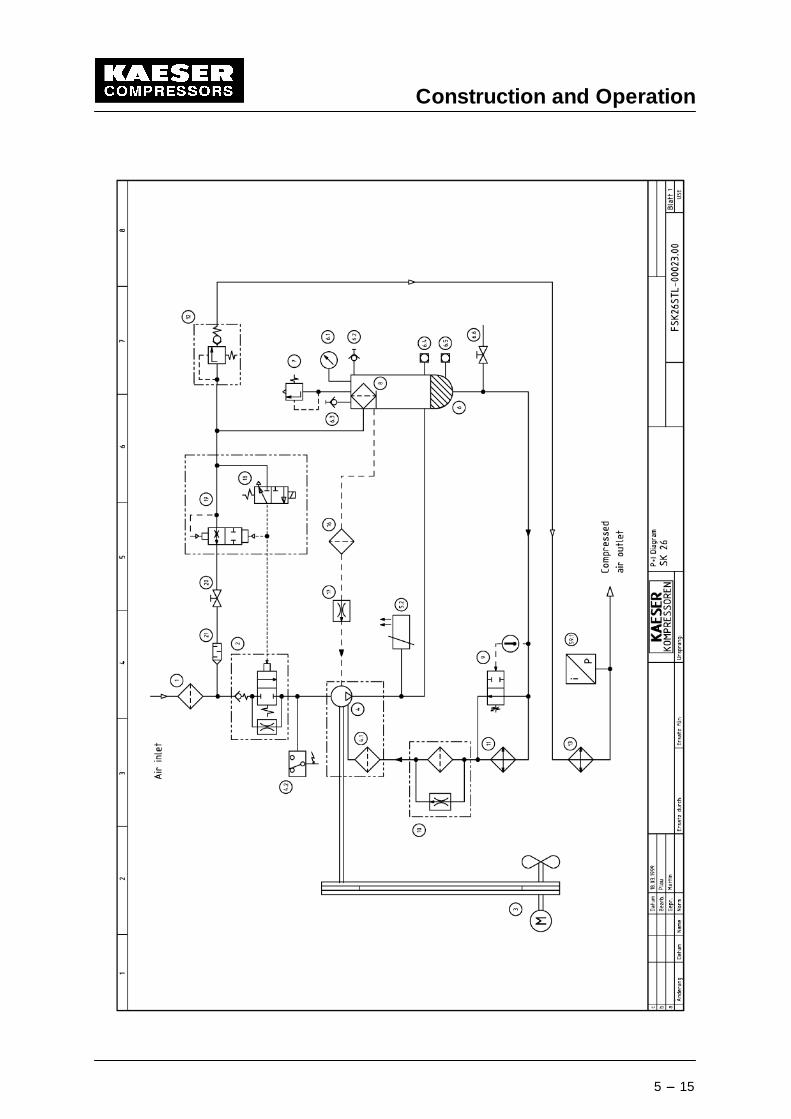
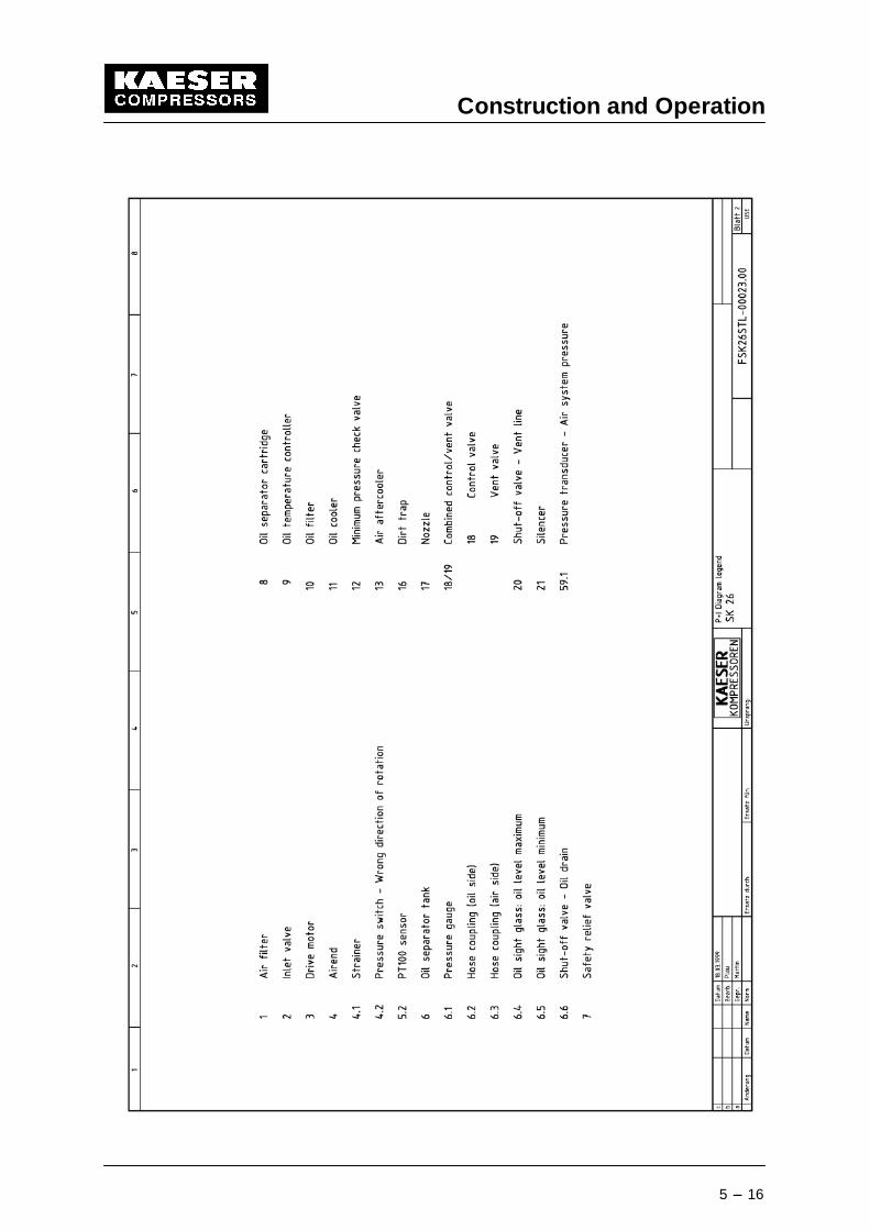
P & I flow chart FSK26STL---00023.00. . . . . . . . . . . . . . . . . . . . . .(Pipework and instrument flow chart)
Electrical diagram SSK26.Y---U1016.01. . . . . . . . . . . . . . . . . . . . .
1.2 Noise LevelNoise level to CAGI---Pneurop 67 dB(A). . . . . . . . . . . . . . . . . . . . . . . . . .at 1 m distance (free sound field measurement)
1.3 Motor
Compressor motor:
Rated power 20 hp. . . . . . . . . . . . . . . . . . . . . . . . . . . . . . . . . . . . . . . . .
Rated speed 3600 rpm. . . . . . . . . . . . . . . . . . . . . . . . . . . . . . . . . . . . . . .
Specification class TEFC. . . . . . . . . . . . . . . . . . . . . . . . . . . . . . . . .
1.4 Electrical ConnectionMain voltage 380 V 3---phase. . . . . . . . . . . . . . . . . . . . . . . . . . . . . . . . . . . . . . . .
Full load current FLA 30 A. . . . . . . . . . . . . . . . . . . . . . . . . . . . . . . . . .
Frequency 60 Hz. . . . . . . . . . . . . . . . . . . . . . . . . . . . . . . . . . . . . . . . . . .
Recommended main disconnect fuses(Dual element or time---delay) 50 A. . . . . . . . . . . . . . . . . . . . . . . . . .
Recommended power supply cable (Cu multi---stranded )cross---section 6 AWG. . . . . . . . . . . . . . . . . . . . . . . . . . . . . . . . . . . . . . . . .
Maximum dual element time--delay fuses are selected according to2002 N.E.C. Article 240--6, 430--52 and Tables 430--52, 430--148 &150.
Select multi--strand copper core wire at 40�C ambient temperatureaccording to 2002 N.E.C. 110--14(c), 220--3, 310--15, Table 310--16,430--6, 430--22, 430--24 and Tables 430--148 & 150.
For electrical power supply please refer to chapter 2.3 and 6.3
Attention!
Technical Specification
1 --- 2
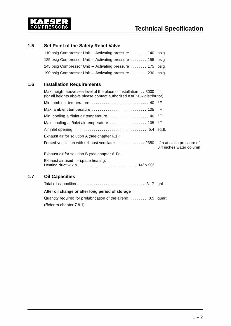
1.5 Set Point of the Safety Relief Valve
110 psig Compressor Unit --- Activating pressure 140 psig. . . . . . . .
125 psig Compressor Unit --- Activating pressure 155 psig. . . . . . . .
145 psig Compressor Unit --- Activating pressure 175 psig. . . . . . . .
190 psig Compressor Unit --- Activating pressure 230 psig. . . . . . . .
1.6 Installation Requirements
Max. height above sea level of the place of installation 3000 ft.. .(for all heights above please contact authorized KAESER distributor)
Min. ambient temperature 40 EF. . . . . . . . . . . . . . . . . . . . . . . . . . . . .
Max. ambient temperature 105 EF. . . . . . . . . . . . . . . . . . . . . . . . . . . .
Min. cooling air/inlet air temperature 40 EF. . . . . . . . . . . . . . . . . . . .
Max. cooling air/inlet air temperature 105 EF. . . . . . . . . . . . . . . . . . .
Air inlet opening 5.4 sq.ft.. . . . . . . . . . . . . . . . . . . . . . . . . . . . . . . . . . . . .
Exhaust air for solution A (see chapter 6.1):
Forced ventilation with exhaust ventilator 2350 cfm at static pressure of. . . . . . . . . . . . . .0.4 inches water column
Exhaust air for solution B (see chapter 6.1):
Exhaust air used for space heating:Heating duct w x h 14” x 20”. . . . . . . . . . . . . . . . . . . . . . . . . . . . . .
1.7 Oil Capacities
Total oil capacities 3.17 gal. . . . . . . . . . . . . . . . . . . . . . . . . . . . . . . . . .
After oil change or after long period of storage
Quantity required for prelubrication of the airend 0.5 quart. . . . . . . . .
(Refer to chapter 7.8.1)
Technical Specification
1 --- 3
1.8 Fluid recommendationsLubrication of an air compressor is essential to reliable operation. Carbon and varnish canform in compressor oils. These deposits block the flow of lubricant and cause excessivewear and failure of moving parts. Contamination of the fluid can allow the formation ofacids, causing extensive internal corrosion. Water may be condensed decreasing thefluid’s lubricity.
Fluid in rotary compressors does much more than lubricate. During the compression pro-cess, it acts as a sealant in the airend which is important for maximum efficiency. The fluidalso absorbs much of the heat of compression to cool the airend and reduce the tempera-ture of the compressed air. It’s not enough that a compressor fluid lubricates well, it muststand up to the heat, pressure and contaminants that are present in every air compressor.
1.8.1 General Information
KAESER synthetic lubricants should be stored in a protected location to prevent contami-nation. Do not re---use drums; flush and send to reconditioner.
Although the KAESER synthetic is not highly flammable, it will burn. While KAESER syn-thetic compressor oil is less flammable than equal viscosity mineral oils, it cannot be classi-fied as a fire---resistant fluid. It has a flash point above 460�F. Since the user has total con-trol over the conditions of the compressor lubricant, he assumes total responsibility for itssafe usage.
Material Safety Data Sheets are available for each lubricant from your KAESER authorizeddistributors.
Regardless of the lubricant selected, the KAESER Sigma lubricants will separate readilyfrom water. If condensate occurs it can easily be removed. Let the compressor sit so thatany water can drain back to the separator tank and separate to the bottom. See chap-ter 9.14 proper draining procedure.
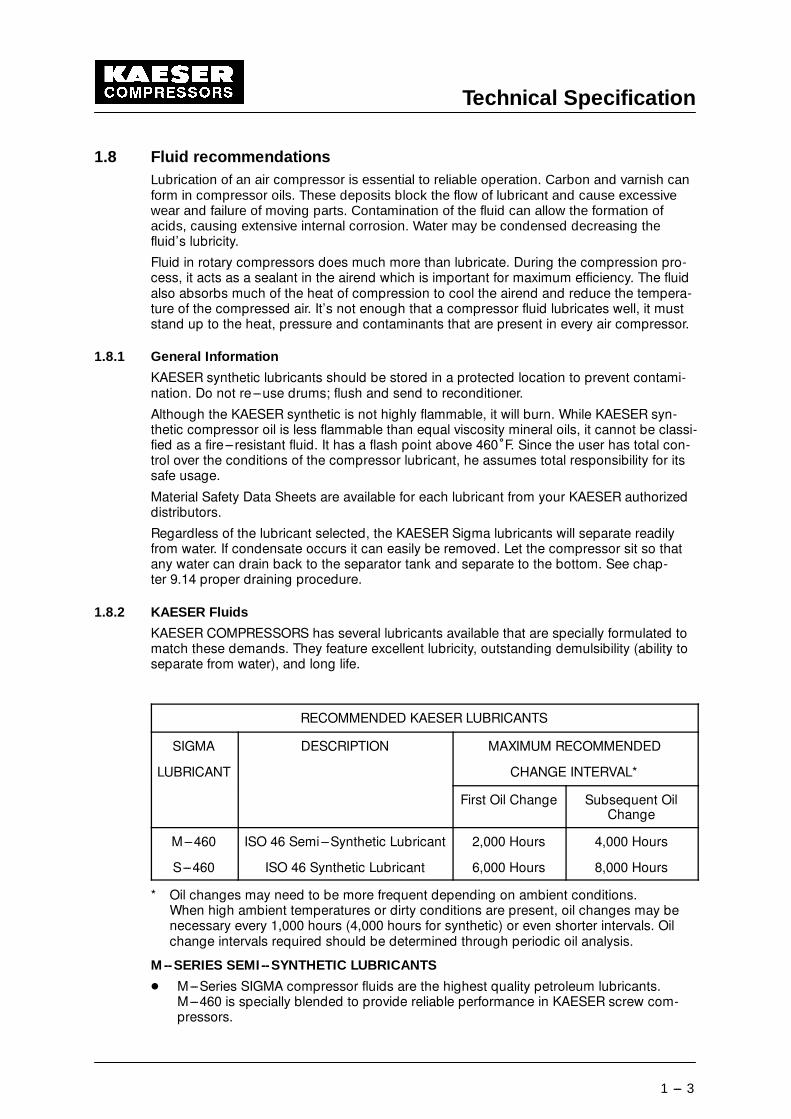
1.8.2 KAESER Fluids
KAESER COMPRESSORS has several lubricants available that are specially formulated tomatch these demands. They feature excellent lubricity, outstanding demulsibility (ability toseparate from water), and long life.
RECOMMENDED KAESER LUBRICANTS
SIGMA
LUBRICANT
DESCRIPTION MAXIMUM RECOMMENDED
CHANGE INTERVAL*
First Oil Change Subsequent OilChange
M---460
S---460
ISO 46 Semi---Synthetic Lubricant
ISO 46 Synthetic Lubricant
2,000 Hours
6,000 Hours
4,000 Hours
8,000 Hours
* Oil changes may need to be more frequent depending on ambient conditions.When high ambient temperatures or dirty conditions are present, oil changes may benecessary every 1,000 hours (4,000 hours for synthetic) or even shorter intervals. Oilchange intervals required should be determined through periodic oil analysis.
M --SERIES SEMI --SYNTHETIC LUBRICANTS
- M---Series SIGMA compressor fluids are the highest quality petroleum lubricants.M---460 is specially blended to provide reliable performance in KAESER screw com-pressors.
Technical Specification
1 --- 4
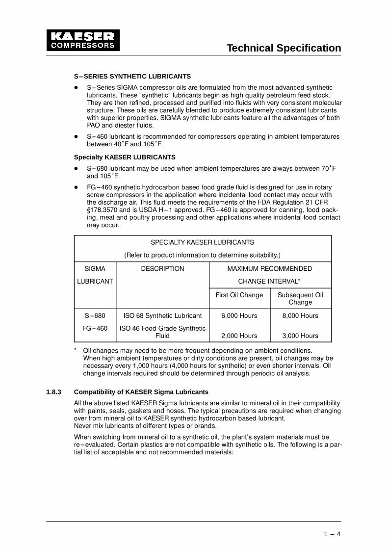
S--SERIES SYNTHETIC LUBRICANTS
- S---Series SIGMA compressor oils are formulated from the most advanced syntheticlubricants. These ”synthetic” lubricants begin as high quality petroleum feed stock.They are then refined, processed and purified into fluids with very consistent molecularstructure. These oils are carefully blended to produce extremely consistant lubricantswith superior properties. SIGMA synthetic lubricants feature all the advantages of bothPAO and diester fluids.
- S---460 lubricant is recommended for compressors operating in ambient temperaturesbetween 40�F and 105�F.
Specialty KAESER LUBRICANTS
- S---680 lubricant may be used when ambient temperatures are always between 70�Fand 105�F.
- FG---460 synthetic hydrocarbon based food grade fluid is designed for use in rotaryscrew compressors in the application where incidental food contact may occur withthe discharge air. This fluid meets the requirements of the FDA Regulation 21 CFR§178.3570 and is USDA H---1 approved. FG---460 is approved for canning, food pack-ing, meat and poultry processing and other applications where incidental food contactmay occur.
SPECIALTY KAESER LUBRICANTS
(Refer to product information to determine suitability.)
SIGMA
LUBRICANT
DESCRIPTION MAXIMUM RECOMMENDED
CHANGE INTERVAL*
First Oil Change Subsequent OilChange
S---680
FG---460
ISO 68 Synthetic Lubricant
ISO 46 Food Grade SyntheticFluid
6,000 Hours
2,000 Hours
8,000 Hours
3,000 Hours
* Oil changes may need to be more frequent depending on ambient conditions.When high ambient temperatures or dirty conditions are present, oil changes may benecessary every 1,000 hours (4,000 hours for synthetic) or even shorter intervals. Oilchange intervals required should be determined through periodic oil analysis.
1.8.3 Compatibility of KAESER Sigma Lubricants
All the above listed KAESER Sigma lubricants are similar to mineral oil in their compatibilitywith paints, seals, gaskets and hoses. The typical precautions are required when changingover from mineral oil to KAESER synthetic hydrocarbon based lubricant.Never mix lubricants of different types or brands.
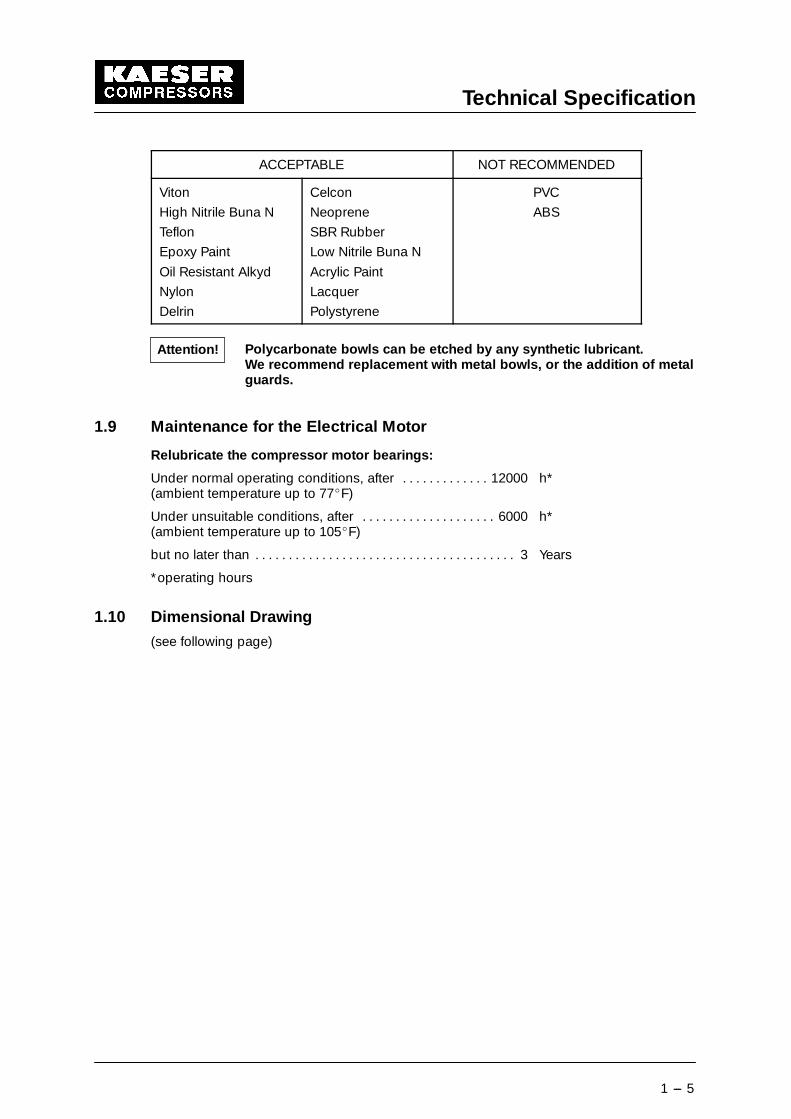
When switching from mineral oil to a synthetic oil, the plant’s system materials must bere---evaluated. Certain plastics are not compatible with synthetic oils. The following is a par-tial list of acceptable and not recommended materials:
Technical Specification
1 --- 5
ACCEPTABLE NOT RECOMMENDED
Viton
High Nitrile Buna N
Teflon
Epoxy Paint
Oil Resistant Alkyd
Nylon
Delrin
Celcon
Neoprene
SBR Rubber
Low Nitrile Buna N
Acrylic Paint
Lacquer
Polystyrene
PVC
ABS
Polycarbonate bowls can be etched by any synthetic lubricant.We recommend replacement with metal bowls, or the addition of metalguards.
1.9 Maintenance for the Electrical Motor
Relubricate the compressor motor bearings:
Under normal operating conditions, after 12000 h*. . . . . . . . . . . . .(ambient temperature up to 77EF)
Under unsuitable conditions, after 6000 h*. . . . . . . . . . . . . . . . . . . .(ambient temperature up to 105EF)
but no later than 3 Years. . . . . . . . . . . . . . . . . . . . . . . . . . . . . . . . . . . . . . .
*operating hours
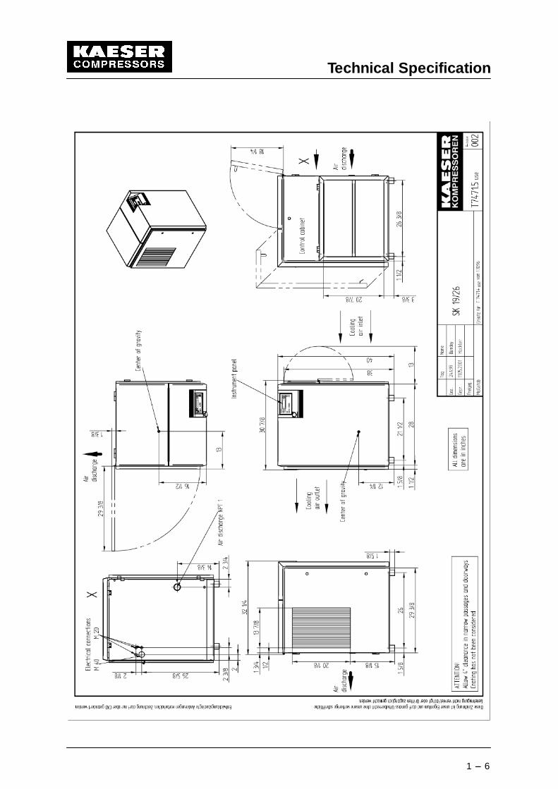
1.10 Dimensional Drawing
(see following page)
Attention!
Technical Specification
1 --- 6
Safety
2 --- 7
2 Safety Regulations
Read this service manual carefully and observe cautionary references before putting thiscompressor package into operation and before carrying out any maintenance.
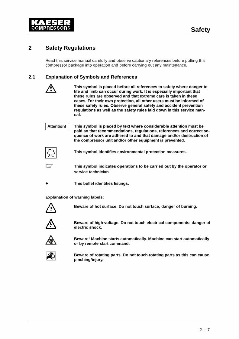
2.1 Explanation of Symbols and References
This symbol is placed before all references to safety where danger tolife and limb can occur during work. It is especially important thatthese rules are observed and that extreme care is taken in thesecases. For their own protection, all other users must be informed ofthese safety rules. Observe general safety and accident preventionregulations as well as the safety rules laid down in this service man-ual.
This symbol is placed by text where considerable attention must bepaid so that recommendations, regulations, references and correct se-quence of work are adhered to and that damage and/or destruction ofthe compressor unit and/or other equipment is prevented.
This symbol identifies environmental protection measures.
� This symbol indicates operations to be carried out by the operator orservice technician.
- This bullet identifies listings.
Explanation of warning labels:
Beware of hot surface. Do not touch surface; danger of burning.
Beware of high voltage. Do not touch electrical components; danger ofelectric shock.
Beware! Machine starts automatically. Machine can start automaticallyor by remote start command.
Beware of rotating parts. Do not touch rotating parts as this can causepinching/injury.
Attention!
Safety
2 --- 8
2.2 General Safety Precautions
Work on power driven systems may only be carried out by trained orspecialized personnel.
Work on the electrical equipment of the refrigerated dryer may only becarried out by a qualified electrician or trained personnel under thesupervision of a qualified electrician according to the NEC and any ap-plicable local codes.
Prior to working on electrical systems of the compressor always per-form the following steps in the sequence shown.
1. Lock the main disconnect in the ”off” position in accordance withapplicable lock out/ tag out procedures (example: OSHA CFR 29§ 1910.147) to ensure the compressor does not restart.
2. Ensure the package cannot be switched on again
3. Check that no voltage is present
4. Lock the isolation shut--off valve in the ”closed” position and ventall compressed air trapped between the compressor and the isolationshut--off valve in accordance with applicable lock out/ tag out pro-cedures (example: OSHA CFR 29 § 1910.147).
Unless the Service Manual states otherwise, all pressure lines must bevented or shut off.
Any alterations or reconstruction carried out without the prior writtenauthorization of KAESER COMPRESSORS Inc. will invalidate the war-ranty.
No welding, heat-- treatment or mechanical modifications may be car-ried out on pressurised components such as. pipework, air receivers,etc.
Safety devices may not be modified or deactivated.
Signs and labels of reference may not be removed or renderedunreadable.
These instructions must also be observed:
- Allow no open flames and flying sparks at the place of installation.
- Ensure that sparks or high temperatures cannot cause fire or explosion if welding iscarried out on or near the compressor.
- Ensure that the compressor unit can breathe clean intake air that contains no damag-ing components.
- Do not allow the maximum ambient temperature to be exceeded (see chapter 1.6),otherwise special measures must be agreed between the manufacturer and the cus-tomer.
Attention!
Attention!
Attention!
Safety
2 --- 9
- Carry out oil changes according to the service manual.
- Use only oils recommended by the manufacturer.
- Do not mix cooling oils of different types.
- The operating temperature stipulated must be kept to and checked constantly to avoidcondensate in the oil circulation.
- If maintenance work is carried out on any part of the oil circulation system, top up theoil in the oil separator tank to the maximum level afterwards, run the compressor for ashort period and keep it under constant observation. Check the oil level again and topup with oil to replace the oil taken up by the piping and the cooling system.
- Use the filter cartridge of the oil separator tank only as long as the pressure dropacross the filter is less than the 14.5 psi specified. Check constantly.
- This machine is not explosion---proof.It may not be operated in areas in which specific requirements with regard to ex-plosion protection are applied.
2.3 Electrical Power Supply
The main power supply and overcurrent protection must be installedby a qualified electrician in accordance with NEC, OSHA and any appli-cable local codes.
Compressor packages must be installed with a lockable main discon-nect and fuses or other short--circuit and ground fault protection de-vice.
For fuse and wire recommendations, see chapter 1.4
Please note that the conductors, fuses and procedure are KAESER’srecommendations. These recommendations do not supersede otherapplicable codes.
2.4 Spare Parts
Safe and reliable operation of the compressor package is guaranteed only with KAESERoriginal spare parts and KAESER SIGMA cooling oil.
Use only original parts in assemblies subject to pressure.
2.5 Compressed Air System
If a compressed air system is extended or changed, verify that the blowoff pressure andcapacities of the safety relief valves on the air receiver tanks and in the system match therating of all the compressor packages installed.
Attention!
Attention!
Safety
2 --- 10
2.6 Environmental Protection
Condensate drainage
The condensate accumulating during compression must be fed via asuitable drainage system, collected in special canisters and disposedof according to environmental regulations.
Maintenance materials/wear items/replacement parts
Ensure that all wear items, maintenance and replacement parts accu-mulating during operation of the compressor package are disposed ofaccording to environmental regulations.
The following points must be observed:
Avoid contact with skin and eyes.Do not inhale vapors and oil mist.Do not eat or drink when handling such materials.Fire, open flame and smoking are strictly forbidden.
General
3 --- 11
3 General
The service manual must always be available for use at the location ofthe compressor package.
The right is reserved to make technical changes and improvements to equipment whichmay then result in discrepencies in the details of that equipment contained in this manual.
3.1 Proper use of the Compressor
The compressor package is intended solely for the purpose of generating compressed air.Any further use outside of this purpose is considered improper. The manufacturer cannotaccept liability for any damage caused by such improper use; the user alone is liable forany risks incurred.Proper use of the compressor also includes adherence to the installation, removal, applica-tion, operational and maintenance instructions laid down by the manufacturer.
If the compressor package is operated in an air distribution network, the maximum networkpressure may not exceed 232 psig.
The equipment may only be used or serviced by authorized andtrained personnel.
3.2 Improper use
Never direct compressed air toward persons. Compressed air is a con-centrated form of energy and as such is dangerous to life.
Inlet air may not contain any explosive or chemically unstable gas orvapour.
3.3 Compressed Air Treatment
Never use compressed air from oil injected compressor packages forbreathing purposes and production methods where the air has directcontact with food, without subjecting the compressed air to additionaltreatment.
3.4 Copyright
KAESER COMPRESSORS, INC.
All rights reserved. No part of this manual may be reproduced in any form without per-mission of KAESER COMPRESSORS, INC.
Attention!
Attention!
Transport
4 --- 12
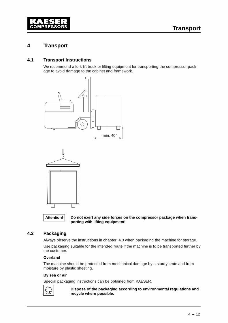
4 Transport
4.1 Transport InstructionsWe recommend a fork lift truck or lifting equipment for transporting the compressor pack-age to avoid damage to the cabinet and framework.
min. 40”
Do not exert any side forces on the compressor package when trans-porting with lifting equipment!
4.2 PackagingAlways observe the instructions in chapter 4.3 when packaging the machine for storage.
Use packaging suitable for the intended route if the machine is to be transported further bythe customer.
Overland
The machine should be protected from mechanical damage by a sturdy crate and frommoisture by plastic sheeting.
By sea or air
Special packaging instructions can be obtained from KAESER.
Dispose of the packaging according to environmental regulations andrecycle where possible.
Attention!
Transport
4 --- 13
4.3 Storage
If the equipment is to stand idle for a long period the prescribed measures must be takento avoid damage.
If any measures can not be taken, advice should be sought from an authorized KAESERdistribitor.
Basically, the equipment should be stored in a dry, frost-- free room.Protect against ingress of moisture or formation of condensation.See chapter 7.8 for instructions on start--up.
Storage up to 6 months (temporarily out of service):
As an alternative to storage, the equipment can be run once a week for 30 minutes at op-erating temperature to ensure adequate corrosion protection.Otherwise, the measures described under “’Storage for longer than 6 months’ are to betaken.
Storage for longer than 6 months:
Ensure the equipment is dry and cover in plastic sheeting. Protect the interior with suffi-cient quantities of desiccant (silica gel or similar).
Storage for longer than 12 months:
Carry out the following additional maintenance tasks before putting into operation:
� Change the oil filter (see chapter 9.11).
� Change the oil separator cartridge (see chapter 9.15).
� Change the oil (see chapter 9.14).
� Have the motor bearings checked by an authorized KAESER service technician.
Storage for longer than 3 years:
After 3 years at the latest the complete technical condition of the equipment must bechecked before start ---up.
Starting up the equipment without a full inspection can lead to dam-age.
� Have the the start ---up carried out by an authorized KAESER service technician.
Attention!
Attention!
Construction and Operation
5 --- 14
5 Construction and Operation
5.1 Principle of Compression
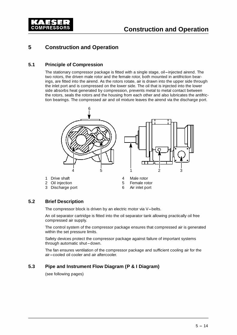
The stationary compressor package is fitted with a single stage, oil---injected airend. Thetwo rotors, the driven male rotor and the female rotor, both mounted in antifriction bear-ings, are fitted into the airend. As the rotors rotate, air is drawn into the upper side throughthe inlet port and is compressed on the lower side. The oil that is injected into the lowerside absorbs heat generated by compression, prevents metal to metal contact betweenthe rotors, seals the rotors and the housing from each other and also lubricates the antifric-tion bearings. The compressed air and oil mixture leaves the airend via the discharge port.
4 5
6
1 2 3
1 Drive shaft 4 Male rotor2 Oil injection 5 Female rotor3 Discharge port 6 Air inlet port
5.2 Brief Description
The compressor block is driven by an electric motor via V---belts.
An oil separator cartridge is fitted into the oil separator tank allowing practically oil freecompressed air supply.
The control system of the compressor package ensures that compressed air is generatedwithin the set pressure limits.
Safety devices protect the compressor package against failure of important systemsthrough automatic shut---down.
The fan ensures ventilation of the compressor package and sufficient cooling air for theair---cooled oil cooler and air aftercooler.
5.3 Pipe and Instrument Flow Diagram (P & I Diagram)
(see following pages)
Construction and Operation
5 --- 15
Construction and Operation
5 --- 16
Construction and Operation
5 --- 17
5.4 DUAL Control
pmaxp
min
Full load
StandstillMot
orp
ower
Pre
ssur
e
Time
t1 t2
1 2 3 4 5
Idle
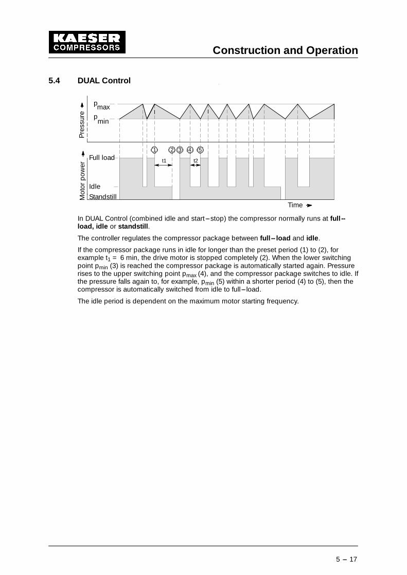
In DUAL Control (combined idle and start ---stop) the compressor normally runs at full --load, idle or standstill.
The controller regulates the compressor package between full -- load and idle.
If the compressor package runs in idle for longer than the preset period (1) to (2), forexample t1 = 6 min, the drive motor is stopped completely (2). When the lower switchingpoint pmin (3) is reached the compressor package is automatically started again. Pressurerises to the upper switching point pmax (4), and the compressor package switches to idle. Ifthe pressure falls again to, for example, pmin (5) within a shorter period (4) to (5), then thecompressor is automatically switched from idle to full---load.
The idle period is dependent on the maximum motor starting frequency.
Construction and Operation
5 --- 18
5.5 QUADRO Control
1
Full load
StandstillMot
orp
ower
Pre
ssur
e pmaxpmin
tprise
tpdecay
Running period
Idle/standstill period
Run---on period
1111Time
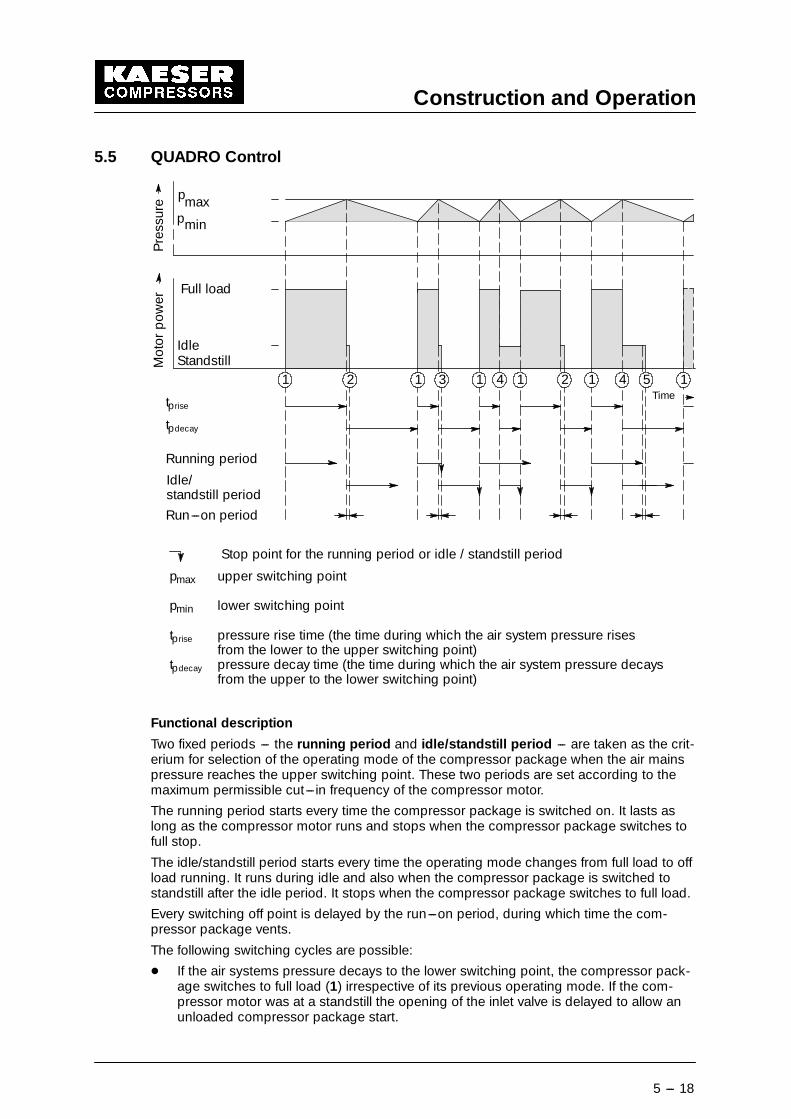
Stop point for the running period or idle / standstill period
132 24
pmax upper switching point
pmin lower switching point
tprise pressure rise time (the time during which the air system pressure risesfrom the lower to the upper switching point)
tpdecay pressure decay time (the time during which the air system pressure decaysfrom the upper to the lower switching point)
4 5 11
Idle
Functional description
Two fixed periods --- the running period and idle/standstill period --- are taken as the crit-erium for selection of the operating mode of the compressor package when the air mainspressure reaches the upper switching point. These two periods are set according to themaximum permissible cut---in frequency of the compressor motor.
The running period starts every time the compressor package is switched on. It lasts aslong as the compressor motor runs and stops when the compressor package switches tofull stop.
The idle/standstill period starts every time the operating mode changes from full load to offload running. It runs during idle and also when the compressor package is switched tostandstill after the idle period. It stops when the compressor package switches to full load.
Every switching off point is delayed by the run---on period, during which time the com-pressor package vents.
The following switching cycles are possible:
- If the air systems pressure decays to the lower switching point, the compressor pack-age switches to full load (1) irrespective of its previous operating mode. If the com-pressor motor was at a standstill the opening of the inlet valve is delayed to allow anunloaded compressor package start.
Construction and Operation
5 --- 19
- If the air systems pressure rises to the upper switching point and the running periodhas already expired, the compressor package is switched off after the run---on periodhas expired (2).
- If the air systems pressure rises to the upper switching point before the running periodhas expired then the pressure decay time of the previous switching cycle is taken asthe criterium for the selection of the operating mode:
-- If the pressure decay time tpdecay was longer than the period set for the idle/standstillperiod, the compressor is switched to standstill after the run---on period has ex-pired (3).
-- If the pressure decay time tpdecay was shorter than the period set for the idle / stand-still period, the idle mode is selected (4), that is, the inlet valve closes and the com-pressor is vented with running motor. When the running period expires the com-pressor package switches to standstill only after the run---on period has alsoexpired (5).
5.6 VARIO Control
Functional description:
The idle period is automatically lengthened or shortened by the variable idle control in rela-tion to the number of motor starts. The number of motor starts during the preceding hourare measured.
A high switching frequency leads to longer idle periods.A low switching frequency leads to shorter idle periods.
Installation
6 --- 20
6 Installation
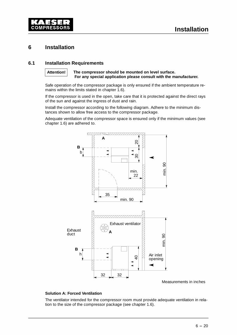
6.1 Installation Requirements
The compressor should be mounted on level surface.For any special application please consult with the manufacturer.
Safe operation of the compressor package is only ensured if the ambient temperature re-mains within the limits stated in chapter 1.6).
If the compressor is used in the open, take care that it is protected against the direct raysof the sun and against the ingress of dust and rain.
Install the compressor according to the following diagram. Adhere to the minimum dis-tances shown to allow free access to the compressor package.
Adequate ventilation of the compressor space is ensured only if the minimum values (seechapter 1.6) are adhered to.
A
B
min
.90
h
32 32
40
Exhaust ventilator
Exhaustduct
Measurements in inches
Air inletopening
A
min
.90
min. 9035
b
2030
B
min.22
Solution A: Forced Ventilation
The ventilator intended for the compressor room must provide adequate ventilation in rela-tion to the size of the compressor package (see chapter 1.6).
Attention!
Installation
6 --- 21
Solution B: Exhaust Air used for Space Heating
The hot air is forced through a conduit (see chapter 1.6) into the room to be heated.
Consult the manufacturer with regard to length of conduit and formaximum allowable pressure drop for this compressor package.
Safe operation of the compressor package is guaranteed only if the temperature limits (seechapter 1.6) of the cooling air are adhered to.
6.2 Connection of the Compressed Air Supply
The unit is set up ready to operate. Connect the discharge outlet of thecompressor to the system pipework using a flexible hose line andisolation shut--off valve with drain.Use the NPT adapter if necessary.
6.3 Electrical Connection
The main power supply and overcurrent protection must be installedby a qualified electrician in accordance with NEC, OSHA and any appli-cable local codes.
For fuse and wire recommendations, see chapter 1.4
The compressor is wired ready for connection to the main supplies. Feed the supply cablewith cores marked L1, L2, L3 and PE through the cable inlet in the base frame into the con-trol box and connect to the terminals marked L1, L2, L3 and PE in this box.
Maximum dual element time--delay fuses are selected according to2002 N.E.C. Article 240--6, 430--52 and Tables 430--52, 430--148 &150.
Select multi--strand copper core wire at 40�C ambient temperatureaccording to 2002 N.E.C. 110--14(c), 220--3, 310--15, Table 310--16,430--6, 430--22,430--24 and Tables 430--148 & 150.
Wire temperature rating:
1.25 x FLA(see chapter 1.4)
wiretemperature rating
correction factorfor 40�C
d 100A 60�C 0.82
! 100A 75�C 0.88
Attention!
Attention!
Attention!
Initial Start
7 --- 22
7 Putting into Operation
7.1 Points to be Observed before Putting into OperationEvery compressor package is given a test run at the factory and carefully inspected beforeshipment. The test run confirms that the package conforms to the specification data andruns perfectly. However, the compressor package could be damaged during transport. Forthis reason, we recommend that the package be examined for possible shipping damage.It is recommended that an operator observe the compressor package carefully during thefirst hours of operation for any possible malfunction.
Important functional components in the compressor package (such asminimum pressure check valve, safety relief valve, inlet valve and com-bination valve) are adjusted and fitted to factory standards and specifi-cations. Alterations to these components are not allowed without priorwritten authorization with the manufacturer.
Do not disassemble the minimum pressure check valve, safety reliefvalve and inlet valve. They are heavily spring loaded.
Disassembly by unqualifed personnel may result in personal injury orequipment damage.
7.2 Points to be Observed before Starting the Compressor Unit
ANY NON--OBSERVANCE OF THIS OR OTHER REFERENCES (WARN-ING; ATTENTION; DANGER ) CAN LEAD TO ACCIDENTS CAUSING IN-JURY TO PERSONS OR DAMAGE TO EQUIPMENT.
If a power failure occurs, the compressor package starts again auto-matically (normal setting) provided the line pressure is lower than thepressure threshold parameter entered in SIGMA CONTROL.
Do not operate the compressor with open maintenance doors or withcover panels removed as personnel could be injured by rotating partsand electrical equipment.
� Remove all packaging materials, tools and transport securing devices on and in thecompressor package.
- The operator is expected to practice safe working techniques and to follow all recom-mended operating and safety regulations when operating this compressor package.
- The operator of this compressor unit is responsible for its safe operating condition.
- Do not operate this compressor unit in locations where high dust conditions, poison-ous, or inflammable gases could exist.
- Do not connect the compressor package to a supply voltage other than that stated onthe nameplate.
- Do not install the compressor package in a location subject to freezing temperatures.The air temperature requirements at the air intake must be complied with (seechapter 1.6).
- If exhaust air ducts are to be installed the duct cross section must be equal or largerthan the cooling air outlet of the compressor package and may not exceed the per-mitted pressure loss prescribed by the compressor manufacturer.
Attention!
Initial Start
7 --- 23
- During installation of the compressor unit, ensure that a distance of at least 40 ” iskept between the cooling air intake of the unit and any wall.
� Check the oil level in the oil separator tank (see chapter 9.12).
- Check that the airend rotates in the correct direction (see chapter 7.4).
� Check the tension of the drive belts (see chapter 9.4).
� The ball valve (6.6, see chapter 5.3) must be closed.
� The ball valve (20, see chapter 5.3) must be open.
Lock the main disconnect in the ”off” position in accordance with ap-plicable lock out/tag out procedures (example: OSHA CFR 29§ 1910.147) to ensure the compressor does not restart.
Check all screws on the electrical connections for tightness andtighten if necessary (carry out this check again after 50 hours of oper-ation).
- This compressor is fitted with a run---in oil filter cartridge. Replace the filter cartridgeafter the run---in period of 200 hours (see chapter 9.11).
Initial Start
7 --- 24
7.3 Checklist
� Is the floor at the place of installation solid and level?
� yes � no
� Is the space large enough for the compressor package or its components?
� yes � no
� Are inlet and exhaust air apertures available in sufficient size and number?
� yes � no
� Are all components of the compressor package easily accessible?
� yes � no
� Is the power supply cable of sufficient cross---section?(have electrical connection carried out by qualified electrician or company familiar withlocal conditions)
� yes � no
� Is a shut off valve fitted by the user?
� yes � no
� Is a flexible connecting hose or axial compensator fitted between the compressorpackage and the compressed air system?
� yes � no
� Have all screws, bolts and electrical connections been checked for tightness?
� yes � no
� Has the oil level in the oil separator been checked?
� yes � no
� Is a main disconnect switch fitted (suited to the motor starting characteristics)?
� yes � no
� Has the setting of the drive motor overload current trip been checked?
� yes � no
� Have you ensured that there are no other air components located in the exhaust air flowof the compressor package?
� yes � no
� Have service personnel been instructed on safety regulations?
� yes � no
Initial Start
7 --- 25
7.4 Direction of Rotation Check
The compressor is wired for connection to a clockwise phase se-quence power supply.
A check of the direction of rotation can be made by testing the phase sequence.
Arrows showing the direction of rotation are located on the motor and on the airend hous-ing.
� On your initial start, ”bump” the unit and verify the direction of rotation.
If the direction of rotation is incorrect, change over the supply conductors L1 and L2.
If the airend rotates in the wrong direction, the compressor is auto-matically shut down by the safety air pressure switch (4.2, seechapter 5.3).
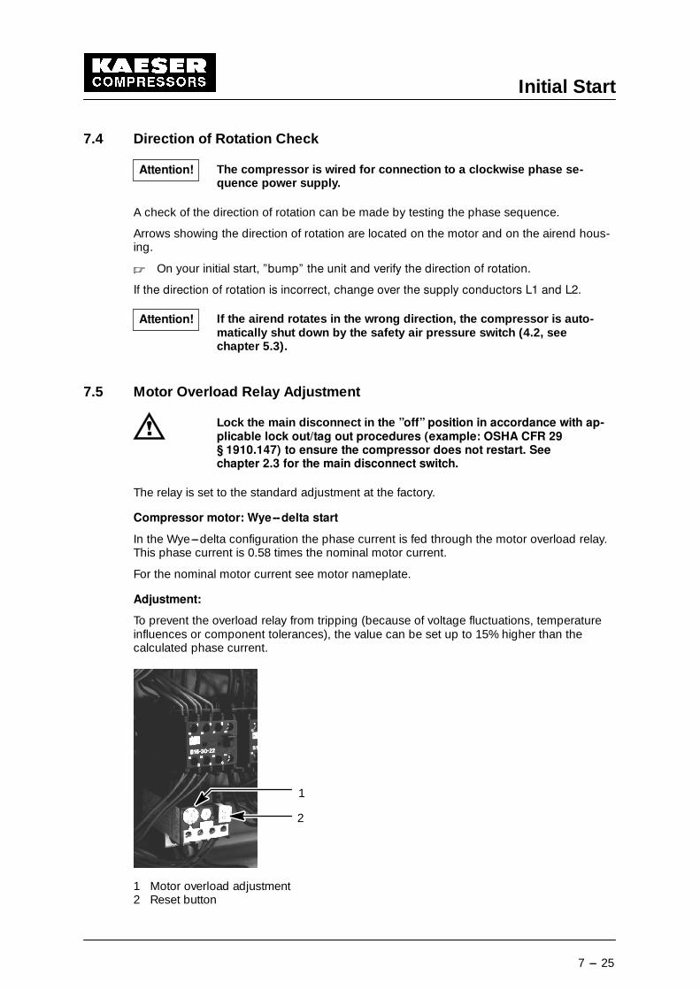
7.5 Motor Overload Relay Adjustment
Lock the main disconnect in the ”off” position in accordance with ap-plicable lock out/tag out procedures (example: OSHA CFR 29§ 1910.147) to ensure the compressor does not restart. Seechapter 2.3 for the main disconnect switch.
The relay is set to the standard adjustment at the factory.
Compressor motor: Wye--delta start
In the Wye---delta configuration the phase current is fed through the motor overload relay.This phase current is 0.58 times the nominal motor current.
For the nominal motor current see motor nameplate.
Adjustment:
To prevent the overload relay from tripping (because of voltage fluctuations, temperatureinfluences or component tolerances), the value can be set up to 15% higher than thecalculated phase current.
1
2
1 Motor overload adjustment2 Reset button
Attention!
Attention!
Initial Start
7 --- 26
7.6 Setting the Air System PressureThe air system pressure is preset at the factory. It can be changed in SIGMA CONTROL tomatch customer’s operational requirements if the password is known. For further details,consult the SIGMA CONTROL service manual.
Switching from full load to idle running may take place no more fre-quently than 2 times per minute.
Switching frequency can be improved by increasing the difference between cut---in andcut---out pressure.
In addition, a larger air receiver can be installed to increase buffer capacity.
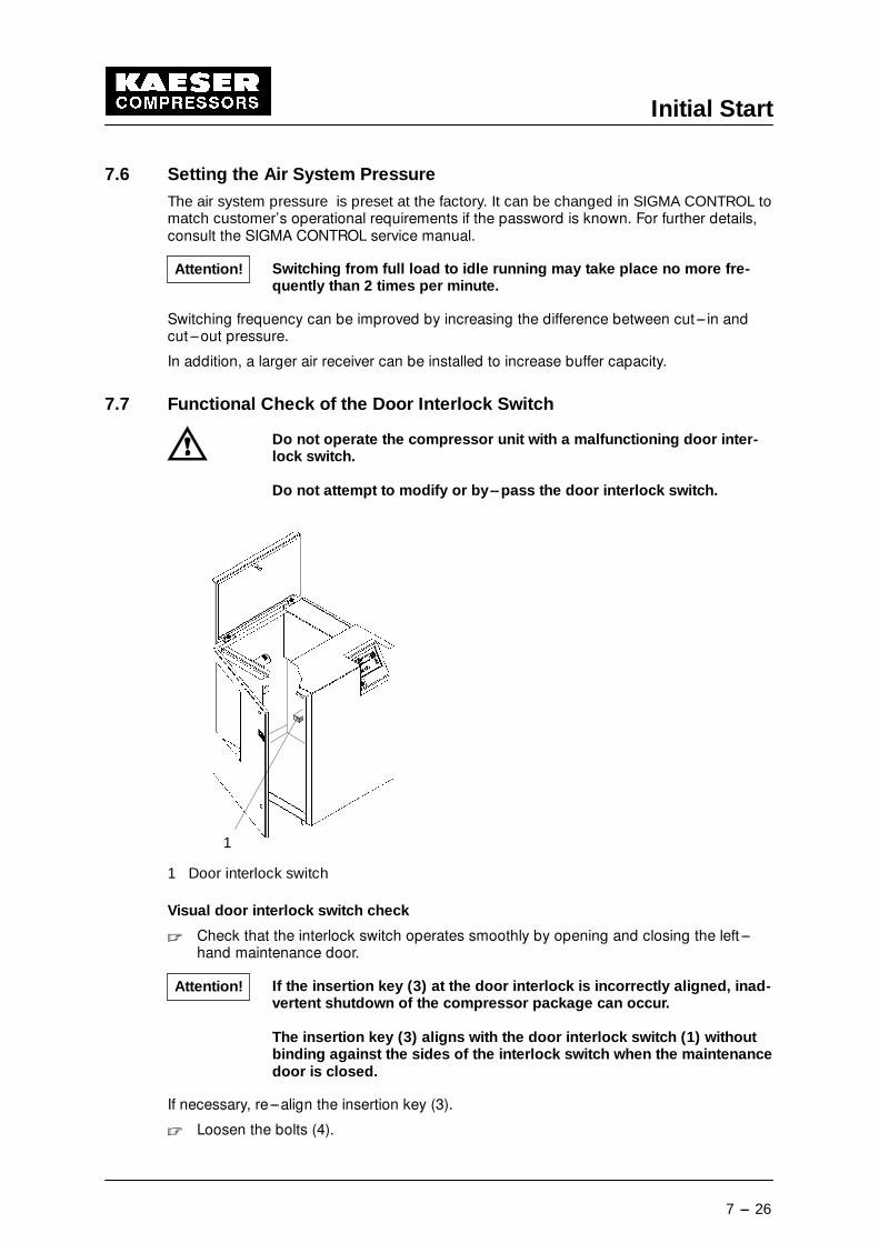
7.7 Functional Check of the Door Interlock Switch
Do not operate the compressor unit with a malfunctioning door inter-lock switch.
Do not attempt to modify or by--pass the door interlock switch.
1
1 Door interlock switch
Visual door interlock switch check
� Check that the interlock switch operates smoothly by opening and closing the left ---hand maintenance door.
If the insertion key (3) at the door interlock is incorrectly aligned, inad-vertent shutdown of the compressor package can occur.
The insertion key (3) aligns with the door interlock switch (1) withoutbinding against the sides of the interlock switch when the maintenancedoor is closed.
If necessary, re---align the insertion key (3).
� Loosen the bolts (4).
Attention!
Attention!
Initial Start
7 --- 27
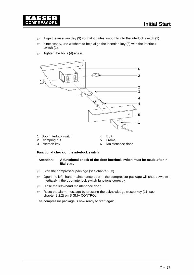
� Align the insertion dey (3) so that it glides smoothly into the interlock switch (1).
� If necessary, use washers to help align the insertion key (3) with the interlockswitch (1).
� Tighten the bolts (4) again.
1
4
4
32
2
6
5
1 Door interlock switch 4 Bolt2 Clamping nut 5 Frame3 Insertion key 6 Maintenance door
Functional check of the interlock switch
A functional check of the door interlock switch must be made after in-itial start.
� Start the compressor package (see chapter 8.3).
� Open the left ---hand maintenance door --- the compressor package will shut down im-mediately if the door interlock switch functions correctly.
� Close the left ---hand maintenance door.
� Reset the alarm message by pressing the acknowledge (reset) key (11, seechapter 8.2.2) on SIGMA CONTROL.
The compressor package is now ready to start again.
Attention!
Initial Start
7 --- 28
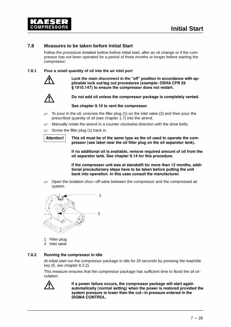
7.8 Measures to be taken before Initial StartFollow the procedure detailed bellow before initial start, after an oil change or if the com-pressor has not been operated for a period of three months or longer before starting thecompressor:
7.8.1 Pour a small quantity of oil into the air inlet port
Lock the main disconnect in the ”off” position in accordance with ap-plicable lock out/tag out procedures (example: OSHA CFR 29§ 1910.147) to ensure the compressor does not restart.
Do not add oil unless the compressor package is completely vented.
See chapter 9.10 to vent the compressor.
� To pour in the oil, unscrew the filler plug (1) on the inlet valve (2) and then pour theprescribed quantity of oil (see chapter 1.7) into the airend.
� Manually rotate the airend in a counter clockwise direction with the drive belts.
� Screw the filler plug (1) back in.
This oil must be of the same type as the oil used to operate the com-pressor (see label near the oil filler plug on the oil separator tank).
If no additional oil is available, remove required amount of oil from theoil separator tank. See chapter 9.14 for this procedure.
If the compressor unit was at standstill for more than 12 months, addi-tional precautionary steps have to be taken before putting the unitback into operation. In this case consult the manufacturer.
� Open the isolation shut---off valve between the compressor and the compressed airsystem.
2
1
1 Filler plug2 Inlet valve
7.8.2 Running the compressor in idle
At initial start run the compressor package in idle for 20 seconds by pressing the load/idlekey (5, see chapter 8.2.2).
This measure ensures that the compressor package has sufficient time to flood the oil cir-culation.
If a power failure occurs, the compressor package will start againautomatically (normal setting) when the power is restored provided thesystem pressure is lower than the cut-- in pressure entered in theSIGMA CONTROL.
Attention!
Operation
8 --- 29
8 Operation
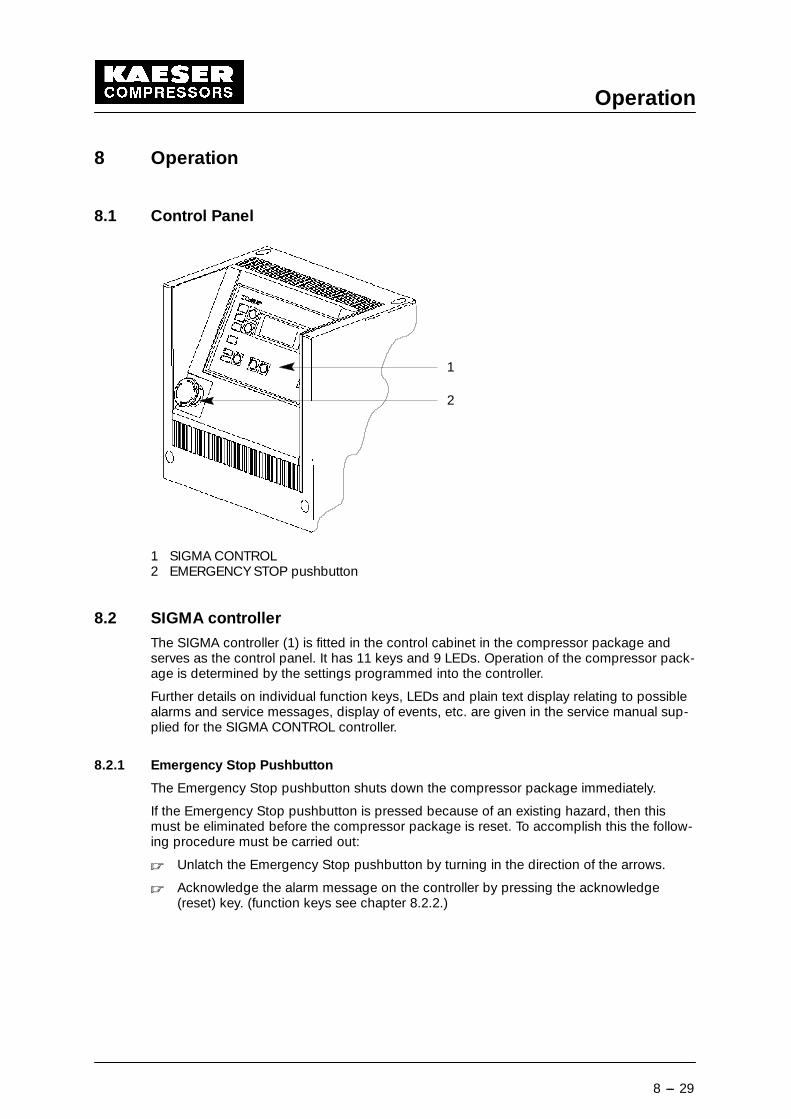
8.1 Control Panel
1
2
1 SIGMA CONTROL2 EMERGENCY STOP pushbutton
8.2 SIGMA controller
The SIGMA controller (1) is fitted in the control cabinet in the compressor package andserves as the control panel. It has 11 keys and 9 LEDs. Operation of the compressor pack-age is determined by the settings programmed into the controller.
Further details on individual function keys, LEDs and plain text display relating to possiblealarms and service messages, display of events, etc. are given in the service manual sup-plied for the SIGMA CONTROL controller.
8.2.1 Emergency Stop Pushbutton
The Emergency Stop pushbutton shuts down the compressor package immediately.
If the Emergency Stop pushbutton is pressed because of an existing hazard, then thismust be eliminated before the compressor package is reset. To accomplish this the follow-ing procedure must be carried out:
� Unlatch the Emergency Stop pushbutton by turning in the direction of the arrows.
� Acknowledge the alarm message on the controller by pressing the acknowledge(reset) key. (function keys see chapter 8.2.2.)
Operation
8 --- 30
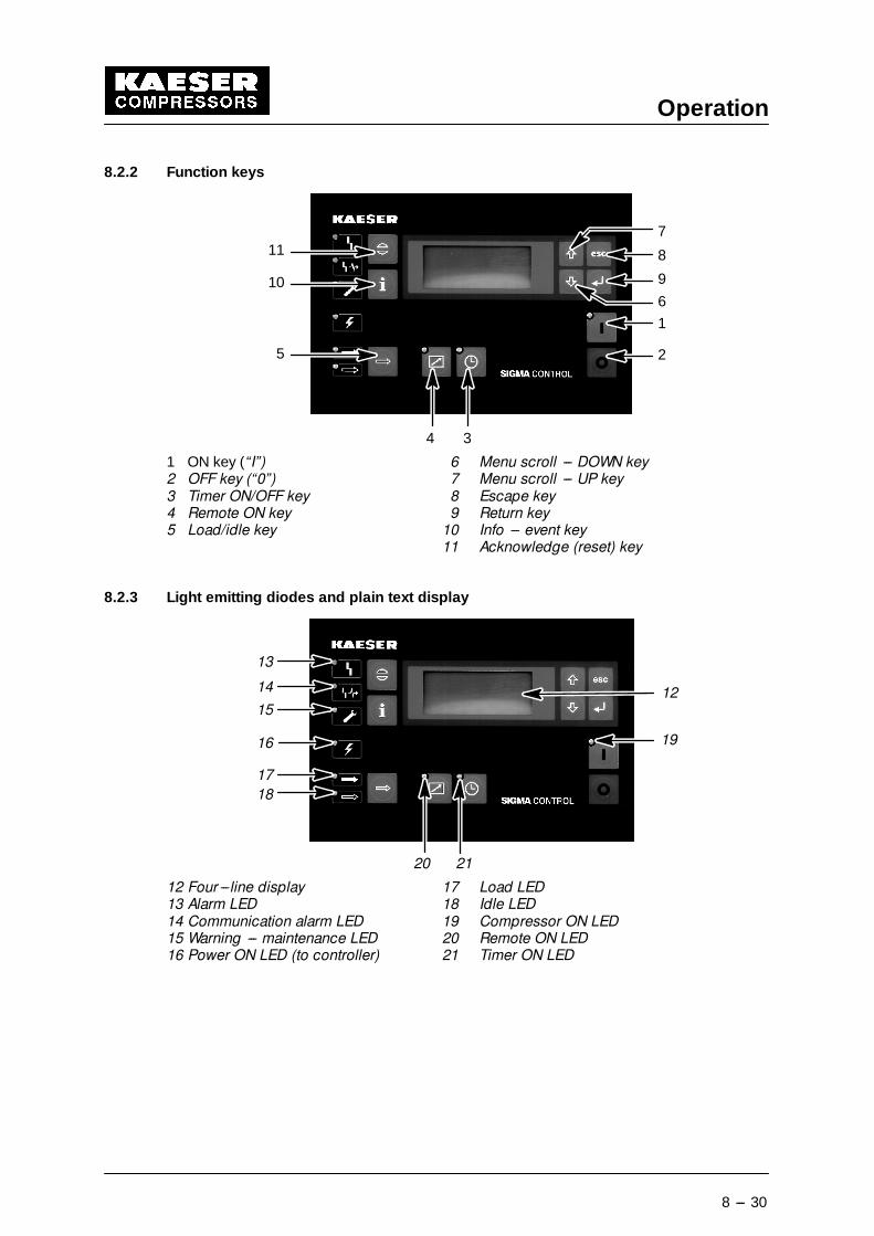
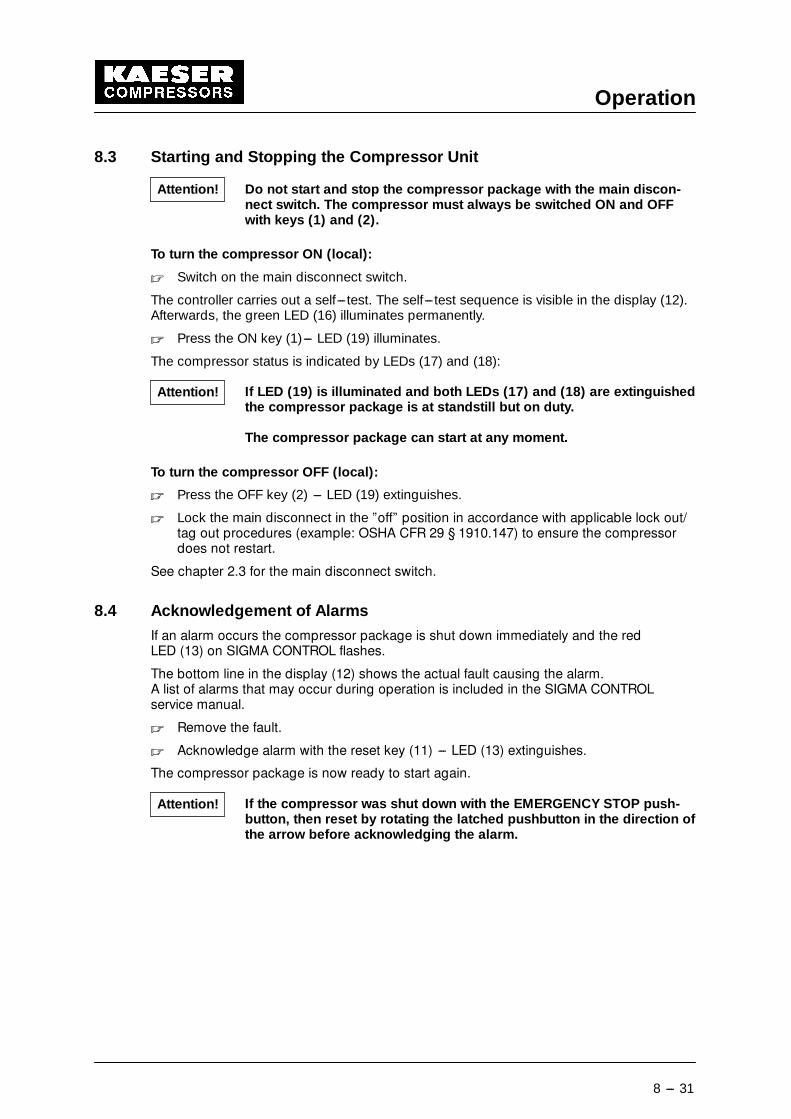
8.2.2 Function keys
1
2
8
9
4 3
11
10
5
7
6
1 ON key (“I”) 6 Menu scroll --- DOWN key2 OFF key (“0”) 7 Menu scroll --- UP key3 Timer ON/OFF key 8 Escape key4 Remote ON key 9 Return key5 Load/idle key 10 Info --- event key
11 Acknowledge (reset) key
8.2.3 Light emitting diodes and plain text display
12
13
19
14
15
16
17
18
20 21
12 Four ---line display 17 Load LED13 Alarm LED 18 Idle LED14 Communication alarm LED 19 Compressor ON LED15 Warning --- maintenance LED 20 Remote ON LED16 Power ON LED (to controller) 21 Timer ON LED
Operation
8 --- 31
8.3 Starting and Stopping the Compressor Unit
Do not start and stop the compressor package with the main discon-nect switch. The compressor must always be switched ON and OFFwith keys (1) and (2).
To turn the compressor ON (local):
� Switch on the main disconnect switch.
The controller carries out a self---test. The self---test sequence is visible in the display (12).Afterwards, the green LED (16) illuminates permanently.
� Press the ON key (1)--- LED (19) illuminates.
The compressor status is indicated by LEDs (17) and (18):
If LED (19) is illuminated and both LEDs (17) and (18) are extinguishedthe compressor package is at standstill but on duty.
The compressor package can start at any moment.
To turn the compressor OFF (local):
� Press the OFF key (2) --- LED (19) extinguishes.
� Lock the main disconnect in the ”off” position in accordance with applicable lock out/tag out procedures (example: OSHA CFR 29 § 1910.147) to ensure the compressordoes not restart.
See chapter 2.3 for the main disconnect switch.
8.4 Acknowledgement of Alarms
If an alarm occurs the compressor package is shut down immediately and the redLED (13) on SIGMA CONTROL flashes.
The bottom line in the display (12) shows the actual fault causing the alarm.A list of alarms that may occur during operation is included in the SIGMA CONTROLservice manual.
� Remove the fault.
� Acknowledge alarm with the reset key (11) --- LED (13) extinguishes.
The compressor package is now ready to start again.
If the compressor was shut down with the EMERGENCY STOP push-button, then reset by rotating the latched pushbutton in the direction ofthe arrow before acknowledging the alarm.
Attention!
Attention!
Attention!
Operation
8 --- 32
8.5 Acknowledgement of Service Messages
When maintenance is due the yellow LED (15) on SIGMA CONTROL flashes.
Maintenance due is shown in the display (12).A list of service messages that may occur during operation is included in theSIGMA CONTROL service manual.
� Carry out the maintenance work.
� Acknowledge service message with the reset key (11) --- LED (15) extinguishes.
When the respective maintenance has been carried out, the remaininginterval period (programmed interval until the next maintenance is due)must be reset.
Detailed information on resetting service counters is to be found in the service manual forSIGMA CONTROL.
Attention!
Operation
8 --- 33
8.6 Trouble shooting: Possible cause---Remedy
The removal of faults that are not explicitly described in this servicemanual may only be carried out by KAESER or by an authorisedKAESER service agency.
8.6.1 Airend temperature is too high (greater than 167�F--200�F)
Possible cause: Remedy:
Cooling air inlet or outlet is too close towall or other blockage.
Situate unit for adequate air flow.
Air intake filter mats are clogged. Clean the mats or replace if necessary.
Ambient temperature is too high. Provide cooler air from other source ormove compressor to a cooler location.See chapter 1.6.
Ambient temperature too low. Provide warmer air from other sourceor move compressor to warmer loca-tion or add a cabinet heater. See chap-ter 1.6.
Cooling air supply is inadequate. Provide required amount of ventilation.
If cooling air outlet duct is used it maybe too narrow or too long.
Consult authorized KAESER distributorfor duct requirements.
On air cooled units the fins of the cool-ers (oil cooler and air aftercooler) areclogged.
Clean with compressed air, water orsteam injector. See chapter 9.13.
On water cooled units the heat ex-changer elements may be clogged.
Inspect heat exchanger elements.Clean or replace as necessary.
Oil level is low. Check oil level and add necessaryamount of recommended oil.
Check dirt trap strainer in oil return linefor possible contamination.
Thermostatic valve is not functioningcorrectly.
Check the valve spring and actuatingpiston. Replace defective parts.
Idle pressure is too low for proper oilcirculation.
Check idle pressure at the separatortank. If the pressure is low check theinlet valve. Adjust inlet valve to main-tain adequate idle pressure.
Wrong oil is used. Drain old oil completely and replacewith recommended type.
Consult authorized KAESER distributorfor other oil types not listed.
Oil filter is clogged. Replace filter.
Airend is defective. Check airend and replace if defective.
Operation
8 --- 34
8.6.2 Motor overload relay switches the unit off
Possible cause: Remedy:
Overload relay is defective or setting iswrong.
Check line current and adjust overloadrelay as necessary.
Replace relay if defective.
Motor is running two phase: defectivemotor or blown fuse.
Check input power, check wiring, tigh-ten any loose connections.
Replace fuse(s) or motor if necessary.
Oil separator cartridge is contamina-ted.
Check pressure differential across car-tridge. Replace cartridge and dirt trapstrainer if necessary.
Motor starts against pressure becausesystem does not get vented.
Check ball valve in vent line and openif it is closed.
Check the diaphragm in the vent valveand replace if defective.
Check the minimum pressure checkvalve. Adjust minimum pressure func-tion or replace defective parts as ne-cessary.
Airend is defective. Check airend and replace if defective.
Ambient temperature is above 104�F. Provide adequate compressor ventila-tion.
Defective motor: bad bearings or shortcircuit in windings.
Repair or replace motor.
8.6.3 Compressor is running but produces no pressure
Possible cause: Remedy:
Airend rotates in wrong direction. Reverse motor polarity.
Inlet valve does not open or opensonly partially.
Check the inlet valve, control valve andlines. Replace defective parts asneeded
Vent valve does not close at full load. Check the combined control/vent valveand control lines. Replace defectiveparts as needed.
Minimum pressure check valve is de-fective.
Check the valve and replace defectiveparts.
Leaks in plant system. Check for open valves, loose connec-tions, defective tools, etc.
Plant system air, demand exceeds ca-pacity of compressor
Reduce system demand or installadditional compressor(s).
Air leak in unit. Tighten loose connections, repair orreplace defective parts as necessary.
Socket is still in the hose coupling atthe oil separator tank or aftercooler.
Remove socket from coupling.
Operation
8 --- 35
Safety relief valve has blown off. See chapter 8.6.6.
Airend is defective. With unit running, slowly and carefullyplace hand over air inlet filter casing.There should be considerable suction.If not, airend is producing no pressure.
8.6.4 Oil leaks out of air filter
Possible cause: Remedy:
Oil level in separator tank is too high. Drain oil to correct level.
Inlet valve faulty. Find the fault and replace the defectivepart.
8.6.5 Full -- load/Idle sequence occurs too frequently (short cycles)
Possible cause: Remedy:
Receiver tank size is too small or thereis no tank.
Consult authorized KAESER distributorfor recommended tank size.
Diameter of hose connecting the unitto the receiver tank is too small.
Connecting hose diameter should notbe smaller than the air discharge pipediameter. Install larger hose if neces-sary.
Minimum pressure check valve leaks. Check the valve and replace defectiveparts.
Flow is restricted at discharge. Look for plugged filters, partiallyclosed valves, frozen pipes or malfunc-tioning pressure regulators.
8.6.6 Safety relief valve blows off
Possible cause: Remedy:
System does not discharge at idle. Make sure ball valve in vent line isopen. Check the control lines, inletvalve and combined control/vent valve.Replace defective parts as needed.
Oil separator cartridge is contamina-ted.
Check the cartridge pressure differen-tial and replace cartridge if necessary.
Minimum pressure check valve doesnot open.
Check the valve for blockage and re-place defective parts as necessary.
Safety relief valve not properly sizedfor the pressure of the compressorunit.
Check blow---off pressure and com-pare to name plate of the compressor.Replace if necessary.
8.6.7 Oil inside the unit
Possible cause: Remedy:
Socket is still in the hose coupling atthe separator tank.
Remove the socket from the coupling.
Safety valve has blown off. See chapter 8.6.6.
Oil is coming out of air filter. See chapter 8.6.4.
Hose coupling on separator tank isloose.
Tighten coupling or replace asneeded.
Oil cooler leaks. Replace oil cooler.
Operation
8 --- 36
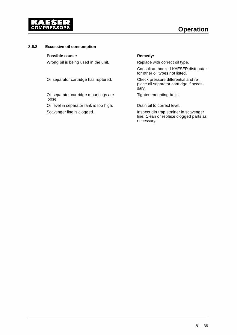
8.6.8 Excessive oil consumption
Possible cause: Remedy:
Wrong oil is being used in the unit. Replace with correct oil type.
Consult authorized KAESER distributorfor other oil types not listed.
Oil separator cartridge has ruptured. Check pressure differential and re-place oil separator cartridge if neces-sary.
Oil separator cartridge mountings areloose.
Tighten mounting bolts.
Oil level in separator tank is too high. Drain oil to correct level.
Scavenger line is clogged. Inspect dirt trap strainer in scavengerline. Clean or replace clogged parts asnecessary.
Maintenance
9 --- 37
9 Maintenance
9.1 Observe the following rules during all maintenance and servicing work:
Work on power driven equipment may only be carried out by trained orspecialized personnel. Follow all applicable OSHA and local safetyregulations.
If a power failure occurs, the compressor package starts again auto-matically (normal setting) provided the line pressure is lower than thepressure threshold parameter entered in SIGMA CONTROL.
Lock the main disconnect switch in the ”off” position in accordancewith applicable lock out/tag out procedures to ensure the compressordoes not restart (see chapter 2.3 for main disconnect switch).
Ensure that no maintenance personnel is working on the compressorunit, that all panels are latched back on again and all maintenancedoors are closed before restarting the compressor unit.
To start the compressor unit see chapter 8.3).
The venting nozzle required to vent the oil separator tank (for mainten-ance work such as topping up the oil, oil change and filter change) isfitted to the hose coupling (3, see chapter 9.10).
Carry out a visual and functional check of the door interlock switchafter any maintenance and servicing work.
See chapter 7.7 for details.
The following points must be observed when handling lubricating andcooling materials:
Avoid contact with skin and eyes.Do not inhale vapors and oil mist.Do not eat or drink when handling such materials.Fire, open flame and smoking are strictly forbidden.
Ensure that all lubricants, consumable materials and replacementparts accumulating during operation and servicing of the compressorpackage are disposed of according to environmental regulations.
Attention!
Maintenance
9 --- 38
9.2 Regular Maintenance
Interval* Work to be done See chapter
2 and 24 h after initialstart
Check the v---belt tension 9.4
50 h after initial start Check all electrical connections for tightnessand tighten if necessary
200 h after initial start Replace the oil filter 9.11
Weekly Check the oil level 9.12
Check the filter mats for contamination 9.6
500 h Check the v---belt tension 9.4
Clean or replace the air filter 9.7
1000 h Check the oil cooler and air aftercooler for con-tamination
9.13
Clean or replace the filter mats 9.6
up to 3000 h or atleast annually
Replace the oil filter 9.11
Proper interval varies.See chapter 1.8
Change the oil 9.14
up to 9000 h or at leastevery 3 years
Change the oil separator cartridge 9.15
Annually Check all electrical connections for tightnessand tighten if necessary
12000 h Have the valves inspected by an authorizedKAESER Service agent
Annually Have the safety relief valve checked byauthorized KAESER Service agent
9.9
6000/12000 hours or atleast within three years
Have the compressor motor bearings relubrica-ted by authorized KAESER distributors*
9.8
* The maintenance period can vary depending on the cycle rate and environmentalconditions.
We urgently recommend that a record is kept of the maintenance work done (see chap-ter 9.16).
Maintenance
9 --- 39
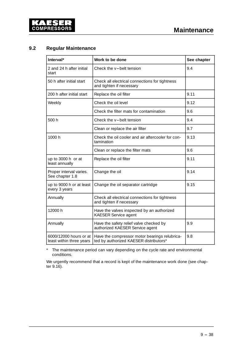
9.3 Opening and Closing the Compressor Package
To open:
� Open the maintenance door (1).
� Move the lever (A) in the direction of the arrow and lift up the maintenance door (2).
� Loosen the screws (B) and remove the panel (3).
To close:
� Close the panel (3) the maintenance door (2) and the maintenance door (1) in the re-verse order.
Close all maintenance doors and panels correctly before starting thecompressor package.
A B
3
1
2
B
1 Maintenance door2 Maintenance door3 Cover panel
Maintenance
9 --- 40
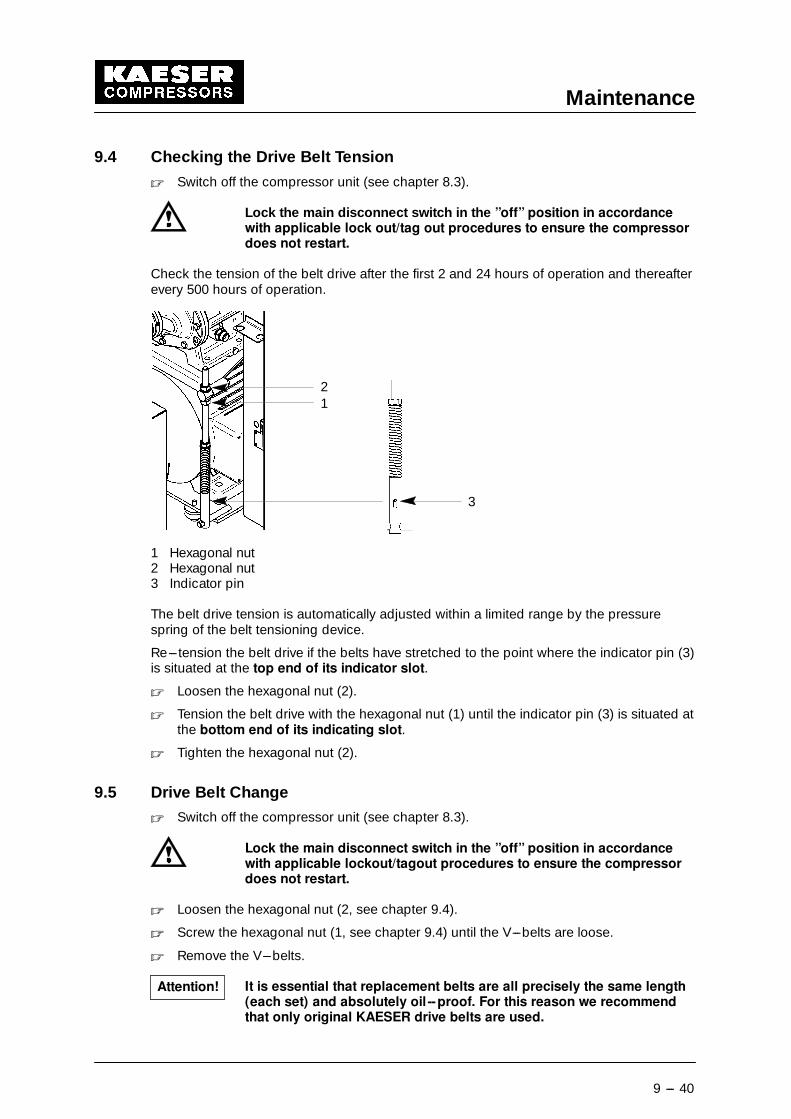
9.4 Checking the Drive Belt Tension
� Switch off the compressor unit (see chapter 8.3).
Lock the main disconnect switch in the ”off” position in accordancewith applicable lock out/tag out procedures to ensure the compressordoes not restart.
Check the tension of the belt drive after the first 2 and 24 hours of operation and thereafterevery 500 hours of operation.
21
3
1 Hexagonal nut2 Hexagonal nut3 Indicator pin
The belt drive tension is automatically adjusted within a limited range by the pressurespring of the belt tensioning device.
Re---tension the belt drive if the belts have stretched to the point where the indicator pin (3)is situated at the top end of its indicator slot.
� Loosen the hexagonal nut (2).
� Tension the belt drive with the hexagonal nut (1) until the indicator pin (3) is situated atthe bottom end of its indicating slot.
� Tighten the hexagonal nut (2).
9.5 Drive Belt Change
� Switch off the compressor unit (see chapter 8.3).
Lock the main disconnect switch in the ”off” position in accordancewith applicable lockout/tagout procedures to ensure the compressordoes not restart.
� Loosen the hexagonal nut (2, see chapter 9.4).
� Screw the hexagonal nut (1, see chapter 9.4) until the V---belts are loose.
� Remove the V---belts.
It is essential that replacement belts are all precisely the same length(each set) and absolutely oil --proof. For this reason we recommendthat only original KAESER drive belts are used.
Attention!
Maintenance
9 --- 41
� Place the new V---belts over the motor and compressor pulleys without straining them.
� Set the belt drive tension (see chapter 9.4).
Check the belt drive tension after 2 hours of operation and then againafter 24 hours of operation, as experience shows that the belts stretchmostly during this period.
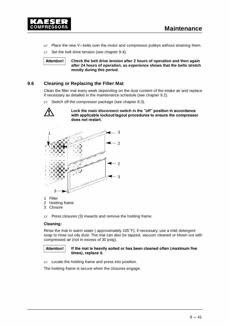
9.6 Cleaning or Replacing the Filter Mat
Clean the filter mat every week depending on the dust content of the intake air and replaceif necessary as detailed in the maintenance schedule (see chapter 9.2).
� Switch off the compressor package (see chapter 8.3).
Lock the main disconnect switch in the ”off” position in accordancewith applicable lockout/tagout procedures to ensure the compressordoes not restart.
1 3
2
2
3
3
3
1 Filter2 Holding frame3 Closure
� Press closures (3) inwards and remove the holding frame.
Cleaning:
Rinse the mat in warm water ( approximately 105�F), if necessary, use a mild detergentsoap to rinse out oily dust. The mat can also be tapped, vacuum cleaned or blown out withcompressed air (not in excess of 30 psig).
If the mat is heavily soiled or has been cleaned often (maximum fivetimes), replace it.
� Locate the holding frame and press into position.
The holding frame is secure when the closures engage.
Attention!
Attention!
Maintenance
9 --- 42
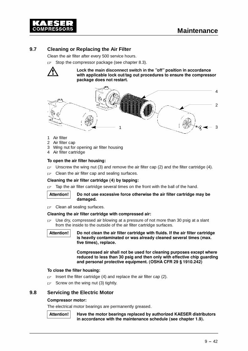
9.7 Cleaning or Replacing the Air FilterClean the air filter after every 500 service hours.
� Stop the compressor package (see chapter 8.3).
Lock the main disconnect switch in the ”off” position in accordancewith applicable lock out/tag out procedures to ensure the compressorpackage does not restart.
1
2
3
4
1 Air filter2 Air filter cap3 Wing nut for opening air filter housing4 Air filter cartridge
To open the air filter housing:
� Unscrew the wing nut (3) and remove the air filter cap (2) and the filter cartridge (4).
� Clean the air filter cap and sealing surfaces.
Cleaning the air filter cartridge (4) by tapping:
� Tap the air filter cartridge several times on the front with the ball of the hand.
Do not use excessive force otherwise the air filter cartridge may bedamaged.
� Clean all sealing surfaces.
Cleaning the air filter cartridge with compressed air:
� Use dry, compressed air blowing at a pressure of not more than 30 psig at a slantfrom the inside to the outside of the air filter cartridge surfaces.
Do not clean the air filter cartridge with fluids. If the air filter cartridgeis heavily contaminated or was already cleaned several times (max.five times), replace.
Compressed air shall not be used for cleaning purposes except wherereduced to less than 30 psig and then only with effective chip guardingand personal protective equipment. (OSHA CFR 29 § 1910.242)
To close the filter housing:
� Insert the filter cartridge (4) and replace the air filter cap (2).
� Screw on the wing nut (3) tightly.
9.8 Servicing the Electric MotorCompressor motor:
The electrical motor bearings are permanently greased.
Have the motor bearings replaced by authorized KAESER distributorsin accordance with the maintenance schedule (see chapter 1.9).
Attention!
Attention!
Attention!
Maintenance
9 --- 43
9.9 Testing the Safety Relief Valve on the Oil Separator TankTo test the set point of the safety relief valve, the compressor must be run so that its dis-charge pressure exceeds the maximum pressure set on the SIGMA CONTROL.
See chapter 1.5 for the safety relief valve activating pressure.
Have the safety relief valve tested by an authorized KAESER distribu-tor in accordance with the maintenance schedule (see chapter 9.2).
For more details see SIGMA CONTROL manual.
9.10 Venting the compressor unit� Switch off the compressor unit (see chapter 8.3).
Lock the main disconnect in the ”off” position in accordance with ap-plicable lock out/tag out procedures to ensure the compressor doesnot restart.
Lock the isolation shut--off valve in the ”closed” position and vent allcompressed air trapped between the compressor and the isolationshut--off valve in accordance with applicable lock out/ tag out pro-cedures.
The oil circulation system of the compressor package vents automatically.
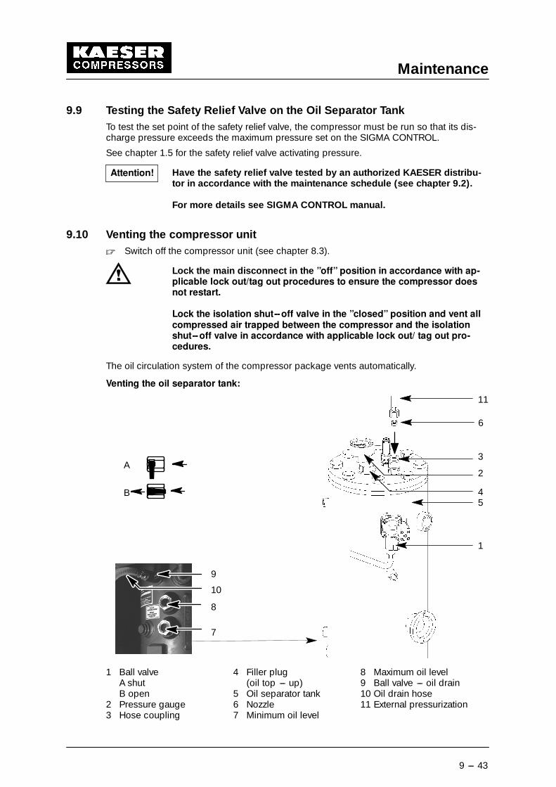
Venting the oil separator tank:
8
7
9
10
B
A
11
3
1
2
45
6
1 Ball valve 4 Filler plug 8 Maximum oil levelA shut (oil top --- up) 9 Ball valve --- oil drainB open 5 Oil separator tank 10 Oil drain hose
2 Pressure gauge 6 Nozzle 11 External pressurization3 Hose coupling 7 Minimum oil level
Attention!
Maintenance
9 --- 44
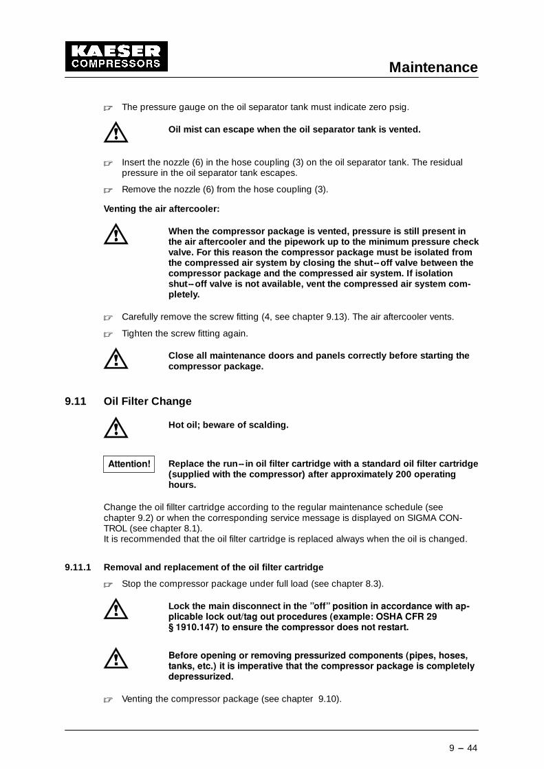
� The pressure gauge on the oil separator tank must indicate zero psig.
Oil mist can escape when the oil separator tank is vented.
� Insert the nozzle (6) in the hose coupling (3) on the oil separator tank. The residualpressure in the oil separator tank escapes.
� Remove the nozzle (6) from the hose coupling (3).
Venting the air aftercooler:
When the compressor package is vented, pressure is still present inthe air aftercooler and the pipework up to the minimum pressure checkvalve. For this reason the compressor package must be isolated fromthe compressed air system by closing the shut--off valve between thecompressor package and the compressed air system. If isolationshut--off valve is not available, vent the compressed air system com-pletely.
� Carefully remove the screw fitting (4, see chapter 9.13). The air aftercooler vents.
� Tighten the screw fitting again.
Close all maintenance doors and panels correctly before starting thecompressor package.
9.11 Oil Filter Change
Hot oil; beware of scalding.
Replace the run-- in oil filter cartridge with a standard oil filter cartridge(supplied with the compressor) after approximately 200 operatinghours.
Change the oil fillter cartridge according to the regular maintenance schedule (seechapter 9.2) or when the corresponding service message is displayed on SIGMA CON-TROL (see chapter 8.1).It is recommended that the oil filter cartridge is replaced always when the oil is changed.
9.11.1 Removal and replacement of the oil filter cartridge
� Stop the compressor package under full load (see chapter 8.3).
Lock the main disconnect in the ”off” position in accordance with ap-plicable lock out/tag out procedures (example: OSHA CFR 29§ 1910.147) to ensure the compressor does not restart.
Before opening or removing pressurized components (pipes, hoses,tanks, etc.) it is imperative that the compressor package is completelydepressurized.
� Venting the compressor package (see chapter 9.10).
Attention!
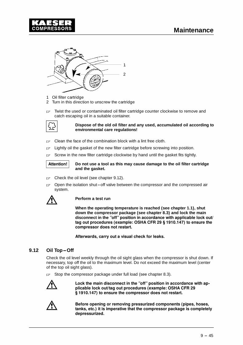
Maintenance
9 --- 45
2
1
1 Oil filter cartridge2 Turn in this direction to unscrew the cartridge
� Twist the used or contaminated oil filter cartridge counter clockwise to remove andcatch escaping oil in a suitable container.
Dispose of the old oil filter and any used, accumulated oil according toenvironmental care regulations!
� Clean the face of the combination block with a lint free cloth.
� Lightly oil the gasket of the new filter cartridge before screwing into position.
� Screw in the new filter cartridge clockwise by hand until the gasket fits tightly.
Do not use a tool as this may cause damage to the oil filter cartridgeand the gasket.
� Check the oil level (see chapter 9.12).
� Open the isolation shut---off valve between the compressor and the compressed airsystem.
Perform a test run
When the operating temperature is reached (see chapter 1.1), shutdown the compressor package (see chapter 8.3) and lock the maindisconnect in the ”off” position in accordance with applicable lock out/tag out procedures (example: OSHA CFR 29 § 1910.147) to ensure thecompressor does not restart.
Afterwards, carry out a visual check for leaks.
9.12 Oil Top---OffCheck the oil level weekly through the oil sight glass when the compressor is shut down. Ifnecessary, top off the oil to the maximum level. Do not exceed the maximum level (centerof the top oil sight glass).
� Stop the compressor package under full load (see chapter 8.3).
Lock the main disconnect in the ”off” position in accordance with ap-plicable lock out/tag out procedures (example: OSHA CFR 29§ 1910.147) to ensure the compressor does not restart.
Before opening or removing pressurized components (pipes, hoses,tanks, etc.) it is imperative that the compressor package is completelydepressurized.
Attention!
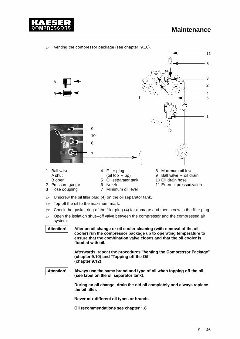
Maintenance
9 --- 46
� Venting the compressor package (see chapter 9.10).
8
7
9
10
B
A
11
3
1
2
45
6
1 Ball valve 4 Filler plug 8 Maximum oil levelA shut (oil top --- up) 9 Ball valve --- oil drainB open 5 Oil separator tank 10 Oil drain hose
2 Pressure gauge 6 Nozzle 11 External pressurization3 Hose coupling 7 Minimum oil level
� Unscrew the oil filler plug (4) on the oil separator tank.
� Top off the oil to the maximum mark.
� Check the gasket ring of the filler plug (4) for damage and then screw in the filler plug.
� Open the isolation shut---off valve between the compressor and the compressed airsystem.
After an oil change or oil cooler cleaning (with removal of the oilcooler) run the compressor package up to operating temperature toensure that the combination valve closes and that the oil cooler isflooded with oil.
Afterwards, repeat the procedures ‘‘Venting the Compressor Package’’(chapter 9.10) and “Topping off the Oil”(chapter 9.12).
Always use the same brand and type of oil when topping off the oil.(see label on the oil separator tank).
During an oil change, drain the old oil completely and always replacethe oil filter.
Never mix different oil types or brands.
Oil recommendations see chapter 1.8
Attention!
Attention!
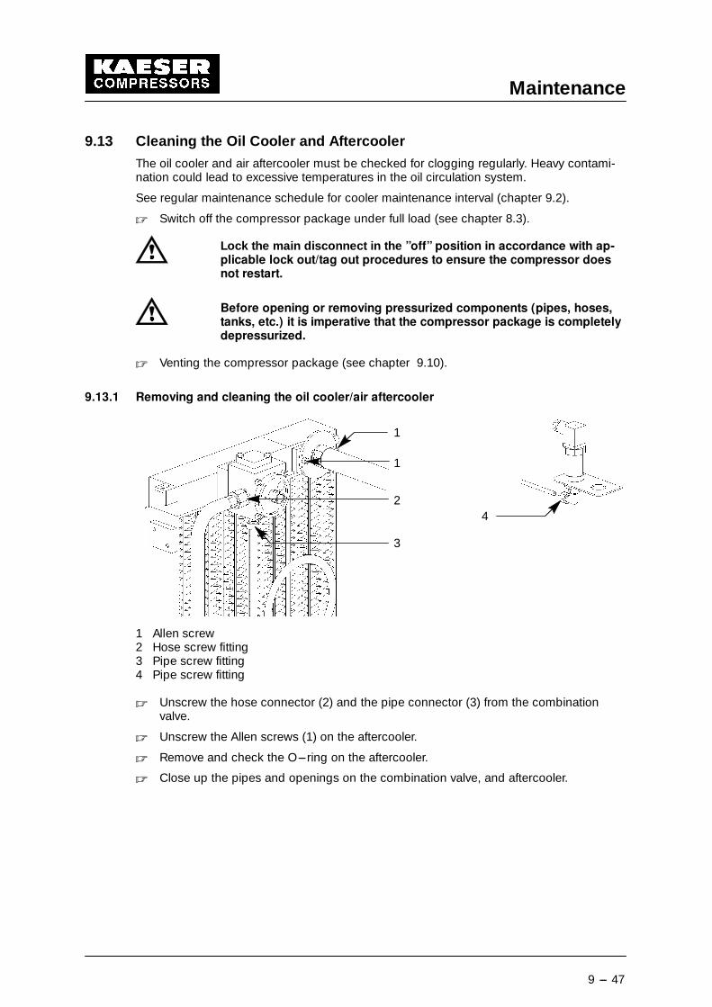
Maintenance
9 --- 47
9.13 Cleaning the Oil Cooler and Aftercooler
The oil cooler and air aftercooler must be checked for clogging regularly. Heavy contami-nation could lead to excessive temperatures in the oil circulation system.
See regular maintenance schedule for cooler maintenance interval (chapter 9.2).
� Switch off the compressor package under full load (see chapter 8.3).
Lock the main disconnect in the ”off” position in accordance with ap-plicable lock out/tag out procedures to ensure the compressor doesnot restart.
Before opening or removing pressurized components (pipes, hoses,tanks, etc.) it is imperative that the compressor package is completelydepressurized.
� Venting the compressor package (see chapter 9.10).
9.13.1 Removing and cleaning the oil cooler/air aftercooler
1
1
2
3
4
1 Allen screw2 Hose screw fitting3 Pipe screw fitting4 Pipe screw fitting
� Unscrew the hose connector (2) and the pipe connector (3) from the combinationvalve.
� Unscrew the Allen screws (1) on the aftercooler.
� Remove and check the O---ring on the aftercooler.
� Close up the pipes and openings on the combination valve, and aftercooler.
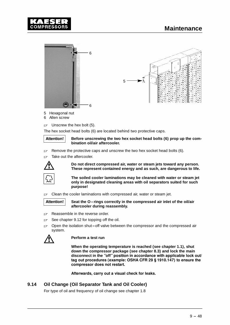
Maintenance
9 --- 48
5
6
6
5 Hexagonal nut6 Allen screw
� Unscrew the hex bolt (5).
The hex socket head bolts (6) are located behind two protective caps.
Before unscrewing the two hex socket head bolts (6) prop up the com-bination oil/air aftercooler.
� Remove the protective caps and unscrew the two hex socket head bolts (6).
� Take out the aftercooler.
Do not direct compressed air, water or steam jets toward any person.These represent contained energy and as such, are dangerous to life.
The soiled cooler laminations may be cleaned with water or steam jetonly in designated cleaning areas with oil separators suited for suchpurpose!
� Clean the cooler laminations with compressed air, water or steam jet.
Seat the O--rings correctly in the compressed air inlet of the oil/airaftercooler during reassembly.
� Reassemble in the reverse order.
� See chapter 9.12 for topping off the oil.
� Open the isolation shut---off valve between the compressor and the compressed airsystem.
Perform a test run
When the operating temperature is reached (see chapter 1.1), shutdown the compressor package (see chapter 8.3) and lock the maindisconnect in the ”off” position in accordance with applicable lock out/tag out procedures (example: OSHA CFR 29 § 1910.147) to ensure thecompressor does not restart.
Afterwards, carry out a visual check for leaks.
9.14 Oil Change (Oil Separator Tank and Oil Cooler)For type of oil and frequency of oil change see chapter 1.8
Attention!
Attention!
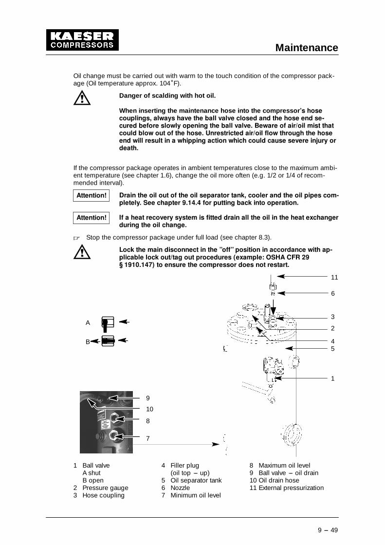
Maintenance
9 --- 49
Oil change must be carried out with warm to the touch condition of the compressor pack-age (Oil temperature approx. 104�F).
Danger of scalding with hot oil.
When inserting the maintenance hose into the compressor’s hosecouplings, always have the ball valve closed and the hose end se-cured before slowly opening the ball valve. Beware of air/oil mist thatcould blow out of the hose. Unrestricted air/oil flow through the hoseend will result in a whipping action which could cause severe injury ordeath.
If the compressor package operates in ambient temperatures close to the maximum ambi-ent temperature (see chapter 1.6), change the oil more often (e.g. 1/2 or 1/4 of recom-mended interval).
Drain the oil out of the oil separator tank, cooler and the oil pipes com-pletely. See chapter 9.14.4 for putting back into operation.
If a heat recovery system is fitted drain all the oil in the heat exchangerduring the oil change.
� Stop the compressor package under full load (see chapter 8.3).
Lock the main disconnect in the ”off” position in accordance with ap-plicable lock out/tag out procedures (example: OSHA CFR 29§ 1910.147) to ensure the compressor does not restart.
8
7
9
10
B
A
11
3
1
2
45
6
1 Ball valve 4 Filler plug 8 Maximum oil levelA shut (oil top --- up) 9 Ball valve --- oil drainB open 5 Oil separator tank 10 Oil drain hose
2 Pressure gauge 6 Nozzle 11 External pressurization3 Hose coupling 7 Minimum oil level
Attention!
Attention!
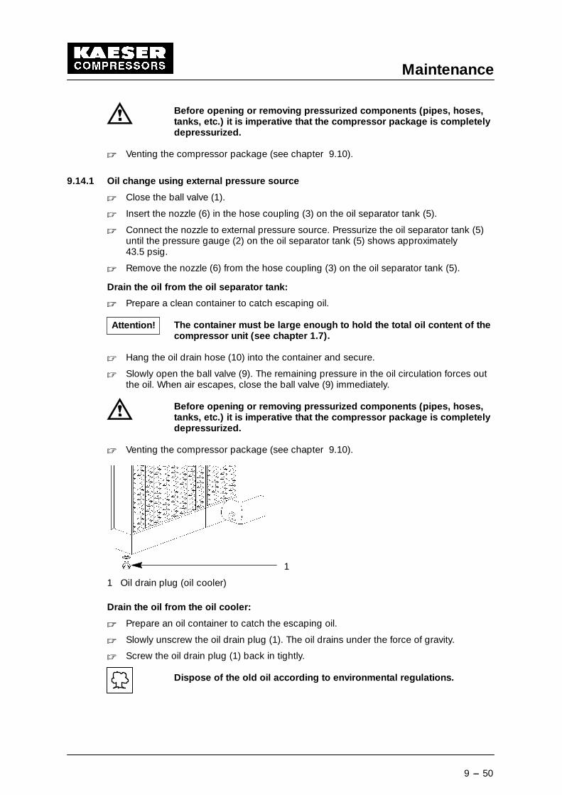
Maintenance
9 --- 50
Before opening or removing pressurized components (pipes, hoses,tanks, etc.) it is imperative that the compressor package is completelydepressurized.
� Venting the compressor package (see chapter 9.10).
9.14.1 Oil change using external pressure source
� Close the ball valve (1).
� Insert the nozzle (6) in the hose coupling (3) on the oil separator tank (5).
� Connect the nozzle to external pressure source. Pressurize the oil separator tank (5)until the pressure gauge (2) on the oil separator tank (5) shows approximately43.5 psig.
� Remove the nozzle (6) from the hose coupling (3) on the oil separator tank (5).
Drain the oil from the oil separator tank:
� Prepare a clean container to catch escaping oil.
The container must be large enough to hold the total oil content of thecompressor unit (see chapter 1.7).
� Hang the oil drain hose (10) into the container and secure.
� Slowly open the ball valve (9). The remaining pressure in the oil circulation forces outthe oil. When air escapes, close the ball valve (9) immediately.
Before opening or removing pressurized components (pipes, hoses,tanks, etc.) it is imperative that the compressor package is completelydepressurized.
� Venting the compressor package (see chapter 9.10).
1
1 Oil drain plug (oil cooler)
Drain the oil from the oil cooler:
� Prepare an oil container to catch the escaping oil.
� Slowly unscrew the oil drain plug (1). The oil drains under the force of gravity.
� Screw the oil drain plug (1) back in tightly.
Dispose of the old oil according to environmental regulations.
Attention!
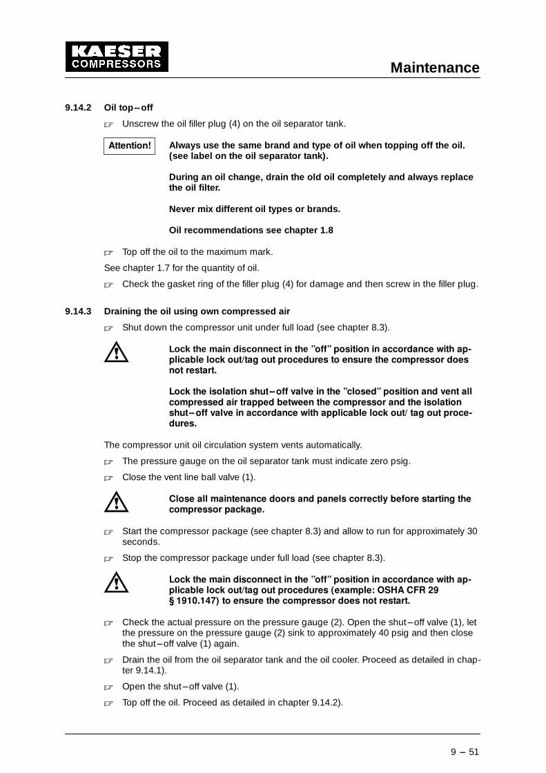
Maintenance
9 --- 51
9.14.2 Oil top--off
� Unscrew the oil filler plug (4) on the oil separator tank.
Always use the same brand and type of oil when topping off the oil.(see label on the oil separator tank).
During an oil change, drain the old oil completely and always replacethe oil filter.
Never mix different oil types or brands.
Oil recommendations see chapter 1.8
� Top off the oil to the maximum mark.
See chapter 1.7 for the quantity of oil.
� Check the gasket ring of the filler plug (4) for damage and then screw in the filler plug.
9.14.3 Draining the oil using own compressed air
� Shut down the compressor unit under full load (see chapter 8.3).
Lock the main disconnect in the ”off” position in accordance with ap-plicable lock out/tag out procedures to ensure the compressor doesnot restart.
Lock the isolation shut--off valve in the ”closed” position and vent allcompressed air trapped between the compressor and the isolationshut--off valve in accordance with applicable lock out/ tag out proce-dures.
The compressor unit oil circulation system vents automatically.
� The pressure gauge on the oil separator tank must indicate zero psig.
� Close the vent line ball valve (1).
Close all maintenance doors and panels correctly before starting thecompressor package.
� Start the compressor package (see chapter 8.3) and allow to run for approximately 30seconds.
� Stop the compressor package under full load (see chapter 8.3).
Lock the main disconnect in the ”off” position in accordance with ap-plicable lock out/tag out procedures (example: OSHA CFR 29§ 1910.147) to ensure the compressor does not restart.
� Check the actual pressure on the pressure gauge (2). Open the shut---off valve (1), letthe pressure on the pressure gauge (2) sink to approximately 40 psig and then closethe shut---off valve (1) again.
� Drain the oil from the oil separator tank and the oil cooler. Proceed as detailed in chap-ter 9.14.1).
� Open the shut---off valve (1).
� Top off the oil. Proceed as detailed in chapter 9.14.2).
Attention!
Maintenance
9 --- 52
9.14.4 Procedure for putting back into operation
� Refer to chapter 7.8.1 and follow the instructions in section ‘‘Pouring a small quantityof oil into the air inlet port” .
� Refer to chapter 7.8.2 and followthe instructions in section ”Running the compressorpackage in idle”.
� Refer to chapter 9.10 and follow the instructions in section ‘‘Venting the compressorpackage”.
� Top off with oil again (see chapter 9.14.2).
� Open the shut---off valve between the compressor package and the air system.
� Start the compressor package (see chapter 8.3) and run until working temperature isreached (see chapter 1.1).
� Top off the oil, see chapter 9.12.
Perform a test run
When the operating temperature is reached (see chapter 1.1), shutdown the compressor package (see chapter 8.3) and lock the maindisconnect in the ”off” position in accordance with applicable lock out/tag out procedures (example: OSHA CFR 29 § 1910.147) to ensure thecompressor does not restart.
Afterwards, carry out a visual check for leaks.
9.15 Changing the Oil Separator Cartridge
The service life of the oil separator cartridge is strongly influenced by the degree of conta-mination of inlet air and on strict adherence to the recommended maintenance intervals ofthe air and oil filters.
We recommend that the oil separator cartridge is changed with the oil or when the relevantservice message / alarm message is displayed on SIGMA CONTROL (see chapter 8.1).
� Stop the compressor package under full load (see chapter 8.3).
Lock the main disconnect in the ”off” position in accordance with ap-plicable lock out/tag out procedures (example: OSHA CFR 29§ 1910.147) to ensure the compressor does not restart.
Before opening or removing pressurized components (pipes, hoses,tanks, etc.) it is imperative that the compressor package is completelydepressurized.
� Venting the compressor package (see chapter 9.10).
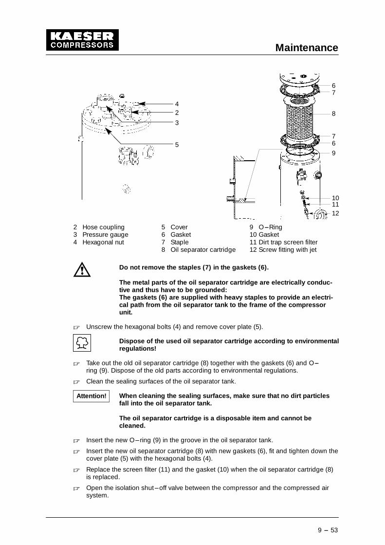
Maintenance
9 --- 53
67
8
76
9
101112
5
42
3
2 Hose coupling 5 Cover 9 O---Ring3 Pressure gauge 6 Gasket 10 Gasket4 Hexagonal nut 7 Staple 11 Dirt trap screen filter
8 Oil separator cartridge 12 Screw fitting with jet
Do not remove the staples (7) in the gaskets (6).
The metal parts of the oil separator cartridge are electrically conduc-tive and thus have to be grounded:The gaskets (6) are supplied with heavy staples to provide an electri-cal path from the oil separator tank to the frame of the compressorunit.
� Unscrew the hexagonal bolts (4) and remove cover plate (5).
Dispose of the used oil separator cartridge according to environmentalregulations!
� Take out the old oil separator cartridge (8) together with the gaskets (6) and O---ring (9). Dispose of the old parts according to environmental regulations.
� Clean the sealing surfaces of the oil separator tank.
When cleaning the sealing surfaces, make sure that no dirt particlesfall into the oil separator tank.
The oil separator cartridge is a disposable item and cannot becleaned.
� Insert the new O---ring (9) in the groove in the oil separator tank.
� Insert the new oil separator cartridge (8) with new gaskets (6), fit and tighten down thecover plate (5) with the hexagonal bolts (4).
� Replace the screen filter (11) and the gasket (10) when the oil separator cartridge (8)is replaced.
� Open the isolation shut---off valve between the compressor and the compressed airsystem.
Attention!
Maintenance
9 --- 54
Perform a test run
When the operating temperature is reached (see chapter 1.1), shutdown the compressor package (see chapter 8.3) and lock the maindisconnect in the ”off” position in accordance with applicable lock out/tag out procedures (example: OSHA CFR 29 § 1910.147) to ensure thecompressor does not restart.
Afterwards, carry out a visual check for leaks.
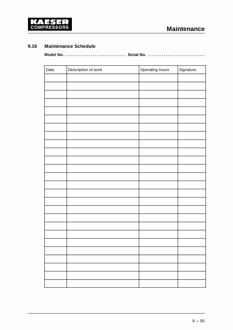
Maintenance
9 --- 55
9.16 Maintenance Schedule
Model No. Serial No.. . . . . . . . . . . . . . . . . . . . . . . . . . . . . . . . . . . . . . . . . . . . . . . . . . . . . . . . . . . .
Date Description of work Operating hours Signature
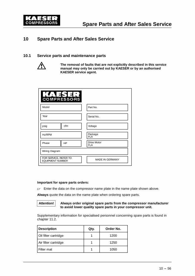
Spare Parts and After Sales Service
10 --- 56
10 Spare Parts and After Sales Service
10.1 Service parts and maintenance parts
The removal of faults that are not explicitly described in this servicemanual may only be carried out by KAESER or by an authorisedKAESER service agent.
Model
Year
psig cfm
Hz/RPM
Phase HP
Wiring Diagram
FOR SERVICE, REFER TOEQUIPMENT NUMBER
Part No.
Serial No.
Voltage
PackageFLA
Drive MotorFLA
MADE IN GERMANY
Important for spare parts orders:
� Enter the data on the compressor name plate in the name plate shown above.
Always quote the data on the name plate when ordering spare parts.
Always order original spare parts from the compressor manufacturerto avoid lower quality spare parts in your compressor unit.
Supplementary information for specialised personnel concerning spare parts is found inchapter 11.2.
Description Qty. Order No.
Oil filter cartridge 1 1200
Air filter cartridge 1 1250
Filter mat 1 1050
Attention!
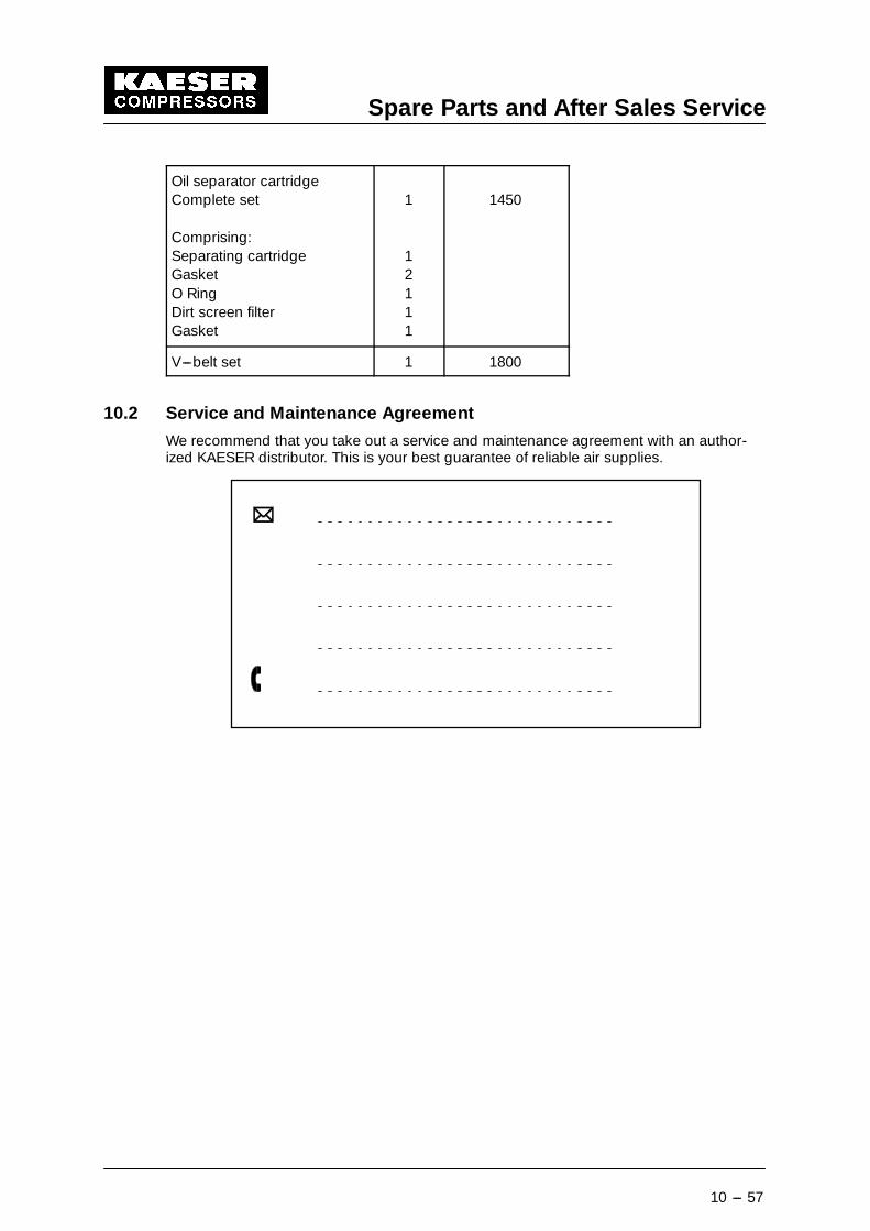
Spare Parts and After Sales Service
10 --- 57
Oil separator cartridgeComplete set
Comprising:Separating cartridgeGasketO RingDirt screen filterGasket
1
12111
1450
V---belt set 1 1800
10.2 Service and Maintenance Agreement
We recommend that you take out a service and maintenance agreement with an author-ized KAESER distributor. This is your best guarantee of reliable air supplies.
Appendix
11 --- 58
11 Appendix
11.1 Wiring Diagram
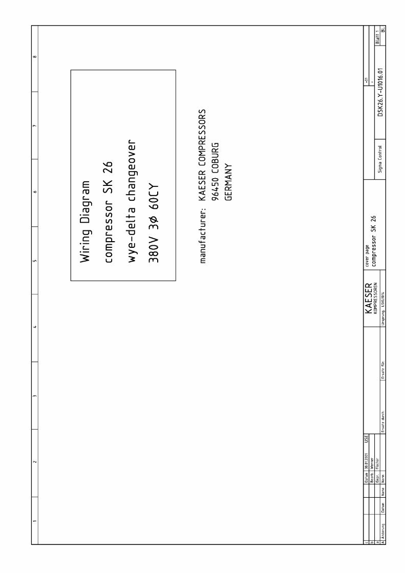
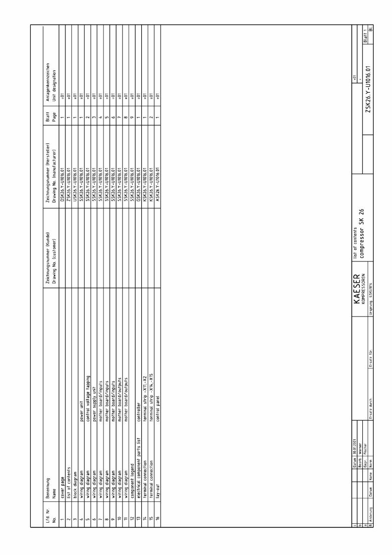
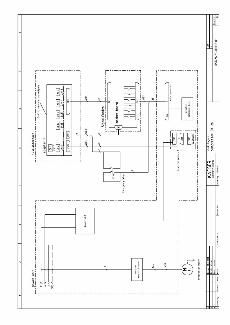
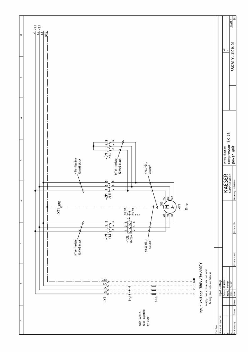
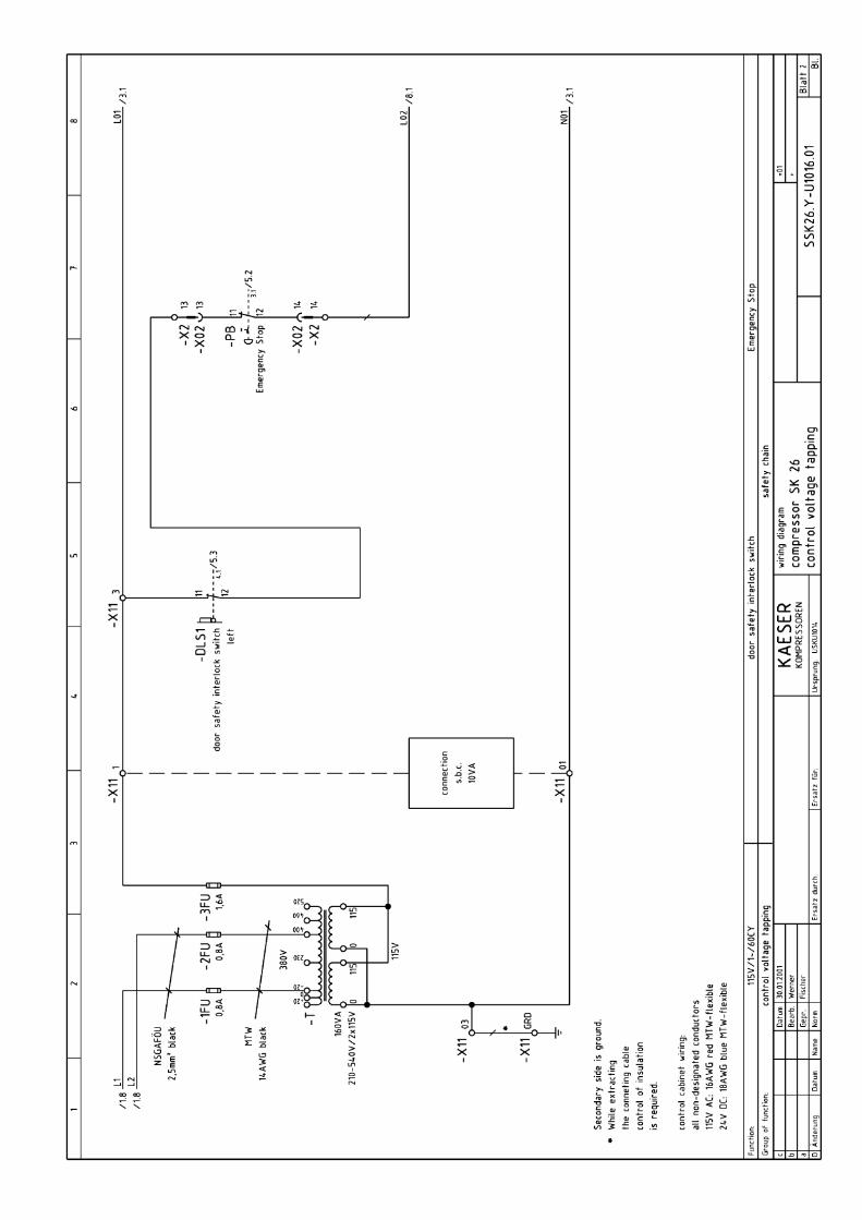
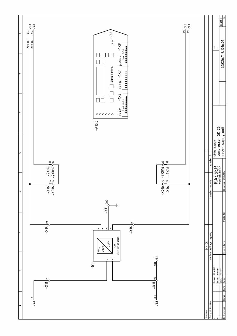
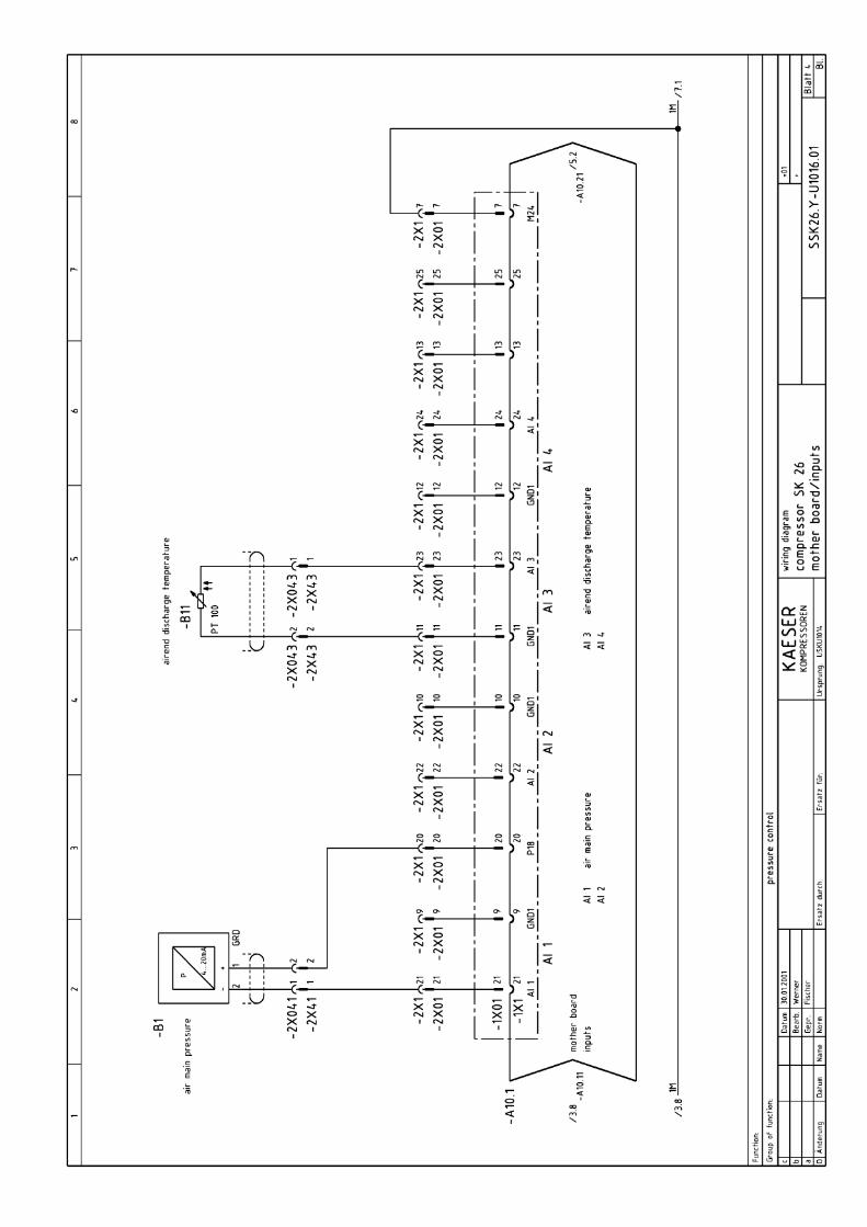
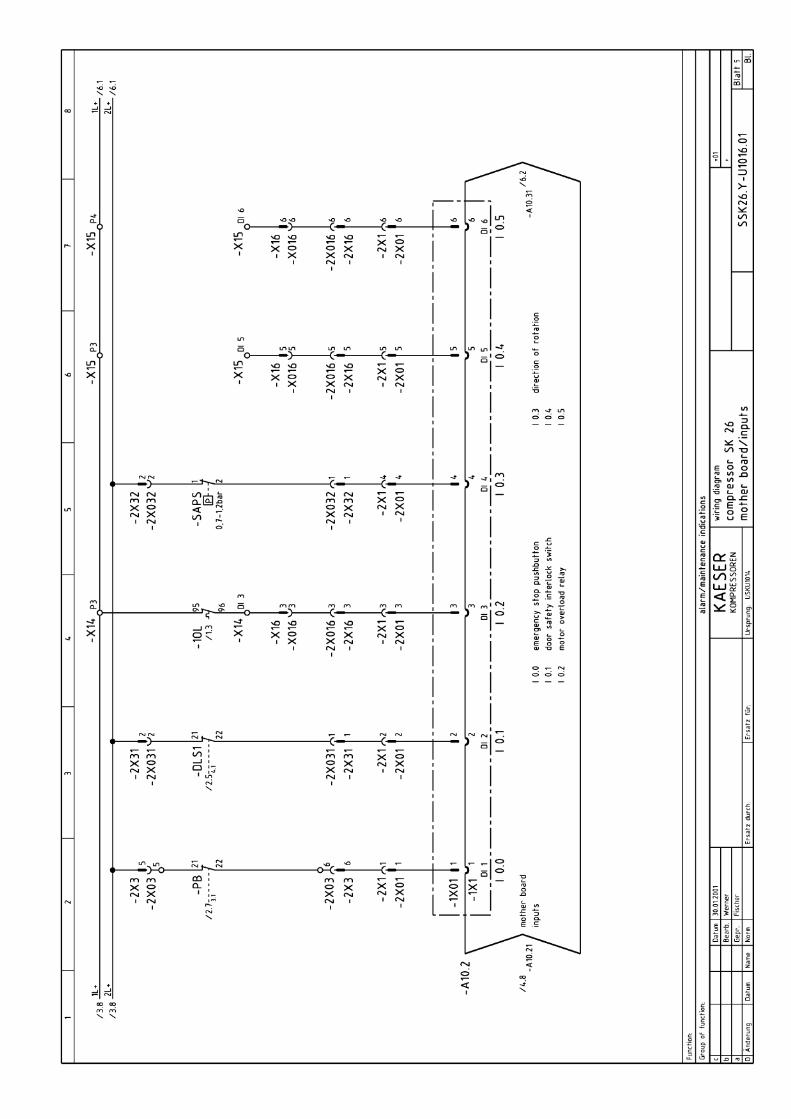
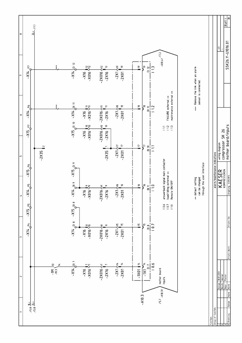
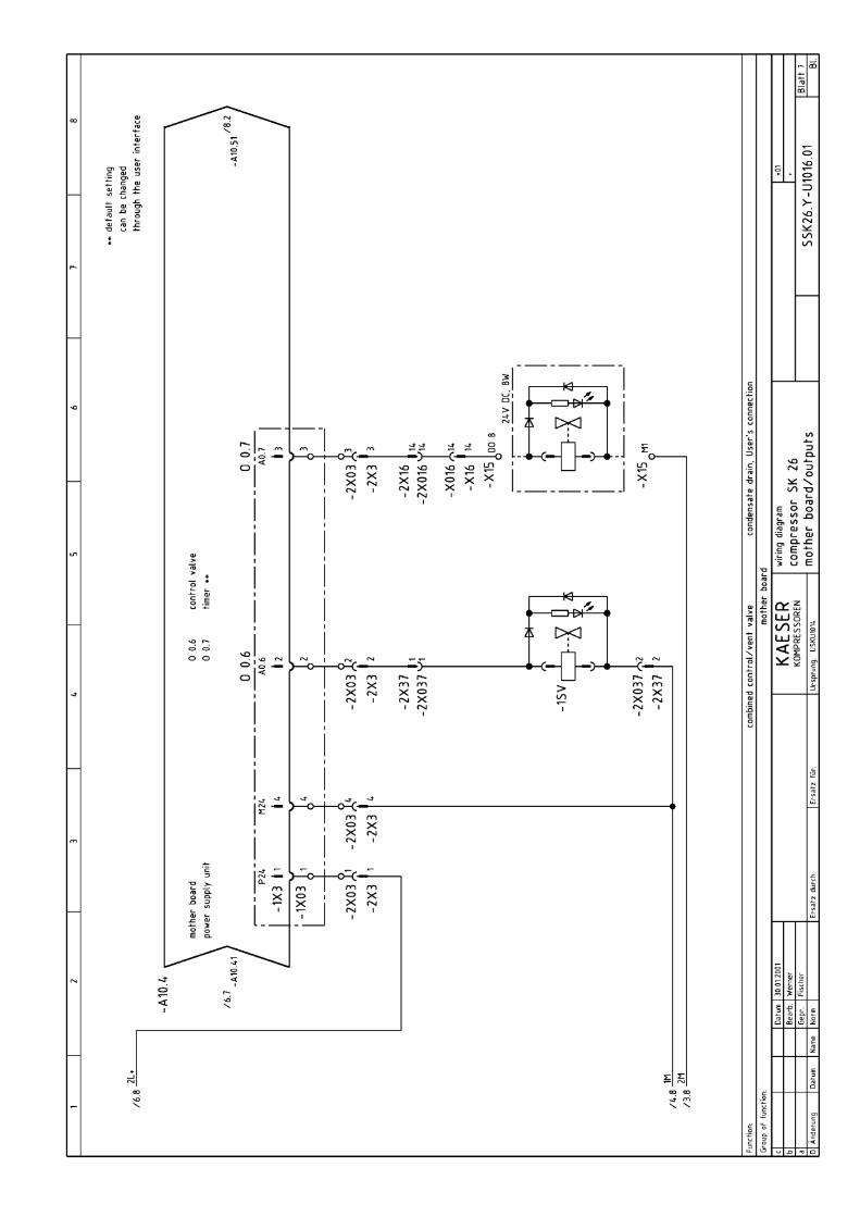
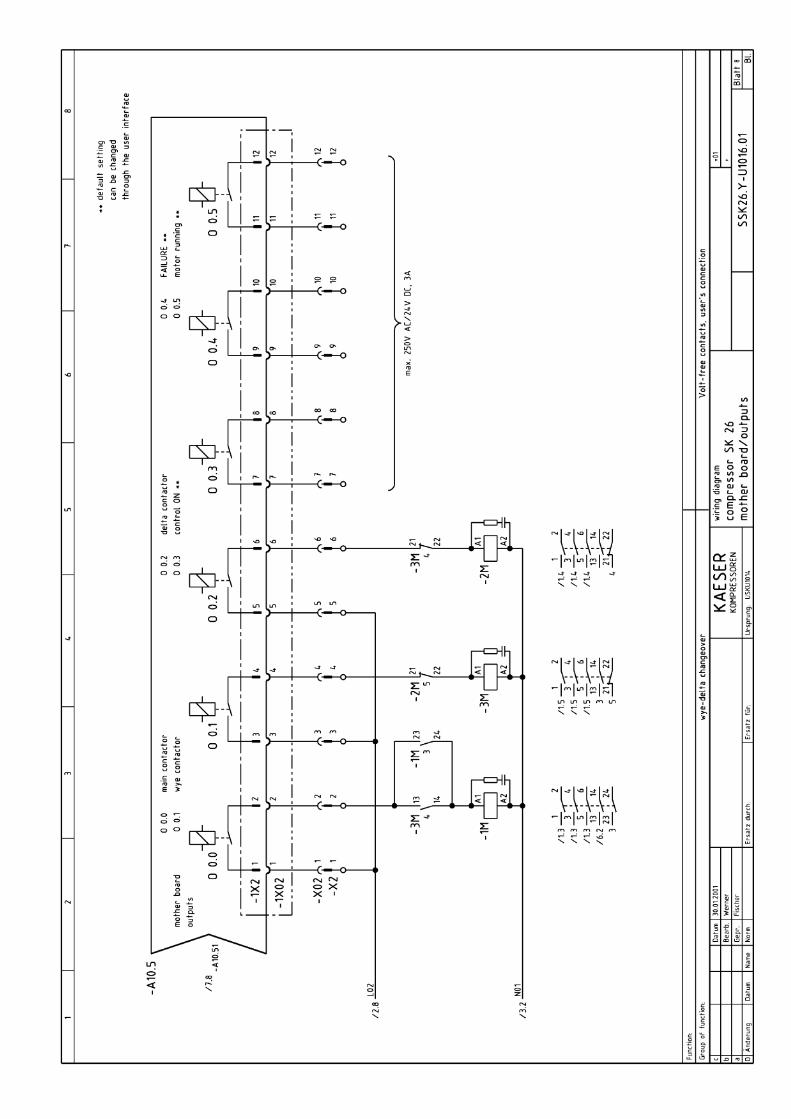
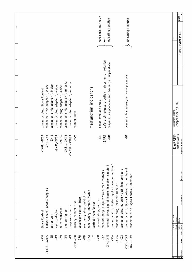
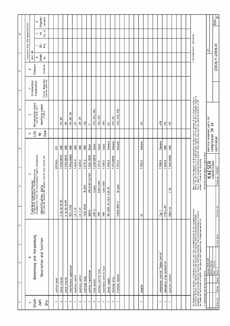
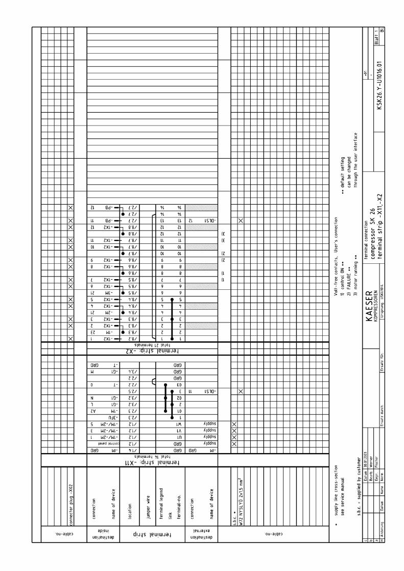
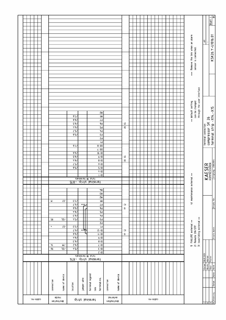
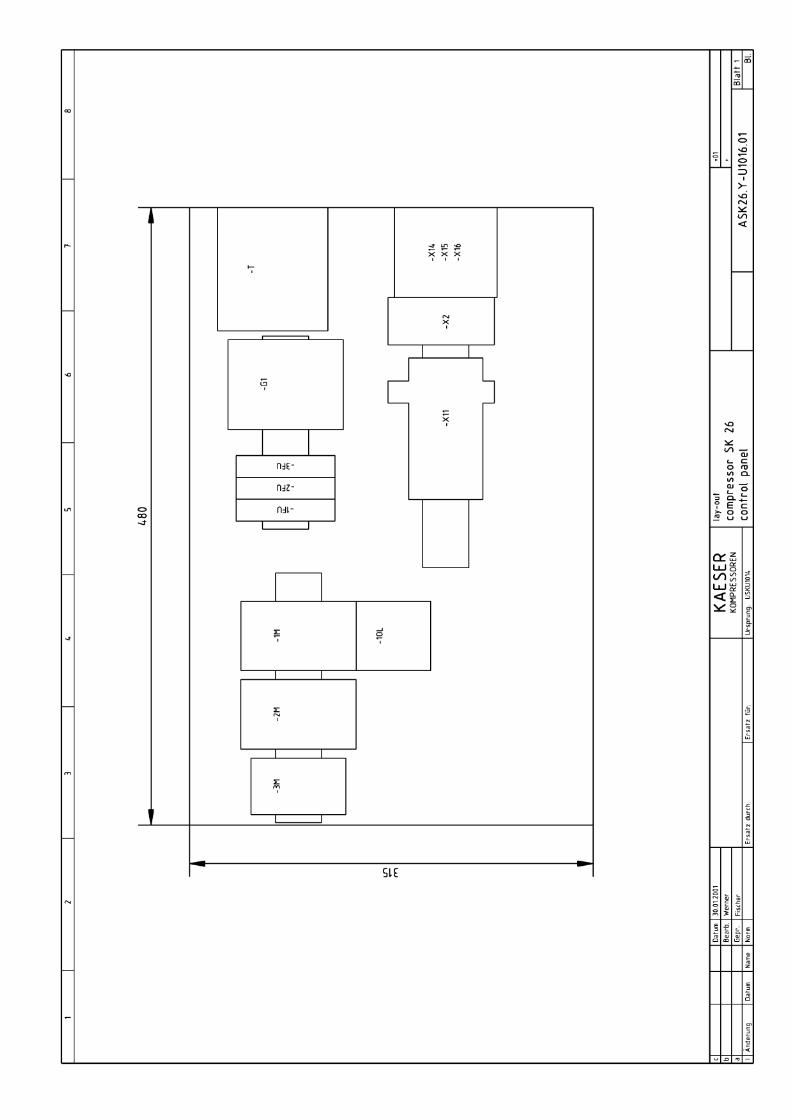
Appendix
11 --- 75
11.2 Spare Parts List
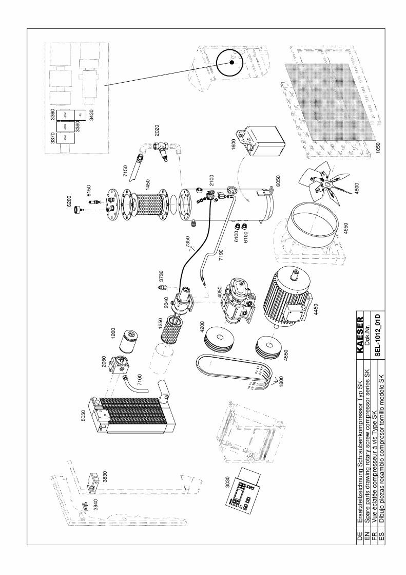
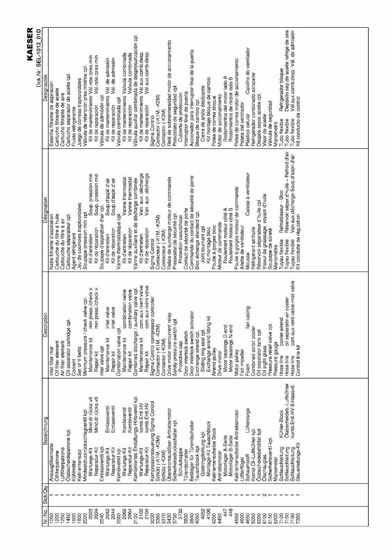
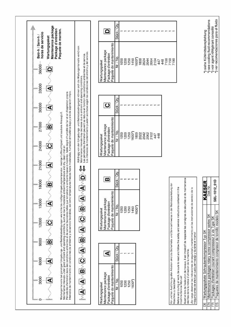
Related Documents