INSTRUCTION MANUAL MET200 Meteorological System Revision: 07/15 Copyright © 2015 Campbell Scientific Australia Pty Ltd

Welcome message from author
This document is posted to help you gain knowledge. Please leave a comment to let me know what you think about it! Share it to your friends and learn new things together.
Transcript

INS
TR
UC
TIO
N M
AN
UA
L
MET200 Meteorological System
Revision: 07/15
C o p y r i g h t © 2 0 1 5
C a m p b e l l S c i e n t i f i c A u s t r a l i a P t y L t d

Warranty
“Products manufactured by CSI are warranted by CSI to be free from defects in
materials and workmanship under normal use and service for twelve months
from the date of shipment unless otherwise specified in the corresponding
product manual. (Product manuals are available for review online at
www.campbellsci.com.au.) Products not manufactured by CSI, but that are
resold by CSI or one of its affiliates, are warranted only to the limits extended
by the original manufacturer. Batteries, fine-wire thermocouples, desiccant,
and other consumables have no warranty. CSI’s and its affiliates obligation
under this warranty is limited to repairing or replacing (at CSI’s option)
defective Products, which shall be the sole and exclusive remedy under this
warranty. The Customer assumes all costs of removing, reinstalling, and
shipping defective Products to CSI or the affiliate the goods were purchased
through. CSI will return such Products by surface carrier prepaid within the
continental United States of America. To all other locations, CSI will return
such Products best way CIP (port of entry) per Incoterms ® 2010. This
warranty shall not apply to any Products which have been subjected to
modification, misuse, neglect, improper service, accidents of nature, or
shipping damage. This warranty is in lieu of all other warranties, expressed or
implied. The warranty for installation services performed by CSI or its
affiliates such as programming to customer specifications, electrical
connections to Products manufactured by CSI, and Product specific training, is
part of CSI's product warranty. CSI EXPRESSLY DISCLAIMS AND
EXCLUDES ANY IMPLIED WARRANTIES OF MERCHANTABILITY
OR FITNESS FOR A PARTICULAR PURPOSE. CSI hereby disclaims,
to the fullest extent allowed by applicable law, any and all warranties and
conditions with respect to the Products, whether express, implied or
statutory, other than those expressly provided herein.”

Assistance
Products may not be returned without prior authorisation. The following
contact information is for Australian and International customers residing in
countries served by Campbell Scientific Australia Pty Ltd (CSA) directly.
Affiliate companies handle repairs for customers within their territories. Please
visit www.campbellsci.com.au to determine which Campbell Scientific
company serves your country.
When sending back equipment to CSA for repair or calibration, you will need
to follow the below procedure:
Contact CSA and obtain an RMA number for the items to be returned. This
RMA number allows CSA to track your device when received at our shipping
dock. CSA will create a ticket (http://helpdesk.campbellsci.com.au/) for this
repair/calibration so that it can be followed by all people involved in the
process (customer, administration, shipping, repair and application engineering
group)
Fill in an RMA form (including the RMA number provided) and
the decontamination form.
Email back the filled RMA form and Decontamination form through the
ticketing system.
Send the unit(s) to CSA with a printed copy of the RMA form and
decontamination form.
When shipping equipment back to CSA, please use the following delivery
address:
Campbell Scientific Australia
411 Bayswater Road
Garbutt QLD 4814
AUSTRALIA
Contact: Shipping Coordinator ([email protected])

i
Table of Contents
PDF viewers: These page numbers refer to the printed version of this document. Use the
PDF reader bookmarks tab for links to specific sections.
1. Introduction ................................................................ 1
1.1 Documentation ..................................................................................... 1 1.2 Component Parts .................................................................................. 1
2. What You Get With Your MET200 Weather Station.. 2
2.1 Standard Equipment ............................................................................. 2 2.2 Optional Equipment ............................................................................. 2
3. Installation .................................................................. 4
3.1 System Enclosure ................................................................................. 4 3.2 CM204 Cross-arm ................................................................................ 6 3.3 CS215-MET2 ....................................................................................... 6 3.4 03002-MET2 ........................................................................................ 7 3.5 SP-212-MET2 .................................................................................... 10 3.6 CS703-MET2 ..................................................................................... 11 3.7 CS106-MET2 ..................................................................................... 12 3.8 Sensor Connectors.............................................................................. 12 3.9 Final Installation Details .................................................................... 13
4. Powering the MET200 .............................................. 14
5. Establish Communications ..................................... 16
5.1 Using a Personal Computer running PC200W ................................... 16 5.2 Setting the MET200 Datalogger Clock .............................................. 18
6. Viewing and Collecting Measurements .................. 19
6.1 Viewing Real-time Public data table .................................................. 19 6.2 Collecting Recorded Data .................................................................. 20 6.3 Data Storage ....................................................................................... 21
6.3.1 Min15 Table ................................................................................ 22 6.3.2 Min30 Table ................................................................................ 23 6.3.3 Daily Table ................................................................................. 24 6.3.4 Additional Evapotranspiration Data tables ................................. 24
6.3.4.1 ET_Hourly Table .............................................................. 25 6.3.4.2 ET_Daily Table ................................................................ 25
6.3.5 NAN Values ................................................................................ 26 6.3.6 Data Table Storage Limits .......................................................... 27
7. MET200 Configuration Software ............................. 27
8. System Maintenance ................................................ 28
8.1 Enclosure............................................................................................ 28

Table of Contents
ii
8.2 Regular Inspection ............................................................................. 29 8.2.1 General ....................................................................................... 29 8.2.2 Sensors ....................................................................................... 29
8.2.2.1 Weekly ............................................................................. 30 8.2.2.2 Monthly ........................................................................... 30 8.2.2.3 Six-Monthly ..................................................................... 30 8.2.2.4 Yearly .............................................................................. 30 8.2.2.5 Every Two Years ............................................................. 30 8.2.2.6 Every Four to Five Years ................................................. 30
8.2.3 Power Supply ............................................................................. 30
9. Thank you ................................................................. 31
Appendix A. Troubleshooting ................................... A-1
A.1 Loss of Power .................................................................................. A-1 A.2 No Response from the Datalogger .................................................. A-1 A.3 Some NAN fields in the data tables ................................................ A-2 A.4 Hourly and Daily ET tables have no values written to table ........... A-2
Figures
FIGURE 3-1. Typical MET200-3M station mounting ................................... 4 FIGURE 3-2. Mounting the MET200 System Enclousre to a vertical pole .... 5 FIGURE 3-3. CM204 cross-arm mounted to vertical pole using CM210 cross-
arm to pole mounting bracket .......................................................... 6 FIGURE 3-4. CS215-MET2 mounted on a tripod mast .................................. 7 FIGURE 3-5. 03002 Wind Sentry attached to supplied mounting pipe via hose
clamp. ............................................................................................... 8 FIGURE 3-6. CM220 right angle bracket used to attach 03002 Wind Sentry
vertical mounting pipe to the 1.2m CM204 horizontal cross-arm.... 8 FIGURE 3-7. Installed 03002 Wind Sentry .................................................... 9 FIGURE 3-8. Installed SP-212 Pyranometer ................................................ 10 FIGURE 3-9. Installation Requirements for CS703-MET2 .......................... 11 FIGURE 3-10. MET200 Mil-spec connectors .............................................. 12 FIGURE 3-11. Diagram Showing MET200 Sensor Connections ................. 13 FIGURE 4-1. 10W solar panel and mounting bracket attached to a vertical
mast ................................................................................................ 14 FIGURE 4-2. Installing the 12V 7Ahr system battery .................................. 15 FIGURE 4-3. In-line power fuse needs to be connected for system to Power15 FIGURE 5-1. PakBus Address and Serial Number for MET200 stations are
located on the front of the internal connector cover plate. ............. 18 FIGURE 6-1. Screenshot of MET200 Public data table with all sensor options
configured on the weather station .................................................. 20 FIGURE 6-2. Collect Data Window in PC200W .......................................... 21 FIGURE 7-1. MET200 Configurator GUI .................................................... 27

Tables
TABLE 6-1. Public Table ............................................................................. 19 TABLE 6-2. Min 15 Table ........................................................................... 22 TABLE 6-3. Min30 Table ............................................................................ 23 TABLE 6-4. Daily Table .............................................................................. 24 TABLE 6-5. ET Hourly Table ...................................................................... 25 TABLE 6-6. ET Daily Table ........................................................................ 25 TABLE 6-7. MET200 Output Data based on system sensor configuration .. 26 TABLE 6-8. MET200 Data Table Storage Limits ........................................ 27

1
MET200 Meteorological System
1. Introduction Thank you for purchasing a Campbell Scientific MET200 Weather Station. We
recommend that you begin by reading this Installation Manual carefully before
attempting to assemble, set-up and use the weather station, as it contains
important information about siting, assembly and maintenance.
The manual also includes introductory information about setting up
communications with your weather station. Using this information you will be
able to start making measurements straight away.
1.1 Documentation
The documentation supplied with your MET200 Weather Station consists of
the following:
MET200 System Manual (this document)
Campbell Scientific Resource CD containing PC200W software
PC200W and the MET200 Configurator software are available to download
free of charge:
www.campbellsci.com.au/met200-support
1.2 Component Parts
Carefully unpack your MET200 shipment and check you have the following:
MET200 pre-wired System Enclosure
7Ahr Sealed Lead Acid Battery
10W Solar Panel and Bracket
Serial to USB Cable
1.2m galvanised sensor cross-arm with CM210 mounting bracket
Optional Components – only supplied if ordered with MET200 system
GM10 Mounting Pole or CM106B Tripod (if ordered)
CS215-MET2 Air Temperature and Relatvie Humidity Probe with 6
plate radiation shiled
03002-MET2 Wind Sentry with CM220 right angle mounting bracket
SP-212-MET2 Solar Radiation sensor with AL-100 Levelling plate
and CM225 mounting
CS703-MET2 Tipping Bucket Rain Gauge with CM240 Levelling
plate and mounting pole
CS106-MET2 Barometric Pressure sensor (installed in MET200
System Enclosure)

MET200 Meteorological System
2
2. What You Get With Your MET200 Weather Station
2.1 Standard Equipment
MET200 Core Unit consisting of:
o Pre-wired fibreglass enclosure with integral CR200X,
rechargeable sealed lead acid battery supply unit with in-line
power fuse, surface mount antenna and antenna ground
plane, pre-wired mil-spec connectors
o 10W Solar Panel and solar panel mounting bracket
o 17394 USB-Serial Cable
o CM204 1.2m galvanised instrument cross-arm with CM220
mounting bracket
o Resource CD containing PC200W datalogger software.
Please note, PC200W and the MET200 Configurator
Software can be downloaded from the following webpage:
http://www.campbellsci.com.au/met200-support
2.2 Optional Equipment
-3M Mounting Option consisting of:
o GM10 3 metre galvanised mounting pole with lightning
protection kit
-TPK Mounting Option consisting of:
o CM106B galvanised tripod with guy wire kit and lightning
protection kit
-IP Communication Option consisting of:
o Intelimax modem
o RS232 Intelimax Cable
o SMA to FME Adapter
CS215-MET2 Sensor consisting of:
o CS215 Air Temperature and Relative Humidity Probe
o RAD06 6 Plate Radiation Shield
03002-MET2 Sensor consisting of:
o 03002 Wind Sentry
o 17953 Nu-Rail Mounting Bracket
SP-212-MET2 Sensor consisting of:
MET200 Meteorological System
3
o SP-212 Solar Radiation Sensor
o A100 Solar Sensor Levelling Plate
o CM225 Solar Sensor Mounting Bracket
CS703-MET2 Sensor consisting of:
o CS703 Tipping Bucket Rain Gauge
o CM240-KT Levelling plate and mounting pole
CS106-MET2 Sensor consisting of:
o CS106 (PTB110) Barometric Pressure sensor (in MET200
enclosure)
The MET200 Weather Station is a complete turnkey system that is supplied
ready programmed for immediate use, configured to measure the sensors
ordered with the system. The specific sensor configuration of your MET200
system will determine the active data table outputs (See Section 6). Campbell
Scientific PC200W datalogger software can be used for a simple direct
connection to the MET200 Weather Station via the supplied Serial-USB Cable
(see Section 5.1 for further information on configuring PC200W software for
communicating with a MET200 system). Should additional compatible sensors
be ordered for your MET200 system at a later date, the MET200 Configurator
Software can be used to easily reconfigure your MET200 system (See Section
7).

MET200 Meteorological System
4
3. Installation
3.1 System Enclosure
When a MET200 Weather Station is ordered with the -3M Mounting Option,
the system comes supplied with a GM10 3 metre galvanised mounting pole
with lightning protection kit. The -3M mounting option requires a concrete
footing of approximately 600 mm deep, as shown in FIGURE 3-1.
FIGURE 3-1. Typical MET200-3M station mounting

MET200 Meteorological System
5
To install the MET200 enclosure and sensors you will require:
A tape measure
A spirit level
An adjustable spanner
A flat blade screwdriver
A compass (for wind direction orientation of 03002-MET2)
Cable Ties for securing sensor cables
Laptop computer
PC200W software installed and configured on user laptop
Rapid set pre-mix concrete (or similar) and water if installing CS703-
MET2
Mount the MET200 System Enclosure onto the GM10 pole (-3M option) or
CM106B tripod (-TPK option) using the supplied U-bolts, ensuring the top of
the enclosure is approximately 1 metre from the ground. Using an adjustable
spanner, secure the enclosure by tightening the U-bolt nuts onto the flat and
spring washers as shown in FIGURE 3-2 below. U-bolts (supplied) are
required at the top and bottom to fully secure the enclosure.
FIGURE 3-2. Mounting the MET200 System Enclousre to a vertical pole

MET200 Meteorological System
6
3.2 CM204 Cross-arm
Mount the CM204 (1.2m) cross-arm to the vertical pole or mast as shown in
FIGURE 3-3 using the supplied CM210 cross-arm to pole mounting bracket.
The CM210 bracket is supplied with U-bolts, lock washers and nuts.
FIGURE 3-3. CM204 cross-arm mounted to vertical pole using CM210 cross-arm to pole mounting bracket
3.3 CS215-MET2
The CS215-MET consists of a CS215 combined air temperature and relative
humidity probe, and a RAD-06 6 plate non-aspirated radiation shield. Install
the RAD-06 radiation shield to the GM10 pole or CM106 tripod mast above
the system enclosure using the U-bolt attached to the RAD-06 shield. Ensure
the U-bolt on the RAD-06 is mounted on the pole or mast at a height of
approximately 1.8 metres. Loosen the RAD-06 gland and insert the CS215
sensor into the gland as shown in FIGURE 3-4 then tighten the gland to secure
the CS215 sensor in place.

MET200 Meteorological System
7
FIGURE 3-4. CS215-MET2 mounted on a tripod mast
For optimum cable management, loop the CS215 cable and secure with cable
ties as shown in FIGURE 3-4.
3.4 03002-MET2
The 03002-MET2 consists of an RM Young 03002 Wind Sentry sensor, a 12
inch long mounting pipe and a CM220 right-angle mounting bracket. Attach
the mounting pipe to the 03002 wind sentry, using a flat blade screwdriver to
temporarily tighten the hose clamp on the 03002 so it compresses onto the
mounting pipe (FIGURE 3-5).

MET200 Meteorological System
8
FIGURE 3-5. 03002 Wind Sentry attached to supplied mounting pipe via hose clamp.
Next, attach the mounting pipe to the station cross-arm using the CM220
bracket as shown in FIGURE 3-6.
FIGURE 3-6. CM220 right angle bracket used to attach 03002 Wind Sentry vertical mounting pipe to the 1.2m CM204 horizontal cross-arm.
Ensure the cross-arm of the 03002 sensor is oriented North-South with the
wind vane to the North.
Alignment of the wind vane is now required. Two people are recommended for
initial wind vane alignment, one to adjust the instrument position and the other
to observe the wind direction reading on a laptop connected to the MET200
system.

MET200 Meteorological System
9
To align the wind vane, select a known azimuth reference point on the horizon.
Next, sighting down the wind vane centreline, point the wind vane
counterweight at the reference point on the horizon. While holding the vane in
position, slightly loosen the hose clamp to allow you to slowly turn the base of
the wind vane until the wind direction reading displays the correct azimuth
value. Tighten the hose clamp to fix the sensor into position.
FIGURE 3-7. Installed 03002 Wind Sentry

MET200 Meteorological System
10
3.5 SP-212-MET2
The SP-212-MET consists of an SP-212 pyranometer, an AL-100 solar
levelling base and a CM225 (P/N 17906) solar sensor mounting bracket. The
pyranometer should be mounted such that no shadows or reflections are cast on
the sensor by the weather station mounting equipment or other sensors. The
sensor should be mounted with the cable pointing towards the nearest magnetic
pole, e.g. in the Southern Hemisphere point the cable towards the South Pole.
Firstly, mount the CM225 to the cross-arm using the supplied U-bolt, nuts and
washers. Next, place the SP-212 pyranometer in the centre of the AL-100
levelling base, and loosely mount the AL-100 to the CM225 bracket. Turn the
levelling screws as required on the AL-100 to bring the level bubble within the
ring. Once level, tighten the mounting screws on the underside of the CM225
bracket to secure the assembly in its final position, giving a final check of the
level bubble to ensure the pyranometer is still correctly levelled. Route the
cable along the underside of the cross-arm to the main weather station mast,
and down the mast to the main MET200 system enclosure. Secure the cable
with cable ties.
FIGURE 3-8. Installed SP-212 Pyranometer

MET200 Meteorological System
11
3.6 CS703-MET2
The CS703-MET2 consists of a CS703 (TB6) tipping bucket rain gauge and a
CM240-KT levelling base and mounting pole. The CM240 base helps level the
rain gauge, ensuring a more accurate measurement. The CM240 base attaches
to the supplied 1 m mounting pole which should be concreted into the ground,
as shown in FIGURE 3-9.
FIGURE 3-9. Installation Requirements for CS703-MET2
The rain gauge should be levelled after mounting. To level, remove the housing
assembly from the base by loosening the three housing screws and lifting the
housing upward. Adjust the three nuts on the CM240 bracket to level the gauge
– a bullseye level is mounted on the rain gauge base to facilitate levelling.
Whilst the housing assembly is removed, ensure to remove the rubber shipping
band and cardboard packing securing the tipping bucket assembly. Tip the
bucket mechanism several times to ensure the tipping mechanism is moving
freely. Replace the housing assembly and tighten the three screws to secure the
housing to the base.

MET200 Meteorological System
12
3.7 CS106-MET2
The CS106-MET consists of a CS106 barometric pressure sensor which, if
ordered with a MET200 Core Unit, is supplied pre-installed inside the MET200
System Enclosure. The CS106-MET requires no installation by the user.
3.8 Sensor Connectors
All external sensors supplied with MET200 systems have mil-spec connectors
for connecting to the underside of the system enclosure (see FIGURE 3-10). A
diagram on the inside of the system enclosure (see FIGURE 3-11) indicates
where each sensor connects to the enclosure. The system has also been
designed with unique pin configurations for each sensor to ensure a connector
cannot be inserted into the wrong mating connector. To attach a sensor to its
mating connector, unscrew the protective cap, then gently insert the female
sensor connector into its mating male connector on the underside of the
enclosure. Align the vertical notch on both the female and male connectors,
which will allow the connectors to mate together. Then screw the sensor
connector onto the enclosure connector to ensure a secure fitting.
FIGURE 3-10. MET200 Mil-spec connectors

MET200 Meteorological System
13
FIGURE 3-11. Diagram Showing MET200 Sensor Connections
3.9 Final Installation Details
Secure grounding wire and all sensor cables to the mast and cross-arm using
cable ties. It is essential to secure any excess sensor cables with cable ties.
Unsecured cables can blow around in the wind and may cause the wires inside
to break, often without any external signs of damage. Ensure that the protective
caps are kept on any enclosure connectors that are not used to ensure
connectors are water tight.
MET200 Meteorological System
14
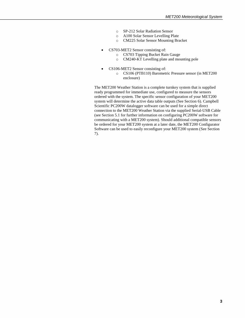
4. Powering the MET200 MET200 systems are supplied with a 10W solar panel and 12V 7Ahr SLA
Battery for powering the system.
The 10W solar panel is supplied pre-mounted to a solar panel mounting bracket
(FIGURE 4-1). Mount the solar panel bracket to the main pole or mast using
the mounting bracket U-bolt, and angle the solar panel to suit the installation
location. In the Southern hemisphere, ensure solar panel is mounted facing
North.
FIGURE 4-1. 10W solar panel and mounting bracket attached to a vertical mast
To protect the MET200 Core Unit in shipping, the 12V battery is left out of the
enclosure and requires installation when the system is installed. Simply place
the battery into the battery holder inside the MET200 System Enclosure, and
use the supplied velcro strap to secure the battery to the bracket (FIGURE 4-2).
To power the system, simply attach the black (-ve) and red (+ve) spade
connectors to the battery, observing the correct polarity, and ensure the inline
power fuse on the DIN Rail terminals is connected (FIGURE 4-3). When the
system is powered up, the red Scan light on the CR200X datalogger in the
system enclosure will light up every 10 seconds to indicate the system program
in running.

MET200 Meteorological System
15
FIGURE 4-2. Installing the 12V 7Ahr system battery
FIGURE 4-3. In-line power fuse needs to be connected for system to Power
Congratulations, your MET200 system is now installed and powered up
ready for operation.

MET200 Meteorological System
16
5. Establish Communications
5.1 Using a Personal Computer running PC200W
Your MET200 Station comes ready configured for the sensor options ordered
with the system. Supplied with your MET200 system is a Resource CD which
contains the PC200W datalogger support software package. Once installed on
your PC, this windows program will allow you to communicate with the
MET200 weather station, view the MET200 station data and collect data from
the station.
Prior to installing PC200W on your PC, install the driver for the Serial-USB
cable supplied with your MET200 System. A CD is supplied with the Serial-
USB cable. Should your PC not have a CD Rom Drive, the driver for this cable
can be downloaded from the following web page:
www.sabrent.com/downloads.php
The model number Serial-USB cable supplied with the MET200 system is
Sabrent CB-FTDI. Once the Sabrent driver has been successfully installed,
connect the USB end of the Serial-USB cable into a USB port on your PC, and
it should be assigned a ComPort number by Windows. Take note of this
ComPort number as it will be required in the setup procedure for PC200W.
Proceed to installing PC200W.
Install PC200W onto your computer by following the instructions on screen.
Once installed, open PC200W on your computer and you will be presented
with the EZSetup Wizard. Following the onscreen prompts, configure your
MET200 system connection as follows:
PC200W EZSetup Settings for MET200
Communication Setup
Choose the CR200 Series datalogger from the scrolling list
Datalogger name: Enter a name up to 12 digits, e.g. MET200 (CR200X is
default but can be overwritten)
CLICK NEXT >>
COM Port: Select the ComPort that your Serial-USB cable was assigned by
Windows (e.g. COM4). Please note, when connecting to a different USB port
on your computer, Windows may assign different ComPort numbers, so it is
best to always connect your Serial-USB cable to the same USB port.
COM Port Communication Delay: 00 Seconds
CLICK NEXT >>
Datalogger Settings
Baud Rate: 9600

MET200 Meteorological System
17
Security Code:
Extra Response Time: 00 Seconds
CLICK NEXT >>
Setup Summary
CLICK NEXT >>
Communication Test
Check Yes
CLICK NEXT >>
If communication is unsuccessful then
a) ensure power is switched on (see Section 4)
b) ensure you have the correct ComPort selected for your Serial-USB cable
c) contact Campbell Scientific Australia
Datalogger Clock
Check the dataloggers clock and reset if required.
CLICK NEXT >>
Send Program
Do not send a program. Your MET200 station comes pre-configured with a
measurement program.
CLICK NEXT >>
Wizard Complete
CLICK NEXT >>
If you have more than one MET200 weather station, you will have to set up a
different datalogger (with a different, unique name) for each station to ensure
the data from each station is collected properly. By default MET200 stations
ordered individually are shipped with PakBus Address 1. When multiple
MET200 stations are purchased on the same order, the PakBus Address for
each MET200 station on the order will be unique and set at factory prior to
shipping. You can check the PakBus Address configured for your MET200
station by checking the PakBus Address label located on the front of the
connector cover plate inside the system enclosure (FIGURE 5-1).

MET200 Meteorological System
18
FIGURE 5-1. PakBus Address and Serial Number for MET200 stations are located on the front of the internal connector cover plate.
5.2 Setting the MET200 Datalogger Clock
The CR200X datalogger used in the MET200 weather station contains the
system program in non-volatile flash memory, and this will be retained even
when the main battery power supply is removed (e.g. in shipping). The clock
(data and time) settings are also battery-backed, and will be retained when the
datalogger is powered down. Although your MET200 datalogger will have the
data and time set before dispatch (to AEST time), you should check the current
settings to ensure that they conform to your specific location requirements.
You can synchronise the MET200 datalogger clock with your computer clock
by pressing the ‘Set Clock’ button on the PC200W main connect screen when
connected to the datalogger. PC200W will communicate with the CR200X
Series Datalogger and set its clock time to match your computer time, so make
sure your computer clock is correct prior to setting the MET200 system clock.
MET200 Meteorological System
19
6. Viewing and Collecting Measurements
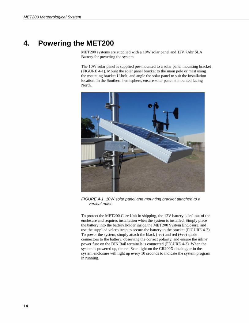
6.1 Viewing Real-time Public data table
Now that you have established communications and set the MET200
datalogger clock to local time (via PC200W), you are ready to view the
measurements being obtained by your MET200 weather station. Measurements
can be easily viewed in real-time on your computer via direct connection to the
datalogger using PC200W. Real-time measurements from the sensors are
stored as publicly accessible variables located in the Public data table:
TABLE 6-1. Public Table
Variable Name Description
Record No Data Record Number in Public data table
Time Stamp Data Record Timestamp
MET200_Dec Ignore this value – used for diagnostic purposes only
Longitude Longitude of the station (See Section 7)
Latitude Latitude of the station (See Section 7)
Altitude Altitude above MSL of the station (See Section 7)
batt_volt Sample battery voltage
AirTemp Sample Air Temperature
RH Sample Relative Humidity
DewPoint Calculated Dew Point Temperature
AppTemp Calculated Apparent Temperature
DeltaT Calculated Delta T
WS_ms Sample Wind Speed in metres per second
WS_kmh Sample Wind Speed in kilometres per hour
WindDir Sample Wind Direction
Solar_Wm2 Sample Solar Radiation in Watts per square metre
Solar_MJ Sample Solar Radiation in Mega Joules per square
metre
Rain_mm Sample Rainfall in millimetres
Rain_Since_9am Total Rainfall since 9am
Rain_Intensity Rain Intensity in millimetres per hour based on 5
minute running sample period
BP_hPa Sample Barometric Pressure in hectopascal

MET200 Meteorological System
20
To monitor the Public data table in real-time:
1. Connect your PC to the CR200X datalogger in the MET200 system
enclosure using the supplied Serial-USB cable
2. Open up PC200W
3. Click on “Setup/Connect” tab on the main PC200W screen
4. Click on the “Connect” button to initiate communication with the
datalogger
5. Once connected, click on the “Monitor Values” tab on the main
PC200W screen
6. Click on the “Add” button
7. From the Add Selection box, click on the “Public” Table
8. Click “Paste” to paste all the Public variables into the Monitor Data
Screen.
9. If a warning appears saying “Please select a cell to paste the selection
into”, hit OK, then select the top left cell in the Monitor Data tab, then
click “Paste” in the Add Selection box.
10. You can observe the Public variables changing every 10 seconds (you
will see Record Number increment).
A typical screenshot for the MET200 Weather Station Public table is shown in
FIGURE 6-1.
FIGURE 6-1. Screenshot of MET200 Public data table with all sensor options configured on the weather station
6.2 Collecting Recorded Data
To initiate data collection, click on the “Collect Data” tab in the main PC200W
window. In the Collect Data window you will be given the option to collect
data from the datalogger by clicking the “Start Data Collection” tab. You can
configure what data to collect and where to output the data to.
Irrespective of MET200 station sensor configuration, you should choose to
collect data from all data tables except the Public and Status tables, so in total 6
tables should be ticked (Bkp, Daily, ET_Daily, ET_Hourly, Min15, Min30) as
shown in FIGURE 6-2. Whether these tables are populated with data will
depend on the specific sensor configuration of your MET200 station.

MET200 Meteorological System
21
FIGURE 6-2. Collect Data Window in PC200W
In the Collect Data window, you can choose to collect:
New data from datalogger (Append to data files) – this is the normal
mode of operation
All data from datalogger (Overwrite data files)
The default file output location for data files is usually
C:\Campbellsci\PC200W\
To change the default file output location for a particular data table, highlight
the table and then select the “Change Table’s Output File” tab. This will open a
window where you can change the File name and output location for the file.
Click “Save” to save any changes you make.
All data files collected from a MET200 station are comma separated values
(CSV) files with a .dat file extension. These files can be opened in standard
software packages such as Microsoft Excel, or you can view data using the
View Software package built into PC200W (Tools >> View).
6.3 Data Storage
There are three standard data tables in a MET200 weather station, a 15 minute
table (Min15), 30 minute table (Min30) and a daily data table (Daily). In
addition to these standard tables, two Evapotranspiration (ET) data tables
(ET_Hourly and ET_Daily) will be populated with data only when the
MET200 system is configured to measure air temperature and relative humidity
(CS215-MET2), wind speed and direction (03002-MET2) and solar radiation
(SP-212-MET2).

MET200 Meteorological System
22
Another data table containing station configuration information (Bkp) should
be collected, but this data is only meaningful to a Campbell Scientific
Application Engineer for system diagnostic purposes.
The specific sensor configuration of a MET200 system will determine the data
table outputs. Data tables in the MET200 are structured as follows:
6.3.1 Min15 Table
The Min15 data table provides the following data at 15 minute resolution:
TABLE 6-2. Min 15 Table
Variable Description Units
Timestamp: Timestamp of data yyyy-mm-dd
hh:mm:ss
Record Data Record ID INT
Batt_volt_Min Minimum battery voltage Volts
AirTemp_Avg Average Air Temperature °C
RH_Avg Average Relative Humidity %
DewPoint_Avg Average Dew Point Temp °C
DeltaT_Avg Average Delta T °C
AppTemp_Avg* Average Apparent Temp °C
WS_kmh_Avg Mean Hz Wind Speed km/hr
WindDir Unit Vector Mean Wind
Direction
Degrees
SigmaTheta Standard deviation of Wind
Direction
Degrees
Solar_Wm2_Avg Average Solar Radiation W/m2
Rain_mm_Tot Total 15 minute Rainfall mm
Rain_Since_9am Total Rainfall since 9am mm
Rain_Intensity Rainfall Intensity (5 min
running period)
mm/hr
BP_hPa_Avg Average Barometric Pressure hPa
*Apparent Temp data only available when the CS215-MET2 and 03002-MET2
sensors are configured on a MET200 system, otherwise NAN will be reported
for AppTemp.

MET200 Meteorological System
23
6.3.2 Min30 Table
The Min30 data table provides the following data at 30 minute resolution:
TABLE 6-3. Min30 Table
Variable Description Units
Timestamp: Timestamp of data yyyy-mm-dd
hh:mm:ss
Record Data Record ID INT
Batt_volt_Min Minimum battery voltage Volts
AirTemp_Avg Average Air Temperature °C
RH_Avg Average Relative Humidity %
DewPoint_Avg Average Dew Point Temp °C
DeltaT_Avg Average Delta T °C
AppTemp_Avg* Average Apparent Temp °C
WS_kmh_Avg Mean Hz Wind Speed km/hr
WindDir Unit Vector Mean Wind Direction Degrees
SigmaTheta Standard deviation of Wind
Direction
Degrees
Solar_Wm2_Avg Average Solar Radiation W/m2
Rain_mm_Tot Total 30 minute Rainfall mm
Rain_Since_9am Total Rainfall since 9am mm
BP_hPa_Avg Average Barometric Pressure hPa
*Apparent Temp data only available when the CS215-MET2 and 03002-MET2
sensors are configured on a MET200 system, otherwise NAN will be reported
for AppTemp.

MET200 Meteorological System
24
6.3.3 Daily Table
The Daily data table provides the following data at daily resolution, output at
midnight:
TABLE 6-4. Daily Table
Variable Description Units
Timestamp: Timestamp of data yyyy-mm-dd
hh:mm:ss
Record Data Record ID INT
Batt_volt_Min Minimum battery voltage Volts
AirTemp_Max Maximum Air Temperature °C
AirTemp_Min Minimum Air Temperature °C
RH_Max Maximum Relative Humidity %
RH_Min Minimum Relative Humidity %
DewPoint_Max Maximum Dew Point Temp °C
DewPoint_Min Minimum Dew Point Temp °C
WS_kmh_Max Maximum Wind Speed km/hr
WS_kmh_Min Maximum Wind Speed km/hr
Solar_MJ_Tot Total Solar Radiation MJ/m2
Rain_mm_Tot Total 24hr Rainfall mm
BP_hPa_Max Maximum Barometric Pressure hPa
BP_hPa_Min Minimum Barometric Pressure hPa
6.3.4 Additional Evapotranspiration Data tables
If a MET200 system has the CS215-MET2, 03002-MET2 and SP-212-MET2
sensors configured on the system, in addition to the three standard data tables
listed above, ET_Hourly and ET_Daily data tables will also be populated with
data. If the MET200 system ordered does not have the required measurements
for ET calculation as described above, the ET data tables will not be populated
with data.

MET200 Meteorological System
25
6.3.4.1 ET_Hourly Table
TABLE 6-5. ET Hourly Table
Variable Description Units
Timestamp: Timestamp of data yyyy-mm-dd hh:mm:ss
Record Data Record ID INT
AirTemp_Avg Average Air Temperature °C
RH_Avg Average Relative Humidity %
WS_ms_Avg Average Wind Speed m/s
Solar_Wm2_Avg Average Solar Radiation W/m2
ETo Hourly Evapotranspiration mm
6.3.4.2 ET_Daily Table
TABLE 6-6. ET Daily Table
Variable Description Units
Timestamp: Timestamp of data yyyy-mm-dd hh:mm:ss
Record Data Record ID INT
AirTemp_Max Maximum Air Temperature °C
AirTemp_TMx Time of Maximum Air
Temperature
yyyy-mm-dd hh:mm:ss
AirTemp_Min Minimum Air Temperature °C
AirTemp_TMin Time of Minimum Air
Temperature
yyyy-mm-dd hh:mm:ss
RH_Max Maximum Relative
Humidity
%
RH_Min Minimum Relative Humidity %
WS_ms_Avg Average Wind Speed m/s
Solar_Wm2_Tot Total Solar Radiation MJ/m2
ETo Daily Evapotranspiration mm

MET200 Meteorological System
26
6.3.5 NAN Values
The MET200 system is pre-programmed to output NAN values in the data
columns of any sensors that are not present on the system. If columns in a data
table show NAN values, it is advisable to firstly visually confirm which
sensors you have connected into the MET200 system using the connector
diagram on the inside of the enclosure as a guide, and compare this to the
MET200 output data chart (TABLE 6-7) to confirm what measurements the
system should be reporting. If there is a discrepancy, then you can use the
MET200 Configurator software (See Section 7) to check the current MET200
system configuration and change the configuration if required. Since MET200
sensor configuration is pre-configured at factory prior to shipping, changes to
the sensor configuration using the MET200 Configurator software should only
be required if additional sensors (not ordered with the original system) are later
added to the system.
As an example, Hourly and Daily Evapotranspiration will only be output if the
CS215-MET2, 03002-MET2 and the SP-212-MET are all present on the
MET200 weather station.
TABLE 6-7. MET200 Output Data based on system sensor configuration
CS215-MET2 03002-MET2 SP-212-MET2 CS703-MET2 CS106-MET2
Air Temperature
Relative Humidity
Dew Point Temperature
Delta T
Wind Speed
Wind Direction
Sigma Theta
Solar Radiation
(W/m2)
Solar Radiation
(MJ/m2)
Total Rainfall
Rain Since 9am
Rainfall Intensity
Barometric
Pressure
Apparent Temperature
Hourly Evapotranspiration
Daily Evapotranspiration

MET200 Meteorological System
27
6.3.6 Data Table Storage Limits
The data storage limits for MET200 weather stations are shown in TABLE 6-8.
All data tables are configured for ring memory, meaning once the table storage
limit is reached, the oldest data in the table will be overwritten.
TABLE 6-8. MET200 Data Table Storage Limits
Table Name Storage Limit (Days)
Min15 50
Min30 50
Daily 120
ET_Hourly 50
ET_Daily 120
7. MET200 Configuration Software MET200 systems are supplied from Campbell Scientific pre-configured for
measuring the sensor suite ordered with the system. However, site specific
location information required for ET data calculation (Altitude, Latitude,
Longitude) must be user-configured in the MET200 if the sensor configuration
supports ET output. This configuration is done through the MET200
Configurator software GUI, downloadable from the following web page:
https://www.campbellsci.com.au/met200-support
Download and install the MET200 Configurator software on your PC, then
open the software and you will be presented with the GUI interface as shown in
FIGURE 7-1.
FIGURE 7-1. MET200 Configurator GUI

MET200 Meteorological System
28
Select the appropriate ComPort on your PC to connect to the MET200 system
via the supplied Serial-USB cable. Ensure Baud Rate is set to 9600 (default
setting), and click Connect. Once connected, the software will display which
sensors are currently configured on the MET200 system. A tick next to the
sensor indicates the sensor is configured. When the CS215-MET2, 03002-
MET2 and SP-212-MET sensors are all present and configured, the Site
Location Information boxes on the right hand side of the GUI become available
to configure the site specific station information for the ET data.
Enter the Altitude (above Mean Sea Level) of the weather in metres into the
Altitude box. The software will automatically input a conversion to units of
feet (ft). Next, enter the Latitude of your MET200 station into the Latitude box.
The range of values for Latitude is 0 to ±90° (positive for the Northern
Hemisphere and negative for the Southern Hemisphere). Next enter the
Longitude of your MET200 station, ranging from -180 to +180°. Locations
East of the Greenwich Meridian require a positive Longitude value, whilst
values West of the Greenwich Meridian require a negative Longitude value.
For example, a MET200 station located in Townsville, North Queensland,
Australia would require a Latitude value of -19.256° and a Longitude value of
146.818°. A MET200 station located in Logan, Utah, USA would require a
Latitude value of 41.738° and a Longitude value of -111.831°.
Once the Site Location Information has been entered, click the “Set” button to
send these settings to the MET200 system. If successful, you will receive a
confirmation box confirming the settings have been saved to the MET200. Site
Location Information setup is complete and you can close the application. You
can connect to the MET200 with your datalogger software (e.g. PC200W) to
check the latitude, longitude and altitude values you entered in the Public data
table. If the settings are not successfully saved to the MET200 when you click
the “Set” button, an Error box will appear informing you that settings were not
saved to the MET200. Follow the on-screen prompts to rectify the issue.
The MET200 Configurator software should only be required to configure site
specific location information for ET data output, or when adding a sensor to an
existing in-situ MET200 station. For normal day to day operation of the
system, PC200W (manual data collection) or LoggerNet (manual and/or
remote data collection) datalogger software should be used.
8. System Maintenance MET200 weather stations are designed for prolonged use in field conditions
and require minimal maintenance. However, some recommendations for
specific items of equipment are given below. If your weather station site is
subject to particularly severe environmental conditions, you may wish to
devise your own maintenance schedule based on these conditions.
8.1 Enclosure
The MET200 system enclosure is made from fibreglass and is completely
weatherproof. The enclosure contains packages of desiccant which should be
regularly replaced. The desiccant bags help to reduce water vapour, protecting
the internal electronics from damage. The frequency of replacement will
depend on how often, and for low long, the enclosure door is opened. In
MET200 Meteorological System
29
general the desiccant will last for about 4-6 months if the enclosure door is
opened for a few minutes each week. More frequent changes of desiccant may
be required in very wet or humid conditions. Used desiccant packs may be re-
used if dried by placing in an oven at 120°C for 16 hours.
MET200 systems are supplied with a humidity indicator card for the user to
insert into the enclosure once the system is in-situ. It is recommended to
change the desiccant if the middle indicator turns pink. Please note, when the
MET200 system is first received, the indicators on the card may already be
pink. This is not a cause for alarm, and just a result of atmospheric humidity.
Once installed into the enclosure with desiccant bags, the indicator card should
turn blue again as the desiccant starts to absorb water vapour inside the
enclosure.
8.2 Regular Inspection
MET200 weather stations are designed to operate remotely, without attention,
for extended periods of time. However, regular preventative maintenance will
pay dividends, and so the station should be visited at regular intervals
depending on environmental conditions, its usage and the accuracy of the
measurements required from the station.
Suggested schedules are given below, but these can be modified to suit your
own requirements.
8.2.1 General
At least twice a year, check all parts for misalignment and damage. Check for
any corrosion and apply suitable rust inhibitors, and check and where necessary
change the desiccant packs in the enclosure as detailed above. More regular
inspections are advised in very wet or humid conditions, or after severe storms.
It is important to not allow any contact between rust proofing compounds and
the datalogger or sensors. In particular, avoid spraying such compounds close
to the CS215-MET2 temperature and relative humidity sensor.
8.2.2 Sensors
Inspect and carry out routine maintenance and calibration of sensors at regular
intervals. This frequency will depend on environmental conditions and the
accuracy you wish to achieve from your particular installation.
Individual sensor manuals will give further advice on maintenance and
calibration etc…
CS215-MET2: CS215 Manual
03002-MET2: 03002 Manual
SP-212-MET2: SP-212 Manual
CS703-MET2: CS703 Manual
CS106-MET2: CS106 Manual

MET200 Meteorological System
30
8.2.2.1 Weekly
Visually inspect the wind sensors and radiation shield
8.2.2.2 Monthly
Do a more thorough visual inspection of the wind sensors, and listen to the
anemometer bearings at low wind speeds for audible signs of bearing wear
Check, and clean if necessary, the CS215-MET2 sensor and radiation shield
Check the rain gauge funnel for debris and ensure the gauge is level and
operating correctly
8.2.2.3 Six-Monthly
Clean the CS215-MET2 sensor and radiation shield as per the CS215 manual
8.2.2.4 Yearly
Thoroughly check the 03002-MET2 anemometer bearings and replace if any
signs of wear
Calibrate the CS703-MET2 rain gauge
8.2.2.5 Every Two Years
Thoroughly check the 03002-MET2 wind vane potentiometer and bearings,
and replace as necessary
Consider replacing the CS215-MET2 sensor humidity chip – this should be
replaced at a maximum of 3 years
8.2.2.6 Every Four to Five Years
Thoroughly check all sensor cables for abrasion or other damage and replace as
necessary.
8.2.3 Power Supply
At every site visit check the solar panel for dirt and debris such as bird
droppings and clean as required. Keep a close check on battery voltage – the
daily minimum values are stored in the Daily data table to aid with checking
this. If the battery voltage ever drops below 11.5V then please consult the
troubleshooting section of this manual (Appendix A) for possible remedial
action. Please note that a weather station performing well in the height of
summer may not be able to sustain its charge during the middle of winter if
items such as batteries have started to degrade over time.
MET200 Meteorological System
31
9. Thank you Thank you for purchasing a MET200 weather station from Campbell Scientific
Australia. We hope that your turnkey weather station will give you many years
of accurate data and trouble free use. If you have any problems with the
weather station, remember to first check out the troubleshooting guide in this
manual. Further help and advice is available from Campbell Scientific
Australia as shown below:
Campbell Scientific Australia Pty Ltd
411 Bayswater Road
Garbutt
Queensland, 4814
Australia
Tel: +61 (0)7 4401 7700
Fax: +61 (0)7 4755 0355
Email: [email protected]
Web: https://www.campbellsci.com.au/

A-1
Appendix A. Troubleshooting
If your MET200 weather station seems to be operating incorrectly, there are a
number of checks you can make to help isolate the problem. These checks may
enable you to solve the problem, but, in any case, will give you some basic
facts to pass on to an Application Engineer if you need to contact Campbell
Scientific.
A.1 Loss of Power The MET200 datalogger Scan LED should flash every 10 seconds to indicate
that the system is powered and running. Should the Scan LED on the CR200X
datalogger in the system enclosure fail to flash, power to the system will need
to be checked.
If you are operating the station in conditions of low solar irradiance (far South
or North for example) the power consumption may not be balanced by charge
from the solar panel. To prevent the battery discharging, carefully monitor the
minimum battery voltage in the data tables. If it is seen to decline continuously
over a period of several days, steps should be taken to redress the balance.
A.2 No Response from the Datalogger Do the following steps:
1. Make sure the system battery has been installed and connected
properly. Ensure that the spade connectors are attached to the correct
battery terminals (Black –ve, Red +ve). Ensure the in-line power fuse
is connected.
2. Use a voltmeter to measure the voltage between the battery terminals.
The voltage should be greater than 11.5V. A voltage lower than this
may be an indicator that the battery is faulty or not getting enough
charge.
3. When using the supplied Serial-USB cable to connect to the MET200
datalogger in the field, ensure the driver for the Serial-USB cable is
installed on the PC (CD supplied with cable), and that Microsoft
Windows detects the Serial-USB cable.
4. Ensure that the correct ComPort is selected in PC200W or LoggerNet
for connecting to the CR200X datalogger (see Section 5). The
ComPort number is assigned by Microsoft Windows when the driver
for the Serial-USB cable is installed.
5. Make sure that the PC200W or LoggerNet software is correctly
installed and the station configured correctly on your PC.
If you still cannot communicate with the MET200 datalogger, please contact
Campbell Scientific.

Appendix A. Troubleshooting
A-2
A.3 Some NAN fields in the data tables MET200 weather stations are programmed to display NAN in any data fields
where the sensor is not present and configured on the system. If NAN is
displayed in a data table field when you believe it should display actual sensor
readings, connect to the station using the MET200 Configurator software (see
Section 7) to check the sensors are correctly configured for your station. A tick
in the box next to a sensor type indicates that the station is configured to
measure that sensor.
If the MET200 Configurator software indicates a sensor is being measured
(and the sensor is present on the station) but you are still getting NAN values
for that sensor, check the sensor connection (disconnect and reconnect) on the
underside of the MET200 system enclosure. Should NAN continue to be output
for that sensor, please contact Campbell Scientific for further troubleshooting.
A.4 Hourly and Daily ET tables have no values written to table
The Hourly_ET and Daily_ET data tables will only have data output to the data
tables if your MET200 station is configured to measure (as a minimum) the
CS215-MET2, 03002-MET2 and SP-212-MET2 sensors (see Section 6.3.4 for
further details).

Campbell Scientific Companies
Campbell Scientific, Inc. (CSI)
815 West 1800 North
Logan, Utah 84321
UNITED STATES
www.campbellsci.com • [email protected]
Campbell Scientific Africa Pty. Ltd. (CSAf) PO Box 2450
Somerset West 7129
SOUTH AFRICA
www.csafrica.co.za • [email protected]
Campbell Scientific Australia Pty. Ltd. (CSA) PO Box 8108
Garbutt Post Shop QLD 4814
AUSTRALIA
www.campbellsci.com.au • [email protected]
Campbell Scientific (Beijing) Co., Ltd.
8B16, Floor 8 Tower B, Hanwei Plaza
7 Guanghua Road
Chaoyang, Beijing 100004
P.R. CHINA
www.campbellsci.com • [email protected]
Campbell Scientific do Brasil Ltda. (CSB) Rua Apinagés, nbr. 2018 ─ Perdizes
CEP: 01258-00 ─ São Paulo ─ SP
BRASIL
www.campbellsci.com.br • [email protected]
Campbell Scientific Canada Corp. (CSC) 14532 – 131 Avenue NW
Edmonton AB T5L 4X4
CANADA
www.campbellsci.ca • [email protected]
Campbell Scientific Centro Caribe S.A. (CSCC) 300 N Cementerio, Edificio Breller
Santo Domingo, Heredia 40305
COSTA RICA
www.campbellsci.cc • [email protected]
Campbell Scientific Ltd. (CSL) Campbell Park
80 Hathern Road
Shepshed, Loughborough LE12 9GX
UNITED KINGDOM
www.campbellsci.co.uk • [email protected]
Campbell Scientific Ltd. (CSL France)
3 Avenue de la Division Leclerc
92160 ANTONY
FRANCE
www.campbellsci.fr • [email protected]
Campbell Scientific Ltd. (CSL Germany)
Fahrenheitstraße 13
28359 Bremen
GERMANY
www.campbellsci.de • [email protected]
Campbell Scientific Spain, S. L. (CSL Spain)
Avda. Pompeu Fabra 7-9, local 1
08024 Barcelona
SPAIN
www.campbellsci.es • [email protected]
Campbell Scientific Southeast Asia Co., Ltd (CSSEA)
877/22 Nirvana@Work, Rama 9 Road, Suan
Luang, Bangkok 10250
THAILAND
www.campbellsci.asia• [email protected]
Please visit www.campbellsci.com to obtain contact information for your local US or international representative.
Related Documents