120 Plus Digital Weight Indicator Version 1.07 Technical Manual 105914 Rev A

Manual Book Timbangan Grease
Feb 15, 2016
Manual Book Timbangan Grease
Welcome message from author
This document is posted to help you gain knowledge. Please leave a comment to let me know what you think about it! Share it to your friends and learn new things together.
Transcript

120 PlusDigital Weight Indicator
Version 1.07
Technical Manual
105914 Rev A


Contents
1.0 Introduction..................................................................................................................................... 11.1 Overview . . . . . . . . . . . . . . . . . . . . . . . . . . . . . . . . . . . . . . . . . . . . . . . . . . . . . . . . . . . . . . . . . . . . . . . . 11.2 Safety . . . . . . . . . . . . . . . . . . . . . . . . . . . . . . . . . . . . . . . . . . . . . . . . . . . . . . . . . . . . . . . . . . . . . . . . . . 11.3 Operating Modes. . . . . . . . . . . . . . . . . . . . . . . . . . . . . . . . . . . . . . . . . . . . . . . . . . . . . . . . . . . . . . . . . . 21.4 Front Panel Keypad . . . . . . . . . . . . . . . . . . . . . . . . . . . . . . . . . . . . . . . . . . . . . . . . . . . . . . . . . . . . . . . . 21.5 LCD Annunciators . . . . . . . . . . . . . . . . . . . . . . . . . . . . . . . . . . . . . . . . . . . . . . . . . . . . . . . . . . . . . . . . . 31.6 Rear View . . . . . . . . . . . . . . . . . . . . . . . . . . . . . . . . . . . . . . . . . . . . . . . . . . . . . . . . . . . . . . . . . . . . . . . 41.7 Setup Switch . . . . . . . . . . . . . . . . . . . . . . . . . . . . . . . . . . . . . . . . . . . . . . . . . . . . . . . . . . . . . . . . . . . . . 41.8 Indicator Operations . . . . . . . . . . . . . . . . . . . . . . . . . . . . . . . . . . . . . . . . . . . . . . . . . . . . . . . . . . . . . . . 5
2.0 Installation ...................................................................................................................................... 72.1 Power Connector . . . . . . . . . . . . . . . . . . . . . . . . . . . . . . . . . . . . . . . . . . . . . . . . . . . . . . . . . . . . . . . . . 72.2 Serial/Print Connector . . . . . . . . . . . . . . . . . . . . . . . . . . . . . . . . . . . . . . . . . . . . . . . . . . . . . . . . . . . . . . 7
2.2.1 Optional Digital I/O-Interface Cable (PN 106705). . . . . . . . . . . . . . . . . . . . . . . . . . . . . . . . . . . . . . . . . . . . 92.3 Load Cell Connections. . . . . . . . . . . . . . . . . . . . . . . . . . . . . . . . . . . . . . . . . . . . . . . . . . . . . . . . . . . . . 102.4 Optional I/O Connections. . . . . . . . . . . . . . . . . . . . . . . . . . . . . . . . . . . . . . . . . . . . . . . . . . . . . . . . . . . 10
2.4.1 Remote Switcher . . . . . . . . . . . . . . . . . . . . . . . . . . . . . . . . . . . . . . . . . . . . . . . . . . . . . . . . . . . . . . . . . . 102.4.2 Setpoints Output . . . . . . . . . . . . . . . . . . . . . . . . . . . . . . . . . . . . . . . . . . . . . . . . . . . . . . . . . . . . . . . . . . 11
2.5 Battery Installation . . . . . . . . . . . . . . . . . . . . . . . . . . . . . . . . . . . . . . . . . . . . . . . . . . . . . . . . . . . . . . . . 122.5.1 Battery Tips . . . . . . . . . . . . . . . . . . . . . . . . . . . . . . . . . . . . . . . . . . . . . . . . . . . . . . . . . . . . . . . . . . . . . . 12
3.0 Configuration ................................................................................................................................ 133.1 Configuration Menu . . . . . . . . . . . . . . . . . . . . . . . . . . . . . . . . . . . . . . . . . . . . . . . . . . . . . . . . . . . . . . . 143.2 Format Menu. . . . . . . . . . . . . . . . . . . . . . . . . . . . . . . . . . . . . . . . . . . . . . . . . . . . . . . . . . . . . . . . . . . . 163.3 Calibration . . . . . . . . . . . . . . . . . . . . . . . . . . . . . . . . . . . . . . . . . . . . . . . . . . . . . . . . . . . . . . . . . . . . . . 18
3.3.1 Calibration Menu. . . . . . . . . . . . . . . . . . . . . . . . . . . . . . . . . . . . . . . . . . . . . . . . . . . . . . . . . . . . . . . . . . . 183.3.2 Front Panel Calibration . . . . . . . . . . . . . . . . . . . . . . . . . . . . . . . . . . . . . . . . . . . . . . . . . . . . . . . . . . . . . . 183.3.3 EDP Command Calibration . . . . . . . . . . . . . . . . . . . . . . . . . . . . . . . . . . . . . . . . . . . . . . . . . . . . . . . . . . . 19
3.4 Serial Menu . . . . . . . . . . . . . . . . . . . . . . . . . . . . . . . . . . . . . . . . . . . . . . . . . . . . . . . . . . . . . . . . . . . . . 203.5 Program Menu. . . . . . . . . . . . . . . . . . . . . . . . . . . . . . . . . . . . . . . . . . . . . . . . . . . . . . . . . . . . . . . . . . . 223.6 Print Format Menu. . . . . . . . . . . . . . . . . . . . . . . . . . . . . . . . . . . . . . . . . . . . . . . . . . . . . . . . . . . . . . . . 243.7 Set Points Menu . . . . . . . . . . . . . . . . . . . . . . . . . . . . . . . . . . . . . . . . . . . . . . . . . . . . . . . . . . . . . . . . . 253.8 Time Menu . . . . . . . . . . . . . . . . . . . . . . . . . . . . . . . . . . . . . . . . . . . . . . . . . . . . . . . . . . . . . . . . . . . . . 273.9 Date Menu. . . . . . . . . . . . . . . . . . . . . . . . . . . . . . . . . . . . . . . . . . . . . . . . . . . . . . . . . . . . . . . . . . . . . . 283.10 Version Menu. . . . . . . . . . . . . . . . . . . . . . . . . . . . . . . . . . . . . . . . . . . . . . . . . . . . . . . . . . . . . . . . . . . 28
4.0 Test Mode Operations ................................................................................................................... 295.0 Panel Mode Operations ................................................................................................................ 316.0 Print Formatting ............................................................................................................................ 33
6.1 Print Format Commands . . . . . . . . . . . . . . . . . . . . . . . . . . . . . . . . . . . . . . . . . . . . . . . . . . . . . . . . . . . 336.2 Using Any Editor Through EDP . . . . . . . . . . . . . . . . . . . . . . . . . . . . . . . . . . . . . . . . . . . . . . . . . . . . . . 336.3 Using Front Panel Editing. . . . . . . . . . . . . . . . . . . . . . . . . . . . . . . . . . . . . . . . . . . . . . . . . . . . . . . . . . . 34
7.0 Setpoint Operation ........................................................................................................................ 358.0 Appendix ....................................................................................................................................... 36
8.1 Appendix A Electronic Data Processing Commands EDP . . . . . . . . . . . . . . . . . . . . . . . . . . . . . . . . . . 368.1.1 General Commands . . . . . . . . . . . . . . . . . . . . . . . . . . . . . . . . . . . . . . . . . . . . . . . . . . . . . . . . . . . . . . . . 368.1.2 Configuration Commands . . . . . . . . . . . . . . . . . . . . . . . . . . . . . . . . . . . . . . . . . . . . . . . . . . . . . . . . . . . . 37
© Rice Lake Weighing Systems. All rights reserved. Printed in the United States of America. Specifications subject to change without notice.
Version 1.07, November 17, 2014
Technical training seminars are available through Rice Lake Weighing Systems.
Course descriptions and dates can be viewed at www.ricelake.com/trainingor obtained by calling 715-234-9171 and asking for the training department.
Contents i

8.1.3 Format Commands. . . . . . . . . . . . . . . . . . . . . . . . . . . . . . . . . . . . . . . . . . . . . . . . . . . . . . . . . . . . . . . . . 378.1.4 Calibration Commands . . . . . . . . . . . . . . . . . . . . . . . . . . . . . . . . . . . . . . . . . . . . . . . . . . . . . . . . . . . . . . 378.1.5 Serial Commands . . . . . . . . . . . . . . . . . . . . . . . . . . . . . . . . . . . . . . . . . . . . . . . . . . . . . . . . . . . . . . . . . . 388.1.6 Program Commands . . . . . . . . . . . . . . . . . . . . . . . . . . . . . . . . . . . . . . . . . . . . . . . . . . . . . . . . . . . . . . . 388.1.7 Print Format Commands. . . . . . . . . . . . . . . . . . . . . . . . . . . . . . . . . . . . . . . . . . . . . . . . . . . . . . . . . . . . . 398.1.8 Set Points Commands . . . . . . . . . . . . . . . . . . . . . . . . . . . . . . . . . . . . . . . . . . . . . . . . . . . . . . . . . . . . . . 398.1.9 Other Commands . . . . . . . . . . . . . . . . . . . . . . . . . . . . . . . . . . . . . . . . . . . . . . . . . . . . . . . . . . . . . . . . . . 408.1.10 Key Press on EDP Commands . . . . . . . . . . . . . . . . . . . . . . . . . . . . . . . . . . . . . . . . . . . . . . . . . . . . . . . . 408.1.11 Tare, Zero key and REGULAT Parameter . . . . . . . . . . . . . . . . . . . . . . . . . . . . . . . . . . . . . . . . . . . . . . . . 40
8.2 Appendix B Conversion Factors and Continuous Output Format . . . . . . . . . . . . . . . . . . . . . . . . . . . . . 418.2.1 Conversion Factors. . . . . . . . . . . . . . . . . . . . . . . . . . . . . . . . . . . . . . . . . . . . . . . . . . . . . . . . . . . . . . . . . 41
8.3 Appendix C ASCII Set and Specifications . . . . . . . . . . . . . . . . . . . . . . . . . . . . . . . . . . . . . . . . . . . . . . 428.3.1 Continuous Output (Stream) Format . . . . . . . . . . . . . . . . . . . . . . . . . . . . . . . . . . . . . . . . . . . . . . . . . . . . 448.3.2 Extended Format . . . . . . . . . . . . . . . . . . . . . . . . . . . . . . . . . . . . . . . . . . . . . . . . . . . . . . . . . . . . . . . . . . 44
8.4 Appendix D Error Messages . . . . . . . . . . . . . . . . . . . . . . . . . . . . . . . . . . . . . . . . . . . . . . . . . . . . . . . . 458.5 Appendix E Front Panel Display Characters . . . . . . . . . . . . . . . . . . . . . . . . . . . . . . . . . . . . . . . . . . . . . 458.6 Gravity Compensation . . . . . . . . . . . . . . . . . . . . . . . . . . . . . . . . . . . . . . . . . . . . . . . . . . . . . . . . . . . . . 468.7 Summary of Changes . . . . . . . . . . . . . . . . . . . . . . . . . . . . . . . . . . . . . . . . . . . . . . . . . . . . . . . . . . . . . 468.8 120 Plus Specifications . . . . . . . . . . . . . . . . . . . . . . . . . . . . . . . . . . . . . . . . . . . . . . . . . . . . . . . . . . . . 47
120 Plus Limited Warranty ....................................................................................................................... 48
Rice Lake continually offers web-based video training on a growing selection
of product-related topics at no cost. Visit www.ricelake.com/webinars.
ii 120Plus Digital Weight Indicator Technical Manual

1.0 IntroductionThis manual is intended for use by service technicians responsible for installing and servicing 120 Plus digitalweight indicators. This manual applies to indicators using Version 1.07 of the 120 software.
This manual can be viewed and downloaded from the Rice Lake Weighing Systems web site atwww.ricelake.com.
1.1 OverviewThe 120 Plus weight indicator is a precision digital weight indicator that takes portability to a new level. Thefeature of running on a rechargeable battery pack allows the 120 Plus to operate anywhere.
The indicator front panel consists of six bright, 7-segment LCD digits and a set of keys. The prominent features ofthe 120 Plus include:
• Large 0.82", six-digit LCD display• Powered by a rechargeable battery for portability or wall adaptor• Charge circuit inside• Drives up to four 350 ohm or eight 700 ohm load cells• Supports 4- to 6-wire load cell connections• EDP Port; full duplex, RS-232 communications at up to 38400 bps• Printer port for output only RS-232 and 20 mA current loop communications at up to 9600 bps• One 500 character print ticket format
1.2 SafetySafety Symbol Definitions
Indicates a potentially hazardous situation that, if not avoided, could result in serious injury or death, andincludes hazards that are exposed when guards are removed.
Indicates a potentially hazardous situation that, if not avoided, may result in minor or moderate injury.
Indicates information about procedures that, if not observed, could result in damage to equipment orcorruption to and loss of data.
Safety PrecautionsDo not operate or work on this equipment unless you have read and understand the instructions andwarnings in this manual. Failure to follow the instructions or heed the warnings could result in injury ordeath. Contact any Rice Lake Weighing Systems dealer for replacement manuals. Proper care is yourresponsibility.
General Safety
Failure to heed may result in serious injury or death.Some procedures described in this manual require work inside the indicator enclosure. These procedures are to beperformed by qualified service personnel only.DO NOT allow minors (children) or inexperienced persons to operate this unit.DO NOT operate without the enclosure completely assembled.DO NOT use for purposes other than weight taking.DO NOT place fingers into slots or possible pinch points.DO NOT use this product if any of the components are cracked.DO NOT exceed the rated specification of the unit, see Section 9.17 on page 72.DO NOT make alterations or modifications to the unit.DO NOT remove or obscure warning labels.DO NOT submerge. Before opening the unit, ensure the power cord is disconnected from the outlet.
WARNING
CAUTION
Important
WARNING
Introduction 1

1.3 Operating ModesThe 120 Plus supports the following modes of operation:
1.4 Front Panel KeypadFigure 1-1 shows the 120 Plus keypad and LED annunciators.
The symbols shown under the keys (representing up, down, enter, left, right) describe the key functions assigned inconfiguration and panel modes. In these modes, the keys are used to navigate through menus, select digits withinnumeric values, and increment/decrement values. See Section 3.0 on page 13 for information about using the frontpanel keys in configuration mode.
Figure 1-1. 120 Front Panel
The key functions are described in the following table:
Mode Description
Normal mode Also known as the weighing mode. The display shows measured weights in the units required. See Section 1.5 for more information
Setup (configuration) mode Configuration mode allows user to modify parameter values and calibrate the indicator. See Section 3.0 for more information
Test mode Test mode performs diagnostic functions for the indicator. See Section 4.0 for more information.
Panel mode Panel mode provides access to setting the serial port, non-metrological parameters, time, date, consecutive numbering, print formats, setpoints and test items. This is all done without the need to press the setup switch. See Section 5.0 for more information.
Table 1-1. 120 Operating Modes
Number Name Function
1 Power/ZeroPress the ( ) to turn indicator on or off. Secondary use, it provides zero function.
2 TarePress the ( ) key to acquire the weight of the scale as tare.
3 Preset TareThe ( ) key has two different methods of use. See below:Short press = recall tare dataLong press = enter tare value into memory
4 HoldPress the ( ) key to activate the hold function.
5 Gross/Net Press the ( ) key to toggle a gross or net weight.
6 Units Press the ( ) key to toggle user defined units.
Table 1-2. 120 Plus Key Functions
123
4567
2 120Plus Digital Weight Indicator Technical Manual

1.5 LCD AnnunciatorsThe 120 Plus display uses a set of LCD annunciators to provide additional information about the value beingdisplayed.
Figure 1-2. 120 Plus LCD Annunciators
The following table displays the functions of the LCD annunciators.
7 Numeric Key
Clear
Enter/Print
Numeric keys ( )
The ( ) key represents “right” in configuration mode
The ( ) key represents “left” in configuration mode
The ( ) key represents “down” in configuration mode
The ( ) key represents “up” in configuration modeClears the value except in normal weighing mode
The ( ) key represents “print”
In other modes, the ( ) key represents “down” or “enter”
Number Name Function
1 Battery Level The ( ) icon indicates the level of the battery.
2 Setpoint 1 & 2 The 1 and 2 icons indicate the status of set point 1 and 2.
3 Gross/Net The NET icon displays net weight if light is illuminated. Otherwise it’s a gross weight.
4 Center of Zero The icon is gross weight and is within 0.25 graduation of zero.
5 Standstill The icon shows that the scale is at a standstill or within the specified motion band. Some operations including tare function and printing can be done only when the standstill symbol is displayed.
6 Hold The HOLD icon indicates that hold is active.
7 Units The Lb, Oz, Kg, and g icons indicate the units of the displayed value. See the following introduction to recognize them:Lb - the displayed weight is illustrated in poundsOz - the displayed weight is illustrated in ouncesKg - the displayed weight is illustrated in kilogramsg - the displayed weight is illustrated in gramst - the displayed weight is illustrated in tonsThe displayed units can also be set with primary and secondary units, both units can be defined by the user. In weighing mode, press the key to toggle through the units.
For example:If the primary unit is in pounds (Lb) and the secondary unit is in kilograms (Kg), the Lb LCD is lit for primary units, Kg for secondary units.If the primary unit is in kilograms (Kg) and the secondary unit is in pounds (Lb), the Kg LCD is lit for primary units, Lb for secondary units. NOTE: In OIML mode, only primary unit=kg and secondary=g are allowed.
Table 1-3. LCD Annunicators
Number Name Function
Table 1-2. 120 Plus Key Functions
-
1
2
34 5
6
7
0
Introduction 3

1.6 Rear ViewFigure 1-3 shows the rear view of the 120 Plus.
Figure 1-3. Rear View of the 120 Plus Indicator
1.7 Setup SwitchFigure 1-4 shows the location of the setup switch.
Figure 1-4. Setup Switch Location
The setup switch can only be activated by using a thin object to press it as shown in Figure 1-4.
The setup switch is used for entering configuration and calibration modes. In this mode, different parameters of theweight indicator can be configured and calibrated.
This operation should be performed only by a qualified technician; calibration of the indicator may bedisqualified if performed by anyone else. The indicator should always be sealed after initial configuration.Sealing materials can be non-reversible lead seals or stickers.
Load CellCOVI Load CellCOVI Load CellCOVI
Power Communication
Port
Load Cell
The setup switch is activated by
pressing it with a thin object
Recessed setup switch
120 Plus Indicator bottom
Note
4 120Plus Digital Weight Indicator Technical Manual

1.8 Indicator OperationsThe basic operations of the 120 Plus are summarized in Table 1-4.
Number Name Basic Operations
1 Zero Scale 1. In gross mode, remove all weight from the scale and wait for the standstill annunicator ( ).2. Press the ( ) key. The center of zero ( ) annuniator lights to indicate that the scale is zeroed.
2 Acquire Tare 1. Place a container on the scale and wait for the standstill annunicator ( ).2. Press the ( ) key to acquire the tare weight of the container. The indicator switches to net mode.
3 Remove Stored Tare Value
1. Remove all weight from the scale and wait for the standstill annunicator ( ). Press the
( ) or ( ) key (in OIML mode). The indicator switches to gross mode, indicating that the tare value has been removed.
4 Preset Tare 1. In order to program a tare value, hold the ( ) key for two seconds. Then the 120 Plus will show ProPt x on the display.2. Press a numeric key ( ). This is the memory to be programmed. 3. The 120 Plus will recall the preset tare and display it. Then enter the preset tare value and
press the ( ) key.
NOTE: The format depends on the PRI.DECPNT and SEC.DECPNT definition, the unitsdepend on the display units (you can press the( ) key to change it.
4. The 120 Plus will store the new value in the memory designated.
5 Recall Preset Tare 1. Press the ( ) key and the Pt x appears on the display.
2. Enter a number ( ). If no number is entered within five seconds, the 120 Plus returns to normal weighing mode. 3. After entering the number, the 120 Plus will recall the preset tare, display it for two seconds, and switch to NET mode using the recalled PT value.
Table 1-4. Weighing Mode Operations
0
-
Introduction 5

6 Hold Display
Note: Hold Mode is selected through the Configuration Menu.
Toggle Hold Mode 1. Wait for the standstill annunicator ( ). The wait time will depend on a selectable parameter.
2. Press the ( ) key to freeze the display. The HOLD annunicator is lit on the display.
3. Press the ( ) key again to return to the weighing mode. Note: Only one print is allowed during Hold mode.
Average Hold Mode1. Place the weighing sample on the weight indicator and wait until the sample has stabilized.
2. Press the ( ) key to start dynamic weighing. During dynamic weighing, the current average weight appears on the display and then the dynamic weighing result is displayed with the symbol HOLD. The weight indicator calculates the mean value from a hundred weighing operations within AVGTM seconds.
3. Press the ( ) key again to go back to weighing mode. Or wait until the HOLDTM minute.
Note: When the ( ) key is pressed for the first time, the weight indicator does not wait for
a stable signal. It is possible to press the ( ) key at the beginning. Then place a weighing sample on the scale until the sample has stabilized (via setting MOTBAND). Start dynamic weighing. During the dynamic weighing process, the current average weight appears on the display and the HOLD symbol flashes. The scale calculates the mean value from a hundred weighing operations within AVGTM seconds. Then the dynamic result is displayed with the symbol HOLD.
Auto Hold Mode1. While the net weight is within the zero “dead” band, the indicator shows the current weight.
2. Press the ( ) or ( ) key to clear any residual weight and return the scale to the zero state.
3. Press the ( ) key to enter the Auto Hold Mode. The display shows the current weight and the READY message alternately and flashes the HOLD symbol, if the weight moves inside than the zero “dead” band.4. Place the item to be weighed on the scale.5. Once the weight moves outside the zero “dead” band and the signal is stable, the indicator begins to calculate a long term average (selectable time, AVGTM) that compensates for any movement in the mass. During the selectable time the signal must be stable, if not, time starts again. The instrument flashes the HOLD symbol and shows the current average value.6. The HOLD symbol is displayed when the final sample weight is shown on the display.
7. Press the ( ) key to force the sample to be re-calculated. Press any other key to go back to the weighing mode.8. Once the weight has returned to zero “dead” band, the cycle can be repeated without any pressing any key.Note: The definition of zero dead band is five minutes (5DD or 5 scale divisions)
7 Keyed Tare Using the numeric keypad, enter the desired tare weight. remember the weight is one of pounds/kilograms/grams or ounces, whatever was set previously. If the number is not entered, the display indicates an ER TOUT and this is normal. The indicator then returns to a weighing mode automatically. If entered correctly, the tare weight is stored in the indicator.
Note: The keyed tare must be >0. Press the ( ) key or
( ) keys and the indicator is now ready for weighing. The display shifts to net weight and shows NET on the display.
8 Toggle Units Press the ( ) key to switch between primary and secondary units. The units annunicator to the right of the display is lit.
9 Print Ticket 1. Wait for the standstill annunicator ( ).
2. Press the ( ) key to send data to the serial port.
Number Name Basic Operations
Table 1-4. Weighing Mode Operations
6 120Plus Digital Weight Indicator Technical Manual

2.0 InstallationThis section provides information for connecting the indicator to load cell digital inputs and outputs, and serialcommunications cables. Battery installation is also described in this chapter in Section 2.5.
To power up the 120 Plus indicator, press the ZERO key on the front panel. The indicator must be installed near aneasily accessible power source or can be operated on an internal battery.
The various sockets on the 120 Plus are shown in Figure 2-1.
Figure 2-1. 120 Plus Cable Connections
2.1 Power ConnectorThe following table details the power connector pin functions.
2.2 Serial/Print ConnectorTable 2-2 details the serial pin connector functions:
The RS-232 EDP port (RS-232C, may be connected to a PC, printer, or remote display) and the printer port (TxD20 mA, may be connected to a PC, printer or remote display). Connections are shown in Figure 2-2.
Figure 2-2. Connect RS-232 EDP Port to PC
Pin Designation Function
1 DC+ Power Source
2 DC- Power Source
3 Earth Power Return
Table 2-1. Power Connection Pin Outs
Port Pin Designation Function
EDP Port 2 EDP TxD RS-232 Transmit Data
6 EDP RxD RS-232 Receive Data
12 EDP GND RS-232 Ground or -20 mA Out
Print Port 1 PR: TxD RS-232 Transmit Data
11 PR: TxD 20 mA + 20 mA Out
12 PR: -20 mA OUT RS-232 Ground or -20 mA Out
Table 2-2. Serial Connector
Load Cell
12
3
PC COM1
62
12
DB9-F
52 3
TxD
RxD
TxD
RxD
GND
HDB15
120 Plus
Installation 7

Figure 2-3. Connect RS-232 EDP Port to Printer or Remote Display
Figure 2-4. Connect Printer Port to PC
Figure 2-5. Connect Printer Port to Printer or Remote Display
Figure 2-6. Connect Printer Port to Printer or Remote Display
HDB15
120 Plus
2
12
TxD
RxD
GND
PC COM1
1
12
DB9-F
52
RxD
TxD
GND
HDB15
120 Plus
HDB15
120 Plus
12
11
GND
Am02 DxTAm02 DxR
HDB15
120 Plus
1
12
TxD
RxD
GND
8 120Plus Digital Weight Indicator Technical Manual

2.2.1 Optional Digital I/O-Interface Cable (PN 106705)An optional 15 pin digital I/O-interface cable plugs into the back of the 120 Plus indicator via the DB-15 connector.
Figure 2-7. Optional Digital I/O-Interface Connector
The blunt end of wires is delivered with approximately four inches of exposed wire that can typically be wired intoterminal strips or connectors. The following table illustrates the wiring colors.
Port Pin Designation Function
120 Plus Port 1 PR TX RS-232 Transmit Data
2 EDP TX RS-232 Transmit Data
6 EDP RX RS-232 Receive Data
11 PR TX 20 mA Transmit Data
12 PR GND RS-232 Ground
PC Port(DB-9 Connector)
2 EDP RX RS-232 Receive Data
3 EDP TX RS-232 Transmit Data
5 EDP GND RS-232 Ground
Printer/Remote Display Port
-- RxD RS-232 Receive Data
-- GND RS-232 Ground
Table 2-3. Port Wiring
DB-15 Pin Outs Wire Color DB-15 Pin Outs Wire Color
1 Black 9 Grey
2 Brown 10 White
3 Red 11 Pink
4 Orange 12 Light Blue
5 Yellow 13 Light Green
6 Green 14 Red/Black
7 Blue 15 White/Black
8 Purple
Table 2-4. Digital I/O-Interface Cable Colors
Installation 9

2.3 Load Cell ConnectionsThe following table shows the load cell connection pins to the CPU.
6-Wire Load Cell Connection with Optional Quick Disconnect
Figure 2-8. 6-Wire Load Cell Application
2.4 Optional I/O ConnectionsThe optional I/O board provides three digital inputs and two isolation digital relay outputs.
2.4.1 Remote SwitcherThe 120 Plus indicator has provisions to connect an external input device such as a press switch (purchasedseparately) to provide a keypad function. The keypad function can be set in the SETPNT menu; the external devicemust provide a normally open (N.O.) momentary switch contact. The remote switch input requires a voltage freecontact between RSW input and GND.
Figure 2-9. Connect Remote Switcher Inputs to an External Input Device
The following table displays the pins and port functions of the female HDB15.
J1 Pin Load Cell Connections on the CPU Board
1 - Excitation
2 - Sense
3 - Signal
4 + Signal
5 + Sense
6 + Excitation
Table 2-5. J15Load Cell Connector
Pin Port Function
4 Out 1/2 Com Setpoint 1 and 2 common
5 Out 2 Setpoint 2
7 RSW 1/2/3 Remote switcher 1, 2, and 3 ground
10 Out 1 Setpoint 1
13 RSW 1 Remote switcher 1
14 RSW 2 Remote switcher 2
15 RSW 3 Remote switcher 3
Table 2-6. Remote Switcher Pin Outs
Load Cell
SIGNAL -SENSE -
SENSE +
120 Plus
SIGNAL +EXITATION +
EXCITATION -
HDB157
1514
13
RSW1
RSW2
RSW3
120 Plus
10 120Plus Digital Weight Indicator Technical Manual

2.4.2 Setpoints OutputOutput drivers for the 120 Plus are isolated open emitter transistor drives that are capable of driving up toa total of 800mA. This configuration allows for the direct connection of the 120 Plus outputs to most types ofPLC. The voltage applied to the COM terminal appears on the output lines (i.e. OUT1 and OUT2) when the outputs areactive (e.g. To connect to a PLC connect +24V to the common terminal). The outputs can then be connecteddirectly to PLC inputs so when the outputs are active the PLC will see a 24V signal. To drive external loads (e.g. relays), connect the relay coil positive supply to the output common and the outputline directly to one side of the relay coil. Connect the other end of the relay coil to the negative supply. It isrecommended that fly-back diodes or transient suppressors be fitted across relay coils to limit switching noise.
Figure 2-10. Connect Setpoints Outputs to Drive Relay
Figure 2-11. Connect Setpoints Outputs to Drive PLC
HDB15
4
105
Power +12~24V DC(Max. 50V)
Negative Supply
OUT1
OUT2
120 Plus
HDB15
4
105
Power +12~24V DC (Max. 50V)
OUT1
OUT2
Input 1
Input 2
COM
PLC
Negative Supply
120 Plus
Installation 11

2.5 Battery InstallationTo install the battery, do the following.
1. Slide the battery cover to the left to open it as shown in Figure 2-12.
Figure 2-12. Open Battery Cover
2. Slightly pull out the battery wires from the housing.
3. Connect the wires with red-to-red, black-to-black.
4. Insert a rechargeable battery into the housing.
5. Close the battery cover.
2.5.1 Battery TipsBattery life depends on the load, use frequency, temperature, setting, and accessories you use. Always use RiceLake Weighing Systems original batteries (PN 103637) and chargers. The warranty does not cover damage causedby using non-Rice Lake batteries and/or chargers.
• New batteries or batteries stored for a long time may take more time to charge. When charging your battery,keep it near room temperature.
• Never expose batteries to temperatures below -10ºC (14ºF) or above 45ºC (113ºF). • It is normal for batteries to gradually wear down and require longer charging times. If you notice a change in
your battery life, it is probably time to purchase a new battery. • New batteries are shipped partially charged. Some batteries perform best after several full charge/
discharge cycles. The battery may self-discharge while in storage on the shelf and require a fullbattery charge upon first usage. The average charge time for the battery is eight hours.
• Do not dispose of used batteries in normal trash. Follow the proper disposal or recycling requirements inaccordance with local laws and regulations.
• When storing your battery, keep it uncharged in a cool, dark, dry place, such as a refrigerator.Never dispose of batteries in a fire because they may explode. Regulations vary for different areas.Dispose of batteries in accordance to local regulations.
VT 120
WARNING
12 120Plus Digital Weight Indicator Technical Manual
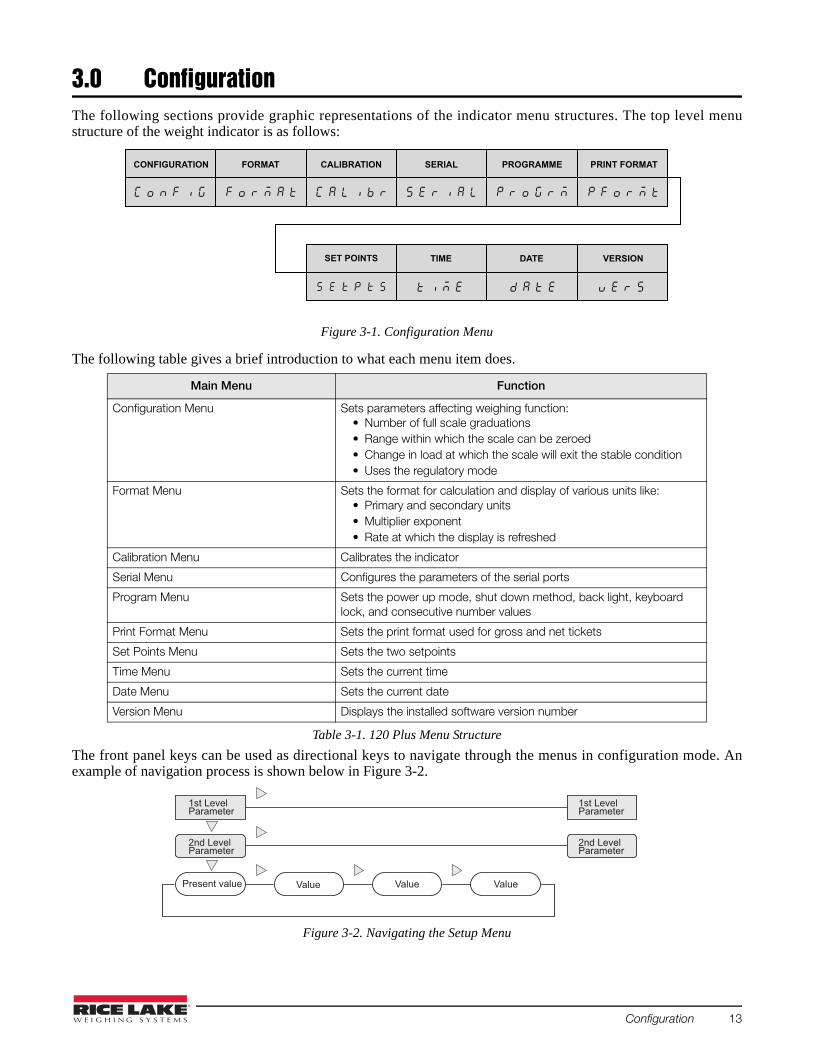
3.0 ConfigurationThe following sections provide graphic representations of the indicator menu structures. The top level menustructure of the weight indicator is as follows:
Figure 3-1. Configuration Menu
The following table gives a brief introduction to what each menu item does.
The front panel keys can be used as directional keys to navigate through the menus in configuration mode. Anexample of navigation process is shown below in Figure 3-2.
Figure 3-2. Navigating the Setup Menu
Main Menu Function
Configuration Menu Sets parameters affecting weighing function:• Number of full scale graduations• Range within which the scale can be zeroed• Change in load at which the scale will exit the stable condition• Uses the regulatory mode
Format Menu Sets the format for calculation and display of various units like:• Primary and secondary units• Multiplier exponent• Rate at which the display is refreshed
Calibration Menu Calibrates the indicator
Serial Menu Configures the parameters of the serial ports
Program Menu Sets the power up mode, shut down method, back light, keyboard lock, and consecutive number values
Print Format Menu Sets the print format used for gross and net tickets
Set Points Menu Sets the two setpoints
Time Menu Sets the current time
Date Menu Sets the current date
Version Menu Displays the installed software version number
Table 3-1. 120 Plus Menu Structure
CONFIGURATION FORMAT CALIBRATION SERIAL PROGRAMME PRINT FORMAT
TIME DATE VERSIONSET POINTS
1st LevelParameter
2nd LevelParameter
1st LevelParameter
2nd LevelParameter
Present value ValueValueValue
Configuration 13

3.1 Configuration MenuUse this mode to configure the parameters of the weighing scale. To configure items from this menu, press thesetup switch. the configuration menu is shown below.
Figure 3-3. Configuration Menu
CONFIGURATION
1
2
4
8
16
32
64
128
DIGITAL FILTERING1
1
2
4
8
16
1
2
4
8
16
2OUT
4OUT
8OUT
16OUT
32OUT
64OUT
128OUT
NONE
2DD
5DD
10DD
20DD 100 %
DIGITAL FILTERING2
DIGITAL FILTERING3
DIGITAL FILTERSENSING
DIGITAL FILTER THRESHOLD
INITIAL ZERORANGE
OFF
8 %
20 %
50 %
32
64
128
32
64
128
2500
number
Off
0.5D
1D
3D
1.9%
100%
1D
2D
3D
5D
10D
20D
50D
OFF
FS+2%
FS+1D
FS+9D
FS
GRADUATIONS ZERO TRACKING BAND ZERO RANGE MOTION BAND OVERLOAD
REGULATORYMODE
NTEP
OMIL
CANADA
NONE
100DD
200DD
50DD
250DD
14 120Plus Digital Weight Indicator Technical Manual

The following table describes the various configuration options (values in bold are the default values).
Parameter Options Description
Graduations 10000Number
The value entered must be in the range 1 ~ 100000 and should be consistent with legal requirements and environmental limits on system resolution. To calculate GRADS, use the formula: Grads = Capacity / Min. Weight Min. Weight for primary and secondary units are specified on the FORMAT menu.
Zero tracking band
OFF0.5D1D3D
This automatically zeros the scale when the input drifts slowly within the specified range and speed as defined by the parameter which covers the upper and lower limits. The maximum legal value is dependent on local regulations.
Zero range 1.9%100%
This is the range within which the scale can be zeroed. For example, if this value is set to 1.9%, it means that the zero range is ±1.9% around the calibrated zero point, for a total range of 3.8%. The indicator must be in a stable condition to zero the scale. Use 1.9% for legal-for-trade applications. 100% indicates the scale can be zeroed at any load.
Motion band 1D2D3D5D10D20D50DOFF
Defines the change in load at which the scale will exit a stable condition (motion condition). If motion is not detected for more than 1 second, the stability annunciator lights. The motion band value must satisfy local regulations.
Overload FS+2%FS+1DFS+9DFS(FS=full scale)
Defines the point of overload or underload. The display indicates "------” when the point of overload is reached. The maximum or minimum legal value varies depending on legal regulations.
Digital filter 1/2/3
2148163264128
Defines the digital filtering rate used to reduce the effects of mechanical vibration. Choices indicate the number of A/D conversions that are averaged to obtain the displayed reading. A higher number gives a more stable display by minimizing the effect of a few noisy readings, but slows down the setting rate of the indicator.
Digital filter cutout sensitivity
8out2out4out16out32out64out128out
Defines the number of consecutive readings that must fall outside the filter threshold (defined by DFTHRH) before digital filtering is suspended.
Digital filter cutout threshold
None2DD5DD10DD20DD50DD100DD200DD250DD
Specifies the filter threshold in display divisions. When a specified number of consecutive scale readings (DFSENS parameter) fall outside this threshold, digital filtering is suspended. If NONE is selected, the filter is always enabled.
Initial zero range OFF8%20%50%100%
Defines the range within which the scale can be zeroed while power is on. Each range is a plus or minus value. For example, 8% means ± 8% around the calibrated zero point, for a total range of 16%.
Table 3-2. Configuration Menu
Configuration 15

3.2 Format MenuThe items in this menu are used to configure the format for calculation and display of various units. To configureitems from this menu, enter configuration mode and then press the right arrow key once.
The Format menu is shown below:
Figure 3-4. Format Menu
Regulatory mode
NTEPOIMLCanadaNone
Specifies the regulatory agency having jurisdiction over the scale site.
Parameter Options Description
Table 3-2. Configuration Menu
FORMAT
PRIMARY
888888
88.8888
888.888
8888.88
DECIMAL POINT
8.88888
88888.8
DISPLAY DIVISIONS UNITS
SECONDARY
DECIMAL POINT
888888
88.8888
888.888
8888.88
8.88888
88888.8
DISPLAYDIVISIONS UNITS
HIRES
OFF
ON
DISPLAY RATE
250MS
500MS
1SEC
2SEC
1D
2D
5D
10D
20D
50D
100D
200D
500D
LB
G
OZ
T
1D
2D
5D
10D
20D
50D
100D
200D
500D
KG
G
OZ
T
KG LB
16 120Plus Digital Weight Indicator Technical Manual

Parameter Options Description
Primary DECPNTDSPDIVUNIT
Specifies the Primary decimal position, display divisions, and units used for the primary units.
Decimal point 8888888.8888888.8888888.8888888.8888888.8
Decimal Point defines the location of the decimal point or dummy zero for the primary unit display. The value set should be consistent with local legal requirements.
Display divisions 1D2D5D10D20D50D
Display Division defines the minimum division size for the weight displayed by the primary units.
Units LB (pound)KG (kilogram)OZ (ounce)G (gram)T (ton)
This defines the primary Units for display and printing.
Secondary DECPNTDSPDIVUNIT
Specifies the Secondary decimal position, display divisions, and units used for the secondary units.
Decimal point 88888.88888888.8888888.8888888.8888888.88
Decimal Point Location defines the location of the decimal point or dummy zero for the primary unit display. The value set should be consistent with local legal requirements.
Display divisions 5D1D2D10D20D50D
Display Divisions defines the minimum division size for the weight displayed by the secondary units.
Units KG (kilogram)G (gram)OZ (ounce)T (ton)LB (pound)
This defines the secondary Units for display and printing.
Display rates 250 MS500 MS1 Sec2 Sec
Display Rate - sets the update rate for displayed values.
Hires OFF ON
Hires - sets ON the instrument to display weight at 10 times resolution. This is intended for test purposes but may be used for non-trade weighing. Note: Do not set this parameter to ON if PRI. DECPNT = 8.88888 or SEC. DECPNT = 8.88888. On high resolution mode the display blinks.
Table 3-3. Format Menu
Configuration 17

3.3 Calibration3.3.1 Calibration MenuThis menu is used to calibrate the indicator. To configure items from this menu, enter configuration mode and thenpress the right arrow key twice.
CAL indicates that the machine is calibrating the selected value. The Calibration menu is shown below:
Figure 3-5. Calibration Menu
The following table describes the various calibration options (values in bold are default values).
3.3.2 Front Panel CalibrationTo calibrate the indicator using the front panel, do the following:
1. Place the indicator in configuration mode by pressing the setup switch in the back (See figure 1-3). Thedisplay reads CONFIG. Remove all weight from the scale platform. If your test weights require hooks orchains, place the hooks or chains on the scale for zero calibration.
2. Press the 6 key until the display reads CALIBR. Press the 8 key to navigate to zero calibration (WZERO).
3. With WZERO displayed, press the enter key to calibrate zero. The indicator displays CAL while calibrationis in progress. When complete, WVAL is displayed.
4. With WVAL displayed, place test weights on the scale and press the 8 key to show the test weight value.Press the enter key again; the last digit of the displayed value blinks. Press the clear key to clear the value,then use the numeric keys (0-9) to enter the test weight value. Press the enter key to save the test weightvalue and navigate to span calibration (WSPAN).
5. With WSPAN displayed, press the enter key to calibrate span. The indicator displays CAL while calibration
Parameter Options Description
Weight Zero None Displays zero calibration weight value. Do not adjust this value after WSPAN has been set.
Weight Value 250 Test_weight
Displays and edits the test weight value.
Weight Span None Displays span calibration weight value.
Rezero None Removes an offset value from the zero and span calibrations. Use this setting only after WZERO and WSPAN have been set.
Latitude 45 The latitude in degrees at the place of calibration
Elevation 345 The elevation in meters at the place of calibration
Table 3-4. Calibration Menu
CALIBRATION
WEIGHT ZERO WEIGHT VALUE WEIGHT SPAN
10000
REZERO
Press Enter to removeoffset from zero and
span calibration
Press Enter to acquirespan calibration A/D
count value
Press Enter to acquirezero calibration A/D
count value
LATITUDE ELEVATION
45 345
L A T I T D E L E U T N
18 120Plus Digital Weight Indicator Technical Manual

is in progress. When complete, REZERO is displayed.
6. Optional: The rezero function is used to remove a calibration offset when hooks or chains are used to hangthe test weights.
• If hooks or chains were used during calibration, remove these and all test weights from the scale. Pressthe enter key to rezero the scale. This function adjusts the zero and span calibration values. Whencomplete, CAL is displayed.
7. Press the 2 key until the display reads EXIT Y, then press enter key to exit configuration mode.
When editing numeric values, press the enter key to allow the numeric entry, and then press the clear key toclear the values. Press numeric keys (0~9) to enter the value. Press the enter key to save the value entered andreturn to the level above.
The calibration process is depicted in the following figure:
Figure 3-6. Calibration Process
NOTE 1: Place test weights.
NOTE 2: Use arrow keys, see Figure 3-2 on page 13 to set the maximum weight value.
NOTE 3: Optional - use only when hooks or chains were used during calibration. To recalibrate zero, remove theseand the test weights from the scale.
3.3.3 EDP Command CalibrationTo calibrate the indicator using EDP commands, the indicator EDP port must be connected to a terminal orpersonal computer. See Section 2.2 on page 7 for EDP port pin assignments; see “Appendix A Electronic DataProcessing Commands EDP” for more information about using EDP commands. Once the indicator is connected tothe sending device, do the following:
1. Place the indicator in configuration mode (the display reads CONFIG) and remove all weight from the scaleplatform. If your test weights require hooks or chains, place the hooks or chains on the scale for zerocalibration.
2. Send the WZERO command to calibrate zero. The indicator displays *CAL* while calibration is in progress.NOTE: During EDP command calibration, the *CAL* message remains on the display. Once the calibrationis complete, the OK message appears on the display.
3. Place test weights on the scale and use the WVAL command to enter the test weight value in the followingformat: WVAL=nnnnnn<CR>.
4. Send the WSPAN command to calibrate span. The indicator displays *CAL* while calibration is in progress.
5. To remove an offset value, clear all weight from the scale, including hooks or chains used to hang testweights, and then send the REZERO command. The indicator displays *CAL* while the zero and spancalibrations are adjusted.
Note
CONFIGURATION FORMAT CALIBRATION
Note 3
OR
REZEROWEIGHT SPANWEIGHT VALUEWEIGHT ZERO
CALIBRATION
Note 2
######
Test Weight Value
Note 1
l h
LATITUDE ELEVATION
L A T I T D E L E V T N
Configuration 19

3.4 Serial MenuThe items in this menu are used to configure the serial port used for transferring data between the indicator and aPC or printer. To configure items in this menu, press the setup switch and then the right arrow key three times.
The Serial menu is shown below:
Figure 3-7. Serial Menu
Parameter Options Description
Electronic Data Processing (EDP)
BaudBitsTermEchoAddres
Specifies port settings for baud rate, data bits, termination characters, and end- of-line delay used by the EDP port.
Baud 96001200240048001920038400
Baud Rate. Selects the transmission speed for the EDP port.
Bits 8NONE 7ODD7EVEN 7SPACE
Selects number of data bits and parity of data transmitted from the EDP port.
Termination CR/LF CR
Selects the termination character for data sent from the EDP port.
Echo ON OFF
Specifies whether commands sent to the indicator are echoed.
Table 3-5. Serial Menu
CR
CR/LF
TERMINATION
SERIAL
1200
BAUD
38400
4800
19200
9600
2400
BITS
8NONE
70DD
7EVEN
7SPACE
TERMINATION
CR
CR/LF
ECHO
ON
OFF
1200
9600
4800
2400
BAUD
8NONE
70DD
7EVEN
7SPACE
BITS
GERMAN
ENGLIS
LANGUAGE
ELECTRONIC DATA PROCESSING
STREAM
OFF
EDP
PRN
STREAM DELAY
250MS
2SEC
1SEC
8SEC
4SEC
500MS
15SEC
ADDRESS
00
number
PROTECT
Enable
DisableEDP
PRN
MONBAT
ON
OFF
CINSTR
ON
OFF
DATA TRANSMISSIONPORT
19200
NONE
20 120Plus Digital Weight Indicator Technical Manual

Address 00 number
Specifies the node address of RS485. The value is in hex format. 00 represents that this function is disabled.If ADDRESS is enabled, EDP commands became <ADDRESS> + command, where address is one byte, and auto off echo even if echo is on.Note: User can connect via an external RS232 to RS485 converter.
Print BAUD BITSTERMLANGUAGE
Specifies port settings for baud rate, data bits, termination characters, and end- of-line delay used by the printer port.
Baud 9600120024004800
Baud Rate. Selects the transmission speed for the printer port.
Bits 8NONE 7ODD7EVEN 7SPACE
Selects number of data bits and parity of data transmitted from the printer port.
Termination CR/ LF CR
Selects the termination character for data sent from the printer port.
Language ENGLIS GERMAN
Ticket language. Selects the language for the printer tickets.English/ German Gross/ BruttoNet/ Netto Tare/ TaraHeight/ Groesse
Print Destination EDP PRN
Print destination. Selects the port for data transmission when the PRINT key is pressed or the KPRINT EDP command is sent.
Stream OFF EDPPRN
Selects the serial port used for continuous transmission. See " Continuous Output (Stream) Format" on page 46 for more information about the 120 Pluscontinuous data format.
Stream Delay 250MS 500MS1SEC 2SEC4SEC8SEC15SECOFF
Specifies the delay in seconds (SEC) or milliseconds (MS) inserted between stream frames.
Cinstr OFF ON
Selects to enable or disable the stream display for additional raw data and time.
Monbat OFFON
Selects to enable or disable the stream display for additional battery data.
Protect DISABLEENABLE
EDP port protection. Selects ENABLE to secure the EDP port from configuration changes.
Parameter Options Description
Table 3-5. Serial Menu
Configuration 21

3.5 Program MenuUse this menu to configure the power-up mode and consecutive number values of this indicator. The Programmenu is shown below:
Figure 3-8. Program Menu
The following table describes the various program options (values in bold are default values).
Parameter Options Description
Power Up Mode GODELAY
Power up mode. In GO mode, the indicator goes into operation immediately after a brief power up display test.In DELAY mode, the indicator performs the power up display test and enters a 60-second warm up period. Delay mode is terminated either at the end of the warm up period or when the predefined temperature is reached. If motion is not detected during the warm up period, it goes into Normal Mode.
Return to Zero Print Band
10 DIV1D2D3D5D20D50DOff
This sets the number of divisions that the weight must return to around zero before the indicator will allow a print to occur. Set to off to always allow printing.
Shutdown NONE 1MIN2MIN 5MIN10MIN
Remote function for automatic switch off if the instrument in not needed.
LCD Backlight 30SECOFF 15SEC1MIN ON
Function to automatically switch off the LCD back light if the instrument is not in use.
Buzzer OFF ON
Specifies to disable or enable the key tones when pressed.
Table 3-6. Program Menu
LCD BACK LIGHT
NONE
5MIN
2MIN
1MIN
SHUTDOWN
OFF
ON
BUZZER
PROGRAM
POWER UP MODE
GO
DELAY
HOLDMD
2SEC
3SEC
AVERAGE HOLDTM
12SEC
16SEC
14SEC
4SEC
8SEC
6SEC
5SEC
1MIN
2MIN
8MIN
10MIN
3MIN
6MIN
5MIN
4MIN
NONE
UNIT
KEY LOCKOUT
1
number
CONSECUTIVE NUMBERING
10MIN
OFF
1MIN
30SEC
15SEC
ON
DISABL
AUTO
AVERAG
TOGGLE
UNPR
ALL
GRUNPR
PRN
ZOTA
GROSS
HOLD
RETURN TO ZERO PRINT BAND
10 DIV
2 DIV
1 DIV
OFF
3 DIV
20 DIV
5 DIV
50 DIV
r p n b a n
OFF
On
GRAVITY ADJUST
G R A V A D
22 120Plus Digital Weight Indicator Technical Manual

Hold Function TOGGLEDISABL AVERAGAUTO
Hold function.TOGGLE: After pressing the HOLD key the weight will be frozen if no motion and bigger than zero. Press HOLD again, to go back to weighing mode. AVERAG: After pressing the HOLD key if bigger than zero and not increase weight, then start to take the average value in 3 seconds, the average weight will be frozen. Press HOLD again or after 2 minutes, to go back to weighing mode.AUTO: when there is no motion and bigger than zero, the weight will be frozen. Press HOLD again or after 2 minutes, to go back to weighing mode.
Average Timer 4SEC 2SEC 3SEC5SEC6SEC 8SEC12SEC 14SEC16SEC
Timer for hold function to average raw data or time limited according to the HOLDMD setting.See Hold function section for details.
Hold Timer 2MIN1MIN 3MIN 4MIN5MIN 6MIN8MIN 10MIN
Timer for hold function to limit the time of freeze. See Hold function section for details.
Key Lockout NONE UNITPRNHOLDGROSSZOTAUNPR GRUNPR ALL
Front Panel Key Lockout option. In some applications, it is desirable that the front panel keys cannot be accessed while operating in normal mode.NONE: none of the keys are locked. UNIT: UNITS key disabled.PRN: Print/Enter key disabled.HOLD: HOLD key disabled.GROSS: GROSS/NET key disabled.ZOTA: ZERO, TARE, and PRESET TARE keys disabled. UNPR: UNITS and Print/Enter keys disabled.GRUNPR: GROSS/NET, UNITS and Print/Enter keys disabled.ALL: disable all keys. Note that this option only disables the front panel keys and does not lock out the functions that these keys perform. The zero, gross/net, tare, and print command are still accessible from the remote inputs on HDB15 of the 120 Plus.
Consecutive Numbering
1 number
Consecutive Numbering allows sequential numbering for print operations. This value is increased following each print operation.
Gravity Adjust OffOn
Sets the latitude and elevation parameters for the geographic location where the calibration takes place. It compensates for the varience in gravitational pull from one location to another.
Parameter Options Description
Table 3-6. Program Menu
Configuration 23

3.6 Print Format MenuUse these menu options to configure the print format settings. The Print Format menu is shown below:
Figure 3-9. Print Format Menu
The following table describes the various print format options.
Parameter Options Description
EDIT NONE Edits the print format.
INSERT NONE Inserts a new character initialized to 00, at the end of the value edited using the previous EDIT option. This shifts all data after it to the right by one position. After insertion, the user can edit the value.
DELETE NONE Deletes the last character of the value edited by the previous EDIT option. This shifts all data after it to the left by one position.
Table 3-7. Print Format Options
PRINT FORMAT
EDIT
00_@40 00
INSERT DELETE
0 1 N 4 E
Location of the character Blank Visible ASCII Char ASCII in HEX code
24 120Plus Digital Weight Indicator Technical Manual

3.7 Set Points MenuUse this menu to configure set points settings. The Set Points menu is shown below:
Figure 3-10. Set Points Menu
SET POINT 1
KIND CONDIT
N.OPEN
N.CLOSE
CONTACT
10
number
WEIGHT VALVE TIMER HYSTERESISDELAY
NORMAL
STABLE
0%
2%
5%
10%
SET POINTS
OFF
DISPLA
NET
GROSS
NONE
250MS
4.0SEC
5.0SEC
500MS
3.0SEC
1.5SEC
750MS
NONE
250MS
4.0SEC
5.0SEC
500MS
3.0SEC
1.5SEC
750MS
SET POINT 2
KIND CONDIT
N.OPEN
N.CLOSE
CONTACT
20
number
WEIGHT VALVE TIMER HYSTERESISDELAY
NORMAL
STABLE
0%
2%
5%
10%
OFF
DISPLA
NET
GROSS
NONE
250MS
4.0SEC
5.0SEC
500MS
3.0SEC
1.5SEC
750MS
NONE
250MS
4.0SEC
5.0SEC
500MS
3.0SEC
1.5SEC
750MS
REMOTE SWITCH
OF.OF.OF
UN.TA.ZO
PR.TA.ZO
ABSNET
ABSNET
OFF
BUZZER
OFF
BUZZER
ON
ON
Configuration 25

The following table describes the various set points options (values in bold are default values).
Parameter Options Description
Set Point 1 OFFKIND CONTACT CONDITWVAL TIMER DELAYHYSTERBUZZER
Specifies settings for mode, contact type, stability, weight valve, timer, delay, and hysteresis used by the set point 1.
Operation Mode OFF GROSS NETDISPLA
Specifies kinds of Operation mode, comparator source.
Contact Type N.CLOSEN.OPEN
Contact type. Contact status below the set point value, Comparator output to be normal open or normal close.
Stability NORMAL STABLE
Output enabled only after the weight reading has been stabilized.
Weight Value 10 or 20 number
Sets weight thresholds for set point. Output active if load over this weight. (load >= wval)
Timer NONE 250MS500MS750MS1.5SEC 3.0SEC4.0SEC 5.0SEC
Disables output after a specified time.
Delay NONE 250MS500MS 750MS1.5SEC 3.0SEC4.0SEC 5.0SEC
Time delay before the output is enabled.
Hysteresis 0%2%5% 10%
Sets weight thresholds for set point. Output deactive if load under this weight. (load<wval x hysteresis)
Buzzer OFFON
Enable or disable beep from indicator when set point tripped
Set Point 2 OFFKIND CONTACT CONDITWVAL TIMER DELAYHYSTERBUZZER
Specifies settings for mode, contact type, stability, weight valve, timer, delay, and hysteresis used by the set point 2.
Table 3-8. Setpoints Menu
26 120Plus Digital Weight Indicator Technical Manual

3.8 Time MenuUse these menu options to configure time settings. The Time menu is shown below:
Figure 3-11. Time Menu
The following table describes the various time options.
Remote Switch OF.OF.OF PR.TA.ZOUN.TA.ZO{ { {3 2 1
Specifies the function activated by remote switch inputs 1, 2 and 3.OF.OF.OF disable all remote switches PR.TA.ZO provides the same functions as the front panel keys.Remote switch 1 be ZERO keyRemote switch 2 be TARE keyRemote switch 3 be Print/Enter key UN.TA.ZO provides the same functions as the front panel keys.Remote switch 1 be ZERO keyRemote switch 2 be TARE keyRemote switch 3 be UNITS key
Parameter Options Description
Show HH.MM.SS Displays current time in HH.MM.SS format
Hour hour (HH) Sets hour using 24-hour format
Minute minute (MM) Sets minute
Second second (SS) Sets second
Table 3-9. Time Menu
Parameter Options Description
Table 3-8. Setpoints Menu
TIME
SHOW
00.00.00
Displaytime
00
HOUR
00-23
MINUTE
00
00-59
SECOND
00
00-59
Configuration 27

3.9 Date MenuUse these menu options to configure date settings. The Date menu is shown below:
Figure 3-12. Date Menu
The following table describes the various date options.
3.10 Version MenuThis shows the software version of this indicator. The Version menu is shown below.
Figure 3-13. Version Menu
Parameter Options Description
SHOW MM.DD.YY Displays current date in YY.MM.DD, DD.MM.YY or MM.DD.YY format
YEAR year (YY) Set year (two digits 00-99)
MONTH month (MM) Set month (MM)
DAY day (DD) day (DD)
DATFRM MMDDYYDDMMYYYYMMDD
Specifies the date format. MMDDYY: month, day, yearDDMMYY: day, month, yearYYMMDD: year, month, day
Table 3-10. Date Menu
DATE
SHOW
03.01.01 03
YEAR
Displaydate 00-99
01
01-12
MONTH
01
01-31
DAY
YYMMDD
DDMMYY
DATFRM
MMDDYY
VERS
SoftwareVersion
28 120Plus Digital Weight Indicator Technical Manual

4.0 Test Mode OperationsUse this mode to test the parameters of the weight indicator.
This procedure should only be performed by a certified technician.
To enter test mode, press the “setup switch” for three seconds. The display will change from CONFIG to A/DTST.
Figure 4-1. Test Mode Operation Menu
Parameter Description
A/D TEST Displays A/D Test. Press the ENTER key to display the raw count value from A/D converter.
TEST LCD Light on all LCD segments for test LCD.
I/O Display digital input (Remote Switch) and output (Set Point) status.
BATTERY VOLTAGE
Display battery voltage in V.
BATTER CURRENT
Display battery charging current in A.
FILTER 3 Displays filtered raw count for digital filter 3.
DEFAULT Default parameters. Press the ENTER key to reset configuration and calibration parameters to factory default values.NOTE: Not available in panel mode operation
TRANSMIT U Transmits "U". Press the ENTER key to send the U character [ASCII: 85 decimal, 55 hex] to test the serial line quality and integrity.
Table 4-1. Test Mode Option Parameters
Note
TNERRUC YRETTABEGATLOV YRETTABTSETD/A
uuuuuu READY
DEFAULT TRANSMIT U ECHO R
TEST LCD IO
FEC600
FILTER3
0 0 0 0 0
OUT2
OUT1RSW3RSW2RSW1
Test Mode Operations 29

ECHO R This displays the character received from the serial port to test the serial line quality. Press the down arrow once until the indicator displays "READY". Then, press the ENTER key on the front panel. This displays the value received from serial port on the front panel. The format of the data displayed by the ECHO R command is shown as shown:
Parameter Description
Table 4-1. Test Mode Option Parameters
0 1 N 4 E
Received character order Blank Visible ASCII Char ASCII in HEX code
30 120Plus Digital Weight Indicator Technical Manual

5.0 Panel Mode OperationsPanel Mode provides access to setting the serial port, non-meteorological parameters, time, date, consecutivenumber, print format, set points, and test items without the need to press the “Setup Switch.”
To enter Panel Mode, press and hold the CLEAR key under normal mode until the FILTER menu is displayed. Use thenavigation keys to move around the menu; to change a value, use the navigation keys to select the digit andincrease or decrease its value. Press the ENTER key to set the value and return to the menu level above. Thepictorial representation of the panel menu is as follows:
Figure 5-1. Panel Mode Operation Menu
1
2
4
8
16
32
64
128
DIGITAL FILTERING1
1
2
4
8
16
1
2
4
8
16
2OUT
4OUT
8OUT
16OUT
32OUT
64OUT
128OUT
DIGITAL FILTERING2
DIGITAL FILTERING3
DIGITAL FILTERSENSING
32
64
128
32
64
128
NONE
2DD
5DD
10DD
20DD
DIGITAL FILTER THRESHOLD
100DD
200DD
250DD
FILTER SERIAL PROGRAMME PRINT FORMT SET POINTS
See Section
3.4
See Section
3.1
See Section
3.5
See Section
3.6
See Section
3.7
TEST VERSION
See Chapter 4
See Section
3.8
See Section
3.9
See Section
3.10
TIME DATE
DISPLAY RATE
250MS
500MS
1SEC
2SEC
Panel Mode Operations 31
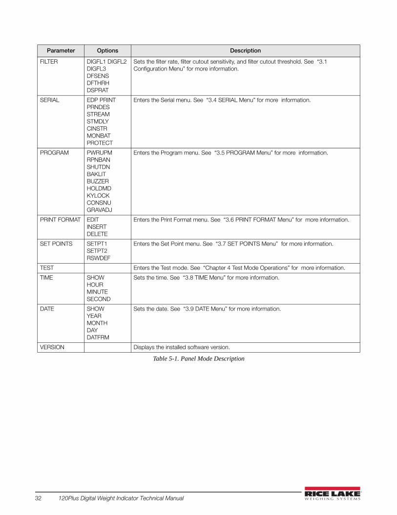
Parameter Options Description
FILTER DIGFL1 DIGFL2DIGFL3 DFSENS DFTHRHDSPRAT
Sets the filter rate, filter cutout sensitivity, and filter cutout threshold. See “3.1 Configuration Menu” for more information.
SERIAL EDP PRINTPRNDES STREAMSTMDLY CINSTRMONBAT PROTECT
Enters the Serial menu. See “3.4 SERIAL Menu” for more information.
PROGRAM PWRUPMRPNBAN SHUTDNBAKLIT BUZZER HOLDMD KYLOCKCONSNUGRAVADJ
Enters the Program menu. See “3.5 PROGRAM Menu” for more information.
PRINT FORMAT EDITINSERT DELETE
Enters the Print Format menu. See “3.6 PRINT FORMAT Menu” for more information.
SET POINTS SETPT1 SETPT2RSWDEF
Enters the Set Point menu. See “3.7 SET POINTS Menu” for more information.
TEST Enters the Test mode. See “Chapter 4 Test Mode Operations” for more information.
TIME SHOW HOURMINUTE SECOND
Sets the time. See “3.8 TIME Menu” for more information.
DATE SHOW YEARMONTH DAYDATFRM
Sets the date. See “3.9 DATE Menu” for more information.
VERSION Displays the installed software version.
Table 5-1. Panel Mode Description
32 120Plus Digital Weight Indicator Technical Manual

6.0 Print Formatting
6.1 Print Format CommandsThe following table gives the possible indicator parameters and command values that may be printed.
This section describes setting the print formats for the indicator, using the serial port or the front panel. There aretwo methods to edit the print format.
6.2 Using Any Editor Through EDPWrite the print format data in pure text format. The following samples are for an Eltron LP 2742 printer.
Wwpf = 0 N A0,0,0,3,1,2,N,"Vishay Transducers Ltd. @d @t @C" A8,50,0,5,1,1,N,"@G" @MA8,120,0,5,1,1,N,"@T" A8,190,0,5,1,1,N,"@N"@M B8,260,0,3,3,7,100,B,"@G" P1
First, place a "WWPF=0" in the first line to indicate that the following is a print format file. Place printerparameters in the beginning of each line as required, and then use double quotes to contain the text that you wantto print on the ticket (see table above).
Note in the above example, N, AxxxxN, B, and P1 are printer specific parameters for the Eltron LP 2742. ASCIIcharacters in HEX mode:
wpf=0 4E 0D 41 30 2C 30 2C 30 2C 33 2C 31 2C 32 2C 4E 2C 22 43 65 6C 74 72 6F 6E 20 54 65 63 68 6E 6F 6C 6F 67 69 65 73 20 49 6E 63 2E 20 40 64 20 40 74 20 40 43 22 0D 41 38 2C 35 30 2C 30 2C 35 2C 31 2C 31 2C 4E 2C 22 40 47 22 0D 40 4D 41 38 2C 31 32 30 2C 30 2C 35 2C 31 2C 31 2C 4E 2C 22 40 54 22 0D 41 38 2C 31 39 30 2C 30 2C 35 2C 31 2C 31 2C 4E 2C 22 40 4E 22 40 4D 0D 42 38 2C 32 36 30 2C 30 2C 33 2C 33 2C 37 2C 31 30 30 2C 42 2C 22 40 47 22 0D 50 31 0D
First, place "WPF=0" in the first line to indicate that the following is a print format file. Then place each characterin ASCII HEX format and include a 0D for carriage return.
Command Description
@G Gross weight in displayed units. This also displays the weight units used.
@T Tare weight in displayed units.
@N Net weight in displayed units.
@C Print consecutive number.
@Ln New line, n specifies termination number.
@t Time
@d Date
@Sn Space, n specifies the number of spaces.
@M Use in pairs to quote Tare and Net data. If Tare is present, then the Tare and Net data will be printed on the ticket.
identifier. The total field length with units identifier is 12 (or 13) characters. ID and consecutive number (CN) fields are 1-6 characters in length, as required.Gross, Net and Tare weights are 9 digits in length, including sign (10 digits with decimal point), followed by a space and a two-digit units
Table 6-1. Print Format Commands
Print Formatting 33

6.3 Using Front Panel EditingUsing the PFORMT menu (see Figure 3-8), you can edit the print format string by changing the hex values of theASCII characters in the format string.
To edit a print format, do the following:
1. In configuration mode, use the navigation keys to go to the PFORMAT menu. Press the 8 key to show theEDIT submenu.
2. Press the 8 key again to show the print format string. Use the 4 key and the 6 key to scroll through theformat. The number position of each character is shown in the two digits at the left of the display.
To Edit a Character:1. Press the ENTER key while the character is displayed. The right most digit blinks, indicating that it can be
changed. Use the 2 key and 8 keys to increase or decrease the value, or use the 4 key to move to the nextdigit. Press the ENTER key to save any changes and advance to the next character in the string.
2. If done, press the 2 key to return to the EDIT submenu.
To Insert One of More Characters:1. Move the cursor to the character after which new characters are to be inserted.2. Press the 2 key to return to the EDIT submenu, and then press the 6 key to show the INSERT parameter.
3. Press the ENTER key to insert one character; press repeatedly to add more characters. Each press of theENTER key adds a character at the location last shown under EDIT submenu and shifts all subsequentcharacters to the right. Inserted characters are assigned hex value 00 (null). To edit inserted characters,return to the EDIT submenu and make changes as described in this section “To edit a character.”
To Delete One of More Characters1. Move the cursor to the character to be deleted.2. Press the 2 key to return to the EDIT submenu, and then press the 6 key twice to show the DELETE
parameter.
3. Press ENTER key to delete one character; press repeatedly to delete more characters. Each press of theENTER key deletes a character, starting at the location last shown under EDIT submenu, and then movingleft to preceding characters. Each deletion shifts all subsequent characters to the left.
The format of the characters to be entered is shown.
Figure 6-1. Print Format
• EDP or Electronic Data Processing refers to a PC or a terminal that can enter ASCII characters using a keyboard and ascreen via the EDP interface of the 120 Plus.
• Some characters cannot be displayed on the 120 Plus front panel (See the ASCII character chart in Appendix C - ASCIISet and Specifications and Appendix E - Front Panel Display Characters on pages 44 and 48.) and are shown as blanks.The 120 Plus can send or receive any ASCII character; the character printed depends on the particular ASCII characterset implemented for the receiving device.
0 1 N 4 E
Location of the character Blank Visible ASCII Char ASCII in HEX code
Note
34 120Plus Digital Weight Indicator Technical Manual

Setpoint Operation 35
7.0 Setpoint Operation
Figure 7-1. Setpoint Operation
The following steps describe the internal steps of setpoint operation. To configure setpoints, refer to Section 3.7 onpage 25.
1. Power on the Toggle Flip-Flop Q=1, The CPU output may be high or low depending on the Sn.CONTACTselection. Also, the XRL gate becomes an inverter.
2. If load (may be gross, net, or display parameters depending on the KIND command) is bigger thanSn.WAVL, the output of XRL gate is high, otherwise it is low.
3. The timer will begin counting if the load is greater than Sn.WVAL. If not, the timer will load from SW2.
4. The Output of AND gate will be high if the output of OR gate is high. (Depends on Sn.CONDITIselection.) Otherwise, wait until standstill is high (If Sn.CONDITI = STABLE).
5. Output (Q) of the Toggle F-F changed from 1 to 0 and the COIL also changed state. (NO to NC, or NC toNO.) And SW1 & SW2 switch over other side, respective changed Comparator BASE and Timer constant.
Comparetor Time r
Q
Toggle F-F
AND
OR
Standstill
Sn.CONDITI
NORMAL
STABLE
1
0
Sn.CONTACT
-
+
Sn.W
VA
L
Sn.W
VA
L x
(1-S
x.H
yste
r)
1
Sn.T
IME
R
Sn.D
ELA
Y
1
Gross
NET
KIND
R
+5V
N.O
N.C
Consant Load
COIL 0V
120 Plus
CPU
XRL
Po
wer O
n
SET
0 0
SW1 SW2
Display

8.0 Appendix
8.1 Appendix A Electronic Data Processing Commands EDPThe EDP port and commands may be used to set indicator parameters, retrieve indicator parameters, and set printformats.
To set parameter values, enter the corresponding EDP commands from the terminal. In order to set the parametervalues, use the following format:
“Command=Parameter Value" For example: To set GRADS (graduations) to 5000, do the following:
grads=5000 (Press "Enter" on the keyboard)
OK
OK: Indicates the setting was valid.
To retrieve parameter values, send the parameter name. For example: To retrieve the GRADS (graduations) value,do the following:
grads (Press "Enter" on the keyboard)
5000
The value of GRADS is returned as 5000.
If an unknown command is sent, or a known command is sent, but an attempt is made to set it to an incorrect value,the indicator will respond with double question marks (??).
8.1.1 General Commands
Command Function
DUMPALL List all parameter values
VERSION Show 120 Plus software version "120 Plus X.xx"
P Show currently displayed weight with single letter unit (L for pounds, K for kilograms)
ZZ Return current displayed weight with unit Format: swwwwwww uu zzzs: positive " ", negative "-" wwwwwww: currently displayed weight value - - - - - - - (overload), :::::: (underrange)uu: currently displayed unitzzz: annunciator status value
1: lb on Annunciator 2: kg on Annunciator4: oz on Annunciator 8: g on Annunciator16: Hold on Annunciator 32: Net on Annunciator64: Center of zero on Annunciator 128: Standstill on AnnunciatorFor example, if the annunciator status value returned with the ZZ command is 145, thegross, standstill, and lb annunciators are lit: 145 represents the sum of the values for thestandstill annunciator, gross mode annunciator, and the lb/primary units annunciator.
BAT Battery voltage and charging current
ADS A/D converter memory map
IO List status of digital input (Remote Switch) and output (Set Point)
Table 8-1. General Commands
0 0 0 0 0
OUT2
OUT1RSW3RSW2RSW1
36 120Plus Digital Weight Indicator Technical Manual

8.1.2 Configuration Commands
8.1.3 Format Commands
8.1.4 Calibration Commands
Command Description Values
GRADS Graduations 1 - 10000
ZTRKBND Zero Track Band OFF, 0.5D, 1D, and 3D
ZRANGE Zero Range 1.9%, 100%
MOTBAND Motion Band OFF, 1D, 3D, 5D, 10D, 20D, and 50D
OVRLOAD Overload FS+2%, FS+1D, FS+9D, and FS
DIGFLTR 1DIGFLTR 2DIGFLTR 3
Digital Filtering 1-3 1, 2, 4, 8, 16, 32, 64, and 128
DFSENS Digital Filtering Cutout Sensitivity
2out, 4out, 8out, 16out, 32out, 64out, and 128out
DFTHRH Digital Filtering Cutout Threshold
NONE, 1DD, 2DD, 5DD, 10DD, 20DD, 50DD, 100DD, 200DD, and 250DD
INIZR Initial Zero Range 8%, 20%, 50%, 100%, OFF
REGULAT Regulatory Compliance NTEP, OIML, CANADA, NONE
Table 8-2. Configuration Commands
Command Description Values
PRI.DECPNT primary units decimal point position 8.88888, 88.8888, 888.888, 8888.88, 88888.8, and 888888
PRI.DSPDIV Primary units display division 1D, 2D, 5D, 10D, 20D, 50D, 100D, 200D, and 500D
PRI.UNITS Primary units LB, KG, OZ, G
SEC.DECPNT Secondary units decimal points position 8.88888, 88.8888, 888.888, 8888.88, 88888.8, and 888888
SEC.DSPDIV Secondary units display division 1D, 2D, 5D, 10D, 20D, 50D, 100D, 200D, and 500D
SEC.UNITS Secondary units LB, KG, OZ, G
DSPRAT Display rate 250 ms, 500 ms, 1 sec, 2 sec
HIRES Hires ON, OFF
Table 8-3. Format Commands
Command Description Values
WZERO Zero calibration -
WVAL Test weight value test_weight_value
WSPAN Span calibration -
REZERO Rezero -
LC.CD Set deadload coefficient value
LC.CW Set span coefficient value
LAT.CAL Latitude at calibration -
ELEV.CAL Elevation at calibration -
Table 8-4. Calibration Commands
Appendix 37
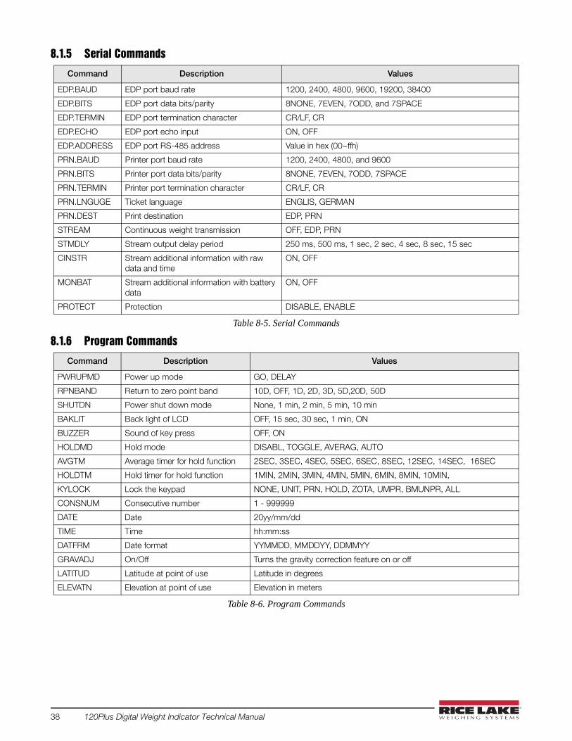
8.1.5 Serial Commands
8.1.6 Program Commands
Command Description Values
EDP.BAUD EDP port baud rate 1200, 2400, 4800, 9600, 19200, 38400
EDP.BITS EDP port data bits/parity 8NONE, 7EVEN, 7ODD, and 7SPACE
EDP.TERMIN EDP port termination character CR/LF, CR
EDP.ECHO EDP port echo input ON, OFF
EDP.ADDRESS EDP port RS-485 address Value in hex (00~ffh)
PRN.BAUD Printer port baud rate 1200, 2400, 4800, and 9600
PRN.BITS Printer port data bits/parity 8NONE, 7EVEN, 7ODD, 7SPACE
PRN.TERMIN Printer port termination character CR/LF, CR
PRN.LNGUGE Ticket language ENGLIS, GERMAN
PRN.DEST Print destination EDP, PRN
STREAM Continuous weight transmission OFF, EDP, PRN
STMDLY Stream output delay period 250 ms, 500 ms, 1 sec, 2 sec, 4 sec, 8 sec, 15 sec
CINSTR Stream additional information with raw data and time
ON, OFF
MONBAT Stream additional information with battery data
ON, OFF
PROTECT Protection DISABLE, ENABLE
Table 8-5. Serial Commands
Command Description Values
PWRUPMD Power up mode GO, DELAY
RPNBAND Return to zero point band 10D, OFF, 1D, 2D, 3D, 5D,20D, 50D
SHUTDN Power shut down mode None, 1 min, 2 min, 5 min, 10 min
BAKLIT Back light of LCD OFF, 15 sec, 30 sec, 1 min, ON
BUZZER Sound of key press OFF, ON
HOLDMD Hold mode DISABL, TOGGLE, AVERAG, AUTO
AVGTM Average timer for hold function 2SEC, 3SEC, 4SEC, 5SEC, 6SEC, 8SEC, 12SEC, 14SEC, 16SEC
HOLDTM Hold timer for hold function 1MIN, 2MIN, 3MIN, 4MIN, 5MIN, 6MIN, 8MIN, 10MIN,
KYLOCK Lock the keypad NONE, UNIT, PRN, HOLD, ZOTA, UMPR, BMUNPR, ALL
CONSNUM Consecutive number 1 - 999999
DATE Date 20yy/mm/dd
TIME Time hh:mm:ss
DATFRM Date format YYMMDD, MMDDYY, DDMMYY
GRAVADJ On/Off Turns the gravity correction feature on or off
LATITUD Latitude at point of use Latitude in degrees
ELEVATN Elevation at point of use Elevation in meters
Table 8-6. Program Commands
38 120Plus Digital Weight Indicator Technical Manual

8.1.7 Print Format Commands
8.1.8 Set Points Commands
Command Description Values
WWPF Print format strings in visible ASCII characters See "Print Formats"
WPF Print format strings in ASCII hex code See "Print Formats"
Table 8-7. PFROMT Commands
Command Description Values
S1.KIND Kinds of Operation mode for set point 1 OFF, GROSS, NET, DISPLA, ABSNET
S1.CONTACT Contact status below the set point 1 value
N.CLOSE, N.OPEN
S1.CONDITI Output enabled only after the weight reading has stabilized
NORMAL, STABLE
S1.WAVL Set weight thresholds for set point 1. Output 1 active if load over this weight (load >= wval)
0 - 999999
S1.HYSTER Set weight thresholds for set point 1. Output 1 deactive if load under this weight (load < wval x hysteresis)
0%, 2%, 5%, and 10%
S1.TIMER Output is disabled after the time period has expired
None, 250ms, 500ms, 750ms, 1.5Sec, 3.0Sec, 4.0Sec, 5.0Sec
S1.DELAY Time delay before the output is enabled None, 250ms, 500ms, 750ms, 1.5Sec, 3.0Sec, 4.0Sec, 5.0Sec
S1.BUZZER Enable/Disable set point OFF, ON
S2.KIND Kinds of Operation mode for set point 2 OFF, GROSS, NET, DISPLA, ABSNET
S2.CONTACT Contact status below the set point 2 value
N.CLOSE, N.OPEN
S2.CONDITI Output enabled only after the weight reading has stabilized
NORMAL, STABLE
S2.WAVL Set weight thresholds for set point 2. Output 2 active if load over this weight (load >= wval)
0 - 999999
S2.HYSTER Set weight thresholds for set point 2. Output 2 deactive if load under this weight. (load < wval x hysteresis)
0%, 2%, 5%, and 10%
S2.TIMER The output is disabled after the time period has expired
None, 250 ms, 500 ms, 750 ms, 1.5 sec, 3.0 sec, 4.0 sec, 5.0 sec
S2.DELAY Time delay before the output is enabled None, 250 ms, 500 ms, 750 ms, 1.5 sec, 3.0 sec, 4.0 sec, 5.0 sec
S2.BUZZER Enable/Disable set point OFF, ON
RSWDEF Specifies the function activated by remote switch inputs 1, 2, and 3.
OF.OF.OF, PR.TA.ZO, UN.TA.ZO
Table 8-8. Set Points Commands
Appendix 39

8.1.9 Other Commands
8.1.10 Key Press on EDP Commands
8.1.11 Tare, Zero key and REGULAT ParameterThe function of the TARE and ZERO keys depends on the value specified for the REGULAT parameter. Table 8-11below describes the function of these keys for each of the regulatory modes.
Command Description Values
DEFAULT Reset default parameter values -
RS Software Reset
IO Report status 4 ports IO and set point I3, I2, I1, O3, O2, O1
Table 8-9. Other Commands
Command Description Values
KZERO Same function as ZERO key press -
KGROSSNET Same function as GROSS/NET key press -
KTARE Same function as TARE key press -
KUNITS Same function as UNITS key press -
KPRIUNIT Force to primary unit -
KSECUNIT Force to secondary unit -
KPRINT Same function as PRINT key press -
KHOLD Same function as HOLD key press
KENTER Same function as ENTER key press
KPTARE Same function as PRESET TARE key press
KCLEAR Same function as CLEAR key press
KNR0-9 Same function as 0-9 key press
Table 8-10. Key Press Commands
REGULAT parameter value Weight on scale Tare in system
Key press function
KTARE KZERO
USA zero or negative no no active zero
yes clear tare
positive no tare
yes tare
CANADA zero or negative no no active zero
yes clear tare
positive no tare
yes no active
EUROPE zero or negative no no active zero
yes clear tare zero and clear tare
positive no tare zero
yes tare zero and clear tare
NONE zero or negative no tare zero
yes clear tare
positive no tare
yes clear tare
Table 8-11. Regular Parameter Values
40 120Plus Digital Weight Indicator Technical Manual
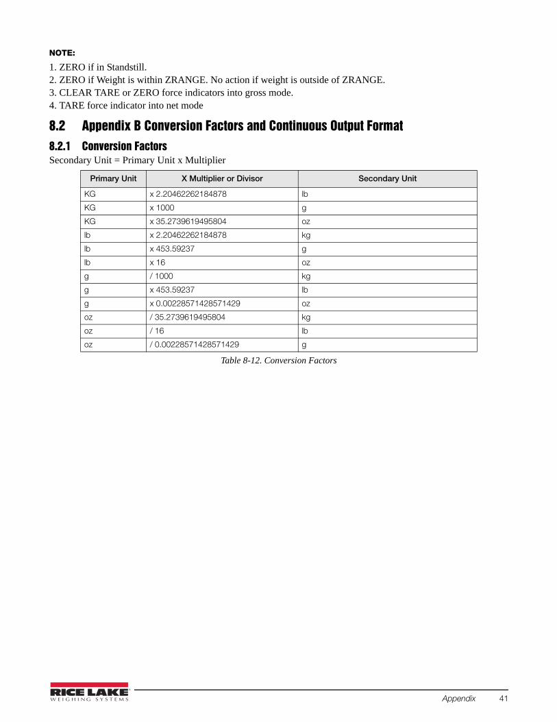
NOTE:
1. ZERO if in Standstill.2. ZERO if Weight is within ZRANGE. No action if weight is outside of ZRANGE.3. CLEAR TARE or ZERO force indicators into gross mode.4. TARE force indicator into net mode
8.2 Appendix B Conversion Factors and Continuous Output Format8.2.1 Conversion FactorsSecondary Unit = Primary Unit x Multiplier
Primary Unit X Multiplier or Divisor Secondary Unit
KG x 2.20462262184878 lb
KG x 1000 g
KG x 35.2739619495804 oz
lb x 2.20462262184878 kg
lb x 453.59237 g
lb x 16 oz
g / 1000 kg
g x 453.59237 lb
g x 0.00228571428571429 oz
oz / 35.2739619495804 kg
oz / 16 lb
oz / 0.00228571428571429 g
Table 8-12. Conversion Factors
Appendix 41

8.3 Appendix C ASCII Set and SpecificationsUse the decimal values for ASCII characters listed in the table, when specifying print format strings on the 120Plus PFORMT menu. The actual character printed depends on the character mapping used by the output device.The 120 Plus can send and receive any ASCII character value (decimal 0-255) but the indicator display is limitedto numbers, upper- case, unaccented letters, and a few special characters.
Table 8-13. ASCII Chart Part 1
Control ASCII Dec Hex ASCII Dec Hex ASCII Dec Hex ASCII Dec Hex
Ctrl-@ NUL 00 00 space 32 20 @ 64 40 ` 96 60
Ctrl-A SOH 01 01 ! 33 21 A 65 41 a 97 61
Ctrl-B STX 02 02 “ 34 22 B 66 42 b 98 62
Ctrl-C ETX 03 03 # 35 23 C 67 43 c 99 63
Ctrl-D EOT 04 04 $ 36 24 D 68 44 d 100 64
Ctrl-E ENQ 05 05 % 37 25 E 69 45 e 101 65
Ctrl-F ACK 06 06 & 38 26 F 70 46 f 102 66
Ctrl-G BEL 07 07 ’ 39 27 G 71 47 g 103 67
Ctrl-H BS 08 08 ( 40 28 H 72 48 h 104 68
Ctrl-I HT 09 09 ) 41 29 I 73 49 i 105 69
Ctrl-J LF 10 0A * 42 2A J 74 4A j 106 6A
Ctrl-K VT 11 0B + 43 2B K 75 4B k 107 6B
Ctrl-L FF 12 0C , 44 2C L 76 4C l 108 6C
Ctrl-M CR 13 0D - 45 2D M 77 4D m 109 6D
Ctrl-N SO 14 0E . 46 2E N 78 4E n 110 6E
Ctrl-O SI 15 0F / 47 2F O 79 4F o 111 6F
Ctrl-P DLE 16 10 0 48 30 P 80 50 p 112 70
Ctrl-Q DC1 17 11 1 49 31 Q 81 51 q 113 71
Ctrl-R DC2 18 12 2 50 32 R 82 52 r 114 72
Ctrl-S DC3 19 13 3 51 33 S 83 53 s 115 73
Ctrl-T DC4 20 14 4 52 34 T 84 54 t 116 74
Ctrl-U NAK 21 15 5 53 35 U 85 55 u 117 75
Ctrl-V SYN 22 16 6 54 36 V 86 56 v 118 76
Ctrl-W ETB 23 17 7 55 37 W 87 57 w 119 77
Ctrl-X CAN 24 18 8 56 38 X 88 58 x 120 78
Ctrl-Y EM 25 19 9 57 39 Y 89 59 y 121 79
Ctrl-Z SUB 26 1A : 58 3A Z 90 5A z 122 7A
Ctrl-[ ESC 27 1B ; 59 3B [ 91 5B { 123 7B
Ctrl-\ FS 28 1C < 60 3C \ 92 5C | 124 7C
Ctrl-] GS 29 1D = 61 3D ] 93 5D } 125 7D
Ctrl-^ RS 30 1E > 62 3E ^ 94 5E ~ 126 7E
Ctrl-_ US 31 1F ? 63 3F _ 95 5F DEL 127 7F
42 120Plus Digital Weight Indicator Technical Manual

Table 8-14. ASCII Chart Part 2
ASCII Dec Hex ASCII Dec Hex ASCII Dec Hex ASCII Dec Hex
Ç 128 80 á 160 A0 192 C0 224 E0
ü 129 81 í 161 A1 193 C1 225 E1
é 130 82 ó 162 A2 194 C2 226 E2
â 131 83 ú 163 A3 195 C3 227 E3
ä 132 84 ñ 164 A4 196 C4 228 E4
à 133 85 Ñ 165 A5 197 C5 229 E5
å 134 86 ª 166 A6 198 C6 230 E6
ç 135 87 º 167 A7 199 C7 231 E7
ê 136 88 ¿ 168 A8 200 C8 232 E8
ë 137 89 169 A9 201 C9 233 E9
è 138 8A ¬ 170 AA 202 CA 234 EA
ï 139 8B 1/2 171 AB 203 CB 235 EB
î 140 8C 1/4 172 AC 204 CC 236 EC
ì 141 8D ¡ 173 AD 205 CD 237 ED
Ä 142 8E « 174 AE 206 CE 238 EE
Å 143 8F » 175 AF 207 CF 239 EF
É 144 90 176 B0 208 D0 240 F0
æ 145 91 177 B1 209 D1 241 F1
Æ 146 92 178 B2 210 D2 242 F2
ô 147 93 179 B3 211 D3 243 F3
ö 148 94 180 B4 212 D4 244 F4
ò 149 95 181 B5 213 D5 245 F5
û 150 96 182 B6 214 D6 246 F6
ù 151 97 183 B7 215 D7 247 F7
ÿ 152 98 184 B8 216 D8 248 F8
Ö 153 99 185 B9 217 D9 249 F9
Ü 154 9A 186 BA 218 DA 250 FA
¢ 155 9B 187 BB 219 DB 251 FB
£ 156 9C 188 BC 220 DC 252 FC
¥ 157 9D 189 BD 221 DD 253 FD
Pts 158 9E 190 BE 222 DE 254 FE
ƒ 159 9F 191 BF 223 DF 255 FF
Appendix 43

8.3.1 Continuous Output (Stream) FormatAll values are ASCII code characters.
Figure 8-1. Continuous Output Format
8.3.2 Extended Format• Extend 1: (If CINSTR = ON)
Figure 8-2. Continuous Output Format
• Extend 2: (If MONBAT = ON)
Figure 8-3. Continuous Output Format
ASCII 02
Weight data: 7 digits, right-justified, with
decimal point, leading zero suppression,
Error= - - - - - -
G= Gross
Extend 1 Fromat:
See below
N= Net
Polarity
L=pounds
K=kilogram
G=grams
O= ounces
Status:
<space>=valid
I= Invalid
M= In motion
H= In Hold
<CR> <LF>
or<CR>
ASCll 13, 10
(Decimal)
<STX> <wwwwww> <UNIT> <G/N> <S> <Extend 1> <TERM>
Extend 2 Fromat:
See below
<Extend 2><Space> <Time>
Time:
<Space> <Date>
8 digits, hh:mm:ss
hh: 00~24
mm: 00~59
ss: 00~59
Date: 10 digits
yyyy/mm/dd if DATFRM= YYMMDD
dd/mm/yyyy if DATFRM= DDMMYY
mm/dd/yyyy if DATFRM= MMDDYY
yyyy: 2000-2009
mm: 01-12
dd:01~31
ASCII 32
(Decimal)
ASCII 32
(Decimal)
<Space><Voltage> <Current>
Battery Voltage
<Space>
8 digits, d.dddddV
ASCII 32
(Decimal)
ASCII 32
(Decimal)
0.00000V~4.50000V
Battery Charging Current
8 digits, d.dddddA
0.00000A~1.00000A
44 120Plus Digital Weight Indicator Technical Manual
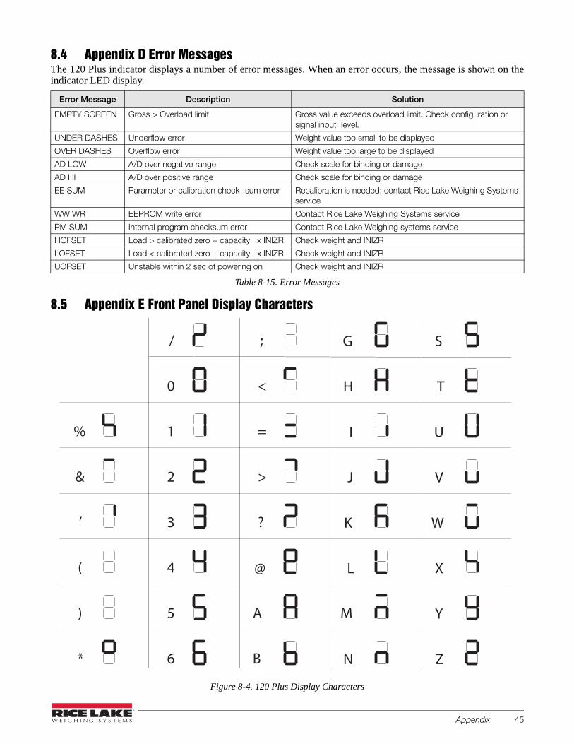
8.4 Appendix D Error MessagesThe 120 Plus indicator displays a number of error messages. When an error occurs, the message is shown on theindicator LED display.
8.5 Appendix E Front Panel Display Characters
Figure 8-4. 120 Plus Display Characters
Error Message Description Solution
EMPTY SCREEN Gross > Overload limit Gross value exceeds overload limit. Check configuration or signal input level.
UNDER DASHES Underflow error Weight value too small to be displayed
OVER DASHES Overflow error Weight value too large to be displayed
AD LOW A/D over negative range Check scale for binding or damage
AD HI A/D over positive range Check scale for binding or damage
EE SUM Parameter or calibration check- sum error Recalibration is needed; contact Rice Lake Weighing Systems service
WW WR EEPROM write error Contact Rice Lake Weighing Systems service
PM SUM Internal program checksum error Contact Rice Lake Weighing systems service
HOFSET Load > calibrated zero + capacity x INIZR Check weight and INIZR
LOFSET Load < calibrated zero + capacity x INIZR Check weight and INIZR
UOFSET Unstable within 2 sec of powering on Check weight and INIZR
Table 8-15. Error Messages
%
&
’
(
)
*
/
0
1
2
3
4
5
6
;
<
=
>
?
@
A
B
G
H
I
J
K
L
M
N
S
T
U
V
W
X
Y
Z
Appendix 45

8.6 Gravity CompensationThis feature is used to compensate for the variance in gravitational pull from one location to another and is
available for the 120+. To calibrate with gravity compensation, the GRAVADJ parameter must be set to ON,
and the LATITUD (latitude in degree) and ELEVATN (elevation in meters, relative to sea level) parameters
set before calibrating the 120+.
If the indicator is later installed at a different location, gravity compensation can be applied to a pre-calibrated
120+ by adjusting the LATITUD and ELEVATN parameters.
Gravity is greater at the poles than at the equator and decreases with increase in altitude. The effect of
gravity at any given location can be calculated using the following formula:-
gCAL = 9.80632 - 0.0258Cos(0.0349065850ØCAL) + 0.00003Cos(0.00698131701Ø) - 0.00000293hCAL (EQ 1)
gOpa = 9.80632 - 0.0258Cos(0.0349065850ØOPA) + 0.00003Cos(0.00698131701Ø) - 0.00000293hOPA (EQ 2)
Where Ø = degrees latitude and h = height in meters
For example:Calibration location at Canada Magog, and Operation location at Taiwan Taipei.The geographic data and calculation:
That means a mass at operation location, ever one kilogram more 1.74 gram. In this way,the same mass will weight in both location is same.
8.7 Summary of ChangesChanges to recent editions of this manual are listed below:
Version 1.07Added information on the following parameters:
• Gravity Adjust - which includes latitude and elevation parameters.• Information has been added in Section 3.3 - Calibration Menu• Information has been added in Section 3.5 - Program Menu• Section 8.6 Section on Gravity Compensation
WOpa =
WCALgOpa
gCAL
if GRAVADJ = ON WOpa = WCAL if GRAVADJ = OFF
WOpa =WCAL
gOpagCAL
Magog: = 45° and h = 222m, Taipei: = 23° and h = 10m
= 9.80564, = 9.78836
9.78836
9.80564
= 1.00174WCAL
Ø Ø
46 120Plus Digital Weight Indicator Technical Manual

8.8 120 Plus SpecificationsPerformanceResolution: 10,000 or 999,999 dd (setup selectable) Conversion Speed: 3, 7, 15, 30 (setup selectable)Sensitivity: 1.0μV/Vsi for approved scales; 0.5μV/Vsi for non-
approved scales. Full Scale Range: 17.5 mV/VLinearity: 0.01% of full scale Excitation: 5 ± 0.3 VDC, 4 x 350 or 8 x 700 load cells (4-
and 6- wires) Offset Drift: 3.5 ppm /ºC Span Drift: 3.5 ppm /ºCA/D Converter Type: Sigma-Delta, ratiometric. Filter: Digital
filter, software selectableCount By: x1, x2, x5, x10, x20, x50, x100, x200, x500 Decimal point setting: between any digits of the weight display Calibration Methods: Software, constants stored in EEPROMWeighing Functions:
Automatic zero trackingNo motion detectionAuto-zero on power-upZeroTareGROSS/NetPrintUnits conversion
Serial CommunicationsEDP Port: Full duplex RS-232
Transmission Rate: 38400, 19200, 9600, 4800, 2400, 1200 bps
Printer Port: Output-only RS-232 or active 20mA current loopTransmission Rate: 9600, 4800, 2400, 1200 bps
EnvironmentalOperating Temperature: -10ºC to +40ºC (14ºF to 104ºF) Storage Temperature: -25ºC to +70ºC (-13ºF to 158ºF)Relative Humidity: 0-95%
Display and KeyboardDisplay: 6 digit, 7-segment, LCD, 21.2 mm Status annunciators: No motion, Center of Zero, Net, units
used (lb, kg, g, oz, t), Battery, Set Points, Hold, HI/ OK/ LO Weight Digits: 4, 5 or 6 (setup selectable)
Keyboard: 18 key flat membrane panel
Power and BatteryVoltage: 5VDC, using power adapter 115 or 230VAC Power
Consumption: 11W in-charger, 2W off-charger
Battery Operation: Charge Time: 7 ~ 10 hoursEstimated Battery Life: Full active: 46 ~ 63 hours Saving: 300 hours
EnclosureBlack ABS Dimensions: 18.6 x 10 x 9.5 cm (7.32" x 4.05" x 3.74") L x H x D Weight: 0.4 kg (without battery)Mounting: Desktop, Wall and Tilt mount
Approvals
OIML - TC7626Accuracy Class III nmax: 10 000
Measurement Canada - Approval: AM 5517 - rev.1Accuracy Class III / III HD nmax: 10 000
NTEP
CoC Number 03-059A1Accuracy Class III / III L nmax: 10 000
NAT
IONAL CONFEREN
CE
ON
WE
IGH T S A N D M E A
SU
RE
S
Appendix 47

120 Plus Limited WarrantyRice Lake Weighing Systems (RLWS) warrants that all RLWS equipment and systems properly installed by aDistributor or Original Equipment Manufacturer (OEM) will operate per written specifications as confirmed by theDistributor/OEM and accepted by RLWS. All systems and components are warranted against defects in materialsand workmanship for one year.
RLWS warrants that the equipment sold hereunder will conform to the current written specifications authorized byRLWS. RLWS warrants the equipment against faulty workmanship and defective materials. If any equipment failsto conform to these warranties, RLWS will, at its option, repair or replace such goods returned within the warrantyperiod subject to the following conditions:
• Upon discovery by Buyer of such nonconformity, RLWS will be given prompt written notice with adetailed explanation of the alleged deficiencies.
• Individual electronic components returned to RLWS for warranty purposes must be packaged to preventelectrostatic discharge (ESD) damage in shipment. Packaging requirements are listed in a publication,Protecting Your Components From Static Damage in Shipment, available from RLWS EquipmentReturn Department.
• Examination of such equipment by RLWS confirms that the nonconformity actually exists, and was notcaused by accident, misuse, neglect, alteration, improper installation, improper repair or impropertesting; RLWS shall be the sole judge of all alleged non-conformities.
• Such equipment has not been modified, altered, or changed by any person other than RLWS or its dulyauthorized repair agents.
• RLWS will have a reasonable time to repair or replace the defective equipment. Buyer is responsible forshipping charges both ways.
• In no event will RLWS be responsible for travel time or on-location repairs, including assembly ordisassembly of equipment, nor will RLWS be liable for the cost of any repairs made by others.
THESE WARRANTIES EXCLUDE ALL OTHER WARRANTIES, EXPRESSED OR IMPLIED, INCLUDING WITHOUTLIMITATION WARRANTIES OF MERCHANTABILITY OR FITNESS FOR A PARTICULAR PURPOSE. NEITHER RLWSNOR DISTRIBUTOR WILL, IN ANY EVENT, BE LIABLE FOR INCIDENTAL OR CONSEQUENTIAL DAMAGES.
RLWS AND BUYER AGREE THAT RLWS’S SOLE AND EXCLUSIVE LIABILITY HEREUNDER IS LIMITED TO REPAIROR REPLACEMENT OF SUCH GOODS. IN ACCEPTING THIS WARRANTY, THE BUYER WAIVES ANY AND ALL OTHERCLAIMS TO WARRANTY.
SHOULD THE SELLER BE OTHER THAN RLWS, THE BUYER AGREES TO LOOK ONLY TO THE SELLER FORWARRANTY CLAIMS.
NO TERMS, CONDITIONS, UNDERSTANDING, OR AGREEMENTS PURPORTING TO MODIFY THE TERMS OF THISWARRANTY SHALL HAVE ANY LEGAL EFFECT UNLESS MADE IN WRITING AND SIGNED BY A CORPORATEOFFICER OF RLWS AND THE BUYER.
© Rice Lake Weighing Systems, Inc. Rice Lake, WI USA. All Rights Reserved.
RICE LAKE WEIGHING SYSTEMS • 230 WEST COLEMAN STREET • RICE LAKE, WISCONSIN 54868 • USA
48 120Plus Digital Weight Indicator Technical Manual

Appendix 49

50 120Plus Digital Weight Indicator Technical Manual


230 W. Coleman St. • Rice Lake, WI 54868 • USA
U.S. 800-472-6703 • Canada/Mexico 800-321-6703 • International 715-234-9171 • Europe +31 (0)26 472 1319
www.ricelake.com www.ricelake.mx www.ricelake.eu www.ricelake.co.in m.ricelake.com
© Rice Lake Weighing Systems 11/17/2014 PN 105914 Rev A
Related Documents