Welcome message from author
This document is posted to help you gain knowledge. Please leave a comment to let me know what you think about it! Share it to your friends and learn new things together.
Transcript
R-90 Series
2
Important Notice Due to the nature of wireless communications, transmission and reception of data can never be guaranteed. Data may be delayed, corrupted (i.e., have errors) or be totally lost. Although significant delays or losses of data are rare when wireless devices such as the router are used in a normal manner with a well-constructed network, the router should not be used in situations where failure to transmit or receive data could result in damage of any kind to the user or any other party, including but not limited to personal injury, death or loss of property. Axesstel accepts no responsibility for damages of any kind resulting from delays or errors in data transmitted or received using the Axesstel router or for failure of the Axesstel router to transmit or receive such data.
Safety Precautions Do not operate the router:
• In areas where blasting is in progress
• Where explosive atmospheres may be present
• Near medical equipment
• Near life support equipment or any equipment that may be susceptible to any form of radio interference. In such areas, the router MUST BE POWERED OFF. The Axesstel router can transmit signals that could interfere with this equipment.
Do not operate the router in any aircraft, whether the aircraft is on the ground or in flight. In aircraft, the router MUST BE POWERED OFF. When operating, the router can transmit signals that could interfere with various onboard systems.
Note: Some airlines may permit the use of cellular phones while the aircraft is on the ground and the door is open. The router may be used at this time.
The driver or operator of any vehicle should not operate the router while in control of a vehicle. Doing so will detract from the driver or operator’s control and operation of that vehicle. In some states and provinces, operating such communications devices while in control of a vehicle is an offense. Limitation of Liability The information in this manual is subject to change without notice and does not represent a commitment on the part of Axesstel.
AXESSTEL SPECIFICALLY DISCLAIMS LIABILITY FOR ANY AND ALL DIRECT, INDIRECT, SPECIAL, GENERAL, INCIDENTAL, CONSEQUENTIAL, PUNITIVE OR EXEMPLARY DAMAGES INCLUDING, BUT NOT LIMITED TO, LOSS OF PROFITS OR REVENUE OR ANTICIPATED PROFITS OR REVENUE ARISING OUT OF THE USE OR INABILITY TO USE ANY AXESSTEL PRODUCT, EVEN IF AXESSTEL HAS BEEN ADVISED OF THE POSSIBILITY OF SUCH DAMAGES OR THEY ARE FORESEEABLE OR FOR CLAIMS BY ANY THIRD PARTY.
Notwithstanding the foregoing, in no event shall Axesstel aggregate liability arising under or in connection with the Axesstel product, regardless of the number of events, occurrences, or claims giving rise to liability.

R-90 Series
3
TABLE OF CONTENTS 1 Introduction ......................................................................................................... 4 2 Product Overview ................................................................................................. 4
2.1 Placement of your R-90 ................................................................................. 5 3 Using your Router ................................................................................................. 6
3.1 Package Contents ......................................................................................... 6 3.2 Router Interfaces ......................................................................................... 6 3.3 Power LED ................................................................................................... 6 3.4 Signal Strength LED ...................................................................................... 7 3.5 Connect LED ................................................................................................ 7 3.6 1x/EV-DO LED .............................................................................................. 7 3.7 Wi-Fi LED ..................................................................................................... 7 3.8 Other Features ............................................................................................. 7 3.9 Setting up your hardware .............................................................................. 8 3.10 Connecting and Configuring your Router ........................................................ 8
4 Web Manager Options ........................................................................................... 9 4.1 Basic Wireless Settings ................................................................................. 12 4.2 Router Status .............................................................................................. 14 4.3 Network Information .................................................................................... 15 4.4 System Settings ........................................................................................... 16 4.5 Multi Port Forwarding ................................................................................... 18 4.6 Single Port Forwarding ................................................................................. 19 4.7 Firewall ....................................................................................................... 20 4.8 LAN MAC Filtering ........................................................................................ 21 4.9 WAN Setup ................................................................................................. 22 4.10 LAN IP Setup............................................................................................... 23 4.11 Dynamic DNS .............................................................................................. 25 4.12 Static Routes ............................................................................................... 26 4.13 UPnP Settings ............................................................................................. 27 4.14 CDMA Settings ............................................................................................ 28 4.15 VoIP Account Settings .................................................................................. 29
5 VoIP Call Functions .............................................................................................. 30 5.1 Activating Voice over IP ............................................................................... 30 5.2 Placing Voice Calls ....................................................................................... 30 5.3 Receiving Voice Calls ................................................................................... 30 5.4 Call Forwarding ........................................................................................... 30 5.5 Restricting Caller Line Identification .............................................................. 31
6 Troubleshooting .................................................................................................. 32 7 Technical Specification ......................................................................................... 33 8 Certification ........................................................................................................ 34
R-90 Series
4
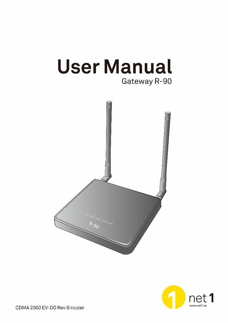
1 Introduction Thank you for purchasing the Net1 R-90 EV-DO router with Voice over IP (VoIP). This user manual will help you setup, configure and outline best practices for maximizing your wireless home network performance with the router.
2 Product Overview In minutes, you will be able to connect your computers to the Internet, share your Internet connection and network your computers. And you will be able to make a call using VoIP. The following is a list of features that make your new Net1 EV-DO router an ideal solution for your home or small office network. Implementation of these features depends on the particular service provider and account features you have chosen. Some features described in this manual may not be supported by your service provider or may not be available with your network account. For details of the services and accounts available, contact your service provider. VoIP Calling Your router (R-90) features a Voice over Internet Protocol (VoIP) function that allows you to make voice calls over a VoIP network by simply connecting a wired, landline phone to your network-connected router. Plug-and-Play
• Your router was factory-set for compatibility with a particular service provider. Thus, your router operates on radio channels and enables services specific to your network service provider. Once your router has been activated on your service provider’s network, you can connect to the Internet. After your router is activated, connect it to your computer using the Ethernet (RJ-45) cable or via Wi-Fi. You are now ready to use the Internet.
Web-Based Advanced User Interface
You can easily setup the router’s advanced functions through your web browser and without having to install additional software onto your computer. There are no drivers to install and, you can easily make changes and perform setup functions from any computer that is connected to your R-90
• NAT IP Address Sharing
• Support for VPN Pass Through
• Built in Dynamic Host Configuration Protocol (DHCP)
• Integrated 802.11b/g/n Wireless Access Point
• MAC Address Filtering
Integrated 10/100 4-Port Switch The R-90 has a built-in, 4-port network switch to allow your wired computers to share printers, data and MP3 files, digital photos, and much more. The switch features automatic detection so it will adjust to the speed of connected devices. The switch will transfer data between computers and the Internet simultaneously without interrupting or consuming resources.
Integrated 802.11 b/g/n Wireless Access Point The R-90 supports Wi-Fi modes b/g and n. Your router as default is set to Wi-Fi mode g. To use mode n you can change this by logging into the web interface (instructions are in section 3.10). Although, please ensure that your Wi-Fi card supports n mode.
R-90 Series
5
2.1 Placement of your R-90
Place your R-90, the central connection point of your network, as close as possible to windows or in rooms at the outer side of your house. If you also use the Wi-Fi feature of the R-90, it should be placed near the centre of your wireless network devices. To achieve the best wireless network coverage: ♦ Ensure that your R-90’s networking antennas are parallel to each other, and are positioned vertically
(toward the ceiling). If your R-90 itself is positioned vertically, point the antennas as much as possible in an upward direction. In multi-storey homes, place the R-90 on an upper floor.
♦ Avoid placing your R-90 near devices that may emit radio “noise,” such as microwave ovens. Dense objects can interfere with wireless communication
♦ If your wireless signal seems weak in some areas, try to move the R-90 to another location while observing the signal strength indicator
R-90 Series
6
3 Using your Router 3.1 Package Contents
• R-90 EV-DO Rev B router
• Antennas
• RJ-45 Ethernet Networking Cable
• Power Supply (230V)
• Car Charger (12V)
• Quick Installation Guide
• CD with Complete User Manual
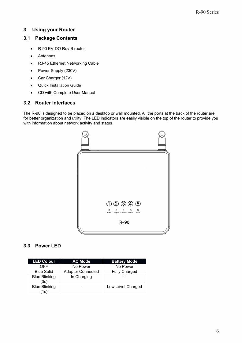
3.2 Router Interfaces
The R-90 is designed to be placed on a desktop or wall mounted. All the ports at the back of the router are for better organization and utility. The LED indicators are easily visible on the top of the router to provide you with information about network activity and status.
3.3 Power LED
LED Colour AC Mode Battery Mode
OFF No Power No Power Blue Solid Adaptor Connected Fully Charged
Blue Blinking (3s)
In Charging -
Blue Blinking (1s)
- Low Level Charged
R-90 Series
7
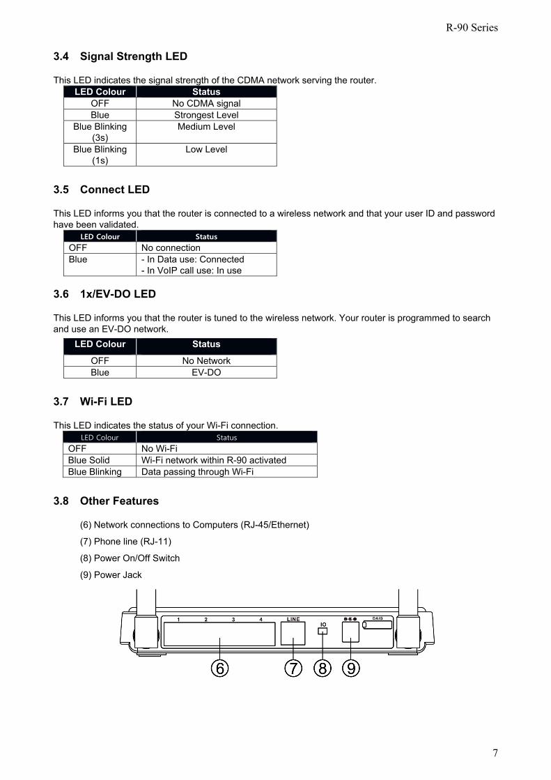
3.4 Signal Strength LED
This LED indicates the signal strength of the CDMA network serving the router. LED Colour Status
OFF No CDMA signal Blue Strongest Level
Blue Blinking (3s)
Medium Level
Blue Blinking (1s)
Low Level
3.5 Connect LED
This LED informs you that the router is connected to a wireless network and that your user ID and password have been validated.
LED Colour Status
OFF No connection Blue - In Data use: Connected
- In VoIP call use: In use 3.6 1x/EV-DO LED
This LED informs you that the router is tuned to the wireless network. Your router is programmed to search and use an EV-DO network.
LED Colour Status
OFF No Network Blue EV-DO
3.7 Wi-Fi LED
This LED indicates the status of your Wi-Fi connection. LED Colour Status
OFF No Wi-Fi Blue Solid Wi-Fi network within R-90 activated Blue Blinking Data passing through Wi-Fi
3.8 Other Features
(6) Network connections to Computers (RJ-45/Ethernet)
(7) Phone line (RJ-11)
(8) Power On/Off Switch
(9) Power Jack
R-90 Series
8
3.9 Setting up your hardware
1 Make sure your router is not connected to any power source and that all the LEDs are OFF.
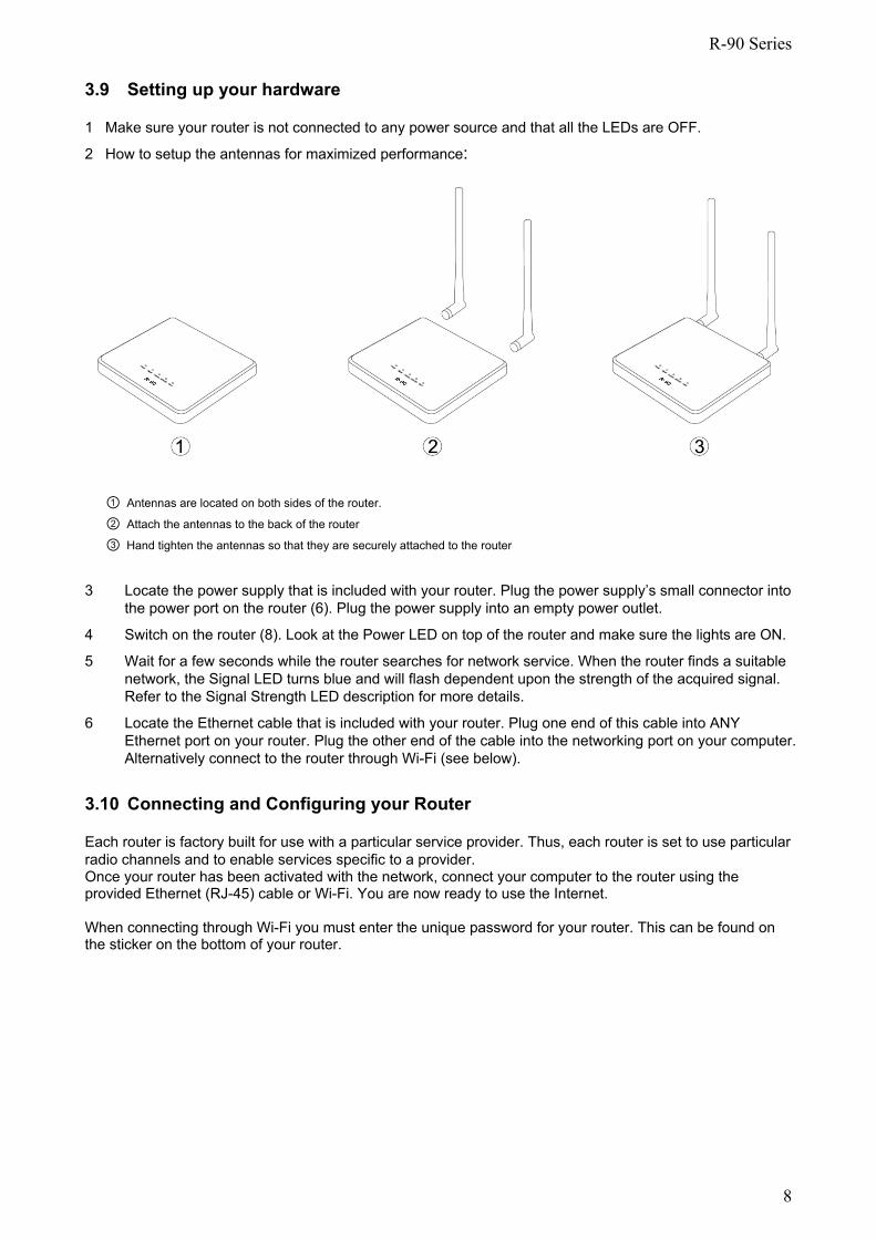
2 How to setup the antennas for maximized performance:
① Antennas are located on both sides of the router.
② Attach the antennas to the back of the router
③ Hand tighten the antennas so that they are securely attached to the router 3 Locate the power supply that is included with your router. Plug the power supply’s small connector into
the power port on the router (6). Plug the power supply into an empty power outlet.
4 Switch on the router (8). Look at the Power LED on top of the router and make sure the lights are ON.
5 Wait for a few seconds while the router searches for network service. When the router finds a suitable network, the Signal LED turns blue and will flash dependent upon the strength of the acquired signal. Refer to the Signal Strength LED description for more details.
6 Locate the Ethernet cable that is included with your router. Plug one end of this cable into ANY Ethernet port on your router. Plug the other end of the cable into the networking port on your computer. Alternatively connect to the router through Wi-Fi (see below).
3.10 Connecting and Configuring your Router
Each router is factory built for use with a particular service provider. Thus, each router is set to use particular radio channels and to enable services specific to a provider. Once your router has been activated with the network, connect your computer to the router using the provided Ethernet (RJ-45) cable or Wi-Fi. You are now ready to use the Internet. When connecting through Wi-Fi you must enter the unique password for your router. This can be found on the sticker on the bottom of your router.
R-90 Series
9
4 Web Manager Options
The Web Manager User Interface is a web-based tool that you can use to setup the router. You can also use it to manage advanced functions of your router. From the User Interface, you can perform these tasks:
• View the router’s current settings and status
• Change Wi-Fi name, encryption and password
• Configure the router's router and VoIP account log-in function to connect to your Service Provider using the settings that they provided you
• Change current network settings such as the internal IP address, IP address pool, DHCP settings and more
• Set the router’s firewall to work with specific applications (port forwarding)
• Setup security features such as client restrictions, MAC address filtering, WEP and WPA
• Enable the DMZ feature for a single computer on your network
• Change the router’s internal password
• Reboot the router
• Back up your configuration settings
• Reset the router’s default settings
• Update the router’s firmware
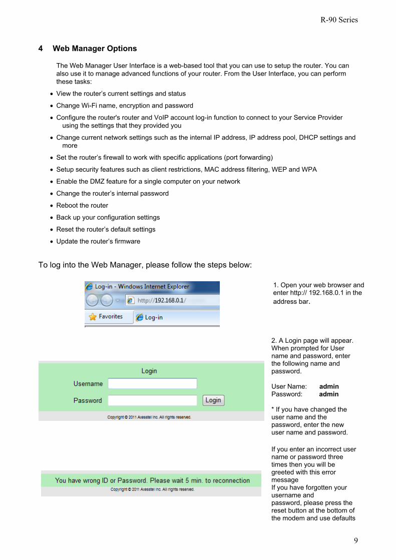
To log into the Web Manager, please follow the steps below:
1. Open your web browser and enter http:// 192.168.0.1 in the address bar.
2. A Login page will appear. When prompted for User name and password, enter the following name and password. User Name: admin Password: admin * If you have changed the user name and the password, enter the new user name and password.
If you enter an incorrect user name or password three times then you will be greeted with this error message If you have forgotten your username and password, please press the reset button at the bottom of the modem and use defaults
R-90 Series
10
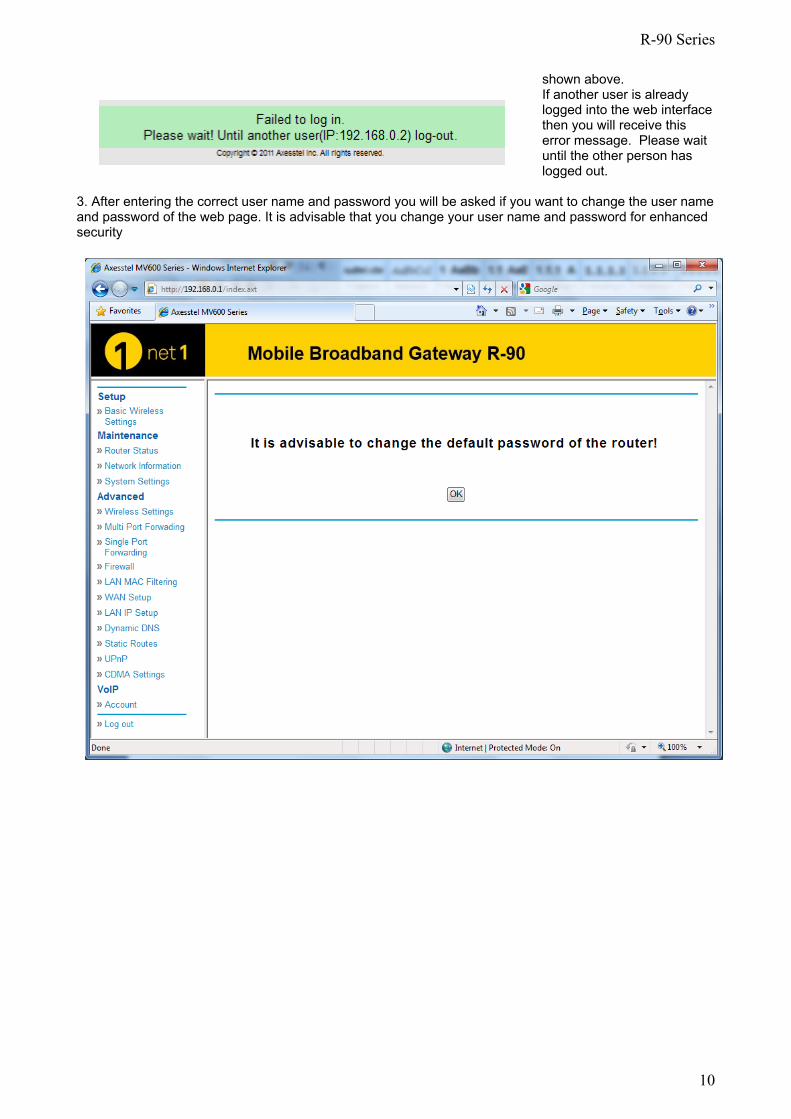
shown above.
If another user is already logged into the web interface then you will receive this error message. Please wait until the other person has logged out.
3. After entering the correct user name and password you will be asked if you want to change the user name and password of the web page. It is advisable that you change your user name and password for enhanced security
R-90 Series
11
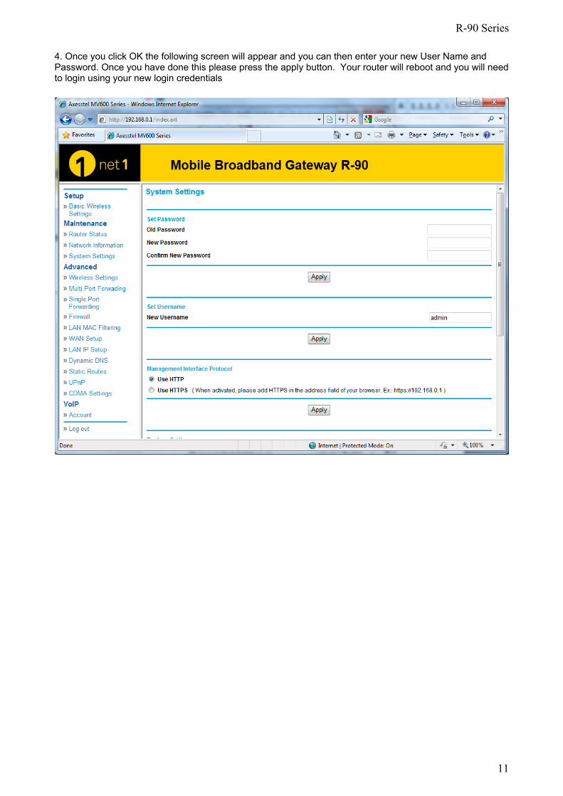
4. Once you click OK the following screen will appear and you can then enter your new User Name and Password. Once you have done this please press the apply button. Your router will reboot and you will need to login using your new login credentials
R-90 Series
12
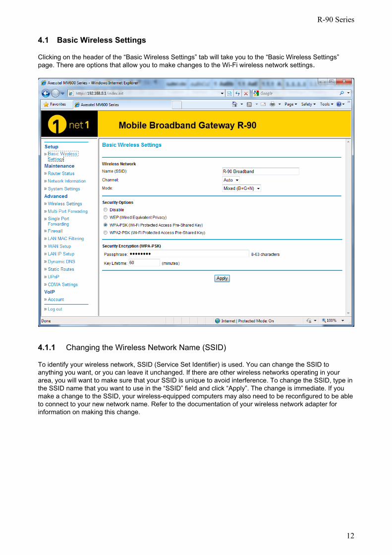
4.1 Basic Wireless Settings
Clicking on the header of the “Basic Wireless Settings” tab will take you to the “Basic Wireless Settings” page. There are options that allow you to make changes to the Wi-Fi wireless network settings.
4.1.1 Changing the Wireless Network Name (SSID)
To identify your wireless network, SSID (Service Set Identifier) is used. You can change the SSID to anything you want, or you can leave it unchanged. If there are other wireless networks operating in your area, you will want to make sure that your SSID is unique to avoid interference. To change the SSID, type in the SSID name that you want to use in the “SSID” field and click “Apply”. The change is immediate. If you make a change to the SSID, your wireless-equipped computers may also need to be reconfigured to be able to connect to your new network name. Refer to the documentation of your wireless network adapter for information on making this change.
R-90 Series
13
4.1.2 Selecting the Wireless Channel
Your router as default is pre-configured to choose the best wireless channel. It does this by looking at the channels that are being used by Wi-Fi networks and choosing the best channel accordingly. If needed this channel can be changed.
4.1.3 Wi-Fi Mode Your R-90 can support three different types of Wi-Fi network, types b, g and n. As default the R-90 is set to support mixed mode (b/g/n). This setting ensures that nearly all Wi-Fi devices will be able to connect to your R-90 without any issues
4.1.4 Securing your Wi-Fi Network
There are a few different ways you can maximize the security of your wireless network and protect your data from prying eyes and ears. Three encryption methods are available.
• WEP (Wired Equivalent Privacy)
• WPA (Wi-Fi Protected Access) – PSK
• WPA 2 (Wi-Fi Protected Access 2) – PSK
R-90 Series
14
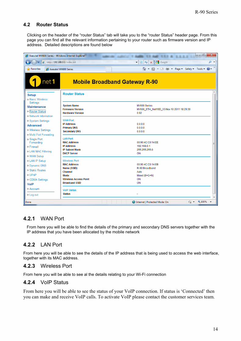
4.2 Router Status
Clicking on the header of the “router Status” tab will take you to the “router Status” header page. From this page you can find all the relevant information pertaining to your router such as firmware version and IP address. Detailed descriptions are found below
4.2.1 WAN Port From here you will be able to find the details of the primary and secondary DNS servers together with the IP address that you have been allocated by the mobile network
4.2.2 LAN Port From here you will be able to see the details of the IP address that is being used to access the web interface, together with its MAC address.
4.2.3 Wireless Port From here you will be able to see al the details relating to your Wi-Fi connection
4.2.4 VoIP Status From here you will be able to see the status of your VoIP connection. If status is ‘Connected’ then you can make and receive VoIP calls. To activate VoIP please contact the customer services team.
R-90 Series
15
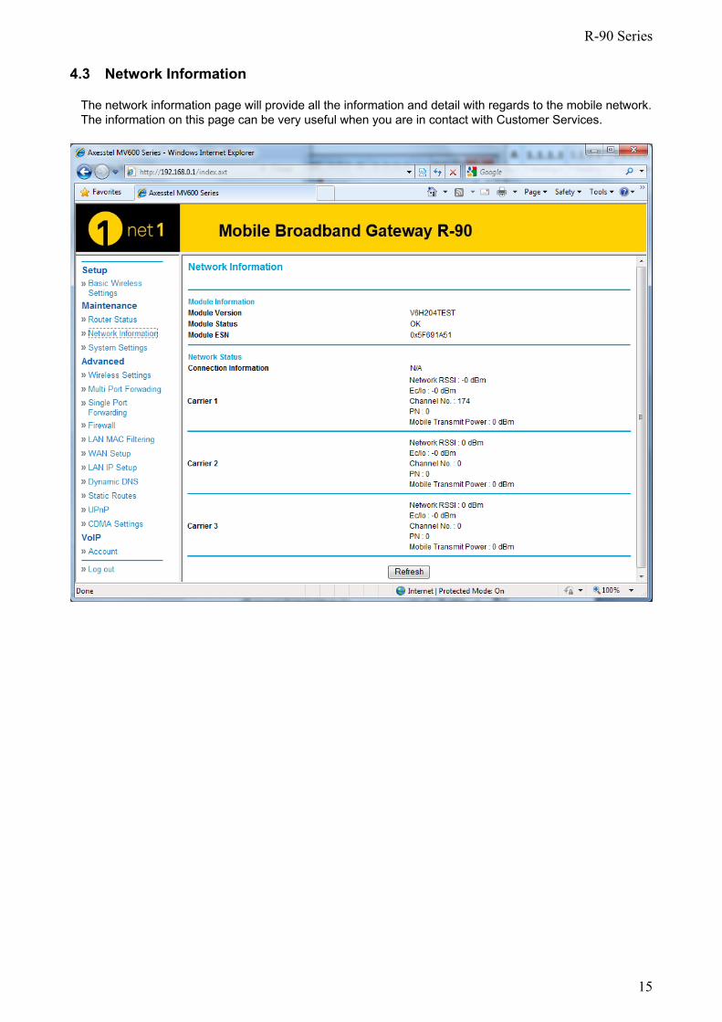
4.3 Network Information
The network information page will provide all the information and detail with regards to the mobile network. The information on this page can be very useful when you are in contact with Customer Services.
R-90 Series
16
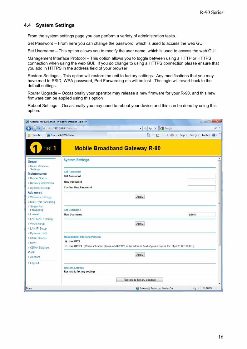
4.4 System Settings
From the system settings page you can perform a variety of administration tasks.
Set Password – From here you can change the password, which is used to access the web GUI
Set Username – This option allows you to modify the user name, which is used to access the web GUI
Management Interface Protocol – This option allows you to toggle between using a HTTP or HTTPS connection when using the web GUI. If you do change to using a HTTPS connection please ensure that you add in HTTPS in the address field of your browser
Restore Settings – This option will restore the unit to factory settings. Any modifications that you may have mad to SSID, WPA password, Port Forwarding etc will be lost. The login will revert back to the default settings.
Router Upgrade – Occasionally your operator may release a new firmware for your R-90, and this new firmware can be applied using this option
Reboot Settings – Occasionally you may need to reboot your device and this can be done by using this option.
R-90 Series
17
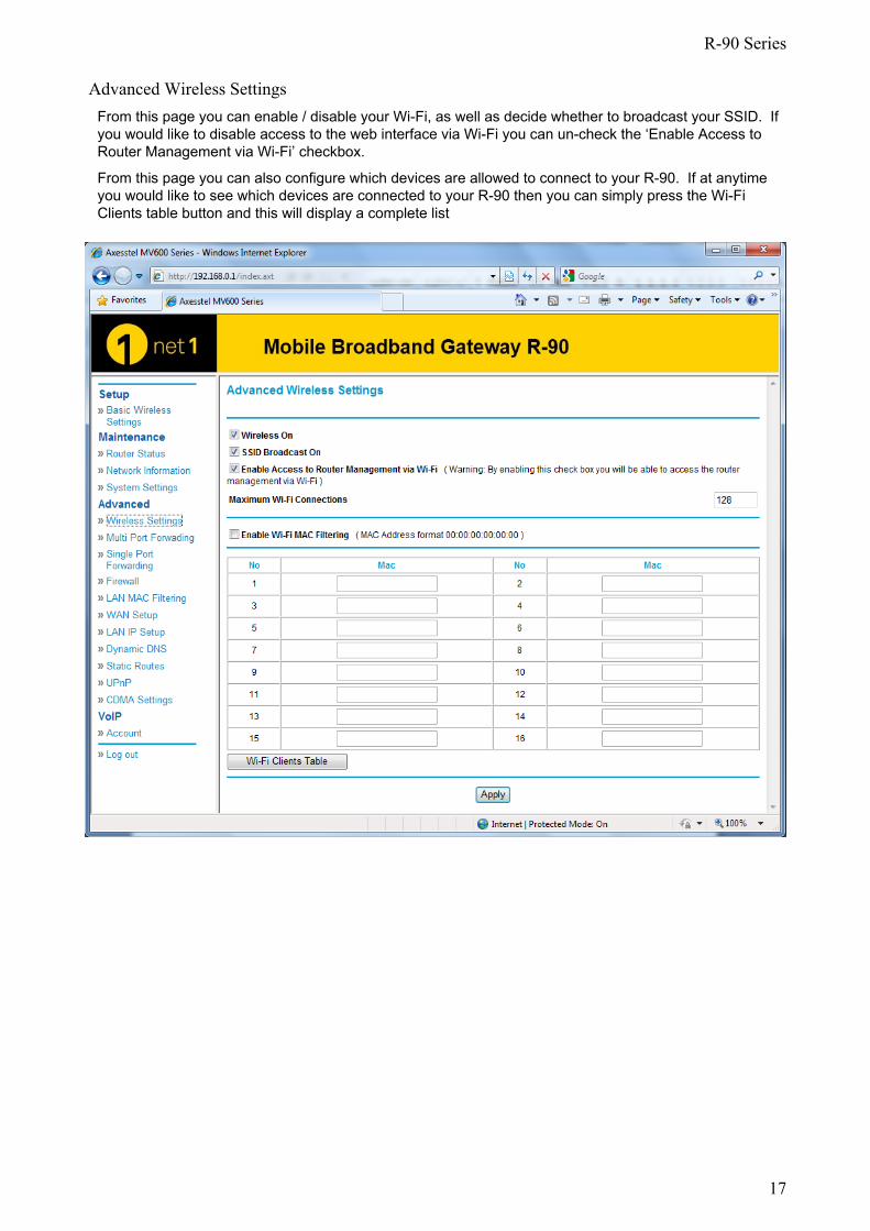
Advanced Wireless Settings From this page you can enable / disable your Wi-Fi, as well as decide whether to broadcast your SSID. If you would like to disable access to the web interface via Wi-Fi you can un-check the ‘Enable Access to Router Management via Wi-Fi’ checkbox.
From this page you can also configure which devices are allowed to connect to your R-90. If at anytime you would like to see which devices are connected to your R-90 then you can simply press the Wi-Fi Clients table button and this will display a complete list
R-90 Series
18
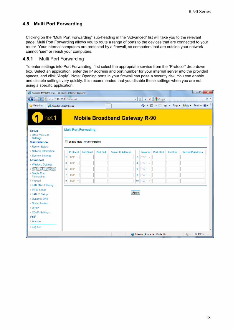
4.5 Multi Port Forwarding
Clicking on the “Multi Port Forwarding” sub-heading in the “Advanced” list will take you to the relevant page. Multi Port Forwarding allows you to route a range of ports to the devices that are connected to your router. Your internal computers are protected by a firewall, so computers that are outside your network cannot “see” or reach your computers.
4.5.1 Multi Port Forwarding To enter settings into Port Forwarding, first select the appropriate service from the “Protocol” drop-down box. Select an application, enter the IP address and port number for your internal server into the provided spaces, and click “Apply”. Note: Opening ports in your firewall can pose a security risk. You can enable and disable settings very quickly. It is recommended that you disable these settings when you are not using a specific application.
R-90 Series
19
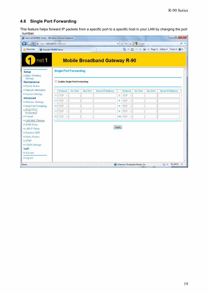
4.6 Single Port Forwarding
This feature helps forward IP packets from a specific port to a specific host in your LAN by changing the port number.
R-90 Series
20
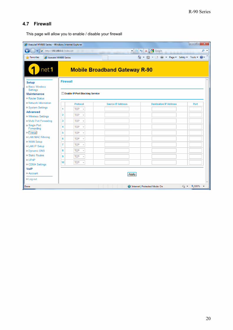
4.7 Firewall
This page will allow you to enable / disable your firewall
R-90 Series
21
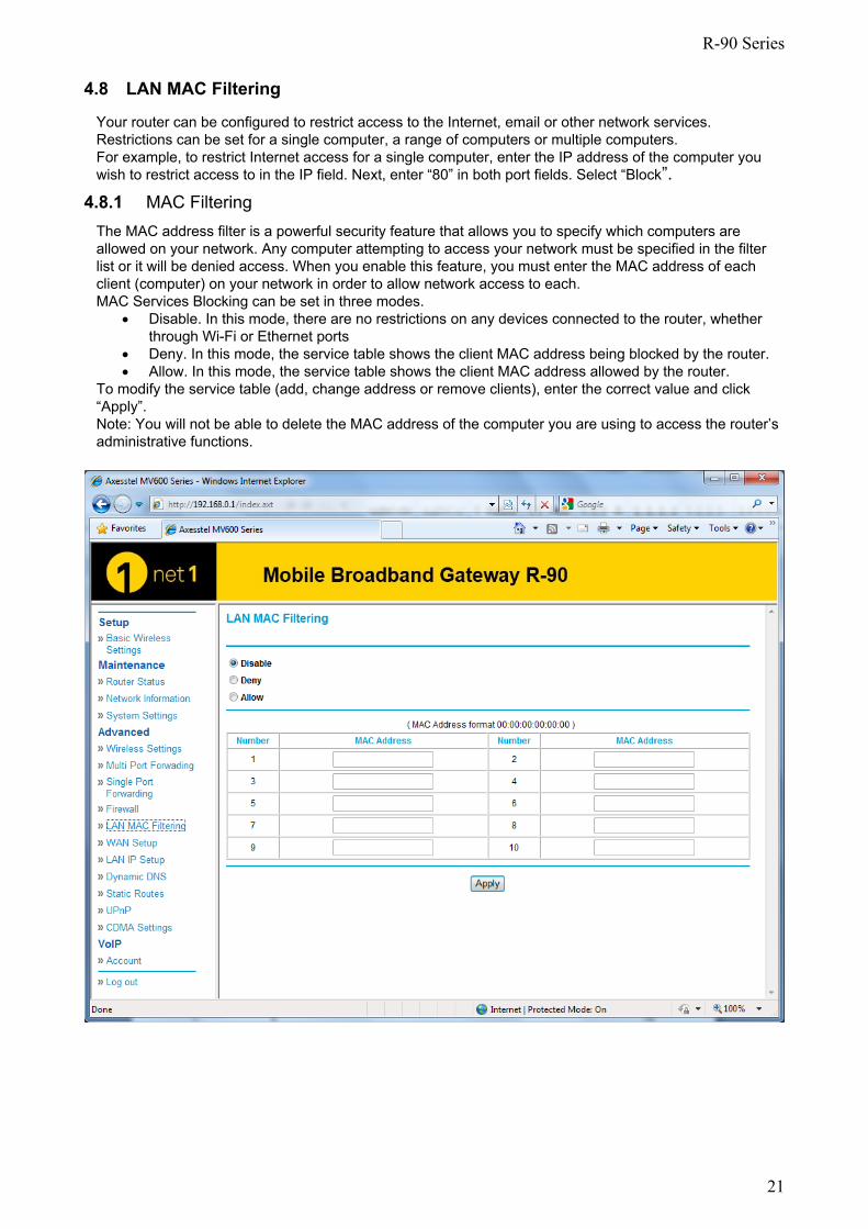
4.8 LAN MAC Filtering
Your router can be configured to restrict access to the Internet, email or other network services. Restrictions can be set for a single computer, a range of computers or multiple computers. For example, to restrict Internet access for a single computer, enter the IP address of the computer you wish to restrict access to in the IP field. Next, enter “80” in both port fields. Select “Block”.
4.8.1 MAC Filtering The MAC address filter is a powerful security feature that allows you to specify which computers are allowed on your network. Any computer attempting to access your network must be specified in the filter list or it will be denied access. When you enable this feature, you must enter the MAC address of each client (computer) on your network in order to allow network access to each. MAC Services Blocking can be set in three modes.
• Disable. In this mode, there are no restrictions on any devices connected to the router, whether through Wi-Fi or Ethernet ports
• Deny. In this mode, the service table shows the client MAC address being blocked by the router. • Allow. In this mode, the service table shows the client MAC address allowed by the router.
To modify the service table (add, change address or remove clients), enter the correct value and click “Apply”. Note: You will not be able to delete the MAC address of the computer you are using to access the router’s administrative functions.
R-90 Series
22
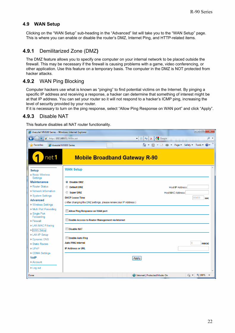
4.9 WAN Setup
Clicking on the “WAN Setup” sub-heading in the “Advanced” list will take you to the “WAN Setup” page. This is where you can enable or disable the router’s DMZ, Internet Ping, and HTTP-related items.
4.9.1 Demilitarized Zone (DMZ) The DMZ feature allows you to specify one computer on your internal network to be placed outside the firewall. This may be necessary if the firewall is causing problems with a game, video conferencing, or other application. Use this feature on a temporary basis. The computer in the DMZ is NOT protected from hacker attacks.
4.9.2 WAN Ping Blocking Computer hackers use what is known as “pinging” to find potential victims on the Internet. By pinging a specific IP address and receiving a response, a hacker can determine that something of interest might be at that IP address. You can set your router so it will not respond to a hacker’s ICMP ping, increasing the level of security provided by your router. If it is necessary to turn on the ping response, select “Allow Ping Response on WAN port” and click “Apply”.
4.9.3 Disable NAT This feature disables all NAT router functionality.
R-90 Series
23
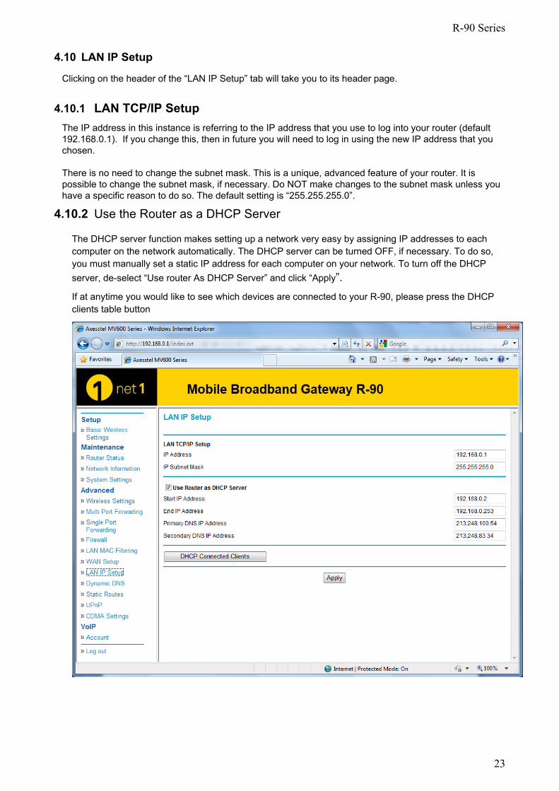
4.10 LAN IP Setup
Clicking on the header of the “LAN IP Setup” tab will take you to its header page.
4.10.1 LAN TCP/IP Setup The IP address in this instance is referring to the IP address that you use to log into your router (default 192.168.0.1). If you change this, then in future you will need to log in using the new IP address that you chosen. There is no need to change the subnet mask. This is a unique, advanced feature of your router. It is possible to change the subnet mask, if necessary. Do NOT make changes to the subnet mask unless you have a specific reason to do so. The default setting is “255.255.255.0”.
4.10.2 Use the Router as a DHCP Server
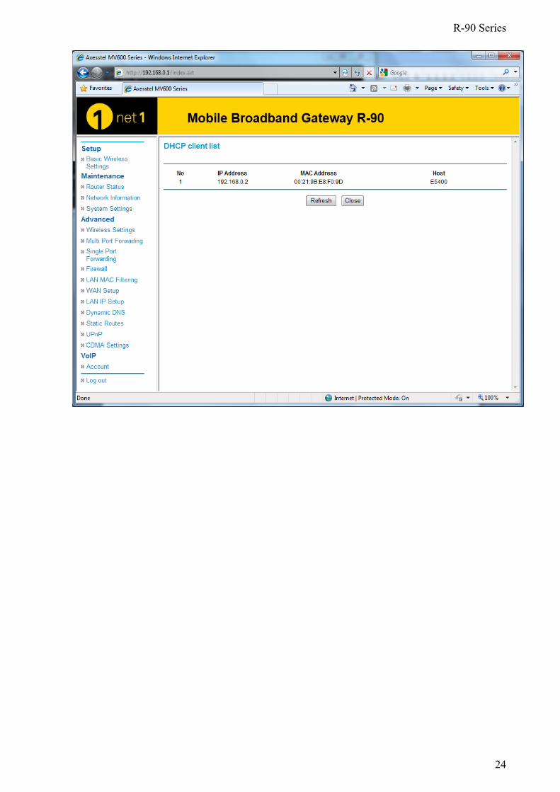
The DHCP server function makes setting up a network very easy by assigning IP addresses to each computer on the network automatically. The DHCP server can be turned OFF, if necessary. To do so, you must manually set a static IP address for each computer on your network. To turn off the DHCP server, de-select “Use router As DHCP Server” and click “Apply”. If at anytime you would like to see which devices are connected to your R-90, please press the DHCP clients table button
R-90 Series
24
R-90 Series
25
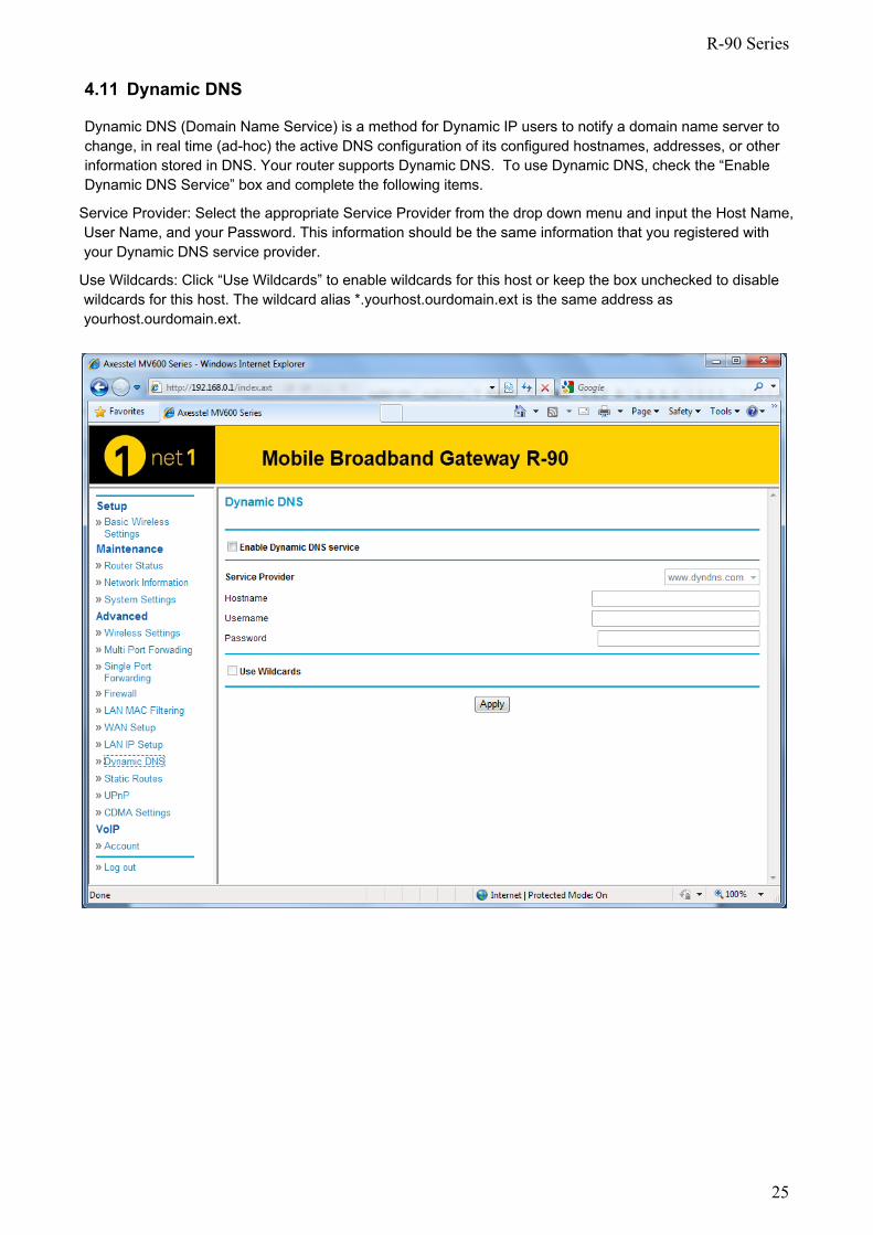
4.11 Dynamic DNS
Dynamic DNS (Domain Name Service) is a method for Dynamic IP users to notify a domain name server to change, in real time (ad-hoc) the active DNS configuration of its configured hostnames, addresses, or other information stored in DNS. Your router supports Dynamic DNS. To use Dynamic DNS, check the “Enable Dynamic DNS Service” box and complete the following items.
Service Provider: Select the appropriate Service Provider from the drop down menu and input the Host Name, User Name, and your Password. This information should be the same information that you registered with your Dynamic DNS service provider.
Use Wildcards: Click “Use Wildcards” to enable wildcards for this host or keep the box unchecked to disable wildcards for this host. The wildcard alias *.yourhost.ourdomain.ext is the same address as yourhost.ourdomain.ext.
R-90 Series
26
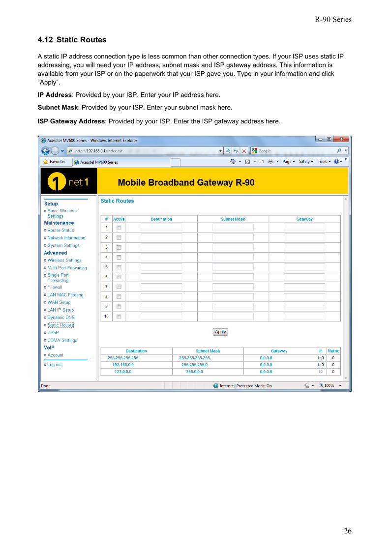
4.12 Static Routes
A static IP address connection type is less common than other connection types. If your ISP uses static IP addressing, you will need your IP address, subnet mask and ISP gateway address. This information is available from your ISP or on the paperwork that your ISP gave you. Type in your information and click “Apply”.
IP Address: Provided by your ISP. Enter your IP address here.
Subnet Mask: Provided by your ISP. Enter your subnet mask here.
ISP Gateway Address: Provided by your ISP. Enter the ISP gateway address here.
R-90 Series
27
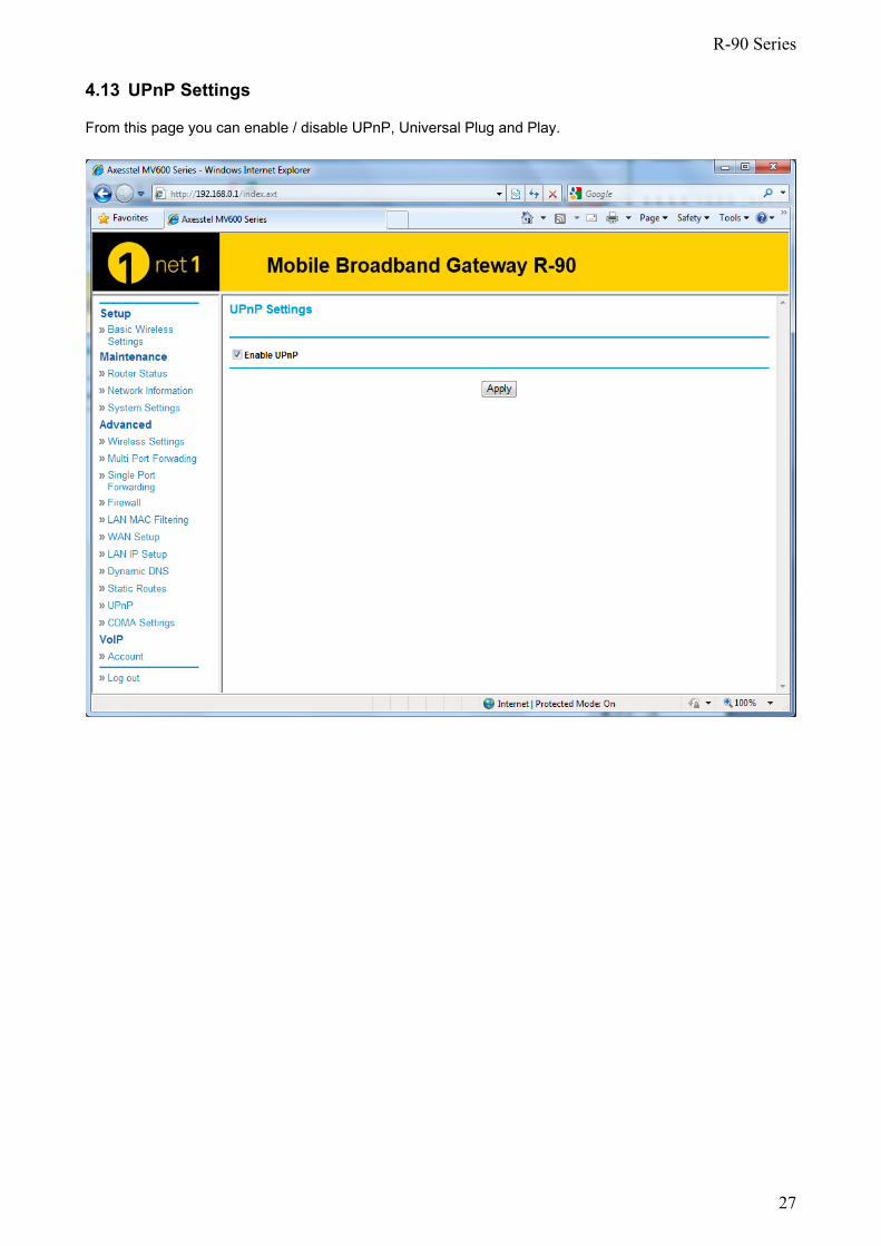
4.13 UPnP Settings
From this page you can enable / disable UPnP, Universal Plug and Play.
R-90 Series
28
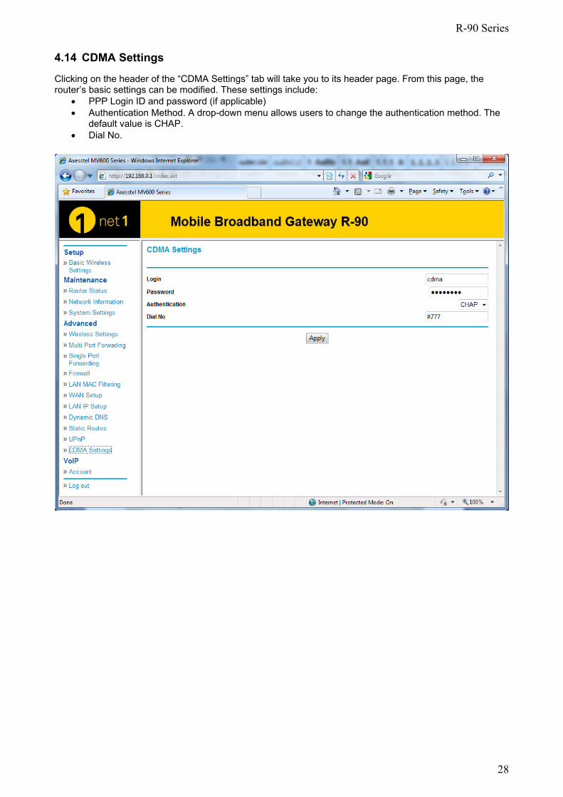
4.14 CDMA Settings
Clicking on the header of the “CDMA Settings” tab will take you to its header page. From this page, the router’s basic settings can be modified. These settings include:
• PPP Login ID and password (if applicable) • Authentication Method. A drop-down menu allows users to change the authentication method. The
default value is CHAP. • Dial No.
R-90 Series
29
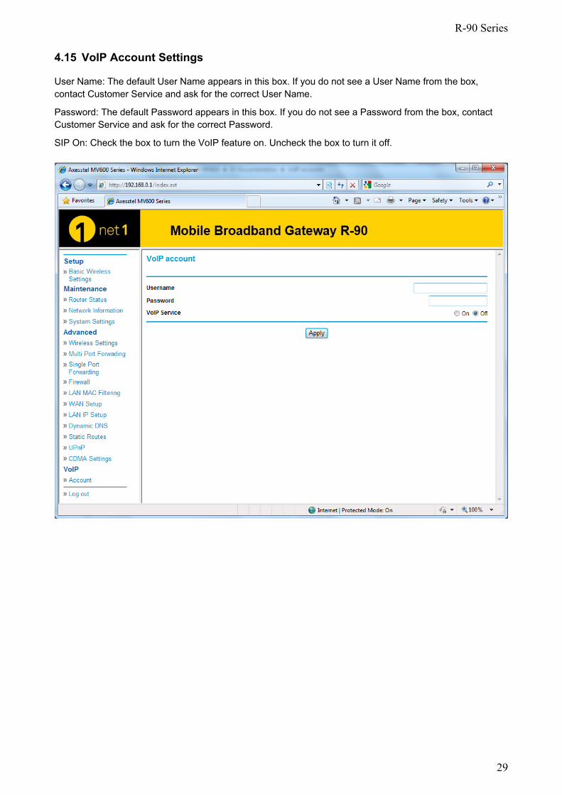
4.15 VoIP Account Settings
User Name: The default User Name appears in this box. If you do not see a User Name from the box, contact Customer Service and ask for the correct User Name.
Password: The default Password appears in this box. If you do not see a Password from the box, contact Customer Service and ask for the correct Password.
SIP On: Check the box to turn the VoIP feature on. Uncheck the box to turn it off.
R-90 Series
30
5 VoIP Call Functions
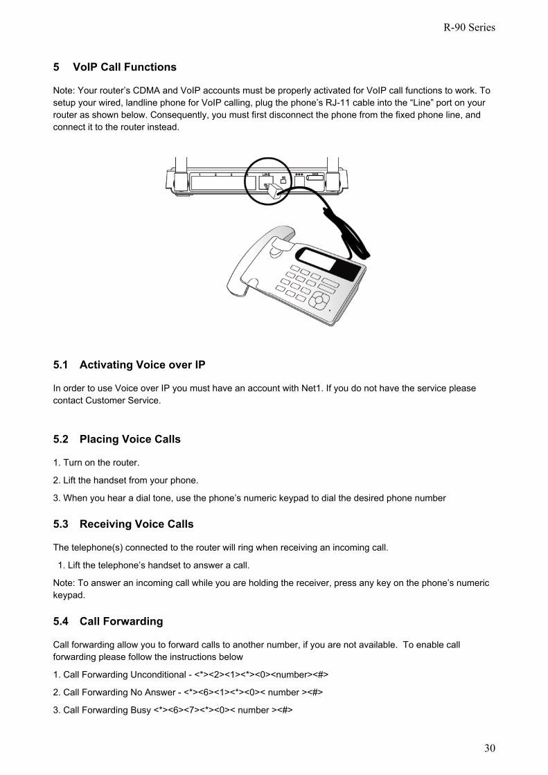
Note: Your router’s CDMA and VoIP accounts must be properly activated for VoIP call functions to work. To setup your wired, landline phone for VoIP calling, plug the phone’s RJ-11 cable into the “Line” port on your router as shown below. Consequently, you must first disconnect the phone from the fixed phone line, and connect it to the router instead.
5.1 Activating Voice over IP
In order to use Voice over IP you must have an account with Net1. If you do not have the service please contact Customer Service. 5.2 Placing Voice Calls
1. Turn on the router.
2. Lift the handset from your phone.
3. When you hear a dial tone, use the phone’s numeric keypad to dial the desired phone number 5.3 Receiving Voice Calls
The telephone(s) connected to the router will ring when receiving an incoming call.
1. Lift the telephone’s handset to answer a call.
Note: To answer an incoming call while you are holding the receiver, press any key on the phone’s numeric keypad. 5.4 Call Forwarding
Call forwarding allow you to forward calls to another number, if you are not available. To enable call forwarding please follow the instructions below
1. Call Forwarding Unconditional - <*><2><1><*><0><number><#>
2. Call Forwarding No Answer - <*><6><1><*><0>< number ><#>
3. Call Forwarding Busy <*><6><7><*><0>< number ><#>
R-90 Series
31
5.5 Restricting Caller Line Identification
Your phone number will automatically be sent whenever a call is made. To stop your number being sent by the network please enter the following before your call *31*. You will have to enter this number before every call.
R-90 Series
32
6 Troubleshooting Problem Solution
I am unable to connect to the Internet. The R-90’s “Signal” light is on and the “Connect” light is off
Please ensure that you are connected to your R-90. If you are using Wi-Fi please try to connect via an Ethernet cable to the R-90 to see if that resolves the issue. If you are using a third party firewall, please disable this firewall as this could be interfering with the connection. Another solution maybe to reboot your router. Alternatively please contact customer services if neither of the above resolve your problem
I can’t connect to the Internet wirelessly from my computer but it works if I use the Ethernet cable.
Please check to see if the Wi-Fi LED is on. If it is off please log into the web interface (see section 4) an enable Wi-Fi. If the LED is on then please check that your computer is in range of the R-90, and that you are connected to the correct Wi-Fi device
My wireless network performance is inconsistent, data transfer is sometimes slow and my Wi-Fi signal strength is poor.
Wireless technology is radio-based, which means connectivity and the throughput performance between devices decreases when the distance between devices increases. Other external factors can cause signal degradation such as walls and metal appliances. Your connection speed may decrease as you move farther away from the R-90 or access point. In order to determine if wireless issues are related to range, we suggest temporarily moving the computer, if possible, only a few meters away from the R-90 to see if the data rate improves
My internet speed is slow and my Signal LED is flashing every 1-second.
If your signal LED is flashing blue this means that the device is not receiving good signal from the mobile network. Please try to move the R-90 to near a window to see if this improves the data rate. You have good signal when the signal led starts to flash at a slower speed or the signal led remains fixed.
R-90 Series
33
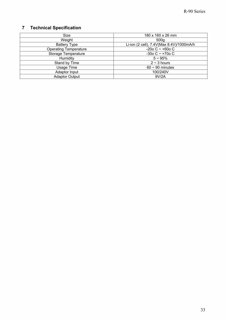
7 Technical Specification Size 180 x 160 x 26 mm
Weight 500g Battery Type Li-ion (2 cell), 7.4V(Max 8.4V)/1000mA/h
Operating Temperature -20o C ~ +60o C Storage Temperature -30o C ~ +70o C
Humidity 5 ~ 95% Stand by Time 2 ~ 3 hours Usage Time 60 ~ 90 minutes
Adaptor Input 100/240V Adaptor Output 9V/2A
R-90 Series
34
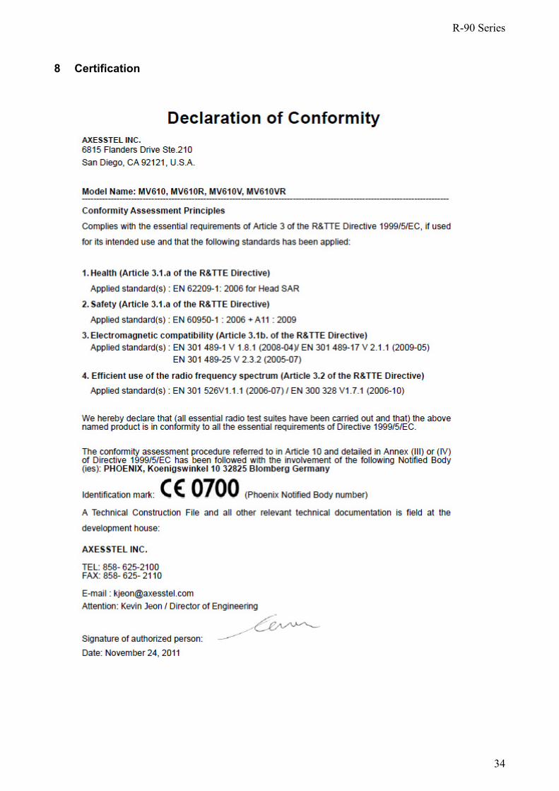
8 Certification
Related Documents