Manchester Coding Basics When beginning to work with communication systems, it is important to first under- stand a few basic terms that are used, Modulation and Coding. These are often used interchangeably which leads to many errors because they refer to completely different aspects of the communication. It is very important to observe and fully understand the application and implementation of these two aspects of communication theory. This application note will be focused on the Coding and Decoding. But, before we address this, we need to look at what must be done to send a message or data through our communication system. 1. Modulation Modulation refers to the act of adding the message signal to some form of carrier. The carrier, by definition, is a higher frequency signal whose phase, frequency, amplitude, or some combination thereof, is varied proportionally to the message. This change can be detected and recovered (demodulated) at the other end of the communication channel. There are a number of ways this can be done but for simplicity we will only look at Amplitude Modulation (AM), On-Off Keying (a variation on AM), and Frequency Modulation (FM). Modulation is typically carried out in hardware, but that subject is beyond the scope of this document. 1.1 Amplitude Modulation In amplitude modulation, the amplitude of the carrier is changed to follow the message signal. In this case we can see a “ripple” on the carrier, its envelope contains the mes- sage. This can be demodulated using an extremely simple envelope detector that captures this ripple as a low frequency response. 1.2 On-Off Keying This form of modulation takes the amplitude modulation as described above to the extreme. In this instance, we have only two states: Carrier and No Carrier. This approach lends itself nicely to the transmission of digital data because the carrier can be simply switched “on” or “off” depending on the state of the data being sent. The demodulated output is either high or low depending on the presence of the carrier. Manchester Coding Basics Application Note 9164A–AUTO–09/09

Welcome message from author
This document is posted to help you gain knowledge. Please leave a comment to let me know what you think about it! Share it to your friends and learn new things together.
Transcript

Manchester Coding Basics
Application Note
9164A–AUTO–09/09
Manchester Coding Basics
When beginning to work with communication systems, it is important to first under-stand a few basic terms that are used, Modulation and Coding. These are often usedinterchangeably which leads to many errors because they refer to completely differentaspects of the communication. It is very important to observe and fully understand theapplication and implementation of these two aspects of communication theory. Thisapplication note will be focused on the Coding and Decoding. But, before we addressthis, we need to look at what must be done to send a message or data through ourcommunication system.
1. ModulationModulation refers to the act of adding the message signal to some form of carrier. Thecarrier, by definition, is a higher frequency signal whose phase, frequency, amplitude,or some combination thereof, is varied proportionally to the message. This changecan be detected and recovered (demodulated) at the other end of the communicationchannel. There are a number of ways this can be done but for simplicity we will onlylook at Amplitude Modulation (AM), On-Off Keying (a variation on AM), and FrequencyModulation (FM). Modulation is typically carried out in hardware, but that subject isbeyond the scope of this document.
1.1 Amplitude ModulationIn amplitude modulation, the amplitude of the carrier is changed to follow the messagesignal. In this case we can see a “ripple” on the carrier, its envelope contains the mes-sage. This can be demodulated using an extremely simple envelope detector thatcaptures this ripple as a low frequency response.
1.2 On-Off KeyingThis form of modulation takes the amplitude modulation as described above to theextreme. In this instance, we have only two states: Carrier and No Carrier. Thisapproach lends itself nicely to the transmission of digital data because the carrier canbe simply switched “on” or “off” depending on the state of the data being sent. Thedemodulated output is either high or low depending on the presence of the carrier.

1.3 Frequency ModulationFrequency modulation is more complicated but provides the benefit of constant output powerindependent of the message being sent. With this approach, the frequency of the carrier is notconstant but varies in relation to the message. This requires a much more complicateddemodulation circuit typically implemented using a Phase Lock Loop (PLL).
1.4 Frequency Shift Keying The relationship between Frequency Shift Keying and Frequency Modulation is analogous tothe relationship between On-Off Keying and Amplitude Modulation in that only two carrier fre-quencies are used, each corresponding to a digital state. In this case, the benefits ofFrequency Modulation are realized but with less complexity in the demodulation circuit.
2. Coding TechniquesHaving reviewed the common modulation techniques in the previous sections, it should benoted that all of the techniques deal with how the message signal was impressed onto a car-rier. Modulation did not address how the message signal was created from the data to be sent.Coding defines how we accurately, efficiently, and robustly construct a message signal fromthe data we desire to communicate. Just like modulation, there are a vast number of ways tocode data, each having unique qualities and attributes and each can be chosen to optimizecertain aspects in the desired system. We will briefly cover a few coding methods, NRZ andBiPhase, before looking at the primary topic of this article, Manchester. Also it should be men-tioned that we are simply looking at coding digital (binary) information to create the message.Although coding can be implemented in hardware, we are going to look at how this is achievedthrough software. We will assume our encoded/decoded message signal will be present on anoutput/input pin of a microcontroller.
2.1 NRZ NRZ is one of the most basic of coding schemes. In this method the message signal does NotReturn to Zero after each bit frame. This means that the message exactly follows the digitaldata structure. For example, a long data string of “1”s will produce a long high period in themessage signal. Transitions only occur in the message when there is a logical bit change (seeFigure 2-1 on page 3).
This is a very easy method to implement on the encoding side but requires the data rate to beknown exactly on the receiving side in order to be decoded. Any mismatch in data clock tim-ings will result in erroneous data that is only detectable with some error detection such as achecksum or CRC. Also errors from the communication channel or interference will not bedetected without some form of data integrity checks.
29164A–AUTO–09/09
Manchester Coding Basics

Manchester Coding Basics
2.2 BiPhaseBiPhase adds a level of complexity to the coding process but in return includes a way to trans-fer the bit frame data clock that can be used in the decoding to increase accuracy. BiPhasecoding says that there will be a state transition in the message signal at the end of every bitframe. In addition, a logical “1” will have an additional transition at the mid-bit (see Figure 2-1on page 3). This allows the demodulation system to recover the data rate and also synchro-nize to the bit edge periods. With this clock information, the data stream can be recreated.This is similar to the method we will describe next.
2.3 ManchesterManchester coding is one of the most common data coding methods used today. Similar toBiPhase, Manchester coding provides a means of adding the data rate clock to the messageto be used on the receiving end. Also Manchester provides the added benefit of always yield-ing an average DC level of 50%. This has positive implications in the demodulator's circuitdesign as well as managing transmitted RF spectrum after modulation. This means that inmodulation types where the power output is a function of the message such as AM, the aver-age power is constant and independent of the data stream being encoded. Manchester codingstates that there will always be a transition of the message signal at the mid-point of the databit frame. What occurs at the bit edges depends on the state of the previous bit frame anddoes not always produce a transition. A logical “1” is defined as a mid-point transition from lowto high and a “0” is a mid-point transition from high to low (see Figure 2-1). A more thoroughlook at methods to encode and decode data will be shown in detail in the next sections.
Figure 2-1. Encoding Signals
Bit Frame Bit Frame Bit Frame Bit Frame
0 0 0 1
Bit Frame Bit Frame Bit Frame Bit Frame
1 0 1 1
BiPhase
BiPhase
Manchester
NRZ
BiPhase
BiPhase
Manchester
NRZ
39164A–AUTO–09/09

3. Manchester EncodingEncoding is the process of adding the correct transitions to the message signal in relation tothe data that is to be sent over the communication system. The first step is to establish thedata rate that is going to be used. Once this is fixed, then the mid-bit time can be determinedas ½ of the data rate period. In our example we are going to use a data rate of 4 kHz. This pro-vides a bit period of 1/f = 1/4000 = 0.00025s or 250 µs. Dividing by two gives us the mid-bittime (which we will label “T”) of 125 µs. Now let's look at how we use this to encode a databyte of 0xC5 (11000101b). The easiest method to do this is to use a timer set to expire orinterrupt at the T interval. We also need to set up a method to track which ½ bit period we arecurrently sending. Once we do this, we can easily encode the data and output the messagesignal.
1. Begin with the output signal high.
2. Check if all bits have been sent, If yes, then go to step 7
3. Check the next logical bit to be coded
4. If the bit equals “1”, then call ManchesterOne(T)
5. Else call ManchesterZero(T)
6. Return to step 2
7. Set output signal high and return
3.1 Implementation of ManchesterOne(T)1. Set the output signal low
2. Wait for mid-bit time (T)
3. Set the output signal high
4. Wait for mid-bit time (T)
5. Return
3.2 Implementation of ManchesterZero(T)6. Set the output signal high
7. Wait for mid-bit time (T)
8. Set the output signal low
9. Wait for mid-bit time (T)
10. Return
These easy routines will provide an output at the microcontroller pin that exactly encodes thedata into a Manchester message signal at the desired data rate. The accuracy of the data rateand duty cycle depends on the accuracy of the clock source and the method used to createthe wait times. It is recommended to use a timer/counter, and associated interrupts, as shownin the sample code provided in the appendix.
49164A–AUTO–09/09
Manchester Coding Basics

Manchester Coding Basics
4. Manchester DecodingDecoding is where most people attempting to work with Manchester have questions. Thereare several ways to approach this and each has unique benefits. This section will describehow to implement two different methods. To start we will look at the steps that are needed foreither methodology.
1. The data rate clock must be either known or discovered (we will assume a known value)
2. We must synchronize to the clock (distinguish a bit edge from a mid-bit transition)
3. Process the incoming stream and recover the data using the previous two steps
4. Buffer or store this data for further processing.
This provides the basic outline for how we will perform Manchester decoding. All that remainsis to implement this in software. As mentioned, we have two different options for consideration.One is based on timing while the other utilizes sampling.
4.1 Timing Based Manchester DecodeIn this approach we will capture the time between each transition coming from the demodula-tion circuit. The Input Capture function on a micro-controller is very useful for this because itwill generate an interrupt, precise time measurements, and allow decision processing basedon the elapsed counter value.
1. Set up timer to interrupt on every edge (may require changing edge trigger in the ISR)
2. ISR routine should flag the edge occurred and store count value
3. Start timer, capture first edge and discard this.
4. Capture next edge and check if stored count value equal 2T (T = ½ data rate)
5. Repeat step 4 until count value = 2T (This is now synchronized with the data clock)
6. Read current logic level of the incoming pin and save as current bit value (1 or 0)
7. Capture next edge
a. Compare stored count value with T
b. If value = T
i. Capture next edge and make sure this value also = T (else error)
ii. Next bit = current bit
iii. Return next bit
c. Else if value = 2T
i. Next bit = opposite of current bit
ii. Return next bit
d. Else
i. Return error
8. Store next bit in buffer
9. If desired number of bits are decoded; exit to continue further processing
10. Else set current bit to next bit and loop to step 7
59164A–AUTO–09/09

It should be noted that in practice the value of the timer will not be exactly matched to the Tand 2T times. To allow for this it is necessary to create a window of allowable values aroundthe desired times. This allows for processing and distortion while still being able to recover thedata correctly. See the software routines in the appendix for actual implementation. The win-dow can be as large as ±50% of T, but no larger.
Figure 4-1. Timing Base Decode
4.2 Sampling Based Manchester DecodeIn this method we do not require the edge transitions to be captured or even acknowledged.Instead we will simply sample and buffer the state of the input pin at a rate (S) much higherthan the data rate of the message. This requires more memory but also allows the processorintensive tasks to be undertaken at a less critical time where other interrupts can take prece-dence without corrupting the decoding. The sampling can be achieved by setting a timer toexpire or interrupt and storing the state of the pin in a large buffer. No special timer featuresare required.
1. Set up timer to interrupt every 2T / S
2. SR routine should check and store the state of the microcontroller pin (1 or 0)
3. Repeat step 2 for desired number of bits * S occurrences
4. Process through the captured buffer counting the number of consecutive ones or zeros
5. When the next logic value changes
a. Check if count >= (S/2); Then skip to step 6
b. Else reset count and loop to step 4
6. Set current bit = logic value in buffer currently pointed too
7. Reset count and count to the next logic change
a. Compare count with (S/2)
b. If count < (S/2)
i. Reset and count to next logic change
ii. Make sure count also < (S/2)
iii. Next bit = current bit
iv. Store next bit in data buffer
1
T T T T T T T T2T 2T 2T
1 1 1 0
0
1
1 0 0
Manchester
Edge Timing
Sync
Decode0 0
69164A–AUTO–09/09
Manchester Coding Basics

Manchester Coding Basics
c. Else if count >= (S/2)
i. Next bit = opposite of current bit
ii. Store next bit in data buffer
d. Else
i. Return error
8. Loop to step 7 until completely through captured data
9. Exit for further data processing
Figure 4-2. Sampling Based Decode
5. ConclusionNow that we have looked at two different approaches for Manchester decoding, the user mustdecide which approach is better suited to his end application. This decision must be madebased on the support functions provided by the microcontroller and the level of priority thistask has in the overall system. Each approach has benefits and drawbacks associated. Theintent of this article is to provide real examples of Manchester decoding that can be applied.The appendix that follows contains code written for the Atmel® AVR® and is configurable to theinputs and outputs used in a real application. This should make working with Manchester cod-ing very simple for the user.
1 1 1 1 0
0
1
6 6 33
0 0
1 0 0
Manchester
Edge Timing
Sync
Decode
79164A–AUTO–09/09

6. Appendix: Code Samples/*
Project : Configuration.h
Date :
Author : Toby Prescott
Company : Atmel
Comments:
Chip type : ATmega128
Program type : Application
Clock frecquency : 8.000000 MHz
Memory model : Small
External SRAM size : 0
Data Stack size : 1024
Revisions:
v1.0 - Started WINAVR
This source code provided via Atmel Corporation ("Atmel"), is a courtesy to its valued customers and prospective customers and may be used for limited purposes only.
-------------------------------------------------------------------------
Copyright (c) 2007 Toby Prescott
All rights reserved.
Redistribution and use in source and binary forms, with or without
modification, are permitted provided that the following conditions are
met:
* Redistributions of source code must retain the above copyright
notice, this list of conditions and the following disclaimer.
* Redistributions in binary form must reproduce the above copyright
notice, this list of conditions and the following disclaimer in
the documentation and/or other materials provided with the
distribution.
* Neither the name of the copyright holders nor the names of
contributors may be used to endorse or promote products derived
from this software without specific prior written permission.
89164A–AUTO–09/09
Manchester Coding Basics

Manchester Coding Basics
THIS SOFTWARE IS PROVIDED BY THE COPYRIGHT HOLDERS AND CONTRIBUTORS "AS IS" AND ANY EXPRESS OR IMPLIED WARRANTIES, INCLUDING, BUT NOT LIMITED TO, THE IMPLIED WARRANTIES OF MERCHANTABILITY AND FITNESS FOR A PARTICULAR PURPOSE ARE DISCLAIMED. IN NO EVENT SHALL THE COPYRIGHT OWNER OR CONTRIBUTORS BE LIABLE FOR ANY DIRECT, INDIRECT, INCIDENTAL, SPECIAL, EXEMPLARY, OR CONSEQUENTIAL DAMAGES (INCLUDING, BUT NOT LIMITED TO, PROCUREMENT OF SUBSTITUTE GOODS OR SERVICES; LOSS OF USE, DATA, OR PROFITS; OR BUSINESS INTERRUPTION) HOWEVER CAUSED AND ON ANY THEORY OF LIABILITY, WHETHER IN CONTRACT, STRICT LIABILITY, OR TORT (INCLUDING NEGLIGENCE OR OTHERWISE) ARISING IN ANY WAY OUT OF THE USE OF THIS SOFTWARE, EVEN IF ADVISED OF THE POSSIBILITY OF SUCH DAMAGE.
-------------------------------------------------------------------------
*/
// List your includes
#include <avr/io.h>
//-----Hardware specific setup -----//
#define IOPORT PORTD
#define IOPIN PIND
#define IODDR DDRD
#define DATAIN PD4
#define DATAOUT PD6
#define DEBUGPORT PORTF
#define DEBUGDDR DDRF
#define DEBUGPIN PF1
#define CODINGTIMERCNT TCNT1
#define CODINGTIMERCTRA TCCR1A
#define CODINGTIMERCTRB TCCR1B
#define CODINGTIMERCTRC TCCR1C
#define CODINGTIMERMSK TIMSK
#define CODINGTIMERFLR TIFR
#define CODINGTIMER_OVF TIMER1_OVF_vect
#define CODINGTIMER_IPC TIMER1_CAPT_vect
#define CODINGTIMER_CMPA TIMER1_COMPA_vect
//---------------------------------//
99164A–AUTO–09/09

//------ Define Macros
#define sbi(port,bit) (port |= (1<<bit)) // Set bit in port
#define cbi(port,bit) (port &= ~(1<<bit)) // Clear bit in port
#define tgl(port,bit) (port ^= (1<<bit)) // Toggle bit in port
#define tst(port,bit) (((port)&(1<<(bit)))>>(bit))// Test bit in port
#define DEBUG(state) if(state == CLEAR){cbi(DEBUGPORT,DEBUGPIN);} else{sbi(DEBUGPORT,DEBUGPIN);}
#define TGLDEBUG() (tgl(DEBUGPORT,DEBUGPIN))
#define CLEAR 0
#define SET 1
#define WRITE 0
#define READ 1
// Error codes
#define SUCCESS0 0
#define SUCCESS1 1
/*
Project : Coding.h
Date : 4/22/2009
Author : Toby Prescott
Company : Atmel
Comments:
/*---------------------------------------------------------------------*/
#ifndef CODING_H__
#define CODING_H__
// List your includes
#include <avr/io.h>
#include <avr/interrupt.h>
#include "Configuration.h"
// Declare your global function prototypes here
unsigned char Coding_ClkSync(unsigned char numSamples);
void Coding_SetClk(unsigned int clk, unsigned int shortL, unsigned int shortH, unsigned int longL, unsigned int longH);
unsigned char Coding_ManchesterSync(unsigned char maxSample);
unsigned char Coding_ManchesterEncode(unsigned char numBits);
unsigned char Coding_ManchesterDecode(unsigned char cBit);
unsigned char Coding_BiPhase1Decode(void);
unsigned char Coding_BiPhase2Decode(void);
void Coding_DSP(unsigned char Encoding);
unsigned char Coding_ReadData(unsigned char mode, unsigned int numBits, unsigned char startBit, unsigned char Encoding);
109164A–AUTO–09/09
Manchester Coding Basics

Manchester Coding Basics
void Coding_TimerInit(unsigned int countVal, unsigned char mode);
void Coding_Timer_Stop(void);
unsigned int Coding_Timer_Poll(void);
// Declare your global sturctures here
struct DecodeTiming{
unsigned int ShortL;
unsigned int ShortH;
unsigned int LongL;
unsigned int LongH;
};
// Declare your global definitions here
#define BUFFSIZE 128
#define UPPERTIMINGLMT 5000
#define SAMPLING 0
#define TIMING 1
#define MANCHESTER 0
#define BIPHASE1 1
#define BIPHASE2 2
#define INVERTED
//#define NONINVERTED
// Error codes
#define SyncErr 2
#define BitErr 3
#define TagErr 4
// Declare your global variables (extern) here
extern struct DecodeTiming DecodeReadTime;
extern volatile unsigned char cDataBuff[BUFFSIZE];
/*---------------------------------------------------------------------*/
#endif // CODING_H__
/*
Project : Coding.c
Date : 4/22/2009
Author : Toby Prescott
Company : Atmel
Comments:
Chip type : ATmega128
Program type : Application
Clock frequency : 8.000000 MHz
Memory model : Small
External SRAM size : 0
Data Stack size : 1024
Revisions:
v1.0 - Started WINAVR
119164A–AUTO–09/09

This source code provided via Atmel Corporation ("Atmel"), is a courtesy to its valued customers and prospective customers and may be used for limited purposes only.
-------------------------------------------------------------------------
Copyright (c) 2007 Toby Prescott
All rights reserved.
Redistribution and use in source and binary forms, with or without
modification, are permitted provided that the following conditions are
met:
* Redistributions of source code must retain the above copyright
notice, this list of conditions and the following disclaimer.
* Redistributions in binary form must reproduce the above copyright
notice, this list of conditions and the following disclaimer in
the documentation and/or other materials provided with the
distribution.
* Neither the name of the copyright holders nor the names of
contributors may be used to endorse or promote products derived
from this software without specific prior written permission.
THIS SOFTWARE IS PROVIDED BY THE COPYRIGHT HOLDERS AND CONTRIBUTORS "AS IS" AND ANY EXPRESS OR IMPLIED WARRANTIES, INCLUDING, BUT NOT LIMITED TO, THE IMPLIED WARRANTIES OF MERCHANTABILITY AND FITNESS FOR A PARTICULAR PURPOSE ARE DISCLAIMED. IN NO EVENT SHALL THE COPYRIGHT OWNER OR CONTRIBUTORS BE LIABLE FOR ANY DIRECT, INDIRECT, INCIDENTAL, SPECIAL, EXEMPLARY, OR CONSEQUENTIAL DAMAGES (INCLUDING, BUT NOT LIMITED TO, PROCUREMENT OF SUBSTITUTE GOODS OR SERVICES; LOSS OF USE, DATA, OR PROFITS; OR BUSINESS INTERRUPTION) HOWEVER CAUSED AND ON ANY THEORY OF LIABILITY, WHETHER IN CONTRACT, STRICT LIABILITY, OR TORT (INCLUDING NEGLIGENCE OR OTHERWISE) ARISING IN ANY WAY OUT OF THE USE OF THIS SOFTWARE, EVEN IF ADVISED OF THE POSSIBILITY OF SUCH DAMAGE.
-----------------------------------------------------------------------*/
#include "Coding.h"
volatile unsigned char cDataBuff[BUFFSIZE] = {0}; // Read Data buffer
volatile unsigned char *cDataBuffPtr;
// Runtime values for Reader Timings //
unsigned int clk2T=0;
struct DecodeTiming DecodeReadTime = {0};
volatile unsigned char numSampleBits = 0;
volatile unsigned int RdTime = 0; //Global var used for edgetiming
unsigned char directionFlag = READ;
129164A–AUTO–09/09
Manchester Coding Basics

Manchester Coding Basics
// **********************************************************************
// Routine to recover clock and timings
// *********************************************************************/
unsigned char Coding_ClkSync(unsigned char numSamples)
{
unsigned int clkT=0;
unsigned int tmp=0, average=0, sample=0;
directionFlag = READ; // Set direction for timer interrupt
Coding_TimerInit(0x00, TIMING); // Initiate timer w/ edge2edge measurement
Coding_Timer_Poll(); // Wait for edge
clkT = Coding_Timer_Poll(); // Set initial measurment as T time
do
{
tmp = Coding_Timer_Poll(); // Catch next edge time
if(tmp < UPPERTIMINGLMT) // Check if edge time is useable
{
if(tmp < (clkT*0.5)){clkT = tmp;} // Time below limit else if((tmp >= (clkT*0.5)) && (tmp <= (clkT*1.5)))
{
average += tmp; // Accumulate
sample++; // Inc sample count
clkT = (average/sample); // Average
}
else if((tmp >= (clkT*1.5)) && (tmp <= (clkT*2.5)))
{
average += (tmp/2); // Accumulate but sample/2
sample++; // Inc sample count
clkT = (average/sample); // Average
}
else
{
clk2T = 128; // Force default to 2T = 256us
break;
}
}
else
{
clkT = 128; // Force default to 2T = 256us
break;
}
}while(sample < numSamples); // Repeat while < sample size
139164A–AUTO–09/09
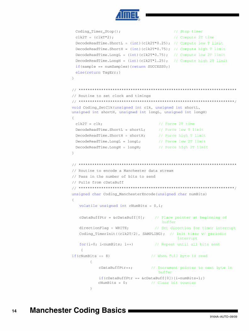
Coding_Timer_Stop(); // Stop timer
clk2T = (clkT*2); // Compute 2T time
DecodeReadTime.ShortL = (int)(clk2T*0.25); // Compute low T limit
DecodeReadTime.ShortH = (int)(clk2T*0.75); // Compute high T limit
DecodeReadTime.LongL = (int)(clk2T*0.75); // Compute low 2T limit
DecodeReadTime.LongH = (int)(clk2T*1.25); // Compute high 2T limit
if(sample == numSamples){return SUCCESS0;}
else{return TagErr;}
}
// **********************************************************************
// Routine to set clock and timings
// *********************************************************************/
void Coding_SetClk(unsigned int clk, unsigned int shortL, unsigned int shortH, unsigned int longL, unsigned int longH)
{
clk2T = clk; // Force 2T time
DecodeReadTime.ShortL = shortL; // Force low T limit
DecodeReadTime.ShortH = shortH; // Force high T limit
DecodeReadTime.LongL = longL; // Force low 2T limit
DecodeReadTime.LongH = longH; // Force high 2T limit
}
// **********************************************************************
// Routine to encode a Manchester data stream
// Pass in the number of bits to send
// Pulls from cDataBuff
// *********************************************************************/
unsigned char Coding_ManchesterEncode(unsigned char numBits)
{
volatile unsigned int cNumBits = 0,i;
cDataBuffPtr = &cDataBuff[0]; // Place pointer at beginning of buffer
directionFlag = WRITE; // Set direction for timer interrupt
Coding_TimerInit((clk2T/2), SAMPLING); // Init timer w/ periodic interrupt
for(i=0; i<numBits; i++) // Repeat until all bits sent
{
if(cNumBits == 8) // When full byte is read
{
cDataBuffPtr++; // Increment pointer to next byte in buffer
if(cDataBuffPtr == &cDataBuff[0]){i=numBits+1;}cNumBits = 0; // Clear bit counter
}
149164A–AUTO–09/09
Manchester Coding Basics

Manchester Coding Basics
if((*cDataBuffPtr & 0x80) == 0x80) // Check bit value, process logic one
{
cbi(IOPORT,DATAOUT); // Set I/O low
Coding_Timer_Poll(); // Catch next interrupt
sbi(IOPORT,DATAOUT); // Set I/O high
Coding_Timer_Poll(); // Catch next interrupt
}
else
{
sbi(IOPORT,DATAOUT); // Set I/O high
Coding_Timer_Poll(); // Catch next interrupt
cbi(IOPORT,DATAOUT); // Set I/O low
Coding_Timer_Poll(); // Catch next interrupt
}
*cDataBuffPtr = *cDataBuffPtr<<1; // Shift buffer to get next bit
cNumBits++; // Increment number of bits sent
}
return 0;
}
// **********************************************************************
// Routine to synchronize to manchester edge
// *********************************************************************/
unsigned char Coding_ManchesterSync(unsigned char maxSample)
{
unsigned char i=0;
unsigned int tmp;
unsigned char cOutput = SyncErr;
directionFlag = READ; // Set direction for timer interrupt
Coding_TimerInit(0x00, TIMING); // Init timer w/ edge-2-edge measurement
tmp = Coding_Timer_Poll(); // Wait for edge
while(i++ < maxSample) // Repeat until sample size is meet
{
tmp = Coding_Timer_Poll(); // Catch next edge time
if(tmp > UPPERTIMINGLMT){break;} // Check if edge time is useable
else if((tmp >= DecodeReadTime.LongL) && (tmp <= DecodeReadTime.LongH))
{
//2T time found, check starting logic value
if(tst(IOPIN,DATAIN) == 0){cOutput = SUCCESS0;}else{cOutput = SUCCESS1;}
break;
}
159164A–AUTO–09/09

}
return cOutput;
}
// **********************************************************************
// Routine to decode a Manchester bit
// Pass in the previous bit logic value
// *********************************************************************/
unsigned char Coding_ManchesterDecode(unsigned char cBit)
{
unsigned char cOutput = BitErr;
unsigned int tmp;
tmp = Coding_Timer_Poll(); // Catch next edge time
if(tmp < UPPERTIMINGLMT) // Check if edge time is useable
{
// Check edge time and determine next Logic value //
if((tmp > DecodeReadTime.LongL) && (tmp < DecodeReadTime.LongH))
{cOutput = cBit ^ 0x01;} // invert cBit for logical change
else if(tmp > DecodeReadTime.ShortL && tmp < DecodeReadTime.ShortH) // Next edge time is short
{
tmp = Coding_Timer_Poll();
if(tmp > DecodeReadTime.ShortL && tmp < DecodeReadTime.ShortH)
{cOutput = cBit;} // bit stays the same else{cOutput = BitErr;} // Un-paired short time
}
else {cOutput = BitErr;} // Edge time outside limits
}
return cOutput;
}
// **********************************************************************
// Routine to decode a BiPhase1 bit
// *********************************************************************/
unsigned char Coding_BiPhase1Decode(void)
{
unsigned char cOutput = BitErr;
unsigned int tmp;
tmp = Coding_Timer_Poll(); // Catch next edge time
if(tmp < UPPERTIMINGLMT) // Check if edge time is useable
{
// Check edge time and determine next Logic value //
if(tmp > DecodeReadTime.LongL && tmp < DecodeReadTime.LongH)
169164A–AUTO–09/09
Manchester Coding Basics

Manchester Coding Basics
{cOutput = 0;}
else if(tmp > DecodeReadTime.ShortL && tmp < DecodeReadTime.ShortH)
{
tmp = Coding_Timer_Poll();
if(tmp > DecodeReadTime.ShortL && tmp < DecodeReadTime.ShortH)
{cOutput = 1;}
else
{
cOutput = BitErr; // Un-paired short time between}
}
else {cOutput = BitErr;} // Edge time outside limits
}
return cOutput;
}
// **********************************************************************
// Read Routine Using the U2270
// **********************************************************************
void Coding_DSP(unsigned char Encoding)
{
unsigned char count=0, cLong=0, cShort=0;
unsigned char i, logicFlag, cNumBit=0, syncFlag=0;
unsigned char tmpData,j, bitVal=0;
volatile unsigned char *cDSPBuffPtr = &cDataBuff[0];
cDataBuffPtr = &cDataBuff[0]; // Place pointer at beginning of buffer
if((*cDSPBuffPtr & 0x80) == 0x80){logicFlag = 1;} // Initialize logic flag
else{logicFlag = 0;}
for(j=0; j<BUFFSIZE; j++) // Process entire buffer
{
tmpData = *cDSPBuffPtr++; // Pull out working byte
for(i=0; i<8; i++) // Process entire byte
{
if(!syncFlag)
{
if(logicFlag == 1 && (tmpData & 0x80) == 0x80){count++;}
else if(logicFlag == 0 && (tmpData & 0x80) == 0x00){count++;}
else
{
logicFlag = logicFlag^0x01; // Current flag inverted
if(count > 4)
179164A–AUTO–09/09

{
syncFlag=1; // 2T sync found
bitVal = logicFlag;
}
count=1; // Reset count
}
}
else
{
if(logicFlag == 1 && (tmpData & 0x80) == 0x80){count++;}
else if(logicFlag == 0 && (tmpData & 0x80) == 0x00){count++;}
else
{
// Check if count below threshold, inc short
if(count <=4){cShort++;}
else{cLong++;} // else inc long
count=1; // Reset count
logicFlag = logicFlag^0x01; // Current flag inverted
if(cLong == 1)
{
cLong = 0;
if(Encoding == MANCHESTER) // Decode Manchester
{bitVal = bitVal^0x01;}
else if(Encoding == BIPHASE1) // Decode BiPhase
{bitVal = 0;}
if(bitVal == 1)
{
*cDataBuffPtr = *cDataBuffPtr << 1;
*cDataBuffPtr = *cDataBuffPtr | 0x01;
}
else if(bitVal == 0)
{
*cDataBuffPtr = *cDataBuffPtr << 1;
}
cNumBit++;
}
else if(cShort == 2)
{
cShort = 0;
if(Encoding == MANCHESTER){;} else if(Encoding == BIPHASE1){bitVal = 1;}
if(bitVal == 1)
189164A–AUTO–09/09
Manchester Coding Basics

Manchester Coding Basics
{
*cDataBuffPtr = *cDataBuffPtr << 1;
*cDataBuffPtr = *cDataBuffPtr | 0x01;
}
else if(bitVal == 0)
{
*cDataBuffPtr = *cDataBuffPtr << 1;
}
cNumBit++;
}
if(cNumBit == 8) // When full byte is read
{
cDataBuffPtr++; // Inc ptr to next byte cNumBit = 0; // Clear bit counter
}
}
}
tmpData = tmpData << 1; // Shift working byte to next bit
}
}
}
// **********************************************************************
// Read Routine Using
// Pass in the number of Tag Type, data encoding, and type of synch.
// Pass in the number of bits being sent and the data buffer
// *********************************************************************/
unsigned char Coding_ReadData(unsigned char mode, unsigned int numBits, unsigned char startBit, unsigned char Encoding)
{
unsigned char cBit = 2;
volatile unsigned char cError = SUCCESS0;
unsigned char cQuit = 0;
unsigned int cNumBits = 0, cNumBytes = 0,i;
cBit = startBit;
if(mode == SAMPLING)
{
directionFlag = READ; // Set direction for timer interrupt
cDataBuff[BUFFSIZE-1] = 0x00; // Clear buffer end byte
Coding_TimerInit((clk2T/6), mode); // Init timer w/ periodic interrupt
do
199164A–AUTO–09/09

{
}
while(cDataBuff[BUFFSIZE-1] == 0x00);// Buffer end byte accessed
Coding_Timer_Stop(); // Stop Timer
Coding_DSP(Encoding); // Run DSP processing on samples.
}
else
{
cBit = Coding_ManchesterSync(100);
if(cBit == SUCCESS0 || cBit == SUCCESS1)
{
while(!cQuit)
{
for(i=0; i<(numBits*2)+10;i++)
{
if(cNumBits == 8) // When full byte is read
{
cDataBuffPtr++; // Increment pointer to next byte in buffer
cNumBits = 0; // Clear bit counter
cNumBytes++; // Increment byte counter
}
if(Encoding == MANCHESTER) // Decode the next bit
(Manchester)
{cBit = Coding_ManchesterDecode(cBit);}
else if(Encoding == BIPHASE1) // Decode the next bit (BiPhase)
{cBit = Coding_BiPhase1Decode();}
if(cBit == 1)
{
*cDataBuffPtr = *cDataBuffPtr << 1;
*cDataBuffPtr = *cDataBuffPtr | 0x01;
}
else if(cBit == 0)
{
*cDataBuffPtr = *cDataBuffPtr << 1;
}
else{break;}
cNumBits++; // Increment number of bits read
}
cQuit = 1;
}
if((cNumBits+(8*cNumBytes)) == (numBits*2)+10){cError = 0;}
else{cError = BitErr;}
209164A–AUTO–09/09
Manchester Coding Basics

Manchester Coding Basics
}
else{cError = SyncErr;}
Coding_Timer_Stop();
}
if(cError != 0){for(i=0; i < BUFFSIZE; i++){cDataBuff[i]=0x00;}} //Reset Buffer
return cError; // Return error code (zero = successfull)
}
// **********************************************************************
// * RFIDTimer Initialization of for Read Routine
// **********************************************************************
void Coding_TimerInit(unsigned int countVal, unsigned char mode)
{
CODINGTIMERMSK = 0x00; //Disable TC1 interrupts
cDataBuffPtr = &cDataBuff[0]; // Place pointer at beginning of buffer
OCR1A = countVal;
CODINGTIMERCNT = 0x00; //Load TC1 count value
if(mode == TIMING)
{
sbi(CODINGTIMERMSK,TICIE1); // Timer1 Input Capture & Interrupt Enable
sbi(CODINGTIMERMSK,TOIE1);
}
else{sbi(CODINGTIMERMSK,OCIE1A);} // Timer/Counter1 Output Compare A
CODINGTIMERFLR |= 0x27; //clear interrupt flags for TC1
CODINGTIMERCTRA = 0x00; //Normal mode
cbi(CODINGTIMERCTRB,ICES1); //Look for Falling Edge on ICP1
CODINGTIMERCTRB |= (1<<CS11); //prescale = clock source / 8 //exactly 1 us for every timer step
CODINGTIMERCTRC = 0x00; //Normal mode
}
219164A–AUTO–09/09

// **********************************************************************
// * Shutdown RFIDTimer
// **********************************************************************
void Coding_Timer_Stop(void)
{
CODINGTIMERMSK &= ~0x27; //Disable TC1 interrupts
CODINGTIMERCTRA = 0x00;
CODINGTIMERCTRB = 0x00; //No clock source / Timer Stopped
CODINGTIMERCTRC = 0x00;
CODINGTIMERFLR |= 0x27; //clear interrupt flags for TC1
}
// **********************************************************************
// * Read Edge Time
// **********************************************************************
unsigned int Coding_Timer_Poll(void)
{
asm("sei"); // Turn on global Interrupts
RdTime = 0; // Clear timing measurement
while(RdTime == 0){} // Wait for interrupt to generate measurement
return RdTime;
}
// **********************************************************************
// * RFIDTimer Output Compare Interrupt Routine
// **********************************************************************
ISR(CODINGTIMER_CMPA)
{
CODINGTIMERCNT = 0x0000; //Reset TC1 Count value
RdTime = 1; //Set Read Time = 1 (Timer Match)
if(directionFlag == READ) //Only process level sampling on Read
{
if(numSampleBits == 8) //Complete byte
{
numSampleBits = 0; //Reset bit counter
cDataBuffPtr++; //Inc buffer ptr
}
*cDataBuffPtr = *cDataBuffPtr<<1; //Shift in new bit
if(tst(IOPIN,DATAIN) == 1) //Check logic level
{
*cDataBuffPtr = *cDataBuffPtr|0x01; //Store one
}
229164A–AUTO–09/09
Manchester Coding Basics
Manchester Coding Basics
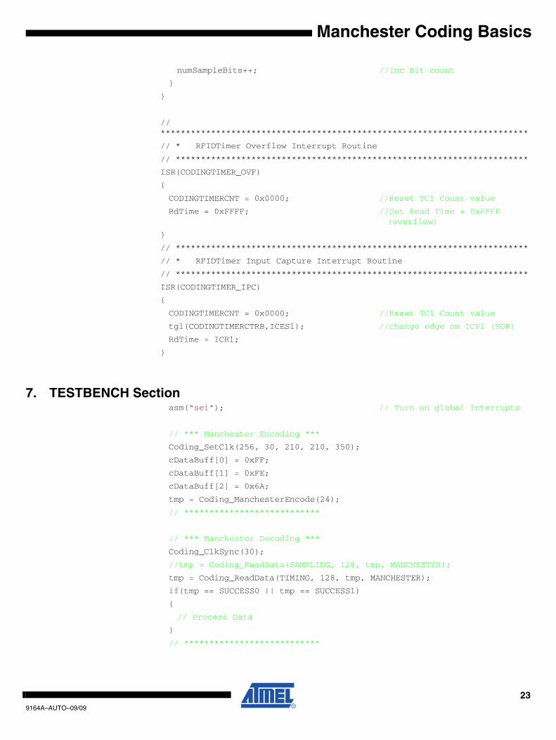
numSampleBits++; //Inc bit count
}
}
// *************************************************************************
// * RFIDTimer Overflow Interrupt Routine
// **********************************************************************
ISR(CODINGTIMER_OVF)
{
CODINGTIMERCNT = 0x0000; //Reset TC1 Count value
RdTime = 0xFFFF; //Set Read Time = 0xFFFF (overflow)
}
// **********************************************************************
// * RFIDTimer Input Capture Interrupt Routine
// **********************************************************************
ISR(CODINGTIMER_IPC)
{
CODINGTIMERCNT = 0x0000; //Reset TC1 Count value
tgl(CODINGTIMERCTRB,ICES1); //change edge on ICP1 (XOR)
RdTime = ICR1;
}
7. TESTBENCH Sectionasm("sei"); // Turn on global Interrupts
// *** Manchester Encoding ***
Coding_SetClk(256, 30, 210, 210, 350);
cDataBuff[0] = 0xFF;
cDataBuff[1] = 0xFE;
cDataBuff[2] = 0x6A;
tmp = Coding_ManchesterEncode(24);
// ***************************
// *** Manchester Decoding ***
Coding_ClkSync(30);
//tmp = Coding_ReadData(SAMPLING, 128, tmp, MANCHESTER);
tmp = Coding_ReadData(TIMING, 128, tmp, MANCHESTER);
if(tmp == SUCCESS0 || tmp == SUCCESS1)
{
// Process Data
}
// ***************************
239164A–AUTO–09/09
9164A–AUTO–09/09
Headquarters International
Atmel Corporation2325 Orchard ParkwaySan Jose, CA 95131USATel: 1(408) 441-0311Fax: 1(408) 487-2600
Atmel AsiaUnit 1-5 & 16, 19/FBEA Tower, Millennium City 5418 Kwun Tong RoadKwun Tong, KowloonHong KongTel: (852) 2245-6100Fax: (852) 2722-1369
Atmel EuropeLe Krebs8, Rue Jean-Pierre TimbaudBP 30978054 Saint-Quentin-en-Yvelines CedexFranceTel: (33) 1-30-60-70-00 Fax: (33) 1-30-60-71-11
Atmel Japan9F, Tonetsu Shinkawa Bldg.1-24-8 ShinkawaChuo-ku, Tokyo 104-0033JapanTel: (81) 3-3523-3551Fax: (81) 3-3523-7581
Product Contact
Web Sitewww.atmel.com
Technical [email protected]
Sales Contactwww.atmel.com/contacts
Literature Requestswww.atmel.com/literature
Disclaimer: The information in this document is provided in connection with Atmel products. No license, express or implied, by estoppel or otherwise, to anyintellectual property right is granted by this document or in connection with the sale of Atmel products. EXCEPT AS SET FORTH IN ATMEL’S TERMS AND CONDI-TIONS OF SALE LOCATED ON ATMEL’S WEB SITE, ATMEL ASSUMES NO LIABILITY WHATSOEVER AND DISCLAIMS ANY EXPRESS, IMPLIED OR STATUTORYWARRANTY RELATING TO ITS PRODUCTS INCLUDING, BUT NOT LIMITED TO, THE IMPLIED WARRANTY OF MERCHANTABILITY, FITNESS FOR A PARTICULARPURPOSE, OR NON-INFRINGEMENT. IN NO EVENT SHALL ATMEL BE LIABLE FOR ANY DIRECT, INDIRECT, CONSEQUENTIAL, PUNITIVE, SPECIAL OR INCIDEN-TAL DAMAGES (INCLUDING, WITHOUT LIMITATION, DAMAGES FOR LOSS OF PROFITS, BUSINESS INTERRUPTION, OR LOSS OF INFORMATION) ARISING OUT OFTHE USE OR INABILITY TO USE THIS DOCUMENT, EVEN IF ATMEL HAS BEEN ADVISED OF THE POSSIBILITY OF SUCH DAMAGES. Atmel makes norepresentations or warranties with respect to the accuracy or completeness of the contents of this document and reserves the right to make changes to specificationsand product descriptions at any time without notice. Atmel does not make any commitment to update the information contained herein. Unless specifically providedotherwise, Atmel products are not suitable for, and shall not be used in, automotive applications. Atmel’s products are not intended, authorized, or warranted for useas components in applications intended to support or sustain life.
© 2009 Atmel Corporation. All rights reserved. Atmel®, logo and combinations thereof, AVR® and others are registered trademarks or trade-marks of Atmel Corporation or its subsidiaries. Other terms and product names may be trademarks of others.
Related Documents


