Division / Business Unit: Enterprise Services Function: Track & Civil Document Type: Procedure © Australian Rail Track Corporation Limited (ARTC) Disclaimer This document has been prepared by ARTC for internal use and may not be relied on by any other party without ARTC’s prior written consent. Use of this document shall be subject to the terms of the relevant contract with ARTC. ARTC and its employees shall have no liability to unauthorised users of the information for any loss, damage, cost or expense incurred or arising by reason of an unauthorised user using or relying upon the information in this document, whether caused by error, negligence, omission or misrepresentation in this document. This document is uncontrolled when printed. Authorised users of this document should visit ARTC’s intranet or extranet (www.artc.com.au) to access the latest version of this document. Managing Track Stability ETM-06-08 Applicability ARTC Network Wide SMS Publication Requirement Internal / External Primary Source Consolidates ETM-06-06 and ETM-06-07. Document Status Version # Date Reviewed Prepared by Reviewed by Endorsed Approved 1.1 19 Dec 17 Standards Stakeholders Manager Standards A/General Manager Technical Standards 03/01/2018 Amendment Record Amendment Version # Date Reviewed Clause Description of Amendment 1.0 30 Jan 17 All Initial Issue 1.1 19 Dec 17 6.7, 10.5, 10.6, 12.6 Updated to form numbers

Welcome message from author
This document is posted to help you gain knowledge. Please leave a comment to let me know what you think about it! Share it to your friends and learn new things together.
Transcript
Division / Business Unit: Enterprise Services Function: Track & Civil Document Type: Procedure
© Australian Rail Track Corporation Limited (ARTC)
Disclaimer
This document has been prepared by ARTC for internal use and may not be relied on by any other party without ARTC’s prior written consent. Use of this document shall be subject to the terms of the relevant contract with ARTC.
ARTC and its employees shall have no liability to unauthorised users of the information for any loss, damage, cost or expense incurred or arising by reason of an unauthorised user using or relying upon the information in this document, whether caused by error, negligence, omission or misrepresentation in this document.
This document is uncontrolled when printed.
Authorised users of this document should visit ARTC’s intranet or extranet (www.artc.com.au) to access the latest version of this document.
Managing Track Stability ETM-06-08
Applicability
ARTC Network Wide
SMS
Publication Requirement
Internal / External
Primary Source
Consolidates ETM-06-06 and ETM-06-07.
Document Status
Version # Date Reviewed Prepared by Reviewed by Endorsed Approved
1.1 19 Dec 17 Standards Stakeholders Manager Standards
A/General Manager Technical Standards 03/01/2018
Amendment Record
Amendment Version #
Date Reviewed Clause Description of Amendment
1.0 30 Jan 17 All Initial Issue
1.1 19 Dec 17 6.7, 10.5, 10.6, 12.6
Updated to form numbers
Managing Track Stability
ETM-06-08
Table of Contents
This document is uncontrolled when printed. Version Number: 1.1 Date Reviewed: 19 Dec 17 Page 2 of 46
Table of Contents 1 Introduction ............................................................................................................................................. 5
1.1 Purpose ..................................................................................................................................... 5
1.2 Scope ........................................................................................................................................ 5
1.3 Document Owner ...................................................................................................................... 5
1.4 Reference Documents .............................................................................................................. 5
1.5 Australian Standard .................................................................................................................. 5
1.6 Definitions ................................................................................................................................. 6
2 Background ............................................................................................................................................. 8
2.1 Track Types .............................................................................................................................. 8
2.2 Maintenance of Track Stability .................................................................................................. 8
2.3 Buckling Force Management .................................................................................................... 8
2.4 Buckling Resistance Management............................................................................................ 9
2.5 Further Information ................................................................................................................... 9
3 Track Stability Management Plans ..................................................................................................... 10
3.1 Objective ................................................................................................................................. 10
3.2 General ................................................................................................................................... 10
3.3 Content .................................................................................................................................... 10
3.4 Preparation and Review Cycle ................................................................................................ 10
3.5 Relationship with Asset Management System ........................................................................ 11
3.6 Buckling Force ........................................................................................................................ 12
3.7 Buckling Resistance ................................................................................................................ 12
3.8 Special Locations .................................................................................................................... 12
4 Inspection & Assessment .................................................................................................................... 14
4.1 Patrol Inspections.................................................................................................................... 14
4.2 Scheduled General Inspections .............................................................................................. 14
4.3 Unscheduled General Inspections .......................................................................................... 14
4.4 Detailed Inspections – Concrete Sleepered Track ................................................................. 14
4.5 Detailed Inspections – Timber Sleepered Track ..................................................................... 15
5 General Inspections ............................................................................................................................. 16
5.1 Review of Special Locations ................................................................................................... 16
5.2 Impacts related to Buckling Force........................................................................................... 16
5.3 Impacts related to Buckling Resistance .................................................................................. 16

Managing Track Stability
ETM-06-08
Table of Contents
This document is uncontrolled when printed. Version Number: 1.1 Date Reviewed: 19 Dec 17 Page 3 of 46
5.4 Localised Initiators .................................................................................................................. 16
5.5 Assessment and Actions ......................................................................................................... 17
6 Stress Free Temperature Measurement ............................................................................................. 18
6.1 Locations for Measurement .................................................................................................... 18
6.2 Status of Schedule .................................................................................................................. 18
6.3 Frequency of measurement .................................................................................................... 18
6.4 Use in Conjunction with WTSA ............................................................................................... 19
6.5 Assessment and Actions – Concrete Sleepered Track .......................................................... 19
6.6 Assessment and Actions – Timber Sleepered Track .............................................................. 19
6.7 Records ................................................................................................................................... 20
7 Rail Creep Measurement ..................................................................................................................... 21
7.1 General ................................................................................................................................... 21
7.2 Assessment and Actions – Concrete Sleepered Track .......................................................... 21
7.3 Assessment and Actions – Timber Sleepered Track .............................................................. 22
8 Curve Alignment Measurement .......................................................................................................... 23
8.1 General ................................................................................................................................... 23
8.2 Assessment and Actions ......................................................................................................... 23
9 High Temperature Work Restrictions ................................................................................................. 25
9.1 General ................................................................................................................................... 25
9.2 Local Work Restrictions .......................................................................................................... 25
9.3 Standard Work Restrictions .................................................................................................... 26
9.4 Track Awaiting Stressing ........................................................................................................ 26
10 High Temperature Speed Restrictions ............................................................................................... 27
10.1 General ................................................................................................................................... 27
10.2 Concrete Sleepered Track ...................................................................................................... 27
10.3 Timber Sleepered Track ......................................................................................................... 27
10.4 Obtaining Temperature Forecasts .......................................................................................... 28
10.5 Application of High Temperature Speed Restrictions ............................................................. 28
10.6 Early Removal of High Temperature Speed Restriction ......................................................... 28
10.7 Alternative Speed Restrictions ................................................................................................ 28
10.8 Speed Restrictions Following Track Disturbance ................................................................... 29
10.9 Inspection Prior to Removal .................................................................................................... 29

Managing Track Stability
ETM-06-08
Table of Contents
This document is uncontrolled when printed. Version Number: 1.1 Date Reviewed: 19 Dec 17 Page 4 of 46
11 High Temperature Track Patrol Inspections ...................................................................................... 30
11.1 Objectives ............................................................................................................................... 30
11.2 Requirements .......................................................................................................................... 30
11.3 Concrete Sleepered Track ...................................................................................................... 30
11.4 Timber Sleepered Track ......................................................................................................... 30
11.5 Assessment and Actions ......................................................................................................... 31
11.6 Deferral of Inspections ............................................................................................................ 31
12 Track Buckles ....................................................................................................................................... 32
12.1 General ................................................................................................................................... 32
12.2 Classification ........................................................................................................................... 32
12.3 Causes and Remedies ............................................................................................................ 32
12.4 Correction of Buckles .............................................................................................................. 33
12.5 Stress Free Temperature ........................................................................................................ 33
12.6 Investigation and Reporting .................................................................................................... 34
12.7 Follow-Up Actions ................................................................................................................... 34
Attachments
Attachment A: Outline Track Stability Management Plan .......................................................................... 36
Attachment B: Standard High Temperature Work Restrictions ................................................................ 40
Attachment C: Guidelines for the Correction of Buckles ........................................................................... 43
Attachment D: Guidelines for Investigation of Buckles ............................................................................. 45

Managing Track Stability
ETM-06-08
Introduction
© Australian Rail Track Corporation Limited (ARTC)
Disclaimer
This document has been prepared by ARTC for internal use and may not be relied on by any other party without ARTC’s prior written consent. Use of this document shall be subject to the terms of the relevant contract with ARTC.
ARTC and its employees shall have no liability to unauthorised users of the information for any loss, damage, cost or expense incurred or arising by reason of an unauthorised user using or relying upon the information in this document, whether caused by error, negligence, omission or misrepresentation in this document.
This document is uncontrolled when printed.
Authorised users of this document should visit ARTC’s intranet or extranet (www.artc.com.au) to access the latest version of this document.
1 Introduction
1.1 Purpose The purpose of this procedure is to specify and describe requirements for managing track lateral stability.
1.2 Scope This procedure specifies requirements for:
• Preparation and review of Track Stability Management Plans (TSMPs)
• Inspection and assessment of the stability of concrete, timber, steel and composite sleepered welded track
• Managing track stability during high temperatures
• Preventing, investigating, repairing and reporting track buckles.
The requirements are applicable to CWR and LWR in main lines.
1.3 Document Owner The Manager Standards is the document owner and is the initial point of contact for all queries relating to this procedure.
1.4 Reference Documents This procedure is to be read in conjunction with the following documents:
• ARTC Track & Civil Code of Practice Section 2 – Sleepers and Fastenings
• ARTC Track & Civil Code of Practice Section 4 – Ballast
• ARTC Track & Civil Code of Practice Section 6 – Track Lateral Stability
• EGP-10-01 Asset Maintenance Works Management
• ETE-00-03 Civil Technical Maintenance Plan
• ETI-11-01 Trackside Monuments for Track Alignment
• ETM-06-09 Welded Track Stability Analysis
• ETN-06-01 Track Stability Handbook .
1.5 Australian Standard This Procedure has been checked against and conforms to all mandatory sections of AS 7643 Infrastructure - Track Stability.
Managing Track Stability
ETM-06-08
Introduction
This document is uncontrolled when printed. Version Number: 1.1 Date Reviewed: 19 Dec 17 Page 6 of 46
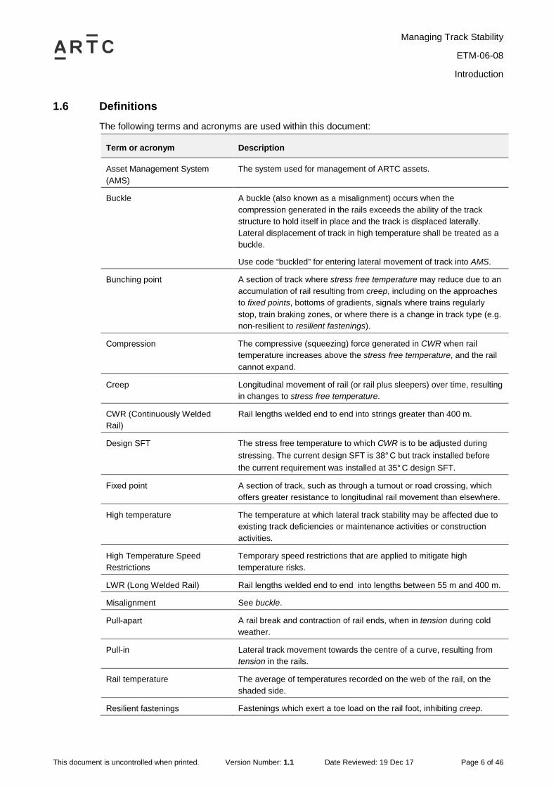
1.6 Definitions The following terms and acronyms are used within this document:
Term or acronym Description
Asset Management System (AMS)
The system used for management of ARTC assets.
Buckle A buckle (also known as a misalignment) occurs when the compression generated in the rails exceeds the ability of the track structure to hold itself in place and the track is displaced laterally. Lateral displacement of track in high temperature shall be treated as a buckle.
Use code “buckled” for entering lateral movement of track into AMS.
Bunching point A section of track where stress free temperature may reduce due to an accumulation of rail resulting from creep, including on the approaches to fixed points, bottoms of gradients, signals where trains regularly stop, train braking zones, or where there is a change in track type (e.g. non-resilient to resilient fastenings).
Compression The compressive (squeezing) force generated in CWR when rail temperature increases above the stress free temperature, and the rail cannot expand.
Creep Longitudinal movement of rail (or rail plus sleepers) over time, resulting in changes to stress free temperature.
CWR (Continuously Welded Rail)
Rail lengths welded end to end into strings greater than 400 m.
Design SFT The stress free temperature to which CWR is to be adjusted during stressing. The current design SFT is 38°C but track installed before the current requirement was installed at 35°C design SFT.
Fixed point A section of track, such as through a turnout or road crossing, which offers greater resistance to longitudinal rail movement than elsewhere.
High temperature The temperature at which lateral track stability may be affected due to existing track deficiencies or maintenance activities or construction activities.
High Temperature Speed Restrictions
Temporary speed restrictions that are applied to mitigate high temperature risks.
LWR (Long Welded Rail) Rail lengths welded end to end into lengths between 55 m and 400 m.
Misalignment See buckle.
Pull-apart A rail break and contraction of rail ends, when in tension during cold weather.
Pull-in Lateral track movement towards the centre of a curve, resulting from tension in the rails.
Rail temperature The average of temperatures recorded on the web of the rail, on the shaded side.
Resilient fastenings Fastenings which exert a toe load on the rail foot, inhibiting creep.
Managing Track Stability
ETM-06-08
Introduction
This document is uncontrolled when printed. Version Number: 1.1 Date Reviewed: 19 Dec 17 Page 7 of 46
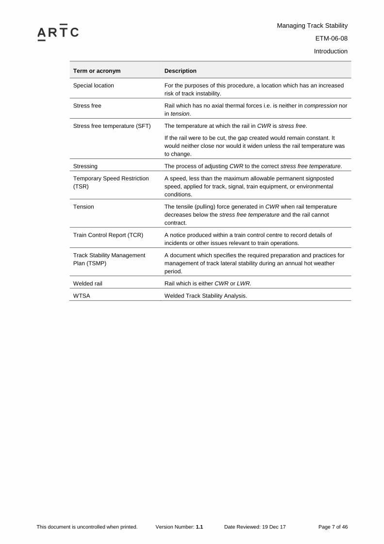
Term or acronym Description
Special location For the purposes of this procedure, a location which has an increased risk of track instability.
Stress free Rail which has no axial thermal forces i.e. is neither in compression nor in tension.
Stress free temperature (SFT) The temperature at which the rail in CWR is stress free.
If the rail were to be cut, the gap created would remain constant. It would neither close nor would it widen unless the rail temperature was to change.
Stressing The process of adjusting CWR to the correct stress free temperature.
Temporary Speed Restriction (TSR)
A speed, less than the maximum allowable permanent signposted speed, applied for track, signal, train equipment, or environmental conditions.
Tension The tensile (pulling) force generated in CWR when rail temperature decreases below the stress free temperature and the rail cannot contract.
Train Control Report (TCR) A notice produced within a train control centre to record details of incidents or other issues relevant to train operations.
Track Stability Management Plan (TSMP)
A document which specifies the required preparation and practices for management of track lateral stability during an annual hot weather period.
Welded rail Rail which is either CWR or LWR.
WTSA Welded Track Stability Analysis.
Managing Track Stability
ETM-06-08
Background
This document is uncontrolled when printed. Version Number: 1.1 Date Reviewed: 19 Dec 17 Page 8 of 46
2 Background
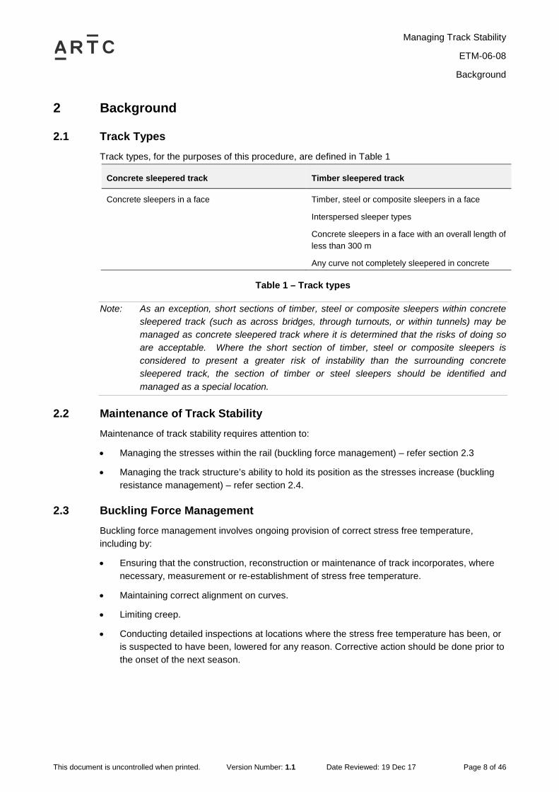
2.1 Track Types Track types, for the purposes of this procedure, are defined in Table 1
Concrete sleepered track Timber sleepered track
Concrete sleepers in a face Timber, steel or composite sleepers in a face
Interspersed sleeper types
Concrete sleepers in a face with an overall length of less than 300 m
Any curve not completely sleepered in concrete
Table 1 – Track types
Note: As an exception, short sections of timber, steel or composite sleepers within concrete sleepered track (such as across bridges, through turnouts, or within tunnels) may be managed as concrete sleepered track where it is determined that the risks of doing so are acceptable. Where the short section of timber, steel or composite sleepers is considered to present a greater risk of instability than the surrounding concrete sleepered track, the section of timber or steel sleepers should be identified and managed as a special location.
2.2 Maintenance of Track Stability Maintenance of track stability requires attention to:
• Managing the stresses within the rail (buckling force management) – refer section 2.3
• Managing the track structure’s ability to hold its position as the stresses increase (buckling resistance management) – refer section 2.4.
2.3 Buckling Force Management Buckling force management involves ongoing provision of correct stress free temperature, including by:
• Ensuring that the construction, reconstruction or maintenance of track incorporates, where necessary, measurement or re-establishment of stress free temperature.
• Maintaining correct alignment on curves.
• Limiting creep.
• Conducting detailed inspections at locations where the stress free temperature has been, or is suspected to have been, lowered for any reason. Corrective action should be done prior to the onset of the next season.

Managing Track Stability
ETM-06-08
Background
This document is uncontrolled when printed. Version Number: 1.1 Date Reviewed: 19 Dec 17 Page 9 of 46
2.4 Buckling Resistance Management Buckling resistance management involves ongoing provision of a track structure able to resist buckling forces, including by:
• Ensuring that failures or poor condition of components which impact on lateral resistance are identified and assessed prior to the onset of the high temperature season, and rectified or protected as required in Standards.
• Ensuring that locations with high vulnerability to lateral resistance issues are identified and provided with appropriate attention prior to the onset of the high temperature season.
• Having a plan specifically targeted to the maintenance of track lateral resistance, which is robust enough to cover general maintenance practices to be undertaken during the high temperature season, as well as targeting situations specific to an individual location or defined event.
Maintenance of track lateral resistance requires attention to managing the track structure’s ability to hold its position as thermal stresses in the rail increase. Component condition is assessed in accordance with the criteria in the Track & Civil Code of Practice, and the vulnerable locations identified by review of buckle history and by the general stability inspection.
2.5 Further Information For further information on track stability, refer ETN-06-01 Track Stability Hand Book.

Managing Track Stability
ETM-06-08
Track Stability Management Plans
This document is uncontrolled when printed. Version Number: 1.1 Date Reviewed: 19 Dec 17 Page 10 of 46
3 Track Stability Management Plans
3.1 Objective The objective of a TSMP is to bring together in a concise plan all the activities associated with:
• Inspecting and managing the track to ensure lateral stability, particularly preparations prior to the annual hot weather period.
• Ensuring track stability during hot weather and, where applicable, during extremely cold weather.
3.2 General A separate TSMP must be in place for each section of track. Each plan is to specify the local requirements for managing track lateral stability.
Each plan is to be;
• Operative continuously throughout the year
• Approved and reissued annually.
(Refer section 3.4.)
3.3 Content An outline of a typical TSMP is given in Attachment A: Outline Track Stability Management Plan. Principal features include;
• Requirements for managing buckling force – refer section 3.6
• Requirements for managing buckling resistance – refer section 3.7
• High temperature work restrictions – refer section 9
• High temperature speed restrictions – refer section 10
• High Temperature inspections – refer section 11
• Special locations register (as an attachment) – refer section 3.8
3.4 Preparation and Review Cycle Following the end of the high temperature season each year (typically in March/April), the TSMP is to be reviewed, particularly to;
• Assess track performance during the hot weather
• Determine any precautions required during forthcoming colder weather
• Identify actions needed prior to the next high temperature season
• Re-evaluate trigger temperature(s) at which speed restrictions are to be imposed and unscheduled track lateral stability patrol inspections undertaken

Managing Track Stability
ETM-06-08
Track Stability Management Plans
This document is uncontrolled when printed. Version Number: 1.1 Date Reviewed: 19 Dec 17 Page 11 of 46
Following this review, the TSMP is to be updated, approved, and reissued no later than the end of September.
The TSMP is to be further reviewed as follows;
• Prior to the onset of hot weather (typically by the end of October), particularly to assess the adequacy of hot weather preparatory actions
• Monthly during hot weather
• At other times when necessary
It is expected that only in exceptional circumstances will these further TSMP reviews require wholesale amendment of the annual plan. Reviews normally may result in:
• Additional tasks being entered into AMS, or
• Changes to the special locations register which is attached to the TSMP (refer section 3.8).
The preparation and review cycle is summarised in Figure 1.
Figure 1 – TSMP preparation and review cycle
Note: On LWR, preparations for hot weather are implemented when temperatures are favourable, typically in September/October.
3.5 Relationship with Asset Management System To the greatest extent possible, inspections, maintenance tasks, and emerging defects requiring surveillance, as identified in the TSMP, are to managed within AMS – refer EGP-10-01 Asset Maintenance Works Management.
Jan Feb
Mar
Dec
Nov
Oct
JunJly
Aug
Sep
May
Apr
During colder weather Implement preparations
for hot weather.
Prior to hot weather Review TSMP.
March/April Assess performance during hot weather.
Identify actions during colder weather. Update TSMP.
November – March/April Implement hot weather restrictions. Implement hot weather inspections.
Review TSMP monthly.
By end September Track stability
general inspection (ETE-00-03) to
review preparedness for hot weather. Approve TSMP.
Managing Track Stability
ETM-06-08
Track Stability Management Plans
This document is uncontrolled when printed. Version Number: 1.1 Date Reviewed: 19 Dec 17 Page 12 of 46
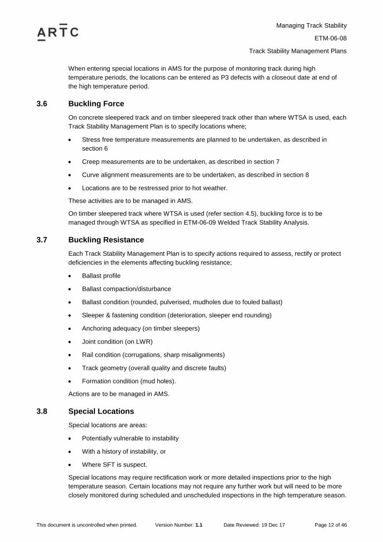
When entering special locations in AMS for the purpose of monitoring track during high temperature periods, the locations can be entered as P3 defects with a closeout date at end of the high temperature period.
3.6 Buckling Force On concrete sleepered track and on timber sleepered track other than where WTSA is used, each Track Stability Management Plan is to specify locations where;
• Stress free temperature measurements are planned to be undertaken, as described in section 6
• Creep measurements are to be undertaken, as described in section 7
• Curve alignment measurements are to be undertaken, as described in section 8
• Locations are to be restressed prior to hot weather.
These activities are to be managed in AMS.
On timber sleepered track where WTSA is used (refer section 4.5), buckling force is to be managed through WTSA as specified in ETM-06-09 Welded Track Stability Analysis.
3.7 Buckling Resistance Each Track Stability Management Plan is to specify actions required to assess, rectify or protect deficiencies in the elements affecting buckling resistance;
• Ballast profile
• Ballast compaction/disturbance
• Ballast condition (rounded, pulverised, mudholes due to fouled ballast)
• Sleeper & fastening condition (deterioration, sleeper end rounding)
• Anchoring adequacy (on timber sleepers)
• Joint condition (on LWR)
• Rail condition (corrugations, sharp misalignments)
• Track geometry (overall quality and discrete faults)
• Formation condition (mud holes).
Actions are to be managed in AMS.
3.8 Special Locations Special locations are areas:
• Potentially vulnerable to instability
• With a history of instability, or
• Where SFT is suspect.
Special locations may require rectification work or more detailed inspections prior to the high temperature season. Certain locations may not require any further work but will need to be more closely monitored during scheduled and unscheduled inspections in the high temperature season.
Managing Track Stability
ETM-06-08
Track Stability Management Plans
This document is uncontrolled when printed. Version Number: 1.1 Date Reviewed: 19 Dec 17 Page 13 of 46
Track stability special locations typically may include:
• Curves of radius 400 m and below
• Track sections with a history of lateral instability or pull-apart failures
• Bunching points
• Areas with a non-conforming ballast profile
• Anchored track, where anchors are missing, to an irregular pattern, or not hard up against the sleepers
• Areas recently affected by track disturbance (e.g. tamping)
• Locations where a review of stressing records for welds undertaken since the last TSMP was prepared indicate that SFT is suspect
• Sites with localised initiators (e.g. mud holes).
Track stability special locations typically must include:
• Sites of those buckles over the previous 3 high temperature seasons where a residual risk of further instability is considered possible
• Sites with multiple concurrent initiator defects
• Outstanding maintenance tasks recorded in AMS which potentially affect track stability to a significant extent, necessitating closer than normal monitoring.
Sites required to be monitored as special locations shall be determined and are to be recorded in AMS and a register attached to the Track Stability Management Plan.
Consideration will need to be given to imposing speed restrictions at special locations upon the onset of hot weather, to mitigate the risks posed to the lateral stability of the track if the required rectification works have yet to be completed or, by their nature, cannot be eliminated.
Special locations will be subject to ongoing change, so must be reassessed in conjunction with each review of the Track Stability Management Plan.
Managing Track Stability
ETM-06-08
Inspection & Assessment
This document is uncontrolled when printed. Version Number: 1.1 Date Reviewed: 19 Dec 17 Page 14 of 46
4 Inspection & Assessment
4.1 Patrol Inspections Requirements relating to track stability during scheduled patrol inspections are specified in ARTC Track & Civil Code of Practice Section 6 – Track Lateral Stability.
4.2 Scheduled General Inspections A scheduled general inspection of track stability in accordance with the ARTC Track & Civil Code of Practice Section 6 - Track Lateral Stability, is to be carried out as specified in ETE-00-03 Civil Technical Maintenance Plan.
Note: The scheduled general inspection of track stability should be carried out as part of the preparation of the annual Track Stability Management Plan.
The inspection should primarily be to review preparedness for hot weather, rather than for identifying and planning the work to be done.
Requirements relating to track stability during scheduled general inspections are specified in section 5, and in ARTC Code of Practice Section 6 – Track Lateral Stability.
4.3 Unscheduled General Inspections Unscheduled general inspections may be performed at any time of the year. The objectives of unscheduled general inspections are to:
• Keep a lookout for defects and conditions that may affect, or indicate problems with, track lateral stability
• Detect early indications of instability
• Allow closer assessment of any condition that has been identified during track patrol or TCR that may impact on lateral stability.
Requirements relating to track stability during unscheduled general inspections are specified in section 5, and in ARTC Code of Practice Section 6 – Track Lateral Stability.
4.4 Detailed Inspections – Concrete Sleepered Track On concrete sleepered track, detailed inspections may include:
• Stress free temperature measurements, as detailed in section 6
• Rail creep measurements, as detailed in section 7
• Curve alignment measurements, as detailed in section 8.

Managing Track Stability
ETM-06-08
Inspection & Assessment
This document is uncontrolled when printed. Version Number: 1.1 Date Reviewed: 19 Dec 17 Page 15 of 46
4.5 Detailed Inspections – Timber Sleepered Track
On timber sleepered track, detailed inspections of track stability must be carried out as specified in *Where WTSA has traditionally been used and demonstrated to be effective in preventing buckles then it should continue to be used.
Table 2.
Maximum line speed Detailed inspection
Above 60 km/h WTSA* – refer ETM-06-09 Welded Track Stability Analysis, or
Joint Gap Measurement (LWR only) – refer below, or
Rail creep measurement (CWR only) – refer section 7, or
Stress free temperature measurement (CWR only) – refer section 6, or
A combination of creep measurement and stress free temperature measurement (CWR only).
60 km/h or less Detailed inspection not mandatory. Process to be shown in TSMP.
*Where WTSA has traditionally been used and demonstrated to be effective in preventing buckles then it should continue to be used.
Table 2 – Detailed inspections of timber sleepered track
Creep or joint gap assessment (not as part of WTSA) is an optional method of detailed inspection on timber sleepered LWR tracks with a maximum line speed of 80 km/h or less.
Joint gaps are to be assessed visually and measured. The annual schedule of intended measurements is to be included in the Track Stability Management Plan.
Rails with irregular joint gaps or frozen joints should be adjusted to standard.
Further information on how to measure and assess LWR joint gaps is given in ETM-06-09 Welded Track Stability Analysis.
Managing Track Stability
ETM-06-08
General Inspections
This document is uncontrolled when printed. Version Number: 1.1 Date Reviewed: 19 Dec 17 Page 16 of 46
5 General Inspections
5.1 Review of Special Locations Prior to performing a scheduled general inspection, the latest list of special locations is to be obtained and reviewed.
Consideration is to be given as to whether the impact on the lateral stability posed at these locations is due to buckling force or buckling resistance issues. This will impact on the way the location is to be assessed, and the actions that may be recommended as a result.
5.2 Impacts related to Buckling Force Locations where the rail has been stressed due to track construction, reconditioning or re-railing etc. and are still awaiting stress free temperature checks, will impact on buckling force management and should be scheduled for detailed inspection of stress free temperature. Appropriate restrictions must be implemented on works requiring stressing.
Locations where it has been identified that curves have pulled in, or where there are indications that longitudinal creep will impact on buckling force management, should be scheduled for detailed inspection of stress free temperature, curve alignment, or creep.
5.3 Impacts related to Buckling Resistance Locations where the ballast profile is non-compliant with the nominal ballast profile dimensions specified in ARTC Code of Practice Section 4 - Ballast will impact on buckling resistance management and should be scheduled for rectification.
5.4 Localised Initiators All special locations are to be assessed during the scheduled inspections to determine if there are additional conditions present that will increase the locations vulnerability to instability.
Attention is to be paid to potential localised initiators, such as:
• Poor rail or weld alignment arising from incorrect crowing, rail end misalignment, poor rail profile matching, straight closures in curves, track alignment (including gauge), and glued insulated joints
• Rail surface and track geometry defects including poor top, twists, dipped welds, wheel burns or corrugations, and pumping sleepers
• Rail bunching at fixed points, e.g. bridges, turnouts or level crossings
• Rail bunching due to trains stopping at signals, or to changes in grade
• Loose or failed fastening assemblies with reduced toe load, causing rail creep
• Local disturbances due to under-track crossings, bridges or culverts.
Particular attention must be paid to those locations on curves less than 400 m radius, as tight radius curves have higher buckling risk.

Managing Track Stability
ETM-06-08
General Inspections
This document is uncontrolled when printed. Version Number: 1.1 Date Reviewed: 19 Dec 17 Page 17 of 46
5.5 Assessment and Actions Where there is any track where the stability is suspected of being deficient:
• Initiate work programmes to eliminate the fault(s)
• Prioritise rectification tasks
• Record requirements in AMS
• Update the special locations register
• Impose appropriate speed restrictions.
Sections of track with ballast deficiencies must be assessed and actioned in accordance with ARTC Code of Practice Section 4 – Ballast. In prioritising rectification, consideration must be given to locations where:
• Track lateral strength is reduced for other reasons (refer ARTC Code of Practice Section 6 – Track Lateral Stability), or
• There are concurrent localised initiators.
Locations where rail defects have been removed or short rail installed, and the balance of steel has been changed, must be listed as defects in the AMS and the location adjusted. This work must be programmed before the onset of any warmer weather.

Managing Track Stability
ETM-06-08
Stress Free Temperature Measurement
This document is uncontrolled when printed. Version Number: 1.1 Date Reviewed: 19 Dec 17 Page 18 of 46
6 Stress Free Temperature Measurement
6.1 Locations for Measurement Locations where SFT may be measured include:
• Outstanding locations where SFT is required to be measured following stressing
• In the vicinity of bunching points
• Where there have been indications of lateral instability or rail creep
• Locations where broken rails have occurred since the previous inspection
• Locations where rail defects have been removed or short rail installed, and the balance of steel has been changed, or there have been multiple repairs in the same vicinity
• As an optional method of detailed inspection on timber sleepered CWR tracks with a maximum line speed above 60km/h
• As part of the response to creep variations – refer section 7
• At a random selection of locations
• Other locations or where compliant SFT is questionable.
The location and schedule for measuring SFT shall be defined in the TSMP (it is not necessary to check every site every year).
Initial screening may be by rail creep measurement - refer section 7.
Note: It is not necessary that repeat SFT measurements be in exactly the same location, or that measurements be compared to previous readings.
Stress free temperature measurements should not be carried out on LWR track, as the results are likely to be unreliable.
6.2 Status of Schedule Other than in response to suspected defects (e.g. creep variations), or where required to be measured following stressing, the schedule of planned testing presented in the TSMP should be managed as an objective rather than a mandatory requirement. Achievement of all planned testing will depend on various factors, such as the need to “chase” non-conformances with further testing in the area, or the timing of the onset of hot weather.
The site of a planned test which is not able to be completed prior to the onset of hot weather, and where SFT is suspect, should be treated as a special location.
6.3 Frequency of measurement Where stress free temperature is to be measured periodically (e.g. at bunching points), the recommended interval for measurement is 4 years. The specific interval for each site should be determined during the preparation of the annual TSMP.

Managing Track Stability
ETM-06-08
Stress Free Temperature Measurement
This document is uncontrolled when printed. Version Number: 1.1 Date Reviewed: 19 Dec 17 Page 19 of 46
6.4 Use in Conjunction with WTSA For use of SFT measurements on timber sleepered CWR track as part of WTSA, refer ETM-06-09 Welded Track Stability Analysis.
6.5 Assessment and Actions – Concrete Sleepered Track Permissible SFT tolerance on newly stressed rail is ±5oC of the design SFT.
Responses to SFT measurements at all other locations are given in Table 3. Any identified non-conformances should be entered into AMS for attention.
Measured SFT Response
SFT 28°C – 24°C (average of both rails)
Increase monitoring or stress, with priority having regard to other contributing factors.
SFT 23°C or less (average of both rails)
Stress, with priority having regard to other contributing factors. Treat as special location until rectified.
SFT 48°C or more (on either rail) Stress.
Table 3 – Responses to stress free temperature variations, concrete sleepered track
6.6 Assessment and Actions – Timber Sleepered Track Permissible SFT tolerance on newly stressed rail is ±5oC of the design SFT.
Responses to SFT measurements at all other locations are given in Table 4. Any identified non-conformances should be entered into AMS for attention.
Variation from Design SFT Response
SFT 30°C – 27°C (average of both rails)
Increase monitoring or stress, with priority having regard to other contributing factors.
SFT 26°C or less (average of both rails)
Stress, with priority having regard to other contributing factors. Treat as special location until rectified.
SFT 43°C or more (on either rail) Stress.
Table 4 – Responses to stress free temperature variations, timber sleepered track

Managing Track Stability
ETM-06-08
Stress Free Temperature Measurement
This document is uncontrolled when printed. Version Number: 1.1 Date Reviewed: 19 Dec 17 Page 20 of 46
6.7 Records Records of all SFT measurements are to be maintained, using a form applicable to the measuring device used (e.g. ETM0608F-03 Stress Free Temperature Test and Record Sheet).
The minimum information recorded should include:
• Device used
• Location: line, kilometrage (including GPS if applicable)
• Track (if applicable), rail (left/right or up/down)
• Date and time of test
• Rail temperature
• Measured SFT
• Required response (from table)
• Operator's name and signature.

Managing Track Stability
ETM-06-08
Rail Creep Measurement
This document is uncontrolled when printed. Version Number: 1.1 Date Reviewed: 19 Dec 17 Page 21 of 46
7 Rail Creep Measurement
7.1 General On concrete sleepered tracks, instead of SFT measurements, an optional method of obtaining an initial indication of potential SFT non-conformance is by measurement of rail creep.
On timber sleepered CWR tracks with a line speed above of 60 km/h, creep assessment (not as part of WTSA) is an optional method of detailed inspection.
On all tracks where creep pegs are provided and are known to have been reset against correctly stressed rail, creep measurements must be made annually.
Creep measurements assess buckling force by providing an indirect indication of potential rail stress non-conformance. (Buckling resistance is assessed during the general inspection.)
Creep may be assessed by:
• Measurement of rail movement past fixed monuments provided in accordance with ARTC Code of Practice Section 6 – Track Lateral Stability
• GPS based survey of rail movement (of sufficient accuracy).
Creep should be measured on both rails, and the results averaged.
The annual schedule of intended measurements is to be included in the TSMP, with any identified creep non-conformances entered into AMS for attention.
Note: SFT measurements are preferable to rail creep measurements. Creep measurements are only valid if the measuring datum is established when SFT is known to be correct.
Creep measurements should be assessed to determine where bunching is occurring, i.e. where creep into a section of track is not matched by corresponding creep out of the section.
7.2 Assessment and Actions – Concrete Sleepered Track Responses to rail creep variations are given in Table 5.
Rail creep Response
>30 – 50 mm Measure SFT, typically 100 m – 300 m on the side of the creep monument gaining rail, or in the vicinity of a bunching point, otherwise monitor location by remeasuring creep.
>50 mm Measure SFT, typically 100 m – 300 m on the side of the creep monument gaining rail, or in the vicinity of a bunching point, otherwise stress. Treat as a special location until actioned.
Table 5 – Responses to creep variations on concrete sleepered track
Managing Track Stability
ETM-06-08
Rail Creep Measurement
This document is uncontrolled when printed. Version Number: 1.1 Date Reviewed: 19 Dec 17 Page 22 of 46
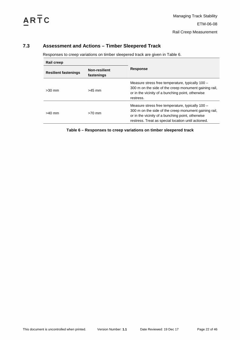
7.3 Assessment and Actions – Timber Sleepered Track Responses to creep variations on timber sleepered track are given in Table 6.
Rail creep
Response Resilient fastenings Non-resilient
fastenings
>30 mm >45 mm
Measure stress free temperature, typically 100 – 300 m on the side of the creep monument gaining rail, or in the vicinity of a bunching point, otherwise restress.
>40 mm >70 mm
Measure stress free temperature, typically 100 – 300 m on the side of the creep monument gaining rail, or in the vicinity of a bunching point, otherwise restress. Treat as special location until actioned.
Table 6 – Responses to creep variations on timber sleepered track

Managing Track Stability
ETM-06-08
Curve Alignment Measurement
This document is uncontrolled when printed. Version Number: 1.1 Date Reviewed: 19 Dec 17 Page 23 of 46
8 Curve Alignment Measurement
8.1 General Curves where alignment monuments are provided, and the monuments are known to have been offset from correctly aligned track and correctly stressed rail, should be measured annually.
Elsewhere, curve alignment monuments should be provided and measured annually where:
• The curve has a history of, or is at risk of, pulling in or misaligning
• Alignment measurements are required for other reasons (e.g. track centre clearance checks).
The annual schedule of curves to be measured is to be included in the TSMP and any identified non-conformances entered into AMS for attention.
Note: SFT measurements are preferable to curve alignment measurements. SFT variations derived from curve alignment measurements are only valid if the monuments were established or reset when both alignment and SFT were known to be correct.
8.2 Assessment and Actions 1 Calculate the average pull-in from all measurements taken on the curve.
2 From the following table, determine if the corresponding reduction in SFT has reached an intervention level.
3 Respond in accordance with Table 7.
Curve radius (m) Pull-in for 10°C reduction in SFT Pull-in for 15°C reduction in SFT
200 25 mm 35 mm
250 30 mm 45 mm
300 35 mm 55 mm
350 45 mm 65 mm
400 50 mm 70 mm
500 55 mm 85 mm
600 65 mm 100 mm
Response Increase monitoring or realign curve, with priority having regard to other contributing factors.
Realign curve, with priority having regard to other contributing factors. Treat as special location until rectified.
Table 7 – Responses to curve pull-in
Managing Track Stability
ETM-06-08
Curve Alignment Measurement
This document is uncontrolled when printed. Version Number: 1.1 Date Reviewed: 19 Dec 17 Page 24 of 46
Note: Correct alignment, smooth line, and an absence of misalignment triggers are critical for maintaining stability on sharp curves, particularly where the radius is less than 300 m. On larger radius curves, the greater risk is likely to be from short, discrete line defects acting as misalignment triggers.

Managing Track Stability
ETM-06-08
High Temperature Work Restrictions
This document is uncontrolled when printed. Version Number: 1.1 Date Reviewed: 19 Dec 17 Page 25 of 46
9 High Temperature Work Restrictions
9.1 General The TSMP must contain details of work restrictions applicable to the area during high temperatures.
The work restrictions may comprise:
• Local work restrictions tailored to the area (refer section 9.2)
• Standard work restrictions (refer section 9.3).
The work restrictions must be reviewed and, where necessary, updated for each annual reissue of the TSMP.
Details of any compliance checks of high temperature work restrictions are to be retained for audit purposes.
Note: In some areas, work restrictions may also be required in cold weather, for example to reduce the likelihood of curve pull-in.
9.2 Local Work Restrictions The local work restrictions are to detail special actions to maintain lateral track stability, to be taken prior to, during and after work which disturbs the track.
The following should be considered:
• Applicable trigger temperatures or conditions
• The need for the work
• An evaluation of the risk of misalignment and potential consequences during and after the work
• The work method
• Site protection during and after the work
• The level of supervision and reporting
• Contingency plans.
The local work restrictions may cover:
• A period of work, a range of activities or a series of sites
• A single date, single activity or single location
• Combinations of the above.

Managing Track Stability
ETM-06-08
High Temperature Work Restrictions
This document is uncontrolled when printed. Version Number: 1.1 Date Reviewed: 19 Dec 17 Page 26 of 46
9.3 Standard Work Restrictions In the absence of local work restrictions as outlined in section 9.2 above, standard work restrictions apply.
Standard work restrictions for the following activities are given in Attachment B: Standard High Temperature Work Restrictions:
• Mechanised resurfacing
• Manual packing, lifting and lining
• Mechanised or manual resleepering
• Track rehabilitation
• Rail Stressing.
Rail stressing and adjustment may continue during periods of high temperature when the rail temperature allows.
9.4 Track Awaiting Stressing Appropriate restrictions must be implemented on works requiring final stressing.

Managing Track Stability
ETM-06-08
High Temperature Speed Restrictions
This document is uncontrolled when printed. Version Number: 1.1 Date Reviewed: 19 Dec 17 Page 27 of 46
10 High Temperature Speed Restrictions
10.1 General High Temperature speed restrictions are temporary reductions in the speed of trains, for a period not exceeding one day, applied when the air temperature is forecast to be above specified levels.
The TSMP is to specify any required speed restrictions during periods of high temperature, and the trigger temperatures for their imposition.
Note: High Temperature Speed Restrictions specified in Route Access Standards must be adopted where applicable.
The restrictions are applied by notification; trackside signage is not erected.
The restrictions are to generally apply for one day, typically from 12:00 to 20:00 hours, although may be imposed earlier or later if considered necessary.
The TSMP must, where applicable, nominate staff responsible for obtaining weather forecasts, reviewing the need for high temperature speed restrictions, and applying such restrictions. The nominated staff may be a single person or position, or nomination via a roster.
The nominated staff initiating the notification must determine the most appropriate track sections for application of the restriction, taking into account the potentially confusing effect of multiple speed limits.
10.2 Concrete Sleepered Track High temperature speed restrictions on concrete sleepered track are to be applied when necessary in accordance with criteria to be specified in the TSMP.
For tracks with a proven history of good track stability, high temperature speed restrictions may not be required. Also, in developing the TSMP, it may not be necessary to apply blanket high temperature speed restrictions over full sections, but rather to apply targeted speed restrictions where necessary.
10.3 Timber Sleepered Track On timber sleepered track, high temperature speed restrictions must be applied:
• At air temperatures specified in operating instructions
• If not specified in operating instructions, when the air temperature is forecast to reach or exceed design SFT.
When the air temperature is forecast to exceed 43°C, the speed restrictions must be reviewed and appropriate action taken.
Note: During periods of hot weather, a temporary speed restriction of 40 km/h must be applied to any curve of radius 400 m or less which contains a priority 1 track geometry defect.
The temporary speed restriction must remain until the defect is corrected, including as required for track disturbance – refer section 10.8.

Managing Track Stability
ETM-06-08
High Temperature Speed Restrictions
This document is uncontrolled when printed. Version Number: 1.1 Date Reviewed: 19 Dec 17 Page 28 of 46
10.4 Obtaining Temperature Forecasts Up to date temperature forecasts are to be obtained from appropriate Bureau of Meteorology sources or from remote monitoring stations.
Nominated initiating staff are to monitor temperatures throughout the day during periods of hot weather.
10.5 Application of High Temperature Speed Restrictions Nominated initiating staff must make appropriate arrangements for notifying Network Control of the speed restriction.
Advice to Network Controller is to be done in accordance with Network Rules and Procedures, and where required confirmed by form ETM0608F-02 as soon as practicable.
Each nominated initiating staff member should arrange with Network Control supervisory staff for correct distribution lists for each appropriate line and for each climatic region.
Each notification must be forwarded to an agreed Network Control representative, together with all other necessary recipients.
10.6 Early Removal of High Temperature Speed Restriction If a significant cooler change occurs, the speed restriction should be removed as soon as practicable in accordance with the requirements of this procedure.
When planning early removal of a speed restriction because of cooler conditions, the following applies:
• Confirm that a significant weather change has occurred for the full section listed on the notification – this may entail contacting weather stations or reliable local sources to check that local temperatures have actually fallen
• Allow at least two hours after the air temperature has dropped below the speed restriction implementation level, to let the rail temperature fall
• Verify that the air temperature is not expected to exceed the speed restriction implementation temperature over the entire section.
If considered necessary, conduct unscheduled inspections for indications of instability, defects or conditions that may affect track lateral stability.
To remove the speed restriction, an Advice of Cancellation must be communicated to the agreed Network Control representative in accordance with Network Rules and Procedures and where required confirmed by form ETM0608F-02 before or at the beginning of the next business day.
10.7 Alternative Speed Restrictions When there are specific locations where lateral stability is of concern (e.g. at mudholes), conventional temporary speed restrictions should be imposed, in accordance with normal signage and implementation procedures.

Managing Track Stability
ETM-06-08
High Temperature Speed Restrictions
This document is uncontrolled when printed. Version Number: 1.1 Date Reviewed: 19 Dec 17 Page 29 of 46
10.8 Speed Restrictions Following Track Disturbance The TSMP is to specify trigger temperatures or seasonal dates for application of speed restrictions following resurfacing works (or equivalent track disturbance), and the duration of such restrictions.
Note: When air temperature during the works does not exceed 30°C, a speed restriction on account of temperature should normally not be necessary.
Speed restrictions shall be in accordance with Table 8, unless otherwise specified in the TSMP, or amended or deemed not required.
Normal train speed Temporary train speed
100 km/h or greater 80 km/h
75 – 95 km/h 60 km/h
40 – 70 km/h 40 km/h
Less than 40 km/h No reduction
Table 8 – Speed restrictions following track disturbance
The speed restrictions are to generally apply between the hours of 12:00 and 20:00 daily, although may be imposed for any time considered necessary.
The speed restrictions are to generally apply for a minimum of seven days or 100,000 tonnes of traffic, whichever is less.
If a ballast compactor or dynamic track stabiliser is used, all high temperature work restrictions have been complied with, and a full ballast section provided, the temporary speed restriction may be removed after 1 day.
Note: Speed restrictions which may be required on account of potential track settlement, geometry irregularities, etc., are additional to those specified here for lateral stability.
10.9 Inspection Prior to Removal The track must always be inspected immediately before a speed restriction is raised or removed.

Managing Track Stability
ETM-06-08
High Temperature Track Patrol Inspections
This document is uncontrolled when printed. Version Number: 1.1 Date Reviewed: 19 Dec 17 Page 30 of 46
11 High Temperature Track Patrol Inspections
11.1 Objectives The objectives of unscheduled track lateral stability patrol inspections during high temperatures are to:
• Detect early indications of instability
• Keep a lookout for defects and conditions that may affect, or indicate problems with, track lateral stability.
Note: In some areas, unscheduled inspections may also be required in cold weather, for example to detect pull-aparts in areas where the rails are not track-circuited.
11.2 Requirements Each TSMP is to specify:
• The trigger temperature(s) at which unscheduled track lateral stability patrol inspections are to be undertaken
• The sections of track to be patrolled.
11.3 Concrete Sleepered Track Inspection requirements are to take into account:
• Track condition
• Known track performance in high temperature
• Forecast temperatures, hence likely associated rail temperatures and buckling forces
• Practicality (resources, distances involved, train density).
Unscheduled track lateral stability patrol inspections should focus on, and give priority to, special locations and sites of recent disturbance.
For tracks with a proven history of good track stability, high temperature inspections may not be required.
For some track sections there may be a requirement for two levels of trigger temperatures for high temperature inspections. For example, at the lower temperature, only the track with stability issues may be listed for inspection, but at a higher trigger temperature, additional tracks may require inspection.
11.4 Timber Sleepered Track When high temperature speed restrictions are implemented, unscheduled patrol inspections should be undertaken between the hours of 14:30 and 18:00, focussing on special locations and sites of recent disturbance.
Managing Track Stability
ETM-06-08
High Temperature Track Patrol Inspections
This document is uncontrolled when printed. Version Number: 1.1 Date Reviewed: 19 Dec 17 Page 31 of 46
11.5 Assessment and Actions If a track buckle or a potential buckle is found, arrangements must be made to protect rail traffic in accordance with safeworking procedures. Appropriate protective measures must be applied to all locations where there are any indications of potential rail movement.
Where applicable on timber sleepered track, the most recent WTSA should also be checked for an indication of the likelihood of further deterioration.
11.6 Deferral of Inspections On lines where rail traffic is infrequent, the unscheduled high temperature inspection may be deferred until prior to the next train.

Managing Track Stability
ETM-06-08
Track Buckles
This document is uncontrolled when printed. Version Number: 1.1 Date Reviewed: 19 Dec 17 Page 32 of 46
12 Track Buckles
12.1 General High temperature is not the cause of track buckles. Properly constructed and maintained track will not buckle in the normal range of temperatures experienced during hot weather.
The most common causes of buckles are:
• Track not correctly adjusted to be stress free at the design stress free temperature
• Loss of rail adjustment due to uncorrected rail creep, or addition of steel when repairing rail defects
• High rail stresses near fixed points, such as level crossings or turnouts
• Loss of ballast grip, and of compaction, following disturbance during maintenance work, e.g. tamping, resleepering
• Localised initiators such as pumping track, peaks in curves, or misaligned welds.
12.2 Classification Any lateral displacement of the track structure in high temperature shall be treated as a buckle. The key to the onset of a buckle is movement of the sleeper in the ballast.
There is no lower limit of lateral displacement of the track structure – any detected lateral movement of the sleepers in high temperatures is to be regarded as a buckle.
Prior to the sleeper starting to move, some movement of the rail within the tolerances of the fastening system may become evident. This can be described as "nervous", "wobbly", “wriggly” or "twitchy" rail. Any such occurrences shall be treated as special locations.
12.3 Causes and Remedies Contributory factors and preventative remedies are shown in Table 9.
Contributory factor Preventative remedy
Track disturbed by resurfacing, ballasting, ballast cleaning, etc.
Check compliance with high temperature work restrictions, and with requirements for speed restriction following track disturbance.
SFT incorrect, due to incorrect stressing, or to creep.
Restress.
SFT incorrect, due to curve pull-in. Realign curve to survey and restress.
Track has insufficient ballast. Apply more ballast. Restrict train speeds if necessary.
Track has fouled ballast, glazed ballast bed, or mud holes.
Recondition. Check drainage in vicinity. Consider temporary speed restriction for stability and/or track geometry.
Sleepers have resilient fastenings with weakened toe-load, or deteriorated pads.
Replace defective components.

Managing Track Stability
ETM-06-08
Track Buckles
This document is uncontrolled when printed. Version Number: 1.1 Date Reviewed: 19 Dec 17 Page 33 of 46
Contributory factor Preventative remedy
Track has incorrect anchoring pattern and/or insufficient anchoring or anchors ineffective due to positioning or "sprung" anchors.
Establish correct anchoring pattern. Replace ineffective anchors and add additional anchors to provide correct pattern.
Sleepers and/or fastenings are defective. Renew where necessary to provide correct standards.
Insufficient superelevation or sharp "kink" in curves. Adjust cross level to designed measurements and put curve on correct alignment (poor alignment will cause poor superelevation and poor superelevation will contribute to poor alignment).
Trains exceeding speed board speed. Check that speed boards are visible. Advice Network Control.
Sleepers not firmly packed. Manually pack, or tamp and consolidate.
Table 9 – Contributory factors
As a result of one or more of the above conditions, the track stability may be reduced.
This reduced stability may develop rapidly into a buckle due to dynamic loading from trains. In other cases, buckles develop with increased temperature over a period of days or weeks. During this time, evidence of reducing stability may be observed as slight variations in alignment. A buckle may be "caused" during high temperatures by lack of lateral track stability due to the factors listed above.
Where there are multiple contributory factors present, buckles may occur at relatively low air temperatures. On sharp curves, the risk of buckling is significantly greater than on straight track or on large radius curves.
12.4 Correction of Buckles Guidelines for the correction of buckles are contained in Attachment C: Guidelines for the Correction of Buckles.
The locations of all buckles must either be restressed, or the stress free temperatures measured and confirmed as being within permitted tolerances (as given sections 6.5 and 6.6), as detailed in section 12.5.
12.5 Stress Free Temperature To complete correction, measure the stress free temperature at least at the misalignment location and:
• On curves of radius 650 m and below, for a minimum of 55 m each side of the buckle (minimum total of 110 m), and at least over the whole curve (including transitions)
• Elsewhere, at intervals of no more than 150 m each side of the buckle.
Continue checking in both directions up to and beyond all track which has been realigned, and until stress free temperature compliance is achieved (refer sections 6.5 and 6.6).
If a fixed point occurs within the affected area, measurements need not be continued beyond the fixed point.

Managing Track Stability
ETM-06-08
Track Buckles
This document is uncontrolled when printed. Version Number: 1.1 Date Reviewed: 19 Dec 17 Page 34 of 46
If stress free temperature measurement cannot be undertaken (for example, on tight radius curves), the rails must be restressed.
12.6 Investigation and Reporting All track buckles must be investigated in detail, to determine the cause and identify the necessary corrective action.
Guidelines for the investigation and reporting of buckles are contained in Attachment D: Guidelines for Investigation of Buckles.
Investigations are to be reported on form ETM0608F-01.
12.7 Follow-Up Actions Refer section 3.8 re registration of buckle sites as track stability special locations.
Extra caution should be observed, as once a buckle has occurred, the track is more likely to buckle again.

Managing Track Stability
ETM-06-08
Track Buckles
This document is uncontrolled when printed. Version Number: 1.1 Date Reviewed: 19 Dec 17 Page 35 of 46
Attachments

Managing Track Stability
ETM-06-08
Attachment A: Outline Track Stability Management Plan
This document is uncontrolled when printed. Version Number: 1.1 Date Reviewed: 19 Dec 17 Page 36 of 46
Attachment A: Outline Track Stability Management Plan
Track Stability Management Plan: 20xx - xx High Temperature Season
[This pro forma Plan may be altered as necessary to suit local requirements.]
1 General Application
Line Start km End km
Document Status
Date prepared
Prepared by [Name] [Position]
Approved by [Name] [Position]
2 Buckling Force Management Detailed Inspections
[Specify the type of detailed inspections to be carried out]
Track section Detailed inspection method
[WTSA, or creep/joint gap measurement, or stress free temperature measurement.]
Creep Measurement Plan
[Not required for WTSA - creep measurements mandatory every 500 m.]
Track section Creep measurement locations
Managing Track Stability
ETM-06-08
Attachment A: Outline Track Stability Management Plan
This document is uncontrolled when printed. Version Number: 1.1 Date Reviewed: 19 Dec 17 Page 37 of 46
Curve Alignment Measurement Plan
Track section Curve location Curve radius
Stress Free Temperature Measurement Plan
[The Measurement Plan must include:
Locations where rail defects have been removed or short rail installed, and the work has not been completed, or where the balance of steel may have changed;
Locations where the rails have been restressed due to track construction, reconditioning or re-railing etc, and are awaiting stress free temperature checks; and
Locations where broken rails have occurred since the previous inspection and the balance of steel may have changed.
Otherwise, not required for WTSA]
Track section Location Reason for inclusion*
* [e.g. suspected faulty rail repair]
Destressing Required Prior to High Temperature Season
Track section Location Reason for inclusion*
* [e.g. suspected faulty rail repair]
3 Buckling Resistance Management Inspections and Assessments:
Ballast profile inspection and assessment:
• As per ARTC Code of Practice Section 4 - Ballast, and as programmed in the Work Management System.
Sleeper and fastening inspection and assessment:
• As per ARTC Code of Practice Section 2 - Sleepers and Fastenings, and as programmed in the Work Management System.
Ballast compaction:
• Managed by control of work activities that disturb ballast. Local work restriction or the default standard restrictions apply.

Managing Track Stability
ETM-06-08
Attachment A: Outline Track Stability Management Plan
This document is uncontrolled when printed. Version Number: 1.1 Date Reviewed: 19 Dec 17 Page 38 of 46
4 Pre-high Temperature Season Work Requirements
[Summarise here, or provide reference to where this information is located – e.g. work management system. Include all tasks essential to assure track stability, e.g. ballast deficiency rectification.]
5 High Temperature Risk Mitigation High Temperature Season Work Restrictions
[For all types of work involving track disturbance planned to be carried out during the high temperature season, specify:
Use of standard work restrictions, or
Other referenced documents containing such work restrictions, or
Document the work restrictions here.]
High Temperature Season Speed Restrictions
[Specify precautionary TSRs to be applied during the high temperature season to mitigate risks at identified track deficiencies, including for geometry defects on sharp curves.]
Track section High temperature speed restriction implementation temperature
Track section Staff responsible for obtaining weather information and implementing high temperature speed restriction
High Temperature Unscheduled Track Patrol Inspections (Heat Patrols)
Track section Heat patrol requirements
[Unscheduled track patrol inspections will normally coincide with application of high temperature speed restrictions.]

Managing Track Stability
ETM-06-08
Attachment A: Outline Track Stability Management Plan
This document is uncontrolled when printed. Version Number: 1.1 Date Reviewed: 19 Dec 17 Page 39 of 46
6 Attachment: Special Locations Register
Kilometrage Reason for inclusion Date added Special Requirements
[Special Locations may include:
Curves of radius 400 m and below
Track sections with a history of lateral instability or pull-apart failures
Bunching points
Areas with a non-conforming ballast profile or condition
Areas with defective fastenings (e.g. loose dogspikes, missing anchors)
Areas affected by track disturbance (e.g. tamping)
Sites with localised initiators (e.g. mud holes)
Sites with multiple concurrent initiator defects (mandatory inclusion)
Maintenance tasks in AMS which potentially affect track stability to a significant extent, necessitating closer than normal monitoring (mandatory inclusion)
Sites of buckles over the previous 3 high temperature seasons, where a residual risk of further instability is considered possible (mandatory inclusion).]

Managing Track Stability
ETM-06-08
Attachment B: Standard High Temperature Work Restrictions
This document is uncontrolled when printed. Version Number: 1.1 Date Reviewed: 19 Dec 17 Page 40 of 46
Attachment B: Standard High Temperature Work Restrictions
Note: These standard high temperature season work restrictions may be amended or replaced with local restrictions in accordance with section 9.
Mechanised Resurfacing
Resurfacing cannot commence on a worksite unless:
• The authorised ARTC representative has checked the available track stability records for the worksite and is satisfied that there are no aspects which could result in track stability becoming unacceptable after completion of the work and removal of the speed restriction
• The use of the ballast stabiliser and/or a temporary speed restriction is implemented to improve the track stability
• Sufficient ballast is available to ensure the track will have a full ballast profile on completion of the work
• Sleepers and fastenings are all up to the required maintenance standards
• Rail adjustment will, at least, not be worse after the work has been complete
• Air temperature for the day is forecast to be less than 35°C.
During resurfacing operations:
• Maintenance lifts of no more than 20mm are to be applied
• No general lifts are permitted
• Arrangements must be made by the supervisor for hand packing and boxing up of insulated joints, bridge ends and any other locations not reachable by the resurfacing machine
• Work must cease if the rail temperature reaches 50°C or the track shows any signs of moving
• On LWR, work must cease if the rail gaps in the vicinity of the worksite close up
• A speed restriction compliant with section 3.5 is applied.
Manual Packing, Lifting & Lining
The following restrictions apply to manual packing, lifting and lining of track:
1 Work cannot commence unless:
• The air temperature for the day is forecast to be less than 35°C
• The worksite has sufficient ballast to provide a full ballast profile on completion of work
• The area has no indications of reduced stress free temperature or lateral stability, or of misalignment triggers.
2 During work:
• All sleepers must be fully packed and ballast boxed up to full profile as work progresses
• Removal of top and line irregularities must involve minimum track disturbance
• Lifts must not exceed 20 mm
• No general lifts are permitted

Managing Track Stability
ETM-06-08
Attachment B: Standard High Temperature Work Restrictions
This document is uncontrolled when printed. Version Number: 1.1 Date Reviewed: 19 Dec 17 Page 41 of 46
• Sleepers must be properly packed, i.e. they must be packed for the full length, except for 450 mm in the centre, which must be loose packed with no hollows left
• The speed of trains must be slowed over the worksite while work is in progress (until the track is packed and ballast is fully boxed up it is not stable enough for normal speed).
3 Work must cease if:
• On LWR, the rail gaps in the vicinity of the worksite close up
• The rail temperature reaches 50°C (concrete sleepers), or
• The track shows any signs of moving (a speed restriction must be applied if this occurs).
Mechanised Resleepering
If possible, mechanised resleepering should be avoided during the high temperature season. If resleepering is essential, the following applies:
1 Mechanised resleepering cannot commence on a worksite unless:
• The authorised ARTC representative has checked the Welded Track Stability Analysis for the worksite and is satisfied that the track stability loss will be less than 40% after completion of the work and removal of the speed restriction (the use of the ballast stabiliser and/or temporary speed restriction as detailed below may improve the track stability by up to 10%, so on this basis the loss of stability following resleepering should not exceed 50%)
• The air temperature for the day is forecast to be less than 35°C
• Sufficient ballast is available to ensure the track will have a full ballast profile on completion of the work.
2 During resleepering operations:
• Maintenance lifts of no more than 20 mm are to be applied
• No general lifts are permitted
• Arrangements must be made for packing and boxing up of insulated joints, bridge ends and any other locations not reachable by the resurfacing machines.
3 Work must cease if:
• On LWR, the rail gaps in the vicinity of the worksite close up
• The rail temperature reaches design SFT
• The track shows signs of moving.
4 A speed restriction must be applied to the work area after resleepering, the standard restriction for disturbed track as a minimum.
Manual Resleepering
1 Manual resleepering cannot commence on a worksite unless the:
• Air temperature for the day is forecast to be 3°C or more below the design SFT
• Worksite has sufficient ballast to provide a full ballast profile on completion of work
• Welded Track Stability loss will be less than 40% after work has been completed.

Managing Track Stability
ETM-06-08
Attachment B: Standard High Temperature Work Restrictions
This document is uncontrolled when printed. Version Number: 1.1 Date Reviewed: 19 Dec 17 Page 42 of 46
2 During the work:
• No more than 1 sleeper in every 6 may be renewed on any one day
• Sleepers must be dug in, with no lifting, full beater packing and boxing up to full ballast profile must be carried out as the work progresses
• The speed of trains must be slowed over the worksite while work is in progress. Until the track is beater packed and ballast is fully boxed up it is not stable enough for normal speed.
Work must cease if:
• The rails gaps in the vicinity of the worksite close up, rail temperature reaches 38°C or the track shows any signs of moving (temporary speed restrictions must be applied if this occurs).
Track Rehabilitation
Sledding, ballast cleaning, track jacking, reconditioning etc, are not to be carried out when the air temperature is above design SFT.
At or below design SFT air temperature, there may be a tendency for the track to misalign under these activities and this must be managed on site. The track may need to be lined or the rails cut and track restressed as part of the activity, These activities are carried out with the appropriate safeworking protection in place, and the protection is only lifted when the track is safe with the appropriate speed restriction in place. Also refer to Section 4 of the ARTC Code of Practice, clause 4.3.2, table 4.3. When it is necessary to undertake this work when air temperature exceeds design SFT, the speed restriction may be more conservative.
Where a section of track has been rehabilitated before the summer, special attention must be paid to the stability of the whole of the worksite and the track sections either end of the work site which may still be "lively" than the adjoining track.
Rail Adjustment (LWR)
Rail adjustment may continue during the summer period when the rail temperature allows.
Managing Track Stability
ETM-06-08
Attachment C: Guidelines for the Correction of Buckles
This document is uncontrolled when printed. Version Number: 1.1 Date Reviewed: 19 Dec 17 Page 43 of 46
Attachment C: Guidelines for the Correction of Buckles Preliminary Work
These actions are to assist in determining the cause of the buckle.
1 Punch mark both rails either side of any proposed cut, before cutting the track, and measure and record the distance between punch marks.
2 Check and record track alignment to survey, before changing the alignment beyond the immediate area that has misaligned (if applicable).
Temporary Repairs
Protection of traffic at the buckle site is the first consideration. The prevention of unnecessary train delays during repairs must also be considered.
1 Protect the buckle while it is unsafe for the passage of trains. If a train can still pass over the buckle at a reduced speed, implement safeworking procedures to warn approaching trains.
2 Advise relevant Manager as quickly as possible of details of the buckle, its cause, and action taken to prevent a recurrence in the immediate future.
3 Spray water (if available) over the rails at and adjacent to the buckle. This will reduce the temperature of rails and assist in placing the track in better alignment.
4 If the track cannot be pulled back to its correct line, temporarily slew out either side of the buckle to a curve of best fit where it will remain without further movement.
5 Start pulling the track some distance away from the centre of the buckle, working from each side towards the buckle.
6 Move sufficient ballast from the inside to the outside. The greater the distance over which the slew is made the easier the curve will be.
7 If the track is to remain in the temporary position until measures are taken to restore it to it correct alignment, obtain and spread any additional ballast required.
8 Ensure curves of the temporary slew are not less than 160 m radius. Check the alignment by string lining (maximum offset 78 mm on a 10 m chord), to ensure it is safe for the passage of trains.
9 Check track centres, superelevation, and clearances (where applicable).
10 Pack and box up sleepers around the buckle location.
11 Apply a suitable speed restriction.
12 If the above actions do not provide a safe condition to run trains, cut the rails and remove steel until the rails stop expanding, thus dissipating the excessive compression. By effectively raising the stress free temperature, temporary work may proceed and the level of speed restrictions can be minimised.
Special Cases
• On double lines where the inside track on a curve misaligns, both tracks need to be protected and both tracks pulled temporarily, to maintain the original track centres. Trains must not be allowed to pass each other at the point of buckle until the outside track has been pulled to maintain the clearance from the inside track.
Managing Track Stability
ETM-06-08
Attachment C: Guidelines for the Correction of Buckles
This document is uncontrolled when printed. Version Number: 1.1 Date Reviewed: 19 Dec 17 Page 44 of 46
• A buckle fouling a structure (e.g. an overbridge pier) requires the track to be eased out far enough away from the point of buckle to permit pulling in to clear the infringing structure. This pulling out must not foul other structures.
Permanent Repairs
1 Prepare and implement, as soon as practicable, a plan to permanently repair to the track at the buckle location.
2 Ensure that:
• The track is realigned to monuments (where applicable)
• The standard ballast profile is provided
• The track is well packed
• Drainage is effective
• Sleepers are in sound condition
• Resilient fastenings are effective
• Bolted joints are expanding and contracting freely.
3 Measure and assess stress free temperature at the buckle site, or restress the rails.
4 If the rail has been cut, measure the distance between the initial punch marks, to determine the length of rail removed from the track.

Managing Track Stability
ETM-06-08
Attachment D: Guidelines for Investigation of Buckles
This document is uncontrolled when printed. Version Number: 1.1 Date Reviewed: 19 Dec 17 Page 45 of 46
Attachment D: Guidelines for Investigation of Buckles This attachment lists the information that should, where applicable, be determined and documented as soon as practicable after a track buckle occurs.
Background
• Date of buckle
• Corridor, line and track section code
• Stations between
• Kilometrage
• Track (up/down etc.)
• Alignment (straight/curve radius)
• Authorised maximum speed at site
• Speed restriction at the time of the incident
• Last track inspection over the site prior to the buckle (approximate date/time)
• Last train over the site prior to the buckle (train ID and approximate time).
Photographs
• Buckle
• Site
• Sleeper movement.
Detection
• How the buckle was detected
• Time of detection.
Dimensions
• Magnitude of the lateral displacement - measured to the nearest 25 mm (rounded up)
• Length of the misalignment - measured to the nearest 5 m rounded up.
Track Construction
• Rail size
• Rail length
• Sleeper type
• Fastening type.
Track Condition
• Sleeper condition
• Fastening condition
• Ballast condition
Managing Track Stability
ETM-06-08
Attachment D: Guidelines for Investigation of Buckles
This document is uncontrolled when printed. Version Number: 1.1 Date Reviewed: 19 Dec 17 Page 46 of 46
• Ballast profile adequacy
• Last track disturbance (date and type of work) including welding of track (rerailing, defect removal etc)
Temperatures
• Ambient temperature at time of incident
• Source of ambient temperature information, i.e. actual or estimated
• Rail temperature when inspected after the buckle.
Response
• Actions taken to restore traffic
• Steel removed to correct misalignment - from punch marks
• Rail temperature at time of steel removal
• Speed restriction imposed
• Train delays incurred
• Stress free temperature after full restoration (or rail removed in final destressing)
• Further corrective action(s) required.
Stability Management
• Track Stability Management Plan details for the site
• Outcomes from Track Stability Management Plan implementation (including WTSA where applicable)
• Evidence or measurements of rail creep
• Effectiveness of fastenings
• Track alignment in relation to design prior to the buckle.
Conclusions
• Apparent cause of causes of the buckle
• Other relevant comments or details.
Related Documents