Version 2.0 August 2013 1 of 42 Managed Motorways All lane running Concept of Operations v2.0 (to accompany IAN 161/13)

Welcome message from author
This document is posted to help you gain knowledge. Please leave a comment to let me know what you think about it! Share it to your friends and learn new things together.
Transcript

Version 2.0
August 2013
1 of 42
Managed Motorways
All lane running Concept of Operations v2.0 (to accompany IAN 161/13)

Version 2.0
August 2013
2 of 42
Version Control
Version Status Date
0.1 Draft for HA review (Subject Matter Experts and
Programme Board)
31 Jan 2012
0.2 Draft for Steering Group Review 5 March 2012
0.3 Draft for final comment by SRO 21 March 2012
1.0 Circulated version (v1.0) 23 March 2012
1.1 Draft at 2012/13 MROD contract end, highlighting areas
which will need to be updated in support of IAN 161/13
25 March 2013
1.2 Version to support TPB review of draft IAN 161/13 12 July 2013
2.0 Issued version (v2.0) 16 August 2013
Approvals
Version Approved by Date
1.0 Mike Wilson 23 March 2012
2.0 Mike Wilson 16 August 2013
For more information, please contact:

Version 2.0
August 2013
3 of 42
Table of Contents
1. Introduction ............................................................................................................. 4
1.1 Purpose of Document ............................................................................................ 4
1.2 Relationship to MM ALR Implementation Guidance and other Documents ............ 5
1.3 Further Information or Clarifications ....................................................................... 5
2. The Managed Motorways Design ........................................................................... 6
2.1 The Case for Evolving the Managed Motorways Design ........................................ 6
2.2 Physical Design Elements ..................................................................................... 6
2.3 Key Features of the MM ALR Design ..................................................................... 7
2.4 Operational Implications of the MM ALR Design .................................................... 9
3. Operating Regimes ............................................................................................... 11
3.1 Off-Peak Operation .............................................................................................. 11
3.2 Operation During Peak Times.............................................................................. 12
3.3 Provision of Driver Information ............................................................................. 12
4. Compliance and Enforcement .............................................................................. 15
4.1 Compliance Issues Specific to MM ALR .............................................................. 15
4.2 Achieving Compliance on Individual Schemes ..................................................... 15
4.3 Agreements with Enforcing Bodies ...................................................................... 16
4.4 Achieving Compliance with Specific MM ALR Features ....................................... 17
5. Management of Incidents and other Heightened Situations .............................. 19
5.1 Dealing with Incidents - Key Differences on an MM ALR Scheme ....................... 19
5.2 General Approach to Managing Incidents ............................................................ 21
5.3 Operational Challenges posed by MM ALR ......................................................... 21
5.4 Emergency Responder National Agreements and Guidance ............................... 25
6. Meeting the Road Worker Safety Objective ......................................................... 26
6.1 Designing for Maintenance .................................................................................. 26
6.2 The ‘ERIC’ approach to reducing risk .................................................................. 27
7. Determining the Approach to Maintenance ......................................................... 30
7.1 Contractual Requirements ................................................................................... 30
7.2 Delivering Efficiencies ......................................................................................... 30
8. Impact of MM ALR on Maintenance ..................................................................... 32
8.1 Planning Maintenance Activities .......................................................................... 32
8.2 Scheduling Maintenance ..................................................................................... 33
8.3 Conducting Maintenance ..................................................................................... 34
9. RCCs and the Traffic Officer Service ................................................................... 37
9.1 Staffing Levels ..................................................................................................... 37
9.2 RCC Space Requirements .................................................................................. 37
9.3 Traffic Officer Procedures for Managed Motorways ............................................. 37
9.4 Learning Requirements ....................................................................................... 38
10. Glossary ................................................................................................................. 39

Version 2.0
August 2013
4 of 42
1. Introduction
1.1 Purpose of Document
1 This Concept of Operations document sets out, at a high level, guidance around the
operational elements of managed motorway schemes designed to IAN 161/13. For
convenience, this design will be known throughout the rest of this document as MM ALR
(Managed Motorways – All Lane Running). The intended audience for this Concept of
Operations is all those who will be responsible for either the design or operation of MM
ALR schemes; including those involved in incident management or maintenance activities,
as well as those involved with communicating the details of MM ALR to customers and
stakeholders.
2 The material contained within this Concept of Operations is based both on the experience
gained by the Highways Agency and its stakeholders in operating those parts of the
network with features similar to those proposed by the MM ALR design; from consultation
with subject matter experts from within the Highways Agency and its supply chain; through
scheme designers sharing ideas and identifying best practice; and from the feedback
gained during simulation exercises, surveys, and trials.
3 This high level document has purposefully been written to accompany the physical design
guidance, and is intended to demonstrate that an MM ALR scheme designed to IAN
161/13 can be safely operated and maintained. Detailed operational procedures and
processes have been prepared, and training will be given on their use in advance of the
first MM ALR scheme becoming operational, and so they are not described in depth within
this document.
4 Reasons why the operation of a particular scheme might vary from this guidance should be
discussed with, and approved by, the scheme’s Senior User (normally the Network
Delivery and Development Directorate Regional Divisional Director); and recorded in the
appropriate Project Control Framework (“PCF”) products.
5 The specific PCF products that will be informed by material within this Concept of
Operations are:
PCF Product Relevant
Chapters
Operating Regime: Combined Product
Operating Regime
Compliance Strategy
Core Responders
Chapter 3
Chapter 4
Chapter 5 & 9
Maintenance and Repair Strategy Statement Chapters 6-8
Civils Maintenance Handover Documentation & Certificate Chapters 6-8
Technology Maintenance Handover Documentation & Certificate Chapters 6-8
RCC Technology and Capacity Implications Report Chapter 9
TOS Training Requirements Chapter 9
Operational (RCC) Handover Documentation & Certificate Chapter 9
Version 2.0
August 2013
5 of 42
1.2 Relationship to MM ALR Implementation Guidance and other Documents
6 This MM ALR Concept of Operations supports the Interim Advice Note IAN 161/13 that
provides guidance on the design, construction, and implementation of MM ALR1.
7 The material contained within this document should be considered alongside existing
standards, guidance and procedures governing how the strategic road network (SRN) is
operated and maintained; the vast majority of which will continue to apply to an MM ALR
scheme.
8 Highways Agency documents of particular importance in this regard are:
the “Traffic Officer Manual”;
the HA/ACPO “Network Operations National Guidance Framework”;
the “Network Management Manual” (NMM);
the “Routine and Winter Service Code” (RWSC);
the “Asset Maintenance and Operational Requirements”(AMOR)2;
the “Technology Management & Maintenance Manual” (TMMM);
the HA/ACPO “Traffic Incident Management Guidance Framework” (TIM GF);
the “HADECS3 Implementation Guidance”;
the “Highways Agency policy for the use of Variable Signs and Signals”, [IAN 162];
the “Managed Motorways Commissioning and Handover Guidance”, [IAN 165]; and
“Designing for Maintenance”, [IAN 69].
9 A bibliography giving details of the latest version of all of the documents referenced within
this Concept of Operations is available from the email address below.
1.3 Further Information or Clarifications
10 Any requests for further information, and any comments or suggestions for changes to this
guidance, should be sent to the following address:
1 Controlled All Lane Running (CALR) links within an MM HSR scheme are covered by the relevant documentation for those
schemes (IAN 111/09 and IAN 112/09) even though those links do not themselves have a dynamic hard shoulder, as in all other respects they can be considered as MM HSR where the hard shoulder is always open. 2 AMOR is the replacement for the Highways Agency's current Routine and Winter Service Code and Network Management
Manual (RWSC & NMM) in use by incumbent Providers. The AMOR represents a shift to a more outcome based approach, to encourage efficiency savings for the Highways Agency and innovation by the Provider, with no compromise to safety.

Version 2.0
August 2013
6 of 42
2. The Managed Motorways Design
2.1 The Case for Evolving the Managed Motorways Design
11 Evaluation of the M42 Active Traffic Management (ATM) pilot3,4 demonstrated that
managed motorways are able to deliver clear benefits in terms of: improved journey time
reliability through reduced congestion; at lower cost and with less environmental impact
than conventional widening programmes; and without negatively impacting the safety
performance. The subsequent programme to roll-out managed motorways with dynamic
hard shoulder running designed to IAN 111 (referred to as MM HSR) has delivered
comparable benefits to conventional road widening programmes, but at significantly lower
cost. Experience from these schemes suggested that there was scope to further reduce
both the capital and operating costs, whilst continuing to meet the congestion and safety
objectives. This led to the introduction of the MM ALR design, described in IAN 161.
2.2 Physical Design Elements
12 The physical design elements of an MM ALR scheme include:
Conversion of the hard shoulder to a permanent traffic lane;
Variable mandatory speed limits (VMSL) with an associated automated
enforcement/compliance system;
Driver information, including lane availability, provided at intervals not exceeding
1500m. Information will be provided through a mixture of signs and signals capable
of displaying appropriate combinations of: mandatory speed limits; lane closure
information; pictograms; and text legends, and will also include entry slip signals;
A queue protection system and congestion management system;
Pan-Tilt-Zoom (PTZ) CCTV coverage5;
Refuge areas provided at maximum intervals of 2500m. Refuge areas may either
be bespoke facilities such as an emergency refuge area (ERA); or alternatively may
be converted from an existing facility, for example a wide load bay. A Motorway
Service Area (MSA), the hard shoulder on an exit slip/link road, or the hard
shoulder of an intra-junction link may also be considered to provide a suitable
refuge;
Central reserve rigid concrete barrier (in accordance with TD 19)6;
Emergency Roadside Telephones (ERT) provided in all dedicated refuge areas.
Existing ERT elsewhere will be removed, apart from those within a junction where
the existing hard shoulder is retained.
Permanent through junction running as the default position at all junctions7.
3 “M42 ATM Monitoring and Evaluation: Project Summary Report” – Issued November 2009.
4 “M42 MM Monitoring and Evaluation: Three Year Safety Review” – Issued January 2011.
5 CCTV coverage is provided to support event management, in line with TD17/85 and MCH 2530.
6 Required unless it can be demonstrated that the road worker safety objective can be met through alternative mitigation.
7 With the exception of motorway to motorway interchanges with free flowing link roads; and terminal junctions at scheme boundaries.

Version 2.0
August 2013
7 of 42
2.3 Key Features of the MM ALR Design
13 The key feature of the MM ALR design is the replacement of the hard shoulder with a
controlled running lane. When compared to the MM HSR design, permanently removing
the hard shoulder eliminates the complex operational processes associated with
dynamically opening and closing it. By extension, the hard shoulder monitoring cameras
and the associated technology and systems used on MM HSR schemes to confirm that the
hard shoulder can be opened safely will not be required on MM ALR schemes, and do not
form part of the physical design.
14 The permanent removal of the hard shoulder is expected to impact the management of
incidents to some degree, as it will affect the ability to move broken down or damaged
vehicles from the live traffic lane into a dedicated hard shoulder, or to use the hard
shoulder as an emergency access route as is currently the case on the majority of the
motorway network. Maintenance access will now involve stopping in live traffic lanes, and
as such will require an appropriate mechanism to ensure the risks to roadworkers are
mitigated So Far As Is Reasonably Practicable (SFAIRP).
15 Eliminating the dynamic hard shoulder element will serve to reduce any potential confusion
over whether or not it is available as a running lane at a particular time, and will therefore
eradicate hard shoulder abuse/misuse within the scheme (since there will no longer be a
hard shoulder).
16 Refuge areas are included in the design requirements at up to 2.5km intervals, providing a
place for vehicles to stop in emergency or breakdown. The 2.5km spacing is consistent
with the frequency with which lay-bys are provided on the all purpose trunk road network,
as set out in TD 69/078. Refuge areas may also be used to provide maintenance access,
or to assist with the recovery of vehicles or removal of debris during incident management.
Bespoke emergency refuge areas (ERA) are provided with a dedicated Emergency
Roadside Telephone (ERT), as are any retained sections of intra-junction hard shoulder.
17 Provision of sufficient variable signing and signalling infrastructure is necessary to ensure
that drivers receive adequate guidance of the mandatory speed limits and lane availability.
Increasing the permitted distance between consecutive information points, while migrating
the majority of signalling information to verge mounted variable message signs (rather than
utilising lane specific signals on every gantry) is expected to make a significant contribution
to both capital and operational cost savings9.
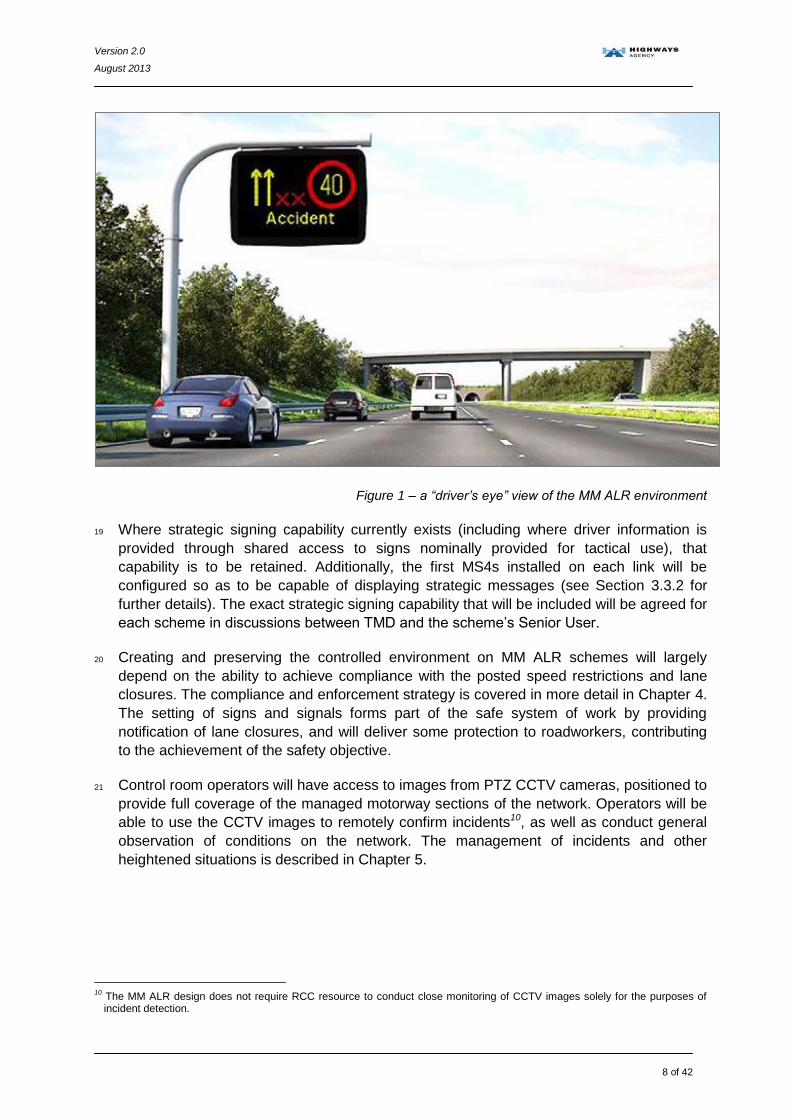
18 Figure 1 (overleaf) provides a “driver’s eye” perspective of a typical MM ALR scheme. The
various operational regimes and associated methods of driver information provision are
discussed in more detail in Chapter 3.
8 TD 69/07: “The location and layout of lay-bys and rest areas”
http://www.dft.gov.uk/ha/standards/dmrb/vol6/section3/td6907.pdf
9 In comparison with the construction, operation, maintenance and renewal costs of an MM HSR scheme designed to IAN 111/09
Version 2.0
August 2013
8 of 42
Figure 1 – a “driver’s eye” view of the MM ALR environment
19 Where strategic signing capability currently exists (including where driver information is
provided through shared access to signs nominally provided for tactical use), that
capability is to be retained. Additionally, the first MS4s installed on each link will be
configured so as to be capable of displaying strategic messages (see Section 3.3.2 for
further details). The exact strategic signing capability that will be included will be agreed for
each scheme in discussions between TMD and the scheme’s Senior User.
20 Creating and preserving the controlled environment on MM ALR schemes will largely
depend on the ability to achieve compliance with the posted speed restrictions and lane
closures. The compliance and enforcement strategy is covered in more detail in Chapter 4.
The setting of signs and signals forms part of the safe system of work by providing
notification of lane closures, and will deliver some protection to roadworkers, contributing
to the achievement of the safety objective.
21 Control room operators will have access to images from PTZ CCTV cameras, positioned to
provide full coverage of the managed motorway sections of the network. Operators will be
able to use the CCTV images to remotely confirm incidents10, as well as conduct general
observation of conditions on the network. The management of incidents and other
heightened situations is described in Chapter 5.
10
The MM ALR design does not require RCC resource to conduct close monitoring of CCTV images solely for the purposes of incident detection.

Version 2.0
August 2013
9 of 42
2.4 Operational Implications of the MM ALR Design
22 The MM HSR schemes currently in operation have successfully demonstrated how the
provision of additional capacity on busy parts of the network can have a positive impact on
performance metrics such as journey time variability and safety.
23 Delivering a controlled environment encourages compliant driver behaviour, which is a key
element in ensuring that managed motorway schemes can be safely operated. The design
features outlined in Section 2.2 are intended to ensure clear, appropriate and
unambiguous information is provided to drivers, for example regarding speed limits or lane
availability. Information should be delivered to the driver in such a way that it does not
cause overload or leave the driver in doubt as to what compliant behaviour is required of
them.
24 Simulator work11,12 has been used to provide assurance that the design will perform as
expected, prior to actual on-road implementation. A range of different trials were designed:
to measure the effect of varying the distance between successive gantries; compare driver
responses to overhead and verge mounted information; test comprehension of different
sign configurations; and evaluate sign obscuration on driver behaviour.
25 The “Demonstration of Meeting Safety Objective Report”13 shows that the generic safety
objective for all road users (as defined in GD 04/12: “Standard for Safety Risk
Assessments on the Strategic Road Network”14), can be met.
26 The philosophy of MM ALR is to reduce the amount of infrastructure required to operate
safely (which will have a corresponding impact on the amount of maintenance required)
though by its very nature this will be greater than for a D3M. In comparison with the MM
HSR design defined by IAN 111/09, the MM ALR design will completely eliminate the
requirement for dedicated hard shoulder monitoring (HSM) CCTV cameras, and their
associated control systems, and lead to a corresponding drop in civil infrastructure
expenditure: with fewer gantries being required; fewer dedicated refuge areas constructed;
and in many cases a reduced amount of near side vehicle restraint system needed - since
there will be fewer assets to protect.
27 The MM ALR design is also expected to result in lower whole-life operational costs.
Eliminating the need to check the dynamic hard shoulder is clear before opening it will
remove this element of operational workload in the control room, which on current
schemes is typically concentrated in the peak periods approaching the morning and
evening rush hours. Reducing the amount of technology installed while improving the
ability to remotely detect, diagnose, and repair faults will further reduce the costs of
maintenance, though ensuring safe maintenance access without a dedicated hard
shoulder will introduce certain challenges, which are addressed further in Chapters 6-8.
11
http://www.highways.gov.uk/knowledge/projects/managed-motorways-2-concept-development
12 http://www.highways.gov.uk/knowledge/projects/future-managed-motorways-concept-development-simulation-studies/
13 Copy available at:
http://www.highways.gov.uk/knowledge/projects/managed-motorways-all-lane-running/
14 http://www.dft.gov.uk/ha/standards/dmrb/vol0/section2/gd0412.pdf

Version 2.0
August 2013
10 of 42
28 Providing and preserving the controlled environment is expected to contribute towards a
scheme meeting the road user safety objective, through a reduction in frequency and
severity of collisions. This will have a corresponding impact on the resources required for
incident management. The implications of operating an MM ALR scheme on the HA’s
Traffic Management Directorate, including the Traffic Officer Service, are discussed in
more detail in Chapter 9.
29 Further resourcing benefits may be realised in future through increasing the centralisation
of certain functions (for example, re-routing all ERT calls to a single location). This is not
currently possible for MM HSR schemes, given the need for localised operation of a
dynamic hard shoulder.
30 With the majority of driver information now being provided through verge mounted signs
(as opposed to solely through AMIs on overhead gantries), both the frequency of traffic
management associated with offside lane closures and the challenges of conducting
emergency and routine repair and maintenance of infrastructure positioned above live
lanes are expected to reduce significantly. Provision of concrete central reserve barrier will
also contribute to a reduction in maintenance activity on the off-side of the carriageway.
31 The MM ALR design ensures that the additional capacity provided by the extra lane is
available by default, meaning there are no critical technology faults that would prevent the
extra lane from being made available to traffic.
32 Unlike MM HSR schemes, this additional capacity will be available at all times, without
necessarily requiring speed restrictions to be implemented.
33 The MM ALR design is not fundamentally different to those sections of the existing
motorway and multi lane all purpose trunk road network that do not have a hard shoulder.
However, it has the added advantage of having technology capable of detecting and
monitoring events that are happening on the network, coupled with dedicated systems able
to communicate appropriate advice or instructions to drivers, such as lane availability or
mandatory speed limits. When these are used together, they help to create the necessary
controlled, compliant environment.
34 In an emergency, drivers can exit the network at the next available downstream junction, or
stop in a refuge area. The hard shoulder adjacent to an exit slip may also be considered to
provide a safe location to stop, however they will not usually be fitted with an ERT.
35 There will be no automatic alert to RCC operators whenever a vehicle enters or leaves an
ERA15, however the driver will be instructed by fixed signs in the ERA to contact the RCC
using the ERT. Operators will be able to monitor the vehicle using CCTV, and if necessary
dispatch a TOS patrol and/or set signs and signals to assist the vehicle’s safe exit.
15
There is no automatic alert to the RCC when a vehicle enters an ERA because there is no dynamic lane alongside the ERA for the RCC to manage as there is in the MM HSR design, and provision of the alert does not mitigate any specific hazards. This is in line with the rest of the network, where there is no automated alert if a vehicle enters the hard shoulder or lay by. There is no requirement for the RCC to monitor an ERA unless alerted via the ERT or some other means that they need to do so.

Version 2.0
August 2013
11 of 42
3. Operating Regimes
36 The following operating regimes describe, in broad terms, how a generic MM ALR scheme
built to IAN 161/13 would be operated under ‘normal’ conditions, during both the peak and
off-peak periods16.
37 They set out the principles of how the Highways Agency and other stakeholders will
respond to certain circumstances in order to ensure the intended benefits of the scheme
are realised.
38 RCC Operators will be able to remotely monitor network conditions, confirm incidents and
(where they are visible) verify signal settings by utilising the PTZ CCTV coverage provided
throughout the scheme. The MM ALR design and operation does not of itself require
additional close monitoring for schemes, although given that MM ALR schemes tend to be
on the busiest parts of the network, TMD may consider them higher priority in terms of
supervision and monitoring.
39 The scenarios outlined below do already exist on the network. For example, there are
sections of motorways without a dedicated hard shoulder, and this environment is typical
on the multi lane APTR network. Maintenance work is conducted on these sections, and
incidents do occur and are managed. Therefore in many cases, there will be existing policy
and procedures that may be suitable for use in these situations with only slight modification
or extension. On-road and control room based staff will be provided with (and trained in the
use of) suitable procedures prior to the first MM ALR scheme becoming operational in that
region.
3.1 Off-Peak Operation
40 The off-peak period is expected to occur typically on weekdays; starting in the late
evening, and continuing overnight. Off-peak conditions may also apply throughout the
weekends; or between the morning and afternoon peak periods (the “inter-peak”),
depending on the location and traffic patterns.
41 By definition, during off-peak operation traffic volumes will be at their lowest. With all lanes
available for traffic to use, headways will be large, with traffic flowing freely. The national
speed limit will apply, and electronic signs and signals will not be required for purposes
relating to the operation of MM ALR, and as such will remain blank (if not required for
other, non-managed motorways related purposes such as strategic signing, or campaign
messages, etc).
42 There are no additional requirements introduced by an MM ALR scheme during these
periods of off-peak operation, (over and above the normal roles and responsibilities of
operational staff). The off-peak period provides the most appropriate conditions to perform
maintenance or other activities that may impact network availability, without unduly
compromising network performance.
16
Management of ‘abnormal’ conditions, including the presence of debris or broken down vehicles, abnormal load movements, severe weather, and road works are addressed in Chapter 5 of this document.

Version 2.0
August 2013
12 of 42
3.2 Operation During Peak Times
43 The peak period will usually occur on weekdays: typically starting in the morning and
extending into the early evening. Certain locations may also routinely experience peak
conditions outside of these times – this will usually be apparent from the traffic flow profiles
generated as an early deliverable by scheme designers and recorded in the Operating
Regime (combined) PCF product; but may also be generated by infrequent demand
increasing events (e.g. concerts, sporting events, etc).
44 During peak times traffic volumes will be higher. The extra capacity provided by the
conversion of the hard shoulder to an additional running lane may help to increase
headways, but on occasions, flow breakdown may still occur.
45 The queue protection system will continuously monitor the flow of vehicles, and when
necessary the congestion management system will trigger the automatic setting of
appropriate mandatory speed restrictions, applicable to the entire carriageway, in an
attempt to first prevent, and subsequently limit the effects of flow breakdown.
3.3 Provision of Driver Information
3.3.1 Tactical Driver Information
46 To encourage compliant driver behaviour, information relating to current network
conditions (e.g. speed restrictions, lane availability, etc) will be provided through roadside
infrastructure. Although some driver information will be provided through lane specific
overhead signals, the majority will be displayed using verge mounted variable message
signs (MS4).
47 Modifications to the signal control software will enable a single variable message sign to
display three simultaneous elements: in addition to the speed restriction and supporting
text legend, the sign will also be able to display either a warning pictogram (typically a ‘red
triangle’) as shown here:
Or alternatively, a lane closure aspect, as indicated in the example below:

Version 2.0
August 2013
13 of 42
48 Initial discussions with DfT identified the need to develop a lane closure aspect capable of
conveying an immediate lane closure. Research led to the development of the ‘red X’
variant indicated above. The HA have now agreed the relative locations of display
elements with the various sign manufacturers, and are working with DfT to formally
introduce the sign into relevant legislation.
49 All message signs will retain the capability to display a higher priority message should the
need arise. Newly approved messages will be incorporated into the VMS message
prioritisation hierarchy prior to the first MM ALR scheme becoming operational. A revised
version of IAN 162/12 (HA Policy for the use of Variable Signs and Signals) is also due to
be released prior to the launch of the first scheme, which will for the first time encompass
the use of signs and signals on all variants of Managed and Controlled Motorway designs.
3.3.2 Strategic Driver Information
50 When variable message signs are used to display combinations of speed limits, lane
closure aspects or pictograms, they will not be available to display text associated with
strategic traffic management or driver information. This is because of the potential
confusion for road users if the tactical information is displayed on the same sign as
strategic information.
Retained infrastructure
51 To ensure that the strategic signing capability is not lost during the peak hours of
operation, pre-existing strategic VMS (usually 3x18 MS3s) will be retained. There may be a
need to re-position these signs within the link to ensure the sequence of sign and
signalling installations on the approach to a junction follows the design set out in IAN
161/13.
52 At some locations, other (non-strategic) VMS are regularly used by the National Traffic
Operations Centre (NTOC) to display Strategic Traffic Management or Driver Information
messages, and this capability may also need to be retained. The exact level of provision
on each scheme will be determined by the Senior User, following consultation with NTOC.
53 Messages generated by the MIDAS subsystem usually have a higher priority than strategic
message settings, and as such would overwrite them. To prevent this, any retained
messages signs will be prevented from displaying MIDAS-generated queue protection
information. This can be achieved within the site data by removing the retained signs from
MIDAS pointers, where such systems exist.
Additional infrastructure
54 The IAN 161/13 design requires the first gantry downstream of a merge to house both lane
specific AMI signals and an MS4 message sign. As information relating to lane availability
and/or speed restrictions will be provided at that location using the AMIs, the MS4 sign is
available to show supporting text legends of a strategic nature.
55 The MS4 signs co-located with AMIs on the gateway portal gantry should therefore be
prioritised for strategic use within the message hierarchy. NTOC will be granted lower
priority access to the other MS4s within the scheme, thereby permitting strategic use when
not otherwise required for tactical purposes.

Version 2.0
August 2013
14 of 42
3.3.3 Speed restrictions
56 One key difference between a conventional and managed motorway is that variable speed
limit(s) displayed within a managed motorway scheme will be mandatory, whereas on a
conventional motorway they are advisory. To prevent conflicting information being provided
to drivers, any signalling infrastructure retained within a scheme will be configured such
that it is no longer capable of displaying advisory speed limits.
57 The speed limit will be enforced using strategically positioned HADECS cameras able to
detect and record speeding offences and initiate the prosecution process. It is therefore
critical that the displayed speed limit is appropriate to prevailing traffic conditions to protect
the credibility of the system and enforcement regime.
58 The congestion management system will determine the speed limit(s) necessary to keep
traffic flowing smoothly: where a speed restriction is generated, signals and/or message
signs will display appropriate mandatory speed limits.
59 Where the national speed limit is in operation, the signs and signals will either be blank
(e.g. if there is no congestion), or will display the standard national speed limit symbol (e.g.
to communicate that a previous speed restriction no longer applies). This will be
determined by the signalling rules.
60 At locations where speed restrictions are communicated using lane specific signals, the
same speed limit will be displayed above all the open lanes of a particular carriageway17.
61 Although DMRB permits a maximum drop in the speed limit displayed on consecutive
signals of 30mph; for safety reasons, operational policy is that the speed limit should not
drop by more than 20mph. There may be instances on MM ALR schemes where the
distance between signals makes even a 20mph drop in speed limit undesirable. Each
Scheme needs to consider this issue when preparing their Operating Regime (combined)
PCF product.
62 When a primary signal is set, the signal sequencing rules will result in appropriate
secondary supporting information being automatically set, based on the primary settings
and the distance between signals.
63 Configuration settings for the queue protection system (e.g. speed/flow threshold) will need
to be tuned and reviewed regularly to ensure that appropriate speed limits continue to be
set. RCC operators should note any instances of inappropriate speed limits so that these
can be considered as part of this review, for example, sections where queues on the exit
slip routinely build back onto the mainline generating speed limits over all lanes where the
offside lane is free flowing. This is particularly important on a managed motorway given
that speed limits are mandatory and there is a requirement to protect the credibility of the
enforcement regime.
17
With the exception of lane specific signal gantries which span multiple carriageways – for example those at complex junctions which extend across both the mainline carriageway and a parallel exit slip road or diverge.

Version 2.0
August 2013
15 of 42
4. Compliance and Enforcement
64 A compliant environment is one in which drivers understand what is expected of them and
behave accordingly. This is particularly important with MM ALR, where speed limits and
lane configurations may change dynamically, and where the controlled environment
provides the mitigation for some of the hazards associated with the removal of the hard
shoulder, contributing to the design meeting the safety objective.
65 In undertaking the design, Designers should have due regard for the operation of the
scheme and ensure that the creation of a compliant environment is undertaken in a holistic
way for the entirety of the scheme, including the lead-in from the section immediately
upstream and the lead-out into the next adjacent section downstream.
66 In designing for and evidencing that compliance can be achieved, Designers should
consider the application of “the 4 E’s” (Engineering, Education, Encouragement and
Enforcement) and how, when appropriately implemented, these will achieve a compliant
and operable environment that meets the scheme objectives.
4.1 Compliance Issues Specific to MM ALR
67 The MM ALR design introduces a number of areas where compliance may be affected:
Area of potential Non Compliance Comment
Exceeding Variable Mandatory Speed
restrictions
Does not arise on a conventional motorway
where any variable speed limits are
advisory
Driving under Stop Indicator (Solid Red X)
signals displayed above running lanes, or
past closures set using lane closure aspects
on a message sign
Potential for more abuse on an MM ALR
scheme due to the greater volume of
signals and higher propensity for their use
Also expect more frequent lane closures
(due to the increase in live lane
breakdowns) and greater use of signals to
support maintenance.
Non emergency stops in ERA Does not arise on a conventional motorway,
(although unauthorised stops on the hard
shoulder are observed)
4.2 Achieving Compliance on Individual Schemes
68 As part of the Operating Regime (combined) PCF product, each MM ALR scheme is
required to produce a compliance strategy which should highlight any exceptions to the
“HADECS3 Implementation Guidance”. This Project Control Framework (PCF) product will
define the actions being taken by the scheme to ensure that an appropriate level of
compliance is achieved.

Version 2.0
August 2013
16 of 42
69 The advice in the “HADECS3 Implementation Guidance” regarding the deployment of
enforcement cameras, coupled with the generic compliance strategy, forms part of the
work of NetServ and the Emergency Services Liaison Team. This advice is to be complied
with unless exceptional circumstances warrant a departure, which must: be discussed with
the Regional Enforcement Co-ordinator; be agreed by the Scheme Senior User; be
accepted by the prosecuting authorities; and not conflict with the documented enforcement
agreements.
70 The compliance section of the Operating Regime (combined) PCF product includes a
requirement to assess the potential for non-compliance with specific rules; identifying any
safety hazards that non-compliance would affect, in order to determine the overall impact
on achieving the safety objective.
71 This assessment should take account of aspects such as: the physical characteristics of
the road; the proportion of different vehicle types expected to use the scheme; and levels
of motorist familiarity with managed motorways, recognising that the latter two may vary by
time and day. It should consider engineering, education, encouragement and enforcement
measures that could be deployed to improve compliance.
72 Compliance with signs and signals improves when drivers understand why they have been
set. Wherever possible, supporting information (pictograms or text) will be set on the
message signs to explain why lane closures and/or reduced speed limits have been
implemented.
4.3 Agreements with Enforcing Bodies
73 For MM HSR schemes, the HA’s Emergency Services Liaison Team agreed a National
Enforcement Strategic Agreement between the Highway Agency, the Association of Chief
Police Officers (ACPO), the Crown Prosecution Service (CPS) and Her Majesty’s Courts
Service (HMCS) on the enforcement regime for contravention of Variable Mandatory
Speed Limits. A revised version has been produced to reflect the MM ALR design.
74 The intention is that the processing of offenders is conducted by one or two centralised
Police Fixed Penalty Offices within a given region; with the payment of fixed penalties
centralised into one or two Court Offices and the prosecution of offenders in one or two
Magistrates’ Courts per region. Processing will be done regionally to encourage consistent
standards. Regional Enforcement Coordinators within NDD Directorate will be responsible
for managing the evidential trail to ensure that variable mandatory speed limits can be
enforced; and for maintaining local Memoranda of Understanding (MoU) with the Police,
which will be set up during scheme delivery.
75 Similarly a jointly agreed MM Enforcement National Guidance Framework (ENGF)
document sets out the national principles, processes and procedures for enforcement. This
framework forms the baseline for local agreements, and will be revised to incorporate the
MM ALR design features prior to the first scheme becoming operational.

Version 2.0
August 2013
17 of 42
4.4 Achieving Compliance with Specific MM ALR Features
4.4.1 Variable Mandatory Speed Limits
76 Variable Mandatory Speed Limits (VMSL) will be enforced through the Highways Agency
Digital Enforcement Compliance System (HADECS).
77 The HA will reimburse the local Police Forces for the resource to process and prosecute
Variable Mandatory Speed Limit offences on MM ALR schemes. The enforcement of the
national speed limit will remain at the discretion of the local Police Force.
78 Each scheme will need to consider how many HADECS cameras it requires and where
they should be deployed, in accordance with the “HADECS3 Implementation Guidance”.
79 If the RCC identify or are made aware of instances where automatically set speed limits
are not credible or appropriate to traffic conditions, they should take immediate action to
remove or amend those speed restriction settings. Where displayed limits are clearly not
reasonable, compliance will be affected both on the link on which they are signed, as well
as potentially on nearby links.
80 Once an incorrect or inappropriate sign has been removed, the RCC should notify both the
Police, so that compliance with speed limits is not enforced during this period; and Traffic
Technology Division, so that the cause of the incorrect setting can be investigated.
81 The Police may refuse to enforce limits that are clearly not reasonable, or which regularly
lack credibility in their setting.
4.4.2 Lane Closures
82 As with the rest of the network, any enforcement of Red X (Stop) signals will need to be
carried out by the Police at the scene.
83 Similarly, Police at the scene may prosecute drivers for dangerous driving offences,
including failure to comply with lane closure aspects. Full carriageway closure aspects are
mandatory when accompanied by flashing red lanterns.
4.4.3 Non Emergency Stops in ERAs
84 Data collected from MM HSR schemes indicates that refuge areas are routinely used for
non-emergency (and therefore unlawful) stops. Evidence from sections of the network
where there is reduced provision for stopping (such as through road works, on bridges, or
on elevated sections of road) shows that the location of refuge areas can influence the
frequency of vehicle stops, according to whether they are seen as a desirable place to stop
by the public.
85 It is anticipated that MM ALR schemes will experience a reduced rate of non-emergency
stops compared to the levels observed before the scheme was built. The hazards
associated with the entry, occupancy and exit of ERAs are also a factor that has been
considered in determining their provision within the MM ALR design.

Version 2.0
August 2013
18 of 42
86 Engineering design will have a particular impact on the appropriate use of Emergency
Refuge Areas, given their potential attractiveness to drivers as a place to make short
duration stops. Observed examples of non-emergency (and therefore illegal) use include
drivers stopping for phone calls, comfort breaks, map reading, tachograph breaks, etc.
87 Education of road users is an important tool to remind them of the lawful purposes of
ERAs, and of the dangers inherent in making stops in ERAs for non-emergency use.
Scheme designers should consider the particular demographic of the expected users of
their scheme to understand what type of non-emergency stops might be expected. For
example, evidence suggests that where freight users constitute a high proportion of traffic,
ERAs may be used more frequently for tachograph breaks. These issues will be addressed
in the scheme’s Communications Plans PCF Product.
88 The MM ALR design requires each ERA to be fitted with a pair of fixed “No stopping except
in emergency” signs (to TSRGD diagram 642.3) to further discourage unlawful use.

Version 2.0
August 2013
19 of 42
5. Management of Incidents and other Heightened Situations
89 Experience has shown that creating and maintaining a controlled driving environment can
result in a reduction in both the frequency and severity of collisions. However, with the
removal of the hard shoulder, the number of live lane obstructions is expected to increase,
since a proportion of the vehicles that would previously have stopped on the hard shoulder
will now be unable to reach the next refuge area or exit slip, and will therefore have no
option but to stop in one of the live lanes.
90 Once an RCC operator is made aware of an incident (for example: through an automated
alert from the queue protection system, a phone call, or by some other means) the CCTV
cameras can be used to validate the location and confirm the key features of the incident.
91 The RCC operator has the ability to set a lane closure pattern with supporting information
messages and appropriate reduced mandatory speed limits. This will warn approaching
drivers of the potential hazard, enabling them to safely reduce their vehicle’s speed to
appropriate levels whilst merging into the remaining available lanes past the scene.
5.1 Dealing with Incidents - Key Differences on an MM ALR Scheme
92 On both MM HSR and MM ALR schemes, as compared to a conventional motorway, there
is a greater need for agreements (see Section 5.4) and clear communication between the
Highways Agency, and “Core Responders”. In this context, the term ‘Highways Agency’ is
used to include the RCC and on-road Traffic Officer Service, as well as Maintenance
Service Providers, the National Vehicle Recovery Manager and any other parties
contracted by the HA. The term ‘Core Responders’ is used to refer to the Emergency
Services, to Vehicle Recovery Services, and to private Motorist Assistance Organisations
involved in responding to or otherwise managing an incident.
93 This greater need for commonly agreed processes and procedures arises due to the
different operating environments encountered between managed motorway schemes and
conventional motorways. The increased deployment of technology on the network provides
staff in the relevant control rooms with greater knowledge of what is happening during
incidents on the strategic network, as well as the opportunity to assist the on-road
response by setting supporting signs and signals and providing information to responders,
even while they are still en-route to the scene.
94 As with incidents on any road, the management process can be considered in four distinct
phases, namely: Incident Detection & Verification; Initial Response & Access; Scene
Management; and Network Restoration.
95 From the perspective of responding to and managing incidents and other ‘unusual’
situations, the main differences between a standard three lane motorway (D3M), and an
MM ALR scheme are described overleaf:

Version 2.0
August 2013
20 of 42
Incident Detection & Verification:
o The controlled environment and additional capacity mean there is likely to be a
reduction in both the frequency and the severity of collisions on MM ALR when
compared to D3M; however most incidents will now affect a live lane.
o During busy periods, a live lane obstruction will quickly result in congested
conditions, enabling slow moving or stationary vehicles to be detected by the
queue protection system. This will automatically set message signs designed to
help prevent secondary incidents and will also serve to alert the control room.
o During off-peak conditions (typically high speed / low flow environments), the
majority of vehicles would be able to ‘coast’ to a place of refuge18.
o CCTV camera coverage will enable any incident to be quickly verified and an
appropriate response determined by the control room, enabling the setting of
lane closures using signs and signals to further protect the scene. o As with all live lane incidents, details should be passed to NTOC for onward
dissemination;
Initial Response & Access:
o With the conversion of the hard shoulder to a controlled running lane,
responders will need to attend incidents without relying on a dedicated access
route. o Signs/signals can be set to facilitate responder access using appropriate
lane(s);
Scene Management:
o Mandatory Speed Limits, whether automatically generated by a queue
protection system, or manually set by the operator, help to create and maintain
a controlled environment to protect those involved in managing the incident;
o Mandatory Speed Limits may be shown on either signs or signals, with
consecutive information points provided at maximum intervals of 1500m to
ensure all drivers receive adequate guidance;
o Using verge mounted variable message signs provides operational flexibility, as
the speed restriction can be accompanied by appropriate combinations of lane
closure aspects, pictograms, or text on a single piece of infrastructure;
o Information and instructions displayed on the variable message signs are
applicable to the entire carriageway; o The lack of hard shoulder will mean that the RCC may be requested to set
signs and signals, for example to protect a lane for police/TOS to stop or escort vehicles, or to assist with the recovery of a live lane obstruction;
Network Restoration:
o With no hard shoulder, a greater proportion of incidents will now be expected to
impact live lanes;
o Vehicles will need to be recovered to an off–carriageway location, such as an
ERA. Debris will also need to be cleared from live lanes;
o Refuge areas may be utilised as temporary off-network storage locations. The
requirement in IAN 161/13 that refuge areas are provided at intervals not
greater than 2.5km will typically result in the provision of at least one refuge
area per link.
18
http://assets.highways.gov.uk/specialist-information/knowledge-compendium/2011-13-knowledge-programme/MM-ALR_Evaluation_of_the_Provision_of_Refuge_Areas.pdf

Version 2.0
August 2013
21 of 42
5.2 General Approach to Managing Incidents
96 Variable signs and signals are the primary mechanism through which the RCC can control
traffic on a managed motorway.
97 Before the lanes that are affected by an incident are confirmed, all signs and signals set
will be non lane specific (i.e. the same advice applies to all lanes). Current policy19 dictates
that until a report is confirmed, a 50mph restriction is put in place, supported by message
signs bearing a legend such as “Incident”.
98 Once the lanes that are affected by an incident have been confirmed, lane specific
closures will be set on the most appropriate signals (for example displaying a ‘lane closure
aspect’ on a variable message sign, or stop signals on gantries with lane specific AMIs).
99 Once a lane closure has been set, the signal sequencing rules will set secondary signals
(including upstream lane diverts, downstream ‘end’ aspects, and appropriate speed
restrictions throughout the area). At any time RCC operators may override an automated
speed restriction with a lower speed limit. RCC operators should ensure that all
appropriate signs and signals are set (or cleared) according to the requirements of the
Lead Responder on scene.
100 Compared to a conventional motorway, the increased provision of signs and signals on
MM ALR means that many more drivers will be able to see messages displayed at the
roadside. This increases the potential benefit from signing as it enables the Highways
Agency to communicate with trapped traffic following an incident, a strategy that is
currently being considered as part of the signs and signals policy review.
5.3 Operational Challenges posed by MM ALR
101 The MM ALR design will affect the way in which some operational tasks are carried out,
and the manner in which some existing services are delivered. The following sections
discuss some of these operational challenges in more detail.
5.3.1 Ability to Confirm Incidents
102 The “Highways Agency policy for the use of Variable Signs and Signals” set out in IAN 162
states that lane specific signals and VMS messages related to an incident can only be set
once the location and the lanes that are affected by the incident have been confirmed by
an approved source agreed by the Traffic Officer Service (these approved sources include
a Police Officer, Traffic Officer, traffic incident management vehicle at the scene,
MAC/MSP, TechMAC/RTMC, or NTOC).
103 Once alerted, the full PTZ CCTV coverage will usually enable RCC operators to remotely
confirm the presence and details of an incident, and provide an appropriate response.
19
The current version of IAN 162: “Highways Agency policy for the use of Variable Signs and Signals” was released in December 2011. An update is planned to be released prior to the first operational MM ALR scheme.

Version 2.0
August 2013
22 of 42
5.3.2 Accessing the Scene
104 As soon as possible after confirmation of an incident, the RCC Operator should identify the
most appropriate access route for Emergency Responders and advise them accordingly.
Once confirmed by the Emergency Responders, the RCC should set the signs and signals
necessary to clear and protect this route. Guidance exists in procedures as to the factors
to consider when selecting which is the most appropriate lane to close.
105 If the TOS can convert a lane into a sterile area and can manage the incident from there to
release the traffic, this should be their first choice, enabling access to the scene for other
responders. If they cannot clear a lane (and if the situation warrants it) they may consider
implementing reverse flow, in readiness for larger response vehicles and recovery
operators.
5.3.3 Broken Down and Abandoned Vehicles
106 Traffic Officers have powers under the Removal and Disposal of Vehicles (Traffic Officers)
(England) Regulations 2008 that enable them to deal with vehicles that have broken down
and are either causing an obstruction or danger to others; are in contravention of a
restriction or prohibition; or appear to have been abandoned without lawful authority.
107 On the rest of the network, where a vehicle has stopped in a location such that it does not
cause an obstruction or danger (and if there is no police interest in the vehicle), drivers are
given a "reasonable" time to organise their own recovery. If suitable arrangements are not
or cannot be made, a statutory removal may be invoked by Traffic Officers.
108 As an MM ALR scheme has no hard shoulder, all lanes are live lanes. Any vehicle that is
unable to leave the main carriageway (by continuing to the next exit slip road, or stopping
in a refuge area), will by definition become a live lane breakdown, as it will cause an
obstruction.
109 If Traffic Officers are suitably trained and equipped, they will clear broken down vehicles to
the nearest place of safety, which may be an ERA, a motorway service area, or a hard
shoulder. This could regularly involve towing vehicles for distances up to 2.5km, and in
instances where the nearest place of safety is occupied or otherwise unavailable there
may be a requirement to tow for even greater distances.
110 If Traffic Officers are unable to clear the vehicle (for example due to it being overweight, or
damaged), they will set out emergency traffic management and follow the usual Statutory
Removal process. Once in attendance they are to remain with the vehicle until it is
removed or otherwise protected. Work is underway with the Vehicle Recovery Team to
determine the best way to enhance response times on MM ALR sections for those vehicles
that the TOS cannot clear.
111 If a vehicle is broken down in (or cleared to) a refuge area or the hard shoulder of a slip
road, the on road TOS patrol - as for any other road - should make an assessment of the
obstruction or danger posed by that vehicle to determine whether a statutory removal is
justified, or whether “owner’s choice” of vehicle recovery can be used.

Version 2.0
August 2013
23 of 42
5.3.4 Debris Retrieval
112 As elsewhere on the network, debris is categorised as either that requiring immediate
collection (e.g. debris of a distressing or hazardous nature); or routine debris (e.g. tyre or
exhaust debris).
For “immediate collection” debris, an incident assessment will be made by the
attending Traffic Officer who will determine whether the debris should be removed
to the edge of the carriageway (or verge), or left in situ awaiting removal by the
maintenance service provider.
o If the debris is to be left in situ, the TO will remain at scene, and
deploy appropriate live lane procedures.
o If the debris is to be left at the edge of the carriageway, the TO may
need to return to support the Service Provider.
For “routine collection” debris, the TOS may need to deploy a 4 lane rolling road
block to temporarily hold traffic while the debris is removed to the verge and placed
near to a marker post. The Maintenance Service Provider will return in periods of
lower flow, or when other maintenance work requires lane closures to collect the
debris. Supporting signs and signals will be set, as per agreed procedures, by the
RCC.
5.3.5 Severe Weather
113 The combination of message signs capable of displaying lane availability with supporting
text and pictograms, coupled with the ability to implement mandatory speed limits, provides
the operator with useful tools to mitigate the impacts of severe weather on traffic.
114 Certain weather conditions (e.g. fog, heavy rain) can reduce visibility and increase the risk
of accidents. This risk is primarily related to excess speed. If drivers are driving slowly due
to the conditions, the queue protection / congestion management system will automatically
set appropriate speed restrictions to reduce the associated risk of accidents. More
information regarding the use of message signs to communicate abnormal weather
information is contained within the “Highways Agency policy for the use of Variable Signs
and Signals”.
115 The Severe Weather Plan (SWP) produced by each Asset Support Contractor describes
the procedures and operational arrangements necessary for the delivery of an effective
winter service, and as such should identify network features (such as managed motorway
sections or ERAs) or local issues (such as high altitude or steep gradients) which require
special consideration.
116 The Severe Weather Plan will also define the process for snow clearance, for example by
setting out the number of lanes to be kept clear for a particular route, and the order in
which lanes should be cleared if a ‘phased’ approach is followed. Message signs and
signals can be utilised to display warning information, or inform motorists if certain lanes
are not available for use.

Version 2.0
August 2013
24 of 42
5.3.6 Road Works Management
117 As on the rest of the network, road works will generally be scheduled to take place at times
that minimise the impact on traffic. This means works will generally happen at night; in
periods of lower flow in the middle of the day; or at weekends. As these periods are
dependent on traffic flows, they will need to be agreed on a scheme by scheme basis
adopting the principles of intelligence based road space management20.
118 During road works, the contractor may request that the RCC set signs and signals to
support the set up, modification or removal of Traffic Management.
119 The current policy governing requests from contractors for signal settings is set out in
Annex F of IAN 162/12, the “Highways Agency policy for the use of Variable Signs and
Signals”. However the HA’s “Aiming for Zero” programme is anticipated to drive significant
developments regarding TTM design and advance signing provision over the coming
years.
5.3.7 Abnormal Load Movements
120 Managed motorways do not fundamentally affect the preferred times or routes for
abnormal loads and normal guidance should be followed in scheduling such movements
on an MM ALR scheme. As for other parts of the network, deviation from the agreed routes
should not be made without appropriate consultation21.
121 Managed motorways provide significantly enhanced capabilities to monitor the movement
of the abnormal load. The NTOC will have (if possible) established communication with the
driver of the abnormal load, and the RCC should communicate via the NTOC to ensure
that the driver is aware of downstream traffic conditions, and to facilitate communication
should an incident occur.
20
For example, a road works management tool which uses historic data to predict lane demand through road work schemes. This allows for lane closures to be planned so as to cause minimal congestion, thereby reducing delays and other impacts of congestion. 21
For Special Order Movements no deviation from the agreed route should be made without consultation with the Highways Agency. For all other abnormal loads, no deviation from the agreed route should be made without consultation with the Police Abnormal Loads Officer and/or Highway and Bridge authorities or RCC Team Manager outside office hours. Any deviation must be considered suitable by them before being used.

Version 2.0
August 2013
25 of 42
5.4 Emergency Responder National Agreements and Guidance
5.4.1 National Agreements
122 Responding to incidents on MM ALR schemes requires a collaborative approach that
reflects the national character of the managed motorways programme.
123 To support the above, the Highways Agency has established jointly-agreed national
positions with: the Association of Chief Police Officers; the Chief Fire Officers Association;
and the National Health Service Ambulance Chief Executive Group, regarding the
emergency response to incidents on existing MM HSR schemes. Work is underway to
reach similar agreements covering the response on MM ALR schemes, and to update the
Network Operations National Guidance Framework (NGF) to cover all managed
motorways.
5.4.2 Regional and Scheme Level Agreements
124 Each scheme will establish suitable regional agreements with the Emergency Services.
These agreements should replicate the principles of the national agreement, unless a
strong justification can be provided to deviate from them. Any variance should first be
agreed with the HA Traffic Management Directorate, and subsequently approved by the
Scheme’s Senior User.
125 The preference is for each region to have a single agreement, signed by all three of the
Emergency Services, as an addendum to the existing “Detailed Regional Operational
Agreements” that were set up when the Traffic Officer Service was created. However, it is
recognised that this may not be possible or desirable in all cases, and that individual
agreements with the Police, Fire and Ambulance services separate from the existing
Detailed Regional Operational Agreements may be necessary in exceptional cases.
126 Regardless of the precise form, these agreements will need to take the principles of the
national agreements, apply them to the characteristics of the individual scheme, and
record the agreed operating practices based on scheme-specific requirements. It is
anticipated that these agreements would record acceptance of the national principles apart
from where specific exceptions are deemed necessary; these exceptions are to be
included in chapter 5 of the scheme’s Operating Regime (combined) PCF product:
“Management of Incidents and other Heightened Situations”.
Version 2.0
August 2013
26 of 42
6. Meeting the Road Worker Safety Objective
127 The “Standard for Safety Risk Assessments on the Strategic Road Network” (GD 04/12)
defines road workers as either:
People directly employed by the Highway Agency who work on the SRN (e.g.
Traffic Officers); or
People in a contractual relationship with the Agency, including Agency National
Vehicle Recovery Contract operatives, all workers engaged in traffic management
activities and incident support services, and any other activities where live traffic is
present, (such as persons carrying out survey and inspection work).
128 There is no numerical objective or target for road worker accidents on MM ALR schemes,
but the risk must be managed ‘So Far As Is Reasonably Practicable’ (SFAIRP).
129 The MM ALR “Demonstration of Meeting Safety Objective” report contains a qualitative risk
comparison for specific road user groups; and shows that on balance, the safety objective
for road users is likely to be achieved.
130 The above report also concludes that the road worker safety objective can also be met
through the provision of concrete central reserve barrier, application of the ERIC22
methodology, and introduction of fixed taper points and controlled signing for the
installation of temporary traffic management. The Highways Agency's “Aiming for Zero”
strategy may also be applied to further reduce the risk to road workers (particularly during
maintenance and operation).
131 Designers retain a statutory duty through the Construction (Design and Management)
Regulations 2007 to reduce health, safety and welfare risks for (amongst other things) the
maintenance of completed highway schemes. Generic guidance exists23 regarding the
issues which must be considered by Designers and Maintenance Service Providers.
132 Each scheme should undertake its own specific review of the hazards associated with
maintenance, and ensure that the scheme has been designed in such a way that it can be
operated and maintained so that the risks are As Low As Reasonably Practicable
(ALARP).
6.1 Designing for Maintenance
133 There are two main threads to the strategy of reducing the risk exposure of maintenance
operatives through the scheme design:
Design the scheme to minimise the frequency with which future maintenance
interventions are required;
Design the scheme so that when a maintenance intervention is required, it can be
safely carried out.
22
The mnemonic ERIC (Eliminate, Reduce, Isolate, Control) is used to identify a hierarchy of risk control measures. 23
IAN 105/08: “Implementation of Construction (Design & Management) 2007” http://www.dft.gov.uk/ha/standards/ians/pdfs/ian105.pdf

Version 2.0
August 2013
27 of 42
134 In order to identify opportunities to lower the risk exposure of road workers, an ERIC
assessment considered all maintenance activities likely to be undertaken within a typical
MM ALR scheme. It then determined how frequently they occur, how they are currently
performed, and how they might be performed in future. This enabled mitigation measures
to be identified, allowing the risks to be managed in accordance with the ALARP principle.
6.2 The ‘ERIC’ approach to reducing risk
135 The following sections provide examples of risk reduction strategies under each of these
four headings (Eliminate, Reduce, Isolate and Control). Note that these items do not
constitute an exhaustive list, as each scheme will have specific local issues; and this
guidance does not detract from the Designer’s responsibilities under the CDM regulations.
6.2.1 Eliminate
136 The most effective hazard reduction strategy is to simply eliminate the requirement to
conduct maintenance at all. This could be achieved as follows:
Removal of Assets
137 Designers should catalogue all the assets that are currently installed within the scheme
boundary, identify all redundant or potentially redundant infrastructure, and assess
whether it should be removed. As is the policy for the rest of the network, non-essential
infrastructure or technology, including soft estate, should be removed.
6.2.2 Reduce
138 If a particular maintenance activity cannot be eliminated, it may be possible to reduce the
frequency with which maintenance access is required, or reduce the length of time the
maintenance activity takes. Opportunities include:
Reduce Site Visit Requirements
139 Designers should, in designing for maintenance, make every effort to reduce or eliminate
the need for roadside maintenance activities for new and existing equipment on the
mainline carriageway. Maintenance and repair should be undertaken away from the
network unless there is no other alternative.
140 Where possible, roadside technology should have remote access capabilities, allowing
faults to be detected, interrogated and in some cases resolved without requiring a site visit.
(This is covered in more detail in Section 8.3.5).
Bring Forward Renewal Programmes
141 In advance of the MM ALR scheme construction, the Highways Agency, designers and
maintenance providers should consider undertaking maintenance interventions that are
scheduled to take place during (or shortly after) the implementation of the MM ALR
scheme.
142 Assets should be left with at least a minimum residual life (to be agreed with the Senior
User, but likely to be 3 to 5 years) after the scheme has gone live. This activity will reduce
the amount of maintenance that needs to take place once the scheme is operational.

Version 2.0
August 2013
28 of 42
Utilise Low Maintenance Items
143 Designers should consider the use of longer life and/or lower maintenance items and
assets where they will need to be replaced or installed as part of the scheme. This
consideration should also include assets that have extended reactive maintenance periods
(e.g. curing of concrete on bridge repairs) as this will greatly reduce planned and reactive
maintenance requirements.
Plan for Access Restrictions
144 Maintenance Service Providers should take advantage of the TTM installed for the
construction period of the scheme to undertake any necessary longer term maintenance
activities, such as soft estate management, vegetation clearance for visibility, and other
routine maintenance activities. This will enable Maintenance Service Providers to reduce
the time spent performing maintenance activities once the MM ALR scheme becomes
operational.
Renew ‘Problem’ Assets
145 Designers should work with the existing maintenance service provider to identify whether
any existing technology assets are known to either be unreliable; or have unreasonably
short maintenance intervention intervals, and should consider replacing those assets with
more reliable alternatives or components requiring less frequent maintenance. Another
example might be to implement a policy of regularly operating ‘remote control’ signs to
improve their reliability.
6.2.3 Isolate
146 A risk can be isolated by separating the hazardous activity from the individuals exposed to
it, either by physical protection (e.g. through the provision of guarding) or by limiting access
(e.g. through the requirement for maintenance activity to only occur within predetermined
‘working windows'). Examples include:
Re-Positioning of Assets
147 Designers should assess all existing assets to ascertain whether any could be repositioned
to enable their maintenance activities to be conducted either off network, or from within a
designated area for maintenance. Where appropriate, items located in the former hard
shoulder (such as manhole covers) should be removed from what will become a
permanent running lane. The capital cost of moving the items should be weighed against
the operational costs and risks of maintenance, and the associated loss of capacity over
the life of the scheme.
Provision of Off-Network Access
148 It may be possible to provide safe maintenance access to both new and existing assets
without recourse to the motorway network (for example by locating the asset near to an
over-bridge with pedestrian access). However, locations which can be easily accessed by
maintainers may also increase the opportunity for asset theft, and so the guidance
provided within the HA Metal Theft Toolkit should be observed.
Version 2.0
August 2013
29 of 42
Combining Asset Locations
149 When installing new assets, designers should consider co-locating them to enable multiple
maintenance activities to be undertaken within the same deployment of Temporary Traffic
Management. The capital cost of co-locating items should be weighed against the
operational costs and risks of maintenance and the associated loss of capacity over the life
of the scheme.
6.2.4 Control
150 Control measures make it safer for the contractor to perform each maintenance activity, for
example by providing a greater degree of protection, or by reducing the exposure time.
Examples of controls include:
Improved Accessibility of New Assets for Maintenance
151 Designers should ensure new assets are positioned to facilitate maintenance access. This
could include locating components in refuge areas, or within a designated area for
maintenance. This may mean additional assets are required in certain circumstances, but
improving maintenance access is expected to deliver an overall safety and operational
benefit. Designers should also consider providing mechanical access facilities to assets as
part of the design.
152 The HA’s ‘Aiming for Zero’ strategy includes eliminating all carriageway crossings required
to establish TTM signing. This approach is being driven by the HSE and is fully endorsed
by HA Senior Management.
Fixed Taper Positions & Remote Signalling
153 Where off-network access cannot be safely provided, designers should identify fixed points
at which a cone taper can be installed in order to support the setting out and removal of
traffic management.
154 Sufficient taper locations should be identified to allow all the assets, including any signage
required to support traffic management, to be maintained within a suitable temporary traffic
management layout. Therefore, the frequency and location of the taper positions needs to
be agreed by scheme designers and the maintaining agent. (See also Section 8.3).
Improved Installation / Access Techniques
155 Designers and Maintenance Service Providers should review the technology assets to be
installed, and consider methods to enable easier/quicker swap out of faulty equipment to
reduce the time spent performing maintenance actions.
156 In accordance with current standards24 gantries are not to be provided with a fixed means
of access for inspection and maintenance. A departure from standard will be required if a
fixed means of access is required.
24
IAN 86/07: “Amendments to design requirements for Portal and Cantilever Sign/Signal Gantries”. http://www.dft.gov.uk/ha/standards/ians/pdfs/ian86.pdf
Version 2.0
August 2013
30 of 42
7. Determining the Approach to Maintenance
7.1 Contractual Requirements
157 The “Asset Maintenance and Operational Requirements” (AMOR) and the “Technology
Management & Maintenance Manual” (TMMM) together set out the HA’s requirements in
relation to the carrying out of maintenance and operational activities on the network. These
documents serve as the replacements to the Network Management Manual (NMM) and the
Routine & Winter Service Code (RWSC).
158 Contained within the AMOR and TMMM specifications is the requirement that the
Maintenance Service Provider adopts a risk based approach to the execution of
maintenance and operational activities, in order to deliver value for money whilst
demonstrating that risks are acceptably mitigated, with no detriment to the safety of either
road users or road workers.
159 The AMOR defines the primary risks to be mitigated by the maintenance service provider.
These are grouped in two key areas; safety and network availability:
Safety: risks must be mitigated to ensure that:
o the Area Network is not dangerous to traffic;
o the Area Network does not present an intolerable risk to road user or road
worker safety; and
o the Highways Agency is provided with a ‘special defence’ under Section 58 of
the Highways Act 198025.
Availability: risks must be mitigated to ensure the Maintenance Provider:
o secures the expeditious movement of traffic on the HA’s Area Network; and
o facilitates the expeditious movement of traffic on road networks for which
another authority is the traffic authority.
7.2 Delivering Efficiencies
160 A requirement of AMOR is that the Maintenance Service Provider prioritises their activities
to optimise the use of (and achieve the best value from) the available resources. They are
required to produce a Quality Plan, to include fully detailed Processes, Procedures and
Timescales in relation to inspection, make safe, and repair of the asset; detailing exactly
what activities the Provider will undertake to deliver the required outcomes whilst
maintaining a tolerable safety risk for the road user.
161 For an MM ALR scheme, this Quality Plan should reflect the fact that their ability to access
certain assets may be compromised by factors including physical access (e.g.: no hard
shoulder), or other restrictions (e.g.: no routine maintenance permitted during peak
periods).
25
Section 58 provides the defence that “the Authority had taken such care as in all the circumstances was reasonably required to secure that part of the highway to which that action related was not dangerous for traffic.”

Version 2.0
August 2013
31 of 42
162 The Maintenance Service Provider is also required to produce a Maintenance
Requirements Plan, detailing:
the planned Programme of Inspections;
the Response and Repair timescales, covering defect identification, verification,
response and repair; and
how work will be packaged to minimise network occupancy (including road space
booking requirements, traffic management requirements, and temporary traffic
regulation orders).
163 Designers and Maintenance Service Providers are to give careful consideration to the
requirement to minimise network occupancy, both from the point of view of reducing lane
closures and reducing the exposure of road workers to the risks of working adjacent to live
traffic. Hence the number of traffic management maintenance interventions should be
minimised.
164 The Maintenance Service Provider is required to deliver (and comply with) a Network
Occupancy Plan, containing occupancy booking procedures and pro-formas. They are to
also maintain a fully populated record of all occupancies and any activities which cause an
adverse impact on road users; with a view to optimising all occupancies, and minimising
the effect of activities.
165 There are no additional operational requirements for a “Permit to Access” system specific
to managed motorway schemes. The requirements set out in AMOR for a Network
Occupancy Plan which outlines the Provider’s Processes and Procedures for Managing
Network Occupancy are deemed to be sufficient. Under the ASC contract these general
requirements are considered to be a lump-sum duty which will not incur additional costs to
the Agency.
166 Effective communication systems will be needed to ensure that if the RCC needs to
request that maintenance personnel leave the network, the maintainer is able to comply
with that request in an expeditious manner. Any system employed should ensure that the
MAC/ASC is able to monitor and make contact with all contractors, including third-party
maintainers. Any ICT systems used to track road space bookings are to be operated
entirely by the MAC/ASC themselves, with no expectation placed on the RCC to access
these systems in order to obtain information.
167 AMOR also requires that separate plans are produced for key operational areas, including
the Severe Weather Service and Incident Response. These plans should detail the
activities which will be undertaken to deliver the required outcomes and avoid danger to
users of the highway.

Version 2.0
August 2013
32 of 42
8. Impact of MM ALR on Maintenance
168 MM ALR schemes comprise a specific mix of technology and civil infrastructure. These
assets require maintenance in order to remain functional, and so deliver the operational
and safety benefits required of the scheme. However, the scheme’s design itself changes
how Maintenance Service Providers carry out maintenance, due to factors including:
the pressure of road space booking, arising from the need to access the additional
technology assets, roadside infrastructure and field electronics installed as part of the
scheme design;
operational restrictions on the time periods during which maintenance activities are
able to be conducted, including the need to avoid lane closures during periods of high
demand; and
the lack of a hard shoulder from which to carry out maintenance, access roadside
infrastructure, or set out temporary traffic management (TTM).
169 The following sections describe some of the likely impacts that the MM ALR design is
expected to have on the ability to plan, schedule, and conduct maintenance activities; as
well as suggesting potential opportunities to mitigate those impacts.
8.1 Planning Maintenance Activities
8.1.1 Asset Inventory
170 With access to MM ALR schemes expected to provide additional challenges (when
compared to D3M sections), survey work may prove more difficult and so the planning of
routine maintenance activities needs to be more rigorous. During the construction phase
of the MM ALR scheme the scheme designer (supported by the maintenance service
provider, delivery partner and construction contractor) should collate a full asset inventory,
containing all assets, their quantities, location and condition, together with details of the
date and nature of the most recent maintenance activity.
171 This inventory is to be kept up to date during the construction period. Once the scheme is
operational, any survey activities necessary to keep the inventory current will need to be
carefully planned to maximise the utilisation of any temporary traffic management being set
out for maintenance work so as not to require any additional traffic management
installations.
172 The asset inventory should be used to establish appropriate asset management plans,
enabling work to be scheduled accordingly.
8.1.2 Plan for Incident / Longer Term Maintenance
173 Designers and Maintenance Service Providers will need to review both existing and new
structures within the MM ALR scheme to identify any structures or assets that require TTM
to be left in place for an extended period (i.e. longer than overnight), in order to allow a
repair to be completed.

Version 2.0
August 2013
33 of 42
174 Examples might include the repair of a bridge parapet where the curing of the concrete
requires protection for several days until the required minimum strength has been reached,
or assets where non-stock materials are needed to make a repair, but traffic needs to be
kept away from the vicinity while those materials are sourced.
175 Action plans for these circumstances need to be established and agreed, as it is a
requirement of AMOR that they are included in the Maintenance Requirements Plan.
8.1.3 Plan for Severe Weather
176 The permanent conversion of the hard shoulder into a controlled running lane will have an
implication on the procedures and operational arrangements necessary for the delivery of
an effective winter service plan for MM ALR schemes. Snow accumulations are likely to
be ploughed and stored in running lanes for a longer period of time; if snow is moved to
lane 1 arrangements for clearing slip roads will have to be made. Wider carriageways will
typically need echelon ploughing. Salting will require two passes instead of one to
effectively cover four lanes of running traffic. These arrangements will be defined in the
Severe Weather Plan (see also Section 5.3.5 for implications on the RCCs).
8.2 Scheduling Maintenance
177 The high traffic volumes that MM ALR schemes are expected to experience during a
typical weekday means that the main opportunity to conduct maintenance works will be
overnight. Closing lanes during working days is likely to create significant congestion and
delays to travellers. Hence weekday, inter-peak closures are not feasible (except for
emergency works). Therefore the majority of activities will need to be scheduled at night,
with additional temporary lighting provided as appropriate.
178 Intelligence based road space management will establish when it may be possible to
permit lane closures during daylight hours to allow activities that are deemed to be
unfeasible, or too high risk, to be carried out in the dark (e.g. litter picking, soft estate
clearance). This will be scheme specific: Designers and Maintenance Service Providers
should not assume that such a window exists; and so alternative methods of scheduling
maintenance access may be required.
8.2.1 Scheduling Planned Maintenance Activities
179 There is increased pressure to minimise the number of occasions when TTM is in place, to
minimise the safety risks to both road workers and road users, and to improve the
efficiency of maintenance activities.
180 The Maintenance Requirements Plan introduces the need to minimise network occupancy,
meaning the number of activities that are carried out during a single installation of
temporary traffic management will be increased wherever possible.
181 Adopting this approach becomes even more crucial on MM ALR schemes, where the
opportunities for maintenance access are reduced. However the ability to group
maintenance activities together is subject to maintainers having adequate resources
available to conduct the work, and there being no adverse impacts on safety associated
with the undertaking of a number of activities within the same area.

Version 2.0
August 2013
34 of 42
182 Consideration also needs to be given to the safety risk of the road user of delaying the
intervention of separate maintenance activities into a single traffic management
intervention.
8.2.2 Scheduling Reactive Maintenance
183 Defects and equipment failures are inevitable. Except where the item can be safely
accessed from off the network with the necessary tools, plant and materials; all repairs will
require TTM. Both the frequency with which faults or defects occur, and the time needed to
make a repair are key factors in determining the need for TTM.
184 Deciding when to undertake reactive maintenance requires an assessment of the
operational criticality of each component to enable the network to continue to be safely
operated despite the presence of a fault: either until a planned maintenance activity with
the required temporary traffic management layout is in place; or until sufficient ‘other’ faults
occur to enable them all to be repaired in a single maintenance intervention.
185 An exercise has been carried out to determine the availability requirements for each
roadside technology type from both an operational and safety perspective. These will then
be used to influence the target response / restore times defined within TMMM. This forms
the basis of the risk based approach outlined in AMOR, and should be accommodated in
the Maintenance Requirements Plan.
186 There is also the reverse opportunity in that some planned activities could be re-scheduled
to make use of a TTM installation required to fix a fault or defect.
8.3 Conducting Maintenance
8.3.1 Generic Safe Method for Placing TTM
187 Safe installation of TTM for maintenance has been identified as a key challenge for MM
ALR designers and operators. One potential approach to meeting this challenge is
demonstrated by the ‘generic safe method’26, a guidance document produced in
consultation with the Road Worker Safety Forum (RoWSaF) which includes features such
as fixed taper positions and dedicated advance signage.
188 Designers and maintainers are not required to emulate the generic safe method; rather
they should apply design for maintenance principles to ensure road worker hazards for a
particular scheme are adequately managed. The generic safe method merely
demonstrates one such approach.
8.3.2 Installation of Temporary Traffic Management
189 Where the need for a maintenance intervention cannot be avoided, TTM will be required.
The main differences when installing TTM on a road with four live lanes without a hard
shoulder involve the safe installation of the advance warning signs and the initial set up of
the taper. Once these are in place then the remainder of the installation is the same as for
a conventional motorway.
26
http://www.dft.gov.uk/ha/standards/tech_info/files/Generic%20Safe%20Method%20for%20Placing%20TTM%20FINAL.pdf

Version 2.0
August 2013
35 of 42
190 There are two key issues relating to the installation of TTM in an MM ALR environment: the
initial positioning of signs and taper cones has to take place in live lanes; and setting out
the offside signs to Chapter 8 would otherwise require workers to cross four lanes of traffic.
With concrete central barrier there is no effective position of refuge for a road worker
installing a sign adjacent to the barrier.
191 To combat this, the Aiming for Zero programme is currently sponsoring a number of
projects aimed at eliminating or reducing road worker exposure to risk during set up of
TTM, particularly those risks relating to the crossing of the carriageway on foot. For
example, project 1C1 is assessing the suitability of using AMIs to display variable
mandatory speed limits to support the setting up and taking down of TTM; while projects
1C2 and 1C3 are reviewing the use of variable signs and signals to communicate static
lane closures in advance of the works.
192 The Aiming for Zero programme is a rapidly developing workstream, and designers and
maintainers should be aware of potential TTM relaxations published in IANs during
scheme development and operation phases.
8.3.3 Pre-determined Taper Positions and Fixed Traffic Management Signs
193 Pre-determined taper positions and remotely operated traffic management signs may be
used to aid in the setting out of TTM. Dedicated electronic (or electromechanical) signs
installed upstream of each selected taper location at the distances described in Chapter 8
of the Traffic Signs Manual eliminate the safety hazards to the road maintainer created by
the requirement to physically place temporary fixed plate signs adjacent to a live running
lane. These signs may be mounted in either the verge or central reserve as required, and
can be operated remotely from an approaching maintenance vehicle (such as an Impact
Protection Vehicle) or from an accessible, secure, safe location (e.g. the RCC).
194 Aiming for Zero Project 1U will deliver guidance and specification requirements for the use
of post-mounted, remote-controlled message signs at roadworks; and is expected to
deliver by December 2013. Designers should consider whether the benefits of their
installation can be shown to outweigh the dis-benefits of introducing additional ‘permanent’
assets, particularly in the central reserve; especially as project 1S4 is considering the
removal of all offside signs on the approach to roadworks.
195 Sufficient taper locations are to be identified which allow all the assets, including any
signage required to support traffic management, to be maintained within a suitable
temporary traffic management layout. Therefore, the frequency and location of the taper
positions needs to be agreed by scheme designers and the maintaining agent.
8.3.4 Electronic Sign Utilisation
196 The number of dedicated signs required solely for advance warning of road works could be
reduced if the electronic signs and signals within the MM ALR design for driver information
and control are used to form part of the advance signing. For example, a fixed taper
location could be positioned ~1500m downstream from a sign or signal, which would be
used to display the appropriate legends and aspects for the 1 mile advance warning under
Chapter 8. This eliminates the risk to the road maintainer associated with placing the
equivalent fixed sign in a live running lane.

Version 2.0
August 2013
36 of 42
8.3.5 Remote Access to Technology Assets
197 Remote access to technology assets is being developed and delivered in two phases.
Phase 1 will deliver remote access to the latest generation of signs and signals; while
Phase 2 will add remote access capability to all IP-enabled devices, including CCTV
cameras.
198 Maintenance Service Providers should, wherever possible, make use of this facility to
minimise visits to the roadside. The Maintenance Service Provider will need to obtain
permission from the RCC to take over control of the piece of equipment, as they would
currently for physical repairs, to ensure that the equipment is not simultaneously required
for operational purposes.

Version 2.0
August 2013
37 of 42
9. RCCs and the Traffic Officer Service
9.1 Staffing Levels
199 An exercise is being carried out by the Managed Lanes & Policy Team to assist TMD in
reviewing their future staffing needs. The approach takes account of the resource
requirements that will be necessary to safely operate MM ALR schemes as intended.
Therefore no additional work will be needed to assess staffing levels for individual MM ALR
schemes in isolation.
200 The Operating Regime (combined) PCF Product for each scheme will need to record that
an assessment has been completed, and that the staffing requirements to operate the
scheme have been agreed.
9.2 RCC Space Requirements
201 As MM ALR schemes do not have a dynamic hard shoulder, there is no need for a hard
shoulder monitoring (HSM) subsystem to be housed within the RCC, so it is not anticipated
that any additional server space will be required for this purpose.
9.3 Traffic Officer Procedures for Managed Motorways
202 To ensure national consistency across managed motorways operations, a single,
standardised set of core procedures have been produced by the TOS Procedures Team,
for approval by both the National Health & Safety Team (NHST) and the Resource and
Capability Group27 (R&CG).
203 It is the responsibility of each scheme to identify any specific considerations that require a
“non-standard” operational procedure. In particular, the scheme will need to identify any
hazards that may not have been included in the MM ALR generic hazard log, and where
necessary determine appropriate mitigations.
204 The national TOS Procedures Team will work with each scheme to develop a set of
procedures to cover such scheme specific conditions and to gain the necessary approvals.
Where applicable these will form a set of regional procedures that will be described for
each TOS region. Such procedures may include setting of variable signs and signals for
TTM, and will need to ensure that operation of any permanent advance signs do not
conflict with signs and signals set by the RCC.
205 The core and regional (scheme specific) procedures will be held and maintained centrally
on the Traffic Officer Procedures Index on the Highways Agency Portal by the TOS
Procedures Team.
27
R&CG was formerly known as the Traffic Learning Centre (TLC)

Version 2.0
August 2013
38 of 42
9.4 Learning Requirements
206 The HA’s Traffic Management Division, through the Resource and Capability Group
(R&CG), will coordinate the national approach to all Traffic Officer learning requirements
associated with MM ALR schemes.
207 To deliver this work, R&CG will analyse the competence requirements associated with the
operation of each scheme for all TOS roles (mapping legal, safety and national standards
requirements), and determine whether any gaps exist between the current operational
standards, and any new standards required to safely operate MM ALR schemes.
208 This will enable new learning interventions and assessments to be created which deliver
the required competence standards, and allow for individual achievements against the
standards to be recorded.
209 Detailed training delivery plans will be agreed with each TOS region, to ensure that the
relevant personnel have been appropriately trained before the first MM ALR scheme in the
region becomes operational.

Version 2.0
August 2013
39 of 42
10. Glossary
Term Definition
ACPO Association of Chief Police Officers
ADS Advance Direction Sign
Airwave The Highways Agency's preferred communications technology between
Core Responders for incident management
AMM Area Management Memo
AMOR
Asset Maintenance & Operational Requirements – the replacement for the
RWSC and NMM which sets out the HA's requirements for the delivery of
routine maintenance and operational service within the ASC.
ASC
Asset Support Contract – the replacement for the Managing Agent
Contractor (MAC) contracts, which form the basis of maintenance
agreements on most parts of the Agency's network.
ATM Active Traffic Management
CCTV Closed Circuit Television
CFOA Chief Fire Officers' Association
COBS Control Office Based System: In-station software and servers enabling
RCC operators to interact with roadside infrastructure and equipment.
Core
Responders
Those organisations involved in responding to incidents on the HA network.
The Traffic Incident Management Guidance Framework defines Core
Responders as: the Highways Agency, (including the RCC and on-road
Traffic Officer Service, Service Providers and their Traffic Incident
Management Vehicles, the National Vehicle Recovery Manager and any
other party contracted by the HA); and the Emergency Services, Vehicle
Recovery Services and Motorist Assistance Organisations involved in
responding to an incident.
CPS Crown Prosecution Service
D3M Dual 3-lane motorway
D4M Dual 4-lane motorway
DfT Department for Transport
DLOA Detailed Local Operating Agreements
DLS
Driver Location Sign: A sign by the side of a motorway that gives the road
number, direction of travel and distance from the start of the motorway of
that location.
ENGF Enforcement National Guidance Framework
ERA Emergency Refuge Area
ERT Emergency Roadside Telephone
ESS Entry Slip Signals
FOM Future Operating Model – a series of projects intended to create and shape
the future of TMD in terms of sustainable, affordable service delivery.
HA Highways Agency
HADECS Highways Agency Digital Enforcement Compliance System
HMCS Her Majesty's Courts Service
IAN Interim Advice Note
ISU Incident Support Unit

Version 2.0
August 2013
40 of 42
Term Definition
Link A length of motorway between consecutive junctions
MAC Managing Agent Contractor. Being replaced by ASC.
MIDAS Motorway Incident Detection and Automatic Signalling
MM HSR A managed motorway scheme designed to IAN 111/09 standards
MM ALR A managed motorway scheme designed to IAN 161/13 standards
MSA Motorway Service Area
MSS Message Sign Subsystem (of COBS)
NDD Network Delivery and Development Directorate (of the Highways Agency)
NGF National Guidance Framework
NHST National Health & Safety Team
NMCS2 National Motorway Communications System 2
NMM Network Management Manual
NPUG National Procedures User Group
NRTS National Roadside Telecommunication Service
NSCRG National Safety Control Review Group
NTIS National Traffic Information Service
NTOC National Traffic Operations Centre
Operating
Regime
(combined)
A PCF product developed for each Scheme which sets out any divergence
from this Concept of Operations document that may be necessary to deal
with scheme specific issues capable of affecting operational practice. This
product has been revised since its original inception to include the former
Compliance Strategy and Implications on Core Responders Products,
hence the reference to “combined” in the title.
PCF Project Control Framework - This is a joint Department for Transport (DfT)
and Highways Agency approach to managing major projects.
PTZ Pan-Tilt-Zoom (CCTV cameras)
RCC Regional Control Centre
RDD Regional Divisional Director
R&CG Resource and Capability Group (formerly Traffic Learning Centre)
ROM Regional Operations Manager
RTMC Regional Technology Maintenance Contract (replacement for TechMAC)
RWSC Routine & Winter Service Code (replaced by AMOR)
SHARE Sharing Highways Agency Records Electronically: the HA electronic file
sharing system
SRN Strategic Road Network
SRO Senior Responsible Owner
TechMAC Technology Managing Agent Contracts. Being replaced by RTMC
TMD HA Traffic Management Directorate
TMMM
Technology Maintenance and Management Manual – a document setting
out the HA’s performance requirements in relation to the carrying out of
maintenance services on all traffic technology systems.
TOS (Highways Agency) Traffic Officer Service
TTD HA NDD Traffic Technology Division
VMS Variable Message Sign
VMSL Variable Mandatory Speed Limit

Version 2.0
August 2013
41 of 42
This page is intentionally blank

Version 2.0
August 2013
42 of 42
Related Documents