<1> MAN B&W Diesel © MAN B&W Diesel MAN B&W Diesel, Company Presentation MAN B&W Diesel 2005.05.01 4140/PWN <2> MAN B&W Diesel © MAN B&W Diesel 2005.05.01 4140/PWN <4> MAN B&W Diesel © MAN B&W Diesel The Founding of the Company In 1843 Hans Heinrich Baumgarten establishes a mechanical workshop in Copenhagen In 1846 a partnership is established with Carl Christian Burmeister and they establish a company named ”Baumgarten & Burmeister” The activities include a mechanical workshop and a foundry In 1854 a shipyard is established In 1861 Hans Heinrich Baumgarten retires from the company William Wain joins the company in 1865, and the name of the company is changed to Burmeister & Wain (B&W) 2005.05.01 4140/PWN <5> MAN B&W Diesel © MAN B&W Diesel History W. Wain C. C. Burmeister 2005.05.01 4140/PWN <6> MAN B&W Diesel © MAN B&W Diesel The First B&W Diesel Engine The first B&W four- stroke diesel engine was delivered in 1904 Engine No. 1 Type: 140 Customer: N. Larsen, Carriage Manufacturer, Frederiksberg, Denmark 2005.05.01 4140/PWN <8> MAN B&W Diesel © MAN B&W Diesel The First Diesel Engine for Ocean-going Ship Propulsion M/S Selandia, delivered to the Danish East Asiatic Company in 1912, is the world’s first ocean-going diesel motor ship. Type: DM 8150-X (2 x 8 cylinder engines) Power: 2,500 IHP total Ship’s speed: 11 knots 2005.05.01 4140/PWN

Welcome message from author
This document is posted to help you gain knowledge. Please leave a comment to let me know what you think about it! Share it to your friends and learn new things together.
Transcript
1
< 1>
MAN B&W Diesel
© MAN B&W Diesel
MAN B&W Diesel, Company Presentation
MAN B&W Diesel2005.05.01 4140/PWN < 2>
MAN B&W Diesel
© MAN B&W Diesel 2005.05.01 4140/PWN
< 4>
MAN B&W Diesel
© MAN B&W Diesel
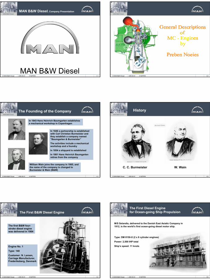
The Founding of the Company
In 1843 Hans Heinrich Baumgarten establishes a mechanical workshop in Copenhagen
In 1846 a partnership is established with Carl Christian Burmeister and they establish a company named ”Baumgarten & Burmeister”
The activities include a mechanical workshop and a foundry
In 1854 a shipyard is established
In 1861 Hans Heinrich Baumgarten retires from the company
William Wain joins the company in 1865, and the name of the company is changed to Burmeister & Wain (B&W)
2005.05.01 4140/PWN < 5>
MAN B&W Diesel
© MAN B&W Diesel
History
W. WainC. C. Burmeister
2005.05.01 4140/PWN
< 6>
MAN B&W Diesel
© MAN B&W Diesel
The First B&W Diesel Engine
The first B&W four-stroke diesel engine was delivered in 1904
Engine No. 1
Type: 140
Customer: N. Larsen, Carriage Manufacturer, Frederiksberg, Denmark
2005.05.01 4140/PWN < 8>
MAN B&W Diesel
© MAN B&W Diesel
The First Diesel Enginefor Ocean-going Ship Propulsion
M/S Selandia, delivered to the Danish East Asiatic Company in 1912, is the world’s first ocean-going diesel motor ship.
Type: DM 8150-X (2 x 8 cylinder engines)
Power: 2,500 IHP total
Ship’s speed: 11 knots
2005.05.01 4140/PWN
2
< 9>
MAN B&W Diesel
© MAN B&W Diesel
The World’s First Turbocharged Two-stroke Diesel Engine
Engine type: 674VTBF-160
Power: 7,500 BHP @ 115 r/min
M/S Dorthe Mærsk, delivered to the Danish company A. P. Møller by Odense Steel Shipyard in 1952, is the first ship to be powered by a turbocharged two-stroke diesel engine
2005.05.01 4140/PWN < 10 >
MAN B&W Diesel
© MAN B&W Diesel
Engine Development 1952 - 1980
1952: The world’s first turbocharged two-stroke engine Type: 674VTBF-160 – Power: 7,500 BHP (Introduced on M/S Dorthe Mærsk)
1967: Introduction of the K-EF range of engines, as well as thelarge K98FF type (3,800 BHP/cyl. @ 103 RPM)
1973: Delivery of the first K-GF engine
1976: The first to introduce modern long stroke diesel engines Type: L-GF, with a stroke-bore ratio of 2.5:1
1978: The first with constant pressure turbo charging of modern uniflow scavenged diesel engines
1979: The first to test a rotating air-spring on exhaust valves in service
1980: The first to introduce layout flexibility, as well as a specificfuel oil consumption below 140 g/BHPh – Type: L-GFCA
2005.05.01 4140/PWN
< 11 >
MAN B&W Diesel
© MAN B&W Diesel
In 1758 Eisenhütte St. Antony is established in Oberhausen
In 1840 Sander'sche Maschinen Fabrik is established in Augsburg
GutehoffnungshütteActienverein (GHH)is established in 1873
In 1921 GHH acquired a majority in M.A.N.
M.A.N. MaschinenfabrikAugsburg-Nürnberg(1908)
The History of MAN B&W Diesel
In 1986 M.A.N. was merged into GHH and renamed MAN AG The divisions were hived off to form individual public limited companies
In 1843 Baumgarten establishes a workshop in Copenhagen
In 1979/80 B&W Motor A/S is taken over by M.A.N., and M.A.N. B&W Diesel A/S is established
Burmeister & Wain (1865)B&W Motor A/S (1974)
2005.05.01 4140/PWN < 12 >
MAN B&W Diesel
© MAN B&W Diesel
Diesel Chronicle
1933 to introduce uniflow on a two-stroke engine1952 to introduce turbocharging on two-stroke slow speed
diesel engines1978 with constant pressure turbocharging of modern
uniflow engines1981 to demonstrate engine efficiency of more than 50%
corresponding to specific fuel oil consumption figures below125 g/BHPh
1994 to introduce an engine with power above 90,000 bhp1996 to introduce a new generation of compact engines1998 to introduce the Environmentally Friendly prop. system2000 to put an electronically controlled engine into service
The firstThe first
The first
The first
The firstThe firstThe firstThe first
2005.05.01 4140/PWN
< 13 >
MAN B&W Diesel
© MAN B&W Diesel
The MAN Group - 2005
Industrial Services
CommercialVehicles
Printing Machines Diesel Engines Turbo Machines Further IndustrialHolding*
Industrial Services Financial Services
MANNutzfahrzeuge AG
MAN RolandDruckmaschinen
AG
MAN B&W Diesel AG
MANTurbomaschinen AG
RENKAktiengesellshaft
MAN Technologie AG
MAN DWE GmbHSchwäbische
Hüttenwerke GmbH
MAN Ferrostaal AG MAN Financial Services GmbH
61,259 employeesTurnover € 14,9 billionPBT € 453 million
Turnover € 7,4 billion Turnover € 1,6 billion Turnover € 1,4 billion Turnover € 0,7 billion Turnover € 3,2 billion
2005.05.01 4140/PWN < 15 >
MAN B&W Diesel
© MAN B&W Diesel
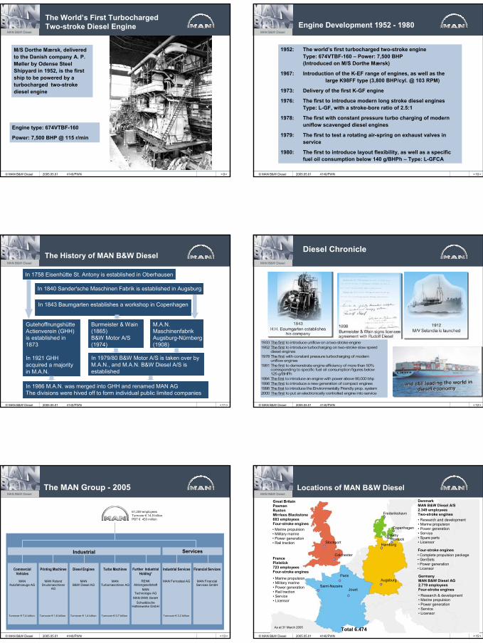
Great BritainPaxmanRustonMirrlees Blackstone683 employeesFour-stroke engines• Marine propulsion• Military marine• Power generation• Rail traction
FrancePielstick723 employeesFour-stroke engines
• Marine propulsion• Military marine• Power generation• Rail traction• Service• Licensor
DenmarkMAN B&W Diesel A/S2.349 employeesTwo-stroke engines• Research and development• Marine propulsion• Power generation• Service• Spare parts• Licensor
Four-stroke engines• Complete propulsion package• GenSets• Power generation• Licensor
GermanyMAN B&W Diesel AG2.719 employeesFour-stroke engines• Research & development• Marine propulsion• Power generation• Service• Licensor
Total 6.474As at 31 March 2005
Augsburg
Jouet
Paris
Saint-Nazaire
Colchester
Stockport Hamburg
Holeby
Copenhagen
Frederikshavn
Rostock
Locations of MAN B&W Diesel
2005.05.01 4140/PWN
3
< 16 >
MAN B&W Diesel
© MAN B&W Diesel
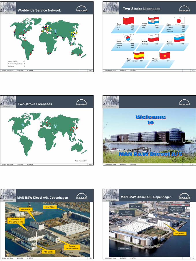
Worldwide Service Network
Service Centres 20
AuthorisednRepair Shops 55
Licensees 15
2005.05.01 4140/PWN < 17 >
MAN B&W Diesel
© MAN B&W Diesel
Two-Stroke Licensees
KoreaHyundaiDoosanSTX
PolandCegielski 1959
RussiaBryansk 1959
JapanMitsui• MakitaHitachiKawasaki
CroatiaUljanik 1954Split 1984
198019801989
1926198119511981
197619831984
ChinaHHMDMDYMD
SpainIZAR – Manises 1941
VietnamVinashin 2004
2005.05.01 4140/PWN
< 18 >
MAN B&W Diesel
© MAN B&W Diesel
Two-stroke Licensees
As at August 2004
2005.05.01 4140/PWN < 19 >
MAN B&W Diesel
© MAN B&W Diesel 2005.05.01 4140/PWN
< 20 >
MAN B&W Diesel
© MAN B&W Diesel
MAN B&W Diesel A/S, Copenhagen
2005.05.01 4140/PWN
WarehouseMain Office
Production of Key Components
R&D Centre
Factory Administration
< 21 >
MAN B&W Diesel
© MAN B&W Diesel
MAN B&W Diesel A/S, Copenhagen
Warehouse
Production of Key Components
Main Office
R&D Centre
Factory Administration
2005.05.01 4140/PWN
4
< 22 >
MAN B&W Diesel
© MAN B&W Diesel
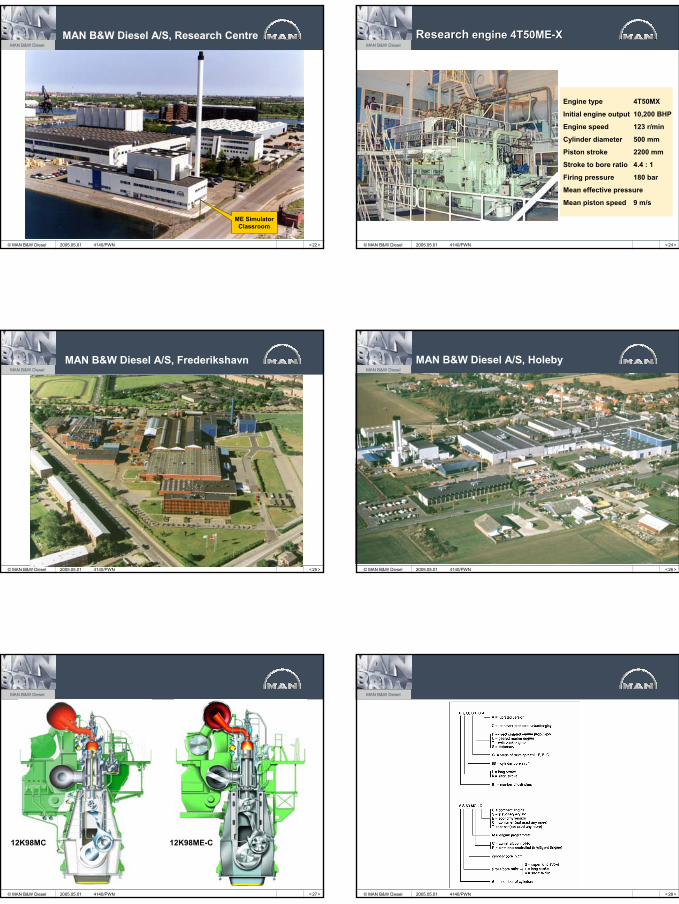
MAN B&W Diesel A/S, Research Centre
ME Simulator Classroom
2005.05.01 4140/PWN < 24 >
MAN B&W Diesel
© MAN B&W Diesel
ResearchResearch engine 4T50MEengine 4T50ME--XX
Engine type 4T50MX
Initial engine output 10,200 BHP
Engine speed 123 r/min
Cylinder diameter 500 mm
Piston stroke 2200 mm
Stroke to bore ratio 4.4 : 1
Firing pressure 180 bar
Mean effective pressure
Mean piston speed 9 m/s
2005.05.01 4140/PWN
< 25 >
MAN B&W Diesel
© MAN B&W Diesel
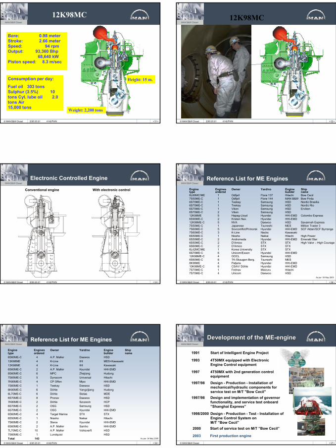
MAN B&W Diesel A/S, Frederikshavn
2005.05.01 4140/PWN < 26 >
MAN B&W Diesel
© MAN B&W Diesel
MAN B&W Diesel A/S, Holeby
2005.05.01 4140/PWN
< 27 >
MAN B&W Diesel
© MAN B&W Diesel
12K98ME-C12K98MC
2005.05.01 4140/PWN < 28 >
MAN B&W Diesel
© MAN B&W Diesel 2005.05.01 4140/PWN
5
< 31 >
MAN B&W Diesel
© MAN B&W Diesel
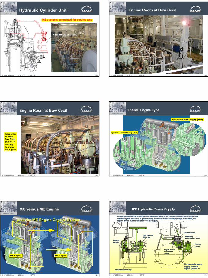
Bore: 0.98 meter Stroke: 2.66 meter Speed: 94 rpm Output: 93,360 Bhp
68,640 kW Piston speed: 8.3 m/sec
Consumption per day:
Fuel oil 303 tons Sulphur (3.5%) 10 tons Cyl. lube oil 2.0 tons Air15,000 tons
12K98MC
Weight: 2,200 tons
Height: 15 m.
2005.05.01 4140/PWN < 32 >
MAN B&W Diesel
© MAN B&W Diesel
12K98MC
2005.05.01 4140/PWN
< 34 >
MAN B&W Diesel
© MAN B&W Diesel
Electronic Controlled Engine
Conventional engine With electronic control
2005.05.01 4140/PWN < 35 >
MAN B&W Diesel
© MAN B&W Diesel
Reference List for ME EnginesEngine Engines Owner Yard/no Engine Ship type ordered builder name 6L60MC/ME 1 Odfjell Florø 137 Hitachi Bow Cecil7S50ME-C 1 Odfjell Florø 144 MAN B&W Bow Firda 6S70ME-C 1 Teekay Samsung HSD Nordic Brasilia 6S70ME-C 1 Teekay Samsung HSD Nordic Rio6S70ME-C 1 Viken Samsung HSD Erviken6S70ME-C 2 Viken Samsung HSD12K98ME 5 Hapag-Lloyd Hyundai HHI-EMD Colombo Express6S90ME-C 2 Kristen Nav. Hyundai HHI-EMD12K98ME-C 5 NVA Daewoo HSD Savannah Express7S50ME-C 1 Japanese Tsuneshi MES Million Trader 3 7S60ME-C 5 Sovcomflot/Primorsk Hyundai HHI-EMD SCF Aldan/SCF Byrranga7S60ME-C 3 K-Line Nacks Kawasaki6S50ME-C 1 Nissho Naikai Hitachi High Power6S50ME-C 2 Andromeda Hyundai HHI-EMD Emerald Star6S50ME-C 2 D’Amico STX STX High Valor – High Courage6S60ME-C 2 D’Amico STX STX6L42MC/ME 1 Korea University STX STX6S70ME-C 6 Unicom/Exxon Hyundai HHI-EMD12K98ME-C 4 OOCL Samsung HSD6S60ME-C 6 TK-Skaugen-Berg. Tsuneshi MES8K98ME 4 Patjens Hyundai HHI-EMD10K98ME-C 6 CSAV/ Döhle Hyundai HHI-EMD7S70ME-C 1 Fednav Maizuru Hitachi7S70ME-C 4 Unicom Daewoo HSD
As per 04 May 2005
2005.05.01 4140/PWN
< 36 >
MAN B&W Diesel
© MAN B&W Diesel
Reference List for ME EnginesEngine Engines Owner Yard/no Engine Ship type ordered builder name 6S60ME-C 4 A.P. Møller Daewoo HSD12K98ME 4 K-Line IHI MES+Kawasaki12K98ME 4 K-Line IHI Kawasaki6S60ME-C 2 A.P. Møller Hyundai HHI-EMD8S60ME-C 6 MPC Zhejiang Hudong7S65ME-C 5 Dynacom Universal Hitachi7K80ME-C 4 CP Offen Mipo HHI-EMD7S60ME-C 1 Teekay Daewoo HSD6K80ME-C 6 Döhle Yangzijiang Hudong6L70ME-C 6 Döhle Sietas MDE 6S70ME-C 8 Pronav Daewoo HSD7K80ME-C 2 Döhle Szczecin HCP6S70ME-C 2 OSG Samsung HSD6S70ME-C 2 OSG Hyundai HHI-EMD6S60ME-C 4 Targel Marine STX STX6S50ME-C 1 Nissho Naikai Hitachi7S60ME-C 2 Stena Hyundai HHI-EMD6S60ME-C 2 A.P. Møller Samho HHI-EMD7L70ME-C 10 A.P. Møller Volksverft HSD7S60ME-C 1 Lundquist HSDTotal 143 As per 04 May 2005
2005.05.01 4140/PWN < 37 >
MAN B&W Diesel
© MAN B&W Diesel
Development of the MEDevelopment of the ME--engineengine
1991 Start of Intelligent Engine Project
1993 4T50MX equipped with Electronic Engine Control equipment
1997 4T50MX with 2nd generation control equipment
2003 First production engine
1998/2000 Design - Production - Test - Installation of Engine Control System on M/T ”Bow Cecil”
1997/98 Design - Production - Installation of mechanical/hydraulic components for service test on M/T "Bow Cecil"
2000 Start of service test on M/T ”Bow Cecil”
1997/98 Design and implementation of governor functionality, and service test onboard ”Shanghai Express”
6
< 38 >
MAN B&W Diesel
© MAN B&W Diesel
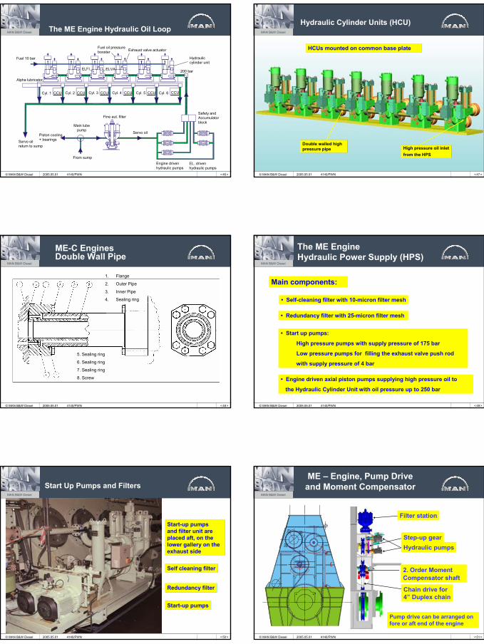
Hydraulic Cylinder Unit
ME systems connected for service test
Fuel Booster pump
2005.05.01 4140/PWN < 39 >
MAN B&W Diesel
© MAN B&W Diesel
Engine Room at Bow Cecil
2005.05.01 4140/PWN
< 40 >
MAN B&W Diesel
© MAN B&W Diesel
Engine Room at Bow Cecil
InspectiononboardBow Cecilafter 4137running hours asME engine
2005.05.01 4140/PWN < 41 >
MAN B&W Diesel
© MAN B&W Diesel
The ME Engine Type
Hydraulic Power Supply (HPS)
Hydraulic Power Supply (HPS)
2005.05.01 4140/PWN
< 42 >
MAN B&W Diesel
© MAN B&W Diesel
MC versus ME EngineMC versus ME Engine
plus the ME Engine Control Systemplus the ME Engine Control System
MC EngineMC Engine ME EngineME Engine
2005.05.01 4140/PWN < 45 >
MAN B&W Diesel
© MAN B&W Diesel
x
HPS Hydraulic Power Supply
Start-uppumpsStart-uppumps
Self cleaningfilter 10µSelf cleaningfilter 10µ
Redundancy filter 25µRedundancy filter 25µ
Safety andaccumulators blockSafety andaccumulators block
Start-uppumpsStart-uppumps
AccumulatorsAccumulators
Engine driven axial pistonpumps
Engine driven axial pistonpumps
Before engine start, the hydraulic oil pressure used in the mechanical/hydraulic system for controlling the actuators is generated by electrical driven start-up pumps. After start, the engine driven pumps will take over the supply.
Before engine start, the hydraulic oil pressure used in the mechBefore engine start, the hydraulic oil pressure used in the mechanical/hydraulic system for anical/hydraulic system for controlling the actuators is generated by electrical driven starcontrolling the actuators is generated by electrical driven startt--up pumps. After start, the up pumps. After start, the engine driven pumps will take over the supply.engine driven pumps will take over the supply.
The hydraulic power supply uses the engine system oil
The hydraulic power The hydraulic power supply uses the supply uses the engine system oilengine system oil
2005.05.01 4140/PWN
7
< 46 >
MAN B&W Diesel
© MAN B&W Diesel
The ME Engine Hydraulic Oil Loop
Fuel 10 bar Hydrauliccylinder unit
Alpha lubricator
Servo oilreturn to sump
Fine aut. filter
Piston cooling + bearings
From sump
Main lubepump
Safety and Accumulatorblock
EL. driven hydraulic pumps
Engine drivenhydraulic pumps
Servo oil
Fuel oil pressurebooster Exhaust valve actuator
ELFI ELVA
Cyl. 1 Cyl. 2 Cyl. 3 Cyl. 4 Cyl. 5 Cyl. 6CCUCCU CCU CCU CCU CCU
200 bar
2005.05.01 4140/PWN < 47 >
MAN B&W Diesel
© MAN B&W Diesel
Hydraulic Cylinder Units (HCU)
High pressure oil inletfrom the HPSHigh pressure oil inletfrom the HPS
Double walled high pressure pipeDouble walled high pressure pipe
HCUs mounted on common base plateHCUs mounted on common base plate
2005.05.01 4140/PWN
< 48 >
MAN B&W Diesel
© MAN B&W Diesel
ME-C EnginesDouble Wall Pipe
1. Flange
2. Outer Pipe
3. Inner Pipe
4. Sealing ring
5. Sealing ring
6. Sealing ring
7. Sealing ring
8. Screw
2005.05.01 4140/PWN < 49 >
MAN B&W Diesel
© MAN B&W Diesel
The ME EngineHydraulic Power Supply (HPS)
Main components:
• Self-cleaning filter with 10-micron filter mesh
• Redundancy filter with 25-micron filter mesh
• Start up pumps:
High pressure pumps with supply pressure of 175 bar
Low pressure pumps for filling the exhaust valve push rod
with supply pressure of 4 bar
• Engine driven axial piston pumps supplying high pressure oil to
the Hydraulic Cylinder Unit with oil pressure up to 250 bar
2005.05.01 4140/PWN
< 50 >
MAN B&W Diesel
© MAN B&W Diesel
Start Up Pumps and Filters
Start-up pumps and filter unit are placed aft, on the lower gallery on the exhaust side
Start-up pumps and filter unit are placed aft, on the lower gallery on the exhaust side
Self cleaning filterSelf cleaning filter
Redundancy filterRedundancy filter
Start-up pumpsStart-up pumps
2005.05.01 4140/PWN < 51 >
MAN B&W Diesel
© MAN B&W Diesel
ME – Engine, Pump Drive and Moment Compensator
Filter station
Step-up gearHydraulic pumps
2. Order Moment Compensator shaft
Chain drive for 4” Duplex chain
Pump drive can be arranged on fore or aft end of the engine
2005.05.01 4140/PWN
8
< 52 >
MAN B&W Diesel
© MAN B&W Diesel
Hydraulic Cylinder Unit
Hydraulic ExhaustValve Actuator
ELVAOn/Off Valve
Distribution Block
Fuel oil Pressure Booster
ELFIProportional Valve
2005.05.01 4140/PWN < 53 >
MAN B&W Diesel
© MAN B&W Diesel
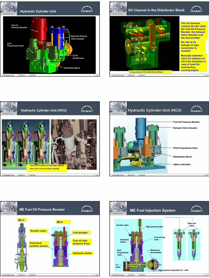
Oil Channel in the Distributor Block
The oil channels connect the NC-valve, the Fuel Oil Pressure Booster, the Exhaust Valve Actuator and the Accumulator
The oil channels connect the NC-valve, the Fuel Oil Pressure Booster, the Exhaust Valve Actuator and the Accumulator
X-ray picture of the Distributor BlockX-ray picture of the Distributor Block
No risk of oil leakage as pipe connection is avoided
No risk of oil leakage as pipe connection is avoided
Manually operated valve for isolation of oil to the actuators in case of need for overhauling –running engine
Manually operated valve for isolation of oil to the actuators in case of need for overhauling –running engine
2005.05.01 4140/PWN
< 54 >
MAN B&W Diesel
© MAN B&W Diesel
Hydraulic Cylinder Unit (HCU)
The HCU is found on the upper gallery One unit in front of each cylinder
The HCU is found on the upper gallery One unit in front of each cylinder
2005.05.01 4140/PWN < 55 >
MAN B&W Diesel
© MAN B&W Diesel
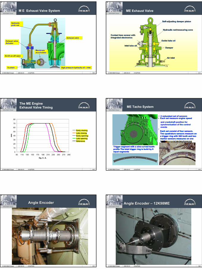
Hydraulic Cylinder Unit (HCU)Hydraulic Cylinder Unit (HCU)
FIVA Proportional ValveFIVA Proportional Valve
Distribution BlockDistribution Block
Exhaust Valve Actuator Exhaust Valve Actuator
Fuel Oil Pressure BoosterFuel Oil Pressure Booster
Alpha Lubricator Alpha Lubricator
2005.05.01 4140/PWN
< 56 >
MAN B&W Diesel
© MAN B&W Diesel
ME Fuel Oil Pressure Booster
MC-CMC-CME-CME-C
Fuel plungerFuel plunger
Hydraulic pistonHydraulic piston
Fuel oil inlet pressure 8 barFuel oil inlet pressure 8 barFeed back
position sensorFeed back position sensor
Suction valveSuction valve
2005.05.01 4140/PWN < 57 >
MAN B&W Diesel
© MAN B&W Diesel
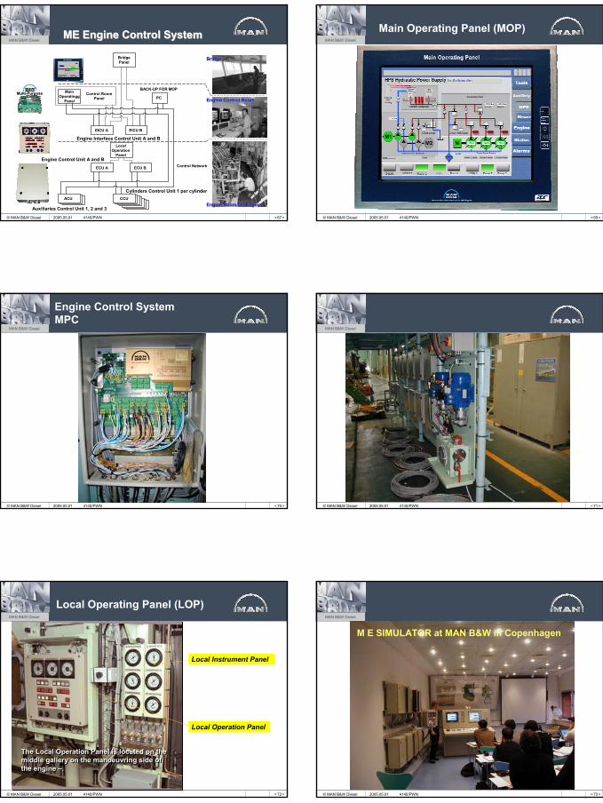
ME Fuel Injection System
To drainTo drain
MembraneaccumulatorMembraneaccumulator
Fuel oil inlet 8 barFuel oil inlet 8 bar
Suction valveSuction valve
ELFI Proportional valve
ELFI Proportional valve
Slide fuel valve
Slide fuel valve
Hydraulic pistonHydraulic piston
High pressure pipeHigh pressure pipe
High pressure hydraulic oil – inletHigh pressure hydraulic oil – inlet
2005.05.01 4140/PWN
9
< 59 >
MAN B&W Diesel
© MAN B&W Diesel
M E Exhaust Valve System
ELVA on-off valveELVA on-off valve
Exhaust valve ActuatorExhaust valve Actuator
Exhaust valveExhaust valve
To drainTo drain High pressure hydraulic oil – inletHigh pressure hydraulic oil – inlet
MembraneaccumulatorMembraneaccumulator
Hydraulicpush rodHydraulicpush rod
2005.05.01 4140/PWN < 61 >
MAN B&W Diesel
© MAN B&W Diesel
ME Exhaust Valve
Self-adjusting damper pistonSelf-adjusting damper piston
Hydraulic nut/measuring coneHydraulic nut/measuring cone
Outlet lube oilOutlet lube oil
DamperDamper
Air inletAir inlet
Inlet lube oilInlet lube oil
Contact less sensor with integrated electronicsContact less sensor with integrated electronics
2005.05.01 4140/PWN
< 62 >
MAN B&W Diesel
© MAN B&W Diesel
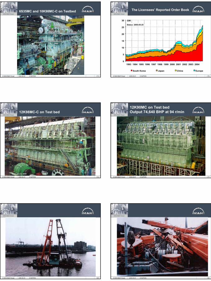
The ME EngineExhaust Valve Timing
0
10
20
30
40
50
60
70
80
90 110 130 150 170 190 210 230 250 270 290
Dg. C. A.
mm
Early closingLate closingEarly openingLate openingReference
2005.05.01 4140/PWN < 64 >
MAN B&W Diesel
© MAN B&W Diesel
ME Tacho System
Trigger segment with a sine-curved tooth-profile The total trigger ring is build by 8 equal segments
Trigger segment with a sine-curved tooth-profile The total trigger ring is build by 8 equal segments
• 2 redundant set of sensors• 2 redundant set of sensors
Each set consist of four sensors. Two quadrature sensors measure on a trigger ring with 360 tooth and two marker sensors measures on one tooth – a semicircular ring
Each set consist of four sensors. Two quadrature sensors measure on a trigger ring with 360 tooth and two marker sensors measures on one tooth – a semicircular ring
• Each set measure engine speed• Each set measure engine speed
••
and crankshaft position for synchronisation of the control events
and crankshaft position for synchronisation of the control events
2005.05.01 4140/PWN
< 65 >
MAN B&W Diesel
© MAN B&W Diesel 2005.05.01 4140/PWN
Angle EncoderAngle Encoder
< 66 >
MAN B&W Diesel
© MAN B&W Diesel
Angle Encoder Angle Encoder –– 12K98ME12K98ME
2005.05.01 4140/PWN
10
< 67 >
MAN B&W Diesel
© MAN B&W Diesel
BridgeBridge
Engine Control RoomEngine Control Room
Engine Room/On EngineEngine Room/On Engine
MainOperatingg
PanelPC
Control RoomPanel
BACK-UP FOR MOP
BridgePanel
ACU CCU
ECU A
EICU A
Auxiliaries Control Unit 1, 2 and 3
Engine Interface Control Unit A and B
ECU B
Cylinders Control Unit 1 per cylinder
EICU B
Engine Control Unit A and B
LocalOperation
Panel
Control Network
ME ME Engine Control SystemEngine Control System
2005.05.01 4140/PWN
MultiMulti--Purpose Purpose ControllerController
< 69 >
MAN B&W Diesel
© MAN B&W Diesel
Main Operating Panel (MOP)
2005.05.01 4140/PWN
< 70 >
MAN B&W Diesel
© MAN B&W Diesel
Engine Control SystemMPC
2005.05.01 4140/PWN < 71 >
MAN B&W Diesel
© MAN B&W Diesel 2005.05.01 4140/PWN
< 72 >
MAN B&W Diesel
© MAN B&W Diesel
Local Operating Panel (LOP)
The Local Operation Panel is located on the middle gallery on the manoeuvring side of the engine –.
The Local Operation Panel is located on the middle gallery on the manoeuvring side of the engine –.
Local Instrument Panel
Local Operation Panel
2005.05.01 4140/PWN < 73 >
MAN B&W Diesel
© MAN B&W Diesel
M E SIMULATOR at MAN B&W in Copenhagen
2005.05.01 4140/PWN
11
< 74 >
MAN B&W Diesel
© MAN B&W Diesel
6S35MC and 10K98MC-C on Testbed
2005.05.01 4140/PWN < 75 >
MAN B&W Diesel
© MAN B&W Diesel
0
5
10
15
20
25
30
1993 1994 1995 1996 1997 1998 1999 2000 2001 2002 2003 2004
South Korea Japan China Europe
GW
Status: 2005-05-25
The Licensees’ Reported Order Book
2005.05.01 4140/PWN
< 76 >
MAN B&W Diesel
© MAN B&W Diesel
12K98MC-C on Test bed
As at January 2000
2005.05.01 4140/PWN < 77 >
MAN B&W Diesel
© MAN B&W Diesel
12K90MC on Test bedOutput 74,640 BHP at 94 r/min
2005.05.01 4140/PWN
< 88 >
MAN B&W Diesel
© MAN B&W Diesel 2005.05.01 4140/PWN < 89 >
MAN B&W Diesel
© MAN B&W Diesel 2005.05.01 4140/PWN
12
< 90 >
MAN B&W Diesel
© MAN B&W Diesel 2005.05.01 4140/PWN < 91 >
MAN B&W Diesel
© MAN B&W Diesel 2005.05.01 4140/PWN
< 92 >
MAN B&W Diesel
© MAN B&W Diesel
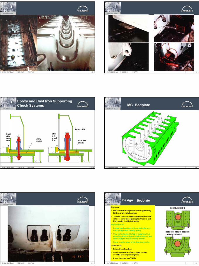
Epoxy and Cast Iron Supporting Chock Systems
Steelsidechockliner
Epoxychocks
Steel sidechockliner
Taper 1:100
Cast ironchocks
2005.05.01 4140/PWN < 93 >
MAN B&W Diesel
© MAN B&W Diesel
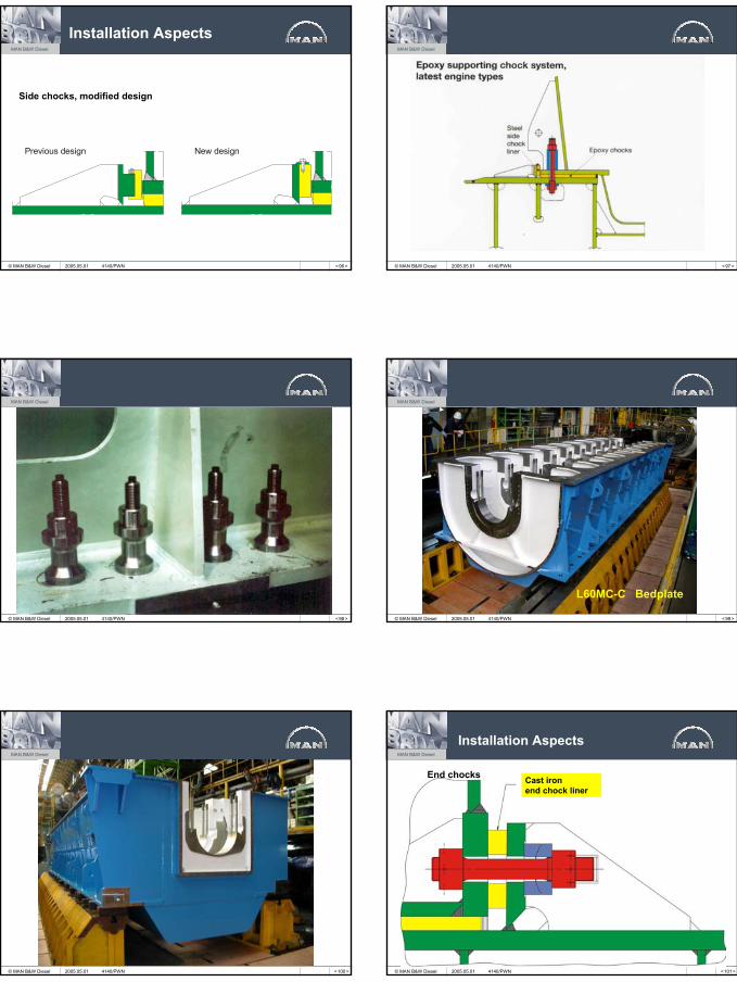
MC Bedplate
2005.05.01 4140/PWN
< 94 >
MAN B&W Diesel
© MAN B&W Diesel 2005.05.01 4140/PWN < 95 >
MAN B&W Diesel
© MAN B&W Diesel
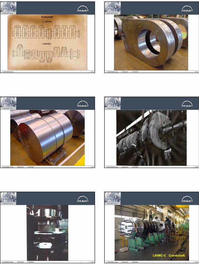
Design
Features:
Well defined and rigid main bearing housing for thin shell main bearings
Transfer of forces to holding-down bolts and cylinder cover through simple structure and high quality double butt welds
Improvements:
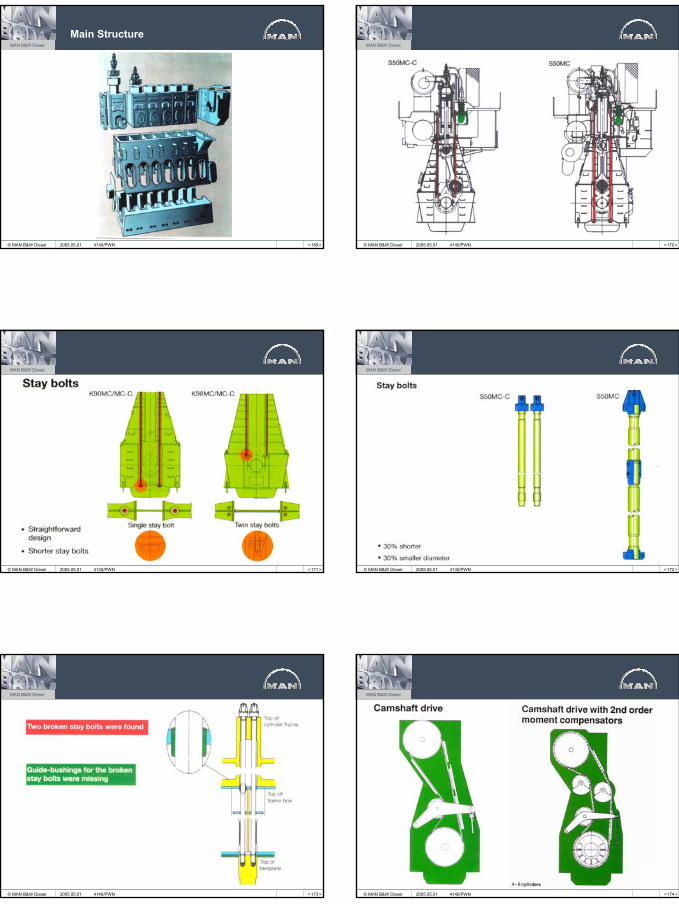
Simple steel castings without holes for stay bolt, giving better casting quality
Stay bolts attached to top of bedplate, thus reducing deformation of bearing housing and eliminating fretting in bearing saddle
Easier maintenance of holding-down bolts.
Verification:
Extensive calculation
Service experience from a large number of S-MC-C "compact" engines
6 years service on 4T50MX
Bedplate
K90MC, K90MC-C
K98MC-C, K98MC, S90MC-CL90MC-C, S80MC-C
2005.05.01 4140/PWN
13
< 96 >
MAN B&W Diesel
© MAN B&W Diesel
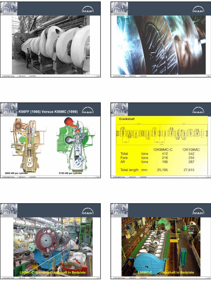
Installation Aspects
Previous design New design
Side chocks, modified design
2005.05.01 4140/PWN < 97 >
MAN B&W Diesel
© MAN B&W Diesel 2005.05.01 4140/PWN
< 98 >
MAN B&W Diesel
© MAN B&W Diesel 2005.05.01 4140/PWN < 99 >
MAN B&W Diesel
© MAN B&W Diesel
L60MC-C Bedplate
2005.05.01 4140/PWN
< 100 >
MAN B&W Diesel
© MAN B&W Diesel 2005.05.01 4140/PWN < 101 >
MAN B&W Diesel
© MAN B&W Diesel
Installation Aspects
End chocks Cast ironend chock liner
2005.05.01 4140/PWN
14
< 102 >
MAN B&W Diesel
© MAN B&W Diesel < 103 >
MAN B&W Diesel
© MAN B&W Diesel 2005.05.01 4140/PWN
< 104 >
MAN B&W Diesel
© MAN B&W Diesel 2005.05.01 4140/PWN < 105 >
MAN B&W Diesel
© MAN B&W Diesel 2005.05.01 4140/PWN
< 106 >
MAN B&W Diesel
© MAN B&W Diesel 2005.05.01 4140/PWN < 107 >
MAN B&W Diesel
© MAN B&W Diesel
L60MC-C Crankshaft.
2005.05.01 4140/PWN
15
< 108 >
MAN B&W Diesel
© MAN B&W Diesel 2005.05.01 4140/PWN < 109 >
MAN B&W Diesel
© MAN B&W Diesel 2005.05.01 4140/PWN
< 110 >
MAN B&W Diesel
© MAN B&W Diesel
K98FF (1966) Versus K98MC (1999)
2800 kW per cylinder 5720 kW per cylinder2005.05.01 4140/PWN < 111 >
MAN B&W Diesel
© MAN B&W Diesel 2005.05.01 4140/PWN
< 112 >
MAN B&W Diesel
© MAN B&W Diesel
L60MC-C Landing Crankshaft in Bedplate2005.05.01 4140/PWN < 113 >
MAN B&W Diesel
© MAN B&W Diesel
L60MC-C Crankshaft in Bedplate2005.05.01 4140/PWN
16
< 114 >
MAN B&W Diesel
© MAN B&W Diesel 2005.05.01 4140/PWN < 115 >
MAN B&W Diesel
© MAN B&W Diesel 2005.05.01 4140/PWN
< 116 >
MAN B&W Diesel
© MAN B&W Diesel 2005.05.01 4140/PWN < 117 >
MAN B&W Diesel
© MAN B&W Diesel 2005.05.01 4140/PWN
< 118 >
MAN B&W Diesel
© MAN B&W Diesel 2005.05.01 4140/PWN < 120 >
MAN B&W Diesel
© MAN B&W Diesel 2005.05.01 4140/PWN
17
< 121 >
MAN B&W Diesel
© MAN B&W Diesel 2005.05.01 4140/PWN < 122 >
MAN B&W Diesel
© MAN B&W Diesel 2005.05.01 4140/PWN
< 123 >
MAN B&W Diesel
© MAN B&W Diesel
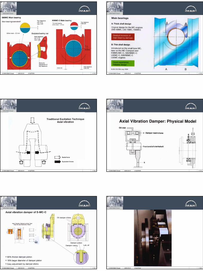
Earthing deviceCurrent
Steel:= ÷
Bronze: Propeller = +
Main bearing
Potential difference< 50 mV
HullIntermediate shaftPropeller shaft
Spark erosion in main bearings
V
Earthing Device
2005.05.01 4140/PWN < 125 >
MAN B&W Diesel
© MAN B&W Diesel 2005.05.01 4140/PWN
< 126 >
MAN B&W Diesel
© MAN B&W Diesel 2005.05.01 4140/PWN < 127 >
MAN B&W Diesel
© MAN B&W Diesel
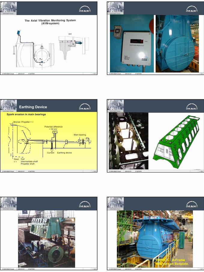
L60MC-C A-Frame Mounted on Bedplate.
2005.05.01 4140/PWN
18
< 128 >
MAN B&W Diesel
© MAN B&W Diesel 2005.05.01 4140/PWN < 129 >
MAN B&W Diesel
© MAN B&W Diesel 2005.05.01 4140/PWN
< 130 >
MAN B&W Diesel
© MAN B&W Diesel 2005.05.01 4140/PWN < 131 >
MAN B&W Diesel
© MAN B&W Diesel 2005.05.01 4140/PWN
< 132 >
MAN B&W Diesel
© MAN B&W Diesel 2005.05.01 4140/PWN < 134 >
MAN B&W Diesel
© MAN B&W Diesel 2005.05.01 4140/PWN
19
< 136 >
MAN B&W Diesel
© MAN B&W Diesel 2005.05.01 4140/PWN < 137 >
MAN B&W Diesel
© MAN B&W Diesel 2005.05.01 4140/PWN
< 138 >
MAN B&W Diesel
© MAN B&W Diesel 2005.05.01 4140/PWN < 139 >
MAN B&W Diesel
© MAN B&W Diesel 2005.05.01 4140/PWN
< 140 >
MAN B&W Diesel
© MAN B&W Diesel 2005.05.01 4140/PWN < 141 >
MAN B&W Diesel
© MAN B&W Diesel
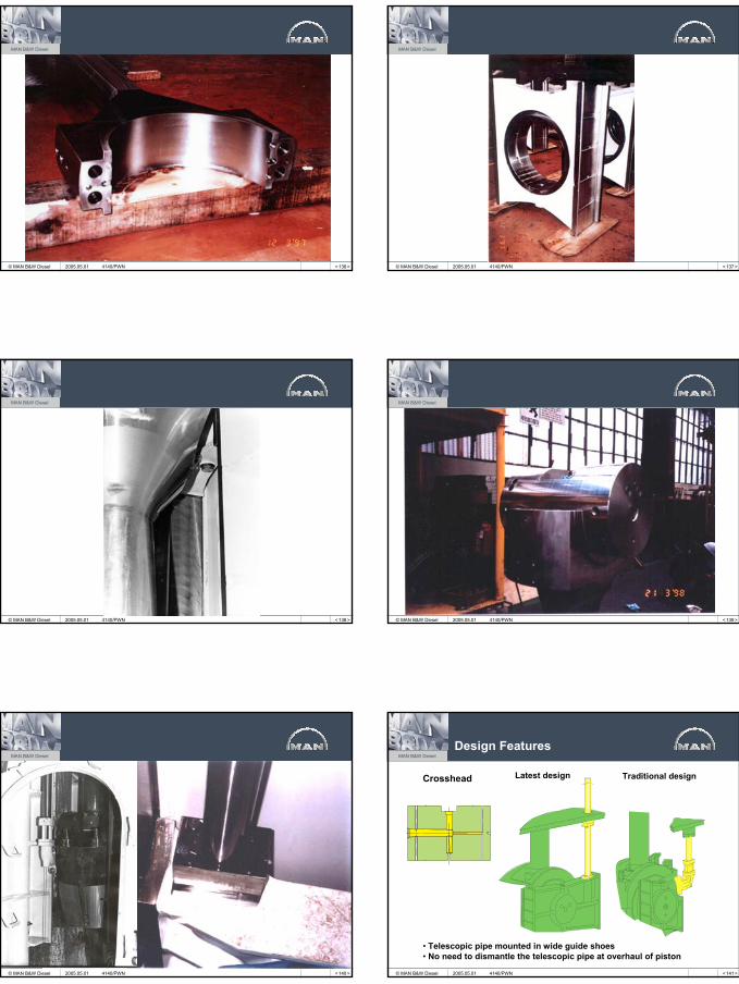
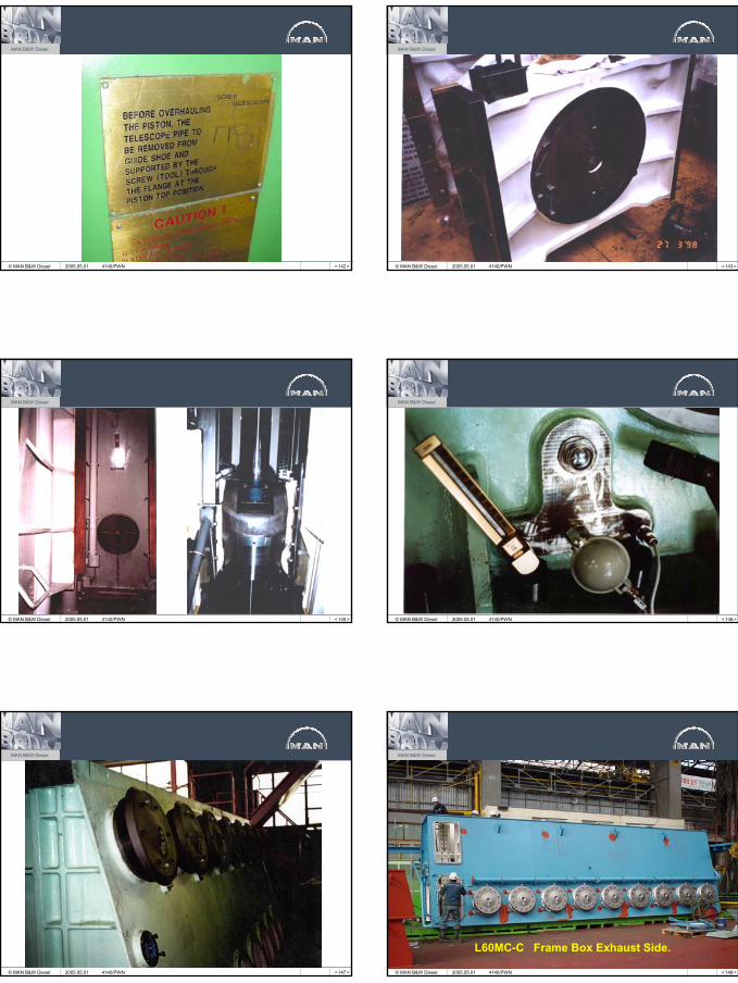
• Telescopic pipe mounted in wide guide shoes• No need to dismantle the telescopic pipe at overhaul of piston
Crosshead Traditional designLatest design
Design Features
2005.05.01 4140/PWN
20
< 142 >
MAN B&W Diesel
© MAN B&W Diesel 2005.05.01 4140/PWN < 143 >
MAN B&W Diesel
© MAN B&W Diesel 2005.05.01 4140/PWN
< 145 >
MAN B&W Diesel
© MAN B&W Diesel 2005.05.01 4140/PWN < 146 >
MAN B&W Diesel
© MAN B&W Diesel 2005.05.01 4140/PWN
< 147 >
MAN B&W Diesel
© MAN B&W Diesel 2005.05.01 4140/PWN < 148 >
MAN B&W Diesel
© MAN B&W Diesel
L60MC-C Frame Box Exhaust Side.
2005.05.01 4140/PWN
21
< 149 >
MAN B&W Diesel
© MAN B&W Diesel 2005.05.01 4140/PWN < 150 >
MAN B&W Diesel
© MAN B&W Diesel 2005.05.01 4140/PWN
< 151 >
MAN B&W Diesel
© MAN B&W Diesel
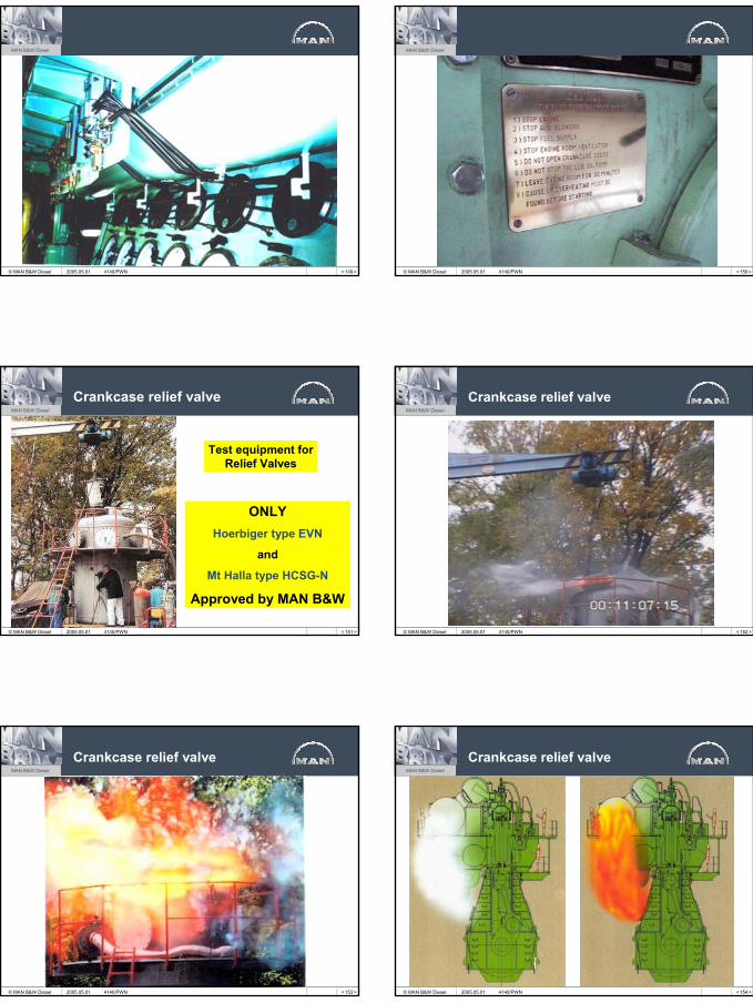
Test equipment for Relief Valves
ONLYHoerbiger type EVN
and
Mt Halla type HCSG-N
Approved by MAN B&W
Crankcase relief valve
2005.05.01 4140/PWN < 152 >
MAN B&W Diesel
© MAN B&W Diesel
Crankcase relief valve
2005.05.01 4140/PWN
< 153 >
MAN B&W Diesel
© MAN B&W Diesel
Crankcase relief valve
2005.05.01 4140/PWN < 154 >
MAN B&W Diesel
© MAN B&W Diesel
Crankcase relief valve
2005.05.01 4140/PWN
22
< 156 >
MAN B&W Diesel
© MAN B&W Diesel
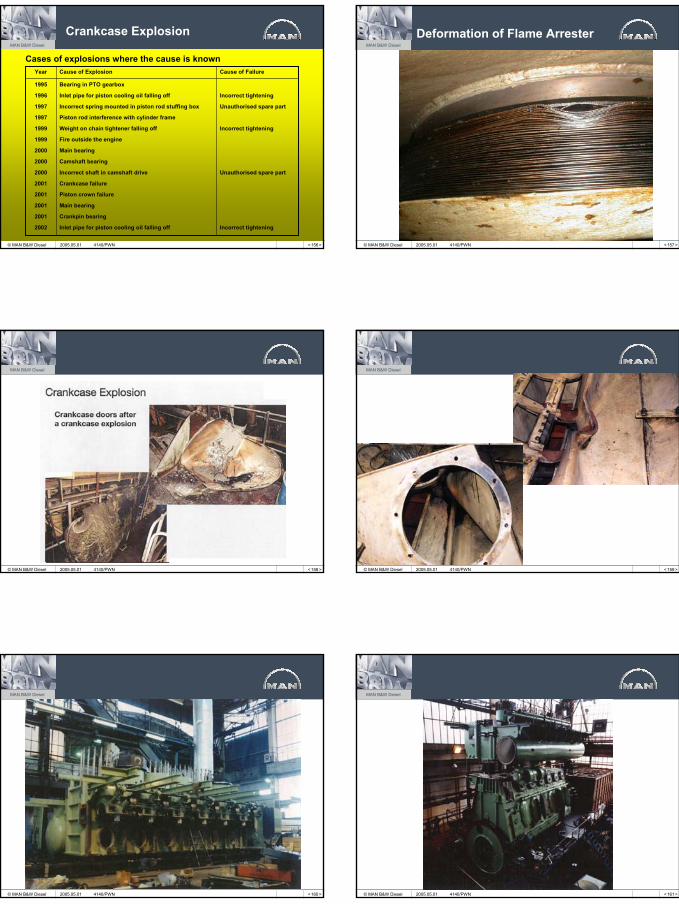
Crankcase Explosion
Cases of explosions where the cause is known
Incorrect tightening
Unauthorised spare part
Incorrect tightening
Unauthorised spare part
Incorrect tightening
Bearing in PTO gearbox
Inlet pipe for piston cooling oil falling off
Incorrect spring mounted in piston rod stuffing box
Piston rod interference with cylinder frame
Weight on chain tightener falling off
Fire outside the engine
Main bearing
Camshaft bearing
Incorrect shaft in camshaft drive
Crankcase failure
Piston crown failure
Main bearing
Crankpin bearing
Inlet pipe for piston cooling oil falling off
1995
1996
1997
1997
1999
1999
2000
2000
2000
2001
2001
2001
2001
2002
Cause of FailureCause of ExplosionYear
2005.05.01 4140/PWN < 157 >
MAN B&W Diesel
© MAN B&W Diesel
Deformation of Flame Arrester
2005.05.01 4140/PWN
< 158 >
MAN B&W Diesel
© MAN B&W Diesel 2005.05.01 4140/PWN < 159 >
MAN B&W Diesel
© MAN B&W Diesel 2005.05.01 4140/PWN
< 160 >
MAN B&W Diesel
© MAN B&W Diesel 2005.05.01 4140/PWN < 161 >
MAN B&W Diesel
© MAN B&W Diesel 2005.05.01 4140/PWN
23
< 162 >
MAN B&W Diesel
© MAN B&W Diesel 2005.05.01 4140/PWN < 163 >
MAN B&W Diesel
© MAN B&W Diesel
Simplification of Cylinder Frame
Previous design New design
Cooling water inlet
Cooling water inlet
2005.05.01 4140/PWN
< 164 >
MAN B&W Diesel
© MAN B&W Diesel < 165 >
MAN B&W Diesel
© MAN B&W Diesel 2005.05.01 4140/PWN
< 167 >
MAN B&W Diesel
© MAN B&W Diesel
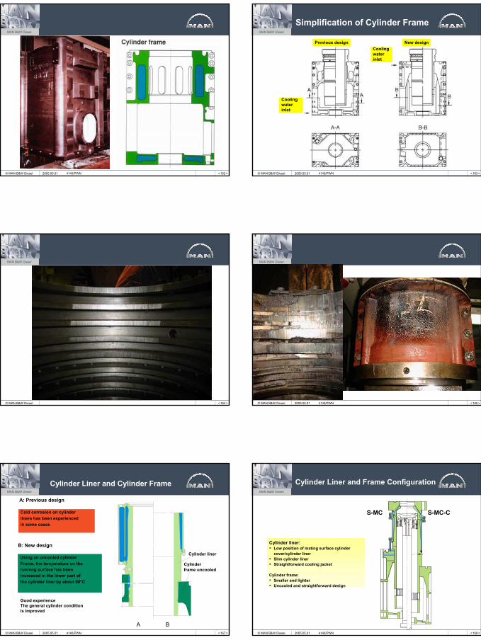
A: Previous design
Cold corrosion on cylinder liners has been experienced in some cases
B: New design
Good experienceThe general cylinder conditionis improved
Using an uncooled cylinder Frame, the temperature on the running surface has been increased in the lower part of the cylinder liner by about 60°C
Cylinder liner
Cylinderframe uncooled
A B
Cylinder Liner and Cylinder Frame
2005.05.01 4140/PWN < 168 >
MAN B&W Diesel
© MAN B&W Diesel
S-MC-CS-MC
Cylinder Liner and Frame Configuration
Cylinder liner:Low position of mating surface cylinder cover/cylinder linerSlim cylinder linerStraightforward cooling jacket
Cylinder frame:Smaller and lighterUncooled and straightforward design
2005.05.01 4140/PWN
24
< 169 >
MAN B&W Diesel
© MAN B&W Diesel
Main Structure
2005.05.01 4140/PWN < 170 >
MAN B&W Diesel
© MAN B&W Diesel 2005.05.01 4140/PWN
< 171 >
MAN B&W Diesel
© MAN B&W Diesel 2005.05.01 4140/PWN < 172 >
MAN B&W Diesel
© MAN B&W Diesel 2005.05.01 4140/PWN
< 173 >
MAN B&W Diesel
© MAN B&W Diesel 2005.05.01 4140/PWN < 174 >
MAN B&W Diesel
© MAN B&W Diesel 2005.05.01 4140/PWN
25
< 175 >
MAN B&W Diesel
© MAN B&W Diesel
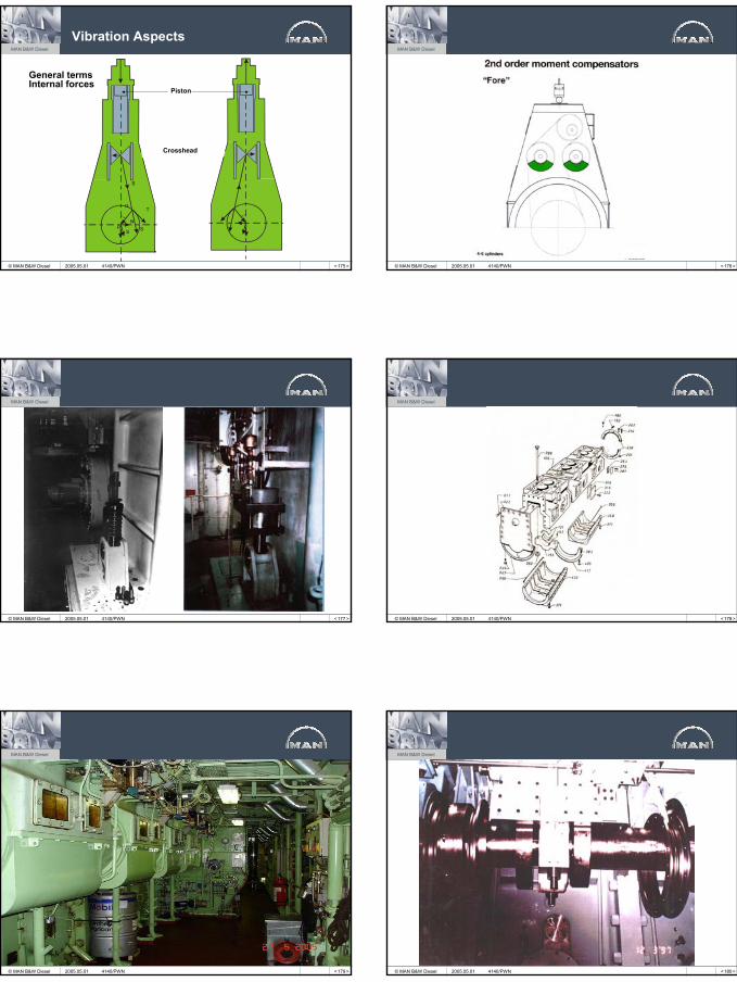
Vibration Aspects
General termsInternal forces
Piston
T
NP
S S
S
Crosshead
α
2005.05.01 4140/PWN < 176 >
MAN B&W Diesel
© MAN B&W Diesel 2005.05.01 4140/PWN
< 177 >
MAN B&W Diesel
© MAN B&W Diesel 2005.05.01 4140/PWN < 178 >
MAN B&W Diesel
© MAN B&W Diesel 2005.05.01 4140/PWN
< 179 >
MAN B&W Diesel
© MAN B&W Diesel 2005.05.01 4140/PWN < 180 >
MAN B&W Diesel
© MAN B&W Diesel 2005.05.01 4140/PWN
26
< 181 >
MAN B&W Diesel
© MAN B&W Diesel 2005.05.01 4140/PWN < 182 >
MAN B&W Diesel
© MAN B&W Diesel 2005.05.01 4140/PWN
< 183 >
MAN B&W Diesel
© MAN B&W Diesel 2005.05.01 4140/PWN < 184 >
MAN B&W Diesel
© MAN B&W Diesel 2005.05.01 4140/PWN
< 185 >
MAN B&W Diesel
© MAN B&W Diesel
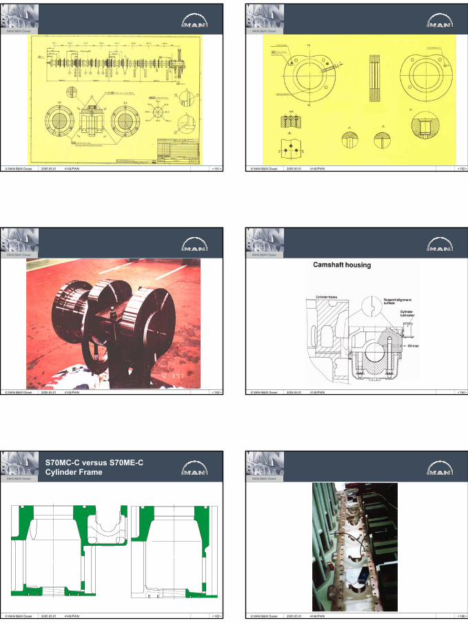
S70MC-C versus S70ME-C Cylinder Frame
2005.05.01 4140/PWN < 186 >
MAN B&W Diesel
© MAN B&W Diesel 2005.05.01 4140/PWN
27
< 187 >
MAN B&W Diesel
© MAN B&W Diesel
L60MC-C Camshaft
2005.05.01 4140/PWN < 188 >
MAN B&W Diesel
© MAN B&W Diesel
L60MC-C Top Cover for Camshaft Housing
2005.05.01 4140/PWN
< 191 >
MAN B&W Diesel
© MAN B&W Diesel 2005.05.01 4140/PWN < 192 >
MAN B&W Diesel
© MAN B&W Diesel 2005.05.01 4140/PWN
< 193 >
MAN B&W Diesel
© MAN B&W Diesel
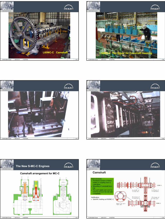
Camshaft arrangement for MC-C
The New S-MC-C Engines
2005.05.01 4140/PWN < 194 >
MAN B&W Diesel
© MAN B&W Diesel 2005.05.01 4140/PWN
28
< 195 >
MAN B&W Diesel
© MAN B&W Diesel 2005.05.01 4140/PWN < 196 >
MAN B&W Diesel
© MAN B&W Diesel 2005.05.01 4140/PWN
< 199 >
MAN B&W Diesel
© MAN B&W Diesel 2005.05.01 4140/PWN < 200 >
MAN B&W Diesel
© MAN B&W Diesel 2005.05.01 4140/PWN
< 201 >
MAN B&W Diesel
© MAN B&W Diesel 2005.05.01 4140/PWN < 202 >
MAN B&W Diesel
© MAN B&W Diesel 2005.05.01 4140/PWN
29
< 203 >
MAN B&W Diesel
© MAN B&W Diesel 2005.05.01 4140/PWN < 205 >
MAN B&W Diesel
© MAN B&W Diesel 2005.05.01 4140/PWN
< 206 >
MAN B&W Diesel
© MAN B&W Diesel
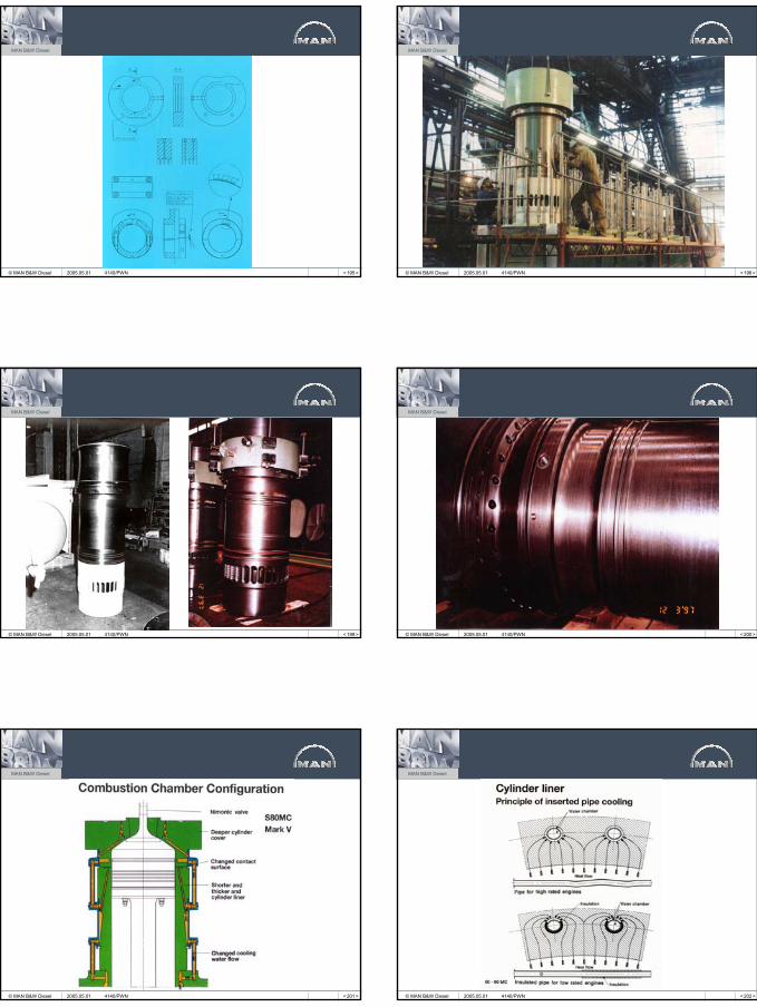
Alpha Lubricator System
Solenoid valve - activated
Alpha lubricator
Injection plungers
Spacer for basic settingof pump stroke
Actuator pistonAdjusting screw
Signal for lubrication from control unit
Solenoid valve
Inductive feed-backsensor for control of
piston movement
Cylinder lubeoil outlet
Cylinderlube oil inlet
2005.05.01 4140/PWN < 207 >
MAN B&W Diesel
© MAN B&W Diesel
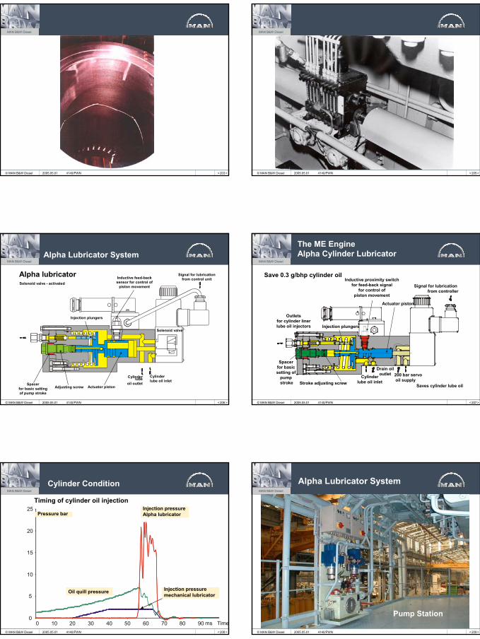
The ME EngineAlpha Cylinder Lubricator
Spacer for basic setting of
pump stroke Stroke adjusting screw
Cylinderlube oil inlet
200 bar servooil supply
Signal for lubrication from controller
Inductive proximity switchfor feed-back signal
for control ofpiston movement
Injection plungers
Actuator piston
Drain oiloutlet
Outletsfor cylinder linerlube oil injectors
Saves cylinder lube oil
Save 0.3 g/bhp cylinder oil
2005.05.01 4140/PWN
< 208 >
MAN B&W Diesel
© MAN B&W Diesel
0
5
10
15
20
25
10 20 30 40 50 60 70 80 90 ms Time0
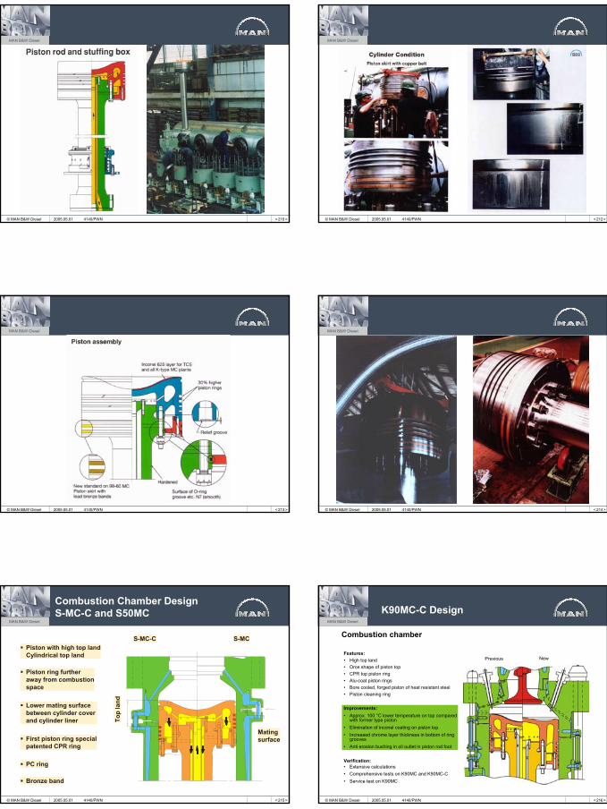
Cylinder Condition
Timing of cylinder oil injectionInjection pressureAlpha lubricator
Injection pressuremechanical lubricator
Oil quill pressure
Pressure bar
2005.05.01 4140/PWN < 209 >
MAN B&W Diesel
© MAN B&W Diesel
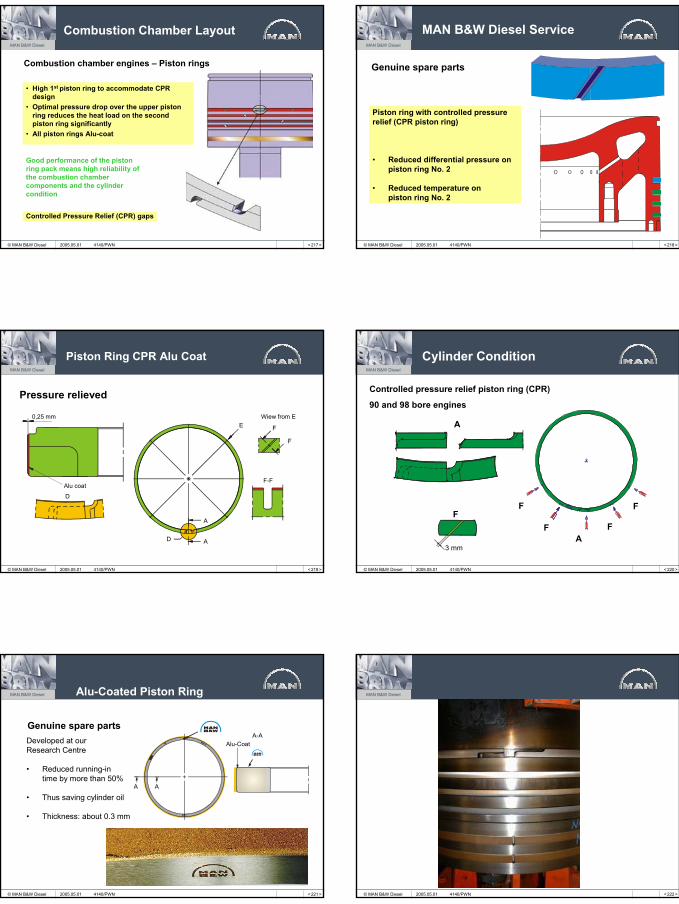
Pump Station
Alpha Lubricator System
2005.05.01 4140/PWN
30
< 210 >
MAN B&W Diesel
© MAN B&W Diesel 2005.05.01 4140/PWN < 212 >
MAN B&W Diesel
© MAN B&W Diesel 2005.05.01 4140/PWN
< 213 >
MAN B&W Diesel
© MAN B&W Diesel 2005.05.01 4140/PWN < 214 >
MAN B&W Diesel
© MAN B&W Diesel 2005.05.01 4140/PWN
< 215 >
MAN B&W Diesel
© MAN B&W Diesel
Combustion Chamber DesignS-MC-C and S50MC
Piston with high top landCylindrical top land
Piston ring further away from combustionspace
Lower mating surface between cylinder cover and cylinder liner
First piston ring specialpatented CPR ring
PC ring
Bronze band
Top
land
S-MC-C S-MC
Matingsurface
2005.05.01 4140/PWN < 216 >
MAN B&W Diesel
© MAN B&W Diesel
K90MC-C Design
Combustion chamber
Previous NewFeatures:• High top land• Oros shape of piston top• CPR top piston ring• Alu-coat piston rings• Bore cooled, forged piston of heat resistant steel• Piston cleaning ring
Improvements:• Approx. 100 °C lower temperature on top compared
with former type piston• Elimination of inconel coating on piston top• Increased chrome layer thickness in bottom of ring
grooves• Anti erosion bushing in oil outlet in piston rod foot
Verification:• Extensive calculations• Comprehensive tests on K90MC and K90MC-C • Service test on K90MC
2005.05.01 4140/PWN
31
< 217 >
MAN B&W Diesel
© MAN B&W Diesel
Combustion Chamber Layout
• High 1st piston ring to accommodate CPR design
• Optimal pressure drop over the upper piston ring reduces the heat load on the second piston ring significantly
• All piston rings Alu-coat
Combustion chamber engines – Piston rings
Good performance of the piston ring pack means high reliability of the combustion chamber components and the cylinder condition
Controlled Pressure Relief (CPR) gaps
2005.05.01 4140/PWN < 218 >
MAN B&W Diesel
© MAN B&W Diesel
MAN B&W Diesel Service
Piston ring with controlled pressurerelief (CPR piston ring)
• Reduced differential pressure onpiston ring No. 2
• Reduced temperature onpiston ring No. 2
Genuine spare parts
2005.05.01 4140/PWN
< 219 >
MAN B&W Diesel
© MAN B&W Diesel
Piston Ring CPR Alu Coat
Pressure relieved
0,25 mm
Alu coat
D
EWiew from E
A
A
D
F
F
F-F
2005.05.01 4140/PWN < 220 >
MAN B&W Diesel
© MAN B&W Diesel
Cylinder Condition
A
FF
F
AF
F
Controlled pressure relief piston ring (CPR)
90 and 98 bore engines
3 mm
2005.05.01 4140/PWN
< 221 >
MAN B&W Diesel
© MAN B&W Diesel
Alu-Coated Piston Ring
Developed at our Research Centre
• Reduced running-intime by more than 50%
• Thus saving cylinder oil
• Thickness: about 0.3 mm
Genuine spare parts
Alu-CoatA-A
A A
2005.05.01 4140/PWN < 222 >
MAN B&W Diesel
© MAN B&W Diesel 2005.05.01 4140/PWN
32
< 223 >
MAN B&W Diesel
© MAN B&W Diesel
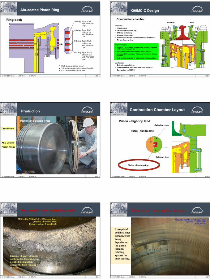
Alu-coated Piston Ring
Ring pack 1st ring: Type: CPR with Alu-Coat High
2nd ring: Type: RM5, oblique cut with Alu-Coat Low
3rd ring: Type: RM5, oblique cut with Alu-Coat Low
4th ring: Type: RM5, oblique cut with Alu-Coat Low
High topland piston crown 1st piston ring with increased height Copper band on piston skirt
2005.05.01 4140/PWN < 224 >
MAN B&W Diesel
© MAN B&W Diesel
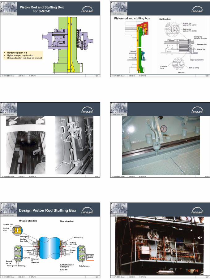
K90MC-C Design
Combustion chamberPrevious New
Features:• High topland• Oros shape of piston top• CPR top piston ring• Alu-coat piston rings• Bore cooled, forged piston of heat resistant steel• Piston cleaning ring
Improvements:• Approx. 100 °C lower temperature on top compared
with former type piston• Elimination of inconel coating on piston top• Increased chrome layer thickness in bottom of ring
grooves• Anti erosion bushing in oil outlet in piston rod foot
Verification:• Extensive calculations• Comprehensive tests on K90MC and K90MC-C • Service test on K90MC
2005.05.01 4140/PWN
< 225 >
MAN B&W Diesel
© MAN B&W Diesel
Production
Piston and piston rings
Oros Piston
ALU Coated
Piston Rings
2005.05.01 4140/PWN < 226 >
MAN B&W Diesel
© MAN B&W Diesel
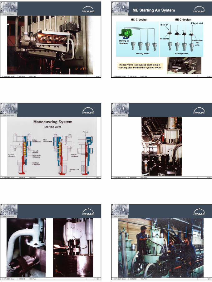
Combustion Chamber Layout
Piston – high top land
Piston – high top land
Cylinder cover
Cylinder liner
Piston cleaning ring
2005.05.01 4140/PWN
< 228 >
MAN B&W Diesel
© MAN B&W Diesel
• Example of heavy deposits on the piston topland, being polished from rubbing against the liner running surface
“Bore polish” from topland deposits.
2005.05.01 4140/PWN < 229 >
MAN B&W Diesel
© MAN B&W Diesel
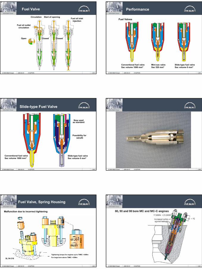
Example of,polished liner surface, from heavy deposits on the piston topland, rubbing against the liner surface.
“Bore polish” from topland deposits.
2005.05.01 4140/PWN
33
< 230 >
MAN B&W Diesel
© MAN B&W Diesel
Piston Rod and Stuffing Box for S-MC-C
• Hardened piston rod• Higher scraper ring tension• Reduced piston rod drain oil amount
2005.05.01 4140/PWN < 231 >
MAN B&W Diesel
© MAN B&W Diesel 2005.05.01 4140/PWN
< 232 >
MAN B&W Diesel
© MAN B&W Diesel 2005.05.01 4140/PWN < 233 >
MAN B&W Diesel
© MAN B&W Diesel 2005.05.01 4140/PWN
< 234 >
MAN B&W Diesel
© MAN B&W Diesel
Design Piston Rod Stuffing Box
Scraper ring
Sealingring
Sealing ring
Scraperring
Scraperring
Sealing ring
Return oilto crankcase
Relief groove Base ring
Back upspring
No reliefgroove
Relief groove
Stuffingbox drain
Lamella
Original standard New standard
Stuffing box drain
SL Modification of stuffing box
SL 02-408
2005.05.01 4140/PWN < 237 >
MAN B&W Diesel
© MAN B&W Diesel 2005.05.01 4140/PWN
34
< 239 >
MAN B&W Diesel
© MAN B&W Diesel 2005.05.01 4140/PWN < 240 >
MAN B&W Diesel
© MAN B&W Diesel
ME Starting ME Starting AirAir SystemSystem
MCMC--C designC design MEME--C designC design
Starting valvesStarting valvesStarting valvesStarting valves
Starting airStarting airNCNC--valvesvalves
Pilot air inletPilot air inletBlowBlow--offoff
Connection Connection forfor
ECSECSdistributordistributor
The NC valve is mounted on the main The NC valve is mounted on the main starting pipe behind the cylinder coverstarting pipe behind the cylinder cover
2005.05.01 4140/PWN
< 241 >
MAN B&W Diesel
© MAN B&W Diesel 2005.05.01 4140/PWN < 242 >
MAN B&W Diesel
© MAN B&W Diesel 2005.05.01 4140/PWN
< 243 >
MAN B&W Diesel
© MAN B&W Diesel 2005.05.01 4140/PWN < 244 >
MAN B&W Diesel
© MAN B&W Diesel 2005.05.01 4140/PWN

35
< 245 >
MAN B&W Diesel
© MAN B&W Diesel 2005.05.01 4140/PWN < 246 >
MAN B&W Diesel
© MAN B&W Diesel 2005.05.01 4140/PWN
< 247 >
MAN B&W Diesel
© MAN B&W Diesel 2005.05.01 4140/PWN < 248 >
MAN B&W Diesel
© MAN B&W Diesel
Drain
High pressure fuel
Atmospheric air
Highpressurefuel to fuel valve
Fuel pump barrel
Lube hole
Fuel pump plunger
Fuel inlet
Fuel pump housing
Low pressure fuel
Suction valve
Fuel pump top cover
Puncture valvehigh pressure
Piston for puncture valve
Drain
2005.05.01 4140/PWN
< 249 >
MAN B&W Diesel
© MAN B&W Diesel 2005.05.01 4140/PWN < 251 >
MAN B&W Diesel
© MAN B&W Diesel 2005.05.01 4140/PWN
36
< 253 >
MAN B&W Diesel
© MAN B&W Diesel
Circulation Start of openingFuel oil inlet
injection
Fuel oil outletcirculation
Open Closed Closed
Fuel Valve
2005.05.01 4140/PWN < 255 >
MAN B&W Diesel
© MAN B&W Diesel
Performance
Fuel Valves
Conventional fuel valveSac volume 1690 mm3
Mini-sac valveSac 520 mm3
Slide-type fuel valveSac volume 0 mm3
2005.05.01 4140/PWN
< 256 >
MAN B&W Diesel
© MAN B&W Diesel
Slide-type Fuel Valve
Conventional fuel valveSac volume 1690 mm3
Now usedas standard
Slide-type fuel valveSac volume 0 mm3
Possibility for retrofit
2005.05.01 4140/PWN < 258 >
MAN B&W Diesel
© MAN B&W Diesel 2005.05.01 4140/PWN
< 260 >
MAN B&W Diesel
© MAN B&W Diesel
SL 94-316
Fuel Valve, Spring Housing
Malfunction due to incorrect tightening
Tightening torque for engines up to 70MC = 60Nm
For large bore above 70MC = 65Nm
2005.05.01 4140/PWN < 261 >
MAN B&W Diesel
© MAN B&W Diesel 2005.05.01 4140/PWN
37
< 262 >
MAN B&W Diesel
© MAN B&W Diesel
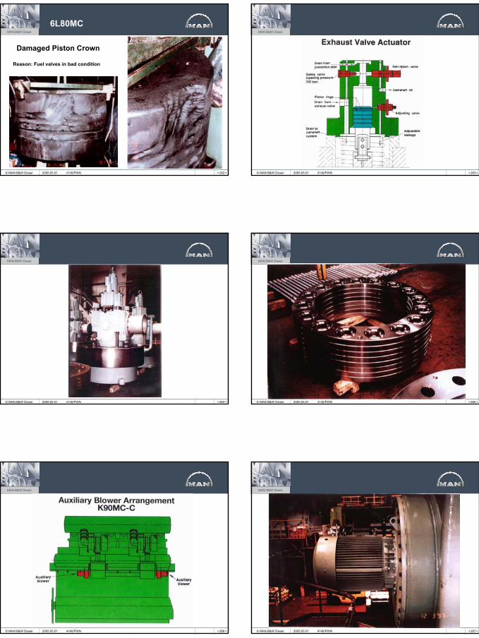
6L80MC
Damaged Piston Crown
Reason: Fuel valves in bad condition
2005.05.01 4140/PWN < 263 >
MAN B&W Diesel
© MAN B&W Diesel 2005.05.01 4140/PWN
< 264 >
MAN B&W Diesel
© MAN B&W Diesel 2005.05.01 4140/PWN < 265 >
MAN B&W Diesel
© MAN B&W Diesel 2005.05.01 4140/PWN
< 266 >
MAN B&W Diesel
© MAN B&W Diesel 2005.05.01 4140/PWN < 267 >
MAN B&W Diesel
© MAN B&W Diesel 2005.05.01 4140/PWN
38
< 268 >
MAN B&W Diesel
© MAN B&W Diesel 2005.05.01 4140/PWN < 269 >
MAN B&W Diesel
© MAN B&W Diesel 2005.05.01 4140/PWN
< 270 >
MAN B&W Diesel
© MAN B&W Diesel 2005.05.01 4140/PWN < 271 >
MAN B&W Diesel
© MAN B&W Diesel 2005.05.01 4140/PWN
< 272 >
MAN B&W Diesel
© MAN B&W Diesel 2005.05.01 4140/PWN < 273 >
MAN B&W Diesel
© MAN B&W Diesel
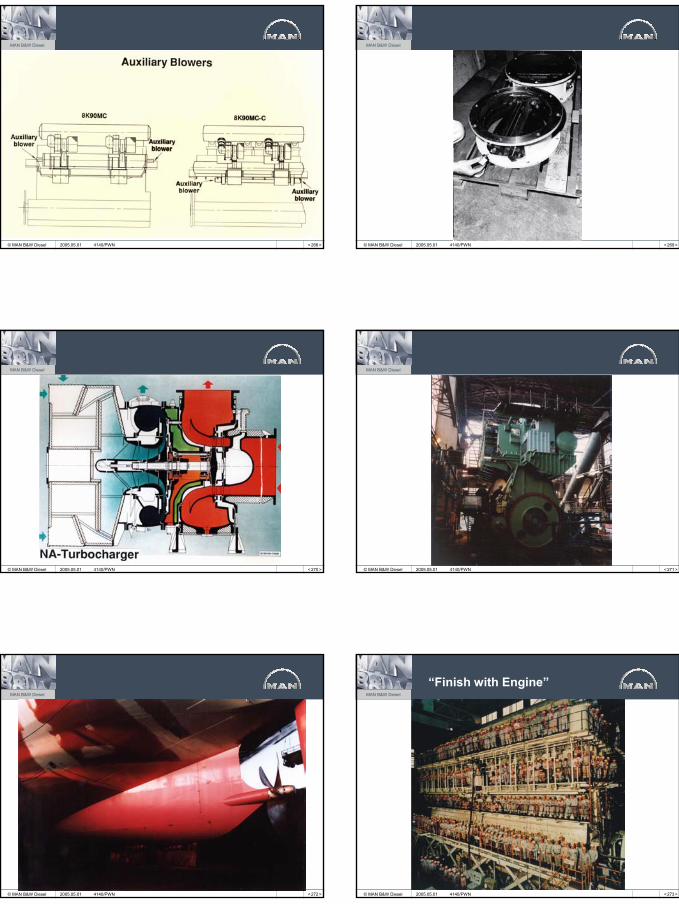
“Finish with Engine”
2005.05.01 4140/PWN

39
< 274 >
MAN B&W Diesel
© MAN B&W Diesel 2005.05.01 4140/PWN
Related Documents