11 Making Virtual Walking Real: Perceptual Evaluation of a New Treadmill Control Algorithm JAN L. SOUMAN Max Planck Institute for Biological Cybernetics, T¨ ubingen, Germany PAOLO ROBUFFO GIORDANO DIS, Universit` a di Roma “La Sapienza”, Roma, Italy and Max Planck Institute for Biological Cybernetics, T¨ ubingen, Germany ILJA FRISSEN Max Planck Institute for Biological Cybernetics, T ¨ ubingen, Germany and McGill University, Montreal, Canada ALESSANDRO DE LUCA DIS, Universit` a di Roma “La Sapienza”, Roma, Italy and MARC O. ERNST Max Planck Institute for Biological Cybernetics, T¨ ubingen, Germany For us humans, walking is our most natural way of moving through the world. One of the major challenges in present research on navigation in virtual reality is to enable users to physically walk through virtual environments. Although treadmills, in principle, allow users to walk for extended periods of time through large virtual environments, existing setups largely fail to produce a truly immersive sense of navigation. Partially, this is because of inadequate control of treadmill speed as a function of walking behavior. Here, we present a new control algorithm that allows users to walk naturally on a treadmill, including starting to walk from standstill, stopping, and varying walking speed. The treadmill speed control consists of a feedback loop based on the measured user position relative to a given reference position, plus a feed-forward term based on online estimation of the user’s walking velocity. The purpose of this design is to make the treadmill compensate fully for any persistent walker motion, while keeping the accelerations exerted on the user as low as possible. We evaluated the performance of the algorithm by conducting a behavioral experiment in which we varied its most important parameters. Participants walked at normal walking speed and then, on an auditory cue, abruptly stopped. After being brought back to the center of the treadmill by the control algorithm, they rated how smoothly the treadmill had changed its velocity in response to the change in walking speed. Ratings, in general, were quite high, indicating good control performance. Moreover, ratings clearly depended on the control algorithm parameters that were varied. Ratings were especially affected by the way the treadmill reversed its direction of motion. In conclusion, controlling treadmill speed in such a way that changes in treadmill speed are unobtrusive and do not disturb VR immersiveness is feasible on a normal treadmill with a straightforward control algorithm. The research described in this article was funded by the European research project Cyberwalk (Contract FP6-511092; see http://www.cyberwalk-project.org). A short video showing the behavior of the control system can be found at http://www.cyberwalk- project.org/img/Media/LTMctrl.mpg. Authors’ addresses: J. L. Souman, Max Planck Institute for Biological Cybernetics Multisensory Perception & Action Group, Spemannstraße 41, D-72076 T ¨ ubingen (Germany); email: [email protected]. Permission to make digital or hard copies of part or all of this work for personal or classroom use is granted without fee provided that copies are not made or distributed for profit or commercial advantage and that copies show this notice on the first page or initial screen of a display along with the full citation. Copyrights for components of this work owned by others than ACM must be honored. Abstracting with credit is permitted. To copy otherwise, to republish, to post on servers, to redistribute to lists, or to use any component of this work in other works requires prior specific permission and/or a fee. Permissions may be requested from Publications Dept., ACM, Inc., 2 Penn Plaza, Suite 701, New York, NY 10121-0701 USA, fax +1 (212) 869-0481, or [email protected]. c 2010 ACM 1544-3558/2010/02-ART11 $10.00 DOI 10.1145//1670671.1670675 http://doi.acm.org/10.1145/1670671.1670675 ACM Transactions on Applied Perception, Vol. 7, No. 2, Article 11, Publication date: February 2010.

Welcome message from author
This document is posted to help you gain knowledge. Please leave a comment to let me know what you think about it! Share it to your friends and learn new things together.
Transcript

11
Making Virtual Walking Real: Perceptual Evaluationof a New Treadmill Control Algorithm
JAN L. SOUMANMax Planck Institute for Biological Cybernetics, Tubingen, GermanyPAOLO ROBUFFO GIORDANODIS, Universita di Roma “La Sapienza”, Roma, Italy andMax Planck Institute for Biological Cybernetics, Tubingen, GermanyILJA FRISSENMax Planck Institute for Biological Cybernetics, Tubingen, Germany and McGill University, Montreal, CanadaALESSANDRO DE LUCADIS, Universita di Roma “La Sapienza”, Roma, ItalyandMARC O. ERNSTMax Planck Institute for Biological Cybernetics, Tubingen, Germany
For us humans, walking is our most natural way of moving through the world. One of the major challenges in present research onnavigation in virtual reality is to enable users to physically walk through virtual environments. Although treadmills, in principle,allow users to walk for extended periods of time through large virtual environments, existing setups largely fail to produce atruly immersive sense of navigation. Partially, this is because of inadequate control of treadmill speed as a function of walkingbehavior. Here, we present a new control algorithm that allows users to walk naturally on a treadmill, including starting towalk from standstill, stopping, and varying walking speed. The treadmill speed control consists of a feedback loop based on themeasured user position relative to a given reference position, plus a feed-forward term based on online estimation of the user’swalking velocity. The purpose of this design is to make the treadmill compensate fully for any persistent walker motion, whilekeeping the accelerations exerted on the user as low as possible.
We evaluated the performance of the algorithm by conducting a behavioral experiment in which we varied its most importantparameters. Participants walked at normal walking speed and then, on an auditory cue, abruptly stopped. After being broughtback to the center of the treadmill by the control algorithm, they rated how smoothly the treadmill had changed its velocity inresponse to the change in walking speed. Ratings, in general, were quite high, indicating good control performance. Moreover,ratings clearly depended on the control algorithm parameters that were varied. Ratings were especially affected by the way thetreadmill reversed its direction of motion. In conclusion, controlling treadmill speed in such a way that changes in treadmillspeed are unobtrusive and do not disturb VR immersiveness is feasible on a normal treadmill with a straightforward controlalgorithm.
The research described in this article was funded by the European research project Cyberwalk (Contract FP6-511092; seehttp://www.cyberwalk-project.org). A short video showing the behavior of the control system can be found at http://www.cyberwalk-project.org/img/Media/LTMctrl.mpg.Authors’ addresses: J. L. Souman, Max Planck Institute for Biological Cybernetics Multisensory Perception & Action Group,Spemannstraße 41, D-72076 Tubingen (Germany); email: [email protected] to make digital or hard copies of part or all of this work for personal or classroom use is granted without fee providedthat copies are not made or distributed for profit or commercial advantage and that copies show this notice on the first pageor initial screen of a display along with the full citation. Copyrights for components of this work owned by others than ACMmust be honored. Abstracting with credit is permitted. To copy otherwise, to republish, to post on servers, to redistribute tolists, or to use any component of this work in other works requires prior specific permission and/or a fee. Permissions may berequested from Publications Dept., ACM, Inc., 2 Penn Plaza, Suite 701, New York, NY 10121-0701 USA, fax +1 (212) 869-0481,or [email protected]© 2010 ACM 1544-3558/2010/02-ART11 $10.00
DOI 10.1145//1670671.1670675 http://doi.acm.org/10.1145/1670671.1670675
ACM Transactions on Applied Perception, Vol. 7, No. 2, Article 11, Publication date: February 2010.
11:2 • J. L. Souman et al.
Categories and Subject Descriptors: H.1.2 [Information Systems]: User/Machine Systems—Human Factors; H.5.2 [Informa-tion Interfaces]: User Interfaces—Evaluation/methodology
General Terms: Experimentation, Human Factors, MeasurementAdditional Key Words and Phrases: Virtual reality, treadmill walking, motion control
ACM Reference Format:Souman, J. L., Giordano, P. R., Frissen, I., De Luca, A., and Ernst, M. O. 2010. Making virtual walking real: Perceptual evaluationof a new treadmill control algorithm. ACM Trans. Appl. Percept. 7, 2, Article 11 (February 2010), 14 pages.DOI = 10.1145/1670671.1670675 http://doi.acm.org/10.1145/1670671.1670675
1. INTRODUCTION
In recent years, virtual reality (VR) has become increasingly realistic and immersive. Both the visualand auditory rendering of virtual environments have been improved significantly, thanks to develop-ments in both hardware and software. In contrast, the possibilities for intuitive navigation throughvirtual environments (VE) are still relatively rudimentary. Most commonly, users can “move” throughhigh-fidelity virtual environments using a mouse or a joystick. Of course, the most natural way tonavigate through VR would be to walk. For small scale virtual environments, one can simply walkwithin a confined space. The VE can be presented by a cave-like projection system, or by means ofa head-mounted display combined with head-tracking. For larger VEs, however, this quickly becomesimpractical or even impossible.
In principle, a more general solution is offered by treadmills, as they keep the user in a relativelyrestricted area while at the same time allowing to walk through arbitrarily large VEs. At present,however, the treadmill solution is still far from satisfactory because of two problems. First, most of thecurrent treadmill set-ups only allow for walking in one direction, severely restricting the possibilitiesfor navigation through VEs. Although several attempts have been made to create an omnidirectionaltreadmill, allowing users to walk in any direction, most of these solutions at present still are in theprototype state and often are far from perfect [Darken et al. 1997; Iwata 1999; Fernandes et al. 2003;Huang 2003; Nagamori et al. 2005].
The second major problem in using treadmills for VE navigation is how to control the velocity of thetreadmill as a function of the walking behavior of the user. Obviously, the user should be kept on thetreadmill while either walking or standing still. Most available set-ups, therefore, allow the user to walkat only one fixed speed, given by the treadmill. A better solution would be to have the treadmill respondto changes in walking speed, but this creates its own set of problems. Acceleration of the treadmillcannot be too high, because this would disrupt the immersiveness of the VR or even bring the user outof balance. On the other hand, it cannot be too low either, because then the person would walk off thetreadmill when he or she changes walking speed.
This article focuses on the second problem. We developed a control algorithm to control the speedof a treadmill in such a way that VR immersiveness is not disrupted by changes in treadmill velocity[De Luca et al. 2006a; 2006b; 2007]. This algorithm was developed to work with an omnidirectionaltreadmill, allowing for changes in both walking speed and direction. In this article, we describe a one-dimensional variant of the algorithm and report the results of an experiment that we conducted toevaluate its effectiveness. The algorithm can be used to control a normal, linear treadmill, within thelimits of its size and speed. The treadmill will respond smoothly to changes in walking speed, allowingthe user to start walking from standstill, to vary walking speed in a natural way, and even to abruptlystop walking without obtrusive changes in treadmill speed.ACM Transactions on Applied Perception, Vol. 7, No. 2, Article 11, Publication date: February 2010.

Making Virtual Walking Real • 11:3
We had two main objectives in mind when we developed and evaluated the control algorithm. First,we wanted to allow for acceleration and deceleration of the user with respect to the treadmill belt,retaining inertial cues to changes in walking speed. These cues have been shown to be important, bothfor maintaining postural stability during walking and for the perception of walking speed [Jahn et al.2000; Mittelstaedt & Mittelstaedt 2001; Cathers et al. 2005; Fitzpatrick et al. 2006]. For this reason,recently described solutions for keeping the user in a more or less constant position with varying walkingspeeds are unsatisfactory for the purpose of creating a truly immersive virtual-walking environment[Minetti et al. 2003; Lichtenstein et al. 2007]. One approach to solve this problem is to simulate theinertial forces during normal walking while walking in place. This has been done by means of aninertial-force feedback device (a tether), which either pushes or pulls at the back of a person walking onthe treadmill [Christensen et al. 2000; Hollerbach et al. 2000]. These studies report that applying theforce-feedback improved the degree to which walking on the treadmill was perceived as realistic andnatural. The necessary tether forces were mitigated by also allowing for some forward motion of theuser on the treadmill. However, one problem with this solution is how to transfer the forces from theforce feedback device to the torso of the user. Even with a very stiff harness, force application still differsfor accelerations versus decelerations [Checcacci et al. 2003]. In addition, using a mechanic solutionfor the inertial forces problem makes it more complicated to use for a truly omnidirectional treadmill.Therefore, rather than keeping the user in place and simulating the inertial forces, we decided to allowthe user to actually move with respect to the treadmill, keeping the normal inertial cues that occurwith changes in walking speed.
Our second objective was to make changes in treadmill speed as smooth as possible and to avoid anyjumps in commanded treadmill speed. Fast accelerations of the treadmill would be easily detectableby the user and might lead to instability or loss of balance while walking or standing. Furthermore, ifthe treadmill is used to navigate through VEs, high accelerations will disrupt the immersiveness of theVR. Our evaluation experiment was specifically targeted at fine-tuning the control algorithm describedin the following text in order to minimize the obtrusiveness of changes in treadmill speed. To this end,various parameters of the algorithm were systematically varied.
2. CONTROL ALGORITHM
We decided to allow for normal acceleration and deceleration through space rather than keeping theuser in place on the treadmill. Our algorithm allows the user to start walking on a stationary treadmilland the treadmill will only gradually respond to the movement of the user. Similarly, when the userstops walking, the treadmill only gradually comes to a halt and brings the user back to the centerof the treadmill. This strategy works best with a relatively large treadmill, but the algorithm can beimplemented with treadmills of any size.
The purpose of the control algorithm is to keep the walking person close to a predefined referenceposition (the center of the treadmill), while keeping changes in treadmill speed as unobtrusive aspossible. Formally, this can be described as an output regulation of the position of the user x alongthe main axis of the treadmill to a reference position xref in the presence of unknown disturbances(the intended voluntary user walking speed Vw), with vC as the available treadmill speed command. Indeveloping our control algorithm, we started with a simple first-order control law, that is, by assumingtreadmill velocity as the available input. However, in pilot studies that evaluated this control algorithm,we realized that we had to extend this design to a second-order level (with treadmill acceleration as newinput) to take into account suitable acceleration bounds in the treadmill speed command. In addition,we decided to use an adaptive reference position, dependent on the walking speed of the user. Thesethree levels of control are described in the following text.
ACM Transactions on Applied Perception, Vol. 7, No. 2, Article 11, Publication date: February 2010.
11:4 • J. L. Souman et al.
2.1 First-Order Control Law
A first-order kinematic model of the treadmill/user system can be expressed as{x = −vC + Vw
y = x , (1)
where y stands for the system measurable output, that is, the absolute user position. The sign of vC inEquation (1) is due to our definition of the direction of walking and treadmill motion: Forward walking(positive change in user position x) corresponds to backwards motion of the treadmill belt (vC). Whenthe user stands still (Vw = 0), exponential stabilization of Equation (1) at a given xref can be achievedby means of the simple proportional feedback
vC = kpos(x − xref), (2)
where gain kpos > 0 tunes the convergence rate. In the presence of persistent walker motion, however,Equation (2) is not able to fully recover the reference position xref. In particular, if the user walksindefinitely with constant velocity Vw, at steady state, a position error Vw
kposfrom xref will be present. In
order to compensate for the walker’s locomotion and make the system partially insensitive to changesin walking speed, feedback (Equation (2)) can be complemented with a feed-forward term based ononline estimation of walking velocity Vw. Such an estimated value Vw is obtained as output of thescalar dynamic observer system {
ξ = −vC + kobv(x − ξ )Vw = kobv(x − ξ ) , kobv > 0. (3)
Here, variable ξ represents the internal state of the observer that evolves according to the first rowin Equation (3). The second row can be seen as the output of the observer, where the estimation of thevelocity is computed in terms of the measurement x and the internal state ξ . This observer output isthen added to Equation (2) to get the feedback/feed-forward law
vC = kpos(x − xref) + Vw. (4)
Note that, implementation of Equation (3) requires the knowledge of the treadmill velocity vC besidesthe user position x. Moreover, from Equations (3) and (1), it follows ˙V w = kobv(Vw − Vw), which canbe shown to result in Vw as a low-pass filtered version of Vw with the cut-off frequency tuned by kobv.By analyzing the overall closed-loop system in the Laplace domain, it is possible to prove that (atsteady-state) feedback (Equation 4) fully recovers the reference position xref in presence of any constantdisturbance Vw. In practice, the observer acts as an independent dynamical system with its own internalstate, designed so that it can asymptotically track the behavior of the unmeasurable intentional velocityVw(t) of the walker (see Appendix A for further details).
2.2 Second-Order Control Law
Feedback/feed-forward system (Equation (1)) together with observer (Equation (3)) is able to meet thecontrol goals stated at the beginning of this section: output regulation to xref despite the presence of apersistent disturbance Vw. However, this first-order design of Equations (1) and (4) does not allow anyexplicit control over the imposed accelerations during transients in walking speed. As stated earlierin the text, it is important to avoid big acceleration steps in treadmill speed (discontinuities in vC)and to limit the maximum acceleration imposed on the walker in order to allow for truly immersivelocomotion through VEs. A convenient way to explicitly address these issues is to perform a dynamicextension of Equation (1) by considering vC as a state of the system, and its derivative vC = aC as theACM Transactions on Applied Perception, Vol. 7, No. 2, Article 11, Publication date: February 2010.
Making Virtual Walking Real • 11:5
new (acceleration) input signal. Thus, we obtain the extended second-order walker/treadmill system⎧⎨⎩
x = −vC + VwvC = aC
y = x. (5)
Now, aC is the new control input and continuity of state vC is automatically guaranteed, that is, novelocity steps can be commanded. Moreover, bounds on the imposed acceleration can be directly im-plemented. A number of methodologies for dynamic extension of lower-order control laws have beenproposed in the control literature, such as backstepping [Krstic et al. 1995] and the theory of cascadedsystems [Panteley and Lorya 1998]. In the following, we will adopt the latter for our second-order controllaw design.
Let vdC(t) represent the nominal first-order control law (Equation (4)) developed for the original system
(Equation (1)). Intuitively, the new command input aC should impose a perfect tracking of vdC(t) on the
new state vC in order to reproduce the same behavior of the first-order scheme. This can be achievedby designing aC as
aC = dvdC(t)
dt+ ka(vd
C(t) − vC) = kpos(−vC + Vw) + ˙V w + ka(kpos(x − xref) + Vw − vC), (6)
where ka > 0 is a suitable gain. According to the theory of cascaded systems, feedback (Equation (6))is able to stabilize the system (Equation (5)) by achieving an asymptotic tracking of vd
C(t), tuned by thevalue of ka. Note, however, that implementation of Equation (6), requires some quantities that cannotbe directly measured, that is, walker velocity Vw, and ˙V w = kobv(Vw − Vw) which again depends onVw. For this reason, we decided to implement an approximated version of Equation (6), where Vw isreplaced by its estimateVw, and ˙V w is neglected. Therefore, the implemented acceleration-level controllaw is
aC = kpos(−vC + Vw) + ka(kpos(x − xref) + Vw − vC). (7)
By studying the characteristics of this control law in the Laplace domain, one can verify that closed-loop stability is preserved despite the approximations done in Equation (7) with respect to the nominalcontrol law (Equation 6) (see Appendix A). Note that our setup does not allow a direct accelerationcommand but only a velocity command. The corresponding velocity command vC sent to the treadmillcan be recovered from Equation (7) by means of a software integration vC = ∫
acdt.
2.3 Tuning of the Reference Position
The largest changes in commanded treadmill speed will occur when the user starts walking fromstanding still or abruptly stops from walking at normal speed. At steady state, the treadmill velocityvC exactly matches (with opposite sign) the user velocity Vw. Hence, when the user starts walking, thecontrol must accelerate from vc = 0 to −Vw. Vice versa, when the user stops, the control must deceleratefrom vC = −Vw to 0. Because the user must be kept within the treadmill boundaries, this poses a lowerbound on the necessary acceleration/deceleration. At the same time, the acceleration must be kept lowenough not to interfere with the immersiveness of the VR. These two criteria may be incompatible witheach other. A possible way to relax the lower acceleration bound is to “virtually” increase the size of thetreadmill by changing the reference position xref according to the user velocity Vw: The faster the usermoves, the more xref is shifted toward the treadmill border in the walking direction of the user. Suchbehavior can be implemented by defining
xref = krefVw + xref,0, (8)
ACM Transactions on Applied Perception, Vol. 7, No. 2, Article 11, Publication date: February 2010.
11:6 • J. L. Souman et al.
1/s 1/s+
-
Velocityobserver
Control law
Saturation
Vw~
Vw
xref
ac
vc x
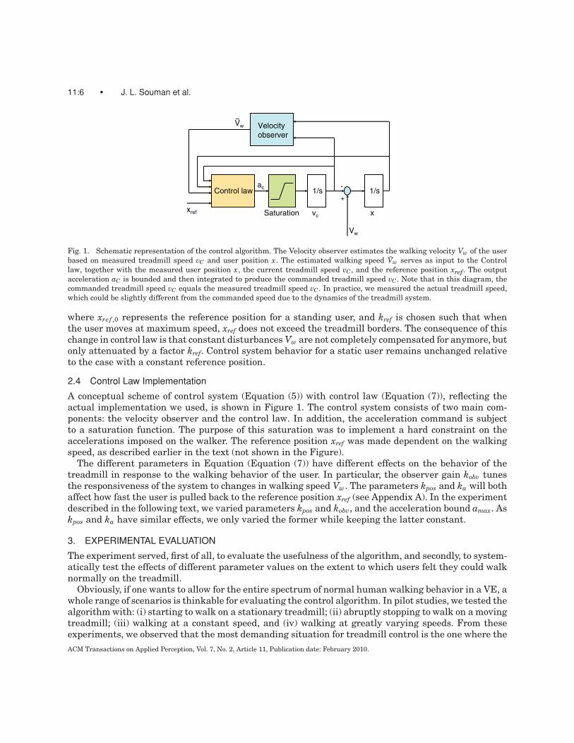
Fig. 1. Schematic representation of the control algorithm. The Velocity observer estimates the walking velocity Vw of the userbased on measured treadmill speed vC and user position x. The estimated walking speed Vw serves as input to the Controllaw, together with the measured user position x, the current treadmill speed vC , and the reference position xref. The outputacceleration aC is bounded and then integrated to produce the commanded treadmill speed vC . Note that in this diagram, thecommanded treadmill speed vC equals the measured treadmill speed vC . In practice, we measured the actual treadmill speed,which could be slightly different from the commanded speed due to the dynamics of the treadmill system.
where xref ,0 represents the reference position for a standing user, and kref is chosen such that whenthe user moves at maximum speed, xref does not exceed the treadmill borders. The consequence of thischange in control law is that constant disturbances Vw are not completely compensated for anymore, butonly attenuated by a factor kref. Control system behavior for a static user remains unchanged relativeto the case with a constant reference position.
2.4 Control Law Implementation
A conceptual scheme of control system (Equation (5)) with control law (Equation (7)), reflecting theactual implementation we used, is shown in Figure 1. The control system consists of two main com-ponents: the velocity observer and the control law. In addition, the acceleration command is subjectto a saturation function. The purpose of this saturation was to implement a hard constraint on theaccelerations imposed on the walker. The reference position xref was made dependent on the walkingspeed, as described earlier in the text (not shown in the Figure).
The different parameters in Equation (Equation (7)) have different effects on the behavior of thetreadmill in response to the walking behavior of the user. In particular, the observer gain kobv tunesthe responsiveness of the system to changes in walking speed Vw. The parameters kpos and ka will bothaffect how fast the user is pulled back to the reference position xref (see Appendix A). In the experimentdescribed in the following text, we varied parameters kpos and kobv, and the acceleration bound amax. Askpos and ka have similar effects, we only varied the former while keeping the latter constant.
3. EXPERIMENTAL EVALUATION
The experiment served, first of all, to evaluate the usefulness of the algorithm, and secondly, to system-atically test the effects of different parameter values on the extent to which users felt they could walknormally on the treadmill.
Obviously, if one wants to allow for the entire spectrum of normal human walking behavior in a VE, awhole range of scenarios is thinkable for evaluating the control algorithm. In pilot studies, we tested thealgorithm with: (i) starting to walk on a stationary treadmill; (ii) abruptly stopping to walk on a movingtreadmill; (iii) walking at a constant speed, and (iv) walking at greatly varying speeds. From theseexperiments, we observed that the most demanding situation for treadmill control is the one where theACM Transactions on Applied Perception, Vol. 7, No. 2, Article 11, Publication date: February 2010.
Making Virtual Walking Real • 11:7
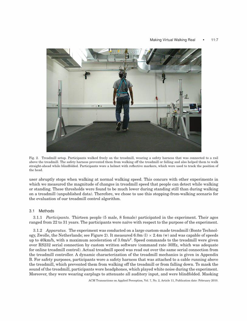
Fig. 2. Treadmill setup. Participants walked freely on the treadmill, wearing a safety harness that was connected to a railabove the treadmill. The safety harness prevented them from walking off the treadmill or falling and also helped them to walkstraight-ahead while blindfolded. Participants wore a helmet with reflective markers, which were used to track the position ofthe head.
user abruptly stops when walking at normal walking speed. This concurs with other experiments inwhich we measured the magnitude of changes in treadmill speed that people can detect while walkingor standing. These thresholds were found to be much lower during standing still than during walkingon a treadmill (unpublished data). Therefore, we chose to use this stopping-from-walking scenario forthe evaluation of our treadmill control algorithm.
3.1 Methods
3.1.1 Participants. Thirteen people (5 male, 8 female) participated in the experiment. Their agesranged from 22 to 31 years. The participants were naıve with respect to the purpose of the experiment.
3.1.2 Apparatus. The experiment was conducted on a large custom-made treadmill (Bonte Technol-ogy, Zwolle, the Netherlands; see Figure 2). It measured 6.0m (l) × 2.4m (w) and was capable of speedsup to 40km/h, with a maximum acceleration of 3.0m/s2. Speed commands to the treadmill were givenover RS232 serial connection by custom written software (command rate 30Hz, which was adequatefor online treadmill control). Actual treadmill speed was read out over the same serial connection fromthe treadmill controller. A dynamic characterization of the treadmill mechanics is given in AppendixB. For safety purposes, participants wore a safety harness that was attached to a cable running abovethe treadmill, which prevented them from walking off the treadmill or from falling down. To mask thesound of the treadmill, participants wore headphones, which played white noise during the experiment.Moreover, they were wearing earplugs to attenuate all auditory input, and were blindfolded. Masking
ACM Transactions on Applied Perception, Vol. 7, No. 2, Article 11, Publication date: February 2010.

11:8 • J. L. Souman et al.
noise and earplugs together ensured that participants did not received auditory cues to changes intreadmill speed.
The position of the participant on the treadmill was measured with a Vicon optical infrared trackingsystem (Vicon, Oxford, UK). It tracked reflective markers that were mounted on a helmet worn bythe participant (sampling rate 120Hz). From the marker positions, the position of the head of theparticipant was computed. Together with the actual treadmill speed provided by the treadmill, thisformed the input into the control algorithm.
3.1.3 Procedure. As indicated previously in the text, we varied three parameters of the controlalgorithm: the gain kobv with which the walking speed was estimated (0.3, 0.6, or 0.9), the positiongain kpos (0.5, 1.0, or 1.5), and the maximum acceleration amax commanded to the treadmill (1.0 or2.0m/s2). The appropriate ranges were established in pilot studies. All three parameters were combinedfactorially, resulting in 18 different conditions. All conditions were replicated five times, in randomorder. The first replication was considered training and these data were not used in the analysis.Before the experiment, the participants were allowed to walk on the treadmill with vision, experiencingthe response of the treadmill to their walking behavior. Experimental trials were performed whileblindfolded to ensure that participants would not use visual cues to changes in treadmill speed to basetheir judgments on.
Each trial started with the participant standing still on the reference position, while the treadmill wasstationary. After hearing a beep via the headphones, the participant started to walk forward normallyat his/her preferred speed. The safety harness provided a reference to walk straight. During this period,the treadmill responded to the walking behavior with a default set of parameter values that was usedin all trials (kobv = 3.0; kpos = 0.5; amax = 5.0). After 6s, a second beep indicated the participantto stop walking and stand still on the moving treadmill. From this point on, treadmill behavior wasgoverned by the parameter values of the condition tested. After the control algorithm had brought theparticipant back to the reference position and the treadmill was stationary again, a third beep promptedthe participant to give an oral rating of treadmill behavior. The rating had to reflect the degree to whichthe change in treadmill speed was noticeable from the point where he or she stopped walking up tothe last beep. The participant was instructed to give a rating from 1 to 10, where 1 represented thecase where he or she could not maintain balance and fell (which never happened) and 10 indicatedthat no change in treadmill motion was felt at all. The ratings were entered into the computer by theexperimenter.
4. RESULTS
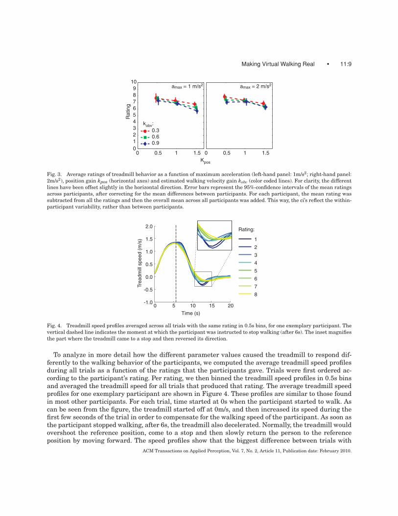
The ratings given by the participants were averaged across replications of the same condition by takingthe median value per participant. A univariate repeated measures ANOVA (SPSS 15.0) was performedto test for significance of the effects of the three parameters (kobv, kpos, and amax). The different parametervalues systematically caused the participants to judge the treadmill behavior differently. Figure 3 showsthe average ratings as a function of the three parameters that were varied. The error bars in this figurerepresent the 95%-confidence intervals of the mean responses across participants, after correcting forinterparticipant differences. Both the gain of the estimated walking velocity kobv and the position gainkpos had significant effects on the ratings that the participants gave (F(1.38, 16.56) = 9.93, p = 0.001,after Greenhouse-Geisser correction for asphericity, and F(2,24) = 18.99, p < 0.001, respectively). Ingeneral, the ratings were higher for lower values of these parameters. The acceleration limit amax didnot have a significant effect (compare the left-hand graph in Figure 3 with the right-hand graph; F(1,12)= 1.71, p = 0.215). This probably was because accelerations rarely were larger than 2.0m/s2. None ofthe interactions between the three parameters were significant.ACM Transactions on Applied Perception, Vol. 7, No. 2, Article 11, Publication date: February 2010.
Making Virtual Walking Real • 11:9
0 0.5 1 1.50123456789
10
Kpos
Rat
ing
0 0.5 1 1.5
amax = 1 m/s2 amax = 2 m/s2
0.30.60.9
kobv:
Fig. 3. Average ratings of treadmill behavior as a function of maximum acceleration (left-hand panel: 1m/s2; right-hand panel:2m/s2), position gain kpos (horizontal axes) and estimated walking velocity gain kobv (color coded lines). For clarity, the differentlines have been offset slightly in the horizontal direction. Error bars represent the 95%-confidence intervals of the mean ratingsacross participants, after correcting for the mean differences between participants. For each participant, the mean rating wassubtracted from all the ratings and then the overall mean across all participants was added. This way, the ci’s reflect the within-participant variability, rather than between participants.
0 10 20-1.0
-0.5
0.0
0.5
1.0
1.5
2.0
Time (s)
Trea
dmill
spe
ed (
m/s
)
1
2
3
4
5
6
7
8
Rating:
5 15
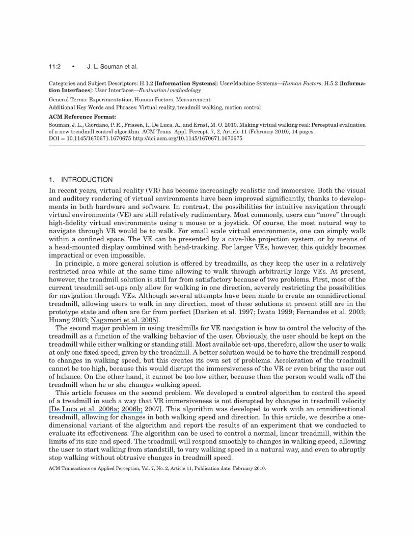
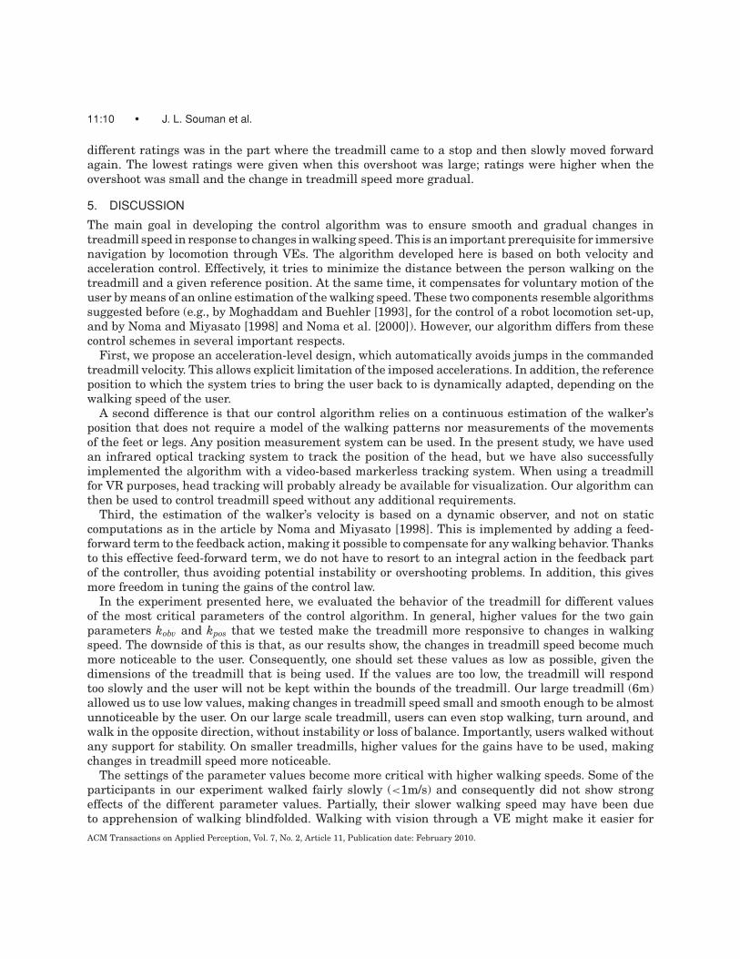
Fig. 4. Treadmill speed profiles averaged across all trials with the same rating in 0.5s bins, for one exemplary participant. Thevertical dashed line indicates the moment at which the participant was instructed to stop walking (after 6s). The inset magnifiesthe part where the treadmill came to a stop and then reversed its direction.
To analyze in more detail how the different parameter values caused the treadmill to respond dif-ferently to the walking behavior of the participants, we computed the average treadmill speed profilesduring all trials as a function of the ratings that the participants gave. Trials were first ordered ac-cording to the participant’s rating. Per rating, we then binned the treadmill speed profiles in 0.5s binsand averaged the treadmill speed for all trials that produced that rating. The average treadmill speedprofiles for one exemplary participant are shown in Figure 4. These profiles are similar to those foundin most other participants. For each trial, time started at 0s when the participant started to walk. Ascan be seen from the figure, the treadmill started off at 0m/s, and then increased its speed during thefirst few seconds of the trial in order to compensate for the walking speed of the participant. As soon asthe participant stopped walking, after 6s, the treadmill also decelerated. Normally, the treadmill wouldovershoot the reference position, come to a stop and then slowly return the person to the referenceposition by moving forward. The speed profiles show that the biggest difference between trials with
ACM Transactions on Applied Perception, Vol. 7, No. 2, Article 11, Publication date: February 2010.
11:10 • J. L. Souman et al.
different ratings was in the part where the treadmill came to a stop and then slowly moved forwardagain. The lowest ratings were given when this overshoot was large; ratings were higher when theovershoot was small and the change in treadmill speed more gradual.
5. DISCUSSION
The main goal in developing the control algorithm was to ensure smooth and gradual changes intreadmill speed in response to changes in walking speed. This is an important prerequisite for immersivenavigation by locomotion through VEs. The algorithm developed here is based on both velocity andacceleration control. Effectively, it tries to minimize the distance between the person walking on thetreadmill and a given reference position. At the same time, it compensates for voluntary motion of theuser by means of an online estimation of the walking speed. These two components resemble algorithmssuggested before (e.g., by Moghaddam and Buehler [1993], for the control of a robot locomotion set-up,and by Noma and Miyasato [1998] and Noma et al. [2000]). However, our algorithm differs from thesecontrol schemes in several important respects.
First, we propose an acceleration-level design, which automatically avoids jumps in the commandedtreadmill velocity. This allows explicit limitation of the imposed accelerations. In addition, the referenceposition to which the system tries to bring the user back to is dynamically adapted, depending on thewalking speed of the user.
A second difference is that our control algorithm relies on a continuous estimation of the walker’sposition that does not require a model of the walking patterns nor measurements of the movementsof the feet or legs. Any position measurement system can be used. In the present study, we have usedan infrared optical tracking system to track the position of the head, but we have also successfullyimplemented the algorithm with a video-based markerless tracking system. When using a treadmillfor VR purposes, head tracking will probably already be available for visualization. Our algorithm canthen be used to control treadmill speed without any additional requirements.
Third, the estimation of the walker’s velocity is based on a dynamic observer, and not on staticcomputations as in the article by Noma and Miyasato [1998]. This is implemented by adding a feed-forward term to the feedback action, making it possible to compensate for any walking behavior. Thanksto this effective feed-forward term, we do not have to resort to an integral action in the feedback partof the controller, thus avoiding potential instability or overshooting problems. In addition, this givesmore freedom in tuning the gains of the control law.
In the experiment presented here, we evaluated the behavior of the treadmill for different valuesof the most critical parameters of the control algorithm. In general, higher values for the two gainparameters kobv and kpos that we tested make the treadmill more responsive to changes in walkingspeed. The downside of this is that, as our results show, the changes in treadmill speed become muchmore noticeable to the user. Consequently, one should set these values as low as possible, given thedimensions of the treadmill that is being used. If the values are too low, the treadmill will respondtoo slowly and the user will not be kept within the bounds of the treadmill. Our large treadmill (6m)allowed us to use low values, making changes in treadmill speed small and smooth enough to be almostunnoticeable by the user. On our large scale treadmill, users can even stop walking, turn around, andwalk in the opposite direction, without instability or loss of balance. Importantly, users walked withoutany support for stability. On smaller treadmills, higher values for the gains have to be used, makingchanges in treadmill speed more noticeable.
The settings of the parameter values become more critical with higher walking speeds. Some of theparticipants in our experiment walked fairly slowly (<1m/s) and consequently did not show strongeffects of the different parameter values. Partially, their slower walking speed may have been dueto apprehension of walking blindfolded. Walking with vision through a VE might make it easier forACM Transactions on Applied Perception, Vol. 7, No. 2, Article 11, Publication date: February 2010.
Making Virtual Walking Real • 11:11
them to walk at a normal walking speed. On the other hand, adding a VE might also create a conflictbetween the perceived visual self-motion through the VE and the felt motion through the real world onthe treadmill. For instance, when the user stops walking, the visual environment will be stationary. Atthe same time, the user is moved through space by the treadmill in order to bring him/her back to thereference position. Whether these conflicts are large enough to be noticeable and what their effects willbe has to be further investigated. Previous studies have shown that humans calibrate their perceivedwalking speed to the visual optic flow experienced during walking. This suggests that, at least withtime, these conflicts do not necessarily disrupt VR immersiveness [Durgin et al. 2005; Mohler et al.,2007; Rieser et al., 1995]. Preliminary studies carried out on our treadmill set-up suggest that addinga visual VE indeed does improve stability during walking.
As indicated in the Introduction, controlling treadmill speed as a function of walking behavior isonly half the challenge of creating a truly immersive locomotion interface for VR. The other goal is tocreate an omnidirectional treadmill. We are currently developing such a treadmill. A two-dimensionalversion of the algorithm described here will be used for the control of this omnidirectional treadmill[De Luca et al. 2006a; 2006b; 2007]. Obviously, the demands on the control algorithm will be higher inthe omnidirectional case, as now not only speed but also walking direction can change. An indicationthat users are more sensitive to changes in treadmill direction than speed can be found in the resultsdescribed previously in the text. In our experiment, the most important part of the motion profileof the treadmill proved to be where it reversed its direction (Figure 4). More studies are needed toinvestigate whether this represents the most extreme case or that users are even more sensitive tointermediate direction changes. The results from the present study are encouraging evidence, however,that controlling treadmill velocity without disrupting the immersiveness of VR is indeed a feasibletask.
ACKNOWLEDGMENTS
The authors would like to thank Manish Sreenivasa and Michael Weyel for technical assistance, andRoy Ruddle for useful comments.
Appendix A: Stability of the Control System
A.1. Stability of First-Order Control System
Closed-loop behavior of system Equation (1) together with feedback Equation (4) can be convenientlystudied in the Laplace domain. As a preliminary step, it is useful to explicitly characterize the transferfunction linking Vw(s) to its estimate Vw(s). From Equations (1) and (3), it follows that ˙V w = kobv(Vw−Vw)from which we obtain
Vw(s) = kobv
s + kobvVw(s). (A1)
Hence, the estimate Vw results in a low-pass filtered version of Vw with cut-off frequency tuned bykobv. By plugging Equation (4) into Equation (1), and using the expression (A1), the closed-loop behaviorof the user position x is described by the Laplace relation
X (s) = kpos
s + kposX ref(s) + s
s + kobvVw(s) = F1(s)X ref(s) + F2(s)Vw(s). (A2)
Therefore, one can verify that, at steady state, any constant disturbance Vw(s) = Vws is fully compen-
sated thanks to the zero in s = 0 of F2(s), that is, the term F2(s) · Vws = Vw
s+kobvexponentially vanishes
over time for any Vw. Moreover, any constant reference position xref is also correctly reproduced atACM Transactions on Applied Perception, Vol. 7, No. 2, Article 11, Publication date: February 2010.
11:12 • J. L. Souman et al.
steady state, since F1(s)∣∣s=0 = 1, that is, F1(s) has an unitary steady-state gain. This, together with
the rejection properties of F2(s), ensures that limt→∞ x(t) = xref for a person who stands still or walks at a
constant speed.
A.2. Stability of Second-Order Control System
Stability of the closed-loop behavior of (Equation (5)) together with feedback (Equation (7)) can be againanalyzed in the Laplace domain. By plugging Equation (7) in Equation (5), and using Equation (A1),we get the closed-loop transfer functions
X (s) = kposka
(s + kpos)(s + ka)X ref(s) + s(s + kobv + kpos + ka)
(s + kobv)(s + kpos)(s + ka)Vw(s) =
= F3(s)X ref(s) + F4(s)Vw(s), (A3)
which are stable (poles with negative real part) as long as kpos > 0, ka > 0 and kobv > 0. Hence, stabilityis guaranteed by imposing positive gains, in contrast to, for example, Noma and Miyasato [1998], wherethe control gains are restricted to a specific stability region. Our implementation allows better tuningof the overall control law.
Note that gains ka and kpos appear symmetrically in Equation (A3), and in particular, they equallyaffect the transfer function F3(s). As in the first-order case, the zero in s = 0 of F4(s) provides acomplete steady-state rejection of any constant disturbanceVw, and a constant reference position xref iscorrectly reached since it is, again, F3(s)
∣∣s=0 = 1. Consequently, the approximations made in controller
(Equation (7)) with respect to the ideal control law (Equation (6)) do not affect the closed-loop stabilityof the system, and feedback law (Equation (7)) fully meets our goals.
APPENDIX B: DYNAMIC CHARACTERIZATION OF THE TREADMILL SYSTEM
The treadmill control architecture consists of two layers: The high-level control law, as described inEquations (5), (7), and (8), and the low-level controller of the treadmill motor. The high-level feedbackaction is computed on a standard PC and sent as a reference velocity signal to the low-level directcontroller, which is responsible for its realization. Due to the platform dynamics and the presence ofcommunication delays, possible mismatches between the commanded vC(t) and actual vtm(t) treadmillvelocity can arise. On the other hand, for a kinematic control design, one assumes that these twoquantities match perfectly, that is, that the velocity output of the PC-based controller is instantaneouslyexecuted by the treadmill actuation.
In order to validate this simplifying assumption, we identified experimentally the transfer functionbetween the commanded and actual treadmill velocity, quantifying the system bandwidth in a lineardomain. For this, we have collected treadmill velocity data during normal treadmill operation (anycontroller, even untuned, is suitable to this end) and processed them using standard model identifica-tion algorithms (the pem function of the MATLAB System Identification Toolbox). This produced thefollowing result
vtm(s)vC(s)
= P (s) = 6.67s + 7.28s2 + 7.526s + 7.28
. (B1)
The corresponding Bode diagram is shown in Figure (5a).Several further experimental data sets were used for the validation of this model (the MATLAB
compare function computes the model output associated with a given input and compares it withthe measured output). Treadmill velocity data were collected for different walking scenarios, suchACM Transactions on Applied Perception, Vol. 7, No. 2, Article 11, Publication date: February 2010.
Making Virtual Walking Real • 11:13
Mag
nitu
de (
dB)
Pha
se (
deg)
Frequency (Hz)10-2 10-1 100 101 102
-40
-30
-20
-10
0
10
-90
-45
0
0 10 20 30 40 50-0.4-0.2
00.20.40.60.81.01.21.4
Trea
dmill
spe
ed (
m/s
)
Time (s)
measured simulated
A
B C
0 5 10 15 20-0.2
00.20.40.60.81.01.21.41.61.8
Time (s)
Pos
ition
x (
m)
idealrealistic
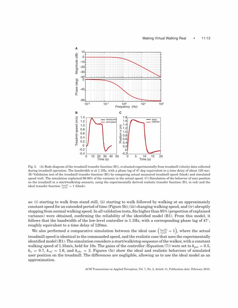
Fig. 5. (A) Bode diagram of the treadmill transfer function (B1), evaluated experimentally from treadmill velocity data collectedduring treadmill operation. The bandwidth is at 1.1Hz, with a phase lag of 47 deg (equivalent to a time delay of about 120 ms).(B) Validation test of the treadmill transfer function (B1) by comparing actual measured treadmill speed (black) and simulatedspeed (red). The simulation explained 99.06% of the variance in the actual speed. (C) Simulation of the behavior of user positionon the treadmill in a start/walk/stop scenario, using the experimentally derived realistic transfer function (B1, in red) and theideal transfer function vtm(s)
vC (s) = 1 (black).
as: (i) starting to walk from stand still, (ii) starting to walk followed by walking at an approximatelyconstant speed for an extended period of time (Figure 5b); (iii) changing walking speed, and (iv) abruptlystopping from normal walking speed. In all validation tests, fits higher than 95% (proportion of explainedvariance) were obtained, confirming the reliability of the identified model (B1). From this model, itfollows that the bandwidth of the low-level controller is 1.1Hz, with a corresponding phase lag of 47◦,roughly equivalent to a time delay of 120ms.
We also performed a comparative simulation between the ideal case(
vtm(s)vC(s) = 1
), where the actual
treadmill speed is identical to the commanded speed, and the realistic case that uses the experimentallyidentified model (B1). The simulation considers a start/walk/stop sequence of the walker, with a constantwalking speed of 1.35m/s, held for 10s. The gains of the controller (Equation (7)) were set to kpos = 0.5,ka = 0.7, kref = 1.6, and kobv = 3. Figures (5c) show the ideal and realistic behaviors of simulateduser position on the treadmill. The differences are negligible, allowing us to use the ideal model as anapproximation.
ACM Transactions on Applied Perception, Vol. 7, No. 2, Article 11, Publication date: February 2010.

11:14 • J. L. Souman et al.
REFERENCES
CATHERS, I., DAY, B. L., AND FITZPATRICK, R. C. 2005. Otholith and canal reflexes in human standing. J. Physiol. 563, 229–234.CHECCACCI, D., HOLLERBACH, J. M., HAYWARD, R., AND BERGAMASCO, M. 2003. Design and analysis of a harness for torso force
application in locomotion interfaces. In Proceedings of the EuroHaptics Conference. IEEE, Los Alamitos, CA, 53–67.CHRISTENSEN, R. R., HOLLERBACH, J. M., XU, Y., AND MEEK, S. G. 2000. Inertial-force feedback for the tread port locomotion
interface. Presence 9, 1, 1–14.DARKEN, R. P., COCKAYNE, W. R., AND CARMEIN, D. 1997. The omni-directional treadmill: A locomotion device for virtual worlds.
In Proceedings of the 10th Annual ACM Symposium on User Interface Software and Technology. ACM, New York, 213–221.DE LUCA, A., MATTONE, R., AND ROBUFFO GIORDANO, P. 2006a. The motion control problem for the CyberCarpet. In Proceedings
of the IEEE International Conference on Robotics and Automation. IEEE, Los Alamitos, CA, 3532–3537.DE LUCA, A., MATTONE, R., AND ROBUFFO GIORDANO, P. 2006b. Feedback/feedforward schemes for motion control of the Cyber-
Carpet. In Proceedings of the IEEE Symposium on Robot Control. IEEE, Los Alamitos, CA.DE LUCA, A., MATTONE, R., AND ROBUFFO GIORDANO, P. 2007. Acceleration-level control of the CyberCarpet. In Proceedings of the
IEEE International Conference on Robotics and Automation. IEEE, Los Alamitos, CA, 2330–2335.DURGIN, F. H., PELAH, A., FOX, L. F., LEWIS, J., KANE, R., AND WALLEY, K. A. 2005. Self-motion perception during locomotor
recalibration: More than meets the eye. J. Exp. Psych. Human Percept. Perform. 31, 3, 398–419.FERNANDES, K. J., RAJA, V., AND EYRE, J. 2003. Cybersphere: The fully immersive spherical projection system. Comm. ACM 46 ,
9, 141–146.FITZPATRICK, R. C., BUTLER, J. E., AND DAY, B. L. 2006. Resolving head rotation for human bipedalism. Curr. Biol. 16, 1509–1514.HOLLERBACH, J. M., XU, Y., CHRISTENSEN, R., AND JACOBSEN, S. C. 2000. Design specifications for the second generation Sarcos
Treadport locomotion interface. In Proceedings of the Haptics Symposium, ASME Dynamic Systems and Control Division.IEEE, Los Alamitos, CA,69–2, 1293–1298.
HUANG, J.-Y. 2003. An omnidirectional stroll-based virtual reality interface and its application on overhead crane training.IEEE Trans. Multimedia 5, 1, 39–51.
IWATA, H. 1999. Walking about virtual environments on an infinite floor. IEEE Virtual Reality, 286–293.JAHN, K., STRUPP, M., SCHNEIDER, E., DIETERICH, M., AND BRANDT, T. 2000. Differential effects of vestibular stimulation on walking
and running. NeuroReport 11, 8, 1745–1748.KRSTIC, M., KANELLAKOPOULOS, I., AND KOKOTOVIC, P. 1995. Nonlinear and Adaptive Control Design. John Wiley & Sons,
New York.LICHTENSTEIN, L., BARABAS, J., WOODS, R. L., AND PELI, E. 2007. A feedback-controlled interface for treadmill locomotion in virtual
environments. ACM Trans. Appl. Percept. 4, 1.MINETTI, A. E., BOLDRINI, L., BRUSAMOLIN, L., ZAMPARO, P., AND MCKEE, T. 2003. A feedback-controlled treadmill (treadmill-on-
demand) and the spontaneous speed of walking and running in humans. J. Appl. Physiol. 95, 838–843.MITTELSTAEDT, M.-L., AND MITTELSTAEDT, H. 2001. Idiothetic navigation in humans: Estimation of path length. Exp. Brain Res.
139, 318–322.MOGHADDAM, M. M., AND BUEHLER, M. 1993. Control of virtual motion systems. In Proceedings of the IEEE/RSJ International
Conference on Intelligent Robots and Systems. IEEE, Los Alamitos, CA, 63–67.MOHLER, B., THOMPSON, W. B., CREEM-REGEHR, S. H., WILLEMSEN, P., PICK, H. L., AND RIESER, J. J. 2007. Calibration of locomotion
due to visual motion in a treadmill-based virtual environment. ACM Trans. Appl. Percept. 4, 1.NAGAMORI, A., WAKABAYASHI, K., AND ITO, M. 2005. The ball array treadmill: A locomotion interface for virtual worlds. IEEE
Virtual Reality 3–6.NOMA, H., AND MIYASATO, T. 1998. Design for locomotion interface in a large scale virtual environment ATLAS: ATR locomotion
interface for active self motion. In Proceedings of the 7th Annual Symposium on Haptic Interface for Virtual Environments andTeleoperated Systems. IEEE, Los Alamitos, CA, 64, 111–118.
NOMA, H., SUGIHARA, T., AND MIYASATO, T. 2000. Development of ground surface simulator for Tel-E-Merge system. In Proceedingsof IEEE Virtual Reality Conference. IEEE, Los Alamitos, CA, 217–224.
PANTELEY, E., AND LORYA, A. 1998. On global uniform asymptotic stability of nonlinear time-varying systems in cascade. Syst.Control Lett. 33, 2, 131–138.
RIESER, J. J., PICK, H. L., ASHMEAD, D. H., AND GARING, A. E. 1995. Calibration of human locomotion and models of perceptual-motor organization. J. Exp. Psych. Human Percept. Perform. 21, 3, 480–497.
Received January 2008; revised October 2008; accepted February 2009
ACM Transactions on Applied Perception, Vol. 7, No. 2, Article 11, Publication date: February 2010.
Related Documents