2332-7782 (c) 2015 IEEE. Personal use is permitted, but republication/redistribution requires IEEE permission. See http://www.ieee.org/publications_standards/publications/rights/index.html for more information. This article has been accepted for publication in a future issue of this journal, but has not been fully edited. Content may change prior to final publication. Citation information: DOI 10.1109/TTE.2015.2437338, IEEE Transactions on Transportation Electrification 1 Abstract— In order to achieve lower fuel consumption and less greenhouse gas emissions, we need higher-efficiency vehicles with improved performance. Electrification is the most promising solution to enable a more sustainable and environmentally friendly transportation system. Electrified transportation vision includes utilizing more electrical energy to power traction and non-traction loads in the vehicle. In electrified powertrain applications, the efficiency of the electrical path and the power and energy density of the components play important roles to improve the electric range of the vehicle, to run the engine close to its peak efficiency point, and to maintain lower energy consumption with less emissions. In general, the electrified powertrain architecture, design and control of the powertrain components, and software development are coupled to facilitate an efficient, high-performance, and reliable powertrain. In this paper, enabling technologies and solutions for the electrified transportation are discussed in terms of power electronics, electric machines, electrified powertrain architectures, energy storage systems, and controls and software. Index Terms— Electric machines, electric vehicles, electrified powertrains, energy storage systems, energy storage, hybrid electric vehicles, plug-in hybrid electric vehicles, power electronics, transportation electrification, and vehicle control software. I. INTRODUCTION oday, mobility is one of the most important parameters to achieve economic growth and high standards of living. To enhance mobility, we need a reliable, inexpensive, clean, and, most importantly, sustainable transportation system. However, due to high dependence on fossil fuels as the main source of energy, our transportation system is not sustainable. Contributing to nearly one third of the total greenhouse gas (GHG) emissions, our transportation system is not environmentally friendly either. There are more than 900 million vehicles in use around the world today. More than 250 million of these vehicles are located in the United States. There is already 80 million vehicles manufactured every year worldwide and these numbers are expected to keep rising in next few decades, especially in Asia. The vast majority of these vehicles is powered solely by internal combustion engines (ICEs) and requires fossil fuels as the energy source. The carbon dioxide (CO 2 ) generated by burning fossil fuels is a major contributor to the GHG emissions [1]. In addition, even though there is a decreasing trend in the last few years, a significant portion of the oil used in the U.S. transportation system is still imported [2]. In order to create a sustainable and cleaner transportation system, we need higher-efficiency vehicles with significantly lower fuel consumption. In 2012, the U.S. government announced new fuel economy standards. They mandate that the average fuel economy of passenger cars and light-duty trucks in the United States has to rise to 54.5 mi/gal (4.3 L/100km) by 2025 [3]. These aggressive targets cannot be achieved solely by improving the ICE technology. The average efficiency of an ICE is less than 30% and most cars today can achieve only 10-20% overall efficiency. Alternatively, electric energy storage systems, electric machines, and power electronic converters can provide much higher efficiencies; therefore, electrification is the most promising solution to achieve the targets. Electrified transportation is a paradigm shift from conventional internal combustion engine based vehicles to more-efficient and cleaner electrified vehicles. The architecture of the powertrain, the design of the powertrain components, and the controls and software development are coupled with each other to maintain high-performance, high-efficiency, reliable, and affordable vehicles. In this paper, the critical components of electrified powertrains, including power electronics, electric machines, electrified powertrains, energy storage systems, and controls and software are discussed to achieve the transportation electrification vision. The available technologies, applications, solutions, and future trends are investigated. II. TRANSPORTATION ELECTRIFICATION Transportation electrification vision includes using more electrical energy to power propulsion and non-propulsion loads in vehicles. Conventionally, ICEs are not highly efficient and they can achieve an average efficiency of less than 30%. Electrical systems can however provide much higher efficiencies. Electric motors can be designed to operate with efficiency levels above 90% [4]. Furthermore, electrical systems are faster and can be controlled easily as compared to mechanical systems. In addition, electrical energy can be generated from many resources, such as wind, solar, and hydro, which are renewable and carbon free. Transportation Making the Case for Electrified Transportation Berker Bilgin, Member, IEEE, Pierre Magne, Member, IEEE, Pawel Malysz, Member, IEEE, Yinye Yang, Member, IEEE, Vera Pantelic, Matthias Preindl, Member, IEEE, Alexandre Korobkine, Weisheng Jiang, Student Member, IEEE, Mark Lawford, Senior Member, IEEE, and Ali Emadi, Fellow, IEEE T

Welcome message from author
This document is posted to help you gain knowledge. Please leave a comment to let me know what you think about it! Share it to your friends and learn new things together.
Transcript

2332-7782 (c) 2015 IEEE. Personal use is permitted, but republication/redistribution requires IEEE permission. Seehttp://www.ieee.org/publications_standards/publications/rights/index.html for more information.
This article has been accepted for publication in a future issue of this journal, but has not been fully edited. Content may change prior to final publication. Citation information: DOI10.1109/TTE.2015.2437338, IEEE Transactions on Transportation Electrification
1
Abstract— In order to achieve lower fuel consumption and
less greenhouse gas emissions, we need higher-efficiency
vehicles with improved performance. Electrification is the
most promising solution to enable a more sustainable and
environmentally friendly transportation system.
Electrified transportation vision includes utilizing more
electrical energy to power traction and non-traction loads
in the vehicle. In electrified powertrain applications, the
efficiency of the electrical path and the power and energy
density of the components play important roles to improve
the electric range of the vehicle, to run the engine close to
its peak efficiency point, and to maintain lower energy
consumption with less emissions. In general, the electrified
powertrain architecture, design and control of the
powertrain components, and software development are
coupled to facilitate an efficient, high-performance, and
reliable powertrain. In this paper, enabling technologies
and solutions for the electrified transportation are
discussed in terms of power electronics, electric machines,
electrified powertrain architectures, energy storage
systems, and controls and software.
Index Terms— Electric machines, electric vehicles, electrified
powertrains, energy storage systems, energy storage, hybrid
electric vehicles, plug-in hybrid electric vehicles, power
electronics, transportation electrification, and vehicle control
software.
I. INTRODUCTION
oday, mobility is one of the most important parameters to
achieve economic growth and high standards of living. To
enhance mobility, we need a reliable, inexpensive, clean, and,
most importantly, sustainable transportation system. However,
due to high dependence on fossil fuels as the main source of
energy, our transportation system is not sustainable.
Contributing to nearly one third of the total greenhouse gas
(GHG) emissions, our transportation system is not
environmentally friendly either.
There are more than 900 million vehicles in use around the
world today. More than 250 million of these vehicles are
located in the United States. There is already 80 million
vehicles manufactured every year worldwide and these
numbers are expected to keep rising in next few decades,
especially in Asia. The vast majority of these vehicles is
powered solely by internal combustion engines (ICEs) and
requires fossil fuels as the energy source. The carbon dioxide
(CO2) generated by burning fossil fuels is a major contributor
to the GHG emissions [1]. In addition, even though there is a
decreasing trend in the last few years, a significant portion of
the oil used in the U.S. transportation system is still imported
[2].
In order to create a sustainable and cleaner transportation
system, we need higher-efficiency vehicles with significantly
lower fuel consumption. In 2012, the U.S. government
announced new fuel economy standards. They mandate that
the average fuel economy of passenger cars and light-duty
trucks in the United States has to rise to 54.5 mi/gal (4.3
L/100km) by 2025 [3]. These aggressive targets cannot be
achieved solely by improving the ICE technology. The
average efficiency of an ICE is less than 30% and most cars
today can achieve only 10-20% overall efficiency.
Alternatively, electric energy storage systems, electric
machines, and power electronic converters can provide much
higher efficiencies; therefore, electrification is the most
promising solution to achieve the targets. Electrified
transportation is a paradigm shift from conventional internal
combustion engine based vehicles to more-efficient and
cleaner electrified vehicles. The architecture of the powertrain,
the design of the powertrain components, and the controls and
software development are coupled with each other to maintain
high-performance, high-efficiency, reliable, and affordable
vehicles.
In this paper, the critical components of electrified
powertrains, including power electronics, electric machines,
electrified powertrains, energy storage systems, and controls
and software are discussed to achieve the transportation
electrification vision. The available technologies, applications,
solutions, and future trends are investigated.
II. TRANSPORTATION ELECTRIFICATION
Transportation electrification vision includes using more
electrical energy to power propulsion and non-propulsion
loads in vehicles. Conventionally, ICEs are not highly
efficient and they can achieve an average efficiency of less
than 30%. Electrical systems can however provide much
higher efficiencies. Electric motors can be designed to operate
with efficiency levels above 90% [4]. Furthermore, electrical
systems are faster and can be controlled easily as compared to
mechanical systems. In addition, electrical energy can be
generated from many resources, such as wind, solar, and
hydro, which are renewable and carbon free. Transportation
Making the Case for Electrified Transportation
Berker Bilgin, Member, IEEE, Pierre Magne, Member, IEEE, Pawel Malysz, Member, IEEE, Yinye
Yang, Member, IEEE, Vera Pantelic, Matthias Preindl, Member, IEEE, Alexandre Korobkine,
Weisheng Jiang, Student Member, IEEE, Mark Lawford, Senior Member, IEEE, and Ali Emadi,
Fellow, IEEE
T

2332-7782 (c) 2015 IEEE. Personal use is permitted, but republication/redistribution requires IEEE permission. Seehttp://www.ieee.org/publications_standards/publications/rights/index.html for more information.
This article has been accepted for publication in a future issue of this journal, but has not been fully edited. Content may change prior to final publication. Citation information: DOI10.1109/TTE.2015.2437338, IEEE Transactions on Transportation Electrification
2
electrification is an evolving paradigm shift from non-
sustainable Transportation 1.0 of conventional vehicles to
more sustainable Transportation 2.0 of electrified vehicles [5].
A. Degree of Electrification
Electrification in automobiles can occur both in propulsion
and non-propulsion loads. The electrification level for the
given vehicles defines the ratio of electrical power available to
the total power. Fig. 1 shows the fuel efficiency improvement
on the same vehicle platform for different electrification
levels. Today, most of the vehicles being manufactured have
10-20% of electrification. These more-electric vehicles
(MEVs) employ electrified non-propulsion loads, such as
electrically assisted power steering, electrically driven air
conditioning, pumps, fans, and so on. Mild hybrids have a
higher degree of electrification and they provide auto
start/stop function, regenerative braking capability, and some
use of electric power for propulsion. Depending on the system
requirements, integration complexity, and cost, mild hybrids
can be designed as low voltage or high voltage systems. This
typically provides between 8-15% improvements in fuel
efficiency. By 2017, 70% of the new vehicles are expected to
have start/stop function in Europe [6].
Deg
ree
of e
lect
rific
atio
n (%
)
Fuel efficiency improvement
Start/stop
Micro hybrid
LV mild hybrid
HV mild hybrid
Full hybrid
BEV
PHEV
0
100 100 kW
100%
40-1
00%
20-5
0%
12-2
0%
8-15
%
3-10
%
2-5%
30-80 kW
20-50 kW
12-20 kW
3-7 kW
3-10 kW
8-15 kW
Fig. 1. Degree of electrification: typical fuel efficiency improvement and electric traction motor power [7].
Full hybrid electric vehicles (HEVs) have a higher degree of
electrification. Depending on the design of the powertrain, full
hybrids can achieve 20-50% and more reduction in fuel
consumption [7]. In power-split hybrids, two electric motors
are coupled with an engine to create an electrically variable
transmission. The design of the powertrain defines the fuel
efficiency improvement in city and highway driving
conditions.
By 2013, 3 million hybrids were sold in the United States.
Around 1.4 million of these vehicles were Toyota Prius, which
is a power-split hybrid and it provides a balanced city and
highway fuel efficiency. Ford Fusion Hybrid is also a power-
split hybrid and it constituted around 8% of the hybrid sales in
the United States. Hyundai Sonata Hybrid has a simpler
design and it employs one main traction motor and one
integrated starter-generator. It provides high fuel economy in
the highway driving conditions, because the engine operates
with a higher efficiency and electric motor provides torque
assist when higher power is required. Hyundai Sonata Hybrid
had around 4.5% of the total hybrid sales in the United States
in 2013 [8].
By increasing the degree of electrification, a higher fuel
efficiency can be gained. Plug-in hybrid electric vehicles
(PHEVs) and extended-range electric vehicles (EREVs) have
larger battery packs; therefore, they can provide a longer all-
electric drive with plug-in charging. In the United States,
about 85% of the vehicles are driven less than 100km a day.
Therefore, PHEVs are very attractive. In an EREV, the
powertrain topology looks more like a series hybrid and the
engine runs the generator to supply electric power to the
traction motor. GM’s Chevy Volt is an example; but, the
engine can still propel the wheels through a coupling
mechanism. Between December 2010 and March 2014, Chevy
Volt sold around 60K units in the Unites States [9].
In all-electric vehicles (EVs), the traction power is supplied
solely from an electric motor and an electric energy storage
system. One of the main concerns in EVs is the limited driving
range, which is dependent on the energy density of the battery
cells and also the temperature [10]. Today, there are many
electric vehicles available on the market, such as Nissan Leaf,
Fiat 500e, and Ford Focus Electric. Between December 2010
and March 2014, Nissan Leaf sold around 47K units in the
United States and it has a 24kWh battery pack. Tesla Model S
is a higher-performance electric vehicle and sold around 25K
units in the United States since March 2014. It offers options
of either a 60 kWh or 85 kWh battery pack, which provide a
much longer driving range.
Com
bine
d fu
el e
cono
my
ratin
g (E
PA
MP
G)
Car size (Square feet, wheelbase × track width)
25 30 35 40 45 50 55 60 65 70
20
10
40
30
60
50
2025
2021
2016
Toyota Prius CToyota Prius
100
110Smart for two Electric Drive
Nissan Leaf
Chevrolet Volt (EV mode)
Chevrolet Volt (Extended range)
Audi Q5 Hybrid
Rolls-Royce Phantom EWBAudi S8
Mazda 6Ford Fiesta ST
Honda Accord Hybrid
Honda Civic Hybrid
BMW ActiveHybrid 3Chevrolet Malibu Hybrid
Infinity Q70 Hybrid
Toyota Camry Hybrid LE
Hyundai Sonata Hybrid
Honda Accord Hybrid
Mercedes-Benz E400 Hybrid
Toyota CamryFord 150
Conventional vehicle
Electrified vehicle
Fig. 2. Fuel economy targets and current status of vehicles.
In the next decade and beyond, the electrification level in all
new vehicles will need to increase to meet the fuel economy
requirements, which for example mandate a fuel economy
equivalent to 54.5 mpg by 2025 in the United States for light
duty vehicles. Fig. 2 shows the fuel economy status of some of
the current electrified vehicles and conventional vehicles with
respect to the fuel-efficiency standards. With the new
regulations, 12 billion barrels of reduction in oil consumption,
$1.7 trillion cost saving and 6 billion metric tons of GHG
emission reduction is estimated [11]. This will create a more
sustainable and environmentally friendly transportation system
that produces lower emissions.

2332-7782 (c) 2015 IEEE. Personal use is permitted, but republication/redistribution requires IEEE permission. Seehttp://www.ieee.org/publications_standards/publications/rights/index.html for more information.
This article has been accepted for publication in a future issue of this journal, but has not been fully edited. Content may change prior to final publication. Citation information: DOI10.1109/TTE.2015.2437338, IEEE Transactions on Transportation Electrification
3
III. POWER ELECTRONICS
In electrified vehicles such as HEVs, PHEVs, and EVs,
power electronic circuits act as the connection between the
energy sources, e.g., battery pack, and the power actuators,
i.e., traction motors. They convert, transform, and transfer
electrical power through the powertrain. One of the main
advantages of the power electronic systems is that they can be
bidirectional and provide high efficiency (>90%). However,
they require complex design and manufacturing process due to
their multidisciplinary nature including electrical, thermal,
mechanical, control, software, and magnetic aspects.
Electric Machine B
Electrical power flow: charging of the battery from ICE
Mechanical power flow to and from wheels
Mechanical power flow from ICE
Cha
rger
Plug-in configuration
only
AC
grid
Electrical power flow: traction from battery and regenerative braking
Electrical power flow: electric traction from ICE (series operation)
Dri
ve S
yste
m A
(O
pti
on
al:
HE
V &
PH
EV
)
Bat
tery DC-DC
boost (optional) In
vert
er B
Electric Machine A
Inve
rter
A
AP
M
12 V
ICE
Dri
ve
Sys
tem
B
Fig. 3. A typical electrified propulsion system architecture.
Converters used in electrified propulsion systems are
different depending on the powertrain. Fig. 3 shows a typical
architecture for electrified propulsion system architecture and
Table I summarizes the configurations used in different
vehicles on the market. In some configurations, a dc-dc boost
converter is used between the battery pack and the drive
system to step-up the voltage. This offers more flexibility for
selecting the voltage rating of the battery pack and the motor,
as well as for controlling the system [12]. However, this
requires development and implementation of an additional
converter and brings additional cost.
Table I. Power electronic configurations in different vehicles.
Module Battery dc-dc
boost
Drive
System B
Drive
System A
Charger
Toyota SDS II
Ford Fusion
Hybrid
Hyundai
Sonata Hybrid
Chevrolet
Volt
Nissan Leaf
Ford Focus
Electric
As depicted in Fig. 4, a power converter is a system made
by several components. Power switches, cooling system,
capacitor, coils, sensors, control board, and housing are the
major ones. All of these components interact together in order
to achieve electrical power conversion in an effective,
efficient, and reliable way. Functionality, volume, and cost of
these components affect the characteristics and performance of
the converter.
A. Power Switches
For automotive applications, two types of switches are
mainly used: Insulated Gate Bipolar Transistor (IGBT) for
systems rated between 200-1200V, and Metal Oxide
Semiconductor Field Effect Transistor (MOSFET) for
converters rated at a lower voltage, such as in 12V or 48V
systems. Semiconductors are available in standardized
packages containing 1 (Discrete), 2 (Dual), 4 (Fourpack), or 6
(Sixpack) switches. Moreover, for large-scale applications,
custom configurations can be developed to achieve specific
functionality and higher power density. This is what has been
developed by Toyota in the Synergy Drive System II (SDS II)
where 14 IGBTs and Diodes have been placed in the same
module to achieve functionalities of the two inverters and the
dc-dc boost converter [13].
ControllerMCU, DSP, FPGA, ASIC, etc.
Gate DriverOpto-coupler
SensorsVoltage, current, temperature, etc.
Power CircuitryPower Switches: MOSFET, IGBT, Diode, etc.
Cooling SystemLiquid cooled: cold plate, pumps
Air cooled: heat sink, fans
MagneticsInductor, Transformer, etc.
Coo
lant
(ai
r, o
il,
ethy
l-wat
er)
Ele
ctric
al
pow
er fl
ow
Mech
anical S
tructu
reB
usbar, packaging, enclosure
Powertrain level commandCAN bus: torque, speed, voltage, current demand, etc.
Data for vehicle/powertrain monitoring and demand; CAN: torque, speed, voltage, current demand, etc.
Inte
rnal
con
trol
sig
nals
flow
Fig. 4. Power converter structure.
In the last decade, wide-band gap devices based on Silicon
Carbide (SiC) or Gallium Nitrate (GaN) have been developed
to improve the performance of power converters. As compared
to silicon based switches, SiC devices offer improved
switching characteristics, better thermal properties, and higher
voltage operation. Lower switching losses and high thermal
conductivity reduce the cooling requirements and increase the
efficiency [14]-[15]. Wide-band gap technologies can yield
significant reduction in the size of the capacitors and inductors
due to their capability of switching at higher frequency. This
increases the power density of the converter.
Toyota and Denso have developed a SiC based drive unit.
They increased the switching frequency 10 times and managed
to reduce the overall volume of the drive unit by 80% as
compared to their existing converter [16]. From a vehicle
point of view, Toyota observed an increase in fuel economy of
more than 5% under the JC08 test cycle [17]. In addition, a
study published in 2011 with the Oak Ridge National
Laboratory estimated an increase of 14.7% of the fuel
economy of a Toyota Prius 2004 for the UDDS drive cycle
with the use of SiC components [18]. Although these numbers
are very promising, by the time of the writing, there was no
commercially available vehicle using this technology. This
was mainly due to the relatively high cost associated with the
wide-band gap devices. However, with the increase in the

2332-7782 (c) 2015 IEEE. Personal use is permitted, but republication/redistribution requires IEEE permission. Seehttp://www.ieee.org/publications_standards/publications/rights/index.html for more information.
This article has been accepted for publication in a future issue of this journal, but has not been fully edited. Content may change prior to final publication. Citation information: DOI10.1109/TTE.2015.2437338, IEEE Transactions on Transportation Electrification
4
number of suppliers, off-the-shelf availability, rising
production, and reducing prices, the market share for wide-
band gap devices is expected to grow [19].
B. Passive Components
Capacitors and magnetic components are the major passive
components in a power converter. Capacitors have an
important role as they contribute to the power quality of the
converter by filtering input and output currents. In particular,
they prevent current ripple from reaching the battery. In lower
voltage applications such as auxiliary power unit (APU) with
12V output and also in 48V mild hybrids, electrolytic
capacitors are widely used. Film capacitors are usually the
preferred option for the high voltage dc-link in HEVs, PHEVs,
and EVs. Film capacitors are utilized in 2012 Nissan Leaf,
2012 Hyundai Sonata Hybrid, and Toyota SDS II [20].
Power inductors (e.g., in boost converters and battery
chargers), high-frequency transformers (e.g., in auxiliary
power converters), and chokes (e.g., EMI filters) are among
the major magnetic passive components. The design of the
magnetic component and the core material has significant
importance in the size and efficiency. For transformers
operating at high frequency (hundreds of kHz), ferrite is often
preferred due to its low cost and low core losses. However, the
low saturation flux density of ferrite leads to a bulky design in
high power applications. For power inductors, materials with
higher saturation flux density, such as iron powder or silicon
steel, are preferred.
C. Cooling System
Cooling system is one of the most important components
for reliability and power density of power converters. It
prevents components operating at a harmful temperature. For
power switches and passive components, the heat generated by
the losses has to be evacuated from the module or the
component first and then, from the converter. For low-power
applications, forced air cooling can be used. In high-power
applications, such as traction inverters, liquid cooling is
preferred due to its better heat dissipation capability. This
enables higher power density.
To improve the cooling performance of switches, more and
more features are integrated in the power modules [21]-[22].
Pin-fin technology is an example, which is utilized by
Infineon. It offers a direct contact between the coolant and the
baseplate of the module, which yields up to 50% reduction in
thermal resistance between the chip and the coolant [23].
D. Challenges for Traction Power Electronics
U.S. Department of Energy has defined 2020 targets for
power density (13.4 kW/L) and cost (3.3 $/kW) for traction
power converters. The current power density values of some
traction inverters are given in Fig. 5. It can be observed that
prototype SiC inverters can exceed 2020 targets in terms of
power density. But these prototypes still do not meet the cost
targets. Other converters using Si technology also offer high
power density, but they cannot sustain a coolant temperature
of 1050C defined by the targets. This shows that cooling
system and thermal limitation of switches are key challenges
for power electronics.
One of the biggest challenges for the next generation of
automotive power electronic system will be reducing the cost
to provide more affordable solutions. Among possible
methods to reach this goal are improvements in the
manufacturing process, design scalability, and development of
more integrated components and systems, such as the smart
power module concept [24].
Power converters are made up of many different
components with different sizes and mechanical properties.
They vary from small and fragile electronic chips to bulky
magnetic components and cold plates. Interactions between
components and their operating conditions are so tight that an
improvement at any level (e.g., switching frequency, cooling,
current density, magnetic flux density, etc.) can yield an
overall enhancement of the entire design. This can be
observed in SiC based technologies which enable higher
switching frequency and reduced cooling requirements.
Prius 2004 [10]
2002 2004 2006 2008 2010 2012 20140
20
10
40
30
50
60
Year
Pow
er d
ensi
ty (
kW/L
)
Denso – Toyota*** [26]
Prius 2010 [13], [27]
Lexus LS 600h [13], [27]Camry 2007 [13], [27]
Nissan Research Center*** [25]
13.4 kW/L, DOE 2020 Target**
PM100DX, Rinehart Motion Systems*
* Maximum coolant temperature = 85ºC** Maximum coolant temperature = 105ºC*** Air Cooled
Fig. 5. Power densities of existing traction inverter products/prototypes.
IV. ELECTRIC MACHINES
In electrified powertrains, the efficiency and performance of
the electric machines have a significant impact on the fuel
consumption, acceleration, high-speed performance, and
driving comfort. More efficient and higher performance
electric traction motors improve the use of electrical mode
and, hence, in hybrids, this helps to run the engine closer to its
peak efficiency areas leading to lower fuel consumption and,
in EVs, this facilitates higher all-electric range.
Rotor rotational speed (rpm)
Out
put t
orqu
e (N
m)
Constant speed region
Constant power region
Base speed
Maximum speed
UDDS, auto-start, peak torque
High-grade reversing
Hwy continuous, electric mode
0-60 mph, engine on, 10 sec
High-spped, 2% gradability, engine on, continuous
High-speed, auto-start
45-65 mph, engine on
Peak power point
Fig. 6. Typical torque-speed characteristics and most frequent operating points
of an electric traction motor in a hybrid electric powertrain.

2332-7782 (c) 2015 IEEE. Personal use is permitted, but republication/redistribution requires IEEE permission. Seehttp://www.ieee.org/publications_standards/publications/rights/index.html for more information.
This article has been accepted for publication in a future issue of this journal, but has not been fully edited. Content may change prior to final publication. Citation information: DOI10.1109/TTE.2015.2437338, IEEE Transactions on Transportation Electrification
5
Electric traction motors have stringent operational
requirements. Fig. 6 shows the typical torque-speed
characteristics and most frequent operating points of an
electric traction motor. The electric motor is required to
deliver high torque at lower speeds for quick acceleration, hill
climbing, engine auto-start, and reversing at high road
gradient. It is also required to operate at medium speed range
for city driving and, at high-speed range, for highway driving
conditions. A traction motor needs to provide high efficiency
at its most frequent operating points to improve the powertrain
efficiency and reduce fuel consumption.
In addition to the vehicle platform, engine size, drive
cycles, volume, weight, and lifetime and cost constraints,
various other parameters including the torque-speed
characteristics, peak-power requirements, and thermal,
structural, and noise-vibration-harshness (NVH) conditions
define the selection of the right electric machine for the
application. For example, in mild hybrids or belt-driven
starter-generators (BSG), the maximum torque envelope of the
electric motor should cover the cranking speed of the engine
multiplied by the pulley ratio. In addition, since the motor is
located under the hood, a BSG motor should be designed to
operate at high-temperatures (105-115 0C) and in high-
vibration (20 G or more) environment [7]. This affects the
machine design process from the selection of the core and
insulation material, use of permanent magnets and permanent
magnet type, manufacturing process, to defining the number
of poles, winding configuration, and so on.
A. Interior Permanent Magnet Synchronous Machine
Interior permanent magnet synchronous machine (IPMSM)
is used in most of the hybrid and electric vehicles currently
available on the market. As shown in Fig. 7(a), IPMSM has
permanent magnets embedded inside the rotor, which provides
an independent excitation source. For this reason, IPMSM can
provide high torque density and better efficiency especially at
low and medium speed ranges.
The selection and configuration of the permanent magnets
have significant effect on the output torque of the machine.
Toyota Prius is a power-split hybrid and its traction motor is
connected to the final drive over the ring gear. The motor is
designed to deliver a peak power of 60kW with a maximum
torque of 207 Nm and a maximum speed of 13,500 rpm,
which corresponds to 110 mph vehicle speed. The V-shape
configuration of the magnets provides saliency and, hence,
additional reluctance torque component, which facilitates field
weakening and helps with extending the speed range [13]. In
IPMSM, the configuration of the permanent magnets is highly
dependent on the torque-speed requirements. For example,
2011 version of Nissan Leaf traction motor was designed for a
peak power of 80 kW with a maximum torque of 280 Nm and
a maximum speed of 10,390 rpm. This motor has a delta-
shape magnet [28]. Chevrolet Spark traction motor has 105
kW peak power with a maximum torque of 540 Nm and a
maximum speed of 4,500 rpm. This motor has double-barrier
rotor geometry with bar-wound windings to enable higher
torque at low speeds [29].
In permanent magnet (PM) traction motors, high-energy
rare-earth permanent magnets are used to provide higher
torque density. The main disadvantages of PM machines are
the sensitivity of rare-earth magnets to temperature and their
high cost. For example, when the temperature of the magnet
increases to 160 0C, the output torque of the motor can drop by
up to 46% [30]. When designing an IPMSM, maximum
temperature and demagnetization should be taken into account
to define the size and volume of the magnet to optimize the
cost and performance.
B. Induction Machine
In an induction machine (IM), the magnetic field generated
by the stator currents induces voltage on the rotor conductors
and the rotor currents create torque. As shown in Fig. 7(b),
rotor is made of conducting bars which are die-casted in the
slots. As compared to IPMSM, IM operates at a lower power
factor with lower efficiency at low speeds due to the lack of
independent rotor excitation. One of the main disadvantages of
IM is the inherent rotor copper losses. Especially during high-
torque operation, heat generated by the rotor copper losses can
be difficult to extract. This puts a limit in the torque-density of
IM [31]. Stator Winding
Rotor
Permanent magnets
(a)
Stator Winding Rotor
(c)
Stator
Rotor
Rotor bars
(b)
Winding
Fig. 7. Typical electric machine types for traction applications: (a) interior permanent magnet synchronous machine, (b) induction machine, and (c)
switched reluctance machine.
Tesla EV has a 310 kW four-pole induction machine, which
provides 600 Nm of peak torque and a maximum speed of
14,000 rpm. The high-torque and high-speed operation with
IM is achieved by using copper rotor bars and by the
improvements in the mechanical design (e.g., high-strength
alloy steels and ceramic bearings). Copper has 60% higher
conductivity than aluminum. Therefore, copper rotor bars have
lower resistance and, hence, generate less heat at high
currents. However, copper has higher density than aluminum.
Therefore, die-casting of copper requires higher temperature
and high tonnage presses. This results in significant stress on
the rotor laminations and makes the manufacturing process
more challenging. Furthermore, the cost of copper die-casted

2332-7782 (c) 2015 IEEE. Personal use is permitted, but republication/redistribution requires IEEE permission. Seehttp://www.ieee.org/publications_standards/publications/rights/index.html for more information.
This article has been accepted for publication in a future issue of this journal, but has not been fully edited. Content may change prior to final publication. Citation information: DOI10.1109/TTE.2015.2437338, IEEE Transactions on Transportation Electrification
6
rotor is significantly higher than aluminum die-casted one
[31].
C. Switched Reluctance Machine
As compared to IPMSM and IM, switched reluctance
machine (SRM) has the simplest, most robust, and the lowest
cost structure. As shown in Fig. 7(c), SRM rotor has a salient
pole structure made of laminated silicon steel. It does not have
conductors or permanent magnets. The stator of SRM also has
a salient pole structure and concentrated coils are wound
around the poles. Therefore, SRM is very suitable to operate at
high speeds and high temperature conditions.
In SRM, torque production is based on the change of
magnetic reluctance. Since the relative position of the salient
poles defines the length of the airgap, torque is dependent on
the rotor position. The main disadvantage of conventional
SRM is significant torque ripples. In addition, strong radial
forces can excite the stator and this causes vibration and
acoustic noise. These factors can be a limitation in the power
density of conventional SRM. But, the rugged, simple, and
low-cost construction of SRM makes it a significant candidate
for electrified transportation in the long run. Using advanced
design and control techniques, torque ripples, noise, and
vibration in SRM can be reduced [32]-[34].
Currently, SRM is not used in any of the major hybrid or
electric on-road passenger cars on the market as the traction
motor. However, John Deere has utilized SRM in their hybrid
loaders as in-wheel traction motors. Four wheel-hub SRM
traction motors are used in the 944 Hybrid Loader
architecture. They are powered by two interior permanent
magnet generators that are driven by a 600 HP, 13.5 L Deere
diesel engine [35].
V. ELECTRIFIED POWERTRAINS
Electrified powertrains differ from conventional
powertrains in terms of on-board vehicle power paths and
transmission configurations, which integrate electric power
systems including power electronics, electric machines,
battery pack, and control units into vehicle platforms.
Compared to the conventional powertrains where engine is the
only power source, electrified powertrains add an electric
power path to assist or replace the conventional mechanical
power path. In hybrid and plug-in hybrid vehicles, the electric
power path intermingles with mechanical power path through
transmission integration, while in electric vehicles the electric
power path works exclusively to provide all the power for
traction and auxiliary loads. Typically, higher degrees of
electrification represent larger electrical power path ratio and,
thus, lead to lower fuel consumptions and less tailpipe
emissions.
A. Parallel Hybrids
One of the most widely used hybrid architecture is the
parallel hybrid configuration. It has been the powertrain of
choice for many auto manufacturers as one of their first steps
into the vehicle electrification due to its simple but effective
fuel-saving powertrain design. Up to date, a dozen of major
auto brands including Acura, Audi, BMW, Buick, Chevrolet,
Honda, Infinity, Mercedes, Nissan, Porsche, and Volkswagen
have released hybrid models in North America for a wide
range of vehicle classes based on parallel hybrid configuration
[36]. The parallel architecture consists of an electric machine
placed alongside with the ICE. Depending on the location of
the electric machine, either an integrated motor assist (IMA)
configuration such as in Honda Civic Hybrid, a BSG
configuration such as Chevrolet Malibu Hybrid, or a parallel-
through-the-road configuration can be formed. The electric
machine provides assistance to the engine for greater
acceleration and performance, or provides regenerative
braking during vehicle deceleration. For the IMA and BSG
configurations (mild hybrids), it provides auto-start function to
crank the engine and generate power for the vehicle auxiliary
loads replacing the original alternator.
Differential gear
Drive wheels
R
C
S
MG2ICE
C
R
S
ICE: Internal combustion engine
S: Sun gear
R: Ring gear
C: Carrier
Machine 1
Machine 2
Fig. 8. Toyota Prius hybrid synergy drive system.
B. Full Hybrids
Full hybrid powertrains with higher degrees of
electrification have been developed and many architecture
varieties have been evolved with great commercial success.
The power-split system is an input-split hybrid transmission,
which utilizes power split devices, i.e., planetary gear sets, at
the input side of the transmission that connects the engine and
electric machines. The planetary gear set splits the engine
power into different mechanical and electric power ratio and
achieves variable transmission output speed and torque. One
example of the power-split system is shown in Fig. 8, which
illustrates the 2010 Toyota Prius Hybrid Synergy Drive
system [13]. Variations of the power-split transmissions have
been applied to other models and brands such as Ford C-Max
Hybrid, Lincoln MKZ Hybrid, Lexus RX450h, Lexus LS600h,
Toyota Camry Hybrid, Toyota Highlander, etc.
ICE: Internal combustion engine
T: Transmission Differential gear
ICEMachine 1 Machine 2 T
Clutch
(a)
Differential gear
Drive wheels
Machine 1
Machine 2 T
(b)
Clutch
MG2Gear
MG2ICE
MG2Gear
Fig. 9. Series-parallel hybrid powertrain configurations: (a) Hyundai Sonata Hybrid /Kia Optima Hybrid series-parallel configuration and (b) Honda
Accord Hybrid series-parallel configuration.
Two-mode hybrid is another electrified powertrain that
incorporates the engine, electric machines, and mechanical

2332-7782 (c) 2015 IEEE. Personal use is permitted, but republication/redistribution requires IEEE permission. Seehttp://www.ieee.org/publications_standards/publications/rights/index.html for more information.
This article has been accepted for publication in a future issue of this journal, but has not been fully edited. Content may change prior to final publication. Citation information: DOI10.1109/TTE.2015.2437338, IEEE Transactions on Transportation Electrification
7
gear sets in a compound two-mode hybrid system. Similar to
the power-split system, the two-mode hybrid transmission
takes advantage of the planetary gear sets to integrate the
mechanical power path with the electric power path. However,
two-mode hybrid provides more operating modes when
compared to the Toyota power-split system by coordinating
the electric machines, clutches, and brakes while utilizing
multiple planetary gear sets [37].
In addition, the series-parallel hybrid is an alternative
architecture that uses direct mechanical connection to split the
transmission power flow instead of using planetary gear sets.
In this architecture, one of the machines is always connected
to the engine to function as both a starter motor and generator.
A second machine acts as the main traction motor and is
separated from the engine and generator by a clutch, which
enables multiple modes such as electric-only operation, series
operation, and series-parallel operation. Fig. 9 illustrates two
configurations of the series-parallel hybrid, where (a) is used
by Hyundai Sonata Hybrid and Kia Optima Hybrid and (b) is
used by Honda Accord Hybrid.
C. Plug-in Hybrids and Electric Vehicles
Plug-in hybrid electric vehicles (PHEV) and extended range
electric vehicles (EREV) contain even higher degrees of
electrification levels. They are equipped with larger battery
capacities that are capable of operating on battery power alone
for a considerable range and they can be charged directly from
the grid. Conventional engines are still employed to provide
power assist or used as the secondary power source. Charge
depleting, charge sustaining, and all-electric driving modes are
available depending on the state-of-charge of the energy
storage system and the control strategy. One example of an
EREV powertrain is the Chevrolet Volt as illustrated in Fig.
10. Two electric drive modes and two range extended modes
are available by engaging different combinations of the
clutches suited for various torque and speed requirements
from the road.
Clutch 1
Drive wheels
R
C
S
ICE: Internal combustion engine
S: Sun gear
R: Ring gear
C: CarrierMachine 2
Clutch 2Clutch 3
Machine 1MG2ICE
Differential gear
Fig. 10. Chevrolet Volt powertrain configuration.
Finally, electric vehicle powertrains employ the highest
electrification level and the simplest powertrain configuration
in which electric machine(s) directly drive the wheels via a
fixed gear reduction. Highest degrees of fuel displacement and
emissions reduction can be achieved while less mechanical
maintenance is required compared to the conventional vehicle
powertrains. Brand-new powertrain platforms are created such
as Tesla Model S and Nissan Leaf along with powertrains
evolved from existing conventional models such as Chevrolet
Spark EV and Ford Focus Electric.
Fig. 11 compares different electrified powertrains along
with the conventional ICE-based powertrain in terms of
electrification degree, fuel economy, emissions, and
powertrain complexity. It can be observed that all the
electrified powertrains provide increased fuel economy and
reduced emissions over the conventional one. Powertrains
with higher degrees of electrification such as EREV, PHEV,
and EV achieve the highest fuel economy gains, while typical
mild hybrids with parallel powertrain configuration achieve a
fuel efficiency improvement without substantially changing
the powertrain complexity. On the other hand, full hybrids
including power-split, two-mode, and series-parallel
powertrains require significant powertrain modification and
system integration. Especially in the case of two-mode hybrid,
the powertrain complexity is high [36]. It is apparent that EVs
have the highest fuel economy and the lowest powertrain
complexity. Batteries with high energy and power densities,
fast recharging time, and long-lasting life cycles are desired in
EVs.
Parallel
Power-split
Two-mode
Series-parallel
EREV
PHEV
Conventional
EVHighLow
Low
Hig
h
High Low
Low
High
Low
High
High
Low
High
Low
High
Low
Powertrain complexityFuel economyEmissions
Electrification degree
Fig. 11. Electrified powertrain architecture comparisons.
VI. ENERGY STORAGE SYSTEMS
Traditionally, electrical energy storage for vehicle
applications has been limited to starting/lighting/ignition (SLI)
subsystems. The increase in vehicle electrification has led to
an increase in the energy, power, and cycling requirements of
the vehicle energy storage system (ESS). This has enabled not
only efficient electric mobility, but also maintains faster
response along with secondary conveniences such as at-home
charging, vehicle-to-home (V2H) backup power, upcoming
vehicle-to-grid (V2G) infrastructure support, and the wireless
charging. Fuel efficiency can generally be increased with a
greater vehicle ESS by enabling greater use of more-efficient
electric drive. A variety of ESS solutions are available that are
dependent on the vehicle platform and its degree of
electrification. These factors impact the choice of energy
storage technology, its integration in the vehicle, and the
design of the energy management system (EMS).
The EMS comprises the raw energy storage technology, its
electronic, thermal, and control hardware and software. The
EMS controls and manages the ESS to deliver the electrical
2332-7782 (c) 2015 IEEE. Personal use is permitted, but republication/redistribution requires IEEE permission. Seehttp://www.ieee.org/publications_standards/publications/rights/index.html for more information.
This article has been accepted for publication in a future issue of this journal, but has not been fully edited. Content may change prior to final publication. Citation information: DOI10.1109/TTE.2015.2437338, IEEE Transactions on Transportation Electrification
8
power and energy requirements in a safe and efficient manner.
For systems that employ batteries, the EMS is the battery
management system (BMS). The EMS or BMS needs to
interconnect many cells, estimate BMS/EMS states, diagnose
fault conditions, report power and energy availability, and
communicate with other vehicular systems such as on-
board/off-board charger, infotainment, and traction control
systems.
A. Battery Technologies
The different energy storage technologies are graphically
compared in Fig. 12. Flooded lead-acid (FLA) cells are
commonly used for SLI batteries. The cell voltage is typically
2.17-2.22V [38]. FLA technology is very mature and highly
recyclable, but has limited cycle-life and depth-of-discharge.
Enhanced flooded lead-acid (EFLA) batteries typically have
double cycle-life to that of FLA making them suitable for the
most basic start-stop hybrid platforms [39]. For increased
power and cycle-life, sealed lead-acid (SLA), also called valve
regulated lead-acid (VRLA) batteries are available. Compared
to FLA, they have approximately 3.5 times higher cycle-life
and a slightly higher cell voltage of about 2.25V. This enables
them to handle small amounts of traction and regenerative
braking energy. VRLA technology is less mature and more
costly as compared to EFLA.
0 50 100 150 200 2500
200
400
600
800
1000
1200
0
1000
2000
3000
4000
5000
Cos
t ($/
kWh)
Specific energy (Wh/kg)
Spec
ific p
ower
(W/k
g)
Target
Lead Acid
NiMH
Na-Ni-Cl
Li-ion Power
Li-ion Energy
EDLC
Fig. 12. Cost augmented 3D Ragone diagram.
Nickel Metal Hydride (NiMH) batteries have been used in
HEVs for more than 15 years. The two main cell
manufacturers are PEVE and Sanyo Electric (Panasonic). The
technology is relatively mature and has shown longevity in
vehicles such as the Toyota RAV4 EV operating after a
decade and over 160,000 km [40]. The cells are manufactured
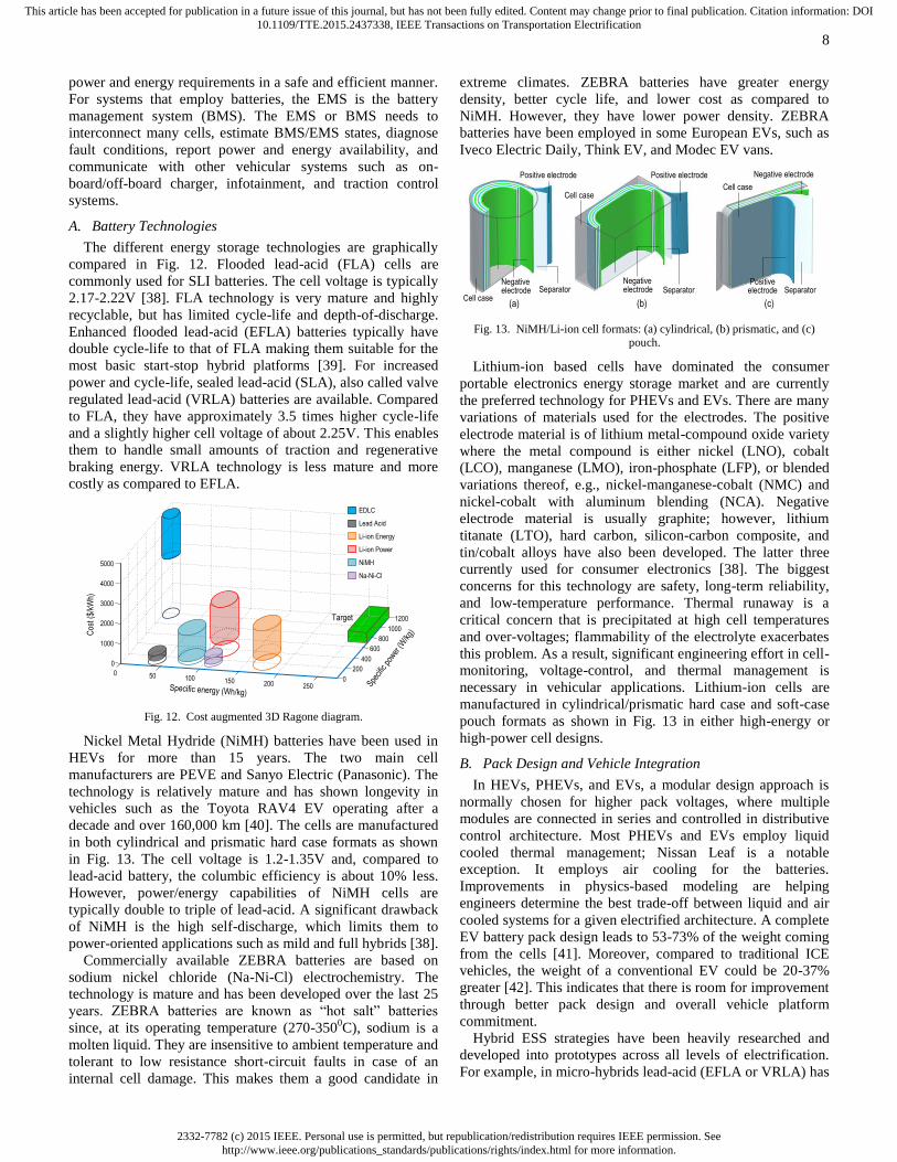
in both cylindrical and prismatic hard case formats as shown
in Fig. 13. The cell voltage is 1.2-1.35V and, compared to
lead-acid battery, the columbic efficiency is about 10% less.
However, power/energy capabilities of NiMH cells are
typically double to triple of lead-acid. A significant drawback
of NiMH is the high self-discharge, which limits them to
power-oriented applications such as mild and full hybrids [38].
Commercially available ZEBRA batteries are based on
sodium nickel chloride (Na-Ni-Cl) electrochemistry. The
technology is mature and has been developed over the last 25
years. ZEBRA batteries are known as “hot salt” batteries
since, at its operating temperature (270-3500C), sodium is a
molten liquid. They are insensitive to ambient temperature and
tolerant to low resistance short-circuit faults in case of an
internal cell damage. This makes them a good candidate in
extreme climates. ZEBRA batteries have greater energy
density, better cycle life, and lower cost as compared to
NiMH. However, they have lower power density. ZEBRA
batteries have been employed in some European EVs, such as
Iveco Electric Daily, Think EV, and Modec EV vans.
Negative electrode
Positive electrode
Separator
Positive electrode
Positive electrode Separator
(a) (b) (c)
Negative electrode
Negative electrode Separator
Cell case
Cell caseCell case
Fig. 13. NiMH/Li-ion cell formats: (a) cylindrical, (b) prismatic, and (c)
pouch.
Lithium-ion based cells have dominated the consumer
portable electronics energy storage market and are currently
the preferred technology for PHEVs and EVs. There are many
variations of materials used for the electrodes. The positive
electrode material is of lithium metal-compound oxide variety
where the metal compound is either nickel (LNO), cobalt
(LCO), manganese (LMO), iron-phosphate (LFP), or blended
variations thereof, e.g., nickel-manganese-cobalt (NMC) and
nickel-cobalt with aluminum blending (NCA). Negative
electrode material is usually graphite; however, lithium
titanate (LTO), hard carbon, silicon-carbon composite, and
tin/cobalt alloys have also been developed. The latter three
currently used for consumer electronics [38]. The biggest
concerns for this technology are safety, long-term reliability,
and low-temperature performance. Thermal runaway is a
critical concern that is precipitated at high cell temperatures
and over-voltages; flammability of the electrolyte exacerbates
this problem. As a result, significant engineering effort in cell-
monitoring, voltage-control, and thermal management is
necessary in vehicular applications. Lithium-ion cells are
manufactured in cylindrical/prismatic hard case and soft-case
pouch formats as shown in Fig. 13 in either high-energy or
high-power cell designs.
B. Pack Design and Vehicle Integration
In HEVs, PHEVs, and EVs, a modular design approach is
normally chosen for higher pack voltages, where multiple
modules are connected in series and controlled in distributive
control architecture. Most PHEVs and EVs employ liquid
cooled thermal management; Nissan Leaf is a notable
exception. It employs air cooling for the batteries.
Improvements in physics-based modeling are helping
engineers determine the best trade-off between liquid and air
cooled systems for a given electrified architecture. A complete
EV battery pack design leads to 53-73% of the weight coming
from the cells [41]. Moreover, compared to traditional ICE
vehicles, the weight of a conventional EV could be 20-37%
greater [42]. This indicates that there is room for improvement
through better pack design and overall vehicle platform
commitment.
Hybrid ESS strategies have been heavily researched and
developed into prototypes across all levels of electrification.
For example, in micro-hybrids lead-acid (EFLA or VRLA) has

2332-7782 (c) 2015 IEEE. Personal use is permitted, but republication/redistribution requires IEEE permission. Seehttp://www.ieee.org/publications_standards/publications/rights/index.html for more information.
This article has been accepted for publication in a future issue of this journal, but has not been fully edited. Content may change prior to final publication. Citation information: DOI10.1109/TTE.2015.2437338, IEEE Transactions on Transportation Electrification
9
been combined either with NiMH, lithium-ion, or
ultracapacitors [41]. Lead-acid and ZEBRA batteries have
been augmented with ultracapacitors to improve the
performance and battery life in electric vehicles [43]-[44]. The
most common ultracapacitors for transportation applications
are the electric double layer capacitor (EDLC) type. A variety
of topologies and integration strategies have been researched
for hybrid ESS in transportation electrification [45].
C. Future Trends and Technologies
An alternative electrochemistry seeking to replace lead-acid
is nickel-zinc batteries being commercialized by PowerGenix.
Advantages such as twice the service life, 65% weight
reduction, and recyclability higher than NiMH and Li-ion, but
comparable to lead acid, are claimed for this technology. This
makes them suitable for micro/mild hybrids [46].
Advanced Li-ion chemistries are under development to
increase cell voltage, and subsequently power and energy
capability. Two examples are improved NMC cathode
operating at 4.3V versus 4.15V [41] and lithium vanadium
phosphate (LVP) enabling cell voltages of 4.7-4.8V. The latter
has been demonstrated in a Subaru 64e prototype [47].
Hybrid capacitors have recently been commercially
developed as novel cells that combine elements of
electrochemical and electrostatic storage to integrate
advantages from both. Two examples are UltraBattery [48]
meant to replace lead-acid batteries and the lithium-ion
capacitor by JSR Micro.
With the recent and forecasted developments in vehicle ESS
technologies, the U.S. Advanced Battery Consortium
(USABC) has recently set more aggressive EV targets, such as
system level power density of 1000 W/L and energy density of
500 Wh/L [42]. Related research has suggested a 240+ km
range EV would be mass-marketable. Moreover, battery costs
per unit mile range are forecasted to drop by 50% by 2020.
Revolutionary energy storage technologies are being
researched and developed that aim to have anywhere from 2-
15 times more energy/power capability than today’s lithium
ion cells. These include lithium sulfur batteries being
developed by Oxis Energy, Zinc-air batteries pursued by ZAF
Energy Systems, and lithium-air batteries [49]. So-called flow
batteries based on vanadium or zinc-bromine electrochemistry
are also in development by American Vanadium and ZBB
Energy Corp.
VII. CONTROL AND SOFTWARE
Modern vehicles contain significant amount of software;
this is especially true for electrified vehicles. The size of
software in some modern vehicles reaches 100 million lines of
code [50] running on more than 100 electronic control units
(ECUs) [51]. Embedded software has been increasingly taking
over roles that traditionally belonged to mechanical, hydraulic,
pneumatic, and electrical components and is being used to
implement new advanced features. It is estimated that 90% of
innovations in vehicle technologies are due to electronic
components and software. Software increasingly performs
generic vehicle functions such as arbitrating gear selection in
shift-by-wire and other X-by-wire functionality to reduce
vehicle cost and weight. In addition to advanced safety
features such as anti-lock braking, collision avoidance, etc.,
embedded software implements electrified powertrain staples,
such as real-time optimal control of power flow to maximize
fuel economy and drivability, motor control, optimization of
battery performance and its protection, and engine start-stop.
A. System Controls in Electrified Powertrains
Electrified powertrains require multi-level control systems.
A top-level powertrain control unit measures or estimates the
vehicle states, e.g., applied torque on the wheels and inputs,
such as throttle actuation. This controller generates commands
for the lower-level subsystem control units that are the ICE,
battery pack, electric drive systems, power electronics, etc.
The typical goals of the powertrain control are to maximize
the fuel economy, minimize the emissions, and satisfy the
requested driving performance. These goals can be achieved
with rule-based or optimization-based control strategies [52]-
[53]. Electrified powertrains can require sophisticated control
systems to achieve the best performance. An example is the
combined mechanical and regenerative electrical braking
system that is typically implemented in electrified powertrains
for safety and efficiency. Mechanical braking is used when
regenerative braking is not sufficient due to the limited electric
machine torque and battery current.
Electric motor drives play a key role in electrified
powertrains. The main goal of a motor drive control unit is the
accurate actuation of a torque with high bandwidth, e.g., using
advanced control strategies [54]. Fast dynamic responses
enable better performance in engine speed control, smoother
engine start/stop function, and driveline damping controls. The
hill-hold performance and high-speed drive quality in an HEV
and EV are highly related to the torque control performance of
the motor in near-zero speed and near-maximum speed,
respectively [4]. The control unit is also responsible for
maximizing the electric drive system efficiency by choosing
the optimal operating point of the electric machine at low and
high speed [55] and it can optimize the operation of the
inverter [56]. Additionally, observers and estimators are
increasingly used to replace sensors. In particular, “sensorless”
algorithms are used to replace resolvers and encoders to
increase reliability and reduce cost. Similarly, temperature
estimation algorithms are available, e.g., for semiconductor
junction [57] and permanent magnet on the rotor [58].
The battery pack has another critical role in electrified
powertrains. In the pack, a significant amount of energy is
stored that is potentially harmful if released quickly. Thus,
battery packs use an energy management system for
protection, control, and estimation. The cells of a pack need to
be protected from operation in too low and too high
temperatures (fast ageing and damage), excessive current
(damage), depletion (recoverable dependent on the chemistry),
and overcharging (stress due to high voltage). The risk of
under and overvoltage is minimized by keeping each cell
state-of-charge (SOC) in balance. Balancing maximizes the
effective capacity of a battery stack. It is typically achieved
with dissipative hardware that transforms excess SOC into
heat. Non-dissipative topologies are based on dc-dc converters
and they move charge from cells with high SOC to cells with
low SOC. This reduces the energy losses significantly [59].
The SOC of a cell is not, in general, directly measurable, so

2332-7782 (c) 2015 IEEE. Personal use is permitted, but republication/redistribution requires IEEE permission. Seehttp://www.ieee.org/publications_standards/publications/rights/index.html for more information.
This article has been accepted for publication in a future issue of this journal, but has not been fully edited. Content may change prior to final publication. Citation information: DOI10.1109/TTE.2015.2437338, IEEE Transactions on Transportation Electrification
10
the BMS actuates balancing currents based on an SOC
estimate. One approach to obtain SOC is to estimate the so-
called open-circuit voltage and then map it through a nonlinear
look-up table. A monotonic nonlinear relationship has been
empirically observed between the open-circuit-voltage and
SOC. However, some cell chemistries, e.g., Lithium iron
phosphate, have flat open circuit voltage profiles and, hence,
SOC can be estimated only with large uncertainties using this
technique. For these chemistries, coulomb counting is often
preferred. It is a method that estimates SOC by integrating the
current and dividing by the cell capacity. This method is
susceptible to small measurement offsets that shift the
estimate over time. More sophisticated methods overcome
these shortcomings using battery modes and advanced
estimation techniques, e.g., Kalman filters [60] or neural
networks [61].
B. Software Requirements
Most software-related accidents occur when software still
behaves as specified by its requirements; however, the
requirements are flawed [62]. This occurs because of the
complexity of modern systems contained mostly in
interactions between different software components, hardware
components, humans, and the physical environment. Almost
all the software-related accidents in aerospace are due to
flawed software requirements. The aerospace industry has
virtually eliminated implementation errors (software not
behaving according to its requirements specification) through
the use of rigorous development processes based on DO-178B
and now DO-178C [63]. A key concept of software developed
to comply with DO-178B/C is that, for the most critical
software, 100% MC/DC (Modified Condition/Decision
Coverage) testing of the code must be achieved through test
cases derived from the (low level) requirements. This
obligation forces developers to create precise, unambiguous
requirements specifications and have traceability from
requirements to code that results in extensive test suites. But,
this high level of rigorous quality comes at substantial cost.
For the automotive industry to follow in the steps of the
aerospace industry, it must find tools and techniques that
reduce the current level of human effort required by the
aerospace industry to achieve the same level of quality as DO-
178C compliance.
C. Model Based Development (MBD)
MBD has proved to be an effective development paradigm
for automotive software. The implementation (coding) phase
of software development has been streamlined by automatic
code generation. Furthermore, MBD enabled moving the focus
of the development from code to models, enabling early
Verification & Validation (V&V) activities, thus significantly
decreasing the development costs as errors are found early in
the development process [64]. A number of methods and tools
have been used in the automotive MBD process contributing
to the steady decrease in the number of design and
implementation errors. For example, there are tools that can
automatically generate tests from models and enable
verification of designs (Simulink models) against their
requirements. MBD also leverages the capabilities of static
analysis tools at both the model and code level (e.g., Reactis
by Reactive Systems and Simulink Design Verifier (SDV) by
MathWorks at the model level and Polyspace by MathWorks
at the code level). Static analysis can discover run-time errors
like division by zero, overflow, out-of-bound array index, etc.
In general, proper tool support is essential in making a
software development process successful. The automotive
industry has successfully embedded into its development
process a set of tools highly integrated throughout the entire
software life cycle: tools for requirements management,
system design and models management, documentation
production, configuration management, traceability across the
software development lifecycle, and change management
(e.g., Rational Suite by IBM).
Recently, system modeling tools such as MapleSim,
AMESim, and Dymola have been successfully used in
automotive model-based systems engineering. They provide
intuitive plant modeling from engineering artifacts (e.g., from
schematics of powertrain architectures or sets of differential
equations). Although these tools are not geared specifically to
controller design, they serve as excellent environments for
real-time simulations with hardware-in-the-loop (HIL)
capabilities, system analysis (parameter optimization),
sensitivity analysis, etc. Ultimately, when compared to
traditional plant modeling, for example in Simulink, these
tools enable much quicker, less error-prone development [65]-
[66]. While these tools are yet to become a consistent part of a
typical automotive MBD process, given their benefits, their
use is likely to proliferate. For example, MapleSim has been
used to generate relevant calibrations from physical models of
different powertrains, effectively implementing variability in
software due to different powertrain architectures [67].
D. AUTOSAR (AUTomotive Open System ARchitecture)
The rapid increase in the complexity of software in modern
cars had prompted a need for a standardized software
architecture. The AUTOSAR initiative [68] resulted in
development of a standardized architecture with the main goal
of reusability of software and hardware components between
OEMs, suppliers, and different vehicle platforms. AUTOSAR
is a layered architecture that hides the details of particular
microcontroller in an ECU, and standardizes interfaces
between software components. Therefore, the architecture
provides a standardized platform to combine different
vehicular features, providing modularity and reusability.
E. Safety
The automotive industry has always considered safety as a
major engineering concern. The advent of the new
international automotive standard, ISO 26262: Road Vehicles
– Functional Safety [69], ratified in 2011, has recognized the
need to properly address safety of electrical and/or electronic
components, recognizing the rapidly increasing role of these
components in performing safety critical functions in cars.
ISO 26262 has become de facto standard in the automotive
industry. Although the standard suffers from issues common
to software engineering standards throughout different
domains (e.g., ambiguity, inconsistency, and focus on process
as opposed to focus on product), it represents an important
step to providing proper guidelines for the development of
safe vehicular software.

2332-7782 (c) 2015 IEEE. Personal use is permitted, but republication/redistribution requires IEEE permission. Seehttp://www.ieee.org/publications_standards/publications/rights/index.html for more information.
This article has been accepted for publication in a future issue of this journal, but has not been fully edited. Content may change prior to final publication. Citation information: DOI10.1109/TTE.2015.2437338, IEEE Transactions on Transportation Electrification
11
A key component of safety engineering is hazard analysis.
Hazard analysis identifies hazards and all the scenarios that
can lead to the hazards, so they can be eliminated or mitigated
against. For example, typical hazards in the automotive
industry are unintended deceleration/acceleration, loss of
braking, wrong direction, etc. The rapidly increasing role of
software in electrified vehicles has also made some of the
traditional hazard analysis techniques devised half a century
ago insufficient to properly tackle all the aspects of today’s
large software-intensive vehicular systems rich with complex
interactions with the environment and human operators. While
new hybrid powertrain architectures provide unprecedented
opportunities for improved energy efficiency, they also
introduce multiple potential sources of hazards. The
automotive industry is currently exploring new techniques that
would more appropriately account for the complexity in these
modern cars (e.g., systems-theoretic process analysis (STPA)
[70]).
VIII. CONCLUSIONS
Transportation electrification is a paradigm shift from less-
efficient internal combustion engine based vehicles towards
more-efficient and cleaner electrified vehicles to enable a
sustainable transportation system. Electrification can occur in
both vehicular propulsion and non-propulsion loads. Higher
degrees of electrification represent a larger-power electrical
path leading to less use of fossil fuels and, hence, better fuel
economy and lower greenhouse gas emissions. The level of
electrification starts from conventional vehicles where more
non-propulsion loads are electrified. Mild hybrids, full
hybrids, plug-in hybrids, and electric vehicles have a gradual
increase in the electrification level, where the fuel
consumption decreases and electric range increases.
In electrified powertrain applications, the efficiency of the
electric path and the power and energy density of the
components play critical roles. In addition, the selection of the
powertrain architecture, design of the powertrain components,
systems, controls, and software are coupled together to
improve the performance and reliability of the vehicle. In this
paper, the transportation electrification vision has been
explained and the major components of electrified powertrains
have been discussed, including power electronics, electric
machines, electrified powertrains, energy storage systems, and
controls and software. The applications, enabling
technologies, solutions, and future trends are investigated.
ACKNOWLEDGMENT
This research was undertaken, in part, thanks to funding
from the Canada Excellence Research Chairs Program.
REFERENCES
[1] United States Environment Protection Agency, Sources of Greenhouse
Gas Emissions, Transportation Sector Emissions, (April 25, 2013),
[Online]. Available: http://www.epa.gov/. [2] M. Slack, Our Dependence on Foreign Oil is Declining, The White
House Blog, March 2012, [Online]. Available:
http://www.whitehouse.gov/. [3] United States Environmental Protection Agency (EPA) Regulations and
Standards: Light-Duty, [Online]. Available: http://www.epa.gov/.
[Accessed: Jan. 12th, 2015].
[4] M. Zhang, P. Suntharalingam, Y. Yang, and W. Jiang, “Fundamentals of
Hybrid Electric Powertrains,” Advanced Electric Drive Vehicles, CRC Press, 2014.
[5] A. Emadi, “Transportation 2.0: Electrified-Enabling cleaner, greener,
and more affordable domestic electricity to replace petroleum,” IEEE Power and Energy Mag., vol. 9, no. 4, pp. 18-29, July/Aug. 2011.
[6] Bosch sees future requiring multiple powertrain technologies; the larger
the vehicle, the more the electrification (June 18, 2013), [Online]. Available: http://www.greencarcongress.com/.
[7] S. G. Wirasingha, M. Khan, and O. Gross, “48-V Electrification: Belt-
Driven Starter Generator Systems,” Advanced Electric Drive Vehicles, CRC Press, 2014.
[8] U.S. HEV Sales by Model, U.S. Department of Energy Alternative Fuels
Data Center (Updated April 2014), [Online]. Available: http://www.afdc.energy.gov/.
[9] U.S. PEV Sales by Model, U.S. Department of Energy Alternative Fuels
Data Center (Updated April 2014), [Online]. Available: http://www.afdc.energy.gov/.
[10] W. Jiang, Y. Yang, and P. Suntharalingam, “All-Electric Vehicles and
Range-Extended Electric Vehicles,” Advanced Electric Drive Vehicles, CRC press, 2014.
[11] United States Environment Protection Agency (EPA), Infographic:
Driving to 54.5 MPG by 2025, (August 28, 2012), [Online]. Available: http://www.epa.gov/.
[12] K. Asano, Y. Inaguma, H. Ohtani, E. Sato, M. Okamura, and S. Sasaki,
“High performance motor drive technologies for hybrid vehicles,” in Proc. IEEE Power Conversion Conference, Nagoya, Japan, Apr. 2007,
pp. 1584-1589. [13] T. A. Burress, S. L. Campbell, C. L. Coomer, C. W. Ayers, A. A.
Wereszczak, J. P. Cunningham, L. D. Marlino, L. E. Seiber, and H. T.
Lin, Evaluation of the 2010 Toyota Prius Hybrid Synergy Drive System, Oak Ridge National Lab, No. ORNL/TM-2010/253. 2011.
[14] H. A. Mantooth, M. D. Glover, and P. Shepherd, "Wide bandgap
technologies and their implications on miniaturizing power electronic systems," IEEE Journal of Emerging and Selected Topics in Power
Electronics, vol. 2, no. 3, pp. 374-385, Sept. 2014
[15] S. Jahdi, O. Alatise, C. Fisher, R. Li, and P. Mawby, "An evaluation of silicon carbide unipolar technologies for electric vehicle drive-trains,"
IEEE Journal of Emerging and Selected Topics in Power Electronics,
vol. 2, no.3, pp. 517-528, Sept. 2014 [16] Toyota and Denso develop SiC power semiconductor for power control
units; targeting 10% improvement in hybrid fuel efficiency (May 20
2014). [Online]. Available: http://www.greencarcongress.com/. [17] Toyota improve hybrid fuel efficiency by 10% with SiC inverter (May
21 2014). [Online]. Available: http://www.electric-vehiclenews.com/.
[18] H. Zhang, L. M. Tolbert, and B. Ozpineci, "Impact of SiC devices on hybrid electric and plug-in hybrid electric vehicles," IEEE Trans. on
Industry Applications, vol. 47, no. 2, pp. 912-921, Mar.-Apr. 2011.
[19] A. Bindra, “Wide-bandgap power devices are changing the power game,” IEEE Power Electronics Magazine, vol. 2, no. 1, pp. 4-6, Mar. 2015.
[20] Bruce Tuttle, Capacitor Technologies: A Comparison of Competing
options, October 2004, [Online]. Available: http://www1.eere.energy.gov/.
[21] Z. Liang and L. Li, “HybridPACK2 – advanced cooling concept and
package technologu for hybrid electric vehicles,” in Proc. IEEE Vehicle Power and Propulsion Conference, Harbin, China, Sept. 2008, pp. 1-5.
[22] P. Ning, Z. Liang, and F. Wang, “Power module and cooling system
thermal performance evaluation for HEV application,” IEEE Journal of Emerging and Selected Topics in Power Electronics, vol. 2, no. 3, pp.
487-495, Sept. 2014.
[23] Y. Wang, S. Jones, A. Dai, and G. Liu, “Reliability enchancement by integrated liquid cooling in power IGBT modules for hybrid and electric
vehicles,” in Proc. Microelectronics Reliability, vol. 54, no. 9-10, pp.
1911-1915, Sept.-Oct. 2014, ISSN: 0026-2714. [24] L. M. Tolbert, “Smart integarted power module,” presented at the 2012
U.S. DOE Hydrogen and Fuel Cells Program and Vehicle Technologies
Program Annual Merit Review and Peer Evaluation Meeting, Oak Ridge National Laboratory, May 2012.
[25] Y. Murakami, Y. Tajima, and S. Tanimoto, “Air-cooled full-SiC high
power density inverter unit,” in Proc. Electric Vehicle World Symposium and Exhibition, 2013, pp. 17-20.
[26] T. Nezu, Denso Reveals Details of 60 kW/L SiC Inverter, 2012.
[Online]. Available: http://techon.nikkeibp.co.jp/. [Accessed 9 Dec. 2014].

2332-7782 (c) 2015 IEEE. Personal use is permitted, but republication/redistribution requires IEEE permission. Seehttp://www.ieee.org/publications_standards/publications/rights/index.html for more information.
This article has been accepted for publication in a future issue of this journal, but has not been fully edited. Content may change prior to final publication. Citation information: DOI10.1109/TTE.2015.2437338, IEEE Transactions on Transportation Electrification
12
[27] S. Rogers, Electric Drive Status and Challenges, U.S. Department of
Energy Advanced Power Electronics and Electric Motors R&D Vehicle Technologies Program, July 2012, [Online]. Available:
http://www.energy.gov/.
[28] H. Shimizu, T. Okubo, I. Hirano, S. Ishikawa, and M. Abe, “Development of an integrated electrified powertrain for a newly
developed electric vehicle,” SAE International, 2013-01-1759, Aug.
2013. [29] K. M. Rahman, S. Jurkovic, S. Hawkins, S. Tarnowsky, and P.
Savagian, “Propulsion system design of a battery electric vehicle,” IEEE
Electrification Magazine, vol. 2, no. 2, pp. 14-24, June 2014. [30] B. Bilgin and A, Sathyan, “Fundamentas of Electric Machines,”
Advanced Electric Drive Vehicles, CRC Press, 2014.
[31] B. Bilgin and A. Emadi, “Electric motors in electrified transportation,” IEEE Power Electronics Magazine, vol. 1, no. 2, pp. 10-17, June 2014.
[32] M. Krishnamurthy, C. D. Edrington, A. Emadi, P. Asadi, M. Ehsani, and
B. Fahimi, “Making the case for applications of switched reluctance motor technology in automotive products,” IEEE Trans. on Power
Electronics, vol. 21, no. 3, pp. 659-675, May 2006.
[33] J. Ye, B. Bilgin, and A. Emadi, “An extended-speed low-ripple torque control of switched reluctance motor drives,” IEEE Trans. on Power
Electronics, vol. 30, no. 3, pp. 1457-1470, March 2015.
[34] P. C. Desai, M. Krishnamurthy, N. Schofield, and A. Emadi, “Novel switched reluctance machine configuration with higher number of rotor
poles than stator poles: concept to implementation,” IEEE Trans. on
Industrial Electronics, vol. 57, no. 2, pp. 649-659, Feb. 2010. [35] J. Oenick, “The challenges of developing electric traction drives for
heavy duty commercial vehicles,” presented at the 2012 IEEE Transportation Electrification Conference and Expo, Dearborn, MI,
June 2012.
[36] Y. Yang, K. Arshad-Ali, J. Roeleveld, and A. Emadi, “State-of-the-art electrified powertrains, hybrid, plug-in hybrid, and electric vehicles,”
International Journal of Powertrains, 2015.
[37] Y. Yang and A. Emadi, "Integrated electro-mechanical transmission systems in hybrid electric vehicles," in Proc. 2011 IEEE Vehicle Power
and Propulsion Conference (VPPC), Chicago, IL, Sept. 2011.
[38] P. P. Malysz, L. Gauchia, and H. H. Yang, “Fundamentals of electric energy storage systems,” Advanced Electric Drive Vehicles, CRC Press,
pp. 237-282, 2014.
[39] J. Albers, E. Meissner, and S. Shirazi, "Lead-acid batteries in micro-hybrid vehicles," Journal of Power Sources, vol. 196, no. 8, pp. 3993-
4002, 2011.
[40] T. J. Knipe, L. Gaillac, and J. Argueta, "100,000-mile evaluation of the Toyota RAV4 EV," Southern California Edison, Electric Vehicle
Technical Center, 2003, [Online]. Available:
http://www.evchargernews.com/. [41] M. Anderman, “Assessing the future of hybrid and electric vehicles: The
2014 xEV industry insider report,” Advanced Automotive Batteries,
2013. [42] J. Neubauer, A. Pesaran, C. Bae, R. Elder, and B. Cunningham,
"Updating United States Advanced Battery Consortium and Department
of Energy battery technology targets for battery electric vehicles," Journal of Power Sources, vol. 271, pp. 614-621, 2014.
[43] J. M. Blanes, R. Gutierrez, A. Garrigós, J. L. Lizan, and J. M. Cuadrado,
"Electric vehicle battery life extension using ultracapacitors and an FPGA controlled interleaved buck–boost converter." IEEE Trans. Power
Electronics, vol. 28, no. 12, pp. 5940-5948, 2013.
[44] J. Dixon, I. Nakashima, E. F. Arcos, and M. Ortuzar, "Electric vehicle using a combination of ultracapacitors and ZEBRA battery," IEEE
Trans. Industrial Electronics, vol. 57, no. 3, pp. 943-949, 2010.
[45] O. C. Onar and A. Khaligh, “Hybrid energy storage systems,” Advanced Electric Drive Vehicles, CRC Press, pp. 283-316, 2014.
[46] R. Brody, “Nickel Zinc (NiZn) batteries for transportation applications,”
PowerGenix, Accessed: Dec-15-2014. [Online]. Available: http://www.cleantechinvestor.com/.
[47] Lithium Vanadium Phosphate Battery, American Vanadium, 2014,
[Online]. Available: http://americanvanadium.com/. [48] A. Cooper, J. Furakawa, L. Lam, and M. Kellaway, “The ultrabattery –
A new battery design for a new beginning in hybrid elecric vehicle
energy storage,” Journal of Power Sources, vol. 188, no. 2, pp. 642-649, 2009.
[49] M. A. Reddy and M. Fichtner, "Batteries based on fluoride shuttle,"
Journal of Materials Chemistry, vol. 21, no. 43, pp. 17059-17062, 2011. [50] R. N. Charette, “This car runs on code,” (February 2009.) [Online]
Available:http://spectrum.ieee.org/. [Accessed: Dec 6th, 2014].
[51] EE Times Europe, “Innovation in the car: 90% comes from electronics
and software,” (April 29, 2014) [Online]. Available: http://www.automotive-eetimes.com/. [Accessed: Dec 6th, 2014].
[52] K. Ç. Bayindir, M. A. Gözüküçük, and A. Teke, “A comprehensive
overview of hybrid electric vehicle: Powertrain configurations, powertrain control techniques and electronic control units,” Energy
Conversion and Management vol. 52, no. 2, pp. 1305–1313, Feb. 2011.
[53] F. R. Salmasi, “Control strategies for hybrid electric vehicles: Evolution, classification, comparison, and future trends,” IEEE Trans. on Vehicular
Technology, vol. 56, no. 5, pp. 2393-2404, Sept. 2007.
[54] M. Preindl and S. Bolognani, “Model predictive direct torque control with finite control set for PMSM drive systems, Part 2: field weakening
operation,” IEEE Trans. on Industrial Informatics, vol. 9, pp. 648-657,
2013. [55] M. Preindl and S. Bolognani, “Optimal state reference computation with
constrained MTPA criterion for PM motor drives,” IEEE Trans. on
Power Electronics, 2014, early access. [56] M. Preindl, E. Scaltz, and P. Thogersen, “Switching frequency reduction
using model predictive direct current control for high power voltage
source inverters,” IEEE Trans. on Industrial Electronics, vol. 58, pp. 2826-2835, 2011.
[57] H. Chen, B. Ji, V. Pickert, and W. Cao, “Real-time temperature
estimation for power MOSFETs considering thermal aging effects,” IEEE Trans. on Device and Materials Reliability, vol. 14, pp. 220-228,
2014.
[58] B.-H. Lee, K.-S. Kim, J.-W. Jung, J.-P. Hong, and Y.-K. Kim, “Temperature estimation of IPMSM using thermal equivalent circuit,”
IEEE Trans. on Magnetics, vol. 48, pp. 2949-2952, 2012. [59] M. Preindl, C. Danielson, and F. Borrelli, “Performance evaluation of
battery balancing hardware,” European Control Conference, Zurih,
Switzerland, July 2013, pp. 4065-4070. [60] G. L. Plett, “Extended kalman filtering for battery management systems
of LiPB-based HEV battery packs part 1. Background,” Journal of
Power Sources, vol. 134, pp. 252-261, 2004. [61] M. Charkhgard and M. Farrokhi, “State-of-charge estimation for
lithium-ion batteries using neural networks and ekf,” IEEE Trans. on
Industrial Electronics, vol. 57, pp. 4178-4187, 2010. [62] N. G. Leveson, “Role of software in spacecraft accidents,” Journal of
Spacecraft and Rockets, vol. 41, no. 4, pp. 564-575, 2004.
[63] L. Rierson, Developing Safety-Critical Software: A Practical Guide for Aviation Software and DO-178C Compliance. CRC Press, 2013.
[64] M. Broy, S. Kirstan, H. Krcmar, B. Schätz, and J. Zimmermann, "What
is the benefit of a model-based design of embedded software systems in the car industry," Emerging Technologies for the Evolution and
Maintenance of Software Models, IGI Global, pp. 410-443, 2011.
[65] R. S. Razavian, N. L. Azad, and J. McPhee, “A battery hardware-in-the-loop setup for concurrent design and evaluation of real-time optimal
HEV power management controllers,” International Journal of Electric
and Hybrid Vehicles, vol. 5, no. 3, pp. 177-194, 2013. [66] D. Winkler and C. Gühmann, "Hardware-in-the-loop simulation of a
hybrid electric vehicle using Modelica/Dymola," in Proc. 22nd
International Battery, Hybrid and Fuel Cell Electric Vehicle Symposium (EVS-22), Yokohama, Japan, 2006.
[67] A. Korobkine, V. Pantelic, J. Carrette, and M. Lawford, “Automatic and
verifiable synthesis of implementations from mathematical models,” in Proc. International Symposium on Formal Methods, 2015, Submitted.
[68] AUTOSAR – AYTomotive Open System Architecture, [Online].
Available: http://www.autosar.org/. [69] N. G. Leveson, Engineering a Safer World: Systems Thinking Applied
to Safety (Engineering Systems), The MIT Press, 2012.
[70] P. Sundaram and M. Vernacchia, “Application of STPA to an automotive shift-by-wire system,” [Online]. Available:
http://psas.scripts.mit.edu/. [Accessed: Dec, 8th, 2014].

2332-7782 (c) 2015 IEEE. Personal use is permitted, but republication/redistribution requires IEEE permission. Seehttp://www.ieee.org/publications_standards/publications/rights/index.html for more information.
This article has been accepted for publication in a future issue of this journal, but has not been fully edited. Content may change prior to final publication. Citation information: DOI10.1109/TTE.2015.2437338, IEEE Transactions on Transportation Electrification
13
Berker Bilgin (IEEE S’09-M’12) is the Research Program Manager in Canada
Excellence Research Chair in Hybrid Powertrain
Program in McMaster Institute for Automotive Research and Technology (MacAUTO) at
McMaster University, Hamilton, Ontario,
Canada. He received his Ph.D. degree in Electrical Engineering from Illinois Institute of
Technology in Chicago, Illinois, USA. He is
managing many multidisciplinary projects on the design of electric machines, power electronics,
electric motor drives, and electrified powertrains.
Dr. Bilgin is the Program Chair of the 2015 IEEE Transportation Electrification Conference
and Expo (ITEC’15). He is the General Chair of ITEC’16.
Pierre Magne (IEEE S’11–M’13) received the
M.Sc. degree in electrical and electronics
engineering from the Institut National Polytechnique de Lorraine, Nancy, France, in
2009, and the M.Eng. degree in electrical
engineering from the Ecole Nationale Supérieure d’Electricité et de Mécanique, Nancy, in 2009,
and the Ph.D. degree in electrical engineering
from the University of Lorraine, Nancy, in 2012, respectively. During his Ph.D studies, he was
with the Groupe de Recherche en
Electrotechnique et Electronique de Nancy and the Safran Power Electronics Center, Nancy.
From 2012 to 2015, he was with the Canadian
Excellence Research Chair in Hybrid Powertrain program, McMaster Institute for Automotive Research and Technology, Hamilton, ON, Canada. Since
2015, he is with Schneider Electric in Burnaby, BC, Canada. His current
research interests include power systems design and control, power electronics converter design, nonlinear control, and their applications.
Pawel Malysz (IEEE S’06-M’12) received the B.Eng. degree in engineering physics, the
M.A.Sc. and Ph.D. degrees in electrical
engineering from McMaster University,
Hamilton, ON, Canada, in 2005, 2007 and 2011
respectively. In 2003-04 he was a biomedical
engineering intern at the Juravinski Cancer Centre, Hamilton, ON, Canada. From 2012-
2014 he was a Principal Research Engineer at
the McMaster Institute for Automotive Research and Technology, a Canada Excellence Research
Centre. He is an associate editor for IET Power
Electronics and currently is a Battery Management Systems Control Engineer at Fiat
Chrysler Automobiles in Michigan, USA. His research interests include energy systems, battery management software design, electrified
transportation, haptics, robotics, and advanced control engineering.
Yinye Yang (IEEE S’11-M14) received his B.E.
degree in Mechanical Engineering from the
Department of Precision Instruments and Mechanology at Tsinghua University, Beijing,
China, in 2010, and M.E. degree in Mechanical
Engineering from the University of Illinois at Urbana-Champaign (UIUC), Illinois, U.S., in
2010. He served as a research assistant of
Electric Engineering in Illinois Institute Technology (IIT), Illinois, U.S. from September
to December 2010, and then he received his
Ph.D. degree in Electrical Engineering from the Department of Electrical and Computer
Engineering of McMaster University, Ontario,
Canada in 2014. Presently, he is working as a principal research engineer for the Canada Excellence Research Chair in Hybrid Powertrain Program,
Hamilton, Ontario, Canada. Dr. Yang is the principal author/co-author of 4
patent applications, 5 book chapters, and numerous journal and conference papers. He serves as a reviewer and multiple session chairs for IEEE
Transportation Electrification Conference and Expo (ITEC). His current
research interests include hybrid electric vehicles, hybrid powertrain system and components, vehicle electrification and optimization, electric machine
designs and control, switched reluctance motor design and applications,
machine and powertrain testing, and interior permanent magnet machine design and optimization.
Vera Pantelic received her B.Eng. in Electrical Engineering from University of Belgrade,
Serbia, in 2001, and both her M.A.Sc, and Ph.D.
in Software Engineering from McMaster University, Hamilton, in 2005, and 2011,
respectively. Her main research interests include
development and certification of safety-critical software systems, model-based design, and
supervisory control of discrete event systems.
She is currently working as a Principal Research Engineer at the McMaster Centre for Software
Certification, and McMaster Institute for
Automotive Research and Technology (MacAUTO) at McMaster University.
Matthias Preindl is a Post Doctoral Research Associate at the McMaster Institute for
Automotive Research and Technology
(MacAUTO), McMaster University, Canada. He received the PhD degree in Energy Engineering
from the Doctoral School of Industrial Engineering at University of Padua, Italy (2014),
the MSc degree in Electrical Engineering and
Information Technology from ETH Zurich, Switzerland (2010), and the BSc degree in
Electrical Engineering (summa cum laude) form
University of Padua, Italy (2008). M. Preindl was a visiting scholar and visiting
student at University of California, Berkeley,
USA and Aalborg University, Denmark, respectively. Also, he was a trainee at the National Research Council (CNR), Italy. From 2010 to 2012, he was
with Leitwind AG, Italy, where he was a R&D engineer in Power Electronic
and Drives. He obtained several honours including merit scholarships, a price for outstanding achievements during his studies, and a best presentation
award. M. Preindl is involved in design and control of power electronic and
drive systems with primary focus on renewable-energy power plants and innovative transportation systems.
Alexandre Korobkine received his B.Eng. and M.A.Sc. in Software Engineering from
McMaster University, Hamilton, Canada in
2002 and 2005 respectively. He has worked as a simulation development engineer at
Maplesoft, Waterloo, Canada from 2011 until
2014. Currently, he is working as an Algorithm Design and Development Engineer at the
General Motors’ Milford Proving Grounds and
finishing his Ph.D studies at McMaster University. His main professional interests
include automotive control systems and
symbolic model-based design and development.
Weisheng (James) Jiang received his
Bachelor’s Degree in vehicle engineering from
College of Automotive Engineering, Jilin University, China in 2009. He worked as a
research assistant at the Clean Energy
Automotive Engineering Research Center, Tongji University, China from 2009 to 2011.
Currently, he is a Ph.D. student at the McMaster
Institute for Automotive Research and Technology (MacAUTO). His main research
interests include electric vehicle and hybrid
electric vehicle powertrain design, switched reluctance motor design and control.

2332-7782 (c) 2015 IEEE. Personal use is permitted, but republication/redistribution requires IEEE permission. Seehttp://www.ieee.org/publications_standards/publications/rights/index.html for more information.
This article has been accepted for publication in a future issue of this journal, but has not been fully edited. Content may change prior to final publication. Citation information: DOI10.1109/TTE.2015.2437338, IEEE Transactions on Transportation Electrification
14
Mark Lawford is a Professor in McMaster
University’s Department of Computing and
Software and the Associate Director of the McMaster Centre for Software Certification.
He has a B.Sc.('89) in Engineering Mathematics
from Queen's University, Kingston, where he received the University Medal in Engineering
Mathematics. His M.A.Sc.('92) and Ph.D. ('97)
are from the Systems Control Group in the Department of Electrical and Computer
Engineering at the University of Toronto. His
research interests include software certification, application of formal methods to safety critical
real-time systems, and supervisory control of
discrete event systems. He worked at Ontario Hydro as a real-time software verification consultant on the Darlington Nuclear Generating Station
Shutdown Systems Redesign project, receiving the Ontario Hydro New
Technology Award for Automation of Systematic Design Verification of Safety Critical Software in 1999. He joined McMaster University's
Department of Computing and Software in 1998 where he helped to develop
the Software Engineering programs and Mechatronics Engineering programs. He has been a guest co-editor of joint special issues on Software Inspection of
IEEE Software and IEEE Transactions on Software Engineering. He served
as the Section Chair for Computer Systems on the Computer Science Evaluation Group (EG-1507) for the 2010 NSERC Discovery Grant
Competition. In August 2010 he was a visiting researcher at the Center for Devices and Radiological Health, Office of Science and Engineering
Laboratories of the U.S. FDA. He is a licensed Professional Engineer in the
province of Ontario and a Senior Member of the IEEE.
Ali Emadi (IEEE S’98-M’00-SM’03-F’13)
received the B.S. and M.S. degrees in electrical engineering with highest distinction from Sharif
University of Technology, Tehran, Iran, in 1995
and 1997, respectively, and the Ph.D. degree in electrical engineering from Texas A&M
University, College Station, TX, in 2000. He is
the Canada Excellence Research Chair in Hybrid Powertrain and Director of McMaster Institute
for Automotive Research and Technology
(MacAUTO) at McMaster University in Hamilton, Ontario, Canada. Before joining
McMaster University, Dr. Emadi was the Harris
Perlstein Endowed Chair Professor of Engineering and Director of the Electric Power and Power Electronics Center
and Grainger Laboratories at Illinois Institute of Technology (IIT) in Chicago,
Illinois, USA. In addition, he was the Founder, Chairman, and President of Hybrid Electric Vehicle Technologies, Inc. (HEVT) – a university spin-off
company of IIT. Dr. Emadi is the recipient of numerous awards and
recognitions. He was the advisor for the Formula Hybrid Teams at IIT and McMaster University, which won the GM Best Engineered Hybrid Systems
Award at the 2010 and 2013 competitions, respectively. He is the principal
author/coauthor of over 350 journal and conference papers as well as several books including Vehicular Electric Power Systems (2003), Energy Efficient
Electric Motors (2004), Uninterruptible Power Supplies and Active Filters
(2004), Modern Electric, Hybrid Electric, and Fuel Cell Vehicles, Second Edition (2009), and Integrated Power Electronic Converters and Digital
Control (2009). He is also the editor of the Handbook of Automotive Power
Electronics and Motor Drives (2005) and Advanced Electric Drive Vehicles (2014). Dr. Emadi was the inaugural general chair of the 2012 IEEE
Transportation Electrification Conference and Expo (ITEC) and has chaired
several IEEE and SAE conferences in the areas of vehicle power and propulsion. He is the Editor-in-Chief of the IEEE Transactions on
Transportation Electrification.
Related Documents


