Making Ethernet Services a Profitable Reality

Welcome message from author
This document is posted to help you gain knowledge. Please leave a comment to let me know what you think about it! Share it to your friends and learn new things together.
Transcript
Making Ethernet Services a Profitable Reality
FUJITSU NETWORK COMMUNICATIONS INC.2801 Telecom Parkway, Richardson, Texas 75082-3515Telephone: (972) 690-6000(800) 777-FAST (U.S.)us.fujitsu.com/telecom
1
IntroductionThe competitive landscape for the residential and commercial communications market is well documented. Telecom companies with deep pockets, corporate commitments, and Wall Street expectations are making forays into video programming and will threaten core MSO residential business. MSOs are competing for residential customers by adding voice service and offering a bundle of voice, Internet access and video. In addition to competing for residential customers, MSOs must leverage their embedded fiber plant to deliver commercial services and gain incremental revenue on their existing infrastructure. At stake is the ~$60B per year small and medium business market that is traditionally underserved by telecom carriers. [1]
Simultaneously, there is a fundamental shift in the expectations and requirements of commercial enterprises about how their communications needs should be met. This shift, toward Ethernet, is a significant disruption in the marketplace and therefore an opportunity to gain customers and market share.
Traditionally, commercial enterprises purchase TDM services in the form of DS1 and DS3 access lines for voice, private line, and legacy data (Frame Relay and ATM) applications. These TDM access lines, while widely available, possess severe limitations. TDM access lines are rigid in terms of their available bandwidth offerings, QoS, ability to provide simple multi-point connectivity, and ability to support simple changes to service offerings. TDM access lines also require expensive CPE devices to translate and insert data from Ethernet-based corporate LAN protocols to the traditional TDM network. This CPE equipment is an additional cost burden to the enterprise and creates additional potential points of failure, while adding nothing to the richness of the service offering. To service providers, commodity DS1 and DS3 services require a truck roll to perform simple service modifications, leading to very long lead times for things like simple increases in bandwidth to an existing service.
Ethernet technology is well positioned to solve many of these service challenges. Enterprises everywhere are demanding native Ethernet services from the providing community because Ethernet, as a single, universal “jack” to the network, offers several significant advantages and overcomes the limitations associated with traditional services. Ethernet provides:
• an inexpensive and well understood handoff to the service provider• a way to eliminate unnecessary CPE devices• a flexible single interface that can simultaneously carry multiple distinct services with multiple
characteristics• an interface that allows easy increases in bandwidth or addition of services without forcing a service
provider site visit
In addition to providing advantages to the enterprise user, Ethernet solutions offer several advantages to the service provider in terms of operational savings and the ability to differentiate services from competitors. Ethernet also carries the promise of being uniquely able to support a wide variety of services from best effort, low bandwidth, latency insensitive, multipoint services to guaranteed bandwidth, latency sensitive, point-to-point services—all from a single infrastructure investment.
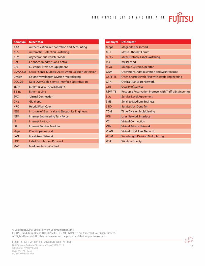
For your convenience, a list of acronyms can be found at the end of this document.
FUJITSU NETWORK COMMUNICATIONS INC.2801 Telecom Parkway, Richardson, Texas 75082-3515Telephone: (972) 690-6000(800) 777-FAST (U.S.)us.fujitsu.com/telecom
2
Service providers have not been sitting still and have been offering Ethernet services in response to enterprise demands and anticipated competitive threats during the telecom bubble in the late 1990s. Older Ethernet services are not based on the latest technology advances and so may not live up to current enterprise network expectations.
In particular, the issues of Ethernet connection performance and ubiquitous network coverage are key limitations with existing Ethernet services offerings today and therefore represent an important opportunity for MSOs to differentiate and successfully compete.
The Appeal of EthernetEthernet technology offers some significant benefits both to end users and to service providers. To the end user, Ethernet is the most well-understood enterprise interface, which makes it inexpensive to troubleshoot and provision. An Ethernet handoff to the service provider often implies lower interface costs on CPE or the complete removal of specialized CPE. Ethernet offers the potential of providing to end users inexpensive multipoint services due to its inherent broadcast capabilities.
Ethernet benefits end users and services providers alike by offering the ability to provision multiple services such as Layer 2 VPN, point-to-point private line, voice, Internet access, video and Layer 3 VPN, from a single port. With previous technologies, there were often specialized interfaces for data, video and voice. By providing multiple services over a single port, the service provider can improve the time to deliver new services and sell the end user additional services without having to incur the operational expense of rolling a truck to deploy a new interface. Similarly, bandwidth increases are also possible without adding additional interfaces or changing interface types.
These attractive benefits of Ethernet make it the emerging dominant currency for communications services, including support for everything from residential voice and video to commercial services. The MEF plays a key role in defining industry terminology and an architectural framework for the uniform delivery of Ethernet-based service offerings.
Ethernet Services TerminologyThe MEF has defined a generic structure for describing Ethernet connectivity and Ethernet access services. This generic structure defines both E-Line (point-to-point) and E-LAN (point-to-multipoint or multipoint-to-multipoint) services as logical associations (i.e., EVCs) among Ethernet UNIs [2].
The MEF further defines a series of service attributes that can apply to E-Line and E-LAN services [3]. The MEF defines attributes for both individual EVCs and for the UNI interface itself. EVC attributes include connection performance attributes such as Ethernet frame loss, delay (and delay variation), frame delivery attributes (i.e., specifications for what types of frames are transported across the network), customer VLAN tag handling attributes, and Layer 2 control protocol attributes. In particular, the connection performance attributes are important to service providers in differentiating their services.
FUJITSU NETWORK COMMUNICATIONS INC.2801 Telecom Parkway, Richardson, Texas 75082-3515Telephone: (972) 690-6000(800) 777-FAST (U.S.)us.fujitsu.com/telecom
3
These service types and service attributes are defined as part of an overall architectural framework that includes underlying transport layers and optional application services layers [4]. This architecture approach leaves room for both equipment vendors and service providers to innovate.
Equipment vendors are free to develop networking gear that provides innovative services using a variety of optional supporting transport technologies. These technologies include:
• SONET/SDH• Ethernet• IEEE 802.11 Wi-Fi• WDM or OTN transport technologies• Connection transport technologies such as VLAN multiplexing or MPLS along with associated control
plane protocols [5],[6]
The transport layer and connection transport technologies can be extremely important in determining the actual service experience of the end user, how the service provider differentiates the service offering, and the kind of SLAs the service provider is capable of offering.
Service providers are similarly free to develop and define offerings to their end customers, as well as create services that are based on MEF attributes and attributes that are not specified by the MEF. Examples of these attributes include mileage, protection switching time, and the degree to which network resources are dedicated to the customer or shared by multiple customers.
Additionally, service providers have historically positioned transport-oriented services differently from switched services, and Ethernet fits in both models. Transport services typically involve a lower degree of sharing of network resources and therefore contain mileage pricing components (known as rate elements). Switched services typically involve a higher degree of network resource sharing and often contain no mileage or limited mileage rate elements.
Of great importance, service providers are free to innovate regarding the SLAs they offer to their customers. These SLAs include attributes such as service availability, and can also include agreements on performance attributes. As described above, these performance-related SLAs can often depend upon the type of optional connection transport technology that is deployed.
Ethernet creates a market disruption opportunity for new service providers to gain commercial services market share. As service providers are working vigorously to add Ethernet services to their commercial services portfolios, there is opportunity for MSOs to innovate and provide services that incumbent providers do not offer.
FUJITSU NETWORK COMMUNICATIONS INC.2801 Telecom Parkway, Richardson, Texas 75082-3515Telephone: (972) 690-6000(800) 777-FAST (U.S.)us.fujitsu.com/telecom
4
State of Switched Ethernet ServicesSwitched Ethernet services are particularly well suited for mid-tier and smaller commercial service customers. Typically, a switched service offering is priced lower than a transport offering because it uses a common infrastructure that is shared across multiple customers and mileage charges are relatively low. In addition, switched services are an excellent match for connectivity requirements that involve multiple sites, such as connectivity among two business locations and an ISP.
The connection performance attributes of frame loss, frame delay and delay variation are an important area for services differentiation as MSOs compete with providers that have an embedded services infrastructure. Although service providers have been offering some type of Ethernet services for some time, older Ethernet infrastructures create a key disadvantage because most embedded services do not allow the service provider to offer robust service level agreements regarding connection performance attributes.
Often, connection performance attributes are not included in SLAs at all or SLAs describe connection performance that is averaged across a set of connections and over a set of periodic measurement intervals. To obtain average SLAs, the customer is often forced to use a second port to purchase best effort services. Needing additional ports counteracts the promise of Ethernet in providing all services on a single port. In no case does a major tariffed Ethernet offering currently include an actual guarantee of per-connection frame loss, delay or delay variation. This is a direct reflection of the connection transport technology approaches that the underlying networks provide.
According to numerous industry surveys, these connection performance SLA concerns are critical to commercial users and are explicitly mentioned as influencing their selection of a service provider. [7], [8]
Furthermore, these surveys indicate that service availability and network coverage is a key requirement. Traditional TDM services continue to have a strong foothold in the marketplace simply because they are widely available. Service provides must address network coverage issues to realize the promise of Ethernet.
Solving Connection Performance and Network Coverage IssuesEthernet creates a market disruption opportunity for new service providers to gain commercial services market share. As service providers are working vigorously to add Ethernet services to their commercial services portfolios, there is opportunity for MSOs to innovate and provide services that incumbent providers do not offer, and to make those offerings available to end users that other providers are not reaching.
FUJITSU NETWORK COMMUNICATIONS INC.2801 Telecom Parkway, Richardson, Texas 75082-3515Telephone: (972) 690-6000(800) 777-FAST (U.S.)us.fujitsu.com/telecom
5
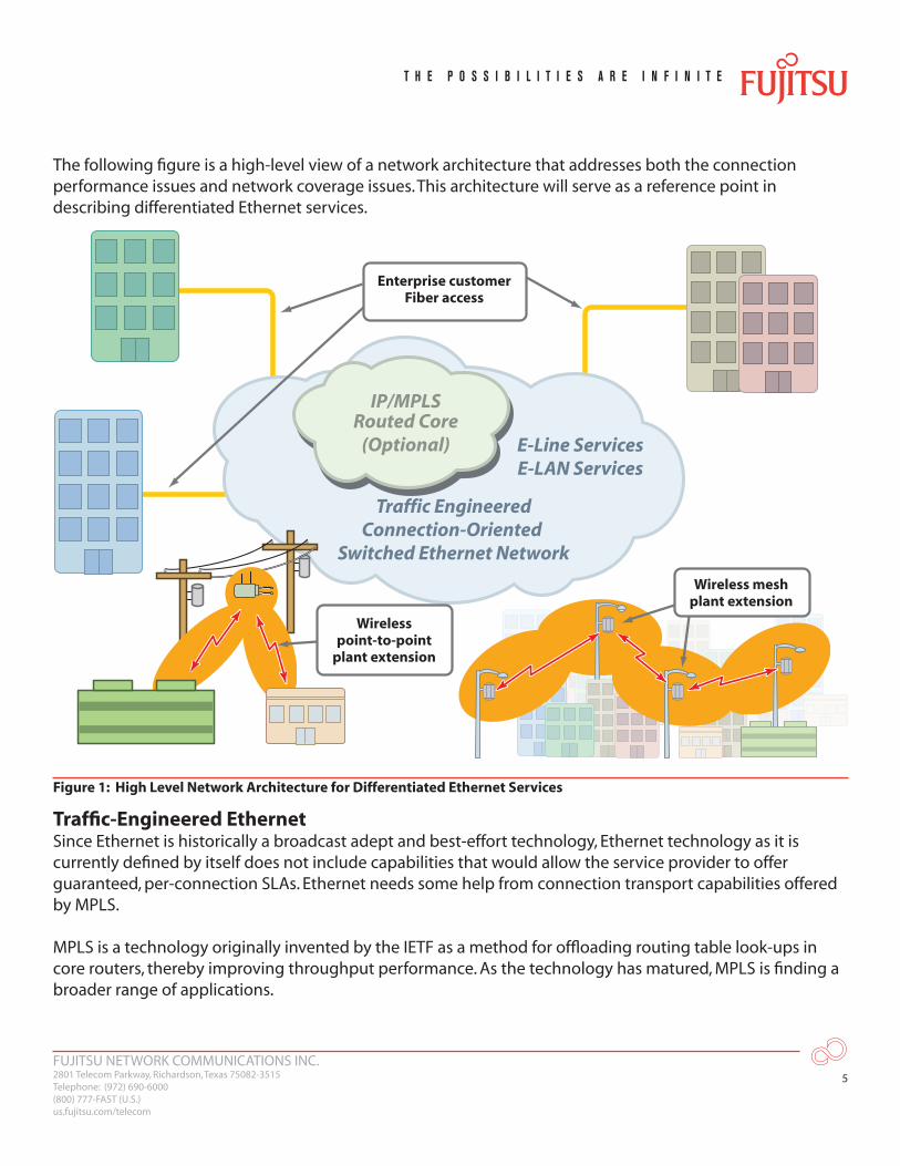
The following figure is a high-level view of a network architecture that addresses both the connection performance issues and network coverage issues. This architecture will serve as a reference point in describing differentiated Ethernet services.
Traffic EngineeredConnection-Oriented
Switched Ethernet Network
IP/MPLSRouted Core
(Optional) E-Line ServicesE-LAN Services
Enterprise customerFiber access
Wireless meshplant extension
Wirelesspoint-to-point
plant extension
Figure 1: High Level Network Architecture for Differentiated Ethernet Services
Traffic-Engineered EthernetSince Ethernet is historically a broadcast adept and best-effort technology, Ethernet technology as it is currently defined by itself does not include capabilities that would allow the service provider to offer guaranteed, per-connection SLAs. Ethernet needs some help from connection transport capabilities offered by MPLS.
MPLS is a technology originally invented by the IETF as a method for offloading routing table look-ups in core routers, thereby improving throughput performance. As the technology has matured, MPLS is finding a broader range of applications.
FUJITSU NETWORK COMMUNICATIONS INC.2801 Telecom Parkway, Richardson, Texas 75082-3515Telephone: (972) 690-6000(800) 777-FAST (U.S.)us.fujitsu.com/telecom
6
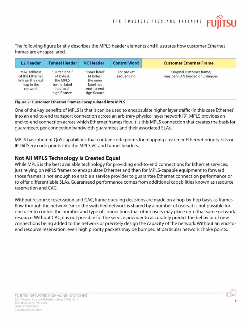
The following figure briefly describes the MPLS header elements and illustrates how customer Ethernet frames are encapsulated.
L2 Header
MAC addressof the Ethernetlink on the next
hop in thenetwork
“Outer label”(4 bytes);the MPLS
tunnel labelhas local
significance
“Inner label”(4 bytes);the innerlabel has
end-to-endsignificance
For packetsequencing
Original customer frame;may be VLAN tagged or untagged
Tunnel Header VC Header Control Word Customer Ethernet Frame
Figure 2: Customer Ethernet Frames Encapsulated into MPLS
One of the key benefits of MPLS is that it can be used to encapsulate higher layer traffic (in this case Ethernet) into an end-to-end transport connection across an arbitrary physical layer network [9]. MPLS provides an end-to-end connection across which Ethernet frames flow. It is this MPLS connection that creates the basis for guaranteed, per-connection bandwidth guarantees and their associated SLAs.
MPLS has inherent QoS capabilities that contain code points for mapping customer Ethernet priority bits or IP DiffServ code points into the MPLS VC and tunnel headers.
Not All MPLS Technology is Created EqualWhile MPLS is the best available technology for providing end-to-end connections for Ethernet services, just relying on MPLS frames to encapsulate Ethernet and then for MPLS-capable equipment to forward those frames is not enough to enable a service provider to guarantee Ethernet connection performance or to offer differentiable SLAs. Guaranteed performance comes from additional capabilities known as resource reservation and CAC.
Without resource reservation and CAC, frame queuing decisions are made on a hop-by-hop basis as frames flow through the network. Since the switched network is shared by a number of users, it is not possible for one user to control the number and type of connections that other users may place onto that same network resource. Without CAC, it is not possible for the service provider to accurately predict the behavior of new connections being added to the network or precisely design the capacity of the network. Without an end-to-end resource reservation, even high priority packets may be bumped at particular network choke points.
FUJITSU NETWORK COMMUNICATIONS INC.2801 Telecom Parkway, Richardson, Texas 75082-3515Telephone: (972) 690-6000(800) 777-FAST (U.S.)us.fujitsu.com/telecom
7
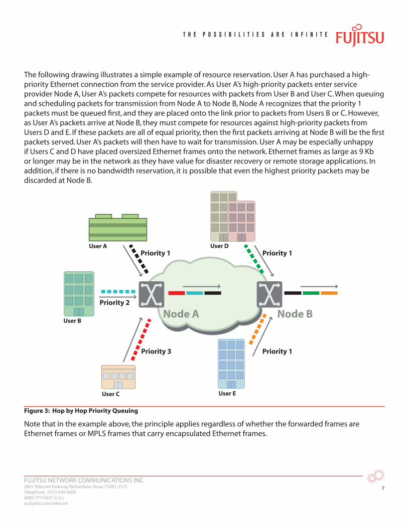
The following drawing illustrates a simple example of resource reservation. User A has purchased a high-priority Ethernet connection from the service provider. As User A’s high-priority packets enter service provider Node A, User A’s packets compete for resources with packets from User B and User C. When queuing and scheduling packets for transmission from Node A to Node B, Node A recognizes that the priority 1 packets must be queued first, and they are placed onto the link prior to packets from Users B or C. However, as User A’s packets arrive at Node B, they must compete for resources against high-priority packets from Users D and E. If these packets are all of equal priority, then the first packets arriving at Node B will be the first packets served. User A’s packets will then have to wait for transmission. User A may be especially unhappy if Users C and D have placed oversized Ethernet frames onto the network. Ethernet frames as large as 9 Kb or longer may be in the network as they have value for disaster recovery or remote storage applications. In addition, if there is no bandwidth reservation, it is possible that even the highest priority packets may be discarded at Node B.
Node A Node B
User A
User B
Priority 2
Priority 1 Priority 1
Priority 1Priority 3
User C
User D
User E
Figure 3: Hop by Hop Priority Queuing
Note that in the example above, the principle applies regardless of whether the forwarded frames are Ethernet frames or MPLS frames that carry encapsulated Ethernet frames.
FUJITSU NETWORK COMMUNICATIONS INC.2801 Telecom Parkway, Richardson, Texas 75082-3515Telephone: (972) 690-6000(800) 777-FAST (U.S.)us.fujitsu.com/telecom
8
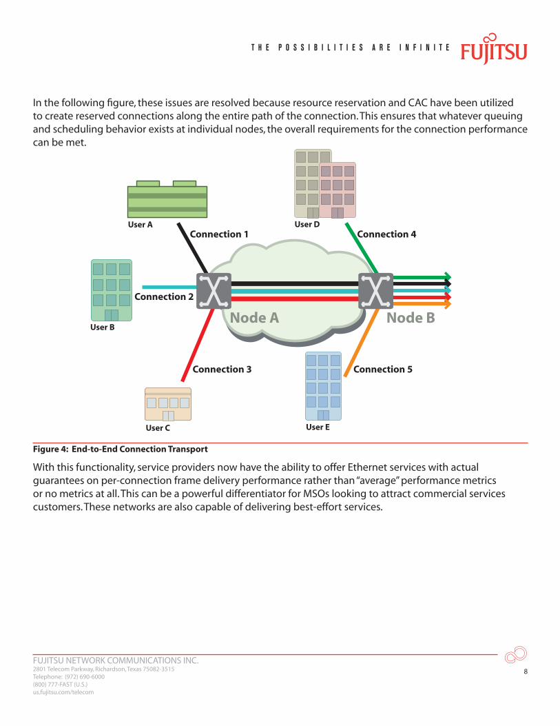
In the following figure, these issues are resolved because resource reservation and CAC have been utilized to create reserved connections along the entire path of the connection. This ensures that whatever queuing and scheduling behavior exists at individual nodes, the overall requirements for the connection performance can be met.
Node A Node B
User A
User B
Connection 2
Connection 1 Connection 4
Connection 5Connection 3
User C
User D
User E
Figure 4: End-to-End Connection Transport
With this functionality, service providers now have the ability to offer Ethernet services with actual guarantees on per-connection frame delivery performance rather than “average” performance metrics or no metrics at all. This can be a powerful differentiator for MSOs looking to attract commercial services customers. These networks are also capable of delivering best-effort services.
FUJITSU NETWORK COMMUNICATIONS INC.2801 Telecom Parkway, Richardson, Texas 75082-3515Telephone: (972) 690-6000(800) 777-FAST (U.S.)us.fujitsu.com/telecom
9
Key Enabling TechnologiesThere are certain technologies that allow all service providers to provide these capabilities. These include RSVP-TE [10] and OSPF-TE [11]. The OSPF-TE routing protocol discovers the network topology and can be used to communicate information about the resources available in each network element. When customers request new connections, these connections can be signaled through the network using RSVP-TE in conjunction with LDP to request the necessary resources along the route of the connection. The elements are able to check their own resources and then accept the request if those resources are available.
Without RSVP-TE functionality, the network elements can still agree on MPLS label information and define a connection, but that connection will have no bandwidth reservation and no way to guarantee the frame delivery performance of the connection.
The Advantage of MPLSWe’ve seen that by adding routing and signaling protocols with traffic engineering extensions and with the use of CAC algorithms, MPLS can be leveraged in standards-defined terms to provide guaranteed Ethernet connections that support guaranteed SLAs. The MPLS technology suite carries several unique additional advantages that are not available using alternative technologies such as provider VLAN encapsulations based on IEEE 802.1Q [12]. The MPLS frame format allows for the standardization of robust OAM operations [13,14], has a large 20-bit label field to support scalability (compared with a 12-bit field defined by IEEE 802.1Q), and can be used over an embedded IP/MPLS core network, thereby allowing Ethernet services across converged core packet networks.
MPLS further provides a guaranteed 50 ms APS capability (known as MPLS fast reroute) [15]. With MPLS fast reroute, protection bandwidth is dedicated to the working connections, thereby guaranteeing protection switching capabilities on par with traditional SONET APS technologies.
Ethernet On-ramp Approaches for MSOsInitial Ethernet penetration has been to areas that are served directly by fiber. However, only approximately 11% of commercial customers are fiber-fed [1]. This network coverage issue is exacerbated in MSO networks since the HFC plant often runs along one side of the street, highway or river while potential commercial users are on the other side. Industry estimates indicate that potentially 50% of SMBs cannot be served due to difficulties in scaling the last mile.
To fully offer differentiated Ethernet services, MSOs have to solve the network coverage issue in such a way that it is compatible with the differentiated Ethernet core network. One powerful answer to this problem is to leverage emerging wireless technologies, providing what is termed plant extension.
FUJITSU NETWORK COMMUNICATIONS INC.2801 Telecom Parkway, Richardson, Texas 75082-3515Telephone: (972) 690-6000(800) 777-FAST (U.S.)us.fujitsu.com/telecom
10
Point-to-Point Plant Extension and the Value of Standard InterfacesA common approach for providing wireless plant extension is to strand-mount a wireless device directly on the MSO HFC plant. This provides the well-understood advantage of not having to lease space on utility poles. There are a variety of interface and networking options both on the end-user facing side (client) and the network facing side (network) that can be available using this type of approach.
One approach for the client interface is to leverage standard IEEE 802.11x Wi-Fi protocols directly from the strand-mount unit. This has an advantage in that any user with a laptop or similar wireless device can attach to the network without having to rely on external CPE. Key applications for this would be MSO-provided services to entities like municipalities that may want to offer hot-spot services in a park or similar location that does not have indoor facilities. Hot spot services can also be offered to SMBs like coffee shops without requiring them to purchase CPE. This can also serve as a low-end Internet access solution for small businesses.
There are a variety of options of IEEE 802.11x. These options have different bandwidth capabilities. For example, IEEE 802.11b [16] is a half-duplex MAC approach operating in the 2.4 GHz spectrum that yields a theoretical bandwidth of 11 Mbps, but practically provides bidirectional throughput at around 5 Mbps. IEEE 802.11g [17] operates in the 2.4 GHz spectrum as well, but provides a half-duplex bandwidth of 54 Mbps and a practical bidirectional throughput of 20 Mbps. IEEE 802.11a operates in the 5 GHz spectrum with roughly the same bandwidth characteristics of IEEE 802.11g.
Wi-Fi employs the same MAC approach as Ethernet (CSMA/CD) and deployment design can include both broadcast coverage and directional coverage. This allows for either an increased collision domain to enable more customers and broader coverage, or a smaller collision domain serving fewer customers.
Security is provided in these types of solutions by the MSO assigning an IEEE 802.11 SSID to each hot spot provider and having the network separate traffic by assigning a VLAN to each SSID. User password and profiles can also be utilized through a standard AAA protocol.
Another approach for the client interface is to use customer located equipment. This allows for more scalable commercial services applications where the customer would deploy their own router as CPE and attach it to MSO-owned customer located equipment with an Ethernet connection. This type of solution has benefits in that bandwidth can be dedicated to a particular customer location.
FUJITSU NETWORK COMMUNICATIONS INC.2801 Telecom Parkway, Richardson, Texas 75082-3515Telephone: (972) 690-6000(800) 777-FAST (U.S.)us.fujitsu.com/telecom
11
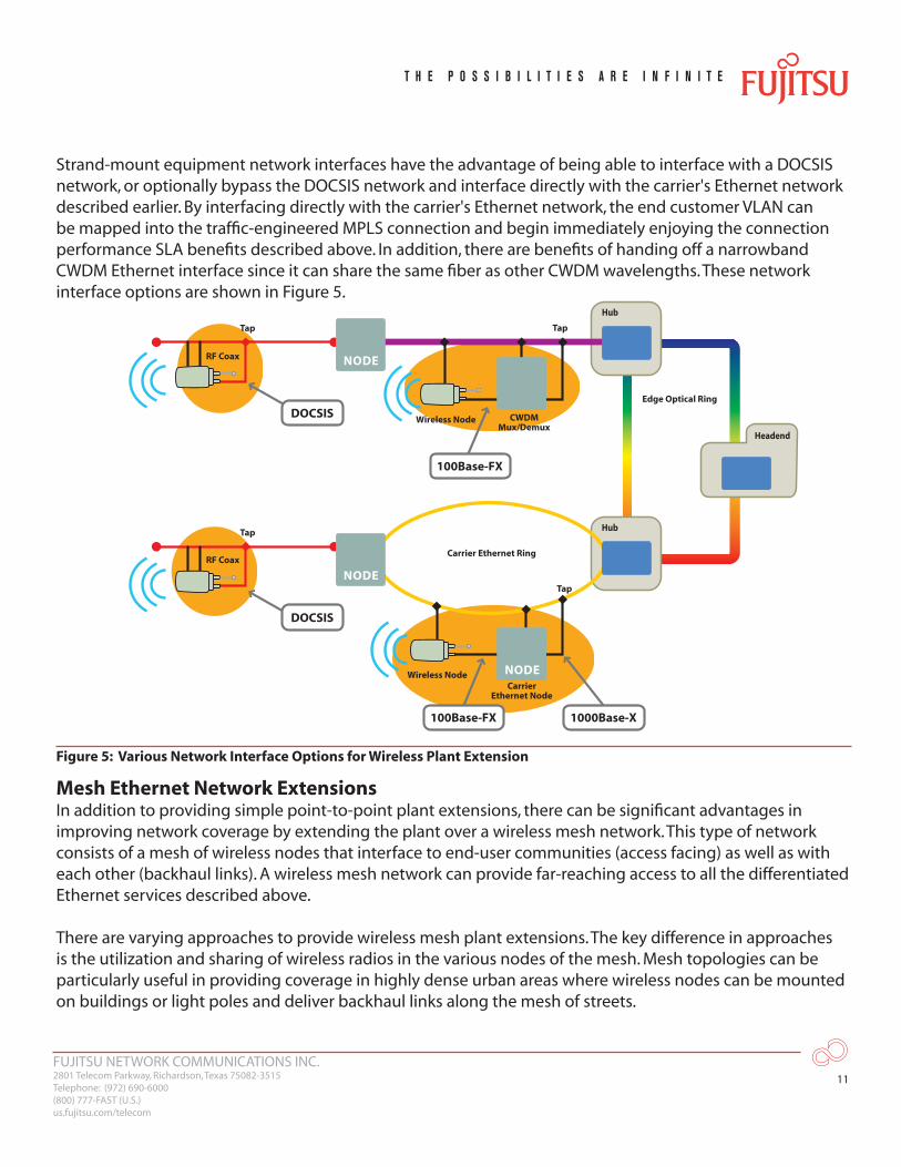
Strand-mount equipment network interfaces have the advantage of being able to interface with a DOCSIS network, or optionally bypass the DOCSIS network and interface directly with the carrier's Ethernet network described earlier. By interfacing directly with the carrier's Ethernet network, the end customer VLAN can be mapped into the traffic-engineered MPLS connection and begin immediately enjoying the connection performance SLA benefits described above. In addition, there are benefits of handing off a narrowband CWDM Ethernet interface since it can share the same fiber as other CWDM wavelengths. These network interface options are shown in Figure 5.
Headend
Hub
Hub
100Base-FX
Wireless Node
Tap
Tap
CarrierEthernet Node
1000Base-X
DOCSIS
NODE
Edge Optical Ring
Carrier Ethernet Ring
NODE
Tap
RF Coax
RF Coax
DOCSIS
NODE
100Base-FX
Wireless Node
Tap
CWDMMux/Demux
Figure 5: Various Network Interface Options for Wireless Plant Extension
Mesh Ethernet Network ExtensionsIn addition to providing simple point-to-point plant extensions, there can be significant advantages in improving network coverage by extending the plant over a wireless mesh network. This type of network consists of a mesh of wireless nodes that interface to end-user communities (access facing) as well as with each other (backhaul links). A wireless mesh network can provide far-reaching access to all the differentiated Ethernet services described above.
There are varying approaches to provide wireless mesh plant extensions. The key difference in approaches is the utilization and sharing of wireless radios in the various nodes of the mesh. Mesh topologies can be particularly useful in providing coverage in highly dense urban areas where wireless nodes can be mounted on buildings or light poles and deliver backhaul links along the mesh of streets.
FUJITSU NETWORK COMMUNICATIONS INC.2801 Telecom Parkway, Richardson, Texas 75082-3515Telephone: (972) 690-6000(800) 777-FAST (U.S.)us.fujitsu.com/telecom
12
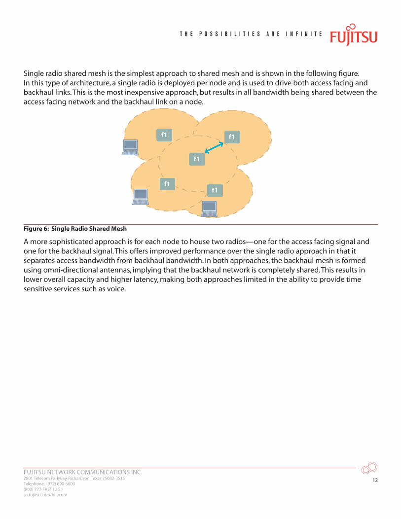
Single radio shared mesh is the simplest approach to shared mesh and is shown in the following figure. In this type of architecture, a single radio is deployed per node and is used to drive both access facing and backhaul links. This is the most inexpensive approach, but results in all bandwidth being shared between the access facing network and the backhaul link on a node.
f1
f1f1
f1f1
Figure 6: Single Radio Shared Mesh
A more sophisticated approach is for each node to house two radios—one for the access facing signal and one for the backhaul signal. This offers improved performance over the single radio approach in that it separates access bandwidth from backhaul bandwidth. In both approaches, the backhaul mesh is formed using omni-directional antennas, implying that the backhaul network is completely shared. This results in lower overall capacity and higher latency, making both approaches limited in the ability to provide time sensitive services such as voice.
FUJITSU NETWORK COMMUNICATIONS INC.2801 Telecom Parkway, Richardson, Texas 75082-3515Telephone: (972) 690-6000(800) 777-FAST (U.S.)us.fujitsu.com/telecom
13
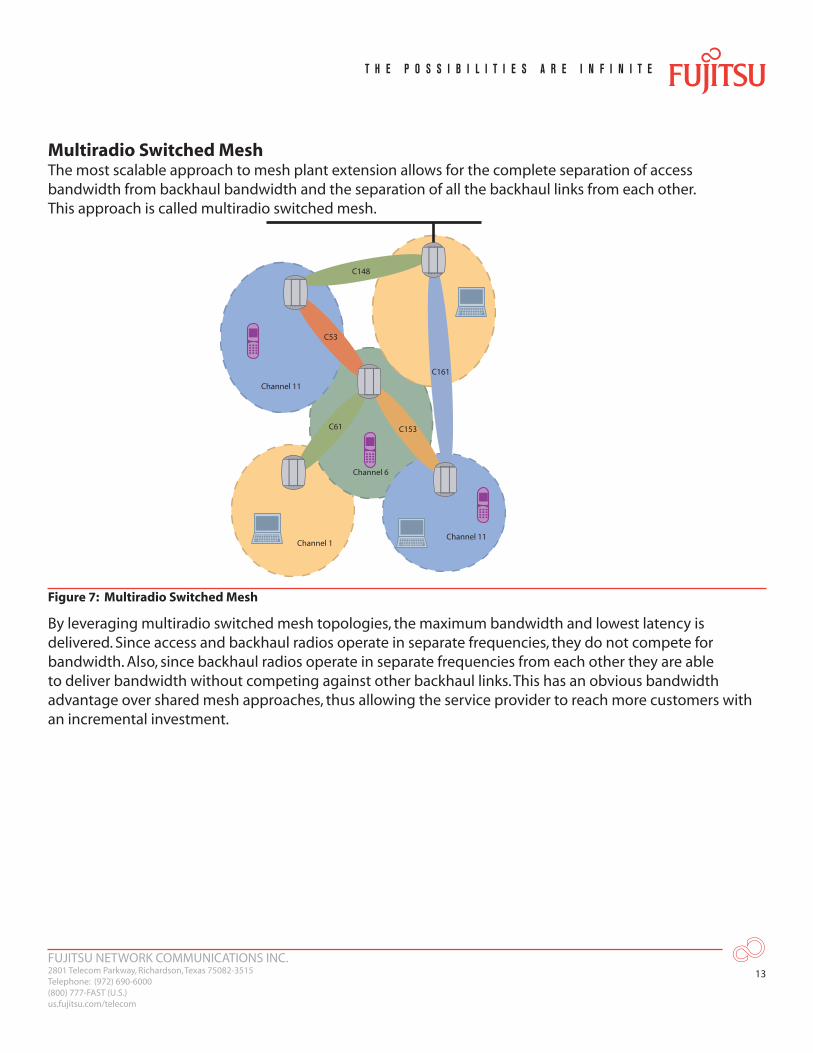
Multiradio Switched MeshThe most scalable approach to mesh plant extension allows for the complete separation of access bandwidth from backhaul bandwidth and the separation of all the backhaul links from each other. This approach is called multiradio switched mesh.
C161
C153
C148
C53
Channel 11
Channel 11
Channel 6
Channel 1
C61
Figure 7: Multiradio Switched Mesh
By leveraging multiradio switched mesh topologies, the maximum bandwidth and lowest latency is delivered. Since access and backhaul radios operate in separate frequencies, they do not compete for bandwidth. Also, since backhaul radios operate in separate frequencies from each other they are able to deliver bandwidth without competing against other backhaul links. This has an obvious bandwidth advantage over shared mesh approaches, thus allowing the service provider to reach more customers with an incremental investment.
FUJITSU NETWORK COMMUNICATIONS INC.2801 Telecom Parkway, Richardson, Texas 75082-3515Telephone: (972) 690-6000(800) 777-FAST (U.S.)us.fujitsu.com/telecom
14
0
8
16
20
4
12
6
14
18
2
10
0
160
200
40
120
60
140
180
20
100
2 6 10 14 184 8 12 16 20 2 6 10 14 184 8 12 16 20Number of Access Points Number of Access Points
Per
-AP
Acc
ess
Cap
acit
y (M
bp
s)
Multiradio SwitchedDual Radio SharedSingle Radio Shared
80
Per Node Access Radio Capacity Overall Network Capacity
Syst
em C
apac
ity
(Mb
ps)
Multiradio SwitchedDual Radio SharedSingle Radio Shared
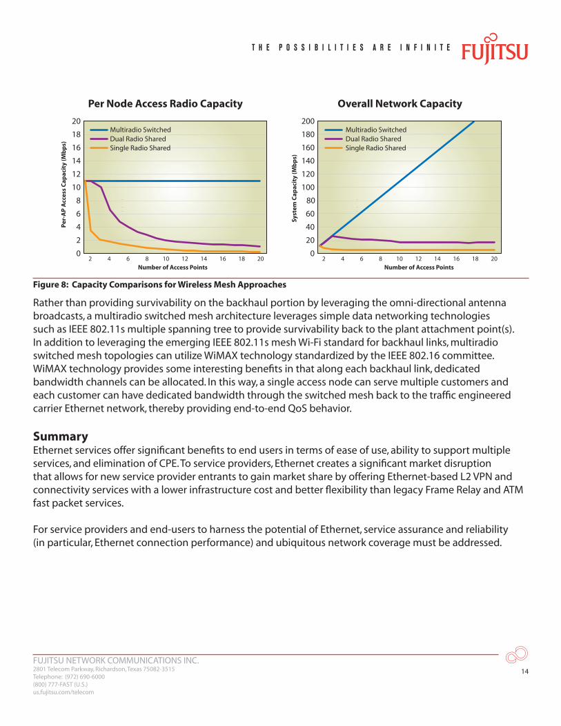
Figure 8: Capacity Comparisons for Wireless Mesh Approaches
Rather than providing survivability on the backhaul portion by leveraging the omni-directional antenna broadcasts, a multiradio switched mesh architecture leverages simple data networking technologies such as IEEE 802.11s multiple spanning tree to provide survivability back to the plant attachment point(s). In addition to leveraging the emerging IEEE 802.11s mesh Wi-Fi standard for backhaul links, multiradio switched mesh topologies can utilize WiMAX technology standardized by the IEEE 802.16 committee. WiMAX technology provides some interesting benefits in that along each backhaul link, dedicated bandwidth channels can be allocated. In this way, a single access node can serve multiple customers and each customer can have dedicated bandwidth through the switched mesh back to the traffic engineered carrier Ethernet network, thereby providing end-to-end QoS behavior.
SummaryEthernet services offer significant benefits to end users in terms of ease of use, ability to support multiple services, and elimination of CPE. To service providers, Ethernet creates a significant market disruption that allows for new service provider entrants to gain market share by offering Ethernet-based L2 VPN and connectivity services with a lower infrastructure cost and better flexibility than legacy Frame Relay and ATM fast packet services.
For service providers and end-users to harness the potential of Ethernet, service assurance and reliability (in particular, Ethernet connection performance) and ubiquitous network coverage must be addressed.
FUJITSU NETWORK COMMUNICATIONS INC.2801 Telecom Parkway, Richardson, Texas 75082-3515Telephone: (972) 690-6000(800) 777-FAST (U.S.)us.fujitsu.com/telecom
15
Connection-oriented Ethernet services that leverage traffic-engineered MPLS technology can be used to uniquely provide guaranteed Ethernet services that provide differentiation against embedded solutions that often have significant limitations in the types of SLAs that can be offered.
To provide wide-scale access to these solutions and reach the large number of unreachable potential subscribers, mesh-based and point-to-point wireless on-ramps with standards-based Ethernet, CWDM and DOCSIS handoffs, can be used to augment fiber access. A mesh-based topology extends the fiber plant in highly dense urban areas. A variety of mesh architectures ranging from simple single radio shared mesh to multi-radio switched mesh can be integrated with the carrier's Ethernet network to reach the maximum number of potential customers with higher bandwidth and multiservice capable latency performance.
References[1] WiMAX – Enabling SME Commercial Services, R. Eisenach, SCTE Commercial Services Symposium,
October, 2005, Charlotte, NC[2] Metro Ethernet Forum, MEF 6, Ethernet Services Definitions – Phase I, June, 2004.[3] Metro Ethernet Forum, MEF 10, Ethernet Services Attributes, Phase 1, November, 2004.[4] Metro Ethernet Forum, MEF 4, Metro Ethernet Network Architecture Framework – Part 1: Generic
Framework, May, 2004.[5] IETF RFC 3031 Multiprotocol Label Switching Architecture, E. Rosen, et. al., January, 2001.[6] IETF RFC 3032 MPLS Label Stack Encoding, E. Rosen, et. al. January, 2001.[7] Ethernet Services Carrier Scorecard: North America. Vol. 3, No. 7, April, 2005[8] Yankee Group 2005 Metro Ethernet Survey (US)[9] IETF draft-ietf-pwe3-ethernet-encap-11.txt, Encapsulation Methods for Transport of Ethernet over MPLS
Networks, L. Martini, et. al, November 2005.[10] IETF RFC 3209, RSVP-TE: Extensions to RSVP for LSP Tunnels, D. Awduche, et. al., December 2001[11] IETF draft-ietf-ospf-te-node-addr-02, Advertising a Router's Local Addresses in OSPF TE Extensions,
R. Aggarwal, K. Kompella, September, 2005.[12] IEEE 802.1Q – 2003, Virtual Bridged Local Area Networks[13] ITU Y.1710 Requirements for Operations & Maintenance functionality for MPLS Networks[14] ITU Y.1711 Operation & Maintenance Mechanism for MPLS Networks[15] IEEE RFC 4090, Fast Reroute Extensions to RSVP-TE for LSP Tunnels, May, 2005[16] IEEE 802.11b[17] IEEE 802.11a/g
FUJITSU NETWORK COMMUNICATIONS INC.2801 Telecom Parkway, Richardson, Texas 75082-3515Telephone: (972) 690-6000(800) 777-FAST (U.S.)us.fujitsu.com/telecom
16
© Copyright 2006 Fujitsu Network Communications Inc. FUJITSU (and design)® and THE POSSIBILITIES ARE INFINITE™ are trademarks of Fujitsu Limited. All Rights Reserved. All other trademarks are the property of their respective owners.
Acronym Descriptor
AAA Authentication, Authorization and Accounting
APS Automatic Protection Switching
ATM Asynchronous Transfer Mode
CAC Connection Admission Control
CPE Customer Premises Equipment
CSMA/CD Carrier Sense Multiple Access with Collision Detection
CWDM Course Wavelength Division Multiplexing
DOCSIS Data Over Cable Service Interface Specification
ELAN Ethernet Local Area Network
E-Line Ethernet Line
EVC Virtual Connection
GHz Gigahertz
HFC Hybrid Fiber Coax
IEEE Institute of Electrical and Electronics Engineers
IETF Internet Engineering Task Force
IP Internet Protocol
ISP Internet Service Provider
Kbps Kilobits per second
LAN Local Area Network
LDP Label Distribution Protocol
MAC Medium Access Control
Acronym Descriptor
Mbps Megabits per second
MEF Metro Ethernet Forum
MPLS Multi-Protocol Label Switching
ms millisecond
MSO Multiple System Operator
OAM Operations, Administration and Maintenance
OSPF-TE Open Shortest Path First with Traffic Engineering
OTN Optical Transport Network
QoS Quality of Service
RSVP-TE Resource Reservation Protocol with Traffic Engineering
SLA Service Level Agreement
SMB Small to Medium Business
SSID Service Set IDentifier
TDM Time Division Multiplexing
UNI User Network Interface
VC Virtual Connection
VPN Virtual Private Network
VLAN Virtual Local Area Network
WDM Wavelength Division Multiplexing
Wi-Fi Wireless Fidelity
Related Documents