Warning – Uncontrolled when printed Document Number: MEFA0001 Page 1 of 38 Issue Date: 23/02/2018 Document Owner: Reliability Planning Manager, SP&AS Version Number: 7 Next review Date: 28/12/2018 MAINTENANCE RELATED CLAUSES FOR CAPITAL AND OPERATIONAL PROJECTS Version 8

Welcome message from author
This document is posted to help you gain knowledge. Please leave a comment to let me know what you think about it! Share it to your friends and learn new things together.
Transcript

Warning – Uncontrolled when printed
Document Number: MEFA0001 Page 1 of 38 Issue Date: 23/02/2018
Document Owner: Reliability Planning Manager, SP&AS
Version Number: 7 Next review Date: 28/12/2018
MAINTENANCE RELATED CLAUSES FOR CAPITAL AND OPERATIONAL PROJECTS
Version 8

Warning – Uncontrolled when printed
Document Number: MEFA0001 Page 2 of 38 Issue Date: 23/02/2018
Document Owner: Reliability Planning Manager, SP&AS
Version Number: 8 Next review Date: 28/12/2018
Contents Executive Summary ............................................................................................................ 4
1. Planning and Design Stage Activities ........................................................................ 6
1.1 Concept Design/Planning Stage ............................................................................. 6
1.2 Design Stage .......................................................................................................... 6
1.2.1 Reliability Studies and Asset Selection ............................................................ 6
1.2.2 Commissioning Plans ...................................................................................... 7
2. Sydney Water CAD requirements ............................................................................... 7
2.1.1 Summary of copies required for submission by the Contractor ................ Error!
Bookmark not defined.
3. Enterprise Asset Management System (Maximo) ...................................................... 7
4. Asset Identification ...................................................................................................... 8
4.1 General ................................................................................................................... 8
4.2 Facility Code or Location Code ............................................................................... 8
4.3 Asset Information .................................................................................................... 9
4.4 Data Verification ................................................................................................... 10
5 Labelling and Identification ....................................................................................... 10
5.1 General Requirements .......................................................................................... 10
5.2 Label Dimensions ................................................................................................. 10
5.3 Label Materials ..................................................................................................... 10
5.4 Font Sizes ............................................................................................................. 11
5.5 Installation of Labels ............................................................................................. 11
5.6 Examples of Labelling ........................................................................................... 12
5.7 Survey Datum Marks ............................................................................................ 13
5.8 MGA coordinate .................................................................................................... 13
6 Operational and Maintenance Manuals .................................................................... 13
6.1 Type of O&M Manuals .......................................................................................... 13
6.2 O&M Manuals (Applicable to all facilities other than WWTPs, WFPs & WRPs) ..... 16
6.3 Manufacturer’s Instructions Manuals ..................................................................... 17
7 Testing and Commissioning ..................................................................................... 17
7.1 General ................................................................................................................. 17
7.2 Commissioning Process........................................................................................ 18
7.3 Commissioning Plan and Testing .......................................................................... 19

Warning – Uncontrolled when printed
Document Number: MEFA0001 Page 3 of 38 Issue Date: 23/02/2018
Document Owner: Reliability Planning Manager, SP&AS
Version Number: 8 Next review Date: 28/12/2018
7.4 Scheduled Dates for Testing and Commissioning ................................................. 20
7.5 Testing .................................................................................................................. 21
7.5.1 Pre- Factory Acceptance Testing (for electrical equipment) ........................... 21
7.5.2 Factory Acceptance Testing ........................................................................... 21
7.5.3 Pre Site Acceptance Testing .......................................................................... 25
7.6 Testing and Commissioning Record Sheets .............................................................. 31
8 Operational and Maintenance Training .................................................................... 32
9 Handover of Assets ................................................................................................... 33
10 Handover of Documents ............................................................................................ 34
10.1 File naming convention ............................................................................................ 34
11 Critical Spare Parts and Special Tools ..................................................................... 36
12 Warranties .................................................................................................................. 36
Definitions ......................................................................................................................... 37
Document Change Summary ........................................................................................... 38

Warning – Uncontrolled when printed
Document Number: MEFA0001 Page 4 of 38 Issue Date: 23/02/2018
Document Owner: Reliability Planning Manager, SP&AS
Version Number: 8 Next review Date: 28/12/2018
Executive Summary All capital and operational project deliverables need to meet the requirements of the Asset
Maintenance Policy AMQ0002. This policy applies to all assets delivering water, waste water,
recycled water and stormwater services including information systems and property.
The clauses contained in this document are designed to support the above policy and apply
to all asset creation and operating phase work carried out for Sydney Water as well as to the
developer funded works.
The Maintenance Related Clauses for Capital and Operational projects apply to all Sydney
Water facilities.
Planning and Design Stage Activities need to include a process level risk assessment and
equipment level risk assessment called the Failure Mode Effects and Criticality Analysis
(FMECA) and a Reliability Block Diagram (RBD). These are undertaken at the concept design
stage to develop contingency plans and manage risks by the Contractor.
For all drawings shall refer to Computer Aided Drafting (CAD) Standard for Engineering drawings.
Enterprise Asset Management System (MAXIMO) will be used for storage of asset related
data. The Contractor is responsible for entry of asset details into MAXIMO. Details of spare
parts and decommissioned assets will be provided by the Contractor via the spreadsheet(s)
specified by the Principal. Entry of asset details will require access to the MAXIMO system.
Sydney Water Project Manager will follow procedures to provide access to the contractor.
For new facilities, an Asset Identification will be created by the Principal in Maximo with a
unique asset number, based on data supplied by the Contractor. Standard templates are
available from the Principal to assist in this process.
Labelling and Identification will be provided by the Contractor as per the specification
provided by the Principal. This is to ensure that labels are consistent on all Sydney Water
assets.
Operation and Maintenance Manuals will be submitted in the format and with the number of
copies specified by the Principal. It is particularly important that the document chapters are as
per the standard template to avoid resubmissions and reviews which can be time consuming
both to the Contractor and the Principal.
A Testing and Commissioning procedure will be developed by the Contractor for approval
by the Principal, unless otherwise specified in the contract. This is to ensure that that the
Contractor has followed the relevant clauses during the commissioning phase in conjunction
with the Principal’s approval, as required by the Contract.
Hand-Over Documents will be submitted according to the format and number of copies
specified by the Principal. Site works remain the responsibility of the Contractor until the
completion of Contract. The Contractor will ensure all documents submitted are accompanied
by an electronic document transmittal form to avoid time consuming resubmissions, reviews
and amendments.

Warning – Uncontrolled when printed
Document Number: MEFA0001 Page 5 of 38 Issue Date: 23/02/2018
Document Owner: Reliability Planning Manager, SP&AS
Version Number: 8 Next review Date: 28/12/2018
For new assets, any Critical Spare Parts and Special Tools for maintenance purposes will
be supplied by the Contractor to the Principal prior to Completion of Contract. This will ensure
all critical spares are in stock with the Principal to avoid procurement at a later date where the
costs of items might vary upon the time of installation and avoid accidental failures that might
occur during the hand over stage.
For new assets, the contractor shall provide the Principal’s nominated staff with Operational
and Maintenance Training to explain all aspects of operation and maintenance where assets
can be reliably, effectively and safety operated and maintained under all conditions without
supervision.
Warranties will be obtain by the Contractor as specified in the contract to ensure the Principal
will have the benefit of warranties specified in the Contract obtained by subcontractors.

Warning – Uncontrolled when printed
Document Number: MEFA0001 Page 6 of 38 Issue Date: 23/02/2018
Document Owner: Reliability Planning Manager, SP&AS
Version Number: 8 Next review Date: 28/12/2018
1. Planning and Design Stage Activities
1.1 Concept Design/Planning Stage A process level risk assessment Failure Mode Effects and Criticality Analysis (FMECA) and
a Reliability Block Diagram (RBD) shall be undertaken at the concept design stage to develop
contingency plans and manage risks. The Principal can supply a sample document, upon
request.
The responsibility to carry out this work rests with the Contractor. The Contractor may be
required to engage a competent FMECA facilitator to co-ordinate this work, if these expertise
are not available within the Contractor’s organisation. The FMECA facilitator is required to co-
ordinate the work with the designers and Principal’s stakeholders including planners,
operators and maintainers.
Asset selection shall be based on minimizing the total life cycle costs. Where possible, assets
selected should be consistent with similar existing assets performing reliably within the
operating facilities owned by the Principal. The Designer must seek advice from Principal’s
relevant engineering representative during the asset selection process. This clause is not
meant to discourage innovative solutions.
Where available, the Principal will provide to the Contractor FMECA assessments and RBD
previously carried out for reasonably similar projects. The existing assessments, if applicable,
may be modified and adopted with necessary amendments to meet the requirements in the
current application.
The basis of selection of processes and assets shall be to minimise life cycle costs.
1.2 Design Stage
1.2.1 Reliability Studies and Asset Selection
An equipment level risk assessment (FMECA) and a detailed RBD shall be prepared at the
detailed design stage to:
• Identify monitoring requirements for assessed risks
• Identify spares to be kept by Sydney Water, and
• Develop and provide Maintenance Plans
Assets are to be disaggregated on a process basis to the equipment level.
The Contractor may be required to engage a competent FMECA facilitator to co-ordinate this
work, if these expertise are not available within the Contractor’s organisation. The FMECA
facilitator is required to co-ordinate the work with the designers and Principal’s stakeholders
including planners, operators and maintainers.
The equipment level risk assessment (FMECA) and RBD are to be updated following
commissioning to reflect the “as built” condition of the assets and submitted to the Principal
prior to hand-over of the assets.

Warning – Uncontrolled when printed
Document Number: MEFA0001 Page 7 of 38 Issue Date: 23/02/2018
Document Owner: Reliability Planning Manager, SP&AS
Version Number: 8 Next review Date: 28/12/2018
It is important for the designer to consider the access requirements for maintenance of
equipment. All lubrication points and other maintenance inspection points must be positioned
where they can be easily reached. Consideration must also be given to lifting and easy
removal or exchange of components when renewals or refurbishments are required. It is the
responsibility of the Contractor to ensure that the designer takes these into account in the
design.
In addition to maintenance and reliability requirements, asset selection shall be based on
minimizing the total life cycle costs. Where possible, assets selected should be consistent
with similar existing assets performing reliably within the operating facilities owned by the
Principal. The Designer must seek advice from Principal’s relevant engineering representative
during the asset selection process. This clause is not meant to discourage innovative
solutions.
Where available, the Principal will provide to the Contractor FMECA assessments and RBD
previously carried out for reasonably similar projects. The existing assessments, if applicable,
may be modified and adopted with necessary amendments to meet the requirements in the
current application.
1.2.2 Commissioning Plans
During design stage, the Contractor shall prepare a commissioning plan and a series of
Inspection and Test Plans (ITPs) setting out all tests to be undertaken to prove that the
completed works meet the performance requirements of the design and the Contract.
The commissioning plan and ITPs shall be submitted to the Principal for review and approval.
2. Sydney Water CAD requirements Sydney Water CAD templates are available on the Sydney Water website.
The Contractor shall submit all WAC drawings, as follows:
Electronic copies (CD-R/DVD/USB)
1 copies – Distribution (Plan Room & In AutoCAD format, PDF format and Meta data
CSV file.
3. Enterprise Asset Management System (Maximo) During completion of the installation work (and no later than 20 working days prior to
handover), the Contractor is responsible for collation and compilation of necessary information
in the required format for inclusion in MAXIMO. The Contractor is responsible for entry of asset
details into MAXIMO. Details of spare parts and decommissioned assets will be provided by
the Contractor via the spreadsheet(s) specified by the Principal.
Entry of asset details will require access to the MAXIMO system. Sydney Water Project
Manager to provide access to the contractor. Training documentation and instructional DVD
are available from the Principal on request.

Warning – Uncontrolled when printed
Document Number: MEFA0001 Page 8 of 38 Issue Date: 23/02/2018
Document Owner: Reliability Planning Manager, SP&AS
Version Number: 8 Next review Date: 28/12/2018
The Contractor shall liaise with the Principal before data entry is commenced to ensure that
data entry standards and the Principal’s requirements are fully understood. A Specialist from
the Principal will be available for consultation on matters involving data entry.
Data to be supplied under this Clause can be submitted to the Principal at any stage
throughout the duration of the project. Completion of data entry by the contractor shall be at
least 20 working days prior to commencement of hand over, for a joint review and acceptance
by the Principal.
The Project Manager shall request verification at least 20 working days prior to hand over.
The Principal will issue a Verification Certificate upon satisfactory verification of supplied data.
It shall be the responsibility of the Contractor to carry out amendments requested by the
Principal and submit amended documentation in the required formats prior to hand over of
assets. All revisions to location/asset data resulting from changes carried out during hand over
shall be submitted to the Principal within no later than 20 working days after hand over.
4. Asset Identification
4.1 General In general terms, an asset refers to a physical asset such as plant, equipment or structure.
Certain plants are classified as Facilities in Sydney Water and the equipment within such
facilities are termed Assets.
For all types of facilities and assets the contractor shall refer to the Asset Identification Policy
ACP0001 and the Asset Numbering Standard Operating Procedure ACP0055, both of which
can be obtained from the Principal if required
In Maximo each Facility or Asset is identified with a unique number, which is termed a
“Location Code”. The Principal is responsible for allocation of Facility Code and Location Code
based on the Sydney Water Asset Identification Policy ACP0001. The contractor is
responsible for requesting Facility Number(s) (if not already requested) and Location
Number(s) for new Assets at design stage.
4.2 Facility Code or Location Code The Principal will issue Facility Codes or Location Codes to the Contractor for all new locations
to be provided under the Contract. For the purpose of issuing Location Numbers (up to 400
locations), the Principal requires 10 working days from the date of receipt of the relevant
inputs. For projects requiring more than 400 location numbers, requests for numbers can be
released in batches not exceeding 400, or the additional time required for issuing of location
numbers shall be discussed and agreed mutually. Additional time may be required if the
information provided by the Contractor is incomplete and requires clarification.
The contractor shall request Facility or Location codes using standard templates which are
available from the Principal. The information supplied in each request spreadsheet shall relate
to only one Project. A contractor working on multiple projects for the Principal shall, where

Warning – Uncontrolled when printed
Document Number: MEFA0001 Page 9 of 38 Issue Date: 23/02/2018
Document Owner: Reliability Planning Manager, SP&AS
Version Number: 8 Next review Date: 28/12/2018
required to supply information, do so using a separate spreadsheet for each project.
Contractor requests shall be provided to the Principal via Sydney Water Project Manager.
Contractor requests for location codes shall be accompanied by a Process and
Instrumentation Diagram (P&IDs).
Upon receipt of a Facility number request form, the Principal will issue Facility Numbers from
MAXIMO. The Principal may seek additional information on the location of the Facility, where
required. The Principal will return the Facility number request spreadsheet containing the
allocated Facility Code to the Contractor.
Upon receipt of a Location number request form, the Principal will issue Location Numbers
and enter these numbers into MAXIMO. The Principal will return Location number request
spreadsheet containing the allocated location numbers and relevant external reference
number to the Contractor. The Contractor shall then amend the P&IDs and other relevant
documentation, by replacing the provisional Location Numbers with the allocated Location
Numbers.
If the Principal identifies from the Contractor’s P&IDs and location layout drawings that there
are location(s) not included in their Location number request spreadsheet, which require
Location Numbers, the Principal will allocate these additional Location Numbers. The
Contractor shall include the additional Location Numbers (and their corresponding locations)
in the P&IDs and other relevant documentation.
The Contractor is responsible for providing information on existing locations and assets made
redundant (decommissioned) or replaced by the project, using standard templates available
from the Principal. The information shall be provided to the Principal, via Sydney Water Project
Manager, most appropriately at the same time the contractor is requesting new location codes,
but no later than 20 working days prior to commencement of hand over.
4.3 Asset Information Asset information is to be entered directly into MAXIMO via the ‘Contractor Asset Update
Application’ and submit for ‘Validation’ by the Principal at least 20 working days prior to the
commencement of hand over. This will require access to the Sydney Water MAXIMO
application for data entry personnel. The Project Manager / SWC Representative shall arrange
MAXIMO access for the contractor’s data entry personnel.
The Contractor is responsible for creating asset numbers and entering asset specifications in
Maximo. The Contractor shall comply with the Asset Identification Policy ACP0001 and the
Asset Numbering Standard Operating Procedure ACP0055 when entering asset data. The
Principal has tools available to assist in entering asset information.
Principle will validate asset data supplied by contractor and notify the contractor via Project
Manager of any issues that need to be resolved.
For the purpose of validating asset data (up to 400 locations), the Principal requires 10 working
days from the date of notification. For projects requiring more than 400 location numbers,
requests for validation can be released in batches not exceeding 400, or the additional time

Warning – Uncontrolled when printed
Document Number: MEFA0001 Page 10 of 38 Issue Date: 23/02/2018
Document Owner: Reliability Planning Manager, SP&AS
Version Number: 8 Next review Date: 28/12/2018
required for validation shall be discussed and agreed mutually. Additional time may be
required if the information provided by the Contractor is incomplete and requires clarification.
4.4 Data Verification Sydney Water Project Manager shall request Verification Certificate from Asset Data
Management to ensure the required asset information has been provided by the project. The
request shall include a list of locations requested along with final P&IDs, a list of redundant or
replaced assets. The request shall be made at least 20 working days prior to the
commencement of hand over.
A representative of the Principal will issue a Verification Certificate after satisfactory
verification of asset information provided by the project. Any issues or concerns identified
during verification shall to be resolved prior of issuing of the Verification Certificate. Verification
Certificate is a prerequisite for project handover and Commissioning Engineer will require this
certificate at the handover of any project.
5 Labelling and Identification
5.1 General Requirements The Contractor shall supply and install labels to identify locations in accordance with the
location numbers issued by the Principal. Where no such identification is available, the
Contractor shall seek the Principal’s direction as to the identification to be used. This will be
referred to the Asset Identification Policy DRAFT followed by Asset Numbering Procedure and
Asset Hierarchy Procedure.
In cases where there are two contractors working within one facility, eg: Vacuum systems, the
contractor working inside the building for all electrical and mechanical assets shall provide
Sydney Water approved labelling. The contractor working outside the building including civil,
mechanical and site within the facility grounds shall provide all Sydney Water approved
labelling.
5.2 Label Dimensions The size of the label shall be determined by the number of letters, size of letters, space
available to install the label and the text shall be understood without ambiguity. The location
number shall remain on a single line.
5.3 Label Materials All labels that are subjected to the weather, e.g. installed on outdoor enclosures such as
kiosks, cubicles, buildings etc, are to be 1.2 mm thick, 316 Stainless Steel, 0.2 mm engraved
and in-filled with black paint. Labels in chemical contact process areas shall be treated
similarly.
All labels that are within enclosures or buildings shall be of Traffolyte or similar material with
black lettering engraved on a white background, unless specifically nominated otherwise.
Edges of labels shall be bevelled on all sides. Shutdown system labels (example emergency
stop buttons) and warning labels will be white lettering engraved on a red background.

Warning – Uncontrolled when printed
Document Number: MEFA0001 Page 11 of 38 Issue Date: 23/02/2018
Document Owner: Reliability Planning Manager, SP&AS
Version Number: 8 Next review Date: 28/12/2018
Labels installed in corrosive environments such as wet wells maintenance holes and the like
shall be made of stainless steel and fixed with a minimum of two stainless steel screws. Labels
identifying physical assets i.e. wet wells, motors, instruments shall be visible without the
removal of a cover or access lid. The manufacturer’s nameplate, attached to the assets
installed under the Contract, shall be in addition to the Location Number label described above
and shall be visible from the access position.
If Contractor is in doubt, communication between the Principal and the Contractor shall take
place for confirmation on label material.
5.4 Font Sizes All label lettering shall be in “CAPITAL” and “ARIAL” font. The wording on the labels shall be horizontal. Unless otherwise stated elsewhere in the Contract documents, the following font sizes are applicable.
a) Facility Numbers such as SP1140 on kiosks or equipment enclosures should be 12 mm and on superstructures (eg SP1139) 100 mm high.
b) Where permissible (except for physically small assets) font size 10 mm shall be used for location labels. For very small assets, the font size may be reduced to fit. The exceptions to this rule are listed below.
c) Location number labels for electrical components shall be 4 mm. d) In certain facilities such as SPSs, and WPSs, a pump unit number may be
specified in the drawings. In such cases, the Pump Unit Number label shall have a font size of 50 mm.
e) The labels that describe operating procedures shall have headings of 6 mm and the content shall be of 4 mm.
5.5 Installation of Labels All stainless steel labels shall be secured using stainless steel fixtures. The Traffolyte labels on front panels of switchgear & control assemblies shall be secured using stainless steel fixtures. Gluing is not acceptable. Self-adhesive Traffolyte labels, where the adhesive covers the complete back plane of the labels, are acceptable for use inside enclosures, buildings and switchgear & control assemblies. To prevent re-doing the labels after maintenance/replacement of the equipment, the location labels shall not be directly secured to replaceable components. For such assets, the labels shall be installed on a permanent structure as close as possible to the equipment. For example, the valve label shall not be fixed to the valve body but could be mounted on a
suitable bracket on the valve flange or valve-supporting plinth, except in the case of small
valves where a hanging label fixed with stainless steel wire is acceptable.
When labels are fitted close to access covers, they must visible with the cover in both open and closed positions. The labels for electrical equipment within cubicles shall be on the mounting plate. Attaching labels to cable trays and other removable parts is not acceptable. All inscriptions on the labels shall be visible from the ground or a level platform.

Warning – Uncontrolled when printed
Document Number: MEFA0001 Page 12 of 38 Issue Date: 23/02/2018
Document Owner: Reliability Planning Manager, SP&AS
Version Number: 8 Next review Date: 28/12/2018
If Contractor is in doubt on location of an asset label, communication between the Principal
and the Contractor shall take place for a confirmation on exact location before printing.
5.6 Examples of Labelling Facility Number SP1139 (for example)
Description of asset Inlet Penstock
Location Number allocated by Maximo SP1139PEN01
Location Number in the drawings PEN01 (exclude facility no.)
Field Label
PEN01
INLET PENSTOCK

Warning – Uncontrolled when printed
Document Number: MEFA0001 Page 13 of 38 Issue Date: 23/02/2018
Document Owner: Reliability Planning Manager, SP&AS
Version Number: 8 Next review Date: 28/12/2018
Exemptions to labelling rules
a) Where labeling requirements are specifically stated in the Principal approved drawing/s, Contractor shall comply with such instructions instead of the labeling requirements under this clause.
b) Under special circumstances, for example, where locations belonging to two facilities are physically in close proximity to each other or where a location is remote from the parent facility, the Principal may request the Contractor to include the facility number in the labels. e.g. SP1139PEN01 instead of PEN01
Field Label Example
c) for specific assets including High Voltage assets, sewer gauges and vacuum sewerage systems, reference to these rules will be referred to Asset Numbering guidelines and procedures
d) the Contractor is uncertain of labelling requirements, clarifications should be sought from the Principal.
5.7 Survey Datum Marks During construction of wet wells Survey Datum reference marks with labels shall be installed on the wet well roof slab, on the top of the inlet maintenance hole, on top of emergency storage tank and wherever else level measuring instruments and/or switches are installed. Sitting of survey reference marks and labels shall be as close as possible to the instruments as follow:
• Wet Well – on the roof slab adjacent to the instrument access hatch.
• IMH – on the rim of the MH above the instruments.
• Storage Chambers – on the roof slab adjacent to the instrument access hatch.
• The reference mark label shall clearly indicate the reduced level and datum e.g. RL 123.45 AHD.
5.8 MGA coordinate For all WAC MGA submissions should follow the design criteria as per the current WSAA codes.
6 Operational and Maintenance Manuals The requirements for the Treatment Plants are different from that of the network facilities like
pumping stations and reservoirs. Detailed requirements are specified in Sections 6.2 & 6.3
below.
6.1 Type of O&M Manuals O & M Manuals can be prepared at Process Level, Area Level or Equipment / Asset Level.
Depending on the Contract, the Contractor shall discuss and agree with the Principal on the
type/s of O & M Manuals required. Each manual shall have a content page indicating the chapters
and corresponding page numbers.
SP1139PEN01
INLET PENSTOCK
Warning – Uncontrolled when printed
Document Number: MEFA0001 Page 14 of 38 Issue Date: 23/02/2018
Document Owner: Reliability Planning Manager, SP&AS
Version Number: 8 Next review Date: 28/12/2018
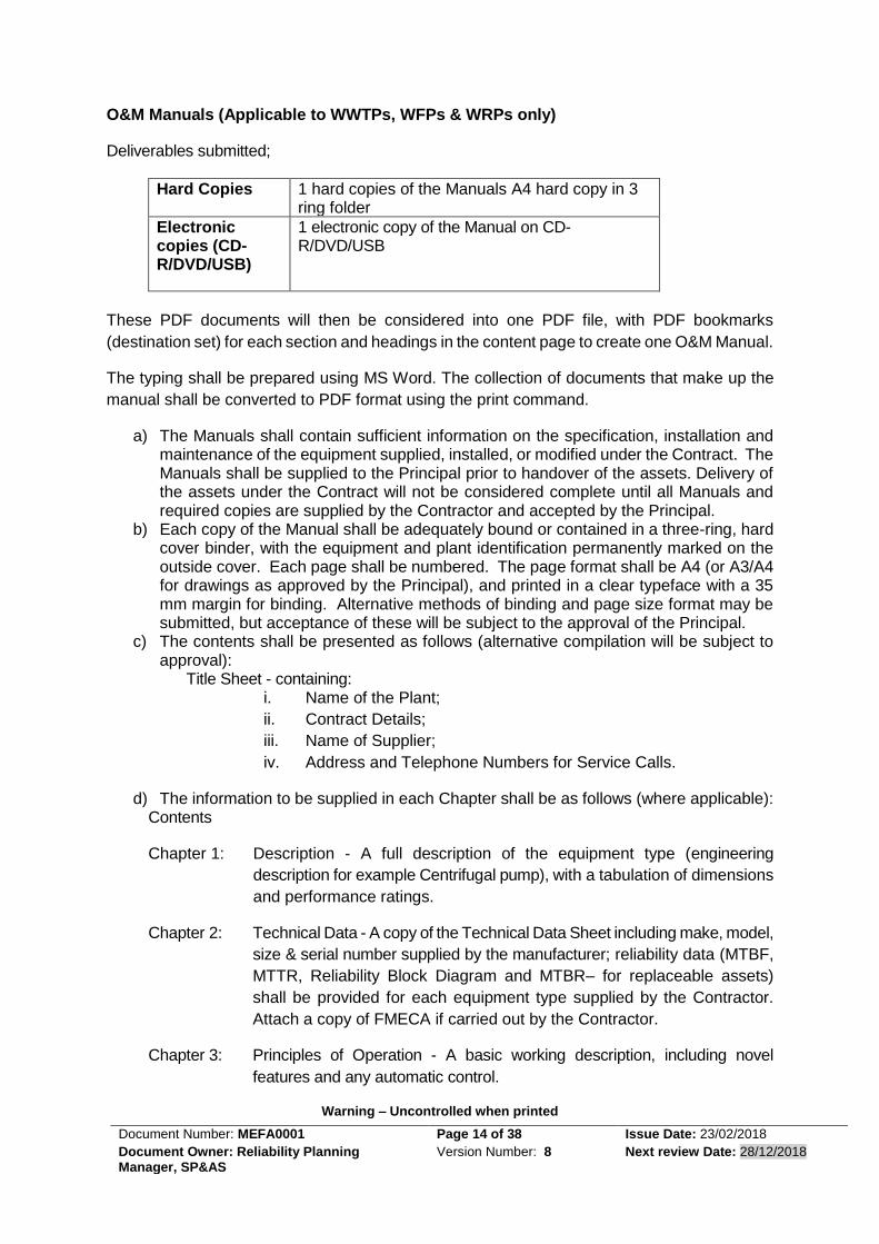
O&M Manuals (Applicable to WWTPs, WFPs & WRPs only)
Deliverables submitted;
Hard Copies 1 hard copies of the Manuals A4 hard copy in 3 ring folder
Electronic copies (CD-R/DVD/USB)
1 electronic copy of the Manual on CD-R/DVD/USB
These PDF documents will then be considered into one PDF file, with PDF bookmarks
(destination set) for each section and headings in the content page to create one O&M Manual.
The typing shall be prepared using MS Word. The collection of documents that make up the
manual shall be converted to PDF format using the print command.
a) The Manuals shall contain sufficient information on the specification, installation and maintenance of the equipment supplied, installed, or modified under the Contract. The Manuals shall be supplied to the Principal prior to handover of the assets. Delivery of the assets under the Contract will not be considered complete until all Manuals and required copies are supplied by the Contractor and accepted by the Principal.
b) Each copy of the Manual shall be adequately bound or contained in a three-ring, hard cover binder, with the equipment and plant identification permanently marked on the outside cover. Each page shall be numbered. The page format shall be A4 (or A3/A4 for drawings as approved by the Principal), and printed in a clear typeface with a 35 mm margin for binding. Alternative methods of binding and page size format may be submitted, but acceptance of these will be subject to the approval of the Principal.
c) The contents shall be presented as follows (alternative compilation will be subject to approval):
Title Sheet - containing: i. Name of the Plant;
ii. Contract Details;
iii. Name of Supplier;
iv. Address and Telephone Numbers for Service Calls.
d) The information to be supplied in each Chapter shall be as follows (where applicable): Contents
Chapter 1: Description - A full description of the equipment type (engineering
description for example Centrifugal pump), with a tabulation of dimensions
and performance ratings.
Chapter 2: Technical Data - A copy of the Technical Data Sheet including make, model,
size & serial number supplied by the manufacturer; reliability data (MTBF,
MTTR, Reliability Block Diagram and MTBR– for replaceable assets)
shall be provided for each equipment type supplied by the Contractor.
Attach a copy of FMECA if carried out by the Contractor.
Chapter 3: Principles of Operation - A basic working description, including novel
features and any automatic control.

Warning – Uncontrolled when printed
Document Number: MEFA0001 Page 15 of 38 Issue Date: 23/02/2018
Document Owner: Reliability Planning Manager, SP&AS
Version Number: 8 Next review Date: 28/12/2018
Chapter 4: Operating Instructions - A step-by-step procedure organised into sections
entitled:
4.4.1.1.1.1 Checks before Starting; 4.4.1.1.1.2 Starting; 4.4.1.1.1.3 Continuous Operation; 4.4.1.1.1.4 Stopping; 4.4.1.1.1.5 Emergency Stopping; 4.4.1.1.1.6 Abnormal Operation as applicable.
Chapter 5: Installation and Commissioning Instructions - Details of Standards and
procedures for mounting or erecting, wiring and lubricating the
equipment. The commissioning instructions shall include step-by-step
procedures for checks before the first start, first start, after starting and
operational tests. They should be co-ordinated with Chapters 3 and 8
and may refer to both.
Chapter 6 Maintenance Plans (Preventive Maintenance) Step-by-step procedure for
preventative maintenance work to be carried out at various intervals,
supported by FMECA, if available. (eg. two weeks, four weeks, six weeks
etc;) Procedure should also clearly indicate replacements of
consumables where necessary and the labour-hours required for each
activity.
Chapter 7: Maintenance Plans (Overhaul / Major Periodic Maintenance) Step-by-
step procedures for fault finding and correction and for overhauling (major
periodic maintenance) involving parts other than consumables. A list of
necessary special tools should be included. Indicate Design Life.
Chapter 8: Test Data, Inspection Results (eg Test Sheets, FAT, SAT etc) and
Troubleshooting -– Instructions to qualified tradesman for assessing the
operational performance of the equipment and system.
Chapter 9: Parts List and Recommended Spares - Illustrations and schedules for
identification and specifications for all items in the equipment. Exploded
diagrams are required, if available. The recommended spare parts stock
must be indicated.
Appendices
Notes:
The information in Chapters 1 to 5 must be included for each item supplied, while the extent
of information in Chapters 6 to 9 may vary with the complexity of the equipment. The text shall
be in English and easily understood by plant operators and fitters. Information irrelevant to
the equipment supplied in the Contract shall not be included in the Manual.
The PDF Version of the manual shall have bookmarks for each chapter with major headings.
The bookmark shall include the reference number and description. Documents that are locked

Warning – Uncontrolled when printed
Document Number: MEFA0001 Page 16 of 38 Issue Date: 23/02/2018
Document Owner: Reliability Planning Manager, SP&AS
Version Number: 8 Next review Date: 28/12/2018
and cannot be included into a single PDF document shall be scanned at 250dpi, saved as
jpeg with maximum compression. This document shall then be included into the single PDF
document. When converting documents to PDF use the print command and select the PDF
printer. This will automatically create the “Bookmarks” while converting other formatted
documents to PDF. When collating various documents into a single PDF document use the
Acrobat “Combine Files into PDF Command”.
Advertising brochures and catalogues are not acceptable. Remove all pages not associated
with the equipment installed.
All electronic files should be in “Vector” format (not scanned) if possible. Some signed
documents will need to be in “Raster”. Documents in “Raster” that are available in “vector”
format are not locked for collating and will be rejected.
Equipment such as cable connectors, lamp holders, non-repairable equipment or items that
are readily available at the local electrical equipment supplier, are not required in the O&M
Manual.
6.2 O&M Manuals (Applicable to all facilities other than WWTPs, WFPs &
WRPs) Deliverables submitted:
Hard Copies 1 hard copies of the Manuals in A4 with 3 ring
folder
Electronic copies (CD-R/DVD/USB)
1 electronic copy of the Manual on CD-R/DVD/USB using MS Word (preferred)
When a combination of different software is used or where there are several components /
pages of PDF documents forming one O & M Manual, the document shall be consolidated into
one PDF file, with bookmarks for each section in the content page. PDF Version of the manual
shall have bookmarks for each chapter and each major heading. The bookmark shall include
the reference number and description. All electronic files should be in “Vector” format (not
scanned) if possible. Operation and Maintenance instructions that are of a general nature are
not acceptable.
Documents that are locked and cannot be included into a single PDF document shall be
scanned at 250dpi, saved as jpeg with maximum compression. This document shall then be
included into the single PDF document.
Advertising brochures and catalogues are not acceptable. All pages not associated with the
equipment installed will be removed.
Operation and maintenance information for each of the following asset types shall be included
in the O&M Manual. O&M Manuals shall also be supplied for any additional asset, if it is
specified.

Warning – Uncontrolled when printed
Document Number: MEFA0001 Page 17 of 38 Issue Date: 23/02/2018
Document Owner: Reliability Planning Manager, SP&AS
Version Number: 8 Next review Date: 28/12/2018
• Operation and maintenance of the pumping station.
• Pump and motor
• Control equipment
• Specialised equipment
• Odour Control Unit
• Chemical Dosing Unit
• Power Generating Equipment
• Cranes and Hoists
• Ventilation systems Ensure that the O&M Manual specifies the assets that are installed and used within the
facility ONLY, do not include manufactures specifications for all equipment’s with the
company’s product list as this will be rejected by the Principal.
Chemical Dosing and Odour Control units shall be treated as standalone and the O&M manual
for them will be separate to the one supplied for the pumping station.
The contents of the O&M Manual shall be in accordance with 6.1 a), b) and c) above.
6.3 Manufacturer’s Instructions Manuals The Contractor shall supply manufacturer’s instruction manuals if available for each asset
installed or key component of an asset. Examples of key components include PLCs, Motors,
Gear boxes etc. Items such as connectors, lamp holders and contactors are not regarded as
key assets or key components.
The manufacturer’s instruction manuals shall be included as appendices to the relevant O&M
manual. Refer to Clause 6.1 d) on how to produce a consolidated O & M Manual.
7 Testing and Commissioning
7.1 General Commissioning is the process of firstly checking the performance of individual elements of the
new works and then the checking and tuning of the system as a whole in order to bring the
works into service.
Commissioning should proceed in accordance with the Contractor’s “Testing and
Commissioning Plan” that has been reviewed and approved by the Principal. During the
process of review of the Commissioning Plan, the Principal will nominate the inspections and
tests that will be witnessed by the Principal. This will allow all parties to be aware of the
proposed transition methodology, where applicable.
The Contractor shall be responsible for the commissioning of the entire works. The Contractor
shall be responsible to test, calibrate and fine-tune all instrumentation, protective devices and
all field equipment to put the whole works into automatic operation. The commissioning of the
plant shall include all possible modes of operation including emergency situations such as
power failures, control failures etc.
Warning – Uncontrolled when printed
Document Number: MEFA0001 Page 18 of 38 Issue Date: 23/02/2018
Document Owner: Reliability Planning Manager, SP&AS
Version Number: 8 Next review Date: 28/12/2018
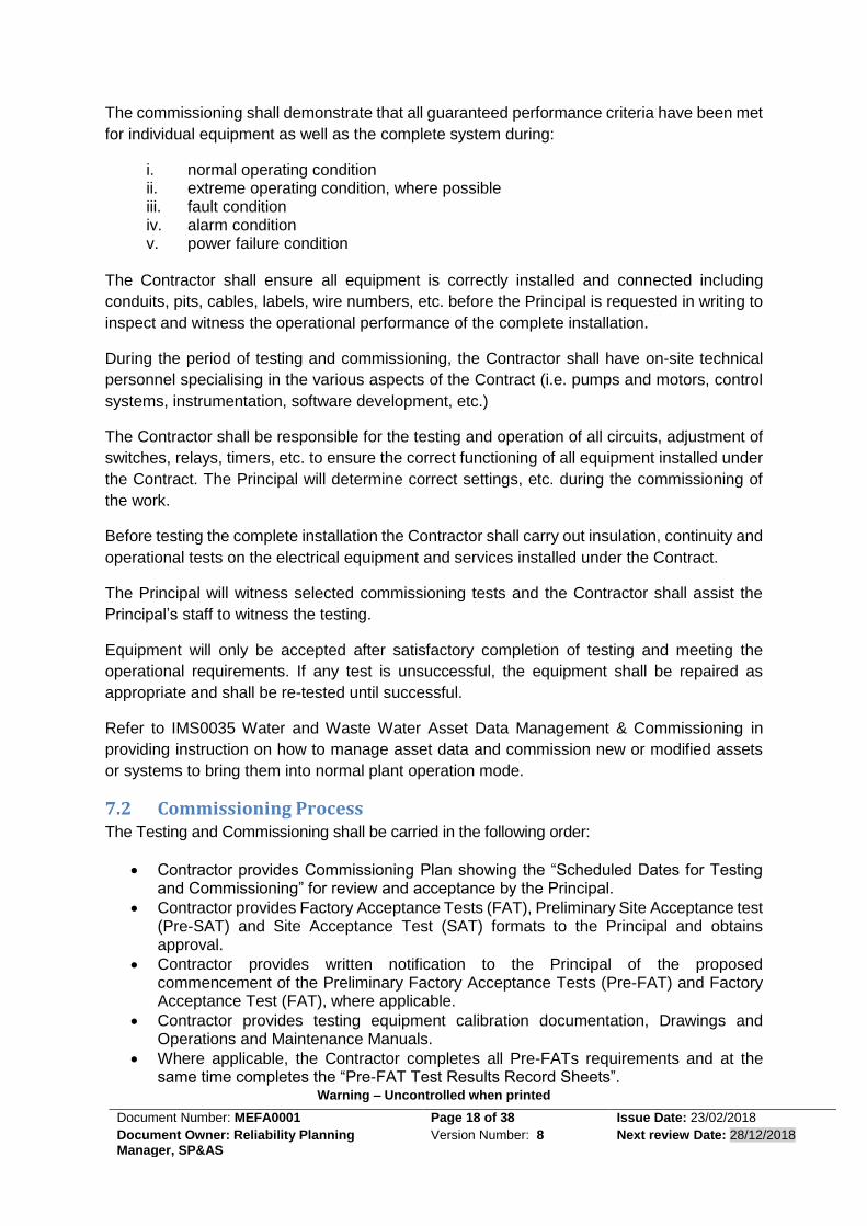
The commissioning shall demonstrate that all guaranteed performance criteria have been met
for individual equipment as well as the complete system during:
i. normal operating condition ii. extreme operating condition, where possible iii. fault condition iv. alarm condition v. power failure condition
The Contractor shall ensure all equipment is correctly installed and connected including
conduits, pits, cables, labels, wire numbers, etc. before the Principal is requested in writing to
inspect and witness the operational performance of the complete installation.
During the period of testing and commissioning, the Contractor shall have on-site technical
personnel specialising in the various aspects of the Contract (i.e. pumps and motors, control
systems, instrumentation, software development, etc.)
The Contractor shall be responsible for the testing and operation of all circuits, adjustment of
switches, relays, timers, etc. to ensure the correct functioning of all equipment installed under
the Contract. The Principal will determine correct settings, etc. during the commissioning of
the work.
Before testing the complete installation the Contractor shall carry out insulation, continuity and
operational tests on the electrical equipment and services installed under the Contract.
The Principal will witness selected commissioning tests and the Contractor shall assist the
Principal’s staff to witness the testing.
Equipment will only be accepted after satisfactory completion of testing and meeting the
operational requirements. If any test is unsuccessful, the equipment shall be repaired as
appropriate and shall be re-tested until successful.
Refer to IMS0035 Water and Waste Water Asset Data Management & Commissioning in
providing instruction on how to manage asset data and commission new or modified assets
or systems to bring them into normal plant operation mode.
7.2 Commissioning Process The Testing and Commissioning shall be carried in the following order:
• Contractor provides Commissioning Plan showing the “Scheduled Dates for Testing and Commissioning” for review and acceptance by the Principal.
• Contractor provides Factory Acceptance Tests (FAT), Preliminary Site Acceptance test (Pre-SAT) and Site Acceptance Test (SAT) formats to the Principal and obtains approval.
• Contractor provides written notification to the Principal of the proposed commencement of the Preliminary Factory Acceptance Tests (Pre-FAT) and Factory Acceptance Test (FAT), where applicable.
• Contractor provides testing equipment calibration documentation, Drawings and Operations and Maintenance Manuals.
• Where applicable, the Contractor completes all Pre-FATs requirements and at the same time completes the “Pre-FAT Test Results Record Sheets”.

Warning – Uncontrolled when printed
Document Number: MEFA0001 Page 19 of 38 Issue Date: 23/02/2018
Document Owner: Reliability Planning Manager, SP&AS
Version Number: 8 Next review Date: 28/12/2018
• Contactor completes FAT and submits the completed “Pre-FAT Test Results Record Sheets” and “FAT Test Results Record Sheets” to the Principal.
• The Contractor delivers and installs the equipment on site after the Principal has accepted the Pre-FAT and FAT results and has approved the delivery and installation.
• Contractor provides written notification to the Principal of the proposed commencement of the Pre-SAT and SAT.
• Contractor provides updated Drawings and Operations and Maintenance Manuals.
• Contractor arranges and meets with the Principal at least 5 working days prior to Pre-SAT and SAT. At the meeting the proposed commissioning methodology and site-specific issues including Operator and Maintainer training plans shall be discussed.
• Contractor completes all Pre-SATs and the “Pre SAT Test Results Record Sheets” and submits the “Pre-SAT Test Results Record Sheets”. The Principal will advise the Contractor of the acceptance or otherwise of the Pre-SAT results.
• Contractor provides all relevant information and confirms date for the SAT.
• Contractor completes all SAT and submits the “SAT Test Results Record Sheets”. The Principal will advise the Contractor of the acceptance or otherwise of the SAT results.
• Contractor modifies the FMECA carried out at Design Stage by incorporating all the as built assets. (Only required when as built assets differ from those in the original design)
• Operator and maintainer training plan and obtained acceptance from the Principal.
• Contractor handover of final Operations and Maintenance Manual, Work-As-Constructed Drawings and any other documentation to Principal, after submission of test results.
• Contractor carries out Operator and Maintainer training.
7.3 Commissioning Plan and Testing The Contractor shall be responsible for arranging and conducting all tests to demonstrate
compliance with the requirements of the Contract.
The Designer shall prepare a “Commissioning Plan” (Prepared by Designer-see clause 1.2.2
Commissioning Plan) to cover all aspects of factory testing, site testing, Operator and
Maintainer training and commissioning. The “Commissioning Plan” may be of any format to
suit the Contractor. Where a Commissioning Plan has been prepared under Clause 1.2.2, the
Contractor shall amplify on the original plans and ITPs to comply with this Clause. It shall
include detailed testing procedures, commissioning procedures and test check sheets. Site
tests shall include testing of the equipment supplied under the Contract under all operating
modes and shall fully test all equipment, systems, controls and procedures supplied,
developed or installed as part of the Contract. The commissioning trials shall demonstrate that
all sections of the work are fully operational and that the guaranteed performance criteria have
been met.
The “Commissioning Plan” shall be given to, and fully discussed with, the Principal at least 20
working days before testing is due to commence. The program and schedule of tests may
require modification to integrate with other elements of the Principal’s system.
With the submission of the “Commissioning Plan” under this clause, the Contractor shall
include the proposed Acceptance Criteria for all tests and commissioning and undertake a
review of the criteria with the Principal.
After agreement with the Principal, the Contractor shall provide two sets of detailed testing,
pre-commissioning and commissioning instructions together with an agreed program.

Warning – Uncontrolled when printed
Document Number: MEFA0001 Page 20 of 38 Issue Date: 23/02/2018
Document Owner: Reliability Planning Manager, SP&AS
Version Number: 8 Next review Date: 28/12/2018
Testing shall consist of four formal tests:
• Preliminary Factory Acceptance Tests (Pre-FAT) supplied by the Contractor
• Factory Acceptance Test (FAT) supplied by the Contractor,
• Preliminary Site Acceptance Tests (Pre-SAT) supplied by the Principal (Pre SAT forms) and
• Site Acceptance Test (SAT) supplied by the Principal (SAT forms).
The Principal shall be notified 10 working days before each of these test are to commence so
that the Principal can be present to witness the testing.
The Contractor shall provide all expertise, labour, materials and test equipment required for
testing and commissioning. All test equipment shall have been checked for calibration prior
to tests. Calibration documentation shall be made available for Principal’s inspection.
The Contractor shall have available a complete set of spare parts for minor items, such as,
relays, lamps, contractor coils, etc. so that the testing process is not delayed due to the failure
of such items.
The Principal shall have the right to witness any tests and inspect any equipment at any stage
of the Contract to confirm progress and conformance. This may involve re-testing if considered
warranted by the Principal. This shall not relieve the Contractor of any responsibility to ensure
proper operation.
7.4 Scheduled Dates for Testing and Commissioning The Contractor shall submit a “Scheduled Dates for Testing and Commissioning” and provide
updates to the Commissioning Plan when changes occur.
The plan shall allow sufficient time for testing (including Pre-FAT and Pre-SAT), and if
necessary re-testing of equipment and fit in with the overall project completion time. The plan
shall take into consideration the Contractor’s experience obtained from previous sites of a
similar type and complexity. The Principal may defer the scheduled dates if the Contractor is
considered not sufficiently well prepared for the tests.
The Commissioning Plan shall show commencement and completion date and times and the
number of personnel present for the FAT and the SAT.
When scheduled dates for commissioning and testing are cancelled or not utilised as planned
by the Contractor, the Contractor shall pay to the Principal all costs due to the non-utilisation
(as programmed) of the scheduled dates. These costs will include:
• the cost of arranging the cancellation and/or alteration;
• the cost of the cancellation and/or non-utilisation;
• the cost of arranging a substitute scheduled date and
• any other costs associated with the cancellation and/or non-utilisation.

Warning – Uncontrolled when printed
Document Number: MEFA0001 Page 21 of 38 Issue Date: 23/02/2018
Document Owner: Reliability Planning Manager, SP&AS
Version Number: 8 Next review Date: 28/12/2018
As the cost of cancellation varies dependent upon the amount of notification of the cancellation the costs vary commensurately.
7.5 Testing
7.5.1 Pre- Factory Acceptance Testing (for electrical equipment)
A Pre-FAT shall be carried out when:
• manufacturing is complete;
• the system or sub-system is fully assembled;
• the assembly is ready for transportation to site and
• calibration sheets are complete and available. The Pre-FAT shall be carried out at the manufacturer’s works by the Contractor and prior to a
FAT. This is intended to check the scope of work and minimise the amount of time required to
complete the FAT by eliminating wiring, labelling, workmanship and equipment functionality
problems. Some Pre-FATs may be repeated during the FAT to verify correctness of the
results. The Contractor shall supply the “Pre-FAT Test Result Record Sheets” and they shall
detail all tests required during Pre-FAT.
The Principal will not normally witness the Pre-FAT, however, but shall have the right to do
so.
The copies of the “Pre-FAT Test Results Record Sheets” shall be submitted prior to
commencement of the FAT for approval. Each test shall be dated and signed off by two
representative of the Contractor.
The Pre-FATs shall itemise and cover all tests associated with the following:
• completeness of work;
• labelling and wiring;
• all work complies with relevant standards and workmanship;
• compliance with the IICATS I&C Standards Manual;
• correctness of drawing/equipment;
• equipment rating, eg. circuit breakers, etc.;
• firmness of equipment and
• set overloads, soft starter / variable speed parameters; Note the Contractor shall supply a full set of variable speed parameters in a spreadsheet including a listing of all those that have been left untouched and left as factory set (for future reference, Also any software and tools required to alter the VSDs.
• Functional operations of switches, circuit breakers, push buttons, drives, PLC / RTU inputs and outputs etc.
7.5.2 Factory Acceptance Testing
As a minimum, all electrical panels, cabinets and kiosks shall be factory inspected and tested (FAT). Other equipment that requires factory acceptance testing along with the type of test maybe specified in the contract, needs specification or concept design document.
7.5.2.1 General
A FAT shall be carried out when:
• All Pre-FAT’s have been successfully completed;

Warning – Uncontrolled when printed
Document Number: MEFA0001 Page 22 of 38 Issue Date: 23/02/2018
Document Owner: Reliability Planning Manager, SP&AS
Version Number: 8 Next review Date: 28/12/2018
• Operation and maintenance manuals are complete;
• An updated set of all drawings are available; The “Pre-FAT Test Results Record Sheets” are completed and recorded by the Contractor.
The FAT shall be carried out at the manufacturer’s works.
At least 10 days’ notice or 90 days (for international attendance) shall be given for a proposed
FAT. The Contractor shall complete all test detailed on the “FAT Test Result Record Sheets”.
Each test shall be dated and signed off by the Contractor.
During the FAT the Principal may issue Non Conformance Reports (NCR)/ Action Requests
(AR). These will indicate that equipment or the procedure does not conform to the Contract or
relevant standard. In this case, the Contractor shall modify and re-test the system. This
process shall be repeated until the test is successful. The Principal shall determine whether
re-testing can be carried out as part of the current FAT or re-scheduled to another date. The
Contractor shall sign all NCR/AR.
At the conclusion of the FAT and after all NCR/AR are cleared and approval given by the
Principal, the equipment shall be delivered and installed on site.
7.5.2.2 Hydrostatic Testing of Pumps
All pump casings, after machining, shall be subject to a hydrostatic test at the manufacturer’s
works by the Contractor. Alternatively, the hydrostatic tests may be carried out after the pump
has been assembled.
The total test pressure shall be 1.5 times the sum of pump maximum shut off head and
maximum suction head. The use of long bolts or other similar apparatus extending through
the pump casing to seal off the suction, discharge, shaft or other openings during the test shall
not be permitted.
The pressure shall be sustained for at least two hours. During the hydrostatic test, there shall
be no visible leakage through the shaft seals or any other part of the casing. The exterior of
the casing shall remain completely dry and there shall be no visible deformation or distortion
of the casing or other pump components.
The Contractor shall replace all casing or parts found defective or unsound in any respect
under this test at no cost to the Principal.
7.5.2.3 Performance Testing of Pumps
Pumps shall be witness works performance tested with their respective motors and starters
(or variable speed drives, if supplied) at the manufacturer’s /works by the Contractor in
accordance with AS 2417 – 2001: “Rotodynamic pumps – Hydraulic performance acceptance
tests – Grades 1 and 2”. Grade 1 tolerance factors shall be adopted for pumps driven by
motors 50kW or larger, and Grade 2 for pumps with motors smaller than 50kW. The
Manufacturer / Contractor shall provide all materials, equipment (including test starters if not
supplied with the pumps) and labour for the works tests.
Unless stated otherwise, the performance tests shall include pump capacity (Q), head (H), net
positive suction head required (NPSHr) and overall efficiency (O/A). The overall efficiency

Warning – Uncontrolled when printed
Document Number: MEFA0001 Page 23 of 38 Issue Date: 23/02/2018
Document Owner: Reliability Planning Manager, SP&AS
Version Number: 8 Next review Date: 28/12/2018
guarantee shall include pump, motor and starter or, if supplied, variable speed drive losses.
Acceptance of NSPHr tests shall be based on satisfying the stated NPSHr at 3% head drop,
i.e. “NPSH3”, at the pump minimum head / maximum flow duty point. The NPSHr tests will
include a minimum of three tests, ie one at this duty point and one on either side of it, to confirm
the trending of the NPSHr curve.
7.5.2.4 Performance Testing- Factory, General (applicable to all assets including pumps)
The tests carried out at the manufacturer’s works shall form the basis of the Factory
Acceptance Tests for assets / equipment supplied under the Contract. Test certificates and
performance curves shall be provided for each test.
Should any defect show up or develop, or the capacity, efficiency or net positive suction head
required fall short of that guaranteed, the Contractor shall, within a reasonable period, make
good such defects at his own expense. If the Contractor does not carry out the necessary
corrective work, the Principal may reject the complete unit or reduce the payment. If the unit
is rejected, the Contractor shall refund any payments already made.
7.5.2.5 Bearing Tests
In conjunction with the performance tests, the Contractor shall continuously record bearing
housings temperatures while operating at the most adversely loading conditions. The test
should be conducted for a minimum of four hours and until the temperatures have peaked and
stabilised relative to the ambient temperature for a period of at least one hour. The bearing
housings temperatures, after adjustment for an ambient temperature of 45oC, shall not exceed
the maximum bearing temperature stated by the equipment manufacturers. These tests shall
be repeated on site for final acceptance.
7.5.2.6 Vibration Tests
Preliminary vibration tests are to be undertaken at the manufacturer’s works during
performance tests and repeated on site for final acceptance. The vibration tests shall be
conducted and evaluated in accordance with the relevant Australian Standard.
7.5.2.7 Noise Tests
Preliminary noise tests shall also be undertaken at the manufacturer’s works during
performance tests and repeated on site for final acceptance. The preliminary noise tests shall
identify any obvious noisy operating condition within the asset / equipment operating range.
The obtained data are to be evaluated and translated to defined site noise performance
conditions. The equipment shall only be delivered to site if the above evaluation indicates that
the specified site noise levels will be achieved.
7.5.2.8 Testing of Valves, Pipes and Fittings
All valves, pipes and fittings shall be subject to hydrostatic and leakage acceptance tests and
all other production and batch release tests as specified in the relevant standards at the
manufacturer’s works. The valves shall also be supplied with Type Test Certificates. The tests
shall be carried out in accordance with relevant Australian Standards.

Warning – Uncontrolled when printed
Document Number: MEFA0001 Page 24 of 38 Issue Date: 23/02/2018
Document Owner: Reliability Planning Manager, SP&AS
Version Number: 8 Next review Date: 28/12/2018
7.5.2.9 Testing of Electrical Control Equipment
The FAT shall be a fully simulated test of all operating hardwired functions. External equipment
shall be connected to simulate actual field devices, eg switches, signal generators, etc. The
FAT shall cover as much of the hardwired operational system of the site as practicable.
Where applicable, the Contractor shall download a test program, provided by the Principal, to
the RTU and PLC. The Contractor shall use these programs to test the integrity of the RTU
and PLC. This is part of the FAT and the results shall be recorded on the “FAT Test Results
Record Sheets”. The Principal will free issue the PLC / RTU programming software for use on
this Contract, where applicable. The Contractor shall purchase the PLC / RTU hardware, PC
or laptop and PLC programming software.
Where applicable, RTU may be supplied by the Principal. If the RTU supplied by the Principal
is found to be faulty the Contractor shall record the nature of the failure and notify the Principal.
The Contractor shall return the RTU to the Principal. The Principal will then provide a new
RTU. Tests shall be repeated when a replacement RTU is installed.
Any drawing changes resulting from the FAT shall be recorded and incorporated into the next
drawing issue. The copies of the “FAT Test Results Record Sheets” shall be submitted for
approval at the conclusion of the FAT.
The FATs shall itemise and perform all tests associated with the installed assets and shall
include the following:
• continuity tests;
• insulation test;
• 24 V DC output;
• three phase power up tests;
• hardwired status indication, control, interlocks and logic functions;
• RTU/PLC digital and analogue signals for all I/Os;
• Soft starter / variable speed drive checks in manual operation and parameter setting;
• GPO, panel light and panel cooling fans;
• simulate and check all analogue signals indicators and generation;
• noise test;
• instrument test to prove calibration, accuracy, repeatability, hysteresis checks, etc.;
• analogue loop tests;
• running the RTU/PLC test program. This shall include testing digital inputs/outputs, analogue inputs/outputs and the five communication ports on the RTU and
• point to point operations test.
7.5.2.10 Testing of Electrical Switchboards
The following requirements apply for the power supply/main distribution board, motor starters
etc.
a) The switchgear shall be tested in accordance with the requirements of the appropriate Australian Standards and as required by authorities having jurisdiction, such as the Supply Authority.
b) As a minimum, tests shall include: i. insulation resistance, ii. power frequency voltage withstand,

Warning – Uncontrolled when printed
Document Number: MEFA0001 Page 25 of 38 Issue Date: 23/02/2018
Document Owner: Reliability Planning Manager, SP&AS
Version Number: 8 Next review Date: 28/12/2018
iii. resistance of primary circuits and earthing circuits, including busbars, switching devices and earthing switches,
iv. verification of correct wiring, v. mechanical operation of all switch devices and interlocks, vi. verification of instrument and control transformer ratios, polarities and
connections, vii. magnetising curves of current transformers, viii. measurement of partial discharges of CTs and VTs, ix. functional tests of control and protection circuits, including tests at the
stated limits of control and auxiliary supply voltages, x. accuracy check of meters and transducers, at 25%, 50%, 75% and 100%
of full scale, minimum, xi. performance checks of protection relays at a minimum of four points on the
operating curve, including pick-up, xii. verification of correct functioning of all ancillary devices and equipment
such as slow-close levers, manual spring charging devices, test leads, earthing equipment, wear gauges.
c) Primary injection shall be used to verify the correct polarity and ratio of each protection current transformer and the operation of the associated protective relay(s) for at least one current. Testing for verifying the protective relays’ calibrations at other currents shall be secondary injection testing.
d) Primary injection tests shall be performed on each metering current transformer and its associated meter(s) or transducer(s). As a minimum, these tests shall be performed at one half and at full-scale values.
Note: If, due to limitations of test equipment, a phase-controlled 3-phase current test source is not readily available, 3-phase meters and transducers may be tested using single-phase current sources.
7.5.2.11 Testing of Electrical Motors
Each motor shall be routine tested strictly in accordance with AS1359.101 and any subsequent amendments.
7.5.3 Pre Site Acceptance Testing
This clause is applicable to all assets / equipment procured under the Contract, as per the Forms supplied by the Principal.
7.5.3.1 General
Pre-SAT is the activity of verifying the individual components of the assets meet their
specification and performance requirements in preparation of plant and equipment for Site
Acceptance Tasting and subsequent operation.
Pre-SAT shall be conducted in a logical sequence in accordance with the approved
Commissioning Plan.
A Pre-SAT shall be carried out when:
• all equipment has been installed and ready for dry / wet testing;
• point to point wiring checks completed;
• the new switchboard has been connected to the power supply (if feasible);
• all new equipment, that will not interfere with the operation of existing equipment, has been connected;

Warning – Uncontrolled when printed
Document Number: MEFA0001 Page 26 of 38 Issue Date: 23/02/2018
Document Owner: Reliability Planning Manager, SP&AS
Version Number: 8 Next review Date: 28/12/2018
• the site is ready for disconnection of the old equipment and connection of the remaining new equipment;
• all preparation work and notifications are complete;
• the new RTU is connected to the communication network via the MDF and is ready to be connected to IICATS and put into operation. This will require the communications service provider to terminate and connect the lead-in cable (if feasible);
• all documentation has been provided and available on site;
• calibration sheets are complete and available on site and
• SCADA programming & I/O testing has been completed. The Pre-SAT is intended to minimise the amount of time required to complete the SAT by checking the scope of works and preliminary testing of wiring and eliminating workmanship or equipment functional problems. The Principal will witness the activities nominated in the Commissioning Plan and any other
activities deemed necessary.
The “Pre-SAT Test Result Record Sheets” will detail all checks and tests required during Pre-
SAT. The Contractor shall complete these sheets during Pre-SAT and submit to the Principal
at the completion of the Pre-SAT for approval. Each test shall be dated and signed off by the
Contractor and the Principal.
The copies of the completed “Pre-SAT Test Results Record Sheets” shall be submitted at the conclusion of the Pre-SAT. The Pre-SAT’s shall itemise and cover all tests associated with the following:
• completeness of installation work / part of installation;
• conformance and performance testing of equipment to specification;
• protective coatings and repair work when necessary;
• pressure testing of pipe work;
• noise tests;
• electrical continuity;
• dry run functional tests;
• wet-run functional tests;
• simulated fault condition tests;
• equipment is correctly labeled;
• direction of rotation of rotating equipment;
• clearance end play and operation of major bearings;
• set and calibrate protection devices, instruments, safety interlocks, emergency stops, field equipment etc;
• alignment of drive systems;
• control System of PLC / RTU logic test and
• performance testing
7.5.2.2 Power and IICATS/SCADA Tests
The following tests shall be carried out during the Pre-SAT stage:
The Contractor shall re-test some items that have been tested during the FAT. This will provide
a confidence check to establish assurance that critical components are still operational and

Warning – Uncontrolled when printed
Document Number: MEFA0001 Page 27 of 38 Issue Date: 23/02/2018
Document Owner: Reliability Planning Manager, SP&AS
Version Number: 8 Next review Date: 28/12/2018
that equipment operation has not been altered during transport. All of these FAT tests shall
be repeated on all the sites.
The Principal will carry out IICATS Telemetry and picture testing. The IICATS site-
commissioning engineer will be in verbal contact (mobile phone) with a remote IICATS
workstation operator (IICATS Commissioning Technical Support Officer) during these tests.
The Contractor shall assist and make allowance for this time in his schedule and necessary
modifications to the RTU/PLC software.
7.5.2.3 Pipework Hydrostatic Tests
No work shall be backfilled, covered or concealed until it has been inspected and tested. Pipe
joints and structures shall be exposed to enable observation during hydrostatic tests.
Pipelines shall be tested for leakage and defects in the pipes, joints, fittings, valves and thrust
blocks. The test shall be carried out in sections as soon as practicable after each section has
been laid, jointed and cleaned and not earlier than seven days after the last concrete thrust
block in the section has been cast unless suitable strutting and bracing is installed to take the
thrust. Solvent cement joints shall be cured for at least 24 hours before testing.
In order to achieve stable testing conditions, the pipe section to be tested shall be filled slowly
with water, ensuring all air is expelled and allowing for absorption. The section shall be kept
full of water for 24 hours prior to the commencement of the pressure testing. During pressure
testing of a pipeline each isolation valve shall sustain the full pressure on one side of the valve
with no pressure on the other side.
The Contractor must ensure that all pipe components under test (including thrust blocks) have
rated pressure or manufacturers recommended maximum test pressure above the hydrostatic
test pressure. The test report is to be supplied to the Principal.
Any defects found during the hydrostatic testing shall be repaired by the Contractor at his own
cost and the test repeated until the Principal is satisfied that the whole work is watertight and
sound.
Pipework shall be tested in accordance with relevant Australian Standards. The test pressure
for all pipework shall be the design pressure plus 25%. The design pressure for pumping
station discharge pipework and pressure mains shall be the larger of the pump shut-off head
plus the maximum head at pump suction and the maximum pressure determined by water
hammer analysis. For all other pipework the design pressure shall be the larger of the
maximum head and the maximum pressure determined by water hammer analysis.
The pipe work shall be deemed tested when the test pressure has been maintained for two
hours without topping up and there is no visible leakage or sweating or pressure drop. Test
certificates are to be supplied by the Contractor.
7.5.2.4 Pump Performance Tests – On site
After completing the individual equipment tests at the site, the Contractor shall test each
pumping unit in the manual mode of operation. Only after individual pumping units are proved
to be operating satisfactorily in the manual mode shall the pumping unit be allowed to be
tested in other modes of operation. Prior to IICATS/SCADA operated testing, the Contractor

Warning – Uncontrolled when printed
Document Number: MEFA0001 Page 28 of 38 Issue Date: 23/02/2018
Document Owner: Reliability Planning Manager, SP&AS
Version Number: 8 Next review Date: 28/12/2018
shall have calibrated all equipment, including starters, VSDs, operating level sensors and
protective devices. The testing shall include the checking of all the signals that are required to
be sent to the IICATS/SCADA System.
The Contractor is required to carry out performance testing of the pumps installed under the
Contract to verify that each unit, running at the stated speed and operating against the stated
head, provides a continuous net output which is not less than the output specified in the
Contract. Details of these pump performance tests are to be incorporated in the final pumping
station O&M Manuals.
The site tests shall confirm that the pumps in situ performances agree with the works tests
and guarantees. Unless stated otherwise, the test shall include pump capacity (Q), head (H),
overall efficiency (O/A), noise and vibration. In case of any major discrepancy the Contractor
shall investigate the reasons and make every effort to rectify the defect within a reasonable
period and at his own expense.
The site pump performance tests shall include bearing temperature rise and vibration tests.
The tests shall also be conducted for the most adversely loading conditions.
The Principal reserves the right to carry out on-site tests jointly with the Contractor.
7.5.2.5 Crane Tests
Cranes shall be tested and commissioned in accordance with AS1418.3. Prior to the testing,
the crane shall be inspected in accordance with AS 1418.1. Following testing a Work Cover
Certificate will have to be obtained for the lifting device and provided to the Principal.
7.5.2.6 Noise Tests
The Contractor shall conduct noise tests on all individual equipment installed and the complete
plant carried out under full operational load. The noise tests shall be conducted under the
noisiest loading conditions within the defined operating range. The sound pressure level shall
be measured with a precision sound level meter conforming to AS1259. All measurements to
be carried out and certified by trained personnel with currently N.A.T.A. calibrated equipment
and shall conform to the requirements of the Contract. The measured data shall be supplied
in Sound Pressure Levels (SPL) and Sound Power Levels (SWL) – refer to table below –
Noise Analysis Data sheet.
The Contractor shall supply full details of the test procedure, conditions and standards used.
The Contractor shall enter the results of the above tests in a “NOISE ANALYSIS, Data Sheet”
which shall be included in the commissioning records.
Noise Analysis – Data sheet
NOISE ANALYSIS – DATA SHEET Description
dB(A) L
Aeq
63 Hz 125 Hz 250Hz 500Hz 1kHz 2kHz 4kHz 8kHz

Warning – Uncontrolled when printed
Document Number: MEFA0001 Page 29 of 38 Issue Date: 23/02/2018
Document Owner: Reliability Planning Manager, SP&AS
Version Number: 8 Next review Date: 28/12/2018
Sound Pressure Levels (SPL) at 1m (or other – specify)*
Sound Power Levels (SWL)
Standard by which noise measured – AS……………………………………. Ambient Noise Levels ………………………………………………………dB(A) Directivity index………………………………………………………………… Test description………………………………………………………………… Test room condition…………………………………………………………… Other information……………………………………………………………….
The test results shall be used to verify compliance with both OH&S and environmental noise
regulations.
Assets / equipment tested to meet the environmental noise requirements should have an
allowance for noise increase with age and wear. This means the maximum acceptable noise
level shall be at least 2 dBa below the legal limit.
Assets will not be accepted unless they meet the specified noise levels. When assets fail to meet
the required noise levels, the contractor shall take necessary actions to remedy the problems to
the satisfaction of the Principal, at no extra cost to the Principal.
7.5.2.7 Vibration Tests
The Contractor shall provide results of site vibration tests on all installed equipment. The
vibration tests shall be carried out over the full operation range and full operational load and
be witnessed by a representative nominated by the Principal. The vibration tests shall be
conducted and evaluated in accordance with relevant Australian Standard applicable to newly
commissioned assets / equipment. All measurements to be carried out and certified by trained
personnel with currently N.A.T.A. calibrated equipment and shall conform to the requirements
of the Contract. The Contractor shall supply full details of the test procedure, conditions and
standards used.
The Contractor shall enter the results of the above tests in a “VIBRATION ANALYSIS, Data
Sheet” which shall be included in the commissioning records.
Note: Onsite vibration testing will not be required for submersible pumps and mixers mounted
in a wet wells, reservoirs, storages and channels etc. unless pump has remote monitoring
points fitted.
7.5.2.8 Site Acceptance Testing
This clause is applicable to all assets / equipment procured under the Contract, as per the
Forms supplied by the Principal.
Site Acceptance Testing is running adjustment of plant and equipment, carrying out all
necessary adjustments and testing to verify the performance under varying operating
conditions. A SAT should be carried out as soon as possible after successful completion of
the Pre-SAT and when:

Warning – Uncontrolled when printed
Document Number: MEFA0001 Page 30 of 38 Issue Date: 23/02/2018
Document Owner: Reliability Planning Manager, SP&AS
Version Number: 8 Next review Date: 28/12/2018
• all possible scope of works is completed;
• no outstanding major NCRs;
• all parties have been notified and are ready;
• all documentation is available for viewing on site including latest drawings, strategy plans, data sheets, test sheets, calibration certificates, supply authority approvals, site access, contingency plan, etc.;
• operation and maintenance manuals are complete;
• an updated set of all drawings are available;
• the “Pre-SAT Test Results Record Sheets” are completed and approved;
• there is a period of dry weather. SAT’s may have to be postponed, if unexpected wet weather occurs and
• approval has been given to carry out the SAT by the Principal.
At least 10 working days’ notice shall be provided for the proposed SAT. This should allow
sufficient time to co-ordinate all relevant parties associated with the SAT. It is expected that a
SAT notification will be provided at the same time as a Pre-SAT notification.
Before agreeing to a SAT the Principal may visit the site to confirm its readiness. The Principal
will witness the SAT. The Contractor shall arrange and meet with the Principal at least 5
working days prior to a proposed SAT to review the proposed commissioning methodology.
Unless the SAT is carried out immediately after the Pre-SAT, the Contractor shall ensure that
critical components are functional, and if required by the Principal, re-test some Pre-SAT
results to verify their correctness. If any fault is found, the Principal shall determine whether
the SAT can commence or be re-scheduled to another date.
During the SAT the Principal may issue Non Conformance Reports (NCR)/ Action Requests
(AR). These will indicate that the equipment does not conform to the Specification or that the
correct procedure has not been followed. The Contractor shall sign all NCR. The Contractor
shall modify and re-test the system if any test is not approved. This process shall be repeated
until the test is successful. The Principal shall determine whether re-testing can be carried out
as part of the current SAT or re-scheduled to another date.
No repairs or modifications shall be carried out unless agreed by all parties. Equipment shall
not be put into operation unless all tests have been completed and approval is obtained from
the Principal.
The Contractor shall supply “SAT Test Result Record Sheets” and complete all tests detailed
on the “SAT Test Result Record Sheets”. Each test shall be dated and signed off by the
Contractor.
The copies of the completed “SAT Test Results Record Sheets” shall be signed off and
submitted for approval at conclusion of the SAT. Any drawing changes resulting from the SAT
shall be recorded and incorporated into the Work as Constructed Drawings. The results of
each test shall be recorded immediately after the test is performed.
Any tests postponed from the Pre-SAT due to lack of mains power or a new communications
line shall be included in the SAT. This includes all tests listed under the Pre-SAT section
“Power and IICATS Tests”. The implications that this will have on the transition time and the

Warning – Uncontrolled when printed
Document Number: MEFA0001 Page 31 of 38 Issue Date: 23/02/2018
Document Owner: Reliability Planning Manager, SP&AS
Version Number: 8 Next review Date: 28/12/2018
addition risk involved in carrying out these tests during the SAT shall be reflected in the
Contractor’s transition strategy.
In addition to any tests carried out at the Pre-SAT stage, the Principal will carry out further
IICATS Telemetry and picture testing.
The SAT’s shall itemise and cover all tests associated with the following:
• tests from the Pre-SAT not carried out at Pre-SAT;
• conformance and performance of equipment to specification;
• IICATS/SCADA telemetry and operations test including instrument range settings;
• IICATS/SCADA /PLC software logic tests;
• normal operational tests;
• testing and commissioning of electrical equipment, instrumentation, control system alarm annunciation, set points etc;
• functional checks and interlocks in control systems for the entire plant;
• calibration of all instruments;
• completeness of entire installation including sub-systems;
• integration of control system with existing system;
• activation of alarms by inducing actual fault conditions (electrical simulation not acceptable);
• two cycle runs of the site under the control of the IICATS RTU /SCADA (normal operation);
• valve operational tests;
• motor circuit analysis (for motors exceeding 30kw)
• noise tests not carried out at Pre-SAT;
• vibration tests not carried out at Pre-SAT;
• abnormal operational tests;
• IICATS /SCADA picture tests;
• IICATS /SCADA alarms, trends/alarms and
• decommissioning check.
7.6 Testing and Commissioning Record Sheets The Contractor shall complete the test check sheets during testing and submit test data for
approval. These sheets will be a site-specific document providing a formal comprehensive
testing procedure and test record. The Principal will check the test results during formal testing
and during various audits. The Contractor will be required to explain any testing or recording
inaccuracies and indicate what measures will be put into place to eliminate the problems and
prevent re-occurrence.
Separate test results record sheets are to be prepared for and used during Pre-FAT, FAT,
Pre-SAT and SAT. Typically, the test results record sheets shall include, but shall not be
limited to the following:
• test title, eg. Motor Starter AUTO operation;
• purpose of test, eg. prove operation of fault interlocks;
• test conditions or configuration, eg. Switch in AUTO position;
• description of each test in sequential order;
• expected result on local panel, eg. light on, relay energised;
• expected result on IICATS RTU, eg. LED on;

Warning – Uncontrolled when printed
Document Number: MEFA0001 Page 32 of 38 Issue Date: 23/02/2018
Document Owner: Reliability Planning Manager, SP&AS
Version Number: 8 Next review Date: 28/12/2018
• expected result on PLC, eg. LED on;
• acceptance criteria;
• duration of test, eg. 1 minute for soft starter / variable speed drive ramp up;
• comments;
• Pass or Fail and
• sign off by tester, another witness from Contractor’s organisation and the Principal. Typically, separate test sheets shall be provided for the following, where the requirements were specified in the Contract:
• FAT cable test, including insulation test;
• FAT pump performance test to confirm the performance curves, operating points for the pumping station, and the pump duty as specified;
• SAT Confidence Tests;
• FAT/SAT visual check;
• SAT equipment location and completeness check;
• FAT/SAT Instrument Calibration;
• FAT/SAT Analogue Input Test (local analogue testing);
• FAT/SAT Analogue IICATS /SCADA Test (analogue testing via IICATS workstation);
• FAT/SAT Integration Test (RTU and PLC sequence testing);
• FAT/SAT point to point tests;
• SAT hydrostatic tests;
• SAT functional check in manual/auto modes;
• FAT/SAT IICATS /SCADA telemetry check;
• SAT well rising/falling cycle test;
• FAT/SAT Picture Test Record (via IICATS /SCADA workstation);
• FAT/SAT Systemic Test;
• SAT equipment decommissioning checks and
• FAT/SAT documentation check.
8 Operational and Maintenance Training The Operational and Maintenance Training clause is applicable when the requirement of
operator and maintainer training are not specified elsewhere in the Contract. This clause does
not apply when assets are replaced with like assets.
The Contractor shall train the Principal’s nominated staff in the operation and maintenance of
the works. The purpose of training is to teach the Principal’s Operation and Maintenance
personnel all aspects of the operation and maintenance of the works so that these personnel
can reliably, effectively and safely operate and maintain the Works under all conditions without
supervision, direction or assistance of the Contractor.
The training shall be conducted in a series of programmed half-day sessions attended by up
to ten persons per session, prepared, submitted and agreed with the Principal 30 working days
prior to commencement of training.
The contractor shall issue to each of the Principal’s personnel nominated to attend the training
courses a set of classroom training hand-outs containing information that the Contractor
consider as necessary to properly train Principal’s personnel.

Warning – Uncontrolled when printed
Document Number: MEFA0001 Page 33 of 38 Issue Date: 23/02/2018
Document Owner: Reliability Planning Manager, SP&AS
Version Number: 8 Next review Date: 28/12/2018
The Contractor shall be prepared to vary the hours of training to fit in with the availability of
Principal’s operating and maintenance personnel.
The Contractor will be responsible to confirm, in writing, that all the Principal’s personnel who
attend the training have demonstrated the required degree of competence.
9 Handover of Assets Handover will normally occur after commissioning of the plant. Site works remain the responsibility of the Contractor until the Completion of Contract. The conditions for Handover are:
• successful completion of Pre-FAT, FAT, Pre-SAT and SAT and approval of all test sheets;
• all NCRs resulting from FAT and SAT have been rectified and signed off by the Principal;
• removal of redundant equipment and restoration of the site;
• all redundant cables be removed. Where it is impractical, cost prohibitive or unsafe to remove all or a part of the cable, the cable needs to be made safe in accordance with Technical Specification Part 3 – Electrical.
• submission and approval of final Work As Constructed drawings;
• submission of WAC – Needs Specification (where applicable);
• submission of the design report (where applicable);
• issue of all tests and calibration certificates;
• submission of as built FMECA and Reliability Block Diagram for the assets.
• Verification Certificate issued by Principal advising Asset Information is complete;
• submission and approval of final Operations and Maintenance Manuals;
• submission of HYDRA data sheets (where applicable);
• submission of Environmental records;
• submission of Community relations records;
• submission of software programs and documentation;
• submission of UPGs and SOPs;
• submission of any other relevant documents;
• satisfactory completion of operator and maintainer training; (including technical and trades personnel) and
• closure of all items in omissions and major defects list. (The following paragraphs apply to Developer funded works only.) Handover can take place when: a) the execution of the work specified in the Concept Design /Needs Specification is
completed with the exception of minor non- conformances that:
• do not prevent the Works from being reasonably capable of being used for their
stated purpose; and
• the Sydney Water determines the Developer has reasonable grounds for not
promptly rectifying and the rectification of which will not prejudice the convenient
use of the Works; and

Warning – Uncontrolled when printed
Document Number: MEFA0001 Page 34 of 38 Issue Date: 23/02/2018
Document Owner: Reliability Planning Manager, SP&AS
Version Number: 8 Next review Date: 28/12/2018
b) those tests required in the Needs Specification and Designers Commissioning program have been carried out and accepted as satisfactory by Sydney Water; and
c) those documents and other information required under the Needs Specification, which
the Sydney Water considers are essential for the use, operation and maintenance of the Works, have been supplied; and
d) The developer has lodged the required bond for the Defect Liability Period.
As soon as Sydney Water accepts the Project Completion Package that includes the above items, the Developer will be advised of the transfer of ownership (or “Handover”) of the Works from the Developer to Sydney Water. (In accordance with the Developer Agreement, the transfer of ownership to Sydney Water will not relieve the Developer of the obligation to rectify and defects during the defect liability period.
10 Handover of Documents Requirements for submission of electronic copies are specified in Clauses 2 and 6 of this document. All other documents supplied in electronic formats shall conform to the following
• each document shall be supplied as a single file. Where documents are made of several files, they are to be made into a single consolidated file.
• documents shall not contain links to other documents. References to other documents are permitted.
• all electronic files provided to the Principal shall not be password protected, locked or read only.
• electronic copies of all documents shall be supplied in their native formats as well as in PDF format.
The Principal’s responsibility to save these documents into SWIMS (Sydney Water Information Management System) as per Corporate Document Management System.
10.1 File naming convention File names shall consist of the following components: Facility Number - Asset Number File Name - Date as per following example SP1234PMP02 Operation & Maintenance Manual 04-05-09 Where there are documents common to several assets, only one document is required and including all identified asset numbers associated followed by an electronic file names shall be kept to a minimum character length. (Maximum of 128 characters). All documents shall be categorised into document types as shown in the following table.
Document Type Description
Specifications &
Technical Data
All specification & technical data for critical equipment. Example: Instrumentation Calibration details, pump curves etc

Warning – Uncontrolled when printed
Document Number: MEFA0001 Page 35 of 38 Issue Date: 23/02/2018
Document Owner: Reliability Planning Manager, SP&AS
Version Number: 8 Next review Date: 28/12/2018
Safety & Statutory All Safety & Statutory Reports. Example: Hazard Reports, Crane
Inspection Reports etc.
General Documents All general documentation that is not relevant to the other folders
in this table.
Maintenance
Reports
All Maintenance Reports for critical equipment. Example: Pump
Overhaul Report.
O&M Manuals All Operation & Maintenance Manuals. Example: Pump O&M
manual.
Drawings See section 2
Photos All photos of critical equipment. Example: Photos of Pumps,
Motors, Critical Instrumentation etc.
Maps All location maps. Example: Location of pots for vacuum stations,
facility location maps, location of critical equipment for a large site
etc.
Contingency Plans All contingency plans. Example: contingency plan drawings for
tanker routes & wet well configurations.
Condition Monitoring All Condition Monitoring Reports. Example: Pump Vibration
Analysis Report etc.
Commissioning
Documentation
All commissioning documentation that is not relevant to the other
folders in this table. Example: Pump or High Voltage equipment
commissioning check lists etc.
Environmental
Records
All documents relating to environmental assessments
Reliability Reports FMECA reports, Reliability Block Diagrams

Warning – Uncontrolled when printed
Document Number: MEFA0001 Page 36 of 38 Issue Date: 23/02/2018
Document Owner: Reliability Planning Manager, SP&AS
Version Number: 8 Next review Date: 28/12/2018
Use of sub-folders is not permitted and all documents shall be accompanied with an electronic document transmittal form providing the following information:
Document Type File Name Relevancy of the document to other assets supplied under the contract (State Asset Numbers against the relevant file)
11 Critical Spare Parts and Special Tools The following clauses are applicable to all new installations. This clause does not apply when
assets are replaced with like assets.
The Contractor shall nominate a recommended list of spare parts and stock levels (refer to
Clause 1.2.1) inclusive of description, part numbers, supplier details, price, recommended
minimum stock level and re-order level.)
Following consultation with the Principal, the initial stock of spares shall be procured by the
Contractor and shall be delivered to the Principal prior to handover.
The Contractor shall provide a recommended list of special tools and software for maintenance
purposes (eg program loader and proprietary software etc.). All recommended special tools
should be supplied prior to hand-over.
12 Warranties The Contractor shall obtain warranties as specified in the Contract and shall ensure that the
Principal will have the benefit of the warranties. The Contractor shall ensure that the Principal
will have the benefit of any warranties specified in the Contract that are obtained by
subcontractors.

Warning – Uncontrolled when printed
Document Number: MEFA0001 Page 37 of 38 Issue Date: 23/02/2018
Document Owner: Reliability Planning Manager, SP&AS
Version Number: 8 Next review Date: 28/12/2018
Definitions
Facility A system of infrastructure components designed to work together and controlled as a single entity. Facilities generally have all components located on the same site.
Failure Mode Effects and Criticality Analysis (FMECA)
FMECA is a bottom-up, inductive analytical method which may be performed at either the functional or piece-part level.
Enterprise Asset Management System (MAXIMO)
Sydney Water's current enterprise asset management system
Reliability Block Diagram (RBD)
is a diagrammatic method for showing how component reliability contributes to the success or failure of a complex system
Commissioning Process by which an equipment, facility, or plant (which is installed, or is complete or near completion) is tested to verify if it functions according to its design objectives or specifications.
Warranties Providing assurance by one party to the other party that specific facts or conditions are true or will happen
P&ID Process and Instrumentation Drawing
WAC Work As Constructed
MGA Mercator Geocentric Australia
WWTP Waste Water Treatment Plant
WFP Water Filtration Plant
WRP Water Recycled Plant
SPS Sewage Pumping Station
WPS Water Pumping Station
AHD Australian Height Datum
RL Reduced Level
FAT Factory Acceptance Test
SAT Site Acceptance Test
IICATS Integrated Instrument Control Automation Telemetry System
SCADA Supervisory Control And Data Acquisition
I&C Standard Manuals
Instrument and Control Standard Manual
PLC Programmable Logic Controller
RTU Remote Terminal Unit
CT Current Transfer
VT Voltage Transfer
WSAA code Water Services Association of Australia code

Warning – Uncontrolled when printed
Document Number: MEFA0001 Page 38 of 38 Issue Date: 23/02/2018
Document Owner: Reliability Planning Manager, SP&AS
Version Number: 8 Next review Date: 28/12/2018
NATA National Association of Testing Authorities, Australia
HYDRA Sydney Water geographical information system that allows the user to update land and asset data using a desktop or centralised
Application.
UPG Unit Processing Guidelines
SOP Standard Operating Procedure
Document Change Summary
Version number
Date revised Author/s Brief description of change
1 15/03/05 Yong Chai Original issue
2 29/08/09 Yong Chai Labelling requirements added
3 15/03/07 Fredrick Rodrigo Review of clauses & inclusion of commissioning clauses
4 04/09/09 Fredrick Rodrigo Comprehensive review of clauses
5 20/08/11 Fredrick Rodrigo Comprehensive review of clauses
6 18/11/2014 Hanka Shabilla Comprehensive review of document
7 03/12/2015 Chris Salkovic Minor changes including formatting
8 23/02/2018 Ujjaval Mehta Redundant cable clause added in section 9
Related Documents